ABB ACH550 - Full Version - Enervex
ABB ACH550 - Full Version - Enervex
ABB ACH550 - Full Version - Enervex

You also want an ePaper? Increase the reach of your titles
YUMPU automatically turns print PDFs into web optimized ePapers that Google loves.
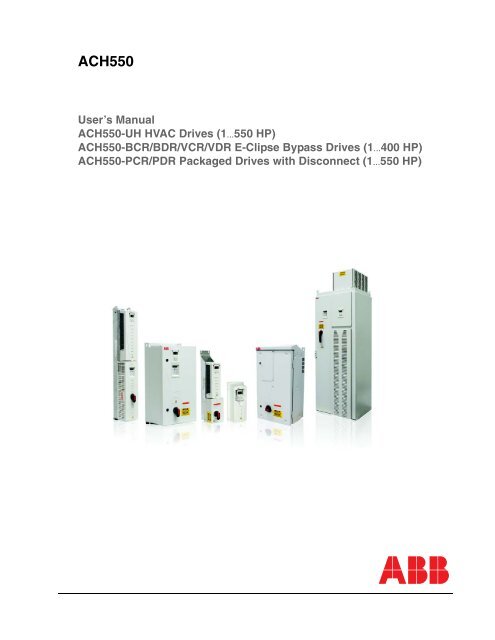
<strong>ACH550</strong><br />
User’s Manual<br />
<strong>ACH550</strong>-UH HVAC Drives (1…550 HP)<br />
<strong>ACH550</strong>-BCR/BDR/VCR/VDR E-Clipse Bypass Drives (1…400 HP)<br />
<strong>ACH550</strong>-PCR/PDR Packaged Drives with Disconnect (1…550 HP)
List of related manuals<br />
GENERAL MANUALS<br />
<strong>ACH550</strong>-UH HVAC Drives User’s Manual (1...550 HP)<br />
Included in this manual<br />
• Safety<br />
• Installation<br />
• Control panel<br />
• Start-up<br />
• Application macros<br />
• Parameters<br />
• Embedded fieldbus<br />
• Fieldbus adapter<br />
• Diagnostics<br />
• Maintenance<br />
• Technical data<br />
<strong>ACH550</strong>-BCR/BDR/VCR/VDR E-Clipse Bypass Drives<br />
User’s Manual (1...400 HP)<br />
Included in this manual<br />
• Safety<br />
• Installation<br />
• Control panel<br />
• Start-up<br />
• Bypass functions overview<br />
• Application macros<br />
• Parameters<br />
• Embedded fieldbus<br />
• Fieldbus adapter<br />
• Diagnostics<br />
• Technical data<br />
<strong>ACH550</strong>-PCR/PDR Packaged Drives with Disconnect<br />
User’s Manual (1...550 HP)<br />
Included in this manual<br />
• Safety<br />
• Installation<br />
• Maintenance<br />
• Technical data<br />
OPTION MANUALS<br />
(delivered with optional equipment)<br />
MFDT-01 FlashDrop User’s Manual<br />
3AFE68591074 (English)<br />
OHDI-01 115/230 V Digital Input Module User’s Manual<br />
3AUA0000003101 (English)<br />
OREL-01 Relay Output Extension Module User’s<br />
Manual<br />
3AUA0000001935 (English)<br />
RCNA-01 ControlNet Adapter User’s Manual<br />
3AFE64506005 (English)<br />
RDNA-01 DeviceNet Adapter User’s Manual<br />
3AFE64504223 (English)<br />
RETA-01 Ethernet Adapter Module User’s Manual<br />
3AFE64539736 (English)<br />
RETA-02 Ethernet Adapter Module User’s Manual<br />
3AFE68895383 (English)<br />
RLON-01 LONWORKS ® Adapter Module User’s<br />
Manual<br />
3AFE64798693 (English)<br />
RPBA-01 PROFIBUS DP Adapter Module User’s<br />
Manual<br />
3AFE64504215 (English)<br />
SREA-01 Ethernet Adapter User’s Manual<br />
3AUA0000042896 (English)<br />
Typical contents<br />
• Safety<br />
• Installation<br />
• Programming/Start-up<br />
• Diagnostics<br />
• Technical data<br />
MAINTENANCE MANUALS<br />
Guide for Capacitor Reforming in ACS50, ACS55,<br />
ACS150, ACS310, ACS320, ACS350, ACS550 and<br />
<strong>ACH550</strong><br />
3AFE68735190 (English)<br />
APOGEE is a registered trademark of Siemens Building<br />
Technologies Inc.<br />
BACnet is a registered trademark of ASHRAE.<br />
ControlNet is a trademark of ODVA.<br />
DeviceNet is a trademark of ODVA.<br />
DRIVECOM is a registered trademark of DRIVECOM User<br />
Group e.V.<br />
EtherNet/IP is a trademark of ODVA.<br />
Interbus is a registered trademark of Interbus Club.<br />
LONWORKS® is a registered trademark of Echelon<br />
Corporation.<br />
Metasys is a registered trademark of Johnson Controls Inc.<br />
Modbus and Modbus/TCP are registered trademarks of<br />
Schneider Automation Inc.<br />
PROFIBUS, PROFIBUS DP and PROFINET IO are<br />
registered trademarks of Profibus International.
iii<br />
Manual contents<br />
List of included manuals<br />
<strong>ACH550</strong>-UH Drives. . . . . . . . . . . . . . . . . . . . . . . . . . . . . . . . . . . . . . . . . . . . . . . . 1-1<br />
<strong>ACH550</strong>-BCR/BDR/VCR/VDR E-Clipse Bypass Drives . . . . . . . . . . . . . . . . . . . 2-1<br />
<strong>ACH550</strong>-PCR/PDR Packaged Drives with Disconnect . . . . . . . . . . . . . . . . . . . 3-1<br />
Manual contents
iv<br />
Manual contents
<strong>ACH550</strong>-UH User’s Manual 1-1<br />
<strong>ACH550</strong>-UH HVAC Drives<br />
1…550 HP<br />
User’s Manual<br />
2010 <strong>ABB</strong>. All Rights Reserved.
<strong>ACH550</strong>-UH User’s Manual 1-3<br />
Safety<br />
Use of warnings and notes<br />
There are two types of safety instructions throughout this manual:<br />
• Notes draw attention to a particular condition or fact, or give information on a<br />
subject.<br />
• Warnings caution you about conditions which can result in serious injury or death<br />
and/or damage to the equipment. They also tell you how to avoid the danger. The<br />
warning symbols are used as follows:<br />
Electricity warning warns of hazards from electricity which can cause physical<br />
injury and/or damage to the equipment.<br />
General warning warns about conditions, other than those caused by electricity,<br />
which can result in physical injury and/or damage to the equipment.<br />
WARNING! The <strong>ACH550</strong> adjustable speed AC drive should ONLY be installed by a<br />
qualified electrician.<br />
WARNING! Even when the motor is stopped, dangerous voltage is present at the<br />
power circuit terminals U1, V1, W1 (L1, L2, L3) and U2, V2, W2 (T1, T2 T3) and,<br />
depending on the frame size, UDC+ and UDC-, or BRK+ and BRK-.<br />
WARNING! Dangerous voltage is present when input power is connected. After<br />
disconnecting the supply, wait at least 5 minutes (to let the intermediate circuit<br />
capacitors discharge) before removing the cover.<br />
WARNING! Even when power is switched off from the input terminals of the<br />
<strong>ACH550</strong>, there may be dangerous voltage (from external sources) on the terminals<br />
of the relay outputs.<br />
WARNING! When the control terminals of two or more drives are connected in<br />
parallel, the auxiliary voltage for these control connections must be taken from a<br />
single source which can either be one of the drives or an external supply.<br />
Safety
1-4 <strong>ACH550</strong>-UH User’s Manual<br />
WARNING! Disconnect the internal EMC filter when installing the drive on an IT<br />
system (an ungrounded power system or a high-resistance-grounded [over 30 ohm]<br />
power system).<br />
WARNING! Do not attempt to install or remove EM1, EM3, F1 or F2 screws while<br />
power is applied to the drive’s input terminals.<br />
WARNING! Do not control the motor with the disconnecting device (disconnecting<br />
means); instead, use the control panel keys or commands via the I/O board of the<br />
drive. The maximum allowed number of charging cycles of the DC capacitors (i.e.<br />
power-ups by applying power) is five in ten minutes.<br />
WARNING! Never attempt to repair a malfunctioning <strong>ACH550</strong>; contact the factory or<br />
your local Authorized Service Center for repair or replacement.<br />
WARNING! The <strong>ACH550</strong> will start up automatically after an input voltage<br />
interruption if the external run command is on.<br />
WARNING! The heat sink may reach a high temperature.<br />
Note: For more technical information, contact the factory or your local <strong>ABB</strong><br />
representative.<br />
Safety
<strong>ACH550</strong>-UH User’s Manual 1-5<br />
Table of contents<br />
Safety<br />
Use of warnings and notes . . . . . . . . . . . . . . . . . . . . . . . . . . . . . . . . . . . . . . . 1-3<br />
Table of contents<br />
Installation<br />
Installation flow chart . . . . . . . . . . . . . . . . . . . . . . . . . . . . . . . . . . . . . . . . . . . 1-9<br />
Preparing for installation . . . . . . . . . . . . . . . . . . . . . . . . . . . . . . . . . . . . . . . . 1-10<br />
Installing the drive . . . . . . . . . . . . . . . . . . . . . . . . . . . . . . . . . . . . . . . . . . . . 1-13<br />
Control panel<br />
HVAC control panel features . . . . . . . . . . . . . . . . . . . . . . . . . . . . . . . . . . . . 1-33<br />
HVAC control panel modes . . . . . . . . . . . . . . . . . . . . . . . . . . . . . . . . . . . . . 1-34<br />
Start-up<br />
Start-up . . . . . . . . . . . . . . . . . . . . . . . . . . . . . . . . . . . . . . . . . . . . . . . . . . . . . 1-47<br />
Application macros<br />
Overview . . . . . . . . . . . . . . . . . . . . . . . . . . . . . . . . . . . . . . . . . . . . . . . . . . . 1-49<br />
HVAC Default macro . . . . . . . . . . . . . . . . . . . . . . . . . . . . . . . . . . . . . . . . . . 1-51<br />
Supply Fan macro . . . . . . . . . . . . . . . . . . . . . . . . . . . . . . . . . . . . . . . . . . . . 1-52<br />
Return Fan macro . . . . . . . . . . . . . . . . . . . . . . . . . . . . . . . . . . . . . . . . . . . . 1-53<br />
Cooling Tower Fan macro . . . . . . . . . . . . . . . . . . . . . . . . . . . . . . . . . . . . . . 1-54<br />
Condenser macro . . . . . . . . . . . . . . . . . . . . . . . . . . . . . . . . . . . . . . . . . . . . . 1-55<br />
Booster Pump macro . . . . . . . . . . . . . . . . . . . . . . . . . . . . . . . . . . . . . . . . . . 1-56<br />
Pump Alternation macro . . . . . . . . . . . . . . . . . . . . . . . . . . . . . . . . . . . . . . . . 1-57<br />
Internal Timer macro . . . . . . . . . . . . . . . . . . . . . . . . . . . . . . . . . . . . . . . . . . 1-58<br />
Internal Timer with Constant Speeds / PRV macro . . . . . . . . . . . . . . . . . . . 1-59<br />
Floating Point macro . . . . . . . . . . . . . . . . . . . . . . . . . . . . . . . . . . . . . . . . . . 1-60<br />
Dual Setpoint with PID macro . . . . . . . . . . . . . . . . . . . . . . . . . . . . . . . . . . . 1-61<br />
Dual Setpoint with PID and Constant Speeds . . . . . . . . . . . . . . . . . . . . . . . 1-62<br />
E-bypass macro . . . . . . . . . . . . . . . . . . . . . . . . . . . . . . . . . . . . . . . . . . . . . . 1-63<br />
Hand Control macro . . . . . . . . . . . . . . . . . . . . . . . . . . . . . . . . . . . . . . . . . . . 1-64<br />
E-Clipse macro . . . . . . . . . . . . . . . . . . . . . . . . . . . . . . . . . . . . . . . . . . . . . . . 1-65<br />
Parameters<br />
Complete parameter list . . . . . . . . . . . . . . . . . . . . . . . . . . . . . . . . . . . . . . . . 1-67<br />
Complete parameter descriptions . . . . . . . . . . . . . . . . . . . . . . . . . . . . . . . . 1-80<br />
Table of contents
1-6 <strong>ACH550</strong>-UH User’s Manual<br />
Embedded fieldbus<br />
Overview . . . . . . . . . . . . . . . . . . . . . . . . . . . . . . . . . . . . . . . . . . . . . . . . . . . 1-187<br />
Mechanical and electrical installation – EFB . . . . . . . . . . . . . . . . . . . . . . . 1-189<br />
Communication setup – EFB . . . . . . . . . . . . . . . . . . . . . . . . . . . . . . . . . . . 1-191<br />
Activate drive control functions – EFB . . . . . . . . . . . . . . . . . . . . . . . . . . . . 1-195<br />
Feedback from the drive – EFB . . . . . . . . . . . . . . . . . . . . . . . . . . . . . . . . . 1-200<br />
Diagnostics – EFB . . . . . . . . . . . . . . . . . . . . . . . . . . . . . . . . . . . . . . . . . . . 1-202<br />
N2 protocol technical data . . . . . . . . . . . . . . . . . . . . . . . . . . . . . . . . . . . . . 1-207<br />
FLN protocol technical data . . . . . . . . . . . . . . . . . . . . . . . . . . . . . . . . . . . . 1-215<br />
BACnet protocol technical data . . . . . . . . . . . . . . . . . . . . . . . . . . . . . . . . . 1-229<br />
Modbus protocol technical data . . . . . . . . . . . . . . . . . . . . . . . . . . . . . . . . . 1-241<br />
<strong>ABB</strong> control profiles technical data . . . . . . . . . . . . . . . . . . . . . . . . . . . . . . . 1-249<br />
Fieldbus adapter<br />
Overview . . . . . . . . . . . . . . . . . . . . . . . . . . . . . . . . . . . . . . . . . . . . . . . . . . . 1-261<br />
Mechanical and electrical installation – FBA . . . . . . . . . . . . . . . . . . . . . . . 1-264<br />
Communication setup – FBA . . . . . . . . . . . . . . . . . . . . . . . . . . . . . . . . . . . 1-265<br />
Activate drive control functions – FBA . . . . . . . . . . . . . . . . . . . . . . . . . . . . 1-265<br />
Feedback from the drive – FBA . . . . . . . . . . . . . . . . . . . . . . . . . . . . . . . . . 1-268<br />
Diagnostics – FBA . . . . . . . . . . . . . . . . . . . . . . . . . . . . . . . . . . . . . . . . . . . 1-269<br />
<strong>ABB</strong> drives profile technical data . . . . . . . . . . . . . . . . . . . . . . . . . . . . . . . . 1-271<br />
Generic profile technical data . . . . . . . . . . . . . . . . . . . . . . . . . . . . . . . . . . . 1-279<br />
Diagnostics<br />
Diagnostic displays . . . . . . . . . . . . . . . . . . . . . . . . . . . . . . . . . . . . . . . . . . . 1-281<br />
Correcting faults . . . . . . . . . . . . . . . . . . . . . . . . . . . . . . . . . . . . . . . . . . . . . 1-282<br />
Correcting alarms . . . . . . . . . . . . . . . . . . . . . . . . . . . . . . . . . . . . . . . . . . . . 1-288<br />
Maintenance<br />
Maintenance intervals . . . . . . . . . . . . . . . . . . . . . . . . . . . . . . . . . . . . . . . . . 1-291<br />
Heatsink . . . . . . . . . . . . . . . . . . . . . . . . . . . . . . . . . . . . . . . . . . . . . . . . . . . 1-291<br />
Drive module fan replacement . . . . . . . . . . . . . . . . . . . . . . . . . . . . . . . . . . 1-292<br />
Enclosure fan replacement – UL Type 12 enclosures . . . . . . . . . . . . . . . . 1-293<br />
Enclosure air filter replacement – UL Type 12 enclosures . . . . . . . . . . . . . 1-295<br />
Capacitors . . . . . . . . . . . . . . . . . . . . . . . . . . . . . . . . . . . . . . . . . . . . . . . . . . 1-298<br />
Control panel . . . . . . . . . . . . . . . . . . . . . . . . . . . . . . . . . . . . . . . . . . . . . . . 1-298<br />
Table of contents
<strong>ACH550</strong>-UH User’s Manual 1-7<br />
Technical data<br />
Ratings . . . . . . . . . . . . . . . . . . . . . . . . . . . . . . . . . . . . . . . . . . . . . . . . . . . . 1-299<br />
Input power connections . . . . . . . . . . . . . . . . . . . . . . . . . . . . . . . . . . . . . . 1-303<br />
Motor connections . . . . . . . . . . . . . . . . . . . . . . . . . . . . . . . . . . . . . . . . . . . 1-311<br />
Control connections . . . . . . . . . . . . . . . . . . . . . . . . . . . . . . . . . . . . . . . . . . 1-317<br />
Efficiency . . . . . . . . . . . . . . . . . . . . . . . . . . . . . . . . . . . . . . . . . . . . . . . . . . 1-320<br />
Cooling . . . . . . . . . . . . . . . . . . . . . . . . . . . . . . . . . . . . . . . . . . . . . . . . . . . . 1-320<br />
Dimensions and weights . . . . . . . . . . . . . . . . . . . . . . . . . . . . . . . . . . . . . . 1-322<br />
Degrees of protection . . . . . . . . . . . . . . . . . . . . . . . . . . . . . . . . . . . . . . . . . 1-327<br />
Ambient conditions . . . . . . . . . . . . . . . . . . . . . . . . . . . . . . . . . . . . . . . . . . . 1-328<br />
Materials . . . . . . . . . . . . . . . . . . . . . . . . . . . . . . . . . . . . . . . . . . . . . . . . . . . 1-329<br />
Applicable standards . . . . . . . . . . . . . . . . . . . . . . . . . . . . . . . . . . . . . . . . . 1-330<br />
Liability limits . . . . . . . . . . . . . . . . . . . . . . . . . . . . . . . . . . . . . . . . . . . . . . . 1-332<br />
Index<br />
Table of contents
1-8 <strong>ACH550</strong>-UH User’s Manual<br />
Table of contents
<strong>ACH550</strong>-UH User’s Manual 1-9<br />
Installation<br />
Study these installation instructions carefully before proceeding. Failure to observe<br />
the warnings and instructions may cause a malfunction or personal hazard.<br />
WARNING! Before you begin read Safety on page 1-3.<br />
Installation flow chart<br />
The installation of the <strong>ACH550</strong> adjustable speed AC drive follows the outline below.<br />
The steps must be carried out in the order shown. At the right of each step are<br />
references to the detailed information needed for the correct installation of the unit.<br />
Task<br />
PREPARE for installation Preparing for installation on page 1-10.<br />
See<br />
PREPARE the mounting location Prepare the mounting location on page 1-14.<br />
REMOVE the front cover Remove front cover on page 1-16.<br />
MOUNT the drive Mount the drive on page 1-17.<br />
INSTALL wiring<br />
Wiring overview on page 1-18 and<br />
Install the wiring on page 1-23.<br />
CHECK installation Check installation on page 1-27.<br />
REINSTALL the cover Re-install cover on page 1-27.<br />
APPLY power Apply power on page 1-29.<br />
START-UP Start-up on page 1-30.<br />
Installation
1-10 <strong>ACH550</strong>-UH User’s Manual<br />
Preparing for installation<br />
Lifting the drive<br />
R1…R6<br />
Lift the drive only by the metal chassis.<br />
R7…R8<br />
IP2040<br />
WARNING! Handle and ship floor mounted enclosures<br />
only in the upright position. These units are not designed<br />
to be laid on their backs.<br />
1. Use a pallet truck to move the transport package/<br />
enclosure to the installation site.<br />
2. Remove the cabinet side panels for access to the<br />
cabinet/pallet mounting bolts. (6 torx screws hold each<br />
cabinet side panel in place. Leave the side panels off<br />
until later.)<br />
3. Remove the 4 bolts that secure the cabinet to the<br />
shipping pallet.<br />
2<br />
PC00005<br />
R70010<br />
WARNING! Use the lifting lugs/bars at the top of the unit<br />
to lift R7/R8 drives.<br />
30 o<br />
4. Use a hoist to lift the drive. (Do not place drive in final<br />
position until mounting site is prepared.)<br />
Unpack the drive<br />
1. Unpack the drive.<br />
2. Check for any damage and notify the shipper<br />
immediately if damaged components are found.<br />
3. Check the contents against the order and the shipping<br />
label to verify that all parts have been received.<br />
PC00003<br />
Installation
<strong>ACH550</strong>-UH User’s Manual 1-11<br />
Drive identification<br />
Drive labels<br />
To determine the type of drive you are installing, refer to either:<br />
• Serial number label attached on upper part of<br />
SW:<br />
V.2.06B<br />
2030700001<br />
the chokeplate between the mounting holes.<br />
• Type code label attached on the heat sink – on<br />
the side of the enclosure.<br />
Input<br />
Voltage (U1)<br />
Current (I1n)<br />
Output<br />
Voltage (U2)<br />
Current (I2n)<br />
3 PH 48…63 Hz<br />
200…240 Vac<br />
59.4 A<br />
3 PH 0…500 Hz<br />
0…U1 Vac<br />
59.4 A<br />
1 PH 4…63 Hz<br />
200…240 Vac<br />
59.4 A<br />
kAIC<br />
3 PH 0…500 Hz<br />
0…U1 Vac<br />
28 A<br />
<strong>ABB</strong> Inc.<br />
Made in USA of foreign parts<br />
Mfg. Date: 01-December-2005<br />
Org. Firmware: V.2.06B<br />
<strong>ACH550</strong>-UH-059A-2<br />
S/N<br />
2030700001<br />
Power (Pn)<br />
20 HP<br />
10 HP<br />
S/N 2030700001<br />
<strong>ACH550</strong>-UH-059A-2<br />
Type code<br />
Use the following chart to interpret the type code found on either label.<br />
<strong>ACH550</strong>-UH-08A8-4+...<br />
AC, HVAC Drive – 550 product series<br />
Construction (region specific)<br />
UH = Setup and parts specific to US installation and NEMA compliance<br />
Output current rating<br />
e.g. 08A8 = 8.8A See section Ratings for details on page 1-299<br />
Voltage rating<br />
2 = 208…240 VAC<br />
4 = 380…480 VAC<br />
6 = 500…600 VAC<br />
Enclosure protection class<br />
No specification = UL type 1 / NEMA 1 / IP 21<br />
+B055 = UL type 12 / NEMA 12 / IP 54<br />
Fieldbus Adapter<br />
+K451 = DeviceNet Adapter +K462 = ControlNet Adapter<br />
+K452 = LonWorks Adapter +K466 = EtherNet Adapter<br />
+K454 = Profibus Adapter<br />
I/O Options<br />
+L511 = Relay Output Extension<br />
+L512 = 115/230 V Digital Input Interface<br />
Ratings and frame size<br />
The chart in section Ratings on page 1-299 lists technical specifications, and<br />
identifies the drive’s frame size. To read the Ratings table, you need the “Output<br />
current rating” entry from the type code (see above). Also, when using the Ratings<br />
tables, note that there are different tables for each drive “Voltage rating”.<br />
Installation
1-12 <strong>ACH550</strong>-UH User’s Manual<br />
Motor compatibility<br />
The motor, drive, and supply power must be compatible:<br />
Motor<br />
Specification<br />
Verify<br />
Motor type 3-phase induction motor –<br />
Nominal current<br />
Motor value is within this<br />
range: 0.15…1.5 * I 2N<br />
(I 2N = normal use current)<br />
Reference<br />
• Type code label on drive, entry for Output I 2N ,<br />
or<br />
• Type code on drive and rating table in<br />
Technical data on page 1-299.<br />
Nominal frequency 10…500 Hz –<br />
Voltage range Motor is compatible with<br />
the <strong>ACH550</strong> voltage range.<br />
208…240 V (for <strong>ACH550</strong>-xx-xxxx-2) or<br />
380…480 V (for <strong>ACH550</strong>-xx-xxxx-4)<br />
500…600 V (for <strong>ACH550</strong>-xx-xxxx-6)<br />
Insulation<br />
500…600 V drives: Either<br />
the motor complies with<br />
NEMA MG1 Part 31, or a<br />
du/dt filter is used between<br />
the motor and drive.<br />
For <strong>ACH550</strong>-xx-xxxx-6<br />
Tools required<br />
To install the <strong>ACH550</strong> you need the following:<br />
• Screwdrivers (as appropriate for the mounting hardware used)<br />
• Wire stripper<br />
• Tape measure<br />
• Drill<br />
• Frame sizes R5…R8 with UL type 12 enclosure: Punch for conduit mounting<br />
holes<br />
• Frame sizes R7/R8: pallet truck and hoist<br />
• For installations involving frame size R6…R8: The appropriate crimping tool for<br />
power cable lugs. See Power terminal considerations – R6 Frame size.<br />
• Mounting hardware: screws or nuts and bolts, four each. The type of hardware<br />
depends on the mounting surface and the frame size:<br />
Frame Size Mounting Hardware Note<br />
R1…R4 M5 #10<br />
R5 M6 1/4 in<br />
R6 M8 5/16 in<br />
R7…R8 M10 7/16 Secures free standing cabinets if required.<br />
• For installations involving frame size R7…R8: Hoist.<br />
Installation
<strong>ACH550</strong>-UH User’s Manual 1-13<br />
Suitable environment and enclosure<br />
Confirm that the site meets the environmental requirements. To prevent damage<br />
prior to installation, store and transport the drive according to the environmental<br />
requirements specified for storage and transportation. See Ambient conditions on<br />
page 1-328.<br />
Confirm that the enclosure is appropriate, based on the site contamination level:<br />
• UL type 1 enclosure. The site must be free of airborne dust, corrosive gases or<br />
liquids, and conductive contaminants such as condensation, carbon dust, and<br />
metallic particles.<br />
• UL type 12 enclosure. This enclosure provides protection from airborne dust and<br />
light sprays or splashing water from all directions.<br />
Suitable mounting location<br />
Installing the drive<br />
Confirm that the mounting location meets the following constraints:<br />
• R1…R6: The drive must be mounted vertically on a smooth, solid surface, and in<br />
a suitable environment as defined above.<br />
• The drive must be located in a suitable environment as defined above.<br />
• The minimum space requirements for the drive are the outside dimensions (see<br />
Outside dimensions – R1…R6 on page 1-325 or Outside dimensions – R7…R8<br />
on page 1-326), plus air flow space around the unit (see Cooling on page 1-320).<br />
• The distance between the motor and the drive is limited by the maximum motor<br />
cable length. See either Motor connection specifications on page 1-311, or<br />
EN 61800-3 compliant motor cables on page 1-314.<br />
• The mounting site must support the drive’s weight. See Weight on page 1-324.<br />
WARNING! Before installing the <strong>ACH550</strong>, ensure the input power supply to the drive<br />
is off.<br />
WARNING! Metal shavings or debris in the enclosure can damage electrical<br />
equipment and create a hazardous condition. Where parts, such as conduit plates<br />
require cutting or drilling, first remove the part. If that is not practical, cover nearby<br />
electrical components to protect them from all shavings or debris.<br />
Installation
1-14 <strong>ACH550</strong>-UH User’s Manual<br />
For flange mounting (mounting the drive in a cooling air duct), see the appropriate<br />
Flange Mounting Instructions:<br />
Frame size<br />
IP21 / UL type 1 IP54 / UL type 12<br />
Kit Code (English) Kit Code (English)<br />
R1 FMK-A-R1 100000982 FMK-B-R1 100000990<br />
R2 FMK-A-R2 100000984 FMK-B-R2 100000992<br />
R3 FMK-A-R3 100000986 FMK-B-R3 100000994<br />
R4 FMK-A-R4 100000988 FMK-B-R4 100000996<br />
R5 AC8-FLNGMT-R5 ACS800-PNTG01U-EN - -<br />
R6 AC8-FLNGMT-R6 - -<br />
Prepare the mounting location<br />
The <strong>ACH550</strong> should only be mounted where all of the<br />
requirements defined in Preparing for installation on<br />
page 1-10 are met.<br />
1. Mark the position of the mounting holes.<br />
1<br />
X0002<br />
Note: Frame sizes R3 and R4 have four holes along the top. Use only two. If<br />
possible, use the two outside holes (to allow room to remove the fan for<br />
maintenance).<br />
Note: ACH400 drives can be replaced using the original mounting holes. For R1 and<br />
R2 frame sizes, the mounting holes are identical. For R3 and R4 frame sizes, the<br />
inside mounting holes on the top of <strong>ACH550</strong> drives match ACH400 mounts.<br />
Installation
<strong>ACH550</strong>-UH User’s Manual 1-15<br />
Note: Frame sizes R7 and R8 have<br />
mounting holes inside the enclosure base.<br />
See Mounting dimensions on page 1-323.<br />
Where it is not possible to use either<br />
mounting hole at the back of the base, use<br />
an L-bracket at the top of the enclosure to<br />
secure the cabinet to a wall or to the back of<br />
another enclosure. Bolt the L-bracket to the<br />
enclosure using the lifting lug bolt hole on<br />
the top of the enclosure.<br />
2. Drill holes of appropriate size in the<br />
mounting location.<br />
PC00023<br />
Fastening points when installed<br />
back against a wall (Top view)<br />
Fastening points when installed<br />
back against back<br />
Fastening the cabinet at the top<br />
using L-brackets (side view)<br />
L-bracket<br />
M12 bolt (1/2 to 9/16 in)<br />
Cabinet top<br />
Installation
1-16 <strong>ACH550</strong>-UH User’s Manual<br />
Remove front cover<br />
R1…R6, UL type 1<br />
1. Remove the control panel, if attached.<br />
2. Loosen the captive screw at the top.<br />
3. Pull near the top to remove the cover.<br />
2<br />
3<br />
1<br />
R1…R6, UL type 12<br />
1. If hood is present: Remove screws (2) holding<br />
the hood in place.<br />
2. If hood is present: Slide hood up and off of the<br />
cover.<br />
3. Loosen the captive screws around the edge of<br />
the cover.<br />
4. Remove the cover.<br />
1<br />
2<br />
IP2000<br />
3<br />
4<br />
FM<br />
R7…R8, Cabinet Door<br />
1. To open the cabinet door, loosen the quarterturn<br />
screws that hold the cabinet door closed.<br />
R7…R8, Side Panels<br />
The side panels were removed to take the<br />
cabinet off the pallet. Installation access is<br />
easier if these panels are kept off throughout<br />
the installation.<br />
1<br />
R70020<br />
Installation
<strong>ACH550</strong>-UH User’s Manual 1-17<br />
Mount the drive<br />
R1…R6, UL type 1<br />
1. Position the <strong>ACH550</strong> onto the mounting screws<br />
or bolts and securely tighten in all four corners.<br />
1<br />
Note: Lift the <strong>ACH550</strong> by its metal chassis.<br />
2. Non-English speaking locations: Add a warning<br />
sticker in the appropriate language over the<br />
existing warning on the top of the module.<br />
R1…R6, UL type 12<br />
For the UL type 12 enclosures, rubber plugs are required in the holes provided for<br />
access to the drive mounting slots.<br />
1. As required for access, remove the rubber plugs.<br />
Push plugs out from the back of the drive.<br />
2. R5 & R6: Align the sheet metal hood (not shown)<br />
in front of the drive’s top mounting holes. (Attach<br />
as part of next step.)<br />
3. Position the <strong>ACH550</strong> onto the mounting screws<br />
or bolts and securely tighten in all four corners.<br />
1, 3<br />
2<br />
2<br />
IP2002<br />
Note: Lift the <strong>ACH550</strong> by its metal chassis<br />
(frame size R6 by the lifting holes on both sides<br />
at the top).<br />
4. Re-install the rubber plugs.<br />
5. Non-English speaking locations: Add a warning sticker in the appropriate language<br />
over the existing warning on the top of the module.<br />
R7…R8<br />
1. Use a hoist to move the cabinet into position.<br />
30 o<br />
Note: If the cabinet location does not provide access to<br />
the cabinet sides, be sure to re-mount side panels before<br />
positioning cabinet.<br />
FM<br />
2. Install and tighten mounting bolts.<br />
PC00003<br />
Installation
1-18 <strong>ACH550</strong>-UH User’s Manual<br />
Wiring overview<br />
Conduit kit<br />
Wiring R1…R6 drives with the UL type 1 Enclosure requires a conduit kit with the<br />
following items:<br />
• conduit box<br />
• screws<br />
• cover<br />
The kit is included with UL type 1 Enclosures.<br />
Wiring requirements<br />
WARNING! Ensure the motor is compatible for use with the <strong>ACH550</strong>. The <strong>ACH550</strong><br />
must be installed by a competent person in accordance with the considerations<br />
defined in Preparing for installation on page 1-10. If in doubt, contact your local <strong>ABB</strong><br />
sales or service office.<br />
As you install the wiring, observe the following:<br />
• There are two sets of wiring instructions – one set for each enclosure type (UL<br />
type 1 and UL type 12). Be sure to select the appropriate procedure.<br />
• For the power connection points on the drive see the Connection diagrams<br />
section below.<br />
• Use separate, metal conduit runs to keep these three classes of wiring apart:<br />
– Input power wiring.<br />
– Motor wiring. (Use a separate, metal conduit run for each drive)<br />
– Control/communications wiring.<br />
• When installing input power and motor wiring, refer to the following, as<br />
appropriate:<br />
Terminal Description Specifications and Notes<br />
U1, V1, W1* 3-phase power supply input Input power connections on page 1-303.<br />
PE Protective Ground Ground connections on page 1-307.<br />
U2, V2, W2 Power output to motor Motor connections on page 1-311.<br />
* The <strong>ACH550</strong> -xx-xxxx-2 (208…240V series) can be used with a single phase supply, if output<br />
current is derated by 50%. For single phase supply voltage connect power at U1 and W1.<br />
• To locate input power and motor connection terminals, see Connection diagrams<br />
starting on page 1-20. For specifications on power terminals, see Drive’s power<br />
connection terminals on page 1-309.<br />
• For corner grounded TN systems, see section Unsymmetrically grounded<br />
networks on page 1-307.<br />
• For IT systems, see section Floating networks on page 1-308.<br />
• For frame size R6, see Power terminal considerations – R6 Frame size on page<br />
1-309 to install the appropriate cable lugs.<br />
Installation
<strong>ACH550</strong>-UH User’s Manual 1-19<br />
• For details on control connections, refer to the following sections:<br />
– Drive’s control connection terminals on page 1-318.<br />
– Control connections on page 1-317.<br />
– Application macros starting on page 1-49.<br />
– Complete parameter descriptions on page 1-80.<br />
– Embedded fieldbus on page 1-187.<br />
– Fieldbus adapter on page 1-261.<br />
• For electro-magnetic compliance (EMC), follow local codes and the requirements<br />
in Motor cable requirements for CE & C-Tick compliance on page 1-313. For<br />
example:<br />
– Properly ground the wire screen cable shields.<br />
– Keep individual un-screened wires between the cable clamps and the screw<br />
terminals as short as possible.<br />
– Route control cables away from power cables.<br />
Installation
1-20 <strong>ACH550</strong>-UH User’s Manual<br />
Connection diagrams<br />
The following diagrams show:<br />
• The terminal layout for frame size R3, which, in general, applies to frame sizes<br />
R1…R6, except for the R5/R6 power and ground terminals.<br />
• The R5/R6 power and ground terminals.<br />
• The terminal layout for R7/R8.<br />
R1…R4 (Diagram shows the R3 frame.)<br />
J1 – DIP Switches for Analog Inputs<br />
The switch is one of two types:<br />
Illustration of available switch<br />
positions; not default settings<br />
AI1: (in Voltage Position)<br />
AI2: (in Current Position)<br />
Original<br />
Alternate<br />
Panel Connector<br />
ON<br />
ON<br />
X1 – Analog Inputs and Outputs<br />
(and 10 V Ref. Voltage Output)<br />
X1 – Digital Inputs<br />
(and 24 V Aux. Voltage Output)<br />
Power LED (Green)<br />
Fault LED (Red)<br />
X1 – Relay Outputs<br />
Illustration of available switch<br />
positions; not default settings<br />
J2 – DIP Switches<br />
for RS485 Termination<br />
J2<br />
J2<br />
Optional Module 1<br />
X1 – Communications<br />
(RS485)<br />
ON<br />
off position<br />
ON<br />
on position<br />
Optional Module 2<br />
Frame Sizes<br />
R5/R6 differ.<br />
See next page.<br />
Power Input<br />
Power Output to Motor<br />
(U1, V1, W1) (U2, V2, W2)<br />
EM3<br />
EM1<br />
GND<br />
PE<br />
X0003<br />
Terminals Not Used<br />
WARNING! To avoid danger, or damage to the drive, on IT systems and corner<br />
grounded TN systems, see section Disconnecting the internal EMC filter on<br />
page 1-22.<br />
Installation
<strong>ACH550</strong>-UH User’s Manual 1-21<br />
The following diagram shows the power and ground terminal layout for frame sizes<br />
R5 and R6.<br />
R5<br />
R6<br />
F2<br />
F1<br />
F2<br />
PE<br />
GND<br />
X0011<br />
GND<br />
Power Input<br />
(U1, V1, W1)<br />
Power Output to Motor<br />
(U2, V2, W2)<br />
F1<br />
Terminals Not Used<br />
Terminals Not Used<br />
Power Input<br />
(U1, V1, W1)<br />
PE<br />
GND<br />
X0013<br />
Power Output to Motor<br />
(U2, V2, W2)<br />
WARNING! To avoid danger, or damage to the drive, on IT systems and corner<br />
grounded TN systems, see section Disconnecting the internal EMC filter on<br />
page 1-22.<br />
Installation
1-22 <strong>ACH550</strong>-UH User’s Manual<br />
The following diagram shows the power and ground terminal layout for frame size<br />
R7 (R8 is similar).<br />
R7<br />
Motor<br />
Terminals<br />
Input Power<br />
Terminals<br />
Ground Lug<br />
Bar<br />
<strong>ACH550</strong><br />
Control Wires<br />
(X1)<br />
Terminal Strip<br />
Only on<br />
<strong>ACH550</strong>-UH<br />
Disconnecting the internal EMC filter<br />
On certain types of systems, you must disconnect the internal EMC filter, otherwise<br />
the system will be connected to ground potential through the EMC filter capacitors,<br />
which might cause danger, or damage the drive.<br />
Note: When the internal EMC filter is disconnected, the drive is not EMC compatible.<br />
The following table shows the installation rules for the EMC filter screws in order to<br />
connect or disconnect the filter, depending on the system type and the frame size.<br />
For more information on the different system types, see Floating networks on page<br />
1-308 and Unsymmetrically grounded networks on page 1-307.<br />
Installation
<strong>ACH550</strong>-UH User’s Manual 1-23<br />
The locations of screws EM1 and EM3 are shown in the diagram on page 1-20. The<br />
locations of screws F1 and F2 are shown in the diagram on page 1-21.<br />
Frame<br />
sizes<br />
Screw<br />
Symmetrically<br />
grounded TN systems<br />
(TN-S systems)<br />
Corner grounded<br />
TN systems<br />
IT systems (ungrounded<br />
or high-resistancegrounded<br />
[> 30 ohm])<br />
EM1 x x<br />
R1…R3<br />
EM3<br />
x<br />
EM1 x x –<br />
R4<br />
EM3 x – –<br />
F1 x x –<br />
R5…R6<br />
F2 x x –<br />
x = Install the screw. (EMC filter will be connected.)<br />
= Replace the screw with the provided polyamide screw. (EMC filter will be disconnected.)<br />
– = Remove the screw. (EMC filter will be disconnected.)<br />
Install the wiring<br />
Checking motor and motor cable insulation<br />
WARNING! Check the motor and motor cable insulation before connecting the drive<br />
to input power. For this test, make sure that motor cables are NOT connected to the<br />
drive.<br />
1. Complete motor cable connections to the motor, but NOT to the drive output<br />
terminals (U2, V2, W2).<br />
2. At the drive end of the motor cable, measure the insulation<br />
resistance between each motor cable phase and Protective<br />
Earth (PE): Apply a voltage of 1 kV DC and verify that ohm<br />
resistance is greater than 1 Mohm.<br />
PE<br />
M<br />
Installation
1-24 <strong>ACH550</strong>-UH User’s Manual<br />
R1…R6, wiring UL type 1 enclosure<br />
1. Open the appropriate knockouts in the<br />
conduit box. (See Conduit kit on page 1-18.)<br />
2. Install thin-wall conduit clamps (not supplied).<br />
3. Install conduit box.<br />
4. Connect conduit runs for input power, motor<br />
and control cables to the box.<br />
2 X0007<br />
3<br />
5. Route input power and motor wiring through<br />
separate conduits.<br />
6. Strip wires.<br />
7. Connect power, motor, and ground wires to<br />
the drive terminals. See Wiring requirements<br />
on page 1-18 and table on the tightening<br />
torques on page 1-309.<br />
7<br />
7<br />
5<br />
4<br />
X0005<br />
IP2004<br />
Note: For R5 frame size, the minimum power cable size is 25 mm 2 (4 AWG). For R6<br />
frame size, refer to Power terminal considerations – R6 Frame size on page 1-309.<br />
8. Route the control cables through the conduit<br />
(not the same conduit as either input power or<br />
motor wiring).<br />
10<br />
9. Use available secure points and tie strap<br />
12<br />
landings to permanently secure control wiring<br />
at a minimum distance of 6 mm (1/4") from<br />
power wiring.<br />
10. Strip the control cable sheathing and twist the<br />
copper screen into a pig-tail.<br />
8<br />
11. Connect the ground screen pig-tail for digital<br />
and analog I/O cables at X1-1. (Ground only<br />
at drive end.)<br />
12. Connect the ground screen pig-tail for RS485<br />
cables at X1-28 or X1-32. (Ground only at<br />
drive end.)<br />
13. Strip and connect the individual control wires to the drive terminals. See Wiring<br />
requirements on page 1-18.<br />
14. Install the conduit box cover (1 screw).<br />
IP2005<br />
Installation
<strong>ACH550</strong>-UH User’s Manual 1-25<br />
R1…R6, wiring UL type 12 enclosure<br />
1. Step depends on Frame Size:<br />
• Frame Sizes R1…R4: Remove and discard the<br />
cable seals where conduit will be installed. (The<br />
cable seals are cone-shaped, rubber seals on<br />
the bottom of the drive.)<br />
R1…R4<br />
1<br />
IP5013<br />
• Frame Sizes R4 and R5: Use punch to create<br />
holes for conduit connections as needed.<br />
R5, R6<br />
1<br />
2. For each conduit run (input power, motor and<br />
control wiring must be separate), install water tight<br />
conduit connectors (not supplied).<br />
2<br />
IP5023<br />
IP5006<br />
3. Route the power wiring through conduit.<br />
4. Route the motor wiring through conduit (not the<br />
same conduit as input power wiring run).<br />
5. Strip the wires.<br />
6. Connect the power, motor, and ground wires to<br />
the drive terminals. See Wiring requirements on<br />
page 1-18, Connection diagrams on page 1-20 and<br />
table for tightening torques on page 1-309.<br />
6<br />
3<br />
4<br />
IP5007<br />
Note: For R5 frame size, the minimum power cable size is 25 mm 2 (4 AWG). For R6<br />
frame size, refer to Power terminal considerations – R6 Frame size on page 1-309.<br />
7. Route the control cables through the conduit (not<br />
the same conduit as either input power or motor<br />
wiring runs).<br />
8. Use available secure points and tie strap landings to<br />
permanently secure control wiring at a minimum<br />
distance of 6 mm (1/4") from power wiring.<br />
9. Strip the control cable sheathing and twist the<br />
copper screen into a pig-tail.<br />
10. Connect the ground screen pig-tail for digital and<br />
analog I/O cables at X1-1. (Ground only at drive<br />
end.)<br />
11. Connect the ground screen pig-tail for RS485 cables<br />
at X1-28 or X1-32. (Ground only at drive end.)<br />
12. Strip and connect the individual control wires to the drive<br />
terminals. See Wiring requirements on page 1-18.<br />
13. Install the conduit box cover (1 screw).<br />
9…11<br />
7<br />
IP5008<br />
Installation
1-26 <strong>ACH550</strong>-UH User’s Manual<br />
R7…R8, wiring (both enclosure types)<br />
The figures show connections in the R7 cabinet, the R8 cabinet is similar.<br />
1. Remove the conduit connection plate from the top of the left bay.<br />
2. Route the input power, motor and control cables to the top of the cabinet. Each cable<br />
type (input power, motor, and control) must be in separate conduit.<br />
3. Use punch to create holes for conduit connections as needed.<br />
4. UL type 12 Enclosure: For each conduit<br />
Gnd<br />
run (input power, motor and control wiring<br />
must be separate), install water tight<br />
Input Power<br />
Cable<br />
conduit connectors (not supplied).<br />
5. Connect input power and motor cables to<br />
the bus terminals. See Wiring requirements<br />
on page 1-18, Connection diagrams on<br />
page 1-20.<br />
Terminal Strip<br />
Only on<br />
<strong>ACH550</strong>-UH<br />
6. Connect grounds to ground bar.<br />
7. Use available secure points and tie strap<br />
landings to permanently secure control<br />
wiring at a minimum distance of 6 mm<br />
(1/4") from power wiring.<br />
8. Strip the control cable sheathing and twist<br />
the copper screen into a pig-tail.<br />
9. Connect the ground screen pig-tail for<br />
digital and analog I/O cables at X1-1.<br />
(Ground only at drive end.)<br />
10. Connect the ground screen pig-tail for<br />
RS485 cables at X1-28 or X1-32. (Ground<br />
only at drive end.)<br />
BP0054<br />
Motor<br />
Cable<br />
BP0054<br />
11. Strip and connect the individual control wires to the drive terminals. See Wiring<br />
requirements on page 1-18.<br />
Gnd<br />
Installation
<strong>ACH550</strong>-UH User’s Manual 1-27<br />
Check installation<br />
Before applying power, perform the following checks.<br />
Check<br />
Installation environment conforms to the drive’s specifications for ambient conditions.<br />
The drive is mounted securely.<br />
Space around the drive meets the drive’s specifications for cooling.<br />
The motor and driven equipment are ready for start.<br />
For floating networks (R1…R6): The internal RFI filter is disconnected (screws EM1 & EM3 or<br />
F1 & F2).<br />
The drive is properly grounded.<br />
The input power voltage matches the drive nominal input voltage range.<br />
The input power connections at U1, V1, and W1 are connected and tightened as specified.<br />
The input power branch circuit protection is installed.<br />
The motor connections at U2, V2, and W2 are connected and tightened as specified.<br />
The input power, motor and control wiring are routed through separate conduit runs.<br />
NO power factor compensation capacitors are in the motor cable.<br />
The control connections are connected and tightened as specified.<br />
NO tools or foreign objects (such as drill shavings) are inside the drive.<br />
NO alternate power source for the motor (such as a bypass connection) is connected – no<br />
voltage is applied to the output of the drive.<br />
Re-install cover<br />
R1…R6, UL type 1<br />
1. Align the cover and slide it on.<br />
2. Tighten the captive screw.<br />
3. Re-install the control panel.<br />
2<br />
1<br />
3<br />
IP2009<br />
Installation
1-28 <strong>ACH550</strong>-UH User’s Manual<br />
R1…R6, UL type 12<br />
1. Align the cover and slide it on.<br />
2. Tighten the captive screws around the edge of<br />
the cover.<br />
3. R1…R4: Slide the hood down over the top of<br />
the cover.<br />
4. R1…R4: Install the two screws that attach the<br />
hood.<br />
5. Re-install the control panel.<br />
Note: The control panel window must be closed<br />
to comply with UL type 12.<br />
4<br />
5<br />
6<br />
3<br />
1<br />
6. Optional: Add a lock (not supplied) to secure<br />
the control panel window.<br />
R7…R8, Covers<br />
1. If side panels were removed and not remounted,<br />
mount them now. Each panel requires 6 torx<br />
screws.<br />
2. Re-mount all high voltage shields.<br />
3. Close all internal swing-out panels and secure in<br />
place with the quarter-turn screws.<br />
4. Close the cabinet door and secure in place with<br />
the quarter-turn screws.<br />
2<br />
1<br />
FM<br />
R70020<br />
Installation
<strong>ACH550</strong>-UH User’s Manual 1-29<br />
Apply power<br />
Always re-install the covers before turning power on.<br />
WARNING! The <strong>ACH550</strong> will start up automatically at power up, if the external run<br />
command is on.<br />
1. Apply input power.<br />
When power is applied to the <strong>ACH550</strong>, the green LED comes on.<br />
Note: Before increasing motor speed, check that the motor is running in the desired<br />
direction. To change rotation direction, switch motor leads as shown below.<br />
Drive<br />
U1 V1 W1 GND U2 V2 W2<br />
L1<br />
Input<br />
L2<br />
Motor<br />
L3<br />
GND<br />
To change rotation direction,<br />
switch motor leads<br />
Drive<br />
U1 V1 W1 GND U2 V2 W2<br />
Input<br />
L1<br />
L2<br />
Motor<br />
L3<br />
GND<br />
FM<br />
Installation
1-30 <strong>ACH550</strong>-UH User’s Manual<br />
Start-up<br />
The <strong>ACH550</strong> has default parameter settings that are sufficient for many situations.<br />
However, review the following situations. Perform the associated procedures as<br />
appropriate.<br />
Spin motor<br />
When first installed and started the control panel displays a welcome screen with the<br />
following options.<br />
• Press Exit to commission the drive as described in section Start-up by changing<br />
the parameters individually on page 1-47.<br />
• Press Enter to move to the following options:<br />
– Select “Commission Drive” to commission the drive as described in section<br />
Start-Up by Start-up by using the Start-Up Assistant on page 1-47.<br />
– Select “Spin Motor” to operate the motor prior to commissioning. This option<br />
operates the motor without any commissioning, except entry of the motor data<br />
as described below. Spin Motor is useful, for example, to operate ventilation<br />
fans prior to commissioning.<br />
Note: When using Spin Motor, the motor speed is limited to the range 1/3…2/3 of<br />
maximum speed. Also, no interlocks are activated. Finally, once the drive is<br />
commissioned, the welcome screen and this option no longer appear.<br />
Motor data<br />
The motor data on the ratings plate may differ from the defaults in the <strong>ACH550</strong>. The<br />
drive provides more precise control and better thermal protection if you enter the<br />
rating plate data.<br />
1. Gather the following from the motor ratings plate:<br />
• Voltage<br />
• Nominal motor current<br />
• Nominal frequency<br />
• Nominal speed<br />
• Nominal power<br />
2. Edit parameters 9905…9909 to the correct values.<br />
• Assistant Control Panel: The Start-Up Assistant walks you through this data entry<br />
(see page 1-37).<br />
• Basic Control Panel: Refer to Parameters Mode on page 1-35, for parameter<br />
editing instructions.<br />
Installation
<strong>ACH550</strong>-UH User’s Manual 1-31<br />
Macros<br />
Note: Selecting the appropriate macro should be part of the original system design,<br />
since the control wiring installed depends on the macro used.<br />
1. Review the macro descriptions in Application macros on page 1-49. Use the macro<br />
that best fits system needs.<br />
2. Edit parameter 9902 to select the appropriate macro. Use either of the following:<br />
• Use the Start-up Assistant, which displays the macro selection immediately after<br />
motor parameter setup.<br />
• Refer to Parameters Mode on page 1-35, for parameter editing instructions.<br />
Tuning – parameters<br />
The system can benefit from one or more of the <strong>ACH550</strong> special features, and/or<br />
fine tuning.<br />
1. Review the parameter descriptions in Complete parameter descriptions starting on<br />
page 1-80. Enable options and fine tune parameter values as appropriate for the<br />
system.<br />
2. Edit parameters as appropriate.<br />
Fault and alarm adjustments<br />
The <strong>ACH550</strong> can detect a wide variety of potential system problems. For example,<br />
initial system operation may generate faults or alarms that indicate set-up problems.<br />
1. Faults and alarms are reported on the control panel with a number. Note the number<br />
reported.<br />
2. Review the description provided for the reported fault/alarm:<br />
• Use the fault and alarm listings on pages 1-282 and 1-288 respectively, or<br />
• Press the help key (Assistant Control Panel only) while fault or alarm is displayed.<br />
3. Adjust the system or parameters as appropriate.<br />
Installation
1-32 <strong>ACH550</strong>-UH User’s Manual<br />
Installation
<strong>ACH550</strong>-UH User’s Manual 1-33<br />
Control panel<br />
HVAC control panel features<br />
The <strong>ACH550</strong> HVAC control panel (ACS-CP-B) features:<br />
Status LED<br />
(Green when normal,<br />
if flashing or red,<br />
see Diagnostics.)<br />
UP<br />
SOFT<br />
KEY 1<br />
SOFT<br />
KEY 2<br />
DOWN<br />
AUTO<br />
HELP (always available)<br />
OFF<br />
HAND<br />
• Language selection for the display<br />
• Drive connection that can be made or detached at any time<br />
• Start-up assistant to facilitate drive commissioning<br />
• Copy function for moving parameters to other <strong>ACH550</strong> drives<br />
• Backup function for saving parameter sets<br />
• Context sensitive help<br />
• Real-time clock<br />
X0201<br />
General display features<br />
Soft key functions<br />
The soft key functions are defined by text displayed just above each key.<br />
Display contrast<br />
To adjust display contrast, simultaneously press and or , as<br />
appropriate.<br />
Control panel
1-34 <strong>ACH550</strong>-UH User’s Manual<br />
HVAC control panel modes<br />
The HVAC control panel has several different modes for configuring, operating and<br />
diagnosing the drive. The modes are:<br />
• Standard Display Mode – Shows drive status information and operates the drive.<br />
• Parameters Mode – Edits parameter values individually.<br />
• Start-up Assistant Mode – Guides the start-up and configuration.<br />
• Changed Parameters Mode – Shows changed parameters.<br />
• Fault Logger Mode – Shows the drive fault history.<br />
• Drive Parameter Backup Mode – Stores or uploads the parameters.<br />
• Clock Set Mode – Sets the time and date for the drive.<br />
• I/O Settings Mode – Checks and edits the I/O settings.<br />
• Alarm Mode – Reporting mode triggered by drive alarms.<br />
Standard Display Mode<br />
Use the Standard Display Mode to read information on the drive’s status and to<br />
operate the drive. To reach the Standard Display Mode, press EXIT until the LCD<br />
display shows status information as described below.<br />
Status information<br />
Top. The top line of the LCD display shows the basic status information of the drive.<br />
• HAND – Indicates that the drive control is local, that is, from the control panel.<br />
• AUTO – Indicates that the drive control is remote, such as the basic I/O (X1) or<br />
fieldbus.<br />
• – Indicates the drive and motor rotation status as follows:<br />
Control panel display<br />
Rotating arrow (clockwise or<br />
counterclockwise)<br />
Rotating dotted arrow blinking<br />
Stationary dotted arrow<br />
Significance<br />
• Drive is running and at setpoint<br />
• Shaft direction is forward or reverse<br />
Drive is running but not at setpoint<br />
Start command is present, but motor is not<br />
running. E.g. start enable is missing.<br />
• Upper right – shows the active reference.<br />
Middle. Using parameter group 34, the middle of the LCD<br />
display can be configured to display:<br />
• One to three parameter values – The default display shows<br />
parameters 0103 (OUTPUT FREQ) in percentages, 0104<br />
(CURRENT) in amperes and 0120 (AI1) in milliamperes.<br />
– Use parameters 3401, 3408, and 3415 to select the parameters (from Group<br />
01) to display. Entering “parameter” 0100 results in no parameter displayed.<br />
For example, if 3401 = 0100 and 3415 = 0100, then only the parameter<br />
specified by 3408 appears in the Control Panel display.<br />
Control panel
<strong>ACH550</strong>-UH User’s Manual 1-35<br />
– You can also scale each parameter in the display, for example, to convert the<br />
motor speed to a display of conveyor speed. Parameters 3402…3405 scale<br />
the parameter specified by 3401, parameters 3409…3412 scale the parameter<br />
specified by 3408, etc.<br />
• A bar meter rather than one of the parameter values.<br />
– Enable bar graph displays using parameters 3404, 3411<br />
and 3418.<br />
Bottom. The bottom of the LCD display shows:<br />
• Lower corners – show the functions currently assigned to the two soft keys.<br />
• Lower middle – displays the current time (if configured to show the time).<br />
Operating the drive<br />
AUTO/HAND – The very first time the drive is powered up, it is in the auto control<br />
(AUTO) mode, and is controlled from the Control terminal block X1.<br />
To switch to hand control (HAND) and control the drive using the control panel, press<br />
and hold the or button.<br />
• Pressing the HAND button switches the drive to hand control while keeping the<br />
drive running.<br />
• Pressing the OFF button switches to hand control and stops the drive.<br />
To switch back to auto control (AUTO), press and hold the<br />
button.<br />
Hand/Auto/Off – To start the drive press the HAND or AUTO buttons, to stop the<br />
drive press the OFF button.<br />
Reference – To modify the reference (only possible if the display in the upper right<br />
corner is in reverse video) press the UP or DOWN buttons (the reference changes<br />
immediately).<br />
The reference can be modified in the local control mode (HAND/OFF), and can be<br />
parameterized (using Group 11 reference select) to also allow modification in the<br />
remote control mode.<br />
Note: The Start/Stop, Shaft direction and Reference functions are only valid in local<br />
control (HAND/OFF) mode.<br />
Parameters Mode<br />
To change the parameters, follow these steps:<br />
Select MENU to enter the main menu.<br />
1<br />
Control panel
1-36 <strong>ACH550</strong>-UH User’s Manual<br />
2<br />
Select the Parameters mode with the UP/<br />
DOWN buttons, and select ENTER to<br />
select the Parameters Mode.<br />
3<br />
Select the appropriate parameter group<br />
with the UP/DOWN buttons and select<br />
SEL.<br />
4<br />
Select the appropriate parameter in a<br />
group with the UP/DOWN buttons. Select<br />
EDIT to change the parameter.<br />
5<br />
Press the UP/DOWN buttons to change<br />
the parameter value.<br />
6<br />
7<br />
Select SAVE to store the modified value<br />
or select CANCEL to leave the set mode.<br />
• Any modifications not saved are<br />
cancelled.<br />
• Each individual parameter setting is<br />
valid immediately after pressing SAVE.<br />
Select EXIT to return to the listing of<br />
parameter groups, and again to return to<br />
the main menu.<br />
For detailed hardware description, see the Appendix.<br />
Note: The current parameter value appears below the highlighted parameter.<br />
Note: To view the default parameter value, press the UP/DOWN buttons<br />
simultaneously.<br />
Note: The most typical and necessary parameters to change are parameter groups<br />
99 Start-up data, 10 Start/Stop/Dir, 11 Reference Select, 20 Limits, 21 Start/Stop, 22<br />
Accel/Decel, 26 Motor Control and 30 Fault Functions.<br />
Note: To restore the default factory settings, select the application macro HVAC<br />
Default.<br />
Control panel
<strong>ACH550</strong>-UH User’s Manual 1-37<br />
Start-Up Assistant Mode<br />
To start the Start-Up Assistant, follow these steps:<br />
Select MENU to enter the main menu<br />
1<br />
2<br />
Select ASSISTANTS with the UP/DOWN<br />
buttons and select ENTER.<br />
3<br />
Scroll to COMMISSION DRIVE with the<br />
UP/DOWN buttons and select SEL.<br />
4<br />
Change the values suggested by the<br />
assistant to your preferences and then<br />
press SAVE after every change.<br />
The Start-Up Assistant will guide you through the start-up.<br />
The Start-Up Assistant guides you through the basic programming of a new drive.<br />
(You should familiarize yourself with basic control panel operation and follow the<br />
steps outlined above.) At the first start, the drive automatically suggests entering the<br />
first task, Language Select.The assistant also checks the values entered to prevent<br />
entries that are out of range.<br />
The Start-Up Assistant is divided into tasks. You may activate the tasks one after the<br />
other, as the Start-Up Assistant suggests, or independently.<br />
Note: If you want to set the parameters independently, use the Parameters Mode.<br />
The order of tasks presented by the Start-up Assistant depends on your entries. The<br />
following task list is typical.<br />
Task name<br />
Description<br />
Spin the motor • Prompts for control panel display language selection.<br />
• Prompts for motor data.<br />
• Guides user through rotation check.<br />
Commission drive Prompts for motor data.<br />
Application<br />
Prompts for application macro selection.<br />
References 1 & 2 • Prompts for the source of speed references 1 and 2.<br />
• Prompts for reference limits.<br />
• Prompts for frequency (or speed) limits.<br />
Control panel
1-38 <strong>ACH550</strong>-UH User’s Manual<br />
Task name<br />
Start/Stop Control • Prompts for the source for start and stop commands.<br />
• Prompts for start and stop mode definition.<br />
• Prompts for acceleration and deceleration times.<br />
Protections • Prompts for current and torque limits.<br />
• Prompts for the use of Run enable and Start enable signals.<br />
• Prompts for the use of emergency stop.<br />
• Prompts for Fault function selection.<br />
• Prompts for Auto reset functions selection.<br />
Constant Speeds • Prompts for the use of constant speeds.<br />
• Prompts for constant speed values.<br />
PID Control • Prompts for PID settings.<br />
• Prompts for the source of process reference.<br />
• Prompts for reference limits.<br />
• Prompts for source, limits and units for the process actual value.<br />
• Defines the use of Sleep function.<br />
Low Noise Setup • Prompts for switching frequency.<br />
• Prompts for definition of Flux optimization.<br />
• Prompts for the use of Critical speeds.<br />
Panel Display Prompts for display variable and unit settings.<br />
Timed Functions Prompts for the use of Timed functions.<br />
Output • Prompts for the signals indicated through the relay outputs.<br />
• Prompts for signals indicated through the analog outputs AO1 and AO2.<br />
Sets the minimum, maximum, scaling and inversion values.<br />
Changed Parameters Mode<br />
To view (and edit) a listing of all parameters that have been changed from macro<br />
default values, follow these steps:<br />
Select MENU to enter the menu.<br />
Description<br />
1<br />
2<br />
Select CHANGED PAR with the UP/<br />
DOWN buttons and select ENTER.<br />
3<br />
A list of changed parameters is displayed.<br />
Select EXIT to exit the Changed<br />
Parameters Mode.<br />
Control panel
<strong>ACH550</strong>-UH User’s Manual 1-39<br />
Fault Logger Mode<br />
Use the Fault Logger Mode to see drive fault history, fault state details and help for<br />
the faults.<br />
1. Select FAULT LOGGER in the Main Menu.<br />
2. Press ENTER to see the latest faults (up to 10 faults, maximum).<br />
3. Press DETAIL to see details for the selected fault.<br />
• Details are available for the three latest faults.<br />
4. Press DIAG to see the help description for the fault. See Diagnostics section.<br />
Note: If a power off occurs, only the three latest faults will remain (with details only in<br />
the first fault).<br />
Drive Parameter Backup Mode<br />
Use the Drive Parameter Backup Mode to export parameters from one drive to<br />
another. The parameters are uploaded from a drive to the control panel and<br />
downloaded from the control panel to another drive. Two options are available:<br />
Par Backup Mode<br />
The Assistant Control Panel can store a full set of drive parameters.<br />
The Par Backup Mode has these functions:<br />
• Upload to Panel – Copies all parameters from the drive to the Control Panel.<br />
This includes user sets of parameters (if defined) and internal parameters such as<br />
those created by the Motor Id Run. The Control Panel memory is non-volatile and<br />
does not depend on the panel’s battery. To upload parameters to control panel,<br />
follow these steps:<br />
1<br />
Select MENU to enter the main<br />
menu.<br />
2<br />
Select PAR BACKUP with the UP/<br />
DOWN buttons and select ENTER.<br />
3<br />
Scroll to Upload to Panel and select<br />
SEL.<br />
Control panel
1-40 <strong>ACH550</strong>-UH User’s Manual<br />
4<br />
The text “Copying parameters” and a<br />
progress diagram is displayed.<br />
Select ABORT if you want to stop<br />
the process.<br />
5<br />
The text “Parameter upload<br />
successful” is displayed and the<br />
control panel returns to the PAR<br />
BACKUP menu. Select EXIT to<br />
return to the main menu. Now you<br />
can disconnect the panel.<br />
• Download <strong>Full</strong> Set – Restores the full parameter set from the Control Panel to<br />
the drive. Use this option to restore a drive, or to configure identical drives. This<br />
download does not include user sets of parameters.<br />
Control<br />
Upload<br />
to panel<br />
Panel<br />
Download<br />
all<br />
IP2100<br />
X0202<br />
IP2100<br />
To download all parameters to drive, follow these steps:<br />
1<br />
Select MENU to enter the menu.<br />
2<br />
Select PAR BACKUP with the UP/<br />
DOWN buttons.<br />
3<br />
Scroll to Download to drive all and<br />
select SEL.<br />
4<br />
The text “Restoring parameters” is<br />
displayed. Select ABORT if you want<br />
to stop the process.<br />
Control panel
<strong>ACH550</strong>-UH User’s Manual 1-41<br />
5<br />
After the download stops, the<br />
message “Parameter download<br />
successful” is displayed and the<br />
control panel goes back to PAR<br />
BACKUP menu. Select EXIT to return<br />
to the main menu.<br />
Note: Download <strong>Full</strong> Set writes all parameters to the drive, including motor<br />
parameters. Only use this function to restore a drive, or to transfer parameters to<br />
systems that are identical to the original system.<br />
• Download Application – Copies a partial parameter set from the Control Panel<br />
to a drive. The partial set does not include internal motor parameters, parameters<br />
9905…9909, 1605, 1607, 5201, nor any Group 51 and 53 parameters. Use this<br />
option to transfer parameters to systems that use similar configurations – the<br />
drive and motor sizes do not need to be the same.<br />
Control<br />
Upload<br />
to panel<br />
Panel<br />
Download<br />
application<br />
X0202<br />
IP2100<br />
IP2101<br />
To download application to drive, follow these steps:<br />
1<br />
Select MENU to enter the menu.<br />
2<br />
Select PAR BACKUP with the UP/<br />
DOWN buttons.<br />
3<br />
Scroll to DOWNLOAD APPLICATION<br />
and select SEL.<br />
4<br />
The text “Downloading parameters<br />
(partial)” is displayed. Select ABORT<br />
if you want to stop the process.<br />
Control panel
1-42 <strong>ACH550</strong>-UH User’s Manual<br />
5<br />
The text “Parameter download<br />
successful” is displayed and the<br />
control panel returns to PAR BACKUP<br />
menu. Select EXIT to return to the<br />
main menu.<br />
• Download User Set 1 - Copies USER S1 parameters (user sets are saved using<br />
parameter 9902 APPLIC MACRO) from the Control Panel to the drive.<br />
• Download User Set 2 - Copies USER S2 parameters from the Control Panel to the<br />
drive.<br />
Handling inexact downloads<br />
In some situations, an exact copy of the download is not appropriate for the target<br />
drive. Some examples:<br />
• A download to an old drive specifies parameters/values that are not available on<br />
the old drive.<br />
• A download (from an old drive) to a new drive does not have definitions for the<br />
new parameters – parameters that did not originally exist.<br />
• A download can include an illegal value for the target drive, e.g. a backup from a<br />
small drive can have a switching frequency of 12 kHz whereas a big drive can<br />
only handle 8k Hz.<br />
As a default, the control panel handles these situations by:<br />
• Discarding parameters/values not available on<br />
the target drive.<br />
• Using parameter default values when the<br />
download provides no values or invalid values.<br />
• Providing a Differences List – A listing of the<br />
type and number of items that the target cannot<br />
accept exactly as specified.<br />
You can either accept the default edits by pressing<br />
READY, or view and edit each item as follows:<br />
LOC DIFFERENCES ----<br />
VALUES UNDER MIN<br />
VALUES OVER MAX<br />
INVALID VALUES<br />
EXTRA PARS<br />
MISSING VALUES<br />
READY<br />
3<br />
2<br />
1<br />
5<br />
7<br />
SEL<br />
1. Highlight an item type in the Differences List (left screen below) and press SEL to<br />
see the details for the selected type (right screen below).<br />
LOC DIFFERENCES ----<br />
VALUES UNDER MIN<br />
VALUES OVER MAX<br />
INVALID VALUES<br />
EXTRA PARS<br />
MISSING VALUES<br />
3<br />
2<br />
1<br />
5<br />
7<br />
LOC INVALID VAL<br />
9902 APLIC MACRO<br />
2606*SWITCHING FREQ<br />
12 kHz<br />
8 kHz<br />
3401*DISP 1 SEL<br />
READY<br />
SEL<br />
EXIT<br />
EDIT<br />
Control panel
<strong>ACH550</strong>-UH User’s Manual 1-43<br />
In the above-right “details” screen:<br />
• The first item that requires editing is automatically highlighted and includes<br />
details: In general, the first item listed in the details is the value defined by the<br />
backup file. The second item listed is the “default edit.”<br />
• For tracking purposes, an asterisk initially appears by each item. As edits are<br />
made, the asterisks disappear.<br />
2. In the illustrated example, the backup specifies a switching frequency of 12 kHz, but<br />
the target drive is limited to 8 kHz.<br />
3. Press EDIT to edit the parameter. The display is the target drive’s standard edit<br />
screen for the selected parameter.<br />
4. Highlight the desired value for the target drive.<br />
5. Press SAVE to save setting.<br />
6. Press EXIT to step back to the differences view and continue for each remaining<br />
exception.<br />
7. When your editing is complete, press READY in the Differences List and then select<br />
“Yes, save parameters.”<br />
Download failures<br />
In some situations, the drive may be unable to accept a download. In those cases,<br />
the control panel display is: “Parameter download failed” plus one of the following<br />
causes:<br />
• Set not found – You are attempting to download a data set that was not defined in<br />
the backup. The remedy is to manually define the set, or upload the set from a<br />
drive that has the desired set definitions.<br />
• Par lock – The remedy is to unlock the parameter set (parameter 1602).<br />
• Incompat drive/model – The remedy is to perform backups only between drives of<br />
the same type (ACS/industrial or ACH/HVAC) and the same model (all <strong>ACH550</strong>).<br />
• Too many differences – The remedy is to manually define a new set, or upload the<br />
set from a drive that more closely resembles the target drive.<br />
Note: If upload or download of parameters is aborted, the partial parameter set is not<br />
implemented.<br />
Clock Set Mode<br />
The Clock Set Mode is used for setting the time and date for the internal clock of the<br />
<strong>ACH550</strong>. In order to use the timer functions of the <strong>ACH550</strong>, the internal clock has to<br />
be set first. Date is used to determine weekdays and is visible in Fault logs.<br />
Control panel
1-44 <strong>ACH550</strong>-UH User’s Manual<br />
To set the clock, follow these steps:<br />
1<br />
Select MENU to enter the main menu.<br />
2<br />
Scroll to Clock Set with the UP/DOWN<br />
buttons and select ENTER to enter the<br />
Clock Set Mode.<br />
3<br />
Scroll to Clock Visibility with the UP/<br />
DOWN buttons and select SEL to change<br />
the visibility of the clock.<br />
4<br />
Scroll to Show Clock with the UP/DOWN<br />
buttons and select SEL to make the clock<br />
visible.<br />
Scroll to Set Time with the UP/DOWN<br />
buttons and select SEL.<br />
5<br />
6<br />
Change the hours and minutes with the<br />
UP/DOWN buttons and select OK to save<br />
the values. The active value is displayed<br />
in inverted color.<br />
7<br />
Scroll to Time Format with the UP/DOWN<br />
buttons and select SEL.<br />
8<br />
The different formats are displayed.<br />
Select a format with the UP/DOWN<br />
buttons and select SEL to confirm the<br />
selection.<br />
Scroll to Set Date with the UP/DOWN<br />
buttons and select SEL.<br />
9<br />
Control panel
<strong>ACH550</strong>-UH User’s Manual 1-45<br />
10<br />
Change the days, months and year with<br />
the UP/DOWN buttons and select OK to<br />
save the values. The active value is<br />
displayed in inverted color.<br />
Scroll to Date Format with the UP/DOWN<br />
buttons and select SEL.<br />
11<br />
12<br />
The Date formats are displayed. Select a<br />
date format with the UP/DOWN buttons<br />
and select OK to confirm the selection.<br />
13<br />
Select EXIT twice to return to the main<br />
menu.<br />
Control panel
1-46 <strong>ACH550</strong>-UH User’s Manual<br />
I/O Settings Mode<br />
To view and edit the I/O settings, follow these steps:<br />
Select MENU to enter the main menu.<br />
1<br />
2<br />
Scroll to I/O Settings with the UP/DOWN<br />
buttons and select ENTER.<br />
3<br />
Scroll to the I/O setting you want to view<br />
with the UP/DOWN buttons and select<br />
SEL.<br />
4<br />
Select the setting you want to view with<br />
the UP/DOWN buttons and select OK.<br />
5<br />
You can change the value with the UP/<br />
DOWN buttons and save it by selecting<br />
SAVE.<br />
If you do not want to change the setting,<br />
select CANCEL.<br />
Select EXIT to return to the main menu.<br />
6<br />
Control panel
<strong>ACH550</strong>-UH User’s Manual 1-47<br />
Start-up<br />
Start-up<br />
Start-up can be performed in two ways:<br />
• Using the Start-Up Assistant.<br />
• Changing the parameters individually.<br />
Start-up by using the Start-Up Assistant<br />
To start the Start-Up Assistant, follow these steps:<br />
Select MENU to enter the main menu.<br />
1<br />
2<br />
Select ASSISTANTS with the Up/Down<br />
buttons and select ENTER.<br />
3<br />
Scroll to COMMISSION DRIVE with the<br />
Up/Down buttons.<br />
4<br />
Change the values suggested by the<br />
assistant to your preferences and then<br />
press SAVE after every change.<br />
The Start-Up Assistant will guide you through the start-up.<br />
Start-up by changing the parameters individually<br />
To change the parameters, follow these steps:<br />
Select MENU to enter the main menu.<br />
1<br />
2<br />
Select the Parameters mode with the UP/<br />
DOWN buttons and select ENTER to<br />
select the Parameters mode.<br />
Start-up
1-48 <strong>ACH550</strong>-UH User’s Manual<br />
3<br />
Select the appropriate parameter group<br />
with the UP/DOWN buttons and select<br />
SEL<br />
4<br />
Select the appropriate parameter in a<br />
group with the UP/DOWN buttons. Select<br />
EDIT to change the parameter value.<br />
5<br />
Press the UP/DOWN buttons to change<br />
the parameter value.<br />
6<br />
Select SAVE to store the modified value or<br />
select CANCEL to leave the set mode.<br />
Any modifications not saved are<br />
cancelled.<br />
7<br />
Select EXIT to return to the listing of<br />
parameter groups, and again to return to<br />
the main menu.<br />
To complete the control connections by manually entering the parameters, see<br />
Parameters Mode on page 1-35.<br />
For detailed hardware description, see the Technical data section on page 1-299.<br />
Note: The current parameter value appears below the highlighted parameter.<br />
Note: To view the default parameter value, press the UP/DOWN buttons<br />
simultaneously.<br />
Note: The most typical and necessary parameters to change are parameter groups<br />
99 Start-up data, 10 Start/Stop/Dir, 11 Reference Select, 20 Limits, 21 Start/Stop, 22<br />
Accel/Decel, 26 Motor Control and 30 Fault Functions.<br />
Note: To restore the default factory settings, select the application macro HVAC<br />
Default.<br />
Start-up
<strong>ACH550</strong>-UH User’s Manual 1-49<br />
Application macros<br />
Overview<br />
Macros change a group of parameters to new, predefined values designed for<br />
specific applications. Use macros to minimize the need for manual editing of<br />
parameters. Selecting a macro sets all other parameters to their default values,<br />
except:<br />
• Group 99: Start-up Data parameters (except parameter 9904)<br />
• The PARAMETER LOCK 1602<br />
• The PARAM SAVE 1607<br />
• The COMM FAULT FUNC 3018 and COMM FAULT TIME 3019<br />
• The COMM PROT SEL 9802<br />
• Groups 51…53 serial communication parameters<br />
• Group 29: Maintenance triggers<br />
After selecting a macro, additional parameter changes can be made manually using<br />
the control panel.<br />
Application macros are enabled by setting the value for parameter 9902 APPLIC<br />
MACRO. By default, HVAC Default (value 1) is the enabled macro.<br />
General considerations<br />
The following considerations apply for all macros:<br />
• When using a direct speed reference in AUTO mode, connect the speed<br />
reference to analog input 1 (AI1), and provide the START command using digital<br />
input 1 (DI1). In HAND/OFF mode, the control panel provides the speed<br />
reference and START command.<br />
• When using process PID, connect the feedback signal to analog input 2 (AI2). As<br />
a default, the control panel sets the Setpoint, but analog input 1 can be used as<br />
an alternate source. You can set up process PID using parameters (Group 40) or<br />
using the PID control assistant (recommended).<br />
Application macros
1-50 <strong>ACH550</strong>-UH User’s Manual<br />
Application / macro listing<br />
This section describes the following macros:<br />
9902<br />
Value<br />
Macro<br />
9902<br />
Value<br />
Macro<br />
1 HVAC Default 9 Internal Timer with Constant Speeds<br />
2 Supply Fan 10 Floating Point<br />
3 Return Fan 11 Dual Setpoint PID<br />
4 Cooling Tower Fan 12 Dual Setpoint PID with Constant Speeds<br />
5 Condenser 13 E-bypass<br />
6 Booster Pump 14 Hand Control<br />
7 Pump Alternation 15 E-Clipse<br />
8 Internal Timer<br />
Selecting an application macro<br />
To select a macro, follow these steps:<br />
Select MENU to enter the main menu.<br />
1<br />
2<br />
Select ASSISTANTS with the UP/DOWN<br />
buttons and select ENTER.<br />
3<br />
Scroll to APPLICATION and select<br />
ENTER.<br />
4<br />
Select a macro with the UP/DOWN buttons<br />
and select SAVE.<br />
Restoring defaults<br />
To restore the factory default settings, select the application macro HVAC Default.<br />
Control wiring<br />
Each macro has specific requirements for control wiring. For general details<br />
about the <strong>ACH550</strong> control wiring terminals, see Control terminal descriptions on<br />
page 1-318. Specific wiring requirements are included with each macro description.<br />
Application macros
<strong>ACH550</strong>-UH User’s Manual 1-51<br />
HVAC Default macro<br />
This macro provides the factory default parameter settings for the <strong>ACH550</strong>-UH.<br />
Factory defaults can be restored at any time by setting parameter 9902 to 1. The<br />
diagram below shows typical wiring using this macro. When using direct speed<br />
reference in AUTO mode or process PID, see General considerations on page 1-49.<br />
+<br />
+<br />
mA<br />
mA<br />
X1<br />
1 SCR<br />
2 AI1<br />
3 AGND<br />
4 10V<br />
5 AI2<br />
6 AGND<br />
7 AO1<br />
8 AO2<br />
9 AGND<br />
10 24V<br />
11 GND<br />
12 DCOM<br />
13 DI1<br />
14 DI2<br />
15 DI3<br />
16 DI4<br />
17 DI5<br />
18 DI6<br />
19 RO1C<br />
20 RO1A<br />
21 RO1B<br />
22 RO2C<br />
23 RO2A<br />
24 RO2B<br />
25 RO3C<br />
26 RO3A<br />
27 RO3B<br />
Signal cable shield (screen)<br />
External reference 0(2)…10 V or 0(4)…20 mA<br />
Analog input circuit common<br />
Reference voltage 10 VDC<br />
PID feedback: 0(2)…10 V or 0(4)…20 mA<br />
Analog input circuit common<br />
J1 Jumper Settings<br />
Output frequency: 0(4)…20 mA<br />
ON<br />
AI1: 0(4)…20 mA<br />
Output current: 0(4)…20 mA<br />
AI2: 0(4)…20 mA<br />
Analog output circuit common<br />
Auxiliary voltage output +24 VDC<br />
Auxiliary voltage output common<br />
Digital input common for all<br />
Start/Stop: Activate to start drive<br />
Not configured<br />
Constant (Preset) speed 1 (P 1202)<br />
Safety interlock: Deactivate to stop drive (P 1608)<br />
Not configured<br />
Not configured<br />
Relay output 1 (P 1401)<br />
Default operation: Ready =>19 connected to 21<br />
Relay output 2 (P 1402)<br />
Default operation: Running =>22 connected to 24<br />
Relay output 3 (P 1403)<br />
Default operation: Fault (-1) =>25 connected to 27<br />
(Fault => 25 connected to 26)<br />
ON ON<br />
1 2<br />
Parameters Changed Relative to HVAC Default<br />
Parameter Value Parameter Value<br />
None (Default macro)<br />
Application macros
1-52 <strong>ACH550</strong>-UH User’s Manual<br />
Supply Fan macro<br />
This macro configures for supply fan applications where the supply fan brings fresh<br />
air in according to signals received from a transducer. When using direct speed<br />
reference in AUTO mode or process PID, see General considerations on page 1-49.<br />
+<br />
+<br />
mA<br />
mA<br />
X1<br />
1 SCR<br />
2 AI1<br />
3 AGND<br />
4 10V<br />
5 AI2<br />
6 AGND<br />
7 AO1<br />
8 AO2<br />
9 AGND<br />
10 24V<br />
11 GND<br />
12 DCOM<br />
13 DI1<br />
14 DI2<br />
15 DI3<br />
16 DI4<br />
17 DI5<br />
18 DI6<br />
19 RO1C<br />
20 RO1A<br />
21 RO1B<br />
22 RO2C<br />
23 RO2A<br />
24 RO2B<br />
25 RO3C<br />
26 RO3A<br />
27 RO3B<br />
Signal cable shield (screen)<br />
External reference 0(2)…10 V or 0(4)…20 mA<br />
Analog input circuit common<br />
Reference voltage 10 VDC<br />
PID feedback: 0(2)…10 V or 0(4)…20 mA<br />
Analog input circuit common<br />
J1 Jumper Settings<br />
Output frequency: 0(4)…20 mA<br />
ON<br />
AI1: 0(4)…20 mA<br />
Output current: 0(4)…20 mA<br />
Analog output circuit common<br />
AI2: 0(4)…20 mA<br />
Auxiliary voltage output +24 VDC<br />
Auxiliary voltage output common<br />
Digital input common for all<br />
Start/Stop: Activate to start drive<br />
Run permissive: Deactivate to stop drive (P 1601)<br />
Constant (Preset) speed 1 (P 1202 1 )<br />
Safety interlock 1: Deactivate to stop drive (P 1608)<br />
Safety interlock 2: Deactivate to stop drive (P 1609)<br />
Not configured<br />
Relay output 1 (P 1401)<br />
Default operation: Started =>19 connected to 21<br />
Relay output 2 (P 1402)<br />
Default operation: Running =>22 connected to 24<br />
Relay output 3 (P 1403)<br />
Default operation: Fault (-1) =>25 connected to 27<br />
(Fault => 25 connected to 26)<br />
ON ON<br />
1 2<br />
Parameters Changed Relative to HVAC Default<br />
Parameter Value Parameter Value<br />
9902 APPLIC MACRO 2 (SUPPLY FAN) 1601 RUN ENABLE 2 (DI2)<br />
1401 RELAY OUTPUT 1 7 (STARTED) 1609 START ENABLE 2 5 (DI5)<br />
Application macros
<strong>ACH550</strong>-UH User’s Manual 1-53<br />
Return Fan macro<br />
This macro configures for return fan applications where the return fan removes air<br />
according to signals received from a transducer. When using direct speed reference<br />
in AUTO mode or process PID, see General considerations on page 1-49.<br />
+<br />
mA<br />
+<br />
mA<br />
X1<br />
1 SCR<br />
2 AI1<br />
3 AGND<br />
4 10V<br />
5 AI2<br />
6 AGND<br />
7 AO1<br />
8 AO2<br />
9 AGND<br />
10 24V<br />
11 GND<br />
12 DCOM<br />
13 DI1<br />
14 DI2<br />
15 DI3<br />
16 DI4<br />
17 DI5<br />
18 DI6<br />
Signal cable shield (screen)<br />
External reference 0(2)…10 V or 0(4)…20 mA<br />
Analog input circuit common<br />
Reference voltage 10 VDC<br />
PID feedback: 0(2)…10 V or 0(4)…20 mA<br />
Analog input circuit common<br />
J1 Jumper Settings<br />
Output frequency: 0(4)…20 mA<br />
ON<br />
AI1: 0(4)…20 mA<br />
Output current: 0(4)…20 mA<br />
Analog output circuit common<br />
AI2: 0(4)…20 mA<br />
Auxiliary voltage output +24 VDC<br />
Auxiliary voltage output common<br />
Digital input common for all<br />
Start/Stop: Activate to start drive<br />
Run permissive: Deactivate to stop drive (P 1601)<br />
Constant (Preset) speed 1 (P 1202 1 )<br />
Safety interlock 1: Deactivate to stop drive (P 1608)<br />
Safety interlock 2: Deactivate to stop drive (P 1609)<br />
Not configured<br />
ON ON<br />
1 2<br />
19 RO1C<br />
20 RO1A<br />
21 RO1B<br />
22 RO2C<br />
23 RO2A<br />
24 RO2B<br />
25 RO3C<br />
26 RO3A<br />
27 RO3B<br />
Relay output 1 (P 1401)<br />
Default operation: Started =>19 connected to 21<br />
Relay output 2 (P 1402)<br />
Default operation: Running =>22 connected to 24<br />
Relay output 3 (P 1403)<br />
Default operation: Fault (-1) =>25 connected to 27<br />
(Fault => 25 connected to 26)<br />
Parameters Changed Relative to HVAC Default<br />
Parameter Value Parameter Value<br />
9902 APPLIC MACRO 3 (RETURN FAN) 1609 START ENABLE 2 5 (DI5)<br />
1401 RELAY OUTPUT 1 7 (STARTED)<br />
Application macros
1-54 <strong>ACH550</strong>-UH User’s Manual<br />
Cooling Tower Fan macro<br />
This macro configures for cooling tower fan applications where the fan speed is<br />
controlled according to the signals received from a transducer. When using direct<br />
speed reference in AUTO mode or process PID, see General considerations on<br />
page 1-49.<br />
+<br />
mA<br />
+<br />
mA<br />
X1<br />
1 SCR<br />
2 AI1<br />
3 AGND<br />
4 10V<br />
5 AI2<br />
6 AGND<br />
7 AO1<br />
8 AO2<br />
9 AGND<br />
10 24V<br />
11 GND<br />
12 DCOM<br />
13 DI1<br />
14 DI2<br />
15 DI3<br />
16 DI4<br />
17 DI5<br />
18 DI6<br />
Signal cable shield (screen)<br />
External reference 0(2)…10 V or 0(4)…20 mA<br />
Analog input circuit common<br />
Reference voltage 10 VDC<br />
PID feedback: 0(2)…10 V or 0(4)…20 mA<br />
Analog input circuit common<br />
J1 Jumper Settings<br />
Output frequency: 0(4)…20 mA<br />
ON<br />
AI1: 0(4)…20 mA<br />
Output current: 0(4)…20 mA<br />
Analog output circuit common<br />
AI2: 0(4)…20 mA<br />
Auxiliary voltage output +24 VDC<br />
Auxiliary voltage output common<br />
Digital input common for all<br />
Start/Stop: Activate to start drive<br />
Run permissive: Deactivate to stop drive (P 1601)<br />
Constant (Preset) speed 1 (P 1202 1 )<br />
Safety interlock 1: Deactivate to stop drive (P 1608)<br />
Safety interlock 2: Deactivate to stop drive (P 1609)<br />
Not configured<br />
ON ON<br />
1 2<br />
19 RO1C<br />
20 RO1A<br />
21 RO1B<br />
22 RO2C<br />
23 RO2A<br />
24 RO2B<br />
25 RO3C<br />
26 RO3A<br />
27 RO3B<br />
Relay output 1 (P 1401)<br />
Default operation: Started =>19 connected to 21<br />
Relay output 2 (P 1402)<br />
Default operation: Running =>22 connected to 24<br />
Relay output 3 (P 1403)<br />
Default operation: Fault (-1) =>25 connected to 27<br />
(Fault => 25 connected to 26)<br />
Parameters Changed Relative to HVAC Default<br />
Parameter Value Parameter Value<br />
9902 APPLIC MACRO 4 (CLNG TWR FAN) 4005 ERROR VALUE INV 1 (YES)<br />
2007 MINIMUM FREQ 20.0 Hz<br />
Application macros
<strong>ACH550</strong>-UH User’s Manual 1-55<br />
Condenser macro<br />
This macro configures for condenser and liquid cooler applications where fan speed<br />
is controlled according to signals received from a transducer. When using direct<br />
speed reference in AUTO mode or process PID, see General considerations on<br />
page 1-49.<br />
+<br />
mA<br />
+<br />
mA<br />
X1<br />
1 SCR<br />
2 AI1<br />
3 AGND<br />
4 10V<br />
5 AI2<br />
6 AGND<br />
7 AO1<br />
8 AO2<br />
9 AGND<br />
10 24V<br />
11 GND<br />
12 DCOM<br />
13 DI1<br />
14 DI2<br />
15 DI3<br />
16 DI4<br />
17 DI5<br />
18 DI6<br />
Signal cable shield (screen)<br />
External reference 0(2)…10 V or 0(4)…20 mA<br />
Analog input circuit common<br />
Reference voltage 10 VDC<br />
PID feedback: 0(2)…10 V or 0(4)…20 mA<br />
Analog input circuit common<br />
J1 Jumper Settings<br />
Output frequency: 0(4)…20 mA<br />
ON<br />
AI1: 0(4)…20 mA<br />
Output current: 0(4)…20 mA<br />
Analog output circuit common<br />
AI2: 0(4)…20 mA<br />
Auxiliary voltage output +24 VDC<br />
Auxiliary voltage output common<br />
Digital input common for all<br />
Start/Stop: Activate to start drive<br />
Run permissive: Deactivate to stop drive (P 1601)<br />
Constant (Preset) speed 1 (P 1202 1 )<br />
Safety interlock 1: Deactivate to stop drive (P 1608)<br />
Safety interlock 2: Deactivate to stop drive (P 1609)<br />
Not configured<br />
ON ON<br />
1 2<br />
19 RO1C<br />
20 RO1A<br />
21 RO1B<br />
22 RO2C<br />
23 RO2A<br />
24 RO2B<br />
25 RO3C<br />
26 RO3A<br />
27 RO3B<br />
Relay output 1 (P 1401)<br />
Default operation: Started =>19 connected to 21<br />
Relay output 2 (P 1402)<br />
Default operation: Running =>22 connected to 24<br />
Relay output 3 (P 1403)<br />
Default operation: Fault (-1) =>25 connected to 27<br />
(Fault => 25 connected to 26)<br />
Parameters Changed Relative to HVAC Default<br />
Parameter Value Parameter Value<br />
9902 APPLIC MACRO 5 (CONDENSER) 4005 ERROR VALUE INV 1 (YES)<br />
Application macros
1-56 <strong>ACH550</strong>-UH User’s Manual<br />
Booster Pump macro<br />
This macro configures for booster pump applications where the pump speed is<br />
controlled according to a signal received from a transducer. When using direct speed<br />
reference in AUTO mode or process PID, see General considerations on page 1-49.<br />
+<br />
mA<br />
+<br />
mA<br />
X1<br />
1 SCR<br />
2 AI1<br />
3 AGND<br />
4 10V<br />
5 AI2<br />
6 AGND<br />
7 AO1<br />
8 AO2<br />
9 AGND<br />
10 24V<br />
11 GND<br />
12 DCOM<br />
13 DI1<br />
14 DI2<br />
15 DI3<br />
16 DI4<br />
17 DI5<br />
18 DI6<br />
Signal cable shield (screen)<br />
External reference 0(2)…10 V or 0(4)…20 mA<br />
Analog input circuit common<br />
Reference voltage 10 VDC<br />
PID feedback: 0(2)…10 V or 0(4)…20 mA<br />
Analog input circuit common<br />
J1 Jumper Settings<br />
Output frequency: 0(4)…20 mA<br />
ON<br />
AI1: 0(4)…20 mA<br />
Output current: 0(4)…20 mA<br />
Analog output circuit common<br />
AI2: 0(4)…20 mA<br />
Auxiliary voltage output +24 VDC<br />
Auxiliary voltage output common<br />
Digital input common for all<br />
Start/Stop: Activate to start drive<br />
Run permissive: Deactivate to stop drive (P 1601)<br />
Constant (Preset) speed 1 (P 1202 1 )<br />
Safety interlock 1: Deactivate to stop drive (P 1608)<br />
Safety interlock 2: Deactivate to stop drive (P 1609)<br />
Not configured<br />
ON ON<br />
1 2<br />
19 RO1C<br />
20 RO1A<br />
21 RO1B<br />
22 RO2C<br />
23 RO2A<br />
24 RO2B<br />
25 RO3C<br />
26 RO3A<br />
27 RO3B<br />
Relay output 1 (P 1401)<br />
Default operation: Started =>19 connected to 21<br />
Relay output 2 (P 1402)<br />
Default operation: Running =>22 connected to 24<br />
Relay output 3 (P 1403)<br />
Default operation: Fault (-1) =>25 connected to 27<br />
(Fault => 25 connected to 26)<br />
Parameters Changed Relative to HVAC Default<br />
Parameter Value Parameter Value<br />
9902 APPLIC MACRO 6 (BOOSTER PUMP) 2202 ACCELER TIME 1 10.0 s<br />
2101 START FUNCTION 8 (RAMP) 2203 DECELER TIME 1 10.0 s<br />
Application macros
<strong>ACH550</strong>-UH User’s Manual 1-57<br />
Pump Alternation macro<br />
This macro configures for pump alternation applications, usually used in booster<br />
stations. To adjust/maintain pressure in the network, the speed of the one pump<br />
changes according to a signal received from a pressure transducer. When the<br />
variable speed pump reaches a maximum speed limit, auxiliary pumps start as<br />
needed. When using process PID, see General considerations on page 1-49. To use<br />
more than one (the default) Auxiliary pump, see parameter group 81.<br />
+<br />
mA<br />
+<br />
mA<br />
X1<br />
1 SCR<br />
2 AI1<br />
3 AGND<br />
4 10V<br />
5 AI2<br />
6 AGND<br />
7 AO1<br />
8 AO2<br />
9 AGND<br />
10 24V<br />
11 GND<br />
12 DCOM<br />
13 DI1<br />
14 DI2<br />
15 DI3<br />
16 DI4<br />
17 DI5<br />
18 DI6<br />
Signal cable shield (screen)<br />
External reference 0(2)…10 V or 0(4)…20 mA<br />
Analog input circuit common<br />
Reference voltage 10 VDC<br />
PID feedback: 0(2)…10 V or 0(4)…20 mA<br />
Analog input circuit common<br />
J1 Jumper Settings<br />
Output frequency: 0(4)…20 mA<br />
ON<br />
AI1: 0(4)…20 mA<br />
Output current: 0(4)…20 mA<br />
Analog output circuit common<br />
AI2: 0(4)…20 mA<br />
Auxiliary voltage output +24 VDC<br />
Auxiliary voltage output common<br />
Digital input common for all<br />
Start/Stop: Activate to start drive<br />
Run permissive: Deactivate to stop drive (P 1601)<br />
Not configured<br />
PFA interlock 1: Deactivate to stop drive (P 1608)<br />
PFA interlock 2: Deactivate to stop drive (P 1609)<br />
Not configured<br />
ON ON<br />
1 2<br />
19 RO1C<br />
20 RO1A<br />
21 RO1B<br />
22 RO2C<br />
23 RO2A<br />
24 RO2B<br />
25 RO3C<br />
26 RO3A<br />
27 RO3B<br />
Relay output 1 (P 1401)<br />
Default operation: PFA (starts lag pump)<br />
Relay output 2 (P 1402)<br />
Default operation: Running =>22 connected to 24<br />
Relay output 3 (P 1403)<br />
Default operation: Fault (-1) =>25 connected to 27<br />
(Fault => 25 connected to 26)<br />
Parameters Changed Relative to HVAC Default<br />
Parameter Value Parameter Value<br />
9902 APPLIC MACRO 7 (PUMP ALTERNA) 2203 DECELER TIME 1 10.0 s<br />
1201 CONST SPEED SEL 0 (NOT SEL) 8109 START FREQ 1 58.0 HZ<br />
1401 RELAY OUTPUT 1 31 (PFA) 8110 START FREQ 2 58.0 HZ<br />
1608 START ENABLE 1 0 (NOT SEL) 8111 START FREQ 3 58.0 HZ<br />
2101 START FUNCTION 8 (RAMP) 8123 PFA ENABLE 1 (ACTIVE)<br />
2202 ACCELER TIME 1 10.0 s<br />
Application macros
1-58 <strong>ACH550</strong>-UH User’s Manual<br />
Internal Timer macro<br />
This macro configures for applications where a built-in timer starts and stops the<br />
motor. When the variable speed pump reaches a maximum speed limit, auxiliary<br />
pumps start as needed. When using direct speed reference in AUTO mode or<br />
process PID, see General considerations on page 1-49.<br />
Momentarily activating digital input 3 (DI3) provides a boost function which operates<br />
the motor. See group 36, Timer Functions, for more information on setting up timers.<br />
+<br />
+<br />
mA<br />
mA<br />
X1<br />
1 SCR<br />
2 AI1<br />
3 AGND<br />
4 10V<br />
5 AI2<br />
6 AGND<br />
7 AO1<br />
8 AO2<br />
9 AGND<br />
10 24V<br />
11 GND<br />
12 DCOM<br />
13 DI1<br />
14 DI2<br />
15 DI3<br />
16 DI4<br />
17 DI5<br />
18 DI6<br />
Signal cable shield (screen)<br />
External reference 0(2)…10 V or 0(4)…20 mA<br />
Analog input circuit common<br />
Reference voltage 10 VDC<br />
PID feedback: 0(2)…10 V or 0(4)…20 mA<br />
Analog input circuit common<br />
J1 Jumper Settings<br />
Output frequency: 0(4)…20 mA<br />
ON<br />
AI1: 0(4)…20 mA<br />
Output current: 0(4)…20 mA<br />
AI2: 0(4)…20 mA<br />
Analog output circuit common<br />
Auxiliary voltage output +24 VDC<br />
Auxiliary voltage output common<br />
Digital input common for all<br />
Timer enable: Activate to start/stop drive from timer<br />
Run permissive: Deactivate to stop drive (P 1601)<br />
Timer override: Activate to start drive<br />
Safety interlock 1: Deactivate to stop drive (P 1608)<br />
Safety interlock 2: Deactivate to stop drive (P 1609)<br />
Not configured<br />
ON ON<br />
1 2<br />
19 RO1C<br />
20 RO1A<br />
21 RO1B<br />
22 RO2C<br />
23 RO2A<br />
24 RO2B<br />
25 RO3C<br />
26 RO3A<br />
27 RO3B<br />
Relay output 1 (P 1401)<br />
Default operation: Started =>19 connected to 21<br />
Relay output 2 (P 1402)<br />
Default operation: Running =>22 connected to 24<br />
Relay output 3 (P 1403)<br />
Default operation: Fault (-1) =>25 connected to 27<br />
(Fault => 25 connected to 26)<br />
Parameters Changed Relative to HVAC Default<br />
Parameter Value Parameter Value<br />
9902 APPLIC MACRO 8 (INT TIMER) 1601 RUN ENABLE 2 (DI2)<br />
1001 EXT1 COMMANDS 11 (TIMER 1) 1609 START ENABLE 2 5 (DI5)<br />
1002 EXT2 COMMANDS 11 (TIMER 1) 3601 TIMERS ENABLE 1 (DI1)<br />
1201 CONST SPEED SEL 0 (NOT SEL) 3622 BOOST SEL 3 (DI3)<br />
1401 RELAY OUTPUT 1 7 (STARTED) 3626 TIMER 1 SRC 31 (P1+2+3+4+B)<br />
Application macros
<strong>ACH550</strong>-UH User’s Manual 1-59<br />
Internal Timer with Constant Speeds / PRV macro<br />
This macro configures for applications such as a timed powered roof ventilator<br />
(PRV) which alternates between two constant speeds (constant speed 1 and 2)<br />
based on a built-in timer.<br />
Momentarily activating digital input 3 (DI3) provides a boost function which operates<br />
the motor. See group 36, Timer Functions, for more information on setting up timers.<br />
+<br />
mA<br />
mA<br />
X1<br />
1 SCR<br />
2 AI1<br />
3 AGND<br />
4 10V<br />
5 AI2<br />
6 AGND<br />
7 AO1<br />
8 AO2<br />
9 AGND<br />
10 24V<br />
11 GND<br />
12 DCOM<br />
13 DI1<br />
14 DI2<br />
15 DI3<br />
16 DI4<br />
17 DI5<br />
18 DI6<br />
Signal cable shield (screen)<br />
External reference 0(2)…10 V or 0(4)…20 mA<br />
Analog input circuit common<br />
Reference voltage 10 VDC<br />
Not configured<br />
Analog input circuit common<br />
J1<br />
Output frequency: 0(4)…20 mA<br />
Jumper Settings<br />
ON<br />
Output current: 0(4)…20 mA<br />
AI1: 0(4)…20 mA<br />
Analog output circuit common<br />
AI2: 0(4)…20 mA<br />
Auxiliary voltage output +24 VDC<br />
Auxiliary voltage output common<br />
Digital input common for all<br />
Timer enable: Activate to start/stop drive from timer<br />
Run permissive: Deactivate to stop drive (P 1601)<br />
Timer override: Activate to start drive<br />
Safety interlock 1: Deactivate to stop drive (P 1608)<br />
Safety interlock 2: Deactivate to stop drive (P 1609)<br />
Not configured<br />
ON ON<br />
1 2<br />
19 RO1C<br />
20 RO1A<br />
21 RO1B<br />
22 RO2C<br />
23 RO2A<br />
24 RO2B<br />
25 RO3C<br />
26 RO3A<br />
27 RO3B<br />
Relay output 1 (P 1401)<br />
Default operation: Started =>19 connected to 21<br />
Relay output 2 (P 1402)<br />
Default operation: Running =>22 connected to 24<br />
Relay output 3 (P 1403)<br />
Default operation: Fault (-1) =>25 connected to 27<br />
(Fault => 25 connected to 26)<br />
Parameters Changed Relative to HVAC Default<br />
Parameter Value Parameter Value<br />
9902 APPLIC MACRO 9 (INT TIMER CS) 3417 SIGNAL 3 MAX 200.0%<br />
1002 EXT2 COMMANDS 0 (NOT SEL) 3419 OUTPUT 3 UNIT 4 (%)<br />
1103 REF1 SEL 0 (KEYPAD) 3420 OUTPUT 3 MIN -200.0%<br />
1106 REF2 SEL 2 (AI2) 3421 OUTPUT 3 MAX 200.0%<br />
1201 CONST SPEED SEL 15 (TIMER 1) 3601 TIMERS ENABLE 1 (DI1)<br />
1401 RELAY OUTPUT 1 7 (STARTED) 3622 BOOST SEL 3 (DI3)<br />
1601 RUN ENABLE 2 (DI2) 3626 TIMER 1 SRC 31 (P1+2+3+4+B)<br />
1609 START ENABLE 2 5 (DI5) 4010 SET POINT SEL 1 (AI1)<br />
3415 SIGNAL 3 PARAM 0105 (TORQUE) 4110 SET POINT SEL 1 (AI1)<br />
3416 SIGNAL 3 MIN -200.0%<br />
Application macros
1-60 <strong>ACH550</strong>-UH User’s Manual<br />
Floating Point macro<br />
This application macro is for applications where speed reference needs to be<br />
controlled through digital inputs (DI5 & DI6). By activating digital input 5, the speed<br />
reference increases, by activating digital input 6, the speed reference decreases. If<br />
both digital inputs are active or inactive, the reference does not change.<br />
Note: When constant speed 1 is activated using digital input 3 (DI3), the reference<br />
speed is the value of parameter 1202. The value remains as the reference speed<br />
when digital input 3 is deactivated.<br />
mA<br />
mA<br />
X1<br />
1 SCR<br />
2 AI1<br />
3 AGND<br />
4 10V<br />
5 AI2<br />
6 AGND<br />
7 AO1<br />
8 AO2<br />
9 AGND<br />
10 24V<br />
11 GND<br />
12 DCOM<br />
13 DI1<br />
14 DI2<br />
15 DI3<br />
16 DI4<br />
17 DI5<br />
18 DI6<br />
19 RO1C<br />
20 RO1A<br />
21 RO1B<br />
22 RO2C<br />
23 RO2A<br />
24 RO2B<br />
25 RO3C<br />
26 RO3A<br />
27 RO3B<br />
Signal cable shield (screen)<br />
Not configured<br />
Analog input circuit common<br />
Reference voltage 10 VDC<br />
Not configured<br />
Analog input circuit common<br />
Output frequency: 0(4)…20 mA<br />
Output current: 0(4)…20 mA<br />
Analog output circuit common<br />
Auxiliary voltage output +24 VDC<br />
Auxiliary voltage output common<br />
Digital input common for all<br />
Start/Stop: Activate to start drive<br />
Run permissive: Deactivate to stop drive (P 1601)<br />
Constant (Preset) speed 1 (P 1202) 1<br />
Safety interlock 1: Deactivate to stop drive (P 1608)<br />
Reference up: Activate to increase reference<br />
Reference down: Activate to decrease reference<br />
Relay output 1 (P 1401)<br />
Default operation: Started =>19 connected to 21<br />
Relay output 2 (P 1402)<br />
Default operation: Running =>22 connected to 24<br />
Relay output 3 (P 1403)<br />
Default operation: Fault (-1) =>25 connected to 27<br />
(Fault => 25 connected to 26)<br />
ON ON<br />
J1 Jumper Settings<br />
ON<br />
AI1: 0(4)…20 mA<br />
AI2: 0(4)…20 mA<br />
1 2<br />
Parameters Changed Relative to HVAC Default<br />
Parameter Value Parameter Value<br />
9902 APPLIC MACRO 10 (FLOATING PNT) 3416 SIGNAL 3 MIN -200.0%<br />
1103 REF1 SEL 7 (DI5U, 6D) 3417 SIGNAL 3 MAX 200.0%<br />
1401 RELAY OUTPUT 1 7 (STARTED) 3419 OUTPUT 3 UNIT 4 (%)<br />
1601 RUN ENABLE 2 (DI2) 3420 OUTPUT 3 MIN -200.0%<br />
3415 SIGNAL 3 PARAM 0105 (TORQUE) 3421 OUTPUT 3 MAX 200.0%<br />
Application macros
<strong>ACH550</strong>-UH User’s Manual 1-61<br />
Dual Setpoint with PID macro<br />
This macro configures for dual setpoint PID applications, where activating digital<br />
input 3 (DI3) changes the process PID controller’s setpoint to another value. When<br />
using direct speed reference in AUTO mode or process PID, see General<br />
considerations on page 1-49. Set process PID setpoints (internal to the drive) using<br />
parameters 4011 (SET1) and 4111 (SET2).<br />
+<br />
mA<br />
+<br />
mA<br />
X1<br />
1 SCR<br />
2 AI1<br />
3 AGND<br />
4 10V<br />
5 AI2<br />
6 AGND<br />
7 AO1<br />
8 AO2<br />
9 AGND<br />
10 24V<br />
11 GND<br />
12 DCOM<br />
13 DI1<br />
14 DI2<br />
15 DI3<br />
16 DI4<br />
17 DI5<br />
18 DI6<br />
Signal cable shield (screen)<br />
External reference 0(2)…10 V or 0(4)…20 mA<br />
Analog input circuit common<br />
Reference voltage 10 VDC<br />
PID feedback: 0(2)…10 V or 0(4)…20 mA<br />
Analog input circuit common<br />
J1 Jumper Settings<br />
Output frequency: 0(4)…20 mA<br />
ON<br />
AI1: 0(4)…20 mA<br />
Output current: 0(4)…20 mA<br />
Analog output circuit common<br />
AI2: 0(4)…20 mA<br />
Auxiliary voltage output +24 VDC<br />
Common for DI return signals.<br />
Auxiliary voltage output common<br />
Start/Stop: Activate to start drive<br />
Run permissive: Deactivate to stop drive (P 1601)<br />
Setpoint selection: Activate to select Set2<br />
Safety interlock 1: Deactivate to stop drive (P 1608)<br />
Safety interlock 2: Deactivate to stop drive (P 1609)<br />
Not configured<br />
ON ON<br />
1 2<br />
19 RO1C<br />
20 RO1A<br />
21 RO1B<br />
22 RO2C<br />
23 RO2A<br />
24 RO2B<br />
25 RO3C<br />
26 RO3A<br />
27 RO3B<br />
Relay output 1 (P 1401)<br />
Default operation: Started =>19 connected to 21<br />
Relay output 2 (P 1402)<br />
Default operation: Running =>22 connected to 24<br />
Relay output 3 (P 1403)<br />
Default operation: Fault (-1) =>25 connected to 27<br />
(Fault => 25 connected to 26)<br />
Parameters Changed Relative to HVAC Default<br />
Parameter Value Parameter Value<br />
9902 APPLIC MACRO 11 (DUAL SETPPID) 4010 SET POINT SEL 19 (INTERNAL)<br />
1201 CONST SPEED SEL 0 (NOT SEL) 4011 INTERNAL SETPNT 50.0%<br />
1401 RELAY OUTPUT 1 7 (STARTED) 4027 PID 1 PARAM SET 3 (DI3)<br />
1601 RUN ENABLE 2 (DI2) 4110 SET POINT SEL 19 (INTERNAL)<br />
1609 START ENABLE 2 5 (DI5) 4111 INTERNAL SETPNT 100.0%<br />
Application macros
1-62 <strong>ACH550</strong>-UH User’s Manual<br />
Dual Setpoint with PID and Constant Speeds<br />
This macro configures for applications with 2 constant speeds, active PID and PID<br />
alternating between two setpoints using digital inputs. Set PID setpoints (internal to<br />
the drive) using parameters 4011 (SET1) and 4111 (SET2). The digital input DI3<br />
selects the setpoints.<br />
+<br />
mA<br />
+<br />
mA<br />
X1<br />
1 SCR<br />
2 AI1<br />
3 AGND<br />
4 10V<br />
5 AI2<br />
6 AGND<br />
7 AO1<br />
8 AO2<br />
9 AGND<br />
10 24V<br />
11 GND<br />
12 DCOM<br />
13 DI1<br />
14 DI2<br />
15 DI3<br />
16 DI4<br />
17 DI5<br />
18 DI6<br />
Signal cable shield (screen)<br />
External reference 0(2)…10 V or 0(4)…20 mA<br />
Analog input circuit common<br />
Reference voltage 10 VDC<br />
PID feedback: 0(2)…10 V or 0(4)…20 mA<br />
Analog input circuit common<br />
J1 Jumper Settings<br />
Output frequency: 0(4)…20 mA<br />
ON<br />
AI1: 0(4)…20 mA<br />
Output current: 0(4)…20 mA<br />
Analog output circuit common<br />
AI2: 0(4)…20 mA<br />
ON ON<br />
Auxiliary voltage output +24 VDC<br />
Auxiliary voltage output common<br />
Digital input common for all<br />
Start/Stop: Activate to start drive<br />
Presets/PID selection: Activate to select PID<br />
Setpoint selection: Activate to select Set2<br />
Preset speed 1<br />
Preset speed 2<br />
Not configured<br />
1 2<br />
19 RO1C<br />
20 RO1A<br />
21 RO1B<br />
22 RO2C<br />
23 RO2A<br />
24 RO2B<br />
25 RO3C<br />
26 RO3A<br />
27 RO3B<br />
Relay output 1 (P 1401)<br />
Default operation: Started =>19 connected to 21<br />
Relay output 2 (P 1402)<br />
Default operation: Running =>22 connected to 24<br />
Relay output 3 (P 1403)<br />
Default operation: Fault (-1) =>25 connected to 27<br />
(Fault => 25 connected to 26)<br />
Parameters Changed Relative to HVAC Default<br />
Parameter Value Parameter Value<br />
9902 APPLIC MACRO 12 (DL SP PID CS) 4010 SET POINT SEL 19 (INTERNAL)<br />
1102 EXT1/EXT2 SEL 2 (DI2) 4011 INTERNAL SETPNT 50.0%<br />
1201 CONST SPEED SEL 10 (DI4, 5) 4027 PID 1 PARAM SET 3 (DI3)<br />
1608 START ENABLE 1 0 (NOT SEL) 4110 SET POINT SEL 19 (INTERNAL)<br />
2108 START INHIBIT 1 (ON) 4111 INTERNAL SETPNT 100.0%<br />
Application macros
<strong>ACH550</strong>-UH User’s Manual 1-63<br />
E-bypass macro<br />
This macro configures for an E-bypass device which can bypass the drive and<br />
connect the motor direct on-line. When using direct speed reference in AUTO mode<br />
or process PID, see General considerations on page 1-49.<br />
+<br />
mA<br />
+<br />
mA<br />
X1<br />
1 SCR<br />
2 AI1<br />
3 AGND<br />
4 10V<br />
5 AI2<br />
6 AGND<br />
7 AO1<br />
8 AO2<br />
9 AGND<br />
10 24V<br />
11 GND<br />
12 DCOM<br />
13 DI1<br />
14 DI2<br />
15 DI3<br />
16 DI4<br />
17 DI5<br />
18 DI6<br />
Signal cable shield (screen)<br />
External reference 0(2)…10 V or 0(4)…20 mA<br />
Analog input circuit common<br />
Reference voltage 10 VDC<br />
PID feedback: 0(2)…10 V or 0(4)…20 mA<br />
Analog input circuit common<br />
J1 Jumper Settings<br />
Output frequency: 0(4)…20 mA<br />
ON<br />
AI1: 0(4)…20 mA<br />
Output current: 0(4)…20 mA<br />
Analog output circuit common<br />
AI2: 0(4)…20 mA<br />
ON ON<br />
Auxiliary voltage output +24 VDC<br />
Auxiliary voltage output common<br />
Digital input common for all<br />
Start/Stop: Activate to start drive<br />
Run enable: Deactivate to stop drive (P 1601)<br />
Not configured<br />
Not configured<br />
Not configured<br />
Not configured<br />
1 2<br />
19 RO1C<br />
20 RO1A<br />
21 RO1B<br />
22 RO2C<br />
23 RO2A<br />
24 RO2B<br />
25 RO3C<br />
26 RO3A<br />
27 RO3B<br />
Relay output 1 (P 1401)<br />
Default operation: Started =>19 connected to 21<br />
Relay output 2 (P 1402)<br />
Default operation: Running =>22 connected to 24<br />
Relay output 3 (P 1403)<br />
Default operation: Fault (-1) =>25 connected to 27<br />
(Fault => 25 connected to 26)<br />
Parameters Changed Relative to HVAC Default<br />
Parameter Value Parameter Value<br />
9902 APPLIC MACRO 13 (E-BYPASS) 1601 RUN ENABLE 2 (DI2)<br />
1201 CONST SPEED SEL 0 (NOT SEL) 1608 START ENABLE 1 0 (NOT SEL)<br />
1401 RELAY OUTPUT 1 7 (STARTED)<br />
Application macros
1-64 <strong>ACH550</strong>-UH User’s Manual<br />
Hand Control macro<br />
This macro configures for drive control using only the control panel with no<br />
automated control. Typically, this is a temporary configuration used prior to control<br />
wiring.<br />
mA<br />
mA<br />
X1<br />
1 SCR<br />
2 AI1<br />
3 AGND<br />
4 10V<br />
5 AI2<br />
6 AGND<br />
7 AO1<br />
8 AO2<br />
9 AGND<br />
10 24V<br />
11 GND<br />
12 DCOM<br />
13 DI1<br />
14 DI2<br />
15 DI3<br />
16 DI4<br />
17 DI5<br />
18 DI6<br />
Signal cable shield (screen)<br />
Not configured<br />
Analog input circuit common<br />
Reference voltage 10 VDC<br />
Not configured<br />
Analog input circuit common<br />
Output frequency: 0(4)…20 mA<br />
Output current: 0(4)…20 mA<br />
Analog output circuit common<br />
Auxiliary voltage output +24 VDC<br />
Auxiliary voltage output common<br />
Digital input common for all<br />
Not configured<br />
Not configured<br />
Not configured<br />
Not configured<br />
Not configured<br />
Not configured<br />
ON ON<br />
J1 Jumper Settings<br />
ON<br />
AI1: 0(4)…20 mA<br />
AI2: 0(4)…20 mA<br />
1 2<br />
19 RO1C<br />
20 RO1A<br />
21 RO1B<br />
22 RO2C<br />
23 RO2A<br />
24 RO2B<br />
25 RO3C<br />
26 RO3A<br />
27 RO3B<br />
Relay output 1 (P 1401)<br />
Default operation: Started =>19 connected to 21<br />
Relay output 2 (P 1402)<br />
Default operation: Running =>22 connected to 24<br />
Relay output 3 (P 1403)<br />
Default operation: Fault (-1) =>25 connected to 27<br />
(Fault => 25 connected to 26)<br />
Parameters Changed Relative to HVAC Default<br />
Parameter Value Parameter Value<br />
9902 APPLIC MACRO 14 (HAND CONTROL) 3415 SIGNAL 3 PARAM 0 (NOT SEL)<br />
1001 EXT1 COMMANDS 0 (NOT SEL) 3416 SIGNAL 3 MIN 0<br />
1002 EXT2 COMMANDS 0 (NOT SEL) 3417 SIGNAL 3 MAX 0<br />
1106 REF2 SEL 2 (AI2) 3419 OUTPUT 3 UNIT NO UNIT<br />
1201 CONST SPEED SEL 0 (NOT SEL) 3420 OUTPUT 3 MIN 0.0<br />
1504 MINIMUM AO1 0.0 mA 3421 OUTPUT 3 MAX 0.0<br />
1510 MINIMUM AO2 0.0 mA 4010 SET POINT SEL 1 (AI1)<br />
1608 START ENABLE 1 0 (NOT SEL) 4110 SET POINT SEL 1 (AI1)<br />
Application macros
<strong>ACH550</strong>-UH User’s Manual 1-65<br />
E-Clipse macro<br />
This macro configures for an E-Clipse Bypass device which can bypass the drive<br />
and connect the motor direct on-line. When using direct speed reference in AUTO<br />
mode or process PID, see General considerations on page 1-49.<br />
mA<br />
mA<br />
X1<br />
1 SCR<br />
2 AI1<br />
3 AGND<br />
4 10V<br />
5 AI2<br />
6 AGND<br />
7 AO1<br />
8 AO2<br />
9 AGND<br />
10 24V<br />
11 GND<br />
12 DCOM<br />
13 DI1<br />
14 DI2<br />
15 DI3<br />
16 DI4<br />
17 DI5<br />
18 DI6<br />
Signal cable shield (screen)<br />
Not configured<br />
Analog input circuit common<br />
Reference voltage 10 VDC<br />
Not configured<br />
Analog input circuit common<br />
Output frequency: 0(4)…20 mA<br />
Output current: 0(4)…20 mA<br />
Analog output circuit common<br />
Auxiliary voltage output +24 VDC<br />
Auxiliary voltage output common<br />
Digital input common for all<br />
Not configured<br />
Not configured<br />
Not configured<br />
Not configured<br />
Not configured<br />
Not configured<br />
ON ON<br />
J1 Jumper Settings<br />
ON<br />
AI1: 0(4)…20 mA<br />
AI2: 0(4)…20 mA<br />
1 2<br />
19 RO1C<br />
20 RO1A<br />
21 RO1B<br />
22 RO2C<br />
23 RO2A<br />
24 RO2B<br />
25 RO3C<br />
26 RO3A<br />
27 RO3B<br />
Relay output 1 (P 1401)<br />
Default operation: Started =>19 connected to 21<br />
Relay output 2 (P 1402)<br />
Default operation: Running =>22 connected to 24<br />
Relay output 3 (P 1403)<br />
Default operation: Fault (-1) =>25 connected to 27<br />
(Fault => 25 connected to 26)<br />
Parameters Changed Relative to HVAC Default<br />
Parameter Value Parameter Value<br />
9902 APPLIC MACRO 15 (E-CLIPSE) 1608 START ENABLE 1 7 (COMM)<br />
1001 EXT1 COMMANDS 10 (COMM) 5303 EFB BAUD RATE 76.8 KB/S<br />
1002 EXT2 COMMANDS 10 (COMM) 5304 EFB PARITY 2 (8 EVEN 1)<br />
1201 CONST SPEED SEL 0 (NOT SEL) 5305 EFB CTRL PROFILE 1 (DCU PROFILE)<br />
1601 RUN ENABLE 7 (COMM)<br />
Application macros
1-66 <strong>ACH550</strong>-UH User’s Manual<br />
Application macros
<strong>ACH550</strong>-UH User’s Manual 1-67<br />
Parameters<br />
Complete parameter list<br />
The following table lists all parameters. Table header abbreviations are:<br />
• S = Parameters can be modified only when the drive is stopped.<br />
• User = Space to enter desired parameter values.<br />
Code Name Range Resolution Default User S<br />
Group 99: START-UP DATA<br />
9901 LANGUAGE 0…16 1 0 (ENGLISH)<br />
9902 APPLIC MACRO -3…15, 31 1 1 (HVAC DEFAULT) <br />
9904 MOTOR CTRL MODE 1, 3 1 3 (SCALAR:FREQ) <br />
9905 MOTOR NOM VOLT 115…345 V (200 V, US) 1 V 230 V (US) <br />
230…690 V (400 V, US) 460 V (US)<br />
288…862 V (600 V, US) 575 V (US)<br />
9906 MOTOR NOM CURR 0.15 · I 2n … 1.5 · I 2n 0.1 A 1.0 · I 2n <br />
9907 MOTOR NOM FREQ 10.0…500.0 Hz 0.1 Hz 60.0 Hz (US) <br />
9908 MOTOR NOM SPEED 50…30000 rpm 1 rpm Size dependent <br />
9909 MOTOR NOM POWER 0.15…1.5 · P n 0.1 hp 1.0 · P n <br />
9910 ID RUN 0, 1 1 0 (OFF/IDMAGN) <br />
9915 MOTOR COSPHI 0.01…0.97 0.01 0 (IDENTIFIED) <br />
Group 01: OPERATING DATA<br />
0101 SPEED & DIR -30000…30000 rpm 1 rpm -<br />
0102 SPEED 0…30000 rpm 1 rpm -<br />
0103 OUTPUT FREQ 0.0…500.0 Hz 0.1 Hz -<br />
0104 CURRENT 0.0…1.5 · I 2n 0.1 A -<br />
0105 TORQUE -200.0…200.0% 0.1% -<br />
0106 POWER -1.5…1.5 · P n 0.1 kW -<br />
0107 DC BUS VOLTAGE 0…2.5 · V dN 1V -<br />
0109 OUTPUT VOLTAGE 0…2.0 · V dN 1V -<br />
0110 DRIVE TEMP 0.0…150.0 °C 0.1 °C -<br />
0111 EXTERNAL REF 1 0.0…500.0 Hz / 0…30000 rpm 0.1 Hz / 1 rpm -<br />
0112 EXTERNAL REF 2 0.0…100.0% (0.0…600.0% for torque) 0.1% -<br />
0113 CTRL LOCATION 0…2 1 -<br />
0114 RUN TIME (R) 0…9999 h 1 h -<br />
0115 KWH COUNTER (R) 0…65535 kWh 1 kWh -<br />
0116 APPL BLK OUTPUT 0.0…100.0% (0.0…600.0% for torque) 0.1% -<br />
0118 DI 1-3 STATUS 000…111 (0…7 decimal) 1 -<br />
0119 DI 4-6 STATUS 000…111 (0…7 decimal) 1 -<br />
0120 AI 1 0.0…100.0% 0.1% -<br />
0121 AI 2 0.0…100.0% 0.1% -<br />
0122 RO 1-3 STATUS 000…111 (0…7 decimal) 1 -<br />
Parameters
1-68 <strong>ACH550</strong>-UH User’s Manual<br />
Code Name Range Resolution Default User S<br />
0123 RO 4-6 STATUS 000…111 (0…7 decimal) 1 -<br />
0124 AO 1 0.0…20.0 mA 0.1 mA -<br />
0125 AO 2 0.0…20.0 mA 0.1 mA -<br />
0126 PID 1 OUTPUT -1000.0…1000.0% 0.1% -<br />
0127 PID 2 OUTPUT -100.0…100.0% 0.1% -<br />
0128 PID 1 SETPNT Unit and scale defined by par. 4006/ - -<br />
4106 and 4007/4107<br />
0129 PID 2 SETPNT Unit and scale defined by par. 4206 and - -<br />
4207<br />
0130 PID 1 FBK Unit and scale defined by par. 4006/ - -<br />
4106 and 4007/4107<br />
0131 PID 2 FBK Unit and scale defined by par. 4206 and - -<br />
4207<br />
0132 PID 1 DEVIATION Unit and scale defined by par. 4006/ - -<br />
4106 and 4007/4107<br />
0133 PID 2 DEVIATION Unit and scale defined by par. 4206 and - -<br />
4207<br />
0134 COMM RO WORD 0…65535 1 -<br />
0135 COMM VALUE 1 -32768…+32767 1 -<br />
0136 COMM VALUE 2 -32768…+32767 1 -<br />
0137 PROCESS VAR 1 - 1 -<br />
0138 PROCESS VAR 2 - 1 -<br />
0139 PROCESS VAR 3 - 1 -<br />
0140 RUN TIME 0.00…499.99 kh 0.01 kh -<br />
0141 MWH COUNTER 0…65535 MWh 1 MWh -<br />
0142 REVOLUTION CNTR 0…65535 Mrev 1 Mrev -<br />
0143 DRIVE ON TIME HI 0…65535 days 1 day -<br />
0144 DRIVE ON TIME LO 00:00:00…23:59:58 1 = 2 s -<br />
0145 MOTOR TEMP Par. 3501 = 1…3: -10…200 °C 1 -<br />
Par. 3501 = 4: 0…5000 ohm<br />
Par. 3501 = 5…6: 0…1<br />
0150 CB TEMP -20.0…150.0 °C 1.0 °C -<br />
0153 MOT THERM STRESS 0.0…100.0% 0.1% -<br />
0158 PID COMM VALUE 1 -32768 …+32767 1 -<br />
0159 PID COMM VALUE 2 -32768 …+32767 1 -<br />
0174 SAVED KWH 0.0…999.9 kWh 0.1 kWh -<br />
0175 SAVED MWH 0…65535 MWh 1 MWh -<br />
0176 SAVED AMOUNT 1 0.0…999.9 0.1 -<br />
0177 SAVED AMOUNT 2 0…65535 1 -<br />
0178 SAVED CO2 0.0…6553.5 tn 0.1 tn -<br />
Group 03: FB ACTUAL SIGNALS<br />
0301 FB CMD WORD 1 - 1 -<br />
0302 FB CMD WORD 2 - 1 -<br />
0303 FB STS WORD 1 - 1 -<br />
0304 FB STS WORD 2 - 1 -<br />
0305 FAULT WORD 1 - 1 -<br />
0306 FAULT WORD 2 - 1 -<br />
Parameters
<strong>ACH550</strong>-UH User’s Manual 1-69<br />
Code Name Range Resolution Default User S<br />
0307 FAULT WORD 3 - 1 -<br />
0308 ALARM WORD 1 - 1 -<br />
0309 ALARM WORD 2 - 1 -<br />
Group 04: FAULT HISTORY<br />
0401 LAST FAULT Fault codes (panel displays as text) 1 0<br />
0402 FAULT TIME 1 Date dd.mm.yy / power-on time in days 1 day 0<br />
0403 FAULT TIME 2 Time hh.mm.ss 2 s 0<br />
0404 SPEED AT FLT -32768…+32767 1 rpm 0<br />
0405 FREQ AT FLT -3276.8…+3276.7 0.1 Hz 0<br />
0406 VOLTAGE AT FLT 0.0…6553.5 0.1 V 0<br />
0407 CURRENT AT FLT 0.0…6553.5 0.1 A 0<br />
0408 TORQUE AT FLT -3276.8…+3276.7 0.1% 0<br />
0409 STATUS AT FLT 0000…FFFF hex 1 0<br />
0410 DI 1-3 AT FLT 000…111 (0…7 decimal) 1 0<br />
0411 DI 4-6 AT FLT 000…111 (0…7 decimal) 1 0<br />
0412 PREVIOUS FAULT 1 As par. 0401 1 0<br />
0413 PREVIOUS FAULT 2 As par. 0401 1 0<br />
Group 10: START/STOP/DIR<br />
1001 EXT1 COMMANDS 0…14 1 1 (DI1) <br />
1002 EXT2 COMMANDS 0…14 1 1 (DI1) <br />
1003 DIRECTION 0…3 1 1 (FORWARD) <br />
Group 11: REFERENCE SELECT<br />
1101 KEYPAD REF SEL 1, 2 1 1 [REF1(Hz/rpm)]<br />
1102 EXT1/EXT2 SEL -6…12 1 0 (EXT1) <br />
1103 REF1 SELECT 0…17, 20…21 1 1 (AI1) <br />
1104 REF1 MIN 0.0…500.0 Hz / 0…30000 rpm 0.1 Hz / 1 rpm 0.0 Hz / 0 rpm<br />
1105 REF1 MAX 0.0…500.0 Hz / 0…30000 rpm 0.1 Hz / 1 rpm 60.0 Hz (US) /<br />
1800 rpm (US)<br />
1106 REF2 SELECT 0…17, 19…21 1 19 (PID1OUT) <br />
1107 REF2 MIN 0.0…100.0% (0.0…600.0% for torque) 0.1% 0.0%<br />
1108 REF2 MAX 0.0…100.0% (0.0…600.0% for torque) 0.1% 100.0%<br />
Group 12: CONSTANT SPEEDS<br />
1201 CONST SPEED SEL -14 …19 1 3 (DI3) <br />
1202 CONST SPEED 1 0.0…500.0 Hz / 0…30000 rpm 0.1 Hz / 1 rpm 6.0 Hz / 360 rpm (US)<br />
1203 CONST SPEED 2 0.0…500.0 Hz / 0…30000 rpm 0.1 Hz / 1 rpm 12.0 Hz / 720 rpm (US)<br />
1204 CONST SPEED 3 0.0…500.0 Hz / 0…30000 rpm 0.1 Hz / 1 rpm 18.0 Hz / 1080 rpm<br />
(US)<br />
1205 CONST SPEED 4 0.0…500.0 Hz / 0…30000 rpm 0.1 Hz / 1 rpm 24.0 Hz / 1440 rpm<br />
(US)<br />
1206 CONST SPEED 5 0.0…500.0 Hz / 0…30000 rpm 0.1 Hz / 1 rpm 30.0 Hz / 1800 rpm<br />
(US)<br />
1207 CONST SPEED 6 0.0…500.0 Hz / 0…30000 rpm 0.1 Hz / 1 rpm 48.0 Hz / 2880 rpm<br />
(US)<br />
1208 CONST SPEED 7 0.0…500.0 Hz / 0…30000 rpm 0.1 Hz / 1 rpm 60.0 Hz / 3600 rpm<br />
(US)<br />
1209 TIMED MODE SEL 1, 2 1 2 (CS1/2/3/4) <br />
Parameters
1-70 <strong>ACH550</strong>-UH User’s Manual<br />
Code Name Range Resolution Default User S<br />
Group 13: ANALOG INPUTS<br />
1301 MINIMUM AI1 0.0…100.0% 0.1% 20.0%<br />
1302 MAXIMUM AI1 0.0…100.0% 0.1% 100.0%<br />
1303 FILTER AI1 0.0…10.0 s 0.1 s 0.1 s<br />
1304 MINIMUM AI2 0.0…100.0% 0.1% 20.0%<br />
1305 MAXIMUM AI2 0.0…100.0% 0.1% 100.0%<br />
1306 FILTER AI2 0.0…10.0 s 0.1 s 0.1 s<br />
Group 14: RELAY OUTPUTS<br />
1401 RELAY OUTPUT 1 0…47 1 1 (READY)<br />
1402 RELAY OUTPUT 2 0…47 1 2 (RUN)<br />
1403 RELAY OUTPUT 3 0…47 1 3 [FAULT(-1)]<br />
1404 RO 1 ON DELAY 0.0…3600.0 s 0.1 s 0.0 s<br />
1405 RO 1 OFF DELAY 0.0…3600.0 s 0.1 s 0.0 s<br />
1406 RO 2 ON DELAY 0.0…3600.0 s 0.1 s 0.0 s<br />
1407 RO 2 OFF DELAY 0.0…3600.0 s 0.1 s 0.0 s<br />
1408 RO 3 ON DELAY 0.0…3600.0 s 0.1 s 0.0 s<br />
1409 RO 3 OFF DELAY 0.0…3600.0 s 0.1 s 0.0 s<br />
1410 RELAY OUTPUT 4 0…47 1 0 (NOT SEL)<br />
1411 RELAY OUTPUT 5 0…47 1 0 (NOT SEL)<br />
1412 RELAY OUTPUT 6 0…47 1 0 (NOT SEL)<br />
1413 RO 4 ON DELAY 0.0…3600.0 s 0.1 s 0.0 s<br />
1414 RO 4 OFF DELAY 0.0…3600.0 s 0.1 s 0.0 s<br />
1415 RO 5 ON DELAY 0.0…3600.0 s 0.1 s 0.0 s<br />
1416 RO 5 OFF DELAY 0.0…3600.0 s 0.1 s 0.0 s<br />
1417 RO 6 ON DELAY 0.0…3600.0 s 0.1 s 0.0 s<br />
1418 RO 6 OFF DELAY 0.0…3600.0 s 0.1 s 0.0 s<br />
Group 15: ANALOG OUTPUTS<br />
1501 AO1 CONTENT SEL 99…178 1 103 (OUTPUT FREQ)<br />
1502 AO1 CONTENT MIN Depends on selection - 0.0 Hz<br />
1503 AO1 CONTENT MAX Depends on selection - 60.0 Hz<br />
1504 MINIMUM AO1 0.0…20.0 mA 0.1 mA 4.0 mA<br />
1505 MAXIMUM AO1 0.0…20.0 mA 0.1 mA 20.0 mA<br />
1506 FILTER AO1 0.0…10.0 s 0.1 s 0.1 s<br />
1507 AO2 CONTENT SEL 99…178 1 104 (CURRENT)<br />
1508 AO2 CONTENT MIN Depends on selection - 0.0 A<br />
1509 AO2 CONTENT MAX Depends on selection - 1.0 · I 2n A<br />
1510 MINIMUM AO2 0.0…20.0 mA 0.1 mA 4.0 mA<br />
1511 MAXIMUM AO2 0.0…20.0 mA 0.1 mA 20.0 mA<br />
1512 FILTER AO2 0.0…10.0 s 0.1 s 0.1 s<br />
Group 16: SYSTEM CONTROLS<br />
1601 RUN ENABLE -6…7 1 0 (NOT SEL) <br />
1602 PARAMETER LOCK 0…2 1 1 (OPEN)<br />
1603 PASS CODE 0…65535 1 0<br />
1604 FAULT RESET sEL -6…8 1 0 (KEYPAD)<br />
1605 USER PAR SET CHG -6…6 1 0 (NOT SEL)<br />
Parameters
<strong>ACH550</strong>-UH User’s Manual 1-71<br />
Code Name Range Resolution Default User S<br />
1606 LOCAL LOCK -6…8 1 0 (NOT SEL)<br />
1607 PARAM SAVE 0, 1 1 0 (DONE)<br />
1608 START ENABLE 1 -6…7 1 4 (DI4) <br />
1609 START ENABLE 2 -6…7 1 0 (NOT SEL) <br />
1610 DISPLAY ALARMS 0, 1 1 1 (YES)<br />
1611 PARAMETER VIEW 0, 1 1 0 (DEFAULT)<br />
Group 17: OVERRIDE<br />
1701 OVERRIDE SEL -6…6 1 0 (NOT SEL) <br />
1702 OVERRIDE FREQ -500…500 Hz 0.1 0.0 Hz <br />
1703 OVERRIDE SPEED -30.000…30.000 rpm 1 0 rpm <br />
1704 OVERR PASS CODE 0…65535 1 0 <br />
1705 OVERRIDE ENABLE 0…1 1 0 (OFF) <br />
1706 OVERRIDE DIR -6...7 1 0 (FORWARD) <br />
1707 OVERRIDE REF 1, 2 1 1 (CONSTANT) <br />
Group 20: LIMITS<br />
2001 MINIMUM SPEED -30000…30000 rpm 1 rpm 0 rpm <br />
2002 MAXIMUM SPEED 0…30000 rpm 1 rpm 1800 rpm (US) <br />
2003 MAX CURRENT 0… 1.3 · I 2n 0.1 A 1.3 · I 2n <br />
2006 UNDERVOLT CTRL 0…2 1 1 [ENABLE(TIME)]<br />
2007 MINIMUM FREQ -500.0…500.0 Hz 0.1 Hz 0.0 Hz <br />
2008 MAXIMUM FREQ 0.0…500.0 Hz 0.1 Hz 60.0 Hz (US) <br />
2013 MIN TORQUE SEL -6…7 1 0 (MIN TORQUE 1)<br />
2014 MAX TORQUE SEL -6…7 1 0 (MAX TORQUE 1)<br />
2015 MIN TORQUE 1 -600.0…0.0% 0.1% -300.0%<br />
2016 MIN TORQUE 2 -600.0…0.0% 0.1% -300.0%<br />
2017 MAX TORQUE 1 0.0…600.0% 0.1% 300.0%<br />
2018 MAX TORQUE 2 0.0…600.0% 0.1% 300.0%<br />
Group 21: START/STOP<br />
2101 START FUNCTION Vector control modes: 1, 2, 8<br />
1 3 (SCALAR FLYST) <br />
Scalar control mode: 1…5, 8<br />
2102 STOP FUNCTION 1, 2 1 1 (COAST)<br />
2103 DC MAGN TIME 0.00…10.00 s 0.01 s 0.30 s<br />
2104 DC HOLD CTL 0…2 1 0 (NOT SEL) <br />
2105 DC HOLD SPEED 0…360 rpm 1 rpm 5 rpm<br />
2106 DC CURR REF 0…100% 1% 30%<br />
2107 DC BRAKE TIME 0.0…250.0 s 0.1 s 0.0 s<br />
2108 START INHIBIT 0, 1 1 0 (OFF)<br />
2109 EMERG STOP SEL -6…6 1 0 (NOT SEL)<br />
2110 TORQ BOOST CURR 15…300% 1% 100%<br />
2112 ZERO SPEED DELAY 0.0…60.0 s 0.1 s 0.0 s (NOT SEL)<br />
2113 START DELAY 0.00…60.00 s 0.01 s 0.00 s<br />
Parameters
1-72 <strong>ACH550</strong>-UH User’s Manual<br />
Code Name Range Resolution Default User S<br />
Group 22: ACCEL/DECEL<br />
2201 ACC/DEC 1/2 SEL -6…7 1 0 (NOT SEL)<br />
2202 ACCELER TIME 1 0.0…1800.0 s 0.1 s 30.0 s<br />
2203 DECELER TIME 1 0.0…1800.0 s 0.1 s 30.0 s<br />
2204 RAMP SHAPE 1 0.0…1000.0 s 0.1 s 0.0 s (LINEAR)<br />
2205 ACCELER TIME 2 0.0…1800.0 s 0.1 s 60.0 s<br />
2206 DECELER TIME 2 0.0…1800.0 s 0.1 s 60.0 s<br />
2207 RAMP SHAPE 2 0.0…1000.0 s 0.1 s 0.0 s<br />
2208 EMERG DEC TIME 0.0…1800.0 s 0.1 s 1.0 s<br />
2209 RAMP INPUT 0 -6…7 1 0 (NOT SEL)<br />
Group 23: SPEED CONTROL<br />
2301 PROP GAIN 0.00…200.00 0.01 3.00<br />
2302 INTEGRATION TIME 0.00…600.00 s 0.01 s 0.50 s<br />
2303 DERIVATION TIME 0…10000 ms 1 ms 0 ms<br />
2304 ACC COMPENSATION 0.00…600.00 s 0.01 s 0.00 s<br />
2305 AUTOTUNE RUN 0, 1 1 0 (OFF)<br />
Group 25: CRITICAL SPEEDS<br />
2501 CRIT SPEED SEL 0, 1 1 0 (OFF)<br />
2502 CRIT SPEED 1 LO 0.0…500.0 Hz / 0…30000 rpm 0.1 Hz / 1 rpm 0.0 Hz / 0 rpm<br />
2503 CRIT SPEED 1 HI 0.0…500.0 Hz / 0…30000 rpm 0.1 Hz / 1 rpm 0.0 Hz / 0 rpm<br />
2504 CRIT SPEED 2 LO 0.0…500.0 Hz / 0…30000 rpm 0.1 Hz / 1 rpm 0.0 Hz / 0 rpm<br />
2505 CRIT SPEED 2 HI 0.0…500.0 Hz / 0…30000 rpm 0.1 Hz / 1 rpm 0.0 Hz / 0 rpm<br />
2506 CRIT SPEED 3 LO 0.0…500.0 Hz / 0…30000 rpm 0.1 Hz / 1 rpm 0.0 Hz / 0 rpm<br />
2507 CRIT SPEED 3 HI 0.0…500.0 Hz / 0…30000 rpm 0.1 Hz / 1 rpm 0.0 Hz / 0 rpm<br />
Group 26: MOTOR CONTROL<br />
2601 FLUX OPT ENABLE 0, 1 1 1 (ON)<br />
2602 FLUX BRAKING 0, 1 1 0 (OFF)<br />
2603 IR COMP VOLT 0.0…100.0 V 0.1 V 0.0 V<br />
2604 IR COMP FREQ 0…100% 1% 80%<br />
2605 U/F RATIO 1, 2 1 2 (SQUARED)<br />
2606 SWITCHING FREQ 1, 2, 4, 8, 12 kHz - 4 kHz<br />
2607 SWITCH FREQ CTRL 0, 1 1 1 (ON)<br />
2608 SLIP COMP RATIO 0…200% 1% 0%<br />
2609 NOISE SMOOTHING 0, 1 1 0 (DISABLE)<br />
2619 DC STABILIZER 0, 1 1 0 (DISABLE)<br />
Group 29: MAINTENANCE TRIG<br />
2901 COOLING FAN TRIG 0.0…6553.5 kh, 0.0 disables 0.1 kh 0.0 kh<br />
2902 COOLING FAN ACT 0.0…6553.5 kh 0.1 kh 0.0 kh<br />
2903 REVOLUTION TRIG 0…65535 Mrev, 0 disables 1 Mrev 0 Mrev<br />
2904 REVOLUTION ACT 0…65535 Mrev 1 Mrev 0 Mrev<br />
2905 RUN TIME TRIG 0.0…6553.5 kh, 0.0 disables 0.1 kh 0.0 kh<br />
2906 RUN TIME ACT 0.0…6553.5 kh 0.1 kh 0.0 kh<br />
2907 USER MWh TRIG 0.0…6553.5 MWh, 0.0 disables 0.1 MWh 0.0 MWh<br />
2908 USER MWh ACT 0.0…6553.5 MWh 0.1 MWh 0.0 MWh<br />
Parameters
<strong>ACH550</strong>-UH User’s Manual 1-73<br />
Code Name Range Resolution Default User S<br />
Group 30: FAULT FUNCTIONS<br />
3001 AI
1-74 <strong>ACH550</strong>-UH User’s Manual<br />
Code Name Range Resolution Default User S<br />
Group 34: PANEL DISPLAY<br />
3401 SIGNAL1 PARAM 100…178 1 103 (OUTPUT FREQ)<br />
3402 SIGNAL1 MIN Depends on selection - 0.0 Hz<br />
3403 SIGNAL1 MAX Depends on selection - 600.0 Hz<br />
3404 OUTPUT1 DSP FORM 0…9 1 5 (+0.0)<br />
3405 OUTPUT1 UNIT 0…127 1 121 (%SP)<br />
3406 OUTPUT1 MIN Depends on selection - 0.0 (%SP)<br />
3407 OUTPUT1 MAX Depends on selection - 1000.0 (%SP)<br />
3408 SIGNAL2 PARAM 100…178 1 104 (CURRENT)<br />
3409 SIGNAL2 MIN Depends on selection - 0.0 A<br />
3410 SIGNAL2 MAX Depends on selection - 2.0 · I 2n A<br />
3411 OUTPUT2 DSP FORM 0…9 1 9 (DIRECT)<br />
3412 OUTPUT2 UNIT 0…127 1 1 (A)<br />
3413 OUTPUT2 MIN Depends on selection - 0.0 A<br />
3414 OUTPUT2 MAX Depends on selection - 2.0 · I 2n A<br />
3415 SIGNAL3 PARAM 100…178 1 120 (AI 1)<br />
3416 SIGNAL3 MIN Depends on selection - 0.0%<br />
3417 SIGNAL3 MAX Depends on selection - 100.0%<br />
3418 OUTPUT3 DSP FORM 0…9 1 5 (+0.0)<br />
3419 OUTPUT3 UNIT 0…127 1 11 (mA)<br />
3420 OUTPUT3 MIN Depends on selection - 0.0 mA<br />
3421 OUTPUT3 MAX Depends on selection - 20.0 mA<br />
Group 35: MOTOR TEMP MEAS<br />
3501 SENSOR TYPE 0…6 1 0 (NONE)<br />
3502 INPUT SELECTION 1…8 1 1 (AI1)<br />
3503 ALARM LIMIT -10…200 °C<br />
1 110 °C / 1500 ohm / 0<br />
0…5000 ohm<br />
0…1<br />
3504 FAULT LIMIT -10…200 °C<br />
1 130 °C / 4000 ohm / 0<br />
0…5000 ohm<br />
0…1<br />
Group 36: TIMED FUNCTIONS<br />
3601 TIMERS ENABLE -6…7 1 0 (NOT SEL)<br />
3602 START TIME 1 00:00:00…23:59:58 2 s 12:00:00 AM<br />
3603 STOP TIME 1 00:00:00…23:59:58 2 s 12:00:00 AM<br />
3604 START DAY 1 1…7 1 1 (MONDAY)<br />
3605 STOP DAY 1 1…7 1 1 (MONDAY)<br />
3606 START TIME 2 00:00:00…23:59:58 2 s 12:00:00 AM<br />
3607 STOP TIME 2 00:00:00…23:59:58 2 s 12:00:00 AM<br />
3608 START DAY 2 1…7 1 1 (MONDAY)<br />
3609 STOP DAY 2 1…7 1 1 (MONDAY)<br />
3610 START TIME 3 00:00:00…23:59:58 2 s 12:00:00 AM<br />
3611 STOP TIME 3 00:00:00…23:59:58 2 s 12:00:00 AM<br />
3612 START DAY 3 1…7 1 1 (MONDAY)<br />
3613 STOP DAY 3 1…7 1 1 (MONDAY)<br />
3614 START TIME 4 00:00:00…23:59:58 2 s 12:00:00 AM<br />
Parameters
<strong>ACH550</strong>-UH User’s Manual 1-75<br />
Code Name Range Resolution Default User S<br />
3615 STOP TIME 4 00:00:00…23:59:58 2 s 12:00:00 AM<br />
3616 START DAY 4 1…7 1 1 (MONDAY)<br />
3617 STOP DAY 4 1…7 1 1 (MONDAY)<br />
3622 BOOSTER SEL -6…6 1 0 (NOT SEL)<br />
3623 BOOSTER TIME 00:00:00…23:59:58 2 s 00:00:00<br />
3626 TIMED FUNC 1…4 SRC 0…31 1 0 (NOT SEL)<br />
…<br />
3629<br />
Group 37: USER LOAD CURVE<br />
3701 USER LOAD C MODE 0…3 1 0 (NOT SEL)<br />
3702 USER LOAD C FUNC 1, 2 1 1 (FAULT)<br />
3703 USER LOAD C TIME 10…400 s 1 s 20 s<br />
3704 LOAD FREQ 1 0…500 Hz 1 Hz 5 Hz<br />
3705 LOAD TORQ LOW 1 0…600% 1% 10%<br />
3706 LOAD TORQ HIGH 1 0…600% 1% 300%<br />
3707 LOAD FREQ 2 0…500Hz 1Hz 25Hz<br />
3708 LOAD TORQ LOW 2 0…600% 1% 15%<br />
3709 LOAD TORQ HIGH 2 0…600% 1% 300%<br />
3710 LOAD FREQ 3 0…500Hz 1Hz 43Hz<br />
3711 LOAD TORQ LOW 3 0…600% 1% 25%<br />
3712 LOAD TORQ HIGH 3 0…600% 1% 300%<br />
3713 LOAD FREQ 4 0…500Hz 1Hz 50Hz<br />
3714 LOAD TORQ LOW 4 0…600% 1% 30%<br />
3715 LOAD TORQ HIGH 4 0…600% 1% 300%<br />
3716 LOAD FREQ 5 0…500 Hz 1 Hz 500 Hz<br />
3717 LOAD TORQ LOW 5 0…600% 1% 30%<br />
3718 LOAD TORQ HIGH 5 0…600% 1% 300%<br />
Group 40: PROCESS PID SET 1<br />
4001 GAIN 0.1…100.0 0.1 2.5<br />
4002 INTEGRATION TIME 0.0…3600.0 s 0.1 s 3.0 s<br />
4003 DERIVATION TIME 0.0…10.0 s 0.1 s 0.0 s<br />
4004 PID DERIV FILTER 0.0…10.0 s 0.1 s 1.0 s<br />
4005 ERROR VALUE INV 0, 1 1 0 (NO)<br />
4006 UNITS 0…127 1 4 (%)<br />
4007 UNIT SCALE 0…4 1 1<br />
4008 0% VALUE Depends on Units and Scale - 0.0%<br />
4009 100% VALUE Depends on Units and Scale - 100.0%<br />
4010 SET POINT SEL 0…2, 8…17, 19…20 1 0 (KEYPAD) <br />
4011 INTERNAL SETPNT Depends on Units and Scale - 40.0%<br />
4012 SETPOINT MIN -500.0…500.0% 0.1% 0.0%<br />
4013 SETPOINT MAX -500.0…500.0% 0.1% 100.0%<br />
4014 FBK SEL 1…13 1 1 (ACT1)<br />
4015 FBK MULTIPLIER -32.768…32.767 0.001 0.000 (NOT SEL)<br />
4016 ACT1 INPUT 1…7 1 2 (AI2) <br />
4017 ACT2 INPUT 1…7 1 2 (AI2) <br />
Parameters
1-76 <strong>ACH550</strong>-UH User’s Manual<br />
Code Name Range Resolution Default User S<br />
4018 ACT1 MINIMUM -1000…1000% 1% 0%<br />
4019 ACT1 MAXIMUM -1000…1000% 1% 100%<br />
4020 ACT2 MINIMUM -1000…1000% 1% 0%<br />
4021 ACT2 MAXIMUM -1000…1000% 1% 100%<br />
4022 SLEEP SELECTION -6…7 1 0 (NOT SEL)<br />
4023 PID SLEEP LEVEL 0.0…500.0 Hz / 0…30000 rpm 0.1 Hz / 1 rpm 0.0 Hz / 0 rpm<br />
4024 PID SLEEP DELAY 0.0…3600.0 s 0.1 s 60.0 s<br />
4025 WAKE-UP DEV Depends on Units and Scale - 0.0%<br />
4026 WAKE-UP DELAY 0.00…60.00 s 0.01 s 0.50 s<br />
4027 PID 1 PARAM sET -6…14 1 0 (SET 1)<br />
Group 41: PROCESS PID SET 2<br />
4101 GAIN 0.1…100.0 0.1 2.5<br />
4102 INTEGRATION TIME 0.0…3600.0 s 0.1 s 3.0 s<br />
4103 DERIVATION TIME 0.0…10.0 s 0.1 s 0.0 s<br />
4104 PID DERIV FILTER 0.0…10.0 s 0.1 s 1.0 s<br />
4105 ERROR VALUE INV 0, 1 1 0 (NO)<br />
4106 UNITS 0…127 1 4 (%)<br />
4107 UNIT SCALE 0…4 1 1<br />
4108 0% VALUE Depends on Units and Scale - 0.0%<br />
4109 100% VALUE Depends on Units and Scale - 100.0%<br />
4110 SET POINT SEL 0…2, 8…17, 19…20 1 0 (KEYPAD) <br />
4111 INTERNAL SETPNT Depends on Units and Scale - 40.0%<br />
4112 SETPOINT MIN -500.0…500.0% 0.1% 0.0%<br />
4113 SETPOINT MAX -500.0…500.0% 0.1% 100.0%<br />
4114 FBK SEL 1…13 1 1 (ACT1)<br />
4115 FBK MULTIPLIER -32.768…32.767 0.001 0.000 (NOT SEL)<br />
4116 ACT1 INPUT 1…7 1 2 (AI2) <br />
4117 ACT2 INPUT 1…7 1 2 (AI2) <br />
4118 ACT1 MINIMUM -1000…1000% 1% 0%<br />
4119 ACT1 MAXIMUM -1000…1000% 1% 100%<br />
4120 ACT2 MINIMUM -1000…1000% 1% 0%<br />
4121 ACT2 MAXIMUM -1000…1000% 1% 100%<br />
4122 SLEEP SELECTION -6…7 1 0 (NOT SEL)<br />
4123 PID SLEEP LEVEL 0.0…500.0 Hz / 0…30000 rpm 0.1 Hz / 1 rpm 0.0 Hz / 0 rpm<br />
4124 PID SLEEP DELAY 0.0…3600.0 s 0.1 s 60.0 s<br />
4125 WAKE-UP DEV Depends on Units and Scale - 0.0%<br />
4126 WAKE-UP DELAY 0.00…60.00 s 0.01 s 0.50 s<br />
Group 42: EXT / TRIM PID<br />
4201 GAIN 0.1…100.0 0.1 2.5<br />
4202 INTEGRATION TIME 0.0…3600.0 s 0.1 s 3.0 s<br />
4203 DERIVATION TIME 0.0…10.0 s 0.1 s 0.0 s<br />
4204 PID DERIV FILTER 0.0…10.0 s 0.1 s 1.0 s<br />
4205 ERROR VALUE INV 0, 1 1 0 (NO)<br />
4206 UNITS 0…127 1 4 (%)<br />
4207 UNIT SCALE 0…4 1 1<br />
Parameters
<strong>ACH550</strong>-UH User’s Manual 1-77<br />
Code Name Range Resolution Default User S<br />
4208 0% VALUE Depends on Units and Scale - 0.0%<br />
4209 100% VALUE Depends on Units and Scale - 100.0%<br />
4210 SET POINT SEL 0…2, 8…17, 19…20 1 1 (AI1) <br />
4211 INTERNAL SETPNT Depends on Units and Scale - 40.0%<br />
4212 SETPOINT MIN -500.0…500.0% 0.1% 0.0%<br />
4213 SETPOINT MAX -500.0…500.0% 0.1% 100.0%<br />
4214 FBK SEL 1…13 1 1 (ACT1)<br />
4215 FBK MULTIPLIER -32.768…32.767 0.001 0.000 (NOT SEL)<br />
4216 ACT1 INPUT 1…7 1 2 (AI2) <br />
4217 ACT2 INPUT 1…7 1 2 (AI2) <br />
4218 ACT1 MINIMUM -1000…1000% 1% 0%<br />
4219 ACT1 MAXIMUM -1000…1000% 1% 100%<br />
4220 ACT2 MINIMUM -1000…1000% 1% 0%<br />
4221 ACT2 MAXIMUM -1000…1000% 1% 100%<br />
4228 ACTIVATE -6…12 1 0 (NOT SEL)<br />
4229 OFFSET 0.0…100.0% 0.1% 0.0%<br />
4230 TRIM MODE 0…2 1 0 (NOT SEL)<br />
4231 TRIM SCALE -100.0…100.0% 0.1% 0.0%<br />
4232 CORRECTION SRC 1, 2 1 1 (PID2REF)<br />
Group 45: ENERGY SAVING<br />
4502 ENERGY PRICE 0.00…655.35 0.01 0.00<br />
4507 CO2 CONV FACTOR 0.0…10.0 tn/MWh 0.1 tn/MWh 0.5 tn/MWh<br />
4508 PUMP POWER 0.0…1000.0% 0.1% 100.0%<br />
4509 ENERGY RESET 0, 1 1 0 (DONE)<br />
Group 51: EXT COMM MODULE<br />
5101 FBA TYPE 0000…FFFF hex - 0000 hex (NOT<br />
DEFINED)<br />
5102 … FB PAR 2…26 0…65535 1 0<br />
5126<br />
5127 FBA PAR REFRESH 0, 1 1 0 (DONE) <br />
5128 FILE CPI FW REV 0000…FFFF hex 1 0000 hex<br />
5129 FILE CONFIG ID 0000…FFFF hex 1 0000 hex<br />
5130 FILE CONFIG REV 0000…FFFF hex 1 0000 hex<br />
5131 FBA STATUS 0…6 1 0 (IDLE)<br />
5132 FBA CPI FW REV 0000…FFFF hex 1 0000 hex<br />
5133 FBA APPL FW REV 0000…FFFF hex 1 0000 hex<br />
Group 52: PANEL COMM<br />
5201 STATION ID 1…247 1 1<br />
5202 BAUD RATE 9.6, 19.2, 38.4, 57.6, 115.2 kb/s - 9.6 kb/s<br />
5203 PARITY 0…3 1 0 (8 NONE 1)<br />
5204 OK MESSAGES 0…65535 1 -<br />
5205 PARITY ERRORS 0…65535 1 -<br />
5206 FRAME ERRORS 0…65535 1 -<br />
5207 BUFFER OVERRUNS 0…65535 1 -<br />
5208 CRC ERRORS 0…65535 1 -<br />
Parameters
1-78 <strong>ACH550</strong>-UH User’s Manual<br />
Code Name Range Resolution Default User S<br />
Group 53: EFB PROTOCOL<br />
5301 EFB PROTOCOL ID 0000…FFFF hex 1 0000 hex<br />
5302 EFB STATION ID 0…65535 1 1 <br />
5303 EFB BAUD RATE 1.2, 2.4, 4.8, 9.6, 19.2, 38.4, 57.6, - 9.6 kb/s<br />
76.8 kb/s<br />
5304 EFB PARITY 0…3 1 0 (8 NONE 1)<br />
5305 EFB CTRL PROFILE 0…2 1 0 (<strong>ABB</strong> DRV LIM)<br />
5306 EFB OK MESSAGES 0…65535 1 0<br />
5307 EFB CRC ERRORS 0…65535 1 0<br />
5308 EFB UART ERRORS 0…65535 1 0<br />
5309 EFB STATUS 0…7 1 0 (IDLE)<br />
5310 EFB PAR 10 0…65535 1 0<br />
5311 EFB PAR 11 0…65535 1 0<br />
5312 EFB PAR 12 0…65535 1 0<br />
5313 EFB PAR 13 0…65535 1 0<br />
5314 EFB PAR 14 0…65535 1 0<br />
5315 EFB PAR 15 0…65535 1 0<br />
5316 EFB PAR 16 0…65535 1 0<br />
5317 EFB PAR 17 0…65535 1 0<br />
5318 EFB PAR 18 0…65535 1 0<br />
5319 EFB PAR 19 0000…FFFF hex 1 0000 hex<br />
5320 EFB PAR 20 0000…FFFF hex 1 0000 hex<br />
Group 64: LOAD ANALYZER<br />
6401 PVL SIGNAL 100…178 1 103 (OUTPUT FREQ)<br />
6402 PVL FILTER TIME 0.0…120.0 s 0.1 s 0.1 s<br />
6403 LOGGERS RESET -6…7 1 0 (NOT SEL)<br />
6404 AL2 SIGNAL 101…178 1 103 (OUTPUT FREQ)<br />
6405 AL2 SIGNAL BASE Depends on selection - 60.0 Hz<br />
6406 PEAK VALUE - - -<br />
6407 PEAK TIME 1 Date dd.mm.yy / power-on time in days 1 d -<br />
6408 PEAK TIME 2 Time hh.mm.ss 2 s -<br />
6409 CURRENT AT PEAK 0.0…6553.5 A 0.1 A -<br />
6410 UDC AT PEAK 0…65535 V 1 V -<br />
6411 FREQ AT PEAK 0.0…6553.5 Hz 0.1 Hz -<br />
6412 TIME OF RESET 1 Date dd.mm.yy / power-on time in days 1 d -<br />
6413 TIME OF RESET 2 Time hh.mm.ss 2 s -<br />
6414 AL1RANGE0TO10 0.0…100.0% 0.1% -<br />
6415 AL1RANGE10TO20 0.0…100.0% 0.1% -<br />
6416 AL1RANGE20TO30 0.0…100.0% 0.1% -<br />
6417 AL1RANGE30TO40 0.0…100.0% 0.1% -<br />
6418 AL1RANGE40TO50 0.0…100.0% 0.1% -<br />
6419 AL1RANGE50TO60 0.0…100.0% 0.1% -<br />
6420 AL1RANGE60TO70 0.0…100.0% 0.1% -<br />
6421 AL1RANGE70TO80 0.0…100.0% 0.1% -<br />
6422 AL1RANGE80TO90 0.0…100.0% 0.1% -<br />
Parameters
<strong>ACH550</strong>-UH User’s Manual 1-79<br />
Code Name Range Resolution Default User S<br />
6423 AL1RANGE90TO 0.0…100.0% 0.1% -<br />
6424 AL2RANGE0TO10 0.0…100.0% 0.1% -<br />
6425 AL2RANGE10TO20 0.0…100.0% 0.1% -<br />
6426 AL2RANGE20TO30 0.0…100.0% 0.1% -<br />
6427 AL2RANGE30TO40 0.0…100.0% 0.1% -<br />
6428 AL2RANGE40TO50 0.0…100.0% 0.1% -<br />
6429 AL2RANGE50TO60 0.0…100.0% 0.1% -<br />
6430 AL2RANGE60TO70 0.0…100.0% 0.1% -<br />
6431 AL2RANGE70TO80 0.0…100.0% 0.1% -<br />
6432 AL2RANGE80TO90 0.0…100.0% 0.1% -<br />
6433 AL2RANGE90TO 0.0…100.0% 0.1% -<br />
Group 81: PFA CONTROL<br />
8103 REFERENCE STEP 1 0.0…100.0% 0.1% 0.0%<br />
8104 REFERENCE STEP 2 0.0…100.0% 0.1% 0.0%<br />
8105 REFERENCE STEP 3 0.0…100.0% 0.1% 0.0%<br />
8109 START FREQ 1 0.0…500.0 Hz 0.1 Hz 60.0 Hz (US)<br />
8110 START FREQ 2 0.0…500.0 Hz 0.1 Hz 60.0 Hz (US)<br />
8111 START FREQ 3 0.0…500.0 Hz 0.1 Hz 60.0 Hz (US)<br />
8112 LOW FREQ 1 0.0…500.0 Hz 0.1 Hz 30.0 Hz (US)<br />
8113 LOW FREQ 2 0.0…500.0 Hz 0.1 Hz 30.0 Hz (US)<br />
8114 LOW FREQ 3 0.0…500.0 Hz 0.1 Hz 30.0 Hz (US)<br />
8115 AUX MOT START D 0.0…3600.0 s 0.1 s 5.0 s<br />
8116 AUX MOT STOP D 0.0…3600.0 s 0.1 s 3.0 s<br />
8117 NR OF AUX MOT 0…4 1 1 <br />
8118 AUTOCHNG INTERV -0.1…336.0 h 0.1 h 0.0 h (NOT SEL) <br />
8119 AUTOCHNG LEVEL 0.0…100.0% 0.1% 50.0%<br />
8120 INTERLOCKS 0…6 1 4 (DI4) <br />
8121 REG BYPASS CTRL 0, 1 1 0 (NO)<br />
8122 PFA START DELAY 0.00…10.00 s 0.01 s 0.50 s<br />
8123 PFA ENABLE 0, 1 1 0 (NOT SEL) <br />
8124 ACC IN AUX STOP 0.0…1800.0 s 0.1 s 0.0 s (NOT SEL)<br />
8125 DEC IN AUX START 0.0…1800.0 s 0.1 s 0.0 s (NOT SEL)<br />
8126 TMED AUTOCHNG 0…4 1 0 (NOT SEL)<br />
8127 MOTORS 1…7 1 2 <br />
8128 AUX START ORDER 1, 2 1 1 (EVEN RUNTIME) <br />
Group 98: OPTIONS<br />
9802 COMM PROT SEL 0…5 1 0 (NOT SEL) <br />
Parameters
1-80 <strong>ACH550</strong>-UH User’s Manual<br />
Complete parameter descriptions<br />
Parameter data is specific to <strong>ACH550</strong> firmware version 2.13.<br />
Group 99: START-UP DATA<br />
This group defines special Start-up data required to:<br />
• Set up the drive.<br />
• Enter motor information<br />
Note: Parameters checked under the heading “S” can be modified only when the<br />
drive is stopped.<br />
Group 99: Start-up Data<br />
Code Description Range Resolution Default S<br />
9901 LANGUAGE 0…16 1 0 (ENGLISH)<br />
Selects the display language.<br />
0 = ENGLISH 1 = ENGLISH (AM) 2 = DEUTSCH 3 = ITALIANO 4 = ESPAÑOL 5 = PORTUGUES<br />
6 = NEDERLANDS 7 = FRANCAIS 8 = DANSK 9 = SUOMI 10 = SVENSKA 11 = RUSSKI<br />
12 = POLSKI 13 = TÜRKCE 14 = CZECH 15 = MAGYAR 16 = RESERVED<br />
9902 APPLIC MACRO -3…15, 31 1 1 (HVAC DEFAULT) <br />
Selects an application macro. Application macros automatically edit parameters to configure the <strong>ACH550</strong> for a<br />
particular application. See Application macros for application macro descriptions.<br />
1= HVAC DEFAULT 2= SUPPLY FAN 3= RETURN FAN 4= COOLING TOWER 5= CONDENSER<br />
FAN<br />
6= BOOSTER PUMP 7= PUMP ALTERNATION 8= INTERNAL TIMER 9= INTERNAL TIMER 10= FLOATING POINT<br />
WITH CONSTANT<br />
SPEEDS<br />
11= DUAL SETPOINT<br />
PID<br />
12= DUAL SETPOINT PID<br />
WITH CONSTANT<br />
SPEEDS<br />
13= E-BYPASS 14= HAND CONTROL 15= E-CLIPSE<br />
31 = LOAD FD SET - FrontDrop parameter values as defined by the FlashDrop file. Parameter view is selected by<br />
parameter 1611 PARAMETER VIEW.<br />
• FlashDrop is an optional device for fast copying of parameters to unpowered drives. FlashDrop allows easy<br />
customization of the parameter list, e.g. selected parameters can be hidden. For more information, see MFDT-01<br />
FlashDrop User’s Manual [3AFE68591074 (English)].<br />
-1 = USER S1 SAVE, -3 = USER S2 SAVE - With these it is possible to save two different user parameter sets into the<br />
drive permanent memory for later use. Each set contains parameter settings, including Group 99: START-UP<br />
DATA, and the results of the motor identification run.<br />
0 = USER S1 LOAD, -2 = USER S2 LOAD - With these the user parameter sets can be taken back in use.<br />
9904 MOTOR CTRL MOD 1, 3 1 3 (SCALAR:FREQ) <br />
Selects the motor control mode.<br />
1 = VECTOR: SPEED – sensorless vector control mode.<br />
• Reference 1 is speed reference in rpm.<br />
• Reference 2 is speed reference in % (100% is absolute maximum speed, equal to the value of parameter 2002<br />
MAXIMUM SPEED, or 2001 MINIMUM SPEED if the absolute value of the minimum speed is greater than the maximum<br />
speed).<br />
3 = SCALAR: FREQ – scalar control mode.<br />
• Reference 1 is frequency reference in Hz.<br />
• Reference 2 is frequency reference in % (100% is absolute maximum frequency, equal to the value of parameter<br />
2008 MAXIMUM FREQUENCY, or 2007 MINIMUM FREQUENCY if the absolute value of the minimum speed is greater<br />
than the maximum speed).<br />
Parameters
<strong>ACH550</strong>-UH User’s Manual 1-81<br />
Group 99: Start-up Data<br />
Code Description Range Resolution Default S<br />
9905 MOTOR NOM VOLT 115…345 V (200 V, US) 1 V 230 V (US) <br />
230…690 V (400 V, US) 1 V 460 V (US)<br />
288…862 V (600 V, US) 1 V 575 V (US)<br />
Defines the nominal motor voltage.<br />
Output voltage<br />
• Must equal the value on the motor rating plate.<br />
• The <strong>ACH550</strong> cannot supply the motor with a voltage greater than the input P 9905<br />
power (mains) voltage.<br />
Output<br />
frequency<br />
P 9907<br />
9906 MOTOR NOM CURR 0.15 · I 2n … 1.5 · I 2n 0.1 A 1.0 · I 2n <br />
Defines the nominal motor current.<br />
• Must equal the value on the motor rating plate.<br />
• Range allowed: 0.15…1.5 · I 2n (where I 2n is drive current).<br />
9907 MOTOR NOM FREQ 10.0…500.0 Hz 0.1 Hz 60.0 Hz (US) <br />
Defines the nominal motor frequency.<br />
• Range: 10…500 Hz (typically 50 or 60 Hz)<br />
• Sets the frequency at which output voltage equals the MOTOR NOM VOLT.<br />
• Field weakening point = Nom Freq · Supply Volt / Mot Nom Volt<br />
9908 MOTOR NOM SPEED 50…30000 rpm 1 rpm Size dependent <br />
Defines the nominal motor speed.<br />
• Must equal the value on the motor rating plate.<br />
9909 MOTOR NOM POWER 0.15…1.5 · P n 0.1 hp 1.0 · P n <br />
Defines the nominal motor power.<br />
• Must equal the value on the motor rating plate.<br />
9910 ID RUN 0, 1 1 0 (OFF/IDMAGN) <br />
This parameter controls a self-calibration process called the Motor ID Run. During this process, the drive operates<br />
the motor (motor rotating) and makes measurements in order to identify motor characteristics and create a model<br />
used for internal calculations. An ID Run is especially effective when:<br />
• vector control mode is used [parameter 9904 = 1 (VECTOR:SPEED) or 2 (VECTOR:TORQ)], and/or<br />
• operation point is near zero speed, and/or<br />
• operation requires a torque range above the motor nominal torque, over a wide speed range, and without any<br />
measured speed feedback (i.e. without a pulse encoder).<br />
0 = OFF/IDMAGN – The Motor ID Run process is not run. Identification magnetization is performed, depending on<br />
parameter 9904 and 2101 settings. In identification magnetization, the motor model is calculated at first start by<br />
magnetizing the motor for 10 to 15 s at zero speed (motor not rotating). The model is recalculated always at start<br />
after motor parameter changes.<br />
• Parameter 9904 = 1 (VECTOR:SPEED) or 2 (VECTOR:TORQ): Identification magnetization is performed.<br />
• Parameter 9904 = 3 (SCALAR:FREQ) and parameter 2101 = 3 (SCALAR FLYST) or 5 (FLY + BOOST): Identification<br />
magnetization is performed.<br />
• Parameter 9904 = 3 (SCALAR:FREQ) and parameter 2101 has other value than 3 (SCALAR FLYST) or 5 (FLY +<br />
BOOST): Identification magnetization is not performed.<br />
1 = ON – Enables the Motor ID Run, during which the motor is rotating, at the next start command. After run<br />
completion, this value automatically changes to 0.<br />
Note: The motor must be de-coupled from the driven equipment.<br />
Note: If motor parameters are changed after ID Run, repeat the ID Run.<br />
WARNING! The motor will run at up to approximately 50…80% of the nominal speed during the ID Run.<br />
The motor will rotate in the forward direction.<br />
Ensure that it is safe to run the motor before performing the ID Run!<br />
9915 MOTOR COSPHI 0.01…0.97 0.01 0 (IDENTIFIED) <br />
Defines the nominal motor cos phi (power factor). The parameter improves performance especially with high<br />
efficiency motors.<br />
0 = IDENTIFIED – Drive identifies the cos phi automatically by estimation.<br />
0.01…0.97 – Value entered used as the cos phi.<br />
Parameters
1-82 <strong>ACH550</strong>-UH User’s Manual<br />
Group 01: OPERATING DATA<br />
This group contains drive operating data, including actual signals. The drive sets the<br />
values for actual signals, based on measurements or calculations. You cannot set<br />
these values.<br />
Group 01: Operating Data<br />
Code Description Range Resolution Default S<br />
0101 SPEED & DIR -30000…30000 rpm 1 rpm -<br />
The calculated signed speed of the motor (rpm). The absolute value of 0101 SPEED & DIR is the same as the value of<br />
0102 SPEED.<br />
• The value of 0101 SPEED & DIR is positive if the motor runs in the forward direction.<br />
• The value of 0101 SPEED & DIR is negative if the motor runs in the reverse direction.<br />
0102 SPEED 0…30000 rpm 1 rpm -<br />
The calculated speed of the motor (rpm).<br />
0103 OUTPUT FREQ 0.0…500.0 Hz 0.1 Hz -<br />
The frequency (Hz) applied to the motor.<br />
0104 CURRENT 0.0…1.5 · I 2n 0.1 A -<br />
The motor current, as measured by the <strong>ACH550</strong>.<br />
0105 TORQUE -200.0…200.0% 0.1% -<br />
Output torque. Calculated value of torque on motor shaft in % of motor nominal torque.<br />
0106 POWER -1.5…1.5 · P n 0.1 kW -<br />
The measured motor power in kW.<br />
0107 DC BUS VOLTAGE 0…2.5 · V dN 1V -<br />
The DC bus voltage in V DC, as measured by the <strong>ACH550</strong>.<br />
0109 OUTPUT VOLTAGE 0…2.0 · V dN 1V -<br />
The voltage applied to the motor.<br />
0110 DRIVE TEMP 0.0…150.0 °C 0.1 °C -<br />
The temperature of the drive power transistors in degrees Celsius.<br />
0111 EXTERNAL REF 1 0.0…500.0 Hz / 0.1 Hz / 1 rpm -<br />
0…30000 rpm<br />
External reference, REF1, in rpm or Hz – units determined by parameter 9904.<br />
0112 EXTERNAL REF 2 0.0…100.0% 0.1% -<br />
(0.0…600.0% for torque)<br />
External reference, REF2, in %.<br />
0113 CTRL LOCATION 0…2 1 -<br />
Active control location. Alternatives are:<br />
0 = LOCAL<br />
1 = EXT1<br />
2 = EXT2<br />
0114 RUN TIME (R) 0…9999 h 1 h -<br />
The drive’s accumulated running time in hours (h).<br />
• Can be reset by pressing UP and DOWN keys simultaneously when the control panel is in the Parameters mode.<br />
0115 KWH COUNTER (R) 0…65535 kWh 1 kWh -<br />
The drive’s accumulated power consumption in kilowatt hours.<br />
• The counter value is accumulated till it reaches 65535 after which the counter rolls over and starts again from 0.<br />
• Can be reset by pressing UP and DOWN keys simultaneously when the control panel is in the Parameters mode.<br />
Parameters
<strong>ACH550</strong>-UH User’s Manual 1-83<br />
Group 01: Operating Data<br />
Code Description Range Resolution Default S<br />
0116 APPL BLK OUTPUT 0.0…100.0% 0.1% -<br />
(0.0…600.0% for torque)<br />
Application block output signal. Value is from either:<br />
• PFA control, if PFA Control is active, or<br />
• Parameter 0112 EXTERNAL REF 2.<br />
0118 DI 1-3 STATUS 000…111 (0…7 decimal) 1 -<br />
Status of the three digital inputs.<br />
• Status is displayed as a binary number.<br />
• 1 indicates that the input is activated.<br />
• 0 indicates that the input is deactivated.<br />
0119 DI 4-6 STATUS 000…111 (0…7 decimal) 1 -<br />
Status of the three digital inputs.<br />
• See parameter 0118 DI 1-3 STATUS.<br />
0120 AI 1 0.0…100.0% 0.1% -<br />
The relative value of analog input 1 in %.<br />
0121 AI 2 0.0…100.0% 0.1% -<br />
The relative value of analog input 2 in %.<br />
0122 RO 1-3 STATUS 000…111 (0…7 decimal) 1 -<br />
Status of the three relay outputs.<br />
• 1 indicates that the relay is energized.<br />
• 0 indicates that the relay is de-energized.<br />
DI 1 DI 2 DI 3<br />
RELAY 1 STATUS<br />
RELAY 2 STATUS<br />
RELAY 3 STATUS<br />
0123 RO 4-6 STATUS 000…111 (0…7 decimal) 1 -<br />
Status of the three relay outputs. Available if OREL-01 Relay Output Extension Module is installed.<br />
• See parameter 0122.<br />
0124 AO 1 0.0…20.0 mA 0.1 mA -<br />
The analog output 1 value in milliamperes.<br />
0125 AO 2 0.0…20.0 mA 0.1 mA -<br />
The analog output 2 value in milliamperes.<br />
0126 PID 1 OUTPUT -1000.0…1000.0% 0.1% -<br />
The PID controller 1 output value in %.<br />
0127 PID 2 OUTPUT -100.0…100.0% 0.1% -<br />
The PID controller 2 output value in %.<br />
0128 PID 1 SETPNT Unit and scale defined - -<br />
by par. 4006/4106 and<br />
4007/4107<br />
The PID 1 controller setpoint signal.<br />
• Units and scale defined by PID parameters.<br />
0129 PID 2 SETPNT Unit and scale defined - -<br />
by par. 4206 and 4207<br />
The PID 2 controller setpoint signal.<br />
• Units and scale defined by PID parameters.<br />
Parameters
1-84 <strong>ACH550</strong>-UH User’s Manual<br />
Group 01: Operating Data<br />
Code Description Range Resolution Default S<br />
0130 PID 1 FBK Unit and scale defined - -<br />
by par. 4006/4106 and<br />
4007/4107<br />
The PID 1 controller feedback signal.<br />
• Units and scale defined by PID parameters.<br />
0131 PID 2 FBK Unit and scale defined - -<br />
by par. 4206 and 4207<br />
The PID 2 controller feedback signal.<br />
• Units and scale defined by PID parameters.<br />
0132 PID 1 DEVIATION Unit and scale defined - -<br />
by par. 4006/4106 and<br />
4007/4107<br />
The difference between the PID 1 controller reference value and actual value.<br />
• Units and scale defined by PID parameters.<br />
0133 PID 2 DEVIATION Unit and scale defined - -<br />
by par. 4206 and 4207<br />
The difference between the PID 2 controller reference value and actual value.<br />
• Units and scale defined by PID parameters.<br />
0134 COMM RO WORD 0…65535 1 -<br />
Free data location that can be written from serial link.<br />
• Used for relay output control.<br />
• See parameter 1401.<br />
0135 COMM VALUE 1 -32768…+32767 1 -<br />
Free data location that can be written from serial link.<br />
0136 COMM VALUE 2 -32768…+32767 1 -<br />
Free data location that can be written from serial link.<br />
0137 PROCESS VAR 1 - 1 -<br />
Process variable 1<br />
• Defined by parameters in Group 34: PANEL DISPLAY.<br />
0138 PROCESS VAR 2 - 1 -<br />
Process variable 2<br />
• Defined by parameters in Group 34: PANEL DISPLAY.<br />
0139 PROCESS VAR 3 - 1 -<br />
Process variable 3<br />
• Defined by parameters in Group 34: PANEL DISPLAY.<br />
0140 RUN TIME 0.00…499.99 kh 0.01 kh -<br />
The drive’s accumulated running time in thousands of hours (kh).<br />
• Cannot be reset.<br />
0141 MWH COUNTER 0…65535 MWh 1 MWh -<br />
The drive’s accumulated power consumption in megawatt hours.<br />
• The counter value is accumulated till it reaches 65535 after which the counter rolls over and starts again from 0.<br />
• Cannot be reset.<br />
0142 REVOLUTION CNTR 0…65535 Mrev 1 Mrev -<br />
The motor’s accumulated revolutions in millions of revolutions.<br />
• Can be reset by pressing UP and DOWN keys simultaneously when the control panel is in the Parameters mode.<br />
0143 DRIVE ON TIME HI 0…65535 days 1 day -<br />
The drive’s accumulated power-on time in days.<br />
• Cannot be reset.<br />
Parameters
<strong>ACH550</strong>-UH User’s Manual 1-85<br />
Group 01: Operating Data<br />
Code Description Range Resolution Default S<br />
0144 DRIVE ON TIME LO 00:00:00…23:59:58 1 = 2 s -<br />
The drive’s accumulated power-on time in 2 second ticks (30 ticks = 60 seconds).<br />
• Shown in format hh.mm.ss.<br />
• Cannot be reset.<br />
0145 MOTOR TEMP Par. 3501 = 1…3: 1 -<br />
-10…200 °C<br />
Par. 3501 = 4: 0…5000 ohm<br />
Par. 3501 = 5…6: 0…1<br />
Motor temperature in degrees Celsius / PTC resistance in ohms.<br />
• Applies only if motor temperature sensor is set up.<br />
• See parameter 3501.<br />
0150 CB TEMP -20.0…150.0 °C 1.0 °C -<br />
Temperature of the drive control board in degrees Celsius.<br />
Note: Some drives have a control board (OMIO) that does not support this feature. These drives always show the<br />
constant value of 25.0 °C.<br />
0153 MOT THERM STRESS 0.0…100.0% 0.1% -<br />
Estimated rise of the motor temperature. Value equals to the estimated motor thermal stress as a percentage of the<br />
motor temperature trip level.<br />
0158 PID COMM VALUE 1 -32768…+32767 1 -<br />
Data received from fieldbus for PID control (PID1 and PID2).<br />
0159 PID COMM VALUE 2 -32768…+32767 1 -<br />
Data received from fieldbus for PID control (PID1 and PID2).<br />
0174 SAVED KWH 0.0…999.9 kWh 0.1 kWh -<br />
Energy saved in kWh compared to the energy used when the pump is connected directly to the supply. See the note<br />
on page 1-163.<br />
• The counter value is accumulated till it reaches 999.9 after which the counter rolls over and starts again from 0.0.<br />
• Can be reset with parameter 4509 ENERGY RESET (resets all energy calculators at the same time).<br />
• See Group 45: ENERGY SAVING.<br />
0175 SAVED MWH 0…65535 MWh 1 MWh -<br />
Energy saved in MWh compared to the energy used when the pump is connected directly to the supply. See the note<br />
on page 1-163.<br />
• The counter value is accumulated till it reaches 65535 after which the counter rolls over and starts again from 0.<br />
• Can be reset with parameter 4509 ENERGY RESET (resets all energy calculators at the same time).<br />
• See Group 45: ENERGY SAVING.<br />
0176 SAVED AMOUNT 1 0.0…999.9 0.1 -<br />
Energy saved in local currency (remainder when the total saved energy is divided by 1000). See the note on<br />
page 1-163.<br />
• To find out the total saved energy in currency units, add the value of parameter 0177 multiplied by 1000 to the<br />
value of parameter 0176.<br />
Example:<br />
0176 SAVED AMOUNT 1 = 123.4<br />
0177 SAVED AMOUNT 2 = 5<br />
Total saved energy = 5 · 1000 + 123.4 = 5123.4 currency units.<br />
• The counter value is accumulated till it reaches 999.9 (the counter does not roll over).<br />
• Can be reset with parameter 4509 ENERGY RESET (resets all energy calculators at the same time).<br />
• Local energy price is set with parameter 4502 ENERGY PRICE.<br />
• See Group 45: ENERGY SAVING.<br />
Parameters
1-86 <strong>ACH550</strong>-UH User’s Manual<br />
Group 01: Operating Data<br />
Code Description Range Resolution Default S<br />
0177 SAVED AMOUNT 2 0…65535 1 -<br />
Energy saved in local currency in thousand currency units. Eg value 5 means 5000 currency units. See the note on<br />
page 1-163.<br />
• The counter value is accumulated till it reaches 65535 (the counter does not roll over).<br />
• See parameter 0176 SAVED AMOUNT 1.<br />
0178 SAVED CO2 0.0…6553.5 tn 0.1 tn -<br />
Reduction of carbon dioxide emissions in tons. See the note on page 1-163.<br />
• The counter value is accumulated till it reaches 6553.5 (the counter does not roll over).<br />
• Can be reset with parameter 4509 ENERGY RESET (resets all energy calculators at the same time).<br />
• CO2 conversion factor is set with parameter 4507 CO2 CONV FACTOR.<br />
• See Group 45: ENERGY SAVING.<br />
Parameters
<strong>ACH550</strong>-UH User’s Manual 1-87<br />
Group 03: ACTUAL SIGNALS<br />
This group monitors fieldbus communications.<br />
Group 03: Actual Signals<br />
Code Description Range Resolution Default S<br />
0301 FB CMD WORD 1 - 1 -<br />
Read-only copy of the Fieldbus Command Word 1.<br />
• The fieldbus command is the principal means for controlling the drive from a fieldbus controller. The command<br />
consists of two Command Words. Bit-coded instructions in the Command Words switch the drive between states.<br />
• To control the drive, using the Command Words, an external location (EXT1 or EXT2) must be active and set to<br />
COMM. (See parameters 1001 and 1002.)<br />
The control panel displays the word in hex. For example, all zeros and a 1 in Bit 0 displays as 0001. All zeros and a<br />
1 in Bit 15 displays as 8000.<br />
Bit # 0301, FB CMD WORD 1 0302, FB CMD WORD 2<br />
0 STOP FBLOCAL_CTL<br />
1 START FBLOCAL_REF<br />
2 REVERSE START_DISABLE1<br />
3 LOCAL START_DISABLE2<br />
4 RESET Reserved<br />
5 EXT2 Reserved<br />
6 RUN_DISABLE Reserved<br />
7 STPMODE_R Reserved<br />
8 STPMODE_EM Reserved<br />
9 STPMODE_C Reserved<br />
10 RAMP_2 Reserved<br />
11 RAMP_OUT_0 REF_CONST<br />
12 RAMP_HOLD REF_AVE<br />
13 RAMP_IN_0 LINK_ON<br />
14 RREQ_LOCALLOC REQ_STARTINH<br />
15 TORQLIM2 OFF_INTERLOCK<br />
0302 FB CMD WORD 2 - 1 -<br />
Read-only copy of the Fieldbus Command Word 2.<br />
• See parameter 0301.<br />
Parameters
1-88 <strong>ACH550</strong>-UH User’s Manual<br />
Group 03: Actual Signals<br />
Code Description Range Resolution Default S<br />
0303 FB STS WORD 1 - 1 -<br />
Read-only copy of the Status Word 1.<br />
• The drive sends status information to the fieldbus controller. The status consists of two Status Words.<br />
• The control panel displays the word in hex. For example, all zeros and a 1 in Bit 0 displays as 0001. All zeros and<br />
a 1 in Bit 15 displays as 8000.<br />
Bit # 0303, FB STS WORD 1 0304, FB STS WORD 2<br />
0 READY ALARM<br />
1 ENABLED NOTICE<br />
2 STARTED DIRLOCK<br />
3 RUNNING LOCALLOCK<br />
4 ZERO_SPEED CTL_MODE<br />
5 ACCELERATE Reserved<br />
6 DECELERATE Reserved<br />
7 AT_SETPOINT CPY_CTL<br />
8 LIMIT CPY_REF1<br />
9 SUPERVISION CPY_REF2<br />
10 REV_REF REQ_CTL<br />
11 REV_ACT REQ_REF1<br />
12 PANEL_LOCAL REQ_REF2<br />
13 FIELDBUS_LOCAL REQ_REF2EXT<br />
14 EXT2_ACT ACK_STARTINH<br />
15 FAULT ACK_OFF_ILCK<br />
0304 FB STS WORD 2 - 1 -<br />
Read-only copy of the Status Word 2.<br />
• See parameter 0303.<br />
Parameters
<strong>ACH550</strong>-UH User’s Manual 1-89<br />
Group 03: Actual Signals<br />
Code Description Range Resolution Default S<br />
0305 FAULT WORD 1 - 1 -<br />
Read-only copy of the Fault Word 1.<br />
• When a fault is active, the corresponding bit for the active fault is set in the Fault Words.<br />
• Each fault has a dedicated bit allocated within Fault Words.<br />
• See section Fault listing on page 1-282 for a description of the faults.<br />
• The control panel displays the word in hex. For example, all zeros and a 1 in Bit 0 displays as 0001. All zeros and<br />
a 1 in Bit 15 displays as 8000.<br />
Bit # 0305, FAULT WORD 1 0306, FAULT WORD 2 0307, FAULT WORD 3<br />
0 OVERCURRENT Obsolete EFB 1<br />
1 DC OVERVOLT THERM FAIL EFB 2<br />
2 DEV OVERTEMP OPEX LINK EFB 3<br />
3 SHORT CIRC OPEX PWR INCOMPATIBLE SW<br />
4 Reserved CURR MEAS USER LOAD CURVE<br />
5 DC UNDERVOLT SUPPLY PHASE Reserved<br />
6 AI1 LOSS ENCODER ERR Reserved<br />
7 AI2 LOSS OVERSPEED Reserved<br />
8 MOT OVERTEMP Reserved Reserved<br />
9 PANEL LOSS DRIVE ID Reserved<br />
10 ID RUN FAIL CONFIG FILE System error<br />
11 MOTOR STALL SERIAL 1 ERR System error<br />
12 CB OVERTEMP EFB CON FILE System error<br />
13 EXT FAULT 1 FORCE TRIP System error<br />
14 EXT FAULT 2 MOTOR PHASE System error<br />
15 EARTH FAULT OUTP WIRING Param. setting fault<br />
0306 FAULT WORD 2 - 1 -<br />
Read-only copy of the Fault Word 2.<br />
• See parameter 0305.<br />
0307 FAULT WORD 3 - 1 -<br />
Read-only copy of the Fault Word 3.<br />
• See parameter 0305.<br />
Parameters
1-90 <strong>ACH550</strong>-UH User’s Manual<br />
Group 03: Actual Signals<br />
Code Description Range Resolution Default S<br />
0308 ALARM WORD 1 - 1 -<br />
• When an alarm is active, the corresponding bit for the active alarm is set in the Alarm Words.<br />
• Each alarm has a dedicated bit allocated within Alarm Words.<br />
• Bits remain set until the whole alarm word is reset. (Reset by writing zero to the word.)<br />
• The control panel displays the word in hex. For example, all zeros and a 1 in Bit 0 displays as 0001. All zeros and<br />
a 1 in Bit 15 displays as 8000.<br />
Bit # 0308, ALARM WORD 1 0309, ALARM WORD 2<br />
0 OVERCURRENT Reserved<br />
1 OVERVOLTAGE PID SLEEP<br />
2 UNDERVOLTAGE ID RUN<br />
3 DIR LOCK Reserved<br />
4 IO COMM START ENABLE 1 MISSING<br />
5 AI1 LOSS START ENABLE 2 MISSING<br />
6 AI2 LOSS EMERGENCY STOP<br />
7 PANEL LOSS ENCODER ERROR<br />
8 DEVICE OVERTEMP FIRST START<br />
9 MOTOR TEMP Reserved<br />
10 Reserved USER LOAD CURVE<br />
11 MOTOR STALL START DELAY<br />
12 AUTORESET Reserved<br />
13 AUTOCHANGE Reserved<br />
14 PFA I LOCK Reserved<br />
15 Reserved Reserved<br />
0309 ALARM WORD 2 - 1 -<br />
• See parameter 0308.<br />
Parameters
<strong>ACH550</strong>-UH User’s Manual 1-91<br />
Group 04: FAULT HISTORY<br />
This group stores a recent history of the faults reported by the drive.<br />
Group 04: Fault History<br />
Code Description Range Resolution Default S<br />
0401 LAST FAULT Fault codes 1 0<br />
(panel displays as text)<br />
0 – Clear the fault history (on panel = NO RECORD).<br />
n – Fault code of the last recorded fault. The fault code is displayed as a name. See section Fault listing on<br />
page 1-282 for the fault codes and names. The fault name shown for this parameter may be shorter than the<br />
corresponding name in the fault listing, which shows the names as they are shown in the fault display.<br />
0402 FAULT TIME 1 Date dd.mm.yy / 1 day 0<br />
power-on time in days<br />
The day on which the last fault occurred. Either as:<br />
• A date – if real time clock is operating.<br />
• The number of days after power on – if real time clock is not used, or was not set.<br />
0403 FAULT TIME 2 Time hh:mm:ss 2 s 0<br />
The time at which the last fault occurred. Either as:<br />
• Real time, in format hh:mm:ss – if real time clock is operating.<br />
• The time since power on (minus the whole days reported in 0402), in format hh:mm:ss – if real time clock is not<br />
used, or was not set.<br />
• Format on the Basic Control Panel: The time since power on in 2-second ticks (minus the whole days reported in<br />
0402). 30 ticks = 60 seconds. E.g. Value 514 equals 17 minutes and 8 seconds (= 514/30).<br />
0404 SPEED AT FLT -32768…+32767 1 rpm 0<br />
The motor speed (rpm) at the time the last fault occurred.<br />
0405 FREQ AT FLT -3276.8…+3276.7 0.1 Hz 0<br />
The frequency (Hz) at the time the last fault occurred.<br />
0406 VOLTAGE AT FLT 0.0…6553.5 0.1 V 0<br />
The DC bus voltage (V) at the time the last fault occurred.<br />
0407 CURRENT AT FLT 0.0…6553.5 0.1 A 0<br />
The motor current (A) at the time the last fault occurred.<br />
0408 TORQUE AT FLT -3276.8…+3276.7 0.1% 0<br />
The motor torque (%) at the time the last fault occurred.<br />
0409 STATUS AT FLT 0000…FFFF hex 1 0<br />
The drive status (hex code word) at the time the last fault occurred.<br />
0410 DI 1-3 AT FLT 000…111 1 0<br />
(0…7 decimal)<br />
The status of digital inputs 1…3 at the time the last fault occurred.<br />
0411 DI 4-6 AT FLT 000…111 1 0<br />
(0…7 decimal)<br />
The status of digital inputs 4…6 at the time the last fault occurred.<br />
0412 PREVIOUS FAULT 1 As par. 0401 1 0<br />
Fault code of the second last fault. Read-only.<br />
0413 PREVIOUS FAULT 2 As par. 0401 1 0<br />
Fault code of the third last fault. Read-only.<br />
Parameters
1-92 <strong>ACH550</strong>-UH User’s Manual<br />
Group 10: START/STOP/DIR<br />
This group:<br />
• defines external sources (EXT1 and EXT2) for commands that enable start, stop<br />
and direction changes<br />
• locks direction or enables direction control.<br />
To select between the two external locations use the next group (parameter 1102).<br />
Group 10: Start/Stop/Dir<br />
Code Description Range Resolution Default S<br />
1001 EXT1 COMMANDS 0…14 1 1 (DI1) <br />
Defines external control location 1 (EXT1) – the configuration of start, stop and direction commands.<br />
0 = NOT SEL – No external start, stop and direction command source.<br />
1 = DI1 – Two-wire Start/Stop.<br />
• Start/Stop is through digital input DI1 (DI1 activated = Start; DI1 de-activated = Stop).<br />
• Parameter 1003 defines the direction. Selecting 1003 = 3 (REQUEST) is the same as 1003 = 1 (FORWARD).<br />
2 = DI1,2 – Two-wire Start/Stop, Direction.<br />
• Start/Stop is through digital input DI1 (DI1 activated = Start; DI1 de-activated = Stop).<br />
• Direction control [requires parameter 1003 = 3 (REQUEST)] is through digital input DI2<br />
(DI2 activated = Reverse; de-activated = Forward).<br />
3 = DI1P,2P – Three-wire Start/Stop.<br />
• Start/Stop commands are through momentary push-buttons (the P stands for “pulse”).<br />
• Start is through a normally open push-button connected to digital input DI1. In order to start the drive, the digital<br />
input DI2 must be activated prior to the pulse in DI1.<br />
• Connect multiple Start push-buttons in parallel.<br />
• Stop is through a normally closed push-button connected to digital input DI2.<br />
• Connect multiple Stop push-buttons in series.<br />
• Parameter 1003 defines the direction. Selecting 1003 = 3 (REQUEST) is the same as 1003 = 1 (FORWARD).<br />
4 = DI1P,2P,3 – Three-wire Start/Stop, Direction.<br />
• Start/Stop commands are through momentary push-buttons, as described for DI1P,2P.<br />
• Direction control [requires parameter 1003 = 3 (REQUEST)] is through digital input DI3<br />
(DI3 activated = Reverse; de-activated = Forward).<br />
5 = DI1P,2P,3P – Start Forward, Start Reverse and Stop.<br />
• Start and Direction commands are given simultaneously with two separate momentary push-buttons (the P<br />
stands for “pulse”).<br />
• Start Forward command is through a normally open push-button connected to digital input DI1. In order to start<br />
the drive, the digital input DI3 must be activated prior to the pulse in DI1.<br />
• Start Reverse command is through a normally open push-button connected to digital input DI2. In order to start<br />
the drive, the digital input DI3 must be activated during the pulse in DI2.<br />
• Connect multiple Start push-buttons in parallel.<br />
• Stop is through a normally closed push-button connected to digital input DI3.<br />
• Connect multiple Stop push-buttons in series.<br />
• Requires parameter 1003 = 3 (REQUEST).<br />
6 = DI6 – Two-wire Start/Stop.<br />
• Start/Stop is through digital input DI6 (DI6 activated = Start; DI6 de-activated = Stop).<br />
• Parameter 1003 defines the direction. Selecting 1003 = 3 (REQUEST) is the same as 1003 = 1 (FORWARD).<br />
7 = DI6,5 – Two-wire Start/Stop/Direction.<br />
• Start/Stop is through digital input DI6 (DI6 activated = Start; DI6 de-activated = Stop).<br />
• Direction control [requires parameter 1003 = 3 (REQUEST)] is through digital input DI5.<br />
(DI5 activated = Reverse; de-activated = Forward).<br />
8 = KEYPAD – Control Panel.<br />
• Start/Stop and Direction commands are through the control panel when EXT1 is active.<br />
• Direction control requires parameter 1003 = 3 (REQUEST).<br />
9 = DI1F,2R – Start/Stop/Direction commands through DI1 and DI2 combinations.<br />
• Start forward = DI1 activated and DI2 de-activated.<br />
• Start reverse = DI1 de-activated and DI2 activated.<br />
• Stop = both DI1 and DI2 activated, or both de-activated.<br />
• Requires parameter 1003 = 3 (REQUEST).<br />
Parameters
<strong>ACH550</strong>-UH User’s Manual 1-93<br />
Group 10: Start/Stop/Dir<br />
Code Description Range Resolution Default S<br />
10 = COMM – Assigns the fieldbus Command Word as the source for the start/stop and direction commands.<br />
• Bits 0, 1, 2 of Command Word 1 (parameter 0301) activates the start/stop and direction commands.<br />
• See Fieldbus user’s manual for detailed instructions.<br />
11 = TIMED FUNC 1. – Assigns Start/Stop control to Timed Function 1 (Timed Function activated = START; Timed<br />
Function de-activated = STOP). See Group 36: TIMED FUNCTIONS.<br />
12…14 = TIMED FUNC 2…4 – Assigns Start/Stop control to Timed Function 2…4. See TIMED FUNC 1 above.<br />
1002 EXT2 COMMANDS 0…14 1 1 (DI1) <br />
Defines external control location 2 (EXT2) – the configuration of start, stop and direction commands.<br />
• See parameter 1001 EXT1 COMMANDS above.<br />
1003 DIRECTION 1…3 1 1 (FORWARD) <br />
Defines the control of motor rotation direction.<br />
1 = FORWARD – Rotation is fixed in the forward direction.<br />
2 = REVERSE – Rotation is fixed in the reverse direction.<br />
3 = REQUEST – Rotation direction can be changed on command.<br />
Parameters
1-94 <strong>ACH550</strong>-UH User’s Manual<br />
Group 11: REFERENCE SELECT<br />
This group defines:<br />
• how the drive selects between command sources<br />
• characteristics and sources for REF1 and REF2.<br />
Panel REF1<br />
Panel REF 2<br />
PID 1 OUT<br />
REF 2<br />
Panel REF 1<br />
Panel Ref 2<br />
P1106<br />
DI<br />
AI<br />
P1106<br />
0…17<br />
19<br />
DI<br />
AI<br />
EXT2<br />
G12<br />
Const<br />
Speed<br />
EXT2<br />
REF1<br />
P1107<br />
P1108<br />
P1103<br />
P1106<br />
0…17<br />
19<br />
P1104<br />
P1105<br />
P1107<br />
P1108<br />
P1101<br />
REF1<br />
REF2<br />
P1102<br />
EXT 1<br />
EXT 2<br />
PANEL<br />
Hand/Auto<br />
Selection<br />
HAND<br />
AUTO<br />
Group 11: Reference Select<br />
Code Description Range Resolution Default S<br />
1101 KEYPAD REF SEL 1, 2 1 1 [REF1(Hz/rpm)]<br />
Selects the reference controlled in local control mode.<br />
1 = REF1(Hz/rpm) – Reference type depends on parameter 9904 MOTOR CTRL MODE.<br />
• Speed reference (rpm) if 9904 = 1 (VECTOR:SPEED) or 2 (VECTOR:TORQ).<br />
• Frequency reference (Hz) if 9904 = 3 (SCALAR:FREQ).<br />
2 = REF2(%)<br />
1102 EXT1/EXT2 SEL -6…12 1 0 (EXT1) <br />
Defines the source for selecting between the two external control locations EXT1 or EXT2. Thus, defines the source<br />
for Start/Stop/Direction commands and reference signals.<br />
0 = EXT1 – Selects external control location 1 (EXT1).<br />
• See parameter 1001 EXT1 COMMANDS for EXT1’s Start/Stop/Dir definitions.<br />
• See parameter 1103 REF1 SELECT for EXT1’s reference definitions.<br />
1 = DI1 – Assigns control to EXT1 or EXT2 based on the state of DI1 (DI1 activated = EXT2; DI1 de-activated = EXT1).<br />
2…6 = DI2…DI6 – Assigns control to EXT1 or EXT2 based on the state of the selected digital input. See DI1 above.<br />
7 = EXT2 – Selects external control location 2 (EXT2).<br />
• See parameter 1002 EXT2 COMMANDS for EXT2’s Start/Stop/Dir definitions.<br />
• See parameter 1106 REF2 SELECT for EXT2’s reference definitions.<br />
8 = COMM – Assigns control of the drive via external control location EXT1 or EXT2 based on the fieldbus control word.<br />
• Bit 5 of the Command Word 1 (parameter 0301) defines the active external control location (EXT1 or EXT2).<br />
• See Fieldbus user’s manual for detailed instructions.<br />
9 = TIMED FUNC 1 – Assigns control to EXT1 or EXT2 based on the state of the Timed Function (Timed Function<br />
activated = EXT2; Timed Function de-activated = EXT1). See Group 36: TIMED FUNCTIONS.<br />
10…12 = TIMED FUNC 2…4 – Assigns control to EXT1 or EXT2 based on the state of the Timed Function. See TIMED<br />
FUNC 1 above.<br />
-1 = DI1(INV) – Assigns control to EXT1 or EXT2 based on the state of DI1 (DI1 activated = EXT1; DI1 de-activated =<br />
EXT2).<br />
-2…-6 = DI2(INV)…DI6(INV) – Assigns control to EXT1 or EXT2 based on the state of the selected digital input. See<br />
DI1(INV) above.<br />
Parameters
<strong>ACH550</strong>-UH User’s Manual 1-95<br />
Group 11: Reference Select<br />
Code Description Range Resolution Default S<br />
1103 REF1 SELECT 0…17, 20…21 1 1 (AI1) <br />
Selects the signal source for external reference REF1.<br />
0 = KEYPAD – Defines the control panel as the reference<br />
source.<br />
1 = AI1 – Defines analog input 1 (AI1) as the reference<br />
source.<br />
2 = AI2 – Defines analog input 2 (AI2) as the reference<br />
source.<br />
3 = AI1/JOYST – Defines analog input 1 (AI1), configured for<br />
joystick operation, as the reference source.<br />
• The minimum input signal runs the drive at the maximum<br />
reference in the reverse direction. Define the minimum<br />
using parameter 1104.<br />
• The maximum input signal runs the drive at maximum<br />
reference in the forward direction. Define the maximum<br />
using parameter 1105.<br />
• Requires parameter 1003 = 3 (REQUEST).<br />
WARNING! Because the low end of the reference<br />
range commands full reverse operation, do not use<br />
EXT REF 1 MAX<br />
EXT REF 1 MIN<br />
- EXT REF 1 MIN<br />
- EXT REF 1 MAX<br />
2V / 4mA<br />
0V / 0mA<br />
EXT REF 1 MIN<br />
- EXT REF 1 MIN<br />
Hysteresis 4% of full scale<br />
0 V as the lower end of the reference range. Doing so means that if the control signal is lost (which is a 0 V<br />
input) the result is full reverse operation. Instead, use the following set-up so that loss of the analog input<br />
triggers a fault, stopping the drive:<br />
• Set parameter 1301 MINIMUM AI1 (1304 MINIMUM AI2) at 20% (2 V or 4 mA).<br />
• Set parameter 3021 AI1 FAULT LIMIT to a value 5% or higher.<br />
• Set parameter 3001 AI
1-96 <strong>ACH550</strong>-UH User’s Manual<br />
Group 11: Reference Select<br />
Code Description Range Resolution Default S<br />
Analog Input Reference Correction<br />
Parameter values 9, 10 and 14…17 use the formula in the following table.<br />
Value setting Calculation of the AI reference<br />
C + B C value + (B value - 50% of reference value)<br />
C * B C value · (B value / 50% of reference value)<br />
C - B (C value + 50% of reference value) - B value<br />
C / B (C value · 50% of reference value) / B value<br />
Where:<br />
• C = Main reference value<br />
( = COMM for values 9, 10 and<br />
= AI1 for values 14…17).<br />
• B = Correcting reference<br />
( = AI1 for values 9, 10 and<br />
= AI2 for values 14…17).<br />
Example:<br />
The figure shows the reference source curves for value<br />
settings 9, 10 and 14…17, where:<br />
• C = 25%.<br />
• P 4012 SETPOINT MIN = 0.<br />
• P 4013 SETPOINT MAX = 0.<br />
• B varies along the horizontal axis.<br />
1104 REF1 MIN 0.0…500.0 Hz / 0.1 Hz / 0.0 Hz /<br />
0…30000 rpm 1 rpm 0 rpm<br />
Sets the minimum for external reference 1.<br />
• The minimum analog input signal (as a percent of the full signal in volts or amperes) corresponds to REF1 MIN in<br />
Hz/rpm.<br />
• Parameter 1301 MINIMUM AI1 or 1304 MINIMUM AI2 sets the minimum analog input signal.<br />
• These parameters (reference and analog min. and max. settings) provide scale and offset adjustment for the<br />
reference.<br />
120<br />
100<br />
80<br />
60<br />
17 (/)<br />
9, 14 (+)<br />
40<br />
10, 15 (*)<br />
20<br />
16 (-)<br />
0 0 100% B<br />
P 1105<br />
(MAX)<br />
Ext ref<br />
P 1104<br />
(MIN)<br />
Ext ref<br />
P 1104<br />
(MIN)<br />
Analog<br />
input signal<br />
P 1105<br />
(MAX)<br />
Analog<br />
P 1301 P 1302<br />
P 1301 P 1302 input signal<br />
or 1304 or 1305 or 1304 or 1305<br />
1105 REF1 MAX 0.0…500.0 Hz / 0.1 Hz / 60.0 Hz (US) /<br />
0…30000 rpm 1 rpm 1800 rpm (US)<br />
Sets the maximum for external reference 1.<br />
• The maximum analog input signal (as a percent of full the signal in volts or amperes) corresponds to REF1 MAX in<br />
Hz/rpm.<br />
• Parameter 1302 MAXIMUM AI1 or 1305 MAXIMUM AI2 sets the maximum analog input signal.<br />
Parameters
<strong>ACH550</strong>-UH User’s Manual 1-97<br />
Group 11: Reference Select<br />
Code Description Range Resolution Default S<br />
1106 REF2 SELECT 0…17, 19…21 1 19 (PID1OUT) <br />
Selects the signal source for external reference REF2.<br />
0…17 – Same as for parameter 1103 REF1 SELECT.<br />
19 = PID1OUT – The reference is taken from the PID1 output. See Group 40: PROCESS PID SET 1 and Group 41:<br />
PROCESS PID SET 2.<br />
20…21 – Same as for parameter 1103 REF1 SELECT.<br />
If PFA is used<br />
19=PID1 REF2<br />
LIMIT<br />
SELECT<br />
MAX (1107, 1108)<br />
PFA<br />
1…17<br />
20…21<br />
MIN (1107, 1108)<br />
1107 REF2 MIN 0.0…100.0% 0.1% 0.0%<br />
(0.0…600.0% for toruqe)<br />
Sets the minimum for external reference 2.<br />
• The minimum analog input signal (in volts or amperes) corresponds to REF2 MIN in %.<br />
• Parameter 1301 MINIMUM AI1 or 1304 MINIMUM AI2 sets the minimum analog input signal.<br />
• This parameter sets the minimum frequency reference.<br />
• The value is a percentage of the:<br />
– maximum frequency or speed<br />
– maximum process reference<br />
– nominal torque.<br />
1108 REF2 MAX 0.0…100.0% 0.1% 100.0%<br />
(0.0…600.0% for torqe)<br />
Sets the maximum for external reference 2.<br />
• The maximum analog input signal (in volts or amperes) corresponds to REF2 MAX in %.<br />
• Parameter 1302 MAXIMUM AI1 or 1305 MAXIMUM AI2 sets the maximum analog input signal.<br />
• This parameter sets the maximum frequency reference.<br />
• The value is a percentage of the:<br />
– maximum frequency or speed<br />
– maximum process reference<br />
– nominal torque.<br />
Parameters
1-98 <strong>ACH550</strong>-UH User’s Manual<br />
Group 12: CONSTANT SPEEDS<br />
This group defines a set of constant speeds. In general:<br />
• You can program up to 7 constant speeds, ranging from 0…500 Hz or<br />
0…30000 rpm.<br />
• Values must be positive (No negative speed values for constant speeds).<br />
• Constant speed selections are ignored if:<br />
– the torque control is active, or<br />
– the process PID reference is followed, or<br />
– the drive is in local control mode, or<br />
– PFA (Pump-Fan Alternation) is active.<br />
Note: Parameter 1208 CONST SPEED 7 acts also as a so-called fault speed which<br />
may be activated if the control signal is lost. For example, see parameters 3001<br />
AI
<strong>ACH550</strong>-UH User’s Manual 1-99<br />
Group 12: Constant Speeds<br />
Code Description Range Resolution Default S<br />
12 = DI1,2,3 – Selects one of seven Constant Speeds (1…7) using DI1, DI2 and DI3.<br />
• Uses three digital inputs, as defined below (0 = DI de-activated, 1 = DI activated):<br />
DI1 DI2 DI3 Function<br />
0 0 0 No constant speed<br />
1 0 0 Constant speed 1 (1202)<br />
0 1 0 Constant speed 2 (1203)<br />
1 1 0 Constant speed 3 (1204)<br />
0 0 1 Constant speed 4 (1205)<br />
1 0 1 Constant speed 5 (1206)<br />
0 1 1 Constant speed 6 (1207)<br />
1 1 1 Constant speed 7 (1208)<br />
13 = DI3,4,5 – Selects one of seven Constant Speeds (1…7) using DI3, DI4 and DI5.<br />
• See above (DI1,2,3) for code.<br />
14 = DI4,5,6 – Selects one of seven Constant Speeds (1…7) using DI4, DI5 and DI6.<br />
• See above (DI1,2,3) for code.<br />
15…18 = TIMED FUNC 1…4 – Selects Constant Speed 1, Constant Speed 2 or the external reference, depending on<br />
the state of the Timed Function (1…4) and constant speed mode. See parameter 1209 TIMED MODE SEL and Group<br />
36: TIMED FUNCTIONS.<br />
19 = TIMED FUN1&2 – Selects a constant speed or the external reference, depending on the state of Timed Functions<br />
1 & 2 and constant speed mode. See parameter 1209 TIMED MODE SEL and Group 36: TIMED FUNCTIONS.<br />
-1 = DI1(INV) – Selects Constant Speed 1 with digital input DI1.<br />
• Inverse operation: Digital input de-activated = Constant Speed 1 activated.<br />
-2…- 6 = DI2(INV)…DI6(INV) – Selects Constant Speed 1 with digital input. See above.<br />
-7 = DI1,2(INV) – Selects one of three Constant Speeds (1…3) using DI1 and DI2.<br />
• Inverse operation uses two digital inputs, as defined below (0 = DI de-activated, 1 = DI activated):<br />
DI1 DI2 Function<br />
1 1 No constant speed<br />
0 1 Constant speed 1 (1202)<br />
1 0 Constant speed 2 (1203)<br />
0 0 Constant speed 3 (1204)<br />
-8 = DI2,3(INV) – Selects one of three Constant Speeds (1…3) using DI2 and DI3.<br />
• See above (DI1,2(INV)) for code.<br />
-9 = DI3,4(INV) – Selects one of three Constant Speeds (1…3) using DI3 and DI4.<br />
• See above (DI1,2(INV)) for code.<br />
-10 = DI4,5(INV) – Selects one of three Constant Speeds (1…3) using DI4 and DI5.<br />
• See above (DI1,2(INV)) for code.<br />
-11 = DI5,6(INV) – Selects one of three Constant Speeds (1…3) using DI5 and DI6.<br />
• See above (DI1,2(INV)) for code.<br />
-12 = DI1,2,3(INV) – Selects one of seven Constant Speeds (1…7) using DI1, DI2 and DI3.<br />
• Inverse operation uses three digital inputs, as defined below (0 = DI de-activated, 1 = DI activated):<br />
DI1 DI2 DI3 Function<br />
1 1 1 No constant speed<br />
0 1 1 Constant speed 1 (1202)<br />
1 0 1 Constant speed 2 (1203)<br />
0 0 1 Constant speed 3 (1204)<br />
1 1 0 Constant speed 4 (1205)<br />
0 1 0 Constant speed 5 (1206)<br />
1 0 0 Constant speed 6 (1207)<br />
0 0 0 Constant speed 7 (1208)<br />
-13 = DI3,4,5(INV) – Selects one of seven Constant Speeds (1…7) using DI3, DI4 and DI5.<br />
• See above (DI1,2,3(INV)) for code.<br />
-14 = DI4,5,6(INV) – Selects one of seven Constant Speeds (1…7) using DI4, DI5 and DI6.<br />
• See above (DI1,2,3(INV)) for code.<br />
Parameters
1-100 <strong>ACH550</strong>-UH User’s Manual<br />
Group 12: Constant Speeds<br />
Code Description Range Resolution Default S<br />
1202 CONST SPEED 1 0.0…500.0 Hz / 0.1 Hz / 6.0 Hz (US) /<br />
0…30000 rpm 1 rpm 360 rpm (US)<br />
Sets value for Constant Speed 1.<br />
• The range and units depend on parameter 9904 MOTOR CTRL MODE.<br />
• Range: 0…30000 rpm when 9904 = 1 (VECTOR:SPEED).<br />
• Range: 0…500 Hz when 9904 = 3 (SCALAR:FREQ).<br />
1203 CONST SPEED 2 0.0…500.0 Hz / 0.1 Hz / 12.0 Hz (US) /<br />
0…30000 rpm 1 rpm 720 rpm (US)<br />
Sets value for Constant Speed 2. See CONST SPEED 1 above.<br />
1204 CONST SPEED 3 0.0…500.0 Hz / 0.1 Hz / 18.0 Hz (US) /<br />
0…30000 rpm 1 rpm 1080 rpm (US)<br />
Sets value for Constant Speed 3. See CONST SPEED 1 above.<br />
1205 CONST SPEED 4 0.0…500.0 Hz / 0.1 Hz / 24.0 Hz (US) /<br />
0…30000 rpm 1 rpm 1440 rpm (US)<br />
Sets value for Constant Speed 4. See CONST SPEED 1 above.<br />
1206 CONST SPEED 5 0.0…500.0 Hz / 0.1 Hz / 30.0 Hz (US) /<br />
0…30000 rpm 1 rpm 1800 rpm (US)<br />
Sets value for Constant Speed 5. See CONST SPEED 1 above.<br />
1207 CONST SPEED 6 0.0…500.0 Hz / 0.1 Hz / 48.0 Hz (US) /<br />
0…30000 rpm 1 rpm 2880 rpm (US)<br />
Sets value for Constant Speed 6. See CONST SPEED 1 above.<br />
1208 CONST SPEED 7 0.0…500.0 Hz / 0.1 Hz / 60.0 Hz (US) /<br />
0…30000 rpm 1 rpm 3600 rpm (US)<br />
Sets value for Constant Speed 7. See CONST SPEED 1 above.<br />
Parameters
<strong>ACH550</strong>-UH User’s Manual 1-101<br />
Group 12: Constant Speeds<br />
Code Description Range Resolution Default S<br />
1209 TIMED MODE SEL 1, 2 1 2 (CS1/2/3/4) <br />
Defines timed function activated constant speed mode. Timed function can be used to change between the external<br />
reference and constant speeds when parameter 1201 CONST SPEED SEL = 15…18 (TIMED FUNC 1…4) or 19 (TIMED<br />
FUN1&2).<br />
1 = EXT/CS1/2/3<br />
• If parameter 1201 = 15…18 (TIMED FUNC 1…4), selects an external speed when this timed function (1…4) is not<br />
active and selects Constant speed 1 when it is active.<br />
TIMED FUNCTION 1…4 Function<br />
0 External reference<br />
1 Constant speed 1 (1202)<br />
• If parameter 1201 = 19 (TIMED FUN1&2), selects an external speed when neither timed function is active, selects<br />
Constant speed 1 when only Timed function 1 is active, selects Constant speed 2 when only Timed function 2 is<br />
active and selects Constant speed 3 when both Timed functions 1 and 2 are active.<br />
TIMED FUNCTION 1 TIMED FUNCTION 2 Function<br />
0 0 External reference<br />
1 0 Constant speed 1 (1202)<br />
0 1 Constant speed 2 (1203)<br />
1 1 Constant speed 3 (1204)<br />
2 = CS1/2/3/4<br />
• If parameter 1201 = 15…18 (TIMED FUNC 1…4), selects Constant speed 1 when this timed function (1…4) is not<br />
active and selects Constant speed 2 when it is active.<br />
TIMED FUNCTION 1…4 Function<br />
0 Constant speed 1 (1202)<br />
1 Constant speed 2 (1203)<br />
• If parameter 1201 = 19 (TIMED FUN1&2), selects Constant speed 1 when neither timed function is active, selects<br />
Constant speed 2 when only Timed function 1 is active, selects Constant speed 3 when only Timed function 2 is<br />
active and selects Constant speed 4 when both Timed functions 1 and 2 are active.<br />
TIMED FUNCTION 1 TIMED FUNCTION 2 Function<br />
0 0 Constant speed 1 (1202)<br />
1 0 Constant speed 2 (1203)<br />
0 1 Constant speed 3 (1204)<br />
1 1 Constant speed 4 (1205)<br />
Parameters
1-102 <strong>ACH550</strong>-UH User’s Manual<br />
Group 13: ANALOG INPUTS<br />
This group defines the limits and the filtering for analog inputs.<br />
Group 13: Analog Inputs<br />
Code Description Range Resolution Default S<br />
1301 MINIMUM AI1 0.0…100.0% 0.1% 20.0%<br />
Defines the minimum value of the analog input.<br />
• Define value as a percent of the full analog signal range. See example below.<br />
• The minimum analog input signal corresponds to 1104 REF1 MIN or 1107 REF2 MIN.<br />
• MINIMUM AI cannot be greater than MAXIMUM AI.<br />
• These parameters (reference and analog min. and max. settings) provide scale and offset adjustment for the<br />
reference.<br />
• See the figure at parameter 1104.<br />
Example: To set the minimum analog input value to 4 mA:<br />
• Configure the analog input for 0…20 mA current signal.<br />
• Calculate the minimum (4 mA) as a percent of full range (20 mA) = 4 mA / 20 mA · 100% = 20%<br />
1302 MAXIMUM AI1 0.0…100.0% 0.1% 100.0%<br />
Defines the maximum value of the analog input.<br />
• Define value as a percent of the full analog signal range.<br />
• The maximum analog input signal corresponds to 1105 REF1 MAX or 1108 REF2 MAX.<br />
• See the figure at parameter 1104.<br />
1303 FILTER AI1 0.0…10.0 s 0.1 s 0.1 s<br />
Defines the filter time constant for analog input 1 (AI1).<br />
• The filtered signal reaches 63% of a step change within the time % Unfiltered signal<br />
specified.<br />
100<br />
63<br />
Filtered signal<br />
Time constant<br />
1304 MINIMUM AI2 0.0…100.0% 0.1% 20.0%<br />
Defines the minimum value of the analog input.<br />
• See MINIMUM AI1 above.<br />
1305 MAXIMUM AI2 0.0…100.0% 0.1% 100.0%<br />
Defines the maximum value of the analog input.<br />
• See MAXIMUM AI1 above.<br />
1306 FILTER AI2 0.0…10.0 s 0.1 s 0.1 s<br />
Defines the filter time constant for analog input 2 (AI2).<br />
• See FILTER AI1 above.<br />
t<br />
Parameters
<strong>ACH550</strong>-UH User’s Manual 1-103<br />
Group 14: RELAY OUTPUTS<br />
This group defines the condition that activates each of the relay outputs. Relay<br />
outputs 4…6 are only available if OREL-01 Relay Output Extension Module is<br />
installed.<br />
Group 14: Relay Outputs<br />
Code Description Range Resolution Default S<br />
1401 RELAY OUTPUT 1 0…47 1 1 (READY)<br />
Defines the event or condition that activates relay 1 – what relay output 1 means.<br />
0 = NOT SEL – Relay is not used and is de-energized.<br />
1 = READY – Energize relay when drive is ready to function. Requires:<br />
• Run enable signal present.<br />
• No faults exist.<br />
• Supply voltage is within range.<br />
• Emergency Stop command is not on.<br />
2 = RUN – Energize relay when the drive is running.<br />
3 = FAULT(-1) – Energize relay when power is applied. De-energizes when a fault occurs.<br />
4 = FAULT – Energize relay when a fault is active.<br />
5 = ALARM – Energize relay when an alarm is active.<br />
6 = REVERSED – Energize relay when motor rotates in reverse direction.<br />
7 = STARTED – Energize relay when drive receives a start command (even if Run Enable signal is not present). Deenergized<br />
relay when drive receives a stop command or a fault occurs.<br />
8= SUPRV1 OVER – Energize relay when first supervised parameter (3201) exceeds the limit (3203).<br />
•See Group 32: SUPERVISION starting on page 1-135.<br />
9 = SUPRV1 UNDER – Energize relay when first supervised parameter (3201) drops below the limit (3202).<br />
•See Group 32: SUPERVISION starting on page 1-135.<br />
10 = SUPRV2 OVER – Energize relay when second supervised parameter (3204) exceeds the limit (3206).<br />
•See Group 32: SUPERVISION starting on page 1-135.<br />
11 = SUPRV2 UNDER – Energize relay when second supervised parameter (3204) drops below the limit (3205).<br />
•See Group 32: SUPERVISION starting on page 1-135.<br />
12 = SUPRV3 OVER – Energize relay when third supervised parameter (3207) exceeds the limit (3209).<br />
•See Group 32: SUPERVISION starting on page 1-135.<br />
13 = SUPRV3 UNDER – Energize relay when third supervised parameter (3207) drops below the limit (3208).<br />
•See Group 32: SUPERVISION starting on page 1-135.<br />
14 = AT SET POINT – Energize relay when the output frequency is equal to the reference frequency.<br />
15 = FAULT(RST) – Energize relay when the drive is in a fault condition and will reset after the programmed auto-reset<br />
delay.<br />
• See parameter 3103 DELAY TIME.<br />
16 = FLT/ALARM – Energize relay when fault or alarm occurs.<br />
17 = EXT CTRL – Energize relay when external control is selected.<br />
18 = REF 2 SEL – Energize relay when EXT2 is selected.<br />
19 = CONST FREQ – Energize relay when a constant speed is selected.<br />
20 = REF LOSS – Energize relay when reference or active control place is lost.<br />
21 = OVERCURRENT – Energize relay when an overcurrent alarm or fault occurs.<br />
22 = OVERVOLTAGE – Energize relay when an overvoltage alarm or fault occurs.<br />
23 = DRIVE TEMP – Energize relay when a drive or control board overtemperature alarm or fault occurs.<br />
24 = UNDERVOLTAGE – Energize relay when an undervoltage alarm or fault occurs.<br />
25 = AI1 LOSS – Energize relay when AI1 signal is lost.<br />
26 = AI2 LOSS – Energize relay when AI2 signal is lost.<br />
27 = MOTOR TEMP – Energize relay when a motor overtemperature alarm or fault occurs.<br />
28 = STALL – Energize relay when a stall alarm or fault exists.<br />
30 = PID SLEEP – Energize relay when the PID sleep function is active.<br />
31 = PFA – Use relay to start/stop motor in PFA control (See Group 81: PFA CONTROL).<br />
• Use this option only when PFA control is used.<br />
• Selection activated / deactivated when drive is not running.<br />
32 = AUTOCHANGE – Energize relay when PFA autochange operation is performed.<br />
• Use this option only when PFA control is used.<br />
33 = FLUX READY – Energize relay when the motor is magnetized and able to supply nominal torque (motor has<br />
reached nominal magnetizing).<br />
34 = USER MACRO 2 – Energize relay when User Parameter Set 2 is active.<br />
Parameters
1-104 <strong>ACH550</strong>-UH User’s Manual<br />
Group 14: Relay Outputs<br />
Code Description Range Resolution Default S<br />
35 = COMM – Energize relay based on input from fieldbus communication.<br />
• Fieldbus writes binary code in parameter 0134 that can energize relay 1…relay 6 according to the following:<br />
Par. 0134 Binary RO6 RO5 RO4 RO3 RO2 RO1<br />
0 000000 0 0 0 0 0 0<br />
1 000001 0 0 0 0 0 1<br />
2 000010 0 0 0 0 1 0<br />
3 000011 0 0 0 0 1 1<br />
4 000100 0 0 0 1 0 0<br />
5…62 … … … … … … …<br />
63 111111 1 1 1 1 1 1<br />
• 0 = De-energize relay, 1 = Energize relay.<br />
36 = COMM(-1) – Energize relay based on input from fieldbus communication.<br />
• Fieldbus writes binary code in parameter 0134 that can energize relay 1…relay 6 according to the following:<br />
Par. 0134 Binary RO6 RO5 RO4 RO3 RO2 RO1<br />
0 000000 1 1 1 1 1 1<br />
1 000001 1 1 1 1 1 0<br />
2 000010 1 1 1 1 0 1<br />
3 000011 1 1 1 1 0 0<br />
4 000100 1 1 1 0 1 1<br />
5…62 … … … … … … …<br />
63 111111 0 0 0 0 0 0<br />
• 0 = De-energize relay, 1 = Energize relay.<br />
37 = TIMED FUNC 1 – Energize relay when Timed Function 1 is active. See Group 36: TIMED FUNCTIONS.<br />
38…40 = TIMED FUNC 2…4 – Energize relay when Timed Function 2…4 is active. See TIMED FUNC 1 above.<br />
41 = MNT TRIG FAN – Energize relay when cooling fan counter is triggered. See Group 29: MAINTENANCE TRIG.<br />
42 = MNT TRIG REV – Energize relay when revolutions counter is triggered. See Group 29: MAINTENANCE TRIG.<br />
43 = MNT TRIG RUN – Energize relay when run time counter is triggered. See Group 29: MAINTENANCE TRIG.<br />
44 = MNT TRIG MWH – Energize relay when MWh counter is triggered. See Group 29: MAINTENANCE TRIG.<br />
46 = START DELAY – Energize relay when a start delay is active.<br />
47 = USER LOAD C – Energize relay when a user load curve fault or alarm occurs.<br />
52 = JOG ACTIVE – Energize relay when the jogging function is active.<br />
1402 RELAY OUTPUT 2 0…47 1 2 (RUN)<br />
Defines the event or condition that activates relay 2 – what relay output 2 means.<br />
• See 1401 RELAY OUTPUT 1.<br />
1403 RELAY OUTPUT 3 0…47 1 3 [FAULT(-1)]<br />
Defines the event or condition that activates relay 3 – what relay output 3 means.<br />
• See 1401 RELAY OUTPUT 1.<br />
1404 RO 1 ON DELAY 0.0…3600.0 s 0.1 s 0.0 s<br />
Defines the switch-on delay for relay 1.<br />
• On / off delays are ignored when relay output 1401 is set to Control event<br />
PFA.<br />
Relay status<br />
1405 RO 1 OFF DELAY 0.0…3600.0 s 0.1 s 0.0 s<br />
Defines the switch-off delay for relay 1.<br />
• On / off delays are ignored when relay output 1401 is set to PFA.<br />
1404 ON DELAY 1405 OFF DELAY<br />
Parameters
<strong>ACH550</strong>-UH User’s Manual 1-105<br />
Group 14: Relay Outputs<br />
Code Description Range Resolution Default S<br />
1406 RO 2 ON DELAY 0.0…3600.0 s 0.1 s 0.0 s<br />
Defines the switch-on delay for relay 2.<br />
• See RO 1 ON DELAY.<br />
1407 RO 2 OFF DELAY 0.0…3600.0 s 0.1 s 0.0 s<br />
Defines the switch-off delay for relay 2.<br />
• See RO 1 OFF DELAY.<br />
1408 RO 3 ON DELAY 0.0…3600.0 s 0.1 s 0.0 s<br />
Defines the switch-on delay for relay 3.<br />
• See RO 1 ON DELAY.<br />
1409 RO 3 OFF DELAY 0.0…3600.0 s 0.1 s 0.0 s<br />
Defines the switch-off delay for relay 3.<br />
• See RO 1 OFF DELAY.<br />
1410 RELAY OUTPUT 4…6 0…47 1 0 (NOT SEL)<br />
…<br />
Defines the event or condition that activates relay 4…6 – what relay output 4…6 means. Available if OREL-01 Relay<br />
1412 Output Extension Module is installed.<br />
• See 1401 RELAY OUTPUT 1.<br />
1413 RO 4 ON DELAY 0.0…3600.0 s 0.1 s 0.0 s<br />
Defines the switch-on delay for relay 4.<br />
• See RO 1 ON DELAY.<br />
1414 RO 4 OFF DELAY 0.0…3600.0 s 0.1 s 0.0 s<br />
Defines the switch-off delay for relay 4.<br />
• See RO 1 OFF DELAY.<br />
1415 RO 5 ON DELAY 0.0…3600.0 s 0.1 s 0.0 s<br />
Defines the switch-on delay for relay 5.<br />
• See RO 1 ON DELAY.<br />
1416 RO 5 OFF DELAY 0.0…3600.0 s 0.1 s 0.0 s<br />
Defines the switch-off delay for relay 5.<br />
• See RO 1 OFF DELAY.<br />
1417 RO 6 ON DELAY 0.0…3600.0 s 0.1 s 0.0 s<br />
Defines the switch-on delay for relay 6.<br />
• See RO 1 ON DELAY.<br />
1418 RO 6 OFF DELAY 0.0…3600.0 s 0.1 s 0.0 s<br />
Defines the switch-off delay for relay 6.<br />
• See RO 1 OFF DELAY.<br />
Parameters
1-106 <strong>ACH550</strong>-UH User’s Manual<br />
Group 15: ANALOG OUTPUTS<br />
This group defines the drive’s analog (current signal) outputs. The drive’s analog<br />
outputs can be:<br />
• any parameter in Group 01: OPERATING DATA<br />
• limited to programmable minimum and maximum values of output current<br />
• scaled (and/or inverted) by defining the minimum and maximum values of the<br />
source parameter (or content). Defining a maximum value (parameter 1503 or<br />
1509) that is less than the content minimum value (parameter 1502 or 1508)<br />
results in an inverted output.<br />
• filtered.<br />
Group 15: Analog Outputs<br />
Code Description Range Resolution Default S<br />
1501 AO1 CONTENT SEL 99…178 1 103 (OUTPUT FREQ)<br />
Defines the content for analog output AO1.<br />
99 = EXCITE PTC – Provides a current source for sensor type PTC. Output = 1.6 mA. See Group 35: MOTOR TEMP<br />
MEAS.<br />
100 = EXCITE PT100 – Provides a current source for sensor type PT100. Output = 9.1 mA. See Group 35: MOTOR<br />
TEMP MEAS.<br />
101…178 – Output corresponds to a parameter in Group 01: OPERATING DATA.<br />
• Parameter defined by value (value 102 = parameter 0102)<br />
1502 AO1 CONTENT MIN Depends on selection - 0.0 Hz<br />
Sets the minimum content value.<br />
• Content is the parameter selected by parameter 1501.<br />
• Minimum value refers to the minimum content value that will<br />
be converted to an analog output.<br />
• These parameters (content and current min. and max.<br />
settings) provide scale and offset adjustment for the output.<br />
See the figure.<br />
P 1505 /<br />
P 1511<br />
P 1504 /<br />
P 1510<br />
AO (mA)<br />
P 1502 / 1508<br />
P 1503 / 1509<br />
AO CONTENT<br />
P 1505 /<br />
P 1511<br />
AO (mA)<br />
P 1504 /<br />
P 1510<br />
AO CONTENT<br />
P 1503 / 1509<br />
P 1502 / 1508<br />
1503 AO1 CONTENT MAX Depends on selection - 60.0 Hz<br />
Sets the maximum content value<br />
• Content is the parameter selected by parameter 1501.<br />
• Maximum value refers to the maximum content value that will be converted to an analog output.<br />
1504 MINIMUM AO1 0.0…20.0 mA 0.1 mA 4.0 mA<br />
Sets the minimum output current.<br />
Parameters
<strong>ACH550</strong>-UH User’s Manual 1-107<br />
Group 15: Analog Outputs<br />
Code Description Range Resolution Default S<br />
1505 MAXIMUM AO1 0.0…20.0 mA 0.1 mA 20.0 mA<br />
Sets the maximum output current.<br />
1506 FILTER AO1 0.0…10.0 s 0.1 s 0.1 s<br />
Defines the filter time constant for AO1.<br />
• The filtered signal reaches 63% of a step change within the time specified.<br />
• See the figure in parameter 1303.<br />
1507 AO2 CONTENT SEL 99…178 1 104 (CURRENT)<br />
Defines the content for analog output AO2. See AO1 CONTENT SEL above.<br />
1508 AO2 CONTENT MIN Depends on selection - 0.0 A<br />
Sets the minimum content value. See AO1 CONTENT MIN above.<br />
1509 AO2 CONTENT MAX Depends on selection - 1.0 · I 2n A<br />
Sets the maximum content value. See AO1 CONTENT MAX above.<br />
1510 MINIMUM AO2 0.0…20.0 mA 0.1 mA 4.0 mA<br />
Sets the minimum output current. See MINIMUM AO1 above.<br />
1511 MAXIMUM AO2 0.0…20.0 mA 0.1 mA 20.0 mA<br />
Sets the maximum output current. See MAXIMUM AO1 above.<br />
1512 FILTER AO2 0.0…10.0 s 0.1 s 0.1 s<br />
Defines the filter time constant for AO2. See FILTER AO1 above.<br />
Parameters
1-108 <strong>ACH550</strong>-UH User’s Manual<br />
Group 16: SYSTEM CONTROLS<br />
This group defines a variety of system level locks, resets and enables.<br />
Group 16: System Controls<br />
Code Description Range Resolution Default S<br />
1601 RUN ENABLE -6…7 1 0 (NOT SEL) <br />
Selects the source of the run enable signal.<br />
0 = NOT SEL – Allows the drive to start without an external run enable signal.<br />
1 = DI1 – Defines digital input DI1 as the run enable signal.<br />
• This digital input must be activated for run enable.<br />
• If the voltage drops and de-activates this digital input, the drive will coast to stop and not start until the run enable<br />
signal resumes.<br />
2…6 = DI2…DI6 – Defines digital input DI2…DI6 as the run enable signal.<br />
•See DI1 above.<br />
7 = COMM – Assigns the fieldbus Command Word as the source for the run enable signal.<br />
• Bit 6 of the Command Word 1 (parameter 0301) activates the run disable signal.<br />
• See fieldbus user’s manual for detailed instructions.<br />
-1 = DI1(INV) – Defines an inverted digital input DI1 as the run enable signal.<br />
• This digital input must be de-activated for run enable.<br />
• If this digital input activates, the drive will coast to stop and not start until the run enable signal resumes.<br />
-2…-6 = DI2(INV)…DI6(INV) – Defines an inverted digital input DI2…DI6 as the run enable signal.<br />
•See DI1(INV) above.<br />
1602 PARAMETER LOCK 0…2 1 1 (OPEN)<br />
Determines if the control panel can change parameter values.<br />
• This lock does not limit parameter changes made by macros.<br />
• This lock does not limit parameter changes written by fieldbus inputs.<br />
• This parameter value can be changed only if the correct pass code is entered. See parameter 1603 PASS CODE.<br />
0 = LOCKED – You cannot use the control panel to change parameter values.<br />
• The lock can be opened by entering the valid pass code to parameter 1603.<br />
1 = OPEN – You can use the control panel to change parameter values.<br />
2 = NOT SAVED – You can use the control panel to change parameter values, but they are not stored in permanent<br />
memory.<br />
• Set parameter 1607 PARAM SAVE to 1 (SAVE...) to store changed parameter values to memory.<br />
1603 PASS CODE 0…65535 1 0<br />
Entering the correct pass code allows you to change the parameter lock.<br />
• See parameter 1602 above.<br />
• The code 358 allows you to change the value of the parameter 1602 once.<br />
• This entry reverts back to 0 automatically.<br />
1604 FAULT RESET SEL -6…8 1 0 (KEYPAD)<br />
Selects the source for the fault reset signal. The signal resets the drive after a fault trip if the cause of the fault no<br />
longer exists.<br />
0 = KEYPAD – Defines the control panel as the only fault reset source.<br />
• Fault reset is always possible with control panel.<br />
1 = DI1 – Defines digital input DI1 as a fault reset source.<br />
• Activating the digital input resets the drive.<br />
2…6 = DI2…DI6 – Defines digital input DI2…DI6 as a fault reset source.<br />
•See DI1 above.<br />
7 = START/STOP – Defines the Stop command as a fault reset source.<br />
• Do not use this option when fieldbus communication provides the start, stop and direction commands.<br />
8 = COMM – Defines the fieldbus as a fault reset source.<br />
• The Command Word is supplied through fieldbus communication.<br />
• The bit 4 of the Command Word 1 (parameter 0301) resets the drive.<br />
-1 = DI1(INV) – Defines an inverted digital input DI1 as a fault reset source.<br />
• De-activating the digital input resets the drive.<br />
-2…-6 = DI2(INV)…DI6(INV) – Defines an inverted digital input DI2…DI6 as a fault reset source.<br />
•See DI1(INV) above.<br />
Parameters
<strong>ACH550</strong>-UH User’s Manual 1-109<br />
Group 16: System Controls<br />
Code Description Range Resolution Default S<br />
1605 USER PAR SET CHG -6…6 1 0 (NOT SEL)<br />
Defines control for changing the user parameter set.<br />
• See parameter 9902 APPLIC MACRO.<br />
• The drive must be stopped to change User Parameter Sets.<br />
• During a change, the drive will not start.<br />
Note: Always save the User Parameter Set after changing any parameter settings, or performing a motor<br />
identification.<br />
• Whenever the power is cycled, or parameter 9902 APPLIC MACRO is changed, the drive loads the last settings<br />
saved. Any unsaved changes to a user parameter set are lost.<br />
Note: The value of this parameter (1605) is not included in the User Parameter Sets, and it does not change if User<br />
Parameter Sets change.<br />
Note: You can use a relay output to supervise the selection of User Parameter Set 2.<br />
• See parameter 1401.<br />
0 = NOT SEL – Defines the control panel (using parameter 9902) as the only control for changing User Parameter<br />
Sets.<br />
1 = DI1 – Defines digital input DI1 as a control for changing User Parameter Sets.<br />
• The drive loads User Parameter Set 1 on the falling edge of the digital input.<br />
• The drive loads User Parameter Set 2 on the rising edge of the digital input.<br />
• The User Parameter Set changes only when the drive is stopped.<br />
2…6 = DI2…DI6 – Defines digital input DI2…DI6 as a control for changing User Parameter Sets.<br />
•See DI1 above.<br />
-1 = DI1(INV) – Defines an inverted digital input DI1 as a control for changing User Parameter Sets.<br />
• The drive loads User Parameter Set 1 on the rising edge of the digital input.<br />
• The drive loads User Parameter Set 2 on the falling edge of the digital input.<br />
• The User Parameter Set changes only when the drive is stopped.<br />
-2…-6 = DI2(INV)…DI6(INV) – Defines an inverted digital input DI2…DI6 as a control for changing User Parameter<br />
Sets.<br />
•See DI1(INV) above.<br />
1606 LOCAL LOCK -6…8 1 0 (NOT SEL)<br />
Defines control for the use of the LOC mode. The LOC mode allows drive control from the control panel.<br />
• When LOCAL LOCK is active, the control panel cannot change to LOC mode.<br />
0 = NOT SEL – Disables the lock. The control panel can select LOC and control the drive.<br />
1 = DI1 – Defines digital input DI1 as the control for setting the local lock.<br />
• Activating the digital input locks out local control.<br />
• De-activating the digital input enable the LOC selection.<br />
2…6 = DI2…DI6 – Defines digital input DI2…DI6 as the control for setting the local lock.<br />
•See DI1 above.<br />
7 = ON – Sets the lock. The control panel cannot select LOC and cannot control the drive.<br />
8 = COMM – Defines bit 14 of the Command Word 1 as the control for setting the local lock.<br />
• The Command Word is supplied through fieldbus communication.<br />
• The Command Word is 0301.<br />
-1 = DI1(INV) – Defines an inverted digital input DI1 as the control for setting the local lock.<br />
• De-activating the digital input locks out local control.<br />
• Activating the digital input enable the LOC selection.<br />
-2…-6 = DI2(INV)…DI6(INV) – Defines an inverted digital input DI2…DI6 as the control for setting the local lock.<br />
•See DI1(INV) above.<br />
1607 PARAM. SAVE 0, 1 1 0 (DONE)<br />
Saves all altered parameters to permanent memory.<br />
• Parameters altered through a fieldbus are not automatically saved to permanent memory. To save, you must use<br />
this parameter.<br />
• If 1602 PARAMETER LOCK = 2 (NOT SAVED), parameters altered from the control panel are not saved. To save, you<br />
must use this parameter.<br />
• If 1602 PARAMETER LOCK = 1 (OPEN), parameters altered from the control panel are stored immediately to<br />
permanent memory.<br />
0 = DONE – Value changes automatically when all parameters are saved.<br />
1 = SAVE… – Saves altered parameters to permanent memory.<br />
Parameters
1-110 <strong>ACH550</strong>-UH User’s Manual<br />
Group 16: System Controls<br />
Code Description Range Resolution Default S<br />
1608 START ENABLE 1 -6…7 1 4 (DI4) <br />
Selects the source of the start enable 1 signal.<br />
Note: Start enable functionality differs from the run enable functionality.<br />
0 = NOT SEL – Allows the drive to start without an external start enable signal.<br />
1 = DI1 – Defines digital input DI1 as the start enable 1 signal.<br />
• This digital input must be activated for start enable 1 signal.<br />
• If the voltage drops and de-activates this digital input, the drive will coast to stop and show alarm 2021 on the<br />
panel display. The drive will not start until start enable 1 signal resumes.<br />
2…6 = DI2…DI6 – Defines digital input DI2…DI6 as the start enable 1 signal.<br />
• See DI1 above.<br />
7 = COMM – Assigns the fieldbus Command Word as the source for the start enable 1 signal.<br />
• Bit 2 of the Command Word 2 (parameter 0302) activates the start disable 1 signal.<br />
• See fieldbus user’s manual for detailed instructions.<br />
-1 = DI1(INV) – Defines an inverted digital input DI1 as the start enable 1 signal.<br />
-2…-6 = DI2 (INV)…DI6(INV) – Defines an inverted digital input DI2…DI6 as the start enable 1 signal.<br />
•See DI1 (INV) above.<br />
Drive started<br />
START/STOP<br />
COMMAND<br />
(Group 10)<br />
START ENABLE<br />
SIGNAL<br />
(Parameters<br />
1608 & 1609)<br />
Relay<br />
de-energized<br />
Damper<br />
closed<br />
Relay energized<br />
Damper<br />
opening<br />
time<br />
Damper open<br />
Damper<br />
closing<br />
time<br />
Damper<br />
closed<br />
STARTED<br />
RELAY STATUS<br />
(Group 14)<br />
DAMPER<br />
STATUS<br />
RUN ENABLE SIGNAL<br />
from the damper end<br />
switch when the<br />
damper is fully opened.<br />
(Parameter 1601)<br />
MOTOR STATUS<br />
Acceleration<br />
time<br />
(Par 2202)<br />
Drive coasts<br />
to stop<br />
Parameters
<strong>ACH550</strong>-UH User’s Manual 1-111<br />
Group 16: System Controls<br />
Code Description Range Resolution Default S<br />
1609 START ENABLE 2 -6…7 1 0 (NOT SEL) <br />
Selects the source of the start enable 2 signal.<br />
Note: Start enable functionality differs from the run enable functionality.<br />
0 = NOT SEL – Allows the drive to start without an external start enable signal.<br />
1 = DI1 – Defines digital input DI1 as the start enable 2 signal.<br />
• This digital input must be activated for start enable 2 signal.<br />
• If the voltage drops and de-activates this digital input, the drive will coast to stop and show alarm 2022 on the<br />
panel display. The drive will not start until start enable 2 signal resumes.<br />
2…6 = DI2…DI6 – Defines digital input DI2…DI6 as the start enable 2 signal.<br />
• See DI1 above.<br />
7 = COMM – Assigns the fieldbus Command Word as the source for the start enable 2 signal. Bit 3 of the Command<br />
word 2 (parameter 0302) activates the start disable 2 signal.<br />
• See fieldbus user’s manual for detailed instructions.<br />
-1 = DI1(INV) – Defines an inverted digital input DI1 as the start enable 2 signal.<br />
-2…-6 = DI2(INV)…DI6(INV) – Defines an inverted digital input DI2…DI6 as the start enable 2 signal.<br />
•See DI1 (INV) above.<br />
1610 DISPLAY ALARMS 0, 1 1 1 (YES)<br />
Controls the visibility of the following alarms:<br />
• 2001, Overcurrent alarm<br />
• 2002, Overvoltage alarm<br />
• 2003, Undervoltage alarm<br />
• 2009, Device overtemperature alarm.<br />
For more information, see section Alarm listing on page 1-288.<br />
0 = NO – The above alarms are suppressed.<br />
1 = YES – All of the above alarms are enabled.<br />
1611 PARAMETER VIEW 0, 1 1 0 (DEFAULT)<br />
Selects the parameter view, i.e. which parameters are shown.<br />
Note: This parameter is visible only when it is activated by the optional FlashDrop device. FlashDrop is designed for<br />
fast copying of parameters to unpowered drives. It allows easy customization of the parameter list, e.g. selected<br />
parameters can be hidden. For more information, see MFDT-01 FlashDrop User’s Manual (3AFE68591074<br />
[English]).<br />
FlashDrop parameter values are activated by setting parameter 9902 to 31 (LOAD FD SET).<br />
0 = DEFAULT – Complete long and short parameter lists are shown.<br />
1 = FLASHDROP – FlashDrop parameter list is shown. Does not include short parameter list. Parameters that are<br />
hidden by the FlashDrop device are not visible.<br />
Parameters
1-112 <strong>ACH550</strong>-UH User’s Manual<br />
Group 17: OVERRIDE<br />
This group defines the source for the override activation signal, the override speed/<br />
frequency and pass code and how the override is enabled and disabled.<br />
When override DI is activated, the drive stops and then accelerates to the preset<br />
speed or frequency. When the DI is deactivated the drive stops and reboots. If the<br />
start command, run enable and start enables are active in the AUTO mode the drive<br />
starts automatically and continues normally after override mode. In the HAND mode<br />
the drive returns to OFF mode.<br />
When override is active:<br />
• Drive runs at preset speed<br />
• Drive ignores all keypad commands<br />
• Drive ignores all commands from communication links<br />
• Drive ignores all digital inputs except override activation/deactivation, RUN<br />
ENABLE and START ENABLE<br />
• Drive displays alarm message “2020 OVERRIDE MODE”<br />
The following faults are ignored:<br />
3 DEVICE OVERTEMP<br />
5 OVERLOAD<br />
6 DC UNDERVOLT<br />
7 AI1 LOSS<br />
8 AI2 LOSS<br />
9 MOTOR TEMP<br />
10 PANEL LOSS<br />
12 MOTOR STALL<br />
14 EXTERNAL FLT 1<br />
15 EXTERNAL FLT 2<br />
17 UNDERLOAD<br />
18 THERM FAIL<br />
21 CURR MEAS<br />
22 SUPPLY PHASE<br />
24 OVERSPEED<br />
28 SERIAL 1 ERR<br />
29 EFB CONFIG FILE<br />
30 FORCE TRIP<br />
31 EFB 1<br />
32 EFB 2<br />
33 EFB 3<br />
34 MOTOR PHASE<br />
1001 PAR PFA REFNEG<br />
Parameters
<strong>ACH550</strong>-UH User’s Manual 1-113<br />
1002 PAR PFA IOCONF<br />
1003 PAR AI SCALE<br />
1004 PAR AO SCALE<br />
1006 PAR EXTROMISSING<br />
1007 PAR FBUSMISSING<br />
1008 PAR PFAWOSCALAR<br />
Commissioning the override mode:<br />
1. Enter the parameters in all groups as needed, except group 17.<br />
2. Select the digital input that will activate override mode P1701.<br />
3. Enter the frequency or speed reference for override mode, P1702 and P1703,<br />
according to the motor control mode P9904.<br />
4. Enter the pass code P1704 (358).<br />
5. Enable the override mode P1705.<br />
Changing the override parameters:<br />
1. If override mode is already enabled, disable it:<br />
• Enter the pass code P1704.<br />
• Disable the override mode P1705.<br />
2. If needed, load the override parameter set P9902.<br />
3. Change the parameters as needed, except group 17.<br />
4. Change the parameters in group 17 as needed:<br />
• Digital input for override mode P1701.<br />
• Frequency or speed reference, P1702 or P1703.<br />
5. Enter the pass code P1704.<br />
6. Enable the override mode P1705. The drive replaces the override parameter set with<br />
new values of all parameters.<br />
Group 17: Override<br />
Code Description Range Resolution Default S<br />
1701 OVERRIDE SEL -6…6 1 0 (NOT SEL) <br />
Selects the source of the override activation signal.<br />
0 = NOT SEL – Override activation signal not selected.<br />
1 = DI1 – Defines digital input DI1 as the override activation signal.<br />
• This digital input must be activated for override activation signal.<br />
2…6 = DI2…DI6 – Defines digital input DI2…DI6 as the override activation signal.<br />
• See DI1 above.<br />
(-1) = DI1(INV) – Defines an inverted digital input DI1 as the override activation signal.<br />
(-2)…(-6) = DI2(INV)…DI6(INV) – Defines an inverted digital input DI2…DI6 as the override activation signal.<br />
•See DI1(INV) above.<br />
1702 OVERRIDE FREQ -500…500 Hz 0.1 0.0 Hz <br />
Defines a preset frequency for the override.<br />
Note: Set this value if motor control mode (Par. 9904) is SCALAR: FREQ (3).<br />
Parameters
1-114 <strong>ACH550</strong>-UH User’s Manual<br />
Group 17: Override<br />
Code Description Range Resolution Default S<br />
1703 OVERRIDE SPEED -30.000…30.000 rpm 1 0 rpm <br />
Defines a preset speed for the override.<br />
Note! Set this value if motor control mode (parameter 9904) is VECTOR: SPEED (1).<br />
1704 OVERR PASS CODE 0…65535 1 0 <br />
Entering the correct override pass code unlocks parameter 1705 for one change.<br />
• Enter the pass code always before changing the value of the parameter 1705.<br />
• See parameter 1705 below.<br />
• The pass code is 358.<br />
• The entry reverts back to zero automatically.<br />
1705 OVERRIDE ENABLE 0…1 1 0 (OFF) <br />
Selects whether the override is enabled or disabled.<br />
0 = OFF – Override disabled.<br />
1 = ON – Override enabled.<br />
• When enabled, the drive stores the values of all parameters into an override parameter set (see parameter 9902)<br />
and the parameters in Group 17 will be write protected (except parameter 1704). To change the other<br />
parameters in the Group 17, override has to be disabled.<br />
1706 OVERRIDE DIR -6…7 1 0 (FORWARD) <br />
Selects the source of the override direction signal.<br />
0 = FORWARD – Assigns forward as the override direction.<br />
1 = DI1 – Defines digital input DI1 as the override direction signal.<br />
• Activating the digital input selects the forward direction.<br />
• De-activating the digital input selects the reverse direction.<br />
2…6 = DI2…DI6 – Defines digital input DI2…DI6 as the override direction signal.<br />
•See DI1 above.<br />
7 = REVERSE – Assigns reverse as the override direction.<br />
-1 = DI1(INV) – Defines an inverted digital input DI1 as the override direction signal.<br />
• De-activating the digital input selects the forward direction.<br />
• Activating the digital input selects the reverse direction.<br />
-2…-6 = DI2(INV)…DI6(INV) – Defines an inverted digital input DI2…DI6 as the override direction signal.<br />
•See DI1(INV) above.<br />
1707 OVERRIDE REF 1, 2 1 1 (CONSTANT) <br />
Selects the source of the override reference.<br />
1 = CONSTANT – Selects a preset frequency or speed for the override. The frequency value is defined by parameter<br />
1702 OVERRIDE FREQ and the speed value by parameter 1703 OVERRIDE SPEED.<br />
2 = PID – The reference is taken from the PID output, see group 40 PROCESS PID SET 1.<br />
• Note: The following conditions must be met when using PID in the override mode:<br />
• PID1 set point (parameter 4010 SET POINT SEL) can be either A1, A2 or INTERNAL.<br />
• PID1 parameter set 1 must be active (parameter 4027 PID 1 PARAM SET = SET 1).<br />
• Override direction (parameter 1706 OVERRIDE DIR) can be either 0 = FORWARD or 7 = REVERSE.<br />
Parameters
<strong>ACH550</strong>-UH User’s Manual 1-115<br />
Group 20: LIMITS<br />
This group defines minimum and maximum limits to follow in driving the motor –<br />
speed, frequency, current, torque, etc.<br />
Group 20: Limits<br />
Code Description Range Resolution Default S<br />
2001 MINIMUM SPEED -30000…30000 rpm 1 rpm 0 rpm <br />
Defines the minimum speed (rpm) allowed.<br />
• A positive (or zero) minimum speed value defines two ranges,<br />
one positive and one negative.<br />
• A negative minimum speed value defines one speed range.<br />
• See the figure.<br />
Speed<br />
P 2002<br />
0<br />
2001 value is < 0<br />
Speed range allowed<br />
Time<br />
P 2001<br />
Speed<br />
P 2002<br />
P 2001<br />
0<br />
-(P 2001)<br />
-(P 2002)<br />
2001 value is > 0<br />
Speed range allowed<br />
Time<br />
Speed range allowed<br />
2002 MAXIMUM SPEED 0…30000 rpm 1 rpm 1800 (US) <br />
Defines the maximum speed (rpm) allowed.<br />
2003 MAX CURRENT 0.0… 1.3 • I 2n 0.1 A 1.3 • I 2n <br />
Defines the maximum output current (A) supplied by the drive to the motor.<br />
2006 UNDERVOLT CTRL 0…2 1 1 [ENABLE (TIME)]<br />
Sets the DC undervoltage controller on or off. When on:<br />
• If the DC bus voltage drops due to loss of input power, the undervoltage controller decreases the motor speed in<br />
order to keep the DC bus voltage above the lower limit.<br />
• When the motor speed decreases, the inertia of the load causes regeneration back into the drive, keeping the DC<br />
bus charged and preventing an undervoltage trip.<br />
• The DC undervoltage controller increases power loss ride-through on systems with a high inertia, such as a<br />
centrifuge or a fan.<br />
0 = DISABLE – Disables controller.<br />
1 = ENABLE(TIME) – Enables controller with 500 ms time limit for operation.<br />
2 = ENABLE – Enables controller without maximum time limit for operation.<br />
Parameters
1-116 <strong>ACH550</strong>-UH User’s Manual<br />
Group 20: Limits<br />
Code Description Range Resolution Default S<br />
2007 MINIMUM FREQ -500.0…500.0 Hz 0.1 Hz 0.0 Hz <br />
Defines the minimum limit for the drive output frequency.<br />
• A positive or zero minimum frequency value defines two ranges,<br />
one positive and one negative.<br />
• A negative minimum frequency value defines one speed range.<br />
See the figure.<br />
Note: Keep MINIMUM FREQ ≤ MAXIMUM FREQ.<br />
Freq<br />
P 2008<br />
0<br />
P 2007<br />
2007 value is < 0<br />
Frequency range allowed<br />
Time<br />
Freq<br />
P 2008<br />
P 2007<br />
0<br />
-(P 2007)<br />
-(P 2008)<br />
2007 value is > 0<br />
Frequency range allowed<br />
Time<br />
Frequency range allowed<br />
2008 MAXIMUM FREQ 0.0…500.0 Hz 0.1 Hz 60.0 Hz (US) <br />
Defines the maximum limit for the drive output frequency.<br />
2013 MIN TORQUE SEL -6…7 1 0 (MIN TORQUE 1)<br />
Defines control of the selection between two minimum torque limits (2015 MIN TORQUE 1 and 2016 MIN TORQUE 2).<br />
0 = MIN TORQUE 1 – Selects 2015 MIN TORQUE 1 as the minimum limit used.<br />
1 = DI1 – Defines digital input DI1 as the control for selecting the minimum limit used.<br />
• Activating the digital input selects MIN TORQUE 2 value.<br />
• De-activating the digital input selects MIN TORQUE 1 value.<br />
2…6 = DI2…DI6 – Defines digital input DI2…DI6 as the control for selecting the minimum limit used.<br />
•See DI1 above.<br />
7 = COMM – Defines bit 15 of the Command Word 1 as the control for selecting the minimum limit used.<br />
• The Command Word is supplied through fieldbus communication.<br />
• The Command Word is parameter 0301.<br />
-1 = DI1(INV) – Defines an inverted digital input DI1 as the control for selecting the minimum limit used.<br />
• Activating the digital input selects MIN TORQUE 1 value.<br />
• De-activating the digital input selects MIN TORQUE 2 value.<br />
-2…-6 = DI2(INV)…DI6(INV) – Defines an inverted digital input DI2…DI6 as the control for selecting the minimum limit<br />
used.<br />
•See DI1(INV) above.<br />
2014 MAX TORQUE SEL -6…7 1 0 (MAX TORQUE 1)<br />
Defines control of the selection between two maximum torque limits (2017 MAX TORQUE 1 and 2018 MAX TORQUE 2).<br />
0 = MAX TORQUE 1 – Selects 2017 MAX TORQUE 1 as the maximum limit used.<br />
1 = DI1 – Defines digital input DI1 as the control for selecting the maximum limit used.<br />
• Activating the digital input selects MAX TORQUE 2 value.<br />
• De-activating the digital input selects MAX TORQUE 1 value.<br />
2…6 = DI2…DI6 – Defines digital input DI2…DI6 as the control for selecting the maximum limit used.<br />
•See DI1 above.<br />
7 = COMM – Defines bit 15 of the Command Word 1 as the control for selecting the maximum limit used.<br />
• The Command Word is supplied through fieldbus communication.<br />
• The Command Word is parameter 0301.<br />
-1 = DI1(INV) – Defines an inverted digital input di1 as the control for selecting the maximum limit used.<br />
• Activating the digital input selects MAX TORQUE 1 value.<br />
• De-activating the digital input selects MAX TORQUE 2 value.<br />
-2…-6 = DI2(INV)…DI6(INV) – Defines an inverted digital input DI2…DI6 as the control for selecting the maximum limit<br />
used.<br />
•See DI1(INV) above.<br />
Parameters
<strong>ACH550</strong>-UH User’s Manual 1-117<br />
Group 20: Limits<br />
Code Description Range Resolution Default S<br />
2015 MIN TORQUE 1 -600.0%…0.0% 0.1% -300.0%<br />
Sets the first minimum limit for torque (%). Value is a percent of the motor nominal torque.<br />
2016 MIN TORQUE 2 -600.0%…0.0% 0.1% -300.0%<br />
Sets the second minimum limit for torque (%). Value is a percent of the motor nominal torque.<br />
2017 MAX TORQUE 1 0.0%…600.0% 0.1% 300.0%<br />
Sets the first maximum limit for torque (%). Value is a percent of the motor nominal torque.<br />
2018 MAX TORQUE 2 0.0%…600.0% 0.1% 300.0%<br />
Sets the second maximum limit for torque (%). Value is a percent of the motor nominal torque.<br />
Parameters
1-118 <strong>ACH550</strong>-UH User’s Manual<br />
Group 21: START/STOP<br />
This group defines how the motor starts and stops. The <strong>ACH550</strong> supports several<br />
start and stop modes.<br />
Group 21: Start/Stop<br />
Code Description Range Resolution Default S<br />
2101 START FUNCTION Vector control modes: 1 3 (SCALAR FLYST) <br />
1, 2, 8<br />
Scalar control mode:<br />
1…5, 8<br />
Selects the motor start method. The valid options depend on the value of parameter 9904 MOTOR CTRL MODE.<br />
1 = AUTO – Selects the automatic start mode.<br />
• Vector control modes: Optimal start in most cases. The drive automatically selects the correct output frequency<br />
to start a rotating motor.<br />
• SCALAR:FREQ mode: Immediate start from zero frequency. Identical to selection 8 = RAMP.<br />
2 = DC MAGN – Selects the DC Magnetizing start mode.<br />
Note: The DC Magnetizing start mode cannot start a rotating motor.<br />
Note: The drive starts when the set pre-magnetizing time (parameter 2103 DC MAGN TIME) has passed, even if motor<br />
magnetization is not complete.<br />
• Vector control modes: Magnetizes the motor within the time determined by the parameter 2103 DC MAGN TIME<br />
using DC current. The normal control is released exactly after the magnetizing time. This selection guarantees<br />
the highest possible break-away torque.<br />
• SCALAR:FREQ mode: Magnetizes the motor within the time determined by the parameter 2103 DC MAGN TIME using<br />
DC current. The normal control is released exactly after the magnetizing time.<br />
3 = SCALAR FLYST – Selects the flying start mode.<br />
• Vector control modes: Not applicable.<br />
• SCALAR:FREQ mode: The drive automatically selects the correct output frequency to start a rotating motor – useful<br />
if the motor is already rotating and if the drive will start smoothly at the current frequency.<br />
• Cannot be used in multimotor systems.<br />
4 = TORQ BOOST – Selects the automatic torque boost mode (SCALAR:FREQ mode only).<br />
• May be necessary in drives with high starting torque.<br />
• Torque boost is only applied at start, ending when output frequency exceeds 20 Hz or when output frequency is<br />
equal to reference.<br />
• In the beginning the motor magnetizes within the time determined by the parameter 2103 DC MAGN TIME using<br />
DC current.<br />
• See parameter 2110 TORQ BOOST CURR.<br />
5 = FLY + BOOST – Selects both the flying start and the torque boost mode (SCALAR:FREQ mode only).<br />
• Flying start routine is performed first and the motor is magnetized. If the speed is found to be zero, the torque<br />
boost is done.<br />
8 = RAMP – Immediate start from zero frequency.<br />
2102 STOP FUNCTION 1, 2 1 1 (COAST)<br />
Selects the motor stop method.<br />
1 = COAST – Selects cutting off the motor power as the stop method. The motor coasts to stop.<br />
2 = RAMP – Selects using a deceleration ramp.<br />
• Deceleration ramp is defined by 2203 DECELER TIME 1 or 2206 DECELER TIME 2 (whichever is active).<br />
2103 DC MAGN TIME 0.00…10.00 s 0.01 s 0.30 s<br />
Defines the pre-magnetizing time for the DC Magnetizing start mode.<br />
• Use parameter 2101 to select the start mode.<br />
• After the start command, the drive pre-magnetizes the motor for the time defined here and then starts the motor.<br />
• Set the pre-magnetizing time just long enough to allow full motor magnetization. Too long a time heats the motor<br />
excessively.<br />
Parameters
<strong>ACH550</strong>-UH User’s Manual 1-119<br />
Group 21: Start/Stop<br />
Code Description Range Resolution Default S<br />
2104 DC CURR CTL 0…2 1 0 (NOT SEL) <br />
Selects whether DC current is used for braking or DC Hold.<br />
Motor<br />
0 = NOT SEL – Disables the DC current operation.<br />
speed<br />
DC hold<br />
1 = DC HOLD – Enables the DC Hold function. See the diagram.<br />
• Requires parameter 9904 MOTOR CTRL MODE = 1 (VECTOR:SPEED)<br />
• Stops generating sinusoidal current and injects DC into the motor when<br />
T<br />
both the reference and the motor speed drop below the value of<br />
parameter 2105.<br />
Ref<br />
• When the reference rises above the level of parameter 2105 the drive<br />
resumes normal operation.<br />
2 = DC BRAKING – Enables the DC Injection Braking after modulation has DC hold<br />
stopped.<br />
speed<br />
T<br />
• If parameter 2102 STOP FUNCTION is 1 (COAST), braking is applied after<br />
start is removed.<br />
• If parameter 2102 STOP FUNCTION is 2 (RAMP), braking is applied after ramp.<br />
2105 DC HOLD SPEED 0…360 rpm 1 rpm 5 rpm<br />
Sets the speed for DC Hold. Requires that parameter 2104 DC HOLD CTL = 1 (DC HOLD).<br />
2106 DC CURR REF 0…100% 1% 30%<br />
Defines the DC current control reference as a percentage of parameter 9906 MOTOR NOM CURR.<br />
2107 DC BRAKE TIME 0.0…250.0 s 0.1 s 0.0 s<br />
Defines the DC brake time after modulation has stopped, if parameter 2104 is 2 (DC BRAKING).<br />
2108 START INHIBIT 0, 1 1 0 (OFF)<br />
Sets the Start inhibit function on or off. If the drive is not actively started and running, the Start inhibit function ignores<br />
a pending start command in any of the following situations and a new start command is required:<br />
• A fault is reset.<br />
• Run Enable (parameter 1601) activates while start command is active.<br />
• Mode changes from local to remote.<br />
• Control switches from EXT1 to EXT2.<br />
• Control switches from EXT2 to EXT1.<br />
0 = OFF – Disables the Start inhibit function.<br />
1 = ON – Enables the Start inhibit function.<br />
2109 EMERG STOP SEL -6…6 1 0 (NOT SEL)<br />
Defines control of the Emergency stop command. When activated:<br />
• Emergency stop decelerates the motor using the emergency stop ramp (parameter 2208 EMERG DEC TIME).<br />
• Requires an external stop command and removal of the emergency stop command before drive can restart.<br />
0 = NOT SEL – Disables the Emergency stop function through digital inputs.<br />
1 = DI1 – Defines digital input DI1 as the control for Emergency stop command.<br />
• Activating the digital input issues an Emergency stop command.<br />
• De-activating the digital input removes the Emergency stop command.<br />
2…6 = DI2…DI6 – Defines digital input DI2…DI6 as the control for Emergency stop command.<br />
•See DI1 above.<br />
-1 = DI1(INV) – Defines an inverted digital input DI1 as the control for Emergency stop command.<br />
• De-activating the digital input issues an Emergency stop command.<br />
• Activating the digital input removes the Emergency stop command.<br />
-2…-6 = DI2(INV)…DI6(INV) – Defines an inverted digital input DI2…DI6 as the control for Emergency stop command.<br />
•See DI1(INV) above.<br />
2110 TORQ BOOST CURR 15…300% 1% 100%<br />
Sets the maximum supplied current during torque boost.<br />
• See parameter 2101 START FUNCTION.<br />
Parameters
1-120 <strong>ACH550</strong>-UH User’s Manual<br />
Group 21: Start/Stop<br />
Code Description Range Resolution Default S<br />
2112 ZERO SPEED DELAY 0.0…60.0 s 0.1 s 0.0 s (NOT SEL)<br />
Defines the delay for the Zero Speed Delay function. If parameter value is set to zero, the Zero Speed Delay function<br />
is disabled.<br />
The function is useful in applications where a smooth and quick restarting is essential. During the delay the drive<br />
knows accurately the rotor position.<br />
No Zero Speed Delay<br />
With Zero Speed Delay<br />
Speed<br />
Speed<br />
Speed controller switched off:<br />
Motor coasts to stop.<br />
Speed controller remains live.<br />
Motor is decelerated to true 0 speed.<br />
Zero Speed<br />
Zero Speed<br />
t<br />
t<br />
Delay<br />
Zero speed delay can be used e.g. with jogging function or mechanical brake.<br />
No Zero Speed Delay<br />
The drive receives a stop command and decelerates along a ramp. When the motor actual speed falls below an<br />
internal limit (called Zero Speed), the speed controller is switched off. The drive modulation is stopped and the motor<br />
coasts to standstill.<br />
With Zero Speed Delay<br />
The drive receives a stop command and decelerates along a ramp. When the motor actual speed falls below an<br />
internal limit (called Zero Speed), the zero speed delay function activates. During the delay the functions keeps the<br />
speed controller live: The drive modulates, motor is magnetized and drive is ready for a quick restart.<br />
Note: Parameter 2102 STOP FUNCTION must be 2 = RAMP for zero speed delay to operate.<br />
0.0 = NOT SEL – Disables the Zero Speed Delay function.<br />
2113 START DELAY 0.0…60.00 s 0.01 s 0.00 s<br />
Defines the Start delay. After the conditions for start have been fulfilled, the drive waits until the delay has elapsed<br />
and then starts the motor. Start delay can be used with all start modes.<br />
• If START DELAY = zero, the delay is disabled.<br />
• During the Start delay, alarm 2028 START DELAY is shown.<br />
Parameters
<strong>ACH550</strong>-UH User’s Manual 1-121<br />
Group 22: ACCEL/DECEL<br />
This group defines ramps that control the rate of acceleration and deceleration. You<br />
define these ramps as a pair, one for acceleration and one for deceleration. You can<br />
define two pairs of ramps and use a digital input to select one or the other pair.<br />
Group 22: Accel/Decel<br />
Code Description Range Resolution Default S<br />
2201 ACC/DEC 1/2 SEL -6…7 1 0 (NOT SEL)<br />
Defines control for selection of acceleration/deceleration ramps.<br />
• Ramps are defined in pairs, one each for acceleration and deceleration.<br />
• See below for the ramp definition parameters.<br />
0 = NOT SEL – Disables selection, the first ramp pair is used.<br />
1 = DI1 – Defines digital input DI1 as the control for ramp pair selection.<br />
• Activating the digital input selects ramp pair 2.<br />
• De-activating the digital input selects ramp pair 1.<br />
2…6 = DI2…DI6 – Defines digital input DI2…DI6 as the control for ramp pair selection.<br />
•See DI1 above.<br />
7 = COMM – Defines bit 10 of the Command Word 1 as the control for ramp pair selection.<br />
• The Command Word is supplied through fieldbus communication.<br />
• The Command Word is parameter 0301.<br />
-1 = DI1(INV) – Defines an inverted digital input DI1 as the control for ramp pair selection.<br />
• De-activating the digital input selects ramp pair 2<br />
• Activating the digital input selects ramp pair 1.<br />
-2…-6 = DI2(INV)…DI6(INV) – Defines an inverted digital input DI2…DI6 as the control for ramp pair selection.<br />
•See DI1(INV) above.<br />
2202 ACCELER TIME 1 0.0…1800.0 s 0.1 s 30.0 s<br />
Sets the acceleration time for zero to maximum frequency for ramp pair 1. See A<br />
MAX<br />
in the figure.<br />
Linear<br />
FREQ<br />
• Actual acceleration time also depends on 2204 RAMP SHAPE 1.<br />
• See 2008 MAXIMUM FREQ.<br />
B (=0)<br />
T<br />
MAX<br />
FREQ<br />
S-curve<br />
B<br />
T<br />
A<br />
A = 2202 ACCELER TIME 1<br />
B = 2204 RAMP SHAPE 1<br />
2203 DECELER TIME 1 0.0…1800.0 s 0.1 s 30.0 s<br />
Sets the deceleration time for maximum frequency to zero for ramp pair 1.<br />
• Actual deceleration time also depends on 2204 RAMP SHAPE 1.<br />
• See 2008 MAXIMUM FREQ.<br />
2204 RAMP SHAPE 1 0.0...1000.0 s 0.1 s 0.0 s (LINEAR)<br />
Selects the shape of the acceleration/deceleration ramp for ramp pair 1. See B in the figure.<br />
• Shape is defined as a ramp, unless additional time is specified here to reach the maximum frequency. A longer<br />
time provides a softer transition at each end of the slope. The shape becomes an s-curve.<br />
• Rule of thumb: 1/5 is a suitable relation between the ramp shape time and the acceleration ramp time.<br />
0.0 = LINEAR – Specifies linear acceleration/deceleration ramps for ramp pair 1.<br />
0.1…1000.0 = S-CURVE – Specifies s-curve acceleration/deceleration ramps for ramp pair 1.<br />
Parameters
1-122 <strong>ACH550</strong>-UH User’s Manual<br />
Group 22: Accel/Decel<br />
Code Description Range Resolution Default S<br />
2205 ACCELER TIME 2 0.0…1800.0 s 0.1 s 60.0 s<br />
Sets the acceleration time for zero to maximum frequency for ramp pair 2.<br />
• See 2202 ACCELER TIME 1.<br />
• Used also as jogging acceleration time. See 1004 JOGGING SEL.<br />
2206 DECELER TIME 2 0.0…1800.0 s 0.1 s 60.0 s<br />
Sets the deceleration time for maximum frequency to zero for ramp pair 2.<br />
• See 2203 DECELER TIME 1.<br />
• Used also as jogging deceleration time. See 1004 JOGGING SEL.<br />
2207 RAMP SHAPE 2 0.0…1000.0 s 0.1 s 0.0 s<br />
Selects the shape of the acceleration/deceleration ramp for ramp pair 2.<br />
• See 2204 RAMP SHAPE 1.<br />
2208 EMERG DEC TIME 0.0…1800.0 s 0.1 s 1.0 s<br />
Sets the deceleration time for maximum frequency to zero for an emergency.<br />
• See parameter 2109 EMERG STOP SEL.<br />
• Ramp is linear.<br />
2209 RAMP INPUT 0 -6…7 1 0 (NOT SEL)<br />
Defines control for forcing the speed to 0 with the currently used deceleration ramp (see parameters 2203 DECELER<br />
TIME 1 and 2206 DECELER TIME 2).<br />
0 = NOT SEL – Not selected.<br />
1 = DI1 – Defines digital input DI1 as the control for forcing the speed to 0.<br />
• Activating the digital input forces the speed to zero, after which the speed will stay at 0.<br />
• De-activating the digital input: speed control resumes normal operation.<br />
2…6 = DI2…DI6 – Defines digital input DI2…DI6 as the control for forcing the speed to 0.<br />
•See DI1 above.<br />
7 = COMM – Defines bit 13 of the Command Word 1 as the control for forcing the speed to 0.<br />
• The Command Word is supplied through fieldbus communication.<br />
• The Command Word is parameter 0301.<br />
-1 = DI1(INV) – Defines inverted digital input DI1 as the control for forcing the speed to 0.<br />
• De-activating the digital input forces the speed to 0.<br />
• Activating the digital input: speed control resumes normal operation.<br />
-2…-6 = DI2(INV)…DI6(INV) – Defines an inverted digital input DI2…DI6 as the control for forcing the speed to 0.<br />
•See DI1(INV) above.<br />
Parameters
<strong>ACH550</strong>-UH User’s Manual 1-123<br />
Group 23: SPEED CONTROL<br />
This group defines variables used for speed control operation.<br />
Group 23: Speed Control<br />
Code Description Range Resolution Default S<br />
2301 PROP GAIN 0.00…200.00 0.01 3.00<br />
Sets the relative gain for the speed controller.<br />
• Larger values may cause speed oscillation.<br />
• The figure shows the speed controller output<br />
after an error step (error remains constant).<br />
Note: You can use parameter 2305 AUTOTUNE<br />
RUN to automatically set the proportional<br />
gain.<br />
2302 INTEGRATION TIME 0.00…600.00 s 0.01 s 0.50 s<br />
Sets the integration time for the speed<br />
controller.<br />
• The integration time defines the rate at which<br />
the controller output changes for a constant<br />
error value.<br />
• Shorter integration times correct continuous<br />
errors faster.<br />
• Control becomes unstable if the integration<br />
time is too short.<br />
• The figure shows the speed controller output<br />
after an error step (error remains constant).<br />
Note: You can use parameter 2305 AUTOTUNE<br />
RUN to automatically set the integration time.<br />
Error value<br />
Controller output<br />
Gain = K p = 1<br />
T I = Integration time = 0<br />
T D = Derivation time = 0<br />
T I<br />
2303 DERIVATION TIME 0…10000 ms 1 ms 0 ms<br />
Sets the derivation time for the speed controller.<br />
• Derivative action makes the control more responsive to error value changes.<br />
• The longer the derivation time, the more the speed controller output is boosted during the change.<br />
• If the derivation time is set to zero, the controller works as a PI controller, otherwise as a PID controller.<br />
The figure below shows the speed controller output after an error step when the error remains constant.<br />
%<br />
%<br />
Controller<br />
output =<br />
K p · e<br />
K p · e<br />
K p · e<br />
%<br />
Controller output<br />
e = Error value<br />
Gain = K p = 1<br />
T I = Integration time > 0<br />
T D = Derivation time = 0<br />
e = Error value<br />
t<br />
t<br />
K p · T D ·<br />
Δe<br />
T s<br />
Kp · e<br />
Controller output<br />
Error value<br />
Gain = K p = 1<br />
T I = Integration time > 0<br />
T D = Derivation time > 0<br />
T s = Sample time period = 2 ms<br />
Δe = Error value change between two samples<br />
K p · e<br />
T I<br />
e = Error value<br />
t<br />
Parameters
1-124 <strong>ACH550</strong>-UH User’s Manual<br />
Group 23: Speed Control<br />
Code Description Range Resolution Default S<br />
2304 ACC COMPENSATION 0.00…600.00 s 0.01 s 0.00 s<br />
Sets the derivation time for acceleration compensation.<br />
• Adding a derivative of the reference to the output of the speed controller compensates for inertia during<br />
acceleration.<br />
• 2303 DERIVATION TIME describes the principle of derivative action.<br />
• Rule of thumb: Set this parameter between 50 and 100% of the sum of the mechanical time constants for the<br />
motor and the driven machine.<br />
• The figure shows the speed responses when a high inertia load is accelerated along a ramp.<br />
* No acceleration compensation Acceleration compensation<br />
% %<br />
Speed reference<br />
Actual speed<br />
t<br />
t<br />
*Note: You can use parameter 2305 AUTOTUNE RUN to automatically set acceleration compensation.<br />
2305 AUTOTUNE RUN 0, 1 1 0 (OFF)<br />
Starts automatic tuning of the speed controller.<br />
0 = OFF – Disables the Autotune creation process. (Does not disable the operation of Autotune settings.)<br />
1 = ON – Activates speed controller autotuning. Automatically reverts to OFF.<br />
Procedure:<br />
Note: The motor load must be connected.<br />
• Run the motor at a constant speed of 20 to 40% of the rated speed.<br />
• Change the autotuning parameter 2305 to ON.<br />
The drive:<br />
• Accelerates the motor.<br />
• Calculates values for proportional gain, integration time and acceleration compensation.<br />
• Changes parameters 2301, 2302 and 2304 to these values.<br />
• Resets 2305 to OFF.<br />
Parameters
<strong>ACH550</strong>-UH User’s Manual 1-125<br />
Group 25: CRITICAL SPEEDS<br />
This group defines up to three critical speeds or ranges of speeds that are to be<br />
avoided due, for example, to mechanical resonance problems at certain speeds.<br />
Group 25: Critical Speeds<br />
Code Description Range Resolution Default S<br />
2501 CRIT SPEED SEL 0, 1 1 0 (OFF)<br />
Sets the critical speeds function on or off. The critical speed<br />
function avoids specific speed ranges.<br />
0 = OFF – Disables the critical speeds function.<br />
1 = ON – Enables the critical speeds function.<br />
Example: To avoid speeds at which a fan system vibrates<br />
badly:<br />
• Determine problem speed ranges. Assume they are found to<br />
be: 18…23 Hz and 46…52 Hz.<br />
• Set 2501 CRIT SPEED SEL = 1.<br />
• Set 2502 CRIT SPEED 1 LO = 18 Hz.<br />
• Set 2503 CRIT SPEED 1 HI = 23 Hz.<br />
• Set 2504 CRIT SPEED 2 LO = 46 Hz.<br />
• Set 2505 CRIT SPEED 2 HI = 52 Hz.<br />
2502 CRIT SPEED 1 LO 0.0…500.0 Hz / 0.1 Hz / 0.0 Hz /<br />
0…30000 rpm 1 rpm 0 rpm<br />
Sets the minimum limit for critical speed range 1.<br />
• The value must be less than or equal to 2503 CRIT SPEED 1 HI.<br />
• Units are rpm, unless 9904 MOTOR CTRL MODE = 3 (SCALAR:FREQ), then units are Hz.<br />
2503 CRIT SPEED 1 HI 0.0…500.0 Hz / 0.1 Hz / 0.0 Hz /<br />
0…30000 rpm 1 rpm 0 rpm<br />
Sets the maximum limit for critical speed range 1.<br />
• The value must be greater than or equal to 2502 CRIT SPEED 1 LO.<br />
• Units are rpm, unless 9904 MOTOR CTRL MODE = 3 (SCALAR:FREQ), then units are Hz.<br />
2504 CRIT SPEED 2 LO 0.0…500.0 Hz / 0.1 Hz / 0.0 Hz /<br />
0…30000 rpm 1 rpm 0 rpm<br />
Sets the minimum limit for critical speed range 2.<br />
• See parameter 2502.<br />
2505 CRIT SPEED 2 HI 0.0…500.0 Hz / 0.1 Hz / 0.0 Hz /<br />
0…30000 rpm 1 rpm 0 rpm<br />
Sets the maximum limit for critical speed range 2.<br />
• See parameter 2503.<br />
2506 CRIT SPEED 3 LO 0.0…500.0 Hz / 0.1 Hz / 0.0 Hz /<br />
0…30000 rpm 1 rpm 0 rpm<br />
Sets the minimum limit for critical speed range 3.<br />
• See parameter 2502.<br />
2507 CRIT SPEED 3 HI 0.0…500.0 Hz / 0.1 Hz / 0.0 Hz /<br />
0…30000 rpm 1 rpm 0 rpm<br />
Sets the maximum limit for critical speed range 3.<br />
• See parameter 2503.<br />
52<br />
46<br />
23<br />
18<br />
f output<br />
f1L<br />
18<br />
f1H<br />
23<br />
f2L<br />
46<br />
f2H<br />
52<br />
f REF (Hz)<br />
Parameters
1-126 <strong>ACH550</strong>-UH User’s Manual<br />
Group 26: MOTOR CONTROL<br />
This group defines variables used for motor control.<br />
Group 26: Motor Control<br />
Code Description Range Resolution Default S<br />
2601 FLUX OPT ENABLE 0, 1 1 0 (ON)<br />
Changes the magnitude of the flux depending on the actual load. Flux Optimization can reduce the total energy<br />
consumption and noise, and it should be enabled for drives that usually operate below nominal load.<br />
0 = OFF – Disables the feature.<br />
1 = ON – Enables the feature.<br />
2602 FLUX BRAKING 0, 1 1 0 (OFF)<br />
Provides faster deceleration by raising the level of<br />
magnetization in the motor when needed, instead of limiting<br />
the deceleration ramp. By increasing the flux in the motor,<br />
the energy of the mechanical system is changed to thermal<br />
energy in the motor.<br />
• Requires parameter 9904 MOTOR CTRL MODE =<br />
1(VECTOR:sPEED) OR 2(VECTOR:TORQ).<br />
0 = OFF – Disables the feature.<br />
1 = ON – Enables the feature.<br />
Braking<br />
torque (%)<br />
Rated motor power<br />
120%<br />
1 2.2 kW<br />
Without flux braking<br />
2 15 kW<br />
3 37 kW<br />
80<br />
4 75 kW<br />
1<br />
5 250 kW<br />
40<br />
3<br />
4<br />
2<br />
5<br />
0<br />
5 10 20 30 40 50<br />
f (Hz)<br />
120%<br />
With flux braking<br />
80<br />
1<br />
2603 IR COMP VOLT 0.0…100.0 V 0.1 V 0.0 V<br />
Sets the IR compensation voltage used for 0 Hz.<br />
• Requires parameter 9904 MOTOR CTRL MODE = 3 (SCALAR:FREQ).<br />
• Keep IR compensation as low as possible to prevent overheating.<br />
• Typical IR compensation values are:<br />
40<br />
0<br />
2<br />
5 4 3<br />
5 10 20 30 40<br />
50<br />
f (Hz)<br />
380…480 V drives<br />
P N (kW) 3 7.5 15 37 132<br />
IR comp (V) 18 15 12 8 3<br />
IR compensation<br />
• When enabled, IR compensation provides an extra voltage boost to the motor at low speeds. Use IR<br />
compensation, for example, in applications that require a high breakaway torque.<br />
Motor<br />
voltage<br />
P 2603<br />
A<br />
B<br />
A = IR compensated<br />
B = No compensation<br />
f (Hz)<br />
P 2604<br />
Parameters
<strong>ACH550</strong>-UH User’s Manual 1-127<br />
Group 26: Motor Control<br />
Code Description Range Resolution Default S<br />
2604 IR COMP FREQ 0…100% 1% 80%<br />
Sets the frequency at which IR compensation is 0 V (in % of motor frequency).<br />
2605 U/f RATIO 1, 2 1 2 (SQUARED)<br />
Selects the form for the U/f (voltage to frequency) ratio below field weakening point.<br />
1 = LINEAR – Preferred for constant torque applications.<br />
2 = SQUARED – Preferred for centrifugal pump and fan applications. (SQUARED is more silent for most operating<br />
frequencies.)<br />
2606 SWITCHING FREQ 1, 2, 4, 8, 12 kHz - 4 kHz<br />
Sets the switching frequency for the drive. Also see parameter 2607 SWITCH FREQ CTRL and Motor connections on<br />
page 1-311.<br />
• Higher switching frequencies mean less noise.<br />
• 12 kHz switching frequency is available in scalar control mode, that is when parameter 9904 MOTOR CTRL MODE =<br />
3 (SCALAR:FREQ).<br />
• See the availability of switching frequencies for different drive types in the table below.<br />
1, 2, 4 and 8 kHz 12 kHz<br />
208…240 V All types Frame sizes R1…R4 in scalar control mode<br />
380…480 V All types Frame sizes R1…R4 (except <strong>ACH550</strong>-01-097A-4) in scalar control mode<br />
500…600 V All types Frame sizes R2…R4 in scalar control mode<br />
2607 SWITCH FREQ CTRL 0, 1 1 1 (ON)<br />
The switching frequency may be reduced if the <strong>ACH550</strong><br />
internal temperature rises above a limit. See the figure.<br />
This function allows the highest possible switching<br />
frequency to be used based on operating conditions.<br />
Higher switching frequency results in lower acoustic noise.<br />
0 = OFF – The function is disabled.<br />
1 = ON – The switching frequency is limited according to<br />
the figure.<br />
80 °C 90 °C 100 °C<br />
2608 SLIP COMP RATIO 0…200% 1% 0%<br />
Sets gain for slip compensation (in %).<br />
• A squirrel-cage motor slips under load. Increasing the frequency as the motor torque increases compensates for<br />
the slip.<br />
• Requires parameter 9904 MOTOR CTRL MODE = 3 (SCALAR:FREQ).<br />
0 = No slip compensation.<br />
1…200 = Increasing slip compensation. 100% means full slip compensation.<br />
2609 NOISE SMOOTHING 0, 1 1 0 (DISABLE)<br />
This parameter introduces a random component to the switching frequency. Noise smoothing distributes the<br />
acoustic motor noise over a range of frequencies instead of a single tonal frequency resulting in lower peak noise<br />
intensity. The random component has an average of 0 Hz. It is added to the switching frequency set by parameter<br />
2606 SWITCHING FREQ. This parameter has no effect if parameter 2606 = 12 kHz.<br />
0 = DISABLE<br />
1 = ENABLE.<br />
2619 DC STABILIZER 0, 1 1 0 (DISABLE)<br />
Enables or disables the DC voltage stabilizer. The DC stabilizer is used in scalar control mode to prevent possible<br />
voltage oscillations in the drive DC bus caused by motor load or weak supply network. In case of voltage variation<br />
the drive tunes the frequency reference to stabilize the DC bus voltage and therefore the load torque oscillation.<br />
0 = DISABLE – Disables DC stabilizer.<br />
1 = ENABLE – Enables DC stabilizer.<br />
f sw<br />
limit<br />
12 kHz<br />
8 kHz<br />
4 kHz<br />
R1…R4 drives, see par 2606<br />
R5…R6 drives, see par 2606<br />
Drive<br />
temperature<br />
T<br />
Parameters
1-128 <strong>ACH550</strong>-UH User’s Manual<br />
Group 29: MAINTENANCE TRIG<br />
This group contains usage levels and trigger points. When usage reaches the set<br />
trigger point, a notice displayed on the control panel signals that maintenance is due.<br />
Group 29: Maintenance Trig<br />
Code Description Range Resolution Default S<br />
2901 COOLING FAN TRIG 0.0…6553.5 kh 0.1 kh 0.0 kh<br />
0.0 disables<br />
Sets the trigger point for the drive’s cooling fan counter.<br />
• Value is compared to parameter 2902 value.<br />
0.0 – Disables the trigger.<br />
2902 COOLING FAN ACT 0.0…6553.5 kh 0.1 kh 0.0 kh<br />
Defines the actual value of the drive’s cooling fan counter.<br />
• When parameter 2901 has been set to a non-zero value, the counter starts.<br />
• When the actual value of the counter exceeds the value defined by parameter 2901, a maintenance notice is<br />
displayed on the panel.<br />
0.0 – Resets the parameter.<br />
2903 REVOLUTION TRIG 0…65535 Mrev 1 Mrev 0 Mrev<br />
0 disables<br />
Sets the trigger point for the motor’s accumulated revolutions counter.<br />
• Value is compared to parameter 2904 value.<br />
0 – Disables the trigger.<br />
2904 REVOLUTION ACT 0…65535 Mrev 1 Mrev 0 Mrev<br />
Defines the actual value of the motor’s accumulated revolutions counter.<br />
• When parameter 2903 has been set to a non-zero value, the counter starts.<br />
• When the actual value of the counter exceeds the value defined by parameter 2903, a maintenance notice is<br />
displayed on the panel.<br />
0 – Resets the parameter.<br />
2905 RUN TIME TRIG 0.0…6553.5 kh 0.1 kh 0.0 kh<br />
0.0 disables<br />
Sets the trigger point for the drive’s run time counter.<br />
• Value is compared to parameter 2906 value.<br />
0.0 – Disables the trigger.<br />
2906 RUN TIME ACT 0.0…6553.5 kh 0.1 kh 0.0 kh<br />
Defines the actual value of the drive’s run time counter.<br />
• When parameter 2905 has been set to a non-zero value, the counter starts.<br />
• When the actual value of the counter exceeds the value defined by parameter 2905, a maintenance notice is<br />
displayed on the panel.<br />
0.0 – Resets the parameter.<br />
2907 USER MWh TRIG 0.0…6553.5 MWh 0.1 MWh 0.0 MWh<br />
0.0 disables<br />
Sets the trigger point for the drive’s accumulated power consumption (in megawatt hours) counter.<br />
• Value is compared to parameter 2908 value.<br />
0.0 – Disables the trigger.<br />
2908 USER MWh ACT 0.0…6553.5 MWh 0.1 MWh 0.0 MWh<br />
Defines the actual value of the drive’s accumulated power consumption (in megawatt hours) counter.<br />
• When parameter 2907 has been set to a non-zero value, the counter starts.<br />
• When the actual value of the counter exceeds the value defined by parameter 2907, a maintenance notice is<br />
displayed on the panel.<br />
0.0 – Resets the parameter.<br />
Parameters
<strong>ACH550</strong>-UH User’s Manual 1-129<br />
Group 30: FAULT FUNCTIONS<br />
This group defines situations that the drive should recognize as potential faults and<br />
defines how the drive should respond if the fault is detected.<br />
Group 30: Fault Functions<br />
Code Description Range Resolution Default S<br />
3001 AI
1-130 <strong>ACH550</strong>-UH User’s Manual<br />
Group 30: Fault Functions<br />
Code Description Range Resolution Default S<br />
3006 MOT THERM TIME 256…9999 s 1 s 1050 s<br />
Sets the motor thermal time constant for the motor temperature<br />
model.<br />
• This is the time required for the motor to reach 63% of the final<br />
temperature with steady load.<br />
• For thermal protection according to UL requirements for NEMA<br />
class motors, use the rule of thumb: MOTOR THERM TIME equals<br />
35 times t6, where t6 (in seconds) is specified by the motor<br />
manufacturer as the time that the motor can safely operate at<br />
six times its rated current.<br />
• The thermal time for a Class 10 trip curve is 350 s, for a Class<br />
20 trip curve 700 s, and for a Class 30 trip curve 1050 s.<br />
3007 MOT LOAD CURVE 50…150% 1% 100%<br />
Sets the maximum allowable operating load of the motor.<br />
• With the default value 100%, motor overload protection is<br />
functioning when the constant current exceeds 127% of the<br />
parameter 9906 MOTOR NOM CURR value.<br />
• The default overloadability is at the same level as what motor<br />
manufacturers typically allow below 30 °C (86 °F) ambient<br />
temperature and below 1000 m (3300 ft) altitude. When the<br />
ambient temperature exceeds 30 °C (86 °F) or the installation<br />
altitude is over 1000 m (3300 ft), decrease the parameter 3007<br />
value according to the motor manufacturer’s recommendation.<br />
Example: If the constant protection level needs to be 115% of<br />
the motor nominal current, set parameter 3007 value to 91%<br />
(= 115/127·100%).<br />
Motor load<br />
Temp. rise<br />
100%<br />
63%<br />
P 3009<br />
3008 ZERO SPEED LOAD 25…150% 1% 70%<br />
Sets the maximum allowable current at zero speed.<br />
• Value is relative to 9906 MOTOR NOM CURR.<br />
3009 BREAK POINT FREQ 1…250 Hz 1 Hz 35 Hz<br />
Sets the break point frequency for the motor load curve.<br />
Example: Thermal protection trip times when parameters 3006 MOT THERM TIME, 3007 MOT LOAD CURVE and 3008<br />
ZERO SPEED LOAD have default values.<br />
I O /I N<br />
A<br />
3.5<br />
150<br />
P 3007 100 =<br />
127%<br />
P 3008 50<br />
}<br />
P 3006<br />
Output current relative to<br />
9906 MOTOR NOM CURR<br />
t<br />
t<br />
Frequency<br />
3.0<br />
2.5<br />
2.0<br />
1.5<br />
1.0<br />
0.5<br />
0<br />
60 s<br />
90 s<br />
180 s<br />
300 s<br />
600 s<br />
f O /f BRK<br />
0 0.2 0.4 0.6 0.8 1.0 1.2<br />
∞<br />
I O = Output current<br />
I N = Nominal motor current<br />
f O = Output frequency<br />
f BRK = Break point frequency<br />
A = Trip time<br />
Parameters
<strong>ACH550</strong>-UH User’s Manual 1-131<br />
Group 30: Fault Functions<br />
Code Description Range Resolution Default S<br />
3010 STALL FUNCTION 0…2 1 0 (NOT SEL)<br />
This parameter defines the operation of the Stall function. This<br />
protection is active if the drive operates in the stall region (see the<br />
figure) for the time defined by 3012 STALL TIME. The “User Limit” is<br />
defined in Group 20: LIMITS by 2017 MAX TORQUE 1, 2018 MAX TORQUE<br />
2, or the limit on the COMM input.<br />
0 = NOT SEL – Stall protection is not used.<br />
1 = FAULT – When the drive operates in the stall region for the time set<br />
by 3012 STALL TIME:<br />
• The drive coasts to stop.<br />
• A fault indication is displayed.<br />
2 = ALARM – When the drive operates in the stall region for the time set<br />
by 3012 STALL TIME:<br />
• An alarm indication is displayed.<br />
• The alarm disappears when the drive is out of the stall region for<br />
half the time set by parameter 3012 STALL TIME.<br />
Torque/<br />
Current<br />
3011 STALL FREQUENCY 0.5…50.0 Hz 0.1 Hz 20.0 Hz<br />
This parameter sets the frequency value for the Stall function. See parameter 3010.<br />
3012 STALL TIME 10…400 s 1 s 20 s<br />
This parameter sets the time value for the Stall function.<br />
3017 EARTH FAULT 0, 1 1 1 (ENABLE) <br />
Defines the drive response if the drive detects a ground fault in the motor or motor cables. The drive monitors for<br />
ground faults while the drive is running, and while the drive is not running. Also see parameter 3023 WIRING FAULT.<br />
0 = DISABLE – No drive response to ground faults.<br />
Note: Disabling earth fault (ground fault) may void the warranty.<br />
1 = ENABLE – Ground faults display fault 16 (EARTH FAULT), and (if running) the drive coasts to stop.<br />
3018 COMM FAULT FUNC 0…3 1 0 (NOT SEL)<br />
Defines the drive response if the fieldbus communication is lost.<br />
0 = NOT SEL – No response.<br />
1 = FAULT – Displays a fault (28, SERIAL 1 ERR) and the drive coasts to stop.<br />
2 = CONST SP 7 – Displays an alarm (2005, I/O COMM) and sets speed using 1208 CONST SPEED 7. This “alarm speed”<br />
remains active until the fieldbus writes a new reference value.<br />
3 = LAST SPEED – Displays an alarm (2005, I/O COMM) and sets speed using the last operating level. This value is the<br />
average speed over the last 10 seconds. This “alarm speed” remains active until the fieldbus writes a new<br />
reference value.<br />
WARNING! If you select CONST SP 7, or LAST SPEED, make sure that continued operation is safe when<br />
fieldbus communication is lost.<br />
3019 COMM FAULT TIME 0.0…600.0 s 0.1 s 10.0 s<br />
Sets the communication fault time used with 3018 COMM FAULT FUNC.<br />
• Brief interruptions in the fieldbus communication are not treated as faults if they are less than the COMM FAULT TIME<br />
value.<br />
3021 AI1 FAULT LIMIT 0.0…100.0% 0.1% 0.0%<br />
Sets a fault level for analog input 1.<br />
• See 3001 AI
1-132 <strong>ACH550</strong>-UH User’s Manual<br />
Group 30: Fault Functions<br />
Code Description Range Resolution Default S<br />
3023 WIRING FAULT 0, 1 1 1 (ENABLE) <br />
Defines the drive response to cross wiring faults and to ground faults detected when the drive is NOT running. When<br />
the drive is not running it monitors for:<br />
• Improper connections of input power to the drive output (the drive can display fault 35, OUTPUT WIRING if improper<br />
connections are detected).<br />
• Ground faults (the drive can display fault 16, EARTH FAULT if a ground fault is detected). Also, see parameter 3017<br />
EARTH FAULT.<br />
0 = DISABLE – No drive response to either of the above monitoring results.<br />
Note: Disabling wiring fault (ground fault) may void the warranty.<br />
1 = ENABLE – The drive displays faults when this monitoring detects problems.<br />
3024 CB TEMP FAULT 0, 1 1 1 (ENABLE)<br />
Defines the drive response to control board overheating. Not for drives with an OMIO control board.<br />
0 = DISABLE – No response.<br />
1 = ENABLE – Displays fault 37 (CB OVERTEMP) and the drive coasts to stop.<br />
Parameters
<strong>ACH550</strong>-UH User’s Manual 1-133<br />
Group 31: AUTOMATIC RESET<br />
This group defines conditions for automatic resets. An automatic reset occurs after a<br />
particular fault is detected. The drive holds for a set delay time, then automatically<br />
restarts. You can limit the number of resets in a specified time period and set up<br />
automatic resets for a variety of faults.<br />
Group 31: Automatic Reset<br />
Code Description Range Resolution Default S<br />
3101 NUMBER OF TRIALS 0…5 1 5<br />
Sets the number of allowed automatic resets within a trial period defined by 3102 TRIAL TIME.<br />
• If the number of automatic resets exceeds this limit (within the trial time), the drive prevents additional automatic<br />
resets and remains stopped.<br />
• Starting then requires a successful reset performed from the control panel or from a source selected by 1604<br />
FAULT RESET SEL.<br />
Example: Three faults have occurred in the trial time. The last is reset only if the value for 3101 NUMBER OF TRIALS is<br />
3 or more.<br />
Trial time<br />
X<br />
X X<br />
x = Automatic reset<br />
Time<br />
3102 TRIAL TIME 1.0…600.0 s 0.1 s 30.0 s<br />
Sets the time period used for counting and limiting the number of resets.<br />
• See 3101 NUMBER OF TRIALS.<br />
3103 DELAY TIME 0.0…120.0 s 0.1 s 6.0 s<br />
Sets the delay time between a fault detection and attempted drive restart.<br />
• If DELAY TIME = zero, the drive resets immediately.<br />
3104 AR OVERCURRENT 0, 1 1 0 (DISABLE)<br />
Sets the automatic reset for the overcurrent function on or off.<br />
0 = DISABLE – Disables automatic reset.<br />
1 = ENABLE – Enables automatic reset.<br />
• Automatically resets the fault (OVERCURRENT) after the delay set by 3103 DELAY TIME, and the drive resumes<br />
normal operation.<br />
3105 AR OVERVOLTAGE 0, 1 1 1 (ENABLE)<br />
Sets the automatic reset for the overvoltage function on or off.<br />
0 = DISABLE – Disables automatic reset.<br />
1 = ENABLE – Enables automatic reset.<br />
• Automatically resets the fault (DC OVERVOLT) after the delay set by 3103 DELAY TIME, and the drive resumes<br />
normal operation.<br />
3106 AR UNDERVOLTAGE 0, 1 1 1 (ENABLE)<br />
Sets the automatic reset for the undervoltage function on or off.<br />
0 = DISABLE – Disables automatic reset.<br />
1 = ENABLE – Enables automatic reset.<br />
• Automatically resets the fault (DC UNDERVOLT) after the delay set by 3103 DELAY TIME, and the drive resumes<br />
normal operation.<br />
3107 AR AI
1-134 <strong>ACH550</strong>-UH User’s Manual<br />
Group 31: Automatic Reset<br />
Code Description Range Resolution Default S<br />
3108 AR EXTERNAL FLT 0, 1 1 1 (ENABLE)<br />
Sets the automatic reset for external faults function on or off.<br />
0 = DISABLE – Disables automatic reset.<br />
1 = ENABLE – Enables automatic reset.<br />
• Automatically resets the fault (EXT FAULT 1 or EXT FAULT 2) after the delay set by 3103 DELAY TIME, and the drive<br />
resumes normal operation.<br />
Parameters
<strong>ACH550</strong>-UH User’s Manual 1-135<br />
Group 32: SUPERVISION<br />
This group defines supervision for up to three signals from Group 01: OPERATING<br />
DATA. Supervision monitors a specified parameter and energizes a relay output if<br />
the parameter passes a defined limit. Use Group 14: RELAY OUTPUTS to define the<br />
relay and whether the relay activates when the signal is too low or too high.<br />
Group 32: Supervision<br />
Code Description Range Resolution Default S<br />
3201 SUPERV 1 PARAM 100…178 1 103 (OUTPUT FREQ)<br />
Selects the first supervised parameter.<br />
• Must be a parameter number from Group 01: OPERATING DATA.<br />
• 100 = NOT SELECTED – No parameter selected.<br />
• 101…178 – Selects parameter 0101…0178.<br />
• If the supervised parameter passes a limit, a relay output is energized.<br />
• The supervision limits are defined in this group.<br />
• The relay outputs are defined in Group 14: RELAY OUTPUTS (definition also specifies which supervision limit is<br />
monitored).<br />
LO ≤ HI<br />
Operating data supervision using relay outputs, when<br />
LO≤HI.<br />
• Case A = Parameter 1401 RELAY OUTPUT 1 (or 1402 RELAY<br />
OUTPUT 2, etc.) value is SUPRV1 OVER or SUPRV2 OVER.<br />
Use for monitoring when/if the supervised signal exceeds<br />
a given limit. The relay remains active until the supervised<br />
value drops below the low limit.<br />
• Case B = Parameter 1401 RELAY OUTPUT 1 (or 1402 RELAY<br />
OUTPUT 2, etc.) value is SUPRV1 UNDER or SUPRV2 UNDER.<br />
Use for monitoring when/if the supervised signal falls<br />
below a given limit. The relay remains active until the<br />
supervised value rises above the high limit.<br />
Note: Case LO ≤ HI represents a normal hysteresis.<br />
Value of supervised parameter<br />
HI (3203)<br />
LO (3202)<br />
Case A<br />
Energized (1)<br />
0<br />
Case B<br />
Energized (1)<br />
0<br />
t<br />
t<br />
t<br />
LO > HI<br />
Operating data supervision using relay outputs, when<br />
LO>HI.<br />
The lowest limit (HI 3203) is active initially and remains<br />
active until the supervised parameter goes above the<br />
highest limit (LO 3202), making that limit the active limit.<br />
That limit remains active until the supervised parameter<br />
goes below the lowest limit (HI 3203), making that limit<br />
active.<br />
• Case A = Parameter 1401 RELAY OUTPUT 1 (or 1402<br />
RELAY OUTPUT 2, etc.) value is SUPRV1 OVER or SUPRV2<br />
OVER. Initially the relay is de-energized. It is energized<br />
whenever the supervised parameter goes above the<br />
active limit.<br />
• Case B = Parameter 1401 RELAY OUTPUT 1 (or 1402<br />
RELAY OUTPUT 2, etc.) value is SUPRV1 UNDER or SUPRV2<br />
Value of supervised parameter<br />
LO (3202)<br />
HI (3203)<br />
Case A<br />
Energized (1)<br />
0<br />
Case B<br />
Energized (1)<br />
UNDER. Initially the relay is energized. It is de-energized whenever the supervised parameter goes below the active<br />
limit.<br />
Note: Case LO>HI represents a special hysteresis with two separate supervision limits.<br />
3202 SUPERV 1 LIM LO Depends on selection - 60.0 Hz<br />
Sets the low limit for the first supervised parameter. See 3201 SUPERV 1 PARAM above.<br />
3203 SUPERV 1 LIM HI Depends on selection - 60.0 Hz<br />
Sets the high limit for the first supervised parameter. See 3201 SUPERV 1 PARAM above.<br />
0<br />
Active limit<br />
t<br />
t<br />
t<br />
Parameters
1-136 <strong>ACH550</strong>-UH User’s Manual<br />
Group 32: Supervision<br />
Code Description Range Resolution Default S<br />
3204 SUPERV 2 PARAM 100…178 1 104 (CURRENT)<br />
Selects the second supervised parameter. See 3201 SUPERV 1 PARAM above.<br />
3205 SUPERV 2 LIM LO Depends on selection - 1.0 · I 2n A<br />
Sets the low limit for the second supervised parameter. See 3204 SUPERV 2 PARAM above.<br />
3206 SUPERV 2 LIM HI Depends on selection - 1.0 · I 2n A<br />
Sets the high limit for the second supervised parameter. See 3204 SUPERV 2 PARAM above.<br />
3207 SUPERV 3 PARAM 100…178 1 105 (TORQUE)<br />
Selects the third supervised parameter. See 3201 SUPERV 1 PARAM above.<br />
3208 SUPERV 3 LIM LO Depends on selection - 100.0%<br />
Sets the low limit for the third supervised parameter. See 3207 SUPERV 3 PARAM above.<br />
3209 SUPERV 3 LIM HI Depends on selection - 100.0%<br />
Sets the high limit for the third supervised parameter. See 3207 SUPERV 3 PARAM above.<br />
Parameters
<strong>ACH550</strong>-UH User’s Manual 1-137<br />
Group 33: INFORMATION<br />
This group provides access to information about the drive’s current programs:<br />
versions and test date.<br />
Group 33: Information<br />
Code Description Range Resolution Default S<br />
3301 FIRMWARE 0000…FFFF hex 1 -<br />
Contains the version of the drive’s firmware.<br />
3302 LOADING PACKAGE 0000…FFFF hex 1 -<br />
Contains the version of the loading package.<br />
3303 TEST DATE yy.ww 0.01 -<br />
Contains the test date (yy.ww).<br />
3304 DRIVE RATING 0000…FFFF hex 1 -<br />
Indicates the drive’s current and voltage rating. The format is XXXY, where:<br />
• XXX = The nominal current rating of the drive in amperes. If present, an “A” indicates a decimal point in the rating<br />
for the current. For example XXX = 8A8 indicates a nominal current rating of 8.8 A.<br />
• Y = The voltage rating of the drive, where Y = :<br />
• 2 indicates a 208…240 V rating.<br />
• 4 indicates a 380…480 V rating.<br />
• 6 indicates a 500…600 V rating.<br />
3305 PARAMETER TABLE 0000…FFFF hex 1 -<br />
Contains the version of the parameter table used in the drive.<br />
Parameters
1-138 <strong>ACH550</strong>-UH User’s Manual<br />
Group 34: PANEL DISPLAY<br />
This group defines the content for control panel display (middle area), when the<br />
control panel is in the Output mode.<br />
Group 34: Panel Display<br />
Code Description Range Resolution Default S<br />
3401 SIGNAL1 PARAM 100…178 1 103 (OUTPUT FREQ)<br />
Selects the first parameter (by number) displayed on the control<br />
panel.<br />
• Definitions in this group define display content when the control<br />
panel is in the control mode.<br />
• Any parameter number in Group 01: OPERATING DATA can be<br />
selected.<br />
• Using the following parameters, the display value can be scaled,<br />
converted to convenient units and/or displayed as a bar graph.<br />
• The figure identifies selections made by parameters in this group.<br />
• If just one or two parameters are selected for display, that is just<br />
one or two of the values of parameters 3401 SIGNAL1 PARAM,<br />
3408 SIGNAL2 PARAM and 3415 SIGNAL3 PARAM are other than 100<br />
(NOT SELECTED), the number and name of each displayed<br />
parameter are shown in addition to the value.<br />
100 = NOT SELECTED – First parameter not displayed.<br />
101…178 – Displays parameter 0101…0178. If parameter does not<br />
exist, the display shows “n.a.”.<br />
3402 SIGNAL1 MIN Depends on selection - 0.0 Hz<br />
Defines the minimum expected value for the first display parameter.<br />
Use parameters 3402, 3403, 3406 and 3407, for example to convert a<br />
Group 01: OPERATING DATA parameter, such as 0102 SPEED (in rpm)<br />
to the speed of a conveyor driven by the motor (in ft/min). For such a<br />
conversion, the source values in the figure are the min. and max. motor<br />
speed, and the display values are the corresponding min. and max.<br />
conveyor speed. Use parameter 3405 to select the proper units for the<br />
display.<br />
Note: Selecting units does not convert values. Parameter is not effective<br />
if parameter 3404 OUTPUT1 DSP FORM = 9 (DIRECT).<br />
3403 SIGNAL1 MAX Depends on selection - 600.0 Hz<br />
Defines the maximum expected value for the first display parameter.<br />
Note: Parameter is not effective if parameter 3404 OUTPUT1 DSP FORM = 9 (DIRECT).<br />
3404 OUTPUT1 DSP FORM 0…9 1 5 (+0.0)<br />
Defines the decimal point location for the first display parameter.<br />
0…7 – Defines the decimal point location.<br />
• Enter the number of digits desired to the right of the decimal<br />
point.<br />
• See the table for an example using pi (3.14159).<br />
8 = BAR METER – Specifies a bar meter display.<br />
9 = DIRECT – Decimal point location and units of measure are<br />
identical to the source signal. See Group 01: OPERATING DATA<br />
parameter listing in section Complete parameter list on page<br />
1-67 for resolution (which indicates the decimal point location)<br />
and the units of measure.<br />
P 3401 (=137)<br />
P 3408 (=138)<br />
P 3415 (=139)<br />
P 3404<br />
Display<br />
value<br />
P 3407<br />
P 3406<br />
HAND<br />
P 3404 P 3405<br />
49. 1 Hz<br />
0. 5 A<br />
10.7 %<br />
00:00<br />
0. 4 A<br />
24.4 %<br />
49.1Hz<br />
MENU<br />
HAND<br />
5.0Hz<br />
HZ 50%<br />
P3402<br />
00:00<br />
MENU<br />
P 3403<br />
Source value<br />
3404 value Display Range<br />
0 + 3 -32768…+32767<br />
1 + 3.1 (Signed)<br />
2 + 3.14<br />
3 + 3.142<br />
4 3 0…65535<br />
5 3.1 (Unsigned)<br />
6 3.14<br />
7 3.142<br />
8 Bar meter displayed.<br />
9 Decimal point location and<br />
units as for the source<br />
signal.<br />
Parameters
<strong>ACH550</strong>-UH User’s Manual 1-139<br />
Group 34: Panel Display<br />
Code Description Range Resolution Default S<br />
3405 OUTPUT1 UNIT 0…127 1 121 (%SP)<br />
Selects the units used with the first display parameter.<br />
Note: Parameter is not effective if parameter 3404 OUTPUT1 DSP FORM = 9 (DIRECT).<br />
0 = NO UNIT 9 = °C 18 = MWh 27 = ft 36 = l/s 45 = Pa 54 = lb/m 63 = Mrev<br />
1 = A 10 = lb ft 19 = m/s 28 = MGD 37 = l/min 46 = GPS 55 = lb/h 64 = d<br />
2 = V 11 = mA 20 = m 3 /h 29 = inHg 38 = l/h 47 = gal/s 56 = FPS 65 = inWC<br />
3 = Hz 12 = mV 21 = dm 3 /s 30 = FPM 39 = m 3 /s 48 = gal/m 57 = ft/s 66 = m/min<br />
4 = % 13 = kW 22 = bar 31 = kb/s 40 = m 3 /m 49 = gal/h 58 = inH 2 O 67 = Nm<br />
5 = s 14 = W 23 = kPa 32 = kHz 41 = kg/s 50 = ft 3 /s 59 = in wg 68 = Km 3 /h<br />
6 = h 15 = kWh 24 = GPM 33 = ohm 42 = kg/m 51 = ft 3 /m 60 = ft wg<br />
7 = rpm 16 = °F 25 = PSI 34 = ppm 43 = kg/h 52 = ft 3 /h 61 = lbsi<br />
8 = kh 17 = hp 26 = CFM 35 = pps 44 = mbar 53 = lb/s 62 = ms<br />
The following units are useful for the bar display.<br />
117 = %ref 119 = %dev 121 = % SP 123 = Iout 125 = Fout 127 = Vdc<br />
118 = %act 120 = % LD 122 = %FBK 124 = Vout 126 = Tout<br />
3406 OUTPUT1 MIN Depends on selection - 0.0 (%SP)<br />
Sets the minimum value displayed for the first display parameter.<br />
Note: Parameter is not effective if parameter 3404 OUTPUT1 DSP FORM = 9 (DIRECT).<br />
3407 OUTPUT1 MAX Depends on selection - 1000.0 (%SP)<br />
Sets the maximum value displayed for the first display parameter.<br />
Note: Parameter is not effective if parameter 3404 OUTPUT1 DSP FORM = 9 (DIRECT).<br />
3408 SIGNAL2 PARAM 100…178 1 104 (CURRENT)<br />
Selects the second parameter (by number) displayed on the control panel. See parameter 3401.<br />
3409 SIGNAL2 MIN Depends on selection - 0.0 A<br />
Defines the minimum expected value for the second display parameter. See parameter 3402.<br />
3410 SIGNAL2 MAX Depends on selection - 2.0 · I 2n A<br />
Defines the maximum expected value for the second display parameter. See parameter 3403.<br />
3411 OUTPUT2 DSP FORM 0…9 1 9 (DIRECT)<br />
Defines the decimal point location for the second display parameter. See parameter 3404.<br />
3412 OUTPUT2 UNIT 0…127 1 1 (A)<br />
Selects the units used with the second display parameter. See parameter 3405.<br />
3413 OUTPUT2 MIN Depends on selection - 0.0 A<br />
Sets the minimum value displayed for the second display parameter. See parameter 3406.<br />
3414 OUTPUT2 MAX Depends on selection - 2.0 · I 2n A<br />
Sets the maximum value displayed for the second display parameter. See parameter 3407.<br />
3415 SIGNAL3 PARAM 100…178 1 120 (AI 1)<br />
Selects the third parameter (by number) displayed on the control panel. See parameter 3401.<br />
3416 SIGNAL3 MIN Depends on selection - 0.0%<br />
Defines the minimum expected value for the third display parameter. See parameter 3402.<br />
3417 SIGNAL3 MAX Depends on selection - 100.0%<br />
Defines the maximum expected value for the third display parameter. See parameter 3403.<br />
3418 OUTPUT3 DSP FORM 0…9 1 5 (+0.0)<br />
Defines the decimal point location for the third display parameter. See parameter 3404.<br />
Parameters
1-140 <strong>ACH550</strong>-UH User’s Manual<br />
Group 34: Panel Display<br />
Code Description Range Resolution Default S<br />
3419 OUTPUT3 UNIT 0…127 1 11 (mA)<br />
Selects the units used with the third display parameter. See parameter 3405.<br />
3420 OUTPUT3 MIN Depends on selection - 0.0 mA<br />
Sets the minimum value displayed for the third display parameter. See parameter 3406.<br />
3421 OUTPUT3 MAX Depends on selection - 20.0 mA<br />
Sets the maximum value displayed for the third display parameter. See parameter 3407.<br />
Parameters
<strong>ACH550</strong>-UH User’s Manual 1-141<br />
Group 35: MOTOR TEMP MEAS<br />
This group defines the detection and reporting for a particular potential fault – motor<br />
overheating, as detected by a temperature sensor. Typical connections are shown<br />
below.<br />
One sensor<br />
Three sensors<br />
Motor<br />
T<br />
3.3 nF<br />
AI1<br />
AGND<br />
AO1<br />
AGND<br />
T<br />
Motor<br />
T<br />
T<br />
3.3 nF<br />
AI1<br />
AGND<br />
AO1<br />
AGND<br />
WARNING! IEC 60664 requires double or reinforced insulation between live parts<br />
and the surface of accessible parts of electrical equipment which are either nonconductive<br />
or conductive but not connected to the protective earth.<br />
To fulfil this requirement, connect a thermistor (and other similar components) to the<br />
drive’s control terminals using any of these alternatives:<br />
• Separate the thermistor from live parts of the motor with double reinforced<br />
insulation.<br />
• Protect all circuits connected to the drive’s digital and analog inputs. Protect<br />
against contact, and insulate from other low voltage circuits with basic insulation<br />
(rated for the same voltage level as the drive’s main circuit).<br />
• Use an external thermistor relay. The relay insulation must be rated for the same<br />
voltage level as the drive’s main circuit.<br />
The figure below shows thermistor relay and PTC sensor connections using a digital<br />
input. At the motor end, the cable shield should be earthed through, eg a 3.3 nF<br />
capacitor. If this is not possible, leave the shield unconnected.<br />
Thermistor relay<br />
3501 SENSOR TYPE = 5 (THERM(0)) or 6 (THERM(1))<br />
Thermistor<br />
relay<br />
T<br />
Motor<br />
Control board<br />
DI6<br />
+24 V DC<br />
T<br />
Motor<br />
PTC sensor<br />
3501 SENSOR TYPE = 5 (THERM(0))<br />
3.3 nF<br />
Control board<br />
DI6<br />
+24 V DC<br />
Parameters
1-142 <strong>ACH550</strong>-UH User’s Manual<br />
For other faults, or for anticipating motor overheating using a model, see Group 30:<br />
FAULT FUNCTIONS.<br />
Group 35: Motor Temp Meas<br />
Code Description Range Resolution Default S<br />
3501 SENSOR TYPE 0…6 1 0 (NONE)<br />
Identifies the type of the motor temperature sensor used, PT100 (°C), PTC (ohm) or thermistor.<br />
See parameters 1501 AO1 CONTENT SEL and 1507 AO2 CONTENT SEL.<br />
0 = NONE<br />
1 = 1 x PT100 – Sensor configuration uses one PT100 sensor.<br />
• Analog output AO1 or AO2 feeds constant current through the sensor.<br />
• The sensor resistance increases as the motor temperature rises, as does the voltage over the sensor.<br />
• The temperature measurement function reads the voltage through analog input AI1 or AI2 and converts it to<br />
degrees Celsius.<br />
2 = 2 x PT100 – Sensor configuration uses two PT100 sensors.<br />
• Operation is the same as for above 1 x PT100.<br />
3 = 3 x PT100 – Sensor configuration uses three PT100 sensors.<br />
• Operation is the same as for above 1 x PT100.<br />
4 = PTC – Sensor configuration uses one PTC.<br />
• The analog output feeds a constant current through the sensor.<br />
• The resistance of the sensor increases sharply as the motor<br />
temperature rises over the PTC reference temperature (T ref ), as<br />
does the voltage over the resistor. The temperature measurement Excessive<br />
function reads the voltage through analog input AI1 and converts it<br />
into ohms.<br />
• The table below and the graph show typical PTC sensor resistance<br />
as a function of the motor operating temperature.<br />
Temperature Resistance<br />
Normal<br />
Normal<br />
< 1.5 kohm<br />
Excessive > 4 kohm<br />
5 = THERM(0) – Sensor configuration uses a thermistor.<br />
• Motor thermal protection is activated through a digital input.<br />
Connect either a PTC sensor or a normally closed thermistor relay<br />
T<br />
to a digital input.<br />
• When the digital input is ‘0’, the motor is overheated.<br />
• See the connection figure on page 1-141.<br />
• The table below and the graph show the resistance requirements for a PTC sensor connected between 24 V and<br />
a digital input as a function of the motor operating temperature.<br />
Temperature Resistance<br />
Normal<br />
< 3 kohm<br />
Excessive > 28 kohm<br />
6 = THERM(1) – Sensor configuration uses a thermistor.<br />
• Motor thermal protection is activated through a digital input. Connect a normally open thermistor relay to a digital<br />
input.<br />
• When the digital input is ‘1’, the motor is overheated.<br />
• See the connection figure on page 1-141.<br />
3502 INPUT SELECTION 1…8 1 1 (AI1)<br />
Defines the input used for the temperature sensor.<br />
1 = AI1 – PT100 and PTC.<br />
2 = AI2 – PT100 and PTC.<br />
3…8 = DI1…DI6 – Thermistor and PTC<br />
Parameters
<strong>ACH550</strong>-UH User’s Manual 1-143<br />
Group 35: Motor Temp Meas<br />
Code Description Range Resolution Default S<br />
3503 ALARM LIMIT -10...200 °C / 1 110 °C /<br />
0...5000 ohm / 1500 ohm /<br />
0…1 0<br />
Defines the alarm limit for motor temperature measurement.<br />
• At motor temperatures above this limit, the drive displays an alarm (2010, MOTOR TEMP)<br />
For thermistors or PTC connected to a digital input:<br />
0 – de-activated<br />
1 – activated<br />
3504 FAULT LIMIT -10...200 °C / 1 130 °C /<br />
0...5000 ohm / 4000 ohm /<br />
0…1 0<br />
Defines the fault limit for motor temperature measurement.<br />
• At motor temperatures above this limit, the drive displays a fault (9, MOT OVERTEMP) and stops the drive.<br />
For thermistors or PTC connected to a digital input:<br />
0 – de-activated<br />
1 – activated<br />
Parameters
1-144 <strong>ACH550</strong>-UH User’s Manual<br />
Group 36: TIMED FUNCTIONS<br />
This group defines the timed functions. The timed functions include:<br />
• four daily start and stop times<br />
• four weekly start, stop and boost times<br />
• four timers for collecting selected periods together.<br />
A timer can be connected to multiple time periods and a time period can be in<br />
multiple timers.<br />
Time Period 1<br />
3602 START TIME 1<br />
3603 STOP TIME 1<br />
3604 START DAY 1<br />
3605 STOP DAY 1<br />
Time Period 2<br />
3606 START TIME 2<br />
3607 STOP TIME 2<br />
3608 START DAY 2<br />
3609 STOP DAY 2<br />
Time Period 3<br />
3610 START TIME 3<br />
3611 STOP TIME 3<br />
3612 START DAY 3<br />
3613 STOP DAY 3<br />
Time Period 4<br />
3614 START TIME 4<br />
3615 STOP TIME 4<br />
3616 START DAY 4<br />
3617 STOP DAY 4<br />
Timer 1<br />
3626 TIMED FUNC 1 SRC<br />
Timer 2<br />
3627 TIMED FUNC 2 SRC<br />
Timer 3<br />
3628 TIMED FUNC 3 SRC<br />
Timer 4<br />
3629 TIMED FUNC 4 SRC<br />
Booster<br />
3622 BOOSTER SEL<br />
3623 BOOSTER TIME<br />
A parameter can be connected to only one timer.<br />
Timer 1<br />
3626 TIMED FUNC 1 SRC<br />
Timer 2<br />
3627 TIMED FUNC 2 SRC<br />
1001 EXT1 COMMANDS<br />
1002 EXT2 COMMANDS<br />
1102 EXT1/EXT2 SEL<br />
1201 CONST SPEED SEL<br />
1401 RELAY OUTPUT 1…1403 RELAY OUTPUT 3<br />
1410 RELAY OUTPUT 4…1412 RELAY OUTPUT 6<br />
(Available if OREL-01 is installed.)<br />
4027 PID 1 PARAM SET<br />
4228 ACTIVATE<br />
8126 TIMED AUTOCHNG<br />
You can use the Timed functions assistant for easy configuring.<br />
Parameters
<strong>ACH550</strong>-UH User’s Manual 1-145<br />
Group 36: Timed Functions<br />
Code Description Range Resolution Default S<br />
3601 TIMERS ENABLE -6…7 1 0 (NOT SEL)<br />
Selects the source for the timer enable signal.<br />
0 = NOT SEL – Timed functions are disabled.<br />
1 = DI1 – Defines digital input DI1 as the timed function enable signal.<br />
• The digital input must be activated to enable the timed function.<br />
2…6 = DI2…DI6 – Defines digital input DI2…DI6 as the timed function enable signal.<br />
7 = ACTIVE – Timed functions are enabled.<br />
-1 = DI1(INV) – Defines an inverted digital input DI1 as the timed function enable signal.<br />
• This digital input must be de-activated to enable the timed function.<br />
• -2…-6 = DI2(INV)…DI6(INV) – Defines an inverted digital input DI2…DI6 as the timed function enable signal.<br />
3602 START TIME 1 00:00:00…23:59:58 2 s 12:00:00 AM<br />
Defines the daily start time.<br />
• The time can be changed in steps of 2 seconds. 20:30:00<br />
• If parameter value is 07:00:00, the timer is activated<br />
Time period 2<br />
at 7 a.m.<br />
17:00:00<br />
• The figure shows multiple timers on different<br />
Time period 4<br />
weekdays.<br />
15:00:00<br />
13:00:00<br />
Time period 3<br />
12:00:00<br />
10:30:00<br />
09:00:00<br />
Time period 1<br />
00:00:00<br />
Mon Tue Wed Thu Fri Sat Sun<br />
3603 STOP TIME 1 00:00:00…23:59:58 2 s 12:00:00 AM<br />
Defines the daily stop time.<br />
• The time can be changed in steps of 2 seconds.<br />
• If the parameter value is 09:00:00, the timer is deactivated at 9 a.m.<br />
3604 START DAY 1 1…7 1 1 (MONDAY)<br />
Defines the weekly start day.<br />
1 = MONDAY…7 = SUNDAY<br />
• If parameter value is 1, timer 1 weekly is active from Monday midnight (00:00:00).<br />
3605 STOP DAY 1 1…7 1 1 (MONDAY)<br />
Defines weekly stop day.<br />
1 = MONDAY…7 = SUNDAY<br />
• If parameter value is 5, timer 1 weekly is deactivated on Friday midnight (23:59:58).<br />
3606 START TIME 2 00:00:00…23:59:58 2 s 12:00:00 AM<br />
Defines timer2 daily start time.<br />
• See parameter 3602.<br />
3607 STOP TIME 2 00:00:00…23:59:58 2 s 12:00:00 AM<br />
Defines timer 2 daily stop time.<br />
• See parameter 3603.<br />
3608 START DAY 2 1…7 1 1 (MONDAY)<br />
Defines timer 2 weekly start day.<br />
• See parameter 3604.<br />
3609 STOP DAY 2 1…7 1 1 (MONDAY)<br />
Defines timer 2 weekly stop day.<br />
• See parameter 3605.<br />
Parameters
1-146 <strong>ACH550</strong>-UH User’s Manual<br />
Group 36: Timed Functions<br />
Code Description Range Resolution Default S<br />
3610 START TIME 3 00:00:00…23:59:58 2 s 12:00:00 AM<br />
Defines timer 3 daily start time.<br />
• See parameter 3602.<br />
3611 STOP TIME 3 00:00:00…23:59:58 2 s 12:00:00 AM<br />
Defines timer 3 daily stop time.<br />
• See parameter 3603.<br />
3612 START DAY 3 1…7 1 1 (MONDAY)<br />
Defines timer 3 weekly start day.<br />
• See parameter 3604.<br />
3613 STOP DAY 3 1…7 1 1 (MONDAY)<br />
Defines timer 3 weekly stop day.<br />
• See parameter 3605.<br />
3614 START TIME 4 00:00:00…23:59:58 2 s 12:00:00 AM<br />
Defines timer 4 daily start time.<br />
• See parameter 3602.<br />
3615 STOP TIME 4 00:00:00…23:59:58 2 s 12:00:00 AM<br />
Defines timer 4 daily stop time.<br />
• See parameter 3603.<br />
3616 START DAY 4 1…7 1 1 (MONDAY)<br />
Defines timer 4 weekly start day.<br />
• See parameter 3604.<br />
3617 STOP DAY 4 1…7 1 1 (MONDAY)<br />
Defines timer 4 weekly stop day.<br />
• See parameter 3605.<br />
3622 BOOSTER SEL -6…6 1 0 (NOT SEL)<br />
Selects the source for the booster signal.<br />
0 = NOT SEL – Booster signal is disabled.<br />
1 = DI1 – Defines DI1 as the booster signal.<br />
2…6 = DI2…DI6 – Defines DI2…DI6 as the booster signal.<br />
-1 = DI1(INV) – Defines an inverted digital input DI1 as the booster signal.<br />
-2…-6 = DI2(INV)…DI6(INV) – Defines an inverted digital input DI2…DI6 as the booster signal.<br />
3623 BOOSTER TIME 00:00:00…23:59:58 2 s 00:00:00<br />
Defines the booster ON time. Time is started when booster sel<br />
signal is released. If parameter value is 01:30:00, booster is<br />
active for 1 hour and 30 minutes after activation DI is<br />
released.<br />
Booster active<br />
Activation DI<br />
Booster time<br />
Parameters
<strong>ACH550</strong>-UH User’s Manual 1-147<br />
Group 36: Timed Functions<br />
Code Description Range Resolution Default S<br />
3626 TIMED FUNC 1 SRC 0…31 1 0 (NOT SEL)<br />
Defines the time periods used by the timer.<br />
0 = NOT SEL – No time periods have been selected.<br />
1 = T1 – Time Period 1 selected in the timer.<br />
2 = T2 – Time Period 2 selected in the timer.<br />
3 = T1+T2 – Time Periods 1 and 2 selected in the timer.<br />
4 = T3 – Time Period 3 selected in the timer.<br />
5 = T1+T3 – Time Periods 1 and 3 selected in the timer.<br />
6 = T2+T3 – Time Periods 2 and 3 selected in the timer.<br />
7 = T1+T2+T3 – Time Periods 1, 2 and 3 selected in the timer.<br />
8 = T4 – Time Period 4 selected in the timer.<br />
9 = T1+T4 – Time Periods 1 and 4 selected in the timer.<br />
10 = T2+T4 – Time Periods 2 and 4 selected in the timer.<br />
11 = T1+T2+T4 – Time Periods 1, 2 and 4 selected in the timer.<br />
12 = T3+T4 – Time Periods 3 and 4 selected in the timer.<br />
13 = T1+T3+T4 – Time Periods 1, 3 and 4 selected in the timer.<br />
14 = T2+T3+T4 – Time Periods 2, 3 and 4 selected in the timer.<br />
15 = T1+T2+T3+T4 – Time Periods 1, 2, 3 and 4 selected in the timer.<br />
16 = BOOSTER – Booster selected in the timer.<br />
17 = T1+B – Booster and Time Period 1 selected in the timer.<br />
18 = T2+B – Booster and Time Period 2 selected in the timer.<br />
19 = T1+T2+B – Booster and Time Periods 1 and 2 selected in the timer.<br />
20 = T3+B – Booster and Time Period 3 selected in the timer.<br />
21 = T1+T3+B – Booster and Time Periods 1 and 3 selected in the timer.<br />
22 = T2+T3+B – Booster and Time Periods 2 and 3 selected in the timer.<br />
23 = T1+T2+T3+B – Booster and Time Periods 1, 2 and 3 selected in the timer.<br />
24 = T4+B – Booster and Time Period 4 selected in the timer.<br />
25 = T1+T4+B – Booster and Time Periods 1 and 4 selected in the timer.<br />
26 = T2+T4+B – Booster and Time Periods 2 and 4 selected in the timer.<br />
27 = T1+T2+T4+B – Booster and Time Periods 1, 2 and 4 selected in the timer.<br />
28 = T3+T4+B – Booster and Time Periods 3 and 4 selected in the timer.<br />
29 = T1+T3+T4+B – Booster and Time Periods 1, 3 and 4 selected in the timer.<br />
30 = T2+T3+T4+B – Booster and Time Periods 2, 3 and 4 selected in the timer.<br />
31 = T1+2+3+4+B – Booster and Time Periods 1, 2, 3 and 4 selected in the timer.<br />
3627 TIMED FUNC 2 SRC 0…31 1 0 (NOT SEL)<br />
• See parameter 3626.<br />
3628 TIMED FUNC 3 SRC 0…31 1 0 (NOT SEL)<br />
• See parameter 3626.<br />
3629 TIMED FUNC 4 SRC 0…31 1 0 (NOT SEL)<br />
• See parameter 3626.<br />
Parameters
1-148 <strong>ACH550</strong>-UH User’s Manual<br />
Group 37: USER LOAD CURVE<br />
This group defines supervision of user adjustable load curves (motor torque as a<br />
function of frequency). The curve is defined by five points.<br />
Group 37: User Load Curve<br />
Code Description Range Resolution Default S<br />
3701 USER LOAD C MODE 0…3 1 0 (NOT SEL)<br />
Supervision mode for the user adjustable load<br />
curves.<br />
This functionality replaces the former underload<br />
supervision in Group 30: FAULT FUNCTIONS. To<br />
emulate it, see section Correspondence with the<br />
obsolete underload supervision on page 1-149.<br />
0 = NOT SEL – Supervision is not active.<br />
1 = UNDERLOAD – Supervision for the torque<br />
dropping below the underload curve.<br />
2 = OVERLOAD – Supervision for the torque<br />
exceeding the overload curve.<br />
3 = BOTH – Supervision for the torque dropping<br />
below the underload curve or exceeding the<br />
overload curve.<br />
Motor torque (%)<br />
P3706<br />
P3705<br />
P3709<br />
Allowed operating area<br />
P3708<br />
Overload area<br />
P3712<br />
P3711<br />
P3715<br />
P3714<br />
Underload area<br />
P3718<br />
P3717<br />
P3704<br />
P3707<br />
P3710 P3713 P3716<br />
Output frequency (Hz)<br />
3702 USER LOAD C FUNC 1, 2 1 1 (FAULT)<br />
Action wanted during load supervision.<br />
1 = FAULT – A fault is generated when the condition defined by 3701 USER LOAD C MODE has been valid longer than<br />
the time set by 3703 USER LOAD C TIME.<br />
2 = ALARM – An alarm is generated when the condition defined by 3701 USER LOAD C MODE has been valid longer<br />
than half of the time defined by 3703 USER LOAD C TIME.<br />
3703 USER LOAD C TIME 10…400 s 1 s 20 s<br />
Defines the time limit for generating a fault.<br />
• Half of this time is used as the limit for generating an alarm.<br />
3704 LOAD FREQ 1 0…500 Hz 1 Hz 5 Hz<br />
Defines the frequency value of the first load curve definition point.<br />
• Must be smaller than 3707 LOAD FREQ 2.<br />
3705 LOAD TORQ LOW 1 0…600% 1% 10%<br />
Defines the torque value of the first underload curve definition point.<br />
• Must be smaller than 3706 LOAD TORQ HIGH 1.<br />
3706 LOAD TORQ HIGH 1 0…600% 1% 300%<br />
Defines the torque value of the first overload curve definition point.<br />
3707 LOAD FREQ 2 0…500 Hz 1 Hz 25 Hz<br />
Defines the frequency value of the second load curve definition point.<br />
• Must be smaller than 3710 LOAD FREQ 3.<br />
3708 LOAD TORQ LOW 2 0…600% 1% 15%<br />
Defines the torque value of the second underload curve definition point.<br />
• Must be smaller than 3709 LOAD TORQ HIGH 2.<br />
3709 LOAD TORQ HIGH 2 0…600% 1% 300%<br />
Defines the torque value of the second overload curve definition point.<br />
3710 LOAD FREQ 3 0…500 Hz 1 Hz 43 Hz<br />
Defines the frequency value of the third load curve definition point.<br />
• Must be smaller than 3713 LOAD FREQ 4.<br />
Parameters
<strong>ACH550</strong>-UH User’s Manual 1-149<br />
Group 37: User Load Curve<br />
Code Description Range Resolution Default S<br />
3711 LOAD TORQ LOW 3 0…600% 1% 25%<br />
Defines the torque value of the third underload curve definition point.<br />
• Must be smaller than 3712 LOAD TORQ HIGH 3.<br />
3712 LOAD TORQ HIGH 3 0…600% 1% 300%<br />
Defines the torque value of the third overload curve definition point.<br />
3713 LOAD FREQ 4 0…500 Hz 1 Hz 50 Hz<br />
Defines the frequency value of the fourth load curve definition point.<br />
• Must be smaller than 3716 LOAD FREQ 5<br />
3714 LOAD TORQ LOW 4 0…600% 1% 30%<br />
Defines the torque value of the fourth underload curve definition point.<br />
• Must be smaller than 3715 LOAD TORQ HIGH 4.<br />
3715 LOAD TORQ HIGH 4 0…600% 1% 300%<br />
Defines the torque value of the fourth overload curve definition point.<br />
3716 LOAD FREQ 5 0…500 Hz 1 Hz 500 Hz<br />
Defines the frequency value of fifth load curve definition point.<br />
3717 LOAD TORQ LOW 5 0…600% 1% 30%<br />
Defines the torque value of the fifth underload curve definition point.<br />
• Must be smaller than 3718 LOAD TORQ HIGH 5.<br />
3718 LOAD TORQ HIGH 5 0…600% 1% 300%<br />
Defines the torque value of the fifth overload curve definition point.<br />
Correspondence with the obsolete underload supervision<br />
The now obsolete parameter 3015 UNDERLOAD CURVE provided five selectable<br />
curves shown in the figure. The parameter characteristics were as described below.<br />
• If the load drops below the T M<br />
set curve for longer than (%)<br />
Underload curve types<br />
the time set by parameter 80<br />
3<br />
3014 UNDERLOAD TIME<br />
(obsolete), the underload<br />
70%<br />
protection is activated.<br />
60<br />
2<br />
• Curves 1…3 reach<br />
maximum at the motor<br />
rated frequency set by<br />
parameter 9907 MOTOR<br />
NOM FREQ.<br />
• T M = nominal torque of the<br />
motor.<br />
• ƒ N = nominal frequency of<br />
the motor.<br />
40<br />
20<br />
0<br />
ƒ N<br />
1<br />
4<br />
5<br />
50%<br />
30%<br />
f<br />
2.4 · ƒ N<br />
Parameters
1-150 <strong>ACH550</strong>-UH User’s Manual<br />
If you want to emulate the behavior of an old underload curve with parameters as in<br />
the shaded columns, set the new parameters as in the white columns in the two<br />
tables below:<br />
Underload supervision with<br />
parameters 3013…3015 (obsolete)<br />
Obsolete parameters<br />
3013<br />
UNDERLOAD<br />
FUNCTION<br />
3014<br />
UNDERLOAD<br />
TIME<br />
3701<br />
USER LOAD<br />
C MODE<br />
New parameters<br />
3702<br />
USER LOAD<br />
C FUNC<br />
3703<br />
USER LOAD<br />
C TIME<br />
No underload functionality 0 - 0 - -<br />
Underload curve, fault generated 1 t 1 1 t<br />
Underload curve, alarm generated 2 t 1 2 2 · t<br />
Obs. par.<br />
3015<br />
UNDERLOAD<br />
CURVE<br />
3704<br />
LOAD<br />
FREQ 1<br />
(Hz)<br />
3705<br />
LOAD<br />
TORQ<br />
LOW 1<br />
(%)<br />
3707<br />
LOAD<br />
FREQ 2<br />
(Hz)<br />
3708<br />
LOAD<br />
TORQ<br />
LOW 2<br />
(%)<br />
New parameters<br />
3710<br />
LOAD<br />
FREQ 3<br />
(Hz)<br />
3711<br />
LOAD<br />
TORQ<br />
LOW 3<br />
(%)<br />
3713<br />
LOAD<br />
FREQ 4<br />
(Hz)<br />
3714<br />
LOAD<br />
TORQ<br />
LOW 4<br />
(%)<br />
3716<br />
LOAD<br />
FREQ 5<br />
(Hz)<br />
3717<br />
LOAD<br />
TORQ<br />
LOW 5<br />
(%)<br />
1 6 10 38 17 50 23 60 30 500 30<br />
2 6 20 37 30 50 40 60 50 500 50<br />
3 6 30 37 43 50 57 60 70 500 70<br />
4 6 10 88 17 117 23 144 30 500 30<br />
5 6 20 86 30 119 40 144 50 500 50<br />
Parameters
<strong>ACH550</strong>-UH User’s Manual 1-151<br />
Group 40: PROCESS PID SET 1<br />
This group defines a set of parameters used with the Process PID (PID1) controller.<br />
Typically only parameters in this group are needed.<br />
PID controller – Basic setup<br />
In PID control mode, the drive compares a reference signal (setpoint) to an actual<br />
signal (feedback) and automatically adjusts the speed of the drive to match the two<br />
signals. The difference between the two signals is the error value.<br />
Typically PID control mode is used, when the speed of a motor needs to be<br />
controlled based on pressure, flow or temperature. In most cases – when there is<br />
only 1 transducer signal wired to the <strong>ACH550</strong> – only parameter group 40 is needed.<br />
The following is a schematic of setpoint/feedback signal flow using parameter<br />
group 40.<br />
Panel REF1<br />
P1101<br />
Panel REF 2<br />
REF1<br />
P1106<br />
AI<br />
Current<br />
Torque<br />
Power<br />
AI<br />
Current<br />
Torque<br />
Power<br />
Panel REF2<br />
P4016<br />
P4017<br />
P4014<br />
500%<br />
-500%<br />
PID Setpoint<br />
G40<br />
PID1<br />
P4015<br />
PID Act Value<br />
0…17,<br />
20…21<br />
19<br />
REF2<br />
PANEL<br />
LOC/REM<br />
selection<br />
LOC<br />
REM<br />
Panel REF 1<br />
DI<br />
AI<br />
Comm REF 1<br />
P1103<br />
G12<br />
Const<br />
Speed<br />
P1104<br />
P1105<br />
P1102<br />
EXT 1<br />
EXT 2<br />
Panel REF 2<br />
DI<br />
AI<br />
Comm REF 2<br />
Panel REF2<br />
AI1<br />
Comm<br />
AI2<br />
Internal<br />
AI P4016<br />
Current<br />
Torque<br />
Power<br />
AI P4017<br />
Current<br />
Torque<br />
Power<br />
P4010<br />
P1106<br />
G12<br />
Const<br />
Speed<br />
PID Setpoint<br />
P4012<br />
P4013<br />
G40<br />
PID1<br />
P4014 P4015<br />
PID Act Value<br />
P1106<br />
0…17,<br />
20…21<br />
19<br />
PID1 Out<br />
P1107<br />
P1108<br />
Note: In order to activate and use the PID controller, parameter 1106 must be set to<br />
value 19.<br />
Parameters
1-152 <strong>ACH550</strong>-UH User’s Manual<br />
PID controller – Advanced<br />
The <strong>ACH550</strong> has two separate PID controllers:<br />
• Process PID (PID1) and<br />
• External PID (PID2)<br />
Process PID (PID1) has 2 separate sets of parameters:<br />
• Process PID (PID1) SET1, defined in Group 40: PROCESS PID SET 1 and<br />
• Process PID (PID1) SET2, defined in Group 41: PROCESS PID SET 2<br />
You can select between the two different sets by using parameter 4027.<br />
Typically two different PID controller sets are used when the load of the motor<br />
changes considerably from one situation to another.<br />
You can use External PID (PID2), defined in Group 42: EXT / TRIM PID, in two<br />
different ways:<br />
• Instead of using additional PID controller hardware, you can set outputs of the<br />
<strong>ACH550</strong> to control a field instrument like a damper or a valve. In this case, set<br />
parameter 4230 to value 0. (0 is the default value.)<br />
You can use External PID (PID2) to trim or fine-tune the speed of the <strong>ACH550</strong>.<br />
Group 40: Process PID Set 1<br />
Code Description Range Resolution Default S<br />
4001 GAIN 0.1…100.0 0.1 2.5<br />
Defines the PID controller’s gain.<br />
• The setting range is 0.1… 100.<br />
• At 0.1, the PID controller output changes one-tenth as much as the error value.<br />
• At 100, the PID controller output changes one hundred times as much as the error value.<br />
Use the proportional gain and integration time values to adjust the responsiveness of the system.<br />
• A low value for proportional gain and a high value for integral time ensures stable operation, but provides sluggish<br />
response.<br />
If the proportional gain value is too large or the integral time too short, the system can become unstable.<br />
Procedure:<br />
• Initially, set:<br />
• 4001 GAIN = 2.5.<br />
• 4002 INTEGRATION TIME = 3.0 seconds.<br />
• Start the system and see if it reaches the setpoint quickly while maintaining stable operation. If not, increase GAIN<br />
(4001) until the actual signal (or drive speed) oscillates constantly. It may be necessary to start and stop the drive<br />
to induce this oscillation.<br />
• Reduce GAIN (4001) until the oscillation stops.<br />
• Set GAIN (4001) to 0.4 to 0.6 times the above value.<br />
• Decrease the INTEGRATION TIME (4002) until the feedback signal (or drive speed) oscillates constantly. It may be<br />
necessary to start and stop the drive to induce this oscillation.<br />
• Increase INTEGRATION TIME (4002) until the oscillation stops.<br />
• Set INTEGRATION TIME (4002) to 1.15 to 1.5 times the above value.<br />
• If the feedback signal contains high frequency noise, increase the value of parameter 1303 FILTER AI1 or 1306<br />
FILTER AI2 until the noise is filtered from the signal.<br />
Parameters
<strong>ACH550</strong>-UH User’s Manual 1-153<br />
Group 40: Process PID Set 1<br />
Code Description Range Resolution Default S<br />
4002 INTEGRATION TIME 0.0…3600.0 s 0.1 s 3.0 s<br />
Defines the PID controller’s integration time.<br />
Integration time is, by definition, the time required to increase the<br />
output by the error value:<br />
• Error value is constant and 100%.<br />
• Gain = 1.<br />
• Integration time of 1 second denotes that a 100% change is<br />
achieved in 1 second.<br />
0.0 = NOT SEL – Disables integration (I-part of controller).<br />
0.1…3600.0 – Integration time (seconds).<br />
• See 4001 for adjustment procedure.<br />
C (P 4001 = 1)<br />
P 4002<br />
A = Error<br />
B = Error value step<br />
C = Controller output with Gain = 1<br />
D = Controller output with Gain = 10<br />
4003 DERIVATION TIME 0.0…10.0 s 0.1 s 0.0 s<br />
Defines the PID controller’s derivation time.<br />
• You can add the derivative of the error to the PID controller<br />
output. The derivative is the error value’s rate of change. For<br />
example, if the process error value changes linearly, the<br />
derivative is a constant added to the PID controller output.<br />
• The error-derivative is filtered with a 1-pole filter. The time<br />
constant of the filter is defined by parameter 4004 PID DERIV<br />
FILTER.<br />
0.0…10.0 – Derivation time (seconds).<br />
Error<br />
100%<br />
Process error value<br />
B<br />
D (P 4001 = 10)<br />
0%<br />
PID output<br />
Gain<br />
P 4001<br />
A<br />
D-part of controller output<br />
t<br />
t<br />
P 4003<br />
t<br />
4004 PID DERIV FILTER 0.0…10.0 s 0.1 s 1.0 s<br />
Defines the filter time constant for the error-derivative part of the PID controller output.<br />
• Before being added to the PID controller output, the error-derivative is filtered with a 1-pole filter.<br />
• Increasing the filter time smooths the error-derivative, reducing noise.<br />
0.0…10.0 – Filter time constant (seconds).<br />
4005 ERROR VALUE INV 0, 1 1 0 (NO)<br />
Selects either a normal or inverted relationship between the feedback signal and the drive speed.<br />
0 = NO – Normal, a decrease in feedback signal increases drive speed. Error = Ref - Fbk<br />
1 = YES – Inverted, a decrease in feedback signal decreases drive speed. Error = Fbk - Ref<br />
4006 UNITS 0…127 1 4 (%)<br />
Selects the unit for the PID controller actual values. (PID1 parameters 0128, 0130 and 0132).<br />
• See parameter 3405 for list of available units.<br />
Parameters
1-154 <strong>ACH550</strong>-UH User’s Manual<br />
Group 40: Process PID Set 1<br />
Code Description Range Resolution Default S<br />
4007 UNIT SCALE 0…4 1 1<br />
Defines the decimal point location in PID controller actual values.<br />
• Enter the decimal point location counting in from the right end of the<br />
entry.<br />
• See the table for an example using pi (3.14159).<br />
4007 value Entry Display<br />
0 00003 3<br />
1 00031 3.1<br />
2 00314 3.14<br />
3 03142 3.142<br />
4 31416 3.1416<br />
4008 0% VALUE Depends on Units - 0.0%<br />
and Scale<br />
Defines (together with the next parameter) the scaling applied to the<br />
PID controller’s actual values (PID1 parameters 0128, 0130 and<br />
0132).<br />
• Units and scale are defined by parameters 4006 and 4007.<br />
Units (P4006)<br />
Scale (P4007)<br />
P 4009<br />
+1000.0%<br />
P 4008<br />
-1000.0%<br />
0%<br />
100%<br />
Internal scale (%)<br />
4009 100% VALUE Depends on Units - 100.0%<br />
and Scale<br />
Defines (together with the previous parameter) the scaling applied to the PID controller’s actual values.<br />
• Units and scale are defined by parameters 4006 and 4007. See parameter 4008.<br />
Parameters
<strong>ACH550</strong>-UH User’s Manual 1-155<br />
Group 40: Process PID Set 1<br />
Code Description Range Resolution Default S<br />
4010 SET POINT SEL 0…2, 8…17, 19…20 1 0 (KEYPAD) <br />
Defines the reference signal source for the PID controller.<br />
• Parameter has no significance when the PID regulator is by-passed (see 8121 REG BYPASS CTRL).<br />
0 = KEYPAD – Control panel provides reference.<br />
1 = AI1 – Analog input 1 provides reference.<br />
2 = AI2 – Analog input 2 provides reference.<br />
8 = COMM – Fieldbus provides reference.<br />
9 = COMM+AI1 – Defines a fieldbus and analog input 1 (AI1) combination as the reference source. See Analog input<br />
reference correction below.<br />
10 = COMM*AI1 – Defines a fieldbus and analog input 1 (AI1) combination as the reference source. See Analog input<br />
reference correction below.<br />
11 = DI3U,4D(RNC) – Digital inputs, acting as a motor potentiometer control, provide reference.<br />
• DI3 increases the speed (the U stands for “up”)<br />
• DI4 decreases the reference (the D stands for “down”).<br />
• Parameter 2205 ACCELER TIME 2 controls the reference signal’s rate of change.<br />
• R = Stop command resets the reference to zero.<br />
• NC = Reference value is not copied.<br />
12 = DI3U,4D(NC) – Same as DI3U,4D(RNC) above, except:<br />
• Stop command does not reset reference to zero. At restart the motor ramps up, at the selected acceleration rate,<br />
to the stored reference.<br />
13 = DI5U,6D(NC) – Same as DI3U,4D(NC) above, except:<br />
• Uses digital inputs DI5 and DI6.<br />
14 = AI1+AI2 – Defines an analog input 1 (AI1) and analog input 2 (AI2) combination as the reference source. See<br />
Analog input reference correction below.<br />
15 = AI1*AI2 – Defines an analog input 1 (AI1) and analog input 2 (AI2) combination as the reference source. See<br />
Analog input reference correction below.<br />
16 = AI1-AI2 – Defines an analog input 1 (AI1) and analog input 2 (AI2) combination as the reference source. See<br />
Analog input reference correction below.<br />
17 = AI1/AI2 – Defines an analog input 1 (AI1) and analog input 2 (AI2) combination as the reference source. See<br />
Analog input reference correction below.<br />
19 = INTERNAL – A constant value set using parameter 4011 provides reference.<br />
20 = PID2OUT – Defines PID controller 2 output (parameter 0127 PID 2 OUTPUT) as the reference source.<br />
Analog input reference correction<br />
Parameter values 9, 10 and 14…17 use the formula in the following table.<br />
Value setting<br />
C + B<br />
C * B<br />
C - B<br />
C / B<br />
Calculation of the AI reference<br />
C value + (B value - 50% of reference value)<br />
C value · (B value / 50% of reference value)<br />
(C value + 50% of reference value) - B value<br />
(C value · 50% of reference value) / B value<br />
Where:<br />
• C = Main reference value<br />
( = COMM for values 9, 10 and<br />
= AI1 for values 14…17)<br />
• B = Correcting reference<br />
( = AI1 for values 9, 10 and<br />
= AI2 for values 14…17).<br />
Example:<br />
The figure shows the reference source curves for<br />
value settings 9, 10 and 14…17, where:<br />
• C = 25%.<br />
• P 4012 SETPOINT MIN = 0.<br />
• P 4013 SETPOINT MAX = 0.<br />
• B varies along the horizontal axis.<br />
120<br />
100<br />
80<br />
60<br />
40<br />
17 (/)<br />
9, 14 (+)<br />
10, 15 ( * )<br />
20<br />
16 (-)<br />
0<br />
0 100% B<br />
Parameters
1-156 <strong>ACH550</strong>-UH User’s Manual<br />
Group 40: Process PID Set 1<br />
Code Description Range Resolution Default S<br />
4011 INTERNAL SETPNT Depends on Units - 40.0%<br />
and Scale<br />
Sets a constant value used for the process reference.<br />
• Units and scale are defined by parameters 4006 and 4007.<br />
4012 SETPOINT MIN -500.0%…500.0% 0.1% 0.0%<br />
Sets the minimum value for the reference signal source.<br />
• See parameter 4010.<br />
4013 SETPOINT MAX -500.0%…500.0% 0.1% 100.0%<br />
Sets the maximum value for the reference signal source.<br />
• See parameter 4010.<br />
4014 FBK SEL 1…13 1 1 (ACT1)<br />
Defines the PID controller feedback (actual signal).<br />
• You can define a combination of two actual values (ACT1 and ACT2) as the feedback signal.<br />
• Use parameter 4016 to define the source for actual value 1 (ACT1).<br />
• Use parameter 4017 to define the source for actual value 2 (ACT2).<br />
1 = ACT1 – Actual value 1 (ACT1) provides the feedback signal.<br />
2 = ACT1-ACT2 – ACT1 minus ACT2 provides the feedback signal.<br />
3 = ACT1+ACT2 – ACT1 plus ACT2 provides the feedback signal.<br />
4 = ACT1*ACT2 – ACT1 times ACT2 provides the feedback signal.<br />
5 = ACT1/ACT2 – ACT1 divided by ACT2 provides the feedback signal.<br />
6 = MIN(ACT1,2) – The smaller of ACT1 or ACT2 provides the feedback signal.<br />
7 = MAX(ACT1,2) – The greater of ACT1 or ACT2 provides the feedback signal.<br />
8 = sqrt(ACT1-2) – Square root of the value for ACT1 minus ACT2 provides the feedback signal.<br />
9 = sqA1+sqA2 – Square root of ACT1 plus the square root of ACT2 provides the feedback signal.<br />
10 = sqrt(ACT1) – Square root of ACT1 provides the feedback signal.<br />
11 = COMM FBK 1 – Signal 0158 PID COMM VALUE 1 provides the feedback signal.<br />
12 = COMM FBK 2 – Signal 0159 PID COMM VALUE 2 provides the feedback signal.<br />
13 = AVE(ACT1,2) – The average of ACT1 and ACT2 provides the feedback signal.<br />
4015 FBK MULTIPLIER -32.768…32.767 0.001 0.000 (NOT SEL)<br />
Defines an extra multiplier for the PID feedback value FBK defined by parameter 4014.<br />
• Used mainly in applications where the flow is calculated from the pressure difference.<br />
0.000 = NOT SEL – The parameter has no effect (1.000 used as the multiplier).<br />
-32.768…32.767 – Multiplier applied to the signal defined by parameter 4014 FBK SEL.<br />
Example: FBK = Multiplier × A1 – A2<br />
4016 ACT1 INPUT 1…7 1 2 (AI2) <br />
Defines the source for actual value 1 (ACT1). See also parameter 4018 ACT1 MINIMUM.<br />
1 = AI1 – Uses analog input 1 for ACT1.<br />
2 = AI2 – Uses analog input 2 for ACT1.<br />
3 = CURRENT – Uses current for ACT1.<br />
4 = TORQUE – Uses torque for ACT1.<br />
5 = POWER – Uses power for ACT1.<br />
6 = COMM ACT 1 – Uses value of signal 0158 PID COMM VALUE 1 for ACT1.<br />
7 = COMM ACT 2 – Uses value of signal 0159 PID COMM VALUE 2 for ACT1.<br />
4017 ACT2 INPUT 1…7 1 2 (AI2) <br />
Defines the source for actual value 2 (ACT2). See also parameter 4020 ACT2 MINIMUM.<br />
1 = AI1 – Uses analog input 1 for ACT2.<br />
2 = AI2 – Uses analog input 2 for ACT2.<br />
3 = CURRENT – Uses current for ACT2.<br />
4 = TORQUE – Uses torque for ACT2.<br />
5 = POWER – Uses power for ACT2.<br />
6 = COMM ACT 1 – Uses value of signal 0158 PID COMM VALUE 1 for ACT2.<br />
7 = COMM ACT 2 – Uses value of signal 0159 PID COMM VALUE 2 for ACT2.<br />
Parameters
<strong>ACH550</strong>-UH User’s Manual 1-157<br />
Group 40: Process PID Set 1<br />
Code Description Range Resolution Default S<br />
4018 ACT1 MINIMUM -1000…1000% 1% 0%<br />
Sets the minimum value for ACT1.<br />
• Scales the source signal used as the actual value ACT1 (defined by<br />
parameter 4016 ACT1 INPUT). For parameter 4016 values 6 (COMM<br />
ACT1 (%)<br />
P 4019<br />
ACT 1) and 7 (COMM ACT 2) scaling is not done.<br />
Par 4016 Source Source min. Source max.<br />
1 Analog input 1 1301 MINIMUM AI1 1302 MAXIMUM AI1<br />
2 Analog input 2 1304 MINIMUM AI2 1305 MAXIMUM AI2<br />
3 Current 0 2 · nominal current<br />
4 Torque -2 · nominal torque 2 · nominal torque<br />
5 Power -2 · nominal power 2 · nominal power<br />
• See the figure: A= Normal; B = Inversion (ACT1 MINIMUM > ACT1<br />
MAXIMUM)<br />
P 4018<br />
ACT1 (%)<br />
P 4018<br />
A<br />
Source min. Source max.<br />
Source signal<br />
B<br />
P 4019<br />
Source min. Source max.<br />
Source signal<br />
4019 ACT1 MAXIMUM -1000…1000% 1% 100%<br />
Sets the maximum value for ACT1.<br />
• See 4018 ACT1 MINIMUM.<br />
4020 ACT2 MINIMUM -1000…1000% 1% 0%<br />
Sets the minimum value for ACT2.<br />
• See 4018 ACT1 MINIMUM.<br />
4021 ACT2 MAXIMUM -1000…1000% 1% 100%<br />
Sets the maximum value for ACT2.<br />
• See 4018 ACT1 MINIMUM.<br />
4022 SLEEP SELECTION -6…7 1 0 (NOT SEL)<br />
Defines the control for the PID sleep function.<br />
0 = NOT SEL– Disables the PID sleep control function.<br />
1 = DI1 – Defines digital input DI1 as the control for the PID sleep function.<br />
• Activating the digital input activates the sleep function.<br />
• De-activating the digital input restores PID control.<br />
2…6 = DI2…DI6 – Defines digital input DI2…DI6 as the control for the PID sleep function.<br />
•See DI1 above.<br />
7 = INTERNAL – Defines the output rpm/frequency, process reference and process actual value as the control for the<br />
PID sleep function. Refer to parameters 4025 WAKE-UP DEV and 4023 PID SLEEP LEVEL.<br />
-1 = DI1(INV) – Defines an inverted digital input DI1 as the control for the PID sleep function.<br />
• De-activating the digital input activates the sleep function.<br />
• Activating the digital input restores PID control.<br />
-2…-6 = DI2(INV)…DI6(INV) – Defines an inverted digital input DI2…DI6 as the control for the PID sleep function.<br />
•See DI1(INV) above.<br />
Parameters
1-158 <strong>ACH550</strong>-UH User’s Manual<br />
Group 40: Process PID Set 1<br />
Code Description Range Resolution Default S<br />
4023 PID SLEEP LEVEL 0.0…500.0 Hz / 0.1 Hz / 0.0 Hz /<br />
0…30000 rpm 1 rpm 0 rpm<br />
Sets the motor speed / frequency that enables the PID sleep<br />
function – a motor speed / frequency below this level, for at<br />
least the time period 4024 PID SLEEP DELAY enables the PID<br />
sleep function (stopping the drive).<br />
• Requires 4022 = 7 (INTERNAL).<br />
• See the figure: A = PID output level; B = PID process<br />
feedback.<br />
P 4023<br />
Setpoint<br />
t < P 4024<br />
B<br />
P 4025<br />
t > P 4024<br />
A<br />
t<br />
P 4026<br />
Stop<br />
Start<br />
t<br />
Setpoint<br />
P 4025<br />
P 4025<br />
}<br />
}<br />
C<br />
4005 = 1<br />
4005 = 0<br />
D<br />
t<br />
E<br />
C<br />
P 4025<br />
P 4026<br />
Setpoint<br />
P 4025<br />
D<br />
t<br />
P 4026<br />
F<br />
4024 PID SLEEP DELAY 0.0…3600.0 s 0.1 s 60.0 s<br />
Sets the time delay for the PID sleep function – a motor speed / frequency below 4023 PID SLEEP LEVEL for at least<br />
this time period enables the PID sleep function (stopping the drive).<br />
• See 4023 PID SLEEP LEVEL above.<br />
Parameters
<strong>ACH550</strong>-UH User’s Manual 1-159<br />
Group 40: Process PID Set 1<br />
Code Description Range Resolution Default S<br />
4025 WAKE-UP DEV Depends on Units - 0.0%<br />
and Scale<br />
Defines the wake-up deviation – a deviation from the setpoint greater than this value, for at least the time period<br />
4026 WAKE-UP DELAY, re-starts the PID controller.<br />
• Parameters 4006 and 4007 define the units and scale.<br />
• Parameter 4005 = 0,<br />
Wake-up level = Setpoint - Wake-up deviation.<br />
• Parameter 4005 = 1,<br />
Wake-up level = Setpoint + Wake-up deviation.<br />
• Wake-up level can be above or below setpoint.<br />
See the figures with parameter 4023:<br />
• C = Wake-up level when parameter 4005 = 1<br />
• D = Wake-up level when parameter 4005 = 0<br />
• E = Feedback is above wake-up level and lasts longer than 4026 WAKE-UP DELAY – PID function wakes up.<br />
• F = Feedback is below wake-up level and lasts longer than 4026 WAKE-UP DELAY – PID function wakes up.<br />
4026 WAKE-UP DELAY 0.00…60.00 s 0.01 s 0.50 s<br />
Defines the wake-up delay – a deviation from the setpoint greater than 4025 WAKE-UP DEV, for at least this time<br />
period, re-starts the PID controller.<br />
4027 PID 1 PARAM SET -6…14 1 0 (SET1)<br />
Process PID (PID1) has two separate sets of parameters, PID set 1 and PID set 2.<br />
• PID set 1 uses parameters 4001…4026.<br />
• PID set 2 uses parameters 4101…4126.<br />
PID 1 PARAM SET defines which set is selected.<br />
0 = SET 1 – PID Set 1 (parameters 4001…4026) is active.<br />
1 = DI1 – Defines digital input DI1 as the control for PID Set selection.<br />
• Activating the digital input selects PID Set 2.<br />
• De-activating the digital input selects PID Set 1.<br />
2…6 = DI2…DI6 – Defines digital input DI2…DI6 as the control for PID Set selection.<br />
•See DI1 above.<br />
7 = SET 2 – PID Set 2 (parameters 4101…4126) is active.<br />
8…11 = TIMED FUNC 1…4 – Defines the Timed function as the control for the PID Set selection (Timed function deactivated<br />
= PID Set 1; Timed function activated = PID Set 2)<br />
•See Group 36: TIMED FUNCTIONS.<br />
12 = 2-ZONE MIN – The drive calculates the difference between setpoint 1 and feedback 1 as well as setpoint 2 and<br />
feedback 2. The drive will control the zone (and select the set) that has a larger difference.<br />
• A positive difference (a setpoint higher than the feedback) is always larger than a negative difference. This keeps<br />
feedback values at or above the setpoint.<br />
• Controller does not react to the situation of feedback above setpoint if another zone’s feedback is closer to its<br />
setpoint.<br />
13 = 2-ZONE MAX – The drive calculates the difference between setpoint 1 and feedback 1 as well as setpoint 2 and<br />
feedback 2. The drive will control the zone (and select the set) that has a smaller difference.<br />
• A negative difference (a setpoint lower than the feedback) is always smaller than a positive difference. This<br />
keeps feedback values at or below the setpoint.<br />
• Controller does not react to the situation of feedback below setpoint if another zone’s feedback is closer to its<br />
setpoint.<br />
14 = 2-ZONE AVE – The drive calculates the difference between setpoint 1 and feedback 1 as well as setpoint 2 and<br />
feedback 2. In addition, it calculates the average of the deviations and uses it to control zone 1. Therefore one<br />
feedback is kept above its setpoint and another is kept as much below its setpoint.<br />
-1 = DI1(INV) – Defines an inverted digital input DI1 as the control for PID Set selection.<br />
• Activating the digital input selects PID Set 1.<br />
• De-activating the digital input selects PID Set 2.<br />
-2…-6 = DI2(INV)…DI6(INV) – Defines an inverted digital input DI2…DI6 as the control for PID Set selection.<br />
•See DI1(INV) above.<br />
Parameters
1-160 <strong>ACH550</strong>-UH User’s Manual<br />
Group 41: PROCESS PID SET 2<br />
Parameters of this group belong to PID parameter set 2. The operation of<br />
parameters 4101…4126 is analogous with set 1 parameters 4001…4026.<br />
PID parameter set 2 can be selected by parameter 4027 PID 1 PARAM SET.<br />
Group 41: Process PID Set 2<br />
Code Description Range Resolution Default S<br />
4101 See 4001 …4026<br />
…<br />
4126<br />
Parameters
<strong>ACH550</strong>-UH User’s Manual 1-161<br />
Group 42: EXT / TRIM PID<br />
This group defines the parameters used for the second PID controller (PID2), which<br />
is used for the External / Trimming PID.<br />
The operation of parameters 4201…4221 is analogous with Process PID set 1<br />
(PID1) parameters 4001…4021.<br />
Group 42: Ext / Trim PID<br />
Code Description Range Resolution Default S<br />
4201<br />
…<br />
4221<br />
See 4001 …4021<br />
Note: The Default value for parameter 4210 is 1 (AI1).<br />
4228 ACTIVATE -6…12 - 0 (NOT SEL)<br />
Defines the source for enabling the external PID function.<br />
• Requires 4230 TRIM MODE = 0 (NOT SEL).<br />
0 = NOT SEL – Disables external PID control.<br />
1 = DI1 – Defines digital input DI1 as the control for enabling external PID control.<br />
• Activating the digital input enables external PID control.<br />
• De-activating the digital input disables external PID control.<br />
2…6 = DI2…DI6 – Defines digital input DI2…DI6 as the control for enabling external PID control.<br />
•See DI1 above.<br />
7 = DRIVE RUN – Defines the start command as the control for enabling external PID control.<br />
• Activating the start command (drive is running) enables external PID control.<br />
8 = ON – Defines the power-on as the control for enabling external PID control.<br />
• Activating power to the drive enables external PID control.<br />
9…12 = TIMED FUNC 1…4 – Defines the Timed function as the control for enabling external PID control (Timed<br />
function active enables external PID control).<br />
•See Group 36: TIMED FUNCTIONS.<br />
-1 = DI1(INV) – Defines an inverted digital input DI1 as the control for enabling external PID control.<br />
• Activating the digital input disables external PID control.<br />
• De-activating the digital input enables external PID control.<br />
-2…-6 = DI2(INV)…DI6(INV) – Defines an inverted digital input DI2…DI6 as the control for enabling external PID<br />
control.<br />
•See DI1(INV) above.<br />
4229 OFFSET 0.0…100.0% 0.1% 0.0%<br />
Defines the offset for the PID output.<br />
• When PID is activated, output starts from this value.<br />
• When PID is deactivated, output resets to this value.<br />
• Parameter is active when 4230 TRIM MODE = 0 (trim mode is not active).<br />
4230 TRIM MODE 0…2 1 0 (NOT SEL)<br />
Selects the type of trim, if any. Using the trim it is possible to combine a corrective factor to the drive reference.<br />
0 = NOT SEL – Disables the trim function.<br />
1 = PROPORTIONAL – Adds a trim factor that is proportional to the rpm/Hz reference.<br />
2 = DIRECT – Adds a trim factor based on the control loop’s maximum limit.<br />
4231 TRIM SCALE -100.0%…100.0% 0.1% 0.0%<br />
Defines the multiplier (as a percent, plus or minus) used in the trim mode.<br />
Parameters
1-162 <strong>ACH550</strong>-UH User’s Manual<br />
Group 42: Ext / Trim PID<br />
Code Description Range Resolution Default S<br />
4232 CORRECTION SRC 1, 2 1 1 (PID2REF)<br />
Defines the trimming reference for the correction source.<br />
1 = PID2REF – Uses appropriate REF MAX (SWITCH A OR B):<br />
• 1105 REF1 MAX when REF1 is active (A).<br />
• 1108 REF2 MAX when REF2 is active (B).<br />
2 = PID2OUTPUT – Uses the absolute maximum speed or frequency (Switch C):<br />
• 2002 MAXIMUM SPEED if 9904 MOTOR CTRL MODE = 1 (VECTOR:sPEED) or 2 (VECTOR:TORQ).<br />
• 2008 MAXIMUM FREQ if 9904 MOTOR CTRL MODE = 3 (SCALAR:FREQ).<br />
Ramped ref<br />
Switch<br />
Ext ref 1 max (A)<br />
Ext ref 2 max (B)<br />
Abs max speed/<br />
freq (C)<br />
Select<br />
(par. 4230)<br />
off<br />
proportional<br />
direct<br />
Trim scale<br />
Select<br />
(par. 4232)<br />
Add<br />
Mul. Mul. +<br />
X<br />
Trimming PID2 ref<br />
X<br />
Trimmed ref<br />
PID2 ref<br />
PID 2<br />
Trimming PID2 out<br />
Parameters
<strong>ACH550</strong>-UH User’s Manual 1-163<br />
Group 45: ENERGY SAVING<br />
This group defines the setup of calculation and optimization of energy savings.<br />
Note: The values of saved energy parameters 0174 SAVED KWH, 0175 SAVED MWH,<br />
0176 SAVED AMOUNT 1, 0177 SAVED AMOUNT 2 and 0178 SAVED CO2 are derived from<br />
subtracting the drive’s energy consumed from the direct-on-line (DOL) consumption<br />
calculated on the basis of parameter 4508 PUMP POWER. As such, the accuracy of<br />
the values is dependent on the accuracy of the power estimate entered in that<br />
parameter.<br />
Group 45: Energy Saving<br />
Code Description Range Resolution Default S<br />
4502 ENERGY PRICE 0.00…655.35 0.01 0.00<br />
Price of energy per kWh.<br />
• Used for reference when energy savings are calculated.<br />
• See parameters 0174 SAVED KWH, 0175 SAVED MWH, 0176 SAVED AMOUNT 1, 0177 SAVED AMOUNT 2 and 0178<br />
SAVED CO2 (reduction of carbon dioxide emissions in tons).<br />
4507 CO2 CONV FACTOR 0.0…1.0 tn/MWH 0.1 tn/MWh 0.5 tn/MWh<br />
Conversion factor for converting energy into CO2 emissions (kg/kWh or tn/MWh). Used for multiplying the saved<br />
energy in MWh to calculate the value of parameter 0178 SAVED CO2 (reduction of carbon dioxide emissions in tons).<br />
4508 PUMP POWER 0.0…1000.0% 0.1% 100.0%<br />
Pump power (as a percentage of the nominal motor power) when connected directly to supply (DOL).<br />
• Used for reference when energy savings are calculated.<br />
• See parameters 0174 SAVED KWH, 0175 SAVED MWH, 0176 SAVED AMOUNT 1, 0177 SAVED AMOUNT 2 and 0178<br />
SAVED CO2.<br />
• It is possible to use this parameter as the reference power also for other applications than pumps. The reference<br />
power can also be some other constant power than a motor connected directly online.<br />
4509 ENERGY RESET 0, 1 1 0 (DONE)<br />
Resets energy calculators 0174 SAVED KWH, 0175 SAVED MWH, 0176 SAVED AMOUNT 1, 0177 SAVED AMOUNT 2 and<br />
0178 SAVED CO2.<br />
Parameters
1-164 <strong>ACH550</strong>-UH User’s Manual<br />
Group 51: EXT COMM MODULE<br />
This group defines set-up variables for a fieldbus adapter (FBA) communication<br />
module. For more information on these parameters, refer to the user’s manual<br />
supplied with the FBA module.<br />
Group 51: Ext Comm Module<br />
Code Description Range Resolution Default S<br />
5101 FBA TYPE 0000...FFFF hex - 0000 hex (NOT DEFINED)<br />
Displays the type of the connected fieldbus adapter module.<br />
0000 = NOT DEFINED – Module not found, or not properly connected, or parameter 9802 is not set to 4 (EXT FBA).<br />
0001 = PROFIBUS-DP<br />
0015 = LONWORKS<br />
0020 = CANopen<br />
0025 = DEVICENET<br />
0065 = CONTROLNET<br />
0080 = ETHERNET<br />
5102 FB PAR 2…FB PAR 26 0...65535 1 0<br />
…<br />
Refer to communication module documentation for more information on these parameters.<br />
5126<br />
5127 FBA PAR REFRESH 0, 1 1 0 (DONE) <br />
Validates any changed fieldbus parameter settings.<br />
0 = DONE – Refreshing done.<br />
1 = REFRESH – Refreshing.<br />
• After refreshing, the value reverts automatically to DONE.<br />
5128 FILE CPI FW REV 0000…FFFF hex 1 0000 hex<br />
Displays the CPI firmware revision of the drive’s fieldbus adapter configuration file. Format is 0xyz where:<br />
• x = major revision number<br />
• y = minor revision number<br />
• z = correction number<br />
Example: 0107 = revision 1.07<br />
5129 FILE CONFIG ID 0000…FFFF hex 1 0000 hex<br />
Displays the revision of the drive’s fieldbus adapter module’s configuration file identification.<br />
• File configuration information is drive application program-dependent.<br />
5130 FILE CONFIG REV 0000…FFFF hex 1 0000 hex<br />
Contains the revision of the drive’s fieldbus adapter module configuration file.<br />
Example: 0001 = revision 1<br />
5131 FBA STATUS 0…6 1 0 (IDLE)<br />
Contains the status of the adapter module.<br />
0 = IDLE – Adapter not configured.<br />
1 = EXECUT INIT – Adapter is initializing.<br />
2 = TIME OUT – A timeout has occurred in the communication between the adapter and the drive.<br />
3 = CONFIG ERROR – Adapter configuration error.<br />
• The revision code of the adapter’s CPI firmware revision is older than required CPI firmware version defined in<br />
the drive’s configuration file (parameter 5132 < 5128).<br />
4 = OFF-LINE – Adapter is off-line.<br />
5 = ON-LINE – Adapter is on-line.<br />
6 = RESET – Adapter is performing a hardware reset.<br />
5132 FBA CPI FW REV 0000…FFFF hex 1 0000 hex<br />
Contains the revision of the module’s CPI program. Format is 0xyz where:<br />
• x = major revision number<br />
• y = minor revision number<br />
• z = correction number<br />
Example: 0107 = revision 1.07<br />
Parameters
<strong>ACH550</strong>-UH User’s Manual 1-165<br />
Group 51: Ext Comm Module<br />
Code Description Range Resolution Default S<br />
5133 FBA APPL FW REV 0000…FFFF hex 1 0000 hex<br />
Contains the revision of the module’s application program. Format is 0xyz (see parameter 5132).<br />
Parameters
1-166 <strong>ACH550</strong>-UH User’s Manual<br />
Group 52: PANEL COMM<br />
This group defines the communication settings for the control panel port on the drive.<br />
Normally, when using the supplied control panel, there is no need to change settings<br />
in this group.<br />
In this group, parameter modifications take effect on the next power-up.<br />
Group 52: Panel Communication<br />
Code Description Range Resolution Default S<br />
5201 STATION ID 1…247 1 1<br />
Defines the address of the drive.<br />
• Two units with the same address are not allowed on-line.<br />
• Range: 1…247<br />
5202 BAUD RATE 9.6, 19.2, 38.4, - 9.6 kb/s<br />
57.6, 115.2 kb/s<br />
Defines the communication speed of the drive in kbits per second (kb/s).<br />
9.6 kb/s<br />
19.2 kb/s<br />
38.4 kb/s<br />
57.6 kb/s<br />
115.2 kb/s<br />
5203 PARITY 0…3 1 0 (8 NONE 1)<br />
Sets the character format to be used with the panel communication.<br />
0 = 8 NONE 1 – 8 data bits, no parity, one stop bit.<br />
1 = 8 NONE 2 – 8 data bits, no parity, two stop bits.<br />
2 = 8 EVEN 1 – 8 data bits, even parity, one stop bit.<br />
3 = 8 ODD 1 – 8 data bits, odd parity, one stop bit.<br />
5204 OK MESSAGES 0…65535 1 -<br />
Contains a count of valid Modbus messages received by the drive.<br />
• During normal operation, this counter is increasing constantly.<br />
5205 PARITY ERRORS 0…65535 1 -<br />
Contains a count of the characters with a parity error that is received from the bus. For high counts, check:<br />
• Parity settings of devices connected on the bus – they must not differ.<br />
• Ambient electro-magnetic noise levels – high noise levels generate errors.<br />
5206 FRAME ERRORS 0…65535 1 -<br />
Contains a count of the characters with a framing error that the bus receives. For high counts, check:<br />
• Communication speed settings of devices connected on the bus – they must not differ.<br />
• Ambient electro-magnetic noise levels – high noise levels generate errors.<br />
5207 BUFFER OVERRUNS 0…65535 1 -<br />
Contains a count of the characters received that cannot be placed in the buffer.<br />
• Longest possible message length for the drive is 128 bytes.<br />
• Received messages exceeding 128 bytes overflow the buffer. The excess characters are counted.<br />
5208 CRC ERRORS 0…65535 1 -<br />
Contains a count of the messages with a CRC error that the drive receives. For high counts, check:<br />
• Ambient electro-magnetic noise levels – high noise levels generate errors.<br />
• CRC calculations for possible errors.<br />
Parameters
<strong>ACH550</strong>-UH User’s Manual 1-167<br />
Group 53: EFB PROTOCOL<br />
This group defines set-up variables used for an embedded fieldbus (EFB)<br />
communication protocol. The standard EFB protocol in the <strong>ACH550</strong> is Modbus. See<br />
chapter Embedded fieldbus page 1-187.<br />
Group 53: EFB Protocol<br />
Code Description Range Resolution Default S<br />
5301 EFB PROTOCOL ID 0000…FFFF hex 1 0000 hex<br />
Contains the identification and program revision of the protocol.<br />
• Format: XXYY, where xx = protocol ID, and YY = program revision.<br />
5302 EFB STATION ID 0…65535 1 1 <br />
Defines the node address of the RS485 link.<br />
• The node address on each unit must be unique.<br />
5303 EFB BAUD RATE 1.2, 2.4, 4.8, 9.6, 19.2, - 9.6 kb/s<br />
38.4, 57.6, 76.8 kb/s<br />
Defines the communication speed of the RS485 link in kbits per second (kb/s).<br />
1.2 kb/s<br />
2.4 kb/s<br />
4.8 kb/s<br />
9.6 kb/s<br />
19.2 kb/s<br />
38.4 kb/s<br />
57.6 kb/s<br />
76.8 kb/s<br />
5304 EFB PARITY 0…3 1 0 (8 NONE 1)<br />
Defines the data length, parity and stop bits to be used with the RS485 link communication.<br />
• The same settings must be used in all on-line stations.<br />
0 = 8 NONE 1 – 8 data bits, no parity, one stop bit.<br />
1 = 8 NONE 2 – 8 data bits, no parity, two stop bits.<br />
2 = 8 EVEN 1 – 8 data bits, even parity, one stop bit.<br />
3 = 8 ODD 1 – 8 data bits, odd parity, one stop bit.<br />
5305 EFB CTRL PROFILE 0…2 1 0 (<strong>ABB</strong> DRV LIM)<br />
Selects the communication profile used by the EFB protocol.<br />
0 = <strong>ABB</strong> DRV LIM – Operation of Control/Status Words conforms to <strong>ABB</strong> Drives Profile (limited), as used in ACH400<br />
and <strong>ACH550</strong>.<br />
1 = DCU PROFILE – Operation of Control/Status Words conforms to 32-bit DCU Profile.<br />
2 = <strong>ABB</strong> DRV FULL – Operation of Control/Status Words conforms to <strong>ABB</strong> Drives Profile (full).<br />
5306 EFB OK MESSAGES 0…65535 1 0<br />
Contains a count of valid messages received by the drive.<br />
• During normal operation, this counter is increasing constantly.<br />
5307 EFB CRC ERRORS 0…65535 1 0<br />
Contains a count of the messages with a CRC error received by the drive. For high counts, check:<br />
• Ambient electro-magnetic noise levels – high noise levels generate errors.<br />
• CRC calculations for possible errors.<br />
5308 EFB UART ERRORS 0…65535 1 0<br />
Contains a count of the messages with a character error received by the drive.<br />
Parameters
1-168 <strong>ACH550</strong>-UH User’s Manual<br />
Group 53: EFB Protocol<br />
Code Description Range Resolution Default S<br />
5309 EFB STATUS 0…7 1 0 (IDLE)<br />
Contains the status of the EFB protocol.<br />
0 = IDLE – EFB protocol is configured, but not receiving any messages.<br />
1 = EXECUT INIT – EFB protocol is initializing.<br />
2 = TIME OUT – A timeout has occurred in the communication between the network master and the EFB protocol.<br />
3 = CONFIG ERROR – EFB protocol has a configuration error.<br />
4 = OFF-LINE – EFB protocol is receiving messages that are NOT addressed to this drive.<br />
5 = ON-LINE – EFB protocol is receiving messages that are addressed to this drive.<br />
6 = RESET – EFB protocol is performing a hardware reset.<br />
7 = LISTEN ONLY – EFB protocol is in listen-only mode.<br />
5310 EFB PAR 10 0…65535 1 0<br />
Specifies the parameter mapped to Modbus Register 40005.<br />
5311 EFB PAR 11 0…65535 1 0<br />
Specifies the parameter mapped to Modbus Register 40006.<br />
5312 EFB PAR 12 0…65535 1 0<br />
Specifies the parameter mapped to Modbus Register 40007.<br />
5313 EFB PAR 13 0…65535 1 0<br />
Specifies the parameter mapped to Modbus Register 40008.<br />
5314 EFB PAR 14 0…65535 1 0<br />
Specifies the parameter mapped to Modbus Register 40009.<br />
5315 EFB PAR 15 0…65535 1 0<br />
Specifies the parameter mapped to Modbus Register 40010.<br />
5316 EFB PAR 16 0…65535 1 0<br />
Specifies the parameter mapped to Modbus Register 40011.<br />
5317 EFB PAR 17 0…65535 1 0<br />
Specifies the parameter mapped to Modbus Register 40012.<br />
5318 EFB PAR 18 0…65535 1 0<br />
For Modbus: Sets additional delay in milliseconds before the <strong>ACH550</strong> begins transmitting response to the master<br />
request.<br />
5319 EFB PAR 19 0000…FFFF hex 1 0000 hex<br />
<strong>ABB</strong> Drives profile (<strong>ABB</strong> DRV LIM or <strong>ABB</strong> DRV FULL) Control Word. Read only copy of the Fieldbus Control Word.<br />
5320 EFB PAR 20 0000…FFFF hex 1 0000 hex<br />
<strong>ABB</strong> Drives profile (<strong>ABB</strong> DRV LIM or <strong>ABB</strong> DRV FULL) Status Word. Read only copy of the Fieldbus Status Word.<br />
Parameters
<strong>ACH550</strong>-UH User’s Manual 1-169<br />
Group 64: LOAD ANALYZER<br />
This group defines the load analyzer, which can be used for analyzing the<br />
customer’s process and sizing the drive and the motor.<br />
The peak value is logged at 2 ms level, and the distribution loggers are updated on<br />
0.2 s (200 ms) time level. Three different values can be logged.<br />
1. Amplitude logger 1: The measured current is logged continuously. The<br />
distribution as a percentage of the nominal current I 2n is shown in ten classes.<br />
2. Peak value logger: One signal in group 1 can be logged for the peak (maximum)<br />
value. The peak value of the signal, peak time (time when the peak value was<br />
detected) as well the frequency, current and DC voltage at the peak time are shown.<br />
3. Amplitude logger 2: One signal in group 1 can be logged for amplitude<br />
distribution. The base value (100% value) can be set by the user.<br />
The first logger cannot be reset. The other two loggers can be reset by a userdefined<br />
method. They are also reset if either of the signals or the peak value filter<br />
time is changed.<br />
Group 64: Load Analyzer<br />
Code Description Range Resolution Default S<br />
6401 PVL SIGNAL 100…178 1 103 (OUTPUT FREQ)<br />
Defines (by number) the signal logged for the peak value.<br />
• Any parameter number in Group 01: OPERATING DATA can be selected. Eg 102 = parameter 0102 SPEED.<br />
100 = NOT SELECTED – No signal (parameter) logged for the peak value.<br />
101…178 – Logs parameter 0101…0178.<br />
6402 PVL FILTER TIME 0.0…120.0 s 0.1 s 0.1 s<br />
Defines the filter time for peak value logging.<br />
• 0.0…120.0 – Filter time (seconds).<br />
6403 LOGGERS RESET -6…7 1 0 (NOT SEL)<br />
Defines the source for the reset of peak value logger and amplitude logger 2.<br />
0 = NOT SEL – No reset selected.<br />
1 = DI1 – Reset loggers on the rising edge of digital input DI1.<br />
2…6 = DI2…DI6 – Reset loggers on the rising edge of digital input DI2…DI6.<br />
7 = RESET – Reset loggers. Parameter is set to NOT SEL.<br />
-1 = DI1(INV) – Reset loggers on the falling edge of digital input DI1.<br />
-2…-6 = DI2(INV) …DI6(INV) – Reset loggers on the falling edge of digital input DI2…DI6.<br />
6404 AL2 SIGNAL 101…178 1 103 (OUTPUT FREQ)<br />
Defines the signal logged for amplitude logger 2.<br />
• Any parameter number in Group 01: OPERATING DATA can be selected. Eg 102 = parameter 0102 SPEED.<br />
100 = NOT SELECTED – No signal (parameter) logged for amplitude distribution (amplitude logger 2).<br />
101…178 – Logs parameter 0101…0178.<br />
6405 AL2 SIGNAL BASE Depends on selection - 60.0 Hz<br />
Defines the base value from which the percentage distribution is calculated.<br />
• Representation and default value depends on the signal selected with parameter 6404 AL2 SIGNAL.<br />
6406 PEAK VALUE - - -<br />
Detected peak value of the signal selected with parameter 6401 PVL SIGNAL.<br />
6407 PEAK TIME 1 Date dd.mm.yy / 1 d -<br />
power-on time in days<br />
Date of the peak value detection.<br />
• Format: Date if the real time clock is operating (dd.mm.yy). / The number of days elapsed after the power-on if the<br />
real time clock is not used, or was not set (xx d).<br />
Parameters
1-170 <strong>ACH550</strong>-UH User’s Manual<br />
Group 64: Load Analyzer<br />
Code Description Range Resolution Default S<br />
6408 PEAK TIME 2 Time hh.mm.ss 2 s -<br />
Time of the peak value detection.<br />
• Format: hours:minutes:seconds.<br />
6409 CURRENT AT PEAK 0.0…6553.5 A 0.1 A -<br />
Current at the moment of the peak value (amperes).<br />
6410 UDC AT PEAK 0…65535 V 1 V -<br />
DC voltage at the moment of the peak value (volts).<br />
6411 FREQ AT PEAK 0.0…6553.5 Hz 0.1 Hz -<br />
Output frequency at the moment of the peak value (herzes).<br />
6412 TIME OF RESET 1 Date dd.mm.yy / 1 d -<br />
power-on time in days<br />
Last reset date of the peak logger and amplitude logger 2.<br />
• Format: Date if the real time clock is operating (dd.mm.yy). / The number of days elapsed after the power-on if the<br />
real time clock is not used, or was not set (xx d).<br />
6413 TIME OF RESET 2 Time hh.mm.ss 2 s -<br />
Last reset time of the peak logger and amplitude logger 2.<br />
• Format: hours:minutes:seconds.<br />
6414 AL1RANGE0TO10 0.0…100.0% 0.1% -<br />
Amplitude logger 1 (current in percent of nominal current I 2n ) 0…10% distribution.<br />
6415 AL1RANGE10TO20 0.0…100.0% 0.1% -<br />
Amplitude logger 1 (current in percent of nominal current I 2n ) 10…20% distribution.<br />
6416 AL1RANGE20TO30 0.0…100.0% 0.1% -<br />
Amplitude logger 1 (current in percent of nominal current I 2n ) 20…30% distribution.<br />
6417 AL1RANGE30TO40 0.0…100.0% 0.1% -<br />
Amplitude logger 1 (current in percent of nominal current I 2n ) 30…40% distribution.<br />
6418 AL1RANGE40TO50 0.0…100.0% 0.1% -<br />
Amplitude logger 1 (current in percent of nominal current I 2n ) 40…50% distribution.<br />
6419 AL1RANGE50TO60 0.0…100.0% 0.1% -<br />
Amplitude logger 1 (current in percent of nominal current I 2n ) 50…60% distribution.<br />
6420 AL1RANGE60TO70 0.0…100.0% 0.1% -<br />
Amplitude logger 1 (current in percent of nominal current I 2n ) 60…70% distribution.<br />
6421 AL1RANGE70TO80 0.0…100.0% 0.1% -<br />
Amplitude logger 1 (current in percent of nominal current I 2n ) 70…80% distribution.<br />
6422 AL1RANGE80TO90 0.0…100.0% 0.1% -<br />
Amplitude logger 1 (current in percent of nominal current I 2n ) 80…90% distribution.<br />
6423 AL1RANGE90TO 0.0…100.0% 0.1% -<br />
Amplitude logger 1 (current in percent of nominal current I 2n ) over 90% distribution.<br />
6424 AL2RANGE0TO10 0.0…100.0% 0.1% -<br />
Amplitude logger 2 (signal selection with parameter 6404) 0…10% distribution.<br />
6425 AL2RANGE10TO20 0.0…100.0% 0.1% -<br />
Amplitude logger 2 (signal selection with parameter 6404) 10…20% distribution.<br />
6426 AL2RANGE20TO30 0.0…100.0% 0.1% -<br />
Amplitude logger 2 (signal selection with parameter 6404) 20…30% distribution.<br />
Parameters
<strong>ACH550</strong>-UH User’s Manual 1-171<br />
Group 64: Load Analyzer<br />
Code Description Range Resolution Default S<br />
6427 AL2RANGE30TO40 0.0…100.0% 0.1% -<br />
Amplitude logger 2 (signal selection with parameter 6404) 30…40% distribution.<br />
6428 AL2RANGE40TO50 0.0…100.0% 0.1% -<br />
Amplitude logger 2 (signal selection with parameter 6404) 40…50% distribution.<br />
6429 AL2RANGE50TO60 0.0…100.0% 0.1% -<br />
Amplitude logger 2 (signal selection with parameter 6404) 50…60% distribution.<br />
6430 AL2RANGE60TO70 0.0…100.0% 0.1% -<br />
Amplitude logger 2 (signal selection with parameter 6404) 60…70% distribution.<br />
6431 AL2RANGE70TO80 0.0…100.0% 0.1% -<br />
Amplitude logger 2 (signal selection with parameter 6404) 70…80% distribution.<br />
6432 AL2RANGE80TO90 0.0…100.0% 0.1% -<br />
Amplitude logger 2 (signal selection with parameter 6404) 80…90% distribution.<br />
6433 AL2RANGE90TO 0.0…100.0% 0.1% -<br />
Amplitude logger 2 (signal selection with parameter 6404) over 90% distribution.<br />
Parameters
1-172 <strong>ACH550</strong>-UH User’s Manual<br />
Group 81: PFA CONTROL<br />
This group defines a Pump-Fan Alternation (PFA) mode of operation. The major<br />
features of PFA control are:<br />
• The <strong>ACH550</strong> controls the motor of pump no. 1, varying the motor speed to control<br />
the pump capacity. This motor is the speed regulated motor.<br />
• Direct line connections power the motor of pump no. 2 and pump no.3, etc. The<br />
<strong>ACH550</strong> switches pump no. 2 (and then pump no. 3, etc.) on and off as needed.<br />
These motors are auxiliary motors.<br />
• The <strong>ACH550</strong> PID control uses two signals: a process reference and an actual<br />
value feedback. The PID controller adjusts the speed (frequency) of the first<br />
pump such that the actual value follows the process reference.<br />
• When demand (defined by the process reference) exceeds the first motor’s<br />
capacity (user defined as a frequency limit), the PFA control automatically starts<br />
an auxiliary pump. The PFA also reduces the speed of the first pump to account<br />
for the auxiliary pump’s addition to total output. Then, as before, the PID controller<br />
adjusts the speed (frequency) of the first pump such that the actual value follows<br />
the process reference. If demand continues to increase, PFA adds additional<br />
auxiliary pumps, using the same process.<br />
• When demand drops, such that the first pump speed falls below a minimum limit<br />
(user defined by a frequency limit), the PFA control automatically stops an<br />
auxiliary pump. The PFA also increases the speed of the first pump to account for<br />
the auxiliary pump’s missing output.<br />
• An Interlock function (when enabled) identifies off-line (out of service) motors, and<br />
the PFA control skips to the next available motor in the sequence.<br />
• An Autochange function (when enabled and with the appropriate switchgear)<br />
equalizes duty time between the pump motors. Autochange periodically<br />
increments the position of each motor in the rotation – the speed regulated motor<br />
becomes the last auxiliary motor, the first auxiliary motor becomes the speed<br />
regulated motor, etc.<br />
Group 81: PFA Control<br />
Code Description Range Resolution Default S<br />
8103 REFERENCE STEP 1 0.0…100.0% 0.1% 0.0%<br />
Sets a percentage value that is added to the process reference.<br />
• Applies only when at least one auxiliary (constant speed) motor is running.<br />
• Default value is 0%.<br />
Example: An <strong>ACH550</strong> operates three parallel pumps that maintain water pressure in a pipe.<br />
• 4011 INTERNAL SETPNT sets a constant pressure reference that controls the pressure in the pipe.<br />
• The speed regulated pump operates alone at low water consumption levels.<br />
• As water consumption increases, first one constant speed pump operates, then, the second.<br />
• As flow increases, the pressure at the output end of the pipe drops relative to the pressure measured at the input<br />
end. As auxiliary motors step in to increase the flow, the adjustments below correct the reference to more closely<br />
match the output pressure.<br />
• When the first auxiliary pump operates, increase the reference with parameter 8103 REFERENCE STEP 1.<br />
• When two auxiliary pumps operate, increase the reference with parameter 8103 REFERENCE STEP 1 + parameter<br />
8104 REFERENCE STEP 2.<br />
• When three auxiliary pumps operate, increase the reference with parameter 8103 REFERENCE STEP 1 + parameter<br />
8104 REFERENCE STEP 2 + parameter 8105 REFERENCE STEP 3.<br />
Parameters
<strong>ACH550</strong>-UH User’s Manual 1-173<br />
Group 81: PFA Control<br />
Code Description Range Resolution Default S<br />
8104 REFERENCE STEP 2 0.0…100.0% 0.1% 0.0%<br />
Sets a percentage value that is added to the process reference.<br />
• Applies only when at least two auxiliary (constant speed) motors are running.<br />
• See parameter 8103 REFERENCE STEP 1.<br />
8105 REFERENCE STEP 3 0.0…100.0% 0.1% 0.0%<br />
Sets a percentage value that is added to the process reference.<br />
• Applies only when at least three auxiliary (constant speed) motors are running.<br />
• See parameter 8103 REFERENCE STEP 1.<br />
8109 START FREQ 1 0.0…500.0 Hz 0.1 Hz 60.0 Hz (US)<br />
Sets the frequency limit used to start the first auxiliary motor. The first auxiliary motor starts if:<br />
• No auxiliary motors are running.<br />
f (Hz)<br />
• <strong>ACH550</strong> output frequency exceeds the limit:<br />
8109 + 1 Hz.<br />
P 8115<br />
• Output frequency stays above a relaxed limit<br />
f MAX<br />
(8109 - 1 Hz) for at least the time: 8115 AUX MOT START D.<br />
(P 8109)+1<br />
After the first auxiliary motor starts:<br />
P 8109<br />
• Output frequency decreases by the value =<br />
A<br />
(8109 START FREQ 1) - (8112 LOW FREQ 1).<br />
P 8112<br />
• In effect, the output of the speed regulated motor drops to<br />
B A<br />
compensate for the input from the auxiliary motor.<br />
f MIN<br />
t<br />
See the figure, where:<br />
• A = (8109 START FREQ 1) - (8112 LOW FREQ 1)<br />
• B = Output frequency increase during the start delay.<br />
C<br />
• C = Diagram showing auxiliary motor’s run status as<br />
1<br />
frequency increases (1 = On).<br />
t<br />
0<br />
Note: 8109 START FREQ 1 value must be between:<br />
• 8112 LOW FREQ 1<br />
• (2008 MAXIMUM FREQ) -1.<br />
8110 START FREQ 2 0.0…500.0 Hz 0.1 Hz 60.0 Hz (US)<br />
Sets the frequency limit used to start the second auxiliary motor.<br />
• See 8109 START FREQ 1 for a complete description of the operation.<br />
The second auxiliary motor starts if:<br />
• One auxiliary motor is running.<br />
• <strong>ACH550</strong> output frequency exceeds the limit: 8110 + 1.<br />
• Output frequency stays above the relaxed limit (8110 - 1 Hz) for at least the time: 8115 AUX MOT START D.<br />
8111 START FREQ 3 0.0…500.0 Hz 0.1 Hz 60.0 Hz (US)<br />
Sets the frequency limit used to start the third auxiliary motor.<br />
• See 8109 START FREQ 1 for a complete description of the operation.<br />
The third auxiliary motor starts if:<br />
• Two auxiliary motors are running.<br />
• <strong>ACH550</strong> output frequency exceeds the limit: 8111 + 1 Hz.<br />
• Output frequency stays above the relaxed limit (8111 - 1 Hz) for at least the time: 8115 AUX MOT START D.<br />
Parameters
1-174 <strong>ACH550</strong>-UH User’s Manual<br />
Group 81: PFA Control<br />
Code Description Range Resolution Default S<br />
8112 LOW FREQ 1 0.0…500.0 Hz 0.1 Hz 30.0 Hz (US)<br />
Sets the frequency limit used to stop the first auxiliary motor. The first auxiliary motor stops if:<br />
• Only one (the first) auxiliary motor is running.<br />
f (Hz)<br />
• <strong>ACH550</strong> output frequency drops below the limit:<br />
8112 - 1.<br />
• Output frequency stays below the relaxed limit<br />
P 8109<br />
(8112 + 1 Hz) for at least the time: 8116 AUX MOT STOP D.<br />
f MAX<br />
After the first auxiliary motor stops:<br />
• Output frequency increases by the value =<br />
A<br />
P 8112<br />
(8109 START FREQ 1) - (8112 LOW FREQ 1).<br />
A<br />
• In effect, the output of the speed regulated motor increases to<br />
(P 8112)-1<br />
compensate for the loss of the auxiliary motor.<br />
f MIN<br />
B<br />
t<br />
See the figure, where:<br />
• A = (8109 START FREQ 1) - (8112 LOW FREQ 1)<br />
P 8116<br />
• B = Output frequency decrease during the stop delay.<br />
• C = Diagram showing auxiliary motor’s run status as<br />
C<br />
frequency decreases (1 = On).<br />
• Grey path = Shows hysteresis – if time is reversed, the path<br />
1<br />
t<br />
backwards is not the same. For details on the path for<br />
0<br />
starting, see the diagram at 8109 START FREQ 1.<br />
Note: 8112 LOW FREQ 1 value must be between:<br />
• (2007 MINIMUM FREQ) +1.<br />
• 8109 START FREQ 1<br />
8113 LOW FREQ 2 0.0…500.0 Hz 0.1 Hz 30.0 Hz (US)<br />
Sets the frequency limit used to stop the second auxiliary motor.<br />
• See 8112 LOW FREQ 1 for a complete description of the operation.<br />
The second auxiliary motor stops if:<br />
• Two auxiliary motors are running.<br />
• <strong>ACH550</strong> output frequency drops below the limit: 8113 - 1.<br />
• Output frequency stays below the relaxed limit (8113 + 1 Hz) for at least the time: 8116 AUX MOT STOP D.<br />
8114 LOW FREQ 3 0.0…500.0 Hz 0.1 Hz 30.0 Hz (US)<br />
Sets the frequency limit used to stop the third auxiliary motor.<br />
• See 8112 LOW FREQ 1 for a complete description of the operation.<br />
The third auxiliary motor stops if:<br />
• Three auxiliary motors are running.<br />
• <strong>ACH550</strong> output frequency drops below the limit: 8114 - 1.<br />
• Output frequency stays below the relaxed limit (8114 + 1 Hz) for at least the time: 8116 AUX MOT STOP D.<br />
8115 AUX MOT START D 0.0…3600.0 s 0.1 s 5.0 s<br />
Sets the Start Delay for the auxiliary motors.<br />
• The output frequency must remain above the start frequency limit (parameter 8109, 8110, or 8111) for this time<br />
period before the auxiliary motor starts.<br />
• See 8109 START FREQ 1 for a complete description of the operation.<br />
8116 AUX MOT STOP D 0.0…3600.0 s 0.1 s 3.0 s<br />
Sets the Stop Delay for the auxiliary motors.<br />
• The output frequency must remain below the low frequency limit (parameter 8112, 8113, or 8114) for this time<br />
period before the auxiliary motor stops.<br />
• See 8112 LOW FREQ 1 for a complete description of the operation.<br />
Parameters
<strong>ACH550</strong>-UH User’s Manual 1-175<br />
Group 81: PFA Control<br />
Code Description Range Resolution Default S<br />
8117 NR OF AUX MOT 0…4 1 1 <br />
Sets the number of auxiliary motors.<br />
• Each auxiliary motor requires a relay output, which the drive uses to send start/stop signals.<br />
• The Autochange function, if used, requires an additional relay output for the speed regulated motor.<br />
• The following describes the set-up of the required relay outputs.<br />
Relay outputs<br />
As noted above, each auxiliary motor requires a relay output, which the drive uses to send start/stop signals. The<br />
following describes how the drive keeps track of motors and relays.<br />
• The <strong>ACH550</strong> provides relay outputs RO1…RO3.<br />
• An external digital output module (OREL-01) can be added to provide relay outputs RO4…RO6.<br />
• Parameters 1401…1403 and 1410…1412 define, respectively, how relays RO1…RO6 are used – the parameter<br />
value 31 PFA defines the relay as used for PFA.<br />
• The <strong>ACH550</strong> assigns auxiliary motors to relays in ascending order. If the Autochange function is disabled, the first<br />
auxiliary motor is the one connected to the first relay with a parameter setting = 31 PFA, and so on. If the<br />
Autochange function is used, the assignments rotate. Initially, the speed regulated motor is the one connected to<br />
the first relay with a parameter setting = 31 PFA, the first auxiliary motor is the one connected to the second relay<br />
with a parameter setting = 31 PFA, and so on.<br />
<strong>ACH550</strong><br />
Relay logic<br />
<strong>ACH550</strong><br />
Standard PFA mode<br />
PFA with Autochange mode<br />
• The fourth auxiliary motor uses the same reference step, low frequency and start frequency values as the third<br />
auxiliary motor.<br />
Parameters
1-176 <strong>ACH550</strong>-UH User’s Manual<br />
Group 81: PFA Control<br />
Code Description Range Resolution Default S<br />
• The table below shows the <strong>ACH550</strong> PFA motor assignments for some typical settings in the Relay Output<br />
parameters (1401…1403 and 1410…1412), where the settings are either =31 (PFA), or =X (anything but 31), and<br />
where the Autochange function is disabled (8118 AUTOCHNG INTERV = 0.0).<br />
1<br />
4<br />
0<br />
1<br />
Parameter setting<br />
1 1 1 1 1<br />
4 4 4 4 4<br />
0 0 1 1 1<br />
2 3 0 1 2<br />
8<br />
1<br />
1<br />
7<br />
<strong>ACH550</strong> Relay assignment<br />
Autochange disabled<br />
RO1 RO2 RO3 RO4 RO5 RO6<br />
31 X X X X X 1 Aux. X X X X X<br />
31 31 X X X X 2 Aux. Aux. X X X X<br />
31 31 31 X X X 3 Aux. Aux. Aux. X X X<br />
X 31 31 X X X 2 X Aux. Aux. X X X<br />
X X X 31 X 31 2 X X X Aux. X Aux.<br />
31 31 X X X X 1* Aux. Aux. X X X X<br />
* = One additional relay output for the PFA that is in use. One motor is in “sleep”<br />
when the other is rotating.<br />
• The table below shows the <strong>ACH550</strong> PFA motor assignments for some typical settings in the Relay Output<br />
parameters (1401…1403 and 1410…1412), where the settings are either =31 (PFA), or =X (anything but 31), and<br />
where the Autochange function is enabled (8118 AUTOCHNG INTERV = value > 0.0).<br />
1<br />
4<br />
0<br />
1<br />
Parameter setting<br />
1 1 1 1 1<br />
4 4 4 4 4<br />
0 0 1 1 1<br />
2 3 0 1 2<br />
8<br />
1<br />
1<br />
7<br />
<strong>ACH550</strong> Relay assignment<br />
Autochange enabled<br />
RO1 RO2 RO3 RO4 RO5 RO6<br />
31 31 X X X X 1 PFA PFA X X X X<br />
31 31 31 X X X 2 PFA PFA PFA X X X<br />
X 31 31 X X X 1 X PFA PFA X X X<br />
X X X 31 X 31 1 X X X PFA X PFA<br />
31 31 X X X X 0** PFA PFA X X X X<br />
** = No auxiliary motors, but the autochange function is in use. Working as a<br />
standard PID-control.<br />
8118 AUTOCHNG INTERV -0.1…336.0 h 0.1 h 0.0 h (NOT SEL) <br />
Controls operation of the Autochange function and sets the<br />
interval between changes.<br />
• The Autochange time interval only applies to the time when<br />
the speed regulated motor is running.<br />
• See parameter 8119 AUTOCHNG LEVEL for an overview of the<br />
Autochange function.<br />
• The drive always coasts to stop when autochange is<br />
performed.<br />
• Autochange enabled requires parameter 8120 INTERLOCKS<br />
= value > 0.<br />
-0.1 = TEST MODE – Forces the interval to value 36…48 s.<br />
0.0 = NOT SEL – Disables the Autochange function.<br />
0.1…336 – The operating time interval (the time when the<br />
start signal is on) between automatic motor changes.<br />
WARNING! When enabled, the Autochange function<br />
requires the interlocks (8120 INTERLOCKS = value > 0)<br />
enabled. During autochange the power output is<br />
interrupted and the drive coasts to stop, preventing<br />
damage to the contacts.<br />
<strong>ACH550</strong><br />
Relay logic<br />
PFA with Autochange mode<br />
Parameters
<strong>ACH550</strong>-UH User’s Manual 1-177<br />
Group 81: PFA Control<br />
Code Description Range Resolution Default S<br />
8119 AUTOCHNG LEVEL 0.0…100.0% 0.1% 50.0%<br />
Sets an upper limit, as a percent of output capacity, for the autochange logic. When the output from the PID/PFA<br />
control block exceeds this limit, autochange is prevented. For example, use this parameter to deny autochange<br />
when the Pump-Fan system is operating near maximum capacity.<br />
Autochange overview<br />
The purpose of the autochange operation is to equalize duty time between multiple motors used in a system. At<br />
each autochange operation:<br />
• A different motor takes a turn connected to the <strong>ACH550</strong> output – the speed regulated motor.<br />
• The starting order of the other motors rotates.<br />
The Autochange function requires:<br />
• External switchgear for changing the drive’s output power connections.<br />
• Parameter 8120 INTERLOCKS = value > 0.<br />
Autochange is performed when:<br />
• The running time since the previous autochange reaches the time set by 8118 AUTOCHNG INTERV.<br />
• The PFA input is below the level set by this parameter, 8119 AUTOCHNG LEVEL.<br />
Note: The <strong>ACH550</strong> always coasts to stop when autochange is performed.<br />
In an autochange, the Autochange function does all of the<br />
PID output<br />
following (see the figure):<br />
A<br />
4PFA<br />
• Initiates a change when the running time, since the last 100%<br />
autochange, reaches 8118 AUTOCHNG INTERV, and PFA<br />
2PFA<br />
input is below limit 8119 AUTOCHNG LEVEL.<br />
• Stops the speed regulated motor.<br />
P 8119<br />
3PFA<br />
• Switches off the contactor of the speed regulated motor. 3PFA<br />
• Increments the starting order counter, to change the<br />
4PFA<br />
starting order for the motors.<br />
2PFA<br />
• Identifies the next motor in line to be the speed regulated<br />
motor.<br />
1PFA<br />
t<br />
• Switches off the above motor’s contactor, if the motor was<br />
P 8122<br />
running. Any other running motors are not interrupted.<br />
• Switches on the contactor of the new speed regulated<br />
P 8118<br />
P 8118<br />
motor. The autochange switchgear connects this motor to<br />
B<br />
the <strong>ACH550</strong> power output.<br />
A = Area above 8119 AUTOCHNG LEVEL –<br />
• Delays motor start for the time 8122 PFA START DELAY. autochange not allowed.<br />
• Starts the speed regulated motor.<br />
B = Autochange occurs.<br />
• Identifies the next constant speed motor in the rotation. 1PFA, etc. = PID output associated with each motor.<br />
• Switches the above motor on, but only if the new speed<br />
regulated motor had been running (as a constant speed<br />
motor) – This step keeps an equal number of motors running before and after autochange.<br />
• Continues with normal PFA operation.<br />
Starting order counter<br />
The operation of the starting-order counter:<br />
• The relay output parameter definitions (1401…1403 and<br />
1410…1412) establish the initial motor sequence. (The lowest<br />
parameter number with a value 31 (PFA) identifies the relay<br />
connected to 1PFA, the first motor, and so on.)<br />
• Initially, 1PFA = speed regulated motor, 2PFA = 1st auxiliary<br />
motor, etc.<br />
• The first autochange shifts the sequence to: 2PFA = speed<br />
regulated motor, 3PFA = 1st auxiliary motor, …, 1PFA = last<br />
auxiliary motor.<br />
• The next autochange shifts the sequence again, and so on.<br />
• If the autochange cannot start a needed motor because all<br />
inactive motors are interlocked, the drive displays an alarm<br />
(2015, PFA I LOCK).<br />
• When <strong>ACH550</strong> power supply is switched off, the counter<br />
Output<br />
frequency<br />
No aux<br />
motors<br />
1 aux<br />
motor<br />
Area<br />
Autochange<br />
is allowed<br />
2 aux<br />
motors<br />
PID output<br />
P 8119 100%<br />
preserves the current Autochange rotation positions in permanent memory. When power is restored, the<br />
Autochange rotation starts at the position stored in memory.<br />
• If the PFA relay configuration is changed (or if the PFA enable value is changed), the rotation is reset. (See the<br />
first bullet above.)<br />
f MAX<br />
Parameters
1-178 <strong>ACH550</strong>-UH User’s Manual<br />
Group 81: PFA Control<br />
Code Description Range Resolution Default S<br />
8120 INTERLOCKS 0…6 1 4 (DI4) <br />
Defines operation of the Interlock function. When the Interlock function is enabled:<br />
• An interlock is active when its command signal is absent.<br />
• An interlock is inactive when its command signal is present.<br />
• The <strong>ACH550</strong> will not start if a start command occurs when the speed regulated motor’s interlock is active – the<br />
control panel displays an alarm (2015, PFA I LOCK).<br />
Wire each Interlock circuit as follows:<br />
• Wire a contact of the motor’s On/Off switch to the Interlock circuit – the drive’s PFA logic can then recognize that<br />
the motor is switched off and start the next available motor.<br />
• Wire a contact of the motor thermal relay (or other protective device in the motor circuit) to the Interlock input – the<br />
drive’s PFA logic can then recognize that a motor fault is activated and stop the motor.<br />
0 = NOT SEL – Disables the Interlock function. All digital inputs are available for other purposes.<br />
• Requires 8118 AUTOCHNG INTERV = 0.0 (The Autochange function must be disabled if Interlock function is<br />
disabled.)<br />
1 = DI1 – Enables the Interlock function and assigns a digital input (starting with DI1) to the interlock signal for each<br />
PFA relay. These assignments are defined in the following table and depend on:<br />
• the number of PFA relays [number of parameters 1401…1403 and 1410…1412 with value = 31 (PFA)]<br />
• the Autochange function status (disabled if 8118 AUTOCHNG INTERV = 0.0, and otherwise enabled).<br />
No. PFA<br />
relays<br />
Autochange disabled<br />
(P 8118)<br />
Autochange enabled<br />
(P 8118)<br />
0 DI1: Speed Reg Motor Not allowed<br />
DI2…DI6: Free<br />
1 DI1: Speed Reg Motor<br />
DI2: First PFA Relay<br />
DI1: First PFA Relay<br />
DI2…DI6: Free<br />
DI3…DI6: Free<br />
2 DI1: Speed Reg Motor<br />
DI2: First PFA Relay<br />
DI3: Second PFA Relay<br />
DI1: First PFA Relay<br />
DI2: Second PFA Relay<br />
DI3…DI6: Free<br />
DI4…DI6: Free<br />
3 DI1: Speed Reg Motor<br />
DI2: First PFA Relay<br />
DI3: Second PFA Relay<br />
DI4: Third PFA Relay<br />
DI1: First PFA Relay<br />
DI2: Second PFA Relay<br />
DI3: Third PFA Relay<br />
DI4…DI6: Free<br />
DI5…DI6: Free<br />
4 DI1: Speed Reg Motor<br />
DI2: First PFA Relay<br />
DI3: Second PFA Relay<br />
DI4: Third PFA Relay<br />
DI5: Fourth PFA Relay<br />
DI1: First PFA Relay<br />
DI2: Second PFA Relay<br />
DI3: Third PFA Relay<br />
DI4: Fourth PFA Relay<br />
DI5…DI6: Free<br />
DI6: Free<br />
5 DI1: Speed Reg Motor<br />
DI2: First PFA Relay<br />
DI3: Second PFA Relay<br />
DI4: Third PFA Relay<br />
DI5: Fourth PFA Relay<br />
DI6: Fifth PFA Relay<br />
DI1: First PFA Relay<br />
DI2: Second PFA Relay<br />
DI3: Third PFA Relay<br />
DI4: Fourth PFA Relay<br />
DI5: Fifth PFA Relay<br />
DI6: Free<br />
6 Not allowed DI1: First PFA Relay<br />
DI2: Second PFA Relay<br />
DI3: Third PFA Relay<br />
DI4: Fourth PFA Relay<br />
DI5: Fifth PFA Relay<br />
DI6: Sixth PFA Relay<br />
Parameters
<strong>ACH550</strong>-UH User’s Manual 1-179<br />
Group 81: PFA Control<br />
Code Description Range Resolution Default S<br />
2 = DI2 – Enables the Interlock function and assigns a digital input (starting with DI2) to the interlock signal for each<br />
PFA relay. These assignments are defined in the following table and depend on:<br />
• the number of PFA relays [number of parameters 1401…1403 and 1410…1412 with value = 31 (PFA)]<br />
• the Autochange function status (disabled if 8118 AUTOCHNG INTERV = 0.0, and otherwise enabled).<br />
No. PFA<br />
relays<br />
Autochange disabled<br />
(P 8118)<br />
Autochange enabled<br />
(P 8118)<br />
0 DI1: Free<br />
Not allowed<br />
DI2: Speed Reg Motor<br />
DI3…DI6: Free<br />
1 DI1: Free<br />
DI2: Speed Reg Motor<br />
DI3: First PFA Relay<br />
DI1: Free<br />
DI2: First PFA Relay<br />
DI3…DI6: Free<br />
DI4…DI6: Free<br />
2 DI1: Free<br />
DI2: Speed Reg Motor<br />
DI3: First PFA Relay<br />
DI4: Second PFA Relay<br />
DI1: Free<br />
DI2: First PFA Relay<br />
DI3: Second PFA Relay<br />
DI4…DI6: Free<br />
DI5…DI6: Free<br />
3 DI1: Free<br />
DI2: Speed Reg Motor<br />
DI3: First PFA Relay<br />
DI4: Second PFA Relay<br />
DI5: Third PFA Relay<br />
DI1: Free<br />
DI2: First PFA Relay<br />
DI3: Second PFA Relay<br />
DI4: Third PFA Relay<br />
DI5…DI6: Free<br />
DI6: Free<br />
4 DI1: Free<br />
DI2: Speed Reg Motor<br />
DI3: First PFA Relay<br />
DI4: Second PFA Relay<br />
DI5: Third PFA Relay<br />
DI6: Fourth PFA Relay<br />
DI1: Free<br />
DI2: First PFA Relay<br />
DI3: Second PFA Relay<br />
DI4: Third PFA Relay<br />
DI5: Fourth PFA Relay<br />
DI6: Free<br />
5 Not allowed DI1: Free<br />
DI2: First PFA Relay<br />
DI3: Second PFA Relay<br />
DI4: Third PFA Relay<br />
DI5: Fourth PFA Relay<br />
DI6: Fifth PFA Relay<br />
6 Not allowed Not allowed<br />
Parameters
1-180 <strong>ACH550</strong>-UH User’s Manual<br />
Group 81: PFA Control<br />
Code Description Range Resolution Default S<br />
3 = DI3 – Enables the Interlocks function and assigns a digital input (starting with DI3) to the interlock signal for each<br />
PFA relay. These assignments are defined in the following table and depend on:<br />
• the number of PFA relays [number of parameters 1401…1403 and 1410…1412 with value = 31 (PFA)]<br />
• the Autochange function status (disabled if 8118 AUTOCHNG INTERV = 0.0, and otherwise enabled).<br />
No. PFA<br />
relays<br />
Autochange disabled<br />
(P 8118)<br />
Autochange enabled<br />
(P 8118)<br />
0 DI1…DI2: Free<br />
Not allowed<br />
DI3: Speed Reg Motor<br />
DI4…DI6: Free<br />
1 DI1…DI2: Free<br />
DI3: Speed Reg Motor<br />
DI4: First PFA Relay<br />
DI1…DI2: Free<br />
DI3: First PFA Relay<br />
DI4…DI6: Free<br />
DI5…DI6: Free<br />
2 DI1…DI2: Free<br />
DI3: Speed Reg Motor<br />
DI4: First PFA Relay<br />
DI5: Second PFA Relay<br />
DI1…DI2: Free<br />
DI3: First PFA Relay<br />
DI4: Second PFA Relay<br />
DI5…DI6: Free<br />
DI6: Free<br />
3 DI1…DI2: Free<br />
DI3: Speed Reg Motor<br />
DI4: First PFA Relay<br />
DI5: Second PFA Relay<br />
DI6: Third PFA Relay<br />
DI1…DI2: Free<br />
DI3: First PFA Relay<br />
DI4: Second PFA Relay<br />
DI5: Third PFA Relay<br />
DI6: Free<br />
4 Not allowed DI1…DI2: Free<br />
DI3: First PFA Relay<br />
DI4: Second PFA Relay<br />
DI5: Third PFA Relay<br />
DI6: Fourth PFA Relay<br />
5…6 Not allowed Not allowed<br />
4 = DI4 – Enables the Interlock function and assigns a digital input (starting with DI4) to the interlock signal for each<br />
PFA relay. These assignments are defined in the following table and depend on:<br />
• the number of PFA relays [number of parameters 1401…1403 and 1410…1412 with value = 31 (PFA)]<br />
• the Autochange function status (disabled if 8118 AUTOCHNG INTERV = 0.0, and otherwise enabled).<br />
No. PFA<br />
relays<br />
Autochange disabled<br />
(P 8118)<br />
Autochange enabled<br />
(P 8118)<br />
0 DI1…DI3: Free<br />
Not allowed<br />
DI4: Speed Reg Motor<br />
DI5…DI6: Free<br />
1 DI1…DI3: Free<br />
DI4: Speed Reg Motor<br />
DI5: First PFA Relay<br />
DI1…DI3: Free<br />
DI4: First PFA Relay<br />
DI5…DI6: Free<br />
DI6: Free<br />
2 DI1…DI3: Free<br />
DI4: Speed Reg Motor<br />
DI5: First PFA Relay<br />
DI6: Second PFA Relay<br />
DI1…DI3: Free<br />
DI4: First PFA Relay<br />
DI5: Second PFA Relay<br />
DI6: Free<br />
3 Not allowed DI1…DI3: Free<br />
DI4: First PFA Relay<br />
DI5: Second PFA Relay<br />
DI6: Third PFA Relay<br />
4…6 Not allowed Not allowed<br />
Parameters
<strong>ACH550</strong>-UH User’s Manual 1-181<br />
Group 81: PFA Control<br />
Code Description Range Resolution Default S<br />
5 = DI5 – Enables the Interlock function and assigns a digital input (starting with DI5) to the interlock signal for each<br />
PFA relay. These assignments are defined in the following table and depend on:<br />
• the number of PFA relays [number of parameters 1401…1403 and 1410…1412 with value = 31 (PFA)]<br />
• the Autochange function status (disabled if 8118 AUTOCHNG INTERV = 0.0, and otherwise enabled).<br />
No. PFA<br />
relays<br />
Autochange disabled<br />
(P 8118)<br />
Autochange enabled<br />
(P 8118)<br />
0 DI1…DI4: Free<br />
Not allowed<br />
DI5: Speed Reg Motor<br />
DI6: Free<br />
1 DI1…DI4: Free<br />
DI5: Speed Reg Motor<br />
DI6: First PFA Relay<br />
DI1…DI4: Free<br />
DI5: First PFA Relay<br />
DI6: Free<br />
2 Not allowed DI1…DI4: Free<br />
DI5: First PFA Relay<br />
DI6: Second PFA Relay<br />
3…6 Not allowed Not allowed<br />
6 = DI6 – Enables the Interlock function and assigns digital input DI6 to the interlock signal for the speed regulated<br />
motor.<br />
• Requires 8118 AUTOCHNG INTERV = 0.0.<br />
No. PFA Autochange disabled Autochange enabled<br />
relays<br />
0 DI1…DI5: Free<br />
Not allowed<br />
DI6: Speed Reg Motor<br />
1 Not allowed DI1…DI5: Free<br />
DI6: First PFA Relay<br />
2…6 Not allowed Not allowed<br />
Parameters
1-182 <strong>ACH550</strong>-UH User’s Manual<br />
Group 81: PFA Control<br />
Code Description Range Resolution Default S<br />
8121 REG BYPASS CTRL 0, 1 1 0 (NO)<br />
Selects Regulator by-pass control. When enabled, Regulator by-pass control provides a simple control mechanism<br />
without a PID regulator.<br />
• Use Regulator by-pass control only in special<br />
applications.<br />
0 = NO – Disables Regulator by-pass control. The drive<br />
uses the normal PFA reference: 1106 REF2 SELECT.<br />
f OUT<br />
f MAX<br />
1 = YES – Enables Regulator by-pass control.<br />
• The process PID regulator is bypassed.<br />
Actual value of PID is used as the PFA reference P 8110<br />
(input). Normally EXT REF2 is used as the PFA<br />
reference.<br />
P 8109<br />
• The drive uses the feedback signal defined by<br />
4014 FBK SEL (or 4114) for the PFA frequency<br />
reference.<br />
• The figure shows the relation between the control<br />
signal 4014 FBK SEL (OR 4114) and the speed<br />
regulated motor’s frequency in a three-motor<br />
P 8113<br />
P 8112<br />
f MIN<br />
system.<br />
P 4014<br />
Example: In the diagram below, the pumping station’s<br />
A B C (%)<br />
outlet flow is controlled by the measured inlet flow (A).<br />
A = No auxiliary motors running<br />
B = One auxiliary motor running<br />
C = Two auxiliary motors running<br />
Mains 3~ 3<br />
Contactors<br />
Inlet pipe<br />
3<br />
<strong>ACH550</strong><br />
A<br />
P1<br />
P2<br />
P3<br />
3<br />
Sewage<br />
tank<br />
3<br />
P3<br />
3<br />
P2<br />
M<br />
3~<br />
P1<br />
M<br />
3~<br />
3<br />
M<br />
3~<br />
Outlet pipe1<br />
Outlet pipe2<br />
Outlet pipe3<br />
8122 PFA START DELAY 0.00…10.00 s 0.01 s 0.50 s<br />
Sets the start delay for speed regulated motors in the system. Using the delay, the drive works as follows:<br />
• Switches on the contactor of the speed regulated motor – connecting the motor to the <strong>ACH550</strong> power output.<br />
• Delays motor start for the time 8122 PFA START DELAY.<br />
• Starts the speed regulated motor.<br />
• Starts auxiliary motors. See parameter 8115 for delay.<br />
WARNING! Motors equipped with star-delta starters require a PFA Start Delay.<br />
• After the <strong>ACH550</strong> relay output switches a motor on, the star-delta starter must switch to the star-connection and<br />
then back to the delta-connection before the drive applies power.<br />
• So, the PFA Start Delay must be longer than the time setting of the star-delta starter.<br />
Parameters
<strong>ACH550</strong>-UH User’s Manual 1-183<br />
Group 81: PFA Control<br />
Code Description Range Resolution Default S<br />
8123 PFA ENABLE 0, 1 1 0 (NOT SEL) <br />
Selects PFA control. When enabled, PFA control:<br />
• Switches in, or out, auxiliary constant speed motors as output demand increases or decreases. Parameters 8109<br />
START FREQ 1 to 8114 LOW FREQ 3 define the switch points in terms of the drive output frequency.<br />
• Adjusts the speed regulated motor output down, as auxiliary motors are added, and adjusts the speed regulated<br />
motor output up, as auxiliary motors are taken off line.<br />
• Provides Interlock functions, if enabled.<br />
• Requires 9904 MOTOR CTRL MODE = 3 (SCALAR:FREQ).<br />
0 = NOT SEL – Disables PFA control.<br />
1 = ACTIVE – Enables PFA control.<br />
8124 ACC IN AUX STOP 0.0…1800.0 s 0.1 s 0.0 s (NOT SEL)<br />
Sets the PFA acceleration time for a zero-to-maximum<br />
frequency ramp. This PFA acceleration ramp:<br />
• Applies to the speed regulated motor, when an auxiliary<br />
motor is switched off.<br />
• Replaces the acceleration ramp defined in Group 22:<br />
ACCEL/DECEL.<br />
• Applies only until the output of the regulated motor<br />
increases by an amount equal to the output of the<br />
switched off auxiliary motor. Then the acceleration ramp<br />
defined in Group 22: ACCEL/DECEL applies.<br />
0 = NOT SEL.<br />
0.1…1800 – Activates this function using the value<br />
entered as the acceleration time.<br />
• A = speed regulated motor accelerating using Group 22:<br />
ACCEL/DECEL parameters (2202 or 2205).<br />
• B = speed regulated motor decelerating using Group<br />
22: ACCEL/DECEL parameters (2203 or 2206).<br />
• At aux. motor start, speed regulated motor decelerates using 8125 DEC IN AUX START.<br />
• At aux. motor stop, speed regulated motor accelerates using 8124 ACC IN AUX STOP.<br />
P 8125 P 8124<br />
8125 DEC IN AUX START 0.0…1800.0 s 0.1 s 0.0 s (NOT SEL)<br />
Sets the PFA deceleration time for a maximum-to-zero frequency ramp. This PFA deceleration ramp:<br />
• Applies to the speed regulated motor, when an auxiliary motor is switched on.<br />
• Replaces the deceleration ramp defined in Group 22: ACCEL/DECEL.<br />
• Applies only until the output of the regulated motor decreases by an amount equal to the output of the auxiliary<br />
motor. Then the deceleration ramp defined in Group 22: ACCEL/DECEL applies.<br />
0 = NOT SEL.<br />
0.1…1800 – Activates this function using the value entered as the deceleration time.<br />
• See parameter 8124.<br />
8126 TIMED AUTOCHNG 0…4 1 0 (NOT SEL)<br />
Sets the autochange using a Timed function. See parameter 8119 AUTOCHNG LEVEL.<br />
0 = NOT SEL.<br />
1 = TIMED FUNC 1 – Enables autochange when Timed function 1 is active.<br />
2…4 = TIMED FUNC 2…4 – Enables autochange when Timed function 2…4 is active.<br />
8127 MOTORS 1…7 1 2 <br />
Sets the actual number of PFA controlled motors (maximum 7 motors, 1 speed regulated, 3 connected direct-on-line<br />
and 3 spare motors).<br />
• This value includes also the speed regulated motor.<br />
• This value must be compatible with the number of relays allocated to PFA if the Autochange function is used.<br />
• If Autochange function is not used, the speed regulated motor does not need to have a relay output allocated to<br />
PFA but it needs to be included in this value.<br />
f OUT<br />
A<br />
Aux.<br />
motor<br />
1<br />
0<br />
B<br />
t<br />
t<br />
Parameters
1-184 <strong>ACH550</strong>-UH User’s Manual<br />
Group 81: PFA Control<br />
Code Description Range Resolution Default S<br />
8128 AUX START ORDER 1, 2 1 1 (EVEN RUNTIME) <br />
Sets the start order of the auxiliary motors.<br />
1 = EVEN RUNTIME – Time sharing is active. Evens out the cumulative run time of the auxiliary motors. The start order<br />
depends on the run time: The auxiliary motor whose cumulative run time is shortest is started first, then the motor<br />
whose cumulative run time is the second shortest etc. When the demand drops, the first motor to be stopped is the<br />
one whose cumulative run time is longest.<br />
2 = RELAY ORDER – The start order is fixed to be the order of the relays.<br />
Parameters
<strong>ACH550</strong>-UH User’s Manual 1-185<br />
Group 98: OPTIONS<br />
This group configures for options, in particular, enabling serial communication with<br />
the drive.<br />
Group 98: Options<br />
Code Description Range Resolution Default S<br />
9802 COMM PROT SEL 0…5 1 0 (NOT SEL) <br />
Selects the communication protocol.<br />
0 = NOT SEL – No communication protocol selected.<br />
1 = STD MODBUS – The drive communicates with Modbus via the RS485 channel (X1-communications, terminal).<br />
•See also Group 53: EFB PROTOCOL.<br />
2 = N2 – Enables fieldbus communication with the drive using Metasys N2 protocol via the RS485 serial link (X1-<br />
communications terminal).<br />
3 = FLN – Enables fieldbus communication with the drive using FLN protocol via the RS485 serial link (X1-<br />
communications terminal).<br />
4 = EXT FBA – The drive communicates via a fieldbus adapter module in option slot 2 of the drive.<br />
•See also Group 51: EXT COMM MODULE.<br />
5 = BACNET – Enables fieldbus communication with the drive using BACnet protocol via the RS485 serial link (X1-<br />
communications terminal).<br />
Parameters
1-186 <strong>ACH550</strong>-UH User’s Manual<br />
Parameters
<strong>ACH550</strong>-UH User’s Manual 1-187<br />
Embedded fieldbus<br />
Overview<br />
The <strong>ACH550</strong> can be set up to accept control from an external system using standard<br />
serial communication protocols. When using serial communication, the <strong>ACH550</strong> can<br />
either:<br />
• Receive all of its control information from the fieldbus, or<br />
• Be controlled from some combination of fieldbus control and other available<br />
control locations, such as digital or analog inputs, and the control panel.<br />
Fieldbus Controller<br />
Fieldbus<br />
Other Devices<br />
Connect using either:<br />
• Standard embedded fieldbus (EFB) at<br />
terminals X1:28…32<br />
• Fieldbus adapter (FBA) module<br />
mounted in slot 2 (option Rxxx)<br />
Two basic serial communications configurations are available:<br />
• Embedded fieldbus (EFB) – Using the RS485 interface at terminals X1:28…32 on<br />
the control board, a control system can communicate with the drive using any of<br />
the following protocols:<br />
– Modbus®<br />
– Metasys® N2<br />
– APOGEE® FLN<br />
– BACnet®<br />
• Fieldbus adapter (FBA) – See section Fieldbus adapter on page 1-261.<br />
Embedded fieldbus
1-188 <strong>ACH550</strong>-UH User’s Manual<br />
Control interface<br />
In general, the basic control interface between the fieldbus system and the drive<br />
consists of:<br />
Protocol Control Interface Reference for more information<br />
Modbus • Output Words<br />
– Control word<br />
– Reference1<br />
– Reference2<br />
• Input Words<br />
– Status word<br />
– Actual value 1<br />
– Actual value 2<br />
– Actual value 3<br />
– Actual value 4<br />
– Actual value 5<br />
– Actual value 6<br />
– Actual value 7<br />
– Actual value 8<br />
N2 • Binary output objects<br />
• Analog output objects<br />
• Binary input objects<br />
• Analog input objects<br />
FLN • Binary output points<br />
• Analog output points<br />
• Binary input points<br />
• Analog input points<br />
BACnet • Device management<br />
• Binary output objects<br />
• Analog output objects<br />
• Binary input objects<br />
• Analog input objects<br />
The content of these words is defined by profiles. For<br />
details on the profiles used, see<br />
<strong>ABB</strong> control profiles technical data<br />
N2 protocol technical data<br />
FLN protocol technical data<br />
BACnet protocol technical data<br />
Note: The words “output” and “input” are used as seen from the fieldbus controller<br />
point of view. For example an output describes data flow from the fieldbus controller<br />
to the drive and appears as an input from the drive point of view.<br />
Planning<br />
Network planning should address the following questions:<br />
• What types and quantities of devices must be connected to the network?<br />
• What control information must be sent down to the drives?<br />
• What feedback information must be sent from the drives to the controlling<br />
system?<br />
Embedded fieldbus
<strong>ACH550</strong>-UH User’s Manual 1-189<br />
Mechanical and electrical installation – EFB<br />
Warning! Connections should be made only while the drive is disconnected from the<br />
power source.<br />
Drive terminals 28…32 are for RS485 communications.<br />
• Use Belden 9842 or equivalent. Belden 9842 is a dual twisted, shielded pair cable<br />
with a wave impedance of 120 Ω.<br />
• Use one of these twisted shielded pairs for the RS485 link. Use this pair to<br />
connect all A (-) terminals together and all B (+) terminals together.<br />
• Use one of the wires in the other pair for the reference/common (terminal 31),<br />
leaving one wire unused.<br />
• Do not directly ground the RS485 network at any point. Ground all devices on the<br />
network using their corresponding earthing terminals.<br />
• As always, the grounding wires should not form any closed loops, and all the<br />
devices should be earthed to a common ground.<br />
• Connect the RS485 link in a daisy-chained bus, without dropout lines.<br />
• To reduce noise on the network, terminate the RS485 network using 120 Ω<br />
resistors at both ends of the network. Use the DIP switch to connect or disconnect<br />
the termination resistors. See following wiring diagram. The <strong>ACH550</strong> termination<br />
resistor (J-2) are active terminators. This active circuit includes bins (“Pull-up” and<br />
“Pull-down”) resistors.<br />
• Connect the shield at each end of the cable to a drive. On one end, connect the<br />
shield to terminal 28, and on the other end connect to terminal 32. Do not connect<br />
the incoming and outgoing cable shields to the same terminals, as that would<br />
make the shielding continuous.<br />
• For configuration information see the following:<br />
– Communication setup – EFB on page 1-191.<br />
– Activate drive control functions – EFB on page 1-195.<br />
– The appropriate EFB protocol specific technical data. For example, Modbus<br />
protocol technical data on page 1-241.<br />
Embedded fieldbus
1-190 <strong>ACH550</strong>-UH User’s Manual<br />
Preferred wiring diagram<br />
Alternate wiring diagram<br />
Embedded fieldbus
<strong>ACH550</strong>-UH User’s Manual 1-191<br />
Communication setup – EFB<br />
Serial communication selection<br />
To activate the serial communication, set parameter 9802 COMM PROTOCOL SEL =<br />
• 1 (STD MODBUS).<br />
• 2 (N2)<br />
• 3 (FLN)<br />
• 5 (BACNET)<br />
Note: If you cannot see the desired selection on the panel, your drive does not have<br />
that protocol software in the application memory.<br />
Serial communication configuration<br />
Setting 9802 automatically sets the appropriate default values in parameters that<br />
define the communication process. These parameters and descriptions are defined<br />
below. In particular, note that the station ID may require adjustment.<br />
Code<br />
Description<br />
5301 EFB PROTOCOL ID<br />
Contains the identification and<br />
program revision of the<br />
protocol.<br />
5302 EFB STATION ID<br />
Defines the node address of<br />
the RS485 link.<br />
EFB Protocol Reference<br />
Modbus N2 FLN BACnet<br />
Do not edit. Any non-zero value entered for parameter 9802<br />
COMM PROT SEL, sets this parameter automatically. The<br />
format is: XXYY, where xx = protocol ID, and YY = program<br />
revision.<br />
When one of these protocols is<br />
selected, the default value for<br />
this parameter is: 1<br />
When this protocol is<br />
selected, the default<br />
value for this parameter<br />
is: 128<br />
Set each drive on the network with a unique value for this<br />
parameter.<br />
Note: For a new address to take affect, the drive power<br />
must be cycled OR 5302 must first be set to 0 before<br />
selecting a new address. Leaving 5302 = 0 places the<br />
RS485 channel in reset, disabling communication.<br />
Note: For the BACnet protocoln , the <strong>ACH550</strong> will function as a Master with MAC<br />
IDs in the range of 1 - 127. With MAC ID settings of 128 - 254, the drive is in Slave<br />
only behavior.<br />
Embedded fieldbus
1-192 <strong>ACH550</strong>-UH User’s Manual<br />
Code<br />
Description<br />
5303 EFB BAUD RATE<br />
Defines the communication<br />
speed of the RS485 link in<br />
kbits per second (kbits/s).<br />
1.2 kbits/s<br />
2.4 kbits/s<br />
4.8 kbits/s<br />
9.6 kbits/s<br />
19.2 kbits/s<br />
38.4 kbits/s<br />
57.6 kbits/s<br />
76.8 kbits/s<br />
5304 EFB PARITY<br />
Defines the data length, parity<br />
and stop bits to be used with<br />
the RS485 link communication.<br />
• The same settings must be<br />
used in all on-line stations.<br />
0 = 8N1 – 8 data bits, No parity,<br />
one stop bit.<br />
1 = 8N2 – 8 data bits, No parity,<br />
two stop bits.<br />
2 = 8E1 – 8 data bits, Even<br />
parity, one stop bit.<br />
3 = 8O1 – 8 data bits, Odd<br />
parity, one stop bit.<br />
5305 EFB CTRL PROFILE<br />
Selects the communication<br />
profile used by the EFB<br />
protocol.<br />
0 = <strong>ABB</strong> DRV LIM – Operation of<br />
Control/Status Words<br />
conform to <strong>ABB</strong> Drives<br />
Profile (limited), as used in<br />
ACH400/550.<br />
1 = DCU PROFILE – Operation of<br />
Control/Status Words<br />
conform to 32-bit DCU<br />
Profile.<br />
2 = <strong>ABB</strong> DRV FULL – Operation<br />
of Control/Status Words<br />
conform to <strong>ABB</strong> Drives<br />
Profile (full).<br />
When this protocol is selected,<br />
the default value for this<br />
parameter is<br />
9.6 9.6<br />
Do not<br />
edit.<br />
When this<br />
protocol is<br />
selected,<br />
the default<br />
value for<br />
this<br />
parameter<br />
is: 1<br />
When this<br />
protocol is<br />
selected,<br />
the default<br />
value for<br />
this<br />
parameter<br />
is: 0<br />
EFB Protocol Reference<br />
Modbus N2 FLN BACnet<br />
4.8<br />
Do not<br />
edit.<br />
When this protocol is<br />
selected, the default<br />
value for this parameter<br />
is: 38400.<br />
When this protocol is selected, the default<br />
value for this parameter is: 0<br />
Do not edit.<br />
N/A. When this protocol is selected, the<br />
default value for this parameter is: 0.<br />
Changing the value for this parameter has no<br />
affect on this protocol’s behavior.<br />
5306 EFB OK MESSAGES This parameter indicates the number of valid application<br />
messages received at this drive. This count does not<br />
include MS/TP token passing and polling messages. (For<br />
such messages, see 5316).<br />
5307 EFB CRC ERRORS This parameter indicates the number of CRC errors<br />
detected, in either the header or data CRCs.<br />
5308 EFB UART ERRORS This parameter indicates the number of UART-related errors<br />
(framing, parity) detected.<br />
Embedded fieldbus
<strong>ACH550</strong>-UH User’s Manual 1-193<br />
Code<br />
Description<br />
5309 EFB STATUS This parameter indicates the internal status of the EFB<br />
Protocol as follows:<br />
• IDLE – EFB Protocol is configured but not receiving<br />
messages.<br />
• TIMEOUT – Time between valid messages has<br />
exceeded the interval set by parameter 3019.<br />
• OFFLINE – EFB Protocol is receiving messages NOT<br />
addressed to this drive.<br />
• ONLINE – EFB Protocol is receiving messages<br />
addressed to this drive.<br />
• RESET – EFB Protocol is in reset.<br />
• LISTEN ONLY – EFB Protocol is in listen-only mode.<br />
5310 EFB PAR10 Not used<br />
for Comm<br />
setup.<br />
EFB Protocol Reference<br />
Modbus N2 FLN BACnet<br />
Sets the response turnaround time in<br />
milliseconds in addition to any fixed delay<br />
imposed by the protocol. When this protocol is<br />
selected, the default value is:<br />
3 ms 0 ms 5 ms<br />
5311 EFB PAR11 Not used for Comm setup. This parameter, together<br />
with parameter 5317, EFB<br />
PAR 17, sets BACnet<br />
Device Object Instance<br />
IDs:<br />
• For the range 1 to<br />
65,535: This<br />
parameter sets the ID<br />
directly (5317 must be<br />
0). For example, the<br />
following values set<br />
the ID to 49134: 5311<br />
= 49134 and 5317 = 0.<br />
• For IDs > 65,335: The<br />
ID equals 5311’s value<br />
plus 10,000 times<br />
5317’s value. For<br />
example, the following<br />
values set the ID to<br />
71234: 5311 = 1234<br />
and 5317 = 7.<br />
5314 EFB PAR14 Not used for Comm setup.<br />
5315 EFB PAR15 Not used for Comm setup.<br />
5316 EFB PAR 16 Not used for Comm setup. This parameter indicates<br />
the count of MS/TP tokens<br />
passed to this drive.<br />
Embedded fieldbus
1-194 <strong>ACH550</strong>-UH User’s Manual<br />
Code<br />
Description<br />
EFB Protocol Reference<br />
Modbus N2 FLN BACnet<br />
5317 EFB PAR17 This parameter works<br />
with parameter 5311 to<br />
set BACnet Device<br />
Object Instance IDs. See<br />
parameter 5311.<br />
Note: After any changes to the communication settings, protocol must be<br />
reactivated by either cycling the drive power, or by setting parameter 5302 EFB<br />
STATION ID to 0 and then restoring the station ID (5302) or use Reinitialize Device<br />
Service.<br />
Embedded fieldbus
<strong>ACH550</strong>-UH User’s Manual 1-195<br />
Activate drive control functions – EFB<br />
Controlling the drive<br />
Fieldbus control of various drive functions requires configuration to:<br />
• Tell the drive to accept fieldbus control of the function.<br />
• Define as a fieldbus input, any drive data required for control.<br />
• Define as a fieldbus output, any control data required by the drive.<br />
The following sections describe, at a general level, the configuration required for<br />
each control function. For the protocol-specific details, see the document supplied<br />
with the FBA module.<br />
Start/stop direction control<br />
Using the fieldbus for start/stop/direction control of the drive requires:<br />
• Drive parameter values set as defined below.<br />
• Fieldbus controller supplied command(s) in the appropriate location. (The<br />
location is defined by the Protocol Reference, which is protocol dependent.)<br />
Note: EXT1 = REF1 typically used for follower;<br />
EXT2 = REF2 typically used for PID setpoint.<br />
Protocol Reference<br />
Drive Parameter Value Description<br />
1001 EXT1<br />
COMMANDS<br />
1002 EXT2<br />
COMMANDS<br />
10 (COMM) Start/Stop by<br />
fieldbus with Ext1<br />
selected.<br />
10 (COMM) Start/Stop by<br />
fieldbus with Ext2<br />
selected.<br />
1003 DIRECTION 3 (REQUEST) Direction by<br />
fieldbus.<br />
Modbus 1 DCU N2 FLN BACnet<br />
<strong>ABB</strong> DRV<br />
PROFILE<br />
40001<br />
bits 0…3<br />
40001<br />
bits 0…3<br />
40031<br />
bits 0, 1<br />
40031<br />
bits 0, 1<br />
4002/ 40031<br />
4003 2 bit 3<br />
BO1 24 BV10<br />
BO1 24 BV10<br />
BO2 22 BV11<br />
1. For Modbus, the protocol reference can depend on the profile used, hence two columns in these<br />
tables. One column refers to the <strong>ABB</strong> Drives profile, selected when parameter 5305 = 0 (<strong>ABB</strong> DRV<br />
LIM) or 5305 = 2 (<strong>ABB</strong> DRV FULL). The other column refers to the DCU profile selected when<br />
parameter 5305 = 1 (DCU PROFILE). See <strong>ABB</strong> control profiles technical data section.<br />
2. The reference provides direction control – a negative reference provides reverse rotation.<br />
Embedded fieldbus
1-196 <strong>ACH550</strong>-UH User’s Manual<br />
Input reference select<br />
Using the fieldbus to provide input references to the drive requires:<br />
• Drive parameter values set as defined below.<br />
• Fieldbus controller supplied reference word(s) in the appropriate location. (The<br />
location is defined by the Protocol Reference, which is protocol dependent.)<br />
Drive Parameter Value Setting<br />
1102 EXT1/EXT2<br />
SEL<br />
8 (COMM) Reference set<br />
selection by fieldbus.<br />
1103 REF1 SEL 8 (COMM) Input reference 1 by<br />
fieldbus.<br />
1106 REF2 SEL 8 (COMM) Input reference 2 by<br />
fieldbus.<br />
Protocol Reference<br />
Modbus<br />
DCU N2 FLN BACnet<br />
<strong>ABB</strong> DRV<br />
PROFILE<br />
40001<br />
bit 11<br />
40031<br />
bit 5<br />
BO5 26 BV13<br />
40002 AO1 60 AV16<br />
40003 AO2 61 AV17<br />
Reference scaling<br />
Where required, REFERENCES can be scaled. See the following, as appropriate:<br />
• Modbus Register 40002 in the Modbus protocol technical data section.<br />
• Reference scaling in the <strong>ABB</strong> control profiles technical data section.<br />
• N2 analog output objects in the N2 protocol technical data section.<br />
• The slope of points 60 and 61 in the FLN protocol technical data section.<br />
Embedded fieldbus
<strong>ACH550</strong>-UH User’s Manual 1-197<br />
Miscellaneous driv e control<br />
Using the fieldbus for miscellaneous drive control requires:<br />
• Drive parameter values set as defined below.<br />
• Fieldbus controller supplied reference word(s) in the appropriate location. (The<br />
location is defined by the Protocol Reference, which is protocol dependent.)<br />
Protocol Reference<br />
Drive<br />
Parameter<br />
Value<br />
Setting<br />
<strong>ABB</strong> DRV<br />
Modbus<br />
DCU<br />
PROFILE<br />
N2 FLN BACnet<br />
1601 RUN<br />
ENABLE<br />
7 (COMM)<br />
(Not<br />
Recommended)<br />
Run enable by<br />
fieldbus.<br />
40001<br />
bit 3<br />
40031<br />
bit 6<br />
(inverted)<br />
BO4 35 BV12<br />
1604 FAULT<br />
RESET<br />
SEL<br />
8 (COMM) Fault reset by<br />
fieldbus.<br />
40001<br />
bit 7<br />
40031<br />
bit 4<br />
BO6 94 BV14<br />
1606 LOCAL<br />
LOCK<br />
8 (COMM) Source for local<br />
lock selection is<br />
the fieldbus.<br />
Does<br />
not<br />
apply<br />
40031<br />
bit 14<br />
1607 PARAM<br />
SAVE<br />
1 (SAVE) Saves altered<br />
parameters to<br />
memory (then<br />
value returns to<br />
0).<br />
41607 40032<br />
bit 2<br />
BO18 N/A 1<br />
1608 START<br />
ENABLE 1<br />
7 (COMM)<br />
(Not<br />
Recommended)<br />
Source for start<br />
enable 1 is the<br />
fieldbus<br />
Command word.<br />
Does<br />
not<br />
apply.<br />
40032<br />
bit 2<br />
BV20<br />
1609 START<br />
ENABLE 2<br />
7 (COMM)<br />
(Not<br />
Recommended)<br />
Source for start<br />
enable 2 is the<br />
fieldbus<br />
Command word.<br />
40032<br />
bit 3<br />
BV21<br />
2013 MIN<br />
TORQUE<br />
SEL<br />
7 (COMM) Source for<br />
minimum torque<br />
selection is the<br />
fieldbus.<br />
40031<br />
bit 15<br />
2014 MAX<br />
TORQUE<br />
SEL<br />
7 (COMM) Source for<br />
maximum torque<br />
selection is the<br />
fieldbus.<br />
2201 ACC/DEC<br />
1/2 SEL<br />
7 (COMM) Source for ramp<br />
pair selection is<br />
the fieldbus.<br />
40031<br />
bit 10<br />
1. Use Memorize Point command.<br />
Embedded fieldbus
1-198 <strong>ACH550</strong>-UH User’s Manual<br />
Relay output control<br />
Using the fieldbus for relay output control requires:<br />
• Drive parameter values set as defined below.<br />
• Fieldbus controller supplied reference word(s) in the appropriate location. (The<br />
location is defined by the Protocol Reference, which is protocol dependent.)<br />
Drive Parameter Value Setting<br />
1401 RELAY<br />
OUTPUT 1<br />
1402 RELAY<br />
OUTPUT 2<br />
1403 RELAY<br />
OUTPUT 3<br />
1410 1 RELAY<br />
OUTPUT 4<br />
1411 1 RELAY<br />
OUTPUT 5<br />
1412 1 RELAY<br />
OUTPUT 6<br />
35<br />
(COMM)<br />
35<br />
(COMM)<br />
35<br />
(COMM)<br />
35<br />
(COMM)<br />
35<br />
(COMM)<br />
35<br />
(COMM)<br />
Relay Output 1<br />
controlled by fieldbus.<br />
Relay Output 2<br />
controlled by fieldbus.<br />
Relay Output 3<br />
controlled by fieldbus.<br />
Relay Output 4<br />
controlled by fieldbus.<br />
Relay Output 5<br />
controlled by fieldbus.<br />
Relay Output 6<br />
controlled by fieldbus.<br />
Protocol Reference<br />
Modbus<br />
DCU N2 FLN BACnet<br />
<strong>ABB</strong> DRV<br />
PROFILE<br />
40134 bit 0 or 00033 BO7 40 BO0<br />
40134 bit 1 or 00034 BO8 41 BO1<br />
40134 bit 2 or 00035 BO9 42 BO2<br />
40134 bit 3 or 00036 BO10 43 BO3<br />
40134 bit 4 or 00037 BO11 44 BO4<br />
40134 bit 5 or 00038 BO12 45 BO5<br />
1. More than 3 relays requires the addition of a relay extension module.<br />
For example: To control relays 1 and 2 using serial communication:<br />
Set parameters 1401 RELAY OUTPUT 1 and 1402 RELAY OUTPUT 1 = 35 (COMM).<br />
Then, for example using N2:<br />
• To turn Relay 1 On: Force object B07 to On.<br />
• To turn Relay 2 On: Force object B08 to On.<br />
• To turn both Relay 1 and 2 On: Force objects B07 and B08 On.<br />
Note: Relay status feedback occurs without configuration as defined below.<br />
Drive<br />
Parameter<br />
0122 RO 1-3<br />
STATUS<br />
0123 RO 4-6<br />
STATUS<br />
Value<br />
Relay 1…3<br />
status.<br />
Relay 4…6<br />
status.<br />
Setting<br />
<strong>ABB</strong> DRV<br />
Modbus<br />
Protocol Reference<br />
DCU PROFILE<br />
40122 0122 BI4…<br />
BI6<br />
40123 0123 BI7…<br />
BI9<br />
N2 FLN BACnet<br />
76…<br />
78<br />
79…<br />
81<br />
BI0…<br />
BI2<br />
BI3…<br />
BI5<br />
Embedded fieldbus
<strong>ACH550</strong>-UH User’s Manual 1-199<br />
Analog output control<br />
Using the fieldbus for analog output control requires:<br />
• Drive parameter values set as defined below.<br />
• Fieldbus controller supplied reference word(s) in the appropriate location. (The<br />
location is defined by the Protocol Reference, which is protocol dependent.)<br />
Drive Parameter Value Setting<br />
1501 AO1 CONTENT<br />
SEL<br />
135 (COMM<br />
VALUE 1)<br />
Analog Output 1<br />
controlled by<br />
writing to<br />
parameter 0135.<br />
Protocol Reference<br />
Modbus<br />
<strong>ABB</strong><br />
DRV<br />
DCU<br />
PROFILE<br />
N2 FLN BACnet<br />
– – – –<br />
0135 COMM VALUE 1 – 40135 AO14 46 AO0<br />
1507 AO2 CONTENT<br />
SEL<br />
136 (COMM<br />
VALUE 2)<br />
Analog Output 2<br />
controlled by<br />
writing to<br />
parameter 0136.<br />
– – – –<br />
0136 COMM VALUE 2 – 40136 AO15 47 AO1<br />
PID control setpoint source<br />
Use the following settings to select the fieldbus as the setpoint source for PID loops:<br />
Drive Parameter Value Setting<br />
4010 SET POINT<br />
SEL (Set 1)<br />
4110 SET POINT<br />
SEL (Set 2)<br />
4210 SET POINT<br />
SEL (Ext/<br />
Trim)<br />
8 (COMM<br />
VALUE 1)<br />
9 (COMM +<br />
AI1)<br />
10<br />
(COMM*AI1)<br />
Setpoint is either:<br />
• Input Reference 2 (+/<br />
-/* AI1). Control<br />
requires parameter<br />
1106 value = comm.<br />
• Process PID<br />
setpoint. Control<br />
requires parameter<br />
1106 value = pid1<br />
out and parameter<br />
4010 value = comm.<br />
<strong>ABB</strong><br />
DRV<br />
Modbus<br />
Protocol Reference<br />
DCU<br />
PROFILE<br />
N2 FLN BACnet<br />
40003 AO2 61 AV17<br />
Communication fault<br />
When using fieldbus control, specify the drive’s action if serial communication is lost.<br />
Drive Parameter Value Description<br />
3018 COMM FAULT FUNC 0 (NOT SEL)<br />
1 (FAULT)<br />
2 (CONST SP7)<br />
3 (LAST SPEED)<br />
Set for appropriate drive response.<br />
3019 COMM FAULT TIME Set time delay before acting on a communication loss.<br />
Embedded fieldbus
1-200 <strong>ACH550</strong>-UH User’s Manual<br />
Feedback from the drive – EFB<br />
Pre-defined feedback<br />
Inputs to the controller (drive outputs) have pre-defined meanings established by the<br />
protocol. This feedback does not require drive configuration. The following table lists<br />
a sample of feedback data. For a complete listing, see input word/point/object<br />
listings in the technical data for the appropriate protocol starting on page 1-207.<br />
Drive Parameter<br />
Protocol Reference<br />
Modbus N2 FLN BACnet<br />
0102 SPEED 40102 AI3 5 AV0<br />
0103 FREQ OUTPUT 40103 AI1 2 AV1<br />
0104 CURRENT 40104 AI4 6 AV4<br />
0105 TORQUE 40105 AI5 7 AV5<br />
0106 POWER 40106 AI6 8 AV6<br />
0107 DC BUS VOLT 40107 AI11 13 AV2<br />
0109 OUTPUT VOLTAGE 40109 AI12 14 AV3<br />
0115 KWH COUNTER 40115 AI8 10 AV8<br />
0118 DI1-3 STATUS – bit 1 (DI3) 40118 BI10, BI11,<br />
BI12,<br />
70, 71, 72 BI6, BI7, BI8<br />
0122 RO1-3 STATUS 40122 BI4, BI5, BI6 76, 77, 78 BI0, BI1, BI2<br />
0301 FB STATUS WORD – bit 0 (STOP) 40301 bit 0 BI1 23 BV0<br />
0301 FB STATUS WORD – bit 2 (REV) 40301 bit 2 BI2 21 BV1<br />
Note: With Modbus, any parameter can be accessed using the format: 4 followed by<br />
the parameter number.<br />
Mailbox read/write<br />
The <strong>ACH550</strong> provides a “Mailbox” function to access parameters that have not been<br />
pre-defined by the protocol. Using mailbox, any drive parameter can be identified<br />
Embedded fieldbus
<strong>ACH550</strong>-UH User’s Manual 1-201<br />
and read. Mailbox can also be used to adjust parameter settings by writing a value to<br />
any parameter identified. The following table describes the use of this function.<br />
Name<br />
Mailbox<br />
Parameter<br />
Mailbox<br />
Data<br />
Mailbox<br />
Read<br />
Mailbox<br />
Write<br />
Description<br />
Enter the number of the drive parameter<br />
to access.<br />
Contains the parameter value after a<br />
read, or enter the desired parameter<br />
value for a write.<br />
A binary value triggers a read – the value<br />
of the “Mailbox Parameter” appears in<br />
“Mailbox data”.<br />
A binary value triggers a write – the drive<br />
value for the “Mailbox Parameter”<br />
changes to the value in “Mailbox data”.<br />
Protocol Reference<br />
Modbus 1 N2 FLN BACnet<br />
Does not<br />
apply.<br />
AO19 95 AV25<br />
AO20 96 AV26<br />
BO19 97 BV15<br />
BO20 98 BV16<br />
1. As noted above, Modbus provides direct access to all parameters using the format: 4 followed by<br />
the parameter number.<br />
Actual value scaling<br />
The scaling of actual values can be protocol dependent. In general, for Actual<br />
Values, scale the feedback integer using the parameter’s resolution. (See Complete<br />
parameter descriptions section for parameter resolutions.) For example:<br />
Feedback<br />
Integer<br />
Parameter<br />
Resolution<br />
1 0.1 mA 1 * 0.1 mA = 0.1 mA<br />
10 0.1% 10 * 0.1% = 1%<br />
(Feedback Integer) * (Parameter Resolution) = Scaled Value<br />
Where parameters are in percent, the Complete parameter descriptions section<br />
specifies what parameter corresponds to 100%. In such cases, to convert from<br />
percent to engineering units, multiply by the value of the parameter that defines<br />
100% and divide by 100%. For example:<br />
Feedback<br />
Integer<br />
Parameter<br />
Resolution<br />
Value of the<br />
Parameter that<br />
defines 100%<br />
(Feedback Integer) * (Parameter Resolution) *<br />
(Value of 100% Ref.) / 100% = Scaled Value<br />
10 0.1% 1500 rpm 1 10 * 0.1% * 1500 RPM / 100% = 15 rpm<br />
100 0.1% 500 Hz 2 100 * 0.1% * 500 Hz / 100% = 50 Hz<br />
1. Assuming, for the sake of this example, that the Actual Value uses parameter 9908 MOT NOM SPEED<br />
as the 100% reference, and that 9908 = 1500 rpm.<br />
2. Assuming, for the sake of this example, that the Actual Value uses parameter 9907 MOT NOM FREQ<br />
as the 100% reference, and that 9907 = 500 Hz.<br />
Although Actual Value scaling could differ from the above for the N2 and FLN<br />
protocols, it currently does not. To confirm, see the following sections, as<br />
appropriate:<br />
• N2 analog input objects in the N2 protocol technical data section.<br />
• Scaling drive feedback values in the FLN protocol technical data section.<br />
Scaling does not apply for the BACnet protocol.<br />
Embedded fieldbus
1-202 <strong>ACH550</strong>-UH User’s Manual<br />
Diagnostics – EFB<br />
Fault queue for drive diagnostics<br />
For general <strong>ACH550</strong> diagnostics information, see Diagnostics on page 1-281. The<br />
three most recent <strong>ACH550</strong> faults are reported to the fieldbus as defined below. For<br />
specific <strong>ACH550</strong> fault codes, see Fault listing on page 1-282.<br />
Protocol Reference<br />
Drive Parameter<br />
Modbus N2 FLN BACnet<br />
0401 Last Fault 40401 17 90 AV18<br />
0412 Previous Fault 1 40402 18 91 AV19<br />
0413 Previous Fault 2 40403 19 92 AV20<br />
Serial communication diagnostics<br />
Network problems can be caused by multiple sources. Some of these sources are:<br />
• Loose connections<br />
• Incorrect wiring (including swapped wires)<br />
• Bad grounding<br />
• Duplicate station numbers<br />
• Incorrect setup of drives or other devices on the network<br />
The major diagnostic features for fault tracing on an EFB network include Group 53<br />
EFB Protocol parameters 5306…5309. The Complete parameter descriptions<br />
section describes these parameters in detail.<br />
Diagnostic situations<br />
The sub-sections below describe various diagnostic situations – the problem<br />
symptoms and corrective actions.<br />
Normal operation<br />
During normal network operation, 5306…5309 parameter values act as follows at<br />
each drive:<br />
• 5306 EFB OK MESSAGES advances (advances for each application message<br />
properly received and addressed to this drive).<br />
• 5307 EFB CRC ERRORS does not advance at all (advances when an invalid<br />
message CRC is received).<br />
• 5308 EFB UART ERRORS does not advance at all (advances when character format<br />
errors are detected, such as parity or framing errors).<br />
• 5309 EFB status value varies depending on network traffic.<br />
• BACnet protocol: 5316 EFB PAR 16 (MS/TP token counter) advances for each<br />
token passed to this drive. (Does not apply for other protocols.)<br />
Embedded fieldbus
<strong>ACH550</strong>-UH User’s Manual 1-203<br />
Loss of communication<br />
The action taken by the <strong>ACH550</strong>, if communication is lost, is configured in<br />
Communication fault. The parameters are 3018 COMM FAULT FUNC and 3019 COMM<br />
FAULT TIME. The Complete parameter descriptions section on page 1-80 describes<br />
these parameters.<br />
No master station on line<br />
If no master station is on line: Neither the EFB OK MESSAGES nor the errors (5307 EFB<br />
CRC ERRORS and 5308 EFB UART ERRORS) increase on any of the stations.<br />
To correct:<br />
• Check that a network master is connected and properly programmed on the<br />
network.<br />
• Verify that the cable is connected, and is not cut or short circuited.<br />
Duplicate stations<br />
If two or more stations have duplicate numbers:<br />
• Two or more drives cannot be addressed.<br />
• Every time there is a read or write to one particular station, the value for 5307 EFB<br />
CRC ERRORS or 5308 EFB UART ERRORS advances.<br />
To correct: Check all station numbers and edit conflicting values.<br />
Swapped wires<br />
If the communication wires are swapped (terminal A on one drive is connected to<br />
terminal B on another):<br />
• The value of 5306 EFB OK MESSAGES does not advance.<br />
• The values of 5307 EFB CRC ERRORS and 5308 EFB UART ERRORS are advancing.<br />
To correct: Check that the EIA-485 lines are not swapped.<br />
Fault 28 – Serial 1 Err<br />
If the drive’s control panel shows fault code 28 “SERIAL 1 ERR”, check for either of the<br />
following:<br />
• The master system is down. To correct, resolve problem with master system.<br />
• The communication connection is bad. To correct, check communication<br />
connection at the drive.<br />
• The time-out selection for the drive is too short for the given installation. The<br />
master is not polling the drive within the specified time-out delay. To correct,<br />
increase the time set by parameter 3019 COMM FAULT TIME.<br />
Fault 31 – EFB1<br />
For BACnet: If the drive’s control panel shows fault code 31 “EFB1”, the drive has an<br />
invalid Device Object Instance ID. To correct, use parameters 5311 and 5317 and<br />
establish a unique drive ID that is in the range 1 to 4,194,303.<br />
Embedded fieldbus
1-204 <strong>ACH550</strong>-UH User’s Manual<br />
Faults 31…33 – EFB1…EFB3<br />
Except as noted above, these three EFB fault codes (listed for the drive in<br />
Diagnostics on page 1-281, fault codes 31…33) are not used.<br />
Intermittent off-line occurrences<br />
The problems described above are the most common problems encountered with<br />
<strong>ACH550</strong> serial communication. Intermittent problems might also be caused by:<br />
• Marginally loose connections,<br />
• Wear on wires caused by equipment vibrations,<br />
• Insufficient grounding and shielding on both the devices and on the<br />
communication cables.<br />
• Two conductor wire (plus shield) is in use instead of the recommended three<br />
conductor wire (plus shield), see page 1-190.<br />
Embedded fieldbus
<strong>ACH550</strong>-UH User’s Manual 1-205<br />
Troubleshooting<br />
The troubleshooting table below should be followed in order from top to bottom by<br />
parameter number. Begin the troubleshooting process by displaying the first<br />
parameter in the table (5308) and determining if the display on the panel exhibits the<br />
symptom. If it does, review the possible cause(s) and take the necessary corrective<br />
action(s). Once the symptom for this parameter is eliminated, continue to the next<br />
parameter and repeat the process until you have reached the end.<br />
Parameter<br />
Number<br />
Display on<br />
Panel<br />
(Symptom)<br />
Possible Cause<br />
Corrective Action<br />
5308<br />
UART<br />
ERRORS<br />
Rapidly<br />
Increasing<br />
Numeric<br />
Value 1<br />
1. Duplicate<br />
Addresses<br />
2. Swapped Wires<br />
3. Incorrect Baud Rate<br />
4. Incorrect Parity<br />
5. Too many devices<br />
on wire<br />
6. Incorrect Bias<br />
7. Noise on EIA-485<br />
wire<br />
8. Blown EIA-485<br />
transceiver<br />
1. Ensure EFB PROTOCOL parameters<br />
5302 [also 5311 & 5317 when using<br />
BACnet] are unique. 5302 must be a<br />
unique address on the segment. [5311 &<br />
5317 must be unique addresses on the<br />
network when using BACnet.]<br />
2. Swap wires B(+) & A(-).<br />
3. Adjust parameter 5303 & Cycle power.<br />
4. Change parity using parameter 5304 &<br />
cycle power.<br />
5. Limit to 31 devices on 1 segment.<br />
6. Turn off VFD termination resistors (move<br />
jumpers). Install loose resistor<br />
recommended by the DCS controls<br />
company. (Terminate final device on the<br />
trunk.)<br />
7. Install EIA-485 (3 conductor shielded)<br />
data grade cable communications wire.<br />
See drawings on page 1-190.<br />
8. Find and correct ground loop or high<br />
voltage problems before replacing any<br />
component assemblies.<br />
Perform the following steps to determine if<br />
the EIA-485 transceiver is damaged.<br />
a. Power unit down.<br />
b. Remove bus wires and retighten<br />
connections.<br />
c. Turn bus termination ON.<br />
d. Measure impedance between B(+) &<br />
A(-).<br />
<strong>ACH550</strong> 164 ohms +/- 5%<br />
If measurements are not within the<br />
specified range the EIA-485 transceiver is<br />
bad, replace the assembly containing the<br />
EIA-485 port.<br />
5307<br />
(5007)<br />
DV CRC<br />
ERR<br />
Rapidly<br />
Increasing<br />
Numeric<br />
Value 1<br />
1. Duplicate<br />
Addresses<br />
2. Too many devices<br />
on wire<br />
3. Noise on EIA-485<br />
wire<br />
1. See Corrective Action 1. Parameter<br />
Number 5308<br />
2. Limit to 31 unit loads on 1 segment<br />
(<strong>ACH550</strong> = 1 unit load)<br />
3. See Corrective Action 7. Parameter<br />
Number 5308<br />
Embedded fieldbus
1-206 <strong>ACH550</strong>-UH User’s Manual<br />
Parameter<br />
Number<br />
Display on<br />
Panel<br />
(Symptom)<br />
Possible Cause<br />
Corrective Action<br />
5309<br />
(5009)<br />
DV STATUS<br />
IDLE<br />
1. No network<br />
connection<br />
2. Blown EIA-485<br />
transceiver<br />
3. Wrong application<br />
number (FLN only)<br />
1. Land communication wires as shown in<br />
drawings on page1-190. Check Repeater<br />
(if installed onsite).<br />
2. See Corrective Action 8. Parameter<br />
Number 5308.<br />
3. Change application number in the<br />
Siemens field panel.<br />
5316<br />
(5016)<br />
DV<br />
PAR 16<br />
(BACnet<br />
Only)<br />
Not<br />
Increasing<br />
Numeric<br />
Value<br />
1. Drive device<br />
address parameter<br />
5302 is set to 128 or<br />
greater.<br />
2. Max Masters is set<br />
too low on all drives.<br />
1. Change parameter 5302 to a unique value<br />
below 128.<br />
2. Change Max Masters property at all<br />
devices on bus to 127.<br />
5306<br />
(5006)<br />
DV<br />
OK MSG<br />
OK<br />
Message<br />
Counter not<br />
increasing 1<br />
1. Master/Client not<br />
communicating with<br />
drive.<br />
2. Failed router<br />
1. Add device and points to the building<br />
control system.<br />
2. Replace router.<br />
1. Reset by pressing UP & DOWN arrows simultaneously in edit mode. Save change by pressing<br />
ENTER.<br />
Embedded fieldbus
<strong>ACH550</strong>-UH User’s Manual 1-207<br />
N2 protocol technical data<br />
Overview<br />
The N2 Fieldbus connection to the <strong>ACH550</strong> drives is based on an industry standard<br />
RS-485 physical interface. The N2 Fieldbus protocol is a master-slave type, serial<br />
communication protocol, used by the Johnson Controls Metasys® system. In the<br />
Metasys architecture the N2 Fieldbus connects object interfaces and remote<br />
controllers to Network Control Units (NCUs).<br />
The N2 Fieldbus can also be used to connect <strong>ACH550</strong> drives to the Metasys<br />
Companion product line.<br />
This section describes the use of the N2 Fieldbus with the <strong>ACH550</strong> drives’<br />
connection and does not describe the protocol in detail.<br />
Supported features<br />
In the N2 Fieldbus protocol the <strong>ACH550</strong> drive appears as a “virtual object”.<br />
Metasys<br />
Analog Inputs<br />
Virtual Object<br />
Binary Inputs<br />
Analog Outputs<br />
Binary Outputs<br />
<strong>ACH550</strong><br />
Internal values, Float, Integer, Byte<br />
Note: Metasys inputs are drive outputs and<br />
drive inputs are Metasys outputs<br />
A virtual object is made up of:<br />
• Analog Inputs<br />
• Binary Inputs<br />
• Analog Outputs<br />
• Binary Outputs<br />
• Internal values for Floating point, Integer, and Byte values.<br />
The <strong>ACH550</strong> drive does not support N2 Fieldbus communication “internal values”.<br />
All of the Analog and Binary I/O objects are listed below, starting with N2 analog<br />
input objects below.<br />
Analog Input – The analog input objects support the following features:<br />
• Analog Input actual value in engineering units<br />
• Low Alarm limit<br />
• Low Warning limit<br />
• High Warning limit<br />
• High Alarm limit<br />
• Differential value for the hysteresis of the Alarms and Warnings<br />
Embedded fieldbus
1-208 <strong>ACH550</strong>-UH User’s Manual<br />
• Change of State (COS) enabled<br />
• Alarm Enabled<br />
• Warning Enabled<br />
• Override value is received, but there is no action taken.<br />
Binary Input – The binary input objects support the following features:<br />
• Binary Input actual value<br />
• Normal / Alarm state specification<br />
• Alarm Enabled<br />
• Change of State (COS) enabled<br />
• Override value is received, but there is no action taken.<br />
Analog Output – The analog output objects support the following features:<br />
• Analog Output value in engineering units<br />
• Override value is used to change the Analog Output value. It is not possible to<br />
return to the previous value by removing the override. The override feature is<br />
used only to change the value.<br />
Binary Output – The binary output objects support the following features:<br />
• Binary Output value<br />
• Override value is used to change the Binary Output value. It is not possible to<br />
return to the previous value by removing the override. The override feature is<br />
used only to change the value.<br />
Metasys integration<br />
The following diagram shows the drives’ integration to the Johnson Controls<br />
Metasys system.<br />
N1LAN<br />
NCU<br />
N2 Fieldbus<br />
Embedded fieldbus
<strong>ACH550</strong>-UH User’s Manual 1-209<br />
The following diagram shows the drives’ integration to the Johnson Controls<br />
Metasys Companion system.<br />
PC-<strong>Version</strong><br />
<strong>Version</strong><br />
Panel <strong>Version</strong>/LTD<br />
RS232 -RS485 Converter Converter<br />
N2 Fieldbus<br />
On the N2 Fieldbus each <strong>ACH550</strong> drive can be accessed by the full complement of<br />
Metasys FMS features, including Change-of-State (COS) monitoring, alarm<br />
notification, scheduling, trend, and totalization.<br />
On one N2 Fieldbus segment there can be up to 32 nodes while integrating <strong>ACH550</strong><br />
drives with Johnson Controls Metasys.<br />
Drive device type<br />
For the Metasys and Metasys Companion products, the device type for the <strong>ACH550</strong><br />
drive is VND.<br />
N2 analog input objects<br />
The following table lists the N2 Analog Input objects defined for the <strong>ACH550</strong> drive.<br />
Number<br />
Object<br />
N2 Analog Inputs:<br />
Drive<br />
Parameter<br />
Scale<br />
Factor<br />
Units<br />
Range<br />
AI1 OUTPUT FREQUENCY 0103 10 Hz 0…250<br />
AI2 RATED SPEED Note 1 10 % 0 …100<br />
AI3 SPEED 0102 1 rpm 0 …9999<br />
AI4 CURRENT 0104 10 A 0…9999<br />
AI5 TORQUE 0105 10 % -200…200<br />
AI6 POWER 0106 10 kW 0…9999<br />
AI7 DRIVE TEMPERATURE 0110 10 °C 0 …125<br />
AI8 KILOWATT HOURS 0115 1 kWh 0…65535<br />
Embedded fieldbus
1-210 <strong>ACH550</strong>-UH User’s Manual<br />
Number<br />
1. RATED SPEED is a percent of maximum frequency (parameter 2008) if the drive is in scalar mode,<br />
and is a percent of maximum speed (parameter 2002) in speed mode.<br />
N2 binary input objects<br />
Object<br />
N2 Analog Inputs:<br />
Drive<br />
Parameter<br />
AI9 MEGAWATT HOURS 0141 1 MWh 0…65535<br />
AI10 RUN TIME 0114 1 H 0…65535<br />
AI11 DC BUS VOLTAGE 0107 1 V 0…999<br />
AI12 OUTPUT VOLTAGE 0109 1 V 0…999<br />
AI13 PRC PID FEEDBACK 0130 10 % 0…100<br />
AI14 PRC PID DEVIATION 0132 10 % 0…100<br />
AI15 EXT PID FEEDBACK 0131 10 % 0…100<br />
AI16 EXT PID DEVIATION 0133 10 % 0…100<br />
AI17 LAST FAULT 0401 1 fault code<br />
AI18 PREV FAULT 0402 1 fault code<br />
AI19 OLDEST FAULT 0403 1 fault code<br />
AI20 AI 1 ACTUAL 0120 10 % 0…100<br />
AI21 AI 2 ACTUAL 0121 10 % 0…100<br />
AI22 AO 1 ACTUAL 0124 10 mA 0…20<br />
AI23 AO 2 ACTUAL 0125 10 mA 0…20<br />
AI24 MOTOR TEMP 0145 1 °C 0…200<br />
AI25 REVOLUTION CNT 0142 1 MREV 0…32767<br />
The following table lists the N2 Binary Input objects defined for the <strong>ACH550</strong> drive.<br />
N2 Binary Inputs:<br />
Scale<br />
Factor<br />
Units<br />
Number Object Drive Parameter Range<br />
BI1 STOP/RUN Status Word 0 = Stop, 1 = Drive Running<br />
BI2 FORWARD/REVERSE Status Word 0 = Forward, 1 = Reverse<br />
BI3 FAULT STATUS Status Word 0 = OK, 1 = Drive Fault<br />
BI4 RELAY 1 STATUS 0122 (bit mask 04) 0 = Off, 1 = On<br />
BI5 RELAY 2 STATUS 0122 (bit mask 02) 0 = Off, 1 = On<br />
BI6 RELAY 3 STATUS 0122 (bit mask 01) 0 = Off, 1 = On<br />
BI7 RELAY 4 STATUS 0123 (bit mask 04) 0 = Off, 1 = On<br />
BI8 RELAY 5 STATUS 0123 (bit mask 02) 0 = Off, 1 = On<br />
BI9 RELAY 6 STATUS 0123 (bit mask 01) 0 = Off, 1 = On<br />
BI10 INPUT 1 STATUS 0118 (bit mask 04) 0 = Off, 1 = On<br />
BI11 INPUT 2 STATUS 0118 (bit mask 02) 0 = Off, 1 = On<br />
BI12 INPUT 3 STATUS 0118 (bit mask 01) 0 = Off, 1 = On<br />
BI13 INPUT 4 STATUS 0119 (bit mask 04) 0 = Off, 1 = On<br />
BI14 INPUT 5 STATUS 0119 (bit mask 02) 0 = Off, 1 = On<br />
Range<br />
Embedded fieldbus
<strong>ACH550</strong>-UH User’s Manual 1-211<br />
BI15 INPUT 6 STATUS 0119 (bit mask 01) 0 = Off, 1 = On<br />
BI16 EXTERNAL 2 SELECT Status Word 0 = EXT1 = EXT2<br />
BI17 HAND/AUTO Status Word 0 = AUTO, 1 = HAND<br />
BI18 ALARM Status Word 0 = OK, 1 = ALARM<br />
BI19 MAINTENANCE REQ Status Word 0 = OK, 1 = MAINT REQ<br />
BI20 DRIVE READY Status Word 0 = Not Ready, 1 = Ready<br />
BI21 AT SETPOINT Status Word 0 = No, 1 = At Setpoint<br />
BI22 RUN ENABLED Status Word 0 = Not Enabled, 1 = Enabled<br />
BI23 N2 LOCAL MODE Status Word 0 = Auto, 1 = N2 Local<br />
BI24 N2 CONTROL SRC Status Word 0 = No, 1 = Yes<br />
BI25 N2 REF1 SRC Status Word 0 = No, 1 = Yes<br />
BI26 N2 REF2 SRC Status Word 0 = No, 1 = Yes<br />
N2 analog output objects<br />
The following table lists the N2 Analog Output objects defined for the <strong>ACH550</strong> drive.<br />
Number<br />
Object<br />
N2 Binary Inputs:<br />
Number Object Drive Parameter Range<br />
N2 Analog Outputs:<br />
Drive<br />
Parameter<br />
Scale<br />
Factor<br />
Units<br />
AO1 REFERENCE 1 Reference 1 10 % 0…100<br />
AO2 REFERENCE 2 Reference 2 10 % 0…100<br />
Range<br />
AO3 ACCEL TIME 1 2202 10 s 0.1…1800<br />
AO4 DECEL TIME 1 2203 10 s 0.1…1800<br />
AO5 CURRENT LIMIT 2003 10 A 0…1.3*I 2N<br />
AO6 PID1-CONT GAIN 4001 10 % 0.1…100<br />
AO7 PID1-CONT I-TIME 4002 10 s 0.1…600<br />
AO8 PID1-CONT D-TIME 4003 10 s 0…10<br />
AO9 PID1-CONT D FILTER 4004 10 s 0…10<br />
AO10 PID2-CONT GAIN 4101 10 % 0.1…100<br />
AO11 PID2-CONT I-TIME 4102 10 s 0.1…600<br />
AO12 PID2-CONT D-TIME 4103 10 s 0…10<br />
AO13 PID2-CONT D FILTER 4104 10 s 0…10<br />
AO14 COMMAND AO 1 135 10 % 0…100<br />
AO15 COMMAND AO 2 136 10 % 0…100<br />
AO16 EXT PID SETPOINT 4211 10 % 0…100<br />
AO17 SPD OUT MIN 2001/2007 10 % 0…200<br />
AO18 SPD OUT MAX 2002/2008 10 % 0…200<br />
AO19 MAILBOX PARAMETER 1 0…65535<br />
AO20 MAILBOX DATA 1 0…65535<br />
Embedded fieldbus
1-212 <strong>ACH550</strong>-UH User’s Manual<br />
N2 binary output objects<br />
The following table lists the N2 Binary Output objects defined for the <strong>ACH550</strong> drive.<br />
1. N2 LOCAL CTL and N2 LOCAL REF have priority over drive input terminals. Use these binary<br />
outputs for temporary N2 control of the drive when COMM is not the selected control source.<br />
DDL file for NCU<br />
The listing below is the Data Definition Language (DDL) file for <strong>ACH550</strong> drives used<br />
with the Network Control Units.<br />
This listing is useful when defining drive I/O objects to the Network Controller Units.<br />
Below is the <strong>ACH550</strong>.DDL file listing.<br />
*******************************************************************<br />
* <strong>ABB</strong> Drives, ACH 550 Variable Frequency Drive<br />
*******************************************************************<br />
CSMODEL "ACH_550","VND"<br />
AITITLE "Analog_Inputs"<br />
BITITLE "Binary_Inputs"<br />
AOTITLE "Analog_Outputs"<br />
BOTITLE "Binary_Outputs"<br />
N2 Binary Outputs:<br />
Number Object Drive Parameter Range<br />
BO1 STOP/START Command Word 0 = Stop, 1 = Start to Speed<br />
BO2 FORWARD/REVERSE Command Word 0 = Forward, 1 = Reverse<br />
BO3 PANEL LOCK Command Word 0 = Open, 1 = Locked<br />
BO4 RUN ENABLE Command Word 0 = Enable, 1 = Disable<br />
BO5 REF1/REF2 SELECT Command Word 0 = Ref1, 1 = Ref2<br />
BO6 FAULT RESET Command Word Change 0 -> 1 Resets<br />
BO7 COMMAND RO 1 134 (bit mask 01) 0 = Off, 1 = On<br />
BO8 COMMAND RO 2 134 (bit mask 02) 0 = Off, 1 = On<br />
BO9 COMMAND RO 3 134 (bit mask 04) 0 = Off, 1 = On<br />
BO10 COMMAND RO 4 134 (bit mask 08) 0 = Off, 1 = On<br />
BO11 COMMAND RO 5 134 (bit mask 10) 0 = Off, 1 = On<br />
BO12 COMMAND RO 6 134 (bit mask 20) 0 = Off, 1 = On<br />
BO13 RESET RUN TIME 114 (indirectly) 0 = N/A, 1 = On (Reset Run Time)<br />
BO14 RESET KWH COUNT 115 (indirectly) 0 = N/A, 1 = On (Reset kWh Count)<br />
BO15 PRC PID SELECT 4027 (indirectly) 0 = SET2, 1 = SET2<br />
BO16 N2 LOCAL CTL (Note 1) Command Word 0 = Auto, 1 = N2<br />
BO17 N2 LOCAL REF (Note 1) Command Word 0 = Auto, 1 = N2<br />
BO18 SAVE PARAMETERS 1607 (indirectly) 0 = N/A, 1 = On (Save Parameters)<br />
BO19 READ MAILBOX 0 = No, 1 = Yes<br />
BO20 WRITE MAILBOX 0 = No, 1 = Yes<br />
Embedded fieldbus
<strong>ACH550</strong>-UH User’s Manual 1-213<br />
CSAI "AI1",N,N,"FREQ_ACT","Hz"<br />
CSAI "AI2",N,N,"PCT_ACT","%"<br />
CSAI "AI3",N,N,"SPEED","RPM"<br />
CSAI "AI4",N,N,"CURRENT","A"<br />
CSAI "AI5",N,N,"TORQUE","%"<br />
CSAI "AI6",N,N,"POWER","kW"<br />
CSAI "AI7",N,N,"DRV_TEMP","°C"<br />
CSAI "AI8",N,N,"ENERGY_k","kWh"<br />
CSAI "AI9",N,N,"ENERGY_M","MWh"<br />
CSAI "AI10",N,N,"RUN_TIME","H"<br />
CSAI "AI11",N,N,"DC_VOLT","V"<br />
CSAI "AI12",N,N,"VOLT_ACT","V"<br />
CSAI "AI13",N,N,"PID1_ACT","%"<br />
CSAI "AI14",N,N,"PID2_DEV","%"<br />
CSAI "AI15",N,N,"PID2_ACT","%"<br />
CSAI "AI16",N,N,"PID2_DEV","%"<br />
CSAI "AI17",N,N,"LAST_FLT","Code"<br />
CSAI "AI18",N,N,"PREV_FLT","Code"<br />
CSAI "AI19",N,N,"1ST_FLT","Code"<br />
CSAI "AI20",N,N,"AI_1_ACT","%"<br />
CSAI "AI21",N,N,"AI_2_ACT","%"<br />
CSAI "AI22",N,N,"AO_1_ACT","mA"<br />
CSAI "AI23",N,N,"AO_2_ACT","mA"<br />
CSAI "AI24",N,N,"MTR_TEMP","°C"<br />
CSAI "AI25",N,N,"REVL_CNT",""<br />
CSBI "BI1",N,N,"STOP/RUN","STOP","RUN"<br />
CSBI "BI2",N,N,"FWD/REV","FWD","REV"<br />
CSBI "BI3",N,N,"FAULT","OK","FLT"<br />
CSBI "BI4",N,N,"RELAY_1","OFF","ON"<br />
CSBI "BI5",N,N,"RELAY_2","OFF","ON"<br />
CSBI "BI6",N,N,"RELAY_3","OFF","ON"<br />
CSBI "BI7",N,N,"RELAY_4","OFF","ON"<br />
CSBI "BI8",N,N,"RELAY_5","OFF","ON"<br />
CSBI "BI9",N,N,"RELAY_6","OFF","ON"<br />
CSBI "BI10",N,N,"INPUT_1","OFF","ON"<br />
CSBI "BI11",N,N,"INPUT_2","OFF","ON"<br />
CSBI "BI12",N,N,"INPUT_3","OFF","ON"<br />
CSBI "BI13",N,N,"INPUT_4","OFF","ON"<br />
CSBI "BI14",N,N,"INPUT_5","OFF","ON"<br />
CSBI "BI15",N,N,"INPUT_6","OFF","ON"<br />
CSBI "BI16",N,N,"EXT1/2","EXT1","EXT2"<br />
CSBI "BI17",N,N,"HND/AUTO","HAND","AUTO"<br />
CSBI "BI18",N,N,"ALARM","OFF","ON"<br />
CSBI "BI19",N,N,"MNTNCE_R","OFF","ON"<br />
CSBI "BI20",N,N,"DRV_REDY","NO","YES"<br />
CSBI "BI21",N,N,"AT_SETPT","NO","YES"<br />
CSBI "BI22",N,N,"RUN_ENAB","NO","YES"<br />
CSBI "BI23",N,N,"N2_LOC_M","AUTO","N2_L"<br />
CSBI "BI24",N,N,"N2_CTRL","NO","YES"<br />
Embedded fieldbus
1-214 <strong>ACH550</strong>-UH User’s Manual<br />
CSBI "BI25",N,N,"N2_R1SRC","NO","YES"<br />
CSBI "BI26",N,N,"N2_R2SRC","NO","YES"<br />
CSAO "AO1",Y,Y,"REF_1","%"<br />
CSAO "AO2",Y,Y,"REF_2","%"<br />
CSAO "AO3",Y,Y,"ACCEL_1","s"<br />
CSAO "AO4",Y,Y,"DECEL_1","s"<br />
CSAO "AO5",Y,Y,"CURR_LIM","A"<br />
CSAO "AO6",Y,Y,"PID1_GN","%"<br />
CSAO "AO7",Y,Y,"PID1_I","s"<br />
CSAO "AO8",Y,Y,"PID1_D","s"<br />
CSAO "AO9",Y,Y,"PID1_FLT","s"<br />
CSAO "AO10",Y,Y,PID2_GN","%"<br />
CSAO "AO11",Y,Y,"PID2_I","s"<br />
CSAO "AO12",Y,Y,"PID2_D","s"<br />
CSAO "AO13",Y,Y,"PID2_FLT","s"<br />
CSAO "AO14",Y,Y,"CMD_AO_1","%"<br />
CSAO "AO15",Y,Y,"CMD_AO_2","%"<br />
CSAO "AO16",Y,Y,"PI2_STPT","%"<br />
CSAO "AO17",Y,Y,"MIN_SPD","%"<br />
CSAO "AO18",Y,Y,"MAX_SPD","%"<br />
CSAO "AO19",Y,Y,"MB_PARAM",""<br />
CSAO "AO20",Y,Y,"MB_DATA",""<br />
CSBO "BO1",Y,Y,"START","STOP","START"<br />
CSBO "BO2",Y,Y,"REVERSE","FWD","REV"<br />
CSBO "BO3",Y,Y,"PAN_LOCK","OPEN","LOCKED"<br />
CSBO "BO4",Y,Y,"RUN_ENAB","DISABLE","ENABLE"<br />
CSBO "BO5",Y,Y,"R1/2_SEL","EXT_1","EXT_2"<br />
CSBO "BO6",Y,Y,"FLT_RSET","-","RESET"<br />
CSBO "BO7",Y,Y,"CMD_RO_1","OFF","ON"<br />
CSBO "BO8",Y,Y,"CMD_RO_2","OFF","ON"<br />
CSBO "BO9",Y,Y,"CMD_RO_3","OFF","ON"<br />
CSBO "BO10",Y,Y,"CMD_RO_4","OFF","ON"<br />
CSBO "BO11",Y,Y,"CMD_RO_5","OFF","ON"<br />
CSBO "BO12",Y,Y,"CMD_RO_6","OFF","ON"<br />
CSBO "BO13",Y,Y,"RST_RTIM","OFF","RESET"<br />
CSBO "BO14",Y,Y,"RST_KWH","OFF","RESET"<br />
CSBO "BO15",Y,Y,"PID_SEL","SET1","SET2"<br />
CSBO "BO16",Y,Y,"N2_LOC_C","AUTO","N2"<br />
CSBO "BO17",Y,Y,"N2_LOC_R","EUTO","N2"<br />
CSBO "BO18",Y,Y,"SAV_PRMS","OFF","SAVE"<br />
CSBO "BO19",Y,Y,"READ_MB","NO","READ"<br />
CSBO "BO20",Y,Y,"WRITE_MB","NO","WRITE"<br />
Embedded fieldbus
<strong>ACH550</strong>-UH User’s Manual 1-215<br />
FLN protocol technical data<br />
Overview<br />
The FLN fieldbus connection to the <strong>ACH550</strong> drives is based on an industry standard<br />
RS-485 physical interface. The FLN (Floor Level Network) Fieldbus protocol is a<br />
serial communication protocol, used by the Siemens APOGEE® system. The<br />
<strong>ACH550</strong> interface is specified in Siemens application 2734.<br />
Supported features<br />
Reports<br />
The <strong>ACH550</strong> supports all required FLN features.<br />
The <strong>ACH550</strong> provides seven pre-defined reports. Using a report request generated<br />
from the FLN fieldbus controller, select one of the following sets of points. By<br />
providing views of selected points, these reports are often easier to work with than<br />
views of the full point database.<br />
<strong>ABB</strong> ACH 550<br />
Startup<br />
Point<br />
# Type<br />
Subpoint Name<br />
FLN <strong>ABB</strong> ACH 550 Report<br />
01 LAO CTLR ADDRESS Each host FLN application (e.g. CIS or Insight) controls<br />
02 LAO APPLICATION<br />
both the particular data reported for each point, and the<br />
report format.<br />
20 LAO OVRD TIME<br />
29 LDO DAY.NIGHT<br />
FLN Startup Report<br />
#<br />
Point<br />
Type<br />
Subpoint Name<br />
Data<br />
21 LDI FWD.REV ACT Each host FLN application (e.g. CIS or Insight) controls<br />
22 LDO FWD.REV CMD<br />
both the particular data reported for each point, and the<br />
report format.<br />
23 LDI STOP.RUN<br />
24 LDO CMD STP.STRT<br />
25 LDI EXT1.2 ACT<br />
26 LDO EXT1.2 CMD<br />
34 LDI ENA.DIS ACT<br />
35 LDO ENA.DIS CMD<br />
36 LDI FLN LOC ACT<br />
60 LAO INPUT REF1<br />
61 LAO INPUT REF2<br />
68 LDO FLN LOC CTL<br />
69 LDO FLN LOC REF<br />
Data<br />
Embedded fieldbus
1-216 <strong>ACH550</strong>-UH User’s Manual<br />
Point<br />
Subpoint Name<br />
# Type<br />
94 LDO RESET FAULT<br />
Overview<br />
FLN Startup Report<br />
Data<br />
Point<br />
# Type<br />
Subpoint Name<br />
FLN Overview Report<br />
03 LAI FREQ OUTPUT Each host FLN application (e.g. CIS or Insight) controls<br />
04 LAI PCT OUTPUT<br />
both the particular data reported for each point, and the<br />
report format.<br />
05 LAI SPEED<br />
06 LAI CURRENT<br />
07 LAI TORQUE<br />
08 LAI POWER<br />
09 LAI DRIVE TEMP<br />
10 LAI DRIVE KWH<br />
11 LAI DRIVE MWH<br />
12 LAI RUN TIME<br />
13 LAI DC BUS VOLT<br />
14 LAI OUTPUT VOLT<br />
17 LAI MOTOR TEMP<br />
18 LAI MREV COUNTER<br />
21 LDI FWD.REV ACT<br />
23 LDI STOP.RUN<br />
25 LDI EXT1.2 ACT<br />
27 LDI DRIVE READY<br />
28 LDI AT SETPOINT<br />
33 LDI HANDAUTO ACT<br />
34 LDI ENA.DIS ACT<br />
36 LDI FLN LOC ACT<br />
37 LDI FLN CTL SRC<br />
38 LDI FLN REF1 SRC<br />
39 LDI FLN REF2 SRC<br />
86 LDI OK.ALARM<br />
87 LDI OK.MAINT<br />
93 LDI OK.FAULT<br />
Data<br />
Embedded fieldbus
<strong>ACH550</strong>-UH User’s Manual 1-217<br />
Drive I/O<br />
Point<br />
# Type<br />
Drive Config<br />
Subpoint Name<br />
FLN Drive I/O Report<br />
40 LDO RO 1 COMMAND Each host FLN application (e.g. CIS or Insight) controls<br />
41 LDO RO 2 COMMAND<br />
both the particular data reported for each point, and the<br />
report format.<br />
42 LDO RO 3 COMMAND<br />
43 LDO RO 4 COMMAND<br />
44 LDO RO 5 COMMAND<br />
45 LDO RO 6 COMMAND<br />
46 LAO AO 1 COMMAND<br />
47 LAO AO 2 COMMAND<br />
70 LDI DI 1 ACTUAL<br />
71 LDI DI 2 ACTUAL<br />
72 LDI DI 3 ACTUAL<br />
73 LDI DI 4 ACTUAL<br />
74 LDI DI 5 ACTUAL<br />
75 LDI DI 6 ACTUAL<br />
76 LDI RO 1 ACTUAL<br />
77 LDI RO 2 ACTUAL<br />
78 LDI RO 3 ACTUAL<br />
79 LDI RO 4 ACTUAL<br />
80 LDI RO 5 ACTUAL<br />
81 LDI RO 6 ACTUAL<br />
82 LAI AI 1 ACTUAL<br />
83 LAI AI 2 ACTUAL<br />
84 LAI AO 1 ACTUAL<br />
85 LAI AO 2 ACTUAL<br />
FLN Drive Config. Report<br />
#<br />
Point<br />
Type<br />
Subpoint Name<br />
Data<br />
30 LAO CURRENT LIM Each host FLN application (e.g. CIS or Insight) controls<br />
31 LAO ACCEL TIME 1<br />
both the particular data reported for each point, and the<br />
report format.<br />
32 LAO DECEL TIME 1<br />
48 LDO RST RUN TIME<br />
49 LDO RESET KWH<br />
59 LDO LOCK PANEL<br />
66 LDO SPD OUT MIN<br />
Data<br />
Embedded fieldbus
1-218 <strong>ACH550</strong>-UH User’s Manual<br />
FLN Drive Config. Report<br />
Point<br />
Subpoint Name<br />
# Type<br />
67 LDO SPD OUT MAX<br />
95 LAO MBOX PARAM<br />
96 LAO MBOX DATA<br />
97 LDO MBOX READ<br />
98 LDO MBOX WRITE<br />
Process PID<br />
Data<br />
FLN Process PID Report<br />
#<br />
Point<br />
Type<br />
Subpoint Name<br />
Data<br />
15 LAI PRC PID FBCK Each host FLN application (e.g. CIS or Insight) controls<br />
16 LAI PRC PID DEV<br />
both the particular data reported for each point, and the<br />
report format.<br />
50 LAO PRC PID GAIN<br />
51 LAO PRC PID ITIM<br />
52 LAO PRC PID DTIM<br />
53 LAO PRC PID DFIL<br />
54 LDO PRC PID SEL<br />
60 LAO INPUT REF1<br />
61 LAO INPUT REF2<br />
82 LAI AI 1 ACTUAL<br />
83 LAI AI 2 ACTUAL<br />
84 LAI AO 1 ACTUAL<br />
85 LAI AO 2 ACTUAL<br />
External PID<br />
FLN External PID Report<br />
#<br />
Point<br />
Type<br />
Subpoint Name<br />
Data<br />
55 LAO EXT PID GAIN Each host FLN application (e.g. CIS or Insight) controls<br />
56 LAO EXT PID ITIM<br />
both the particular data reported for each point, and the<br />
report format.<br />
57 LAO EXT PID DTIM<br />
58 LAO EXT PID DFIL<br />
62 LAO EXT PID STPT<br />
63 LAI EXT PID FBCK<br />
64 LAI EXT PID DEV<br />
82 LAI AI 1 ACTUAL<br />
83 LAI AI 2 ACTUAL<br />
84 LAI AO 1 ACTUAL<br />
Embedded fieldbus
<strong>ACH550</strong>-UH User’s Manual 1-219<br />
FLN External PID Report<br />
Point<br />
Subpoint Name<br />
# Type<br />
85 LAI AO 2 ACTUAL<br />
Data<br />
Scaling drive feedback values<br />
Feedback values are provided with units of percent, where 0% and 100%<br />
correspond to the range of the sensor being used to measure the control variable.<br />
These points have default units in Hz. If other units are required:<br />
• Unbundle these points with appropriate slopes and intercepts.<br />
• The new intercept equals the lowest value of the desired range.<br />
• Calculate the new slope as follows:<br />
New Slope =<br />
=<br />
(Desired Range, i.e. high - low values) x (Slope of Existing Point)<br />
Range of Existing Point<br />
(60 Hz - 0 Hz) x (0.01)<br />
100% - 0%<br />
= 0.006<br />
Example – You are controlling water temperature from a cooling tower using the<br />
<strong>ACH550</strong> to control a fan. The temperature sensor has a range of 30 to 250 degrees<br />
Fahrenheit.<br />
To unbundle the set point (INPUT REF 2), for commanding in degrees Fahrenheit,<br />
where 0…60 Hz is equal to 30…250° F:<br />
New Intercept = 30 (the temperature that corresponds to 0%)<br />
New Slope =<br />
=<br />
(Desired Range) x (Slope of Existing Point)<br />
Range of Existing Point<br />
(250° F - 30° F) x (0.1)<br />
= 0.22<br />
100% - 0%<br />
To unbundle the feedback (PRC PID FBCK) for monitoring in degrees Fahrenheit:<br />
New Intercept = 30<br />
New Slope =<br />
=<br />
(Desired Range) x (Slope of Existing Point)<br />
Range of Existing Point<br />
(250° F - 30° F) x (0.01)<br />
= 0.022<br />
100% - 0%<br />
Loop gains<br />
PRC PID GAIN (Point 50) and PRC PID ITIM (Point 51) are PID parameters similar<br />
to the P and I gains in the APOGEE TECs. Because the <strong>ABB</strong> PI loop and the<br />
Siemens loop are structured differently, there is no a one-to-one correspondence<br />
between the gains. The following formulas allow translation from <strong>ABB</strong> gains to<br />
Siemens gains and vice versa:<br />
Embedded fieldbus
1-220 <strong>ACH550</strong>-UH User’s Manual<br />
• To convert from <strong>ABB</strong> PI gains to Siemens P and I gains:<br />
P GAIN Siemens = PI GAIN <strong>ABB</strong> x 0.0015<br />
I GAIN Siemens = PI GAIN <strong>ABB</strong><br />
PI GAIN <strong>ABB</strong><br />
x 0.0015<br />
• To convert from Siemens P and I gains to <strong>ABB</strong> PI gains:<br />
P GAIN <strong>ABB</strong> = PI GAIN Siemens x 667<br />
I GAIN <strong>ABB</strong> = PI GAIN Siemens<br />
PI GAIN Siemens<br />
x 667<br />
Point database<br />
The following table lists the point database for FLN / <strong>ACH550</strong> (Application 2734).<br />
FLN Point Database<br />
Point<br />
Subpoint Name<br />
Factory<br />
Default<br />
Engr.<br />
Units<br />
Slope<br />
Intercept<br />
On Text<br />
Off Text<br />
# Type (SI Units)<br />
01 LAO CTLR ADDRESS 99 - 1 0 - -<br />
02 LAO APPLICATION 2734 - 1 - -<br />
{03} LAI FREQ OUTPUT 0 Hz 0.1 0 - -<br />
{04} LAI PCT OUTPUT 0 PCT 0.1 0 - -<br />
{05} LAI SPEED 0 RPM 1 0 - -<br />
{06} LAI CURRENT 0 A 0.1 - -<br />
{07} LAI TORQUE 0 PCT 0.1 -200 - -<br />
{08} LAI POWER 0<br />
(0)<br />
HP<br />
(KW)<br />
0.134<br />
0.1<br />
0<br />
0<br />
- -<br />
{09} LAI DRIVE TEMP 77<br />
(25)<br />
° F<br />
(° C)<br />
0.18<br />
(0.1)<br />
32<br />
0<br />
- -<br />
{10} LAI DRIVE KWH 0 KWH 1 - -<br />
{11} LAI DRIVE MWH 0 MWH 1 - -<br />
{12} LAI RUN TIME 0 HRS 1 - -<br />
{13} LAI DC BUS VOLT 0 V 1 - -<br />
{14} LAI OUTPUT VOLT 0 V 1 - -<br />
{15} LAI PRC PID FBCK 0 PCT 0.1 - -<br />
{16} LAI PRC PID DEV 0 PCT 0.1 - -<br />
{17} LAI MOTOR TEMP 77(25) ° F (° C) 1.8 (1) 32 0 - -<br />
{18} LAI MREV<br />
COUNTER<br />
0 MREV 1 0 - -<br />
20 LAO OVRD TIME 1 hrs 1 0 - -<br />
{21} LDI FWD.REV ACT FWD - 1 0 REV FWD<br />
{22} LDO FWD.REV CMD FWD - 1 0 REV FWD<br />
Embedded fieldbus
<strong>ACH550</strong>-UH User’s Manual 1-221<br />
FLN Point Database<br />
Point<br />
Subpoint Name<br />
Factory<br />
Default<br />
Engr.<br />
Units<br />
Slope<br />
Intercept<br />
On Text<br />
Off Text<br />
# Type (SI Units)<br />
{23} LDI RUN.STOP ACT STOP - 1 0 RUN STOP<br />
{24} LDO RUN.STOP CMD STOP - 1 0 RUN STOP<br />
{25} LDI EXT1.2 ACT EXT1 - 1 0 EXT2 EXT1<br />
{26} LDO EXT1.2 CMD EXT1 - 1 0 EXT2 EXT1<br />
{27} LDI DRIVE READY NOTRDY - 1 0 READY NOTRDY<br />
{28} LDI AT SETPOINT NO - 1 0 YES NO<br />
{29} LDO DAY.NIGHT DAY - 1 0 NIGHT DAY<br />
30 LAO CURRENT LIM 0 A 0.1 0 - -<br />
31 LAO ACCEL TIME 1 300 sec 0.1 0 - -<br />
32 LAO DECEL TIME 1 300 sec 0.1 0 - -<br />
{33} LDI HANDAUTO<br />
ACT<br />
AUTO - 1 0 HAND AUTO<br />
{34} LDI ENA.DIS ACT DISABL - 1 0 ENABLE DISABL<br />
{35} LDO ENA.DIS CMD DISABL - 1 0 ENABLE DISABL<br />
{36} LDI FLN LOC ACT AUTO - 1 0 FLN AUTO<br />
{37} LDI FLN CTL SRC NO - 1 0 YES NO<br />
{38} LDI FLN REF1 SRC NO - 1 0 YES NO<br />
{39} LDI FLN REF2 SRC NO - 1 0 YES NO<br />
{40} LDO RO 1<br />
COMMAND<br />
{41} LDO RO 2<br />
COMMAND<br />
{42} LDO RO 3<br />
COMMAND<br />
{43} LDO RO 4<br />
COMMAND<br />
{44} LDO RO 5<br />
COMMAND<br />
{45} LDO RO 6<br />
COMMAND<br />
{46} LAO AO 1<br />
COMMAND<br />
{47} LAO AO 2<br />
COMMAND<br />
OFF - 1 0 ON OFF<br />
OFF - 1 0 ON OFF<br />
OFF - 1 0 ON OFF<br />
OFF - 1 0 ON OFF<br />
OFF - 1 0 ON OFF<br />
OFF - 1 0 ON OFF<br />
PCT PCT 0.1 0 - -<br />
PCT PCT 0.1 0 - -<br />
48 LDO RST RUN TIME NO - 1 0 RESET NO<br />
49 LDO RESET KWH NO - 1 0 RESET NO<br />
50 LAO PRC PID GAIN 10 PCT 0.1 0 - -<br />
51 LAO PRC PID ITIM 600 SEC 0.1 0 - -<br />
52 LAO PRC PID DTIM 0 SEC 0.1 0 - -<br />
53 LAO PRC PID DFIL 10 SEC 0.1 0 - -<br />
Embedded fieldbus
1-222 <strong>ACH550</strong>-UH User’s Manual<br />
FLN Point Database<br />
Point<br />
Subpoint Name<br />
Factory<br />
Default<br />
Engr.<br />
Units<br />
Slope<br />
Intercept<br />
On Text<br />
Off Text<br />
# Type (SI Units)<br />
54 LDO PRC PID SEL SET1 - 1 0 SET2 SET1<br />
55 LAO EXT PID GAIN 10 PCT 0.1 0 - -<br />
56 LAO EXT PID ITIM 600 SEC 0.1 0 - -<br />
57 LAO EXT PID DTIM 0 SEC 0.1 0 - -<br />
58 LAO EXT PID DFIL 10 SEC 0.1 0 - -<br />
59 LDO LOCK PANEL UNLOCK - 1 0 LOCK UNLOCK<br />
{60} LAO INPUT REF 1 0 PCT 0.1 0 - -<br />
{61} LAO INPUT REF 2 0 PCT 0.1 0 - -<br />
{62} LAO EXT PID STPT 0 PCT 0.1 0 - -<br />
{63} LAI EXT PID FBCK 0 PCT 0.1 0 - -<br />
{64} LAI EXT PID DEV 0 PCT 0.1 0 - -<br />
66 LDO SPD OUT MIN 0 PCT 0.1 0 - -<br />
67 LDO SPD OUT MAX 1000 PCT 0.1 0 - -<br />
{68} LDO FLN LOC CTL AUTO - 1 0 FLN AUTO<br />
{69} LDO FLN LOC REF AUTO - 1 0 FLN AUTO<br />
{70} LDI DI 1 ACTUAL OFF - 1 0 ON OFF<br />
{71} LDI DI 2 ACTUAL OFF - 1 0 ON OFF<br />
{72} LDI DI 3 ACTUAL OFF - 1 0 ON OFF<br />
{73} LDI DI 4 ACTUAL OFF - 1 0 ON OFF<br />
{74} LDI DI 5 ACTUAL OFF - 1 0 ON OFF<br />
{75} LDI DI 6 ACTUAL OFF - 1 0 ON OFF<br />
{76} LDI RO 1 ACTUAL OFF - 1 0 ON OFF<br />
{77} LDI RO 2 ACTUAL OFF - 1 0 ON OFF<br />
{78} LDI RO 3 ACTUAL OFF - 1 0 ON OFF<br />
{79} LDI RO 4 ACTUAL OFF - 1 0 ON OFF<br />
{80} LDI RO 5 ACTUAL OFF - 1 0 ON OFF<br />
{81} LDI RO 6 ACTUAL OFF - 1 0 ON OFF<br />
{82} LAI AI 1 ACTUAL 0 PCT 0.1 0 - -<br />
{83} LAI AI 2 ACTUAL 0 PCT 0.1 0 - -<br />
{84} LAI AO 1 ACTUAL 0 MA 0.1 0 - -<br />
{85} LAI AO 2 ACTUAL 0 MA 0.1 0 - -<br />
{86} LDI OK.ALARM OK - 1 0 ALARM OK<br />
{87} LDI OK.MAINT OK - 1 0 MAINT OK<br />
{88} LAI ALARM WORD 1 - - 1 0 - -<br />
{89} LAI ALARM WORD 2 - - 1 0 - -<br />
{90} LAI LAST FAULT - - 1 0 - -<br />
Embedded fieldbus
<strong>ACH550</strong>-UH User’s Manual 1-223<br />
FLN Point Database<br />
Factory Engr.<br />
Point<br />
Slope<br />
Subpoint Name Default Units<br />
# Type (SI Units)<br />
Intercept<br />
On Text<br />
Off Text<br />
{91} LAI PREV FAULT 1 - - 1 0 - -<br />
{92} LAI PREV FAULT 2 - - 1 0 - -<br />
{93} LDI OK.FAULT OK - 1 0 FAULT OK<br />
{94} LDO RESET FAULT NO - 1 0 RESET NO<br />
{95} LAO MBOX PARAM - - 1 0 - -<br />
{96} LAO MBOX DATA - - 1 0 - -<br />
{97} LDO MBOX READ DONE - 1 0 READ DONE<br />
{98} LDO MBOX WRITE DONE - 1 0 WRITE DONE<br />
{99} LAO ERROR STATUS - - 1 0 - -<br />
a. Points not listed are not used in this application.<br />
b. A single value in a column means that the value is the same in English units and in SI units.<br />
c. Point numbers that appear in brackets { } may be unbundled at the field panel.<br />
Detailed point descriptions<br />
FLN Detailed Point Descriptions<br />
Point<br />
Description<br />
Drive<br />
Parameter<br />
1 CTRL ADDRESS The FLN address of the drive. It can be set by FLN and by<br />
the panel.<br />
5302<br />
2 APPLICATION The Application ID for FLN on the <strong>ACH550</strong>. This ID is<br />
assigned by Siemens for each unique application. It<br />
correlates directly to a particular point list approved at the<br />
time of release. Therefore, this point list shall remain fixed<br />
once approval is granted. Any changes to the point list shall<br />
require a new Application ID and re-approval by Siemens.<br />
The Application ID assigned to <strong>ACH550</strong> is 2934.<br />
3 FREQ OUTPUT The output frequency applied to the motor, in Hertz. 0103<br />
4 PCT OUTPUT The ratio of output frequency or speed to the corresponding<br />
maximum rating, depending on control mode.<br />
• For scalar mode, it is the ratio of Output Frequency<br />
(parameter 0103) to Maximum Frequency (parameter<br />
2008).<br />
• For speed mode, it is the ratio Speed (parameter 0102) to<br />
Maximum Speed (2002).<br />
None. This<br />
ratio is<br />
calculated<br />
by the FLN<br />
application.<br />
5 SPEED The calculated speed of the motor, in RPM. 0102<br />
6 CURRENT The measured output current. 0104<br />
7 TORQUE The calculated output torque of the motor as a percentage of<br />
nominal torque.<br />
8 POWER The measured output power in KW. The FLN point definition<br />
also supports horsepower by selecting English units.<br />
9 DRIVE TEMP The measured heatsink temperature, in ° C. The FLN point<br />
definition also supports ° F by selecting English units.<br />
0105<br />
0106<br />
0110<br />
Embedded fieldbus
1-224 <strong>ACH550</strong>-UH User’s Manual<br />
Point<br />
FLN Detailed Point Descriptions<br />
Description<br />
10 DRIVE KWH The drive's cumulative power consumption in kilowatt-hours.<br />
This value may be reset by commanding FLN point 49,<br />
RESET KWH.<br />
11 DRIVE MWH The drive's cumulative power consumption in megawatt<br />
hours. This value cannot be reset.<br />
12 RUN TIME The drive's cumulative run time in hours. This value may be<br />
reset by commanding FLN point 48, RESET RUN TIME.<br />
0115<br />
0141<br />
0114<br />
13 DC BUS VOLT The DC bus voltage level of the drive. 0107<br />
14 OUTPUT VOLT The AC output voltage applied to the motor. 0109<br />
15 PRC PID FBCK The Process PID feedback signal. 0130<br />
16 PRC PID DEV The deviation of the Process PID output signal from its 0132<br />
setpoint.<br />
17 MOTOR TEMP The measured motor temperature as set up in Group 35. 0145<br />
18 ROTATION CNT The motor's cumulative revolution count, in megarevolutions.<br />
0142<br />
19 N/A<br />
20 OVRD TIME 1 of the 5 mandatory FLN points required for compatibility<br />
with Siemens control systems. It has no functionality in the<br />
drive application.<br />
None<br />
21 FWD.REV ACT Indicates the rotational direction of the motor, regardless of<br />
control source (1 = REV, 0 = FWD).<br />
22 FWD.REV CMD Commanded by FLN to change the rotational direction of the<br />
drive.<br />
• Parameter 1001 must be set to COMM for FLN to control<br />
the direction of the motor by EXT1.<br />
• Parameter 1002 must be set to COMM for FLN to control<br />
the direction of the motor by EXT2.<br />
23 RUN.STOP ACT Indicates the drive's run status, regardless of control source<br />
(1 = RUN, 0 = STOP).<br />
24 RUN.STOP CMD Commanded by FLN to start the drive.<br />
• Parameter 1001 must be set to COMM for FLN to control<br />
the run state of the drive by EXT1.<br />
• Parameter 1002 must be set to COMM for FLN to have<br />
this control.<br />
25 EXT1.2 ACT Indicates whether External 1 or External 2 is the active<br />
control source (1 = EXT2, 0 = EXT1).<br />
26 EXT1.2 CMD Commanded by FLN to select External 1 or External 2 as the<br />
active control source (1 = EXT2, 0 = EXT1).<br />
Parameter 1102 must be set to COMM for FLN to have this<br />
control.<br />
27 DRIVE READY Indicates the drive is ready to accept a run command<br />
(1 = READY, 0 = NOTRDY).<br />
28 AT SETPOINT Indicates the drive has reached its commanded setpoint<br />
(1 = YES, 0 = NO)<br />
29 DAY.NIGHT 1 of the 5 mandatory FLN points required for compatibility<br />
with Siemens control systems. It has no functionality in the<br />
drive application.<br />
Drive<br />
Parameter<br />
None<br />
Embedded fieldbus
<strong>ACH550</strong>-UH User’s Manual 1-225<br />
Point<br />
30 CURRENT LIM Sets the output current limit of the drive. 2003<br />
31 ACCEL TIME 1 Sets the acceleration time for Ramp 1. 2202<br />
32 DECEL TIME 1 Sets the deceleration time for Ramp 1. 2203<br />
33 HANDAUTO<br />
ACT<br />
FLN Detailed Point Descriptions<br />
Description<br />
Indicates whether the drive is in Hand or Auto control<br />
(1 = HAND, 0 = AUTO).<br />
34 ENA.DIS ACT Indicates the status of the Run Enable command, regardless<br />
of its source (1 = ENABLE, 0 = DISABL).<br />
35 ENA.DIS CMD Commanded by FLN to assert the Run Enable command<br />
(1 = ENABLE, 0 = DISABL).<br />
Parameter 1601 must be set to COMM for FLN to have this<br />
control.<br />
36 FLN LOC ACT Indicates if the drive has been placed in “FLN LOCAL” mode<br />
by commanding either point 68 (FLN LOC CTL) or point 69<br />
(FLN LOC REF). Commanding either of these points to FLN<br />
(1) “steals” control from its normal source and places in under<br />
FLN control.<br />
Note that the HAND mode of the panel has priority over FLN<br />
local control.<br />
37 FLN CTL SRC Indicates if FLN is a source for control inputs<br />
(1 = YES, 0 = NO).<br />
Note that this status point is true if any of the following control<br />
inputs are from FLN: Run/Stop, Ext1/2 Select or Run Enable.<br />
38 FLN REF1 SRC Indicates if FLN is the source for speed reference 1<br />
(1 = YES, 0 = NO).<br />
39 FLN REF2 SRC Indicates if FLN is the source for speed reference 2<br />
(1 = YES, 0 = NO).<br />
40 RO1 COMMAND Controls the output state of Relay 1.<br />
Parameter 1401 must be set to COMM for FLN to have this<br />
control (1 = ON, 0 = OFF).<br />
41 RO2 COMMAND Controls the output state of Relay 2.<br />
Parameter 1402 must be set to COMM for FLN to have this<br />
control (1 = ON, 0 = OFF).<br />
42 RO3 COMMAND Controls the output state of Relay 3.<br />
Parameter 1403 must be set to COMM for FLN to have this<br />
control (1 = ON, 0 = OFF).<br />
43 RO4 COMMAND Controls the output state of Relay 4. Access to relay 4 require<br />
<strong>ACH550</strong> option OREL.<br />
Parameter 1410 must be set to COMM for FLN to have this<br />
control (1 = ON, 0 = OFF).<br />
44 RO5 COMMAND Controls the output state of Relay 5. Access to relay 5 require<br />
<strong>ACH550</strong> option OREL.<br />
Parameter 1411 must be set to COMM for FLN to have this<br />
control (1 = ON, 0 = OFF).<br />
45 RO6 COMMAND Controls the output state of Relay 6. Access to relay 6 require<br />
<strong>ACH550</strong> option OREL.<br />
Parameter 1412 must be set to COMM for FLN to have this<br />
control (1 = ON, 0 = OFF).<br />
Drive<br />
Parameter<br />
0134, bit 0<br />
0134, bit 1<br />
0134, bit 2<br />
0134, bit 3<br />
0134, bit 4<br />
0134, bit 5<br />
Embedded fieldbus
1-226 <strong>ACH550</strong>-UH User’s Manual<br />
Point<br />
46 AO1 COMMAND Controls Analog Output 1.<br />
Parameter 1501 must be set to this value for FLN to have this<br />
control.<br />
47 AO2 COMMAND Controls Analog Output 2.<br />
Parameter 1507 must be set to this value for FLN to have this<br />
control.<br />
48 RESET RUN<br />
TIME<br />
FLN Detailed Point Descriptions<br />
Description<br />
Commanded by FLN to reset the cumulative run timer (1 =<br />
RESET, 0 = NO).<br />
The control input is rising-edge sensitive, so, once the<br />
command is issued, this point automatically returns to its<br />
inactive state. This “momentary” operation avoids any need<br />
for an explicit command to clear the point before a<br />
subsequent reset can be issued.<br />
49 RESET KWH Commanded by FLN to reset the cumulative kilowatt-hour<br />
counter (1 = RESET, 0 = NO).<br />
The control input is rising-edge sensitive, so, once the<br />
command is issued, this point automatically returns to its<br />
inactive state. This “momentary” operation avoids any need<br />
for an explicit command to clear the point before a<br />
subsequent reset can be issued.<br />
50 PRC PID GAIN Sets the proportional gain of the active Process PID set, as<br />
selected by Point 54, PRC PID SEL (1 = SET2, 0 = SET1).<br />
51 PRC PID ITIM Sets the integration time of the active Process PID set, as<br />
selected by Point 54, PRC PID SEL (1 = SET2, 0 = SET1).<br />
52 PRC PID DTIM Sets the derivation time of the active Process PID set, as<br />
selected by Point 54, PRC PID SEL (1 = SET2, 0 = SET1).<br />
53 PRC PID DFIL Sets the time constant for the error-derivative of the active<br />
Process PID set, as selected by Point 54, PRC PID SEL<br />
(1 = SET2, 0 = SET1).<br />
0135<br />
(COMM<br />
VALUE 1)<br />
0136<br />
(COMM<br />
VALUE 2)<br />
54 PRC PID SEL Selects the active Process PID set (1 = SET2, 0 = SET1). 4027<br />
55 EXT PID GAIN Sets the proportional gain of the External PID controller. 4201<br />
56 EXT PID ITIM Sets the integration time of the External PID controller. 4202<br />
57 EXT PID DTIM Sets the derivation time of the External PID controller. 4203<br />
58 EXT PID DFIL Sets the time constant for the error-derivative of the External 4204<br />
PID controller.<br />
59 LOCK PANEL Command by FLN to lock the panel and prevent parameter 1602<br />
changes (1 = LOCK, 0 = UNLOCK).<br />
60 INPUT REF 1 Sets Input Reference 1.<br />
Parameter 1102 must be set to COMM for FLN to control this<br />
value.<br />
61 INPUT REF 2 Sets Input Reference 2.<br />
Parameter 1106 must be set to COMM for FLN to control this<br />
value.<br />
62 EXT PID STPT The setpoint for the External PID controller.<br />
The function of this point requires parameter 4210, PID<br />
Setpoint Select, to be set to 19 (Internal).<br />
Drive<br />
Parameter<br />
4001 (SET1)<br />
4101 (SET2)<br />
4002 (SET1)<br />
4102 (SET2)<br />
4001 (SET1)<br />
4101 (SET2)<br />
4004 (SET1)<br />
4104 (SET2)<br />
4211<br />
Embedded fieldbus
<strong>ACH550</strong>-UH User’s Manual 1-227<br />
Point<br />
FLN Detailed Point Descriptions<br />
Description<br />
63 EXT PID FBCK The External PID feedback signal. 0131<br />
64 EXT PID DEV The deviation of the External PID output signal from its<br />
setpoint.<br />
65 N/A<br />
66 SPD OUT MIN Sets the minimum output speed of the drive as a percentage<br />
of the motor nominal rating.<br />
67 SPD OUT MAX Sets the maximum output speed of the drive as a percentage<br />
of the motor nominal rating.<br />
68 FLN LOC CTL Commanded by FLN to temporarily “steal” start/stop control<br />
of the drive from its normal source and place it under FLN<br />
control. This functionality is analogous to placing the drive in<br />
HAND mode at the panel, with the control being taken by<br />
FLN instead. HAND mode at the panel has priority over this<br />
point. Thus, this point is only effective in temporarily taking<br />
control from the digital inputs or some other internal control<br />
functionality.<br />
69 FLN LOC REF Commanded by FLN to temporarily “steal” input reference<br />
control of the drive from its normal source and place it under<br />
FLN control. This functionality is analogous to placing the<br />
drive in HAND mode at the panel, with the reference control<br />
being taken by FLN instead. HAND mode at the panel has<br />
priority over this point. Thus, this point is only effective in<br />
temporarily taking control from the analog inputs or some<br />
other internal control functionality.<br />
Drive<br />
Parameter<br />
0133<br />
2007<br />
(SCALAR)<br />
2001<br />
(SPEED)<br />
2008<br />
(SCALAR)<br />
2002<br />
(SPEED)<br />
70 DI 1 ACTUAL Indicates the status of Digital Input 1 (1 = ON, 0 = OFF). 0118, bit 2<br />
71 DI 2 ACTUAL Indicates the status of Digital Input 2 (1 = ON, 0 = OFF). 0118, bit 1<br />
72 DI 3 ACTUAL Indicates the status of Digital Input 3 (1 = ON, 0 = OFF). 0118, bit 0<br />
73 DI 4 ACTUAL Indicates the status of Digital Input 4 (1 = ON, 0 = OFF). 0119, bit 2<br />
74 DI 5 ACTUAL Indicates the status of Digital Input 5 (1 = ON, 0 = OFF). 0119, bit 1<br />
75 DI 6 ACTUAL Indicates the status of Digital Input 6 (1 = ON, 0 = OFF). 0119, bit 0<br />
76 RO 1 ACTUAL Indicates the status of Relay Output 1 (1 = ON, 0 = OFF). 0122, bit 2<br />
77 RO 2 ACTUAL Indicates the status of Relay Output 2 (1 = ON, 0 = OFF). 0122, bit 1<br />
78 RO 3 ACTUAL Indicates the status of Relay Output 3 (1 = ON, 0 = OFF). 0122, bit 0<br />
79 RO 4 ACTUAL Indicates the status of Relay Output 4 (1 = ON, 0 = OFF). 0123, bit 2<br />
80 RO 5 ACTUAL Indicates the status of Relay Output 5 (1 = ON, 0 = OFF). 0123, bit 1<br />
81 RO 6 ACTUAL Indicates the status of Relay Output 6 (1 = ON, 0 = OFF). 0123, bit 0<br />
82 AI 1 ACTUAL Indicates the input level of Analog Input 1. 0120<br />
83 AI 2 ACTUAL Indicates the input level of Analog Input 2. 0121<br />
84 AO 1 ACTUAL Indicates the output level of Analog Output 1. 0124<br />
85 AO 2 ACTUAL Indicates the output level of Analog Output 2. 0125<br />
Embedded fieldbus
1-228 <strong>ACH550</strong>-UH User’s Manual<br />
Point<br />
FLN Detailed Point Descriptions<br />
Description<br />
86 OK.ALARM Indicates the current alarm state of the drive<br />
(1 = ALARM, 0 = OK).<br />
87 OK.MAINT Indicates the current maintenance state of the drive<br />
(1 = MAINT, 0 = OK).<br />
Maintenance triggers are configured in drive parameter<br />
Group 29.<br />
88 ALARM WORD1 This point is a bit-field indicating active alarms in the drive. 0308<br />
89 ALARM WORD2 This point is a bit-field indicating active alarms in the drive. 0309<br />
90 LAST FAULT This point is first in the drive's fault log and indicates the most 0401<br />
recent fault declared.<br />
91 PREV FAULT 1 This point is second in the drive's fault log and indicates the 0412<br />
previous fault declared.<br />
92 PREV FAULT 2 This point is last in the drive's fault log and indicates the 0413<br />
oldest fault in the log.<br />
93 OK.FAULT Indicates the current fault state of the drive<br />
(1 = FAULT, 0 = OK).<br />
94 RESET FAULT Command by FLN to reset a faulted drive<br />
(1 = RESET, 0 = NO).<br />
Parameter 1604 must be set to COMM for FLN to control this<br />
state.<br />
The control input is rising-edge sensitive, so, once the<br />
command is issued, this point automatically returns to its<br />
inactive state. This “momentary” operation avoids any need<br />
for an explicit command to clear the point before a<br />
subsequent reset can be issued.<br />
95 MBOX PARAM Sets the parameter to be used by the mailbox function.<br />
96 MBOX DATA Sets or indicates the data value of the mailbox function.<br />
97 MBOX READ Command by FLN to read the parameter value specified by<br />
Point 95, MBOX PARAM. The parameter value is returned in<br />
Point 96, MBOX DATA.<br />
The control input is rising-edge sensitive, so, once the<br />
command is issued, this point automatically returns to its<br />
inactive state. This “momentary” operation avoids any need<br />
for an explicit command to clear the point before a<br />
subsequent reset can be issued.<br />
98 MBOX WRITE Command by FLN to write the data value specified by Point<br />
96, MBOX DATA, to the parameter value specified by Point<br />
95, MBOX PARAM.<br />
The control input is rising-edge sensitive, so, once the<br />
command is issued, this point automatically returns to its<br />
inactive state. This “momentary” operation avoids any need<br />
for an explicit command to clear the point before a<br />
subsequent reset can be issued.<br />
99 ERROR STATUS 1 of the 5 mandatory FLN points required for compatibility<br />
with Siemens control systems. It has no functionality in the<br />
drive application.<br />
Drive<br />
Parameter<br />
None<br />
Embedded fieldbus
<strong>ACH550</strong>-UH User’s Manual 1-229<br />
BACnet protocol technical data<br />
Binary input object instance summary<br />
The following table summarizes the Binary Input Objects supported:<br />
Instance<br />
ID<br />
Object<br />
Name<br />
Description<br />
BI0 RO 1 ACT This object indicates the status of Relay<br />
Output 1.<br />
BI1 RO 2 ACT This object indicates the status of Relay<br />
Output 2.<br />
BI2 RO 3 ACT This object indicates the status of Relay<br />
Output 3.<br />
BI3 RO 4 ACT This object indicates the status of Relay<br />
Output 4 (requires OREL-01 option).<br />
BI4 RO 5 ACT This object indicates the status of Relay<br />
Output 5 (requires OREL-01 option)<br />
BI5 RO 6 ACT This object indicates the status of Relay<br />
Output 6 (requires OREL-01 option)<br />
BI6 DI 1 ACT This object indicates the status of Digital<br />
Input 1.<br />
BI7 DI 2 ACT This object indicates the status of Digital<br />
Input 2.<br />
BI8 DI 3 ACT This object indicates the status of Digital<br />
Input 3.<br />
BI9 DI 4 ACT This object indicates the status of Digital<br />
Input 4.<br />
BI10 DI 5 ACT This object indicates the status of Digital<br />
Input 5.<br />
BI11 DI 6 ACT This object indicates the status of Digital<br />
Input 6.<br />
Active/<br />
Inactive Text<br />
ON/OFF<br />
ON/OFF<br />
ON/OFF<br />
ON/OFF<br />
ON/OFF<br />
ON/OFF<br />
ON/OFF<br />
ON/OFF<br />
ON/OFF<br />
ON/OFF<br />
ON/OFF<br />
ON/OFF<br />
Present Value<br />
Access Type<br />
R<br />
R<br />
R<br />
R<br />
R<br />
R<br />
R<br />
R<br />
R<br />
R<br />
R<br />
R<br />
Note: For Present Value Access Types, R = Read-only, W = Writeable,<br />
C = Commandable. Commandable values support priority arrays & relinquish<br />
defaults.<br />
Binary output object instance summary<br />
The following table summarizes the Binary Output Objects supported:<br />
Instance<br />
ID<br />
Object Name<br />
Description<br />
BO0 RO1 COMMAND This object controls the output state<br />
of Relay 1. This control requires<br />
that parameter 1401 value = COMM.<br />
BO1 RO2 COMMAND This object controls the output state<br />
of Relay 2. This control requires<br />
that parameter 1402 value = COMM.<br />
Active/<br />
Inactive Text<br />
ON/OFF<br />
ON/OFF<br />
Present Value<br />
Access Type<br />
C<br />
C<br />
Embedded fieldbus
1-230 <strong>ACH550</strong>-UH User’s Manual<br />
Instance<br />
ID<br />
Object Name<br />
Description<br />
BO2 RO3 COMMAND This object controls the output state<br />
of Relay 3. This control requires<br />
that parameter 1403 value = COMM.<br />
BO3 RO4 COMMAND This object controls the output state<br />
of Relay 4. This control requires<br />
that parameter 1410 value = COMM<br />
(also requires OREL-01 option).<br />
BO4 RO5 COMMAND This object controls the output state<br />
of Relay 5. This control requires<br />
that parameter 1411 value = COMM<br />
(also requires OREL-01 option).<br />
BO5 RO6 COMMAND This object controls the output state<br />
of Relay 6. This control requires<br />
that parameter 1412 value = COMM<br />
(also requires OREL-01 option).<br />
Active/<br />
Inactive Text<br />
ON/OFF<br />
ON/OFF<br />
ON/OFF<br />
ON/OFF<br />
Present Value<br />
Access Type<br />
C<br />
C<br />
C<br />
C<br />
Note: For Present Value Access Types, R = Read-only, W = Writeable,<br />
C = Commandable. Commandable values support priority arrays & relinquish<br />
defaults.<br />
Binary value object instance summary<br />
The following table summarizes the Binary Value Objects supported:<br />
Instance<br />
ID<br />
Object Name<br />
Description<br />
BV0 RUN/STOP ACT This object indicates the drive<br />
Run Status, regardless of the<br />
control source.<br />
BV1 FWD/REV ACT This object indicates the<br />
motor’s rotation direction,<br />
regardless of the control<br />
source.<br />
BV2 FAULT ACT this object indicates the<br />
drive’s fault status.<br />
BV3 EXT 1/2 ACT This object indicates which<br />
control source is active:<br />
External 1 or External 2.<br />
BV4 HAND/AUTO ACT This object indicates whether<br />
the drive is under Hand or<br />
Auto control.<br />
BV5 ALARM ACT This object indicates the<br />
drive’s alarm status.<br />
BV6 MAINT REQ This object indicates the<br />
drive’s maintenance status.<br />
Refer to Group 29 in the<br />
drive’s parameter<br />
descriptions.<br />
BV7 DRIVE READY This object indicates whether<br />
the drive is ready to accept a<br />
run command.<br />
Active/Inactive<br />
Text<br />
RUN/STOP<br />
REV/FWD<br />
FAULT/OK<br />
EXT2/EXT1<br />
HAND/AUTO<br />
ALARM/OK<br />
MAINT/OK<br />
READY/NOT<br />
READY<br />
Present Value<br />
Access Type<br />
R<br />
R<br />
R<br />
R<br />
R<br />
R<br />
R<br />
R<br />
Embedded fieldbus
<strong>ACH550</strong>-UH User’s Manual 1-231<br />
Instance<br />
ID<br />
Object Name<br />
Description<br />
BV8 AT SETPOINT This object indicates whether<br />
the drive is at the<br />
commanded setpoint.<br />
BV9 RUN ENA ACT This object indicates the Run<br />
Enable command status,<br />
regardless of the control<br />
source.<br />
BV10 RUN/STOP CMD This object commands a drive<br />
start. Control requires either:<br />
• Parameter 1001 value =<br />
COMM for control by EXT1<br />
or<br />
• Parameter 1002 value =<br />
COMM for control by EXT2.<br />
BV11 FWD/REV CMD This object commands a<br />
motor rotation direction<br />
change. Control requires<br />
1003 = REQUEST and either:<br />
• Parameter 1001 value =<br />
COMM for control by EXT1<br />
or<br />
• Parameter 1002 value =<br />
COMM for control by EXT2.<br />
BV12 RUN ENA CMD This object commands Run<br />
Enable. Control requires<br />
parameter 1601 value =<br />
COMM.<br />
BV13 EXT 1/2 CMD This object selects ext1 or<br />
ext2 as the active control<br />
source. Control requires<br />
parameter 1102 value =<br />
COMM.<br />
BV14 FAULT RESET This object resets a faulted<br />
drive. The command is risingedge<br />
triggered. Control<br />
requires parameter 1604<br />
value = COMM.<br />
BV15 MBOX READ This object reads a parameter<br />
(defined by AV25 MBOX<br />
PARAM) and returns it in AV26<br />
MBOX DATA.<br />
BV16 MBOX WRITE This object writes the data<br />
value specified by AV26,<br />
MBOX DATA, to a parameter<br />
(defined by AV25, MBOX<br />
PARAM).<br />
BV17 LOCK PANEL This object locks the panel<br />
and prevents parameter<br />
changes. The corresponding<br />
drive parameter is 1602.<br />
Active/Inactive<br />
Text<br />
YES/NO<br />
ENABLE/<br />
DISABLE<br />
RUN/STOP<br />
REV/FWD<br />
ENABLE/<br />
DISABLE<br />
EXT2/EXT1<br />
RESET/NO<br />
READ/RESET<br />
WRITE/RESET<br />
LOCK/UNLOCK<br />
Present Value<br />
Access Type<br />
R<br />
R<br />
C<br />
C<br />
C<br />
C<br />
C<br />
W<br />
W<br />
W<br />
Embedded fieldbus
1-232 <strong>ACH550</strong>-UH User’s Manual<br />
Instance<br />
ID<br />
BV18<br />
BV19<br />
Object Name<br />
CTL OVERRIDE<br />
CMD<br />
CTL OVERRIDE<br />
ACT<br />
Description<br />
This object commands the<br />
drive into BACnet Control<br />
Override. In this mode,<br />
BACnet takes drive control<br />
from the normal source.<br />
However, the control panel’s<br />
HAND mode has priority over<br />
BACnet Control Override.<br />
This object indicates whether<br />
the drive is in BACnet Control<br />
Override. (See BV18.)<br />
BV20 START ENABLE 1 This object commands start<br />
enable1. Control requires<br />
param 1608 value = COMM.<br />
BV21 START ENABLE 2 This object commands start<br />
enable1. Control requires<br />
param 1609 value = COMM.<br />
Active/Inactive<br />
Text<br />
ON/OFF<br />
ON/OFF<br />
ENABLE/<br />
DISABLE<br />
ENABLE/<br />
DISABLE<br />
Present Value<br />
Access Type<br />
C<br />
R<br />
C<br />
C<br />
Note: For Present Value Access Types, R = Read-only, W = Writeable,<br />
C = Commandable. Commandable values support priority arrays & relinquish<br />
defaults.<br />
Analog input object instance summary<br />
The following table summarizes the Analog Input Objects supported:<br />
Instance<br />
ID<br />
Object Name Description Units<br />
AI0 ANALOG INPUT 1 This object indicates the value of<br />
Analog Input 1. The corresponding<br />
drive parameter is 0120.<br />
AI1 ANALOG INPUT 2 This object indicates the value of<br />
Analog Input 2. The corresponding<br />
drive parameter is 0121.<br />
Percent<br />
Percent<br />
Present Value<br />
Access Type<br />
R<br />
R<br />
Note: For Present Value Access Types, R = Read-only, W = Writeable,<br />
C = Commandable. Commandable values support priority arrays & relinquish<br />
defaults.<br />
Analog output object instance summary<br />
The following table summarizes the Analog Output Objects supported:<br />
Instance<br />
ID<br />
AO0 AO 1<br />
COMMAND<br />
Object Name Description Units<br />
This object controls Analog Output 1. The<br />
corresponding drive parameter is 0135,<br />
COMM VALUE 1. Control requires parameter<br />
1501 value = 135.<br />
Percent<br />
Present Value<br />
Access Type<br />
C<br />
Embedded fieldbus
<strong>ACH550</strong>-UH User’s Manual 1-233<br />
Instance<br />
ID<br />
AO1 AO 2<br />
COMMAND<br />
Object Name Description Units<br />
This object controls Analog Output 2. The<br />
corresponding drive parameter is 0136,<br />
COMM VALUE 2. Control requires parameter<br />
1507 value = 136.<br />
Percent<br />
Present Value<br />
Access Type<br />
C<br />
Note: For Present Value Access Types, R = Read-only, W = Writeable,<br />
C = Commandable. Commandable values support priority arrays & relinquish<br />
defaults.<br />
Analog value object instance summary<br />
The following table summarizes the Analog Value Objects supported:<br />
Instance<br />
ID<br />
AV0<br />
Object Name Description Units<br />
OUTPUT<br />
SPEED<br />
This object indicates the calculated motor<br />
speed in RPM. The corresponding drive<br />
parameter is 0102.<br />
AV1 OUTPUT FREQ This object indicates the output<br />
frequency applied to the motor in Hz. The<br />
corresponding drive parameter is 0103.<br />
AV2 DC BUS VOLT This object indicates the drive’s DC bus<br />
voltage level. The corresponding drive<br />
parameter is 0107.<br />
AV3 OUTPUT VOLT This object indicates the AC output<br />
voltage applied to the motor. The<br />
corresponding drive parameter is 0109.<br />
AV4 CURRENT This object indicates the measured<br />
output current. The corresponding drive<br />
parameter is 0104.<br />
AV5 TORQUE This object indicates the calculated motor<br />
output torque as a percentage of nominal<br />
torque. The corresponding drive<br />
parameter is 0105.<br />
AV6 POWER This object indicates the measured<br />
output power in kW. The corresponding<br />
drive parameter is 0106.<br />
AV7 DRIVE TEMP This object indicates the measured<br />
heatsink temperature in °C. The<br />
corresponding drive parameter is 0110.<br />
AV8 KWH (R) This object indicates, in kW hours, the<br />
drive’s accumulated energy usage since<br />
the last reset. The value can be reset to<br />
zero. The corresponding drive parameter<br />
is 0115.<br />
AV9 KWH (NR) This object indicates the drive’s<br />
accumulated energy usage in kW hours.<br />
The value cannot be reset.<br />
AV10 PRC PID FBCK This object is the Process PID feedback<br />
signal. The corresponding drive<br />
parameter is 0130.<br />
RPM<br />
Hertz<br />
Volts<br />
Volts<br />
Amps<br />
Percent<br />
Kilowatts<br />
Present Value<br />
Access Type<br />
R<br />
R<br />
R<br />
R<br />
R<br />
R<br />
R<br />
°C R<br />
kWh<br />
kWh<br />
Percent<br />
W<br />
R<br />
R<br />
Embedded fieldbus
1-234 <strong>ACH550</strong>-UH User’s Manual<br />
Instance<br />
ID<br />
Object Name Description Units<br />
Present Value<br />
Access Type<br />
AV11 PRC PID DEV This object is the Process PID output<br />
signal’s deviation from its setpoint. The<br />
corresponding drive parameter is 0132.<br />
AV12 EXT PID FBCK This object is the External PID feedback<br />
signal. The corresponding drive<br />
parameter is 0131.<br />
AV13 EXT PID DEV This object is the External PID output<br />
signal’s deviation from its setpoint. The<br />
corresponding drive parameter is 0133.<br />
AV14 RUN TIME (R) This object indicates, in hours, the drive’s<br />
accumulated run time since the last reset.<br />
The value can be reset to zero. The<br />
corresponding drive parameter is 0114.<br />
Percent<br />
Percent<br />
Percent<br />
Hours<br />
R<br />
R<br />
R<br />
W<br />
AV15 MOTOR TEMP This object indicates the drive’s motor<br />
temperature, as set up in parameter<br />
Group 35. The corresponding drive<br />
parameter is 0145.<br />
°C R<br />
AV16 INPUT REF 1 This object sets Input Reference 1.<br />
Control requires parameter 1103 value =<br />
COMM.<br />
AV17 INPUT REF 2 This object sets either:<br />
• Input Reference 2. Control requires<br />
parameter 1106 value = COMM.<br />
• Process PID setpoint. Control requires<br />
parameter 1106 value = PID1 OUT and<br />
parameter 4010 value = COMM.<br />
AV18 LAST FLT This object indicates the most recent fault<br />
entered in the drive’s fault log. The<br />
corresponding drive parameter is 0401.<br />
AV19 PREV FLT 1 This object indicates the second most<br />
recent fault entered in the drive’s fault<br />
log. The corresponding drive parameter<br />
is 0412.<br />
AV20 PREV FLT 2 This object indicates the third most recent<br />
fault entered in the drive’s fault log. The<br />
corresponding drive parameter is 0413.<br />
AV21 AO 1 ACT This object indicates Analog Output 1’s<br />
level. The corresponding drive parameter<br />
is 0124.<br />
AV22 AO 2 ACT This object indicates Analog Output 2’s<br />
level. The corresponding drive parameter<br />
is 0125.<br />
AV23 ACCEL1 TIME This object sets the Ramp1 acceleration<br />
time. The corresponding drive parameter<br />
is 2202.<br />
AV24 DECEL1 TIME This object sets the Ramp1 deceleration<br />
time. The corresponding drive parameter<br />
is 2203.<br />
AV25 MBOX PARAM This object defines the parameter to be<br />
read or written to by the mailbox function.<br />
See BV15 and BV16.<br />
Percent<br />
Percent<br />
None<br />
None<br />
None<br />
Milliamps<br />
Milliamps<br />
Seconds<br />
Seconds<br />
None<br />
C<br />
C<br />
R<br />
R<br />
R<br />
R<br />
R<br />
W<br />
W<br />
W<br />
Embedded fieldbus
<strong>ACH550</strong>-UH User’s Manual 1-235<br />
Instance<br />
ID<br />
Object Name Description Units<br />
AV26 MBOX DATA This object holds the mailbox function’s<br />
parameter value – a value that was read,<br />
or is to be written. See BV15 and BV16.<br />
None<br />
AV27 EXT PID STPT This object sets the External PID<br />
controller setpoint. The corresponding<br />
drive parameter is 4211. Control requires<br />
parameter 4210, PID SETPOINT SEL, value<br />
= 19 (INTERNAL).<br />
Percent<br />
Present Value<br />
Access Type<br />
W<br />
C<br />
Note: For Present Value Access Types, R = Read-only, W = Writeable,<br />
C = Commandable. Commandable values support priority arrays & relinquish<br />
defaults.<br />
BACnet quick-start sequence<br />
The following steps summarize the process for enabling and configuring BACnet on<br />
the <strong>ACH550</strong>:<br />
1. Enable BACnet protocol: Set drive parameter 9802, COMM PROTOCOL SEL = BACNET<br />
(5).<br />
Note: If you cannot see the desired selection on the panel, your drive does not have<br />
that protocol software in the application memory.<br />
• To confirm this selection, read drive parameter 5301, EFB PROTOCOL ID. It should<br />
read x5xx (where “x” is any value).<br />
2. Place the BACnet channel in “reset”: Set drive parameter 5302, EFB STATION ID = 0.<br />
• This setting holds the BACnet communication channel in reset while remaining<br />
settings are completed.<br />
3. Define the MS/TP baud rate.<br />
• Set drive parameter 5303, EFB BAUD RATE = appropriate value.<br />
4. Define the Device Object Instance ID.<br />
• To define a specific device object instance value, use drive parameters 5311 and<br />
5317 (object instance values must be unique and in the range 1 to 4,194,303).<br />
• To use the drive’s MS/TP MAC ID as the device object instance value, set drive<br />
parameter 5311 and 5317 = 0.<br />
• BACnet requires a unique Device Object ID for each device on the BACnet<br />
network.<br />
5. Define a unique MS/TP MAC ID. Set drive parameter 5302, EFB STATION ID =<br />
appropriate value.<br />
• Once this parameter is set to a non-zero value, current BACnet settings are<br />
“latched” and used for communication until the channel is reset.<br />
Embedded fieldbus
1-236 <strong>ACH550</strong>-UH User’s Manual<br />
• In order to participate in MS/TP token passing, the MAC ID used must be within<br />
the limits defined by other masters’ “Max Master” property.<br />
6. Confirm proper BACnet communication.<br />
• When BACnet communication is operating properly, drive parameter 5316, EFB<br />
PAR 16 (the MS/TP token counter), should be continually increasing.<br />
• Drive parameter 5306, UART ERRORS, should be stable. (With autobaud detection,<br />
this parameter may increase until the proper baud rate is detected.)<br />
7. Configure the Device Object Name.<br />
• BACnet requires a unique name for each device on the BACnet network. Write<br />
the Object Name of the Device Object of the drive to a unique text string using the<br />
operator workstation or software tool capable of writing BACnet properties. The<br />
Object Name cannot be modified with the <strong>ABB</strong> display panel and only the Device<br />
Object name is writable in this product. We do not support writing of Device<br />
Description.<br />
OWS<br />
(Operator<br />
Workstation)<br />
BACnet Device Address Rules<br />
-- MSTP MAC Addresses must be unique for all devices connected to the same RS485 network.<br />
-- MSTP MAC Address is configurable via parameter 5302 in <strong>ACH550</strong>.<br />
1..127 = range of supported Master addresses for <strong>ACH550</strong><br />
-- Network Number must be unique for each network (IP and MSTP)<br />
-- Network Number of 0 is reserved for broadcasts<br />
-- Device Object IDs must be unique across the entire BACnet network, all IP and MSTP subnetworks.<br />
-- Device Object IDs are 22 bits, configurable via parameters 5311 and 5317 in <strong>ACH550</strong>.<br />
-- The example Network Numbers and DeviceOIDs show a good way to maintain unique DeviceOIDs<br />
across the network.<br />
IP<br />
IP Network#=1<br />
Router 1<br />
MSTP<br />
MSTP Network#=2<br />
MSTP MAC=0<br />
DeviceOID=2000<br />
IP Network#=1<br />
VAV1 VAV2 VAV3<br />
MSTP MAC=1<br />
DeviceOID=2001<br />
MSTP MAC=2<br />
DeviceOID=2002<br />
MSTP MAC=3<br />
DeviceOID=2003<br />
Router 2<br />
MSTP<br />
MSTPNetwork#=3<br />
MSTP MAC=0<br />
DeviceOID=3000<br />
IP Network#=1<br />
ACH 550<br />
Drive 2 Drive 3<br />
MSTP MAC=1 MSTP MAC=2<br />
(param 53.02 = 1) DeviceOID=3002<br />
DeviceOID=3001<br />
(param 53.11 = 3001)<br />
(param 53.17 = 0)<br />
MSTP MAC=3<br />
DeviceOID=3003<br />
Embedded fieldbus
<strong>ACH550</strong>-UH User’s Manual 1-237<br />
Protocol Implementation Conformance Statement (PICS)<br />
PICS summary<br />
BACnet Standard Device Profile. This version of <strong>ACH550</strong> BACnet fully conforms<br />
to the 'Application-Specific Controller' standard device profile (B-ASC).<br />
Services Supported. The following services are supported by the <strong>ACH550</strong>:<br />
• I-Am (Response to Who-Is, also broadcast on power-up & other reset)<br />
• I-Have (Response to Who-Has)<br />
• ReadProperty<br />
• WriteProperty<br />
• DeviceCommunicationControl<br />
• ReinitializeDevice<br />
Data Link Layer. The <strong>ACH550</strong> implements MS/TP (Master) Data Link Layer. All<br />
standard MS/TP baud rates are supported (9600, 19200, 38400 & 76800).<br />
MAC ID / Device Object Instance. The <strong>ACH550</strong> supports separate MAC ID and<br />
Device Object Instance parameters:<br />
• Set the MAC ID using drive parameter 5302. Default: 5302 = 128.<br />
• Set the Device Object Instance ID using drive parameters 5311 and 5317.<br />
Default: Both 5311 and 5317 = 0, which causes the MAC ID to “double” as the<br />
Device Object Instance. For Device Object Instance values not linked to the MAC<br />
ID, set ID values using 5311 and 5317:<br />
– For IDs in the range 1 to 65,535: Parameter 5311 sets the ID directly (5317<br />
must be 0). For example, the following values set the ID to 49,134:<br />
5311 = 49134 and 5317 = 0.<br />
– For IDs > 65,335: The ID equals 5311’s value plus 10,000 times 5317’s value.<br />
For example, the following values set the ID to 71,234:<br />
5311 = 1234 and 5317 = 7.<br />
Max Info Frames Property. Configure the Device Object Max Info Frames property<br />
using drive parameter 5312. Default: 5312 = 1.<br />
Max Master Property. Configure the Device Object Max Master property using drive<br />
parameter 5313. Default: 5313 = 127.<br />
MS/TP token counter<br />
Parameter 5316 stores the count of MS/TP tokens passed to the associated node.<br />
Embedded fieldbus
1-238 <strong>ACH550</strong>-UH User’s Manual<br />
Statement<br />
This statement is part of this Standard and is required for its use.<br />
BACnet Protocol Implementation Conformance Statement<br />
Date: February 5, 2009<br />
Vendor Name:<br />
Product Name:<br />
Product Model Number:<br />
Applications Software <strong>Version</strong>:<br />
Firmware Revision:<br />
BACnet Protocol Revision: 4<br />
Product Description:<br />
BACnet Standardized Device Profile<br />
(Annex L):<br />
List all BACnet Interoperability Building<br />
Blocks Supported (Annex K):<br />
Segmentation Capability:<br />
Standard Object Types Supported:<br />
An object type is supported if it may be<br />
present in the device. For each standard<br />
Object Type supported provide the following<br />
data:<br />
1) Whether objects of this type are<br />
dynamically creatable using the<br />
CreateObject service<br />
2) Whether objects of this type are<br />
dynamically detectable using the<br />
DeleteObject service<br />
3) List of the optional properties supported<br />
4) List of all properties that are writable<br />
where not otherwise required by this<br />
standard<br />
5) List of proprietary properties and for each<br />
its property identifier, datatype, and<br />
meaning<br />
6) List of any property range restrictions<br />
<strong>ABB</strong>, Inc<br />
Low Voltage AC Motor Drive<br />
<strong>ACH550</strong><br />
050F<br />
312B<br />
The <strong>ACH550</strong> is a high-performance adjustable frequency drive<br />
specifically designed for commercial automation applications. This<br />
product supports native BACnet, connecting directly to the MS/TP LAN.<br />
All standard MS/TP baud rates are supported, as well as master mode<br />
functionality. Over BACnet, the drive can be fully controlled as a standard<br />
adjustable frequency drive. In addition, up to 16 configurable I/O ports<br />
are available over BACnet for user applications.<br />
BACnet Operator Workstation (B-OWS)<br />
BACnet Building Controller (B-BC)<br />
BACnet Advanced Application Controller (B-AAC)<br />
BACnet Application Specific Controller (B-ASC)<br />
BACnet Smart Sensor (B-SS)<br />
BACnet Smart Actuator (B-SA)<br />
DS-RP-B, DS-WP-B, DM-DDB-B, DM-DOB-B, DM-DCC-B, DM-RD-B.<br />
Segmented requests supported. Window Size ____<br />
Segmented responses supported. Window Size ____<br />
See table at Object/property support matrix on page 1-240.<br />
Embedded fieldbus
<strong>ACH550</strong>-UH User’s Manual 1-239<br />
Data Link Layer Options:<br />
Device Address Binding:<br />
Is static device binding supported? (This is<br />
currently necessary for two-way<br />
communication with MS/TP slaves and<br />
certain other devices.)<br />
Networking Options:<br />
Does the BBMD support registrations by<br />
Foreign Devices?<br />
Character Sets Supported:<br />
Indicating support for multiple character sets<br />
does not imply that they can all be supported<br />
simultaneously.<br />
If this product is a communication<br />
gateway, describe the types of non-<br />
BACnet equipment/network(s) that the<br />
gateway supports:<br />
BACnet Protocol Implementation Conformance Statement<br />
BACnet IP, (Annex J)<br />
BACnet IP, (Annex J), Foreign Device<br />
ISO 8802-3, Ethernet (Clause 7)<br />
ANSI/ATA 878.1, 2.5 Mb. ARCNET (Clause 8)<br />
ANSI/ATA 878.1, EIA-485 ARCNET (Clause 8), baud rate(s) ___<br />
MS/TP master (Clause 9), baud rate(s): 9600, 19200, 38400, 76800<br />
MS/TP slave (Clause 9), baud rate(s): ___<br />
Point-To-Point, EIA 232 (Clause 10), baud rate(s): ___<br />
Point-To-Point, modem, (Clause 10), baud rate(s): ___<br />
LonTalk, (Clause 11), medium: __________<br />
Other: __________<br />
Yes<br />
No<br />
Router, Clause 6 - List all routing configurations,<br />
e.g., ARCNET-Ethernet, Ethernet-MS/TP, etc.<br />
Annex H, BACnet Tunneling Router over IP<br />
BACnet/IP Broadcast Management Device (BBMD)<br />
Yes<br />
No<br />
ANSI X3.4<br />
IBM/Microsoft DBCS<br />
ISO 8859-1<br />
ISO 10646 (UCS-2)<br />
ISO 10646 (UCS-4)<br />
JIS C 6226<br />
Embedded fieldbus
1-240 <strong>ACH550</strong>-UH User’s Manual<br />
BACnet Object Definitions<br />
Object/property support matrix<br />
The following table summarizes the Object Types/Properties Supported:<br />
Property<br />
Device<br />
* For commandable values only.<br />
Binary<br />
Input<br />
Binary<br />
Output<br />
Object Type<br />
Binary<br />
Value<br />
Analog<br />
Input<br />
Analog<br />
Output<br />
Object Identifier <br />
Object Name <br />
Object Type <br />
System Status <br />
Vendor Name <br />
Vendor Identifier <br />
Model Name <br />
Firmware Revision <br />
Appl Software Revision <br />
Protocol <strong>Version</strong> <br />
Protocol Revision <br />
Services Supported <br />
Object Types Supported <br />
Object List <br />
Max APDU Length <br />
Segmentation Support <br />
APDU Timeout <br />
Number APDU Retries <br />
Max Master <br />
Max Info Frames <br />
Device Address Binding <br />
Database Revision <br />
Present Value <br />
Status Flags <br />
Event State <br />
Out-of-Service <br />
Units <br />
Priority Array * *<br />
Relinquish Default * *<br />
Polarity <br />
Active Text <br />
Inactive Text <br />
Analog<br />
Value<br />
Embedded fieldbus
<strong>ACH550</strong>-UH User’s Manual 1-241<br />
Modbus protocol technical data<br />
Overview<br />
RTU<br />
The Modbus® protocol was introduced by Modicon, Inc. for use in control<br />
environments featuring Modicon programmable controllers. Due to its ease of use<br />
and implementation, this common PLC language was quickly adopted as a de-facto<br />
standard for integration of a wide variety of master controllers and slave devices.<br />
Modbus is a serial, asynchronous protocol. Transactions are half-duplex, featuring a<br />
single Master controlling one or more Slaves. While RS232 can be used for point-topoint<br />
communication between a single Master and a single Slave, a more common<br />
implementation features a multi-drop RS485 network with a single Master controlling<br />
multiple Slaves. The <strong>ACH550</strong> features RS485 for its Modbus physical interface.<br />
The Modbus specification defines two distinct transmission modes: ASCII and RTU.<br />
The <strong>ACH550</strong> supports RTU only.<br />
Feature summary<br />
The following Modbus function codes are supported by the <strong>ACH550</strong>.<br />
Function Code (Hex) Description<br />
Read Coil Status 0x01 Read discrete output status. For the <strong>ACH550</strong>, the individual bits<br />
of the control word are mapped to Coils 1…16. Relay outputs are<br />
mapped sequentially beginning with Coil 33 (e.g. RO1=Coil 33).<br />
Read Discrete Input<br />
Status<br />
Read Multiple<br />
Holding Registers<br />
Read Multiple Input<br />
Registers<br />
0x02<br />
0x03<br />
0x04<br />
Read discrete inputs status. For the <strong>ACH550</strong>, the individual bits<br />
of the status word are mapped to Inputs 1…16 or 1…32,<br />
depending on the active profile. Terminal inputs are mapped<br />
sequentially beginning with Input 33 (e.g. DI1=Input 33).<br />
Read multiple holding registers. For the <strong>ACH550</strong>, the entire<br />
parameter set is mapped as holding registers, as well as<br />
command, status and reference values.<br />
Read multiple input registers. For the <strong>ACH550</strong>, the 2 analog input<br />
channels are mapped as input registers 1 & 2.<br />
Force Single Coil 0x05 Write a single discrete output. For the <strong>ACH550</strong>, the individual bits<br />
of the control word are mapped to Coils 1…16. Relay outputs are<br />
mapped sequentially beginning with Coil 33 (e.g. RO1=Coil 33).<br />
Write Single<br />
Holding Register<br />
0x06<br />
Write single holding register. For the <strong>ACH550</strong>, the entire<br />
parameter set is mapped as holding registers, as well as<br />
command, status and reference values.<br />
Diagnostics 0x08 Perform Modbus diagnostics. Subcodes for Query (0x00),<br />
Restart (0x01) & Listen Only (0x04) are supported.<br />
Force Multiple Coils 0x0F Write multiple discrete outputs. For the <strong>ACH550</strong>, the individual<br />
bits of the control word are mapped to Coils 1…16. Relay outputs<br />
are mapped sequentially beginning with Coil 33 (e.g. RO1=Coil<br />
33).<br />
Write Multiple<br />
Holding Registers<br />
Read/Write Multiple<br />
Holding Registers<br />
0x10<br />
0x17<br />
Write multiple holding registers. For the <strong>ACH550</strong>, the entire<br />
parameter set is mapped as holding registers, as well as<br />
command, status and reference values.<br />
This function combines functions 0x03 and 0x10 into a single<br />
command.<br />
Embedded fieldbus
1-242 <strong>ACH550</strong>-UH User’s Manual<br />
Mapping summary<br />
The following table summarizes the mapping between the <strong>ACH550</strong> (parameters and<br />
I/0) and Modbus reference space. For details, see Modbus addressing below.<br />
Communication profiles<br />
When communicating by Modbus, the <strong>ACH550</strong> supports multiple profiles for control<br />
and status information. Parameter 5305 (EFB CTRL PROFILE) selects the profile used.<br />
• <strong>ABB</strong> DRV LIM – The primary (and default) profile is the <strong>ABB</strong> DRV LIM profile, which<br />
standardizes the control interface with ACH400 and <strong>ACH550</strong> drives. This profile<br />
is based on the PROFIBUS interface, and is discussed in detail in the following<br />
sections.<br />
• DCU PROFILE – Another profile is called the DCU PROFILE profile. It extends the<br />
control and status interface to 32 bits, and is the internal interface between the<br />
main drive application and the embedded fieldbus environment.<br />
• <strong>ABB</strong> DRV FULL – This profile standardizes the control interface with ACS600 and<br />
ACS800 drives. This profile is also based on the PROFIBUS interface, and<br />
supports two control word bits not supported by the <strong>ABB</strong> DRV LIM profile.<br />
Modbus addressing<br />
<strong>ACH550</strong> Modbus Reference Supported Function Codes<br />
• Control Bits<br />
• Relay Outputs<br />
• Status Bits<br />
• Discrete Inputs<br />
Coils(0xxxx) • 01 – Read Coil Status<br />
• 05 – Force Single Coil<br />
• 15 – Force Multiple Coils<br />
Discrete Inputs(1xxxx) • 02 – Read Input Status<br />
• Analog Inputs Input Registers(3xxxxx) • 04 – Read Input Registers<br />
• Parameters<br />
• Control/Status Words<br />
• References<br />
Holding Registers(4xxxx) • 03 – Read 4X Registers<br />
• 06 – Preset Single 4X Register<br />
• 16 – Preset Multiple 4X Registers<br />
• 23 – Read/Write 4X Registers<br />
With Modbus, each function code implies access to a specific Modbus reference set.<br />
Thus, the leading digit is not included in the address field of a Modbus message.<br />
Note: The <strong>ACH550</strong> supports the zero-based addressing of the Modbus<br />
specification. Holding register 40002 is addressed as 0001 in a Modbus message.<br />
Similarly, coil 33 is addressed as 0032 in a Modbus message.<br />
Refer again to the “Mapping Summary” above. The following sections describe, in<br />
detail, the mapping to each Modbus reference set.<br />
0xxxx Mapping – Modbus Coils. The drive maps the following information to the<br />
0xxxx Modbus set called Modbus Coils:<br />
• Bit-wise map of the CONTROL WORD (selected using parameter 5305 EFB CTRL<br />
PROFILE). The first 32 coils are reserved for this purpose.<br />
• Relay output states, numbered sequentially beginning with coil 00033.<br />
Embedded fieldbus
<strong>ACH550</strong>-UH User’s Manual 1-243<br />
The following table summarizes the 0xxxx reference set:<br />
Modbus<br />
Ref.<br />
Internal Location<br />
(All Profiles)<br />
<strong>ABB</strong> DRV LIM<br />
(5305 = 0)<br />
DCU PROFILE<br />
(5305 = 1)<br />
<strong>ABB</strong> DRV FULL<br />
(5305 = 2)<br />
00001 CONTROL WORD – Bit 0 OFF1* STOP OFF1*<br />
00002 CONTROL WORD – Bit 1 OFF2* START OFF2*<br />
00003 CONTROL WORD – Bit 2 OFF3* REVERSE OFF3*<br />
00004 CONTROL WORD – Bit 3 START LOCAL START<br />
00005 CONTROL WORD – Bit 4 N/A RESET RAMP_OUT_ZERO*<br />
00006 CONTROL WORD – Bit 5 RAMP_HOLD* EXT2 RAMP_HOLD*<br />
00007 CONTROL WORD – Bit 6 RAMP_IN_ZERO* RUN_DISABLE RAMP_IN_ZERO*<br />
00008 CONTROL WORD – Bit 7 RESET STPMODE_R RESET<br />
00009 CONTROL WORD – Bit 8 N/A STPMODE_EM N/A<br />
00010 CONTROL WORD – Bit 9 N/A STPMODE_C N/A<br />
00011 CONTROL WORD – Bit 10 N/A RAMP_2 REMOTE_CMD*<br />
00012 CONTROL WORD – Bit 11 EXT2 RAMP_OUT_0 EXT2<br />
00013 CONTROL WORD – Bit 12 N/A RAMP_HOLD N/A<br />
00014 CONTROL WORD – Bit 13 N/A RAMP_IN_0 N/A<br />
00015 CONTROL WORD – Bit 14 N/A REQ_LOCALLOCK N/A<br />
00016 CONTROL WORD – Bit 15 N/A TORQLIM2 N/A<br />
00017 CONTROL WORD – Bit 16 Does not apply FBLOCAL_CTL Does not apply<br />
00018 CONTROL WORD – Bit 17 FBLOCAL_REF<br />
00019 CONTROL WORD – Bit 18 START_DISABLE1<br />
00020 CONTROL WORD – Bit 19 START_DISABLE2<br />
00021… Reserved Reserved Reserved Reserved<br />
00032<br />
00033 RELAY OUTPUT 1 Relay Output 1 Relay Output 1 Relay Output 1<br />
00034 RELAY OUTPUT 2 Relay Output 2 Relay Output 2 Relay Output 2<br />
00035 RELAY OUTPUT 3 Relay Output 3 Relay Output 3 Relay Output 3<br />
00036 RELAY OUTPUT 4 Relay Output 4 Relay Output 4 Relay Output 4<br />
00037 RELAY OUTPUT 5 Relay Output 5 Relay Output 5 Relay Output 5<br />
00038 RELAY OUTPUT 6 Relay Output 6 Relay Output 6 Relay Output 6<br />
* = Active low<br />
For the 0xxxx registers:<br />
• Status is always readable.<br />
• Forcing is allowed by user configuration of the drive for fieldbus control.<br />
• Additional relay outputs are added sequentially.<br />
Embedded fieldbus
1-244 <strong>ACH550</strong>-UH User’s Manual<br />
The <strong>ACH550</strong> supports the following Modbus function codes for coils:<br />
Function Code Description<br />
01 Read coil status<br />
05 Force single coil<br />
15 (0x0F Hex) Force multiple coils<br />
1xxxx Mapping – Modbus Discrete Inputs. The drive maps the following<br />
information to the 1xxxx Modbus set called Modbus Discrete Inputs:<br />
• Bit-wise map of the STATUS WORD (selected using parameter 5305 EFB CTRL<br />
PROFILE). The first 32 inputs are reserved for this purpose.<br />
• Discrete hardware inputs, numbered sequentially beginning with input 33.<br />
The following table summarizes the 1xxxx reference set:<br />
Modbus<br />
Ref.<br />
Internal Location<br />
(All Profiles)<br />
<strong>ABB</strong> DRV<br />
(5305 = 0 or 2)<br />
DCU PROFILE<br />
(5305 = 1)<br />
10001 STATUS WORD – Bit 0 RDY_ON READY<br />
10002 STATUS WORD – Bit 1 RDY_RUN ENABLED<br />
10003 STATUS WORD – Bit 2 RDY_REF STARTED<br />
10004 STATUS WORD – Bit 3 TRIPPED RUNNING<br />
10005 STATUS WORD – Bit 4 OFF_2_STA* ZERO_SPEED<br />
10006 STATUS WORD – Bit 5 OFF_3_STA* ACCELERATE<br />
10007 STATUS WORD – Bit 6 SWC_ON_INHIB DECELERATE<br />
10008 STATUS WORD – Bit 7 ALARM AT_SETPOINT<br />
10009 STATUS WORD – Bit 8 AT_SETPOINT LIMIT<br />
10010 STATUS WORD – Bit 9 REMOTE SUPERVISION<br />
10011 STATUS WORD – Bit 10 ABOVE_LIMIT REV_REF<br />
10012 STATUS WORD – Bit 11 EXT2 REV_ACT<br />
10013 STATUS WORD – Bit 12 RUN_ENABLE PANEL_LOCAL<br />
10014 STATUS WORD – Bit 13 N/A FIELDBUS_LOCAL<br />
10015 STATUS WORD – Bit 14 N/A EXT2_ACT<br />
10016 STATUS WORD – Bit 15 N/A FAULT<br />
10017 STATUS WORD – Bit 16 Reserved ALARM<br />
10018 STATUS WORD – Bit 17 Reserved REQ_MAINT<br />
10019 STATUS WORD – Bit 18 Reserved DIRLOCK<br />
10020 STATUS WORD – Bit 19 Reserved LOCALLOCK<br />
10021 STATUS WORD – Bit 20 Reserved CTL_MODE<br />
10022 STATUS WORD – Bit 21 Reserved Reserved<br />
10023 STATUS WORD – Bit 22 Reserved Reserved<br />
10024 STATUS WORD – Bit 23 Reserved Reserved<br />
10025 STATUS WORD – Bit 24 Reserved Reserved<br />
10026 STATUS WORD – Bit 25 Reserved Reserved<br />
10027 STATUS WORD – Bit 26 Reserved REQ_CTL<br />
Embedded fieldbus
<strong>ACH550</strong>-UH User’s Manual 1-245<br />
Modbus<br />
Ref.<br />
10028 STATUS WORD – Bit 27 Reserved REQ_REF1<br />
10029 STATUS WORD – Bit 28 Reserved REQ_REF2<br />
10030 STATUS WORD – Bit 29 Reserved REQ_REF2EXT<br />
10031 STATUS WORD – Bit 30 Reserved ACK_STARTINH<br />
10032 STATUS WORD – Bit 31 Reserved ACK_OFF_ILCK<br />
10033 DI1 DI1 DI1<br />
10034 DI2 DI2 DI2<br />
10035 DI3 DI3 DI3<br />
10036 DI4 DI4 DI4<br />
10037 DI5 DI5 DI5<br />
10038 DI6 DI6 DI6<br />
* = Active low<br />
For the 1xxxx registers:<br />
• Additional discrete inputs are added sequentially.<br />
The <strong>ACH550</strong> supports the following Modbus function codes for discrete inputs:<br />
Function Code<br />
Description<br />
02 Read input status<br />
3xxxx Mapping – Modbus Inputs. The drive maps the following information to the<br />
3xxxx Modbus addresses called Modbus input registers:<br />
• Any user defined analog inputs.<br />
The following table summarizes the input registers:<br />
Modbus<br />
Reference<br />
Internal<br />
Location<br />
(All Profiles)<br />
Remarks<br />
30001 AI1 This register shall report the level of Analog Input 1 (0…100%).<br />
30002 AI2 This register shall report the level of Analog Input 2 (0…100%).<br />
The <strong>ACH550</strong> supports the following Modbus function codes for 3xxxx registers:<br />
Function Code<br />
Internal Location<br />
(All Profiles)<br />
Description<br />
04 Read 3xxxx input status<br />
<strong>ABB</strong> DRV<br />
(5305 = 0 or 2)<br />
DCU PROFILE<br />
(5305 = 1)<br />
4xxxx Register Mapping. The drive maps its parameters and other data to the<br />
4xxxx holding registers as follows:<br />
• 40001…40099 map to drive control and actual values. These registers are<br />
described in the table below.<br />
• 40101…49999 map to drive parameters 0101…9999. Register addresses that do<br />
not correspond to drive parameters are invalid. If there is an attempt to read or<br />
write outside the parameter addresses, the Modbus interface returns an<br />
exception code to the controller.<br />
Embedded fieldbus
1-246 <strong>ACH550</strong>-UH User’s Manual<br />
The following table summarizes the 4xxxx drive control registers 40001…40099 (for<br />
4xxxx registers above 40099, see the drive parameter list, e.g. 40102 is parameter<br />
0102):<br />
Modbus Register Access Remarks<br />
40001 CONTROL WORD R/W Maps directly to the profile‘S CONTROL WORD. Supported<br />
only if 5305 = 0 or 2 (<strong>ABB</strong> Drives profile). Parameter<br />
5319 holds a copy in hex format.<br />
40002 Reference 1 R/W Range = 0…+20000 (scaled to 0…1105 REF1 MAX), or<br />
-20000…0 (scaled to 1105 REF1 MAX…0).<br />
40003 Reference 2 R/W Range = 0…+10000 (scaled to 0…1108 REF2 MAX), or<br />
-10000…0 (scaled to 1108 REF2 MAX…0).<br />
40004 STATUS WORD R Maps directly to the profile‘S STATUS WORD. Supported<br />
only if 5305 = 0 or 2 (<strong>ABB</strong> Drives profile). Parameter<br />
5320 holds a copy in hex format.<br />
40005 Actual 1<br />
(select using 5310)<br />
40006 Actual 2<br />
(select using 5311)<br />
40007 Actual 3<br />
(select using 5312)<br />
40008 Actual 4<br />
(select by 5313)<br />
40009 Actual 5<br />
(select using 5314)<br />
40010 Actual 6<br />
(select using 5315)<br />
40011 Actual 7<br />
(select using 5316)<br />
40012 Actual 8<br />
(select using 5317)<br />
40031 <strong>ACH550</strong> CONTROL<br />
WORD LSW<br />
40032 <strong>ACH550</strong> CONTROL<br />
WORD MSW<br />
40033 <strong>ACH550</strong> STATUS<br />
WORD LSW<br />
40034 <strong>ACH550</strong> STATUS<br />
WORD MSW<br />
R<br />
R<br />
R<br />
R<br />
R<br />
R<br />
R<br />
R<br />
R/W<br />
R<br />
R<br />
R<br />
By default, stores a copy of 0103 OUTPUT FREQ. Use<br />
parameter 5310 to select a different actual value for this<br />
register.<br />
By default, stores a copy of 0104 CURRENT. Use<br />
parameter 5311 to select a different actual value for this<br />
register.<br />
By default, stores nothing. Use parameter 5312 to<br />
select an actual value for this register.<br />
By default, stores nothing. Use parameter 5313 to<br />
select an actual value for this register.<br />
By default, stores nothing. Use parameter 5314 to<br />
select an actual value for this register.<br />
By default, stores nothing. Use parameter 5315 to<br />
select an actual value for this register.<br />
By default, stores nothing. Use parameter 5316 to<br />
select an actual value for this register.<br />
By default, stores nothing. Use parameter 5317 to<br />
select an actual value for this register.<br />
Maps directly to the Least Significant Word of the DCU<br />
profile‘s CONTROL WORD. Supported only if 5305 = 1.<br />
See parameter 0301.<br />
Maps directly to the Most Significant Word of the DCU<br />
profile‘s CONTROL WORD. Supported only if 5305 = 1.<br />
See parameter 0302.<br />
Maps directly to the Least Significant Word of the DCU<br />
profile‘s CONTROL WORD. Supported only if 5305 = 1.<br />
See parameter 0303.<br />
Maps directly to the Most Significant Word of the DCU<br />
profile‘s CONTROL WORD. Supported only if 5305 = 1.<br />
See parameter 0304.<br />
Embedded fieldbus
<strong>ACH550</strong>-UH User’s Manual 1-247<br />
For the Modbus protocol, drive parameters in group 53 report the parameter<br />
mapping to 4xxxx Registers.<br />
Code<br />
Description<br />
5310 EFB PAR 10<br />
Specifies the parameter mapped to Modbus register 40005.<br />
5311 EFB PAR 11<br />
Specifies the parameter mapped to Modbus register 40006.<br />
5312 EFB PAR 12<br />
Specifies the parameter mapped to Modbus register 40007.<br />
5313 EFB PAR 13<br />
Specifies the parameter mapped to Modbus register 40008.<br />
5314 EFB PAR 14<br />
Specifies the parameter mapped to Modbus register 40009.<br />
5315 EFB PAR 15<br />
Specifies the parameter mapped to Modbus register 40010.<br />
5316 EFB PAR 16<br />
Specifies the parameter mapped to Modbus register 40011.<br />
5317 EFB PAR 17<br />
Specifies the parameter mapped to Modbus register 40012.<br />
5318 Reserved.<br />
5319 EFB PAR 19<br />
Holds a copy (in hex) of the CONTROL WORD, Modbus register 40001.<br />
5320 EFB PAR 20<br />
Holds a copy (in hex) of the STATUS WORD, Modbus register 40004.<br />
Except where restricted by the drive, all parameters are available for both reading<br />
and writing. The parameter writes are verified for the correct value, and for a valid<br />
register addresses.<br />
Note: Parameter writes through standard Modbus are always volatile i.e. modified<br />
values are not automatically stored to permanent memory. Use parameter 1607<br />
PARAM. SAVE to save all altered values.<br />
The <strong>ACH550</strong> supports the following Modbus function codes for 4xxxx registers:<br />
Function Code<br />
Description<br />
03 Read holding 4xxxx registers<br />
06 Preset single 4xxxx register<br />
16 (0x10 Hex) Preset multiple 4xxxx registers<br />
23 (0x17 Hex) Read/write 4xxxx registers<br />
Embedded fieldbus
1-248 <strong>ACH550</strong>-UH User’s Manual<br />
Actual values<br />
The contents of the register addresses 40005…40012 are ACTUAL VALUES and are:<br />
• Specified using parameters 5310…5317.<br />
• Read-only values containing information on the operation of the drive.<br />
• 16-bit words containing a sign bit and a 15-bit integer.<br />
• When negative values, written as the two’s complement of the corresponding<br />
positive value.<br />
• Scaled as described earlier in Actual value scaling.<br />
Exception codes<br />
Exception codes are serial communication responses from the drive. The <strong>ACH550</strong><br />
supports the standard Modbus exception codes defined below.<br />
Exception<br />
Code<br />
Name<br />
Meaning<br />
01 ILLEGAL FUNCTION Unsupported Command<br />
02 ILLEGAL DATA ADDRESS The data address received in the query is not allowable. It is not<br />
a defined parameter/group.<br />
03 ILLEGAL DATA VALUE A value contained in the query data field is not an allowable<br />
value for the <strong>ACH550</strong>, because it is one of the following:<br />
• Outside min. or max. limits.<br />
• Parameter is read-only.<br />
• Message is too long.<br />
• Parameter write not allowed when start is active.<br />
• Parameter write not allowed when factory macro is selected.<br />
Embedded fieldbus
<strong>ACH550</strong>-UH User’s Manual 1-249<br />
<strong>ABB</strong> control profiles technical data<br />
Overview<br />
<strong>ABB</strong> drives profile<br />
The <strong>ABB</strong> Drives profile provides a standard profile that can be used on multiple<br />
protocols, including Modbus and the protocols available on the FBA module. Two<br />
implementations of the <strong>ABB</strong> Drives profile are available:<br />
• <strong>ABB</strong> DRV FULL – This implementation standardizes the control interface with<br />
ACS600 and ACS800 drives.<br />
• <strong>ABB</strong> DRV LIM – This implementation standardizes the control interface with<br />
ACH400 and <strong>ACH550</strong> drives. This implementation does not support two control<br />
word bits supported by <strong>ABB</strong> DRV FULL.<br />
Except as noted, the following “<strong>ABB</strong> Drives Profile” descriptions apply to both<br />
implementations.<br />
DCU profile<br />
The DCU profile extends the control and status interface to 32 bits, and is the<br />
internal interface between the main drive application and the embedded fieldbus<br />
environment.<br />
Control Word<br />
The CONTROL WORD is the principal means for controlling the drive from a fieldbus<br />
system. The fieldbus master station sends the CONTROL WORD to the drive. The drive<br />
switches between states according to the bit-coded instructions in the CONTROL<br />
WORD. Using the CONTROL WORD (<strong>ABB</strong> Drives profile version) requires that:<br />
• The drive is in remote (REM) control.<br />
• The serial communication channel is defined as the source for controlling<br />
commands (set using parameters 1001 EXT1 COMMANDS, 1002 EXT2 COMMANDS<br />
and 1102 EXT1/EXT2 SEL).<br />
• The serial communication channel used is configured to use an <strong>ABB</strong> control<br />
profile. For example, to use the control profile <strong>ABB</strong> DRV FULL, requires both<br />
parameter 9802 COMM PROT SEL = 1 (STD MODBUS), and parameter 5305 EFB CTRL<br />
PROFILE = 2 (<strong>ABB</strong> DRV FULL).<br />
Embedded fieldbus
1-250 <strong>ACH550</strong>-UH User’s Manual<br />
<strong>ABB</strong> drives profile<br />
The following table and the state diagram later in this sub-section describe the<br />
CONTROL WORD content for the <strong>ABB</strong> Drives Profile.<br />
<strong>ABB</strong> Drives Profile (EFB) CONTROL WORD<br />
Bit Name Value<br />
Commanded<br />
State<br />
Comments<br />
0 OFF1<br />
CONTROL<br />
1 OFF2<br />
CONTROL<br />
2 OFF3<br />
CONTROL<br />
1 READY TO OPERATE Enter READY TO OPERATE<br />
0 EMERGENCY OFF Drive ramps to stop according to currently<br />
active deceleration ramp (2203 or 2205)<br />
Normal command sequence:<br />
• Enter OFF1 ACTIVE<br />
• Proceed to READY TO SWITCH ON,<br />
unless other interlocks (OFF2, OFF3) are<br />
active.<br />
1 OPERATING Continue operation (OFF2 inactive)<br />
0 EMERGENCY OFF Drive coasts to stop.<br />
Normal command sequence:<br />
• Enter OFF2 ACTIVE<br />
• Proceed to SWITCHON INHIBITED<br />
1 OPERATING Continue operation (OFF3 inactive)<br />
0 EMERGENCY STOP Drive stops within in time specified by<br />
parameter 2208.<br />
Normal command sequence:<br />
• Enter OFF3 ACTIVE<br />
• Proceed to SWITCH ON INHIBITED<br />
WARNING! Be sure motor and driven<br />
equipment can be stopped using this<br />
mode.<br />
3 INHIBIT<br />
OPERATION<br />
1 OPERATION<br />
ENABLED<br />
0 OPERATION<br />
INHIBITED<br />
Enter OPERATION ENABLED (Note the Run<br />
enable signal must be active. See 1601. If<br />
1601 is set to COMM, this bit also actives<br />
the Run Enable signal.)<br />
Inhibit operation. Enter OPERATION<br />
INHIBITED<br />
4 Unused (<strong>ABB</strong> DRV LIM)<br />
RAMP_OUT_<br />
ZERO<br />
(<strong>ABB</strong> DRV FULL)<br />
1 NORMAL OPERATION Enter RAMP FUNCTION GENERATOR:<br />
ACCELERATION ENABLED<br />
0 RFG OUT ZERO Force ramp function generator output to<br />
Zero. Drive ramps to stop (current and DC<br />
voltage limits in force).<br />
5 RAMP_HOLD 1 RFG OUT ENABLED Enable ramp function.<br />
Enter RAMP FUNCTION GENERATOR:<br />
ACCELERATOR ENABLED<br />
0 RFG OUT HOLD Halt ramping (Ramp Function Generator<br />
output held)<br />
6 RAMP_IN_<br />
ZERO<br />
1 RFG INPUT ENABLED Normal operation. Enter OPERATING<br />
0 RFG INPUT ZERO Force Ramp Function Generator input to<br />
zero.<br />
Embedded fieldbus
<strong>ACH550</strong>-UH User’s Manual 1-251<br />
7 RESET 0=>1 RESET Fault reset if an active fault exists (Enter<br />
SWITCH-ON INHIBITED). Effective if 1604 =<br />
COMM.<br />
DCU profile<br />
Bit Name Value<br />
<strong>ABB</strong> Drives Profile (EFB) CONTROL WORD<br />
0 OPERATING Continue normal operation<br />
8…9 Unused<br />
10 Unused (<strong>ABB</strong> DRV LIM)<br />
REMOTE_CMD 1 Fieldbus control enabled.<br />
(<strong>ABB</strong> DRV FULL)<br />
0 • CW =/ 0 or Ref =/ 0: Retain last CW and<br />
Ref.<br />
• CW = 0 and Ref = 0: Fieldbus control<br />
enabled.<br />
• Ref and deceleration/acceleration ramp<br />
are locked.<br />
11 EXT CTRL LOC 1 EXT2 SELECT Select external control location 2 (EXT2).<br />
Effective if 1102 = COMM.<br />
0 EXT1 SELECT Select external control location 1 (EXT1).<br />
Effective if 1102 = COMM.<br />
12…15 Unused<br />
The following tables describe the CONTROL WORD content for the DCU profile.<br />
DCU Profile CONTROL WORD (See Parameter 0301)<br />
Bit Name Value Command/Req. Comments<br />
0 STOP 1 Stop Stops according to either the stop<br />
0 (no op)<br />
mode parameter or the stop mode<br />
requests (bits 7 and 8).<br />
1 START 1 Start<br />
Simultaneous STOP and START<br />
0 (no op)<br />
commands result in a stop command.<br />
2 REVERSE 1 Reverse direction This bit XOR’d with the sign of the<br />
0 Forward direction<br />
reference defines direction.<br />
3 LOCAL 1 Local mode When the fieldbus sets this bit, it steals<br />
0 External mode<br />
control and the drive moves to fieldbus<br />
local control mode.<br />
4 RESET -> 1 Reset Edge sensitive.<br />
other<br />
Commanded<br />
State<br />
(no op)<br />
5 EXT2 1 Switch to EXT2<br />
0 Switch to EXT1<br />
6 RUN_DISABLE 1 Run disable Inverted run enable.<br />
0 Run enable on<br />
7 STPMODE_R 1 Normal ramp stop<br />
mode<br />
0 (no op)<br />
Comments<br />
Embedded fieldbus
1-252 <strong>ACH550</strong>-UH User’s Manual<br />
DCU Profile CONTROL WORD (See Parameter 0301)<br />
Bit Name Value Command/Req. Comments<br />
8 STPMODE_EM 1 Emergency ramp<br />
stop mode<br />
0 (no op)<br />
9 STPMODE_C 1 Coast stop mode<br />
0 (no op)<br />
10 RAMP_2 1 Ramp pair 2<br />
0 Ramp pair 1<br />
11 RAMP_OUT_0 1 Ramp output to 0<br />
0 (no op)<br />
12 RAMP_HOLD 1 Ramp freeze<br />
0 (no op)<br />
13 RAMP_IN_0 1 Ramp input to 0<br />
0 (no op)<br />
14 RREQ_LOCALLOC 1 Local mode lock In lock, drive will not switch to local<br />
0 (no op)<br />
mode.<br />
15 TORQLIM2 1 Torque limit pair 2<br />
0 Torque limit pair 1<br />
DCU Profile CONTROL WORD (See Parameter 0302)<br />
Bit Name Value Function Comments<br />
16…26 Reserved<br />
27 REF_CONST 1 Constant speed ref. These bits are only for supervision<br />
0 (no op)<br />
purposes.<br />
28 REF_AVE 1 Average speed ref.<br />
0 (no op)<br />
29 LINK_ON 1 Master is detected<br />
in link<br />
0 Link is down<br />
30 REQ_STARTINH 1 Start inhibit request<br />
is pending<br />
0 Start inhibit request<br />
is OFF<br />
31 OFF_INTERLOCK 1 Panel OFF button<br />
pressed<br />
0 (no op)<br />
For the control panel (or PC tool) this is<br />
the OFF button interlock.<br />
Status Word<br />
The contents of the STATUS WORD is status information, sent by the drive to the<br />
master station.<br />
Embedded fieldbus
<strong>ACH550</strong>-UH User’s Manual 1-253<br />
<strong>ABB</strong> drives profile<br />
The following table and the state diagram later in this sub-section describe the status<br />
word content for the <strong>ABB</strong> Drives Profile.<br />
Bit Name Value<br />
<strong>ABB</strong> Drives Profile (EFB) STATUS WORD<br />
0 RDY_ON 1 READY TO SWITCH ON<br />
Description<br />
(Correspond to states/boxes in the state diagram)<br />
0 NOT READY TO SWITCH ON<br />
1 RDY_RUN 1 READY TO OPERATE<br />
0 OFF1 ACTIVE<br />
2 RDY_REF 1 OPERATION ENABLED<br />
0 OPERATION INHIBITED<br />
3 TRIPPED 0…1 FAULT<br />
0 No fault<br />
4 OFF_2_STA 1 OFF2 INACTIVE<br />
0 OFF2 ACTIVE<br />
5 OFF_3_STA 1 OFF3 INACTIVE<br />
0 OFF3 ACTIVE<br />
6 SWC_ON_INHIB 1 SWITCH-ON INHIBIT ACTIVE<br />
0 SWITCH-ON INHIBIT NOT ACTIVE<br />
7 ALARM 1 Warning/alarm (See “Alarm Listing” in the “Diagnostics”<br />
section for details on alarms.)<br />
0 No warning/alarm<br />
8 AT_SETPOINT 1 OPERATING. Actual value equals (within tolerance limits)<br />
the reference value.<br />
0 Actual value is outside tolerance limits (not equal to<br />
reference value).<br />
9 REMOTE 1 Drive control location: REMOTE (EXT1 or EXT2)<br />
0 Drive control location: LOCAL<br />
10 ABOVE_LIMIT 1 Supervised parameter’s value > supervision high limit.<br />
Bit remains “1” until supervised parameter’s value <<br />
supervision low limit.<br />
See group 32, Supervision<br />
0 Supervised parameter’s value < supervision low limit.<br />
Bit remains “0” until supervised parameter’s value ><br />
supervision high limit.<br />
See group 32, Supervision<br />
11 EXT CTRL LOC 1 External control location 2 (EXT2) selected<br />
0 External control location 1 (EXT1) selected<br />
12 EXT RUN ENABLE 1 External Run Enable signal received<br />
0 No External Run Enable signal received<br />
13… 15 Unused<br />
Embedded fieldbus
1-254 <strong>ACH550</strong>-UH User’s Manual<br />
DCU profile<br />
The following tables describe the STATUS WORD content for the DCU profile.<br />
DCU Profile STATUS WORD (See Parameter 0303)<br />
Bit Name Value Status<br />
0 READY 1 Drive is ready to receive start command.<br />
0 Drive is not ready.<br />
1 ENABLED 1 External run enable signal received.<br />
0 No external run enable signal received.<br />
2 STARTED 1 Drive has received start command.<br />
0 Drive has not received start command.<br />
3 RUNNING 1 Drive is modulating.<br />
0 Drive is not modulating.<br />
4 ZERO_SPEED 1 Drive is at zero speed.<br />
0 Drive has not reached zero speed.<br />
5 ACCELERATE 1 Drive is accelerating.<br />
0 Drive is not accelerating.<br />
6 DECELERATE 1 Drive is decelerating.<br />
0 Drive is not decelerating.<br />
7 AT_SETPOINT 1 Drive is at setpoint.<br />
0 Drive has not reached setpoint.<br />
8 LIMIT 1 Operation is limited by Group 20 settings.<br />
0 Operation is within Group 20 settings.<br />
9 SUPERVISION 1 A supervised parameter (Group 32) is outside its limits.<br />
0 All supervised parameters are within limits.<br />
10 REV_REF 1 Drive reference is in reverse direction.<br />
0 Drive reference is in forward direction.<br />
11 REV_ACT 1 Drive is running in reverse direction.<br />
0 Drive is running in forward direction.<br />
12 PANEL_LOCAL 1 Control is in control panel (or PC tool) local mode.<br />
0 Control is not in control panel local mode.<br />
13 FIELDBUS_LOCAL 1 Control is in fieldbus local mode (steals control panel local).<br />
0 Control is not in fieldbus local mode.<br />
14 EXT2_ACT 1 Control is in EXT2 mode.<br />
0 Control is in EXT1 mode.<br />
15 FAULT 1 Drive is in a fault state.<br />
0 Drive is not in a fault state.<br />
Embedded fieldbus
<strong>ACH550</strong>-UH User’s Manual 1-255<br />
DCU Profile STATUS WORD (See Parameter 0304)<br />
Bit Name Value Status<br />
16 ALARM 1 An alarm is on.<br />
0 No alarms are on.<br />
17 REQ_MAINT 1 A maintenance request is pending.<br />
0 No maintenance request is pending.<br />
18 DIRLOCK 1 Direction lock is ON. (Direction change is locked out.)<br />
0 Direction lock is OFF.<br />
19 LOCALLOCK 1 Local mode lock is ON. (Local mode is locked out.)<br />
0 Local mode lock is OFF.<br />
20 CTL_MODE 1 Drive is in vector control mode.<br />
0 Drive is in scalar control mode.<br />
21…25 Reserved<br />
26 REQ_CTL 1 Copy the control word<br />
0 (no op)<br />
27 REQ_REF1 1 Reference 1 requested in this channel.<br />
0 Reference 1 is not requested in this channel.<br />
28 REQ_REF2 1 Reference 2 requested in this channel.<br />
0 Reference 2 is not requested in this channel.<br />
29 REQ_REF2EXT 1 External PID reference 2 requested in this channel.<br />
0 External PID reference 2 is not requested in this channel.<br />
30 ACK_STARTINH 1 A start inhibit from this channel is granted.<br />
0 A start inhibit from this channel is not granted.<br />
31 ACK_OFF_ILCK 1 Start inhibit due to OFF button<br />
0 Normal operation<br />
Embedded fieldbus
1-256 <strong>ACH550</strong>-UH User’s Manual<br />
State Diagram<br />
<strong>ABB</strong> drives profile<br />
To illustrate the operation of the state diagram, the following example (<strong>ABB</strong> DRV LIM<br />
implementation of the <strong>ABB</strong> Drives profile) uses the control word to start the drive:<br />
• First, the requirements for using the CONTROL WORD must be met. See above.<br />
• When the power is first connected, the state of the drive is not ready to switch on.<br />
See dotted lined path ( ) in the state diagram below.<br />
• Use the CONTROL WORD to step through the state machine states until the<br />
OPERATING state is reached, meaning that the drive is running and follows the<br />
given reference. See table below.<br />
Step CONTROL WORD Value Description<br />
1 CW = 0000 0000 0000 0110 This CW value changes the drive state to READY TO SWITCH<br />
ON.<br />
bit 15<br />
bit 0<br />
2 Wait at least 100 ms before proceeding.<br />
3 CW = 0000 0000 0000 0111 This CW value changes the drive state to READY TO OPERATE.<br />
4 CW = 0000 0000 0000 1111 This CW value changes the drive state to OPERATION ENABLED.<br />
The drive starts, but will not accelerate.<br />
5 CW = 0000 0000 0010 1111 This CW value releases the ramp function generator (RFG)<br />
output, and changes the drive state to RFG: ACCELERATOR<br />
ENABLED.<br />
6 CW = 0000 0000 0110 1111 This CW value releases the ramp function generator (RFG)<br />
output, and changes the drive state to OPERATING. The drive<br />
accelerates to the given reference and follows the reference.<br />
Embedded fieldbus
<strong>ACH550</strong>-UH User’s Manual 1-257<br />
The state diagram below describes the start-stop function of CONTROL WORD (CW)<br />
and STATUS WORD (SW) bits for the <strong>ABB</strong> Drives profile.<br />
From any state From any state<br />
From any state<br />
Emergency Stop<br />
Emergency Off<br />
Fault<br />
OFF3 (CW Bit2=0)<br />
OFF2 (CW Bit1=0)<br />
(SW Bit5=0)<br />
OFF3<br />
ACTIVE<br />
OFF2<br />
ACTIVE<br />
(SW Bit4=0)<br />
FAULT<br />
(SW Bit3=1)<br />
f=0 / I=0<br />
(CW Bit7=1)*<br />
OFF1 (CW Bit0=0)<br />
From any state<br />
MAINS OFF<br />
SWITCH-ON<br />
INHIBITED<br />
(SW Bit6=1)<br />
f=0 / I=0<br />
Power ON<br />
(CW Bit0=0)<br />
A C D<br />
NOT READY<br />
TO SWITCH ON<br />
(SW Bit0=0)<br />
(CW Bit3=0)<br />
(CW xxxx xxxx xxxx x110)<br />
(SW Bit2=0)<br />
OPERATION<br />
INHIBITED<br />
READY TO<br />
SWITCH ON<br />
(SW Bit0=1)<br />
(CW xxxx xxxx xxxx x111)<br />
C<br />
D<br />
READY TO<br />
OPERATE<br />
(SW Bit1=1)<br />
(CW Bit5=0)<br />
(CW Bit3=1 and<br />
SW Bit12=1)<br />
D<br />
OPERATION<br />
ENABLED<br />
(SW Bit2=1)<br />
(CW Bit6=0)<br />
A<br />
(CW Bit5=1)<br />
KEY<br />
State<br />
CW = CONTROL WORD<br />
SW = STATUS WORD<br />
Path described in example<br />
I = Param. 0104 CURRENT<br />
f = Param. 0103 OUTPUT FREQ<br />
RFG = Ramp Function Generator<br />
C<br />
D<br />
RFG: ACCELERATOR<br />
ENABLED<br />
OPERATING<br />
(CW Bit6=1)<br />
(SW Bit8=1)<br />
*This state transition also occurs if the fault is reset from any other source (e.g. digital input).<br />
Embedded fieldbus
1-258 <strong>ACH550</strong>-UH User’s Manual<br />
Reference scaling<br />
<strong>ABB</strong> drives and DCU profiles<br />
The following table describes REFERENCE scaling for the <strong>ABB</strong> Drives profile.<br />
Reference<br />
Range<br />
REF1 -32767<br />
…<br />
+32767<br />
REF2 -32767<br />
…<br />
+32767<br />
<strong>ABB</strong> Drives and DCU Profiles<br />
Reference<br />
Scaling<br />
Type<br />
Speed or<br />
frequency<br />
Speed or<br />
frequency<br />
-20000 = -(par. 1105)<br />
0 = 0<br />
+20000 = (par. 1105)<br />
(20000 corresponds to 100%)<br />
-10000 = -(par. 1108)<br />
0 = 0<br />
+10000 = (par. 1108)<br />
(10000 corresponds to 100%)<br />
Torque -10000 = -(par. 1108)<br />
0 = 0<br />
+10000 = (par. 1108)<br />
(10000 corresponds to 100%)<br />
PID<br />
Reference<br />
-10000 = -(par. 1108)<br />
0 = 0<br />
+10000 = (par. 1108)<br />
(10000 corresponds to 100%)<br />
Remarks<br />
Final reference limited by<br />
1104/1105. Actual motor<br />
speed limited by 2001/2002<br />
(speed) or 2007/2008<br />
(frequency).<br />
Final reference limited by<br />
1107/1108. Actual motor<br />
speed limited by 2001/2002<br />
(speed) or 2007/2008<br />
(frequency).<br />
Final reference limited by<br />
2015/2017 (torque1) or 2016/<br />
2018 (torque2).<br />
Final reference limited by<br />
4012/4013 (PID set1) or<br />
4112/4113 (PID set2).<br />
Note: The setting of parameter 1104 REF1 MIN and 1107 REF2 MIN has no effect on<br />
the scaling of references.<br />
When parameter 1103 REF1 SELECT or 1106 REF2 SELECT is set to COMM+AI1 or<br />
COMM*AI1, the reference is scaled as follows:<br />
Reference<br />
Value<br />
Setting<br />
<strong>ABB</strong> Drives and DCU Profiles<br />
AI Reference Scaling<br />
REF1 COMM+AI1 COMM (%) +(AI (%) - 0.5*REF1 MAX (%))<br />
(100 + 0.5 * (Par. 1105)%<br />
Fieldbus Reference<br />
Correction Coefficient<br />
100%<br />
(100 - 0.5 * (par. 1105))%<br />
0% 50%<br />
100%<br />
AI1 Input Signal<br />
Embedded fieldbus
<strong>ACH550</strong>-UH User’s Manual 1-259<br />
Reference<br />
Value<br />
Setting<br />
<strong>ABB</strong> Drives and DCU Profiles<br />
AI Reference Scaling<br />
REF1 COMM*AI1 COMM (%) * (AI (%) / 0.5*REF1 MAX (%))<br />
200%<br />
Fieldbus Reference<br />
Correction Coefficient<br />
100%<br />
(100 - 0.5 * (par. 1105))%<br />
0% 50%<br />
100%<br />
AI1 Input Signal<br />
REF2 COMM+AI1 COMM (%) + (AI (%) - 0.5*REF2 MAX (%))<br />
(100 + 0.5 * (Par. 1108)%<br />
Fieldbus Reference<br />
Correction Coefficient<br />
100%<br />
(100 - 0.5 * (par. 1108)%<br />
0% 50%<br />
100%<br />
AI1 Input Signal<br />
REF2 COMM*AI1 COMM (%) * (AI (%) / 0.5*REF2 MAX (%))<br />
200%<br />
Fieldbus Reference<br />
Correction Coefficient<br />
100%<br />
0%<br />
0% 50%<br />
100%<br />
AI1 Input Signal<br />
Embedded fieldbus
1-260 <strong>ACH550</strong>-UH User’s Manual<br />
Reference handling<br />
Use group 10 parameters to configure for control of rotation direction for each control<br />
location (EXT1 and EXT2). The following diagrams illustrate how group 10 parameters<br />
and the sign of the fieldbus reference interact to produce REFERENCE values (REF1<br />
and REF2). Note, fieldbus references are bipolar, that is they can be positive or<br />
negative.<br />
<strong>ABB</strong> Drives Profile<br />
Parameter Value Setting AI Reference Scaling<br />
1003 DIRECTION 1 (FORWARD)<br />
Max. Ref<br />
Resultant Ref.<br />
Fieldbus<br />
Reference<br />
-163% -100%<br />
100% 163%<br />
1003 DIRECTION 2 (REVERSE)<br />
-(Max. Ref.)<br />
Max. Ref<br />
Resultant Ref.<br />
Fieldbus<br />
Reference<br />
-163% -100%<br />
100% 163%<br />
1003 DIRECTION 3 (REQUEST)<br />
-(Max. Ref.)<br />
Max. Ref<br />
Resultant Ref.<br />
Fieldbus<br />
Reference<br />
-163%<br />
-100%<br />
100%<br />
163%<br />
-(Max. Ref.)<br />
Embedded fieldbus
<strong>ACH550</strong>-UH User’s Manual 1-261<br />
Fieldbus adapter<br />
Overview<br />
The <strong>ACH550</strong> can be set up to accept control from an external system using standard<br />
serial communication protocols. When using serial communication, the <strong>ACH550</strong> can<br />
either:<br />
• Receive all of its control information from the fieldbus, or<br />
• Be controlled from some combination of fieldbus control and other available<br />
control locations, such as digital or analog inputs, and the control panel.<br />
Fieldbus Controller<br />
Fieldbus<br />
Other Devices<br />
Connect using either:<br />
• Standard embedded fieldbus (EFB) at<br />
terminals X1:28…32<br />
• Fieldbus adapter (FBA) module<br />
mounted in slot 2 (option Rxxx)<br />
Two basic serial communications configurations are available:<br />
• Embedded fieldbus (EFB) – See Embedded fieldbus on page 1-187.<br />
• Fieldbus adapter (FBA) – With one of the optional FBA modules in the drive’s<br />
expansion slot 2, the drive can communicate to a control system using one of the<br />
following protocols:<br />
– Profibus-DP®<br />
– LonWorks®<br />
– CANopen®<br />
– DeviceNet®<br />
– ControlNet®<br />
– Ethernet®<br />
The <strong>ACH550</strong> detects automatically which communication protocol is used by the<br />
plug-in fieldbus adapter. The default settings for each protocol assume that the<br />
profile used is the protocol’s industry-standard drive profile (e.g. PROFIdrive for<br />
PROFIBUS, AC/DC Drive for DeviceNet). All of the FBA protocols can also be<br />
configured for the <strong>ABB</strong> Drives profile.<br />
Configuration details depend on the protocol and profile used. These details are<br />
provided in a user’s manual supplied with the FBA module.<br />
Fieldbus adapter
1-262 <strong>ACH550</strong>-UH User’s Manual<br />
Details for the <strong>ABB</strong> Drives profile (which apply for all protocols) are provided in <strong>ABB</strong><br />
drives profile technical data on page 1-271.<br />
Control interface<br />
In general, the basic control interface between the fieldbus system and the drive<br />
consists of:<br />
• Output Words:<br />
– CONTROL WORD<br />
– REFERENCE (speed or frequency)<br />
– Others: The drive supports a maximum of 15 output words. Protocols limits<br />
may further restrict the total.<br />
• Input Words:<br />
– STATUS WORD<br />
– Actual Value (speed or frequency)<br />
– Others: The drive supports a maximum of 15 input words. Protocols limits may<br />
further restrict the total.<br />
Note: The words “output” and “input” are used as seen from the fieldbus controller<br />
point of view. For example an output describes data flow from the fieldbus controller<br />
to the drive and appears as an input from the drive point of view.<br />
The meanings of the controller interface words are not restricted by the <strong>ACH550</strong>.<br />
However, the profile used may set particular meanings.<br />
Fieldbus Controller<br />
Fieldbus<br />
Process I/O<br />
(cyclic)<br />
Service<br />
Messages<br />
(Acyclic)<br />
Control Word (CW)<br />
References<br />
Status Word (SW)<br />
Actual Values<br />
Parameter R/W Requests/Responses<br />
Control Word<br />
The CONTROL WORD is the principal means for controlling the drive from a fieldbus<br />
system. The fieldbus controller sends the CONTROL WORD to the drive. The drive<br />
switches between states according to the bit-coded instructions in the CONTROL<br />
WORD. Using the CONTROL WORD requires that:<br />
• The drive is in remote (REM) control.<br />
Fieldbus adapter
<strong>ACH550</strong>-UH User’s Manual 1-263<br />
• The serial communication channel is defined as the source for controlling<br />
commands from EXT1 (set using parameters 1001 EXT1 COMMANDS and 1102<br />
EXT1/EXT2 SEL).<br />
• The external plug-in fieldbus adapter is activated:<br />
– Parameter 9802 COMM PROT SEL = 4 (EXT FBA).<br />
– The external plug-in fieldbus adapter is configured to use the drive profile<br />
mode or drive profile objects.<br />
The content of the CONTROL WORD depends on the protocol/profile used. See the<br />
user’s manual provided with the FBA module and/or the <strong>ABB</strong> drives profile technical<br />
data.<br />
Status Word<br />
The STATUS WORD is a 16-bit word containing status information, sent by the drive to<br />
the fieldbus controller. The content of the STATUS WORD depends on the protocol/<br />
profile used. See the user’s manual provided with the FBA module and/or the <strong>ABB</strong><br />
drives profile technical data section.<br />
Reference<br />
The contents of each REFERENCE word:<br />
• Can be used, as speed or frequency reference.<br />
• Is a 16-bit word comprised of a sign bit and a 15-bit integer.<br />
• Negative references (indicating reversed rotation direction) are indicated by the<br />
two’s complement of the corresponding positive reference value.<br />
The use of a second reference (REF2) is supported only when a protocol is<br />
configured for the <strong>ABB</strong> Drives profile.<br />
Reference scaling is fieldbus type specific. See the user’s manual provided with the<br />
FBA module and/or the following sections as appropriate:<br />
• <strong>ABB</strong> drives profile technical data<br />
• Generic profile technical data<br />
Actual Values<br />
Actual Values are 16-bit words containing information on selected operations of the<br />
drive. Drive Actual Values (for example, group 01 parameters) can be mapped to<br />
Input Words using group 51 parameters (protocol-dependent, but typically<br />
parameters 5104…5126).<br />
Planning<br />
Network planning should address the following questions:<br />
• What types and quantities of devices must be connected to the network?<br />
• What control information must be sent down to the drives?<br />
• What feedback information must be sent from the drives to the controlling<br />
system?<br />
Fieldbus adapter
1-264 <strong>ACH550</strong>-UH User’s Manual<br />
Mechanical and electrical installation – FBA<br />
Warning! Connections should be made only while the drive is disconnected from the<br />
power source.<br />
Overview<br />
The FBA (fieldbus adapter) is a plug-in module that fits in the drive’s expansion slot<br />
2. The module is held in place with plastic retaining clips and two screws. The<br />
screws also ground the shield for the module cable, and connect the module GND<br />
signals to the drive control board.<br />
On installation of the module, electrical connection to the drive is automatically<br />
established through the 34-pin connector.<br />
Mounting procedure<br />
Note: Install the input power and motor cables first.<br />
1. Insert the module carefully into the drive expansion slot 2<br />
until the retaining clips lock the module into position.<br />
2. Fasten the two screws (included) to the stand-offs.<br />
1<br />
2<br />
Note: Correct installation of the screws is essential for<br />
fulfilling the EMC requirements and for proper operation of<br />
the module.<br />
3. Open the appropriate knockout in the conduit box and<br />
install the cable clamp for the network cable.<br />
4. Route the network cable through the cable clamp.<br />
5. Connect the network cable to the module’s network<br />
connector.<br />
6. Tighten the cable clamp.<br />
7. Install the conduit box cover (1 screw).<br />
8. For configuration information see the following:<br />
• Communication setup – FBA on page 1-265.<br />
• Activate drive control functions – FBA on page 1-265.<br />
• The protocol specific documentation provided with the module.<br />
7 X00301<br />
X00302<br />
5<br />
6<br />
3<br />
4<br />
Fieldbus adapter
<strong>ACH550</strong>-UH User’s Manual 1-265<br />
Communication setup – FBA<br />
Serial communication selection<br />
To activate the serial communication, use parameter 9802 COMM PROTOCOL SEL. Set<br />
9802 = 4 (EXT FBA).<br />
Serial communication configuration<br />
Setting 9802, together with mounting a particular FBA module, automatically sets the<br />
appropriate default values in parameters that define the communication process.<br />
These parameters and descriptions are defined in the user’s manual supplied with<br />
the FBA module.<br />
• Parameter 5101 is automatically configured.<br />
• Parameters 5102…5126 are protocol-dependent and define, for example, the<br />
profile used, and additional I/O words. These parameters are referred to as the<br />
fieldbus configuration parameters. See the user’s manual provided with the FBA<br />
module for details on the fieldbus configuration parameters.<br />
• Parameter 5127 forces the validation of changes to parameters 5102…5126. If<br />
parameter 5127 is not used, changes to parameters 5102…5126 take affect only<br />
after the drive power is cycled.<br />
• Parameters 5128…5133 provide data about the FBA module currently installed<br />
(e.g. component versions and status).<br />
The Parameters section lists the group 51 parameters.<br />
Activate drive control functions – FBA<br />
Fieldbus control of various drive functions requires configuration to:<br />
• Tell the drive to accept fieldbus control of the function.<br />
• Define as a fieldbus input, any drive data required for control.<br />
• Define as a fieldbus output, any control data required by the drive.<br />
The following sections describe, at a general level, the configuration required for<br />
each control function. The last column in each table below is deliberately blank. See<br />
the user’s manual supplied with the FBA module for the appropriate entry.<br />
Start/stop direction control<br />
Using the fieldbus for start/stop/direction control of the drive requires:<br />
• Drive parameter values set as defined below.<br />
• Fieldbus controller supplied command(s) in the appropriate location. (The<br />
location is defined by the Protocol Reference, which is protocol dependent.)<br />
Drive Parameter Value Description<br />
1001 EXT1<br />
COMMANDS<br />
10 (COMM) Start/Stop controlled by fieldbus with<br />
Ext1 selected.<br />
Protocol<br />
Reference<br />
Fieldbus adapter
1-266 <strong>ACH550</strong>-UH User’s Manual<br />
Drive Parameter Value Description<br />
1002 EXT2<br />
COMMANDS<br />
10 (COMM) Start/Stop by controlled fieldbus with<br />
Ext2 selected.<br />
1003 DIRECTION 3 (REQUEST) Direction controlled by fieldbus.<br />
Protocol<br />
Reference<br />
Input reference select<br />
Using the fieldbus to provide input reference to the drive requires:<br />
• Drive parameter value set as defined below.<br />
• Fieldbus controller supplied reference word(s) in the appropriate location. (The<br />
location is defined by the Protocol Reference, which is protocol dependent.)<br />
Drive Parameter Value Description<br />
1102 EXT1/EXT2 SEL 8 (COMM) Ref. selected by fieldbus.<br />
(Required only if 2 references used.)<br />
1103 REF1 SEL 8 (COMM)<br />
9 (COMM+AI1)<br />
10 (COMM*AI1)<br />
Input reference 1supplied by fieldbus.<br />
1106 REF2 SEL 8 (COMM)<br />
9 (COMM+AI)<br />
10 (COMM*AI)<br />
Input reference 1 supplied by fieldbus.<br />
(Required only if 2 references used.)<br />
Protocol<br />
Reference<br />
Note: Multiple references are supported only when using the <strong>ABB</strong> Drives profile.<br />
Scaling<br />
Where required, REFERENCES can be scaled. See the Reference scaling in the<br />
following sections, as appropriate:<br />
• <strong>ABB</strong> drives profile technical data<br />
• Generic profile technical data<br />
System control<br />
Using the fieldbus for miscellaneous drive control requires:<br />
• Drive parameter values set as defined below.<br />
• Fieldbus controller command(s) in the appropriate location. (The location is<br />
defined by the Protocol Reference, which is protocol dependent.)<br />
Drive Parameter Value Description<br />
1601 RUN ENABLE 7 (COMM) Run enable by fieldbus.<br />
1604 FAULT RESET SEL 8 (COMM) Fault reset by fieldbus.<br />
1607 PARAM SAVE 1 (SAVE) Saves altered parameters to memory (then<br />
value returns to 0).<br />
Protocol<br />
Reference<br />
Fieldbus adapter
<strong>ACH550</strong>-UH User’s Manual 1-267<br />
Relay output control<br />
Using the fieldbus for relay output control requires:<br />
• Drive parameter values set as defined below.<br />
• Fieldbus controller supplied, binary coded, relay command(s) in the appropriate<br />
location. (The location is defined by the Protocol Reference, which is protocol<br />
dependent.)<br />
Drive Parameter Value Description<br />
1401 RELAY OUTPUT 1 35 (COMM) Relay Output 1 controlled by fieldbus.<br />
1402 RELAY OUTPUT 2 36 (COMM(-1)) Relay Output 2 controlled by fieldbus.<br />
1403 RELAY OUTPUT 3 Relay Output 3 controlled by fieldbus.<br />
1410 1 RELAY OUTPUT 4 Relay Output 4 controlled by fieldbus.<br />
1411 1 RELAY OUTPUT 5 Relay Output 5 controlled by fieldbus.<br />
1412 1 RELAY OUTPUT 6 Relay Output 6 controlled by fieldbus.<br />
Protocol<br />
Reference<br />
1. More than 3 relays requires the addition of a relay extension module.<br />
Note: Relay status feedback occurs without configuration as defined below.<br />
Drive Parameter Value Protocol Reference<br />
0122 RO 1-3 STATUS Relay 1…3 status.<br />
0123 RO 4-6 STATUS Relay 4…6 status.<br />
Analog output control<br />
Using the fieldbus for analog output control (e.g. PID setpoint) requires:<br />
• Drive parameter values set as defined below.<br />
• Fieldbus controller supplied analog value(s) in the appropriate location. (The<br />
location is defined by the Protocol Reference, which is protocol dependent.)<br />
Drive Parameter Value Description<br />
1501 AO1 CONTENT SEL 135 (COMM VALUE 1) Analog Output 1 controlled by<br />
0135 COMM VALUE 1 –<br />
writing to parameter 0135.<br />
1502<br />
…<br />
1505<br />
AO1 CONTENT MIN<br />
…<br />
MAXIMUM AO1<br />
Set appropriate<br />
values.<br />
Used for scaling –<br />
1506 FILTER AO1 Filter time constant for AO1. –<br />
1507 AO2 CONTENT SEL 136 (COMM VALUE 2) Analog Output 2 controlled by<br />
0136 COMM VALUE 2 –<br />
writing to parameter 0136.<br />
1508<br />
…<br />
1511<br />
AO2 CONTENT MIN<br />
…<br />
MAXIMUM AO2<br />
Set appropriate<br />
values.<br />
Used for scaling –<br />
1512 FILTER AO2 Filter time constant for AO2. –<br />
–<br />
–<br />
Protocol<br />
Reference<br />
Fieldbus adapter
1-268 <strong>ACH550</strong>-UH User’s Manual<br />
PID control setpoint source<br />
Using the fieldbus for the PID control setpoint requires:<br />
• Drive parameter values set as defined below.<br />
• Fieldbus controller supplied setpoint value in the appropriate location. (As defined<br />
in Analog output control above.)<br />
Drive Parameter Value Description<br />
4010 SETPOINT SEL 8 (COMM VALUE 1)<br />
9 (COMM + AI1)<br />
10 (COMM*AI1)<br />
Setpoint is 0135 value (+/-/* AI1) –<br />
Protocol<br />
Reference<br />
Communication fault<br />
When using fieldbus control, specify the drive’s action if serial communication is lost.<br />
Drive Parameter Value Description<br />
3018 COMM FAULT<br />
FUNC<br />
3019 COMM FAULT<br />
TIME<br />
0 (NOT SEL)<br />
1 (FAULT)<br />
2 (CONST SP7)<br />
3 (LAST SPEED)<br />
Set for appropriate drive<br />
response.<br />
Set time delay before acting on a communication<br />
loss.<br />
–<br />
–<br />
Protocol<br />
Reference<br />
Feedback from the drive – FBA<br />
Inputs to the controller (drive outputs) have pre-defined meanings established by the<br />
protocol. This feedback does not require drive configuration. The following table lists<br />
a sample of feedback data. For a complete listing, see all parameters listed in<br />
Complete parameter descriptions.<br />
Drive Parameter<br />
0102 SPEED<br />
0103 FREQ OUTPUT<br />
0104 CURRENT<br />
0105 TORQUE<br />
0106 POWER<br />
0107 DC BUS VOLT<br />
0109 OUTPUT VOLTAGE<br />
0301 FB STATUS WORD – bit 0 (STOP)<br />
0301 FB STATUS WORD – bit 2 (REV)<br />
0118 DI1-3 STATUS – bit 1 (DI3)<br />
Protocol Reference<br />
Fieldbus adapter
<strong>ACH550</strong>-UH User’s Manual 1-269<br />
Scaling<br />
Diagnostics – FBA<br />
To scale the drive parameter values see the Actual value scaling in the following<br />
sections, as appropriate:<br />
• <strong>ABB</strong> drives profile technical data<br />
• Generic profile technical data<br />
Fault handling<br />
The <strong>ACH550</strong> provides fault information as follows:<br />
• The control panel display shows a fault code and text. See Diagnostics starting on<br />
page 1-281 for a complete description.<br />
• Parameters 0401 LAST FAULT, 0402 PREVIOUS FAULT1 and 0403 PREVIOUS FAULT2<br />
store the most recent faults.<br />
• For fieldbus access, the drive reports faults as a hexadecimal value, assigned<br />
and coded according to the DRIVECOM specification. See table below. Not all<br />
profiles support requesting fault codes using this specification. For profiles that<br />
support this specification, the profile documentation defines the proper fault<br />
request process.<br />
Drive Fault Code<br />
1 OVERCURRENT 2310h<br />
2 DC OVERVOLT 3210h<br />
3 DEV OVERTEMP 4210h<br />
4 SHORT CIRC 2340h<br />
5 Reserved FF6Bh<br />
6 DC UNDERVOLT 3220h<br />
7 AI1 LOSS 8110h<br />
8 AI2 LOSS 8110h<br />
9 MOT TEMP 4310h<br />
10 PANEL LOSS 5300h<br />
11 ID RUN FAIL FF84h<br />
12 MOTOR STALL 7121h<br />
14 EXTERNAL FLT 1 9000h<br />
15 EXTERNAL FLT 2 9001h<br />
16 EARTH FAULT 2330h<br />
17 UNDERLOAD FF6Ah<br />
18 THERM FAIL 5210h<br />
19 OPEX LINK 7500h<br />
20 OPEX PWR 5414h<br />
21 CURR MEAS 2211h<br />
Fieldbus Fault Code<br />
(DRIVECOM specification)<br />
Fieldbus adapter
1-270 <strong>ACH550</strong>-UH User’s Manual<br />
Drive Fault Code<br />
22 SUPPLY PHASE 3130h<br />
23 ENCODER ERR 7301h<br />
24 OVERSPEED 7310h<br />
25 Reserved FF80h<br />
26 DRIVE ID 5400h<br />
27 CONFIG FILE 630Fh<br />
28 SERIAL 1 ERR 7510h<br />
29 EFB CONFIG FILE 6306h<br />
30 FORCE TRIP FF90h<br />
31 EFB 1 FF92h<br />
32 EFB 2 FF93h<br />
33 EFB 3 FF94h<br />
34 MOTOR PHASE FF56h<br />
35 OUTPUT WIRING FF95h<br />
36 INCOMP SWTYPE 630Fh<br />
101 SERF CORRUPT FF55h<br />
102 Reserved FF55h<br />
103 SERF MACRO FF55h<br />
104 Reserved FF55h<br />
105 Reserved FF55h<br />
201 DSP T1 OVERLOAD 6100h<br />
202 DSP T2 OVERLOAD 6100h<br />
203 DSP T3 OVERLOAD 6100h<br />
204 DSP STACK ERROR 6100h<br />
205 Reserved 5000h<br />
206 OMIO ID ERROR 5000h<br />
207 EFB LOAD ERR 6100h<br />
1000 PAR HZRPM 6320h<br />
1001 PAR PFAREFNG 6320h<br />
1002 Reserved (obsolete) 6320h<br />
1003 PAR AI SCALE 6320h<br />
1004 PAR AO SCALE 6320h<br />
1005 PAR PCU 2 6320h<br />
1006 EXT ROMISSING 6320h<br />
1007 PAR FBUSMISSING 6320h<br />
1008 PAR PFAWOSCALAR 6320h<br />
1009 PAR PCU 1 6320h<br />
1010 PAR PFA OVERRIDE 6320h<br />
Fieldbus Fault Code<br />
(DRIVECOM specification)<br />
Fieldbus adapter
<strong>ACH550</strong>-UH User’s Manual 1-271<br />
Drive Fault Code<br />
Fieldbus Fault Code<br />
(DRIVECOM specification)<br />
1011 PAR OVERRIDE PARS 6320h<br />
1012 PAR PFC IO 1 6320h<br />
1013 PAR PFC IO 2 6320h<br />
1014 PAR PFC IO 3 6320h<br />
Serial communication diagnostics<br />
Besides the drive fault codes, the FBA module has diagnostic tools. Refer to the<br />
user’s manual supplied with the FBA module.<br />
<strong>ABB</strong> drives profile technical data<br />
Overview<br />
The <strong>ABB</strong> Drives profile provides a standard profile that can be used on multiple<br />
protocols, including protocols available on the FBA module. This section describes<br />
the <strong>ABB</strong> Drives profile implemented for FBA modules.<br />
Control Word<br />
As described earlier in Control interface the CONTROL WORD is the principal means<br />
for controlling the drive from a fieldbus system.<br />
The following table and the state diagram later in this sub-section describe the<br />
CONTROL WORD content for the <strong>ABB</strong> Drives profile.<br />
<strong>ABB</strong> Drives Profile (FBA) CONTROL WORD<br />
Bit Name Value<br />
Commanded<br />
State<br />
Comments<br />
0 OFF1<br />
CONTROL<br />
1 OFF2<br />
CONTROL<br />
1 READY TO OPERATE Enter READY TO OPERATE<br />
0 EMERGENCY OFF Drive ramps to stop according to currently<br />
active deceleration ramp (2203 or 2205)<br />
Normal command sequence:<br />
• Enter OFF1 ACTIVE<br />
• Proceed to READY TO SWITCH ON,<br />
unless other interlocks (OFF2, OFF3) are<br />
active.<br />
1 OPERATING Continue operation (OFF2 inactive)<br />
0 EMERGENCY OFF Drive coasts to stop.<br />
Normal command sequence:<br />
• Enter OFF2 ACTIVE<br />
• Proceed to SWITCHON INHIBITED<br />
Fieldbus adapter
1-272 <strong>ACH550</strong>-UH User’s Manual<br />
<strong>ABB</strong> Drives Profile (FBA) CONTROL WORD<br />
Commanded<br />
Bit Name Value<br />
State<br />
2 OFF3<br />
CONTROL<br />
3 INHIBIT<br />
OPERATION<br />
4 RAMP_OUT_<br />
ZERO<br />
1 OPERATING Continue operation (OFF3 inactive)<br />
0 EMERGENCY STOP Drive stops within in time specified by<br />
parameter 2208.<br />
Normal command sequence:<br />
• Enter OFF3 ACTIVE<br />
• Proceed to SWITCH ON INHIBITED<br />
WARNING! Be sure motor and driven<br />
equipment can be stopped using this<br />
mode.<br />
1 OPERATION<br />
ENABLED<br />
0 OPERATION<br />
INHIBITED<br />
Enter OPERATION ENABLED (Note the Run<br />
enable signal must be active. See 1601. If<br />
1601 is set to COMM, this bit also actives<br />
the Run Enable signal.)<br />
Inhibit operation. Enter OPERATION<br />
INHIBITED<br />
1 NORMAL OPERATION Enter RAMP FUNCTION GENERATOR:<br />
ACCELERATION ENABLED<br />
0 RFG OUT ZERO Force ramp function generator output to<br />
Zero. Drive ramps to stop (current and DC<br />
voltage limits in force).<br />
5 RAMP_HOLD 1 RFG OUT ENABLED Enable ramp function.<br />
Enter RAMP FUNCTION GENERATOR:<br />
ACCELERATOR ENABLED<br />
6 RAMP_IN_<br />
ZERO<br />
Comments<br />
0 RFG OUT HOLD Halt ramping (Ramp Function Generator<br />
output held)<br />
1 RFG INPUT ENABLED Normal operation. Enter OPERATING<br />
0 RFG INPUT ZERO Force Ramp Function Generator input to<br />
zero.<br />
7 RESET 0=>1 RESET Fault reset if an active fault exists (Enter<br />
SWITCH-ON INHIBITED). Effective if 1604 =<br />
COMM.<br />
0 OPERATING Continue normal operation<br />
8…9 Unused<br />
10 REMOTE_CMD 1 Fieldbus control enabled<br />
0 • CW =/ 0 or Ref =/ 0: Retain last CW and<br />
Ref.<br />
• CW = 0 and Ref = 0: Fieldbus control<br />
enabled.<br />
• Ref and deceleration/acceleration ramp<br />
are locked.<br />
11 EXT CTRL LOC 1 EXT2 SELECT Select external control location 2 (EXT2).<br />
Effective if 1102 = COMM.<br />
0 EXT1 SELECT Select external control location 1 (EXT1).<br />
Effective if 1102 = COMM.<br />
12…15 Unused<br />
Fieldbus adapter
<strong>ACH550</strong>-UH User’s Manual 1-273<br />
Status Word<br />
As described earlier in Control interface, the contents of the STATUS WORD is status<br />
information, sent by the drive to the master station. The following table and the state<br />
diagram later in this sub-section describe the status word content.<br />
Bit Name Value<br />
<strong>ABB</strong> Drives Profile (FBA) STATUS WORD<br />
0 RDY_ON 1 READY TO SWITCH ON<br />
Description<br />
(Correspond to states/boxes in the state diagram)<br />
0 NOT READY TO SWITCH ON<br />
1 RDY_RUN 1 READY TO OPERATE<br />
0 OFF1 ACTIVE<br />
2 RDY_REF 1 OPERATION ENABLED<br />
3 TRIPPED 0…1 FAULT<br />
0 OPERATION INHIBITED<br />
0 No fault<br />
4 OFF_2_STA 1 OFF2 inactive<br />
0 OFF2 ACTIVE<br />
5 OFF_3_STA 1 OFF3 inactive<br />
0 OFF3 ACTIVE<br />
6 SWC_ON_INHIB 1 SWITCH-ON INHIBIT ACTIVE<br />
0 SWITCH-ON INHIBIT NOT ACTIVE<br />
7 ALARM 1 Warning/alarm (See Alarm listing in the Diagnostics section<br />
for details on alarms.)<br />
0 No warning/alarm<br />
8 AT_SETPOINT 1 OPERATING. Actual value equals (within tolerance limits) the<br />
reference value.<br />
0 Actual value is outside tolerance limits (not equal to<br />
reference value).<br />
9 REMOTE 1 Drive control location: REMOTE (EXT1 or EXT2)<br />
0 Drive control location: LOCAL<br />
10 ABOVE_LIMIT 1 Supervised parameter’s value > supervision high limit.<br />
Bit remains “1” until supervised parameter’s value <<br />
supervision low limit.<br />
See group 32, Supervision<br />
0 Supervised parameter’s value < supervision low limit.<br />
Bit remains “0” until supervised parameter’s value ><br />
supervision high limit.<br />
See group 32, Supervision<br />
11 EXT CTRL LOC 1 External control location 2 (EXT2) selected<br />
0 External control location 1 (EXT1) selected<br />
12 EXT RUN ENABLE 1 External Run Enable signal received<br />
0 No External Run Enable signal received<br />
13… 15 Unused<br />
Fieldbus adapter
1-274 <strong>ACH550</strong>-UH User’s Manual<br />
The state diagram below describes the start-stop function of CONTROL WORD (CW)<br />
and STATUS WORD (SW) bits.<br />
From any state From any state<br />
From any state<br />
Emergency Stop<br />
OFF3 (CW Bit2=0)<br />
(SW Bit5=0)<br />
n(f)=0 / I=0<br />
OFF3<br />
ACTIVE<br />
OFF2<br />
ACTIVE<br />
Emergency Off<br />
OFF2 (CW Bit1=0)<br />
(SW Bit4=0)<br />
Fault<br />
FAULT (SW Bit3=1)<br />
(CW Bit7=1)<br />
OFF1 (CW Bit0=0)<br />
(SW Bit1=0)<br />
From any state<br />
n(f)=0 / I=0<br />
OFF1<br />
ACTIVE<br />
Power ON<br />
MAINS OFF<br />
SWITCH-ON<br />
INHIBITED<br />
(CW Bit0=0)<br />
(SW Bit6=1)<br />
A B C D<br />
NOT READY<br />
TO SWITCH ON<br />
(SW Bit0=0)<br />
(CW Bit3=0)<br />
(CW xxxx x1xx xxxx x110)<br />
(SW Bit2=0)<br />
OPERATION<br />
INHIBITED<br />
READY TO<br />
SWITCH ON<br />
(SW Bit0=1)<br />
OPERATION INHIBITED<br />
(CW= xxxx x1xx xxxx x111)<br />
(CW Bit4=0)<br />
B<br />
C D<br />
READY TO<br />
OPERATE<br />
(SW Bit1=1)<br />
(CW Bit3=1 and<br />
SW Bit12=1)<br />
C<br />
D<br />
OPERATION<br />
ENABLED<br />
(SW Bit2=1)<br />
(CW Bit5=0)<br />
A<br />
(CW=xxxx x1xx xxx1 1111)<br />
(CW Bit6=0)<br />
KEY<br />
State<br />
State change<br />
CW = CONTROL WORD<br />
SW = STATUS WORD<br />
RFG = Ramp Function Generator<br />
I = Param. 0104 CURRENT<br />
f = Param. 0103 OUTPUT FREQ<br />
n = Speed<br />
D<br />
B<br />
C<br />
D<br />
RFG OUTPUT<br />
ENABLED<br />
RFG: ACCELERATOR<br />
ENABLED<br />
OPERATING<br />
(CW=xxxx x1xx xx11 1111)<br />
(CW=xxxx x1xx x111 1111)<br />
(SW Bit8=1)<br />
Fieldbus adapter
<strong>ACH550</strong>-UH User’s Manual 1-275<br />
Reference<br />
As described earlier in Control interface, the REFERENCE word is a speed or<br />
frequency reference.<br />
Reference scaling<br />
The following table describes REFERENCE scaling for the <strong>ABB</strong> Drives profile.<br />
<strong>ABB</strong> Drives Profile (FBA)<br />
Reference<br />
Range<br />
Reference<br />
Type<br />
Scaling<br />
Remarks<br />
REF1<br />
-32767…<br />
+32767<br />
Speed or<br />
frequency<br />
-20000 = -(par. 1105)<br />
0 = 0<br />
+20000 = (par. 1105)<br />
(20000 corresponds to 100%)<br />
Final reference limited by<br />
1104/1105. Actual motor<br />
speed limited by 2001/2002<br />
(speed) or 2007/2008<br />
(frequency).<br />
REF2<br />
-32767…<br />
+32767<br />
Speed or<br />
frequency<br />
-10000 = -(par. 1108)<br />
0 = 0<br />
+10000 = (par. 1108)<br />
(10000 corresponds to 100%)<br />
Final reference limited by<br />
1107/1108. Actual motor<br />
speed limited by 2001/2002<br />
(speed) or 2007/2008<br />
(frequency).<br />
Torque -10000 = -(par. 1108)<br />
0 = 0<br />
+10000 = (par. 1108)<br />
(10000 corresponds to 100%)<br />
Final reference limited by<br />
2015/2017 (torque1) or<br />
2016/2018 (torque2).<br />
PID<br />
Reference<br />
-10000 = -(par. 1108)<br />
0 = 0<br />
+10000 = (par. 1108)<br />
(10000 corresponds to 100%)<br />
Final reference limited by<br />
4012/4013 (PID set1) or<br />
4112/4113 (PID set2).<br />
Note: The setting of parameter 1104 REF1 MIN and 1107 REF2 MIN has no effect on<br />
the scaling of references.<br />
When parameter 1103 REF1 SELECT or 1106 REF2 SELECT is set to COMM+AI1 or<br />
COMM*AI1, the reference is scaled as follows:<br />
<strong>ABB</strong> Drives Profile (FBA)<br />
Reference Value Setting AI Reference Scaling<br />
REF1 COMM+AI1 COMM (%) +(AI (%) - 0.5*REF1 MAX (%))<br />
Fieldbus Reference<br />
Correction Coefficient<br />
(100 + 0.5 * (Par. 1105)%<br />
100%<br />
(100 - 0.5 * (par. 1105))%<br />
0% 50%<br />
100%<br />
AI1 Input Signal<br />
Fieldbus adapter
1-276 <strong>ACH550</strong>-UH User’s Manual<br />
<strong>ABB</strong> Drives Profile (FBA)<br />
Reference Value Setting AI Reference Scaling<br />
REF1 COMM*AI1 COMM (%) * (AI (%) / 0.5*REF1 MAX (%))<br />
Fieldbus Reference<br />
Correction Coefficient<br />
200%<br />
100%<br />
(100 - 0.5 * (par. 1105))%<br />
0% 50%<br />
100%<br />
AI1 Input Signal<br />
REF2 COMM+AI1 COMM (%) + (AI (%) - 0.5*REF2 MAX (%))<br />
(100 + 0.5 * (Par. 1108)%<br />
Fieldbus Reference<br />
Correction Coefficient<br />
100%<br />
(100 - 0.5 * (par. 1108)%<br />
0% 50%<br />
100%<br />
AI1 Input Signal<br />
REF2 COMM*AI1 COMM (%) * (AI (%) / 0.5*REF2 MAX (%))<br />
Fieldbus Reference<br />
Correction Coefficient<br />
200%<br />
100%<br />
0%<br />
0% 50%<br />
100%<br />
AI1 Input Signal<br />
Fieldbus adapter
<strong>ACH550</strong>-UH User’s Manual 1-277<br />
Reference handling<br />
Use group 10 parameters to configure for control of rotation direction for each control<br />
location (EXT1 and EXT2). The following diagrams illustrate how group 10 parameters<br />
and the sign of the fieldbus reference interact to produce REFERENCE values (REF1<br />
and REF2). Note, fieldbus references are bipolar, that is they can be positive or<br />
negative.<br />
<strong>ABB</strong> Drives Profile<br />
Parameter Value Setting AI Reference Scaling<br />
1003 DIRECTION 1 (FORWARD)<br />
Max. Ref<br />
Resultant Ref.<br />
Fieldbus<br />
Reference<br />
-163% -100%<br />
100% 163%<br />
1003 DIRECTION 2 (REVERSE)<br />
-(Max. Ref.)<br />
Max. Ref<br />
Resultant Ref.<br />
Fieldbus<br />
Reference<br />
-163% -100%<br />
100% 163%<br />
1003 DIRECTION 3 (REQUEST)<br />
-(Max. Ref.)<br />
Max. Ref<br />
Resultant Ref.<br />
Fieldbus<br />
Reference<br />
-163%<br />
-100%<br />
100%<br />
163%<br />
-(Max. Ref.)<br />
Fieldbus adapter
1-278 <strong>ACH550</strong>-UH User’s Manual<br />
Actual value<br />
As described earlier in Control interface, Actual Values are words containing drive<br />
values.<br />
Actual value scaling<br />
The scaling of the integers sent to the fieldbus as Actual Values depends on the<br />
resolution of the selected drive parameter. Except as noted for Data Words 5 and 6<br />
below, scale the feedback integer using the resolution listed for the parameter in the<br />
Complete parameter descriptions section. For example:<br />
Feedback Integer Parameter Resolution Scaled Value<br />
1 0.1 mA 1 * 0.1 mA = 0.1 mA<br />
10 0.1% 10 * 0.1% = 1%<br />
Data words 5 and 6 are scaled as follows:<br />
Actual value mapping<br />
<strong>ABB</strong> Drives Profile<br />
Data Word Contents Scaling<br />
5 ACTUAL SPEED -20000 … +20000 = -(par. 1105) … +(par. 1105)<br />
6 TORQUE -10000 … +10000 = -100% … +100%<br />
See the user’s manual supplied with the FBA module.<br />
Fieldbus adapter
<strong>ACH550</strong>-UH User’s Manual 1-279<br />
Generic profile technical data<br />
Overview<br />
The generic profile aims to fulfill the industry-standard drive profile for each protocol<br />
(e.g. PROFIdrive for PROFIBUS, AC/DC Drive for DeviceNet).<br />
Control Word<br />
As described earlier in Control interface the CONTROL WORD is the principal means<br />
for controlling the drive from a fieldbus system. For specific CONTROL WORD content,<br />
see the user’s manual provided with the FBA module.<br />
Status Word<br />
As described earlier in Control interface, the contents of the STATUS WORD is status<br />
information, sent by the drive to the master station. For specific STATUS WORD<br />
content, see the user’s manual provided with the FBA module.<br />
Reference<br />
As described earlier in Control interface, the REFERENCE word is a speed or<br />
frequency reference.<br />
Note: REF2 is not supported by the Generic Drive profiles.<br />
Reference scaling<br />
REFERENCE scaling is fieldbus type specific. However, at the drive, the meaning of a<br />
100% REFERENCE value is fixed as described in the table below. For a detailed<br />
description on the range and scaling of the REFERENCE, see the user’s manual<br />
supplied with the FBA module.<br />
Generic Profile<br />
Reference<br />
Range<br />
Reference<br />
Type<br />
Scaling<br />
Remarks<br />
REF<br />
Fieldbus<br />
specific<br />
Speed -100% = -(par. 9908)<br />
0 = 0<br />
+100 = (par. 9908)<br />
Final reference limited by<br />
1104/1105.<br />
Actual motor speed limited by 2001/<br />
2002 (speed).<br />
Frequency -100% = -(par. 9907)<br />
0 = 0<br />
+100 = (par. 9907)<br />
Final reference limited by<br />
1104/1105.<br />
Actual motor speed limited by 2007/<br />
2008 (frequency).<br />
Fieldbus adapter
1-280 <strong>ACH550</strong>-UH User’s Manual<br />
Actual values<br />
As described earlier in Control interface, Actual Values are words containing drive<br />
values.<br />
Actual value scaling<br />
For Actual Values, scale the feedback integer using the parameter’s resolution. (See<br />
Complete parameter descriptions section for parameter resolutions.) For example:<br />
Feedback<br />
Integer<br />
Where parameters are in percent, the Complete parameter descriptions section<br />
specifies what parameter corresponds to 100%. In such cases, to convert from<br />
percent to engineering units, multiply by the value of the parameter that defines<br />
100% and divide by 100%. For example:<br />
1. Assuming, for the sake of this example, that the Actual Value uses parameter 9908 MOT NOM SPEED<br />
as the 100% reference, and that 9908 = 1500 rpm.<br />
2. Assuming, for the sake of this example, that the Actual Value uses parameter 9907 MOT NOM FREQ<br />
as the 100% reference, and that 9907 = 500 Hz.<br />
Actual value mapping<br />
Parameter<br />
Resolution<br />
1 0.1 mA 1 * 0.1 mA = 0.1 mA<br />
10 0.1% 10 * 0.1% = 1%<br />
Feedback<br />
Integer<br />
Parameter<br />
Resolution<br />
Value of the<br />
Parameter that<br />
defines 100%<br />
See the user’s manual supplied with the FBA module.<br />
(Feedback Integer) * (Parameter Resolution) =<br />
Scaled Value<br />
(Feedback Integer) * (Parameter Resolution) *<br />
(Value of 100% Ref.) / 100% =<br />
Scaled Value<br />
10 0.1% 1500 rpm 1 10 * 0.1% * 1500 RPM / 100% = 15 rpm<br />
100 0.1% 500 Hz 2 100 * 0.1% * 500 Hz / 100% = 50 Hz<br />
Fieldbus adapter
<strong>ACH550</strong>-UH User’s Manual 1-281<br />
Diagnostics<br />
Warning! Do not attempt any measurement, parts replacement or other service<br />
procedure not described in this manual. Such action will void the warranty, may<br />
endanger correct operation, and increase downtime and expense.<br />
Warning! All electrical installation and maintenance work described in this chapter<br />
should only be undertaken by qualified service personnel. The Safety instructions on<br />
the first pages of this manual must be followed.<br />
Diagnostic displays<br />
The drive detects error situations and reports them using:<br />
• The green and red LED on the body of the drive<br />
• The status LED on the control panel (if the HVAC control panel is attached to the<br />
drive)<br />
• The control panel display (if the HVAC control panel is attached to the drive)<br />
• The Fault Word and Alarm Word parameter bits (parameters 0305 to 0309). See<br />
Group 03: ACTUAL SIGNALS on page 1-87.<br />
The form of the display depends on the severity of the error. You can specify the<br />
severity for many errors by directing the drive to:<br />
• Ignore the error situation.<br />
• Report the situation as an alarm.<br />
• Report the situation as a fault.<br />
Red – faults<br />
The drive signals that it has detected a severe error, or fault, by:<br />
• Enabling the red LED on the drive (LED is either steady on or blinking).<br />
• Setting an appropriate bit in a Fault Word parameter (0305 to 0307).<br />
• Overriding the control panel display with the display of a fault code.<br />
• Stopping the motor (if it was on).<br />
The fault code on the control panel display is temporary. Pressing any of the<br />
following buttons removes the fault message: MENU, ENTER, UP button or DOWN<br />
button. The message reappears after a few seconds if the control panel is not<br />
touched and the fault is still active.<br />
Diagnostics
1-282 <strong>ACH550</strong>-UH User’s Manual<br />
Correcting faults<br />
Flashing green – alarms<br />
For less severe errors, called alarms, the diagnostic display is advisory. For these<br />
situations, the drive is simply reporting that it had detected something “unusual.” In<br />
these situations, the drive:<br />
• Flashes the green LED on the drive (does not apply to alarms that arise from<br />
control panel operation errors).<br />
• Sets an appropriate bit in an Alarm Word parameter (0308 or 0309). See Group<br />
03: ACTUAL SIGNALS on page 1-87 for the bit definitions.<br />
• Overrides the control panel display with the display of an alarm code and/or<br />
name.<br />
Alarm messages disappear from the control panel display after a few seconds. The<br />
message returns periodically as long as the alarm condition exists.<br />
The recommended corrective action for faults is:<br />
• Use the Fault listing table below to find and address the root cause of the<br />
problem.<br />
• Reset the drive. See Fault resetting on page 1-287.<br />
Fault listing<br />
Fault<br />
Code<br />
Fault Name In<br />
Panel<br />
Description and Recommended Corrective Action<br />
1 OVERCURRENT Output current is excessive. Check for and correct:<br />
• Excessive motor load.<br />
• Insufficient acceleration time (parameters 2202 ACCELER TIME 1 and<br />
2205 ACCELER TIME 2).<br />
• Faulty motor, motor cables or connections.<br />
2 DC OVERVOLT Intermediate circuit DC voltage is excessive. Check for and correct:<br />
• Static or transient overvoltages in the input power supply.<br />
• Insufficient deceleration time (parameters 2203 DECELER TIME 1 and<br />
2206 DECELER TIME 2).<br />
• Verify that overvoltage controller is ON (using parameter 2005).<br />
3 DEV OVERTEMP Drive heatsink is overheated. Temperature is at or above limit.<br />
R1…R4 & R7/R8: 115 °C (239 °F)<br />
R5/R6: 125 °C (257 °F)<br />
Check for and correct:<br />
• Fan failure.<br />
• Obstructions in the air flow.<br />
• Dirt or dust coating on the heat sink.<br />
• Excessive ambient temperature.<br />
• Excessive motor load.<br />
4 SHORT CIRC Fault current. Check for and correct:<br />
• A short-circuit in the motor cable(s) or motor.<br />
• Supply disturbances.<br />
Diagnostics
<strong>ACH550</strong>-UH User’s Manual 1-283<br />
Fault<br />
Code<br />
Fault Name In<br />
Panel<br />
Description and Recommended Corrective Action<br />
5 RESERVED Not used.<br />
6 DC UNDERVOLT Intermediate circuit DC voltage is not sufficient. Check for and correct:<br />
• Missing phase in the input power supply.<br />
• Blown fuse.<br />
• Undervoltage on mains.<br />
7 AI1 LOSS Analog input 1 loss. Analog input value is less than AI1FLT LIMIT (3021).<br />
Check for and correct:<br />
• Source and connection for analog input.<br />
• Parameter settings for AI1FLT LIMIT (3021) and 3001 AI
1-284 <strong>ACH550</strong>-UH User’s Manual<br />
Fault<br />
Code<br />
Fault Name In<br />
Panel<br />
Description and Recommended Corrective Action<br />
16 EARTH FAULT Possible ground fault detected in the motor or motor cables. The drive<br />
monitors for ground faults while the drive is running and while the drive is<br />
not running. Detection is more sensitive when the drive is not running and<br />
can produce false positives.<br />
Possible corrections:<br />
• Check for/correct faults in the input wiring.<br />
• Verify that motor cable does not exceed maximum specified length.<br />
• A delta grounded input power supply and motor cables with high<br />
capacitance may result in erroneous error reports during non-running<br />
tests. To disable response to fault monitoring when the drive is not<br />
running, use parameter 3023 WIRING FAULT. To disable response to all<br />
ground fault monitoring, use parameter 3017 EARTH FAULT.<br />
17 UNDERLOAD Motor load is lower than expected. Check for and correct:<br />
• Disconnected load.<br />
• Group 37: USER LOAD CURVE.<br />
18 THERM FAIL Internal fault. The thermistor measuring the internal temperature of the<br />
drive is open or shorted. Contact your local <strong>ABB</strong> sales representative.<br />
19 OPEX LINK Internal fault. A communication-related problem has been detected on the<br />
fiber optic link between the OITF and OINT boards. Contact your local <strong>ABB</strong><br />
sales representative.<br />
20 OPEX PWR Internal fault. Low voltage condition detected on OINT power supply.<br />
Contact your local <strong>ABB</strong> sales representative.<br />
21 CURR MEAS Internal fault. Current measurement is out of range. Contact your local <strong>ABB</strong><br />
sales representative.<br />
22 SUPPLY PHASE Ripple voltage in the DC link is too high. Check for and correct:<br />
• Missing mains phase.<br />
• Blown fuse.<br />
23 ENCODER ERR Not used (Available only with encoder and parameter Group 50).<br />
23 ENCODER ERR The drive is not detecting a valid encoder signal. Check for and correct:<br />
• Encoder presence and proper connection (reverse wired, loose<br />
connection, or short circuit).<br />
• Voltage logic levels are outside of the specified range.<br />
• A working and properly connected Pulse Encoder Interface Module,<br />
OTAC-01.<br />
• Wrong value entered in parameter 5001 PULSE NR. A wrong value will<br />
only be detected if the error is such that the calculated slip is greater<br />
than 4 times the rated slip of the motor.<br />
• Encoder is not being used, but parameter 5002 ENCODER ENABLE = 1<br />
(ENABLED).<br />
24 OVERSPEED Motor speed is greater than 120% of the larger (in magnitude) of 2001<br />
MINIMUM SPEED or 2002 MAXIMUM SPEED. Check for and correct:<br />
• Parameter settings for 2001 and 2002.<br />
• Adequacy of motor braking torque.<br />
• Applicability of torque control.<br />
• Brake chopper and resistor.<br />
25 RESERVED Not used as of the publication of this manual.<br />
26 DRIVE ID Internal fault. Configuration Block Drive ID is not valid. Contact your local<br />
<strong>ABB</strong> sales representative.<br />
Diagnostics
<strong>ACH550</strong>-UH User’s Manual 1-285<br />
Fault<br />
Code<br />
Fault Name In<br />
Panel<br />
27 CONFIG FILE Internal configuration file has an error. Contact your local <strong>ABB</strong> sales<br />
representative.<br />
28 SERIAL 1 ERR Fieldbus communication has timed out. Check for and correct:<br />
• Fault setup (3018 COMM FAULT FUNC and 3019 COMM FAULT TIME).<br />
• Communication settings (Group 51 or 53 as appropriate).<br />
• Poor connections and/or noise on line.<br />
29 EFB CONFIG<br />
FILE<br />
Error in reading the configuration file for the embedded fieldbus.<br />
30 FORCE TRIP Fault trip forced by the fieldbus. See the fieldbus User’s Manual.<br />
31 EFB 1 Fault code reserved for the embedded fieldbus (EFB) protocol application.<br />
32 EFB 2<br />
These codes are not used as of the publication of this manual.<br />
33 EFB 3<br />
34 MOTOR PHASE Fault in the motor circuit. One of the motor phases is lost. Check for and<br />
correct:<br />
• Motor fault.<br />
• Motor cable fault.<br />
• Thermal relay fault (if used).<br />
• Internal fault.<br />
35 OUTPUT WIRING Possible power wiring error detected. When the drive is not running it<br />
monitors for an improper connection between the drive input power and the<br />
drive output. Check for and correct:<br />
• Proper input wiring – line voltageis NOT connected to drive output.<br />
• The fault can be erroneously declared if the input power is a delta<br />
grounded system and motor cable capacitance is large. This fault can be<br />
disabled using parameter 3023 WIRING FAULT.<br />
36 INCOMP<br />
SWTYPE<br />
The drive cannot use the software.<br />
• Internal Fault.<br />
• The loaded software is not compatible with the drive.<br />
• Call support representative.<br />
37 CB OVERTEMP Drive control board is overheated.<br />
Check for and correct:<br />
• Excessive ambient temperatures<br />
• Fan failure.<br />
• Obstructions in the air flow.<br />
101 SERF CORRUPT Error internal to the drive. Contact your local <strong>ABB</strong> sales representative and<br />
102 RESERVED<br />
report the error number.<br />
103 SERF MACRO<br />
104 RESERVED<br />
105 RESERVED<br />
Description and Recommended Corrective Action<br />
Diagnostics
1-286 <strong>ACH550</strong>-UH User’s Manual<br />
Fault<br />
Code<br />
Fault Name In<br />
Panel<br />
Description and Recommended Corrective Action<br />
201 DSP T1<br />
OVERLOAD<br />
Error in the system. Contact your local <strong>ABB</strong> sales representative and report<br />
the error number.<br />
202 DSP T2<br />
OVERLOAD<br />
203 DSP T3<br />
OVERLOAD<br />
204 DSP STACK<br />
ERROR<br />
205 RESERVED<br />
(obsolete)<br />
206 OMIO ID ERROR<br />
207 EFB LOAD ERR<br />
1000 PAR HZRPM<br />
LIMITS<br />
Parameter values are inconsistent. Check for any of the following:<br />
• 2001 MINIMUM SPEED > 2002 MAXIMUM SPEED.<br />
• 2007 MINIMUM FREQ > 2008 MAXIMUM FREQ.<br />
• 2001 MINIMUM SPEED / 9908 MOTOR NOM SPEED is outside proper range<br />
(> 50)<br />
• 2002 MAXIMUM SPEED / 9908 MOTOR NOM SPEED is outside proper range<br />
(> 50)<br />
• 2007 MINIMUM FREQ / 9907 MOTOR NOM FREQ is outside proper range<br />
(> 50)<br />
• 2008 MAXIMUM FREQ / 9907 MOTOR NOM FREQ is outside proper range<br />
(> 50)<br />
1001 PAR PFAREFNG Parameter values are inconsistent. Check for the following:<br />
• 2007 MINIMUM FREQ is negative, when 8123 PFA ENABLE is active.<br />
1002 RESERVED<br />
(Obsolete)<br />
1003 PAR AI SCALE Parameter values are inconsistent. Check for any of the following:<br />
• 1301 AI 1 MIN > 1302 AI 1 MAX.<br />
• 1304 AI 2 MIN > 1305 AI 2 MAX.<br />
1004 PAR AO SCALE Parameter values are inconsistent. Check for any of the following:<br />
• 1504 AO 1 MIN > 1505 AO 1 MAX.<br />
• 1510 AO 2 MIN > 1511 AO 2 MAX.<br />
1005 PAR PCU 2 Parameter values for power control are inconsistent: Improper motor<br />
nominal kVA or motor nominal power. Check for the following:<br />
• 1.1 < (9906 MOTOR NOM CURR * 9905 MOTOR NOM VOLT * 1.73 / P N ) < 3.0<br />
• Where: P N = 1000 * 9909 MOTOR NOM POWER (if units are kW)<br />
or P N = 746 * 9909 MOTOR NOM POWER (if units are HP, e.g. in US)<br />
1006 EXT ROMISSING Parameter values are inconsistent. Check for the following:<br />
• Extension relay module not connected and<br />
• 1410…1412 RELAY OUTPUTS 4…6 have non-zero values.<br />
1007 PAR<br />
FBUSMISSING<br />
1008 PAR<br />
PFAWOSCALAR<br />
Parameter values are inconsistent. Check for and correct:<br />
• A parameter is set for fieldbus control (e.g. 1001 EXT1 COMMANDS = 10<br />
(COMM)), but 9802 COMM PROT SEL = 0.<br />
Parameter values are inconsistent – 9904 MOTOR CTRL MODE must be = 3<br />
(SCALAR: SPEED), when 8123 PFA ENABLE is activated.<br />
Diagnostics
<strong>ACH550</strong>-UH User’s Manual 1-287<br />
Fault<br />
Code<br />
Fault resetting<br />
Fault Name In<br />
Panel<br />
1009 PAR PCU1 Parameter values for power control are inconsistent: Improper motor<br />
nominal frequency or speed. Check for both of the following:<br />
• 1 < (60 * 9907 MOTOR NOM FREQ / 9908 MOTOR NOM SPEED < 16<br />
• 0.8 < 9908 MOTOR NOM SPEED /<br />
(120 * 9907 MOTOR NOM FREQ / Motor Poles) < 0.992<br />
1010 PAR PFA<br />
OVERRIDE<br />
1011 PAR OVERRIDE<br />
PARS<br />
Description and Recommended Corrective Action<br />
Both the override mode and PFA are activated at the same time. These<br />
modes are mutually incompatible, because PFA interlocks cannot be<br />
observed in the override mode.<br />
Overeride is enabled, but parameters are incompatible. Verify that 1701 is<br />
not zero, and (depending on 9904 value) 1702 or 1703 is not zero.<br />
1012 PAR PFA IO 1 IO configuration is not complete – not enough relays are parameterized to<br />
PFA. Or, a conflict exists between Group 14, parameter 8117, NR OF AUX<br />
MOT, and parameter 8118, AUTOCHNG INTERV.<br />
1013 PAR PFA IO 2 IO configuration is not complete – the actual number of PFA motors<br />
(parameter 8127, MOTORS) does not match the PFA motors in Group 14 and<br />
parameter 8118 AUTOCHNG INTERV.<br />
1014 PAR PFA IO 3 IO configuration is not complete – the drive is unable to allocate a digital<br />
input (interlock) for each PFA motor (parameters 8120 INTERLOCKS and<br />
8127 MOTORS).<br />
The <strong>ACH550</strong> can be configured to automatically reset certain faults. Refer to<br />
parameter Group 31: Automatic Reset.<br />
Warning! If an external source for start command is selected and it is active, the<br />
<strong>ACH550</strong> may start immediately after fault reset.<br />
Flashing red LED<br />
To reset the drive for faults indicated by a flashing red LED:<br />
• Turn off the power for 5 minutes.<br />
Red LED<br />
To reset the drive for faults indicated by a red LED (on, not flashing), correct the<br />
problem and do one of the following:<br />
• From the control panel, press RESET<br />
• Turn off the power for 5 minutes.<br />
Depending on the value of 1604, FAULT RESET SELECT, the following could also be<br />
used to reset the drive:<br />
• Digital input<br />
• Serial communication<br />
When the fault has been corrected, the motor can be started.<br />
Diagnostics
1-288 <strong>ACH550</strong>-UH User’s Manual<br />
History<br />
Correcting alarms<br />
For reference, the last three fault codes are stored into parameters 0401, 0412,<br />
0413. For the most recent fault (identified by parameter 0401), the drive stores<br />
additional data (in parameters 0402…0411) to aid in troubleshooting a problem. For<br />
example, parameter 0404 stores the motor speed at the time of the fault.<br />
To clear the fault history (all of the Group 04, Fault History parameters):<br />
1. Using the control panel in Parameters mode, select parameter 0401.<br />
2. Press EDIT.<br />
3. Press UP and Down simultaneously.<br />
4. Press SAVE.<br />
The recommended corrective action for alarms is:<br />
• Determine if the Alarm requires any corrective action (action is not always<br />
required).<br />
• Use Alarm listing below to find and address the root cause of the problem.<br />
Alarm listing<br />
The following table lists the alarms by code number and describes each.<br />
Alarm<br />
Code<br />
Display<br />
Description<br />
2001 OVERCURRENT Current limiting controller is active. Check for and correct:<br />
• Excessive motor load.<br />
• Insufficient acceleration time (parameters 2202 ACCELER TIME 1 and<br />
2205 ACCELER TIME 2).<br />
• Faulty motor, motor cables or connections.<br />
2002 OVERVOLTAGE Over voltage controller is active. Check for and correct:<br />
• Static or transient overvoltages in the input power supply.<br />
• Insufficient deceleration time (parameters 2203 DECELER TIME 1 and<br />
2206 DECELER TIME 2).<br />
2003 UNDERVOLTAGE Under voltage controller is active. Check for and correct:<br />
• Undervoltage on mains.<br />
2004 DIR LOCK The change in direction being attempted is not allowed. Either:<br />
• Do not attempt to change the direction of motor rotation, or<br />
• Change parameter 1003 DIRECTION to allow direction change (if<br />
reverse operation is safe).<br />
2005 I/O COMM Fieldbus communication has timed out. Check for and correct:<br />
• Fault setup (3018 COMM FAULT FUNC and 3019 COMM FAULT TIME).<br />
• Communication settings (Group 51 or 53 as appropriate).<br />
• Poor connections and/or noise on line.<br />
Diagnostics
<strong>ACH550</strong>-UH User’s Manual 1-289<br />
Alarm<br />
Code<br />
2006 AI1 LOSS Analog input 1 is lost, or value is less than the minimum setting.<br />
Check:<br />
• Input source and connections<br />
• Parameter that sets the minimum (3021)<br />
• Parameter that sets the Alarm/Fault operation (3001)<br />
2007 AI2 LOSS Analog input 2 is lost, or value is less than the minimum setting.<br />
Check:<br />
• Input source and connections<br />
• Parameter that sets the minimum (3022)<br />
• Parameter that sets the Alarm/Fault operation (3001)<br />
2008 PANEL LOSS Panel communication is lost and either:<br />
• Drive is in local control mode (the control panel displays HAND or<br />
OFF), or<br />
• Drive is in remote control mode (AUTO) and is parameterized to<br />
accept start/stop, direction or reference from the control panel.<br />
To correct check:<br />
• Communication lines and connections<br />
• Parameter 3002 PANEL LOSS.<br />
• Parameters in Groups 10 START/STOP/DIR and 11: REFERENCE<br />
SELECT (if drive operation is AUTO).<br />
2009 DEVICE<br />
OVERTEMP<br />
Drive heatsink is hot. This alarm warns that a DEVICE OVERTEMP fault<br />
may be near.<br />
R1…R4 & R7/R8: 100 °C (212 °F)<br />
R5/R6: 110 °C (230 °F)<br />
Check for and correct:<br />
• Fan failure.<br />
• Obstructions in the air flow.<br />
• Dirt or dust coating on the heat sink.<br />
• Excessive ambient temperature.<br />
• Excessive motor load.<br />
2010 MOT OVERTEMP Motor is hot, based on either the drive’s estimate or on temperature<br />
feedback. This alarm warns that a Motor Underload fault trip may be<br />
near. Check:<br />
• Check for overloaded motor.<br />
• Adjust the parameters used for the estimate (3005…3009).<br />
• Check the temperature sensors and Group 35 parameters.<br />
2011 UNDERLOAD Motor load is lower than expected. This alarm warns that a Motor<br />
Underload fault trip may be near. Check:<br />
• Motor and drive ratings match (motor is NOT undersized for the<br />
drive)<br />
• Settings Group 37: USER LOAD CURVE<br />
2012 MOTOR STALL Motor is operating in the stall region. This alarm warns that a Motor<br />
Stall fault trip may be near.<br />
2013<br />
(note 1)<br />
2014<br />
(note 1)<br />
Display<br />
AUTORESET<br />
AUTOCHANGE<br />
Description<br />
This alarm warns that the drive is about to perform an automatic fault<br />
reset, which may start the motor.<br />
• To control automatic reset, use parameter Group 31: AUTOMATIC<br />
RESET.<br />
This alarm warns that the PFA autochange function is active.<br />
• To control PFA, use parameter Group 81: PFA CONTROL<br />
Diagnostics
1-290 <strong>ACH550</strong>-UH User’s Manual<br />
Alarm<br />
Code<br />
2015 PFA INTERLOCK This alarm warns that the PFA interlocks are active, which means that<br />
the drive cannot start the following:<br />
• Any motor (when Autochange is used),<br />
• The speed regulated motor (when Autochange is not used).<br />
2016 Reserved<br />
2017 OFF BUTTON Note 1.<br />
2018<br />
(note 1)<br />
Display<br />
PID SLEEP<br />
This alarm warns that the PID sleep function is active, which means<br />
that the motor could accelerate when the PID sleep function ends.<br />
• To control PID sleep, use parameters 4022…4026 or 4122…4126.<br />
2019 ID RUN Performing ID run.<br />
2020 OVERRIDE This alarm warns that the Override function is active, which may start<br />
the motor.<br />
2021 START ENABLE 1<br />
MISSING<br />
2022 START ENABLE 2<br />
MISSING<br />
2023 EMERGENCY<br />
STOP<br />
This alarm warns that the Start Enable 1 signal is missing.<br />
• To control Start Enable 1 function, use parameter 1608.<br />
To correct, check:<br />
• Digital input configuration.<br />
• Communication settings.<br />
This alarm warns that the Start Enable 2 signal is missing.<br />
• To control Start Enable 2 function, use parameter 1609.<br />
To correct, check:<br />
• Digital input configuration.<br />
• Communication settings.<br />
Emergency stop activated.<br />
2024 ENCODER ERROR The drive is not detecting a valid encoder signal. Check for and<br />
correct:<br />
• Encoder presence and proper connection (reverse wired, loose<br />
connection, or short circuit).<br />
• Voltage logic levels are outside of the specified range.<br />
• A working and properly connected Pulse Encoder Interface Module,<br />
OTAC-01.<br />
• Wrong value entered in parameter 5001 PULSE NR. A wrong value<br />
will only be detected if the error is such that the calculated slip is<br />
greater than 4 times the rated slip of the motor.<br />
• Encoder is not being used, but parameter 5002 ENCODER ENABLE =<br />
1 (ENABLED).<br />
2025 FIRST START Signals that a the drive is performing a First Start evaluation of motor<br />
characteristics. This is normal the first time the motor is run after motor<br />
parameters are entered or changed. See parameter 9910 (MOTOR ID<br />
RUN) for a description of motor models.<br />
2026 RESERVED Not used.<br />
2027 USER LOAD<br />
CURVE<br />
Description<br />
This alarm warns that the condition defined by parameter 3701 USER<br />
LOAD C MODE has been valid longer that half of the time difined by 3703<br />
USER LOAD C TIME.<br />
2028 START DELAY Shown during the Start delay. See parameter 2113 START DELAY.<br />
Note 1. Even when the relay output is configured to indicate alarm conditions (e.g. parameter<br />
1401 RELAY OUTPUT 1 = 5 (ALARM) or 16 (FLT/ALARM)), this alarm is not indicated by a relay output.<br />
Diagnostics
<strong>ACH550</strong>-UH User’s Manual 1-291<br />
Maintenance<br />
Warning! Read Safety on page 1-3 before performing any maintenance on the<br />
equipment. Ignoring the safety instructions can cause injury or death.<br />
Maintenance intervals<br />
If installed in an appropriate environment, the drive requires very little maintenance.<br />
This table lists the routine maintenance intervals recommended by <strong>ABB</strong>.<br />
Maintenance Application Interval Instruction<br />
Check/replace R7/R8<br />
enclosure inlet air filter<br />
Check/replace R7/R8<br />
enclosure exhaust air<br />
filter.<br />
Check and clean<br />
heatsink.<br />
Replace drive module<br />
fan.<br />
Replace drive module<br />
fan.<br />
Change capacitor.<br />
Replace battery in the<br />
Assistant control panel<br />
R7/R8 UL type 12<br />
enclosures<br />
R7/R8 UL type 12<br />
enclosures<br />
All<br />
Check every 3<br />
months. Replace as<br />
needed.<br />
Check every 6<br />
months. Replace as<br />
needed.<br />
Depends on the<br />
dustiness of the<br />
environment (every<br />
6…12 months)<br />
Frame Sizes R7/R8 – UL<br />
type 12 enclosure inlet air<br />
filter on page 295<br />
Frame Sizes R7/R8 – UL<br />
type 12 enclosure exhaust<br />
filters on page 296<br />
See Heatsink below.<br />
All Every six years See Drive module fan<br />
replacement on page 292.<br />
UL type 12<br />
enclosures<br />
Frame sizes R5<br />
and R6<br />
Every three years.<br />
Every ten years<br />
See Enclosure fan<br />
replacement – UL Type 12<br />
enclosures on page 293.<br />
See Capacitors on<br />
page 298.<br />
All Every ten years See Control panel on<br />
page 298.<br />
Heatsink<br />
The heatsink fins accumulate dust from the cooling air. Since a dusty heatsink is less<br />
efficient at cooling the drive, overtemperature faults become more likely. In a<br />
“normal” environment (not dusty, not clean) check the heatsink annually, in a dusty<br />
environment check more often.<br />
Clean the heatsink as follows (when necessary):<br />
1. Remove power from drive.<br />
2. Remove the cooling fan (see section Drive module fan replacement on<br />
page 1-292).<br />
3. Blow clean compressed air (not humid) from bottom to top and simultaneously use a<br />
vacuum cleaner at the air outlet to trap the dust.<br />
Maintenance
1-292 <strong>ACH550</strong>-UH User’s Manual<br />
Note: If there is a risk of the dust entering adjoining equipment, perform the cleaning<br />
in another room.<br />
4. Replace the cooling fan.<br />
5. Restore power.<br />
Drive module fan replacement<br />
The drive module fan cools the heatsink. Fan failure can be predicted by the<br />
increasing noise from fan bearings and the gradual rise in the heatsink temperature<br />
in spite of heatsink cleaning. If the drive is operated in a critical part of a process, fan<br />
replacement is recommended once these symptoms start appearing. Replacement<br />
fans are available from <strong>ABB</strong>. Do not use other than <strong>ABB</strong> specified spare parts.<br />
To monitor the running time of the cooling fan, see Group 29: MAINTENANCE TRIG<br />
on page 1-128.<br />
Frame Sizes R1…R4<br />
To replace the fan:<br />
1. Remove power from drive.<br />
2. Remove drive cover.<br />
3. For Frame Size:<br />
• R1, R2: Press together the retaining clips on the fan<br />
cover sides, and lift.<br />
• R3, R4: Press in on the lever located on the left side<br />
of the fan mount, and rotate the fan up and out.<br />
4. Disconnect the fan cable.<br />
5. Install the fan in reverse order.<br />
6. Restore power.<br />
4<br />
3<br />
2<br />
X0021<br />
Maintenance
<strong>ACH550</strong>-UH User’s Manual 1-293<br />
Frame Sizes R5 and R6<br />
To replace the fan:<br />
1. Remove power from drive.<br />
2. Remove the screws attaching the fan.<br />
3. Remove the fan:<br />
• R5: Swing the fan out on its hinges.<br />
• R6: Pull the fan out.<br />
4. Disconnect the fan cable.<br />
5. Install the fan in reverse order.<br />
6. Restore power.<br />
2<br />
3<br />
Bottom View (R5)<br />
Bottom View (R6)<br />
X5023<br />
4<br />
2<br />
X0022<br />
Frame Sizes R7 and R8<br />
Refer to the installation instructions supplied with the fan kit.<br />
Enclosure fan replacement – UL Type 12 enclosures<br />
UL type 12 enclosures include an additional fan (or fans) to move air through the<br />
enclosure.<br />
Frame Sizes R1 to R4<br />
To replace the internal enclosure fan in frame sizes R1 to R4:<br />
1. Remove power from drive.<br />
2. Remove the front cover.<br />
3. The housing that holds the fan in place has barbed<br />
retaining clips at each corner. Press all four clips toward<br />
the center to release the barbs.<br />
4. When the clips/barbs are free, pull the housing up to<br />
remove from the drive.<br />
5. Disconnect the fan cable.<br />
6. Install the fan in reverse order, noting that:<br />
• The fan air flow is up (refer to arrow on fan).<br />
• The fan wire harness is toward the front.<br />
• The notched housing barb is located in the right-rear corner.<br />
• The fan cable connects just forward of the fan at the top of the drive.<br />
3<br />
5<br />
4<br />
FM<br />
Frame Sizes R5 and R6<br />
To replace the internal enclosure fan in frame sizes R5 or R6:<br />
• Remove power from drive.<br />
Maintenance
1-294 <strong>ACH550</strong>-UH User’s Manual<br />
• Remove the front cover.<br />
• Lift the fan out and disconnect the cable.<br />
• Install the fan in reverse order.<br />
• Restore power.<br />
Frame Sizes R7/R8 – UL type 12 enclosures<br />
The enclosure fan is located in the exhaust box on top of<br />
the UL type 12 enclosure.<br />
1. Remove the left and right filter frames of the exhaust fan<br />
box by lifting them upwards.<br />
2. Disconnect the fan’s electrical connector from the<br />
cabinet roof (top right inside the cabinet).<br />
PC00021<br />
PC00018<br />
3. Undo the four fastening screws at the corners of the fan frame. The screws are<br />
through bolts with nuts on the inside of the cabinet. (Do not drop the hardware into<br />
the drive).<br />
PC00017<br />
PC00014<br />
PC00018<br />
4. Remove the fan and fan frame as one unit.<br />
5. Disconnect the fan wiring and capacitor from the fan<br />
frame. Then remove the four screws attaching the<br />
fan to the fan frame. Remove the old fan.<br />
PC00014<br />
PC00020<br />
Maintenance
<strong>ACH550</strong>-UH User’s Manual 1-295<br />
6. Install the new fan and capacitor<br />
with the replacement part for <strong>ABB</strong><br />
in the reverse order of the above.<br />
Ensure the fan is centered on the<br />
velocity stack and rotates freely.<br />
Velocity<br />
Stack<br />
Capacitor<br />
PC00014<br />
Enclosure air filter replacement – UL Type 12 enclosures<br />
Frame Sizes R7/R8 – UL type 12 enclosure inlet air filter<br />
The inlet air filter for the R7/R8 UL type 12<br />
enclosure is located in the enclosure front<br />
door.<br />
1. While holding the top of the filter frame, pull<br />
up on the bottom of the frame. The filter<br />
frame will slide up approximately 3/4 inch<br />
and can then safely removed by tilting<br />
away from the cabinet and lifting up.<br />
PC00015<br />
PC00010<br />
2. Lay the filter frame on a flat work<br />
surface. Remove the 3 retaining<br />
brackets by squeezing the tabbed<br />
corners in towards the middle of<br />
each bracket until the bracket<br />
clears the filter frame. Save these<br />
brackets for replacement. Remove<br />
and inspect the filter.<br />
PC00009<br />
PC00007<br />
3. Install the replacement filter. Be<br />
sure to tuck the filter into the grove<br />
around the entire filter frame. This<br />
is very important for proper<br />
installation.<br />
PC00013<br />
Maintenance
1-296 <strong>ACH550</strong>-UH User’s Manual<br />
4. Reinstall the 3 filter restraining<br />
brackets. These will prevent the<br />
filter from being pulled out of the<br />
filter frame.<br />
• Install the center bracket first.<br />
• Install the 2nd bracket<br />
overlapping the center bracket<br />
by 1/2 to the left.<br />
• Install the 3nd bracket<br />
overlapping the center bracket by 1/2 to the right.<br />
PC00007<br />
PC00009<br />
1st filter retaining bracket<br />
1st and 2nd filter retaining brackets<br />
All 3 filter retaining brackets<br />
5. Install the filter frame back to the cabinet door.<br />
Carefully align the mounting hooks to the slots<br />
in the cabinet door. The hooks should be<br />
pointing down. Press in at the center of the<br />
filter frame with your knee and gently press<br />
down with your hands at the top of the frame.<br />
The filter frame will slide down approximately<br />
3/4 inch and should be sealed securely to the<br />
door around the entire filter frame.<br />
PC00006<br />
PC00008<br />
Frame Sizes R7/R8 – UL type 12 enclosure exhaust filters<br />
The exhaust filters in the R7/R8 UL type 12 enclosure are located in the exhaust box<br />
at the top of the enclosure.<br />
There are 2 filter frames attached to the exhaust<br />
box.<br />
1. Remove each filter frame:<br />
• Lift up on the filter frame until it slides<br />
approximately 3/4 inch.<br />
• Pull away from the exhaust box to remove.<br />
PC00021<br />
Maintenance
<strong>ACH550</strong>-UH User’s Manual 1-297<br />
2. For each filter frame, remove the<br />
wire retainers that hold the filters<br />
in place:<br />
• Lay the filter frames on a flat<br />
work surface.<br />
• The wire retainers have a<br />
square “U” shape. Remove by<br />
squeezing the open end of the<br />
PC00001<br />
“U” towards the middle of the<br />
“square” until the retainer top (open end of “U”) clears the filter frame.<br />
• Save the retainers for reinstallation.<br />
3. Remove and inspect the filter.<br />
4. Install clean filters.<br />
PC00019<br />
Note: When installing DUSTLOK® filter media, the white side<br />
must face to outside of the cabinet, and the orange side<br />
faces in.<br />
Be sure to tuck the filter edges into the groove around the<br />
entire filter frame. This detail is very important for proper<br />
operation.<br />
5. Reinstall the filter restrainers.<br />
• Insert the base of a retainer<br />
(bottom of “U” shape) into a<br />
filter frame channel.<br />
• Squeeze the open end of the<br />
“U” until it clears the filter<br />
frame.<br />
• Seat the open end of the “U”<br />
in the filter frame channel.<br />
• Release the retainer to its relaxed, square shape.<br />
6. Install each filter frame to the bonnet on top<br />
of the cabinet.<br />
• Carefully align the frame’s mounting<br />
hooks with the slots in the bonnet. (The<br />
hooks should be pointing down.)<br />
• Press down at the top of the filter frame.<br />
(The filter frame slides down<br />
approximately 3/4 inch).<br />
• Check all around the filter frame for a<br />
secure seal to the exhaust box.<br />
PC00019<br />
PC00012<br />
PC00022<br />
PC00001<br />
PC00011<br />
Maintenance
1-298 <strong>ACH550</strong>-UH User’s Manual<br />
Capacitors<br />
The drive intermediate circuit employs several electrolytic capacitors. Their life span<br />
is from 35,000…90,000 hours depending on drive loading and ambient temperature.<br />
Capacitor life can be prolonged by lowering the ambient temperature.<br />
It is not possible to predict a capacitor failure. Capacitor failure is usually followed by<br />
a input power fuse failure or a fault trip. Contact <strong>ABB</strong> if capacitor failure is suspected.<br />
Replacements for frame size R5 and R6 are available from <strong>ABB</strong>. Do not use other<br />
than <strong>ABB</strong> specified spare parts.<br />
Control panel<br />
Cleaning<br />
Battery<br />
Use a soft damp cloth to clean the control panel. Avoid harsh cleaners which could<br />
scratch the display window.<br />
A battery is only used in Assistant control panels that have the clock function<br />
available and enabled. The battery keeps the clock operating in memory during<br />
power interruptions.<br />
The expected life for the battery is greater than ten years. To remove the battery, use<br />
a coin to rotate the battery holder on the back of the control panel. Replace the<br />
battery with type CR2032.<br />
Note: The battery is NOT required for any control panel or drive function, except the<br />
clock.<br />
Maintenance
<strong>ACH550</strong>-UH User’s Manual 1-299<br />
Technical data<br />
Ratings<br />
By type code, the table below provides ratings for the <strong>ACH550</strong> adjustable speed AC<br />
drive, including:<br />
• IEC ratings<br />
• NEMA ratings (shaded columns)<br />
• Frame size<br />
Ratings, 208…240 volt drives<br />
Abbreviated column headers are described in Symbols on page 1-301.<br />
Type Code<br />
Valid up to 40°C<br />
(104 °F)<br />
I<br />
<strong>ACH550</strong>-xx-see below 2n<br />
A<br />
Three-phase supply voltage, 208…240 V<br />
P n<br />
HP<br />
-04A6-2 4.6 1.0 R1<br />
-06A6-2 6.6 1.5 R1<br />
-07A5-2 7.5 2.0 R1<br />
-012A-2 11.8 3.0 R1<br />
-017A-2 16.7 5.0 R1<br />
-024A-2 24.2 7.5 R2<br />
-031A-2 30.8 10.0 R2<br />
-046A-2 46.2 15.0 R3<br />
-059A-2 59.4 20.0 R3<br />
-075A-2 74.8 25.0 R4<br />
-088A-2 88.0 30.0 R4<br />
-114A-2 114 40.0 R4<br />
-143A-2 143 50.0 R6<br />
-178A-2 178 60.0 R6<br />
-221A-2 221 75.0 R6<br />
-248A-2 248 100 R6<br />
Frame Size<br />
Technical data
1-300 <strong>ACH550</strong>-UH User’s Manual<br />
Ratings, 380…480 volt drives<br />
Abbreviated column headers are described in Symbols on page 1-301.<br />
Type Code<br />
<strong>ACH550</strong>-xx-see<br />
below<br />
Valid up to 40°C<br />
(104 °F)<br />
I 2n<br />
A<br />
Three-phase supply voltage, 380…480 V<br />
P n<br />
HP<br />
-03A3-4 3.3 1.5 R1<br />
-04A1-4 4.1 2 R1<br />
-06A9-4 6.9 3 R1<br />
-08A8-4 8.8 5 R1<br />
-012A-4 11.9 7.5 R1<br />
-015A-4 15.4 10 R2<br />
-023A-4 23 15 R2<br />
-031A-4 31 20 R3<br />
-038A-4 38 25 R3<br />
-045A-4 (Note 1) 44 30 R3<br />
-044A-4 (Note 1) 44 30 R4<br />
-059A-4 59 40 R4<br />
-072A-4 72 50 R4<br />
-078A-4 (Note 1) 77 60 R4<br />
-097A-4 (Note 1) 96 75 R4<br />
-077A-4 (Note 1) 77 60 R5<br />
-096A-4 (Note 1) 96 75 R5<br />
-125A-4 (Note 1) 124 100 R5<br />
-124A-4 (Note 1) 124 100 R6<br />
-157A-4 157 125 R6<br />
-180A-4 180 150 R6<br />
-246A-4 (Note 1) 245 200 R6<br />
-245A-4 (Note 1) 245 200 R7<br />
-316A-4 316 250 R8<br />
-368A-4 368 300 R8<br />
-414A-4 414 350 R8<br />
-486A-4 486 400 R8<br />
-526A-4 526 450 R8<br />
-602A-4 602 500 R8<br />
-645A-4 645 550 R8<br />
Frame Size<br />
1. The <strong>ACH550</strong>-xx-045A-4 (an R3 frame size) replaces the <strong>ACH550</strong>-xx-044A-4, similarly,<br />
<strong>ACH550</strong>-xx-078A-4 (an R4 frame size) replaces the <strong>ACH550</strong>-xx-077A-4, the<br />
<strong>ACH550</strong>-xx-097A-4 (an R4 frame size) replaces the <strong>ACH550</strong>-xx-096A-4, the<br />
<strong>ACH550</strong>-xx-125A-4 (an R4 frame size) replaces the <strong>ACH550</strong>-xx-124A-4, and the<br />
<strong>ACH550</strong>-xx-246A-4 (an R6 frame size) replaces the <strong>ACH550</strong>-xx-245A-4<br />
Technical data
<strong>ACH550</strong>-UH User’s Manual 1-301<br />
Ratings, 500…600 volt drives<br />
Abbreviated column headers are described in Symbols below.<br />
Type Code<br />
<strong>ACH550</strong>-xxsee<br />
below<br />
Normal Use<br />
I 2n<br />
A<br />
P n<br />
HP<br />
Three-phase supply voltage, 500…600 V<br />
-02A7-6 2.7 2 R2<br />
-03A9-6 3.9 3 R2<br />
-06A1-6 6.1 5 R2<br />
-09A0-6 9 7.5 R2<br />
-011A-6 11 10 R2<br />
-017A-6 17 15 R2<br />
-022A-6 22 20 R3<br />
-027A-6 27 25 R3<br />
-032A-6 32 30 R4<br />
-041A-6 41 40 R4<br />
-052A-6 52 50 R4<br />
-062A-6 62 60 R4<br />
-077A-6 77 75 R6<br />
-099A-6 99 100 R6<br />
-125A-6 125 125 R6<br />
-144A-6 144 150 R6<br />
Frame Size<br />
Symbols<br />
Typical ratings:<br />
Normal use (10% overload capability)<br />
I 2n continuous rms current. 10% overload is allowed for one minute in ten minutes.<br />
1,1x I n<br />
P n<br />
I n<br />
1 min. 9 min. 1 min.<br />
typical motor power in normal use. The kilowatt power ratings apply to most IEC, 4-pole<br />
motors. The Horsepower ratings apply to most 4-pole NEMA motors.<br />
Sizing<br />
The current ratings are the same regardless of the supply voltage within one voltage<br />
range. To achieve the rated motor power given in the table, the rated current of the<br />
drive must be higher than or equal to the rated motor current.<br />
Note 1: The ratings apply in ambient temperature of 40 °C (104 °F).<br />
Technical data
1-302 <strong>ACH550</strong>-UH User’s Manual<br />
Derating<br />
The load capacity (current and power) decreases for certain situations, as defined<br />
below. In such situations, where full motor power is required, oversize the drive so<br />
that the derated value provides sufficient capacity.<br />
For example, if your application requires 15.4 A of motor current and a 12 kHz<br />
switching frequency, calculate the appropriate drive size requirement as follows:<br />
The minimum size required = 15.4 A / 0.80 = 19.25 A<br />
Where: 0.80 is the derating for 12 kHz switching frequency (see Switching frequency derating<br />
below).<br />
Referring to I 2n in the ratings tables (page 1-299), the following drives exceed the I 2n<br />
requirement of 19.25 A: <strong>ACH550</strong>-UH-023A-4, or <strong>ACH550</strong>-UH-024A-2<br />
Temperature derating<br />
In the temperature range +40 °C…50 °C (+104 °F…122 °F) the rated output current<br />
is decreased 1% for every 1 °C (1.8 °F) above +40 °C (+104 °F). Calculate the<br />
output current by multiplying the current given in the rating table by the derating<br />
factor.<br />
Example If the ambient temperature is 50 °C (+122 °F) the derating factor is<br />
100% - 1%/°C x 10 °C = 90% or 0.90.<br />
The output current is then 0.90 x I 2n .<br />
Altitude derating<br />
In altitudes from 1000…4000 m (3300…13,200 ft) above sea level, the derating is 1%<br />
for every 100 m (330 ft). If the installation site is higher than 2000 m (6600 ft) above<br />
sea level, please contact your local <strong>ABB</strong> distributor or office for further information.<br />
Single phase supply derating<br />
For 208…240 Volt series drives, a single phase supply can be used. In that case, the<br />
derating is 50%.<br />
Switching frequency derating<br />
When using the 8 kHz switching frequency (parameter 2606) is used, either:<br />
• Derate P n and I 2n to 80% or<br />
• Set parameter 2607 SW FREQ CTRL = 1 (ON) which allows the drive to reduce the<br />
switching frequency if/when the drive’s internal temperature exceeds 90 °C. See<br />
the parameter description for 2607 for details.<br />
When using the 12 kHz switching frequency (parameter 2606) is used, either:<br />
• Derate:<br />
– P n and I 2n to 65% (to 50% for 600 V R4 frame sizes, that is for<br />
<strong>ACH550</strong>-xx-032A-6…<strong>ACH550</strong>-xx-062A-6), and<br />
– Ambient temperature maximum to 30 °C (86 °F), or<br />
• Set parameter 2607 SW FREQ CTRL = 1 (ON) which allows the drive to reduce the<br />
switching frequency if/when the drive’s internal temperature exceeds 80 °C. See<br />
the parameter description for 2607 for details.<br />
Technical data
<strong>ACH550</strong>-UH User’s Manual 1-303<br />
Input power connections<br />
WARNING! Do not operate the drive outside the nominal input line voltage range.<br />
Over-voltage can result in permanent damage to the drive.<br />
Input power specifications<br />
Voltage (U 1 )<br />
Prospective shortcircuit<br />
current<br />
(IEC 629)<br />
Frequency<br />
Imbalance<br />
Fundamental power<br />
factor (cos ϕ)<br />
Cable Temperature<br />
Rating<br />
Input Power Connection Specifications<br />
208/220/230/240 VAC 3-phase (or 1-phase) -15%…+10% for<br />
<strong>ACH550</strong>-xx-xxxx-2 units.<br />
400/415/440/460/480 VAC 3-phase -15%…+10% for<br />
<strong>ACH550</strong>-xx-xxxx-4 units.<br />
500/525/575/600 VAC 3-phase -15%…+10% for <strong>ACH550</strong>-xx-xxxx-6 units.<br />
Maximum allowed prospective short-circuit current in the supply is 100 kA<br />
in a second providing that the drive’s input power is protected with<br />
appropriate fuses. US: 100,000 AIC.<br />
48…63 Hz<br />
Max. ± 3% of nominal phase to phase input voltage<br />
0.98 (at nominal load)<br />
90 °C (194 °F) rating minimum.<br />
Branch circuit protection<br />
Fuses<br />
The <strong>ACH550</strong> does not include a disconnect device. A means to disconnect input<br />
power must be installed between the AC power source and the <strong>ACH550</strong>. This<br />
branch circuit protection must:<br />
• Be sized to conform to applicable safety regulations, including, but not limited to,<br />
both National and local electrical codes.<br />
• Be locked in the open position during installation and maintenance work.<br />
The disconnect device must not be used to control the motor. Instead use the control<br />
panel, or commands to the I/O terminals for motor control.<br />
The following tables provide fuse recommendations for short circuit protection on the<br />
drive’s input power. These recommendations are not requirements if branch circuit<br />
protection is otherwise provided per NEC. UL508A manufacturers are not required to<br />
use the recommended fuses for the purpose of UL listing a panel that includes the<br />
<strong>ACH550</strong>.<br />
Technical data
1-304 <strong>ACH550</strong>-UH User’s Manual<br />
208…240 volt, fuses<br />
<strong>ACH550</strong>-UHsee<br />
below<br />
380…480 volt, fuses<br />
Input Current<br />
A<br />
Input Fuses<br />
IEC269 gG (A) UL Class T (A) Bussmann Type<br />
-04A6-2 4.6 10 10 JJS-10<br />
-06A6-2 6.6<br />
-07A5-2 7.5<br />
-012A-2 11.8 16 15 JJS-15<br />
-017A-2 16.7 25 25 JJS-25<br />
-024A-2 24.2 30 JJS-30<br />
-031A-2 30.8 40 40 JJS-40<br />
-046A-2 46.2 63 60 JJS-60<br />
-059A-2 59.4 80 JJS-80<br />
-075A-2 74.8 80 100 JJS-100<br />
-088A-2 88.0 100 110 JJS-110<br />
-114A-2 114 125 150 JJS-150<br />
-143A-2 143 200 200 JJS-200<br />
-178A-2 178 250 250 JJS-250<br />
-221A-2 221 315 300 JJS-300<br />
-248A-2 248 350 JJS-350<br />
<strong>ACH550</strong>-UHsee<br />
below<br />
IEC269 gG (A) UL Class T (A) Bussmann Type<br />
Input Fuses<br />
Input Current (A)<br />
-03A3-4 3.3 10 10 JJS-10<br />
-04A1-4 4.1<br />
-06A9-4 6.9<br />
-08A8-4 8.8 15 JJS-15<br />
-012A-4 11.9 16<br />
-015A-4 15.4 20 JJS-20<br />
-023A-4 23 25 30 JJS-30<br />
-031A-4 31 35 40 JJS-40<br />
-038A-4 38 50 50 JJS-50<br />
-044A-4 44 60 JJS-60<br />
-045A-4 44<br />
-059A-4 59 63 80 JJS-80<br />
-072A-4 72 80 90 JJS-90<br />
-077A-4 77 100 JJS-100<br />
-078A-4 77<br />
-096A-4 96 125 125 JJS-125<br />
-097A-4 96<br />
Technical data
<strong>ACH550</strong>-UH User’s Manual 1-305<br />
<strong>ACH550</strong>-UHsee<br />
below<br />
IEC269 gG (A) UL Class T (A) Bussmann Type<br />
Input Fuses<br />
Input Current (A)<br />
-124A-4 124 160 175 JJS-175<br />
-125A-4 124<br />
-157A-4 157 200 200 JJS-200<br />
-180A-4 180 250 250 JJS-250<br />
-246A-4 245 315 350 JJS-350<br />
-245A-4 245 Does Not Apply 400 JJS-400<br />
-316A-4 316 400 JJS-400<br />
-368A-4 368 400 JJS-400<br />
-414A-4 414 600 JJS-600<br />
-486A-4 486 600 JJS-600<br />
-526A-4 526 800 JJS-800<br />
-602A-4 602 800 JJS-800<br />
-645A-4 645 800 JJS-800<br />
Fuses, 500…600 volt, fuses<br />
<strong>ACH550</strong>-xxsee<br />
Input Current<br />
Mains Fuses<br />
below<br />
A<br />
IEC269 gG (A) UL Class T (A) Bussmann Type<br />
-02A7-6 2.7 10 10 JJS-10<br />
-03A9-6 3.9<br />
-06A1-6 6.1<br />
-09A0-6 9 16 15 JJS-15<br />
-011A-6 11<br />
-017A-6 17 25 25 JJS-25<br />
-022A-6 22<br />
-027A-6 27 35 40 JJS-40<br />
-032A-6 32<br />
-041A-6 41 50 50 JJS-50<br />
-052A-6 52 60 60 JJS-60<br />
-062A-6 62 80 80 JJS-80<br />
-077A-6 77 100 JJS-100<br />
-099A-6 99 125 150 JJS-150<br />
-125A-6 125 160 175 JJS-175<br />
-144A-6 144 200 200 JJS-200<br />
Emergency stop devices<br />
The overall design of the installation must include emergency stop devices and any<br />
other safety equipment that may be needed. Pressing STOP on the drive’s control<br />
panel does NOT:<br />
• Generate an emergency stop of the motor.<br />
• Separate the drive from dangerous potential.<br />
Technical data
1-306 <strong>ACH550</strong>-UH User’s Manual<br />
Input power cables/wiring<br />
Input wiring can be either:<br />
• A four conductor cable (three phases and ground/protective earth) routed through<br />
conduit.<br />
• Four insulated conductors routed through conduit.<br />
Size wiring according to local safety regulations, appropriate input voltage and the<br />
drive’s load current. In any case, the conductor must be less than the maximum limit<br />
defined by the terminal size (see Drive’s power connection terminals on page<br />
1-309).<br />
The table below lists copper and aluminum cable types for different load currents.<br />
These recommendations apply only for the conditions listed at the top of the table.<br />
IEC<br />
Based on:<br />
• EN 60204-1 and IEC 60364-5-2/2001<br />
• PVC insulation<br />
• 30 °C (86 °F) ambient temperature<br />
• 70 °C (158 °F) surface temperature<br />
• Cables with concentric copper shield<br />
• Not more than nine cables laid on cable ladder<br />
side by side.<br />
Max<br />
Load<br />
Current<br />
(A)<br />
Cu Cable<br />
(mm 2 )<br />
Max<br />
Load<br />
Current<br />
(A)<br />
Al Cable<br />
(mm 2 )<br />
NEC<br />
Based on:<br />
• NEC Table 310-16 for copper wires<br />
• 90 °C (194 °F) wire insulation<br />
• 40 °C (104 °F) ambient temperature<br />
• Not more than three current-carrying<br />
conductors in raceway or cable, or earth<br />
(directly buried).<br />
• Copper cables with concentric copper shield<br />
Max Load<br />
Current<br />
(A)<br />
14 3x1.5 Do not use aluminum 22.8 14<br />
20 3x2.5<br />
cable with frame sizes<br />
R1…R4<br />
27.3 12<br />
27 3x4 36.4 10<br />
34 3x6 50.1 8<br />
47 3x10 68.3 6<br />
62 3x16 86.5 4<br />
79 3x25 100 3<br />
98 3x35 91 3x50 118 2<br />
119 3x50 117 3x70 137 1<br />
153 3x70 143 3x95 155 1/0<br />
186 3x95 165 3x120 178 2/0<br />
215 3x120 191 3x150 205 3/0<br />
249 3x150 218 3x185 237 4/0<br />
Cu Wire Size<br />
(AWG/kcmil)<br />
284 3x185 257 3x240 264 250 MCM or 2 x 1<br />
274 3x (3x50) 291 300 MCM or 2 x 1/0<br />
285 2x (3x95) 319 350 MCM or 2 x 2/0<br />
345 400 MCM or 2 x 2/0<br />
391 500 MCM or 2 x 3/0<br />
410 2 x 3/0<br />
Technical data
<strong>ACH550</strong>-UH User’s Manual 1-307<br />
IEC<br />
Based on:<br />
• EN 60204-1 and IEC 60364-5-2/2001<br />
• PVC insulation<br />
• 30 °C (86 °F) ambient temperature<br />
• 70 °C (158 °F) surface temperature<br />
• Cables with concentric copper shield<br />
• Not more than nine cables laid on cable ladder<br />
side by side.<br />
Max<br />
Load<br />
Current<br />
(A)<br />
Cu Cable<br />
(mm 2 )<br />
Max<br />
Load<br />
Current<br />
(A)<br />
Al Cable<br />
(mm 2 )<br />
465 2x4/0<br />
474 2x250<br />
534 2x300<br />
615 2x350<br />
711 2x500<br />
NEC<br />
Based on:<br />
• NEC Table 310-16 for copper wires<br />
• 90 °C (194 °F) wire insulation<br />
• 40 °C (104 °F) ambient temperature<br />
• Not more than three current-carrying<br />
conductors in raceway or cable, or earth<br />
(directly buried).<br />
• Copper cables with concentric copper shield<br />
Max Load<br />
Current<br />
(A)<br />
Cu Wire Size<br />
(AWG/kcmil)<br />
Ground connections<br />
For personnel safety, proper operation and to reduce electromagnetic emission/pickup,<br />
the drive and the motor must be grounded at the installation site.<br />
• Conductors must be adequately sized as required by safety regulations.<br />
• Power cable shields must be connected to the drive PE terminal in order to meet<br />
safety regulations.<br />
• Power cable shields are suitable for use as equipment grounding conductors only<br />
when the shield conductors are adequately sized as required by safety<br />
regulations.<br />
• In multiple drive installations, do not connect drive terminals in series.<br />
Unsymmetrically grounded networks<br />
WARNING! Do not attempt to install or remove EM1 or EM3 screws while power is<br />
applied to the drive’s input terminals.<br />
Unsymmetrically grounded networks are defined in the following table. In such<br />
networks, the internal connection provided by the EM3 screw (on frame sizes<br />
R1…R4 only) must be disconnected by removing EM3. If the grounding<br />
configuration of the network is unknown, remove EM3.<br />
Technical data
1-308 <strong>ACH550</strong>-UH User’s Manual<br />
Note: <strong>ACH550</strong>-UH drives are shipped with the screw removed (but included in the<br />
conduit box).<br />
Unsymmetrically Grounded Networks – EM3 Must Be Out<br />
Grounded at the<br />
corner of the<br />
delta<br />
L1<br />
Grounded at the<br />
mid point of a<br />
delta leg<br />
L1<br />
L2<br />
L3<br />
L2<br />
L3<br />
Single phase,<br />
grounded at an<br />
end point<br />
L1<br />
N<br />
Three phase<br />
“Variac” without<br />
solidly grounded<br />
neutral<br />
L1<br />
L2<br />
L1<br />
L2<br />
L3<br />
L3<br />
EM3 (an M4x16 screw) makes an internal ground connection<br />
that reduces electro-magnetic emission. Where EMC (electromagnetic<br />
compatibility) is a concern, and the network is<br />
symmetrically grounded, EM3 may be installed. For<br />
reference, the diagram at right illustrates a symmetrically<br />
grounded network.<br />
Floating networks<br />
L1<br />
L2<br />
L3<br />
WARNING! Do not attempt to install or remove EM1, EM3, F1 or F2 screws while<br />
power is applied to the drive’s input terminals.<br />
For floating networks (also known as IT, ungrounded, or impedance/resistance<br />
grounded networks):<br />
• Disconnect the ground connection to the internal RFI filters:<br />
– Frame sizes R1…R4: Remove the EM1 screw (unit is shipped with EM3<br />
removed, see Connection diagrams on page 1-20).<br />
– Frame sizes R5…R6: Remove both the F1 and F2 screws (see page 1-21).<br />
• Where EMC requirements exist, check for excessive emission propagated to<br />
neighboring low voltage networks. In some cases, the natural suppression in<br />
transformers and cables is sufficient. If in doubt, use a supply transformer with<br />
static screening between the primary and secondary windings.<br />
• Do NOT install an external RFI/EMC filter, such as one of the kits listed in<br />
EN 61800-3 compliant motor cables on page 1-314. Using an RFI filter grounds<br />
the input power through the filter capacitors, which could be dangerous and could<br />
damage the unit.<br />
Technical data
<strong>ACH550</strong>-UH User’s Manual 1-309<br />
Drive’s power connection terminals<br />
The following table provides specifications for the drive’s power connection<br />
terminals.<br />
Frame<br />
Size<br />
U1, V1, W1<br />
U2, V2, W2<br />
BRK+, UDC+ Terminals<br />
1. Do not use aluminum cable with frame sizes R1…R4.<br />
2. See the following section for smaller wire sizes on frame size R6.<br />
Power terminal considerations – R6 Frame size<br />
Earthing PE Terminal<br />
Min. Wire Size Max. Wire Size Torque Max. Wire Size Torque<br />
mm 2 AWG mm 2 AWG Nm lb-ft mm 2 AWG Nm lb-ft<br />
R1 Note 1 0.75 18 16 6 1.3 1 16 6 1.3 1<br />
R2 Note 1 0.75 18 16 6 1.3 1 16 6 1.3 1<br />
R3 Note 1 2.5 14 25 3 2.7 2 25 3 2.7 2<br />
R4 Note 1 10 8 50 1/0 5.6 4 50 1/0 5.6 4<br />
R5 16 6 70 2/0 15 11 70 2/0 15 11<br />
R6 95 Note 2 3/0 185 350 MCM 40 30 185 350 MCM 40 30<br />
R7 16 6 185 350 MCM 40 30 Attach appropriate ring lugs to<br />
R8 16 6 2x240 2x500 MCM 57 42<br />
ground wires and mount with,<br />
up to five 13/32 bolts.<br />
WARNING! For R6 power terminals, if<br />
compression lugs are supplied, they can only be<br />
used for wire sizes that are 95 mm 2 (3/0 AWG) or<br />
larger. Smaller wires will loosen and may damage<br />
the drive, and require ring lugs as described below.<br />
4<br />
2<br />
3<br />
Ring Lugs<br />
On the R6 frame size, if the cable size used is less<br />
than 95 mm 2 (3/0 AWG) or if no compression lugs<br />
are supplied, use ring lugs according to the<br />
following procedure.<br />
1. Select appropriate ring lugs from the following table.<br />
2. Attach the supplied terminal lugs to the drive end of the cables.<br />
3. Isolate the ends of the ring lugs with insulating tape or shrink tubing.<br />
X60002<br />
Technical data
1-310 <strong>ACH550</strong>-UH User’s Manual<br />
4. Attach terminal lug to the drive.<br />
Wire Size<br />
mm 2<br />
kcmil/<br />
AWG<br />
16 6<br />
25 4<br />
35 2<br />
50 1<br />
55 1/0<br />
70 2/0<br />
95 3/0<br />
95 3/0<br />
Manufacturer<br />
Ring Lug<br />
Crimping<br />
Tool<br />
Burndy YAV6C-L2 MY29-3 1<br />
Ilsco CCL-6-38 ILC-10 2<br />
Burndy YA4C-L4BOX MY29-3 1<br />
Ilsco CCL-4-38 MT-25 1<br />
Burndy YA2C-L4BOX MY29-3 2<br />
Ilsco CRC-2 IDT-12 1<br />
Ilsco CCL-2-38 MT-25 1<br />
Burndy YA1C-L4BOX MY29-3 2<br />
Ilsco CRA-1-38 IDT-12 1<br />
Ilsco CCL-1-38 MT-25 1<br />
Thomas & Betts 54148 TBM-8 3<br />
Burndy YA25-L4BOX MY29-3 2<br />
Ilsco CRB-0 IDT-12 1<br />
Ilsco CCL-1/0-38 MT-25 1<br />
Thomas & Betts 54109 TBM-8 3<br />
Burndy YAL26T38 MY29-3 2<br />
Ilsco CRA-2/0 IDT-12 1<br />
Ilsco CCL-2/0-38 MT-25 1<br />
Thomas & Betts 54110 TBM-8 3<br />
Burndy YAL27T38 MY29-3 2<br />
Ilsco CRA-3/0 IDT-12 1<br />
Ilsco CCL-3/0-38 MT-25 1<br />
Thomas & Betts 54111 TBM-8 3<br />
Burndy YA28R4 MY29-3 2<br />
Ilsco CRA-4/0 IDT-12 1<br />
Ilsco CCL-4/0-38 MT-25 2<br />
Thomas & Betts 54112 TBM-8 4<br />
No. of<br />
Crimps<br />
Compression lugs<br />
Use the following procedure to attach cables<br />
if compression lugs are supplied and can be<br />
used.<br />
1. Attach the supplied compression lugs to the<br />
drive end of the cables.<br />
2. Attach compression lug to the drive.<br />
1<br />
2<br />
X60003<br />
X60001<br />
Technical data
<strong>ACH550</strong>-UH User’s Manual 1-311<br />
Motor connections<br />
WARNING! Never connect line power to the drive output terminals: U2, V2 or W2.<br />
Line voltage applied to the output can result in permanent damage to the unit. If<br />
frequent bypassing is required, use mechanically interlocked switches or contactors.<br />
WARNING! Do not connect any motor with a nominal voltage less than one half of<br />
the drive’s nominal input voltage.<br />
WARNING! Disconnect the drive before conducting any voltage tolerance (Hi-Pot)<br />
test or insulation resistance (Megger) test on the motor or motor cables. Do not<br />
conduct these tests on the drive.<br />
Motor connection specifications<br />
Voltage (U 2 )<br />
Frequency<br />
Frequency Resolution<br />
Motor Connection Specifications<br />
0…U 1 , 3-phase symmetrical, U max at the field weakening point<br />
0…500 Hz<br />
0.01 Hz<br />
Current See Ratings on page 1-299.<br />
Field Weakening Point<br />
Switching Frequency<br />
Cable Temperature Rating<br />
Maximum Motor Cable<br />
Length<br />
10…500 Hz<br />
Selectable: 1, 4, 8, or 12 kHz<br />
(1, 4, or 8 kHz for 600 V, R6 frame size, that is for<br />
<strong>ACH550</strong>-xx-077A-6 … <strong>ACH550</strong>-xx-144A-6)<br />
90 °C (194 °F) rating minimum.<br />
Frame Size<br />
Max. Motor Cable Length*<br />
f sw = 1 or 4 kHz<br />
f sw = 8 kHz or 12 kHz<br />
R1 100 m 330 ft 100 m 330 ft<br />
R2 (most)<br />
R6 (600 V)<br />
200 m<br />
100 m<br />
650 ft<br />
330 ft<br />
100 m<br />
100 m<br />
330 ft<br />
330 ft<br />
R3…R4 200 m 650 ft 100 m 330 ft<br />
R5…R6 300 m 980 ft 150 m 490 ft<br />
R7…R8 300 m 980 ft Does not apply<br />
* WARNING! Using a motor cable longer than specified in the<br />
chart above may cause permanent damage to the drive.<br />
Technical data
1-312 <strong>ACH550</strong>-UH User’s Manual<br />
Ground fault protection<br />
<strong>ACH550</strong> internal fault logic detects ground faults in the drive, motor, or motor cable.<br />
This fault logic:<br />
• Is NOT a personal safety or fire protection feature.<br />
• Can be set to trigger only a warning using parameter 3017 EARTH FAULT.<br />
• Could be tripped by leakage currents (input power to ground) associated with the<br />
use of an optional RFI/EMC filter.<br />
Grounding and routing<br />
Background<br />
Motor cables require extra care in grounding and routing. The reasons have to do<br />
with the following factors:<br />
• Parasitic capacitance – Capacitors are, essentially, conductors that don’t touch,<br />
but are in close proximity to each other. So, for example, there is a weak<br />
capacitive connection between cables and any conductors they are near. Such<br />
unintentional, but inevitable conductive paths are called parasitic capacitors.<br />
Currents flowing through these paths often create problems. For example, current<br />
leaks to control cables can create noise interference, leaks to the motor can<br />
damage bearings, and leaks to the drive or other electronic cabinets can damage<br />
components.<br />
• Proximity – As the conductors get closer together, capacitance increases.<br />
• Proximal area – As the area in close proximity increases, the capacitance<br />
increases, e.g. close parallel paths increase parasitic capacitance between<br />
conductors.<br />
• AC frequency – For a given capacitance, increased AC frequency increases<br />
current conductance. Hence, capacitive paths that are negligible at 50/60 Hz can<br />
be very significant conductors at 8,000 Hz. Motor cable signals are pulses at up to<br />
8,000 Hz and the common mode frequency can reach 48,000 Hz (8k Hz x 3<br />
phases x 2 pulse edges).<br />
• Alternate paths – Where multiple paths exist, the most conductive path draws the<br />
most current. So, the ground wiring must be a significantly better path, in order to<br />
reduce the current in the alternate paths, the paths through parasitic capacitors.<br />
The high frequencies associated with motor cables also increase the potential for<br />
electromagnetic noise radiation. See Motor cable requirements for CE & C-Tick<br />
compliance on page 1-313.<br />
Technical data
<strong>ACH550</strong>-UH User’s Manual 1-313<br />
Motor cable shielding<br />
Motor cables require shielding using conduit, armored cable or shielded cable.<br />
• Conduit – When using conduit:<br />
– Bridge joints with a ground conductor bonded to the conduit on each side of<br />
the joint.<br />
– Bond conduit run to the drive enclosure.<br />
– Use a separate conduit run for motor cables (also separate input power and<br />
control cables).<br />
– Use a separate conduit run for each drive.<br />
• Armored Cable – When using armored cable:<br />
– Use six-conductor (3 phases and 3 grounds), type MC continuous corrugated<br />
aluminum armor cable with symmetrical grounds.<br />
– Armored motor cable can share a cable tray with input power cables, but not<br />
with control cables.<br />
• Shielded Cable – For shielded cable details, see Motor cable requirements for CE<br />
& C-Tick compliance below.<br />
Grounding<br />
See Ground connections in Input power connections above.<br />
For CE compliant installations and installations where EMC emissions must be<br />
minimized, see Effective motor cable screens on page 1-314.<br />
Drive’s motor connection terminals<br />
The drive’s motor and input power terminals have the same specifications. See<br />
Drive’s power connection terminals above.<br />
Motor cable requirements for CE & C-Tick compliance<br />
The requirements in this section apply for CE or C-Tick compliance.<br />
Minimum requirement (CE & C-Tick)<br />
The motor cable must be a symmetrical three conductor cable with a concentric PE<br />
conductor or a four conductor cable with a concentric shield, however, a symmetrical<br />
constructed PE conductor is always recommended. The following figure shows the<br />
minimum requirement for the motor cable screen (for example, MCMK, NK Cables).<br />
Insulation Jacket<br />
Copper Wire Screen<br />
Helix of Copper Tape<br />
Inner Insulation<br />
Cable Core<br />
* Input filters designed for <strong>ACH550</strong> cannot be used in an isolated, or high impedance earthed<br />
industrial distribution network.<br />
Technical data
1-314 <strong>ACH550</strong>-UH User’s Manual<br />
Recommendation for conductor layout<br />
The following figure compares conductor layout features in motor cables.<br />
Recommended (CE & C-Tick)<br />
Symmetrical shielded cable: three phase<br />
conductors and a concentric or otherwise<br />
symmetrically constructed PE conductor, and a<br />
shield<br />
PE<br />
Conductor<br />
and Shield<br />
Shield<br />
Allowed (CE & C-Tick)<br />
A separate PE conductor is required if the<br />
conductivity of the cable shield is < 50% of the<br />
conductivity of the phase conductor.<br />
Shield<br />
PE<br />
Not allowed for motor cables (CE & C-Tick)<br />
A four-conductor system: three phase<br />
conductors and a protective conductor, without a<br />
shield.<br />
PE<br />
Shield<br />
Allowed for motor cables with phase<br />
conductor cross section up to 10 mm 2 .<br />
Effective motor cable screens<br />
The general rule for cable screen effectiveness is: the better and tighter the cable’s<br />
screen, the lower the radiated emission level. The following figure shows an<br />
example of an effective construction (for example Ölflex-Servo-FD 780 CP,<br />
Lappkabel or MCCMK, NK Cables).<br />
Insulation Jacket<br />
Inner Insulator L2<br />
Braided Metallic Screen<br />
L3<br />
L1<br />
EN 61800-3 compliant motor cables<br />
To comply with EN 61800-3 requirements:<br />
• Motor cables must have an effective screen as described in Effective motor cable<br />
screens above.<br />
• Motor cable screen wires must be twisted together into a bundle (the bundle<br />
length must be less than five times its width) and connected it to the terminal<br />
marked (at the bottom right-hand corner of the drive).<br />
• Motor cables must be grounded, at the motor end, with an EMC cable gland. The<br />
ground must contact the cable screen all the way around the cable.<br />
• For EN 61800-3 First Environment, Restricted Distribution (CISPR11 Class A),<br />
and EN 61800-3 Second Environment compliance, the drive includes an internal<br />
filter that provides compliance for at least 30 m (100 ft.) motor cable lengths. For<br />
some drives, longer cable lengths require an additional, external RFI/EMC filter<br />
as specified in the table below. The RFI/EMC filters are separate options and<br />
Technical data
<strong>ACH550</strong>-UH User’s Manual 1-315<br />
installation must conform to the instructions in the filter package for all cable<br />
screen connections.<br />
Maximum Cable Length for EN 61800-3 First Environment, Restricted Distribution<br />
(CISPR11 Class A) Compliance (Radiated and Conducted Emissions)<br />
Drive Type<br />
Switching Frequency (Parameter 2606)<br />
1 or 4 kHz (2606 = 1 or 4) 8 kHz (2606 = 8)<br />
Max. Length /<br />
Internal Filter<br />
Max. Length /<br />
RFI/EMC Filter<br />
Max. Length /<br />
Internal Filter<br />
<strong>ACH550</strong>-xx-03A3-4 R1 100 m (330 ft) / Note 1 100 m (330 ft) / Note 1<br />
<strong>ACH550</strong>-xx-04A1-4<br />
<strong>ACH550</strong>-xx-06A9-4<br />
<strong>ACH550</strong>-xx-08A8-4<br />
<strong>ACH550</strong>-xx-012A-4<br />
<strong>ACH550</strong>-xx-015A-4<br />
<strong>ACH550</strong>-xx-023A-4<br />
R2<br />
Internal<br />
30 m (100 ft) /<br />
Internal<br />
100 m (330 ft) /<br />
ACS400-IF21-3<br />
Internal<br />
30 m (100 ft) /<br />
Internal<br />
<strong>ACH550</strong>-xx-031A-4 R3 30 m (100 ft) / 100 m (330 ft) / 30 m (100 ft) /<br />
<strong>ACH550</strong>-xx-038A-4<br />
Internal ACS400-IF31-3 Internal<br />
<strong>ACH550</strong>-xx-045A-4<br />
<strong>ACH550</strong>-xx-044A-4 R4 30 m (100 ft) / 100 m (330 ft) / 30 m (100 ft) /<br />
<strong>ACH550</strong>-xx-059A-4<br />
Internal ACS400-IF41-3 Internal<br />
<strong>ACH550</strong>-xx-072A-4<br />
<strong>ACH550</strong>-xx-078A-4 Note 2 Note 2<br />
<strong>ACH550</strong>-xx-097A-4<br />
<strong>ACH550</strong>-xx-077A-4 R5 100 m (330 ft) / Note 1 100 m (330 ft) / Note 1<br />
<strong>ACH550</strong>-xx-096A-4<br />
Internal<br />
Internal<br />
<strong>ACH550</strong>-xx-125A-4 Note 2 Note 2<br />
<strong>ACH550</strong>-xx-124A-4 R6 100 m (330 ft) /<br />
<strong>ACH550</strong>-xx-157A-4<br />
<strong>ACH550</strong>-xx-180A-4<br />
<strong>ACH550</strong>-xx-246A-4<br />
<strong>ACH550</strong>-xx-245A-4 R7<br />
Internal<br />
100 m (330 ft) /<br />
Internal<br />
<strong>ACH550</strong>-xx-316A-4 R8<br />
<strong>ACH550</strong>-xx-368A-4<br />
<strong>ACH550</strong>-xx-414A-4<br />
<strong>ACH550</strong>-xx-486A-4<br />
<strong>ACH550</strong>-xx-526A-4<br />
<strong>ACH550</strong>-xx-602A-4<br />
<strong>ACH550</strong>-xx-645A-4<br />
—<br />
Note 1<br />
Does Not Apply<br />
Max. Length /<br />
RFI/EMC Filter<br />
100 m (330 ft) /<br />
ACS400-IF21-3<br />
100 m (330 ft) /<br />
ACS400-IF31-3<br />
100 m (330 ft) /<br />
ACS400-IF41-3<br />
1. For any motor cable length (up to the 100 m [328 ft] maximum length limit) compliance does not<br />
require an additional filter.<br />
2. Data not available at time of publication.<br />
Technical data
1-316 <strong>ACH550</strong>-UH User’s Manual<br />
WARNING! Do not use RFI/EMC filters in a floating, or impedance grounded<br />
network.<br />
• For EN 61800-3 First Environment, Unrestricted Distribution, (CISPR11 Class B)<br />
compliance with conducted emission limits, all drives require an additional,<br />
external RFI/EMC filter, and cable lengths are limited as specified in the table<br />
below. The RFI/EMC filters are separate options and installation must conform to<br />
the instructions in the filter package for all cable screen connections.<br />
Note: The filter does not assure compliance with radiated emissions limits.<br />
Maximum Cable Length for EN 61800-3 CE First Environment, Unrestricted Distribution<br />
(CISPR11 Class B) Compliance (Conducted Emissions Only)<br />
Drive Type<br />
<strong>ACH550</strong>-xx-03A3-4<br />
<strong>ACH550</strong>-xx-04A1-4<br />
R1 10 m (33 ft) /<br />
ACS400-IF11-3<br />
<strong>ACH550</strong>-xx-06A9-4<br />
<strong>ACH550</strong>-xx-08A8-4<br />
<strong>ACH550</strong>-xx-012A-4<br />
<strong>ACH550</strong>-xx-015A-4 R2 10 m (33 ft) /<br />
<strong>ACH550</strong>-xx-023A-4<br />
ACS400-IF21-3<br />
<strong>ACH550</strong>-xx-031A-4 R3 10 m (33 ft) /<br />
<strong>ACH550</strong>-xx-038A-4<br />
ACS400-IF31-3<br />
<strong>ACH550</strong>-xx-045A-4<br />
<strong>ACH550</strong>-xx-044A-4 R4 10 m (33 ft) /<br />
<strong>ACH550</strong>-xx-059A-4<br />
ACS400-IF41-3<br />
<strong>ACH550</strong>-xx-072A-4<br />
<strong>ACH550</strong>-xx-078A-4<br />
<strong>ACH550</strong>-xx-097A-4<br />
Switching Frequency (Parameter 2606)<br />
1 or 4 kHz (2606 = 1 or 4) 8 kHz (2606 = 8)<br />
Max. Length / RFI/EMC Filter<br />
Max. Length / RFI/EMC Filter<br />
10 m (33 ft) /<br />
ACS400-IF11-3<br />
10 m (33 ft) /<br />
ACS400-IF21-3<br />
10 m (33 ft) /<br />
ACS400-IF31-3<br />
10 m (33 ft) /<br />
ACS400-IF41-3<br />
WARNING! Do not use RFI/EMC filters in a floating, or impedance grounded<br />
network.<br />
Technical data
<strong>ACH550</strong>-UH User’s Manual 1-317<br />
Control connections<br />
Control connection specifications<br />
Analog Inputs and<br />
Outputs<br />
Control Connection Specifications<br />
See table heading Drive Control Terminal Description on page 1-319.<br />
Digital Inputs Digital input impedance 1.5 kΩ. Maximum voltage for digital inputs is 30 V.<br />
Relays<br />
(Digital Outputs)<br />
• Max. contact voltage: 30 V DC, 250 V AC<br />
• Max. contact current / power: 6 A, 30 V DC; 1500 VA, 250 V AC<br />
• Max. continuous current: 2 A rms (cos ϕ = 1), 1 A rms (cos ϕ =0.4)<br />
• Minimum load: 500 mW (12 V, 10 mA)<br />
• Contact material: Silver-nickel (AgN)<br />
• Isolation between relay digital outputs, test voltage: 2.5 kV rms, 1 minute<br />
Control cables<br />
General recommendations<br />
Use multi-core cables with a braided copper wire screen, temperature rated at 60 °C<br />
(140 °F) or above:<br />
Double Shielded<br />
Example: JAMAK by Draka NK Cables<br />
Single Shielded<br />
Example: NOMAK by Draka NK Cables<br />
At the drive end, twist the screen together into a bundle not longer than five times its<br />
width and connected to terminal X1-1 (for digital and analog I/O cables) or to either<br />
X1-28 or X1-32 (for RS485 cables).<br />
Route control cables to minimize radiation to the cable:<br />
• Route as far away as possible from the input power and motor cables<br />
(recommend at least 20 cm [8 in] where practical).<br />
• Where control cables must cross power cables make sure they are at an angle as<br />
near 90° as possible.<br />
• Stay at least 20 cm (8 in) from the sides of the drive where practical.<br />
Use care in mixing signal types on the same cable:<br />
• Do not mix analog and digital input signals on the same cable.<br />
• Run relay-controlled signals as twisted pairs (especially if voltage > 48 V). Relaycontrolled<br />
signals using less than 48 V can be run in the same cables as digital<br />
input signals.<br />
Note: Never mix 24 VDC and 115/230 VAC signals in the same cable.<br />
Technical data
1-318 <strong>ACH550</strong>-UH User’s Manual<br />
Note: Triacs used as sources for drive inputs, may have<br />
excessive leakage current in the OFF state, enough to<br />
read as ON to drive inputs. Driving two or more inputs,<br />
divides the leakage current, reducing or eliminating the<br />
problem. An alternative is to add a small capacitive load<br />
– see figure.<br />
Triac<br />
1.0 uF Drive<br />
250 V Inputs<br />
WARNING! Relay coils generate noise spikes<br />
in response to steps in applied power. To avoid<br />
drive damage from such spikes, all AC relay<br />
coils mounted across drive inputs require R-C<br />
snubbers, and all DC relay coils mounted<br />
across drive outputs require diodes – see<br />
figure.<br />
AC Coil<br />
DC Coil<br />
+<br />
-<br />
0.47 uF<br />
33 Ohm<br />
Typical R-C<br />
Snubber<br />
Diode<br />
Drive<br />
Inputs<br />
Drive<br />
Outputs<br />
Analog cables<br />
Recommendations for analog signal runs:<br />
• Use double shielded, twisted pair cable.<br />
• Use one individually shielded pair for each signal.<br />
• Do not use a common return for different analog signals.<br />
Digital cables<br />
Recommendation for digital signal runs: A double shielded cable is the best<br />
alternative, but single-shielded, twisted, multi-pair cable is also usable.<br />
Control panel cable<br />
If the control panel is connected to the drive with a cable, use only Category 5 Patch<br />
ethernet cable.<br />
Drive’s control connection terminals<br />
The following table provides specifications for the drive’s control terminals<br />
Frame Size<br />
Maximum Wire Size<br />
Control<br />
Torque<br />
mm 2 AWG Nm lb-ft<br />
All 1.5 16 0.4 0.3<br />
Control terminal descriptions<br />
The following full-page diagram provides a general description of the control<br />
terminals on the drive. For specific application details, see the Application macros on<br />
page 1-49.<br />
Note: Terminals 3, 6, and 9 are at the same potential.<br />
Technical data
<strong>ACH550</strong>-UH User’s Manual 1-319<br />
Note: For safety reasons the fault relay signals a “fault” when the <strong>ACH550</strong> is<br />
powered down.<br />
X1<br />
Drive Control Terminal Description<br />
1 SCR Terminal for signal cable screen. (Connected internally to chassis ground.)<br />
2 AI1 Analog input channel 1, programmable. Default 2 = external reference. Resolution<br />
0.1%, accuracy ±1%.<br />
ON<br />
ON<br />
J1:AI1 OFF: 0(2)…10 V (R i =312kΩ)<br />
or, for OFF for ON<br />
J1:AI1 ON: 0(4)…20 mA (R i =100Ω)<br />
1 2<br />
1 2<br />
3 AGND Analog input circuit common (connected internally to chassis gnd. through 1 MΩ).<br />
4 +10 V Potentiometer reference source: 10 V ±2%, max. 10 mA (1kΩ < R < 10kΩ).<br />
ON<br />
ON<br />
Analog I/O<br />
5 AI2 Analog input channel 2, programmable. Default 2 = PID feedback. Resolution 0.1%,<br />
accuracy ±1%.<br />
ON<br />
ON<br />
J1:AI2 OFF: 0(2)…10 V (R i =312kΩ)<br />
or, for OFF for ON<br />
J1:AI2 ON: 0(4)…20 mA (R i =100Ω)<br />
1 2<br />
1 2<br />
6 AGND Analog input circuit common (connected internally to chassis gnd. through 1 MΩ).<br />
ON<br />
ON<br />
7 AO1 Analog output, programmable. Default 2 = frequency. 0…20 mA (load < 500 Ω).<br />
8 AO2 Analog output, programmable. Default 2 = current. 0…20 mA (load < 500 Ω).<br />
9 AGND Analog output circuit common (connected internally to chassis gnd. through 1 MΩ).<br />
10 +24V Auxiliary voltage output 24 VDC / 250 mA (reference to GND), short circuit<br />
protected.<br />
11 GND Auxiliary voltage output common (connected internally as floating).<br />
Digital Inputs 1<br />
12 DCOM Digital input common. To activate a digital input, there must be ≥+10 V<br />
(or ≤-10 V) between that input and DCOM. The 24 V may be provided by the<br />
<strong>ACH550</strong> (X1-10) or by an external 12…24 V source of either polarity.<br />
13 DI1 Digital input 1, programmable. Default 2 = start/stop.<br />
14 DI2 Digital input 2, programmable. Default 2 = not configured.<br />
15 DI3 Digital input 3, programmable. Default 2 = constant (preset) speed.<br />
16 DI4 Digital input 4, programmable. Default 2 = safety interlock.<br />
17 DI5 Digital input 5, programmable. Default 2 = not configured.<br />
18 DI6 Digital input 6, programmable. Default 2 = not configured.<br />
Relay Outputs<br />
19 RO1C Relay output 1, programmable. Default 2 = Ready<br />
20 RO1A<br />
Maximum: 250 VAC / 30 VDC, 2 A<br />
Minimum: 500 mW (12 V, 10 mA)<br />
21 RO1B<br />
22 RO2C Relay output 2, programmable. Default 2 = Running<br />
23 RO2A<br />
Maximum: 250 VAC / 30 VDC, 2 A<br />
Minimum: 500 mW (12 V, 10 mA)<br />
24 RO2B<br />
25 RO3C Relay output 3, programmable. Default 2 = Fault (-1)<br />
26 RO3A<br />
Maximum: 250 VAC / 30 VDC, 2 A<br />
Minimum: 500 mW (12 V, 10 mA)<br />
27 RO3B<br />
1 Digital input impedance 1.5 kΩ. Maximum voltage for digital inputs is 30 V.<br />
Technical data
1-320 <strong>ACH550</strong>-UH User’s Manual<br />
2 Default values depend on the macro used. Values specified are for the HVAC default macro. See<br />
Application macros on page 1-49.<br />
You can wire the digital input terminals in either a PNP or NPN configuration.<br />
PNP connection (source)<br />
X1<br />
10 +24V<br />
11 GND<br />
12 DCOM<br />
13 DI1<br />
14 DI2<br />
15 DI3<br />
16 DI4<br />
17 DI5<br />
18 DI6<br />
NPN connection (sink)<br />
X1<br />
10 +24V<br />
11 GND<br />
12 DCOM<br />
13 DI1<br />
14 DI2<br />
15 DI3<br />
16 DI4<br />
17 DI5<br />
18 DI6<br />
Serial communications<br />
Terminals 28…32 provide RS485 serial communication connections used to control<br />
or monitor the drive from a fieldbus controller. See Embedded fieldbus on<br />
page 1-187 for details.<br />
Efficiency<br />
Approximately 98% at nominal power level.<br />
Cooling<br />
Cooling Specifications<br />
Method<br />
Requirement<br />
Internal fan, flow direction from bottom to top.<br />
• R1…R6: Free space above and below <strong>ACH550</strong> drive: 200 mm (8 in).<br />
• R7/R8: Free space in front of enclosure: 152 mm (6 in).<br />
• R7/R8: Free space above enclosure: None required for cooling.<br />
• R7/R8: Free space at sides of enclosure: None required for cooling – <strong>ACH550</strong><br />
enclosures can be mounted side-by-side.<br />
• R7/R8: Also see Additional free space recommendations on page 1-326.<br />
Air flow, 208…240 volt drives<br />
The following table lists heat loss and air flow data for 208…240 volt drives.<br />
Drive Heat Loss Air Flow<br />
<strong>ACH550</strong>-xx- Frame Size W BTU/Hr m 3 /h ft 3 /min<br />
-04A6-2 R1 55 189 44 26<br />
-06A6-2 R1 73 249 44 26<br />
-07A5-2 R1 81 276 44 26<br />
-012A-2 R1 116 404 44 26<br />
-017A-2 R1 161 551 44 26<br />
-024A-2 R2 227 776 88 52<br />
-031A-2 R2 285 373 88 52<br />
-046A-2 R3 420 1434 134 79<br />
Technical data
<strong>ACH550</strong>-UH User’s Manual 1-321<br />
Drive Heat Loss Air Flow<br />
<strong>ACH550</strong>-xx- Frame Size W BTU/Hr m 3 /h ft 3 /min<br />
-059A-2 R3 536 1829 134 79<br />
-075A-2 R4 671 2290 280 165<br />
-088A-2 R4 786 2685 280 165<br />
-114A-2 R4 1014 3463 280 165<br />
-143A-2 R6 1268 4431 405 238<br />
-178A-2 R6 1575 5379 405 238<br />
-221A-2 R6 1952 6666 405 238<br />
-248A-2 R6 2189 7474 405 238<br />
Air flow, 380…480 volt drives<br />
The following table lists heat loss and air flow data for 380…480 volt drives.<br />
Drive Heat Loss Air Flow<br />
<strong>ACH550</strong>-xx- Frame Size W BTU/Hr m 3 /h ft 3 /min<br />
-03A3-4 R1 40 137 44 26<br />
-04A1-4 R1 52 177 44 26<br />
-06A9-4 R1 97 331 44 26<br />
-08A8-4 R1 127 433 44 26<br />
-012A-4 R1 172 587 44 26<br />
-015A-4 R2 232 792 88 52<br />
-023A-4 R2 337 1150 88 52<br />
-031A-4 R3 457 1560 134 79<br />
-038A-4 R3 562 1918 134 79<br />
-045A-4 R3 667 2276 134 79<br />
-044A-4 R4 667 2276 280 165<br />
-059A-4 R4 907 3096 280 165<br />
-072A-4 R4 1120 3820 280 165<br />
-078A-4 R4 1295 4420 280 165<br />
-097A-4 R4 1440 4915 280 165<br />
-077A-4 R5 1295 4420 168 99<br />
-096A-4 R5 1440 4915 168 99<br />
-125A-4 R5 1940 6621 168 99<br />
-124A-4 R6 1940 6621 405 238<br />
-157A-4 R6 2310 7884 405 238<br />
-180A-4 R6 2810 9590 405 238<br />
-246A-4 R6 3850 13000 405 238<br />
-245A-4 R7 3850 13000 300 540<br />
-316A-4 R8 5300 18000 700 1220<br />
-368A-4 R8 6850 23000 700 1220<br />
Technical data
1-322 <strong>ACH550</strong>-UH User’s Manual<br />
-414A-4 R8 7000 24000 700 1220<br />
-486A-4 R8 7600 26000 700 1220<br />
-526A-4 R8 7800 27000 700 1220<br />
-602A-4 R8 8100 28000 700 1220<br />
-645A-4 R8 9100 31000 700 1220<br />
Air flow, 500…600 volt drives<br />
The following table lists heat loss and air flow data for 500…600 volt drives.<br />
Type Code<br />
<strong>ACH550</strong>-UHsee<br />
below<br />
Drive Heat Loss Air Flow<br />
<strong>ACH550</strong>-xx- Frame Size W BTU/Hr m 3 /h ft 3 /min<br />
Frame Size<br />
Three-phase supply voltage, 500…600 V<br />
Heat Loss<br />
Air Flow<br />
W BTU/Hr m 3 /h ft 3 /min<br />
-02A7-6 R2 46 157 88 52<br />
-03A9-6 R2 68 232 88 52<br />
-06A1-6 R2 124 423 88 52<br />
-09A0-6 R2 170 581 88 52<br />
-011A-6 R2 232 792 88 52<br />
-017A-6 R2 337 1150 88 52<br />
-022A-6 R3 457 1560 134 79<br />
-027A-6 R3 562 1918 134 79<br />
-032A-6 R4 667 2256 280 165<br />
-041A-6 R4 907 3096 280 165<br />
-052A-6 R4 1120 3820 280 165<br />
-062A-6 R4 1295 4420 280 165<br />
-077A-6 R6 1504 5136 405 238<br />
-099A-6 R6 1821 6219 405 238<br />
-125A-6 R6 2442 8339 405 238<br />
-144A-6 R6 2813 9607 405 238<br />
Dimensions and weights<br />
The dimensions and mass for the <strong>ACH550</strong> depend on the frame size and enclosure<br />
type. If unsure of frame size, first, find the “Type” code on the drive labels. Then look<br />
up that type code in the Technical data on page 1-299, to determine the frame size.<br />
A complete set of dimensional drawings for <strong>ACH550</strong> drives is located in the <strong>ACH550</strong><br />
Technical Reference manual.<br />
Technical data
<strong>ACH550</strong>-UH User’s Manual 1-323<br />
Mounting dimensions<br />
R1…R6 mounting dimensions<br />
W1<br />
W2<br />
See Detail A<br />
H1<br />
a<br />
c<br />
See Detail B<br />
b<br />
Detail A<br />
d<br />
Detail B<br />
X0032<br />
UL type 1 and UL type 12 – Dimensions for each Frame Size<br />
Ref.<br />
R1 R2 R3 R4 R5 R6<br />
mm in mm in mm in mm in mm in mm in<br />
W1* 98.0 3.9 98.0 3.9 160 6.3 160 6.3 238 9.4 263 10.4<br />
W2* -- -- -- -- 98.0 3.9 98.0 3.9 -- -- -- --<br />
H1* 318 12.5 418 16.4 473 18.6 578 22.8 588 23.2 675 26.6<br />
a 5.5 0.2 5.5 0.2 6.5 0.25 6.5 0.25 6.5 0.25 9.0 0.35<br />
b 10.0 0.4 10.0 0.4 13.0 0.5 13.0 0.5 14.0 0.55 14.0 0.55<br />
c 5.5 0.2 5.5 0.2 8.0 0.3 8.0 0.3 8.5 0.3 8.5 0.3<br />
d 5.5 0.2 5.5 0.2 6.5 0.25 6.5 025 6.5 0.25 9.0 0.35<br />
Mounting Hardware<br />
M5 #10 M5 #10 M5 #10 M5 #10 M6 1/4 M8 5/16<br />
* Center to center dimension.<br />
Technical data
1-324 <strong>ACH550</strong>-UH User’s Manual<br />
R7…R8 mounting dimensions<br />
UL type 1 and UL type 12 – Dimensions for each Frame Size<br />
R7 & R8<br />
Ref.<br />
mm<br />
in<br />
Top View<br />
W 806 31.7<br />
D 659 25.9<br />
a 675 26.6<br />
a<br />
b 474.5 18.7<br />
d<br />
c 61 2.4<br />
b<br />
d 65.5 2.6<br />
c<br />
Mounting Hardware<br />
11 mm 13/32<br />
W<br />
D<br />
Weight<br />
R1…R6<br />
R7…R8<br />
The following table lists typical maximum weights for each frame size. Variations<br />
within each frame size (due to components associated with voltage/current ratings,<br />
and options) are minor.<br />
Enclosure<br />
Weight<br />
R1 R2 R3 R4 R5 R6<br />
kg lb. kg lb. kg lb. kg lb. kg lb. kg lb.<br />
UL type 1 6.5 14.3 9.0 19.8 16 35.0 24 53.0 34 75 69 152<br />
UL type 12 8.2 18.1 11.2 24.7 18.5 40.8 26.5 58.4 38.5 84.9 86 190<br />
Enclosure<br />
R7<br />
Weight<br />
R8<br />
kg lb. kg lb.<br />
UL type 1 224 490 354 776<br />
UL type 12 245 535 354 776<br />
Technical data
<strong>ACH550</strong>-UH User’s Manual 1-325<br />
Outside dimensions – R1…R6<br />
Outside dimensions depend on frame size and enclosure type, as defined below.<br />
D<br />
W<br />
H<br />
H2<br />
H3<br />
X0031<br />
UL type 1 – Outside Dimensions by Frame Size (R1…R6)<br />
Ref.<br />
R1 R2 R3 R4 R5 R6<br />
mm in mm in mm in mm in mm in mm in<br />
W 125 4.9 125 4.9 203 8.0 203 8.0 265 10.4 300 11.8<br />
H 330 13.0 430 16.9 490 19.2 596 23.4 602 23.7 700 27.6<br />
H3 369 14.5 469 18.5 583 23.0 689 27.1 736 29.0 880 34.6<br />
D 212 8.3 222 8.7 231 9.1 262 10.3 286 11.3 400 15.8<br />
W2<br />
H3<br />
W<br />
D<br />
UL type 12 – Outside Dimensions by Frame Size (R1…R6)<br />
Ref. R1 R2 R3 R4 R5 R6<br />
mm in mm in mm in mm in mm in mm in<br />
W 213 8.4 213 8.4 257 10.1 257 10.1 369 14.5 410 16.1<br />
W2 222 8.7 222 8.7 267 10.5 267 10.5 369 14.5 410 16.1<br />
H3 461 18.2 561 22.1 629 24.8 760 29.9 776 30.5 924 36.4<br />
D 234 9.2 246 9.7 254 10.0 285 11.2 309 12.2 423 16.6<br />
Technical data
1-326 <strong>ACH550</strong>-UH User’s Manual<br />
Outside dimensions – R7…R8<br />
Outside dimensions for the R7 and R8 cabinets are defined below.<br />
W<br />
H<br />
D<br />
BP0017<br />
Enclosure<br />
UL type 1<br />
UL type 12<br />
Outside Dimensions by Frame Size<br />
Ref.<br />
R7<br />
R8<br />
mm in mm in<br />
W 806 31.7 806 31.7<br />
H 2125 83.7 2125 83.7<br />
D 659 25.9 659 25.9<br />
W 806 31.7 806 31.7<br />
H 2318 91.3 2318 91.3<br />
D 659 25.9 659 25.9<br />
Additional free space recommendations<br />
In addition to the free space requirements for cooling (Cooling on page 1-320), allow:<br />
• 800 mm (31.5 in) in front of R7/R8 enclosures – room for the cabinet door to<br />
swing open.<br />
• 305 mm (12 in) above R7/R8, IP54 / UL type 12 enclosures – room for fan<br />
replacement.<br />
Technical data
<strong>ACH550</strong>-UH User’s Manual 1-327<br />
Degrees of protection<br />
Available enclosures:<br />
• UL type 1 (NEMA 1 / IP 21) enclosure. The site must be free of airborne dust,<br />
corrosive gases or liquids, and conductive contaminants such as condensation,<br />
carbon dust, and metallic particles.<br />
• UL type 12 (NEMA 12 / IP 54) enclosure. This enclosure provides protection from<br />
airborne dust and light sprays or splashing water from all directions.<br />
Compared to the UL type 1 enclosure, the UL type 12 enclosure has:<br />
• The same internal plastic shell as the UL type 1 enclosure<br />
• A different outer plastic cover<br />
• An additional internal fan to improve cooling<br />
• Larger dimensions<br />
• The same rating (does not require a derating).<br />
Plenum Rating: <strong>ACH550</strong> drives (UL type 1 & 12) have been evaluated in accordance<br />
with the requirements of UL508, meets all of the requirements for plenum rated<br />
drives, and is “Suitable for Installation in a Compartment Handling Conditioned Air”.<br />
Technical data
1-328 <strong>ACH550</strong>-UH User’s Manual<br />
Ambient conditions<br />
The following table lists the <strong>ACH550</strong> environmental requirements.<br />
Altitude<br />
Ambient<br />
temperature<br />
Relative<br />
humidity<br />
Contamination<br />
levels<br />
(IEC 721-3-3)<br />
Ambient Environment Requirements<br />
Installation Site<br />
• 0…1000 m (0…3,300 ft)<br />
• 1000…2000 m (3,300…6,600 ft) if<br />
P N and I 2 derated 1% every 100 m<br />
above 1000 m (300 ft above 3,300 ft)<br />
• Min. -15 ºC (5 ºF) – no frost allowed<br />
• Max. (fsw = 1 or 4) 40 ºC (104 ºF);<br />
50 ºC (122 ºF) if<br />
P N and I 2 derated to 90%<br />
• Max. (fsw = 8) 40 ºC (104 ºF) if<br />
P N and I 2 derated to 80%<br />
• Max. (fsw = 12) 30 ºC (86 ºF) if<br />
P N and I 2 derated to 65% (to 50% for<br />
600 V, R4 frame sizes, that is for<br />
<strong>ACH550</strong>-xx-032A-6…Ach550-xx-<br />
062A-6).<br />
< 95% (non-condensing)<br />
• No conductive dust allowed.<br />
• The <strong>ACH550</strong> should be installed in<br />
clean air according to enclosure<br />
classification.<br />
• Cooling air must be clean, free from<br />
corrosive materials and free from<br />
electrically conductive dust.<br />
• Chemical gases: Class 3C2<br />
• Solid particles: Class 3S2<br />
Storage and Transportation in the<br />
protective package<br />
-40…70 ºC (-40…158 ºF)<br />
Storage<br />
• No conductive dust allowed.<br />
• chemical gases: Class 1C2<br />
• solid particles: Class 1S2<br />
Transportation<br />
• No conductive dust allowed.<br />
• Chemical gases: Class 2C2<br />
• Solid particles: Class 2S2<br />
The following table lists the standard stress testing that the <strong>ACH550</strong> passes.<br />
Sinusoidal<br />
vibration<br />
Shock<br />
Free fall<br />
Stress Tests<br />
Without Shipping Package<br />
Mechanical conditions: In accordance<br />
with IEC 60721-3-3, Class 3M4<br />
• 2…9 Hz 3.0 mm (0.12 in)<br />
• 9…200 Hz 10 m/s 2 (33 ft/s 2 )<br />
Inside Shipping Package<br />
In accordance with ISTA 1A and 1B<br />
specifications.<br />
Not allowed In accordance with IEC 68-2-29:<br />
max. 100 m/s 2 (330 ft/s 2 ), 11ms (36 fts)<br />
Not allowed • 76 cm (30 in), frame size R1<br />
• 61cm (24 in), frame size R2<br />
• 46 cm (18 in), frame size R3<br />
• 31 cm (12 in), frame size R4<br />
• 25 cm (10 in), frame size R5<br />
• 15 cm (6 in), frame size R6<br />
Technical data
<strong>ACH550</strong>-UH User’s Manual 1-329<br />
Materials<br />
Drive enclosure<br />
Package<br />
Disposal<br />
Material Specifications<br />
R1…R6:<br />
• PC/ABS 2.5 mm, color NCS 1502-Y (RAL 90021 / PMS 420 C and 425 C)<br />
• Hot-dip zinc coated steel sheet 1.5…2 mm, thickness of coating 100<br />
micrometers<br />
• Cast aluminium AlSi<br />
• Extruded aluminium AlSi<br />
R7…R8: Sheet metal<br />
R1…R6: Corrugated board, expanded polystyrene, plywood, raw wood (heat<br />
dried). Package wrap consists of one or more of the following: PE-LD plastic<br />
wrap, PP or steel bands.<br />
R7…R8: Wood pallet<br />
The drive contains raw materials that should be recycled to preserve energy<br />
and natural resources. The package materials are environmentally compatible<br />
and recyclable. All metal parts can be recycled. The plastic parts can either be<br />
recycled or burned under controlled circumstances, according to local<br />
regulations. Most recyclable parts are marked with recycling marks.<br />
If recycling is not feasible, all parts excluding electrolytic capacitors and printed<br />
circuit boards can be landfilled. The DC capacitors contain electrolyte and the<br />
printed circuit boards contain lead, both of which will be classified as hazardous<br />
waste within the EU. They must be removed and handled according to local<br />
regulations.<br />
For further information on environmental aspects and more detailed recycling<br />
instructions, please contact your local <strong>ABB</strong> distributor.<br />
Technical data
1-330 <strong>ACH550</strong>-UH User’s Manual<br />
Applicable standards<br />
Drive compliance with the following standards is identified by the standards “marks”<br />
on the type code label.<br />
Mark<br />
EN 50178 (1997)<br />
EN 60204-1 (1997 +<br />
corrigendum Sep. 1998)<br />
EN 60529 (1991 +<br />
corrigendum May 1993 +<br />
amendment A1:2000)<br />
EN 61800-3 (1996) +<br />
Amendment A11 (2000)<br />
EN 61800-3 (1996) +<br />
Amendment A11 (2000)<br />
UL 508C and<br />
C22.2 No. 14<br />
Applicable Standards<br />
Electronic equipment for use in power installations<br />
Safety of machinery. Electrical equipment of machines. Part 1:<br />
General requirements. Provisions for compliance: The final<br />
assembler of the machine is responsible for installing:<br />
• An emergency-stop device<br />
• A supply disconnecting device<br />
Degrees of protection provided by enclosures (IP code)<br />
EMC product standard including specific test methods<br />
EMC product standard including specific test methods<br />
UL Standard for Safety, Power Conversion Equipment, second<br />
edition and CSA Standard for Industrial Control Equipment<br />
C22.2 No. 14 CSA Standard for Industrial Control Equipment<br />
Compliance is valid with the following provisions:<br />
• The motor and control cables are chosen as specified in this manual.<br />
• The installation rules of this manual are followed.<br />
UL markings<br />
When a UL mark is attached to the <strong>ACH550</strong> AC drive, it verifies that the drive follows<br />
the provisions of UL 508C.<br />
When a CSA mark is attached to the <strong>ACH550</strong> AC drive, it verifies that the drive<br />
follows the provisions of C22.2 No. 14.<br />
The <strong>ACH550</strong> is UL and CSA listed to 100 KAIC without use of input fuses or circuit<br />
breaker. For end-users convenience, the section Fuses provides fuse<br />
recommendations. Branch circuit protection must to be provided per local code.<br />
Note: UL508A manufactures are not required to use the fuse recommendations for<br />
the purpose of UL Listing a panel with an <strong>ACH550</strong> AFD.<br />
The <strong>ACH550</strong> has an electronic motor protection feature that complies with the<br />
requirements of UL 508C and CSA C22.2 No. 14. When this feature is selected and<br />
properly adjusted, additional overload protection is not required unless more than<br />
one motor is connected to the drive or unless additional protection is required by<br />
applicable safety regulations. See parameters 3005 (MOT THERM PROT) and 3006<br />
(MOT THERM TIME).<br />
Technical data
<strong>ACH550</strong>-UH User’s Manual 1-331<br />
The drives are to be used in a controlled environment. See section Ambient<br />
conditions on page 1-328 for specific limits.<br />
For open type enclosures, units must be mounted inside an enclosure per National<br />
Electrical Code and local electrical codes. Open type enclosures are IP21 / UL type<br />
1 units without the conduit box and/or cover, or IP54 / UL type 12 units without the<br />
conduit plate and/or top cover.<br />
EMC (Europe, Australia, and New Zealand)<br />
This section describes conformance with EMC requirements (in Europe, Australia,<br />
and New Zealand).<br />
CE Marking<br />
When a CE mark is attached to the <strong>ACH550</strong> AC drive, it verifies that the drive follows<br />
the provisions of the European Low Voltage and EMC Directives (Directive<br />
73/23/EEC, as amended by 93/68/EEC and Directive 89/336/EEC, as amended by<br />
93/68/EEC). The corresponding declarations are available on request and can be<br />
found using the internet at: http://www.abb.com.<br />
The EMC Directive defines the requirements for immunity and emissions of electrical<br />
equipment used in European Economic Area. The EMC product standard<br />
EN 61800-3 covers the requirements stated for drives, such as the <strong>ACH550</strong>. The<br />
drive complies with the First environment (restricted distribution) and Second<br />
Environment limits of EN/IEC 61800-3.<br />
C-Tick Marking<br />
When a C-Tick mark is attached to the <strong>ACH550</strong> drive, it verifies compliance with the<br />
relevant standard, IEC 61800-3 (1996) – Adjustable speed electrical power drive<br />
systems – Part 3: EMC product standard including specific test methods, mandated<br />
by the Trans-Tasman Electromagnetic Compatibility Scheme. The drive complies<br />
with the First environment (restricted distribution) and Second Environment limits of<br />
EN/IEC 61800-3.<br />
Electromagnetic Environments<br />
Product standard EN 61800-3 (Adjustable speed electrical power drive systems -<br />
Part 3: EMC product standard including specific test methods) defines First<br />
Environment as environment that includes domestic premises. It also includes<br />
establishments directly connected without intermediate transformers to a low voltage<br />
power supply network which supplies buildings used for domestic purposes.<br />
Second Environment includes establishments other than those directly connected<br />
to a low voltage power supply network which supplies buildings used for domestic<br />
purposes.<br />
Technical data
1-332 <strong>ACH550</strong>-UH User’s Manual<br />
Liability limits<br />
The manufacturer is not responsible for:<br />
• Any costs resulting from a failure if the installation, commissioning, repair,<br />
alteration, or ambient conditions of the drive do not fulfil the requirements<br />
specified in the documentation delivered with the unit and other relevant<br />
documentation.<br />
• Units subjected to misuse, negligence or accident.<br />
• Units comprised of materials provided or designs stipulated by the purchaser.<br />
In no event shall the manufacturer, its suppliers or subcontractors be liable for<br />
special, indirect, incidental or consequential damages, losses or penalties.<br />
If you have any questions concerning your <strong>ABB</strong> drive, please contact the local<br />
distributor or <strong>ABB</strong> office. The technical data, information and specifications are valid<br />
at the time of printing. The manufacturer reserves the right to modifications without<br />
prior notice.<br />
Technical data
<strong>ACH550</strong>-UH User’s Manual 1-333<br />
Technical data
1-334 <strong>ACH550</strong>-UH User’s Manual<br />
Index<br />
Numerics<br />
0xxxx register<br />
EFB function codes. . . . . . . . . . . . . . . . . . 1-244<br />
EFB mapping . . . . . . . . . . . . . . . . . . . . . . 1-242<br />
1xxxx register<br />
EFB function codes. . . . . . . . . . . . . . . . . . 1-245<br />
EFB mapping . . . . . . . . . . . . . . . . . . . . . . 1-244<br />
3xxxx register<br />
EFB function codes. . . . . . . . . . . . . . . . . . 1-245<br />
EFB mapping . . . . . . . . . . . . . . . . . . . . . . 1-245<br />
4xxxx register<br />
EFB function codes. . . . . . . . . . . . . . . . . . 1-247<br />
EFB mapping . . . . . . . . . . . . . . . . . . . . . . 1-245<br />
A<br />
acceleration<br />
/deceleration, parameter group. . . . . . . . . 1-121<br />
at aux. stop (PFA), parameter. . . . . . . . . . 1-183<br />
compensation, parameter . . . . . . . . . . . . . 1-124<br />
ramp select, parameter. . . . . . . . . . . . . . . 1-121<br />
ramp shape, parameter . . . . . . . . . . . . . . 1-121<br />
ramp time (PFA), parameter . . . . . . . . . . . 1-183<br />
ramp zero select, parameter. . . . . . . . . . . 1-122<br />
time, parameter. . . . . . . . . . . . . . . . . . . . . 1-121<br />
activate (external PID), parameter . . . . . . . . . 1-161<br />
actual input (PID), parameters . . . . . . . . . . . . 1-156<br />
actual max. (PID), parameters . . . . . . . . . . . . 1-157<br />
actual min. (PID), parameters . . . . . . . . . . . . . 1-157<br />
actual value<br />
mapping, FBA, generic profile. . . . . . . . . . 1-280<br />
actual values<br />
scaling, EFB comm. . . . . . . . . . . . . . . . . . 1-201<br />
scaling, FBA . . . . . . . . . . . . . . . . . . . . . . . 1-269<br />
scaling, FBA, <strong>ABB</strong> drives profile . . . . . . . . 1-278<br />
scaling, FBA, generic profile . . . . . . . . . . . 1-280<br />
scaling, FLN fieldbus . . . . . . . . . . . . . . . . 1-219<br />
air flow . . . . . . . . . . . . . . . . . . . . . . . . . . . . . . . 1-320<br />
alarm<br />
codes . . . . . . . . . . . . . . . . . . . . . . . . . . . . 1-288<br />
enable display, parameter . . . . . . . . . . . . 1-111<br />
listing. . . . . . . . . . . . . . . . . . . . . . . . . . . . . 1-288<br />
altitude<br />
environment limit. . . . . . . . . . . . . . . . . . . . 1-328<br />
shipping limit . . . . . . . . . . . . . . . . . . . . . . . 1-328<br />
altitude derating. . . . . . . . . . . . . . . . . . . . . . . . 1-302<br />
amplitude logging<br />
see load analyzer<br />
analog cable<br />
requirements. . . . . . . . . . . . . . . . . . . . . . . 1-318<br />
analog input<br />
parameter group. . . . . . . . . . . . . . . . . . . . 1-102<br />
BACnet object listing . . . . . . . . . . . . . . . . 1-232<br />
data parameter. . . . . . . . . . . . . . . . . . . . . . 1-83<br />
fault limit, parameters. . . . . . . . . . . . . . . . 1-131<br />
filter, parameters . . . . . . . . . . . . . . . . . . . 1-102<br />
less than min. auto. reset, parameter. . . . 1-133<br />
less than min., fault parameter. . . . . . . . . 1-129<br />
loss, fault codes . . . . . . . . . . . . . . . . . . . . 1-283<br />
maximum, parameters . . . . . . . . . . . . . . . 1-102<br />
minimum, parameters . . . . . . . . . . . . . . . 1-102<br />
N2 object listing . . . . . . . . . . . . . . . . . . . . 1-209<br />
analog I/O<br />
connections . . . . . . . . . . . . . . . . . . . . . . . 1-319<br />
specifications . . . . . . . . . . . . . . . . . . . . . . 1-319<br />
analog output<br />
parameter group. . . . . . . . . . . . . . . . . . . . 1-106<br />
BACnet object listing . . . . . . . . . . . . . . . . 1-232<br />
content max., parameters . . . . . . . . . . . . 1-106<br />
content min., parameters . . . . . . . . . . . . . 1-106<br />
current max., parameters . . . . . . . . . . . . . 1-107<br />
current min., parameters . . . . . . . . . . . . . 1-106<br />
data content, parameters . . . . . . . . . . . . . 1-106<br />
data parameters . . . . . . . . . . . . . . . . . . . . . 1-83<br />
filter, parameters . . . . . . . . . . . . . . . . . . . 1-107<br />
N2 object listing . . . . . . . . . . . . . . . . . . . . 1-211<br />
analyzer, load<br />
see load analyzer<br />
application block output, data parameter . . . . . 1-83<br />
application macro, parameter . . . . . . . . . . . . . . 1-80<br />
applications<br />
see macros<br />
autochange<br />
interval, parameter . . . . . . . . . . . . . . . . . . 1-176<br />
level, parameter . . . . . . . . . . . . . . . . . . . . 1-177<br />
overview . . . . . . . . . . . . . . . . . . . . . . . . . . 1-177<br />
starting order counter . . . . . . . . . . . . . . . . 1-177<br />
automatic reset<br />
see reset, automatic<br />
auxiliary motor<br />
see motor, auxiliary<br />
B<br />
backing up parameters (Assistant panel) . . . . . 1-39<br />
backup<br />
drive parameters . . . . . . . . . . . . . . . . . . . . 1-39<br />
Index
<strong>ACH550</strong>-UH User’s Manual 1-335<br />
BACnet<br />
autobaud detection . . . . . . . . . . . . . . . . . . 1-236<br />
data link layer . . . . . . . . . . . . . . . . . . . . . . 1-237<br />
mac id . . . . . . . . . . . . . . . . . . . . . . . . . . . . 1-237<br />
max info frame property . . . . . . . . . . . . . . 1-237<br />
MS/TP token counter . . . . . . . . . . . . . . . . 1-237<br />
object, analog inputs . . . . . . . . . . . . . . . . . 1-232<br />
object, analog outputs. . . . . . . . . . . . . . . . 1-232<br />
object, analog values . . . . . . . . . . . . . . . . 1-233<br />
object, binary inputs . . . . . . . . . . . . . . . . . 1-229<br />
object, binary outputs . . . . . . . . . . . . . . . . 1-229<br />
object, binary values . . . . . . . . . . . . . . . . . 1-230<br />
object, definitions . . . . . . . . . . . . . . . . . . . 1-240<br />
pics, statement . . . . . . . . . . . . . . . . . . . . . 1-238<br />
pics, summary . . . . . . . . . . . . . . . . . . . . . . 1-237<br />
services supported . . . . . . . . . . . . . . . . . . 1-237<br />
support, matrix . . . . . . . . . . . . . . . . . . . . . 1-240<br />
battery, assistant control panel<br />
maintenance procedure . . . . . . . . . . . . . . 1-298<br />
baud rate (RS232), parameter. . . . . . . . . . . . . 1-166<br />
binary input<br />
BACnet object listing. . . . . . . . . . . . . . . . . 1-229<br />
N2 object listing. . . . . . . . . . . . . . . . . . . . . 1-210<br />
binary output<br />
BACnet object listing. . . . . . . . . . . . . . . . . 1-229<br />
N2 object listing. . . . . . . . . . . . . . . . . . . . . 1-212<br />
branch circuit protection . . . . . . . . . . . . . . . . . 1-303<br />
break point frequency, fault parameter . . . . . . 1-130<br />
buffer overruns (count), parameter . . . . . . . . . 1-166<br />
C<br />
cable requirements<br />
grounding . . . . . . . . . . . . . . . . . . . . . . . . . 1-307<br />
input power . . . . . . . . . . . . . . . . . . . . . . . . 1-306<br />
motor. . . . . . . . . . . . . . . . . . . . . . . . . . . . . 1-313<br />
capacitor<br />
charge maintenance interval. . . . . . . . . . . 1-291<br />
maintenance procedure . . . . . . . . . . . . . . 1-298<br />
CB<br />
see control board<br />
CE marking . . . . . . . . . . . . . . . . . . . . . . . . . . . 1-331<br />
CISPR11 class A<br />
radiation limits . . . . . . . . . . . . . . . . . . . . . . 1-314<br />
CISPR11 class B<br />
radiation limits . . . . . . . . . . . . . . . . . . . . . . 1-316<br />
clock . . . . . . . . . . . . . . . . . . . . . . . . . . . . . . . . . 1-43<br />
CO2 conversion factor<br />
see energy saving<br />
comm<br />
fault function, parameter . . . . . . . . . . . . . . 1-131<br />
fault time, parameter . . . . . . . . . . . . . . . . . 1-131<br />
fieldbus parameter refresh, parameter . . . 1-164<br />
protocol select, parameter. . . . . . . . . . . . . 1-185<br />
comm (EFB)<br />
actual value scaling . . . . . . . . . . . . . . . . . 1-201<br />
actual values . . . . . . . . . . . . . . . . . . . . . . 1-200<br />
analog output control, activate . . . . . . . . . 1-199<br />
comm fault response . . . . . . . . . . . . . . . . 1-199<br />
config file, fault code. . . . . . . . . . . . . . . . . 1-285<br />
configuration. . . . . . . . . . . . . . . . . . . . . . . 1-191<br />
configure for loss of communication. . . . . 1-203<br />
control interface . . . . . . . . . . . . . . . . . . . . 1-188<br />
control word . . . . . . . . . . . . . . . . . . . . . . . 1-249<br />
diagnostics . . . . . . . . . . . . . . . . . . . . . . . . 1-202<br />
drive control of functions, activate . . . . . . 1-195<br />
exception codes . . . . . . . . . . . . . . . . . . . . 1-248<br />
fault code 28. . . . . . . . . . . . . . . . . . . . . . . 1-203<br />
fault code 31. . . . . . . . . . . . . . . . . 1-203, 1-204<br />
fault code 32. . . . . . . . . . . . . . . . . . . . . . . 1-204<br />
fault code 33. . . . . . . . . . . . . . . . . . . . . . . 1-204<br />
fault codes . . . . . . . . . . . . . . . . . . . . . . . . 1-285<br />
fault tracing parameters . . . . . . . . . . . . . . 1-202<br />
fault, duplicate stations. . . . . . . . . . . . . . . 1-203<br />
fault, intermittent off-line . . . . . . . . . . . . . . 1-204<br />
fault, no master station on line . . . . . . . . . 1-203<br />
fault, swapped wires. . . . . . . . . . . . . . . . . 1-203<br />
feedback from drive . . . . . . . . . . . . . . . . . 1-200<br />
feedback from drive, mailbox . . . . . . . . . . 1-200<br />
input ref. sel., activate . . . . . . . . . . . . . . . 1-196<br />
installation . . . . . . . . . . . . . . . . . . . . . . . . 1-189<br />
mailbox, param. read/write . . . . . . . . . . . . 1-200<br />
misc. drive control, activate . . . . . . . . . . . 1-197<br />
modbus actual values. . . . . . . . . . . . . . . . 1-248<br />
normal operation . . . . . . . . . . . . . . . . . . . 1-202<br />
overview . . . . . . . . . . . . . . . . . . . . . . . . . . 1-187<br />
PID control setpoint source, activate . . . . 1-199<br />
planning . . . . . . . . . . . . . . . . . . . . . . . . . . 1-188<br />
profiles . . . . . . . . . . . . . . . . . . . . . . . . . . . 1-242<br />
reference scaling, <strong>ABB</strong> drives profile . . . . 1-258<br />
relay output control, activate . . . . . . . . . . 1-198<br />
start/stop control, activate . . . . . . . . . . . . 1-195<br />
state diagram . . . . . . . . . . . . . . . . . . . . . . 1-257<br />
status word . . . . . . . . . . . . . . . . . . . . . . . . 1-252<br />
termination . . . . . . . . . . . . . . . . . . . . . . . . 1-189<br />
Index
1-336 <strong>ACH550</strong>-UH User’s Manual<br />
comm (FBA)<br />
actual values. . . . . . . . . . . . . . . . . . . . . . . 1-263<br />
analog output control, activate . . . . . . . . . 1-267<br />
comm fault response . . . . . . . . . . . . . . . . 1-268<br />
config file CPI firmware revision,<br />
parameter. . . . . . . . . . . . . . . . . . . 1-164<br />
config file id revision, parameter . . . . . . . . 1-164<br />
config file revision, parameter. . . . . . . . . . 1-164<br />
configuration . . . . . . . . . . . . . . . . . . . . . . . 1-265<br />
control interface . . . . . . . . . . . . . . . . . . . . 1-262<br />
control word . . . . . . . . . . . . . . . . . . . . . . . 1-262<br />
control word, <strong>ABB</strong> drives. . . . . . . . . . . . . . 1-271<br />
diagnostics . . . . . . . . . . . . . . . . . . . . . . . . 1-269<br />
drive feedback . . . . . . . . . . . . . . . . . . . . . 1-268<br />
fieldbus control, activate . . . . . . . . . . . . . . 1-265<br />
fieldbus CPI firmware revision, parameter 1-164<br />
fieldbus parameters . . . . . . . . . . . . . . . . . 1-164<br />
fieldbus status, parameter . . . . . . . . . . . . 1-164<br />
fieldbus type, parameter . . . . . . . . . . . . . . 1-164<br />
input ref. sel., activate. . . . . . . . . . . . . . . . 1-266<br />
installation. . . . . . . . . . . . . . . . . . . . . . . . . 1-264<br />
overview . . . . . . . . . . . . . . . . . . . . . . . . . . 1-261<br />
PID control setpoint source, activate . . . . 1-268<br />
planning . . . . . . . . . . . . . . . . . . . . . . . . . . 1-263<br />
protocol listing. . . . . . . . . . . . . . . . . . . . . . 1-261<br />
reference. . . . . . . . . . . . . . . . . . . . . . . . . . 1-263<br />
relay output control, activate. . . . . . . . . . . 1-267<br />
set-up . . . . . . . . . . . . . . . . . . . . . . . . . . . . 1-265<br />
start/stop control, activate. . . . . . . . . . . . . 1-265<br />
state diagram, <strong>ABB</strong> drives . . . . . . . . . . . . 1-274<br />
status word . . . . . . . . . . . . . . . . . . . . . . . . 1-263<br />
status word, <strong>ABB</strong> drives . . . . . . . . . . . . . . 1-273<br />
communication<br />
see EFB, drive parameters<br />
see FBA, drive parameters<br />
compression lugs . . . . . . . . . . . . . . . . . . . . . . 1-310<br />
conduit<br />
kit . . . . . . . . . . . . . . . . . . . . . . . . . . . . . . . . 1-18<br />
config file<br />
CPI firmware revision, parameter . . . . . . . 1-164<br />
fault code . . . . . . . . . . . . . . . . . . . . . . . . . 1-285<br />
id revision, parameter . . . . . . . . . . . . . . . . 1-164<br />
revision, parameter . . . . . . . . . . . . . . . . . . 1-164<br />
connections<br />
EFB comm . . . . . . . . . . . . . . . . . . . . . . . . 1-189<br />
FBA module . . . . . . . . . . . . . . . . . . . . . . . 1-264<br />
constant speed<br />
see speed, constant<br />
construction code . . . . . . . . . . . . . . . . . . . . . . . 1-11<br />
contamination levels<br />
environment limit. . . . . . . . . . . . . . . . . . . . 1-328<br />
shipping limit . . . . . . . . . . . . . . . . . . . . . . . 1-328<br />
contrast, control panel . . . . . . . . . . . . . . . . . . . . 1-33<br />
control<br />
connection specifications . . . . . . . . . . . . . 1-317<br />
location, data parameter . . . . . . . . . . . . . . . 1-82<br />
terminal descriptions. . . . . . . . . . . . . . . . . 1-319<br />
control board<br />
overtemperature, fault parameter . . . . . . . 1-132<br />
temperature, data parameter . . . . . . . . . . . 1-85<br />
control cable<br />
requirements. . . . . . . . . . . . . . . . . . . . . . . 1-317<br />
control panel<br />
backup, drive parameters. . . . . . . . . . . . . . 1-39<br />
cable requirements. . . . . . . . . . . . . . . . . . 1-318<br />
changed parameters mode . . . . . . . . . . . . 1-38<br />
clock set . . . . . . . . . . . . . . . . . . . . . . . . . . . 1-43<br />
comm error, fault parameter. . . . . . . . . . . 1-129<br />
contrast . . . . . . . . . . . . . . . . . . . . . . . . . . . 1-33<br />
display bar-graph . . . . . . . . . . . . . . 1-138, 1-139<br />
display contrast . . . . . . . . . . . . . . . . . . . . . 1-33<br />
display decimal point (form),<br />
parameters . . . . . . . . . . . . . . . . . 1-138<br />
display max., parameters . . . . . . . . . . . . . 1-139<br />
display min., parameters . . . . . . . . . . . . . 1-139<br />
display process variables,<br />
parameter group . . . . . . . . . . . . . 1-138<br />
display selection, parameters. . . . . . . . . . 1-138<br />
display units, parameters . . . . . . . . . . . . . 1-139<br />
features . . . . . . . . . . . . . . . . . . . . . . . . . . . 1-33<br />
i/o settings mode . . . . . . . . . . . . . . . . . . . . 1-46<br />
maintenance interval, battery . . . . . . . . . . 1-291<br />
maintenance procedure . . . . . . . . . . . . . . 1-298<br />
modes . . . . . . . . . . . . . . . . . . . . . . . . . . . . 1-34<br />
operating the drive . . . . . . . . . . . . . . . . . . . 1-35<br />
parameter editing . . . . . . . . . . . . . . . . . . . . 1-47<br />
parameter lock, parameter . . . . . . . . . . . . 1-108<br />
parameters mode . . . . . . . . . . . . . . . . . . . . 1-35<br />
pass code, parameter . . . . . . . . . . . . . . . 1-108<br />
reference control, parameter . . . . . . . . . . . 1-94<br />
signal max., parameters. . . . . . . . . . . . . . 1-138<br />
signal min., parameters . . . . . . . . . . . . . . 1-138<br />
soft keys . . . . . . . . . . . . . . . . . . . . . . . . . . . 1-33<br />
start-up assistant . . . . . . . . . . . . . . . . . . . . 1-47<br />
start-up assistant mode . . . . . . . . . . . . . . . 1-37<br />
status information. . . . . . . . . . . . . . . . . . . . 1-34<br />
control panel (Assistant)<br />
battery maintenance procedure . . . . . . . . 1-298<br />
fault logger mode . . . . . . . . . . . . . . . . . . . . 1-39<br />
parameter backup mode . . . . . . . . . . . . . . 1-39<br />
control word<br />
<strong>ABB</strong> drives, FBA, description . . . . . . . . . . 1-271<br />
comm (EFB), description . . . . . . . . . . . . . 1-249<br />
FBA . . . . . . . . . . . . . . . . . . . . . . . . . . . . . 1-262<br />
FBA generic profile. . . . . . . . . . . . . . . . . . 1-279<br />
cooling . . . . . . . . . . . . . . . . . . . . . . . . . . . . . . 1-320<br />
fan maintenance triggers . . . . . . . . . . . . . 1-128<br />
corner grounded TN system<br />
warning about screws at EM1, EM3. . . . . . 1-20<br />
warning about screws at F1, F2 . . . . . . . . . 1-21<br />
correction source (PID), parameter . . . . . . . . 1-162<br />
cover<br />
remove . . . . . . . . . . . . . . . . . . . . . . . . . . . . 1-16<br />
replace . . . . . . . . . . . . . . . . . . . . . . . . . . . . 1-27<br />
CRC errors (count), parameter. . . . . . . . . . . . 1-166<br />
critical speeds (avoiding)<br />
parameter group. . . . . . . . . . . . . . . . . . . . 1-125<br />
high, parameters . . . . . . . . . . . . . . . . . . . 1-125<br />
low, parameters . . . . . . . . . . . . . . . . . . . . 1-125<br />
select, parameter . . . . . . . . . . . . . . . . . . . 1-125<br />
C-Tick marking . . . . . . . . . . . . . . . . . . . . . . . . 1-331<br />
Index
<strong>ACH550</strong>-UH User’s Manual 1-337<br />
current<br />
at fault, history parameter . . . . . . . . . . . . . . 1-91<br />
data parameter . . . . . . . . . . . . . . . . . . . . . . 1-82<br />
max. limit, parameter. . . . . . . . . . . . . . . . . 1-115<br />
measurement, fault code. . . . . . . . . . . . . . 1-284<br />
rating code . . . . . . . . . . . . . . . . . . . . . . . . . 1-11<br />
D<br />
DC brake time, parameter . . . . . . . . . . . . . . . . 1-119<br />
DC bus voltage, data parameter . . . . . . . . . . . . 1-82<br />
DC current ref., parameter. . . . . . . . . . . . . . . . 1-119<br />
DC magnetizing time, parameter. . . . . . . . . . . 1-118<br />
DC overvoltage, fault code . . . . . . . . . . . . . . . 1-282<br />
DC stabilator, parameter . . . . . . . . . . . . . . . . . 1-127<br />
DC undervoltage, fault code . . . . . . . . . . . . . . 1-283<br />
DDL file (N2) . . . . . . . . . . . . . . . . . . . . . . . . . . 1-212<br />
deceleration<br />
parameter group . . . . . . . . . . . . . . . . . . . . 1-121<br />
at aux. start (PFA), parameter. . . . . . . . . . 1-183<br />
emergency time, parameter . . . . . . . . . . . 1-122<br />
ramp select, parameter . . . . . . . . . . . . . . . 1-121<br />
ramp shape, parameter. . . . . . . . . . . . . . . 1-121<br />
ramp time (PFA), parameter . . . . . . . . . . . 1-183<br />
ramp zero select, parameter . . . . . . . . . . . 1-122<br />
time, parameter . . . . . . . . . . . . . . . . . . . . . 1-121<br />
default macro. . . . . . . . . . . . . . . . . . . . . . . . . . . 1-51<br />
default values<br />
listing for parameters. . . . . . . . . . . . . . . . . . 1-67<br />
derating<br />
altitude. . . . . . . . . . . . . . . . . . . . . . . . . . . . 1-302<br />
single phase supply. . . . . . . . . . . . . . . . . . 1-302<br />
switching frequency. . . . . . . . . . . . . . . . . . 1-302<br />
temperature. . . . . . . . . . . . . . . . . . . . . . . . 1-302<br />
derivation time (PID), parameter . . . . . . . . . . . 1-153<br />
derivation time, parameter. . . . . . . . . . . . . . . . 1-123<br />
device overtemperature, fault code . . . . . . . . . 1-282<br />
device type (N2) . . . . . . . . . . . . . . . . . . . . . . . 1-209<br />
diagnostics. . . . . . . . . . . . . . . . . . . . . . . . . . . . 1-281<br />
EFB comm . . . . . . . . . . . . . . . . . . . . . . . . 1-202<br />
FBA comm . . . . . . . . . . . . . . . . . . . . . . . . 1-269<br />
differences list, downloads . . . . . . . . . . . . . . . . 1-42<br />
digital cable<br />
requirements . . . . . . . . . . . . . . . . . . . . . . . 1-318<br />
digital input<br />
at fault, history parameters . . . . . . . . . . . . . 1-91<br />
connections. . . . . . . . . . . . . . . . . . . . . . . . 1-319<br />
specifications. . . . . . . . . . . . . . . . . . . . . . . 1-317<br />
status, data parameter . . . . . . . . . . . . . . . . 1-83<br />
digital output<br />
connections. . . . . . . . . . . . . . . . . . . . . . . . 1-319<br />
specifications. . . . . . . . . . . . . . . . . . . . . . . 1-317<br />
dimensions<br />
mounting . . . . . . . . . . . . . . . . . . . . . . . . . . 1-323<br />
outside, enclosure. . . . . . . . . . . . . . . . . . . 1-325<br />
direction<br />
control, parameter. . . . . . . . . . . . . . . . . . . . 1-93<br />
display format (PID), parameter . . . . . . . . . . . 1-154<br />
download<br />
failure . . . . . . . . . . . . . . . . . . . . . . . . . . . . . 1-43<br />
handling inexact transfers . . . . . . . . . . . . . . 1-42<br />
parameter sets . . . . . . . . . . . . . . . . . . . . . . 1-40<br />
drive<br />
control terminal descriptions. . . . . . . . . . . 1-319<br />
device type (N2) . . . . . . . . . . . . . . . . . . . . 1-209<br />
EFB comm installation . . . . . . . . . . . . . . . 1-189<br />
fan replacement . . . . . . . . . . . . . . . . . . . . 1-292<br />
FBA module installation . . . . . . . . . . . . . . 1-264<br />
identification . . . . . . . . . . . . . . . . . . . . . . . . 1-11<br />
id, fault code . . . . . . . . . . . . . . . . . . . . . . . 1-284<br />
proper lifting . . . . . . . . . . . . . . . . . . . . . . . . 1-10<br />
rating, parameter . . . . . . . . . . . . . . . . . . . 1-137<br />
temperature, data parameter . . . . . . . . . . . 1-82<br />
weight . . . . . . . . . . . . . . . . . . . . . . . . . . . . 1-324<br />
drive on time, data parameters . . . . . . . . . . . . . 1-84<br />
du/dt filter . . . . . . . . . . . . . . . . . . . . . . . . . . . . . 1-12<br />
E<br />
earth fault<br />
fault code . . . . . . . . . . . . . . . . . . . . . . . . . 1-284<br />
parameter . . . . . . . . . . . . . . . . . . . . . . . . . 1-131<br />
earthing<br />
see ground<br />
EFB, drive parameters . . . . . . . . . . . . . . . . . . 1-167<br />
protocol, parameter group . . . . . . . . . . . . 1-167<br />
baud rate, parameter . . . . . . . . . . . . . . . . 1-167<br />
control profile, parameter . . . . . . . . . . . . . 1-167<br />
CRC errors (count), parameter. . . . . . . . . 1-167<br />
ok messages (count), parameter . . . . . . . 1-167<br />
parameters . . . . . . . . . . . . . . . . . . . . . . . . 1-168<br />
parity, parameter . . . . . . . . . . . . . . . . . . . 1-167<br />
protocol id, parameter . . . . . . . . . . . . . . . 1-167<br />
relay output word, data parameter . . . . . . . 1-84<br />
station id, parameter. . . . . . . . . . . . . . . . . 1-167<br />
status, parameter . . . . . . . . . . . . . . . . . . . 1-168<br />
UART errors (count), parameter. . . . . . . . 1-167<br />
values, data parameter. . . . . . . . . . . . . . . . 1-84<br />
efficiency. . . . . . . . . . . . . . . . . . . . . . . . . . . . . 1-320<br />
EM1 and EM3 screws<br />
on corner grounded TN system . . . . . . . . . 1-22<br />
on IT systems . . . . . . . . . . . . . . . . . . . . . . . 1-22<br />
on symmetrically grounded TN systems . . 1-22<br />
warning. . . . . . . . . . . . . . . . . . . . . . . . . . . . 1-20<br />
EM3 screw . . . . . . . . . . . . . . . . . . . . . . . . . . . 1-307<br />
embedded fieldbus<br />
see EFB, drive parameters<br />
EMC<br />
CE marking. . . . . . . . . . . . . . . . . . . . . . . . 1-331<br />
C-Tick marking . . . . . . . . . . . . . . . . . . . . . 1-331<br />
motor cable requirements. . . . . . . . . . . . . 1-313<br />
EMC filter, internal . . . . . . . . . . . . . . . . . . 1-4, 1-22<br />
emergency<br />
deceleration time, parameter . . . . . . . . . . 1-122<br />
stop devices . . . . . . . . . . . . . . . . . . . . . . . 1-305<br />
stop select, parameter . . . . . . . . . . . . . . . 1-119<br />
EN 61800-3 first environment<br />
restricted distribution radiation limits . . . . 1-314<br />
unrestricted distribution radiation limits . . 1-316<br />
enclosure protection class code . . . . . . . . . . . . 1-11<br />
enclosure, UL type 12<br />
air filter maintenance . . . . . . . . . . . . . . . . 1-295<br />
fan replacement . . . . . . . . . . . . . . . . . . . . 1-293<br />
encoder err, fault code . . . . . . . . . . . . . . . . . . 1-284<br />
Index
1-338 <strong>ACH550</strong>-UH User’s Manual<br />
energy saving<br />
parameter group . . . . . . . . . . . . . . . . . . . . 1-163<br />
CO2 conversion factor, parameter . . . . . . 1-163<br />
energy price, parameter . . . . . . . . . . . . . . 1-163<br />
energy reset, parameter . . . . . . . . . . . . . . 1-163<br />
pump power, parameter . . . . . . . . . . . . . . 1-163<br />
saved amount 1, data parameter . . . . . . . . 1-85<br />
saved amount 2, data parameter . . . . . . . . 1-86<br />
saved CO2, data parameter . . . . . . . . . . . . 1-86<br />
saved kWh, data parameter . . . . . . . . . . . . 1-85<br />
saved MWh, data parameter. . . . . . . . . . . . 1-85<br />
environment<br />
first, definition . . . . . . . . . . . . . . . . . . . . . . 1-331<br />
second, definition . . . . . . . . . . . . . . . . . . . 1-331<br />
error value inversion (PID), parameter . . . . . . 1-153<br />
exception codes, EFB modbus . . . . . . . . . . . . 1-248<br />
external comm module, parameter group<br />
see FBA, drive parameters<br />
external commands selection, parameter . . . . . 1-92<br />
external control selection, parameter . . . . . . . . 1-94<br />
external fault<br />
automatic reset, parameter. . . . . . . . . . . . 1-134<br />
fault codes . . . . . . . . . . . . . . . . . . . . . . . . 1-283<br />
parameters . . . . . . . . . . . . . . . . . . . . . . . . 1-129<br />
external reference, data parameter . . . . . . . . . . 1-82<br />
F<br />
F1 and F2 screws<br />
on corner grounded TN system . . . . . . . . . 1-22<br />
on IT systems . . . . . . . . . . . . . . . . . . . . . . . 1-22<br />
on symmetrically grounded TN systems . . . 1-22<br />
warning . . . . . . . . . . . . . . . . . . . . . . . . . . . . 1-21<br />
fan, drive module<br />
maintenance interval. . . . . . . . . . . . . . . . . 1-291<br />
replacement procedure. . . . . . . . . . . . . . . 1-292<br />
fan, enclosure<br />
filter maintenance procedure . . . . . . . . . . 1-295<br />
UL type 12, replacement procedure . . . . . 1-293<br />
fault<br />
functions, parameter group. . . . . . . . . . . . 1-129<br />
codes . . . . . . . . . . . . . . . . . . . . . . . . . . . . 1-282<br />
comm failure (EFB) . . . . . . . . . . . . . . . . . . 1-199<br />
comm (FBA) . . . . . . . . . . . . . . . . . . . . . . . 1-268<br />
current at, history parameter. . . . . . . . . . . . 1-91<br />
digital input status at, history parameter . . . 1-91<br />
frequency at, history parameter . . . . . . . . . 1-91<br />
history . . . . . . . . . . . . . . . . . . . . . . . . . . . . 1-288<br />
last, history parameter . . . . . . . . . . . . . . . . 1-91<br />
listing. . . . . . . . . . . . . . . . . . . . . . . . . . . . . 1-282<br />
previous, history parameter . . . . . . . . . . . . 1-91<br />
reset . . . . . . . . . . . . . . . . . . . . . . . . . . . . . 1-287<br />
reset select, parameter . . . . . . . . . . . . . . . 1-108<br />
speed at, history parameter . . . . . . . . . . . . 1-91<br />
status at, history parameter . . . . . . . . . . . . 1-91<br />
time of, history parameters . . . . . . . . . . . . . 1-91<br />
torque at, history parameter . . . . . . . . . . . . 1-91<br />
voltage at, history parameter . . . . . . . . . . . 1-91<br />
words, data parameters . . . . . . . . . . . . . . . 1-89<br />
fault code<br />
28 serial 1 err . . . . . . . . . . . . . . . . . . . . . . 1-203<br />
fault logging (Assistant panel) . . . . . . . . . . . . . . 1-39<br />
FBA, drive parameters . . . . . . . . . . . . . . . . . . 1-164<br />
ext comm module parameter group . . . . . 1-164<br />
relay output word, data parameter . . . . . . . 1-84<br />
values, data parameter . . . . . . . . . . . . . . . 1-84<br />
features<br />
N2 fieldbus . . . . . . . . . . . . . . . . . . . . . . . . 1-207<br />
feedback<br />
multiplier (PID), parameter . . . . . . . . . . . . 1-156<br />
select (PID), parameter . . . . . . . . . . . . . . 1-156<br />
field weakening point . . . . . . . . . . . . . . . . . . . 1-311<br />
fieldbus<br />
command words, data parameters. . . . . . . 1-87<br />
CPI firmware revision, parameter. . . . . . . 1-164<br />
parameter refresh, parameter . . . . . . . . . 1-164<br />
parameters . . . . . . . . . . . . . . . . . . . . . . . . 1-164<br />
see comm<br />
see EFB, drive parameters<br />
see FBA, drive parameters<br />
status words, data parameters. . . . . . . . . . 1-88<br />
status, parameter . . . . . . . . . . . . . . . . . . . 1-164<br />
type, parameter . . . . . . . . . . . . . . . . . . . . 1-164<br />
fieldbus adapter<br />
see FBA, drive parameters<br />
fieldbus termination . . . . . . . . . . . . . . . . . . . . 1-320<br />
fieldbus, embedded<br />
see EFB, drive parameters<br />
filter, enclosure<br />
R7/R8, exhaust, maintenance interval . . . 1-291<br />
R7/R8, exhaust, maintenance procedure. 1-296<br />
R7/R8, inlet, maintenance interval . . . . . . 1-291<br />
R7/R8, inlet, maintenance procedure. . . . 1-295<br />
filter, enclosure air<br />
maintenance procedure . . . . . . . . . . . . . . 1-295<br />
firmware<br />
version, parameter . . . . . . . . . . . . . . . . . . 1-137<br />
firmware test date, parameter. . . . . . . . . . . . . 1-137<br />
first environment, definition. . . . . . . . . . . . . . . 1-331<br />
flange mounting . . . . . . . . . . . . . . . . . . . . . . . . 1-14<br />
FlashDrop<br />
parameter view, parameter . . . . . . . . . . . 1-111<br />
FLN fieldbus<br />
also see comm (EFB)<br />
description . . . . . . . . . . . . . . . . . . . . . . . . 1-215<br />
loop gains. . . . . . . . . . . . . . . . . . . . . . . . . 1-219<br />
point database . . . . . . . . . . . . . . . . . . . . . 1-220<br />
point descriptions . . . . . . . . . . . . . . . . . . . 1-223<br />
reports . . . . . . . . . . . . . . . . . . . . . . . . . . . 1-215<br />
supported features . . . . . . . . . . . . . . . . . . 1-215<br />
floating network<br />
connections . . . . . . . . . . . . . . . . . . . . . . . 1-308<br />
warning about filters . . . . . . . . . . . . . . . . . 1-316<br />
flux braking, parameter. . . . . . . . . . . . . . . . . . 1-126<br />
flux optimization, parameter . . . . . . . . . . . . . . 1-126<br />
force trip, fault code . . . . . . . . . . . . . . . . . . . . 1-285<br />
frame errors (count), parameter . . . . . . . . . . . 1-166<br />
frame size . . . . . . . . . . . . . . . . . . . . . . . . . . . . 1-299<br />
free fall<br />
stress testing . . . . . . . . . . . . . . . . . . . . . . 1-328<br />
free space<br />
for access, R7/R8. . . . . . . . . . . . . . . . . . . 1-326<br />
for cooling. . . . . . . . . . . . . . . . . . . . . . . . . 1-320<br />
Index
<strong>ACH550</strong>-UH User’s Manual 1-339<br />
frequency<br />
at fault, history parameter . . . . . . . . . . . . . . 1-91<br />
max. limit, parameter. . . . . . . . . . . . . . . . . 1-116<br />
min. limit, parameter . . . . . . . . . . . . . . . . . 1-116<br />
motor, resolution . . . . . . . . . . . . . . . . . . . . 1-311<br />
motor, specification . . . . . . . . . . . . . . . . . . 1-311<br />
switching, parameter . . . . . . . . . . . . . . . . . 1-127<br />
fuses . . . . . . . . . . . . . . . . . . . . . . . . . . . . . . . . 1-303<br />
208...240 volt drives . . . . . . . . . . . . . . . . . 1-304<br />
380...480 volt drives . . . . . . . . . . . . . . . . . 1-304<br />
500...600 volt drives . . . . . . . . . . . . . . . . . 1-305<br />
G<br />
gain (PID), parameter . . . . . . . . . . . . . . . . . . . 1-152<br />
generic profile<br />
actual value mapping . . . . . . . . . . . . . . . . 1-280<br />
actual value scaling. . . . . . . . . . . . . . . . . . 1-280<br />
overview . . . . . . . . . . . . . . . . . . . . . . . . . . 1-279<br />
reference scaling. . . . . . . . . . . . . . . . . . . . 1-279<br />
technical data . . . . . . . . . . . . . . . . . . . . . . 1-279<br />
gland kit . . . . . . . . . . . . . . . . . . . . . . . . . . . . . . . 1-18<br />
ground<br />
cable/wire requirements . . . . . . . . . . . . . . 1-307<br />
ground fault protection. . . . . . . . . . . . . . . . . . . 1-312<br />
grounding. . . . . . . . . . . . . . . . . . . . . . . . . . . . . 1-312<br />
H<br />
heat loss . . . . . . . . . . . . . . . . . . . . . . . . . . . . . 1-320<br />
heatsink<br />
maintenance interval. . . . . . . . . . . . . . . . . 1-291<br />
maintenance procedure . . . . . . . . . . . . . . 1-291<br />
I<br />
id run fail, fault code . . . . . . . . . . . . . . . . . . . . 1-283<br />
identification magnetization . . . . . . . . . . . . . . . . 1-81<br />
IEC ratings<br />
see ratings<br />
impedance grounded network<br />
see floating network<br />
incomp swtype, fault code . . . . . . . . . . . . . . . . 1-285<br />
information, parameter group . . . . . . . . . . . . . 1-137<br />
input power<br />
branch circuit protection . . . . . . . . . . . . . . 1-303<br />
cable/wire requirements . . . . . . . . . . . . . . 1-306<br />
fuses . . . . . . . . . . . . . . . . . . . . . . . . . . . . . 1-303<br />
specifications. . . . . . . . . . . . . . . . . . . . . . . 1-303<br />
input power connection<br />
floating networks<br />
lugs for R6. . . . . . . . . . . . . . . . . . . . . . . . . 1-309<br />
terminal size . . . . . . . . . . . . . . . . . . . . . . . 1-309<br />
torque . . . . . . . . . . . . . . . . . . . . . . . . . . . . 1-309<br />
installation<br />
compatibility . . . . . . . . . . . . . . . . . . . . . . . . 1-12<br />
environment . . . . . . . . . . . . . . . . . . . . . . . . 1-13<br />
flow chart. . . . . . . . . . . . . . . . . . . . . . . . . . . . 1-9<br />
location . . . . . . . . . . . . . . . . . . . . . . . . . . . . 1-13<br />
preparation . . . . . . . . . . . . . . . . . . . . . . . . . 1-10<br />
procedures . . . . . . . . . . . . . . . . . . . . . . . . . . 1-9<br />
tools. . . . . . . . . . . . . . . . . . . . . . . . . . . . . . . 1-12<br />
insulation<br />
check. . . . . . . . . . . . . . . . . . . . . . . . . . . . . . 1-23<br />
integration time (PID), parameter . . . . . . . . . . 1-153<br />
integration time, parameter . . . . . . . . . . . . . . . 1-123<br />
interlocks, parameter . . . . . . . . . . . . . . . . . . . 1-178<br />
internal setpoint (PID), parameter. . . . . . . . . . 1-156<br />
IP 21<br />
see UL type 1<br />
IP 54<br />
see UL type 12<br />
IR compensation<br />
frequency, parameter . . . . . . . . . . . . . . . . 1-127<br />
parameters . . . . . . . . . . . . . . . . . . . . . . . . 1-126<br />
voltage, parameter . . . . . . . . . . . . . . . . . . 1-126<br />
IT network<br />
see floating network<br />
IT system<br />
warning about filters . . . . . . . . . . . . . . . . . . . 1-4<br />
warning about screws at EM1, EM3. . . . . . 1-20<br />
warning about screws at F1, F2 . . . . . . . . . 1-21<br />
K<br />
keypad reference select, parameter . . . . . . . . . 1-94<br />
kWh<br />
counter, data parameter . . . . . . . . . . . . . . . 1-82<br />
L<br />
label<br />
serial number . . . . . . . . . . . . . . . . . . . . . . . 1-11<br />
type code . . . . . . . . . . . . . . . . . . . . . . . . . . 1-11<br />
language, parameter. . . . . . . . . . . . . . . . . . . . . 1-80<br />
liability limits . . . . . . . . . . . . . . . . . . . . . . . . . . 1-332<br />
limits, parameter group . . . . . . . . . . . . . . . . . . 1-115<br />
load analyzer<br />
parameter group. . . . . . . . . . . . . . . . . . . . 1-169<br />
amplitude logger 1, distribution . . . . . . . . 1-170<br />
amplitude logger 2 signal base value, par. 1-169<br />
amplitude logger 2 signal, parameter . . . . 1-169<br />
amplitude logger 2, distribution . . . . . . . . 1-170<br />
loggers reset date. . . . . . . . . . . . . . . . . . . 1-170<br />
loggers reset time. . . . . . . . . . . . . . . . . . . 1-170<br />
loggers reset, parameter . . . . . . . . . . . . . 1-169<br />
peak value logger filter time, parameter . . 1-169<br />
peak value logger signal, parameter . . . . 1-169<br />
peak value logger, current at peak value . 1-170<br />
peak value logger, detected peak value. . 1-169<br />
peak value logger,<br />
frequency at peak value . . . . . . . 1-170<br />
peak value logger, peak value date . . . . . 1-169<br />
peak value logger, peak value time . . . . . 1-170<br />
peak value logger, voltage at peak value . 1-170<br />
load curve, see user load curve<br />
load frequency, see user load curve<br />
load torque, see user load curve<br />
loading package version, parameter. . . . . . . . 1-137<br />
local mode<br />
lock, parameter. . . . . . . . . . . . . . . . . . . . . 1-109<br />
loggers<br />
see load analyzer<br />
low frequency (PFA), parameters . . . . . . . . . . 1-174<br />
lugs for R6 power cables . . . . . . . . . . . . . . . . 1-309<br />
Index
1-340 <strong>ACH550</strong>-UH User’s Manual<br />
M<br />
macros<br />
booster pump . . . . . . . . . . . . . . . . . . . . . . . 1-56<br />
condenser . . . . . . . . . . . . . . . . . . . . . . . . . . 1-55<br />
cooling tower fan. . . . . . . . . . . . . . . . . . . . . 1-54<br />
dual setpoint w/ PID . . . . . . . . . . . . . . . . . . 1-61<br />
dual setpoint w/ PID & const. speeds . . . . . 1-62<br />
e-bypass . . . . . . . . . . . . . . . . . . . . . . . . . . . 1-63<br />
E-Clipse . . . . . . . . . . . . . . . . . . . . . . . . . . . 1-65<br />
floating point . . . . . . . . . . . . . . . . . . . . . . . . 1-60<br />
hand control . . . . . . . . . . . . . . . . . . . . . . . . 1-64<br />
HVAC default . . . . . . . . . . . . . . . . . . . . . . . 1-51<br />
internal timer . . . . . . . . . . . . . . . . . . . . . . . . 1-58<br />
internal timer w/constant speeds . . . . . . . . 1-59<br />
listing. . . . . . . . . . . . . . . . . . . . . . . . . . . . . . 1-50<br />
pump alternation . . . . . . . . . . . . . . . . . . . . . 1-57<br />
return fan . . . . . . . . . . . . . . . . . . . . . . . . . . 1-53<br />
supply fan . . . . . . . . . . . . . . . . . . . . . . . . . . 1-52<br />
to select . . . . . . . . . . . . . . . . . . . . . . . . . . . 1-50<br />
magnetization, identification . . . . . . . . . . . . . . . 1-81<br />
mailbox, EFB comm . . . . . . . . . . . . . . . . . . . . 1-200<br />
mains<br />
see input power<br />
maintenance<br />
capacitors . . . . . . . . . . . . . . . . . . . . . . . . . 1-298<br />
control panel . . . . . . . . . . . . . . . . . . . . . . . 1-298<br />
drive module fan . . . . . . . . . . . . . . . . . . . . 1-292<br />
enclosure air filter . . . . . . . . . . . . . . . . . . . 1-295<br />
enclosure fan . . . . . . . . . . . . . . . . . . . . . . 1-293<br />
heatsink . . . . . . . . . . . . . . . . . . . . . . . . . . 1-291<br />
intervals . . . . . . . . . . . . . . . . . . . . . . . . . . 1-291<br />
R7/R8 enclosure exhaust filter . . . . . . . . . 1-296<br />
R7/R8 enclosure inlet filter . . . . . . . . . . . . 1-295<br />
triggers, parameter group . . . . . . . . . . . . . 1-128<br />
mapping<br />
actual value, FBA, generic profile . . . . . . . 1-280<br />
EFB modbus . . . . . . . . . . . . . . . . . . . . . . . 1-242<br />
materials . . . . . . . . . . . . . . . . . . . . . . . . . . . . . 1-329<br />
maximum<br />
frequency, parameter . . . . . . . . . . . . . . . . 1-116<br />
torque limit, parameters . . . . . . . . . . . . . . 1-117<br />
torque select, parameter. . . . . . . . . . . . . . 1-116<br />
metasys<br />
connection diagram (companion) . . . . . . . 1-209<br />
connection diagram (system) . . . . . . . . . . 1-208<br />
integration . . . . . . . . . . . . . . . . . . . . . . . . . 1-208<br />
minimum<br />
frequency, parameter . . . . . . . . . . . . . . . . 1-116<br />
torque limit, parameters . . . . . . . . . . . . . . 1-117<br />
torque select, parameter. . . . . . . . . . . . . . 1-116<br />
modbus<br />
EFB addressing, convention. . . . . . . . . . . 1-242<br />
EFB coils. . . . . . . . . . . . . . . . . . . . . . . . . . 1-242<br />
EFB discrete inputs. . . . . . . . . . . . . . . . . . 1-244<br />
EFB holding registers . . . . . . . . . . . . . . . . 1-245<br />
EFB input registers . . . . . . . . . . . . . . . . . . 1-245<br />
EFB mapping details. . . . . . . . . . . . . . . . . 1-242<br />
EFB mapping summary . . . . . . . . . . . . . . 1-242<br />
EFB supported features . . . . . . . . . . . . . . 1-241<br />
motor<br />
checking insulation. . . . . . . . . . . . . . . . . . . 1-23<br />
compatibility . . . . . . . . . . . . . . . . . . . . . . . . 1-12<br />
connection specifications . . . . . . . . . . . . . 1-311<br />
control mode, parameter . . . . . . . . . . . . . . 1-80<br />
load curve break point frequency . . . . . . . 1-130<br />
load curve max., fault parameter . . . . . . . 1-130<br />
load curve zero speed load . . . . . . . . . . . 1-130<br />
maintenance triggers . . . . . . . . . . . . . . . . 1-128<br />
nominal current, parameter . . . . . . . . . . . . 1-81<br />
nominal frequency, parameter . . . . . . . . . . 1-81<br />
nominal power, parameter . . . . . . . . . . . . . 1-81<br />
nominal speed, parameter . . . . . . . . . . . . . 1-81<br />
nominal voltage, parameter . . . . . . . . . . . . 1-81<br />
phase, fault code . . . . . . . . . . . . . . . . . . . 1-285<br />
stall, fault code . . . . . . . . . . . . . . . . . . . . . 1-283<br />
temperature measure, parameter group . 1-141<br />
thermal protection, fault parameter . . . . . 1-129<br />
thermal time, fault parameter . . . . . . . . . . 1-130<br />
motor cable<br />
checking insulation. . . . . . . . . . . . . . . . . . . 1-23<br />
max. length. . . . . . . . . . . . . . . . . . . . . . . . 1-311<br />
max. length, 1st environment (class A) . . 1-315<br />
max. length, 1st environment (class B) . . 1-316<br />
requirements . . . . . . . . . . . . . . . . . . . . . . 1-313<br />
requirements, EMC . . . . . . . . . . . . . . . . . 1-313<br />
motor connection<br />
lugs for R6 . . . . . . . . . . . . . . . . . . . . . . . . 1-309<br />
terminal size . . . . . . . . . . . . . . . . . . . . . . . 1-309<br />
torque . . . . . . . . . . . . . . . . . . . . . . . . . . . . 1-309<br />
motor control<br />
parameter group. . . . . . . . . . . . . . . . . . . . 1-126<br />
IR compensation, parameters . . . . . . . . . 1-126<br />
motor temperature<br />
alarm limit, parameter . . . . . . . . . . . . . . . 1-143<br />
data parameter. . . . . . . . . . . . . . . . . . . . . . 1-85<br />
fault limit, parameter. . . . . . . . . . . . . . . . . 1-143<br />
overtemperature, fault code . . . . . . . . . . . 1-283<br />
sensor selection, parameter. . . . . . . . . . . 1-142<br />
sensor type, parameter . . . . . . . . . . . . . . 1-142<br />
thermal stress, data parameter . . . . . . . . . 1-85<br />
motor, auxiliary<br />
aux start order, parameter . . . . . . . . . . . . 1-184<br />
aux. start delay (PFA), parameter . . . . . . 1-174<br />
aux. stop delay (PFA), parameter . . . . . . 1-174<br />
number of aux., parameter. . . . . . . . . . . . 1-175<br />
motor, NEMA MG1 part 31 . . . . . . . . . . . . . . . . 1-12<br />
mounting<br />
flange . . . . . . . . . . . . . . . . . . . . . . . . . . . . . 1-14<br />
MWh<br />
counter, data parameter. . . . . . . . . . . . . . . 1-84<br />
N<br />
N2 fieldbus<br />
also see comm (EFB)<br />
description . . . . . . . . . . . . . . . . . . . . . . . . 1-207<br />
node limit . . . . . . . . . . . . . . . . . . . . . . . . . 1-209<br />
supported features . . . . . . . . . . . . . . . . . . 1-207<br />
NCU<br />
see network control unit<br />
NEMA 1<br />
see UL type 1<br />
Index
<strong>ACH550</strong>-UH User’s Manual 1-341<br />
NEMA 12<br />
see UL type 12<br />
NEMA ratings<br />
see ratings<br />
network control unit<br />
description. . . . . . . . . . . . . . . . . . . . . . . . . 1-207<br />
N2 DDL file . . . . . . . . . . . . . . . . . . . . . . . . 1-212<br />
noise<br />
random sw. freq. parameter . . . . . . . . . . . 1-127<br />
NPN . . . . . . . . . . . . . . . . . . . . . . . . . . . . . . . . . 1-320<br />
O<br />
object<br />
virtual, description . . . . . . . . . . . . . . . . . . . 1-207<br />
offset (PID), parameter . . . . . . . . . . . . . . . . . . 1-161<br />
ok messages (count), parameter. . . . . . . . . . . 1-166<br />
operating data, parameter group . . . . . . . . . . . . 1-82<br />
OPEX link, fault code. . . . . . . . . . . . . . . . . . . . 1-284<br />
OPEX power, fault code . . . . . . . . . . . . . . . . . 1-284<br />
options, parameter group . . . . . . . . . . . . . . . . 1-185<br />
output<br />
frequency, data parameter . . . . . . . . . . . . . 1-82<br />
voltage, data parameter . . . . . . . . . . . . . . . 1-82<br />
output wiring<br />
fault code. . . . . . . . . . . . . . . . . . . . . . . . . . 1-285<br />
overcurrent<br />
automatic reset, parameter . . . . . . . . . . . . 1-133<br />
fault code. . . . . . . . . . . . . . . . . . . . . . . . . . 1-282<br />
overload curve<br />
see user load curve<br />
overspeed, fault code . . . . . . . . . . . . . . . . . . . 1-284<br />
P<br />
panel communication, parameter group . . . . . 1-166<br />
panel display variables, parameter group . . . . 1-138<br />
panel loss, fault code. . . . . . . . . . . . . . . . . . . . 1-283<br />
par override pars, fault code . . . . . . . . . . . . . . 1-287<br />
par pfa override, fault code . . . . . . . . . . . . . . . 1-287<br />
parameter<br />
analog input scale, fault code . . . . . . . . . . 1-286<br />
analog output scale, fault code . . . . . . . . . 1-286<br />
change lock. . . . . . . . . . . . . . . . . . . . . . . . 1-108<br />
external relay output, fault code . . . . . . . . 1-286<br />
fieldbus, fault code . . . . . . . . . . . . . . . . . . 1-286<br />
hz rpm, fault code . . . . . . . . . . . . . . . . . . . 1-286<br />
listing (ranges, resolutions, defaults). . . . . . 1-67<br />
PCU 1 (power control unit), fault code 1-271, 1-<br />
287<br />
PCU 2 (power control unit), fault code . . . 1-286<br />
PFC mode, fault code . . . . . . . . . . . . . . . . 1-286<br />
PFC ref. neg., fault code . . . . . . . . . . . . . . 1-286<br />
restore (Assistant panel) . . . . . . . . . . . . . . . 1-39<br />
save changes, parameter . . . . . . . . . . . . . 1-109<br />
parameter view, parameter . . . . . . . . . . . . . . . 1-111<br />
parameters<br />
editing . . . . . . . . . . . . . . . . . . . . . . . . . . . . . 1-47<br />
view changes . . . . . . . . . . . . . . . . . . . . . . . 1-38<br />
parity<br />
errors (count), parameter . . . . . . . . . . . . . 1-166<br />
(RS232), parameter . . . . . . . . . . . . . . . . . 1-166<br />
PE earth<br />
earth fault, parameter . . . . . . . . . . . . . . . . 1-131<br />
PE earth connection<br />
terminal size . . . . . . . . . . . . . . . . . . . . . . . 1-309<br />
torque . . . . . . . . . . . . . . . . . . . . . . . . . . . . 1-309<br />
peak value logging<br />
see load analyzer<br />
PFA<br />
control, parameter group . . . . . . . . . . . . . 1-172<br />
acceleration time, parameter . . . . . . . . . . 1-183<br />
aux start order, parameter . . . . . . . . . . . . 1-184<br />
aux. motor start delay, parameter . . . . . . 1-174<br />
aux. motor stop delay, parameter. . . . . . . 1-174<br />
deceleration time, parameter . . . . . . . . . . 1-183<br />
enable, parameter . . . . . . . . . . . . . . . . . . 1-183<br />
low frequency, parameters . . . . . . . . . . . . 1-174<br />
number of aux. motors, parameter . . . . . . 1-175<br />
number of motors parameter . . . . . . . . . . 1-183<br />
reference step, parameters . . . . . . . . . . . 1-172<br />
start delay, parameter . . . . . . . . . . . . . . . 1-182<br />
start frequency, parameters . . . . . . . . . . . 1-173<br />
PID<br />
0% (actual signal), parameter . . . . . . . . . 1-154<br />
100% (actual signal), parameter . . . . . . . 1-154<br />
actual input select, parameters . . . . . . . . 1-156<br />
actual value max., parameters . . . . . . . . . 1-157<br />
actual value min., parameters . . . . . . . . . 1-157<br />
adjustment procedure. . . . . . . . . . . . . . . . 1-152<br />
comm value 1, data parameter. . . . . . . . . . 1-85<br />
comm value 2, data parameter. . . . . . . . . . 1-85<br />
correction source, parameter . . . . . . . . . . 1-162<br />
decimal point (actual signal), parameter . 1-154<br />
derivation filter, parameter . . . . . . . . . . . . 1-153<br />
derivation time, parameter . . . . . . . . . . . . 1-153<br />
deviation, data parameter. . . . . . . . . . . . . . 1-84<br />
error feedback inversion, parameter . . . . 1-153<br />
external source activate, parameter . . . . . 1-161<br />
external / trimming, parameter group . . . . 1-161<br />
feedback multiplier, parameter . . . . . . . . . 1-156<br />
feedback select, parameter . . . . . . . . . . . 1-156<br />
feedback, data parameter . . . . . . . . . . . . . 1-84<br />
gain, parameter . . . . . . . . . . . . . . . . . . . . 1-152<br />
integration time, parameter . . . . . . . . . . . 1-153<br />
internal setpoint, parameter . . . . . . . . . . . 1-156<br />
offset, parameter . . . . . . . . . . . . . . . . . . . 1-161<br />
output, data parameter . . . . . . . . . . . . . . . . 1-83<br />
parameter set select, parameter . . . . . . . 1-159<br />
process sets, parameter groups. . . . . . . . 1-151<br />
scaling (0…100%), parameters . . . . . . . . 1-154<br />
setpoint maximum, parameter . . . . . . . . . 1-156<br />
setpoint minimum, parameter. . . . . . . . . . 1-156<br />
setpoint select, parameter . . . . . . . . . . . . 1-155<br />
setpoint source, EFB comm activate . . . . 1-199<br />
setpoint source, FBA comm, activate. . . . 1-268<br />
setpoint, data parameter . . . . . . . . . . . . . . 1-83<br />
sleep delay, parameter. . . . . . . . . . . . . . . 1-158<br />
sleep level, parameter . . . . . . . . . . . . . . . 1-158<br />
sleep selection, parameter . . . . . . . . . . . . 1-157<br />
trim mode, parameter . . . . . . . . . . . . . . . . 1-161<br />
trim scale, parameter . . . . . . . . . . . . . . . . 1-161<br />
units (actual signal), parameter . . . . . . . . 1-153<br />
wake-up delay, parameter . . . . . . . . . . . . 1-159<br />
wake-up deviation, parameter . . . . . . . . . 1-159<br />
Index
1-342 <strong>ACH550</strong>-UH User’s Manual<br />
PID controller<br />
advanced set-up . . . . . . . . . . . . . . . . . . . . 1-152<br />
basic set-up . . . . . . . . . . . . . . . . . . . . . . . 1-151<br />
planning<br />
EFB comm . . . . . . . . . . . . . . . . . . . . . . . . 1-188<br />
FBA comm . . . . . . . . . . . . . . . . . . . . . . . . 1-263<br />
plenum rating. . . . . . . . . . . . . . . . . . . . . . . . . . 1-327<br />
PNP . . . . . . . . . . . . . . . . . . . . . . . . . . . . . . . . . 1-320<br />
power<br />
data parameter . . . . . . . . . . . . . . . . . . . . . . 1-82<br />
first applied . . . . . . . . . . . . . . . . . . . . . . . . . 1-29<br />
previous faults, history parameters . . . . . . . . . . 1-91<br />
process PID sets, parameter groups. . . . . . . . 1-151<br />
process variables, data parameter . . . . . . . . . . 1-84<br />
profiles<br />
abb drives, overview . . . . . . . . . . . . . . . . . 1-249<br />
comm (EFB) . . . . . . . . . . . . . . . . . . . . . . . 1-242<br />
dcu, overview . . . . . . . . . . . . . . . . . . . . . . 1-249<br />
proportional gain, parameter . . . . . . . . . . . . . . 1-123<br />
protection<br />
branch circuit . . . . . . . . . . . . . . . . . . . . . . 1-303<br />
enclosure standard . . . . . . . . . . . . . . . . . . 1-330<br />
environmental . . . . . . . . . . . . . . . . . . . . . . 1-327<br />
protocol<br />
BACnet, technical data . . . . . . . . . . . . . . . 1-229<br />
protocol implementation conformance statement<br />
see BACnet, pics<br />
PT100 temperature sensor . . . . . . . . . . . . . . . 1-142<br />
PTC temperature sensor . . . . . . . . . . . . . . . . . 1-142<br />
pump power<br />
see energy saving<br />
R<br />
radiation limits, conducted<br />
EN 61800-3. . . . . . . . . . . . . . . . . . . . . . . . 1-314<br />
ramp pair (accel/decel), parameter . . . . . . . . . 1-121<br />
range listing for parameters. . . . . . . . . . . . . . . . 1-67<br />
ratings . . . . . . . . . . . . . . . . . . . . . . . . . . . . . . . 1-299<br />
r-c snubber, drive input protection. . . . . . . . . . 1-318<br />
reference<br />
corrections for parameter values . . . . . . . . 1-96<br />
keypad control, parameter . . . . . . . . . . . . . 1-94<br />
maximum, parameters . . . . . . . . . . . . . . . . 1-96<br />
minimum, parameters . . . . . . . . . . . . . . . . . 1-96<br />
select source, parameter . . . . . . . . . . . . . . 1-95<br />
select, parameter group . . . . . . . . . . . . . . . 1-94<br />
step (PFA), parameters. . . . . . . . . . . . . . . 1-172<br />
reference scaling<br />
EFB, <strong>ABB</strong> drives profile . . . . . . . . . . . . . . 1-258<br />
FBA, <strong>ABB</strong> drives profile . . . . . . . . . . . . . . 1-275<br />
FBA, generic profile . . . . . . . . . . . . . . . . . 1-279<br />
regulator by-pass control, parameter . . . . . . . 1-182<br />
relative humidity<br />
environment limit. . . . . . . . . . . . . . . . . . . . 1-328<br />
shipping limit . . . . . . . . . . . . . . . . . . . . . . . 1-328<br />
relay output<br />
parameter group . . . . . . . . . . . . . . . . . . . . 1-103<br />
activation condition parameters . . . . . . . . 1-103<br />
off-delay, parameters . . . . . . . . . . . . . . . . 1-104<br />
on-delay, parameters . . . . . . . . . . . . . . . . 1-104<br />
status, data parameter . . . . . . . . . . . . . . . . 1-83<br />
relays, specifications . . . . . . . . . . . . . . . . . . . 1-317<br />
remove cover . . . . . . . . . . . . . . . . . . . . . . . . . . 1-16<br />
reports, FLN fieldbus . . . . . . . . . . . . . . . . . . . 1-215<br />
reset, automatic<br />
parameter group. . . . . . . . . . . . . . . . . . . . 1-133<br />
analog input less than min., parameter . . 1-133<br />
delay time, parameter . . . . . . . . . . . . . . . 1-133<br />
external fault, parameter . . . . . . . . . . . . . 1-134<br />
number of trials, parameter . . . . . . . . . . . 1-133<br />
overcurrent, parameter. . . . . . . . . . . . . . . 1-133<br />
trial time, parameter . . . . . . . . . . . . . . . . . 1-133<br />
undervoltage, parameter . . . . . . . . . . . . . 1-133<br />
resolution listing for parameters . . . . . . . . . . . . 1-67<br />
resonance (avoiding)<br />
select, parameter . . . . . . . . . . . . . . . . . . . 1-125<br />
revolution counter, data parameter. . . . . . . . . . 1-84<br />
ring lugs . . . . . . . . . . . . . . . . . . . . . . . . . . . . . 1-309<br />
RS232<br />
baud rate, parameter . . . . . . . . . . . . . . . . 1-166<br />
parity, parameter . . . . . . . . . . . . . . . . . . . 1-166<br />
station ID, parameter . . . . . . . . . . . . . . . . 1-166<br />
RS232 counts<br />
buffer overruns, parameter. . . . . . . . . . . . 1-166<br />
CRC errors, parameter. . . . . . . . . . . . . . . 1-166<br />
frame errors, parameter . . . . . . . . . . . . . . 1-166<br />
ok messages, parameter . . . . . . . . . . . . . 1-166<br />
parity errors, parameter . . . . . . . . . . . . . . 1-166<br />
RS485. . . . . . . . . . . . . . . . . . . . . . . . . . . . . . . 1-320<br />
RS485 comm . . . . . . . . . . . . . . . . . . . . . . . . . 1-189<br />
run enable<br />
source select, parameter . . . . . . . . . . . . . 1-108<br />
run time<br />
data parameter. . . . . . . . . . . . . . . . . . 1-82, 1-84<br />
S<br />
safety . . . . . . . . . . . . . . . . . . . . . . . . . . . . . . . . . 1-3<br />
saving, energy<br />
see energy saving<br />
scalar control mode . . . . . . . . . . . . . . . . . . . . . 1-80<br />
scaling<br />
actual values, EFB comm . . . . . . . . . . . . 1-201<br />
actual value, FBA, <strong>ABB</strong> drives profile . . . 1-278<br />
actual value, FBA, generic profile . . . . . . 1-280<br />
FLN actual values . . . . . . . . . . . . . . . . . . 1-219<br />
reference (EFB, <strong>ABB</strong> drives profile) . . . . . 1-258<br />
reference, FBA, <strong>ABB</strong> drives profile . . . . . 1-275<br />
reference, FBA, generic profile . . . . . . . . 1-279<br />
s-curve ramp, parameter . . . . . . . . . . . . . . . . 1-121<br />
sensor type, parameter. . . . . . . . . . . . . . . . . . 1-142<br />
sensorless vector control mode . . . . . . . . . . . . 1-80<br />
serial 1 error (fault code 28) . . . . . . . . . . . . . . 1-203<br />
serial 1 error, fault code . . . . . . . . . . . . . . . . . 1-285<br />
serial communication<br />
see comm<br />
see EFB, drive parameters<br />
see FBA, drive parameters<br />
serial number . . . . . . . . . . . . . . . . . . . . . . . . . . 1-11<br />
setpoint maximum (PID), parameter. . . . . . . . 1-156<br />
setpoint minimum (PID), parameter . . . . . . . . 1-156<br />
setpoint select (PID), parameter. . . . . . . . . . . 1-155<br />
Index
<strong>ACH550</strong>-UH User’s Manual 1-343<br />
shock<br />
stress testing. . . . . . . . . . . . . . . . . . . . . . . 1-328<br />
short circuit, fault code. . . . . . . . . . . . . . . . . . . 1-282<br />
single phase supply<br />
connection. . . . . . . . . . . . . . . . . . . . . . . . . . 1-18<br />
derating . . . . . . . . . . . . . . . . . . . . . . . . . . . 1-302<br />
sleep selection (PID), parameter . . . . . . . . . . . 1-157<br />
slip compensation ratio, parameter . . . . . . . . . 1-127<br />
soft keys, control panel . . . . . . . . . . . . . . . . . . . 1-33<br />
specifications<br />
control connections . . . . . . . . . . . . . . . . . . 1-317<br />
cooling. . . . . . . . . . . . . . . . . . . . . . . . . . . . 1-320<br />
input power . . . . . . . . . . . . . . . . . . . . . . . . 1-303<br />
mains. . . . . . . . . . . . . . . . . . . . . . . . . . . . . 1-303<br />
motor connections. . . . . . . . . . . . . . . . . . . 1-311<br />
speed<br />
and direction (signed), data parameter . . . . 1-82<br />
at fault, history parameter . . . . . . . . . . . . . . 1-91<br />
data parameter . . . . . . . . . . . . . . . . . . . . . . 1-82<br />
max. limit, parameter. . . . . . . . . . . . . . . . . 1-115<br />
min. limit, parameter . . . . . . . . . . . . . . . . . 1-115<br />
speed control<br />
parameter group . . . . . . . . . . . . . . . . . . . . 1-123<br />
acceleration compensation, parameter. . . 1-124<br />
automatic tuning, parameter . . . . . 1-123, 1-124<br />
derivation time, parameter . . . . . . . . . . . . 1-123<br />
integration time, parameter . . . . . . . . . . . . 1-123<br />
proportional gain, parameter . . . . . . . . . . . 1-123<br />
speed, constant<br />
parameter group . . . . . . . . . . . . . . . . . . . . . 1-98<br />
digital input selection parameter . . . . . . . . . 1-98<br />
parameter . . . . . . . . . . . . . . . . . . . . . . . . . 1-100<br />
stall<br />
frequency, fault parameter . . . . . . . . . . . . 1-131<br />
function, fault parameter . . . . . . . . . . . . . . 1-131<br />
region . . . . . . . . . . . . . . . . . . . . . . . . . . . . 1-131<br />
time, fault parameter . . . . . . . . . . . . . . . . . 1-131<br />
standards. . . . . . . . . . . . . . . . . . . . . . . . . . . . . 1-330<br />
CE marking . . . . . . . . . . . . . . . . . . . . . . . . 1-331<br />
CSA C22.2 No. 14. . . . . . . . . . . . . . . . . . . 1-330<br />
CSA marking. . . . . . . . . . . . . . . . . . . . . . . 1-330<br />
C-Tick marking . . . . . . . . . . . . . . . . . . . . . 1-331<br />
EN 50178 . . . . . . . . . . . . . . . . . . . . . . . . . 1-330<br />
EN 60204-1. . . . . . . . . . . . . . . . . . . . . . . . 1-330<br />
EN 60529 . . . . . . . . . . . . . . . . . . . . . . . . . 1-330<br />
EN 61800-3. . . . . . . . . . . . . . . . . . 1-330, 1-331<br />
IEC 60664-1 . . . . . . . . . . . . . . . . . . . . . . . 1-330<br />
UL 508C . . . . . . . . . . . . . . . . . . . . . . . . . . 1-330<br />
UL marking . . . . . . . . . . . . . . . . . . . . . . . . 1-330<br />
start<br />
parameter group . . . . . . . . . . . . . . . . . . . . 1-118<br />
aux. motor delay . . . . . . . . . . . . . . . . . . . . 1-174<br />
aux. motor (PFA), parameters. . . . . . . . . . 1-173<br />
control, EFB comm . . . . . . . . . . . . . . . . . . 1-195<br />
control, FBA comm . . . . . . . . . . . . . . . . . . 1-265<br />
DC magnetizing time, parameter . . . . . . . 1-118<br />
delay (PFA), parameter. . . . . . . . . . . . . . . 1-182<br />
delay, parameter . . . . . . . . . . . . . . . . . . . . 1-120<br />
frequency (PFA), parameters . . . . . . . . . . 1-173<br />
function, parameter . . . . . . . . . . . . . . . . . . 1-118<br />
inhibit, parameter . . . . . . . . . . . . . . . . . . . 1-119<br />
torque boost current, parameter . . . . . . . . 1-119<br />
start mode<br />
automatic . . . . . . . . . . . . . . . . . . . . . . . . . 1-118<br />
automatic torque boost. . . . . . . . . . . . . . . 1-118<br />
DC magnetizing . . . . . . . . . . . . . . . . . . . . 1-118<br />
flying start . . . . . . . . . . . . . . . . . . . . . . . . . 1-118<br />
starting order counter . . . . . . . . . . . . . . . . . . . 1-177<br />
start-up<br />
macros . . . . . . . . . . . . . . . . . . . . . . . . . . . . 1-31<br />
motor data . . . . . . . . . . . . . . . . . . . . . . . . . 1-30<br />
tuning . . . . . . . . . . . . . . . . . . . . . . . . . . . . . 1-31<br />
start-up assistant. . . . . . . . . . . . . . . . . . . . . . . . 1-47<br />
start-up data, parameter group . . . . . . . . . . . . . 1-80<br />
start/stop<br />
parameter group. . . . . . . . . . . . . . . . . . . . 1-118<br />
start/stop/dir, parameter group . . . . . . . . . . . . . 1-92<br />
state diagram<br />
comm (EFB) . . . . . . . . . . . . . . . . . . . . . . . 1-257<br />
comm, <strong>ABB</strong> drives . . . . . . . . . . . . . . . . . . 1-274<br />
station ID (RS232), parameter . . . . . . . . . . . . 1-166<br />
status at fault, history parameter. . . . . . . . . . . . 1-91<br />
status word<br />
<strong>ABB</strong> drives, FBA, description . . . . . . . . . . 1-273<br />
comm (EFB), definition. . . . . . . . . . . . . . . 1-252<br />
FBA . . . . . . . . . . . . . . . . . . . . . . . . . . . . . 1-263<br />
FBA generic profile. . . . . . . . . . . . . . . . . . 1-279<br />
stop<br />
parameter group. . . . . . . . . . . . . . . . . . . . 1-118<br />
aux. motor delay. . . . . . . . . . . . . . . . . . . . 1-174<br />
aux. motor (PFA), parameters . . . . . . . . . 1-174<br />
DC brake time, parameter . . . . . . . . . . . . 1-119<br />
DC current ref., parameter . . . . . . . . . . . . 1-119<br />
emergency devices . . . . . . . . . . . . . . . . . 1-305<br />
emergency select, parameter. . . . . . . . . . 1-119<br />
flux braking, parameter. . . . . . . . . . . . . . . 1-126<br />
function, parameter . . . . . . . . . . . . . . . . . 1-118<br />
supervision<br />
parameter group. . . . . . . . . . . . . . . . . . . . 1-135<br />
parameter low limit, parameters . . . . . . . . 1-135<br />
parameter selection, parameters . . . . . . . 1-135<br />
supply phase, fault code . . . . . . . . . . . . . . . . . 1-284<br />
switching frequency . . . . . . . . . . . . . . . . . . . . 1-311<br />
switching frequency control, parameter . . . . . 1-127<br />
switching frequency derating . . . . . . . . . . . . . 1-302<br />
switching frequency, parameter . . . . . . . . . . . 1-127<br />
symmetrically grounded network . . . . . . . . . . 1-307<br />
system controls, parameter group . . . . . . . . . 1-108<br />
T<br />
temperature derating. . . . . . . . . . . . . . . . . . . . 1-302<br />
terminals<br />
location diagram, R5/R6. . . . . . . . . . . . . . . 1-21<br />
location diagram, R7/R8. . . . . . . . . . . . . . . 1-22<br />
termination . . . . . . . . . . . . . . . . . . . . . . . . . . . 1-189<br />
test date, parameter . . . . . . . . . . . . . . . . . . . . 1-137<br />
thermal fail, fault code. . . . . . . . . . . . . . . . . . . 1-284<br />
Index
1-344 <strong>ACH550</strong>-UH User’s Manual<br />
timed functions<br />
parameter group . . . . . . . . . . . . . . . . . . . . 1-144<br />
autochange, parameter. . . . . . . . . . . . . . . 1-183<br />
booster, parameter . . . . . . . . . . . . . . . . . . 1-146<br />
enable, parameter. . . . . . . . . . . . . . . . . . . 1-145<br />
source, parameter. . . . . . . . . . . . . . . . . . . 1-147<br />
start time, parameter. . . . . . . . . . . . . . . . . 1-145<br />
stop time, parameter. . . . . . . . . . . . . . . . . 1-145<br />
tools. . . . . . . . . . . . . . . . . . . . . . . . . . . . . . . . . . 1-12<br />
torque<br />
at fault, history parameter . . . . . . . . . . . . . . 1-91<br />
boost current, parameter . . . . . . . . . . . . . 1-119<br />
data parameter . . . . . . . . . . . . . . . . . . . . . . 1-82<br />
max. limit select, parameter . . . . . . . . . . . 1-116<br />
max. limit, parameter . . . . . . . . . . . . . . . . 1-117<br />
min. limit select, parameter. . . . . . . . . . . . 1-116<br />
min. limit, parameters . . . . . . . . . . . . . . . . 1-117<br />
triac, drive inputs . . . . . . . . . . . . . . . . . . . . . . . 1-318<br />
trim<br />
mode (PID), parameter . . . . . . . . . . . . . . . 1-161<br />
scale (PID), parameter . . . . . . . . . . . . . . . 1-161<br />
type code. . . . . . . . . . . . . . . . . . . . . . . . . . . . . . 1-11<br />
U<br />
UL type 1<br />
code . . . . . . . . . . . . . . . . . . . . . . . . . . . . . . 1-11<br />
description . . . . . . . . . . . . . . . . . . . . . . . . 1-327<br />
UL type 12<br />
code . . . . . . . . . . . . . . . . . . . . . . . . . . . . . . 1-11<br />
description . . . . . . . . . . . . . . . . . . . . . . . . 1-327<br />
UL/CSA markings . . . . . . . . . . . . . . . . . . . . . . 1-330<br />
underload<br />
fault code . . . . . . . . . . . . . . . . . . . . . . . . . 1-284<br />
underload curve<br />
see user load curve<br />
undervoltage<br />
automatic reset, parameter. . . . . . . . . . . . 1-133<br />
control enable, parameter. . . . . . . . . . . . . 1-115<br />
ungrounded network<br />
see floating network<br />
units (PID), parameter . . . . . . . . . . . . . . . . . . . 1-153<br />
unsymmetrically grounded networks . . . . . . . . 1-307<br />
user load curve<br />
parameter group . . . . . . . . . . . . . . . . . . . . 1-148<br />
frequency, parameters . . . . . . . . . 1-148, 1-149<br />
function, parameter. . . . . . . . . . . . . . . . . . 1-148<br />
mode, parameter . . . . . . . . . . . . . . . . . . . 1-148<br />
time, parameter. . . . . . . . . . . . . . . . . . . . . 1-148<br />
torque, parameters . . . . . . . . . . . . 1-148, 1-149<br />
user parameter set<br />
change control, parameter . . . . . . . . . . . . 1-109<br />
download . . . . . . . . . . . . . . . . . . . . . . . . . . 1-42<br />
U/f ratio, parameter . . . . . . . . . . . . . . . . . . . . . 1-127<br />
V<br />
version<br />
firmware, parameter . . . . . . . . . . . . . . . . . 1-137<br />
loading package, parameter . . . . . . . . . . . 1-137<br />
vibration<br />
stress testing. . . . . . . . . . . . . . . . . . . . . . . 1-328<br />
virtual object, N2 . . . . . . . . . . . . . . . . . . . . . . . 1-207<br />
VND . . . . . . . . . . . . . . . . . . . . . . . . . . . . . . . . 1-209<br />
voltage<br />
at fault, history parameter . . . . . . . . . . . . . 1-91<br />
rating code . . . . . . . . . . . . . . . . . . . . . . . . . 1-11<br />
voltage/frequency ratio, parameter. . . . . . . . . 1-127<br />
W<br />
wake-up<br />
delay (PID), parameter. . . . . . . . . . . . . . . 1-159<br />
deviation (PID), parameter . . . . . . . . . . . . 1-159<br />
warning<br />
automatic start up. . . . . . . . . . . . . . . . . 1-4, 1-29<br />
dangerous voltages . . . . . . . . . . . . . . . . . . . 1-3<br />
disconnecting device (disconnecting means) 1-4<br />
EM1, EM3, F1 and F2 screws . . . . . . . . . . . 1-4<br />
filter on IT system. . . . . . . . . . . . . . . . . . . . . 1-4<br />
high temperatures . . . . . . . . . . . . . . . . . . . . 1-4<br />
listing . . . . . . . . . . . . . . . . . . . . . . . . . . . . . . 1-3<br />
not field repairable . . . . . . . . . . . . . . . . . . . . 1-4<br />
parallel control connections . . . . . . . . . . . . . 1-3<br />
qualified installer . . . . . . . . . . . . . . . . . . . . . 1-3<br />
weight . . . . . . . . . . . . . . . . . . . . . . . . . . . . . . . 1-324<br />
wiring<br />
fault, parameter . . . . . . . . . . . . . . . . . . . . 1-132<br />
installation . . . . . . . . . . . . . . . . . . . . . . . . . 1-23<br />
overview . . . . . . . . . . . . . . . . . . . . . . . . . . . 1-18<br />
requirements . . . . . . . . . . . . . . . . . . . . . . . 1-18<br />
XYZ<br />
zero speed<br />
delay, parameter . . . . . . . . . . . . . . . . . . . 1-120<br />
zero speed load, fault parameter . . . . . . . . . . 1-130<br />
Index