CWV Park Service Center Building Improvements ... - City of Mission
CWV Park Service Center Building Improvements ... - City of Mission
CWV Park Service Center Building Improvements ... - City of Mission

You also want an ePaper? Increase the reach of your titles
YUMPU automatically turns print PDFs into web optimized ePapers that Google loves.
CITY OF MISSION<br />
CATHOLIC WAR VETERANS PARK<br />
SERVICE CENTER BUILDING<br />
IMPROVEMENTS & RENOVATIONS<br />
Bid No. 13-162-03-04<br />
MISSION, TEXAS<br />
ARCHITECTS - PLANNERS<br />
Gomez Mendez Saenz, Inc.<br />
CONSULTANT<br />
M.E.P. Solutions 2/11/2013<br />
SSP Design, LLC<br />
Set No.<br />
Rudy V. Gomez, AIA
ADVERTISEMENT FOR BID<br />
CITY OF MISSION CATHOLIC WAR VETERANS PARK<br />
SERVICE CENTER BUILDING IMPROVEMENTS AND RENOVATIONS<br />
BID NO. 13-162-03-04<br />
Separate sealed Bids for the CITY OF MISSION CATHOLIC WAR VETERANS<br />
PARK SERVICE CENTER BUILDING IMPROVEMENTS AND RENOVATIONS<br />
BID NO. 13-162-03-04 will be received at the <strong>City</strong> <strong>of</strong> <strong>Mission</strong>, Purchasing<br />
Department, 1201 E. 8th Street, <strong>Mission</strong>, Texas 78572, until 2:00 p.m. March 4,<br />
2013 and then at said <strong>of</strong>fice publicly opened and read aloud.<br />
The Contract Documents may be examined at the following locations: Architects<br />
Office; Owner’s Office; AGC Offices in Harlingen, Brownsville and McAllen.<br />
Copies <strong>of</strong> the CONTRACT DOCUMENTS may be OBTAINED at the <strong>of</strong>fice <strong>of</strong> the<br />
Architect, Gomez Mendez Saenz, Inc., 1150 Paredes Line Rd., Brownsville,<br />
Texas 78521 upon deposit <strong>of</strong> One Hundred Dollars ($100.00) for each set.<br />
Any BIDDER, upon returning the CONTRACT DOCUMENTS in good condition<br />
within ten (10) days after the deadline for submission will be refunded his<br />
payment.<br />
ATTENTION TO BIDDERS is directed to the provisions <strong>of</strong> House Bill No. 54,<br />
Chapter 45, passed by the Forty-third Legislature, at its Regular Session,<br />
requiring that not less than the general prevailing rates <strong>of</strong> per diem wages for<br />
work <strong>of</strong> similar character in the locality where the work is performed shall be paid<br />
all laborers, workmen and mechanics employed in the construction <strong>of</strong> public<br />
works.<br />
Mr. Eduardo Belmarez,<br />
Director <strong>of</strong> Purchasing
SUPPLEMENTAL ADVERTISEMENT FOR BIDS<br />
CITY OF MISSION CATHOLIC WAR VETERANS PARK<br />
SERVICE CENTER BUILDING IMPROVEMENTS AND RENOVATIONS<br />
BID NO. 13-162-03-04<br />
1. Sealed Bids, plainly marked on envelope, “Bid Proposal – <strong>City</strong> <strong>of</strong> <strong>Mission</strong><br />
Catholic War Veterans <strong>Park</strong> <strong>Service</strong> <strong>Center</strong> <strong>Building</strong> <strong>Improvements</strong> and<br />
Renovations Bid No. 13-162-03-04” addressed to, Mr. Eduardo Belmarez,<br />
Director <strong>of</strong> Purchasing, <strong>City</strong> <strong>of</strong> <strong>Mission</strong>, 1201 E. 8 th , <strong>Mission</strong>, Texas 78572.<br />
Bid will be received on March 4, 2013 at 2:00 p.m. and will then be publicly<br />
opened and read aloud for all work for each proposal in accordance with the<br />
plans and specifications prepared by Gomez Mendez Saenz, Inc., 1150<br />
Paredes Line Rd., Brownsville, Texas, (Telephone 956-546-0110).<br />
2. Plans and specifications may be obtained at the <strong>of</strong>fice <strong>of</strong> the Architect with<br />
a deposit <strong>of</strong> $100.00 which will be refunded upon return <strong>of</strong> complete contract<br />
documents in good condition to the Architect within ten days after bid<br />
opening.<br />
3. Contract documents are available in the Architect's <strong>of</strong>fice for inspection by<br />
prospective bidders. It is suggested that sub-contractors and suppliers use<br />
AGC or McGraw Hills Construction Rooms for estimating purposes.<br />
4. A cashier's check or certified check, or acceptable bidder's bond payable<br />
to the Owner in the amount <strong>of</strong> not less than 5% <strong>of</strong> the largest total <strong>of</strong> the bid<br />
submitted must accompany each bid as guarantee that, if awarded the<br />
contract, the bidder will promptly enter into contract and execute bond in the<br />
form provided by the Architect and the Owner.<br />
5. Statutory bond for performance <strong>of</strong> the Contract and for payments <strong>of</strong><br />
mechanical and materials will be required in an amount equal to 100% <strong>of</strong> the<br />
accepted bid, if the bid exceeds $100,000.00.<br />
6. The Owner reserves the right to hold the bid for thirty (30) days from date<br />
<strong>of</strong> receiving it without action on it, and to reject any or all bids and to waive all<br />
formalities.<br />
Mr. Eduardo Belmarez,<br />
Director <strong>of</strong> Purchasing
TABLE OF CONTENTS<br />
Notice To Proposers<br />
1 Pages<br />
Instruction For Competitive Sealed Proposals<br />
6 Pages<br />
Ranking Evaluation & Ranking Criteria<br />
3 Pages<br />
Instruction To Bidders AIA Document A701, 1997 Edition<br />
8 Pages<br />
Bid Proposal Form<br />
2 Pages<br />
List Of Proposed Sub-Contractor/Suppliers<br />
1 Page<br />
General Conditions Of The Contract For Construction AIA Document A201,<br />
2007 Edition 39 Pages<br />
Supplementary Conditions To The General Conditions Of Contract For<br />
Construction<br />
43 Pages<br />
Wage Rates<br />
5 Pages<br />
Standard Form Of Agreement Between Owner And Contractor<br />
AIA Document A101, 2007 Edition<br />
7 Pages<br />
Supplementary Conditions To The Standard From Of Agreement<br />
Between Owner And Contractor AIA Document A101-2007<br />
2 Page<br />
Form Of Payment Bond<br />
1 Page<br />
Form Of Performance Bond<br />
1 Page<br />
DIVISION 1 _ GENERAL REQUIREMENTS<br />
01010 Summary <strong>of</strong> Work, Allowances 3 Pages<br />
01340 Submittals 4 Pages<br />
01505 Temporary Facilities 3 Pages<br />
01605 Products and Substitutions 5 Pages<br />
01705 Project Closeout 5 Pages<br />
DIVISION 2 - SITE WORK<br />
02060 Demolition 2 Pages<br />
02110 Site Preparation 3 Pages<br />
02200 Earthwork 8 Pages<br />
DIVISION 3 - CONCRETE<br />
03010 Concrete Work 13 Pages<br />
DIVISION 4 - MASONRY<br />
04220 Concrete Masonry Units 7 Pages<br />
DIVISION 5 - METALS<br />
05500 Metal Fabrications 6 Pages<br />
DIVISION 6 - CARPENTRY<br />
06100 Rough Carpentry 4 Pages<br />
06200 Finish Carpentry 5 Pages<br />
06400 Architectural Woodwork 6 Pages<br />
DIVISION 7 - MOISTURE PROTECTION<br />
07200 Insulation 3 Pages<br />
07201 Sound Attenuation Blankets 1 Page<br />
07220 Ro<strong>of</strong> and Deck Insulation 3 Pages<br />
07520 Modified Bituminous Sheet Ro<strong>of</strong>ing 16 Pages<br />
07600 Sheet Metal Flashing and Trim 9 Pages<br />
07900 Joint Sealers 3 Pages
DIVISION 8 - DOORS AND WINDOWS<br />
08100 Steel Doors and Frames 5 Pages<br />
08210 Wood Doors 4 Pages<br />
08300 Special Doors 2 Pages<br />
08410 Aluminum Entrances and Storefront 4 Pages<br />
08520 Aluminum Windows 5 Pages<br />
08700 Finish Hardware 6 Pages<br />
08800 Glass & Glazing 5 Pages<br />
DIVISION 9 - FINISHES<br />
09200 Lath and Plaster 6 Pages<br />
09250 Gypsum Drywall 9 Pages<br />
09300 Tile 5 Pages<br />
09400 Terrazzo 4 Pages<br />
09510 Acoustical Ceilings 4 Pages<br />
09650 Resilient Flooring 4 Pages<br />
09900 Painting 7 Pages<br />
DIVISION 10 - SPECIALTIES<br />
10410 Directories and Bulletin Boards 3 Pages<br />
10440 Specialty Signs 3 Pages<br />
10520 Fire Extinguishers, Cabinets and Accessories 2 Pages<br />
10800 Toilet Accessories 2 Pages<br />
DIVISION 11 – EQUIPMENT<br />
11400 Food <strong>Service</strong> Equipment 4 Pages<br />
11450 Residential Equipment 2 Pages
SUPPLEMENT TO INSTRUCTION TO BIDDERS (A701)<br />
ADD TO ART. 3.1.1 TWO (2) COMPLETE SETS OF BID DOCUMENTS (DRAWINGS & SPECIFICATIONS)<br />
may be obtained from the Architects by PRIME BIDDERS. Additional full sets (if available) may be<br />
obtained by bonafide Bidders and Suppliers or Sub‐Contract Bidders upon receipt <strong>of</strong> actual cost <strong>of</strong><br />
printing which shall not be refunded.<br />
ADD ART. 3.2.1.1 EXAMINATION OF SITE<br />
Bidder will be held responsible to have examined the premises and become familiar with the<br />
existing conditions under which the Contractor will be obliged to operate and that will in any<br />
manner affect the work under this Contract. Should an error in the Drawings or specifications<br />
become known to the Bidder, he shall so notify the Architect, in writing before opening <strong>of</strong> bids and<br />
Architect will issue any required revisions to the Bid Documents by written Addendum as described<br />
herein before.<br />
ADD ART. 3.2.4.1 In the event <strong>of</strong> a conflict between the plans and specifications, which is not<br />
resolved by addenda, the bidder is to bid the most expensive item.<br />
ADD ART. 3.2.5 No interpretation <strong>of</strong> the meaning <strong>of</strong> the plans, specifications or other pre‐bid<br />
documents will be made to any bidder orally.<br />
ADD ART. 3.4.5 Failure <strong>of</strong> any bidder to receive any such addendum or interpretation shall not<br />
relieve such bidder from any obligation under his bid as submitted or compliance with all items<br />
covered in the addendum. All addenda so issued shall become part <strong>of</strong> the contract documents.<br />
ADD TO ART. 4.1.1 Submit Bid (in triplicate) on the uniform Bid forms prepared by Architects.<br />
Amounts, where indicated, must be stated in figures as well as words; and Bids must be signed by<br />
Bidder, with the full name if an individual; and the Corporate name with the name <strong>of</strong> the Executive<br />
Officer, attested by the Secretary, if a Corporation; and with the firm name and by at least one <strong>of</strong><br />
the partners if a Partnership.<br />
ADD TO ART. 4.2.1 All proposals shall be accompanied by cashier or certified check or bidder's<br />
bond in the amount <strong>of</strong> five percent (5%) payable to the Owner without recourse to the Owner.<br />
Bids without check or bid bond inadequate amounts will not be considered.<br />
ADD ART. 4.3.5 In case <strong>of</strong> a difference in written words and figures in a Bid, the amount stated in<br />
written words shall govern.<br />
ADD ART. 6.1.2 Qualification <strong>of</strong> Bidder: The Owner may make such investigations as he deems<br />
necessary to determine the ability <strong>of</strong> the bidder to perform the work, and the bidder shall furnish<br />
to the Owner all such information and data for this purpose as the Owner may request. The Owner<br />
reserves the right to reject any bid if the evidence submitted by, or investigation <strong>of</strong>, such bidder<br />
fails to satisfy the Owner that such bidder is properly qualified to carry out the obligations <strong>of</strong> the
contract and to complete the work contemplated therein.<br />
ADD ART. 6.1.3 The successful bidder shall submit with his performance and payment bonds a list<br />
<strong>of</strong> all subcontractors and the name <strong>of</strong> the Job Superintendent and his qualifications.<br />
ADD TO ART. 6.2 Subcontracts: The bidder is specifically advised that any person, firm or other<br />
party to whom it is proposed to award a subcontract under this contract must be acceptable to the<br />
Owner and to the Architect.<br />
ADD TO ART. 7.1.1. SECURITY ‐ Acceptable security <strong>of</strong> 5% and construction security <strong>of</strong> 100% is<br />
required as per Instructions to Bidders. To be acceptable to the Owner, Bidders Bonds shall be<br />
from a surety listed in the latest Department <strong>of</strong> Treasury, Dept. Circular 570; 2012 Revision; listing<br />
COMPANIES HOLDING CERTIFICATES OF AUTHORITY AS ACCEPTABLE SURETIES ON FEDERAL BONDS<br />
AND AS ACCEPTABLE REINSURING COMPANIES, effective July 2, 2012. A copy <strong>of</strong> this Federal<br />
Register is on hand in the Architect's Office and may be inspected upon request.<br />
"In the event the listed bonding company is not listed in the latest Dept. Circular 570; 2012 Revision<br />
as an acceptable surety, the following should be supplied:<br />
The Company shall supply a certificate from the State Board <strong>of</strong> Insurance which states the amount<br />
<strong>of</strong> the allowed capital and surplus as <strong>of</strong> the date <strong>of</strong> the last annual statutory financial statement for<br />
the surety company for the bond for each bidder.<br />
In the event the amount <strong>of</strong> the bond is in excess <strong>of</strong> 10% <strong>of</strong> the surety company's capital and<br />
surplus, the surety company is to provide written certification from the State Board <strong>of</strong> Insurance<br />
that the surety company has reinsured the portion <strong>of</strong> the risk that exceeds 10% <strong>of</strong> the surety<br />
company's capital and surplus with one or more reinsurers who are duly authorized, accredited, or<br />
trustee to do business in the state. The certification shall further provide that the reinsurers in<br />
question are indeed authorized, accredited, and trustee to do business in this state."<br />
ADD TO ART. 8.1.1The successful bidder must furnish performance and payment bonds upon the<br />
forms which are attached hereto in the amount <strong>of</strong> 100% <strong>of</strong> the contract price from an approved<br />
surety company holding a permit from the State <strong>of</strong> Texas to act as surety (and acceptable according<br />
to the latest list <strong>of</strong> companies holding certificates <strong>of</strong> authority from the Secretary <strong>of</strong> Treasury <strong>of</strong> the<br />
United States) or other surety or sureties acceptable to the Owner.<br />
ADD TO ART. 9.1 NOTICE OF SPECIAL CONDITIONS: Attention is particularly called to those parts <strong>of</strong><br />
the contract documents and specifications which deal with the following:<br />
A. Inspection and testing <strong>of</strong> materials<br />
B. Insurance requirements<br />
C. Stated Allowances<br />
D. Coordination <strong>of</strong> work by others<br />
E. Coordination <strong>of</strong> work site with others.
BID PROPOSAL FORM<br />
(GENERAL CONTRACT)<br />
Project:<br />
Place:<br />
Catholic War Veterans <strong>Park</strong> <strong>Service</strong> <strong>Center</strong> <strong>Building</strong> <strong>Improvements</strong> and<br />
Renovations<br />
<strong>City</strong> <strong>of</strong> <strong>Mission</strong>, 1201 E. 8 th Street, <strong>Mission</strong>, Texas<br />
Date: February __, 2013<br />
Time:<br />
4:00 p.m.<br />
1. Pursuant to and in compliance with the Invitation to Bid and the proposed Contract<br />
Documents, prepared by Gomez Mendez Saenz, Inc. relating to the above referenced<br />
project, the undersigned, having become thoroughly familiar with the terms and<br />
conditions <strong>of</strong> the proposed Contract Documents and with local conditions affecting the<br />
performance and costs <strong>of</strong> the work at the place where the work is to be completed, and<br />
having fully inspected the site in all particulars, hereby proposes and agrees to fully<br />
perform the work within the time stated and in strict accordance with the proposed<br />
Contract Documents, and addenda, thereto, including furnishing <strong>of</strong> any and all labor and<br />
materials for all General Construction and Site Work, for the following sum <strong>of</strong> money:<br />
A: BID:<br />
1. All labor, materials, services and equipment, necessary for completion <strong>of</strong> the<br />
work shown on the drawings and described in the specifications for the<br />
Catholic War Veterans <strong>Park</strong> <strong>Service</strong> <strong>Center</strong> <strong>Building</strong> <strong>Improvements</strong> and<br />
Renovations.<br />
_____________________________________DOLLARS ($ )<br />
B. ALTERNATES: N/A<br />
2. If awarded this Contract the undersigned will execute a satisfactory Construction<br />
Contract, Performance Bond, Labor and Material Payment Bond and pro<strong>of</strong> <strong>of</strong> insurance<br />
coverage, with the Owner for the entire work as per the Contract Documents within 10<br />
days after notice <strong>of</strong> award. It is agreed that this proposal is subjected to the Owner's<br />
acceptance for a period <strong>of</strong> Thirty (30) calendar days from the above date.<br />
3. Contractor will require ___________ calendar days to complete the project.<br />
4. Enclosed is a Certified Check or Bidders Bond in the amount <strong>of</strong> $_______________<br />
in compliance with the specification requirements. (5% <strong>of</strong> the highest amount bid).<br />
The above check or Bidders Bond is to become the property <strong>of</strong> the Owner in the event<br />
the Construction Contract (when <strong>of</strong>fered by the Owner) and the bonds and pro<strong>of</strong> <strong>of</strong><br />
insurance coverage are not executed within the time set forth above.<br />
5. The undersigned agrees to the following:<br />
A. To furnish all materials as shown and specified in the plans and<br />
specifications.<br />
B. To start work 5 days after notice <strong>of</strong> award <strong>of</strong> contract.<br />
C. To work ________ working days per week.<br />
6. The full amount <strong>of</strong> all allowances as specified in the General Requirements, Division<br />
Bid Proposal Form - 1
1, <strong>of</strong> the specifications, in the Base Proposal price shown.<br />
7. Receipt is acknowledged <strong>of</strong> the following addendas:<br />
No. Dated No. Dated<br />
No. Dated No. Dated<br />
No. Dated No. Dated<br />
8. Bidder agrees that the Owner has the right to accept or reject any or all bids and to<br />
waive all informalities.<br />
9. A list <strong>of</strong> Sub-Contractors and Material Suppliers which are proposed to be used on<br />
this project is included with this proposal in a separate envelope. Upon acceptance <strong>of</strong><br />
proposal, substitution <strong>of</strong> Sub-Contractors or Suppliers listed may be made only with<br />
approval by the Owner.<br />
10. By signing, bidder acknowledges that ALL ALLOWANCES have been included in<br />
the Base Bid.<br />
Respectfully submitted,<br />
_________________________________<br />
CONTRACTOR<br />
(SEAL: - if Bid is by a Corporation)<br />
By: _______________________________<br />
Title: ________________________________<br />
Address:<br />
_______________________________________________________________<br />
Street or Box <strong>City</strong> State Zip<br />
Telephone ( ) ___________________<br />
Fax: ( ) ___________________<br />
FILL IN APPLICABLE INFORMATION:<br />
A CORPORATION, Chartered in the STATE <strong>of</strong><br />
in the State <strong>of</strong> TEXAS<br />
, authorized to do business<br />
A PARTNERSHIP composed <strong>of</strong>: __________________________________<br />
AN INDIVIDUAL, operating under the name <strong>of</strong>: ______________________________<br />
Bid Proposal Form - 2
SUPPLEMENTARY GENERAL CONDITIONS 8/11 ‐ 1<br />
GENERAL CONDITIONS<br />
THE GENERAL CONDITIONS OF THIS CONTRACT is The American Institute <strong>of</strong> Architects Standard<br />
Document No. A201, GENERAL CONDITIONS OF THE CONTRACT FOR CONSTRUCTION (Fifteenth<br />
Edition ‐ 1997 Edition), hereinafter referred to as the “GENERAL CONDITIONS OF THE CONTRACT<br />
FOR CONSTRUCTION.”<br />
The following supplements modify, change, delete from or add to GENERAL CONDITIONS. Where<br />
any Article <strong>of</strong> GENERAL CONDITIONS is modified or any paragraph, sub‐paragraph or clause there<strong>of</strong><br />
is modified or deleted by these SUPPLEMENTARY CONDITIONS, the unaltered provisions <strong>of</strong> that<br />
Article, paragraph, sub‐paragraph or clause shall remain in effect.<br />
ARTICLE 1 ‐ GENERAL PROVISIONS<br />
1.2 Correlation and Intent <strong>of</strong> the Contract Documents<br />
Add the following Clause 1.2.1.1 to Subparagraph 1.2.1<br />
1.2.1.1 Should the bidder find discrepancies, omissions or conflicts within the Contract Documents,<br />
or be in doubt as to their meaning, he shall at once notify the Architect, who will issue written<br />
addenda to all bidders.<br />
In the event a conflict should occur between Contract Documents which would alter the contract<br />
amount, the most expensive, method, material, number or process shall be included in the<br />
contractors bid.<br />
ARTICLE 2 ‐ OWNER<br />
2.2 Information and <strong>Service</strong>s Required <strong>of</strong> the Owner<br />
Delete Subparagraph 2.2.5 and substitute with the following:<br />
“2.2.5 The contractor will be furnished free <strong>of</strong> charge twenty (20) copies <strong>of</strong> Drawings and Project<br />
Manuals. Additional sets will be furnished at the cost <strong>of</strong> reproduction, postage and handling.”<br />
2.4 Owner’s Right to Carry Our the Work<br />
Add the following Clause 2.4.1.1 to Subparagraph 2.4.1<br />
"2.4.1.1 If the Contractor continues to neglect the Work and not carry out the Work in accordance<br />
with the Contract documents, then the Owner may, at its discretion, hold him in default and secure<br />
another company to complete the Work. This may only be done after the Contractor has been<br />
given notice <strong>of</strong> deficiencies in the Work as provided in this article."<br />
ARTICLE 3 – CONTRACTOR<br />
3.2 Review <strong>of</strong> Contract Documents and Field Conditions by Contractor<br />
Add the following Clause 3.2.1.1 to Subparagraph 3.2.1
SUPPLEMENTARY GENERAL CONDITIONS 8/11 ‐ 2<br />
“3.2.1.1 In addition to requirements <strong>of</strong> subparagraph 3.2.1, before starting the Work the Contractor<br />
shall have thoroughly examined the premises and become familiar with the existing conditions<br />
under which the Contractor will be obliged to operate and to have correlated the Contractors’<br />
personal observations and work to be performed with requirements <strong>of</strong> the Contract Documents,<br />
and shall have included such co‐relations as part <strong>of</strong> the Work <strong>of</strong> This Contract.”<br />
3.3 Supervision and Construction Procedures<br />
Add the following Clause 3.3.2.1 to Subparagraph 3.3.2<br />
"3.3.2.1 Furthermore, the Contractor shall indemnify and hold harmless the Owner, its trustees<br />
and employees from all losses, claims, obligations or causes <strong>of</strong> actions <strong>of</strong> the Contractor's<br />
employees, Subcontractors and their agents and employees, including legal fees and court costs."<br />
3.4 Labor and Materials<br />
Add the following Clause 3.4.1.1 to Subparagraph 3.4.1:<br />
“3.4.1.1 Contractor shall comply with provisions <strong>of</strong> Article 5159A, Revised Civil Statutes <strong>of</strong> Texas<br />
1925, commonly known as the APrevailing Wage Law.”<br />
3.5 Warranty<br />
Add the following Clauses 3.5.1.2, 3.5.1.3, 3.5.1.4 to Subparagraph 3.5.1:<br />
"3.5.1.2 If the call involves an emergency situation, which requires immediate attention, the person<br />
contacted will immediately contact a service technician and dispatch him to the designated<br />
location. This should always be done on the same day the call is received, regardless <strong>of</strong> the time<br />
the call is received."<br />
"3.5.1.3 In the event <strong>of</strong> a routine complaint, (this normally would involve things such as noise or<br />
adjustments or repairs that do not affect the heath <strong>of</strong> people or the condition <strong>of</strong> the property), the<br />
person receiving the call will dispatch a service technician either that day or the next business day<br />
during normal working hours."<br />
"3.5.1.4 After warranty service, with regard to "after construction ‐ after warranty" service work,<br />
the mechanical, electrical and ro<strong>of</strong>ing sub‐contractor will agree to <strong>of</strong>fer service to the Owner,<br />
both during and after the expiration <strong>of</strong> the warranty, if the Owner does not have the in‐house<br />
expertise nor can it obtain equivalent services for the same price from local service companies. In<br />
other words, the mechanical, electrical and ro<strong>of</strong>ing sub‐contractor, will insure that the Owner<br />
receive the required service work, but only if equal service both in expertise and price is not<br />
available from local service companies. However, to insure that the mechanical, electrical and<br />
ro<strong>of</strong>ing sub‐contractor’s personnel receive proper instructions regarding this type <strong>of</strong> service, any<br />
Owner requiring "after warranty" service must advise the mechanical, electrical and ro<strong>of</strong>ing<br />
sub‐contractor <strong>of</strong> such fact in writing prior to expiration <strong>of</strong> the warranty period."<br />
3.6 Taxes<br />
Add the following Clause 3.6.1.1 to Subparagraph 3.6.1
SUPPLEMENTARY GENERAL CONDITIONS 8/11 ‐ 3<br />
"3.6.1.1 The Owner, as an exempt organization, is not required to pay the State Sales Tax. The<br />
materials provided for this project will be EXCEMPT from the Limited Sales, Excise and Use Tax<br />
imposed by Chapter 20, Title 122 A, Taxation‐General, Revised Civil Statues <strong>of</strong> Texas. Contractor<br />
shall obtain instructions for the issuance <strong>of</strong> an EXEMPTION CERTIFICATE from the local <strong>of</strong>fice <strong>of</strong><br />
State Comptroller <strong>of</strong> Public Accounts."<br />
3.9 Superintendent<br />
Add the following Clauses 3.9.1.1, 3.9.1.2 to Subparagraph 3.9.1<br />
"3.9.1.1 The Contractor will indemnify and hold harmless the Owner, its trustees and employees<br />
from all losses, claims, obligations or causes <strong>of</strong> action arising from the actions <strong>of</strong> its Superintendent,<br />
including legal fees and court costs."<br />
“3.9.1.2 The superintendent shall be acceptable to the Owner and shall not be changed except with<br />
the approval <strong>of</strong> the Owner or if the superintendent leaves the employment <strong>of</strong> the Contractor.”<br />
3.12 Shop Drawings, Product Data and Samples<br />
Add the following Clause 3.12.5.1 to Subparagraph 3.12.5<br />
"3.12.5.1 The Contractor shall submit with each submission written certification from the product<br />
manufacturers that his product contains no asbestos or polychlorinated biphenyl (PCB)."<br />
ARTICLE 4 ‐ ADMINISTRATION OF THE CONTRACT<br />
4.2 Architect’s Administration <strong>of</strong> the Contract<br />
At first line <strong>of</strong> Subparagraph 4.2.7, change Aapprove” to “review and note exceptions.”<br />
At last sentence <strong>of</strong> Subparagraph 4.2.7, change Aapproval” to “review”.<br />
4.3 Claims and Disputes<br />
“Delete 4.3.10, 4.3.10.1, 4.3.10.2 in its entirety.”<br />
4.5 Mediation<br />
Add the following Clause 4.5.2.1 to Subparagraph 4.5.2<br />
"4.5.2.1 Rules and notices for arbitration. Any controversies between the Owner and Contractor<br />
not resolved under Article 4.4 shall, if subject to arbitration pursuant to mutual agreement <strong>of</strong> the<br />
parties under Subparagraph 4.5.1, be decided through rules <strong>of</strong> arbitration in accordance with the<br />
Construction Industry Arbitration rules <strong>of</strong> the American Arbitration Association which are in effect<br />
at the time <strong>of</strong> the dispute. Otherwise, the parties are free to pursue any other remedies available<br />
under the law."<br />
Add the following Clause 4.5.3.1 to Subparagraph 4.5.3<br />
"4.5.3.1 The award rendered by the arbitrator or arbitrators shall be final, and judgment may not<br />
be enforced in accordance with applicable law in any court having jurisdiction there<strong>of</strong>."
SUPPLEMENTARY GENERAL CONDITIONS 8/11 ‐ 4<br />
4.6 Arbitration<br />
Delete in its entirety.<br />
ARTICLE 6 ‐ CONSTRUCTION BY OWNER OR BY SEPARATE CONTRACTORS<br />
6.1 Owner’s Right to Perform Construction and to Award Separate Contracts<br />
"6.1.4 Subparagraph; Delete in its entirety."<br />
6.2 Mutual Responsibility<br />
"6.2.5 Subparagraph; Delete in its entirety."<br />
ARTICLE 7 ‐ CHANGES IN THE WORK<br />
7.2 Change Orders<br />
Add the following Clause 7.2.1.4 to Subparagraph 7.2.1<br />
7.2.1.4 The contingency Allowance or Betterment Fund is in addition to any cost allowance<br />
provided for under the various sections. Expenditures from the Contingency Allowances must be<br />
made by Change Order issued by the Architect/Engineer and approved by the Owner. Any unused<br />
portion <strong>of</strong> the contingency Allowance will be deducted from the final payment.<br />
Add the following clauses 7.2.2.1 to Subparagraph 7.2.2<br />
7.2.2.1 In responding to a request for a proposed price for a change in the Work, or in submitting a<br />
claim, the Contractor shall furnish a lump sum proposal supported by a complete breakdown as<br />
described hereafter, indicating the estimated or actual cost to the Contractor for performance <strong>of</strong><br />
the changed Work, including the applicable percentage <strong>of</strong> overhead and pr<strong>of</strong>it described hereafter.<br />
Any request for a time extension must be justified and presented in adequate detail, showing that<br />
the proposed change will delay the final Contract Completion Date, to permit evaluation.<br />
.1 The proposal for the adjustment <strong>of</strong> Work which a Subcontractor directly performs may<br />
contain the following items:<br />
a) Estimated cost, using any discounts to the trades, <strong>of</strong> the trades, <strong>of</strong> the materials and<br />
supplies used, which shall be itemized completely to include unit cost quantity and total<br />
cost.<br />
b) Man‐hour costs for labor shall be based on “MEANS FACILITY COST DATA” as published by<br />
R.S. Means Company and current on the date <strong>of</strong> bid opening <strong>of</strong> this project. Specifically,<br />
the man‐hours unit shall be determined form the “MEANS FACILITY COST DATA” means<br />
hours column. The actual cost shall then be determined by multiplying the MEANS manhour<br />
rate times the wage rate for that trade as listed in the contract. The Contractor shall<br />
provide the Architect and the Owner a copy <strong>of</strong> the “MEANS FACILITY COST DATA” current<br />
on the bid date, for use in the evaluation on the Contractor’s Change Proposals.<br />
.2 To the amount <strong>of</strong> the adjustment <strong>of</strong> Subcontractor proposal(s) as listed under paragraph
SUPPLEMENTARY GENERAL CONDITIONS 8/11 ‐ 5<br />
7.2.2.1.1 above, the Contractor will be allowed to add a percentage <strong>of</strong> 5% to cover all overhead<br />
expenses and pr<strong>of</strong>it, including supervision, small tools, insurance and bond. It is expressly<br />
understood that when the Contractor performs the Work with its own forces and there is no<br />
Subcontractor involved, the Contractor will be allowed the 15% markup described hereinbefore<br />
and the 5% markup is then not applicable. Contractor shall not include pr<strong>of</strong>it and overhead on<br />
contingency/betterment fund allowance changes.<br />
7.3 Construction Change Directive<br />
Change Clause 7.3.3.2 to “Unit Prices stated in the Contract Documents or subsequently agreed<br />
upon which are applied to the quantities <strong>of</strong> work actually required or work estimated by the<br />
Contractor to be required which are agreed on by the Architect.”<br />
Add the following Clause 7.3.3.5 to Subparagraph 7.3.3<br />
7.3.3.5 “In determining costs under the methods described in Subparagraphs 7.3.3.1 and<br />
7.3.3.4, costs shall be limited to and itemizes into the categories as follows, with applicable<br />
quantities, unit costs and line item totals indicated.<br />
.1 Materials, supplies and equipment, including sales tax an delivery costs, whether<br />
incorporated or consumed.<br />
.2 Wages for workers performing the work (itemized to indicate trade, hourly rates, hours<br />
and line item totals) including unskilled, semi‐skilled, skilled labor and working foremen. Cost <strong>of</strong><br />
field supervision and labor for supporting services such as safety provisions, layout, updating <strong>of</strong><br />
construction drawings and trash removal, shall be excluded from wages and shall be considered a<br />
part <strong>of</strong> overhead. Wages shall include cost <strong>of</strong> social security, old age and unemployment insurance,<br />
fringe benefits required by agreement or custom and workers compensation insurance.<br />
.3 Rental value <strong>of</strong> equipment required solely for use on the changed work, including<br />
wheeled vehicles and small tools but not including equipment which is used regularly on the job.<br />
.4 Cost <strong>of</strong> premiums for bonds, premiums for insurance and permit fees relating to the<br />
change.<br />
Delete the last sentence in Subparagraph 7.3.6 and delete Clauses 7.3.6.1 through 7.3.6.5.<br />
At 7.3.6, in the first sentence, change “a reasonable allowance for overhead and pr<strong>of</strong>it” to “An<br />
allowance for overhead and pr<strong>of</strong>it in accordance with Subparagraph 7.3.10 and Clauses .1<br />
through.8 below.”<br />
Add the following Subparagraph 7.3.10 through Clause 7.3.10.8.<br />
“7.3.10 The allowance for the combined overhead and pr<strong>of</strong>it included in the total cost to the<br />
Owner under Clauses 7.3.3.1 and 7.3.3.4, to cover supervision, use <strong>of</strong> other tools and equipment,<br />
general <strong>of</strong>fice and field services, interference with other work, adjustments to progress schedules,<br />
other insurance, financing, other overhead items and pr<strong>of</strong>it, shall be based on the following
SUPPLEMENTARY GENERAL CONDITIONS 8/11 ‐ 6<br />
schedule.<br />
.1 For the Contractor, for Work performed by the Contractor’s own forces, 15 percent <strong>of</strong><br />
the cost.<br />
.2 For the Contractor, for Work performed by the Contractor’s Subcontractor, 05 percent<br />
<strong>of</strong> the amount due the Subcontractor.<br />
.3 For each Subcontractor or Sub‐subcontractor involved, for Work performed by that<br />
Subcontractor’s or Sub‐subcontractor’s own forces, 15 percent <strong>of</strong> the cost.<br />
.4 For each Subcontractor, for work performed by the Subcontractor’s Sub‐subcontractors,<br />
05 percent <strong>of</strong> the amount due the Sub‐subcontractor.<br />
.5 Cost to which overhead and pr<strong>of</strong>it is to be applied shall be determined in accordance with<br />
Clause 7.3.3.5.<br />
.6 In order to facilitate checking <strong>of</strong> quotations for extras or credits, all proposals, except<br />
those so minor that their propriety can be seen by inspections, shall be accompanied by a complete<br />
itemization <strong>of</strong> costs, as referred to in Clause 7.3.3.5 for both Contractor’s and Subcontractor’s<br />
Work.<br />
.7 A change in Contract Time attributed to changes in the Work will be allowed only upon<br />
the Contractor’s submission and the Owner’s approval <strong>of</strong> written substantiation that the work adds<br />
to or detracts from the time required for the critical path <strong>of</strong> scheduled progress.<br />
.8 No increased cost for extended Contract Time allowed under conditions described in<br />
Clause 7.3.10.7 will be allowed except for the direct cost <strong>of</strong> the Work and the Overhead and Pr<strong>of</strong>it<br />
applicable to same which are referred to under Clause 7.3.3.5.<br />
Add the following Subparagraph 7.3.11:<br />
“7.3.11 Allow minimum two weeks for the Architect’s review and processing <strong>of</strong> quotations for cost<br />
increases and credits.”<br />
ARTICLE 8 ‐ TIME<br />
8.3 Delays and Extensions <strong>of</strong> Time<br />
Please revise Article 8.3 Delays and Extensions <strong>of</strong> Time as follows: Liability ‐ The Owner will Suffer<br />
Monetary and Non‐Monetary Damages if the Project is not Substantially Complete on the date set<br />
forth in the Contract Documents. Contractor (and its Surety) shall be liable for and shall pay the<br />
Owner the sum <strong>of</strong> One Thousand Dollars ($1,000.00) stipulated as fixed, agreed, and liquidated<br />
damages for each calendar day <strong>of</strong> delay until the Work is Substantially Complete.<br />
Add the following Subparagraph 8.3.4 to Paragraph 8.3
SUPPLEMENTARY GENERAL CONDITIONS 8/11 ‐ 7<br />
8.3.4: In addition to the liquidated damages outlined above, the Contractor and the Contractor’s<br />
Surety, shall be liable for and shall pay to the Owner the sum <strong>of</strong> Five Hundred Dollars ($500.00) as<br />
damages for each calendar day after this Project has been substantially complete and the Architect<br />
and M.E.P. punch lists have not been satisfactorily complete. This penalty shall become due only if<br />
those items on the Architect and M.E.P. punch lists have not been satisfactorily corrected within<br />
thirty (30) days <strong>of</strong> Substantial Acceptance.<br />
The Contractor and the Contractor’s Surety, shall be liable for and shall pay to the Owner the sum<br />
herein stipulated as One Thousand Dollars ($1,000.00) for damages per calendar day if those items<br />
on the Architect and M.E.P. punch lists have not been satisfactorily corrected after forty five days<br />
(45) <strong>of</strong> Substantial Acceptance.<br />
It is further agreed that the Contractor and the Contractor’s Surety, shall be liable and pay to the<br />
Owner as damages the sum <strong>of</strong> One Thousand Five Hundred Dollars ($1,500.00) per day if those<br />
items on the Architects and M.E.P. punch lists have not been satisfactorily corrected after sixty (60)<br />
days <strong>of</strong> Substantial Acceptance, and until they are corrected.<br />
ARTICLE 9 ‐ PAYMENTS AND COMPLETION<br />
9.3 Applications for Payment<br />
At first <strong>of</strong> Subparagraph 9.3.1 change the following:<br />
"9.3.1 Change ten days to fifteen days so that the paragraph begins "At least fifteen days‐‐‐."<br />
9.3.1 Add the following sentence to Subparagraph 9.3.1:<br />
“The form <strong>of</strong> Application for Payment shall be a notarized original and/or electronic licensed AIA<br />
Document G702, APPLICATION AND CERTIFICATE FOR PAYMENT, 1992 Edition. A maximum <strong>of</strong> ten<br />
(10) photocopy versions with original notaries and signatures may be attached. If using electronic<br />
licensed documents, contractor shall provide upon request AIA Document D401‐ Certification <strong>of</strong><br />
Documents Authenticity from the License. Contractor’s own schedule <strong>of</strong> values used for<br />
continuation sheets may be substituted for G703 if in Form acceptable to Architect.”<br />
Add the following Subparagraphs.<br />
"9.3.4 At each progress payment and Substantial Completion deduct a retainage <strong>of</strong> five percent (5%<br />
on contracts over $400,000., 10% on contracts under $400,000.) from the amount properly<br />
allocable to completed Work and to materials and equipment suitably stored at the site in<br />
computing the amount <strong>of</strong> each progress payment."<br />
"9.3.5 The Architect will not issue any Certificate for Payment for any progress payment to the<br />
Contractor subsequent to the required Date <strong>of</strong> Substantial Completion until a final Certificate <strong>of</strong><br />
Substantial Completion is issued."<br />
9.6 Progress Payments<br />
Add the following Clause 9.6.4.1 to Subparagraph 9.6.4
SUPPLEMENTARY GENERAL CONDITIONS 8/11 ‐ 8<br />
"9.6.4.1 Further, the Contractor will indemnify and hold harmless the Owner for all claims, losses,<br />
obligations or causes <strong>of</strong> action brought against it by any Subcontractor, its agents and employees,<br />
for payments <strong>of</strong> money concerning labor or services provided on the Project, including legal fees<br />
and court costs. Furthermore, the Contractor will inform all Subcontractors <strong>of</strong> the existence <strong>of</strong> the<br />
payment bond attached to this Contract as an exhibit and from which payment to Subcontractors<br />
may be made."<br />
9.10 Final Completion and Final Payment<br />
Add the following Subparagraph 9.10.6 to Paragraph 9.10:<br />
“9.10.6 FINAL PAYMENT shall be due not earlier than THIRTY (30) DAYS following final completion<br />
and issuance <strong>of</strong> final Certificate for Payment.”<br />
ARTICLE 10 ‐ PROTECTION OF PERSONS AND PROPERTY<br />
10.2 Safety <strong>of</strong> Persons and Property<br />
Add the following Clause 10.2.2.1 to Subparagraph 10.2.2:<br />
“10.2.2.1 The Contractor shall comply with the requirements <strong>of</strong> Public Law 91‐596, 29 U.S.C Secs.<br />
651 et seq., the Occupational Safety and health Act <strong>of</strong> 1970, (OSHA) and amendments thereto, and<br />
enforce and comply with the provisions <strong>of</strong> this Act. In addition, on projects in which trench<br />
excavation will exceed a depth <strong>of</strong> five feet, the Contractor shall comply with requirements <strong>of</strong> 29<br />
C.F.R. Secs. 1926.652 and 1926.653, OSHA Safety and Health Standards, and shall require a pay<br />
item classification, pursuant to paragraph 7.1, for the particular safety system to be utilized by the<br />
Contractor. Before commencing and trench excavation which will exceed a depth <strong>of</strong> five feet,<br />
Contractor shall provide Owner with detailed plans and specifications regarding the safety systems<br />
to be utilized. Said plans and specifications shall include a certification from a registered<br />
pr<strong>of</strong>essional engineer indicating full compliance with the required OSHA provisions.”<br />
ARTICLE 11 ‐ INSURANCE AND BONDS<br />
11.1 Contractor’s Liability Insurance<br />
11.1.1.1 Delete the semicolon at the end <strong>of</strong> Clause 11.1.1.1. and add:<br />
“, including private entities performing Work at the site and exempt from the coverage on account<br />
<strong>of</strong> number <strong>of</strong> employees or occupation, which entities shall maintain voluntary compensation<br />
coverage at the same limits specified for mandatory coverage for the duration <strong>of</strong> the Project;”<br />
11.1.1.2 Delete the semicolon at the end <strong>of</strong> Clause 11.1.1.2 and add:<br />
“or persons or entities excluded by statute from the requirements <strong>of</strong> Clause 11.1.1.1 but required<br />
by the Contract Documents to provide the insurance required by the Clause;”<br />
Add the following Clause 11.1.1.9:
SUPPLEMENTARY GENERAL CONDITIONS 8/11 ‐ 9<br />
“11.1.1.9 Liability Insurance shall include all major divisions <strong>of</strong> coverage and be on a comprehensive<br />
basis including:<br />
1. Premises Operations (including X, C, and U coverages as applicable).<br />
2. Independent Contractor’s Protective.<br />
3. Products and Completed Operations.<br />
4. Personal Injury Liability with Employment Exclusion Deleted.<br />
5. Contractual, including specified provision for Contractor’s obligation.<br />
6. Owned, non‐owned and hired motor vehicles.<br />
7. Broad Form Property Damage including Completed Operations.<br />
Add the following Subparagraphs 11.1.4 and 11.1.5 to Paragraph 11.1:<br />
“11.1.4 The Owner and Architect shall be named as “Additional Insured” on all <strong>of</strong> the policies.<br />
11.1.5 The contractor shall require all Subcontractors and Sub‐subcontractors to carry insurance <strong>of</strong><br />
the same type, and with the same limits and provisions, as the Contractor is required to carry<br />
unless specific exception is granted by the Owner.”<br />
11.2 Owner’s Liability Insurance<br />
Add the following sentence to Subparagraph 11.2.1:<br />
“The Contractor shall purchase and maintain insurance covering the Owner’s contingent liability for<br />
claims which may arise from operators under the Contract.”<br />
11.4 Property Insurance<br />
Delete the following paragraphs:<br />
"11.4.1, 11.4.1.2"<br />
Add the following paragraphs.<br />
"11.4.1 The Contractor is required to purchase and maintain property insurance upon the entire<br />
work at the site to the full insurable value there<strong>of</strong>. This insurance should include the interest <strong>of</strong> the<br />
Owner, Contractor, subcontractors and should insure against “all‐risk" <strong>of</strong> direct physical loss. It<br />
shall be a condition <strong>of</strong> the Contract that the Owner will have the opportunity to review the<br />
insurance policy forms as well as amounts <strong>of</strong> insurance and deductibles prior to the issuance <strong>of</strong> the<br />
insurance contract. The contractor will be responsible for the full amount <strong>of</strong> any deductibles which<br />
are included in the insurance policies and any uninsured casualties. The form used is to be similar<br />
to what is known as the A.L.S. 1967 Form <strong>of</strong> Contractor's All‐Risk Builder's Risk. There shall be no<br />
exclusion in the policy relating to the exclusion <strong>of</strong> loss or damage directly or indirectly caused by<br />
fault, defect, error, omission in design, plan or specification or physical damage resulting from<br />
faulty or defective workmanship or material. The Owner shall have the opportunity to reject any<br />
unacceptable insurance proposal and purchase the insurance through their own source at the<br />
Contractor’s expense."<br />
"11.4.1.2 The Contractor is required to carry Commercial General Liability, Business Automobile<br />
Liability and Worker's Compensation including Employer's Liability which, combined with an
SUPPLEMENTARY GENERAL CONDITIONS 8/11 ‐ 10<br />
Umbrella Liability Policy, should provide a total limit <strong>of</strong> liability <strong>of</strong> not less than $2,000,000 per<br />
occurrence, $2,000,000 aggregate. A certificate <strong>of</strong> Insurance indicating these limits must be<br />
provided to the Owner prior to the commencement <strong>of</strong> any work by the Contractor.<br />
The Commercial General Liability Policy should contain the following coverages:<br />
(1) Premises ‐ Operation.<br />
(2) Independent Contractors Liability.<br />
(3) Products and Completed Operations Liability.<br />
(4) Broad Form Property Damage.<br />
(5) Contractual Liability.<br />
(6) Collapse and Underground Hazard Coverage.<br />
(7) Personal Injury With Employee Exclusion Deleted.<br />
(8) The Owner Named as an Additional Insured, except under Workmen's Compensation.<br />
(9) Provide Waivers <strong>of</strong> Subornation if favor <strong>of</strong> the Owner on all Worker's Compensation,<br />
Comprehensive Automobile Liability and Builder's Risk Property Insurance.<br />
(10) Personal Injury, Owner's Indemnity and Broad Form Property Damages without the<br />
"XCU” exclusions; and maintain completed Operations Liability for one year after the date<br />
<strong>of</strong> final acceptance <strong>of</strong> the work.<br />
1. a. Workmen's Compensation ‐ Statutory<br />
b. Employer’s Liability: $100,000.00<br />
2. Commercial General Liability<br />
a. Bodily & Personal Injury<br />
Each Occurrence $1,000,000.00<br />
Aggregate $1,000,000.00<br />
b. Property Damage<br />
Each Occurrence $1,000,000.00<br />
Aggregate $1,000,000.00<br />
3. Automobile Liability<br />
a. Combined single limit $ 500,000.00<br />
4. Independent Contractors Liability ‐ Same limit as #2 above.<br />
5. Products and completed operations ‐ Same limit as #2 above for two (2) year (s),<br />
commencing with issuance <strong>of</strong> final certificate <strong>of</strong> payment.<br />
6. Umbrella Excess Liability ‐ $1,000,000.<br />
a. Self Insured Retention ‐ $ 25,000.<br />
All the above shall be indicated on the Certificate <strong>of</strong> Insurance. All <strong>of</strong> the policies should be<br />
endorsed and the Certificate should so indicate that the Owner be given thirty (30) days written<br />
notice <strong>of</strong> cancellation, non‐renewal or material change in the policies."
SUPPLEMENTARY GENERAL CONDITIONS 8/11 ‐ 11<br />
The Contractor is required to submit Pro<strong>of</strong> <strong>of</strong> Worker's Compensation Coverage using the exact<br />
language as defined in paragraph (7) <strong>of</strong> subsection (c) <strong>of</strong> 28 TAC 110, 110.<br />
The Contractor is required to update the owner with an extension <strong>of</strong> coverage for worker's<br />
compensation coverage, should the coverage period on the current certificate <strong>of</strong> coverage end<br />
prior to completion <strong>of</strong> the project.<br />
The Contractor is required to obtain and submit to the Architect a certificate <strong>of</strong> coverage for each<br />
person providing services <strong>of</strong> the project, prior to that person beginning work on the project<br />
The Contractor is required to obtain a new certificate <strong>of</strong> coverage showing extension <strong>of</strong> coverage:<br />
a. before the end <strong>of</strong> the current coverage period, if the contractor's current<br />
certificate <strong>of</strong> coverage shows that the coverage period ends during the duration <strong>of</strong><br />
the project; and<br />
b. no later than seven days after the expiration <strong>of</strong> the coverage for each other<br />
person providing services on the project whose current certificate shows that the<br />
coverage period ends during the duration <strong>of</strong> the project.<br />
11.4.3 Delete the second (last) sentence in its entirety.<br />
11.4.4 Delete Subparagraph 11.4.4<br />
Delete Subparagraph 11.4.6 and substitute the following:<br />
“11.4.6 Before an exposure to loss my occur, the Contractor shall file with the Owner the two<br />
certified copies <strong>of</strong> the policy or policies providing this Property Insurance coverage, each containing<br />
those endorsements specifically related to the Project. Each policy shall contain a provision that<br />
the policy will not be canceled or allowed to expire until at least 30 days’ prior written notice has<br />
been given to the Contractor.”<br />
11.4.9 Modify Subparagraph 11.4.9 by substituting “Contractor” for “Owner” each time the latter<br />
word appears.<br />
11.5 Performance Bond and Payment Bond<br />
Add the following clause 11.5.1.1 to Subparagraph 11.5.1<br />
11.5.1.1 ‐ Security: Acceptable security <strong>of</strong> 5% <strong>of</strong> the bid and construction security <strong>of</strong> 100% is<br />
required as per Instructions to Bidders. To be acceptable to the Owner, Bidder's Bond shall be<br />
from a surety listed in Department <strong>of</strong> the Treasury Department, Circular 570; 2011 Revision; listing<br />
COMPANIES HOLDING CERTIFICATES OF AUTHORITY AS ACCEPTABLE SURETIES ON FEDERAL BONDS<br />
AND AS ACCEPTABLE REINSURING COMPANIES, effective July 1, 2011. A copy <strong>of</strong> this Federal<br />
Register is on hand in the Architect’s Office and may be inspected upon request.<br />
In the event the listed bonding company is not listed in the latest Dept. Circular 570; 2009 Revision<br />
as an acceptable surety, the following should be supplied:
SUPPLEMENTARY GENERAL CONDITIONS 8/11 ‐ 12<br />
The company shall supply a certificate from the State Board <strong>of</strong> Insurance which states the amount<br />
<strong>of</strong> the allowed capital and surplus as <strong>of</strong> the date <strong>of</strong> the last annual statutory financial statement for<br />
the surety company for the bond for each bidder.<br />
In the event the amount <strong>of</strong> the bond is in excess <strong>of</strong> 10% <strong>of</strong> the surety company's capital and<br />
surplus, the surety company is to provide written certification from the State Board <strong>of</strong> Insurance<br />
that the surety company has reinsured the portion <strong>of</strong> the risk that exceeds 10% <strong>of</strong> the surety<br />
company's capital and surplus with one or more re‐insurers who are duly authorized, accredited, or<br />
trusted to do business in the state. The certification shall further provide that the re‐insurers in<br />
questions are indeed authorized, accredited, and trusted to do business in this state."<br />
.1 The Contractor shall deliver the required bonds to the Owner not later than three days<br />
following the date the Agreement is entered into, or if the Work is to be commenced prior thereto<br />
in response to a letter <strong>of</strong> intent, the Contractor shall, prior to the commencement <strong>of</strong> the Work,<br />
submit evidence satisfactory to the Owner that such bonds will be furnished.<br />
.2 The Contractor shall require the attorney‐in‐fact who executes the required bonds on<br />
behalf <strong>of</strong> the surety to affix thereto a certified and current copy <strong>of</strong> the power <strong>of</strong> attorney.<br />
Add the following Subparagraphs 11.5.3 through 11.5.10<br />
"11.5.3 Contractor is required as a condition precedent to the execution <strong>of</strong> the Contract to submit a<br />
Performance Bond and a Payment Bond pursuant to Article 5160 <strong>of</strong> the Revised Civil Statutes <strong>of</strong><br />
Texas in the amount <strong>of</strong> 100 percent <strong>of</strong> the Contract amount. Sample <strong>of</strong> forms included in Contract<br />
Documents section <strong>of</strong> these specifications."<br />
"11.5.4 The Sureties shall promptly file a signed copy <strong>of</strong> the Contract Performance and Payment<br />
Bonds with the County Clerk's <strong>of</strong>fice in full compliance with TEXAS LAW, Articles 5160 (TEXAS:<br />
THE MCGREGOR ACT). The Architect shall be notified in writing <strong>of</strong> compliance with the<br />
requirement and be provided with a copy <strong>of</strong> the receipt."<br />
"11.5.5 All obligations under this payment bond do not expire until all Subcontractors have been<br />
paid and the Project has received a release <strong>of</strong> liens from all Subcontractors."<br />
"11.5.6 The Surety providing the bonds required will be subject to the Owner's approval. The<br />
General Contractor shall be required to secure his bonds from surety companies which meet the<br />
approval <strong>of</strong> the Owner."<br />
"11.5.7 The surety, in guaranteeing faithful performance <strong>of</strong> the Contract and the payment <strong>of</strong> labor<br />
and material expenses in connection therewith, shall agree to pay, in event <strong>of</strong> forfeiture by the<br />
Contractor, all additional expenses <strong>of</strong> the Owner and the Architect, which arise as the result <strong>of</strong><br />
additional administrative and supervisory work, if any, to complete the work <strong>of</strong> the contract<br />
including travel, daily and man‐hour expenses."<br />
"11.5.8 Bonds shall be in amounts not less than 100% <strong>of</strong> the Contract sum, for both Performance
SUPPLEMENTARY GENERAL CONDITIONS 8/11 ‐ 13<br />
and Payment <strong>of</strong> Labor and Materials, and shall be executed on forms which meet statutory<br />
requirements <strong>of</strong> the State <strong>of</strong> Texas."<br />
"11.5.9 Indemnification <strong>of</strong> Owner: The Contractor hereby agrees to indemnify, defend and hold<br />
harmless the Owner, its Trustees, employees, and the Architect, from and against all loss and<br />
expense including cost and attorney's fees by reason <strong>of</strong> liability imposed by law upon the Owner<br />
for damages because <strong>of</strong> bodily injury, including death at any time arising therefrom, sustained by<br />
any person or persons or on account <strong>of</strong> damage to property including loss <strong>of</strong> use there<strong>of</strong>, whether<br />
or not caused by or contributed to by said Owner or others."<br />
In addition:<br />
To the fullest extent permitted by law, CONTRACTOR shall indemnify and hold harmless OWNER,<br />
ARCHITECT, ENGINEER and their agents and employees from and against all claims, damages, losses<br />
and expenses including but not limited to attorney's fees arising out <strong>of</strong> or resulting from the<br />
performance <strong>of</strong> the work, provided that any such claim, damage, loss or expense is attributable to<br />
bodily injury, sickness, disease or death, or to injury to or destruction <strong>of</strong> tangible property (other<br />
than the Work itself), including loss <strong>of</strong> use resulting therefrom, but only to the extent caused in<br />
whole or in part by any negligent act or omission <strong>of</strong> the CONTRACTOR, or a Subcontractor, anyone<br />
directly or indirectly employed by them, or anyone for whose acts they may be liable, regardless <strong>of</strong><br />
whether or not such claim, damage, loss or expense is caused in part by a party indemnified<br />
hereunder.<br />
ARCHITECT, ENGINEER will not be responsible for CONTRACTOR'S means, methods, techniques,<br />
sequences <strong>of</strong> procedures <strong>of</strong> construction, or the safety precautions and programs incident thereto,<br />
and ARCHITECT, ENGINEER will not be responsible for CONTRACTOR'S failure to perform the work<br />
in accordance with the contract documents.<br />
"11.5.10 To the fullest extent permitted by applicable law, Contractor shall and does agree to<br />
indemnify, protect, defend and hold harmless the Owner, Owner's partners, Owner's lenders, if<br />
any, Architect, and each <strong>of</strong> the aforementioned parties' respective affiliated companies, partners,<br />
successors, assigns, heirs, legal representatives, devisees, trustee, <strong>of</strong>ficers, directors shareholders,<br />
employees and agents (collectively, "indemnities") for, form and against all liabilities, claims,<br />
damages, losses, liens, fines penalties, costs, causes <strong>of</strong> action, suits, judgments and expenses,<br />
(including court costs, attorney fees and costs <strong>of</strong> investigation), <strong>of</strong> any nature, kind or description <strong>of</strong><br />
any person or entity, directly or indirectly arising out <strong>of</strong>, caused by, or resulting from (in whole or in<br />
part), (1) the Work performed hereunder, or any part there<strong>of</strong>, (2) the Contract, or (3) any act or<br />
omission <strong>of</strong> Contractor, any Subcontractor, anyone directly or indirectly employed by them, or<br />
anyone that they control or exercise control over, (collectively, "Liabilities"). The obligations <strong>of</strong><br />
Contractor under this indemnification shall apply to Liabilities even if such Liabilities arise from or<br />
are attributed to the concurrent negligence <strong>of</strong> any indemnities. The only Liabilities with respect <strong>of</strong><br />
which Contractor's obligation to indemnify the Indemnities does not apply is with respect to<br />
Liabilities resulting from the sole negligence or willful misconduct <strong>of</strong> an indemnities. This<br />
indemnification shall not be limited to damages, compensation or benefits payable under insurance<br />
policies, workers' compensation acts, disability benefit acts or other employees benefit acts."
SUPPLEMENTARY GENERAL CONDITIONS 8/11 ‐ 14<br />
ARTICLE 13 ‐ MISCELLANEOUS PROVISIONS:<br />
13.1 Governing Law<br />
Add the following Subparagraphs 13.1.2, 13.1.3, 13.1.4, 13.1.5, and 13.1.6 to Paragraph 13.1<br />
"13.1.2 The Contract Documents contain the entire agreement between Contractor and Owner,<br />
and no oral statements or prior written matter not specifically incorporated in the Contract<br />
Documents shall be <strong>of</strong> any force or effect. The Contract may not be modified except by a written<br />
document executed by both parties."<br />
"13.1.3 The parties hereto hereby agree that venue <strong>of</strong> any action under the Contract shall be<br />
exclusively in Hidalgo County, Texas, it being understood that the Contract is performable in such<br />
county."<br />
"13.1.4 If any provision <strong>of</strong> the Contract is held to be illegal, invalid or unenforceable under present<br />
or future laws, such provision shall be fully severable, and the Contract shall be construed and<br />
enforced as if such illegal, invalid or unenforceable provision is not a part there<strong>of</strong>, and the<br />
remaining provisions <strong>of</strong> the Contract shall remain in full force and effect. In lieu <strong>of</strong> any illegal,<br />
invalid or unenforceable provision <strong>of</strong> the Contract, there shall be added automatically as a part<br />
there<strong>of</strong>, a provision as similar in its terms to such illegal, invalid or unenforceable provision as may<br />
be possible and be legal, valid and enforceable."<br />
"13.1.5 The parties acknowledge that each party and, if it so chooses, its counsel have reviewed<br />
and revised the Contract and that the normal rule <strong>of</strong> construction to the effect that any ambiguities<br />
are to be resolved against the drafting party shall not be employed in the interpretation <strong>of</strong> the<br />
Contract or any amendments or exhibits thereto."<br />
"13.1.6 All section headings in the Contract are for convenience <strong>of</strong> reference only and are not part<br />
<strong>of</strong> the Contract, and no construction or inference shall be derived therefrom. Wherever required<br />
by the context any gender shall include the other gender, the singular shall include the plural, and<br />
the plural shall include the singular. Each defined term herein may be used in its singular or plural<br />
form whether or not so defined."<br />
13.5 Tests and Inspections<br />
Add the following Clause 13.5.1.1 to Subparagraph 13.5.1<br />
"13.5.1.1 Testing: All costs for testing and air/fluids balancing shall be paid directly by the Owner<br />
through the Testing Allowance. Bidders should include these costs in proposals. Any cost required<br />
for secondary test and balancing where initial results failed to meet specifications shall be paid by<br />
contractor. Items paid by owner include: soil and concrete testing and mechanical fluids balancing<br />
and testing."<br />
Add the following Paragraph 13.8 to Article 13:<br />
13.8 Form <strong>of</strong> Contract<br />
13.8.1 STANDARD FORM OF AGREEMENT BETWEEN OWNER AND CONTRACTOR (AIA Doc. A101:
SUPPLEMENTARY GENERAL CONDITIONS 8/11 ‐ 15<br />
1997 Edition) will be used as the Contract form on this Project.”<br />
ARTICLE 14 ‐ TERMINATION OR SUSPENSION OF THE CONTRACT<br />
Add the following Clause 14.2.1.5 to Subparagraph 14.2.1:<br />
"14.2.1.5 If the Owner does not allocate funds for the payment <strong>of</strong> the Project due to financial<br />
exigencies."
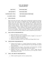
EMPLOYEE RIGHTS<br />
UNDER THE DAVIS-BACON ACT<br />
fOR LABORERS AND MECHANICS<br />
EMPLOYED ON fEDERAL OR fEDERALLY<br />
ASSISTED CONSTRUCTION PROjECTS<br />
THE UNITED STATES DEPARTMENT OF LABOR WAGE AND HOUR DIVISION<br />
PREVAILING<br />
WAGES<br />
OVERTIME<br />
ENFORCEMENT<br />
APPRENTICES<br />
PROPER PAY<br />
You must be paid not less than the wage rate listed in the Davis-Bacon<br />
Wage Decision posted with this Notice for the work you perform.<br />
You must be paid not less than one and one-half times your basic<br />
rate <strong>of</strong> pay for all hours worked over 40 in a work week. There are few<br />
exceptions.<br />
Contract payments can be withheld to ensure workers receive wages<br />
and overtime pay due, and liquidated damages may apply if overtime<br />
pay requirements are not met. Davis-Bacon contract clauses allow<br />
contract termination and debarment <strong>of</strong> contractors from future federal<br />
contracts for up to three years. A contractor who falsifies certified<br />
payroll records or induces wage kickbacks may be subject to civil or<br />
criminal prosecution, fines and/or imprisonment.<br />
Apprentice rates apply only to apprentices properly registered under<br />
approved Federal or State apprenticeship programs.<br />
If you do not receive proper pay, or require further information on the<br />
applicable wages, contact the Contracting Officer listed below:<br />
or contact the U.S. Department <strong>of</strong> Labor’s Wage and Hour Division. <br />
For additional information:<br />
1-866-4-USWAGE<br />
(1-866-487-9243) TTY: 1-877-889-5627<br />
WWW.WAGEHOUR.DOL.GOV<br />
U.S. Department <strong>of</strong> Labor Employment Standards Administration Wage and Hour Division<br />
WH 1321(Revised April 2009)
DIVISION 1 - GENERAL REQUIREMENTS<br />
SECTION 01010 - SUMMARY OF WORK:<br />
1.1 Location: The project site for Catholic War Veterans <strong>Park</strong> <strong>Service</strong> <strong>Center</strong><br />
<strong>Building</strong> <strong>Improvements</strong> and Renovations is located at 115 S. Mayberry Road in<br />
<strong>Mission</strong>, Texas.<br />
1.2 Approval <strong>of</strong> Working Surfaces: Any contractor performing work over the work <strong>of</strong><br />
other contractors shall notify the Architect <strong>of</strong> any unsatisfactory condition.<br />
Beginning <strong>of</strong> work by any contractor shall constitute the acceptance <strong>of</strong> the<br />
previous work.<br />
1.3 Checking Dimensions at Site: Before ordering any materials or doing any work,<br />
verify all measurements <strong>of</strong> the building and be responsible for the correctness <strong>of</strong><br />
them. No extras will be allowed for variations from drawings in existing<br />
conditions or for work performed under this contract. Any discrepancies found<br />
shall be submitted to the Architect for instruction before proceeding. The Section<br />
shall be enforced diligently.<br />
1.4 Cutting & Patching: No excessive cutting will be permitted, nor shall any<br />
structural members be cut without the approval <strong>of</strong> the Architect. Each contractor<br />
shall leave all chases and openings straight, true and <strong>of</strong> the proper size in his<br />
work as may be necessary for the proper installation <strong>of</strong> his and/or other<br />
contractor's work. After such work has been installed, he shall carefully fit<br />
around, close up, repair, patch and point up same as directed, to the entire<br />
satisfaction <strong>of</strong> the Architect.<br />
1.5 Cooperation: The General Contractor, all other contractors and all subcontractors<br />
shall coordinate their work with all adjacent work and shall cooperate<br />
with all other trades so as to facilitate the general progress <strong>of</strong> the work. Each<br />
trade shall afford all other trades every reasonable opportunity for installation <strong>of</strong><br />
their work and storage <strong>of</strong> their materials.<br />
1.6 Project Logbook: The project superintendent shall maintain a daily project<br />
logbook, indicating which sub-contractors were on the job, time <strong>of</strong> arrival, and the<br />
number <strong>of</strong> workers. Statements as to the daily progress shall be logged. This<br />
log book shall be made available to the Architect and shall be kept at the job site<br />
<strong>of</strong>fice.<br />
1.7 Inspection and Tests: Architect and his representative shall at all times have<br />
access to the work whether it is in preparation or progress. Provide proper and<br />
safe facilities for such access and inspection. Make all inspections and test in<br />
connection with this entire contract as required by the Architect. All material<br />
testing shall be paid for by the Testing Allowance and be done by an<br />
independent testing laboratory meeting the approval <strong>of</strong> the architect.<br />
1.8 Security: Provide security fencing in all work areas. See Temporary Facilities.<br />
2. ALLOWANCES:<br />
See Paragraph 4.8 <strong>of</strong> the General Conditions.<br />
2.1 Testing Allowance: A recognized, independent material testing laboratory,<br />
GENERAL REQUIREMENTS 1
selected by the Architect shall perform the necessary material testing services.<br />
Only material testing costs shall be borne by this TESTING ALLOWANCE. Any<br />
cost <strong>of</strong> retesting required due to failure <strong>of</strong> original tests to meet requirements<br />
standard shall be borne by the Contractor at no expense to the Owner. The<br />
General Contractor is expected to furnish invoices for work preformed to the<br />
Architect with every application and certificate for payment. Failure to do so, the<br />
General Contractor will not receive payment for the month submitted.<br />
TESTING ALLOWANCE: $5,000.00<br />
2.2 Betterment Allowance: Include the sum set forth below as a Betterment<br />
Allowance which will, if needed, be expended on Betterment to the Project, as<br />
directed in writing by approved change orders;<br />
BETTERMENT ALLOWANCE: $10,000.00<br />
SECTION 0110 - BID SCHEDULE<br />
1. BID SCHEDULE: All proposals and alternate bid items shall be subject to the<br />
General and Special Conditions and all other related sections <strong>of</strong> the specifications and<br />
requirements <strong>of</strong> the drawings. The Owner shall have the right to accept or reject any or<br />
all alternates.<br />
1.1 BASE BID: The Contractor shall state on the General Contract Bid Proposal<br />
under the Base Bid, the amount for all work, complete in all respects in<br />
accordance with plans and specifications, to construct Catholic War Veterans<br />
<strong>Park</strong> <strong>Service</strong> <strong>Center</strong> <strong>Building</strong> <strong>Improvements</strong> and Renovations. The scope <strong>of</strong><br />
work is defined in the plans and specifications.<br />
1.2 ALTERNATES: The Contractor shall state on his Bid Form, under each Alternate<br />
the amount to add to his bid to perform all work, complete in all respects, in<br />
accordance with the plans and specifications to construct work required by the<br />
Alternates.<br />
N/A<br />
SECTION 0120 - AS BUILT DRAWINGS:<br />
As the work proceeds, keep careful records <strong>of</strong> piping, electrical circuits, duct work and<br />
other concealed work whose installed location varies from that shown on plans. Furnish<br />
the Architect with one marked up set before final.<br />
SECTION 0130 - REPORTS:<br />
The Contractor will provide a written report to the Architect after each inspection<br />
conducted by the <strong>City</strong> Inspectors concerning their findings.<br />
SECTION 0140 - QUANTITIES & WARRANTIES:<br />
All guarantees and warranties expressed or implied shall be provided to the Architect in<br />
written form prior to final payment.<br />
SECTION 0150 - PICTURES:<br />
The Contractor will provide the Architect with sequence photographs showing the<br />
flashing in place prior to application <strong>of</strong> ro<strong>of</strong>. This is MANDATORY. Close-ups <strong>of</strong> all<br />
flashing are required.<br />
SECTION 0160 - CERTIFICATION OF CONSTRUCTION:<br />
The building contractor or construction manager shall certify in writing that the facility<br />
GENERAL REQUIREMENTS 3
has been constructed in accordance to the construction documents and its<br />
specifications.<br />
SECTION 0170 - CERTIFICATION OF NON-USE OF ASBESTOS PRODUCTS<br />
The General Contractor shall provide the Architect with written certification letters from<br />
all sub-contractors and suppliers that no asbestos products shall be use on this project.<br />
SECTION 0180 - SCOPE AND SEQUENCE OF CONSTRUCTION<br />
1.1 General:<br />
Time extensions shall be submitted for review on a monthly basis.<br />
The successful bidder shall under no circumstances leave this project unsecured or<br />
unprotected at any time during construction. The General Contractor is to refer to<br />
Section 01505 Temporary Facilities for any and all requirements required by this project.<br />
The General Contractor to provide all necessary precautions and safeguards during<br />
construction for protection <strong>of</strong> any visitor whom might visit the project site. The General<br />
Contractor shall provide in a neat format project monthly reports with photos showing<br />
progress <strong>of</strong> construction for their review.<br />
GENERAL REQUIREMENTS 3
SECTION 01340 - SUBMITTALS<br />
PART 1 - GENERAL<br />
RELATED DOCUMENTS:<br />
Drawings and general provisions <strong>of</strong> Contract, including General and Supplementary<br />
Conditions and other Division 1 Specifications, apply to work <strong>of</strong> this section.<br />
DESCRIPTION OF REQUIREMENTS:<br />
The types <strong>of</strong> submittal requirements for specified in this section including shop drawings,<br />
product data, samples and miscellaneous work related Submittals. Individual submittal<br />
requirements are specified in applicable sections for each unit <strong>of</strong> work. Refer to other<br />
Division 1 sections and other contract documents for requirements <strong>of</strong> administrative<br />
Submittals.<br />
Definitions: Work related Submittals <strong>of</strong> this section are categorized for convenience as<br />
follows:<br />
Shop drawings include specially prepared technical data for this project including<br />
drawings, diagrams; performance curves data sheets schedules, templates,<br />
patterns, reports, calculations, instructions, measurements and similar<br />
information not in standard printed form for general application to a range <strong>of</strong><br />
similar projects.<br />
Product data includes standard printed information on manufactured products<br />
that has not been specially prepared for this project, other than the designation <strong>of</strong><br />
selections from among available choices printed therein.<br />
Samples include both fabricated and un-fabricated physical examples <strong>of</strong><br />
materials, products and units <strong>of</strong> work; both as complete units and as smaller<br />
portions <strong>of</strong> units <strong>of</strong> work; either for limited visual inspection or (where indicated)<br />
for more detailed testing and analysis.<br />
Mock ups are special forms <strong>of</strong> samples, which are too large or otherwise<br />
inconvenient for handling in the manner specified for transmittal <strong>of</strong> sample<br />
Submittals.<br />
Miscellaneous Submittals related directly to the work (non administrative) include<br />
warranties, maintenance agreements, workmanship bonds, project photographs,<br />
survey data and reports, physical work records quality testing and certification<br />
reports, copies <strong>of</strong> industry standards, record drawings, field measurement data,<br />
operating and maintenance manuals, overrun stock, and similar information,<br />
devices and materials applicable to the work and not processed as shop<br />
drawings, product data or samples.<br />
GENERAL SUBMITTAL REQUIREMENTS:<br />
Scheduling: Where appropriate in administrative submittals, (listing <strong>of</strong> products,<br />
manufacturers, suppliers and sub-contractors, and in job progress schedule), show<br />
principal work related submittals and time requirements for coordination <strong>of</strong> submittal<br />
activity with related work in each instance.<br />
SUBMITTALS 01340 - 1
Listing: Prepare a separate listing; organized by related specification section number<br />
sequence, showing principal work related submittals and their initial submittal dates as<br />
required for coordination <strong>of</strong> the work. Submit listing within 45 days <strong>of</strong> date <strong>of</strong><br />
commencement <strong>of</strong> the work.<br />
Coordination and Sequencing: Coordinate preparation and processing <strong>of</strong> submittals with<br />
the performance <strong>of</strong> the work so that work will not be delayed by submittals. Coordinate<br />
and sequence different categories <strong>of</strong> submittals for same work, and for interfacing units<br />
<strong>of</strong> work, so that one will not be delayed for coordination <strong>of</strong> A/E's review with another.<br />
Preparation <strong>of</strong> Submittals: Provide permanent marking on each submittal to identify<br />
project, date, Contractor, subcontractor, Submittal name, and similar information to<br />
distinguish it from other submittals. Show Contractor’s executed review and approval<br />
markings and provide space for the Architect/Engineer's "Action" marking. Package each<br />
submittal appropriately for transmittal and handling. Submittals which are received from<br />
sources other than through Contractor's <strong>of</strong>fice will be returned by A/E "without action".<br />
SPECIFIC CATEGORY SUBMITTAL REQUIREMENTS:<br />
General: Except as otherwise indicated in the individual work sections, comply with the<br />
requirements specified herein for each indicated category <strong>of</strong> submittal. Provide and<br />
process intermediate submittals, where required between initial and final, similar to initial<br />
submittals.<br />
Shop Drawings: Provide newly prepared information, on reproducible sheets, with<br />
graphic information at accurate scale (except as otherwise indicated), with name <strong>of</strong><br />
preparer indicated (firm name). Show dimensions and not which are based on field<br />
measurement. Identify materials and products in the work shown. Indicate compliance<br />
with standards and special coordination requirements. Do not allow shop drawing copies<br />
without appropriate final "Action” markings by the Architect/Engineer to be used in<br />
connection with the work.<br />
Initial Submittal: Provide one correctable translucent reproducible print and five blue line<br />
or black line prints: the reproducible will be returned.<br />
Product Data: Collect required data into one submittal for each unit <strong>of</strong> work or system;<br />
and mark each copy to show which choices and options are applicable to project.<br />
Include manufacturer's standard printed recommendations for application and use,<br />
compliance with standards, application <strong>of</strong> labels and seals, notation <strong>of</strong> field<br />
measurements which have been checked, and special coordination requirements.<br />
Maintain one set <strong>of</strong> product data (for each submittal) at project site, available for<br />
reference by Architect/Engineer and others.<br />
Submittals: Do not submit product data, or allow its use on the project, until compliance<br />
with requirements <strong>of</strong> contract documents has been confirmed by Contractor. Submittal is<br />
for information and record, unless otherwise indicated.<br />
Initial submittal is final submittal unless returned promptly by Architect/Engineer, marked<br />
with an "Action” which indicates an observed non-compliance. Submit 3 copies plus 3<br />
additional copies (which will be returned) where required for maintenance manuals.<br />
Samples: Provide units identical with final condition <strong>of</strong> proposed materials or products for<br />
SUBMITTALS 01340 - 2
the work. Include "range" samples (not less than 3 units) where unavoidable variations<br />
must be expected, and described or identify variations between units <strong>of</strong> each set.<br />
Provide full set <strong>of</strong> optional samples where Architect's/Engineer's selection is required.<br />
Prepare samples to match Architect's/Engineer's sample where so indicated. Include<br />
information with each sample to show generic description, source or product name and<br />
manufacturer, limitations, and compliance with standards. Samples are submitted for<br />
review and confirmation <strong>of</strong> color, pattern, texture and "kind" by Architect/Engineer.<br />
Architect/Engineer will not "test" samples (except as otherwise indicated) for compliance<br />
with other requirements, which are therefore the exclusive responsibility <strong>of</strong> Contractor.<br />
Submittal: Provide a single set <strong>of</strong> samples for<br />
Architect's/Engineer's review and "Action".<br />
Mock Ups and similar samples specified in individual work sections recognized as a<br />
special type <strong>of</strong> sample. Comply with requirements for "samples" to greatest extent<br />
possible, and process transmittal forms to provide a record <strong>of</strong> activity.<br />
Inspection and Test Reports: Classify each as either "shop drawings" or "product data"<br />
depending upon whether report is uniquely prepared for project, or a standard<br />
publication <strong>of</strong> workmanship control testing at point <strong>of</strong> production and process<br />
accordingly.<br />
Warranties: Refer to "Products" section for specific general requirements on warranties,<br />
product/workmanship bonds and maintenance agreements. In addition to copies desired<br />
for the Contractor's use, furnish 2 executed copies except furnish 2 additional<br />
(conformed) copies where required for maintenance manuals.<br />
Closeout Submittals: Refer to section "closeout" and to individual work sections for<br />
specific requirements on submittal <strong>of</strong> closeout information, materials, tools, and similar<br />
items.<br />
Record Documents Copies: Furnish one set.<br />
Operating and Maintenance Data: Furnish 2 bound copies.<br />
Materials and Tools: Refer to individual work sections <strong>of</strong> for required quantities <strong>of</strong> spare<br />
parts, extra and overrun stock, maintenance tools and devices, keys, and similar<br />
physical units to be submitted.<br />
General Distribution: Provide additional distribution <strong>of</strong> submittals (not included in<br />
foregoing copy submittal requirements) to subcontractors, suppliers, fabricators,<br />
installers, governing authorities, and others as necessary for the proper performance <strong>of</strong><br />
the work. Include such additional copies in transmittal to the Architect/Engineer where<br />
the submittals are required to receive "Action” marking before final distribution. Record<br />
submittal distributions on transmittal forms.<br />
ACTION ON SUBMITTALS<br />
Architect/Engineer's Action: Where action and return is required or requested, the<br />
Architect/Engineer will review each submittal, mark with “Action", and where possible<br />
return within 2 weeks <strong>of</strong> receipt.<br />
SUBMITTALS 01340 - 3
Where the submittal must be held for coordination, Contractor will be so advised by A/E<br />
without delay.<br />
Final Unrestricted Release: Work may proceed, provided it complies with the contract<br />
documents, when submittal is returned with the following:<br />
Marking: "Accepted".<br />
Marking: "Approved".<br />
Final But Restricted Release: Work may proceed, provided it complies with notations<br />
and corrections on submittal and with contract documents, when submittal is returned<br />
with the following:<br />
Marking: "Accepted as Noted".<br />
Marking: "Approved as Noted".<br />
Returned for Resubmittal: Do not proceed with work. Revise submittal in accordance<br />
with notations thereon, and resubmit without delay to obtain a different action marking.<br />
Do not allow submittals with the following marking (or unmarked submittals where a<br />
marking is required) to be used in connection with performance <strong>of</strong> the work:<br />
Marking: "Not Accepted, Resubmit".<br />
Marking: "Disapproved, Resubmit".<br />
Other Action: Where the submittal is returned, for other reasons, with<br />
Architect/Engineer's explanation included, it will be marked as follows:<br />
Marking: "Action Not Required".<br />
Marking: "No Action".<br />
Action Stamp: Architect's/Engineer's action stamp, for use on submittals to be returned<br />
to Contractor, is self explanatory as marked.<br />
PART 2 - PRODUCTS (Not Applicable).<br />
PART 3 - EXECUTION (Not Applicable).<br />
END OF SECTION 01340<br />
SUBMITTALS 01340 - 4
SECTION 01505 - -TEMPORARY FACILITIES<br />
PART 1 - GENERAL<br />
RELATED DOCUMENTS:<br />
Drawings and general provisions <strong>of</strong> the Contract, including General and Supplementary<br />
Conditions and other Division 1 Specification sections, apply to the work <strong>of</strong> this section.<br />
DESCRIPTION OF REQUIREMENTS:<br />
Definitions: Specific administrative and procedural minimum actions are specified in this<br />
section, as extensions <strong>of</strong> provisions in General Conditions and other contract<br />
documents. These requirements have been included for special purposes as indicated.<br />
Nothing in this section is intended to limit types and amounts <strong>of</strong> temporary work<br />
required, and no omission from this section will be recognized as an indication by<br />
Architect or Engineer that such temporary activity is not required for successful<br />
completion <strong>of</strong> the work and compliance with requirements <strong>of</strong> contract documents.<br />
Provisions <strong>of</strong> this section are applicable to, but not by way <strong>of</strong> limitation, utility services,<br />
construction facilities, support facilities, security/protection provisions, and support<br />
facilities.<br />
QUALITY ASSURANCE:<br />
General: In addition to compliance with governing regulations and rules/recommendation<br />
<strong>of</strong> franchised utility companies, comply with specific requirements indicated and with<br />
applicable local industry standards for construction work (published recommendations by<br />
local consensus "building councils").<br />
ANSI Standards: Comply with applicable provisions <strong>of</strong> ANSI Al Series standards on<br />
construction safety, including A.10.3, A.10.4, A10.5, A10.6, A10.7, A10.8, A10.9,<br />
A10.10, A10.11, A10.12, A10.13, A10.14, A10.15, A10.17, A10.18, A10.20, and A10.22.<br />
NFPA Code" Comply with NFPA Code 241 "<strong>Building</strong> Construction and Demolition<br />
Operations."<br />
JOB CONDITIONS:<br />
General: Establish and initiate use <strong>of</strong> each temporary facility at time first reasonably<br />
required for proper performance <strong>of</strong> the work. Terminate use and remove facilities at<br />
earliest reasonable time, when no longer needed or when permanent facilities have, with<br />
authorized use, replaced the need.<br />
Conditions <strong>of</strong> Use: Install, operate, maintain and protect temporary facilities in a manner<br />
and at locations which will be safe, non hazardous, sanitary and protective <strong>of</strong> persons<br />
and property, and free <strong>of</strong> deleterious effects.<br />
PART 2 AND 3 - PRODUCTS AND EXECUTION<br />
TEMPORARY UTILITY SERVICES:<br />
The types <strong>of</strong> services required include, but not by way <strong>of</strong> limitation, water, sewerage,<br />
surface drainage, electrical power and telephones. Where possible and reasonable,<br />
connect to existing franchised utilities for required services; and comply with service<br />
TEMPORARY FACILITIES 01505 - 1
companies' recommendations on materials and methods, or engage service companies<br />
to install services. Locate and relocate services (as necessary) to minimize interference<br />
with construction operations.<br />
TEMPORARY CONSTRUCTION FACILITIES:<br />
The types <strong>of</strong> temporary construction facilities required include, but not by way <strong>of</strong><br />
limitation, water distribution, drainage, enclosure <strong>of</strong> work, heat, ventilation, electrical<br />
power distribution, lighting, hoisting facilities, stairs, ladders, and roads. Provide facilities<br />
reasonably required to perform construction operations properly and adequately.<br />
Water Distribution: Provide hose lengths sufficient to reach entire area <strong>of</strong> construction<br />
work, not less than 3/4" hose size. Prevent freezing <strong>of</strong> water distribution by either prompt<br />
drainage after each use, or by suitable protection.<br />
Electrical Power: Provide weatherpro<strong>of</strong>, grounded, power distribution system sufficient to<br />
accommodate construction operations requiring power, use <strong>of</strong> power tools, electrical<br />
heating, lighting, and start up testing <strong>of</strong> permanent electric powered equipment prior to<br />
its permanent connection to electrical system. Provide overload protection. Locate<br />
multiple outlets (not less than 4 gang boxes) at each story <strong>of</strong> construction, spaced so<br />
that entire area <strong>of</strong> construction can be reached by power tools on a single extension<br />
cord <strong>of</strong> 100' maximum length.<br />
Supply power for electric welding, if any, from either temporary power distribution<br />
system or by engine driven power generator sets, at Contractor's option.<br />
Lighting: Provide sufficient temporary lighting to ensure proper workmanship<br />
everywhere; by combined use <strong>of</strong> daylight, general lighting, and portable plug in task<br />
lighting. Provide general lighting with local switching which will enable energy<br />
conservation during periods <strong>of</strong> varying activity (work in progress, traffic only security<br />
check, lock up, etc.).<br />
Provide uniformly spaced general lighting equivalent to not less than one 200<br />
watt incandescent lamp per 1000 sq. ft. <strong>of</strong> floor area, and one 100 watt lamp per<br />
50' <strong>of</strong> corridor and per flight <strong>of</strong> stairs.<br />
Access Provisions: Provide ramps, stairs, ladders and similar temporary access<br />
elements as reasonably required to perform the work and facilitate its inspection during<br />
installation. Comply with reasonable requests <strong>of</strong> governing authorities performing<br />
inspections. When permanent stairs are available for access during construction, cover<br />
finished surfaces with sufficient protection to ensure freedom from damage and<br />
deterioration at time <strong>of</strong> substantial completion.<br />
SECURITY/PROTECTION PROVISION:<br />
The types <strong>of</strong> temporary security and protection provision required include, but not by<br />
way <strong>of</strong> limitation, fire protection, barricades, fencing (wire), warning signs/lights, and<br />
similar provision intended to minimize property losses, personal injuries and claims for<br />
damages at project site.<br />
Fire Extinguishers: Provide types, sizes, numbers and locations as would be reasonably<br />
effective in extinguishing fires during early stages, by personnel at project site. Provide<br />
Type A extinguishers at locations <strong>of</strong> low potential for either electrical or grease oil<br />
flammable liquids fires; provide Type ABC dry chemical extinguishers at other locations;<br />
TEMPORARY FACILITIES 01505 - 2
comply with recommendations <strong>of</strong> NFPA No. 10. Post warning and quick instructions at<br />
each extinguisher location, and instruct proper use <strong>of</strong> extinguishers and other available<br />
facilities at project site. Post local fire department call number on each telephone<br />
instrument at project site.<br />
Permanent Fire Protection: Complete each fire protection facility at earliest<br />
reasonable date, make ready for emergency use, and instruct personnel at site<br />
on availability and proper use.<br />
<strong>Building</strong> Enclosure and Lockup: At earliest possible date, secure building against<br />
unauthorized entrance at times when personnel are not working.<br />
TEMPORARY SUPPORT FACILITIES:<br />
The types <strong>of</strong> temporary support facilities required include, but not by way <strong>of</strong> limitation,<br />
field <strong>of</strong>fices, storage sheds, fabrication sheds, sanitary facilities, drinking water, first aid<br />
facilities, bulletin board, private telephones, project identification signs, clean up<br />
facilities, waste disposal service, and similar miscellaneous general services, all as may<br />
be reasonably required for pr<strong>of</strong>icient performance <strong>of</strong> the work and accommodation <strong>of</strong><br />
personnel at the site including Owner's and Architect's/Engineer's personnel.<br />
Discontinue and remove temporary support facilities, and make incidental similar use <strong>of</strong><br />
permanent work <strong>of</strong> the project, only when and in manner authorized by<br />
Architect/Engineer; and, if not otherwise indicated, immediately before time <strong>of</strong><br />
substantial completion. Locate temporary support facilities for convenience <strong>of</strong> users, and<br />
for minimum interference with construction activities.<br />
Contractor's Field Offices: Provide adequate <strong>of</strong>fice space for field <strong>of</strong>fice personnel plus<br />
one spare work station for incidental use by subcontractor's personnel, suitably finished,<br />
furnished, equipped and conditioned.<br />
Sanitary Facilities: At contractor's option, provide either piped (wet) toilets facilities or<br />
self contained toilet units <strong>of</strong> type acceptable to governing authorities, adequate (at all<br />
stages <strong>of</strong> construction) for use <strong>of</strong> personnel at job site. Provide separate facilities for<br />
male and female personnel when both sexes are working (in any capacity) at project<br />
site.<br />
Project Identification Sign: At locations(s) shown on site plans provide project<br />
identification sign complying with sketch/data sheet included at end <strong>of</strong> this section.<br />
Engage an experienced sign painter to paint graphics on sign as indicated. Construct<br />
sign <strong>of</strong> treated wood framing and posts, and 3/4" plywood panels <strong>of</strong> exterior type Grade<br />
B C sanded 2 sides.<br />
END OF SECTION 01505<br />
TEMPORARY FACILITIES 01505 - 3
SECTION 01605 - PRODUCTS AND SUBSTITUTIONS<br />
PART 1 - GENERAL<br />
RELATED DOCUMENTS:<br />
Drawings and general provisions <strong>of</strong> Contract, including General and Supplementary<br />
Conditions and other Division 1 Specification sections, apply to work <strong>of</strong> this section.<br />
DESCRIPTION OF REQUIREMENTS:<br />
Definitions: "Products" is defined to include purchased items for incorporation into the<br />
work, regardless <strong>of</strong> whether specifically purchased for project or taken from Contractor's<br />
stock <strong>of</strong> previously purchased products. "Materials", is defined as products which must<br />
be substantially cut, shaped, worked, mixed, finished, refined or otherwise fabricated,<br />
processed, installed or applied to form units <strong>of</strong> work. "Equipment" is defined as products<br />
with operational parts, regardless <strong>of</strong> whether motorized or manually operated, and<br />
particularly including products with service connections (wiring, piping, etc.). Definitions<br />
in this paragraph are not intended to negate the meaning <strong>of</strong> other terms used in contract<br />
documents, including "specialties," "systems," "structure," "finishes," "accessories,"<br />
"furnishings," "special construction,” and similar terms, which are self explanatory and<br />
have recognized meanings in the construction industry.<br />
Substitutions: The requirements for substitutions do not apply to specified Contractor<br />
options on products and construction methods. Revisions to contract documents, where<br />
requested by Owner, Architect or Engineer, are "changes" not "substitutions."<br />
Substitutions requested during bidding period, which have been accepted prior to<br />
Contract Date, are included in contract documents and are not subject to requirements<br />
for substitutions as specified herein. Contractor's determination <strong>of</strong> an compliance with<br />
governing regulations and orders issued by governing authorities do not constitute<br />
"substitutions;" and do not constitute a basis for change orders, except as provided for in<br />
contract documents. Otherwise, Contractor's requests for changes in products,<br />
materials and methods <strong>of</strong> construction required by contract documents are considered<br />
requests for "substitutions," and are subject to requirements here<strong>of</strong>.<br />
Standards: Refer to Division 1 section "Definitions and Standards" for applicability <strong>of</strong><br />
industry standards to products <strong>of</strong> project, and for acronyms used in text <strong>of</strong> specification<br />
sections.<br />
QUALITY ASSURANCE:<br />
Source Limitations: To the greatest extent possible, for each unit <strong>of</strong> work, provide<br />
products, materials or equipment <strong>of</strong> a singular generic kind and from a single source.<br />
Compatibility <strong>of</strong> Options: Where more than one choice is available as options for<br />
Contractor's selection <strong>of</strong> a product or material, select an option which is compatible with<br />
other products and materials already selected (which may have been from among<br />
options for those other products and materials). Total compatibility among options is not<br />
assured by limitations within contract documents, but must be provided by Contractor.<br />
Compatibility is a basic general requirement <strong>of</strong> product/material selections.<br />
SUBMITTALS:<br />
Requests for Substitutions: Submit 3 copies, fully identified for product or method being<br />
PRODUCTS AND SUBSTITUTIONS 01605 -1
eplaced by substitution, including related specification section and drawing number(s),<br />
and fully documented to show compliance with requirements for substitutions. Include<br />
product data/drawings, description <strong>of</strong> methods, samples where applicable, Contractor's<br />
detailed comparison <strong>of</strong> significant qualities between specified item and proposed<br />
substitution, statement <strong>of</strong> effect on construction time and coordination with other affected<br />
work, cost information or proposal, and Contractor's statement to the effect that<br />
proposed substitution will result in overall work equal to or better than work originally<br />
indicated.<br />
PRODUCT DELIVER STORAGE HANDLING:<br />
General: Deliver, handle and store products in accordance with manufacturer's<br />
recommendations and by methods and means which will prevent damage, deterioration,<br />
and loss including theft. Control delivery schedules to minimize long term storage <strong>of</strong><br />
products at site and overcrowding <strong>of</strong> construction spaces. In particular, provide<br />
delivery/installation coordination to ensure minimum holding or storage times for<br />
products recognized to be flammable, hazardous, easily damaged, or sensitive to<br />
deterioration, theft and other sources <strong>of</strong> loss.<br />
WARRANTIES (GUARANTEES):<br />
Categories <strong>of</strong> Specific Warranties: Warranties on the work are in several categories,<br />
including those <strong>of</strong> General Conditions, and including (but not necessarily limited to) the<br />
following specific categories related to individual units <strong>of</strong> work specified in sections <strong>of</strong><br />
Divisions 2 through 16 <strong>of</strong> these specifications:<br />
Special Project Warranty (Guarantee): A warranty specifically written and signed by<br />
Contractor for a defined portion <strong>of</strong> the work; and, where required, countersigned by<br />
subcontractor, installer, manufacturer or other entity engaged by Contractor.<br />
Specified Product Warranty: A warranty which is required by contract documents, to be<br />
provided for a manufactured product incorporated into the work; regardless <strong>of</strong> whether<br />
manufacturer has published a similar warranty without regard for specific incorporation<br />
<strong>of</strong> a product into the work, or has written and executed a special product warranty as a<br />
direct result <strong>of</strong> contract document requirements.<br />
Coincidental Product Warranty: A warranty which is not specifically required by contract<br />
documents (other than as specified in this Section); but which is available on a product<br />
incorporated into the work, by virtue <strong>of</strong> the fact that manufacturer <strong>of</strong> product has<br />
published warranty in connection with purchases and uses <strong>of</strong> product without regard for<br />
specific applications except as otherwise limited by terms <strong>of</strong> warranty.<br />
Refer to individual sections <strong>of</strong> Divisions 2 through 16 for the determination <strong>of</strong> units <strong>of</strong><br />
work which are required to be specifically or individually warranted, and for the specific<br />
requirements and terms <strong>of</strong> those warranties (or guarantees).<br />
General Limitations: It is recognized that specific warranties are intended primarily to<br />
protect Owner against failure <strong>of</strong> the work to perform as required, and against deficient,<br />
defective and faulty materials and workmanship, regardless <strong>of</strong> sources. Except as<br />
otherwise indicated, specific warranties do not cover failures in the work which result<br />
from: 1.) Unusual and abnormal phenomena <strong>of</strong> the elements, 2.) The Owner's misuse,<br />
maltreatment or improper maintenance <strong>of</strong> the work, 3.) Vandalism after time <strong>of</strong><br />
substantial completion, or 4.) Insurrection or acts <strong>of</strong> aggression including war.<br />
PRODUCTS AND SUBSTITUTIONS 01605 -2
Related Damages and Losses: In connection with Contractor's correction <strong>of</strong> warranted<br />
work which has failed, remove and replace other work <strong>of</strong> project which has been<br />
damaged as a result <strong>of</strong> such failure, or must be removed and replaced to provide access<br />
for correction <strong>of</strong> warranted work.<br />
Consequential Damages: Except as otherwise indicated or required by governing<br />
regulation, special project warranties and product warranties are not extended to cover<br />
damage to building contents (other than work <strong>of</strong> Contract) which occurs as a result <strong>of</strong><br />
failure <strong>of</strong> warranted work.<br />
Reinstatement <strong>of</strong> Warranty Period: Except as otherwise indicated, when work covered<br />
by a special project warranty or product warranty has failed and has been corrected by<br />
replacement or restoration, reinstate warranty by written endorsement for the following<br />
time period, starting on date <strong>of</strong> acceptance <strong>of</strong> replaced or restored work.<br />
A period <strong>of</strong> time is equal to original warranty period <strong>of</strong> time.<br />
Replacement Cost, Obligations: Except as otherwise indicated, costs <strong>of</strong> replacing or<br />
restoring failing warranted units or products is Contractor's obligation, without regard for<br />
whether Owner has already benefited from use through a portion <strong>of</strong> anticipated useful<br />
service lives.<br />
Rejection <strong>of</strong> Warranties: Owner reserves the right, at time <strong>of</strong> substantial completion or<br />
thereafter, to reject coincidental product warranties submitted by Contractor, which in<br />
opinion <strong>of</strong> Owner tend to detract from or confuse interpretation <strong>of</strong> requirements <strong>of</strong><br />
contract documents.<br />
Contractor's Procurement Obligations: Do not purchase, subcontract for, or allow others<br />
to purchase or sub subcontract for materials or units <strong>of</strong> work for materials or units <strong>of</strong><br />
work for project where a special project warranty, specified product warranty,<br />
certification or similar commitment is required, until it has been determined that entities<br />
required to countersign such commitments are willing to do so.<br />
Specific Warranty Forms: Where a special project warranty (guarantee) or specified<br />
project warranty is required, prepare a written document to contain terms and<br />
appropriate identification, ready for execution by required parties. Submit draft to Owner<br />
(through Architect/Engineer) for approval prior to final executions.<br />
PART 2 PRODUCTS<br />
GENERAL PRODUCT COMPLIANCES:<br />
General: The compliance requirements, for individual products as indicated in contract<br />
documents, are multiple in nature and may include generic, descriptive, proprietary,<br />
performance, prescriptive, compliance with standards, compliance with codes,<br />
conformance with graphic details and other similar forms and methods <strong>of</strong> indicating<br />
requirements, all <strong>of</strong> which must be complied with. Also "allowances" and similar<br />
provisions <strong>of</strong> contract documents will have a bearing on selection process.<br />
Procedures for Selecting Products: Contractor's options for selecting products<br />
are limited by contract document requirements, and governing regulations, and<br />
are not controlled by industry and governing regulations, and are not controlled<br />
PRODUCTS AND SUBSTITUTIONS 01605-3
y industry traditions or procedures experienced by Contractor on previous<br />
construction projects.<br />
Required procedures include, but are not necessarily limited to, the following for various<br />
indicated methods <strong>of</strong> specifying:<br />
Single Product/Manufacturer Name: Provide product indicated, except advice<br />
Architect/Engineer before proceeding, where known that named product is not a feasible<br />
or acceptable selection.<br />
Two or More Product/Manufacturer Names: Provide one <strong>of</strong> the named products, at<br />
Contractor's option; but excluding products which do not comply with requirements. Do<br />
not provide or <strong>of</strong>fer to provide an unnamed product, except where none <strong>of</strong> named<br />
products comply with requirements or are a feasible selection; advise Architect/Engineer<br />
before proceeding.<br />
"Or Equal": Where named products in specifications text are accompanied by the term<br />
"or equal", or other language <strong>of</strong> similar effect, comply with those contract document<br />
provisions concerning "substitutions" for obtaining Architect/Engineer's approval (by<br />
change order) to provide an unnamed product. This product must meet or exceed the<br />
original specified product specifications.<br />
"Named", except as otherwise indicated, is defined to mean manufacturer's name for<br />
product, as recorded in published product literature, <strong>of</strong> latest issue as <strong>of</strong> date <strong>of</strong> contract<br />
documents. Refer requests to use products <strong>of</strong> a later (or earlier) model to<br />
Architect/Engineer's for acceptance before proceeding.<br />
Standards, Codes and Regulations: Where only compliance with an imposed standard,<br />
code or regulation is required, selection from among products which comply with<br />
requirements including those standards, codes and regulations, is Contractor's option.<br />
Performance Requirements: Provide products which comply with specific performances<br />
indicated, and which are recommended by manufacturer (in published product literature<br />
or by individual certification) for application indicated. Overall performance <strong>of</strong> a product<br />
is implied where product is specified with only certain specific performance<br />
requirements.<br />
Prescriptive Requirements: Provide products which have been produced in accordance<br />
with prescriptive requirements, using specified ingredients and components, and<br />
complying with specified requirements for mixing, fabricating, curing, finishing, testing<br />
and similar operations in manufacturing process.<br />
SUBSTITUTIONS:<br />
Conditions: Contractor's request for substitution will be received and considered when<br />
extensive revisions to contract documents are not required and changes are in keeping<br />
with general intent <strong>of</strong> contract documents; when timely, fully documented and properly<br />
submitted; and when one or more <strong>of</strong> following conditions is satisfied, all as judged by<br />
Architect/Engineer. Otherwise, requests will be returned without action except to record<br />
non compliance with these requirements.<br />
Where required product, material or method cannot be provided in a manner which is<br />
compatible with other materials <strong>of</strong> the work, or cannot be properly coordinated therewith,<br />
or cannot be warranted as required, or cannot be used without adversely affecting<br />
Owner's insurance coverage on completed work, or will encounter other substantial non<br />
compliance which are not possible to otherwise overcome except by making requested<br />
PRODUCTS AND SUBSTITUTIONS 01605-4
substitution, which Contractor thereby certifies to overcome such non compatibility, non<br />
coordination, non warranty, non insurability or other non compliance as claimed.<br />
Work Related Submittals: Contractor's submittal <strong>of</strong> (and Architect/Engineer's<br />
acceptance <strong>of</strong>) shop drawings, product data or samples which relate to work not<br />
complying with requirements <strong>of</strong> contract documents, does not constitute an acceptable<br />
or valid request for a substitution, nor approval there<strong>of</strong>.<br />
GENERAL PRODUCT REQUIREMENTS:<br />
General: Provide products which comply with requirements, and which are undamaged<br />
and unused at time <strong>of</strong> installation, and which are complete with accessories, trim, finish,<br />
safety guards and other devices and details needed for a complete installation and for<br />
intended use and effect.<br />
Standard Products: Where available, provide standard products <strong>of</strong> types which have<br />
been produced and used previously and successfully on other projects and in similar<br />
applications.<br />
Nameplates: Except as otherwise indicated for required approval labels, and operating<br />
data, do not permanently attach or imprint manufacturer's or producer's nameplates or<br />
trademarks on exposed surfaces <strong>of</strong> products which will be exposed to view either in<br />
occupied spaces or on exterior <strong>of</strong> the work.<br />
Labels: Locate required labels and stamps on a concealed surface or, where required<br />
for observation after installation, on an accessible surface which, in occupied spaces, is<br />
not conspicuous.<br />
Equipment Nameplates: Provide permanent nameplate on each item <strong>of</strong> service<br />
connected or poser operated equipment. Indicate manufacturer, product name, model<br />
number, serial number, capacity, speed, ratings and similar essential operating data.<br />
Locate nameplates on an easily accessed surface which, in occupied spaces, is not<br />
conspicuous.<br />
PART 3 EXECUTION (not applicable)<br />
END OF SECTION 01605<br />
PRODUCTS AND SUBSTITUTIONS 01605 -5
SECTION 01705 - PROJECT CLOSEOUTS<br />
PART 1 - GENERAL<br />
RELATED DOCUMENTS:<br />
Drawings and general provisions <strong>of</strong> Contract, including General and Supplementary<br />
Conditions and other Division 1 Specification sections, apply to work <strong>of</strong> this section.<br />
DESCRIPTION OF REQUIREMENTS:<br />
Definitions: Closeout is hereby defined to include general requirements near the end <strong>of</strong><br />
the Contract Time, in preparation for final acceptance, final payment, normal termination<br />
<strong>of</strong> contract, occupancy by Owner and similar actions evidencing completion <strong>of</strong> the work.<br />
Specific requirements for individual units <strong>of</strong> work are specified in sections <strong>of</strong> Divisions 2<br />
through 16. Time <strong>of</strong> closeout is directly related to “Substantial Completion", and<br />
therefore may be either a single time period for entire work which have been certified as<br />
substantially complete at different dates. That time variation (if any) shall be applicable<br />
to other provisions <strong>of</strong> this section.<br />
PREREQUISITES TO SUBSTANTIAL COMPLETION:<br />
General: Prior to requesting the Architect/Engineer's inspection for certification <strong>of</strong><br />
substantial completion, (for either the entire work or for portions there<strong>of</strong>), complete the<br />
following and list known exceptions in the request:<br />
Submit specific warranties, workmanship/maintenance bonds, maintenance agreements,<br />
final certifications and similar documents.<br />
Obtain and submit releases enabling Owner’s full, unrestricted use <strong>of</strong> the work and<br />
access to services and utilities (where required), include occupancy permits, operating<br />
certificates, and similar releases.<br />
Deliver tools, spare parts, extra stocks <strong>of</strong> materials, and similar physical items to the<br />
Owner.<br />
Make final changeover <strong>of</strong> locks and transmit the keys to the Owner, and advise the<br />
Owner's personnel <strong>of</strong> change over in security provisions.<br />
Complete start up testing <strong>of</strong> systems, and instructions <strong>of</strong> the Owner’s operating and<br />
maintenance personnel. Discontinue or change over and remove temporary facilities and<br />
services from the project site, along with construction tools and facilities, mock ups, and<br />
similar elements.<br />
Complete final cleaning up requirements, including touch up <strong>of</strong> painting <strong>of</strong> marred<br />
surfaces.<br />
Inspection Procedures: Upon receipt <strong>of</strong> the Contractor's request Architect/Engineer will<br />
either proceed with inspection or advise Contractor <strong>of</strong> unfilled prerequisites. Following<br />
the initial inspection, the Architect/Engineer will either prepare the certificate <strong>of</strong><br />
substantial completion, or will advise the Contractor <strong>of</strong> work which must be performed<br />
prior to the issuance <strong>of</strong> certificate; and repeat the inspection when requested and when<br />
assured that the work has been substantially completed. Results <strong>of</strong> the completed<br />
PROJECT CLOSEOUT 01705 - 1
inspection will form the initial "punch list" for final acceptance.<br />
PREREQUISITES TO FINAL ACCEPTANCE:<br />
General: Prior to requesting Architect/Engineer's final inspection for certification <strong>of</strong> final<br />
acceptance, and final payment, as required by the General Conditions, complete the<br />
following and list known exceptions, (if any), in request.<br />
Submit the final payment request with final releases and supporting documentation not<br />
previously submitted and accepted. Include certificates <strong>of</strong> insurance for products and<br />
completed operations where required.<br />
Submit an updated final statement, accounting for final additional changes to the<br />
Contract Sum.<br />
Submit certified copy <strong>of</strong> the Architect/Engineer’s final punch list <strong>of</strong> itemized work to be<br />
completed or corrected, stating that each item has been completed or otherwise<br />
resolved for acceptance and has been endorsed and dated by the Architect.<br />
Submit consent <strong>of</strong> surety.<br />
Re-inspection Procedure: Upon receipt <strong>of</strong> the Contractor's notice that the work has been<br />
completed, including punch list items resulting from earlier inspections, and excepting<br />
incomplete, items delayed because <strong>of</strong> acceptable circumstances, the Architect/Engineer<br />
will re-inspect the work.<br />
Upon completion <strong>of</strong> re-inspection, the Architect/Engineer will either prepare a certificate<br />
<strong>of</strong> final acceptance, or will advise the Contractor <strong>of</strong> work that is incomplete or obligations<br />
not fulfilled, as required for final acceptance. If necessary, procedure will be repeated.<br />
RECORD DOCUMENT SUBMITTALS:<br />
General: Specific requirements for record documents are indicated in individual sections<br />
<strong>of</strong> these specifications. Other requirements are indicated in the General Conditions.<br />
General submittal requirements are indicated in the "Submittals" sections. Do not use<br />
record documents for construction purposes; protect from deterioration and loss in a<br />
secure, fire resistive location; provide access to record documents for<br />
Architect/Engineer's reference during normal working hours.<br />
Record Drawings: Maintain a white print set (blue line or white prints <strong>of</strong> contract<br />
drawings and shop drawings in a clean, undamaged condition with mark up <strong>of</strong> actual<br />
installations which vary substantially from the work as originally shown. Mark whichever<br />
drawing is most capable <strong>of</strong> showing the actual "field" condition fully and accurately;<br />
however, where shop drawings are used for mark up, record a cross reference at the<br />
corresponding location on the working drawings. Mark with red erasable pencil and,<br />
where feasible, use other colors to distinguish between variations in separate categories<br />
<strong>of</strong> work. Mark up new information which is recognized to be <strong>of</strong> importance to Owner, but<br />
was for some reason not shown on either contract drawings or shop drawings. Give<br />
particular attention to concealed work that would be difficult to measure and record at a<br />
later date. Note related change order numbers where applicable. Organize record<br />
drawing sheets into manageable sets, bind with durable paper cover sheets, and print<br />
suitable titles, dates and other identification on cover <strong>of</strong> each set.<br />
PROJECT CLOSEOUT 01705 - 2
Record Specifications: Maintain one copy <strong>of</strong> specifications, including addenda, change<br />
orders and similar modifications issued in printed form during construction, and mark up<br />
variations (<strong>of</strong> substance) in the actual work in comparison with the text <strong>of</strong> the<br />
specifications and modifications as issued. Give particular attention to substitutions,<br />
selection <strong>of</strong> options and similar information on work where it is concealed or cannot<br />
otherwise be readily discerned at a later date by direct observation. Note related record<br />
drawing information and product data, where applicable. Upon completion <strong>of</strong> mark up,<br />
submit to Architect/Engineer for Owner’s records.<br />
Record Product Data: Maintain one copy <strong>of</strong> each product data submittal, and mark up<br />
significant variations in actual work in performed in comparison with the submitted<br />
information. Include both variations in product as delivered to site, and variations from<br />
the manufacturer's instructions and recommendations for installation. Give particular<br />
attention to concealed products and portions <strong>of</strong> the work which cannot otherwise be<br />
readily discerned at a later date by direct observation. Note related change orders and<br />
mark up <strong>of</strong> record drawings and specifications. Upon completion <strong>of</strong> mark up, submit<br />
complete set to Architect/Engineer for the Owners' records.<br />
Record Sample Submittal: Immediately prior to date(s) <strong>of</strong> substantial completion, the<br />
Architect/Engineer (and including Owner's personnel where desired) will meet with<br />
Contractor at site, and will determine which (if any) <strong>of</strong> submitted samples maintained by<br />
Contractor during progress <strong>of</strong> the work, are to be transmitted to the Owner for record<br />
purposes. Comply with Architect/Engineer's instruction for packaging, identification<br />
marking, and delivery to the Owner's sample storage area.<br />
Miscellaneous Record Submittals: Refer to other sections <strong>of</strong> these specifications for<br />
requirements <strong>of</strong> miscellaneous record keeping and submittals in connection with the<br />
actual performance <strong>of</strong> the work. Immediately prior to the date(s) <strong>of</strong> substantial<br />
completion, complete miscellaneous records and place in good order, properly identified<br />
and bound or filed, ready for continued use and reference. Submit to the<br />
Architect/Engineer for the Owner's records.<br />
Maintenance Manuals: Organize maintenance and operating manual information into<br />
suitable sets <strong>of</strong> manageable size, and bind into individual binders properly identified and<br />
indexed (thumb tabbed). Include emergency instructions, spare parts listing, copies <strong>of</strong><br />
warranties, wiring diagrams, recommended "turn around" cycles, inspection procedures,<br />
shop drawings, product data, and similar applicable information. Bind each manual <strong>of</strong><br />
each set <strong>of</strong> data in a heavy duty 2", 3 ring vinyl covered binder, and include pocket<br />
folders for folded sheet information. Mark identification on both front and spine <strong>of</strong> each<br />
binder.<br />
PART 2 PRODUCTS (not applicable)<br />
PART 3 EXECUTIONS<br />
CLOSEOUT PROCEDURES:<br />
General Operating and Maintenance Instructions: Arrange for each installer <strong>of</strong> work<br />
requiring continuing maintenance or operation, to meet with Owner's personnel, at the<br />
project site, to provide basic instruction needed for proper operation and maintenance <strong>of</strong><br />
the entire work. Include instructions by the manufacturer's representatives where<br />
PROJECT CLOSEOUT 01705 - 3
installers are not experts in the required procedures. Review maintenance manuals,<br />
record documentation, tools, spare parts and materials, lubricants, fuels identification<br />
system, control sequences, hazards, cleaning and similar procedures and facilities. For<br />
operational equipment, demonstrate start up, shut down, emergency operations, noise<br />
and vibration adjustments, safety, economy and efficiency adjustments energy<br />
effectiveness, and similar operations. Review maintenance and operations in relation<br />
with applicable warranties, agreements to maintain, bonds and similar continuing<br />
commitments.<br />
FINAL CLEANING:<br />
General: Special cleaning for specific units <strong>of</strong> work is specified in sections <strong>of</strong> Divisions 2<br />
through 16. General cleaning during the progress <strong>of</strong> the work is specified in General<br />
Conditions and as "Temporary Facilities” section <strong>of</strong> this Division. Provide final cleaning<br />
<strong>of</strong> the work, at time indicated, consisting <strong>of</strong> cleaning each surface or unit <strong>of</strong> work to<br />
normal “clean" condition expected for a first class building cleaning and maintenance<br />
program. Comply with manufacturer's instructions for cleaning operations. The following<br />
are examples but not by way <strong>of</strong> limitation, <strong>of</strong> cleaning levels required.<br />
Remove labels which are not required as permanent labels.<br />
Clean transparent materials, including mirrors and window/door glass, to a polished<br />
condition, removing substances which are noticeable as vision obscuring materials.<br />
Replace broken glass and damaged transparent materials.<br />
Clean exposed exterior and interior hard surface finishes to a dirt free condition, free <strong>of</strong><br />
dust, stains, films and similar noticeable distracting substances. Except as other-wise<br />
indicated, avoid disturbance <strong>of</strong> natural weathering <strong>of</strong> exterior surface. Restore reflective<br />
surfaces to their original reflective condition.<br />
Wipe surfaces <strong>of</strong> mechanical and electrical equipment clean, including elevator<br />
equipment and similar equipment; remove excess lubrication and other substances.<br />
Remove debris and surface dust from limited access spaces including ro<strong>of</strong>s, plenums,<br />
shafts, trenches, equipment vaults, manholes, attics and similar spaces.<br />
Clean concrete floors in non occupied spaces broom clean.<br />
Vacuum clean carpeted surfaces and similar s<strong>of</strong>t surfaces.<br />
Clean plumbing fixtures to a sanitary condition, free <strong>of</strong> stains including those resulting<br />
from water exposure.<br />
Clean food service equipment to a condition <strong>of</strong> sanitation ready and acceptable for<br />
intended food service use.<br />
Clean light fixtures and lamps so as to function with full efficiency.<br />
Clean project site (yard and grounds), including landscape development areas, <strong>of</strong> litter<br />
and foreign substances.<br />
PROJECT CLOSEOUT 01705 - 4
Sweep paved areas to a broom clean condition; remove stains, petro chemical spills and<br />
other foreign deposits. Rake ground which are neither planted nor paved, to a smooth,<br />
even textured surface.<br />
Pest Control: Engage an experienced exterminator to make a final inspection <strong>of</strong> project<br />
and to rid project <strong>of</strong> rodents, insects, and other pests.<br />
Removal <strong>of</strong> Protection: Except as otherwise indicated or requested by the<br />
Architect/Engineer, remove temporary protection devices and facilities which were<br />
installed during the course <strong>of</strong> the work to protect previously completed work during the<br />
remainder <strong>of</strong> the construction period.<br />
Compliance: Comply with safety standards and governing regulations for cleaning<br />
operations. Do not burn waste materials at the site. Do not bury debris or excess<br />
materials on the Owner's property. Do not discharge volatile or other harmful or<br />
dangerous materials into drainage systems. Remove waste materials from site and<br />
dispose <strong>of</strong> in a lawful manner.<br />
Where extra materials <strong>of</strong> value remaining after completion <strong>of</strong> associated work have<br />
become Owner’s property, dispose <strong>of</strong> these materials to the Owner's best advantage as<br />
directed.<br />
END OF SECTION 01705<br />
PROJECT CLOSEOUT 01705 - 5
SECTION 02060 - DEMOLITION<br />
PART 1 - GENERAL:<br />
SUBMITTALS:<br />
The procedures proposed for the accomplishment <strong>of</strong> salvage and demolition work shall be<br />
submitted for approval. The procedures shall provide for safe conduct <strong>of</strong> the work, careful<br />
removal and disposition <strong>of</strong> materials specified to be salvaged, protection <strong>of</strong> property which is<br />
to remain undisturbed, coordination with other work in progress, and timely disconnection <strong>of</strong><br />
utility services. The procedures shall include a detailed description <strong>of</strong> the methods and<br />
equipment to be used for each operation, and the sequence <strong>of</strong> operations.<br />
GENERAL REQUIREMENTS:<br />
The work includes demolition or removal <strong>of</strong> all construction indicated or specified. All<br />
materials resulting from demolition work, except as indicated or specified otherwise, shall<br />
become the property <strong>of</strong> the Contractor and shall be removed from the limits <strong>of</strong> the property.<br />
Rubbish and debris shall be removed from the property daily unless otherwise directed so<br />
as to not allow accumulation inside or outside the building. Materials that cannot be<br />
removed daily shall be stored in areas specified by the Architect.<br />
DUST CONTROL:<br />
The amount <strong>of</strong> dust resulting from demolition shall be controlled to prevent the spread <strong>of</strong><br />
dust to occupied portions <strong>of</strong> the building and to avoid creation <strong>of</strong> a nuisance in the<br />
surrounding area. Use <strong>of</strong> water will not be permitted when it will result in, or create,<br />
hazardous or objectionable conditions such as ice, flooding and pollution.<br />
PROTECTION:<br />
1. Protection <strong>of</strong> Existing Work: Before beginning any cutting or demolition work, the<br />
Contractor shall carefully survey the existing work and examine the drawings and<br />
specifications to determine the extent tot the work. The Contractor shall take all necessary<br />
precautions to insure against damage to existing work to remain in place, to be reused, or to<br />
remain the property <strong>of</strong> the owner, and any damage to such work shall be repaired or<br />
replaced as approved by the Architect at no additional cost to the owner. The Contractor<br />
shall carefully coordinate the work <strong>of</strong> this section with all other work and construct and<br />
maintain shoring, bracing and supports, as required. The Contractor shall insure that<br />
structural elements are not overloaded and be responsible for increasing structural supports<br />
or adding new supports as may be required as a result <strong>of</strong> any cutting, removal, or demolition<br />
work performed under any part <strong>of</strong> this contract.<br />
2. Protection <strong>of</strong> building from the Weather: The interior <strong>of</strong> the building and all materials and<br />
equipment shall be protected form the weather at all times.<br />
3. Protection <strong>of</strong> Trees: Trees within the project site which might be damaged during<br />
demolition and which is indicated to be left in place shall be protected by a 6-foot high fence.<br />
The fence shall be securely erected a minimum <strong>of</strong> 5-feet from the trunk <strong>of</strong> individual trees <strong>of</strong><br />
follow the outer perimeter <strong>of</strong> branches or clumps <strong>of</strong> trees. Any tree designated to remain<br />
that is damaged during the work under this contract shall be replaced.<br />
4. Environmental protection: All work and Contractor operations shall comply with the<br />
requirements <strong>of</strong> SECTION: ENVIRONMENTAL PROTECTION.<br />
BURNING: The use <strong>of</strong> burning at the project site <strong>of</strong> the disposal <strong>of</strong> refuse and debris will not<br />
be permitted.<br />
DEMOLITION 02060 - 1
USE OF EXPLOSIVES: Use <strong>of</strong> explosives will not be permitted.<br />
PART 2 - EXECUTION:<br />
EXISTING FACILITIES:<br />
1. Structural, Walls, and Partitions: Existing walls and partitions indicated shall remain.<br />
DISPOSITION OF MATERIAL:<br />
1. Title <strong>of</strong> Materials: Title to all materials and equipment to be demolished, excepting<br />
owners salvage and historical items, is vested in the Contractor upon receipt <strong>of</strong> notice to<br />
proceed. The owner will not be responsible for the condition, loss or damage to such<br />
property after notice to proceed.<br />
2. Material for Contractor Salvage: Material for salvage shall be stored as approved by the<br />
Architect. Salvage materials shall be removed form Owner's property before completion <strong>of</strong><br />
the Contract. Material for salvage shall not be sold on the site.<br />
CLEAN UP:<br />
1. Debris and Rubbish: Debris created by the demolition <strong>of</strong> existing ro<strong>of</strong>s shall be removed<br />
form site and buildings.<br />
2. Debris Control: Debris shall be removed and transported in a manner as to prevent<br />
spillage on streets or adjacent areas.<br />
3. Regulations: Local regulations regarding hauling and disposal apply.<br />
END OF SECTION 02060<br />
DEMOLITION 02060 - 2
SECTION 02110 - SITE PREPARATION<br />
PART 1 - GENERAL<br />
1.1 SUMMARY<br />
A. Site preparation shall include furnishing necessary equipment and labor to<br />
remove vegetation and rubbish and the placement <strong>of</strong> approved excess<br />
excavation in conformity with the lines, grades, dimensions, and details<br />
shown on the Contract Documents.<br />
B. Within limits shown on the Contract Documents, or in areas where existing<br />
grade is altered, strip existing topsoil to a depth <strong>of</strong> 6-inches and stockpile in<br />
approved areas for subsequent replacement. Contractor to remove and<br />
dispose <strong>of</strong> all excess materials.<br />
1.2 RELATED SECTIONS<br />
A. Section 02060 - Demolition<br />
1.3 REFERENCES<br />
A. ASTM D698-1991: Test Method for Laboratory Compaction Characteristics <strong>of</strong><br />
Soil Using Standard Effort (12,400 ft-lbf/ft [600 kN-m/m]).<br />
1.4 DEFINITIONS<br />
A. Borrow. Material taken from designated areas to make up any deficit <strong>of</strong><br />
excavated material.<br />
1.5 SUBMITTALS AND WORK<br />
A. Coordinate activities with other work being performed so as not to cause any<br />
interruption <strong>of</strong> activities being completed under other Sections <strong>of</strong> the Contract<br />
Documents.<br />
1.6 REGULATORY REQUIREMENTS<br />
A. Work under this Section shall conform to applicable <strong>City</strong> Regulations for<br />
disposal <strong>of</strong> debris, including safety requirements during performance <strong>of</strong> the<br />
work.<br />
B. Work under this Section shall be coordinated with utility companies and any<br />
the management <strong>of</strong> any existing facilities in order to prevent any disruption in<br />
operation and/or utility service.<br />
C. Permits, fees, disposal charges and licenses shall be secured and paid by<br />
Contractor.<br />
PART 2 - PRODUCTS<br />
2.1 MANUFACTURER(S) (not used)<br />
2.2 EQUIPMENT<br />
A. The Contractor may use equipment and materials necessary to properly<br />
complete the tasks described under this Section.<br />
2.3 MATERIALS<br />
A. Fill:<br />
SITE PREPARATION 02110 -1
1. Source: Obtain embankment fill from required excavation or, if<br />
excavated material is insufficient, from borrowed areas approved by<br />
the Geotechnical Engineer.<br />
2. Suitability: Use the best material available from excavation or borrow.<br />
Suitability <strong>of</strong> fill material is subject to the Geotechnical Engineer's<br />
approval.<br />
3. Quality: Fill material must be free <strong>of</strong> excessive silts. Do not use soil<br />
containing brush, roots, sod or similar perishable material.<br />
4. Excess Excavation: Use excess excavation or borrowed material with<br />
prior approval <strong>of</strong> the Engineer. Borrow material from the approved<br />
source and excavate. On completion <strong>of</strong> work borrowed area to be<br />
cleaned and dressed. Reuse <strong>of</strong> material stripped from borrow site is<br />
not allowed unless specifically indicated on the Drawings.<br />
2.4 FABRICATION (not used)<br />
2.5 QUALITY CONTROL<br />
A. Fill materials to be acquired as specified in Plans and/or by the Geotechnical<br />
Engineer.<br />
PART 3 - EXECUTION<br />
3.1 GENERAL<br />
A. Verify existing plant life designated to remain and tag as such.<br />
B. Locate, identify and protect all utilities.<br />
C. Locate, identify and protect bench marks and existing structures.<br />
D. Maintain surface drainage on site during construction. Remove<br />
unsatisfactory fill material and waste vegetation from jobsite and dispose <strong>of</strong><br />
properly.<br />
3.2 PRESERVATION AND RESTORATION<br />
A. Protect trees that are to remain in the project area or in adjacent areas. Take<br />
special care not to damage trees outside limits <strong>of</strong> construction.<br />
B. Fill depressions made by grubbing with suitable material to make new surface<br />
conform to the existing adjacent ground surface.<br />
C. Final Cleanup: Level washes, ruts, depressions, and mounds to give areas<br />
smooth finish.<br />
3.3 CLEARING<br />
A. Remove designated trees and shrubs along with stumps, roots, rubbish and<br />
other objectionable material from the designated areas.<br />
B. Remove grass and weeds to a depth <strong>of</strong> two (2) inches below existing soil line.<br />
C. Remove stumps, roots, muck and spongy materials within the area to a depth<br />
<strong>of</strong> eighteen (18) inches.<br />
D. For areas where paving will be built remove stumps and roots within<br />
pavement section to depth <strong>of</strong> two feet below finish subgrade elevation.<br />
E. Provide demolition as required and specified in Section 02115 and the<br />
Drawings.<br />
SITE PREPARATION 02110 -2
3.4 REMOVING MATERIAL<br />
A. Unless otherwise specified, cleared and grubbed material shall become<br />
property <strong>of</strong> the Contractor and be removed from the work site or disposed <strong>of</strong><br />
in manner not to damage the Owner.<br />
B. Burning <strong>of</strong> cleared and grubbed material on the Owner's property is not<br />
permitted.<br />
END OF SECTION<br />
SITE PREPARATION 02110 -3
SECTION 02200 EARTHWORK<br />
PART 1 GENERAL<br />
RELATED DOCUMENTS:<br />
Drawings and general provisions <strong>of</strong> the Contract, including General and Supplementary<br />
Conditions and Division 1 Specification sections, apply to work <strong>of</strong> this section.<br />
DESCRIPTION OF WORK:<br />
Extent <strong>of</strong> earthwork is indicated on drawings.<br />
Preparation <strong>of</strong> subgrade for building slabs, walks, and pavements is included as part <strong>of</strong><br />
this work.<br />
Backfilling <strong>of</strong> trenches within building lines is included as part <strong>of</strong> this work.<br />
Definition: "Excavation" consists <strong>of</strong> removal <strong>of</strong> material encountered to subgrade<br />
elevations indicated and subsequent disposal <strong>of</strong> materials removed.<br />
QUALITY ASSURANCE:<br />
Codes and Standards: Perform excavation work in compliance with applicable<br />
requirements <strong>of</strong> governing authorities having jurisdiction.<br />
Testing and Inspection <strong>Service</strong>:<br />
Employ, at Contractor's expense, testing laboratory to perform soil testing and inspection<br />
service for quality control testing during earthwork operations.<br />
SUBMITTALS:<br />
Test Reports Excavating: Submit following reports directly to Architect/Engineer from<br />
the testing services, with copy to Contractor:<br />
Field density test reports.<br />
One optimum moisture maximum density curve for each type <strong>of</strong> soil encountered.<br />
Report <strong>of</strong> actual unconfined compressive strength and/or results <strong>of</strong> bearing tests <strong>of</strong> each<br />
strata tested.<br />
JOB CONDITIONS:<br />
Site Information: Data on indicated subsurface conditions are not intended as<br />
representations or warranties <strong>of</strong> accuracy or continuity between soil borings. It is<br />
expressly understood that Owner will not be responsible for interpretations or<br />
conclusions drawn therefrom by Contractor. Data are made available for convenience <strong>of</strong><br />
Contractor.<br />
EARTH WORK 02200 - 1
Existing Utilities: Locate existing underground utilities in areas <strong>of</strong> work. If utilities are to<br />
remain in place, provide adequate means <strong>of</strong> support and protection during earthwork<br />
operations.<br />
Should uncharted, or incorrectly charted, piping or other utilities be encountered during<br />
excavation, consult utility owner immediately for directions. Cooperate with owner and<br />
utility companies in keeping respective services and facilities in operation. Repair<br />
damaged utilities to satisfaction <strong>of</strong> utility owner.<br />
Protection <strong>of</strong> Persons and Property: Barricade open excavations occurring as part <strong>of</strong> this<br />
work and post with warning lights.<br />
Operate warning lights as recommended by authorities having jurisdiction.<br />
Protect structures, utilities, sidewalks, pavements, and other facilities from damage<br />
caused by settlement, lateral movement, undermining, washout and other hazards<br />
created by earthwork operations.<br />
Perform excavation within drip line <strong>of</strong> large trees to remain by hand, and protect the root<br />
system from damage or dry out to the greatest extent possible. Maintain moist condition<br />
for root system and cover exposed roots with burlap. Paint root cuts <strong>of</strong> 1" diameter and<br />
larger with emulsified asphalt tree paint.<br />
PART 2 PRODUCTS<br />
SOIL MATERIALS:<br />
General:<br />
Backfill and Fill Materials: Provide satisfactory soil materials for backfill and fill, free <strong>of</strong><br />
clay, rock or gravel larger than 3" in any dimension, debris, waste, frozen materials,<br />
vegetable matter, and other deleterious matter. Uses excavated or borrow material that<br />
has been sample, tested and approved as satisfactory material. Backfill excavations as<br />
promptly, as the work permits, but not backfill until completion <strong>of</strong> all inspections, testing,<br />
approvals, and recording locations <strong>of</strong> underground utilities.<br />
Select Fill: Fill under all floor slabs (and Extending 5'-0" beyond the building area),<br />
walks, and paved areas to consist <strong>of</strong> low plasticity index materials (12 or less) as<br />
approved by the Architect which is to be placed in 8" layers and compacted by use <strong>of</strong><br />
sheep foot rollers, pneumatic tired roller, tamp rollers or other compaction equipment<br />
capable <strong>of</strong> obtaining the required density thru out the entire layer.<br />
These materials shall be predominately sandy in nature, ideally with enough binder to<br />
facilitate trenching operations, and with more than 50% retained on a #200 sieve. On<br />
site materials are generally acceptable for use, but should be laboratory tested for<br />
compliance.<br />
Sand Cushion: Material immediately below sidewalks and at other locations indicated<br />
on the drawings shall consist <strong>of</strong> a clean sand, free <strong>of</strong> silts, fines, or other organic<br />
impurities capable <strong>of</strong> supporting the migration <strong>of</strong> water, as approved by the Architect.<br />
This material shall be loosely compacted as in typical screeding and placement<br />
operations.<br />
EARTH WORK 02200 - 2
Dirt Fill: Fill dirt approved by the Architect shall be furnished, hauled, and spread on the<br />
site by this Contractor at all locations where other materials are not specified, and in<br />
accordance with drawings.<br />
All other materials not specifically described, but required for proper completion <strong>of</strong> the<br />
work <strong>of</strong> this Section, shall be as selected by the Contractor subject to the approval <strong>of</strong> the<br />
Architect.<br />
PART 3 EXECUTION<br />
GENERAL:<br />
Ground Surface Preparation: remove vegetation, debris unsatisfactory soil materials,<br />
obstructions, and deleterious materials from ground surface prior to placement <strong>of</strong> fills.<br />
Plow, strip, or break up sloped surfaces steeper than 1 vertical to 4 horizontal so that fill<br />
material will bond with existing surface.<br />
When the existing ground surface is a density less than that specified under<br />
"Compaction" for the particular area classification, break up the optimum moisture<br />
content, and compact to the required depth and percentage <strong>of</strong> maximum density.<br />
EXCAVATION:<br />
Excavation to grades shown on drawings, if grades not shown excavate as required to<br />
accommodate installation.<br />
Excavation consists <strong>of</strong> the removal and disposal <strong>of</strong> all materials encountered to obtain<br />
the required subgrade elevations, including earth, rock, etc., necessary for footings,<br />
columns, beams, slabs, etc.<br />
Unauthorized Excavation: Unauthorized excavation consists <strong>of</strong> removal <strong>of</strong> materials<br />
beyond indicated subgrade elevations without the specific direction <strong>of</strong> the Architect.<br />
Backfill and compact unauthorized excavations as specified for authorized excavations<br />
<strong>of</strong> the same classification, unless otherwise directed by the Architect.<br />
Excavation for Pavements: Cut the ground under pavements to comply with the cross<br />
sections, elevations, and grade as shown on the drawings.<br />
Excavation for Ditches: Cut ditches to the cross sections and grades as shown on the<br />
drawings. Deposit excavated materials a sufficient distance from the edges <strong>of</strong> ditches to<br />
prevent cave ins or material falling or sliding into ditch. Keep ditches free <strong>of</strong> an<br />
accumulation <strong>of</strong> leaves, sticks and other debris until final acceptance <strong>of</strong> work.<br />
Removal <strong>of</strong> Unsatisfactory Soil Materials: Excavate unsatisfactory soil materials<br />
encountered that extend below the required elevations, to the additional depth directed<br />
by the Architect. Such additional excavation, provided it is not due to the fault or neglect<br />
<strong>of</strong> the Contractor, will be measured as directed by the Architect and paid for by the<br />
Owner as a change in the work. Where the removal <strong>of</strong> unsatisfactory soil materials, is<br />
due to the fault or negligence <strong>of</strong> the Contractor in his performance <strong>of</strong> earthwork ad site<br />
EARTH WORK 02200 - 3
grading operations, excavate the resulting unsatisfactory soil material and replace with<br />
compacted satisfactory soil material as required.<br />
Unauthorized excavation consists <strong>of</strong> removal <strong>of</strong> materials beyond indicated subgrade<br />
elevations or dimensions without specific direction <strong>of</strong> Architect. Unauthorized<br />
excavation, as well as remedial work directed by Architect, shall be at Contractor's<br />
expense.<br />
Under footings, foundation bases, or retaining walls, fill unauthorized excavation by<br />
extending indicated bottom elevation <strong>of</strong> footing or base to excavation bottom, without<br />
altering required too elevation. Lean concrete fill may be used to bring elevations to<br />
proper position, when acceptable to Architect.<br />
Elsewhere, backfill and compact unauthorized excavations as specified for authorized<br />
excavations <strong>of</strong> same classification, unless otherwise directed by Architect.<br />
Additional Excavation: When excavation has reached required subgrade elevations,<br />
notify Architect who will make an inspection <strong>of</strong> conditions.<br />
If unsuitable bearing materials are encountered at required subgrade elevations, carry<br />
excavations deeper and replace excavated material as directed by Architect.<br />
Removal <strong>of</strong> unsuitable material and its replacement as directed will be paid on basis <strong>of</strong><br />
contract conditions relative to changes in work.<br />
Stability <strong>of</strong> Excavations: Slope sides <strong>of</strong> excavations to comply with local codes and<br />
ordinances having jurisdiction. Shore and brace where sloping is not possible because<br />
<strong>of</strong> space restrictions or stability <strong>of</strong> material excavated.<br />
Maintain sides and slopes <strong>of</strong> excavations in safe condition until completion <strong>of</strong> backfilling.<br />
Shoring and Bracing: Provide materials for shoring and bracing, such as sheet piling,<br />
uprights, stringers and cross braces, in good serviceable condition.<br />
Establish requirements for trench shoring and bracing to comply with local codes and<br />
authorities having jurisdiction.<br />
Maintain shoring and bracing in excavations regardless <strong>of</strong> time period excavations will<br />
be open. Carry down shoring and bracing as excavation progresses.<br />
Dewatering: Prevent surface water and subsurface or ground water from flowing into<br />
excavations and from flooding project site and surrounding area.<br />
Do not allow water to accumulate in excavations. Remove water to prevent s<strong>of</strong>tening <strong>of</strong><br />
foundation bottoms, undercutting footings, and soil changes detrimental to stability <strong>of</strong><br />
subgrades and foundations. Provide and maintain pumps, well points, sumps, suction<br />
and discharge lines, and other dewatering system components necessary to convey<br />
water away from excavations.<br />
Establish and maintain temporary drainage ditches and other diversions outside<br />
excavation limits to convey rain water and water removed from excavations to collecting<br />
or run <strong>of</strong>f areas. Do not use trench excavations as temporary drainage ditches.<br />
EARTH WORK 02200 - 4
Material Storage: Stockpile satisfactory excavated materials where directed, until<br />
required for backfill or fill. Place, grade and shape stockpiles for proper drainage.<br />
Locate and retain soil materials away from edge <strong>of</strong> excavations. Do not store within drip<br />
line <strong>of</strong> trees indicated to remain.<br />
Dispose <strong>of</strong> excess soil material and waste materials as herein specified.<br />
Excavation for Structures: Conform to elevations and dimensions shown within a<br />
tolerance <strong>of</strong> plus or minus 0.10', and extending a sufficient distance from footings and<br />
foundations to permit placing and removal <strong>of</strong> concrete formwork, installation <strong>of</strong> services,<br />
other construction, and for inspection.<br />
In excavating for footings and foundations, take care not to disturb bottom <strong>of</strong> excavation.<br />
Excavate by hand to final grade just before concrete reinforcement is placed. Trim<br />
bottoms to required lines and grades to leave solid base to receive other work.<br />
Do not backfill trenches until tests and inspections have been made and backfilling<br />
authorized by Architect. Use care in backfilling to avoid damage or displacement <strong>of</strong> pipe<br />
systems.<br />
Cold Weather Protection: Protect excavation bottoms against freezing when atmospheric<br />
temperature is less than 35 o F. (1 o C).<br />
COMPACTION:<br />
General: Control soil compaction during construction providing minimum percentage <strong>of</strong><br />
density specified for each area classification indicated below.<br />
Percentage <strong>of</strong> Maximum Density Requirements: Compact soil to not less than the<br />
following percentages <strong>of</strong> maximum density for soils which exhibit a well defined moisture<br />
density relationship (cohesive soils) determined in accordance with ASTM D 1557; and<br />
not less than the following percentages <strong>of</strong> relative density, determined in accordance<br />
with ASTM D 2049, for soils which will not exhibit a well defined moisture density<br />
relationship (cohesion-less soils).<br />
Structures, <strong>Building</strong> Slabs: Compact<br />
at 95% relative density.<br />
subgrade and each layer <strong>of</strong> backfill or fill material<br />
Lawn or Unpaved Areas: Compact top 6" <strong>of</strong> subgrade and each layer <strong>of</strong> backfill or fill<br />
material at 85% maximum density for cohesive materials and 90% relative density for<br />
cohesion-less soils.<br />
Walkways: Compact top 6" <strong>of</strong> subgrade and each layer <strong>of</strong> backfill or fill material at 90%<br />
relative density.<br />
Moisture Control: Where subgrade or layer <strong>of</strong> soil material must be moisture conditioned<br />
before compaction, uniformly apply water to surface <strong>of</strong> subgrade, or layer <strong>of</strong> soil<br />
material, to prevent free water appearing on surface during or subsequent to compaction<br />
operations.<br />
Remove and replace, or scarify and air dry, soil material that is too wet to permit<br />
compaction to specified density.<br />
EARTH WORK 02200 - 5
Soil material that has been removed because it is too wet to permit compaction may be<br />
stockpiled or spread and allowed to dry. Assist drying by discing, harrowing or<br />
pulverizing until moisture content is reduced to a satisfactory value.<br />
BACKFILL AND FILL:<br />
General: Place acceptable soil material in layers to required subgrade elevations, for<br />
each area classification listed below.<br />
In excavations, uses satisfactory excavated or borrow material.<br />
Under grassed areas, use satisfactory excavated or borrow material.<br />
Under walks and pavements, use subbase material or satisfactory excavated or borrow<br />
material, or combination <strong>of</strong> both.<br />
Under building slabs, use drainage fill material.<br />
Backfill excavations as promptly as work permits, but not until completion <strong>of</strong> the<br />
following:<br />
Acceptance <strong>of</strong> construction below finish grade including, where applicable,<br />
damppro<strong>of</strong>ing, waterpro<strong>of</strong>ing, and perimeter insulation.<br />
Inspection, testing, approval, and recording locations <strong>of</strong> underground utilities.<br />
Removal <strong>of</strong> concrete formwork.<br />
Removal <strong>of</strong> shoring and bracing, and backfilling <strong>of</strong> voids with satisfactory materials. Cut<br />
<strong>of</strong>f temporary sheet piling driven below bottom <strong>of</strong> structures and remove in manner to<br />
prevent settlement <strong>of</strong> the structure or utilities, or leave in place if required.<br />
Removal <strong>of</strong> trash and debris.<br />
Permanent or temporary horizontal bracing is in place on horizontally supported walls.<br />
Ground Surface Preparation: Remove vegetation, debris, unsatisfactory soil materials,<br />
obstructions, and deleterious materials from ground surface prior to placement <strong>of</strong> fills.<br />
Plow, strip, or break up sloped surfaces steeper than 1 vertical to 4 horizontal so that fill<br />
material will bond with existing surface.<br />
When existing ground surface has a density less than that specified under "Compaction"<br />
for particular area classification, break up ground surface, pulverize, moisture condition<br />
to optimum moisture content, and compact to required depth and percentage <strong>of</strong><br />
maximum density.<br />
Placement and Compaction: Place backfill and fill materials in layers not more than 8" in<br />
loose depth for material compacted by heavy compaction equipment, and not more than<br />
4" in loose depth for material compacted by hand operated tampers.<br />
Before compaction, moisten or aerate each layer as necessary to provide optimum<br />
moisture content. Compact each layer to required percentage <strong>of</strong> maximum dry density<br />
EARTH WORK 02200 - 6
or relative dry density for each area classification. Do not place backfill or fill material on<br />
surfaces that are muddy, frozen, or contain frost or ice.<br />
GRADING:<br />
ROUGH GRADING<br />
After excavation is made to lines shown on the Drawings, and under proposed<br />
embankments and structures, as adjusted for topsoil and landscaping depths, remove<br />
s<strong>of</strong>t or undesirable material as specified in this Section. Break down sides or holes or<br />
depressions to flatten the slopes.<br />
Locate and correct any irregularities in the subsoil, filling each depression with the<br />
appropriate subsoil resulting in a level surface. Place any fill necessary in layers<br />
moistened and compacted as specified in this Section.<br />
Shape all areas designated for grading, including cut and fill areas, to receive a<br />
minimum <strong>of</strong> 4-inches <strong>of</strong> topsoil. Topsoil depth at areas receiving landscaping, shrubs or<br />
trees shall be coordinated through Landscaping Sections and Drawings<br />
Scarify subsoil to a depth <strong>of</strong> 4 inches where topsoil is scheduled and in areas where<br />
subsoil has been compacted due to equipment activity. Shape all areas designated for<br />
grading, including cut and fill areas, to receive a minimum <strong>of</strong> four inches <strong>of</strong> topsoil.<br />
Verify that subsoil has been appropriately contoured and shaped.<br />
Tolerance on top surface <strong>of</strong> subgrade is plus/minus 1/10 foot.<br />
FINISH GRADING<br />
Place topsoil in areas where seeding, sodding and planting is indicated on Drawings or<br />
otherwise scheduled.<br />
Place topsoil while soil is dry and during dry weather. Perform topsoil spreading so that<br />
planting can proceed with little additional tillage or soil preparation. Fine grade topsoil,<br />
eliminating rough or low rough areas. Manually place topsoil around trees, plants, and<br />
building to prevent any damage. Lightly compact topsoil.<br />
Verify that finish grades and contours as indicated on Drawings have been maintained<br />
after placement <strong>of</strong> topsoil and any landscape soil.<br />
Tolerance <strong>of</strong> finish grade is plus/minus 1/2”.<br />
FIELD QUALITY CONTROL<br />
Quality Control Testing During Construction: Allow testing service to inspect and<br />
approve subgrades and fill layers before further construction work is performed.<br />
Perform field density tests in accordance with ASTM D 1556 (sand cone method),<br />
ASTM D2922-81 (nuclear density method), ASTM D 2167 (rubber balloon method), as<br />
applicable.<br />
EARTH WORK 02200 - 7
Footing Subgrade: For each strata <strong>of</strong> soil on which footings will be placed, conduct at<br />
least one test to verify required design bearing capacities. Subsequent verification and<br />
approval <strong>of</strong> each footing subgrade may be based on a visual comparison <strong>of</strong> each<br />
subgrade with related tested strata, when acceptable to Architect.<br />
<strong>Building</strong> Slab Subgrade: Make at least one field density test <strong>of</strong> subgrade for every 2000<br />
sq. ft. <strong>of</strong> building slab, but in no case less than 3 tests. In each compacted fill layer,<br />
make one field density test for every 2000 sq. ft. <strong>of</strong> overlaying building slab but in no<br />
case less than 3 tests.<br />
If in opinion <strong>of</strong> Architect, based on testing service reports and inspection, subgrade or<br />
fills which have been placed are below specified density, provide additional compaction<br />
and testing at no additional expense.<br />
MAINTENANCE:<br />
Protection <strong>of</strong> Graded Areas: Protect newly graded areas from traffic and erosion. Keep<br />
free <strong>of</strong> trash and debris.<br />
Repair and re establish grades in settled, eroded, and rutted areas too specified<br />
tolerances.<br />
Reconditioning Compacted Areas: Where completed compacted areas are disturbed by<br />
subsequent construction operations or adverse weather, scarify surface, re shape, and<br />
compact to required density prior to further construction.<br />
Settling: Where settling is measurable or observable at excavated areas during general<br />
project warranty period, remove surface (lawn or other finish), add backfill material,<br />
compact, and replace surface treatment. Restore appearance, quality, and condition <strong>of</strong><br />
surface or finish to match adjacent work, and eliminate evidence <strong>of</strong> restoration to<br />
greatest extent possible.<br />
DISPOSAL OF EXCESS AND WASTE MATERIALS:<br />
Removal to Designated Areas on Owner's Property: Transport acceptable excess<br />
excavated material to designated soil storage areas on Owner's property. Stockpile soil<br />
or spread as directed by Architect.<br />
Removal from Owner's Property: Remove waste materials, including unacceptable<br />
excavated material, trash and debris, and dispose <strong>of</strong> it <strong>of</strong>f Owner's property.<br />
END OF SECTION 02200<br />
EARTH WORK 02200 - 8
SECTION 03010 CONCRETE WORK<br />
PART 1 GENERAL<br />
RELATED DOCUMENTS:<br />
Drawings and general provisions <strong>of</strong> Contract, including General and Supplementary<br />
Conditions and Division 1 Specification sections, apply to work specified in this section.<br />
DESCRIPTION OF WORK:<br />
Extent <strong>of</strong> concrete work shown on drawings.<br />
Concrete paving and walks are specified in Division 2.<br />
Precast concrete is specified in other Division 3 sections.<br />
QUALITY ASSURANCE:<br />
Codes and Standards: Comply with provisions <strong>of</strong> following codes, specifications and<br />
standards, except where more stringent requirements are shown or specified:<br />
ACI 301 "Specifications for Structural Concrete for <strong>Building</strong>s".<br />
ACI 318 "<strong>Building</strong> Code Requirements for Reinforced Concrete."<br />
Concrete Reinforcing Steel Institute, "Manual <strong>of</strong> Standard Practice".<br />
Concrete Testing <strong>Service</strong>: Employ, at Contractor's expense a testing laboratory<br />
acceptable to Architect to perform material evaluation tests and to design concrete<br />
mixes.<br />
Materials and installed work may require testing and retesting, as directed by Architect,<br />
at any time during progress <strong>of</strong> work. Allow free access to material stockpiles and<br />
facilities. Tests, including retesting <strong>of</strong> rejected materials and installed work, shall be done<br />
at Contractor's expense.<br />
SUBMITTALS:<br />
Product Data: Submit manufacturer's product data with application and installation<br />
instructions for proprietary materials and items, including reinforcement and forming<br />
accessories, admixtures, patching compounds, waterstops, joint systems, curing<br />
compounds, dry shake finish materials, and others as requested by Architect.<br />
Shop Drawings; Reinforcement: Submit shop drawings for fabrication, bending, and<br />
placement <strong>of</strong> concrete reinforcement. Comply with ACI 315 "Manual <strong>of</strong> Standard<br />
Practice for Detailing Reinforced Concrete Structures" showing bar schedules, stirrup<br />
spacing, diagrams <strong>of</strong> bent bars, arrangement <strong>of</strong> concrete reinforcement. Include special<br />
reinforcement required at openings through concrete structures.<br />
Laboratory Test Reports: Submit laboratory test reports for concrete materials and mix<br />
design test as specified.<br />
CONCRETE WORK 03010 - 1
PART 2 PRODUCTS<br />
FORM MATERIALS:<br />
Forms for Exposed Finish Concrete: Unless otherwise indicated, construct formwork for<br />
exposed concrete surfaces with plywood, metal, metal framed plywood faced or other<br />
acceptable panel type materials, to provide continuous, straight, smooth, exposed<br />
surfaces. Furnish in largest practicable sizes to minimize number <strong>of</strong> joints and to<br />
conform to joint system shown on drawings. Provide form material with sufficient<br />
thickness to withstand pressure <strong>of</strong> newly placed concrete without bow or deflection.<br />
Forms for Unexposed Finish Concrete: Form concrete surfaces which will be<br />
unexposed in finished structure with plywood, lumber, metal or other acceptable<br />
material. Provide lumber dressed on at least 2 edges and one side for tight fit.<br />
Form Coatings: Provide commercial formulation form coating compounds that will not<br />
bond with, stain nor adversely affect concrete surfaces, and will not impair subsequent<br />
treatments <strong>of</strong> concrete surfaces.<br />
REINFORCING MATERIALS:<br />
Reinforcing Bars (Rebar): ANSI/ASTM A 615, Grade 60, deformed. No. 3 bars may be<br />
grade 40.<br />
Welded Wire Fabric (WWF): ANSI/ASTM A 185, welded steel wire fabric.<br />
Supports for Reinforcement: Provide brick bat supports for reinforcement for supporting<br />
and fastening reinforcing bars and welded wire fabric in place. Use wire bar type<br />
supports complying with CRSI recommendations, unless otherwise acceptable.<br />
For slabs on grade: Use Brick bats (1/2 <strong>of</strong> full brick) to support slab and beam<br />
reinforcing.<br />
For exposed to view concrete surfaces, where legs <strong>of</strong> supports are in contact with forms,<br />
provide supports with legs which are plastic protected (CRSI, Class I) or stainless steel<br />
protected (CRSI, Class 2).<br />
CONCRETE MATERIALS:<br />
Portland Cement: ANSI/ASTM C 150, Type I.<br />
Use one brand <strong>of</strong> cement throughout project, unless otherwise acceptable to Architect.<br />
Normal Weight Aggregates: ANSI/ASTM C 33, and as herein specified. Provide<br />
aggregates from a single source for exposed concrete.<br />
Water: Potable.<br />
Moisture Barrier: Provide moisture barrier cover over prepared base material where<br />
indicated. Use only materials which are resistant to decay when tested in accordance<br />
with ANSI/ASTM E 154, as follows:<br />
Clear Polyethylene Sheet not less than 6 mils thick.<br />
CONCRETE WORK 03010 - 2
Chemical Hardener (ChHd Fn): Colorless aqueous solution containing a blend <strong>of</strong><br />
magnesium flousilicate and zinc flousilicate combined with a wetting agent, containing<br />
not less than 2 lbs. <strong>of</strong> flousilicates per gal.<br />
Non slip Aggregate Finish (NSAg Fn): Provide fused aluminum oxide grits, or crushed<br />
emery, as abrasive aggregate for non slip finish with emery aggregate containing not<br />
less than 40% aluminum oxide and not less than 25% ferric oxide. Use material that is<br />
factory graded, packaged, rust pro<strong>of</strong> and non glazing, and is unaffected by freezing,<br />
moisture and cleaning materials.<br />
Absorptive Cover: Burlap cloth made from jute or kenaf, weighing approximately 9 oz.<br />
per sq. yd., complying with AASHTO M 182, Class 2.<br />
Moisture Retaining Cover: One <strong>of</strong> the following, complying with ANSI/ASTM C 171.<br />
10 mil polyethylene vapor barrier (clear).<br />
Liquid Membrane Forming Curing Compound: Federal Spec TT C 800, Type I, unless<br />
other type acceptable to Architect.<br />
Products: <strong>of</strong>fered by manufacturers to comply with the requirements for membrane<br />
forming curing compounds include the following:<br />
"Klearseal:; Setcon Industries.<br />
"Floor Coat"; The Eeuclid Chemical Corp.<br />
"MB 429"; Master Builders<br />
"Kure N Seal 800"; Sonneborn Contech.<br />
"Klorkure 800"; Setcon Industries.<br />
"Clear Seal 800"; W. R. Grace<br />
"Dress and Seal"; L & M Construction Chemicals.<br />
"Sealco 800"; Gifford Hill.<br />
Note: Verify that selected product will not affect bonding <strong>of</strong> subsequent wall finishes or<br />
floor coverings.<br />
PROPORTIONING AND DESIGN OF MIXES:<br />
Prepare design mixes for each type and strength <strong>of</strong> concrete by either laboratory trial<br />
batch or field experience methods as specified in ACI 301. If trial batch method used,<br />
use an independent testing facility acceptable to Architect for preparing and reporting<br />
proposed mix designs. The testing facility shall not be the same as used for field quality<br />
control testing unless otherwise acceptable to Architect.<br />
Submit written reports to Architect <strong>of</strong> each proposed mix for each class <strong>of</strong> concrete at<br />
least 15 days prior to start <strong>of</strong> work. Do not begin concrete production until mixes have<br />
been reviewed by Architect.<br />
Design mixes to provide normal weight concrete with the following properties unless<br />
otherwise noted on the structural drawings, as indicated on drawings and schedules:<br />
All concrete, except curb concrete, shall be flowable concrete comprised <strong>of</strong>:<br />
1. Not less than 470# (5 sacks) <strong>of</strong> cement Type I per yard <strong>of</strong> concrete. (Unless water<br />
reducing agent is provided.)<br />
CONCRETE WORK 03010 - 3
2. Water reducer shall be used equal to WRDA No. 79, 20 oz. per yard by<br />
manufacturer by Grace Chemical.<br />
3. Air 2% to 5 %.<br />
4. 5" max. slump after additive placed in mix.<br />
5. All concrete shall have a minimum compressive 28 day strength <strong>of</strong> 3,000 PSI.<br />
(Unless noted otherwise on construction drawings.)<br />
Design Test cylinders and compression breaks <strong>of</strong> the above mix shall be submitted to<br />
the Architect/Engineer for approval. Should cylinders fail to meet specifications, the<br />
cement added shall be increased to satisfy the required strength.<br />
Curb concrete shall be 4 sack per yard minimum cement factor and have a w/c<br />
maximum ratio <strong>of</strong> 0.65 with a minimum 28 day compressive strength <strong>of</strong> 2,500 PSI. Max<br />
slump shall be 3".<br />
CONCRETE MIXES:<br />
Ready Mix Concrete: Comply with requirements <strong>of</strong> ANSI/ASTM C 94, and as herein<br />
specified.<br />
Addition <strong>of</strong> water to the batch will not be permitted.<br />
During hot weather, or under conditions contributing to rapid setting <strong>of</strong> concrete, a<br />
shorter mixing time than specified in ASTM C 94 may be required.<br />
When air temperature is between 85 degrees F (30 degrees C) and 90 degrees F (32<br />
degrees C), reduce mixing and delivery time from 1 1/2 hours to 75 minutes, and when<br />
air temperature is above 90 degrees F (32 degrees C),reduce mixing and delivery time<br />
to 60 minutes. Ice or other means <strong>of</strong> cooling shall be added to mix should concrete<br />
exceed 95 deg. F.<br />
Admixtures:<br />
Use air entraining in all concrete, unless otherwise shown or indicated. Add air<br />
entraining admixture at the manufacturer's prescribed rate to result in concrete at point<br />
<strong>of</strong> placement having air content within the following limits: 2% to 5% air.<br />
When air entrainment is used, reduce the maximum water content <strong>of</strong> the design mixes.<br />
A water reducing additive such as Master Builders' Pozzolith or Gifford Hills' PSI shall be<br />
used for all concrete. Such shall be used in strict compliance with manufacturer's<br />
recommendations, such as to provide a flowable mix.<br />
Use amounts <strong>of</strong> admixtures as recommended by the manufacturer for climate conditions<br />
prevailing at the time <strong>of</strong> placing. Adjust quantities <strong>of</strong> admixtures as required to maintain<br />
quality control. All such shall be subject to approval <strong>of</strong> the Engineer and Architect.<br />
Calcium Chloride: Do not use calcium chloride in concrete, except as otherwise<br />
authorized in writing by the Architect. Do not use any admixtures containing calcium<br />
chloride where concrete is placed against any galvanized steel, post tension steel or in<br />
any mix using high early strength cement.<br />
CONCRETE WORK 03010 - 4
PART 3 EXECUTION<br />
FORMS:<br />
Design, erect, support, brace and maintain formwork to support vertical and lateral loads<br />
that might be applied until such loads can be supported by concrete structure. Construct<br />
formwork so concrete members and structures are <strong>of</strong> correct size, shape, alignment,<br />
elevation and position. Use wood forming for the full surfaces <strong>of</strong> the exterior side <strong>of</strong> all<br />
grade beams.<br />
Design formwork to be readily removable without impact, shock or damage to cast in<br />
place concrete surfaces and adjacent materials.<br />
Construct forms to sizes shapes, lines and dimensions shown, and to obtain accurate<br />
alignment, location, grades, level and plumb work in finished structures. Provide for<br />
openings, <strong>of</strong>fsets, sinkages, keyways, recesses, moldings, rustications, reglets,<br />
chamfers, blocking, screeds, bulkheads, anchorages and inserts, and other features<br />
required in work. Use selected materials to obtain required finishes. Solidly butt joints<br />
and provide backup at joints to prevent leakage <strong>of</strong> cement paste.<br />
Fabricate forms for easy removal without hammering or prying against concrete<br />
surfaces. Provide crush plates or wrecking plates where stripping may damage cast<br />
concrete surfaces. Provide top forms for inclined surfaces where slope is too steep to<br />
place concrete with bottom forms only. Kerf wood inserts for forming keyways, reglets,<br />
recesses, and the like, to prevent swelling and for easy removal.<br />
Provide temporary openings where interior area <strong>of</strong> formwork is inaccessible for cleanout,<br />
for inspection before concrete placement, and for placement <strong>of</strong> concrete. Securely<br />
brace temporary openings and set tightly to forms to prevent loss <strong>of</strong> concrete mortar.<br />
Locate temporary openings on forms at inconspicuous locations.<br />
Chamfer exposed corners and edges as indicated, using wood, metal, PVC or rubber<br />
chamfer strips fabricated to produce uniform smooth lines and tight edge joints.<br />
Provisions for Other Trades: Provide openings in concrete formwork to accommodate<br />
work <strong>of</strong> other trades. Determine size and location <strong>of</strong> openings, recesses and chases<br />
from trades providing such items. Accurately place and securely support items built into<br />
forms.<br />
Cleaning and Tightening: Thoroughly clean forms and adjacent surfaces to receive<br />
concrete. Remove chips, wood, sawdust, dirt or other debris just before concrete is<br />
placed. Retighten forms and bracing after concrete placement is required to eliminate<br />
mortar leaks and maintain proper alignment.<br />
PLACING REINFORCEMENT:<br />
Comply with Concrete Reinforcing Steel Institute's recommended practice for "Placing<br />
Reinforcing Bars", for details and methods <strong>of</strong> reinforcement placement and supports,<br />
and as herein specified.<br />
Clean reinforcement <strong>of</strong> loose rust and mill scale, earth, ice, and other materials which<br />
reduce or destroy bond with concrete.<br />
Accurately position, support and secure reinforcement against displacement by<br />
formwork, construction, or concrete placement operations. Locate and support<br />
CONCRETE WORK 03010 - 5
einforcing by metal chairs, runners, bolsters, spacers, and hangers, as required.<br />
Place reinforcement to obtain at least minimum coverages for concrete protection.<br />
Arrange, space and securely tie bars and bar supports to hold reinforcement in position<br />
during concrete placement operations. Set wire ties so ends are directed into concrete,<br />
not toward exposed concrete surfaces.<br />
Install welded wire fabric in as long lengths as practicable. Lap adjoining pieces at least<br />
one full mesh and lace splices with wire. Offset end laps in adjacent widths to prevent<br />
continuous laps in either direction.<br />
Chuting <strong>of</strong> concrete in excess <strong>of</strong> 25' (twenty five feet) <strong>of</strong> slab perimeter is not approved.<br />
"Pumping Placement" <strong>of</strong> all concrete shall be required <strong>of</strong> all foundation work beyond 25'<br />
(twenty five feet) <strong>of</strong> perimeter.<br />
JOINTS:<br />
Construction Joints: Locate and install construction joints, which are not shown on<br />
drawings, so as not to impair strength and appearance <strong>of</strong> the structure, as acceptable to<br />
Architect.<br />
Provide keyways at least 1 1/2" deep in construction joints in walls, slabs and between<br />
walls and footings; accepted bulkheads designed for this purpose may be used for slabs.<br />
Place construction joints perpendicular to the main reinforcement.<br />
reinforcement across construction joints.<br />
Continue<br />
Joint sealant materials are specified in Division 7 sections <strong>of</strong> these specifications.<br />
INSTALLATION OF EMBEDDED ITEMS:<br />
General: Set and build into work anchorage devices and other embedded items<br />
required for other work that is attached to, or supported by, cast in place concrete. Use<br />
setting drawings, diagrams, instructions and directions provided by suppliers <strong>of</strong> items to<br />
be attached thereto.<br />
Edge Forms and Screed Strips for Slabs: Set edge forms or bulkheads and intermediate<br />
screed strips for slabs to obtain required elevations and contours in finished slab<br />
surface. Provide and secure units sufficiently strong to support types <strong>of</strong> screed strips by<br />
use <strong>of</strong> strike <strong>of</strong>f templates or accepted compacting type screeds.<br />
PREPARATION OF FORM SURFACES:<br />
Coat contact surfaces <strong>of</strong> forms with a form coating compound before reinforcement is<br />
placed.<br />
Thin form coating compounds only with thinning agent <strong>of</strong> type, and in amount, and under<br />
conditions <strong>of</strong> form coating compound manufacturer's directions. Do not allow excess<br />
form coating material to accumulate in forms or to come into contact with concrete<br />
surfaces against which fresh concrete will be placed. Apply in compliance with<br />
manufacturer's instructions.<br />
CONCRETE PLACEMENT:<br />
Contractor shall notify Architect's <strong>of</strong>fice 48 hours prior to placement <strong>of</strong> concrete for on-<br />
CONCRETE WORK 03010 - 6
site visual inspection by Structural Engineer.<br />
Preplacement Inspection: Before placing concrete, inspect and complete formwork<br />
installation, reinforcing steel, and items to be embedded or cast in. Notify other crafts to<br />
permit installation <strong>of</strong> their work; cooperate with other trades in setting such work.<br />
Moisten wood forms immediately before placing concrete where form coatings are not<br />
used.<br />
Coordinate the installation <strong>of</strong> joint materials and moisture barriers with placement <strong>of</strong><br />
forms and reinforcing steel.<br />
General: Comply with ACI 304and as herein specified.<br />
Deposit concrete continuously or in layers <strong>of</strong> such thickness that no concrete will be<br />
placed on concrete which has hardened sufficiently to cause the formation <strong>of</strong> seams or<br />
planes <strong>of</strong> weakness. If a section cannot be placed continuously, provide construction<br />
joints as herein specified. Deposit concrete as nearly as practicable to its final location<br />
to avoid segregation.<br />
Placing Concrete in Forms: Deposit concrete in forms in horizontal layers not deeper<br />
than 24" and in a manner to avoid inclined construction joints. Where placement<br />
consists <strong>of</strong> several layers, place each layer while preceding layer is still plastic to avoid<br />
cold joints.<br />
Consolidate placed concrete by mechanical vibrating equipment supplemented by hand<br />
spading, rodding or tamping. Use equipment and procedures for consolidation <strong>of</strong><br />
concrete in accordance with ACI recommended practices.<br />
Do not use vibrators to transport concrete inside forms. Insert and withdraw vibrators<br />
vertically at uniformly spaced locations not farther than visible effectiveness <strong>of</strong> machine.<br />
Place vibrators to rapidly penetrate placed layer and at least 6" into preceding layer. Do<br />
not insert vibrators into lower layers <strong>of</strong> concrete that have begun to set. At each<br />
insertion limit duration <strong>of</strong> vibration to time necessary to consolidate concrete and<br />
complete embedment <strong>of</strong> reinforcement and other embedded items without causing<br />
segregation <strong>of</strong> mix.<br />
Placing Concrete Slabs: Deposit and consolidate concrete slabs in a continuous<br />
operation, within limits <strong>of</strong> construction joints, until the placing <strong>of</strong> a panel or section is<br />
completed.<br />
Consolidate concrete during placing operations so that concrete is thoroughly worked<br />
around reinforcement and other embedded items and into corners.<br />
Bring slab surfaces to correct level with straightedge and strike<strong>of</strong>f. Use bull floats or<br />
darbies to smooth surface, free <strong>of</strong> humps or hollows. Do not disturb slab surfaces prior<br />
to beginning finishing operations.<br />
Maintain reinforcing in proper position during concrete placement operations.<br />
Cold Weather Placing: Place no concrete when temperature is less than 40 degrees F<br />
or 45 degrees F and falling.<br />
CONCRETE WORK 03010 - 7
Hot Weather Placing: When hot weather conditions exist that would seriously impair<br />
quality and strength <strong>of</strong> concrete, place concrete in compliance with ACI 305 and as<br />
herein specified.<br />
Cover reinforcing steel with water soaked burlap if it becomes too hot, so that steel<br />
temperature will not exceed the ambient air temperature immediately before embedment<br />
in concrete.<br />
Wet forms thoroughly before placing concrete.<br />
FINISH OF FORMED SURFACES:<br />
Rough Form Finish: For formed concrete surfaces not exposed to view in the finish work<br />
or by other construction, unless otherwise indicated. This is the concrete surface having<br />
texture imparted by form facing material used, with tie holes and defective areas<br />
repaired and patched and fins and other projections exceeding 1/4" in height rubbed<br />
down or chipped <strong>of</strong>f.<br />
Smooth Form Finish: For formed concrete surfaces exposed to view, or that are to be<br />
covered with a coating material applied directly to concrete, or a covering material<br />
applied directly to concrete, such as waterpro<strong>of</strong>ing, damppro<strong>of</strong>ing, painting or other<br />
similar system. This is as cast concrete surface obtained with selected form facing<br />
material, arranged orderly and symmetrically with a minimum <strong>of</strong> seams. Repair and<br />
patch defective areas with fins or other projections completely removed and smoothed.<br />
Smooth Rubbed Finish: Provide smooth rubbed finish to scheduled concrete surfaces,<br />
which have received smooth form finish treatment, not later than one day after form<br />
removal.<br />
Moisten concrete surfaces and rub with carborundum brick or other abrasive until a<br />
uniform color and texture is produced. Do not apply cement grout other than that<br />
created by the rubbing process.<br />
Related Uniformed Surfaces: At tops <strong>of</strong> walls, horizontal <strong>of</strong>fsets surfaces occurring<br />
adjacent to formed surfaces, strike <strong>of</strong>f smooth and finish with a texture matching<br />
adjacent formed surfaces. Continue final surface treatment <strong>of</strong> formed surfaces uniformly<br />
across adjacent unformed surfaces, unless otherwise indicated.<br />
MONOLITHIC SLAB FINISHES:<br />
Scratch Finish: Apply scratch finish to monolithic slab surfaces that are to receive<br />
concrete floor topping or mortar setting beds for tile, portland cement terrazzo, and other<br />
bonded applied cementitious finish flooring material, and as otherwise indicated.<br />
After placing slabs, plane surface to a tolerance not exceeding 1/2" in 10' when tested<br />
with a 10' straightedge. Slope surfaces uniformly to drains where required. After<br />
leveling, roughen surface before final set, with stiff brushes, brooms or rakes.<br />
Float Finish: Apply float finish to monolithic slab surfaces to receive trowel finish and<br />
other finishes as hereinafter specified, and slab surfaces which are to be covered with<br />
membrane or elastic waterpro<strong>of</strong>ing, membrane or elastic ro<strong>of</strong>ing, or sand bed terrazzo,<br />
and as otherwise indicated.<br />
After screening, consolidating, and leveling concrete slabs, do not work surface until<br />
ready for floating. Begin floating when surface water has disappeared or when concrete<br />
CONCRETE WORK 03010 - 8
has stiffened sufficiently to permit operation <strong>of</strong> power driven floats, or both. Consolidate<br />
surface with power driven floats, or by hand floating if area is small or inaccessible to<br />
power units. Check and level surface plane to a tolerance not exceeding 1/4" in 10'<br />
when tested with a 10' straight edge. Cut down high spots and fill low spots. Uniformly<br />
slope surfaces to drains. Immediately after leveling, refloat surface to a uniform,<br />
smooth, granular texture.<br />
Trowel Finish: Apply trowel finish to monolithic slab surfaces to be exposed to view, and<br />
slab surfaces to be covered with resilient flooring, carpet, ceramic or quarry tile, paint or<br />
other thinfilm finish coating system.<br />
After floating, begin first trowel finish operation using a power driven trowel. Begin<br />
final troweling when surface produces a ringing sound as trowel is moved over surface.<br />
Consolidate concrete surface by final hand troweling operation, free <strong>of</strong> trowel marks,<br />
uniform in texture and appearance, and with a surface plane tolerance not exceeding<br />
1/8" in 10' when tested with a 10' straightedge. Grind smooth surface defects which<br />
would telegraph through applied floor covering system.<br />
Non Slip Broom Finish: Apply non slip broom finish to exterior concrete platforms, steps<br />
and ramps, and elsewhere as indicated.<br />
Immediately after trowel finishing, slightly roughen concrete surface by brooming with<br />
fiber bristle broom perpendicular to main traffic route. Coordinate required final finish<br />
with Architect before application.<br />
Chemical Hardener Finish: Apply chemical hardener finish to interior concrete floors<br />
where indicated. Apply liquid chemical hardener after complete curing and drying <strong>of</strong> the<br />
concrete surface. Dilute liquid hardener with water, and apply in 3 coats; first coat, 1/3<br />
strength; secondcoat, 1/2 strength; third coat, 2/3 strength. Evenly apply each coat, and<br />
allow 24 hours for drying between coats.<br />
Apply proprietary chemical hardeners, in accordance with manufacturer's printed<br />
instructions.<br />
After final coat <strong>of</strong> chemical hardener solution is applied and dried, remove surplus<br />
hardener by scrubbing and mopping with water.<br />
Non slip Aggregate Finish: Apply non slip aggregate finish to concrete stair treads,<br />
platforms, ramps, and elsewhere as indicated.<br />
After completion <strong>of</strong> float finishing, and before starting trowel finish, uniformly spread 25<br />
lbs. <strong>of</strong> dampened non slip aggregate per 100 sq. ft. <strong>of</strong> surface. Tamp aggregate flush<br />
with surface using a steel trowel, but do not force below surface. After broadcasting and<br />
tamping, apply trowel finishing as herein specified.<br />
After curing, lightly work surface with a steel wire brush, or an abrasive stone, and water<br />
to expose non slip aggregate.<br />
CONCRETE CURING AND PROTECTION:<br />
General: Protect freshly placed concrete from premature drying and excessive cold or<br />
hot temperatures.<br />
CONCRETE WORK 03010 - 9
Start initial curing as soon as free water has disappeared from concrete surface after<br />
placing and finishing. Weather permitting, keep continuously moist for not less than 72<br />
hours.<br />
Begin final curing procedures immediately following initial curing and before concrete<br />
has dried. Continue final curing for at least 7 days in accordance with ACI 301<br />
procedures. Avoid rapid drying at end <strong>of</strong> final curing period.<br />
Curing Methods: Perform curing <strong>of</strong> concrete by moist curing, by moisture retaining cover<br />
curing, by curing compound, and by combinations there<strong>of</strong>, as herein specified.<br />
Provide moisture curing by following methods.<br />
Keep concrete surface continuously wet by covering with water.<br />
Continuous water fog spray.<br />
Covering concrete surface with specified absorptive cover, thoroughly saturating cover<br />
with water and keeping continuously wet. Place absorptive cover to provide coverage <strong>of</strong><br />
concrete surfaces and edges, with 4" lap over adjacent absorptive covers.<br />
Provide moisture cover curing as follows:<br />
Cover concrete surfaces with moisture retaining cover for curing concrete, placed in<br />
widest practicable width with sides and ends lapped at least 3" and sealed by<br />
waterpro<strong>of</strong> tape or adhesive. Immediately repair any holes or tears during curing<br />
period using cover material and waterpro<strong>of</strong> tape.<br />
Provide curing compound to slab as follows:<br />
Apply specified curing and sealing compound to concrete slabs as soon as final<br />
finishing operations are complete (within 2 hours). Apply uniformly in continuous<br />
operation by power spray or roller in accordance with manufacturer's directions. Recoat<br />
areas immediately after initial application. Maintain continuity <strong>of</strong> coating and repair<br />
damage during curing period. Apply 2 separate coatings <strong>of</strong> spray cure. Second coat<br />
shall be applied in a pattern at 90 deg. to the first coat.<br />
Do not use membrane curing compounds on surfaces which are to be covered with<br />
coating material applied directly to concrete, liquid floor hardener, waterpro<strong>of</strong>ing,<br />
damppro<strong>of</strong>ing, membrane ro<strong>of</strong>ing, flooring, painting, and other coatings and finish<br />
materials, unless otherwise acceptable to Architect.<br />
Curing Formed Surfaces: Cure formed concrete surfaces, including undersides <strong>of</strong><br />
beams, supported slabs and other similar surfaces by moist curing with forms in place<br />
for full curing period or until forms are removed. If forms are removed, continue curing<br />
by methods specified above, as applicable.<br />
Curing Unformed Surfaces: Cure unformed surfaces, such as slabs, floor topping, and<br />
other flat surfaces by application <strong>of</strong> appropriate curing compound. Final cure concrete<br />
surfaces to receive liquid floor hardener or finish flooring by use <strong>of</strong> moisture retaining<br />
cover, unless otherwise directed.<br />
REMOVAL OF FORMS:<br />
Formwork not supporting weight <strong>of</strong> concrete, such as sides <strong>of</strong> beams, walls, columns,<br />
and similar parts <strong>of</strong> the work, may be removed after cumulatively curing at not less than<br />
CONCRETE WORK 03010 - 10
50 degrees F. (10 degrees C) for 24 hours after placing concrete, provided concrete is<br />
sufficiently hard to not be damaged by form removal operations, and provided curing<br />
and protection operations are maintained.<br />
Formwork supporting weight <strong>of</strong> concrete, such as beam s<strong>of</strong>fits, joints, slabs and other<br />
structural elements, may not be removed in less than 14 days and until concrete has<br />
attained design minimum compressive strength at 28 days. Determine potential<br />
compressive strength <strong>of</strong> inplace concrete by testing field cured specimens<br />
representative <strong>of</strong> concrete location or members.<br />
Form facing material may be removed 4 days after placement, only if shores and other<br />
vertical supports have been arranged to permit removal <strong>of</strong> form facing material without<br />
loosening or disturbing shores and supports.<br />
RE USE OF FORMS:<br />
Clean and repair surfaces <strong>of</strong> forms to be re used in work. Split, frayed, delaminated or<br />
otherwise damaged form facing material will not be acceptable for exposed surfaces.<br />
Apply new form coating compound as specified for new formwork.<br />
When forms are extended for successive concrete placement, thoroughly clean<br />
surfaces, remove fins and laitance, and tighten forms to close joints. Align and secure<br />
joint to avoid <strong>of</strong>fsets. Do not use "patched" forms for exposed concrete surfaces, except<br />
as acceptable to Architect.<br />
MISCELLANEOUS CONCRETE ITEMS:<br />
Filling In: Fill in holes and openings left in concrete structures for passage <strong>of</strong> work by<br />
other trades, unless otherwise shown or directed, after work <strong>of</strong> other trades is in place.<br />
Mix, place and cure concrete as herein specified, to blend with in place construction.<br />
Provide other miscellaneous concrete filling shown or required to complete work.<br />
Equipment Bases and Foundations: Provide machine and equipment bases and<br />
foundations, as shown on drawings. Set anchor bolts for machines and equipment to<br />
template at correct elevations, complying with certified diagrams or templates <strong>of</strong><br />
manufacturer furnishing machines and equipment.<br />
CONCRETE SURFACE REPAIRS:<br />
Patching Defective Areas: Repair and patch defective areas with cement mortar<br />
immediately after removal <strong>of</strong> forms, when acceptable to Architect.<br />
Cut out honeycomb, rock pockets, voids over 1/4" in any dimension, and holes left by tie<br />
rods and bolts, down to solid concrete but, in no case to a depth <strong>of</strong> less than 1". Make<br />
edges <strong>of</strong> cuts perpendicular to the concrete surface. Thoroughly clean, dampen with<br />
water and brush coat the area to be patched with specified bonding agent. Place<br />
patching mortar after bonding compound has dried.<br />
For exposed to view surfaces, blend white portland cement and standard portland<br />
cement so that, when dry, patching mortar will match color surrounding. Provide test<br />
areas at inconspicuous location to verify mixture and color match before proceeding with<br />
patching. Compact mortar in place and strike <strong>of</strong>f slightly higher than surrounding<br />
surface.<br />
CONCRETE WORK 03010 - 11
Repair <strong>of</strong> Formed Surfaces: Remove and replace concrete having defective surfaces if<br />
defects cannot be repaired to satisfaction <strong>of</strong> Architect. Surface defects, as such, include<br />
color and texture irregularities, cracks, spalls, air bubbles, honeycomb, rock pockets; fins<br />
and other projections on surface; and stains and other discolorations that cannot be<br />
removed by cleaning. Flush out form tie holes, fill with dry pack mortar, or precast<br />
cement cone plugs secured in place with bonding agent.<br />
Repair concealed formed surfaces, where possible, that contain defects that affect the<br />
durability <strong>of</strong> concrete. If defects cannot be repaired, remove and replace concrete.<br />
Repair <strong>of</strong> Unformed Surfaces: Test unformed surfaces, such as monolithic slabs, for<br />
smoothness and verify surface plane to tolerances specified for each surface and finish.<br />
Correct low and high areas as herein specified. Test unformed surfaces sloped to drain<br />
for trueness <strong>of</strong> slope, in addition to smoothness, using a template having required slope.<br />
Repair finished unformed surfaces that contain defects which affect durability <strong>of</strong><br />
concrete. Surface defects, as such, include crazing, cracks in excess <strong>of</strong> 0.01" wide or<br />
which penetrate to reinforcement or completely through non reinforced sections<br />
regardless <strong>of</strong> width, spalling, pop outs, honeycomb, rock pockets, and other<br />
objectionable conditions.<br />
Correct high areas in unformed surfaces by grinding, after concrete has cured at least 14<br />
days.<br />
Correct low areas in unformed surfaces during, or immediately after completion <strong>of</strong><br />
surface finishing operations by cutting out low areas and replacing with fresh concrete.<br />
Finish repaired areas to blend into adjacent concrete. Proprietary patching compounds<br />
may be used when acceptable to Architect.<br />
Repair defective areas, except random cracks and single holes not exceeding 1"<br />
diameter, by cutting out and replacing with fresh concrete. Remove defective areas to<br />
sound concrete with clean, square cuts and expose reinforcing steel with at least 3/4"<br />
clearance all around. Dampen concrete surfaces in contact with patching concrete and<br />
apply bonding compound. Mix patching concrete <strong>of</strong> same materials to provide concrete<br />
<strong>of</strong> same type or class as original concrete. Place, compact and finish to blend with<br />
adjacent finished concrete. Cure in the same manner as adjacent concrete.<br />
Repair isolated random cracks and single holes not over 1" in diameter by dry pack<br />
method. Groove top <strong>of</strong> cracks and cut out holes to sound concrete and clean <strong>of</strong> dust,<br />
dirt and loose particles. Dampen cleaned concrete surfaces and apply bonding<br />
compound. Mix dry pack, consisting <strong>of</strong> one part portland cement to 2 1/2 parts fine<br />
aggregate passing a No. 16 mesh sieve, using only enough water as required for<br />
handling and placing. Place dry pack after bonding compound has dried. Compact dry<br />
pack mixture in place and finish to match adjacent concrete. Keep patched area<br />
continuously moist for not less than 72 hours.<br />
Use epoxy based mortar for structural repairs, where directed by Architect.<br />
Repair methods not specified above may be used, subject to acceptance <strong>of</strong> Architect.<br />
QUALITY CONTROL TESTING DURING CONSTRUCTION:<br />
The Contractor will employ a testing laboratory to perform other<br />
tests and to submit test reports.<br />
CONCRETE WORK 03010 - 12
Sampling and testing for quality control during placement <strong>of</strong> concrete may include the<br />
following, as directed by Architect.<br />
Sampling Fresh Concrete: ASTM C 172, except modified for slump to comply with<br />
ASTM C 94.<br />
Slump: ASTM C 143; the first three trucks will be tested for adequate slump, and every<br />
fifth truck thereafter. Those trucks exceeding the maximum 5" slump WILL NOT BE<br />
ACCEPTED.<br />
Compression Test Specimen: ASTM C 31; one set <strong>of</strong> 3 standard cylinders for each<br />
compressive strength test, unless otherwise directed. Mold and store cylinders for<br />
laboratory cured test specimens except when field cure test specimens are required. All<br />
making and handling <strong>of</strong> test specimens shall be by Laboratory personnel.<br />
Compressive Strength Tests: ASTM C 39; one set for each 50 cu. yds.or fraction<br />
there<strong>of</strong>, <strong>of</strong> each concrete class placed in any one day for each 5,000 sq. ft. <strong>of</strong> surface<br />
area placed: 1 specimen tested at 7 days, 1 specimens tested at 28 days, and one<br />
specimen retained in reserve for later testing if required.<br />
Strength level <strong>of</strong> concrete will be considered satisfactory if averages <strong>of</strong> sets <strong>of</strong> three<br />
consecutive strength test results equal or exceed specified compressive strength, and<br />
no individual strength test result falls below specified compressive by more than 500<br />
psi.<br />
Test results will be reported in writing to Architect and Contractor on same day that tests<br />
are made. Reports <strong>of</strong> compressive strength tests shall contain the project identification<br />
name and number, date <strong>of</strong> concrete placement, name <strong>of</strong> concrete testing service,<br />
concrete type and class, location <strong>of</strong> concrete batch in structure, design compressive<br />
strength at 28 days, concrete mix proportions and materials; compressive breaking<br />
strength and type <strong>of</strong> break for both 7 day tests and 28 day tests.<br />
Additional Tests: The testing service will make additional tests <strong>of</strong> in place concrete<br />
when test results indicate specified concrete strengths and other characteristics have not<br />
been attained in the structure, as directed by Architect. Testing service may conduct<br />
tests to determine adequacy <strong>of</strong> concrete by cored cylinders complying with ASTM C 42,<br />
or by other methods as directed. Contractor shall pay for such tests conducted, and any<br />
other additional testing as may be required, when unacceptable concrete is verified.<br />
END OF SECTION 03010
SECTION 04220<br />
CONCRETE MASONRY UNITS<br />
PART 1<br />
GENERAL<br />
1.01 SECTION INCLUDES<br />
A. Concrete masonry units, lintels, mortar and other related accessories.<br />
1.02 PRODUCTS INSTALLED BUT NOT FURNISHED UNDER THIS SECTION<br />
A. Reinforcing steel.<br />
B. Masonry accessories.<br />
C. Masonry core insulation.<br />
D. Hollow metal door frames.<br />
1.03 RELATED SECTIONS<br />
A. Section 03010 - Concrete Work<br />
1.04 REFERENCES<br />
A. American Concrete Institute (ACI):<br />
1. 530, <strong>Building</strong> Code Requirements for Masonry Structures.<br />
2. 530.1, Specifications for Masonry Structures.<br />
B. American Society for Testing and Materials (ASTM):<br />
1. C33, Concrete Aggregates.<br />
2. C90, Load-Bearing Concrete Masonry Units.<br />
3. C140, Methods <strong>of</strong> Testing Concrete Masonry Units.<br />
4. C150, Portland Cement.<br />
5. C331, Lightweight Aggregates for Concrete Masonry Units.<br />
6. C618, Fly Ash and Raw or Calcined Natural Pozzolan for Use as a<br />
Mineral Admixture in Portland Cement Concrete.<br />
C. Portland Cement Association (PCA): Recommended Practices For Laying<br />
Concrete Block.<br />
1.05 DEFINITIONS<br />
A. Concealed: For Work required under this Section, the term "concealed" will<br />
mean "not exposed to view in finished construction."<br />
B. Exposed: For Work required under this Section, the term "exposed" will<br />
mean "exposed to view in finished construction."<br />
1.06 SUBMITTALS<br />
A. Submit:<br />
1. Certification <strong>of</strong> moisture content, fire resistive rating(s) or compressive<br />
strength(s).<br />
CONCRETE MASONRY UNITS 04220-1
2. Color samples for precolored units.<br />
1.07 QUALITY ASSURANCE<br />
A. Follow ACI 530 and 530.1.<br />
B. Maintain 1 copy <strong>of</strong> each referenced document at Site.<br />
C. Manufacturer: Current NCMA member.<br />
D. Provide units from single manufacturing source to ensure uniform texture for<br />
continuous and visually related areas.<br />
1.08 DELIVERY, STORAGE AND HANDLING<br />
A. Deliver to Site only units properly cured and following these specifications.<br />
B. Protect masonry units from damage and against moisture and weather,<br />
particularly against freezing and thawing. Maintain hollow concrete masonry<br />
units in their initial dry state until after they are laid up in wall.<br />
C. Stack masonry units in dry place, <strong>of</strong>f ground on prepared plank platform and<br />
in manner to promote circulation <strong>of</strong> air through and around block. Protect<br />
stacked block by shed ro<strong>of</strong> or tarpaulin arranged to allow for circulation <strong>of</strong> air<br />
around and above stacked block.<br />
D. Carefully handle masonry units. Do not build units into Work with chipped<br />
edges, spalls or other damage to their appearance which would show in<br />
finished wall.<br />
E. Do not store adjacent to materials which can cause staining or discoloration.<br />
1.09 PROJECT CONDITIONS<br />
A. Do not erect masonry when, in Owner's Engineer's opinion, atmospheric<br />
conditions or limited facilities prevent proper setting, bonding and curing.<br />
B. Protect tops <strong>of</strong> masonry walls against weather. Use strong, non-staining<br />
waterpro<strong>of</strong> membrane secured with metal masonry wall clamps or properly<br />
weighted down. Maintain this protection during construction <strong>of</strong> walls and<br />
after their completion, properly anchored, repaired and replaced until tops <strong>of</strong><br />
walls are covered by Work <strong>of</strong> others.<br />
C. Leave necessary openings for passage <strong>of</strong> pipes, drains, ducts, wires and<br />
utility lines. Form chases shown, required or directed. Return and solidly<br />
close all openings at completion <strong>of</strong> Work <strong>of</strong> other trades. Remove rubbish<br />
and sweep out area before closing up any pipe chase, duct space or similar<br />
limited access or inaccessible area.<br />
D. Coordinate with other trades and make provisions that will permit installation<br />
<strong>of</strong> their Work in manner to avoid cutting and patching. Build in items<br />
furnished by other trades as Work progresses.<br />
PART 2<br />
PRODUCTS<br />
CONCRETE MASONRY UNITS 04220-2
2.01 MATERIALS<br />
A. Portland Cement: ASTM C150 Type 1.<br />
B. Lime: ASTM C207 Type S.<br />
C. Pozzolans: ASTM C618.<br />
D. Aggregates: ASTM D33 normal weight or ASTM C331 lightweight. Provide<br />
either normal, medium or light weight units unless shown otherwise.<br />
E. Mortar: Type S or RS. Follow Section 04050.<br />
F. Integral Water Repellent: ASTM E514 Class E.<br />
1. Approved Product: Grace Construction Products' "Dry-Block"<br />
admixture.<br />
G. Integral Color: Integral color pigment mixed with cement and aggregates<br />
during fabrication to match local licensee's color selection(s).<br />
2.02 CONCRETE BLOCK<br />
A. Hollow Units: ASTM C90 Type I; 1900 psi minimum compressive strength<br />
(net).<br />
2.03 FABRICATION:<br />
A. Follow ACI and NCMA.<br />
B. Provide the following finishes and colors:<br />
1. Exterior Concrete Block: Manufacturer's regular (smooth) molded finish<br />
and precolored during fabrication.<br />
C. Provide integral water repellent in all exterior concrete block and exterior split<br />
face block units.<br />
D. Provide concrete masonry units with modular dimension; standard units 7-<br />
5/8" high, 1'-3-5/8" long and 3/8" less nominal widths or thicknesses shown or<br />
required, with permissible variation <strong>of</strong> 1/16".<br />
E. Provide special units for 90 o corners, bond beams, bullnosed corners, control<br />
joint fillers, etc. shown or required.<br />
F. Cure units minimum 14 days in presence <strong>of</strong> moist air following ASTM C426.<br />
1. Provide block properly cured to 30% <strong>of</strong> maximum absorption.<br />
Questionable block will be tested and shipment rejected if average<br />
moisture content is found to exceed specification limits.<br />
2. Do not build in block with moisture content exceeding specification<br />
requirements into Work. Dry block containing excess moisture to<br />
acceptable maximum either by further air drying or use <strong>of</strong> heat before<br />
being used.<br />
3. No extension <strong>of</strong> time for completion will be allowed due to delay cause by<br />
failure <strong>of</strong> Contractor to maintain stored block at acceptable moisture<br />
content.<br />
CONCRETE MASONRY UNITS 04220-3
PART 3<br />
EXECUTION<br />
3.01 EXAMINATION<br />
A. Verify that field conditions are acceptable and are ready to receive Work.<br />
B. Inspect materials for defects before starting installation.<br />
C. Reject any chipped or broken block. DO NOT BUILD DAMAGED UNITS<br />
INTO WORK.<br />
3.02 PREPARATION<br />
A. Direct and coordinate placement <strong>of</strong> metal anchors supplied to other sections.<br />
B. Provide temporary bracing during installation <strong>of</strong> masonry Work. Maintain in<br />
place until building structure provides permanent bracing.<br />
3.03 ERECTION / INSTALLATION / APPLICATION<br />
A. Follow ACI and NCMA.<br />
B. See Sections under which materials to be installed are furnished for<br />
additional installation requirements.<br />
C. Use thoroughly dry concrete block with sharp, square, unbroken corners and<br />
edges and no cracks. DO NOT WET MASONRY UNITS.<br />
D. Take special care in handling and storage <strong>of</strong> units for exposed block Work.<br />
Do not install chipped or marred block where exposed.<br />
E. Lay block in running bond with each course lapping block below by 1/2 block<br />
unless shown otherwise.<br />
F. Lay solid block units with full mortar coverage on head and bed joints and<br />
hollow block units with face shell bedding on head and bed joints. Mortar<br />
hollow block unit web joints in load bearing piers or pilasters, in starting<br />
course on footings or solid foundation walls and next to cores grouted solid.<br />
1. Do not shift or tap masonry after mortar has achieved initial set. Remove<br />
mortar and replace where adjustments must be made.<br />
2. Buttering corners <strong>of</strong> joints or excessive furring <strong>of</strong> mortar joints are not<br />
permitted.<br />
G. Build walls and partitions true to dimension, plumb and square, laid to line in<br />
level courses, accurately spaced and coordinated with other Work. Keep<br />
individual face units "in plane" with walls rising together. Use double lines in<br />
multiple-tier walls with each tier plumb and all units "in plane."<br />
H. Lay out Work to avoid fractional pieces. Interlock external corners. Set<br />
partitions on structural floor slabs before finish floor is laid unless shown<br />
otherwise.<br />
I. Perform required cutting with power equipment which will produce true,<br />
straight, clean edges free <strong>of</strong> chipping and undamaged surfaces. CUTTING<br />
WITH HAMMER AND CHISEL WILL NOT BE PERMITTED. Use 100% solid<br />
CONCRETE MASONRY UNITS 04220-4
lock where webs would be exposed. Minimum length <strong>of</strong> cut units on<br />
exposed Work shall be 1/2 unit.<br />
J. Cut units accurately to fit around pipes, ducts, openings, structural framing,<br />
etc. and slush voids full.<br />
K. Take particular care to embed conduits and pipes within block without<br />
fracturing exposed shells and to fit units around switch, receptacle and other<br />
boxes set in walls. Grind and cut units before building in service where<br />
electric conduit, outlets, switch boxes and similar items occur.<br />
L. Fill voids and joints between block and different types <strong>of</strong> materials with<br />
mortar.<br />
M. Make joints approximately 3/8" wide. Line up joints vertically. Remove burrs<br />
with burlap or carpet after tooling.<br />
N. Neatly tool interior and exterior joints below grade and in exposed masonry<br />
firm to slightly concave pr<strong>of</strong>ile when mortar is thumbprint hard unless shown<br />
otherwise. Cut <strong>of</strong>f flush and brush <strong>of</strong>f surplus as Work progresses. Tool<br />
vertically then horizontally. Furnish all masons with joint tools <strong>of</strong> same<br />
diameter. Exception: Strike flush interior concealed joints (such as in chases<br />
and plenums) or those covered with directly applied finish materials.<br />
O. Install vertical and horizontal masonry reinforcing where shown. Grout cores<br />
solid full length <strong>of</strong> reinforcing with masonry core grout specified in Section<br />
03300. Maintain position <strong>of</strong> reinforcing within 1/2" (13mm) <strong>of</strong> dimensioned<br />
position.<br />
P. Fill voids receiving anchor bolts, wedge anchors, expansion bolts, etc. solid<br />
with masonry grout.<br />
O. Provide solid masonry bearing surface under lintels, beams, bearing plates,<br />
etc. as shown. Provide the following minimum solid bearing (as applicable) if<br />
not shown:<br />
1. Lintels: Solid masonry bearing for full thickness <strong>of</strong> wall by length <strong>of</strong><br />
bearing plus 8" by 8" high.<br />
2. Beams: Solid masonry bearing for full thickness <strong>of</strong> wall by length <strong>of</strong><br />
bearing plus 1'-4" by 1’-4” feet high.<br />
R. Provide solid masonry for course directly below corbelled masonry walls.<br />
Maximum corbel for each course is 1".<br />
S. Provide closure, lintels, bond beams, jamb units, sash, corners headers and<br />
other special shapes shown or required. Provide standard manufactured<br />
sizes or cut full size block for fractional course heights and lengths. Provide<br />
sash blocks or other shapes designed to receive specified control joint filler<br />
strips.<br />
T. Provide bullnosed units at exterior corners unless shown otherwise. Field<br />
grind to Owner's Engineer's satisfaction all external corners not installed<br />
bullnosed.<br />
1. Exception: Provide square cornered blocks at window jambs.<br />
CONCRETE MASONRY UNITS 04220-5
U. Step back unfinished Work for joining with new Work. Toothing will not be<br />
permitted unless specifically approved by Owner's Engineer. Remove loose<br />
masonry and mortar and clean thoroughly before new Work is started.<br />
V. Build in chases, openings, reinforcement, anchors, access doors, lintels,<br />
flashings and other items required. Provide centering required to properly<br />
support masonry until mortar attains design strength. Build in sleeves except<br />
where shown to be installed in other Sections.<br />
W. Build hollow metal door frames into wall. Plumb and brace. Thoroughly<br />
embed frame anchors. Slush frame jambs full with mortar. Allow 1/4" for<br />
caulking around frame in exterior walls and 1/8" on interior unless shown<br />
otherwise. Rake out joints for caulking.<br />
X. Fill masonry units solid with mortar 2 cores wide at each door jamb and 1<br />
core wide at each window jamb for full height <strong>of</strong> opening.<br />
Y. Hold block down approximately 2" below ro<strong>of</strong> structural members such as<br />
beams, joists and ro<strong>of</strong> deck subject to deflection at non-bearing walls.<br />
Z. Provide control and expansion joints in all block Work. Reference<br />
Architectural Contract Drawings for masonry joint locations. Joints spacing<br />
shall not exceed 20 ft. on center nor shall a joint be located within two feet <strong>of</strong><br />
an opening.<br />
AA. Build in control joint filler strips in control joints as masonry is laid up allowing<br />
for caulking on each side <strong>of</strong> wall. Caulking shall be provided in all joints.<br />
Exception: Do not carry horizontal joint reinforcement through control or<br />
expansion joints.<br />
BB. Maintain lateral support <strong>of</strong> intersecting masonry non- load bearing walls with<br />
wire mesh ties placed across joint between walls and spaced 1'-4" on center<br />
vertically.<br />
CC. Install concealed masonry flashing where shown. Provide clean smooth<br />
surfaces set in full mortar bed and cover with full mortar bed. Seal<br />
penetrations and joints with mastic.<br />
DD. Build in exposed sheet metal flashing, expansion joints and reglets occurring<br />
in masonry. Cut out mortar joint and set flashing or reglet in new mortar bed<br />
in existing construction.<br />
EE. Build in bond beams grouting full and carefully position reinforcing where<br />
shown. Lap rebars a minimum length <strong>of</strong> 48 bar diameters. Field modify<br />
standard units required to receive required reinforcing where bond beam<br />
units are not available in specified finish.<br />
FF. Any masonry Work found deficient in respect to these specifications will<br />
require entire wall to be removed and relayed at Contractor's expense.<br />
3.04 TOLERANCES<br />
A. Maximum Variation From Unit to Adjacent Unit: 1/32".<br />
CONCRETE MASONRY UNITS 04220-6
B. Maximum Variation From Plane <strong>of</strong> Wall: 1/4" in 10 feet and 1/2" in 20 feet or<br />
more.<br />
C. Maximum Variation From Plumb: 1/4" per story non-cumulative; 1/2" in 2<br />
stories or more.<br />
D. Maximum Variation From Level Coursing: 1/8" in 3 feet, 1/4" in 10 feet and<br />
1/2" in 30 feet.<br />
E. Maximum Variation From Joint Thickness: 1/8" in 3 feet.<br />
F. Maximum Variation From Cross Sectional Thickness <strong>of</strong> Walls: 1/4".<br />
3.05 ADJUSTING AND CLEANING<br />
A. Replace any masonry units which are loose or damaged and repair defective<br />
mortar joints. Make these repairs such that evidence <strong>of</strong> repair is not<br />
apparent.<br />
B. Remove surplus mortar, drippings, splatter, etc. from exterior and interior<br />
masonry as Work progresses.<br />
C. Clean, point and dry brush all exposed Work at end <strong>of</strong> each working day. Fill<br />
holes from line pins and nails.<br />
D. Point joints to provide a neat uniform appearance. Cut out unrepairable<br />
defective joints. Fill solidly with mortar and tool to match adjacent Work. DO<br />
NOT CORRECT IMPERFECTIONS WITH SPACKLE.<br />
E. Thoroughly rub out exposed Work to remove any projections. Fill<br />
indentations flush with surface.<br />
F. Clean masonry surfaces upon completion from top down with water and fiber<br />
brushes to remove stains. ACID CLEANING OF MASONRY IS NOT<br />
PERMITTED.<br />
END OF SECTION<br />
CONCRETE MASONRY UNITS 04220-7
SECTION 05500 - METAL FABRICATIONS<br />
PART 1 - GENERAL<br />
RELATED DOCUMENTS:<br />
Drawings and general provisions <strong>of</strong> Contract, including General and Supplementary<br />
Conditions and Division 1 Specification sections, apply to work <strong>of</strong> this section.<br />
SUMMARY<br />
This section includes the following metal fabrications:<br />
Lintels<br />
Toilet Partitions<br />
Miscellaneous framing and supports for the following:<br />
Related Sections: The following sections contain requirements that relate to this section.<br />
DEFINITIONS<br />
SUBMITTALS:<br />
General: Submit the following in accordance with Conditions <strong>of</strong> Contract and Division 1<br />
Specification Sections.<br />
Product Data: for products used in miscellaneous metal fabrications, including paint<br />
products and grout.<br />
Shop Drawings: Submit shop drawings for fabrication and erection <strong>of</strong> miscellaneous<br />
metal fabrications. Include plans, elevations and details <strong>of</strong> sections and connections.<br />
Show anchorage and accessory items. Provide templates for anchors and bolts<br />
specified for installation by other sections.<br />
Samples: representative <strong>of</strong> materials and finished products as may be requested by<br />
Architect.<br />
QUALITY ASSURANCE<br />
Fabricator Qualifications: Firm experienced in successfully producing metal fabrications<br />
similar to that indicated for this project, with sufficient production capacity to produce<br />
required units without causing delay in the work.<br />
Installer Qualifications: Arrange for installation <strong>of</strong> metal fabrications specified in this<br />
section by same firm that fabricated them.<br />
Qualify welding processes and welding operators in accordance with AWS D1.1<br />
"Structural Welding Code - Steel," D1.3 "Structural Welding Code - Sheet Steel", and<br />
D1.2 "Structural Welding Code - Aluminum."<br />
Certify that each welder has satisfactorily passed AWS qualification tests for welding<br />
processes involved and, if pertinent, has undergone recertification.<br />
PROJECT CONDITIONS<br />
METAL FABRICATIONS 05500 - 1
Field Measurements: Check actual locations <strong>of</strong> walls and other construction to which<br />
metal fabrications must fit, by accurate field measurements before fabrication; show<br />
recorded measurements on final shop drawings. Coordinate fabrication schedule with<br />
construction progress to avoid delay <strong>of</strong> Work.<br />
Where field measurements cannot be made without delaying the Work, guarantee<br />
dimensions and proceed with fabrication <strong>of</strong> products without field measurements.<br />
Coordinate construction to ensure that actual opening dimensions correspond to<br />
guaranteed dimensions. Allow for trimming and fitting.<br />
PART 2 - PRODUCTS:<br />
FERROUS METALS:<br />
Metal Surfaces, General: For metal fabrications exposed to view upon completion <strong>of</strong> the<br />
Work, provide materials selected for their surface flatness, smoothness, and freedom<br />
form surface blemishes. Do not use materials whose exposed surfaces exhibit pitting,<br />
seam marks, roller marks, rolled trade names, roughness, and, for steel sheet, variations<br />
in flatness exceeding those permitted by reference standards for stretcher-leveled sheet.<br />
Steel Wide Flange Shapes: ASTM A572 (Fy - 50 ksi)<br />
Steel Pipe:<br />
ASTM A53 Type E (Fy - 35 ksi)<br />
Steel Plates, Angles, Channel, and Bars: ASTM A 36.<br />
Rolled Steel Floor Plates: ASTM A 786<br />
Steel Bars for Gratings: ASTM A 569 or ASTM A 36.<br />
Wire Rod for Grating Cross Bars: ASTM A 510.<br />
Steel Tubing: Product type (manufacturing method) and as follows:<br />
Cold - Formed Steel Tubing: ASTM A 500, grade as indicated below:<br />
Grade A, unless otherwise indicated or required for design loading.<br />
Grade B, unless otherwise indicated or required for design loading.<br />
Hot-Formed Steel Tubing: ASTM A 501.<br />
For exterior installations and where indicated, provide tubing with hot-dip galvanized<br />
coating.<br />
Uncoated Structural Steel Sheet: Product type (manufacturing method), quality, and<br />
grade, as follows:<br />
Cold-Rolled Structural Steel Sheet: ASTM A 611, grade as follows:<br />
Grade A, unless otherwise indicated or required by design loading.<br />
Hot-Rolled Structural Steel Sheet: ASTM A 570, grade as follows:<br />
METAL FABRICATIONS 05500 - 2
Grade 30, unless otherwise indicated or required by design loading.<br />
Uncoated Steel Sheet: Commercial quality, product type (method <strong>of</strong> manufacture) as<br />
follows:<br />
Cold - Rolled Steel Sheet: ASTM A 366.<br />
Hot - Rolled Steel Sheet: ASTM A 569<br />
Galvanized Steel Sheet: Quality as follows:<br />
Structural Quality: ASTM A 446; Grade A, unless another grade required for design<br />
loading, and G90 coating designation unless otherwise indicated.<br />
Commercial Quality: ASTM A 526, G90 coating designation unless otherwise indicated.<br />
Steel Pipe: ASTM A 53; finish, type, and weight class as follows:<br />
Provide Hot Dipped Galvanized finish for exterior installations and where indicated.<br />
Type S, Grade A standard weight (schedule 40), unless otherwise indicated, or another<br />
grade or weight or both required by structural loads.<br />
Brackets, Flanges and Anchors: Cast or formed metal <strong>of</strong> the same type material and<br />
finish as supported rails, unless otherwise indicated.<br />
Concrete Inserts: Threaded or wedge type; galvanized ferrous castings, either<br />
malleable iron, ASTM A 47, or cast steel, ASTM A 27. Provide bolts, washers, and<br />
shims as required, hot-dip galvanized per ASTM A 153.<br />
Welding Rods and Bare Electrodes: Select in accordance with AWS specifications for<br />
the metal alloy to be welded.<br />
GROUT AND ANCHORING CEMENT<br />
Non-shrink Nonmetallic Grout: Premixed, factory- packaged, non-staining, noncorrosive,<br />
nongaseous grout complying with CE CRD-C 621. Provide grout specifically<br />
recommended by manufacturer for interior and exterior applications <strong>of</strong> type specified in<br />
this section.<br />
Available Products: Subject to compliance with requirements, products that may be<br />
incorporated in the work include but are not limited to the following:<br />
Products: Subject to compliance with requirements, provide one <strong>of</strong> the following:<br />
Non-shrink Nonmetallic Grouts:<br />
"Basal Construction Grout"; W. R. Bonsal Co.<br />
"Euco N-S Grout"; Euclid Chemical Co.<br />
"Kemset"; Chem-Masters Corp.<br />
"Masterflow 713"; Master Builders.<br />
"Sealtight 588 Grout"; W. R. Meadows, Inc.<br />
"Sonogrout"; Sonneborn <strong>Building</strong> Products Div., Rexnord Chemical Products, Inc.<br />
METAL FABRICATIONS 05500 - 3
"Five Star Grout"; U. S. Grout Corp.<br />
"Vibropruf #11"; Lambert Corp.<br />
Fasteners:<br />
General: Provide zinc coated fasteners for exterior use or where built into exterior walls.<br />
Select fasteners for the type, grade and class required.<br />
Bolts and Nuts: Regular Hexagon head type, ASTM A 307, Grade A.<br />
Lag Bolts: Square head type, FS FF-B-561.<br />
Machine Screws: Cadmium plated steel, FS FF-S-92.<br />
Wood Screws: Flat head carbon steel, FS FF-W-92.<br />
Plain Washers: Round, carbon steel, FS FF-W-92.<br />
Drilled- In Expansion Anchors: Expansion anchors complying with FS FF-S-325, Group<br />
VIII (anchors, expansion, (non-drilling), Type I(internally threaded tubular expansion<br />
anchor); and machine bolts complying with FS FF-B-575, Grade 5.<br />
Toggle Bolts: Tumble-wing type, FS FF-B-588, type, class, and style as required.<br />
Lock Washers: Helical spring type carbon steel, FS FF-W-84.<br />
Paint:<br />
Shop Primer for Ferrous Metal: Manufacturer's or fabricator's standard, fast-curing,<br />
lead-free, universal modified alkyd primer selected for good resistance to normal<br />
atmospheric corrosion, for compatibility with finish paint systems indicated, and for<br />
capability to provide a sound foundation for field-applied topcoats despite prolonged<br />
exposure complying with performance requirements <strong>of</strong> FS TT-P-645.<br />
Galvanizing Repair Paint: High zinc dust content paint for re-galvanizing welds in<br />
galvanized steel, with dry film containing not less than 94 percent zinc dust by weight,<br />
and complying with DOD - P- 21035 or SSPC-Paint-20.<br />
Bituminous Paint: Cold-applied asphalt mastic complying SSPC-Paint 12 except<br />
containing no asbestos fibers.<br />
Zinc Chromate Primer: FS TT-P-645.<br />
CONCRETE FILL AND REINFORCING MATERIALS<br />
Allow for thermal movement resulting from the following maximum change (range) in<br />
ambient temperature in the design, fabrication, and installation <strong>of</strong> installed metal<br />
assemblies to prevent buckling, opening up <strong>of</strong> joints, and overstressing <strong>of</strong> welds and<br />
fasteners. Base design calculations on actual surface temperatures <strong>of</strong> metals due to<br />
both solar heat gain and nighttime sky heat loss.<br />
Temperature Change (Range): 100 deg F (55.5 deg C).<br />
METAL FABRICATIONS 05500 - 4
Shear and punch metals cleanly and accurately. Remove burrs.<br />
Ease exposed edges to a radius <strong>of</strong> approximately 1/32 inch, unless otherwise indicated.<br />
Form bent-metal corner to smallest radius possible without causing grain separation or<br />
otherwise impairing work.<br />
Remove sharp or rough areas on exposed traffic surfaces.<br />
Weld corners and seams continuously to comply with AWS recommendations and the<br />
following:<br />
Use materials and methods that minimize distortion and develop strength and corrosion<br />
resistance <strong>of</strong> base metals.<br />
Obtain fusion without undercut or overlap.<br />
Remove welding flux immediately.<br />
At exposed connections, finish exposed welds and surfaces smooth and blended so that<br />
no roughness shows after finishing and contour <strong>of</strong> welded surface matches those<br />
adjacent.<br />
Form exposed connections with hairline joints, flush and smooth, using concealed<br />
fasteners wherever possible. Use exposed fasteners <strong>of</strong> type indicated or, if not<br />
indicated, Phillips flat-head (countersunk) screws or bolts. Locate joints where least<br />
conspicuous.<br />
Provide for anchorage <strong>of</strong> type indicated, coordinated with supporting structure.<br />
Fabricate and space anchoring devices to provide adequate support for intended use.<br />
Shop Assembly: Preassemble items in shop to greatest extent possible to minimize field<br />
splicing and assembly. Disassemble units only as necessary for shipping and handling<br />
limitations. Use connections that maintain structural value <strong>of</strong> joined pieces. Clearly<br />
mark units for reassembly and coordinated installation.<br />
Cut, reinforce, drill and tap miscellaneous metal work as indicated to receive finish<br />
hardware and similar items.<br />
Fabricate joints which will be exposed to weather in a manner to exclude water or<br />
provide weep holes where water may accumulate.<br />
LOOSE STEEL LINTELS<br />
Fabricate loose structural steel lintels form steel angles and shapes <strong>of</strong> size indicated for<br />
openings and recesses in masonry walls and partitions at locations indicated. Use hotdipped<br />
galvanized angles at exterior.<br />
Weld adjoining members together to form a single unit where indicated.<br />
Design loose lintels for equal bearing <strong>of</strong> one inch per foot <strong>of</strong> clear span. Minimum<br />
bearing shall be not less than 8 inches bearing at each side <strong>of</strong> openings, unless<br />
otherwise indicated.<br />
METAL FABRICATIONS 05500 - 5
Hot-dipped galvanized loose steel lintels are required at all exterior wall openings.<br />
TOILET PARTITION FRAMES:<br />
Fabricate steel tube frame using 1-1/2" and 2-1/2" x 3/16" vertical and horizontal<br />
numbers with 1/4" x 3/16" plates as shown on drawings. To be hot dipped galvanized,<br />
and painted.<br />
Shop drawings must be submitted to Architects <strong>of</strong>fice prior to fabrication.<br />
Provide Hardware as required for erection.<br />
END OF SECTION 05500<br />
METAL FABRICATIONS 05500 - 6
SECTION 06100 - ROUGH CARPENTRY<br />
PART 1 - GENERAL<br />
RELATED DOCUMENTS:<br />
Drawings and general provisions <strong>of</strong> Contract, including General and Supplementary<br />
Conditions and Division 1 Specification sections, apply to work <strong>of</strong> this section.<br />
DESCRIPTION OF WORK:<br />
Definition: Rough carpentry includes carpentry work not specified as part <strong>of</strong> other<br />
sections and which is generally not exposed, except as otherwise indicated. Types <strong>of</strong><br />
work in this section include rough carpentry for:<br />
Finish carpentry is specified in another section within Division 6.<br />
REFERENCES:<br />
Lumber Standards: Comply with PS 20 70 and with applicable rules <strong>of</strong> the respective<br />
grading and inspecting agencies for species and products indicated.<br />
Plywood Product Standards: Comply with PS 1 (ANSI A 199.1) or, for products not<br />
manufactured under PS 1 provision, with applicable APA Performance Standard for type<br />
<strong>of</strong> panel indicated.<br />
SUBMITTALS:<br />
Wood Treatment Data: Submit treatment manufacturer's instructions for proper use <strong>of</strong><br />
each type <strong>of</strong> treated material.<br />
Preservative Treatment: For each type specified, include certification by treating plant<br />
stating type <strong>of</strong> preservative retained and conformance with applicable standards.<br />
For water borne treatment, include statement that moisture content <strong>of</strong> treated materials<br />
was reduced to a maximum <strong>of</strong> 15% prior to shipment to project site.<br />
PRODUCT HANDLING:<br />
Delivery and Storage: Keep materials dry at all times. Protect against exposure to<br />
weather and contact with damp or wet surfaces. Stack lumber as well as plywood and<br />
other panels; provide for air circulation within stacks.<br />
JOB CONDITIONS:<br />
Coordination: Fit carpentry work to other work; scribe and cope as required for accurate<br />
fit. Correlate location <strong>of</strong> furring, nailers, blocking, grounds and similar supports to allow<br />
attachment <strong>of</strong> other work.<br />
PART 2 PRODUCTS<br />
LUMBER, GENERAL:<br />
Factory mark each piece <strong>of</strong> lumber with type, grade, mill and grading agency, except<br />
omit marking from surfaces to be exposed with transparent finish or without finish.<br />
Nominal sizes are indicated, except as shown by detail dimensions. Provide actual sizes<br />
as required by PS 20, for moisture content specified for each use.<br />
Provide dressed lumber, S4S, unless otherwise indicated.<br />
ROUGH CARPENTRY 06100 - 1
Provide seasoned lumber with 19% maximum moisture content at time <strong>of</strong> dressing.<br />
Framing Lumber (2" through 4" thick) (Wd Frm):<br />
For light framing (less than 6" wide), provide "Stud" grade lumber for stud framing and<br />
"Standard" grade for other light framing, any species.<br />
For light framing (less than 6" wide), provide the following grade, any species:<br />
For structural framing (6" and wider and from 2" to 4" thick), provide the following grade<br />
and species:<br />
Select Structural grade.<br />
No. 1 grade.<br />
No. 2 grade.<br />
No. 3 grade.<br />
Any species <strong>of</strong> the specified grade.<br />
Any species and grade which meets or exceeds the following values:<br />
Fb (minimum extreme fiber stress in bending); 1500 psi.<br />
E (minimum modulus <strong>of</strong> elasticity); 1,500,000 psi.<br />
Exposed Framing Lumber (2" through 4" thick):<br />
Where framing will not be concealed by other work, provide the following grade and<br />
species:<br />
Douglas Fir, Appearance Framing (WCLB or WWPA).<br />
Southern Pine, Appearance Grade, Kiln Dried (SPIB).<br />
Redwood Clear All Heart (RIS).<br />
Boards (less than 2" thick).<br />
Exposed Boards: Where boards will be exposed in the finished work, provide the<br />
following:<br />
Moisture Content: 19% maximum, "S DRY."<br />
Where painted finish is indicated, provide Southern Pine, No. 2 Boards per SPIB,<br />
or Douglas Fir Construction Boards (WCLB or WWPA).<br />
Concealed Boards: Where boards will be concealed by other work, provide lumber <strong>of</strong><br />
19% maximum moisture content (S DRY) and <strong>of</strong> following species and grade:<br />
Board Sizes: Provide sizes indicated or, if not indicated (for sheathing, sub flooring and<br />
similar uses), provide 1" x 8" boards.<br />
MISCELLANEOUS, LUMBER:<br />
Provide wood for support or attachment <strong>of</strong> other work including cant strips, bucks,<br />
nailers, blocking, furring, grounds, stripping and similar members. Provide lumber <strong>of</strong><br />
sizes indicated, worked into shapes shown, and as follows:<br />
Moisture content: 15% maximum for lumber items not specified to receive wood<br />
preservative treatment.<br />
ROUGH CARPENTRY 06100 - 2
Grade: Construction Grade light framing size lumber <strong>of</strong> any species or board size lumber<br />
as required. Provide construction grade boards (RIS or WCLB) or No. 2 boards (SPIB or<br />
WWPA).<br />
PLYWOOD (Pwd):<br />
Trademark: Identify each plywood panel with appropriate APA trademark.<br />
Plywood Backing Panels: For mounting electrical or telephone equipment, provide fireretardant<br />
treated plywood panels with grade designation, APA C-D PLUGGED INT with<br />
exterior glue, in thickness indicated, or, if not otherwise indicated, not less than ½".<br />
Plywood Exterior Sheathing: Provide fire-retardant treated plywood panels with grade<br />
designation, APA C-D plugged exterior with exterior glue in thickness shown.<br />
MISCELLANEOUS MATERIALS:<br />
Fasteners and Anchorages: Provide size, type, material and finish as indicated and as<br />
recommended by applicable standards, complying with applicable Federal Specifications<br />
for nails, staples, screws, bolts, nuts, washers and anchoring devices.<br />
Provide metal hangers and framing anchors <strong>of</strong> the size and type recommended by the<br />
manufacturer for each use including recommended nails.<br />
Where rough carpentry work is exposed to weather, in ground contact, or in area <strong>of</strong> high<br />
relative humidity, provide fasteners and anchorages with a hot dip zinc coating (ASTM A<br />
153).<br />
WOOD TREATMENT:<br />
Preservative Treatment: Where lumber or plywood is indicated as "Trt Wd" or "Treated,"<br />
or is specified herein to be treated, comply with applicable requirements <strong>of</strong> AWPA<br />
Standards C2 (Lumber) and C9 (Plywood) and <strong>of</strong> AWPB Standards listed below. Mark<br />
each treated item with the AWPB Quality Mark Requirements.<br />
Pressure treat above ground items with water borne preservatives complying with AWPB<br />
LP 2. After treatment, kiln dry to maximum moisture content, respectively <strong>of</strong> 19% and<br />
15%. Treat indicated items and the following:<br />
Wood cants, nailers, curbs, blocking, stripping, and similar members in connection with<br />
ro<strong>of</strong>ing, flashing, vapor barriers and waterpro<strong>of</strong>ing.<br />
Complete fabrication <strong>of</strong> treated items prior to treatment, where possible. If cut after<br />
treatment, coat cut surfaces with heavy brush coat <strong>of</strong> same chemical used for treatment.<br />
Inspect each piece <strong>of</strong> lumber or plywood after drying and discard damaged or defective<br />
pieces.<br />
Inspect each piece <strong>of</strong> treated lumber or plywood after drying and discard damaged <strong>of</strong><br />
defective pieces.<br />
PART 3 – EXECUTION<br />
INSTALLATION, GENERAL:<br />
Discard units <strong>of</strong> material with defects which might impair quality <strong>of</strong> work, and units which<br />
are too small to use in fabricating work with minimum joints or optimum joint<br />
arrangement.<br />
Set carpentry work to required levels and lines, with members plumb and true to line and<br />
ROUGH CARPENTRY 06100 - 3
cut and fitted.<br />
Securely attach carpentry work to substrate by anchoring and fastening as shown and<br />
as required by recognized standards.<br />
Countersink nail heads on exposed carpentry work and fill holes.<br />
Use common wire nails, except as otherwise indicated. Use finishing nails for finish<br />
work. Select fasteners <strong>of</strong> size that will not penetrate members where opposite side will<br />
be exposed to view or will receive finish materials. Make tight connections between<br />
members. Install fasteners without splitting <strong>of</strong> wood; pre-drill as required.<br />
WOOD GROUNDS, NAILERS, BLOCKING AND SLEEPERS:<br />
Provide wherever shown and where required for screeding or attachment <strong>of</strong> other work.<br />
Form to shapes as shown and cut as required for true line and level <strong>of</strong> work to be<br />
attached. Coordinate location with other work involved.<br />
Attach to substrates as required to support applied loading. Countersink bolts and nuts<br />
flush with surfaces, unless otherwise indicated. Build into masonry during installation <strong>of</strong><br />
masonry work. Where possible, anchor to formwork before concrete placement.<br />
Provide permanent grounds <strong>of</strong> dressed, preservative treated, key beveled lumber not<br />
less than 1 1/2" wide and <strong>of</strong> thickness required to bring face <strong>of</strong> ground to exact thickness<br />
<strong>of</strong> finish material involved. Remove temporary grounds when no longer required.<br />
WOOD FRAMING, GENERAL (Wd Frm):<br />
Provide framing members <strong>of</strong> the size and spacing shown, and frame openings as<br />
shown, or if not shown, comply with recommendations <strong>of</strong> "Manual for House Framing" <strong>of</strong><br />
National Forest Products Association N.F.P.A). Do not splice structural members<br />
between supports, as per schedule.<br />
Anchor and nail as shown, and to comply with "Recommended Nailing Schedule" <strong>of</strong><br />
"Manual for House Framing" and National Design Specifications for Wood construction<br />
published by <strong>of</strong> N.F.P.A.<br />
Fire stop concealed spaces with wood blocking not less than 2" thick, if not blocked by<br />
other framing members. Provide blocking at each building story level and at ends <strong>of</strong> joist<br />
spans.<br />
Installation <strong>of</strong> Plywood:<br />
General: Comply with applicable recommendations contained in Form No. E 304, "APA<br />
Design/Construction Guide Residential & Commercial," for types <strong>of</strong> plywood products<br />
and applications indicated.<br />
Fastening Methods: Fasten panels as indicated below:<br />
Sheathing: Nail to framing.<br />
Plywood Backing Panels: Nail to supports.<br />
END OF SECTION 06100<br />
ROUGH CARPENTRY 06100 - 4
SECTION 06200 - FINISH CARPENTRY<br />
PART 1 - GENERAL<br />
RELATED DOCUMENTS:<br />
Drawings and general provisions <strong>of</strong> Contract, including General and Supplementary<br />
Conditions and Division 1 Specification sections, apply to work <strong>of</strong> this section.<br />
DESCRIPTION OF WORK:<br />
Definition: Finish carpentry includes carpentry work which is exposed to view, is non -<br />
structural, and which is not specified as part <strong>of</strong> other sections.<br />
Types <strong>of</strong> finish carpentry work in this section include:<br />
Fascias<br />
Trim<br />
Wall Mounted Plastic Laminate<br />
Rough carpentry is specified in another Division 6 section.<br />
Builders Hardware and wood doors are specified in Division 8 sections.<br />
Architectural woodwork is specified in another Division 6 section.<br />
QUALITY ASSURANCE:<br />
Factory mark each piece <strong>of</strong> lumber and plywood with type, grade, mill and grading<br />
agency identification; except omit marking from surfaces to receive transparent finish,<br />
and submit mill certificate that material has been inspected and graded in accordance<br />
with requirements if it cannot be marked on a concealed surface.<br />
SUBMITTALS:<br />
Product Data: Submit manufacturer's specifications and installation instructions for each<br />
item <strong>of</strong> factory fabricated siding and paneling.<br />
PRODUCT DELIVERY, STORAGE AND HANDLING:<br />
Protect finish carpentry materials during transit, delivery, storage and handling to prevent<br />
damage, soiling and deterioration.<br />
Do not deliver finish carpentry materials, until painting, wet work, grinding and similar<br />
operations which could damage, soil or deteriorate woodwork have been completed in<br />
installation areas. If, due to unforeseen circumstances, finish carpentry materials<br />
must be stored in other than installation areas, store only in areas meeting requirements<br />
specified for installation areas.<br />
JOB CONDITIONS:<br />
Conditioning: Installer shall advise Contractor <strong>of</strong> temperature and humidity requirements<br />
for finish carpentry installation areas. Do not install finish carpentry until required<br />
temperature and relative humidity have been stabilized and will be maintained in<br />
installation areas.<br />
PART 2 - PRODUCTS<br />
WOOD PRODUCT QUALITY STANDARDS:<br />
FINISH CARPENTRY 06200 - 1
S<strong>of</strong>twood Lumber Standards: Comply with PS 20 and with applicable grading rules <strong>of</strong><br />
the respective grading and inspecting agency for the species and product indicated.<br />
Plywood Standard: Comply with PS 1/ANSI A199.1.<br />
Hardwood Lumber Standard: Comply with National Hardwood Lumber Association<br />
(NHLA) rules.<br />
Hardwood Plywood Standard: Comply with PS 51.<br />
Woodworking Standard: Where indicated for specific products comply with specified<br />
provision <strong>of</strong> the following:<br />
Architectural Woodwork Institute (AWI) "Quality Standards."<br />
Glued -up Lumber Standard: Comply with PS 56.<br />
MATERIALS:<br />
General:<br />
Nominal sizes are indicated, except as shown by detailed dimensions. Provide dressed<br />
or worked and dressed lumber, as applicable, manufactured to the actual sizes as<br />
required by PS 20 or to actual sizes and pattern as shown, unless otherwise indicated.<br />
Moisture Content <strong>of</strong> S<strong>of</strong>twood Lumber: Provide kiln -dried (KD) lumber having moisture<br />
content from time <strong>of</strong> manufacture until time <strong>of</strong> installation not greater than 6% to 11%.<br />
Moisture Content <strong>of</strong> Hardwood Lumber: Provide kiln -dried (KD) lumber having moisture<br />
content from time <strong>of</strong> manufacture until time <strong>of</strong> installation from 6% to 11%.<br />
Lumber for Transparent Finish (Stained or Clear): Use good grade pieces made <strong>of</strong><br />
Cedar.<br />
Lumber for Painted Finish: Any closed grain hardwood, AWI Section 300, custom grade.<br />
Exterior Finish Carpentry:<br />
Fascias: Rough cut cedar or saw textured, construction Douglas Fir (West Coast).<br />
Trim: Rough cut cedar<br />
INTERIOR FINISH CARPENTRY:<br />
Shelving: 3/4" shelves 12" wide or over #1 SYP and for shelves under 12".<br />
Cleats: #1 SYP.<br />
Trim and Moulding: Red Oak<br />
Plastic Laminate: Countertops and backsplashes as per drawings.<br />
Standards: Meet requirements and recommendations <strong>of</strong> applicable portions <strong>of</strong> standards<br />
listed.<br />
Federal Specifications: FS equal to Wilson Art<br />
Examining:<br />
FINISH CARPENTRY 06200 - 2
Examine surfaces that are to receive Laminated Plastic. Report unsatisfactory laminate<br />
condition.<br />
Do not star installation <strong>of</strong> Laminated Plastic until satisfactory conditions have been<br />
corrected.<br />
Proceeding with installation <strong>of</strong> Laminated Plastic will be constructed as evidence <strong>of</strong><br />
acceptance <strong>of</strong> conditions under which work will be done.<br />
Protecting:<br />
Handle Laminated Plastic and items to avoid injury to person and to avoid damage to<br />
materials or to work in place. Satisfactorily repair or remove and replace work that has<br />
been damaged.<br />
Protect adjacent surfaces from damage, soiling and adhering <strong>of</strong> adhesives and extra<br />
materials.<br />
Protect Laminated Plastic from damage by weather and construction. Install necessary<br />
protective covering for surfaces that may have traffic during construction period.<br />
Remove protective covering upon completion <strong>of</strong> project. Remove and replace work that<br />
has been damaged.<br />
Delivering and Storing:<br />
Deliver materials to site in manufacturer’s original, unopened, labeled containers or<br />
packages.<br />
Submit samples for approval <strong>of</strong> the Architect.<br />
APPLICATION:<br />
Trim shall be plumb and/or level with miter joints and finished as earlier specified. Prefinished<br />
trim shall be required.<br />
Application shall not take place sooner than 24 hours <strong>of</strong> temperatures less than 42 deg<br />
F.<br />
Miscellaneous Materials:<br />
Fasteners and Anchorages: Provide nails, screws and other anchoring devices <strong>of</strong> the<br />
type, size, materials and finish required for application indicated to provide secure<br />
attachment, concealed where possible, and complying with applicable Federal<br />
Specifications.<br />
All interior and exterior nails shall be galvanized.<br />
Where finish carpentry is exposed on exterior or in areas <strong>of</strong> high relative humidity,<br />
provide fasteners and anchorages with a hot-dipped zinc coating (ASTM A 153).<br />
PART 3 - EXECUTION<br />
PREPARATION:<br />
Condition wood materials to the average humidity condition in installation areas prior to<br />
FINISH CARPENTRY 06200 - 3
installing.<br />
Back prime lumber for painted finish exposed on the exterior or, where indicated, to<br />
moisture and high relative humidity on the interior. Comply with requirements <strong>of</strong> section<br />
on painting within Division 9 for primers and their application.<br />
INSTALLATION:<br />
Discard units <strong>of</strong> material which are unsound, warped, bowed, twisted, improperly<br />
treated, not adequately seasoned or too small to fabricate work with minimum <strong>of</strong> joints or<br />
optimum jointing arrangements, or which are <strong>of</strong> defective manufacturer with respect to<br />
surfaces, sizes or patterns.<br />
Install the work plumb, level, true and straight with no distortions. Shim as required using<br />
concealed shims. Install to a tolerance <strong>of</strong> 1/8" in 8' -0" for plumb and level countertops;<br />
and with 1/16" maximum <strong>of</strong>fset in flush adjoining 1/8" maximum <strong>of</strong>fsets in revealed<br />
adjoining surfaces.<br />
Scribe and cut work to fit adjoining work, and refinish cut surfaces or repair damaged<br />
finish at cuts.<br />
Anchor finish carpentry work to anchorage devices or blocking built -in or directly<br />
attached to substrates. Secure to grounds, stripping and blocking with countersunk,<br />
concealed fasteners and blind nailing as required for a complete installation. Except<br />
where pre-finished matching fasteners heads are required, use fine finishing nail for<br />
exposed nailing, countersunk and filled flush with finished surface, and matching final<br />
finish where transparent is indicated.<br />
MILLWORK AND TRIM:<br />
Exterior and interior millwork and trim shall conform to design and details shown. Where<br />
practical, work shall be finished and assembled at the mill. All mill work and trim shall be<br />
furnished smooth and free from machine and tool marks that will show through the finish.<br />
All nail heads shall be set to receive putty.<br />
Doors and other movable parts shall be accurately fitted with proper clearances and left<br />
in perfect working order. Passage doors shall have a minimum clearance <strong>of</strong> 1/8" at sides<br />
and top, and doors and hardware shall be fitted to template so that they may be<br />
interchanged from opening to opening. All refitting necessary due to swelling shrinking,<br />
assembly or installation shall be done by this Contractor, for a period <strong>of</strong> one year after<br />
completion and acceptance <strong>of</strong> the building.<br />
When dressing or cutting has been done, these surfaces shall be refinished. The work<br />
shall be left clean and free from warp, twist, open joints or other defects.<br />
Metal thresholds: Fit and set metal thresholds in mastic.<br />
LOCATION OF FINISH HARDWARE:<br />
Locate hardware for door and door frames as follows unless shown otherwise on the<br />
drawings:<br />
<strong>Center</strong> door knobs 38" above floor. Offset screen door latches to clear door locksets.<br />
<strong>Center</strong> door pulls 42" above floor and push plates 48" above floors.<br />
FINISH CARPENTRY 06200 - 4
INSTALLATION OF WINDOWS:<br />
Install windows and operating sash closed and locked, and set plumb, true, and<br />
centered in openings; securely anchored in place, using approved manufacturers<br />
anchors specifically designed for use in the openings detailed.<br />
Check all windows for smooth operation and proper function and adjust as required,<br />
prior to acceptance by the Architect.<br />
ADJUSTMENT, CLEANING, FINISHING AND PROTECTION:<br />
Repair damaged and defective finish carpentry work wherever possible to eliminate<br />
defects functionally and visually; where not possible to repair properly, replace<br />
woodwork. Adjust joinery for uniform appearance.<br />
Refer to Division 9 sections for final finishing <strong>of</strong> installed finish carpentry work.<br />
Protection: Installer <strong>of</strong> finish carpentry work shall advise Contractor <strong>of</strong> final protection<br />
and maintained conditions necessary to ensure that work will be without damage or<br />
deterioration at time <strong>of</strong> acceptance.<br />
END OF SECTION 06200<br />
FINISH CARPENTRY 06200 - 5
SECTION 06400 - ARCHITECTURAL WOODWORK<br />
PART 1 - GENERAL<br />
RELATED DOCUMENTS:<br />
Drawings and general provisions <strong>of</strong> Contract, including General and Supplementary<br />
Conditions and Division 1 Specification sections, apply to work <strong>of</strong> this section.<br />
DESCRIPTION OF WORK:<br />
Extent <strong>of</strong> each type <strong>of</strong> architectural woodwork is indicated on drawings and in schedules.<br />
Types <strong>of</strong> architectural woodwork include the following:<br />
Shelving<br />
Millwork<br />
Plastic laminate Countertops<br />
Plastic Laminate Toilet Partitions<br />
Finish carpentry is specified in another section <strong>of</strong> Division 6.<br />
Wood doors are specified within Division 8.<br />
QUALITY ASSURANCE:<br />
AWI Quality Marking: Mark each assembled unit <strong>of</strong> architectural woodwork with<br />
manufacturer's identification and grade mark evidencing compliance with indicated AWI<br />
quality grade. Locate grade mark on surfaces which will not be exposed after installation.<br />
For other items requiring field assembly, a certification <strong>of</strong> compliance may be substituted<br />
for marking <strong>of</strong> individual pieces.<br />
Arrange for architectural woodwork with sequence matched wood veneers to be<br />
produced by a single firm.<br />
REFERENCES:<br />
AWI Quality Standard: Comply with applicable requirements <strong>of</strong> “Architectural Woodwork<br />
Quality Standards" published by the Architectural Woodwork Institute (AWI), excets<br />
otherwise indicated.<br />
SUBMITTALS:<br />
Product Data: Submit manufacturer's specifications and installation instructions for each<br />
item <strong>of</strong> factory fabricated woodwork.<br />
Certification: Include certification that fire -retardant treated materials comply with<br />
governing regulations.<br />
Quality Certification: Submit Manufacturer's (Fabricator's) certification, stating that<br />
fabricated work complies with quality grades and other requirements indicated.<br />
Shop Drawings: Submit shop drawings showing location <strong>of</strong> each item, dimensioned<br />
plans and elevations, large scale details, attachment devices and other components.<br />
Submit shop drawings for the following:<br />
Framed openings and lights, including trim.<br />
Shelving<br />
ARCHITECTURAL WOODWORK 06400 - 1
PRODUCT DELIVERY, STORAGE AND HANDLING:<br />
Protect woodwork during transit, delivery, storage and handling to prevent damage,<br />
soiling and deterioration.<br />
Do not deliver woodwork, until painting, wet work, grinding and similar operations which<br />
could damage, soil or deteriorate woodwork have been completed in installation areas.<br />
If, due to unforeseen circumstances, woodwork must be stored in other than installation<br />
areas, store only in areas meeting requirements specified for installation areas.<br />
JOB CONDITIONS:<br />
Conditioning: Woodwork Manufacturer and Installer shall advise Contractor <strong>of</strong><br />
temperature and humidity requirements for woodwork installation and storage areas. Do<br />
not install woodwork until required temperature and relative humidity have been<br />
stabilized and will be maintained in installation areas.<br />
Maintain temperature and humidity in installation area as required to maintain moisture<br />
content <strong>of</strong> installed woodwork within a 1.0 percent tolerance <strong>of</strong> optimum moisture<br />
content, from date <strong>of</strong> installation through remainder <strong>of</strong> construction period.<br />
The fabricator <strong>of</strong> woodwork shall determine optimum moisture content and required<br />
temperature and humidity condition.<br />
PART 2 PRODUCTS<br />
General: Except as otherwise indicated, comply with following requirements for<br />
architectural woodwork not specifically indicated as prefabricated or pre-finished<br />
standard products.<br />
Wood Moisture Content: Provide kiln dried (KD) lumber with an average content range <strong>of</strong><br />
6% to 11% for interior work. Maintain temperature and relative humidity during<br />
fabrication, storage and finishing operations so that moisture content values for<br />
woodwork at time <strong>of</strong> installation do not exceed the following:<br />
Interior Wood Finish: 5% - 10% for mild regions (as defined by AWI).<br />
Interior Wood for Transparent Finish:<br />
Solid Wood: Red Oak.<br />
Plywood: Red Oak faced Cabinet grade,<br />
Interior Wood for Opaque Finish and Concealed Portions:<br />
Solid Wood: Red Oak hardwood complying with requirements for specified woodwork<br />
grade.<br />
Plywood: Closed grain hardwood plywood with exterior glue complying with<br />
requirements for specified woodwork grade.<br />
Veneer Matching: To be determined by Fabricator, for best visual effect, depending upon<br />
flitch width and grain character. Refer questions <strong>of</strong> best visual effect to Architect for<br />
resolution as work progresses.<br />
Plastic Laminate: Comply with NEMA LD-3 for type, thickness, color, pattern and finish<br />
ARCHITECTURAL WOODWORK 06400 - 2
as indicated for each application, or if not indicated, as selected by Architect from<br />
manufacturer's standard products as well as the following;<br />
Wilsonart -<br />
Formica -<br />
Nevamar-<br />
All Available Colors, including Premium Colors<br />
All Available Colors, including Premium Colors<br />
All Available Colors, including Premium Colors<br />
Quality Standards: For following types <strong>of</strong> architectural woodwork; comply with indicated<br />
standards as applicable:<br />
Standing and Running Trim: AWI Section 300.<br />
Casework and Countertops: AWI Section 400.<br />
Shelving: AWI Section 600.<br />
Miscellaneous Work: AWI Section 700.<br />
Exterior Frames: AWI Section 900.<br />
Design and Construction Features: Comply with details shown for pr<strong>of</strong>ile and<br />
construction <strong>of</strong> architectural woodwork, and, where not otherwise shown, comply with<br />
applicable Quality Standards, with alternate details as Fabricator's option.<br />
Pre -Cut Openings: Fabricate architectural woodwork with pre -cut openings, where<br />
possible, to receive hardware, appliances, plumbing fixtures, electrical work and similar<br />
items. Locate openings accurately and use templates or roughing -in diagrams for<br />
proper size and shape. Smooth edges <strong>of</strong> cut<strong>of</strong>fs and, where located in countertops and<br />
similar exposures seal edges <strong>of</strong> cutouts with a water -resistant coating.<br />
Measurements: Before proceeding with fabrication <strong>of</strong> woodwork required to be fitted to<br />
other construction, obtain field measurements and verify dimensions and shop drawing<br />
details as required for accurate fit.<br />
Where sequence <strong>of</strong> measuring substrates before fabrication would delay the project,<br />
proceed with fabrication (without field measurements) and provide ample borders and<br />
edges to allow for subsequent scribing and trimming <strong>of</strong> woodwork for accurate fit.<br />
INTERIOR ARCHITECTURAL WOODWORK:<br />
Grade: Custom.<br />
Construction: Reveal overlay.<br />
Exposed Surfaces: Provide high pressure laminate in grades indicated for the following<br />
types <strong>of</strong> surfaces:<br />
Horizontal Surfaces: GP -50 (0.050" nominal thickness).<br />
Post Formed Surfaces: PF -42 (0.042" nominal thickness).<br />
Vertical Surfaces: GP -28 (0.028" nominal thickness).<br />
Plastic Laminate Countertops: if applicable.<br />
General: Except as otherwise indicated, provide separate plastic laminate countertops<br />
(installed on other casework or other support system as indicated) to comply with<br />
requirements for casework for plastic laminate finish. Provide with coved backsplash.<br />
Note at science lab countertops, provide epoxy resin tops, black in color.<br />
ARCHITECTURAL WOODWORK 06400 - 3
Fabricate exposed edges <strong>of</strong> casework, including edges <strong>of</strong> doors and drawers when<br />
open, with matching plastic laminate, except as otherwise indicated.<br />
Shelves: 1" thick, reversible, finished booth sides and banded all edges.<br />
Wood Storage Shelving, Transparent Finish:<br />
General: These requirements do not apply to shelving which is either integral with or<br />
indicated as "casework"; comply with casework requirements for those units <strong>of</strong> shelving.<br />
Grade: Custom.<br />
Shelving Material: Economy Grade (HPMA Sound Grade) hardwood plywood with<br />
matching hardwood edge bands on exposed edges.<br />
FINISH FOR ARCHITECTURAL WOODWORK:<br />
General: The priming and pre-finishing (if any) <strong>of</strong> architectural woodwork required to be<br />
performed at the shop or factory is specified as work <strong>of</strong> this section. Refer to Division 9<br />
sections for final finishing <strong>of</strong> installed architectural woodwork.<br />
At the Contractor's option, he may use plastic laminate interior finish in lieu <strong>of</strong> painted<br />
surfaces.<br />
Preparations for Finish: Comply with AWI Quality Standards, Section 1500, for sanding,<br />
filling countersunk fasteners, back priming and similar preparations for finishing <strong>of</strong><br />
architectural woodwork, as applicable to each unit <strong>of</strong> work.<br />
CABINET HARDWARE AND ACCESSORY MATERIALS:<br />
General: Provide cabinet hardware and accessory materials associated with<br />
architectural woodwork, except for units which are specified as "door hardware" in other<br />
sections <strong>of</strong> these specifications.<br />
Hardware Standards: Except as otherwise indicated, comply with ANSI A156.9 "<br />
American National Standard for Cabinet Hardware".<br />
Quality Level: Type 2 (institutional), unless otherwise indicated.<br />
Quality Certification: Where available, provide cabinet hardware bearing the BHMA<br />
certification label, affixed either to hardware or its packaging, showing compliance with<br />
BHMA.<br />
Cabinet Hardware Standard 201.<br />
Cabinet Hardware: Provide all cabinet hardware required for proper installation and<br />
operation, whether listed below or not.<br />
Metal Shelf Standards and Brackets: Provide one <strong>of</strong> the following:<br />
No. 87 Standards and No. 187 Brackets; Knape & Vogt Mfg. Co.<br />
Finish: Nickel-plated.<br />
Pivoted Hinges: model no. 872 Face Frame Hinge by Grass America<br />
Finish for Butts and Hinges: Stain nickel-plated.<br />
Cabinet Door Pulls: Surface-Mounted: Stanley 4478 ALD<br />
ARCHITECTURAL WOODWORK 06400 - 4
Door Pull Finish: Satin Chrome<br />
Magnetic Cabinet Catches: Provide one <strong>of</strong> the following:<br />
Aluminum, satin finish, No.916, Knape & Vogt.<br />
Aluminum, satin finish, No.46 ALD, Standley Hardware Div.<br />
Drawer Slides: No. 1300 Knape & Vogt Mfg. Co.<br />
Locks: Master Lock Five (5) pin tumbler<br />
Cabinet Door Hardware: Provide hinges, catches and pulls <strong>of</strong> types indicated, to<br />
accommodate each door size and style.<br />
Drawer Hardware: Provide slides and pulls <strong>of</strong> types indicated, to accommodate each<br />
drawer size and style.<br />
Equip each drawer with side-mounted, full-extension, ball-bearing, nylon roller drawer<br />
slides with load capacity <strong>of</strong> 75 lbs. per pair.<br />
Locks: provide standard pin-type or disc-type (5 pins or discs) tumbler locks, keyed alike<br />
in each room, at all base and wall cabinets unless noted otherwise.<br />
Shelf Supports: Where shelving is indicated as "adjustable:, provide slotted-type<br />
standards and brackets <strong>of</strong> type needed to properly support shelves with uniform 40-lb<br />
per sq. ft. loading.<br />
Closet Bars: Telescoping steel or brass tubing, with forged end brackets; size and wall<br />
thickness as required to support full continuous hanging <strong>of</strong> clothing.<br />
Exposed Hardware Finish: Provide exposed hardware with BHMA Code 626 satin<br />
chromium plate finish (US26D). Where not available, provide either satin aluminum or<br />
satin stainless steel finish.<br />
PART 3 - EXECUTION<br />
PREPARATION:<br />
Condition woodwork to average prevailing humidity conditions in installation areas prior<br />
to installing.<br />
Deliver concrete inserts and similar anchoring devices to be built into substrates, well in<br />
advance <strong>of</strong> time substrates are to be built.<br />
Prior to installation <strong>of</strong> architectural woodwork, examine shop fabricated work for<br />
completion, and complete work as required, including back priming and removal <strong>of</strong><br />
packing.<br />
INSTALLATION:<br />
Install woodwork plumb, level, true and straight with no distortions. Shim as required<br />
using concealed shims. Install to a tolerance <strong>of</strong> 1/8" in 8' -0" for plumb and level<br />
(including countertops); and with 1/16" maximum <strong>of</strong>fset in flush adjoining surfaces, 1/8"<br />
maximum <strong>of</strong>fsets in revealed adjoining surfaces.<br />
ARCHITECTURAL WOODWORK 06400 - 5
Scribe and cut work to fit adjoining work, and refinish cut surfaces or repair damaged<br />
finish at cuts.<br />
Standing and Running Trim: Install with minimum number <strong>of</strong> joints possible, using full<br />
length pieces (from maximum length <strong>of</strong> lumber available) to the greatest extent possible.<br />
Stagger joints in adjacent and related members. Cope at returns, miter at corners and<br />
comply with referenced Quality Standards for joinery.<br />
Anchor woodwork to anchors or blocking built -in or directly attached to substrates.<br />
Secure to grounds, stripping and blocking with countersunk, concealed fasteners and<br />
blind nailing as required for a complete installation. Except where pre-finished matching<br />
fasteners heads are required, use fine finishing nails for exposing nailing, countersunk<br />
and filled flush with woodwork, and matching final finish where transparent finish is<br />
indicated.<br />
Wood Storage Shelving: Complete the assembly <strong>of</strong> units and install in the areas<br />
indicated, including hardware and accessories as indicated.<br />
ADJUSTMENT, CLEANING, FINISHING AND PROTECTION:<br />
Repair damaged and defective woodwork where possible to eliminate defects<br />
functionally and visually; where not possible to repair replace woodwork. Adjust joinery<br />
for uniform appearance.<br />
Clean woodwork on exposed and semi -exposed surfaces. Touch up shop applied<br />
finishes restoring damaged or soiled areas.<br />
Refer to the Division 9 sections for final finishing <strong>of</strong> installed architectural woodwork.<br />
Protection: Installer <strong>of</strong> architectural woodwork shall advise Contractor <strong>of</strong> final protection<br />
and maintained conditions necessary to ensure that work will be without damage or<br />
deterioration at time <strong>of</strong> acceptance.<br />
END OF SECTION 06400<br />
ARCHITECTURAL WOODWORK 03/07 06400 - 6
SECTION 07200 - INSULATION<br />
PART 1 - GENERAL<br />
RELATED DOCUMENTS:<br />
Drawings and general provisions <strong>of</strong> Contract, including General and Supplementary<br />
Conditions and Division 1 Specification sections, apply to work <strong>of</strong> this section.<br />
DESCRIPTION OF WORK:<br />
Extent <strong>of</strong> insulation work is shown on drawings and indicated by provisions <strong>of</strong> this<br />
section.<br />
Applications <strong>of</strong> insulation specified in this section include the following:<br />
Blanket type building insulation<br />
QUALITY ASSURANCE:<br />
Thermal Conductivity: Thicknesses indicated are for thermal conductivity (k value at 75<br />
degrees F or 24 degrees C) specified for each material. Provide adjusted thicknesses as<br />
directed for equivalent use <strong>of</strong> material having a different thermal conductivity. Where<br />
insulation is identified by "R" value, provide thickness required to achieve indicated<br />
value.<br />
Fire and Insurance Ratings: Comply with fire resistance, flammability and insurance<br />
ratings indicated, and comply with regulations as interpreted by governing authorities.<br />
Federal Specifications: Where compliance with FS standard is indicated, specified<br />
requirements for marking individual boards/batts/blankets are waived, provided<br />
packages <strong>of</strong> units are labeled to show compliance.<br />
SUBMITTALS:<br />
Product Data: Submit manufacturer's product specifications and installation instructions<br />
for each type <strong>of</strong> insulation and vapor barrier material required.<br />
PRODUCT HANDLING:<br />
General Protection: Protect insulations from physical damage and from becoming wet,<br />
soiled, or covered with ice or snow. Comply with manufacturer's recommendations for<br />
handling, storage and protection during installation.<br />
Protection for plastic insulation:<br />
Do not expose to sunlight, except to extent necessary for period <strong>of</strong> installation and<br />
concealment.<br />
Protect against ignition at all times. Do not deliver plastic insulating materials to project<br />
site ahead <strong>of</strong> installation time. Complete installation and concealment <strong>of</strong> plastic materials<br />
as rapidly as possible in each area <strong>of</strong> work.<br />
PART 2 - PRODUCTS<br />
INSULATION 07200 - 1
MATERIALS:<br />
Mineral/Glass Fiber Blanket/Batt Insulation (M/GFB Ins): Inorganic (non-asbestos) fibers<br />
formed with hinders into resilient flexible blankets or semi rigid batts; FS HH I 521, Type<br />
as indicate, densities <strong>of</strong> not less than 0.5 lb. per cu. ft. for glass fiber units and not less<br />
than 2.5 lb. per cu. ft. for mineral wool units, k value <strong>of</strong> 0.27; manufacturer's standard<br />
lengths and widths as required to coordinate with spaces to be insulated; types as<br />
follows:<br />
Provide Type I - to be used above ceiling system, “Sonobatts, by Owens Corning or<br />
equal with the following performance;<br />
Kraft faced, Fungi-resistance (ASTM C 1338), Flame spread index <strong>of</strong> 10 or less,<br />
Smoke developed index <strong>of</strong> 10. Provide an R-value <strong>of</strong> 30.<br />
Provide Type II - to be used in metal stud exterior partitions, “Thermal FSK-25 Faced<br />
Batts” by Certainteed or equal with the following characteristics:<br />
Mildew and Fungi resistance, Maximum Flame Spread Index 25 or less, Smoke<br />
Developed index <strong>of</strong> 50.<br />
Provide an R-value <strong>of</strong> 19, when 6" studs are used and an R-value <strong>of</strong> 13 when 3-<br />
5/8” studs are used.<br />
Available Manufacturer's:<br />
Certain Teed Products Corp.; Valley Forge, PA.<br />
Clecon Inc.; Cleveland, OH.<br />
Manville Bldg. Materials Corp.; Denver, Co.<br />
Mizell Bros. Co.; Atlanta, GA.<br />
Owens Corning Fiberglass Corp.; Toledo, OH.<br />
Provide sound attenuation blankets at interior metal stud partitions. Refer to Section<br />
07201 for more information.<br />
PART 3 EXECUTION<br />
INSPECTION AND PREPARATION:<br />
Installer must examine substrates and conditions under which insulation work is to be<br />
performed, and must notify Contractor in writing <strong>of</strong> unsatisfactory conditions. Do not<br />
proceed with insulation work until unsatisfactory conditions have been corrected in a<br />
manner acceptable to Installer.<br />
Clean substrates <strong>of</strong> substances harmful to insulations or vapor barriers, including<br />
removal <strong>of</strong> projections which might puncture vapor retarders.<br />
INSTALLATION<br />
GENERAL:<br />
Comply with manufacturer's instructions for particular conditions <strong>of</strong> installation in each<br />
case. If printed instructions are not available or do not apply to project conditions,<br />
consult manufacturer's technical representative for specific recommendations before<br />
proceeding with work.<br />
Extend insulation full thickness as shown over entire area to be insulated. Cut and fit<br />
tightly around obstructions, and fill voids with insulation. Remove projections which<br />
interfere with placement.<br />
INSULATION 07200 - 2
Apply a single layer <strong>of</strong> insulation <strong>of</strong> required thickness, unless otherwise shown or<br />
required to make up total thickness.<br />
CAVITY - WALL AND MASONRY-CELL INSULATION:<br />
On units <strong>of</strong> plastic insulation, install small pads <strong>of</strong> adhesive spaced approximately 1'-0"<br />
o.c. both ways on inside face, as recommended by manufacturer. Fit courses <strong>of</strong><br />
insulation between wall ties and other confining obstructions in cavity, with edges butted<br />
tightly both ways. Press units firmly against inside width <strong>of</strong> masonry or other construction<br />
as shown.<br />
Wedge insulation from outside wythe <strong>of</strong> construction with small fragments <strong>of</strong> masonry<br />
materials spaced 2' -0" o.c. both ways.<br />
GENERAL BUILDING INSULATION:<br />
Apply insulation units to substrate by method indicated, complying with manufacturer's<br />
recommendations. If no specific method is indicated, bond units to substrate with<br />
adhesive or use mechanical anchorage to provide permanent placement and support<br />
<strong>of</strong> units.<br />
Set vapor retarder faced units with vapor retarder to warm side <strong>of</strong> construction, except<br />
as otherwise indicated. Do not obstruct ventilation spaces, except for fire stopping.<br />
Set reflective foil faced units accurately with air space in front <strong>of</strong> foil as shown. Provide<br />
not less than 0.75" air space where possible.<br />
Lap edges <strong>of</strong> sheets <strong>of</strong> vapor barrier not less than 4" so as to provide complete coverage<br />
<strong>of</strong> protected areas.<br />
PROTECTION:<br />
General: Protect installed insulation and vapor retarders from harmful weather<br />
exposures and from possible physical abuses, where possible by non-delayed<br />
installation <strong>of</strong> concealing work or, where that is not possible, by temporary covering or<br />
enclosure. Installer shall advise Contractor <strong>of</strong> exposure hazards, including possible<br />
sources <strong>of</strong> deterioration and fire hazards.<br />
CLEAN-UP:<br />
Remove and dispose <strong>of</strong> excess insulation, wrappings and other waste materials.<br />
END OF SECTION 07200<br />
INSULATION 07200 - 3
SECTION 07201 - SOUND ATTENUATION BLANKETS<br />
PART 1 - GENERAL<br />
SCOPE<br />
A. Perform all work required completing the Sound Attenuation Blanket Installation as<br />
indicated by the Contract Documents and furnish all supplementary items necessary<br />
for their proper installation.<br />
B. The requirements <strong>of</strong> Division 0 - "Bidding and Contract Requirements" and Division 1<br />
- "General Requirements" <strong>of</strong> this Project Manual shall apply to all work required for<br />
this Section.<br />
SUBMITTALS<br />
A. Shop Drawings: Submit manufacturer's literature and mark sufficiently to indicate<br />
compliance with these specifications.<br />
PART 2 - PRODUCTS<br />
ACCEPTABLE PRODUCT/MATERIAL MANUFACTURERS<br />
A. A specific product or material manufactured by any <strong>of</strong> the following listed<br />
manufacturers is "acceptable" (not "approved") only if the specific product or material<br />
can evidence exact compliance with the Contract Documents.<br />
1. Owens/Corning Fiberglass Corp.;<br />
2. Forty-eight Insulations, Inc.<br />
3. Manville<br />
4. Certain Teed Corporation<br />
5. United States Gypsum<br />
B. Refer to Section 01630 - Substitutions and Product Options for manufacturers not<br />
listed above.<br />
MATERIALS<br />
A. INSULATION: Sound Attenuation Blanket, 3 5/8” thickness for 4” partition and 6 ½”<br />
thick for 6" partition, unless otherwise indicated. Rated noncombustible when tested<br />
per ASTM E136.<br />
PART 3 - EXECUTION:<br />
INSTALLATION<br />
A. Install at metal stud wall locations indicated.<br />
B. Install in exact accordance with manufacturer's latest published requirements,<br />
specifications and details, and as indicated.<br />
PROTECTION AND CLEANING<br />
A. Protect all finished surfaces from damage or staining. Remove and replace all<br />
damaged or stained products.<br />
B. Remove excess materials and debris from site.<br />
END OF SECTION 07201<br />
SOUND ATTENUATION BLANKETS 07201 - 1
SECTION 07220 - ROOF AND DECK INSULATION<br />
PART 1 - GENERAL<br />
1.01 SCOPE OF WORK<br />
A. Provide all labor, equipment, and materials to install rigid insulation, and<br />
DensDeck Prime over deck substrates indicated on the drawings. Install<br />
cants, crickets and saddles where indicated on drawings.<br />
1.02 RELATED SECTIONS<br />
A. Division 6 "Rough Carpentry"<br />
B. Division 7 “Modified Bituminous Sheet Ro<strong>of</strong>ing”<br />
1.03 SUBMITTALS<br />
A. Samples and product literature for all products listed.<br />
B. Design Loads: Submit copy <strong>of</strong> minimum design load calculations<br />
according to ASCE 7-02, Method 2 for Components and Cladding, sealed<br />
by a Texas registered pr<strong>of</strong>essional engineer. In no case shall the design<br />
loads be taken to be less than those detailed in article 1.06 <strong>of</strong> this<br />
specification.<br />
1.04 DELIVERY, STORAGE AND HANDLING<br />
A. Deliver materials in manufacturer's original unopened packages, dry,<br />
undamaged, seals and labels intact.<br />
B. Store all insulation delivered to the site in enclosed trailers.<br />
1.05 ENVIRONMENTAL REQUIREMENTS<br />
A. Apply insulation only when the weather conditions are in compliance with<br />
the ro<strong>of</strong> system limitations.<br />
B. Protect the installed insulation from water penetration at the end <strong>of</strong> each<br />
day's work.<br />
C. Application <strong>of</strong> the ro<strong>of</strong> system shall immediately follow the installation <strong>of</strong><br />
the ro<strong>of</strong> insulation as it is installed.<br />
1.06 DESIGN AND PERFORMANCE CRITERIA<br />
A. Uniform Wind Uplift Load Capacity<br />
1. Installed ro<strong>of</strong> system over 22 ga. steel decks, shall withstand<br />
negative (uplift) design wind loading pressures complying with the<br />
structural drawings. Attachment shall be installed exactly as given<br />
in article 3.03.<br />
a. Design Code: ASCE 7-02, Method 2 for Components and<br />
ROOF AND DECK INSULATION 07220-1
Cladding.<br />
Ro<strong>of</strong> Area<br />
Zone 1 - Field <strong>of</strong> ro<strong>of</strong><br />
Zone 2 – Eaves and rakes<br />
Zone 3 - Corners<br />
Note 10’ wide wind perimeter<br />
Design Uplift Pressure<br />
- 18.7 psf<br />
- 31.4 psf<br />
- 47.3 psf<br />
PART 2 - PRODUCTS<br />
2.01 GENERAL<br />
A. When a particular make or trade name is specified, it shall be indicative <strong>of</strong><br />
a standard required.<br />
2.02 MATERIALS<br />
A. Polyisocyanurate Insulation Board: ASTM C 1289 Type II, Class 1.<br />
3-inch. R-value, 18.5 LTTR. Provide in 4 ft. by 8 ft. sizes. ACFoam-II,<br />
Atlas Ro<strong>of</strong>ing Corporation.<br />
B. DensDeck Prime, G-P Gypsum, 1/2-inch. R-value, .30<br />
2.03 RELATED MATERIALS<br />
A. As indicated on plans.<br />
B. Fasteners & Plates:<br />
1. Steel Deck: CRHD fasteners with steel plates, Olympic Mfg.<br />
C. Ro<strong>of</strong> Board Joint Tape: Six (6) inches wide glass fiber mat with adhesive<br />
compatible with insulation board facers.<br />
D. Cant Strips: Fiberglass, Glass Cant.<br />
E<br />
As required by the membrane manufacturer.<br />
PART 3 - EXECUTION<br />
3.01 EXAMINATION<br />
A. Examine substrate surfaces to receive ro<strong>of</strong> and deck insulation and<br />
associated work and conditions under which insulation will be installed.<br />
Do not proceed with ro<strong>of</strong>ing until unsatisfactory conditions have been<br />
corrected in a manner acceptable to Installer.<br />
B. Verify deck and surfaces are clean, smooth, dry, free <strong>of</strong> depressions or<br />
irregularities prior to beginning installation <strong>of</strong> materials.<br />
C. Verify ro<strong>of</strong> openings, curbs, pipes, sleeves, ducts, penetrations or vents<br />
through ro<strong>of</strong> are solidly set, wood nailing strips are in place.<br />
D. Verify all specifications related to Carpentry, have been followed prior to<br />
ROOF AND DECK INSULATION 07220-2
3.02 PROTECTION<br />
beginning installation <strong>of</strong> insulation. Beginning installation means<br />
acceptance <strong>of</strong> substrate.<br />
A. During execution <strong>of</strong> work covered by this Section, the Contractor shall<br />
provide protection for ro<strong>of</strong> insulation from water and wind penetration at<br />
the end <strong>of</strong> each day's work.<br />
B. Protect the ro<strong>of</strong> insulation in areas that will receive excessive traffic with a<br />
surface protection such as plywood.<br />
C. All workmen shall wear clean, s<strong>of</strong>t rubber-soled shoes for any application<br />
work where they may be walking on the in-place insulation.<br />
3.03 GENERAL INSTALLATION<br />
A. Insulation board covered by DensDeck Prime shall be fully attached with<br />
specified fastening system as listed below.<br />
1. STEEL DECKS<br />
a. Fasteners in FIELD, Zone 1 <strong>of</strong> the ro<strong>of</strong> are placed 11 fasteners<br />
per board.<br />
b. Fasteners at PERIMETERS, Zone 2 <strong>of</strong> the ro<strong>of</strong> are placed 17<br />
fasteners per board.<br />
c. Fasteners at CORNERS, Zone 3 <strong>of</strong> the ro<strong>of</strong> are placed 22<br />
fasteners per board.<br />
d. Placement <strong>of</strong> any fastener from edge <strong>of</strong> insulation board shall<br />
be a minimum <strong>of</strong> three inches, and a maximum <strong>of</strong> six (6)<br />
inches.<br />
Note: 10’ wide wind perimeter for Zone’s 2 & 3. .<br />
B. Filler pieces <strong>of</strong> insulation require at least two fasteners per piece if size <strong>of</strong><br />
insulation is less than four square feet.<br />
C. Offset joints <strong>of</strong> DensDeck with those <strong>of</strong> the Insulation. Minimum<br />
penetration into deck shall be as recommended by the fastener<br />
manufacturer. There is a one (1) inch minimum for metal.<br />
D. All boards shall be cut and fitted where the ro<strong>of</strong> deck intersects a vertical<br />
surface. The boards shall be cut to fit a minimum <strong>of</strong> 1/4" away from the<br />
vertical surface.<br />
E. Cant Strips/Tapered Edge/Crickets: Install preformed 45-degree cant<br />
strips at junctures <strong>of</strong> vertical surface. Install crickets where indicated on<br />
the plans.<br />
END OF SECTION<br />
ROOF AND DECK INSULATION 07220-3
SECTION 07520 - MODIFIED BITUMINOUS SHEET ROOFING<br />
PART 1 - GENERAL<br />
1.01 RELATED DOCUMENT<br />
A. Drawings and general provisions <strong>of</strong> the Contract, including General and<br />
Supplementary Conditions and Division 1 Specification Sections, apply to<br />
this Section.<br />
B. Section 06100 - “Rough Carpentry".<br />
C. Section 07220 - “Ro<strong>of</strong> and Deck Insulation".<br />
D. Section 07600 - “Flashing and Sheet Metal".<br />
1.02 DESCRIPTION<br />
A. Modified bituminous sheet ro<strong>of</strong>ing work including but not limited to:<br />
One-ply <strong>of</strong> torch-applied 110-mil thick dual fiberglass scrim, SBS<br />
(styrene-butadiene-styrene) rubber modified base sheet, One-ply <strong>of</strong> torchapplied<br />
195-mil thick SBS rubber, mineral surfaced, polyester/fiberglass<br />
scrim reinforced, modified ro<strong>of</strong> membrane. 195 mil Torch-applied SBS<br />
mineral surfaced, polyester/fiberglass scrim reinforced, rubber modified<br />
ro<strong>of</strong> membrane flashings.<br />
1.03 References: The publications listed below form a part <strong>of</strong> this specification to the<br />
extent referenced. The publications are referred to in the text by the basic<br />
designation only.<br />
A. AMERICAN SOCIETY FOR TESTING AND MATERIALS (ASTM)<br />
Ro<strong>of</strong>ing Terminology: Refer to ASTM D 1079 for definitions <strong>of</strong> terms<br />
related to ro<strong>of</strong>ing work not otherwise defined in this Section.<br />
ASTM D 41 1994 Asphalt Primer Used in Ro<strong>of</strong>ing,<br />
Dampro<strong>of</strong>ing, and Waterpro<strong>of</strong>ing<br />
ASTM D 2178<br />
1997a Asphalt Glass Felt Used in Ro<strong>of</strong>ing and<br />
Waterpro<strong>of</strong>ing.<br />
ASTM D4586 Type II Class I Asphalt Ro<strong>of</strong> Cement.<br />
ASTM D6162- III<br />
ASTM D 5147<br />
Styrene Butadiene Styrene (SBS) Modified Bituminous<br />
Sheet Materials Using Polyester /Glass Fiber<br />
Reinforcement<br />
2001a Standard Test Methods for Sampling and<br />
Testing Modified Bituminous Sheet Material.<br />
B. FACTORY MUTUAL GLOBAL RESEARCH, FACTORY MUTUAL<br />
APPROVALS (FM) .<br />
MODIFIED BITUMINOUS SHEET ROOFING 07520-1
FM A/S4470<br />
Class 1 Ro<strong>of</strong> Covers<br />
1.04 REGULATORY REQUIREMENTS<br />
A. Fire and Wind Uplift Rating: Provide modified bitumen ro<strong>of</strong> system and<br />
component materials that have been tested for application and slopes<br />
indicated that have been tested and listed by Factory Mutual, Underwriters<br />
Laboratories, Warnock Hersey or approved third party testing facility in<br />
accordance with ASTM E108, Class A for external fire and have been<br />
designed for listed wind loads in accordance with IBC 2006 and ASCE 7.<br />
B. Provide ro<strong>of</strong>-covering materials bearing Factory Mutual Classification<br />
Marking on bundle, package, or container indicating that materials have<br />
been produced under FM's Classification and Follow-up <strong>Service</strong>.<br />
1.05 QUALITY ASSURANCE<br />
A. Manufacturer Qualifications: Ro<strong>of</strong>ing system manufacturer shall be ISO<br />
9001 Certified and have a minimum <strong>of</strong> 10 years experience in<br />
manufacturing modified bitumen ro<strong>of</strong>ing products in the United States.<br />
Show evidence that the products and materials are manufactured in the<br />
United States and that materials provided conform to all requirements<br />
specified herein, and are chemically and physically compatible with each<br />
other and are suitable for inclusion within the total ro<strong>of</strong> system specified<br />
herein. The Ro<strong>of</strong>ing System Manufacturer shall Indemnify the Architect for<br />
attorney's fees, related expenses and judgments incurred through litigation<br />
arising out <strong>of</strong> application or performance <strong>of</strong> the ro<strong>of</strong> system, even if the<br />
litigation is groundless, false or fraudulent. The Architect shall be<br />
indemnified for a maximum aggregate sum <strong>of</strong> amount <strong>of</strong> $100,000.<br />
B. Installer Qualifications: Installer (Ro<strong>of</strong>er) shall be specializing in Built-up<br />
bituminous ro<strong>of</strong> application with minimum 5 years experience and who is<br />
currently certified by modified bituminous sheet ro<strong>of</strong>ing system<br />
manufacturer as qualified to install manufacturer's ro<strong>of</strong>ing materials. Any<br />
one or more <strong>of</strong> the following causes may be considered sufficient for the<br />
disqualification <strong>of</strong> installer:<br />
1. Lack <strong>of</strong> responsibility as revealed by either financial, experience or<br />
equipment statements.<br />
2. Lack <strong>of</strong> expertise as shown by past work and judged from the<br />
standpoint <strong>of</strong> workmanship and performance history.<br />
3. Uncompleted work under other contracts which, in the judgment <strong>of</strong><br />
the Owner, might hinder or prevent the prompt completion <strong>of</strong><br />
additional work if awarded.<br />
4. Being in arrears on existing contracts, in litigation with an Owner,<br />
or having defaulted on a previous contract.<br />
C. Installer's Field Supervision: Installer to maintain a full-time<br />
supervisor/foreman on job site during all phases <strong>of</strong> modified bituminous<br />
sheet ro<strong>of</strong>ing work and at any time ro<strong>of</strong>ing work is in progress, proper<br />
MODIFIED BITUMINOUS SHEET ROOFING 07520-2
supervision <strong>of</strong> workmen shall be maintained. A copy <strong>of</strong> the Specifications<br />
shall be in the possession <strong>of</strong> the supervisor/foreman at all times.<br />
D. It shall be the Contractor's responsibility to respond immediately to<br />
correction <strong>of</strong> ro<strong>of</strong> leakage during construction.<br />
E. Pre-application Ro<strong>of</strong>ing Conference: Before scheduled commencement <strong>of</strong><br />
modified bitumen sheet ro<strong>of</strong>ing installation and associated work, meet at<br />
Project site with Installer, installer <strong>of</strong> each component <strong>of</strong> associated work,<br />
installers <strong>of</strong> deck or substrate construction to receive ro<strong>of</strong>ing work,<br />
installers <strong>of</strong> ro<strong>of</strong>top units and other work in and around ro<strong>of</strong>ing that must<br />
precede or follow ro<strong>of</strong>ing work (including mechanical work if any),<br />
Architect, Owner, ro<strong>of</strong>ing system manufacturer's representative, and other<br />
representatives directly concerned with performance <strong>of</strong> the Work, including<br />
test agencies, and governing authorities. Review foreseeable methods<br />
and procedures related to ro<strong>of</strong>ing work, including but not necessarily<br />
limited to the following:<br />
1. Tour representative areas <strong>of</strong> ro<strong>of</strong>ing substrates (decks), inspect<br />
and discuss condition <strong>of</strong> substrate, ro<strong>of</strong> drains, curbs, penetrations,<br />
and other preparatory work.<br />
2. Review ro<strong>of</strong>ing system requirements (drawings, specifications, and<br />
other contract documents).<br />
3. Review required submittals, both completed and yet to be<br />
completed.<br />
4. Review and finalize construction schedule related to ro<strong>of</strong>ing work<br />
and verify availability <strong>of</strong> materials, Installer's personnel, equipment,<br />
and facilities needed to make progress and avoid delays.<br />
5. Review required inspection, testing, certifying, and material usage<br />
accounting procedures.<br />
6. Review weather and forecasted weather conditions and procedures<br />
for coping with unfavorable conditions, including possibility <strong>of</strong><br />
temporary ro<strong>of</strong>ing (if not a mandatory requirement).<br />
7. Record (Contractor) discussions <strong>of</strong> conference, including decisions<br />
and agreements (or disagreements) reached, and furnish copy <strong>of</strong><br />
record to each party attending. If substantial disagreements exist<br />
at conclusion <strong>of</strong> conference, determine how disagreements will be<br />
resolved and set date for reconvening conference.<br />
1.06 DESIGN AND PERFORMANCE CRITERIA<br />
A. See Section 07220 Ro<strong>of</strong> & Deck Insulation<br />
1.07 SUBMITTALS<br />
A. General: Submit the following according to Conditions <strong>of</strong> Contract and<br />
Division 1 Specification Sections.<br />
MODIFIED BITUMINOUS SHEET ROOFING 07520-3
B. Manufacturer's Certification: (Use form attached to end <strong>of</strong> this Section)<br />
The Manufacturer's Certification Form must be signed by a corporate<br />
<strong>of</strong>ficer <strong>of</strong> the ro<strong>of</strong>ing system manufacturer with the Corporate Seal affixed<br />
thereto.<br />
C. Product data for each type <strong>of</strong> product specified include manufacturer's<br />
technical product data, installation instructions, and recommendations for<br />
each type <strong>of</strong> ro<strong>of</strong>ing product required. Include data substantiating that<br />
materials comply with specified requirements.<br />
E. For all modified bituminous sheet ro<strong>of</strong>ing include independent test data<br />
according to ASTM Designation D 5147-97 “Standard Test Methods for<br />
Sampling and Testing Modified Bituminous Sheet Material”, substantiating<br />
that materials comply with specified requirements.<br />
F. Samples <strong>of</strong> the following:<br />
Minimum, 3-by-5-inch samples <strong>of</strong> each colored modified bituminous<br />
mineral surfaced cap sheet and flashing materials to be exposed as<br />
finished ro<strong>of</strong> surface.<br />
G. Manufacturer's ISO 9001 Certification.<br />
H. Manufacturer's Warranty: Submit sample copy <strong>of</strong> specified ro<strong>of</strong>ing<br />
manufacturer's “Thirty (30) Year Warranty".<br />
I. Manufacture’s Indemnification Agreement.<br />
J. Manufacturer’s Inspection Reports: The Ro<strong>of</strong>ing System Manufacturer will<br />
provide, when the project is in progress the following:<br />
1. Keeping the Architect informed as to the progress and quality <strong>of</strong><br />
the work as observed.<br />
2. Provide jobsite inspections at least two (2) times a week.<br />
3. Provide detailed weekly written reports to the Architect along with<br />
digital photographs <strong>of</strong> work in progress. All reports and<br />
photographs shall be descriptive <strong>of</strong> actual work in progress and be<br />
presented in a pre-approved manner.<br />
4. Reporting to the Architect in writing, any failure or refusal <strong>of</strong> the<br />
Contractor to correct unacceptable practices called to the<br />
Contractor's attention.<br />
5. Confirming, after completion <strong>of</strong> the project and based on<br />
manufacturer's observations and tests, that manufacturer has<br />
observed no application procedures in conflict with the<br />
specifications other than those that may have been previously<br />
reported.<br />
1.08 INSURANCE CERTIFICATION<br />
A. Preparation and submittal <strong>of</strong> ro<strong>of</strong> installation acceptance certification as<br />
MODIFIED BITUMINOUS SHEET ROOFING 07520-4
may be necessary in connection with fire and extended coverage<br />
insurance on ro<strong>of</strong>ing and associated work.<br />
1.09 DELIVERY, STORAGE AND HANDLING<br />
A. Deliver products to site with seals and labels intact, in manufacturer's<br />
original containers, dry and undamaged.<br />
B. Store and handle ro<strong>of</strong>ing sheets in a dry, well-ventilated, weather-tight<br />
place to ensure no possibility <strong>of</strong> significant moisture exposure.<br />
C. Store rolls <strong>of</strong> felt and other sheet materials on pallets or other raised<br />
surface. Stand all roll materials on end. Cover roll goods with a canvas<br />
tarpaulin or other breathable material (not polyethylene)<br />
D. Do not leave unused rolled goods on the ro<strong>of</strong> overnight or when ro<strong>of</strong>ing<br />
work is not in progress unless protected from weather and other moisture<br />
sources.<br />
E. Handle and store materials or equipment in a manner to avoid significant<br />
or permanent deflection <strong>of</strong> deck.<br />
1.10 PROJECT CONDITIONS<br />
A. Weather Condition Limitations: Do not apply ro<strong>of</strong>ing membrane during<br />
inclement weather or when a 40% chance <strong>of</strong> precipitation is expected.<br />
B. Do not apply ro<strong>of</strong>ing insulation or membrane to damp deck surface.<br />
C. Do not expose materials vulnerable to water or sun damage in quantities<br />
greater than can be weatherpro<strong>of</strong>ed during same day.<br />
D. Proceed with ro<strong>of</strong>ing work only when existing and forecasted weather<br />
conditions will permit unit <strong>of</strong> Work to be installed in accordance with<br />
manufacturers' recommendations and warranty requirements.<br />
1.11 EQUIPMENT SAFEGUARDS<br />
A. Proper equipment is to be used to heat ro<strong>of</strong>ing membranes. Torches<br />
should be equipped with a pilot adjustment, flame height adjustment, 25 to<br />
50 ft. <strong>of</strong> Approved or listed hose, pressure gauge and regulator. A spark<br />
igniter should be used. Torch trolleys and multiple torch head machines<br />
should be equipped with listed safety valves.<br />
B. Safety caps are to be tied to all propane cylinders and installed on the<br />
valves whenever cylinders are not in use. Carts used to transport propane<br />
cylinders should be stable. Tall, narrow, standing cylinders should be<br />
chained against walls or in proper carts.<br />
C. The propane cylinder should be adequately sized for the torch used. If<br />
frost buildup occurs on propane cylinders and the rate <strong>of</strong> vapor withdrawal<br />
is no longer adequate for operating conditions, the cylinder should not be<br />
placed on its side or heated with the torch flame. The hose should be<br />
disconnected and a larger cylinder used. Liquid propane cylinders may be<br />
MODIFIED BITUMINOUS SHEET ROOFING 07520-5
<strong>of</strong> either the vapor withdrawal or liquid withdrawal type. With the vapor<br />
withdrawal type, vapor is drawn <strong>of</strong>f from the torch head. Vapor withdrawal<br />
cylinders are equipped with female cylinder valves. Liquid withdrawal<br />
cylinders transfer the liquid, via a siphon tube, from the cylinder to the<br />
torch head where it is vaporized. Liquid withdrawal cylinders have male<br />
cylinder valves, which may be equipped with adapters.<br />
D. Frost buildup only occurs with vapor withdrawal cylinders. This buildup<br />
can be the result <strong>of</strong> an undersized cylinder or low air temperatures. When<br />
vapor is dawn <strong>of</strong>f more quickly than it is replaced, heat is absorbed and<br />
frost buildup occurs on the outside <strong>of</strong> the cylinder. Vapor pressure then<br />
further declines. Consequently, liquid withdrawal cylinders are preferred.<br />
However, if vapor withdrawal cylinders are used, or if the temperatures are<br />
low (below 20°F, -7°C), 40 or 100 lb (18.2 or 45.5 kg) cylinders should be<br />
used with larger torches (such as those used in the field <strong>of</strong> the ro<strong>of</strong>).<br />
E. Equipment should be thoroughly inspected and repaired or replaced as<br />
needed. Propane cylinders should be inspected for dents. If dents larger<br />
than 1 in. (25 mm) in diameter are found, the cylinder should be replaced.<br />
Torch and cylinder connectors should be visually inspected and checked<br />
for leaks with soap and water solution. An open flame should not be used<br />
to test for leaks.<br />
F. Leaky equipment should not be used. Regulators adjustments and<br />
pressure gauges should be checked to assure they are operable. The<br />
vent on the regulator should be checked to assure it is not blocked. If an<br />
unstable flame occurs (one which roars loudly and tends to blows itself<br />
out), the equipment should be repaired or replaced immediately.<br />
G. Propane cylinders should not be hoisted by their valves. Straps placed<br />
around the cylinders should be utilized.<br />
H. A fire watch should be conducted for at least one hour after torch work has<br />
been completed. All ro<strong>of</strong> areas worked on should be checked for hot<br />
spots and signs <strong>of</strong> smoldering. If available, infrared ro<strong>of</strong> scanners should<br />
be used. The inside <strong>of</strong> the building should also be inspected for signs <strong>of</strong><br />
fire and smoke. All “hot spots” or fires, even if extinguished, should be<br />
reported to the fire department. Smoldering may continue after<br />
extinguishment, may take place for hours before flaming begins, and may<br />
take place in areas unsuspected by the layman.<br />
1.12 FIRE EXTINGUISHING EQUIPMENT<br />
A. There should be at least one 10 lb (4.5 kg) multipurpose dry chemical<br />
portable extinguisher within 20 ft. (6.1 m) horizontal travel distance <strong>of</strong><br />
torch-applied ro<strong>of</strong>ing equipment. For large ro<strong>of</strong> areas, additional<br />
protection such as charged hose lines or additional extinguishers should<br />
be provided as practical.<br />
1.13 FUEL HANDING SAFEGUARDS<br />
A. Fuel containers, burners and related appurtenances <strong>of</strong> ro<strong>of</strong>ing equipment<br />
in which liquefied petroleum gas is used for heating should comply with<br />
NFPA58, Standard for Storage and Handling <strong>of</strong> Liquefied Petroleum<br />
MODIFIED BITUMINOUS SHEET ROOFING 07520-6
Gases.<br />
B. All fuel containers should be located at least 10 ft. (3 m) from the burner<br />
flame or at least 2 ft. (0.6 m) away when properly insulated from heat or<br />
flame.<br />
1.14 INSTALLATION SAFEGUARDS<br />
A. The flame from a hand-held torch should be constantly moved from side to<br />
side. The exposed outer surface <strong>of</strong> the membrane coil should be heated<br />
until a slight sheen develops.<br />
B. Caution should be used when working around ro<strong>of</strong> openings, penetrations<br />
or flashings. Wood nailers, cant strips and metal flashing should not come<br />
in direct contact with the flame <strong>of</strong> the torch. Small detail torches should be<br />
used to heat the underside <strong>of</strong> the membrane away from these areas<br />
before securement.<br />
C. The torch should not be used in areas where the flame impingement<br />
cannot be fully viewed. Back-heat and flop the material when flame is not<br />
visible.<br />
D. Extreme caution is to be used near penetrations such as exhaust vents.<br />
Air conditioning units and ventilating fans should be shut down before<br />
torch work is done in surrounding areas.<br />
E. Feather seams around details with heated trowel.<br />
F. Expansion joints should be filled with mineral wool or ceramic fiber with a<br />
steel cover plate below.<br />
G. No full-time torches should be used under any circumstances.<br />
H. A torch stand is to be used to direct the flame upward when momentarily<br />
not in use.<br />
I. The cylinder valve should be closed to burn <strong>of</strong>f propane in the line before<br />
shutting <strong>of</strong> the torch head. The gas supply should be shut <strong>of</strong>f whenever a<br />
propane odor is detected.<br />
J. Torches should not be used near gas lines, electrical wires or flammable<br />
liquids during ro<strong>of</strong> construction.<br />
K. When foam plastic, kraft-faced glass fiber or wood fiber insulation or cant<br />
strips, or plastic fasteners are to be used, they should be covered with a<br />
minimum 40 lb base sheet adhered with hot asphalt before the torch<br />
applied membrane is installed.<br />
L. Torch flames should not come in contact with exposed plastic ro<strong>of</strong>ing<br />
cement.<br />
1.15 SEQUENCING AND SCHEDULING<br />
MODIFIED BITUMINOUS SHEET ROOFING 07520-7
A. Sequence installation <strong>of</strong> modified bituminous sheet ro<strong>of</strong>ing with related<br />
units <strong>of</strong> Work specified in other Sections to ensure that ro<strong>of</strong> assemblies,<br />
including ro<strong>of</strong> accessories, flashing, trim, and joint sealers, are protected<br />
against damage from effects <strong>of</strong> weather, corrosion, and adjacent<br />
construction activity. Phased construction will not be accepted.<br />
1.16 WARRANTY<br />
Manufacturer's Warranty: “Thirty (30) year NDL Warranty", signed by a<br />
corporate <strong>of</strong>ficer <strong>of</strong> the corporation <strong>of</strong> modified bitumen sheet ro<strong>of</strong>ing<br />
system manufacturer, will pay all authorized cost or repair to the ro<strong>of</strong><br />
membrane system necessary to stop any leaks which occur during a Thirty<br />
(30) year period from the date <strong>of</strong> completion..<br />
PART 2 - PRODUCTS<br />
2.01 GENERAL<br />
A. When a particular performance standard is specified, it shall be indicative<br />
<strong>of</strong> a minimum standard required. Products not meeting these minimum<br />
performance requirements, shall not be bid and will not be considered.<br />
B. Provide as listed or approved substitution. All request for substitution must<br />
be submitted at least 7 DAYS prior to bidding and shall include the<br />
Substitution Request Form attached to the end <strong>of</strong> this Section.<br />
C. Obtain primary products, including each type <strong>of</strong> ro<strong>of</strong>ing sheet, bitumen,<br />
membrane flashings from a single manufacturer. Provide secondary<br />
products as recommended by manufacturer <strong>of</strong> primary products for use<br />
with ro<strong>of</strong>ing system specified.<br />
2.02 BITUMINOUS MATERIALS<br />
A. Asphalt Primer: ASTM D 41, V.O.C compliant.<br />
B. Asphalt Ro<strong>of</strong>ing Mastic: ASTM D 4586, Type II, V.O.C compliant.<br />
2.03 SHEET MATERIALS<br />
A. SBS Modified Torch Base Sheet: SBS (styrene-butadiene-styrene),<br />
rubber membrane, reinforced with dual fiberglass scrim designed<br />
for torching applications, conforming to the following minimum<br />
performance requirements according to ASTM D-5147 @ 77° F:<br />
Machine<br />
Cross Machine<br />
Direction<br />
Direction<br />
Tensile Strength 210 lbf/in. 210.lbf/in.<br />
Elongation 4.0% 4.0%<br />
Tear Strength 250.lbf 250.lbf<br />
Low Temp. Flex.<br />
Passes -10° F<br />
Thickness<br />
110 mils<br />
B. Modified Bitumen Cap Sheet Membrane: ASTM D-6163, Type III,<br />
Starburst mineral surfaced SBS (styrene-butadiene-styrene), rubber<br />
modified ro<strong>of</strong> membrane; reinforced with a dual fiberglass scrim designed<br />
MODIFIED BITUMINOUS SHEET ROOFING 07520-8
for torching applications, conforming to the following minimum<br />
performance requirements according to ASTM D-5147 @ 77° F:<br />
Machine<br />
Cross Machine<br />
Direction<br />
Direction<br />
Tensile Strength 210 lbf/in. 210.lbf/in.<br />
Elongation 6.0% 6.0%<br />
Tear Strength 250.lbf 250.lbf<br />
Low Temp. Flex.<br />
Passes -20° F<br />
Thickness<br />
195 mils<br />
D. Flashing Membrane: Modified Membrane: ASTM D-6163, Type III,<br />
Starburst mineral surfaced SBS (styrene-butadiene-styrene), rubber<br />
modified ro<strong>of</strong> membrane; reinforced with a dual fiberglass scrim designed<br />
for torching applications, conforming to the following minimum<br />
performance requirements according to ASTM D-5147 @ 77° F:<br />
Machine<br />
Cross Machine<br />
Direction<br />
Direction<br />
Tensile Strength 210 lbf/in. 210.lbf/in.<br />
Elongation 6.0% 6.0%<br />
Tear Strength 250.lbf 250.lbf<br />
Low Temp. Flex.<br />
Passes -20° F<br />
Thickness<br />
195 mils<br />
2.04 MISCELLANEOUS MATERIALS<br />
A. Penetration Seals: Chem Curb System, Chem Link Inc.<br />
PART 3 - EXECUTION<br />
3.01 EXAMINATION<br />
A. Examine substrate surfaces to receive modified bitumen sheet ro<strong>of</strong>ing<br />
system and associated work and conditions under which ro<strong>of</strong>ing will be<br />
installed. Do not proceed with ro<strong>of</strong>ing until unsatisfactory conditions have<br />
been corrected in a manner acceptable to Installer.<br />
3.02 GENERAL INSTALLATION REQUIREMENTS<br />
A. Cooperate with manufacturer, inspection and test agencies engaged or<br />
required to perform services in connection with installing modified bitumen<br />
sheet ro<strong>of</strong>ing system.<br />
B. Protect other work from spillage <strong>of</strong> modified bitumen ro<strong>of</strong>ing materials, and<br />
prevent liquid materials from entering or clogging drains and conductors.<br />
Replace or restore other work damaged by installation <strong>of</strong> modified<br />
bituminous sheet ro<strong>of</strong>ing system work.<br />
C. Code Compliance: Where required, install and test modified bitumen sheet<br />
ro<strong>of</strong>ing system to comply with governing regulations and specified<br />
requirements.<br />
D. Coordinate installing ro<strong>of</strong>ing system components so that insulation and<br />
ro<strong>of</strong>ing plies are not exposed to precipitation or left exposed overnight.<br />
Provide cut <strong>of</strong>fs at end <strong>of</strong> each day's work to cover exposed ply sheets and<br />
MODIFIED BITUMINOUS SHEET ROOFING 07520-9
insulation with a course <strong>of</strong> coated felt with joints and edges sealed with<br />
ro<strong>of</strong>ing cement. Remove cut <strong>of</strong>fs immediately before resuming work.<br />
E. Apply ro<strong>of</strong>ing materials as specified herein unless recommended<br />
otherwise by manufacturer's instructions. Keep ro<strong>of</strong>ing materials dry<br />
before and during application. Do not permit phased construction.<br />
Complete application <strong>of</strong> ro<strong>of</strong>ing plies, cap sheet and flashing in a<br />
continuous operation. Begin and apply only as much ro<strong>of</strong>ing in one day as<br />
can be completed that same day.<br />
F. Water Cut<strong>of</strong>fs: At end <strong>of</strong> each day's ro<strong>of</strong>ing installation, protect exposed<br />
edge <strong>of</strong> incomplete work, including ply sheets and any insulation. Provide<br />
temporary covering <strong>of</strong> two plies <strong>of</strong> No. 15 ro<strong>of</strong>ing felt set in adhesive;<br />
remove at beginning <strong>of</strong> next day's work. Seal <strong>of</strong>f flutes in metal decking<br />
along cut <strong>of</strong>f edge. Pull membrane free or cut to expose the insulation<br />
when resuming work, and remove the insulation sheets used for fill-in.<br />
3.03 TORCH BASE SHEET UNDERLAYMENT INSTALLATION<br />
A. Install one layer <strong>of</strong> SBS Torch Base Sheet to properly prepared substrate<br />
where indicated, Shingle in proper direction to shed water on each area <strong>of</strong><br />
ro<strong>of</strong>ing.<br />
B. To a suitable substrate, lay out the roll in the course to be followed and<br />
unroll six (6) feet.<br />
C. Using a ro<strong>of</strong>ing torch, heat the surface <strong>of</strong> the coiled portion until the burn<strong>of</strong>f<br />
backer melts away. At this point, the material is hot enough to lay into<br />
the substrate. Progressively unroll the sheet while heating and press<br />
down with your foot to insure a proper bond.<br />
D. After the major portion <strong>of</strong> the roll is bonded, re-roll the first six (6) feet and<br />
bond it in a similar fashion.<br />
E. Repeat this operation with subsequent rolls with side laps <strong>of</strong> four (4)<br />
inches and end laps <strong>of</strong> eight inches.<br />
F. Give each lap a finishing touch by passing the torch along the joint and<br />
spreading the melted bitumen evenly with a rounded trowel to insure a<br />
smooth, tight seal.<br />
G. Extend underlayment two (2) inches beyond top edges <strong>of</strong> cants at wall and<br />
projection bases.<br />
H. Install base flashing ply to all perimeter and projections details.<br />
3.04 MINERAL SURFACED SBS MODIFIED MEMBRANE APPLICATION<br />
A. Over the SBS Torch Base Sheet underlayment, lay out the roll in the course to<br />
be followed and unroll six (6) feet. Seams for the top layer <strong>of</strong> modified<br />
membrane will be staggered over the SBS Torch Base Sheet seams.<br />
B. Using a ro<strong>of</strong>ing torch, heat the surface <strong>of</strong> the coiled portion until the burn-<strong>of</strong>f<br />
backer melts away. At this point, the material is hot enough to lay into the<br />
MODIFIED BITUMINOUS SHEET ROOFING 07520-10
substrate. Progressively unroll the sheet while heating and press down with<br />
your foot to insure a proper bond.<br />
C. After the major portion <strong>of</strong> the roll is bonded, re-roll the first six (6) feet and<br />
bond it in a similar fashion.<br />
D. Repeat this operation with subsequent rolls with side laps <strong>of</strong> four (4) inches<br />
and end laps <strong>of</strong> eight (8) inches.<br />
E. Give each lap a finishing touch by passing the torch along the joint and<br />
spreading the melted bitumen evenly with a rounded trowel to insure a<br />
smooth, tight seal.<br />
3.05 FLASHING MEMBRANE INSTALLATION<br />
A. All base flashings are to be installed and completed on a daily basis. No<br />
condition should exist that will permit moisture entering behind, around, or<br />
under the ro<strong>of</strong> or flashing membrane.<br />
B. Prepare all walls, penetrations and expansion joints to be flashed and<br />
where shown on the drawings, with asphalt primer at the rate <strong>of</strong> .75 to 1<br />
gallon per square. Allow primer to dry tack free.<br />
C. The heat fused flashing membrane will be adhered to an underlying base<br />
ply <strong>of</strong> Self-Adhering SBS Fire Retardant membrane where indicated, or<br />
Torch Base Sheet nailed-<strong>of</strong>f at all vertical surfaces where shown on the<br />
drawings.<br />
D. The entire sheet <strong>of</strong> flashing membrane must be heated to the point when<br />
surface bitumen melts and begins to flow. Both surfaces along the lap<br />
areas shall be heated. The heated area will immediately be worked into<br />
place and securely bonded.<br />
E. Seal all vertical laps <strong>of</strong> flashing membrane with an additional ply <strong>of</strong> 8-inch<br />
wide flashing membrane. All laps must be tested with a round nosed<br />
trowel putting pressure against the side lap to insure that a complete,<br />
positive bond has been achieved and to protect against a superficially<br />
closed lap.<br />
F. After the laps have been tested, and a complete positive bond has been<br />
achieved, the applicator shall heat the seam edge and trowel along the<br />
seam edge. Troweling shall continue until a sloped, beveled edge has<br />
been produced.<br />
G. Secure top <strong>of</strong> flashing membrane with termination bar and fasten 8-inches<br />
o. c.<br />
H. Factory fabricated flashings, cap flashings and similar work to be<br />
coordinated with modified bitumen ro<strong>of</strong>ing work are specified in other<br />
Sections.<br />
I. Miscellaneous sheet metal accessory items, including piping vents to be<br />
coordinated with modified bituminous ro<strong>of</strong>ing system work, are specified in<br />
other Sections.<br />
MODIFIED BITUMINOUS SHEET ROOFING 07520-11
3.06 PROTECTION<br />
A. During execution <strong>of</strong> work covered by this Section, the Contractor shall<br />
provide protection for equipment, materials, inside and outside the building<br />
against falling debris, sparks, and water. Protection shall be provided in a<br />
manner to minimize interference, interruption, and inconvenience to other<br />
trades.<br />
B. Protect building surfaces against damage from ro<strong>of</strong>ing work.<br />
C. All workmen shall wear clean, s<strong>of</strong>t rubber-soled shoes for any application<br />
work where they may be walking on the in-place ro<strong>of</strong>ing membrane.<br />
Precautions shall be taken to protect the membrane and to maintain a<br />
clean appearance. Protect ro<strong>of</strong>ing during remainder <strong>of</strong> construction period.<br />
D. At end <strong>of</strong> construction period, or at a time when remaining construction will<br />
in no way affect or endanger ro<strong>of</strong>ing, inspect ro<strong>of</strong>ing and prepare a written<br />
report, with copies to Owner, describing nature and extent <strong>of</strong> deterioration<br />
or damage found.<br />
3.07 FINAL INSPECTION<br />
A. At completion <strong>of</strong> ro<strong>of</strong>ing installation and associated work, meet with<br />
Installer, installer <strong>of</strong> associated work. Owner, Architect, ro<strong>of</strong>ing system<br />
manufacturer's representative and other representatives directly<br />
concerned with performance <strong>of</strong> ro<strong>of</strong>ing system.<br />
B. Walk ro<strong>of</strong> surface areas <strong>of</strong> the building, inspect perimeter building edges<br />
as well as flashing <strong>of</strong> ro<strong>of</strong> penetrations, walls, curbs and other equipment.<br />
List all items requiring correction or completion and furnish copy <strong>of</strong> list to<br />
each party attending.<br />
C. The Owner, Architect and Ro<strong>of</strong>ing System Manufacturer reserve the right<br />
to request a certified photographic and recorded thermographic scan <strong>of</strong><br />
the ro<strong>of</strong> during final inspection to determine if any damp or wet materials<br />
have been installed. The thermographic scan and photographic records<br />
shall be provided by the Ro<strong>of</strong>ing Contractor free <strong>of</strong> charge.<br />
D. If core cuts verify the presence <strong>of</strong> damp or wet materials, the Ro<strong>of</strong>ing<br />
Contractor shall be required to replace the damaged areas at his own<br />
expense.<br />
E. Repair or replace (as required) deteriorated or defective work found at<br />
time <strong>of</strong> above inspection to a condition free <strong>of</strong> damage and deterioration at<br />
time <strong>of</strong> Substantial Completion and according to warranty requirements.<br />
F. The Contractor is to notify the Owner upon completion <strong>of</strong> corrections.<br />
G. Following the final inspection, acceptance will be made in writing by the<br />
material manufacturer.<br />
3.08 CLEANING<br />
MODIFIED BITUMINOUS SHEET ROOFING 07520-12
A. Remove drippage <strong>of</strong> the bitumen adhesives from all walls, windows, floors,<br />
ladders, and finished surfaces.<br />
C. In areas where finished surfaces are soiled by asphalt or any other source<br />
<strong>of</strong> soiling caused by work <strong>of</strong> this Section, consult manufacturer <strong>of</strong> surfaces<br />
for cleaning advice and conform to their instructions.<br />
Ro<strong>of</strong>ing System Manufacturer's Certification Form<br />
MODIFIED BITUMINOUS SHEET ROOFING 07520-13
Project:<br />
Catholic War Veterans <strong>Park</strong><br />
<strong>Service</strong> <strong>Center</strong> <strong>Building</strong> <strong>Improvements</strong> and Renovation<br />
<strong>Mission</strong>, Texas<br />
_____________________________________________________Certifies that;<br />
(Ro<strong>of</strong>ing System Manufacturer)<br />
_______________________________________, is currently approved by the<br />
(Ro<strong>of</strong>ing Contractor)<br />
Ro<strong>of</strong>ing System Manufacturer to install the specified ro<strong>of</strong>ing system for the referenced<br />
project and that the Ro<strong>of</strong>ing System Manufacturer has a minimum <strong>of</strong> 10 years experience<br />
in manufacturing ro<strong>of</strong>ing products in the United States and is currently ISO 9001 certified<br />
to by the International Organization for Standardization.<br />
The Ro<strong>of</strong>ing System Manufacturer has reviewed all Bidding Documents in their entirety<br />
and approved <strong>of</strong> them as written and drawn.<br />
Ro<strong>of</strong>ing System Manufacturer will provide a minimum <strong>of</strong> two weekly field inspection<br />
services by a full time employee <strong>of</strong> the manufacturer, during, and until all ro<strong>of</strong><br />
construction work is completed and accepted by the Architect and Owner.<br />
The Ro<strong>of</strong>ing System Manufacturer shall Indemnify the Architect for attorney's fees,<br />
related expenses and judgments incurred through litigation arising out <strong>of</strong> application or<br />
performance <strong>of</strong> the ro<strong>of</strong> system, even if the litigation is groundless, false or fraudulent.<br />
The Architect shall be indemnified for a maximum aggregate sum <strong>of</strong> amount <strong>of</strong> $100,000.<br />
Ro<strong>of</strong>ing System Manufacturer will provide the manufacturer’s Thirty (30) year guarantee<br />
as stipulated in the Contract Documents upon completion <strong>of</strong> the project.<br />
By: _________________________________________________<br />
Name<br />
Its ____________________________<br />
Title<br />
(Affix Corporate Seal)<br />
Date ________________<br />
ROOFING SUBSTITUTION REQUEST - BIDDING PHASE (Page 1 <strong>of</strong> 2)<br />
MODIFIED BITUMINOUS SHEET ROOFING 07520-14
PROJECT:<br />
IDEA PUBLIC SCHOOLS<br />
South Flores Campus Phase I<br />
Campus Additions San Antonio, Texas<br />
TO:<br />
Gomez Mendez Saenz Architects<br />
1150 Paredes Line Road<br />
Brownsville, Texas 78521<br />
FROM:<br />
_________________________________________________________________<br />
Bidder/Supplier hereby requests acceptance <strong>of</strong> the following product or system as a<br />
substitution in accord with provisions <strong>of</strong> the Bidding Documents:<br />
1. SPECIFIED PRODUCT OR SYSTEM: Substitution request for (Generic<br />
Description)<br />
_________________________________________________________________<br />
Specification Section No.________________<br />
Article(s)___________________<br />
Para.(s)___________________________<br />
2. SUPPORTING DATA: All items must be attached for verification<br />
* Product data, description <strong>of</strong> product(s)<br />
* Factory Mutual 4470 Certification<br />
* Independent Test Data according to ASTM-5147 @ 77 0 F.<br />
* Ro<strong>of</strong>ing System Manufacturer’s ISO Certification<br />
* Ro<strong>of</strong>ing System Manufacturer’s Certification form<br />
* Unexecuted copy <strong>of</strong> manufacturer’s Warranty & Indemnification Agreement<br />
* Sample(s) attached.<br />
3. PREVIOUS INSTALLATIONS: Identification <strong>of</strong> three (3) similar projects on which<br />
proposed substitution was used. Include copies <strong>of</strong> issued manufacturer’s<br />
warranty. Attach List Indicating;<br />
* Project<br />
* Address<br />
* Architect<br />
* Owner<br />
* Date Installed<br />
* Ro<strong>of</strong> System<br />
4. EFFECT OF SUBSTITUTION: __ No __ Yes (If yes, explain):<br />
_________________________________________________________________<br />
_________________________________________________________________<br />
5. BIDDER'S/SUPPLIER'S STATEMENT OF CONFORMANCE OF PROPOSED<br />
MODIFIED BITUMINOUS SHEET ROOFING 07520-15
SUBSTITUTION TO CONTRACT REQUIREMENT:<br />
I/We have investigated the proposed substitution. I / We:<br />
* Believe that it is equal or superior in all respects to specified product,<br />
except as stated above; and<br />
* Will provide the same warranty as specified for specified product; and<br />
* Have included complete implications <strong>of</strong> the substitution as specified; and<br />
* Will pay redesign and other costs caused by the substitution which<br />
subsequently become apparent; and<br />
* Will pay costs to modify all other parts <strong>of</strong> the Work as may be needed, to<br />
make all parts <strong>of</strong> the Work complete and functioning resulting from the<br />
substitution.<br />
Bidder/Supplier:_________________________________________________<br />
By:__________________________________________________________<br />
Date____________________________<br />
Answer all questions and complete all blanks -- use "NA" if not applicable.<br />
END OF SECTION<br />
MODIFIED BITUMINOUS SHEET ROOFING 07550-16
SECTION 07600 - SHEET METAL FLASHING AND TRIM<br />
PART 1 — GENERAL<br />
1.1 RELATED DOCUMENTS<br />
A. Drawings and general provisions <strong>of</strong> the Contract, including the<br />
Conditions <strong>of</strong> the Contract and Division 01 Specification Sections<br />
apply to this section.<br />
1.2 SUMMARY<br />
A. Provide all labor, equipment, and materials to fabricate and install<br />
the following.<br />
1. Edge strip and flashing.<br />
2. Fascia and trim.<br />
3. Coping cap at parapets.<br />
4. Gutters & Downspouts<br />
B. Related Work Specified Elsewhere:<br />
1. Division 06 Section Rough Carpentry<br />
2. Division 07 Section Modified Bituminous Membrane Ro<strong>of</strong>ing<br />
3. Division 07 Section Ro<strong>of</strong> Accessories<br />
4. Division 07 Section Ro<strong>of</strong> & Deck Insulation<br />
1.3 REFERENCES<br />
A. American Society for Testing and Materials (ASTM)<br />
1. ASTM A653 Standard Specification for Steel Sheet, Zinc-<br />
Coated (galvanized) or Zinc-Iron Alloy-Coated<br />
(galvannealed) by the Hot-Dip Process.<br />
2. ASTM A792 Standard Specification for Steel Sheet, 55%<br />
Aluminum-Zinc Alloy Coated by the Hot-Dip Process.<br />
3. ASTM B209 Standard Specification for Aluminum and<br />
Aluminum-Alloy Sheet and Plate.<br />
4. ASTM B221 Standard Specification for Aluminum and<br />
Aluminum-Alloy Extruded Bars, Rods, Wire, Pr<strong>of</strong>iles, and<br />
Tubes.<br />
5. ASTM D692 Standard Specification for Coarse Aggregate<br />
for Bituminous Paving Mixtures.<br />
SHEET METAL FLASHING AND TRIM 07600-1
B. American National Standards Institute and Single Ply Ro<strong>of</strong>ing<br />
Institute<br />
(ANSI/SPRI)<br />
1. ANSI/SPRI ES-1 Testing and Certification Listing <strong>of</strong> Shop<br />
Fabricated Edge Metal<br />
C. Warnock Hersey International, Inc., Middleton, WI (WH)<br />
D. Factory Mutual Research Corporation (FMRC)<br />
E. Underwriters Laboratories (UL)<br />
F. Sheet Metal and Air Conditioning Contractors National Association<br />
(SMACNA)<br />
1. Latest Edition Architectural Sheet Metal Manual<br />
G. National Ro<strong>of</strong>ing Contractors Association (NRCA)<br />
1. Ro<strong>of</strong>ing and Waterpro<strong>of</strong>ing Manual<br />
H. American Society <strong>of</strong> Civil Engineers (ASCE)<br />
1. ASCE 7-05 Minimum Design Loads for <strong>Building</strong>s and<br />
Other Structures.<br />
1.4 SUBMITTALS FOR REVIEW<br />
A. Product Data:<br />
1. Provide manufacturer's specification data sheets for each<br />
product.<br />
2. Metal material characteristics and installation<br />
recommendations.<br />
3. Submit color chart prior to material ordering and/or<br />
fabrication so that equivalent colors to those specified can<br />
be approved.<br />
B. Samples: Submit two (2) samples, illustrating typical metal edge,<br />
coping, gutters, fascia extenders for material and finish.<br />
C. Shop Drawings<br />
1. For manufactured and shop fabricated gravel stops, fascia,<br />
scuppers, and all other sheet metal fabrications.<br />
2. Indicate material pr<strong>of</strong>ile, jointing pattern, jointing details,<br />
fastening methods, flashing, terminations, and installation<br />
details.<br />
3. Indicate type, gauge and finish <strong>of</strong> metal.<br />
SHEET METAL FLASHING AND TRIM 07600-2
D. Specimen Warranty: Provide an unexecuted copy <strong>of</strong> the warranty<br />
specified for this Project, identifying the terms and conditions<br />
required <strong>of</strong> the Manufacturer and the Owner.<br />
1.5 SUBMITTALS FOR INFORMATION<br />
A. Design Loads: Any material submitted must be accompanied by a<br />
report .This report shall show that the submitted equal meets the<br />
wind uplift and perimeter attachment requirements according to<br />
ASCE 7-05 and ANSI/SPRI ES-1. Submitals without test data or<br />
approval will be rejected for non-conformance.<br />
B. Mill production reports certifying that the steel thicknesses are<br />
within allowable tolerances <strong>of</strong> the nominal or minimum thickness or<br />
gauge specified.<br />
C. Certification <strong>of</strong> work progress inspection. Refer to Quality<br />
Assurance Article below.<br />
D. Certifications:<br />
1. Submit certification that the perimeter/edge metal products<br />
being used on this project have been tested according to<br />
ANSI/SPRI ES-1 criteria. Certification submitted must be<br />
provided by either NRCA, Independent Test Agency or the<br />
perimeter/edge metal manufacturer.<br />
1.6 QUALITY ASSURANCE<br />
A. Engage an experienced ro<strong>of</strong>ing contractor specializing in sheet<br />
metal flashing work with a minimum <strong>of</strong> five (5) years experience.<br />
B. Maintain a full-time supervisor/foreman who is on the job-site at all<br />
times during installation. Foreman must have a minimum <strong>of</strong> five (5)<br />
years experience with the installation <strong>of</strong> similar system to that<br />
specified.<br />
C. Upon request fabricator/installer shall submit work experience and<br />
evidence <strong>of</strong> financial responsibility. The Owner's representative<br />
reserves the right to inspect fabrication facilities in determining<br />
qualifications.<br />
1.7 DELIVERY, STORAGE, AND HANDLING<br />
A. Deliver materials in manufacturer's original, unopened containers or<br />
packages with labels intact and legible.<br />
B. Stack pre-formed and pre-finished material to prevent twisting,<br />
bending, or abrasion, and to provide ventilation. Slope metal sheets<br />
to ensure drainage.<br />
C. Prevent contact with materials which may cause discoloration or<br />
staining.<br />
SHEET METAL FLASHING AND TRIM 07600-3
1.8 PROJECT CONDITIONS<br />
A. Determine that work <strong>of</strong> other trades will not hamper or conflict with<br />
necessary fabrication and storage requirements for pre-formed<br />
metal edge system.<br />
1.9 DESIGN AND PERFORMANCE CRITERIA<br />
A. Wind Uplift Pressures: Metal edge system must meet minimum design load<br />
pressures as determined by ASCE 7. Provide completed calculations to show<br />
ANSI/SPRI ES-1 test results meet the minimum wind uplift pressures.<br />
B. Thermal expansion and contraction:<br />
1. Completed metal edge flashing system shall be capable <strong>of</strong><br />
withstanding expansion and contraction <strong>of</strong> components<br />
caused by changes in temperature without buckling,<br />
producing excess stress on structure, anchors or fasteners,<br />
or reducing performance ability.<br />
1.10 WARRANTIES<br />
A. Owner shall receive one (1) warranty from manufacturer covering<br />
all <strong>of</strong> the following criteria. Multiple warranties are not acceptable.<br />
PART 2 — PRODUCTS<br />
1. Pre-finished metal material shall require a written twenty<br />
(20)-year non-prorated warranty covering fade, chalking and<br />
film integrity. The material shall not show a color change<br />
greater than 5 NBS color units per ASTM D2244 or chalking<br />
excess <strong>of</strong> 8 units per ASTM D659. If either occurs material<br />
shall be replaced per warranty, at no cost to the Owner.<br />
2. Changes: Changes or alterations in the edge metal system<br />
without prior written consent from the manufacturer shall<br />
render the system unacceptable for a warranty.<br />
3. Warranty shall commence on date <strong>of</strong> substantial completion<br />
or final payment, whichever is agreed by contract.<br />
4. The Contractor shall provide the Owner with a notarized<br />
written warranty assuring that all sheet metal work including<br />
caulking and fasteners to be watertight and secure for a<br />
period <strong>of</strong> two years from the date <strong>of</strong> final acceptance <strong>of</strong> the<br />
building. Warranty shall include all materials and<br />
workmanship required to repair any leaks that develop, and<br />
make good any damage to other work or equipment caused<br />
by such leaks or the repairs there<strong>of</strong>.<br />
2.1 PRODUCTS, GENERAL<br />
A. Refer to Division 01 Section "Common Product Requirements."<br />
SHEET METAL FLASHING AND TRIM 07600-4
B. Comply with all manufacturer and contractor/fabricator quality and<br />
performance criteria specified in Part 1.<br />
2.3 ACCEPTABLE FABRICATORS<br />
A. Any fabricator which has been certified by the NRCA (National Ro<strong>of</strong>ing<br />
Contractors Association) to fabricate their ANSI/SPRI ES-1 tested pr<strong>of</strong>iles on<br />
their Gravel-Stop, Metal Edge, Fascia and Coping Cap products.<br />
B. Provide a product carrying a signed and sealed Performance Test Report<br />
from a testing company for ANSI/SPRI ES-1 on their Gravel-Stop, Metal<br />
Edge, Fascia and Coping Cap products.<br />
C. Any fabricator with a Gravel-Stop, Metal Edge, Fascia and Coping Cap<br />
products that has been tested in accordance with ANSI/SPRI ES-1<br />
standards. Pro<strong>of</strong> <strong>of</strong> this testing must be provided via a report signed and<br />
sealed by a qualified third party testing agency. This report shall show that<br />
the submitted equal meets the wind uplift and perimeter attachment<br />
requirements according to ASCE 7-05 and ANSI/SPRI ES-1. Substitution<br />
requests submitted without licensed engineer approval will be rejected for<br />
non-conformance<br />
2.4 MATERIALS<br />
A. Materials:<br />
1. Exposed base metal material:<br />
a. Aluminum, ASTM B209, alloy 3105-H14, in thickness<br />
<strong>of</strong> .040" nom. or .050" nom. or .063" nom.<br />
2. Unexposed base metal material:<br />
a. Zinc-coated steel, ASTM A653, coating designation<br />
G-90, in thickness <strong>of</strong> 0.0299 nom./ 22 gauge, 36" to<br />
48" by coil length, chemically treated, commercial or<br />
lock-forming quality.<br />
3. Minimum gauge <strong>of</strong> steel or thickness <strong>of</strong> Aluminum to be<br />
specified in accordance with Architectural Sheet Metal<br />
Manual, Sheet Metal and Air Conditioning Contractor's<br />
National Association, Inc. recommendations.<br />
B. Finishes:<br />
1. Exposed surfaces for coated panels:<br />
a. Steel Finishes: fluorocarbon finish. Epoxy primer<br />
baked both sides, .2-.25 mils thickness as approved<br />
by finish coat manufacturer.<br />
SHEET METAL FLASHING AND TRIM 07600-5
Weathering finish as referred by National Coil Coaters<br />
Association (NCCA).<br />
PROPERTY TEST METHOD<br />
FLUOROCARBON*<br />
Pencil ASTM D3363 HB-H<br />
Hardness<br />
NCCA II-2<br />
Bend ASTM D-4145 O-T<br />
NCCA II-19<br />
Cross-Hatch ASTM D3359<br />
<strong>of</strong><br />
Adhesion<br />
adhesion<br />
no loss<br />
Gloss ASTM D523 25+/-<br />
5%<br />
(60° angle)<br />
Reverse ASTM D2794 no<br />
cracking or<br />
Impact<br />
loss <strong>of</strong><br />
adhesion<br />
Nominal<br />
Thickness<br />
ASTM D1005<br />
Primer 0.2<br />
mils<br />
Topcoat 0.8<br />
mils<br />
TOTAL 1.0<br />
mils<br />
* Subject to minimum quantity requirements<br />
b. Color shall be selected by Architect from standard<br />
colors.<br />
2. Exposed and unexposed surfaces for mill finish flashing,<br />
fascia, and coping cap, shall be as shipped from the mill.<br />
3. Exposed and unexposed surfaces for anodized aluminum<br />
flashing, fascia, and coping cap, shall be as shipped from<br />
mill.<br />
2.4 RELATED MATERIALS AND ACCESSORIES<br />
A. Metal Primer: Zinc chromate type.<br />
SHEET METAL FLASHING AND TRIM 07600-6
B. Plastic Cement: ASTM D 4586<br />
C. Sealant: Tuff-Stuff One part polyurethane sealant.<br />
D. Underlayment: ASTM D2178, No15 asphalt saturated ro<strong>of</strong>ing felt.<br />
E. Slip Sheet: Rosin sized building paper.<br />
F. Fasteners:<br />
1. Corrosion resistant screw fastener as recommended by<br />
metal manufacturer. Finish exposed fasteners same as<br />
flashing metal.<br />
2. Fastening shall conform to Factory Mutual requirements or<br />
as stated on section details, whichever is more stringent.<br />
G. Gutter and Downspout Anchorage Devices: Material as specified for<br />
system.<br />
PART 3 — EXECUTION<br />
3.1 EXECUTION, GENERAL<br />
A. Refer to Division 07 Section Common Work Results for Thermal<br />
and Moisture Protection.<br />
3.2 PROTECTION<br />
A. Isolate metal products from dissimilar metals, masonry or concrete<br />
with bituminous paint, tape, or slip sheet. Use gasketed fasteners<br />
where required to prevent corrosive reactions.<br />
3.3 GENERAL<br />
A. Secure fascia to wood nailers at the bottom edge with a continuous<br />
cleat.<br />
B. Fastening <strong>of</strong> metal to walls and wood blocking shall comply with<br />
building code standards.<br />
C. All accessories or other items essential to the completeness <strong>of</strong><br />
sheet metal installation, whether specifically indicated or not, shall<br />
be provided and <strong>of</strong> the same material as item to which applied.<br />
D. Allow sufficient clearances for expansion and contraction <strong>of</strong> linear<br />
metal components. Secure metal using fasteners as required by the<br />
system. Exposed face fastening will be rejected.<br />
3.4 INSPECTION<br />
A. Verify that curbs are solidly set and nailing strips located.<br />
SHEET METAL FLASHING AND TRIM 07600-7
B. Perform field measurements prior to fabrication.<br />
C. Coordinate work with work <strong>of</strong> other trades.<br />
D. Verify that substrate is dry, clean and free <strong>of</strong> foreign matter.<br />
E. Commencement <strong>of</strong> installation shall be considered acceptance <strong>of</strong><br />
existing conditions.<br />
3.5 SHOP-FABRICATED SHEET METAL<br />
A. Metal work shall be shop fabricated to configurations and forms in<br />
accordance with recognized sheet metal practices.<br />
B. Hem exposed edges.<br />
C. Angle bottom edges <strong>of</strong> exposed vertical surfaces to form drip.<br />
D. Lap corners with adjoining pieces fastened and set in sealant.<br />
E. Form joints for gravel stop fascia system, coping cap with a 3/8"<br />
opening between sections. Back the opening with an internal<br />
drainage plate formed to the pr<strong>of</strong>ile <strong>of</strong> fascia piece.<br />
F. Install sheet metal to comply with referenced ANSI/SPRI, SMACNA<br />
and NRCA standards.<br />
3.7 CLEANING<br />
A. Clean installed work in accordance with the manufacturer's<br />
instructions.<br />
B. Replace damaged work than cannot be restored by normal cleaning<br />
methods.<br />
3.8 CONSTRUCTION WASTE MANAGEMENT<br />
A. Remove and properly dispose <strong>of</strong> waste products generated.<br />
Comply with requirements <strong>of</strong> authorities having jurisdiction<br />
3.09 FINAL INSPECTION<br />
A. At completion <strong>of</strong> installation and associated work, meet with<br />
Contractor, Architect, installer, installer <strong>of</strong> associated work, Owner,<br />
ro<strong>of</strong>ing system manufacturer's representative, and other<br />
representatives directly concerned with performance <strong>of</strong> ro<strong>of</strong>ing<br />
system.<br />
B. Inspect work and flashing <strong>of</strong> ro<strong>of</strong> penetrations, walls, curbs and<br />
other equipment. List all items requiring correction or completion<br />
and furnish copy <strong>of</strong> list to each party in attendance.<br />
SHEET METAL FLASHING AND TRIM 07600-8
C. Repair or replace deteriorated or defective work found at time<br />
above inspection as required to a produce an installation which is<br />
free <strong>of</strong> damage and deterioration at time <strong>of</strong> Substantial Completion<br />
and according to warranty requirements.<br />
D. Notify the Contractor upon completion <strong>of</strong> corrections.<br />
E. Following the final inspection, provide written notice <strong>of</strong> acceptance<br />
<strong>of</strong> the installation from the ro<strong>of</strong>ing system manufacturer.<br />
F. Immediately correct ro<strong>of</strong> leakage during construction. If the<br />
Contractor does not respond within twenty-four (24) hours, the<br />
Owner will exercise rights to correct the Work under the terms <strong>of</strong><br />
the Conditions <strong>of</strong> the Contract.<br />
END OF SECTION<br />
SHEET METAL FLASHING AND TRIM 07600-9
SECTION 07900 - JOINT SEALERS<br />
PART 1 - GENERAL<br />
RELATED DOCUMENTS:<br />
Drawings and general provisions <strong>of</strong> Contract, including General and Supplementary<br />
Conditions and Division 1 Specification sections, apply to work <strong>of</strong> this section.<br />
DESCRIPTION OF WORK:<br />
Extent <strong>of</strong> each form and type <strong>of</strong> joint sealer is indicated on drawings and by provisions <strong>of</strong><br />
this section.<br />
Refer to Division 8 sections glazing requirements; not work <strong>of</strong> this section.<br />
Refer to sections <strong>of</strong> Division 15 and 16 for joint sealers in mechanical and electrical<br />
work; not work <strong>of</strong> this section.<br />
General Performance: Except as otherwise indicated, joint sealers are required to<br />
establish and maintain airtight and waterpro<strong>of</strong> continuous seals on a permanent basis,<br />
within recognized limitations <strong>of</strong> wear and as indicated for each application. Failures <strong>of</strong><br />
installed sealers to comply with this requirement will be recognized as failures <strong>of</strong><br />
materials and workmanship.<br />
SUBMITTALS:<br />
Product Data: Submit manufacturer's product specifications, handling/installation/curing<br />
instructions, and performance tested data sheets for each elastomeric product required.<br />
JOB CONDITIONS:<br />
Weather Conditions: Do not proceed with installation <strong>of</strong> liquid sealants under<br />
unfavorable weather conditions. Install elastomeric sealants when temperature is in<br />
lower third <strong>of</strong> temperature range recommended by manufacturer for installation.<br />
PART 2 - PRODUCTS<br />
MATERIALS:<br />
General Sealer Requirements: Provide colors indicated or, if not otherwise indicated, as<br />
selected by Architect from manufacturer's standard colors. Select materials for<br />
compatibility with joint surfaces and other indicated exposures, and except as otherwise<br />
indicated select modules <strong>of</strong> elasticity and hardness or grade recommended by<br />
manufacturer for each application indicated. Where exposed to foot traffic, select nontracking<br />
materials <strong>of</strong> sufficient strength and hardness to withstand stiletto heel traffic<br />
without damage or deterioration <strong>of</strong> sealer system.<br />
Sealant: (with expansion and compression capability <strong>of</strong> plus or minus 50%).<br />
Silpruf Silicone weatherpro<strong>of</strong>ing sealant: General Electric<br />
790 <strong>Building</strong> Sealant: Down Corning<br />
Caulking:<br />
NP -1 Sonneborn<br />
Install at all locations where notes as "caulk" or required to provide a neat joint.<br />
Expansion Joint Sealer:<br />
ACMA Seal: ACME Highway Products Corp., Buffalo, N.Y. 14207<br />
JOINT SEALERS 07900 - 1
System: Series “J”, Style No. 2-602, 1-3/4" wide x 2" high.<br />
Install with manufacturer’s ACMA Lubricant Adhesive.<br />
Foam Joint Filters:<br />
Expanded Polyethylene Joint Filler (ExPe -JF): Provide flexible, compressible, closed -<br />
cell, polyethylene <strong>of</strong> not less than 10 psi compression deflection (25%) except provide<br />
higher compression deflection strength as may be necessary to withstand installation<br />
forces and provide proper support for sealants; surface water absorption <strong>of</strong> not more<br />
than 0.1 lbs. per sq. ft.<br />
MISCELLANEOUS MATERIALS:<br />
Sealant backer Rod (S -Br): Provide compressible rod stock <strong>of</strong> polyethylene foam,<br />
polyurethane foam, polyethylene jacketed polyurethane foam, butyl rubber foam,<br />
neoprene foam or other flexible, permanent, durable non-absorptive material as<br />
recommended by sealant manufacturer for backup <strong>of</strong> an compatibility with sealant.<br />
Where used with hot -applied sealant, provide heat -resistant type which will not be<br />
deteriorated by sealant application temperature as indicated.<br />
PART 3 - EXECUTION<br />
INSPECTION:<br />
Installer must examine substrates, (joint surfaces) and conditions under which joint<br />
sealer work is to be performed, and must notify Contractor in writing <strong>of</strong> unsatisfactory<br />
conditions. Do not proceed with joint sealer work until unsatisfactory conditions have<br />
been corrected in a manner acceptable to installer.<br />
JOINT PREPARATION:<br />
Clean joint surfaces immediately before installation <strong>of</strong> gaskets, sealant or caulking<br />
compounds. Remove dirt, insecure coatings, moisture and other substances which<br />
could interfere with seal <strong>of</strong> gasket or bond <strong>of</strong> sealant or caulking compound. Etch<br />
concrete and masonry join surfaces as recommended by sealant manufacturer.<br />
Roughen vitreous and glazed joint surfaces as recommended by sealant manufacturer.<br />
Prime or seal joint surfaces where indicated, and where recommended by sealant<br />
manufacturer. Confine primer/sealer to areas <strong>of</strong> sealant bond; do not allow spillage or<br />
migration onto adjoining surfaces.<br />
INSTALLATION:<br />
Install at exterior doors, glass frames (both interior and exterior <strong>of</strong> frames), exterior<br />
louvers, windows, exterior joints in walls and other locations where indicated or required<br />
to provide weather tight joints. Indicated for floor or wall assembly in which penetration<br />
occurs.<br />
Install in accordance with manufacturer's recommendations.<br />
Produce beads <strong>of</strong> proper width and depth.<br />
Tool as recommended by manufacturer.<br />
Remove surplus materials.<br />
Study drawings and furnish and install proper materials at each point where called for on<br />
the drawings plus all other points essential to continued integrity <strong>of</strong> the watertight barrier.<br />
CURE AND PROTECTION<br />
Cure sealants and caulking compounds in compliance with manufacturer's instructions<br />
JOINT SEALERS 07900 - 2
and recommendations, to obtain high early bond strength, internal cohesive strength and<br />
surface durability. Advise the Contractor <strong>of</strong> procedures required for cure and protection<br />
<strong>of</strong> joint sealer during construction period, so that they will be without deterioration or<br />
damage (other than normal wear and weathering) at time <strong>of</strong> substantial completion.<br />
Cure and protect sealants in a manner which will minimize increases in modules <strong>of</strong><br />
elasticity and other accelerated aging effects. Replace or restore sealant which are<br />
damaged or deteriorated during construction period.<br />
END OF SECTION 07900<br />
JOINT SEALERS 07900 - 3
SECTION 08100 - STEEL DOORS AND FRAMES<br />
PART 1 - GENERAL<br />
RELATED DOCUMENTS:<br />
Drawings and general provisions <strong>of</strong> Contract, including General and Supplementary<br />
Conditions and Division 1 Specification sections, apply to work <strong>of</strong> this section.<br />
DESCRIPTION OF WORK:<br />
Extent <strong>of</strong> standard steel doors and frames is indicated and scheduled on drawings.<br />
Custom hollow metal work is specified in other Division 8 sections.<br />
Builder's hardware is specified elsewhere in Division 8. Galvanized<br />
QUALITY ASSURANCE:<br />
Provide doors and frames complying with Steel Door Institute "Recommended<br />
Specifications: Standard Steel Doors and Frames” (SDI 100) and as herein specified.<br />
Manufacturer: Provide standard steel doors and frames by a single firm specializing in<br />
production <strong>of</strong> this type <strong>of</strong> work.<br />
Provide steel doors and frames by one <strong>of</strong> the following:<br />
Texas Door Products<br />
Ceco Corp.<br />
Republic Builders Prod. Corp.<br />
Steel Craft Mfg. Co.<br />
Tex Steel Corp.<br />
Curries<br />
Deansteel<br />
Provide galvanized and insulated doors and frames at exterior conditions only.<br />
SUBMITTALS:<br />
Product Data: Submit manufacturer's specifications for fabrication and installation,<br />
including data substantiating that products comply with requirements.<br />
Shop Drawings: Submit for fabrication and installation <strong>of</strong> steel doors and frames.<br />
Include details <strong>of</strong> each frame type, elevations <strong>of</strong> door design types, conditions at<br />
openings, details <strong>of</strong> construction, location and installation requirements <strong>of</strong> finish<br />
hardware and reinforcements, and details <strong>of</strong> joints and connections. Show anchorage<br />
and accessory items.<br />
Provide schedule <strong>of</strong> doors and frames using same reference numbers for details and<br />
openings as those on contract drawings.<br />
Label Construction Certification: Submit manufacturer’s certification for oversize fire<br />
rated doors and frames that each assembly has been constructed with materials and<br />
methods equivalent to requirements for labeled construction.<br />
DELIVERY, STORAGE AND HANDLING:<br />
Deliver hollow metal work in cartons or crated to provide protection during transit and job<br />
STEEL DOORS AND FRAMES 08100 - 1
storage. Provide additional sealed plastic wrapping for factory finished doors.<br />
Inspect hollow metal work upon delivery for damage. Minor damages may be repaired<br />
provided refinished items are equal in all respects to new work and acceptable to<br />
Architect; otherwise, remove and replace damaged items as directed.<br />
Store doors and frames at building site under cover. Place units on wood sills at least 4"<br />
high, or otherwise store on floors in manner that will prevent rust and damage. Avoid<br />
use <strong>of</strong> non vented plastic or canvas shelters which could create humidity chamber. If<br />
cardboard wrapper on door becomes wet, remove carton immediately. Provide 1/4"<br />
spaces between stacked doors to promote air circulation.<br />
PART 2 - PRODUCTS<br />
MATERIALS:<br />
Hot Rolled Steel Sheets and Strip: Commercial quality carbon steel, pickled and oiled,<br />
complying with ASTM A 569 and ASTM A 568.<br />
Cold Rolled Steel Sheets: Commercial quality carbon steel, complying with ASTM A 366<br />
and ASTM A 568.<br />
Supports and Anchors: Fabricate <strong>of</strong> not less than 18 gage galvanized sheet steel.<br />
Inserts, Bolts and Fasteners: Manufacturer's standard units, except hot dip galvanized<br />
items to be built into exterior walls, complying with ASTM A 153, Class C or D as<br />
applicable.<br />
Shop Applied Paint:<br />
Primer: Rust inhibitive enamel or paint, either air drying or baking, suitable as a base for<br />
specified finish paints.<br />
FABRICATION, GENERAL:<br />
Fabricate steel door and frame units to be rigid, neat in appearance and free from<br />
defects, warp or buckle. Wherever practicable, fit and assemble units in manufacturer's<br />
plant. Clearly identify work that cannot be permanently factory assembled before<br />
shipment, to assure proper assembly at project site.<br />
Fabricate exposed faces <strong>of</strong> doors and panels, including stiles and rails <strong>of</strong> non-flush units,<br />
from only cold rolled steel.<br />
Fabricate frames, concealed stiffeners, reinforcement, edge channels, louvers and<br />
moldings from either cold rolled or hot rolled steel (at fabricator's option).<br />
Finish Hardware Preparation:<br />
Prepare doors and frames to receive mortised and concealed finish hardware in<br />
accordance with final Finish Hardware Schedule and template provided by hardware<br />
supplier. Comply with applicable requirements <strong>of</strong> ANSI A 115 series specifications for<br />
door and frame preparation for hardware.<br />
STEEL DOORS AND FRAMES 08100 - 2
Reinforce doors and frames to receive surface applied hardware. Drilling and tapping<br />
for surface applied finish hardware may be done at project site.<br />
Locate finish hardware as indicated on final shop drawings or, if not shown, in<br />
accordance with "Recommended Locations for Builder’s Hardware," published by Door<br />
and Hardware Institute.<br />
Shop Painting:<br />
Clean, treat, and paint exposed surfaces <strong>of</strong> steel door and frame units, including<br />
galvanized surfaces.<br />
Clean steel surfaces <strong>of</strong> mill scale, rust, oil, grease, dirt, and other foreign materials<br />
before application <strong>of</strong> paint.<br />
Apply shop coat <strong>of</strong> prime paint <strong>of</strong> even consistency to provide a uniformly finished<br />
surface ready to receive finish paint.<br />
STANDARD STEEL DOORS:<br />
Provide metal doors <strong>of</strong> types and styles indicated on drawings or schedules.<br />
1 3/4" doors<br />
Stiles<br />
16 ga.<br />
Panels<br />
16 ga.<br />
Hinge Tap Plate<br />
9 ga.<br />
Hinges 1 1/2 pair 4 1/2 x 4 1/2<br />
full mortise template typ<br />
Lock reinforcement 3/32" steel<br />
Lock Set<br />
See Hardware Schedule<br />
Door Closer Reinforcement 9 ga.<br />
Insulated<br />
PolyurethaneR-5<br />
Door Louvers:<br />
Provide sight pro<strong>of</strong> stationary louvers for interior doors where indicated, constructed <strong>of</strong><br />
inverted V shaped or Y shaped blades formed <strong>of</strong> 24 gage cold rolled steel set into 20<br />
gage steel frame.<br />
For fire rated openings, provide tightly fitted, spring loaded, automatic closing louvers<br />
with operable blades, equipped with fusible links, arranged so that metal overlaps metal<br />
at every joint.<br />
STANDARD STEEL FRAMES:<br />
Provide metal frames for doors, transoms, sidelights, borrowed lights, and other<br />
openings, <strong>of</strong> types and styles as shown on drawings and schedules. Conceal<br />
fastenings, unless otherwise indicated.<br />
Frames shall be 16 gauge<br />
Fabricate frames with metered corners, knocked down not acceptable.<br />
Door Silencers: Except on weatherstripped frames, drill stops to receive 2 silencers on<br />
strike jambs <strong>of</strong> single swing frames and 3 silencers on heads <strong>of</strong> double swing frames.<br />
Glazing Stops: 16 ga. steel channel with pre drilled holes for flat heads <strong>of</strong> double sink<br />
screws.<br />
STEEL DOORS AND FRAMES 08100 - 3
Plaster Guards: Provide 26 gauge steel plaster guards or mortar boxes, welded to<br />
frame, at back <strong>of</strong> finish hardware cutouts where mortar or other materials might obstruct<br />
hardware operation.<br />
PART 3 - EXECUTION<br />
INSPECTION:<br />
Installer must examine substrate and conditions under which steel doors and frames are<br />
to be installed and must notify Contractor in writing <strong>of</strong> any conditions detrimental to<br />
proper and timely completion <strong>of</strong> work. Do not proceed with work until unsatisfactory<br />
conditions have been corrected in manner acceptable to Installer.<br />
INSTALLATION:<br />
General: Install standard steel doors, frames, and accessories in accordance with final<br />
shop drawings, manufacturer's data, and as herein specified.<br />
Placing frames:<br />
Comply with provisions <strong>of</strong> SDI 105 "Recommended Erection Instructions for Steel<br />
Frames", unless otherwise indicated.<br />
Except for frames located at in place concrete or masonry and at drywall installations,<br />
place frames prior to construction at enclosing walls and ceilings. Set frames accurately<br />
in position, plumbed, aligned, and braced securely until permanent anchors are set.<br />
After wall construction is completed, remove temporary braces and spreaders leaving<br />
surfaces smooth and undamaged.<br />
In masonry construction, locate 3 wall anchors per jamb at hinge and strike levels.<br />
<strong>Building</strong> in <strong>of</strong> anchors and grouting <strong>of</strong> frames is specified in Division 4.<br />
At in-place concrete or masonry construction, set frames and secure to adjacent<br />
construction with machine screws and masonry anchorage devices.<br />
Install fire rate frames in accordance with NFPA STD. No. 80.<br />
In metal stud partitions, install at least 3 wall anchors per jamb at hinge and strike levels.<br />
In open steel stud partitions, place studs in wall anchor notches and wire tie. In closed<br />
steel stud partitions, attach wall anchors to studs with tapping screws.<br />
Door Installation:<br />
Fit hollow metal doors accurately in frames, within clearances specified in SDI 100.<br />
Place fire rated doors with clearances as specified in NFPA Standard No. 80.<br />
ADJUST AND CLEAN:<br />
Prime Coat Touch up: Immediately after erection, sand smooth any rusted or damaged<br />
areas <strong>of</strong> prime coat and apply touch up <strong>of</strong> compatible air drying primer.<br />
Protection Removal: Immediately prior to final inspection, remove protective plastic<br />
STEEL DOORS AND FRAMES 08100 - 4
wrappings from pre-finished doors.<br />
Final Adjustments: Check and readjust operating finish hardware items, leaving steel<br />
doors and frames undamaged and in complete and proper operating condition.<br />
END OF SECTION 08100<br />
STEEL DOORS AND FRAMES 08100 - 5
SECTION 08210 - WOOD DOORS<br />
PART 1 - GENERAL<br />
RELATED DOCUMENTS<br />
Drawings and general provisions <strong>of</strong> Contract, including General and Supplementary<br />
Conditions and Division 1 Specification sections, apply to <strong>of</strong> this section.<br />
DESCRIPTION OF WORK:<br />
Extent and location <strong>of</strong> each type <strong>of</strong> wood door is shown on drawings and in schedules.<br />
Types <strong>of</strong> doors required include the following:<br />
Prefinished standard and fire rated type wood doors with flush faces.<br />
Louvers for wood doors, including furnishing and installation, are specified under this<br />
section. Louvers are to be furnished by mechanical contractor.<br />
QUALITY ASSURANCE:<br />
NWMA Quality Marking: Mark each wood door with NWMA Wood Flush Door<br />
Certification Hallmark certifying compliance with applicable requirements <strong>of</strong> ANSI/NWMA<br />
I.S. 1 Series. For manufacturers not participating in NWMA Hallmark Program, a<br />
certification <strong>of</strong> compliance may be substituted for marking <strong>of</strong> individual doors.<br />
REFERENCES:<br />
Comply with the applicable requirements <strong>of</strong> the following standards unless otherwise<br />
indicated.<br />
ANSI/AWMA I.S. 1, “Industry Standard for Wood Flush Doors" published by<br />
National Woodwork Manufacturers Associates (NWMA).<br />
AWI Quality Standard: Section 1300 <strong>of</strong> "Architectural Woodwork Quality<br />
Standard" published by the Architectural Woodwork Manufacturers (AWI).<br />
Designations for grade and core construction under types <strong>of</strong> doors refer to this<br />
standard.<br />
SUBMITTALS:<br />
Product Data: Submit door manufacturer's product data, specifications and installation<br />
instructions for each type <strong>of</strong> wood door.<br />
Include certifications as may be required to show compliance with specifications.<br />
Shop Drawings: Submit shop drawings indicating location and size <strong>of</strong> each door,<br />
elevation <strong>of</strong> each kind <strong>of</strong> door, details <strong>of</strong> construction, location and extent <strong>of</strong> hardware<br />
blocking, fire ratings, requirements for factory finishing and other pertinent data.<br />
Samples: Submit samples for the following:<br />
WOOD DOORS 08210 - 1
Factory Finished Doors: Submit 8" x 11" samples showing fully completed factory finish<br />
on same veneer and edge construction that will be used on factory-finished doors.<br />
Submit full range <strong>of</strong> samples from which selection can be made. Tinting stain may be<br />
required at architect’s option in order to match finish on existing doors to remain.<br />
Specific Product Warranty: Submit written agreement in door manufacturer's standard<br />
form signed by Manufacturer, Installer and Contractor, agreeing to repair or replace<br />
defective doors which have warped (bow, cup or twist) or which show photographing <strong>of</strong><br />
construction below in face veneers, or do not conform to tolerance limitations <strong>of</strong> NWMA.<br />
1. All work in this Section shall be warranted by a FULL DOOR WARRANTY<br />
(from the date <strong>of</strong> installation) against defect in materials and workmanship,<br />
including the following:<br />
a. Delamination in any degree.<br />
b. Warp or twist <strong>of</strong> ¼” or more in any 3’6” x 7’0” section <strong>of</strong> a door.<br />
c. Telegraphing <strong>of</strong> any part <strong>of</strong> core assembly through face to cause<br />
surface variation <strong>of</strong> 1/100” or more in a 3” span.<br />
d. Any defect which may, in any way, impair or affect performance <strong>of</strong> the<br />
door for the purpose which it is intended. Replacement under this<br />
warranty shall include hanging, installation <strong>of</strong> hardware, and finishing.<br />
2. Periods <strong>of</strong> warranty after date or installation:<br />
a. Interior solid core and mineral core Life <strong>of</strong> original installation.<br />
3. Doors must be stored, finished, hung and maintained per manufacturers<br />
recommendations set forth in their Full Door Warranty.<br />
PRODUCT DELIVERY, STORAGE, AND HANDLING:<br />
Protect wood doors during transit, storage and handling to prevent damage, soiling and<br />
deterioration. Comply with "On Site Care" recommendations <strong>of</strong> NWMA pamphlet "Care<br />
and Finishing <strong>of</strong> Wood Doors" and with manufacturer's instructions and otherwise<br />
indicated.<br />
PART 2 - PRODUCTS<br />
ACCEPTABLE MANUFACTURERS:<br />
VT Industries<br />
Champions<br />
Weyerhauser Company<br />
Buell Door Company<br />
All other door manufacturers must receive prior approval before allowed as substitute.<br />
MATERIALS AND COMPONENTS:<br />
General: Provide wood doors complying with applicable requirements <strong>of</strong> NWMA I.S. 1<br />
for kinds and types <strong>of</strong> doors indicated and as specified.<br />
Face Panels: Manufacturer's standard 5 ply panels hot pressed, unless otherwise<br />
indicated.<br />
Exposed Surfaces: Provide kind shown or scheduled and as further specified.<br />
Provide same exposed surface material on both faces <strong>of</strong> each door, unless<br />
WOOD DOORS 08210 - 2
otherwise indicated.<br />
Exposed edges shall be hardwood and compliment face veneer species.<br />
GENERAL FABRICATION REQUIREMENTS:<br />
Transom and Side Panels: Wherever transom panels or side panels <strong>of</strong> wood are shown<br />
in same framing systems as wood doors, provide panels which match quality and<br />
appearance <strong>of</strong> associated wood doors, unless otherwise indicated. Fabricate matching<br />
panels with same construction, exposed surfaces and finish as specified for associated<br />
doors.<br />
INTERIOR FLUSH WOOD DOORS:<br />
Faces:<br />
Red oak, plain sliced or rotary cut, 2 end matched panels.<br />
Grade: A.<br />
Core Construction: SLC (structural composite lumber core).<br />
Edges:<br />
Hardwood,<br />
Particle Core door will NOT BE ACCEPTED.<br />
Vision Lite Frames shall meet 20 minutes rating.<br />
Provide 20 minute label doors at all corridors and where shown on plans and schedules.<br />
FACTORY FINISH:<br />
1. Comply with referenced WDMA Section G-15, “Factory Finishing.”.<br />
2. Pre-finish wood doors at factory.<br />
3. Transparent Finish: Match finish indicated in WDMA Section G-17: WDMA<br />
System #6.<br />
PRE-FITTING AND PREPARATION FOR HARDWARE:<br />
Comply with tolerance requirements <strong>of</strong> NWMA for pre-fitting. Machine the wood doors<br />
where hardware requires cutting <strong>of</strong> doors. Comply with final hardware schedules and<br />
door frame shop drawings and with hardware templates and other essential information<br />
required to ensure proper fit <strong>of</strong> doors and hardware.<br />
Take accurate field measurements <strong>of</strong> hardware mortises in metal frames to verify<br />
dimensions and alignment before proceeding with machining in factory.<br />
PART 3 - EXECUTION<br />
INSPECTION:<br />
Installer must examine door frames, and verify that frames are correct type and have<br />
been installed as required for proper hanging <strong>of</strong> corresponding doors and notify<br />
Contractor in writing <strong>of</strong> conditions detrimental to proper and timely installation <strong>of</strong> wood<br />
doors. Do not proceed with installation until unsatisfactory conditions have been<br />
corrected in a manner acceptable to Installer.<br />
INSTALLATION:<br />
Condition doors to the average humidity <strong>of</strong> the installation areas prior to hanging.<br />
WOOD DOORS 08210 - 3
Hardware: For installation see Division 8 "Builders Hardware" section <strong>of</strong> these<br />
specifications.<br />
Manufacturer's Instructions: Install wood doors in accordance with manufacturer's<br />
instructions and as shown.<br />
Job Fit Doors: Align doors to frame for proper fit and uniform clearance at each edge<br />
and machine for hardware. Seal cut surfaces after fitting and machining.<br />
Clearance: For non fire doors provide clearances <strong>of</strong> 1/8" at jambs and heads; 1/8” at<br />
meeting stiles for pairs <strong>of</strong> doors; and 1/2" from bottom <strong>of</strong> door to top <strong>of</strong> decorative floor<br />
finish or covering. Where threshold is shown or scheduled, provide 1/4" clearance from<br />
bottom <strong>of</strong> door to top <strong>of</strong> threshold.<br />
Job Site Finished Doors: See painting sections in Division 9 <strong>of</strong> these specifications for<br />
finishing requirements for finishing wood doors.<br />
ADJUST AND CLEAN:<br />
Operation: Re-hang or replace doors which do not swing or operate freely, as directed<br />
by Architect.<br />
Finished Doors: Refinish or replace doors damaged during installation, as directed by<br />
Architect.<br />
Protection and Completed Work: Advise Contractor <strong>of</strong> proper procedures required for<br />
protection <strong>of</strong> installed wood doors from damage or deterioration until acceptance <strong>of</strong><br />
work.<br />
END OF SECTION 08210<br />
WOOD DOORS 08210 - 4
SECTION 08300 SPECIAL DOORS<br />
PART 1 GENERAL<br />
RELATED DOCUMENTS:<br />
Drawings and general provisions <strong>of</strong> the Contract, including General and Supplementary<br />
Conditions and Division 1 Specification sections, apply to work specified in this section.<br />
DESCRIPTION OF WORK:<br />
Special doors required for this work include but are not limited to, Overhead operating<br />
doors.<br />
Non-insulated doors are required.<br />
Provide complete operating door assemblies including door curtains, guides,<br />
counterbalance mechanism, hardware, operators and installation accessories.<br />
QUALITY ASSURANCE:<br />
Furnish each door as a complete unit produced by one manufacturer, including<br />
hardware, accessories, mounting and installation components.<br />
Insert and Anchorages: Furnish inserts and anchoring devices which must be set in<br />
concrete or built into masonry for the installation <strong>of</strong> the units. Provide setting drawings,<br />
templates, instructions and directions for installation <strong>of</strong> anchorage devices. Coordinate<br />
delivery with other work to avoid delay.<br />
See concrete and masonry sections <strong>of</strong> these specifications for installation <strong>of</strong> inserts and<br />
anchorage devices.<br />
SUBMITALLS:<br />
Product Data: Submit manufacturer's product data, roughing-in diagrams, and<br />
installation instructions for each type and size <strong>of</strong> door. Include operating instructions and<br />
maintenance information.<br />
Shop Drawings: Submit shop drawings for special components and installations which<br />
are not fully dimensioned or detailed on manufacturer's data sheets. Provide<br />
documentation for compliance with TDI, where applicable.<br />
PART 2 PRODUCTS<br />
MATERIALS:<br />
General: Special doors shall be the product <strong>of</strong> the manufacturer indicated and shall be<br />
the type, model and finish upon which the design is based. Equivalent products <strong>of</strong> other<br />
manufacturers will be considered provided approval is obtained from the Architect prior<br />
to bidding.<br />
Door Types:<br />
Rolling Counter Door:<br />
SPECIAL DOORS 08300 - 1
Description: Shall be equal to Overhead Door Corp. 665<br />
series with all accessories related to this model.<br />
• Options: Face <strong>of</strong> Wall Mount, Hood<br />
• Operation: Manual<br />
• Locking: Key operated cylinder lock on side<br />
with panic lock release. Cylinder lock furnished<br />
under Finish Hardware.<br />
Manufacturer’s:<br />
Overhead Door Corporation<br />
Cornell<br />
All other manufacturers for rolling doors and rolling grilles need to be approved by<br />
Architects <strong>of</strong>fice, prior to bidding.<br />
PART 3 - EXECUTION<br />
INSTALLATION:<br />
Install door and operating equipment complete with necessary hardware, jamb and head<br />
mold strips, anchors, inserts, hangers, and equipment support in accordance with final<br />
shop drawings, manufacturer's instructions, and as specified herein.<br />
Upon completion <strong>of</strong> installation including work by other trades, lubricate, test and adjust<br />
doors to operate easily, free from warp, twist or distortion and fitting weathertight for<br />
entire perimeter.<br />
END OF SECTION 08300<br />
SPECIAL DOORS 08300 - 2
SECTION 08410 - ALUMINUM ENTRANCES AND STOREFRONTS<br />
PART 1 - GENERAL<br />
RELATED DOCUMENTS:<br />
Drawings and general provisions <strong>of</strong> Contract, including General and Supplementary<br />
Conditions and Division 1 Specification sections, apply to work <strong>of</strong> this section.<br />
DESCRIPTION OF WORK:<br />
Extent <strong>of</strong> aluminum entrances and storefronts is shown on drawings and schedules.<br />
Types <strong>of</strong> aluminum entrances and storefronts required include the following:<br />
Aluminum entrance frames.<br />
Aluminum sash and sidelight.<br />
Miscellaneous items required for complete installation.<br />
Hardware for aluminum entrances.<br />
Glazing: Refer to "Glass and Glazing" section <strong>of</strong> Division 8 for glazing requirements for<br />
aluminum entrances and storefronts, including doors specified herein to be factory preglazed.<br />
Mortise cylinders are specified in Division 8 hardware section.<br />
QUALITY ASSURANCE:<br />
Drawings are based on one manufacturer's standard aluminum entrance and storefront<br />
system. Another standard system <strong>of</strong> a similar and equivalent nature will be acceptable<br />
when differences do not materially detract from design concept or intended<br />
performances, as judged solely by Architect.<br />
Field Measurement: Wherever possible, take field measurements prior to preparation <strong>of</strong><br />
shop drawings and fabrication, to ensure proper fitting <strong>of</strong> work. However, proceed with<br />
fabrication and coordinate installation tolerances as necessary when field measurements<br />
might delay work.<br />
REFERENCES:<br />
Standards: Comply with applicable provisions <strong>of</strong> "Metal Curtain Wall, Window,<br />
Storefront, and Entrance Guide Specifications Manual" by AAMA.<br />
SUBMITTALS:<br />
Product Data: Submit manufacturer's specifications, standard details, and installation<br />
recommendations for components <strong>of</strong> aluminum entrances and storefronts required for<br />
project, including data that products have been tested and comply with performance<br />
requirements.<br />
Shop Drawings: Submit shop drawings for fabrication and installation <strong>of</strong> aluminum<br />
entrances and storefronts, including elevations, detail sections <strong>of</strong> typical composite<br />
members, anchorages, reinforcement, expansion provisions, and glazing. Provide shop<br />
drawings with approved anchoring for compliance with ASTM testing procedure.<br />
Wind Pressures Requirements: Submit documentation stating the storefront system has<br />
been designed to meet a wind pressure defined by IBC, latest version.<br />
ALUMINUM ENTRANCES AND STOREFRONTS 08410-1
PART 2 PRODUCTS<br />
MATERIALS AND ACCESSORIES:<br />
Aluminum Entrances shall be equal to Oldcastle MS-375 with in-line panic device and<br />
Nightwatch Rotary Security astragal.<br />
Acceptable Manufacturers: (Must meet requirements <strong>of</strong> ASTM 1886)<br />
Oldcastle<br />
U.S. Aluminum<br />
Kawneer<br />
Atlas Architectural Metals<br />
Aluminum Members with Rugged Frame: Alloy and temper recommended by<br />
manufacturer for strength, corrosion resistance, and application <strong>of</strong> required finish; ASTM<br />
B 221 for extrusions, ASTM B 209 for sheet/plate.<br />
Thickness: Major portions <strong>of</strong> sections shall be .125 inch minimum thickness. Moldings,<br />
trim and glass stops shall be .050 minimum thickness.<br />
Fasteners: Aluminum, non magnetic stainless steel, or other materials warranted by<br />
manufacturer to be non-corrosive and compatible with aluminum components.<br />
Do not use exposed fasteners except where unavoidable for application <strong>of</strong> hardware.<br />
Match finish <strong>of</strong> adjoining metal.<br />
Provide Phillips flat head machine screws for exposed fasteners.<br />
Brackets and Reinforcements: Manufacturer's high strength aluminum units where<br />
feasible; otherwise, nonmagnetic stainless steel or hot dip galvanized steel complying<br />
with ASTM A 386.<br />
Concrete/Masonry Inserts: Cast iron, malleable iron, or hot dip galvanized steel<br />
complying with ASTM A 386.<br />
Compression Weatherstripping: Manufacturer's standard replaceable stripping <strong>of</strong> either<br />
molded neoprene gaskets complying with ASTM D 2000 or molded PVC gaskets<br />
complying with ASTM D 2287.<br />
Glass and Glazing Materials: Provide glass and glazing materials which comply with<br />
requirements <strong>of</strong> "Glass and Glazing" section <strong>of</strong> these specifications.<br />
HARDWARE:<br />
General: Refer to hardware section <strong>of</strong> Division 8 for requirements for hardware items<br />
other than those indicated herein to be provided by manufacturer <strong>of</strong> aluminum<br />
entrances.<br />
Provide Nightwatch High Security Rotary Astragal and the VIP series panic mid rail<br />
device at each pair <strong>of</strong> doors.<br />
Provide door manufacturer's standard heavy duty hardware units as indicated,<br />
scheduled, or required for operation <strong>of</strong> each door, including the following items <strong>of</strong> sizes,<br />
number, and type recommended by manufacturer for service required, finished to match<br />
door, unless otherwise indicated.<br />
ALUMINUM ENTRANCES AND STOREFRONTS 08410 - 2
Refer to Section 08300 - Special Doors for Hardware<br />
FABRICATION:<br />
General:<br />
Sizes and Pr<strong>of</strong>iles: Required sizes for door and frame units, including pr<strong>of</strong>ile<br />
requirements, are indicated on drawings. Any variable dimensions are indicated,<br />
together with maximum and minimum dimensions required to achieve design<br />
requirements and coordination with other work.<br />
Details shown are based upon standard details by manufacturer indicated.<br />
Similar details by other manufacturers listed will be acceptable, provided they<br />
comply with other requirements including pr<strong>of</strong>ile limitations.<br />
Prefabrication: To greatest extent possible, complete fabrication, assembly, finishing,<br />
hardware application, and other work before shipment to project site. Disassemble<br />
components only as necessary for shipment and installation.<br />
Do not drill and tap for surface mounted hardware items until time <strong>of</strong> installation<br />
at project site.<br />
Sequence: Complete cutting, fitting, forming, drilling, and grinding <strong>of</strong> metal work prior to<br />
cleaning, finishing, surface treatment, and application <strong>of</strong> finishes. Remove arrises from<br />
cut edges and ease edges and corners to radius <strong>of</strong> approximately 1/64".<br />
Welding: Comply with AWS recommendations to avoid discoloration; grind exposed<br />
welds smooth and restore mechanical finish.<br />
Reinforcing: Install reinforcing as necessary for performance requirements; separate<br />
dissimilar metals with bituminous paint or other separator which will prevent corrosion.<br />
Continuity: Maintain accurate relation <strong>of</strong> planes and angles, with hairline fit <strong>of</strong> contacting<br />
members.<br />
Fasteners: Conceal fasteners wherever possible.<br />
Weatherstripping: For exterior doors, provide compression weatherstripping against<br />
fixed stops; at other edges, provide sliding weatherstripping retained in adjustable strip<br />
mortised into door edge.<br />
Provide heavy duty, hollow, compression weatherstripping in bottom door rail, adjustable<br />
for contact with threshold.<br />
Storefront Framing System (AL SF): Storefront and assembly shall be designed to<br />
comply with ASTM E 1886, BCCO PA 201,PA 202 AND PA 203.<br />
General: Inside outside matched resilient flush glazed system, fabricated for stick type<br />
erection procedure with provision for glass replacement.<br />
Frames: Frames, mullions and transom bars shall be constructed <strong>of</strong> aluminum<br />
extrusions, size 1 -3/4" x 4 -1/2" x 1/8" minimum wall thickness unless otherwise<br />
indicated on the drawings. Coordinate with Architects <strong>of</strong>fice.<br />
ALUMINUM ENTRANCES AND STOREFRONTS 08410 - 3
Glazing: Fabricate doors to facilitate replacement <strong>of</strong> glass or panels, without<br />
disassembly <strong>of</strong> door stiles and rails. Provide snap on extruded aluminum glazing stops,<br />
with exterior stops anchored for non removal.<br />
FINISHES:<br />
Clear Anodized Finish<br />
PART 3 EXECUTION<br />
INSTALLATION:<br />
Comply with manufacturer's instructions and recommendations for installation <strong>of</strong><br />
aluminum entrances and storefronts.<br />
Set units plumb, level, and true to line, without warp or rack <strong>of</strong> framing members, doors,<br />
or panels. Anchor securely in place, separating aluminum and other corrodible metal<br />
surfaces from sources <strong>of</strong> corrosion or electrolytic action at points <strong>of</strong> contact with other<br />
materials.<br />
Drill and tap frames and doors and apply surface mounted hardware templates,<br />
complying with hardware manufacturer's instructions and template requirements. Use<br />
concealed fasteners wherever possible.<br />
Set sill members and other members in bed <strong>of</strong> compound as shown, or with joint fillers<br />
or gaskets as shown to provide weather tight construction. Comply with requirements <strong>of</strong><br />
Division 7 for compounds fillers, and gaskets.<br />
Refer to "Glass and Glazing" section <strong>of</strong> Division 8 for installation <strong>of</strong> glass and other<br />
panels shown to be glazed into doors and framing, and not pre-glazed by manufacturer.<br />
ADJUST AND CLEAN:<br />
Adjust operating hardware to function properly, without binding, and to provide tight fit at<br />
contact points and weatherstripping.<br />
Clean system, inside and out, after erection and installation <strong>of</strong> glass and sealants.<br />
Remove excess glazing and joint sealant, dirt, and other substances from aluminum<br />
surfaces.<br />
Remove protective coating when completion <strong>of</strong> construction activities no longer requires<br />
its retention.<br />
Institute protective measures and other precautions required to assure that aluminum<br />
entrances and storefronts will be without damage or deterioration, other than normal<br />
weathering, at time <strong>of</strong> acceptance.<br />
END OF SECTION 08410<br />
ALUMINUM ENTRANCES AND STOREFRONTS 08410 - 4
SECTION 08520 - ALUMINUM WINDOWS<br />
PART 1 - GENERAL<br />
RELATED DOCUMENTS:<br />
Drawings and general provisions <strong>of</strong> Contract, including General and Supplementary<br />
Conditions and Division 1 Specification sections, apply to work <strong>of</strong> this section.<br />
DESCRIPTION OF WORK:<br />
Extent <strong>of</strong> each type <strong>of</strong> aluminum window unit is indicated on drawings.<br />
Types <strong>of</strong> aluminum window units required include the following:<br />
Fixed Aluminum window units<br />
Applications <strong>of</strong> aluminum windows on project include the following:<br />
Individual units set in conventional wall construction.<br />
Units in continuous runs, with mullions<br />
Glazing: Refer to "glass and glazing" section <strong>of</strong> Division 8 for glazing all window units,<br />
including those specified to be factory pre-glazed.<br />
SYSTEM DESCRIPTION:<br />
Performance and Testing:<br />
General: Except as otherwise indicated, comply with air infiltration tests, water<br />
resistance tests, uniform load deflection tests, and uniform load structural tests specified<br />
in ANSI/AAMA 302.9 for type and classification <strong>of</strong> window units required in each case.<br />
Testing: Where manufacturer's standard window units comply with requirements and<br />
have been tested in accordance with specified tests, provide certification by<br />
manufacturer showing compliance with such tests; otherwise, perform required tests<br />
through a recognized testing laboratory or agency and provide certified test results.<br />
QUALITY ASSURANCE: Design Criteria: Drawings indicate sizes, pr<strong>of</strong>iles and<br />
dimensional requirements <strong>of</strong> aluminum windows. Window units having minor deviations<br />
from dimensions and pr<strong>of</strong>iles indicated on drawings may be accepted, provided such<br />
deviations do not materially detract from design concept or intended performances and<br />
subject to approval <strong>of</strong> the Architect.<br />
Design Criteria: Drawings are based on specific type and model aluminum window by a<br />
single manufacturer. Equivalent type windows by other listed manufacturers may be<br />
accepted, provided deviations in dimensions and pr<strong>of</strong>ile are minor and do not materially<br />
detract from design concept or intended performances, as judged solely by the Architect.<br />
REFERENCES:<br />
Standards: Except as otherwise indicated, requirements for aluminum windows,<br />
ALUMINUM WINDOWS 08520 - 1
terminology and standards <strong>of</strong> performance, and fabrication workmanship are those<br />
specified and recommended in ANSI/AAMA 302.9 and applicable general<br />
recommendations published by AAMA and AA.<br />
SUBMITTALS:<br />
Product Data: Submit manufacturer's technical product data, specifications,<br />
recommendations, and standard details for aluminum window units, including certified<br />
test laboratory reports as necessary to show compliance with requirements.<br />
Shop Drawings: Submit shop drawings, including wall elevations at l/4” scale, typical unit<br />
elevations at 3/4" scale, and full size detail sections <strong>of</strong> every typical composite member.<br />
Show anchors, hardware, operators, and other components not included in<br />
manufacturer's standard data. Include glazing details. Provide shop drawings with<br />
approved anchoring for compliance with wind loading requirements.<br />
Certification: Where manufacturer's standard window units comply with requirements<br />
and have been tested in accordance with specified tests, provide certification by<br />
manufacturer showing compliance with wind pressures identified in IBC, latest edition.<br />
PART 2 PRODUCTS<br />
ACCEPTABLE MANUFACTURERS:<br />
Manufacturer: Subject to compliance with requirements, provide window units by one <strong>of</strong><br />
the following for each type <strong>of</strong> window unit required:<br />
Fixed Aluminum Windows: Pr<strong>of</strong>ile to match Oldcastle CS-250 with 1” insulated glass.<br />
Alenco<br />
Atlas Architectural Metal, Inc.<br />
Efco Corp.<br />
Oldcastle<br />
MATERIALS:<br />
Window frames and sash members shall be ASTM B221, alloy 6063-T6 for extrusions;<br />
ASTM B209, alloy 5005-H16 for sheets; or other alloys and temper recommended by<br />
manufacturer appropriate for specified finish.<br />
Fasteners: Aluminum, non magnetic stainless steel, or other materials warranted by<br />
manufacturer to be non-corrosive and compatible with aluminum window members, trim,<br />
hardware, anchors and other components <strong>of</strong> window units.<br />
Reinforcement: Where fasteners screw anchor into aluminum less than 0.l25" thick,<br />
reinforce interior with aluminum or non magnetic stainless steel to receive screw<br />
threads, or provide standard non corrosive pressed in splined grommet nuts.<br />
Do not use exposed fasteners except where unavoidable for application <strong>of</strong><br />
hardware. Match finish <strong>of</strong> adjoining metal.<br />
Provide Phillips flat head machine screws for exposed fasteners.<br />
Anchors, Clips and Window Accessories: Depending on strength and corrosion inhibiting<br />
requirements, fabricate units <strong>of</strong> aluminum, non magnetic stainless steel, or hot dip zinc<br />
ALUMINUM WINDOWS 08520 - 2
coated steel or iron complying with ASTM A 386.<br />
Compression Glazing Strips and Weatherstripping: At manufacturer's option, provide<br />
molded neoprene gaskets complying with ASTM D 2000 Designation 2BC4l5 to<br />
3BC620, molded PVC gaskets complying with ASTM D 2287, or molded expanded<br />
neoprene gaskets complying with ASTM C 509, Grade 4.<br />
Sliding Weatherstripping: Provide woven pile weatherstripping <strong>of</strong> wool, polypropylene or<br />
nylon pile and resin impregnated backing fabric, and aluminum backing strip; comply<br />
with AAMA 701.<br />
Sealant: Unless otherwise indicated for sealants required within fabricated window units,<br />
provide type recommended by window manufacturer for joint size and movement, to<br />
remain permanently elastic, non shrinking and non migrating. Comply with Division 7<br />
sections for installation <strong>of</strong> sealants.<br />
Friction shoes: Nylon or other non-abrasive, non-metallic, non-staining, non corrosive<br />
durable material.<br />
All muntins, horizontal sash members, and meeting rails shall be tubular sections.<br />
The perimeter <strong>of</strong> the vent (s) shall be completely weatherstripped with woven pile and<br />
vinyl.<br />
Each unit shall be equipped with white bronze positive cam lock and keeper.<br />
Spiral balances shall be adjustable and replaceable.<br />
All anchors shall be manufacturer’s standard anchors, unless otherwise detailed and<br />
specified.<br />
For double hung only: The lower sash shall have a continuous integral lift rail in sash sill<br />
and the upper sash shall be equipped with necessary pull handles.<br />
CLASSIFICATION (GRADE):<br />
Commercial Windows (Grade A3): Except as otherwise indicated, provide window units<br />
complying with requirements <strong>of</strong> AAMA Classification A2, for "Commercial" type<br />
buildings.<br />
WINDOW TYPES (OPERATION):<br />
General: Following paragraphs defined operating arrangements for types <strong>of</strong> sash<br />
(ventilators) required in window units and specify minimum provisions for each type.<br />
Drawings indicate which panels <strong>of</strong> each window unit are operable sash and which are<br />
fixed. Where 2 or more types <strong>of</strong> operating sash are included in same window unit,<br />
operation <strong>of</strong> each is indicated, and unit is considered a "Combination Aluminum<br />
Window".<br />
Windows <strong>of</strong> the types and sizes shown on the plans or as called for in this specification<br />
shall be manufactured by one <strong>of</strong> the listed acceptable manufacturers to conform with<br />
ASTM E 1886, BCCO PA 201,PA 202 AND PA 203. Window units shall be furnished<br />
with necessary anchors and clips to provide a complete installation.<br />
ALUMINUM WINDOWS 08520 - 3
FABRICATION AND ACCESSORIES:<br />
General: Provide manufacturer's standard fabrication and accessories which comply with<br />
indicated standards and are re-glazed without dismantling <strong>of</strong> sash framing, except to<br />
extent more specific or more stringent requirements are indicated. Include complete<br />
system for assembly <strong>of</strong> components and anchorage <strong>of</strong> window units, and prepare sash<br />
for glazing except where pre-glazing at factory is indicated.<br />
Sizes and Pr<strong>of</strong>iles: Required sizes <strong>of</strong> window units and pr<strong>of</strong>ile requirements are shown<br />
on drawings. Variable dimensions (if any) are indicated along with maximum and<br />
minimum dimensions as required to achieve design requirements and coordination with<br />
other work.<br />
Details on drawings are based upon standard details by one or more<br />
manufacturers. It is intended that similar details by other manufacturers will be<br />
acceptable, provided they comply with size requirements, minimum/maximum<br />
pr<strong>of</strong>ile requirements, and performance standards as indicated or specified.<br />
Coordination <strong>of</strong> Fabrication: Where possible, check actual window openings in<br />
construction work by accurate field measurement before fabrication, and show recorded<br />
measurements on final shop drawings. However, coordinate fabrication schedule with<br />
construction progress as directed by Contractor to avoid delay <strong>of</strong> work. Where<br />
necessary, proceed with fabrication without field measurements, and coordinate<br />
installation tolerances to ensure proper fit <strong>of</strong> window units.<br />
Pre-glazed Fabrication: Pre-glazed window units alsynite/structoglass where possible<br />
and practical for applications indicated. Comply with requirements <strong>of</strong> section "Glass and<br />
Glazing" in addition to requirements <strong>of</strong> ANSI/AAMA 302.9.<br />
Provide water shed members above side hinged ventilators and at similar lines <strong>of</strong> natural<br />
water penetration.<br />
Provide means <strong>of</strong> drainage for water and condensation which may accumulate in<br />
members <strong>of</strong> window units. Provide manufacturer’s pre-manufactured sill flashing. For<br />
Vista Wall window unit sill flashing shall be equal to part no. FG-2169. Sill flashing shall<br />
match finish <strong>of</strong> aluminum window system.<br />
Weatherstripping: Provide compression type weatherstripping at perimeter <strong>of</strong> each<br />
operating sash, except provide sliding weatherstripping at all locations where sash rails<br />
slide horizontally or vertically along frame <strong>of</strong> units.<br />
Provide sub-frames with anchors for window units where shown, <strong>of</strong> pr<strong>of</strong>ile and<br />
dimensions indicated but not less than 0.062" thickness extruded aluminum; with mitered<br />
or coped corners, welded and dressed smooth or with concealed mechanical joint<br />
fasteners; finish to match window units.<br />
Provide mullions and cover plates as shown, matching window units, and complete with<br />
anchors for support and installation. Allow for erection tolerances and provide for<br />
movements <strong>of</strong> window units due to thermal expansion and building deflections.<br />
ALUMINUM WINDOW FINISHES:<br />
Clear Anodized.<br />
PART 3 - EXECUTION<br />
ALUMINUM WINDOWS 08520 - 4
INSTALLATION:<br />
Comply with manufacturer’s specifications and recommendations for installation <strong>of</strong><br />
window units, hardware, operators, and other components <strong>of</strong> work.<br />
Set units plumb, level, and true to line, without warp or rack <strong>of</strong> frames or sash. Anchor<br />
securely in place. Separate aluminum and other corrodible surfaces from sources <strong>of</strong><br />
corrosion or electrolytic action.<br />
Set sill members and other members in bed <strong>of</strong> compound as shown, or with joint fillers<br />
or gaskets as shown, to provide weather tight construction. Refer to Division 7 sealant<br />
sections for compounds, fillers and gaskets to be installed with window units. Coordinate<br />
installation with wall flashing and other components <strong>of</strong> work.<br />
ADJUST AND CLEAN:<br />
Adjust operating sash and hardware to provide tight fit at contact points and at<br />
weatherstripping, and to ensure smooth operation and weather tight closure.<br />
Clean aluminum surfaces promptly after installation <strong>of</strong> windows, exercising care to avoid<br />
damage to protective coatings and finishes. Remove excess glazing and sealant<br />
compounds, dirt and clean aluminum surfaces promptly after installation <strong>of</strong> windows,<br />
exercising care to avoid damage to protective coatings and finishes. Remove excess<br />
glazing and sealant compounds, dirt and other substances. Lubricate hardware and<br />
moving parts.<br />
Clean glass <strong>of</strong> pre-glazed units promptly after installation <strong>of</strong> windows; comply with<br />
requirements <strong>of</strong> "glass and glazing" section for cleaning and maintenance.<br />
Initiate and maintain protections and other precautions required to ensure that window<br />
units will be without damage or deterioration (other than normal weathering) at time <strong>of</strong><br />
acceptance.<br />
END OF SECTION 08520<br />
ALUMINUM WINDOWS 08520 - 5
MANUFACTURERS<br />
Butts Hager Hagr<br />
Locksets Schlage Lock Co. Schl<br />
Exit Device Von Duprin Von<br />
Closers Nortons Nort<br />
Mullions Von Duprin Von<br />
Stops Hager Hagr<br />
Silencers Hager Hagr<br />
Thresholds Hager Hagr<br />
Weatherstripping Hager Hagr<br />
Keys & Keying;<br />
All locks, cylinders and deadbolts shall be Master Keyed as required by the Owner.<br />
Furnish two (2) keys per locking device.<br />
Schedule A at doors 1,2,10<br />
cylinder locks (2) 20-757-626 Primus-Schl<br />
Schedule B at door no.3 (single toilet)<br />
1.5 pair Butts BB1191 x 4.5 x 4.5 x 630 x NRP Hagr<br />
Indicator B571 x 626 Schl<br />
Lockset ND40PD x SPA x 626 Schl<br />
Wall Stop 236w x 626 Hagr<br />
Door Closer P1601 BF x 689 x SNB Nort<br />
Silencers 307D Hagr<br />
Schedule B at door no.3 (gang toilet)<br />
1.5 pair Butts BB1191 x 4.5 x 4.5 x 630 x NRP Hagr<br />
dead bolt B663P x 626 x 12 Schl<br />
push/pull plate (2)HL x 6 x US x 26D G/J<br />
Wall Stop 236W x 630 Hagr<br />
Door Closer P1601 BF x 689 x SNB Nort<br />
kick plates (2)190S x 12” x 34” x 626 Nort<br />
Silencers 307 D Hagr<br />
Schedule C at doors no. 4<br />
1.5 pair butts BB1191 x 4.5 x 4.5 x 630 x NRP Hagr<br />
Lockset ND80PD x SPA x 626 Schl<br />
door closer P1601 BF x 689 x SNB Nort<br />
Wall Stop 236W x 630 Hagr<br />
Schedule D at doors no. 5<br />
3.0 pair butts BB1191 x 4.5 x 4.5 x 630 x NRP Hagr<br />
exit device 88L x F x 626 x 42" Von<br />
exit device 88L x F x 626 x 42" Von<br />
removable mullion 4954 Von<br />
floor stop (2) 236w x 626 Hagr<br />
door closer (2) P1601 BF x 689 x SNB Nort<br />
kick plates (2)190S x 12” x 34” x 626 Nort<br />
1.5 pair butts BB1191 x 4.5 x 4.5 x 630 x NRP Hagr<br />
exit device 88 EO x 626 x 42" Von<br />
BUILDERS HARDWARE 08700 - 1
door closer P1601 BF x 689 x SNB Nort<br />
weatherstripping 891 x SV x 36" x 2@ 84" x SMS Hagr<br />
threshold 520 x SV x 36" x SMS Hagr<br />
door bottom (2) 770 x SV x 36" x SMS Hagr<br />
door drip 810S x 40" x SMS Hagr<br />
astragal 872S x 84" x SMS Hagr<br />
floor stop 243F x 626 Hagr<br />
latchguard 8850 Mag Security<br />
kick plates 190S x 12” x 34” x 626 Nort<br />
Schedule E at doors no. 6<br />
1.5 pair Butts BB1191 x 4.5 x 4.5 x 630 x NRP Hagr<br />
exit device 88L x F x 626 x 42" Von<br />
Wall Stop 236w x 626 Hagr<br />
Door Closer P1601 BF x 689 x SNB Nort<br />
Silencers 307D Hagr<br />
Schedule F at doors no. 7<br />
1.5 pair Butts BB1191 x 4.5 x 4.5 x 630 x NRP Hagr<br />
Lockset ND53PD x SPA x 626 Schl<br />
Wall Stop 236w x 626 Hagr<br />
Door Closer P1601 BF x 689 x SNB Nort<br />
Silencers 307D Hagr<br />
Schedule G at doors no. 8<br />
1.5 pair butts BB1191 x 4.5 x 4.5 x 630 x NRP Hagr<br />
exit device 88 EO x 626 x 42" Von<br />
door closer P1601 BF x 689 x SNB Nort<br />
weatherstripping 891 x SV x 36" x 2@ 84" x SMS Hagr<br />
threshold 520 x SV x 36" x SMS Hagr<br />
door bottom (2) 770 x SV x 36" x SMS Hagr<br />
door drip 810S x 40" x SMS Hagr<br />
astragal 872S x 84" x SMS Hagr<br />
latchguard 8850 Mag Security<br />
Schedule H at doors no. 9<br />
3.0 pair butts BB1191 x 4.5 x 4.5 x 630 x NRP Hagr<br />
dead bolt B663P x 626 x 12 Schl<br />
floor stop 243F x 626 Hagr<br />
door closer P1601 BF x 689 x SNB Nort<br />
threshold 520 x SV x 96" x SMS Hagr<br />
flush bolts (2) 282Dx 626 Hagr<br />
astragal 872S x 84" x SMS Hagr<br />
passage set ND80S x SPA x 626 x knurled Schl<br />
Toilet Partition Hardware Typical<br />
Bolts 15109-612 Bomm<br />
Contiunous Piano Hinge FSTP-10022 Assa<br />
Pull 15020-612 Bomm<br />
Slide Bolts 15004-612 Bomm<br />
Stop/ Hook 15030-612 Bomm<br />
Stop Keeper (Out Swing) 1075-612 Bomm<br />
Stop Keeper (In Swing) 1074-612 Bomm<br />
BUILDERS HARDWARE 08700 - 2
SECTION 08700 - BUILDERS HARDWARE<br />
PART 1 - GENERAL<br />
RELATED DOCUMENTS:<br />
Drawings and general provisions <strong>of</strong> Contract, including General and Supplementary<br />
Conditions and Division - 1 Specification sections, apply to the work <strong>of</strong> this section.<br />
DESCRIPTION OF WORK:<br />
Definition: "Builders Hardware" includes items known commercially as builders’<br />
hardware which are required for swing, sliding and folding doors, except special types <strong>of</strong><br />
unique and non-matching hardware specified in the same section as the door and door<br />
frame. Types <strong>of</strong> items in this section include (but are not necessarily limited to):<br />
Hinges<br />
Pivots<br />
Lock cylinders and keys<br />
Lock and latch sets<br />
Bolts<br />
Exit devices<br />
Push/pull units<br />
Sliding door equipment<br />
Closures<br />
Overhead Holders<br />
Miscellaneous door control devices<br />
QUALITY ASSURANCE:<br />
Manufacturer: Obtain each kind <strong>of</strong> hardware (latch and lock sets, hinges, closures, etc.)<br />
from only one manufacturer, although several may be indicated as <strong>of</strong>fering products<br />
complying with requirements.<br />
Supplier: A recognized builders hardware supplier who has been furnishing hardware in<br />
the project's vicinity for a period <strong>of</strong> not less than 2 years, and who is, or has in<br />
employment, an experienced hardware consultant who is available, at reasonable times<br />
during the course <strong>of</strong> the work, for consultation about project's hardware requirements, to<br />
Owner, Architect and Contractor.<br />
SUBMITTALS:<br />
Product Data: Submit manufacturers' technical information for each item <strong>of</strong> hardware.<br />
Include whatever information may be necessary to show compliance with requirements,<br />
and include instructions for installation and for maintenance <strong>of</strong> operating parts and finish.<br />
Transmit copy <strong>of</strong> applicable data to Installer.<br />
Hardware Schedule: Submit final hardware schedule in the manner and format<br />
specified, complying with the actual construction progress schedule requirements.<br />
Hardware schedules are intended for coordination <strong>of</strong> work.<br />
Final Hardware Schedule: Based on builders hardware indicated, organize hardware<br />
schedule into "hardware sets" indicating complete designations <strong>of</strong> every item required<br />
for each door or opening. Include the following information:<br />
Type, style, function, size and finish <strong>of</strong> each hardware item.<br />
Name and manufacturer <strong>of</strong> each item.<br />
Fastenings and other pertinent information.<br />
Location <strong>of</strong> hardware set cross - referenced to indications on Drawings<br />
BUILDERS HARDWARE 08700 - 1
oth on floor plans and in door and frame schedule.<br />
Explanation <strong>of</strong> all abbreviations, symbols, codes, etc. contained in schedule.<br />
Mounting locations for hardware.<br />
Door and frame sizes and materials.<br />
Keying information.<br />
Submittal Sequence: Submit schedule at earliest possible data particularly where<br />
acceptance <strong>of</strong> hardware schedule must precede fabrication <strong>of</strong> other work (e.g., hollow<br />
metal frames) which is critical in the project construction schedule. Include with<br />
schedule the product data, samples, shop drawings <strong>of</strong> other work affected by builders’<br />
hardware, and other information essential to the coordinated review <strong>of</strong> hardware<br />
schedule.<br />
Keying Schedule: Submit separate detailed schedule indicating clearly how the Owner's<br />
final instructions on keying <strong>of</strong> locks has been fulfilled.<br />
PRODUCT HANDLING:<br />
Packaging <strong>of</strong> hardware, on a set by set basis, is the responsibility <strong>of</strong> the supplier. As<br />
materials received by the hardware supplier from the various manufacturers, sort and<br />
repackage in containers marked with the hardware set number. Two or more identical<br />
sets may be packed in the same container.<br />
Inventory hardware jointly with representatives <strong>of</strong> the hardware supplier and the<br />
hardware installer until each is satisfied that the count is correct.<br />
Provide secure lock-up for hardware delivered to the project, but not yet installed.<br />
Control handling installation <strong>of</strong> hardware items which are not immediately replaceable,<br />
so that the completion <strong>of</strong> the work will not be delayed by hardware losses, both before<br />
and after installation.<br />
JOB CONDITIONS:<br />
Coordination: Coordinate hardware with other work. Tag each item or package<br />
separately, with identification related to the final hardware schedule, and include basic<br />
installation instructions in the package. Furnish hardware items <strong>of</strong> proper design for use<br />
on doors and frames <strong>of</strong> the thicknesses, pr<strong>of</strong>ile, swing, security and similar requirements<br />
indicated, as necessary for proper installation and function. Deliver individually<br />
packaged hardware items at the proper times to the proper locations (shop or project<br />
site) for installation.<br />
Templates: Furnish hardware templates to each fabricator <strong>of</strong> doors, frames and other<br />
work to be factory - prepared for the installation <strong>of</strong> hardware. Upon request, check the<br />
shop drawings <strong>of</strong> such other work, to confirm that adequate provisions are made for the<br />
proper installation <strong>of</strong> hardware.<br />
PART 2 - PRODUCTS<br />
SCHEDULED HARDWARE:<br />
Requirements for design, grade, function, finish, size and other distinctive qualities <strong>of</strong><br />
each type <strong>of</strong> builders hardware is indicated in the Builders Hardware Data Sheet and<br />
Hardware Schedule at the end <strong>of</strong> this section. Products are identified by using hardware<br />
designation numbers <strong>of</strong> the following.<br />
BUILDERS HARDWARE 08700 - 2
Manufacturer's product designations: One or more manufacturers are listed for each<br />
hardware type required. An asterisk (*) after a manufacturer's name indicates whose<br />
product designation is used in the Hardware Schedule for purposes <strong>of</strong> establishing<br />
minimum requirements. Provide product designated, or, where more than one<br />
manufacturer is listed, the comparable product <strong>of</strong> one <strong>of</strong> the other manufacturers which<br />
comply with requirements including those specified elsewhere in this section.<br />
MATERIALS AND FABRICATION:<br />
General:<br />
Hand <strong>of</strong> door: The drawings show the direction <strong>of</strong> slide, swing or hand <strong>of</strong> each door leaf.<br />
Furnish each item <strong>of</strong> hardware for proper installation an operation <strong>of</strong> the door movement<br />
as shown.<br />
Base Metals: Produce hardware units <strong>of</strong> the basic metal and forming method indicated,<br />
using the manufacturer's standard metal alloy, composition, temper and hardness, but in<br />
no case <strong>of</strong> lesser (commercially recognized) quality than specified for the applicable<br />
hardware units by FS FF-H-106, FS FF-g-111, FS FF-E-116 and FS FF-H-121. Do not<br />
furnish "optional” materials or forming methods for those indicated, except as otherwise<br />
specified.<br />
Fasteners: Manufacture hardware to conform to published templates, generally<br />
prepared for machine screw installation. Do not provide hardware which has been<br />
prepared for self-tapping sheet metal screws, except as specifically indicated.<br />
Furnish screws for installation, with each hardware item. Provide Phillips flat-head<br />
screws Finish exposed( under any condition) screws to match the hardware finish or , if<br />
exposed in surfaces <strong>of</strong> other work, to match the finish <strong>of</strong> such other work as closely as<br />
possible, including "prepared for paint" in surfaces to receive, painted finish.<br />
Provide concealed fasteners for hardware units which are exposed when the door is<br />
closed, except to the extent no standard units <strong>of</strong> the type specified are available with<br />
concealed fasteners. Do not use through bolts for installation where the bolt head or the<br />
nut on the opposite face is exposed in other work, except where it is not feasible to<br />
adequately reinforce the work.<br />
LOCK CYLINDERS AND KEYING:<br />
General: Supplier will meet with Owner to finalize keying requirements and obtain final<br />
instructions in writing.<br />
Keying System: Grandmaster key the locks to the campus, with a new master key for<br />
this project.<br />
HARDWARE FINISHES:<br />
Provide matching finishes for hardware units at each door or opening, to the greatest<br />
extent possible, and except as otherwise indicated. Reduce differences in color and<br />
textures as much as commercially possible where the base metal or metal forming<br />
process is different for individual units <strong>of</strong> hardware exposed at the same door or<br />
opening. In general, match items to the manufacturer's standard finish for the latch and<br />
lock set (or push-pull units if no latch-lock sets) for color and texture.<br />
Provide finishes which match those established by EEMA or, if none established, match<br />
BUILDERS HARDWARE 08700 - 3
the Architect's sample.<br />
Provide quality <strong>of</strong> finish, including thickness <strong>of</strong> plating or coating (if any), composition,<br />
hardness and other qualities complying with manufacturer's standards, but in no case<br />
less than specified for the applicable units <strong>of</strong> hardware by referenced standards.<br />
Provide protective lacquer coating on all exposed hardware finishes <strong>of</strong> brass, bronze<br />
and aluminum, except as otherwise indicated. The suffix "-NL" is used with standard<br />
finish designations to indicate " not lacquer".<br />
The designations used in schedules and elsewhere to indicate hardware finishes are<br />
those listed in "Materials & Finishes Standard 1301" by EEMA, including coordination<br />
with the traditional U.S. finishes shown by certain manufacturers for their products.<br />
PART 3 - EXECUTION<br />
INSTALLATION:<br />
Mount hardware units at heights indicated in "Recommended Locations for Builders<br />
Hardware" by the NEEA, except as specifically indicated or required to comply with<br />
governing regulations, and except as may be otherwise directed by Architect.<br />
Install each hardware item in compliance with the manufacturer's instructions and<br />
recommendations. Wherever cutting and fitting is required to install hardware to a<br />
surface which will later to be painted or finished in another way, coordinate removal,<br />
storage and reinstallation or application <strong>of</strong> surface protections with finishing work<br />
specified in the Division 9 sections. Do not install surface-mounted items until finishes<br />
have been completed on the substrate.<br />
Set units level, plumb and true to line and location. Adjust and reinforce the attachment<br />
substrate as necessary for proper installation and operation.<br />
Drill and countersink units which have not been factory-prepared for anchorage<br />
fasteners. Space fasteners and anchors in accordance with industry standards.<br />
ADJUST AND CLEAN:<br />
Adjust and clean each operating item <strong>of</strong> hardware and each door, to ensure proper<br />
operation or function <strong>of</strong> every unit. Replace units which cannot be adjusted to operate<br />
freely and smoothly as intended for the application made.<br />
Final Adjustment: Wherever hardware installation is made more than one month prior to<br />
acceptance or occupancy, return to the work during the week prior to acceptance or<br />
occupancy to make final check and adjustment <strong>of</strong> all hardware items in such space or<br />
area. Clean operating items as necessary to restore proper function and finish <strong>of</strong><br />
hardware and doors. Adjust door control devices to compensate for final operation <strong>of</strong><br />
heating and ventilating equipment.<br />
Instruct Owner's Personnel in proper adjustment and maintenance <strong>of</strong> hardware and<br />
hardware finishes, during the final adjustment <strong>of</strong> hardware.<br />
BUILDERS HARDWARE 08700 - 4
SECTION 08800 - GLASS AND GLAZING<br />
PART 1 - GENERAL<br />
RELATED DOCUMENTS:<br />
Drawings and general provisions <strong>of</strong> Contract, including General and Supplementary<br />
Conditions and Division 1 Specification sections, apply to work <strong>of</strong> this section.<br />
DESCRIPTION OF WORK:<br />
Definitions: "Glass" includes prime glass, processed glass, and fabricated glass<br />
products. "Glazing" includes glass installation and materials used to install glass. Types<br />
<strong>of</strong> work in this section include glass and glazing for:<br />
Window wall/store front construction, safety or tempered glass.<br />
Entrances and other doors, safety or tempered glass.<br />
"Glass Products" is hereby defined to include glazing plastics.<br />
Packaged mirror units are specified as "specialties" in another section.<br />
QUALITY ASSURANCE:<br />
Prime Glass Manufacturer: One <strong>of</strong> the following for each type/color/pattern <strong>of</strong> glass:<br />
ASG Industries, Inc.<br />
C E Glass Division<br />
Ford Glass Company<br />
PPG Industries, Inc.<br />
Prime Glass Standard: FS DD G 451<br />
Heat Treated Glass Standard: FS DD G 1403<br />
Safety Glass Standard: CPSC 16 CFR 1201.<br />
SUBMITTALS:<br />
JOB CONDITIONS:<br />
Pre Installation: Meet with Glazier and other trades affected by glass installation, prior to<br />
beginning <strong>of</strong> installation. Do not perform work under adverse weather or job conditions.<br />
Install liquid sealants when temperatures are within lower or middle third <strong>of</strong> temperature<br />
range recommended by manufacturer.<br />
PART 2 - PRODUCTS<br />
GLASS PRODUCTS:<br />
INSULATED GLASS UNITS:<br />
Manufacturer is used in this section to refer to a firm that produces primary glass or<br />
fabricated glass as defined in the referenced standards.<br />
1. Oldcastle Glass®<br />
GLASS AND GLAZING 08800 -1
2. Guardian Industries<br />
3. Pilkington<br />
4. PPG Industries<br />
5. ACH Float Glass<br />
Materials<br />
SunGlass Sealed Insulating Glass (IG) Units<br />
1. Insulating Glass Unit Make-up<br />
• Outboard Lite<br />
1. Glass Type: Low-E Coated<br />
2. Glass Tint: Solarcool® Gray Reflective #2<br />
3. Nominal Thickness: ¼"<br />
4. Glass Strength: (Heat-Strengthened or Tempered)<br />
5. Coating Orientation: Surface #2<br />
• Spacer<br />
1. Nominal Thickness: ½"<br />
2. Gas Fill: Air<br />
• Inboard Lite<br />
1. Glass Type: Uncoated<br />
2. Glass Tint: Clear<br />
3. Nominal Thickness: ¼"<br />
4. Glass Strength: (Annealed, Heat-Strengthened or Tempered)<br />
5. Coating Orientation: NA<br />
2. Performance Characteristics (<strong>Center</strong> <strong>of</strong> Glass)<br />
(Note: Verify that the glass type and thickness specified matches the<br />
Performance Characteristics listed below.)<br />
• Visible Transmittance: 50%<br />
• Visible Reflectance: 8%<br />
• Winter U-Factor (U-Value): 0.29<br />
• Shading Coefficient (SC): 0.29<br />
• Solar Heat Gain Coefficient (SHGC): 0.25<br />
3. Provide hermetically sealed IG units with dehydrated airspace, dual sealed<br />
with a primary seal <strong>of</strong> polyisobutylene (PIB), or thermo plastic spacer (TPS) and<br />
a secondary seal <strong>of</strong> silicone or an organic sealant depending on the application.<br />
PROCESSED GLASS:<br />
Tempered Glass: Provide prime glass <strong>of</strong> the color and type indicated, which has not<br />
been heat treated to strengthen glass in bending to not less than 4.5 times annealed<br />
strength. Provide at all glass areas opening onto corridors and hallways.<br />
GLAZING SEALANTS AND COMPONENTS:<br />
General: Provide color <strong>of</strong> exposed sealant/compound indicated or if not otherwise<br />
indicated, as selected by Architect from manufacturer’s standard colors, or black if no<br />
color is so selected. Comply with manufacturer's recommendations for selection <strong>of</strong><br />
hardness, depending upon the locations <strong>of</strong> each application, conditions at time <strong>of</strong><br />
installations, and performance requirements as indicated. Select materials and<br />
variations or modifications, carefully for compatibility with surfaces contacted in the<br />
installation.<br />
Butyl Rubber Glazing Sealant (BUR GS): Compound <strong>of</strong> polymerized butyl rubber and<br />
inert fillers, solvent based, 75% solids, complying with FS TT S 001657; tack free in 24<br />
hrs. paintable, non-staining.<br />
GLASS AND GLAZING 08800 -2
Preformed Butyl Rubber Glazing Sealant (PBuR GS): Compound <strong>of</strong> polymerized butyl<br />
rubber and inert fillers, with or without polyisobutylene modification, solvent based, 95%<br />
solids, formed and coiled on release paper; tack free in 24 hrs., paintable, non-staining;<br />
plain, pre-shimmed or reinforced as required for proper installation and setting <strong>of</strong> glass.<br />
Oleo Resinous Glazing Compound (OR GC): Oil based glazing compound; nonstaining<br />
and non-bleeding; provide proper type as required for either channel or face<br />
glazing; comply with FS TT G 410 for face glazing compound.<br />
GLAZING GASKETS:<br />
Structural Rubber Glazing Gaskets (StR GG): Neoprene extrusions fabricated into<br />
frames with molded corner units and zipper lock strips; comply with ASTM C 542.<br />
Molded Neoprene Glazing Gaskets: (MN GG): Molded or extruded neoprene gaskets<br />
<strong>of</strong> the pr<strong>of</strong>ile and hardness required for water tight construction; comply with ASTM D<br />
2000 designation 2BC 415 to 3BC 620, black.<br />
MISCELLANEOUS GLAZING MATERIALS:<br />
Cleaners, Primers and Sealers: Type recommended by sealant or gasket<br />
manufacturer.<br />
Setting Blocks: Neoprene or EPDM, 70 90 durometer hardness, with proven<br />
compatibility with sealants used.<br />
Spacers: Neoprene or EPDM, 40 50 durometer hardness with proven compatibility with<br />
sealants used.<br />
PART 3 EXECUTION<br />
STANDARDS AND PERFORMANCE:<br />
Watertight and airtight installation <strong>of</strong> each glass product is required, except as otherwise<br />
shown. Each installation must withstand normal temperature changes, wind loading,<br />
impact loading (for operating sash and doors), without failure including loss or breakage<br />
<strong>of</strong> glass, failure <strong>of</strong> sealants or gaskets to remain watertight and airtight, deterioration <strong>of</strong><br />
glazing materials and other defects in the work.<br />
Protect glass from edge damage during handling and installation, and subsequent<br />
operation <strong>of</strong> glazed components <strong>of</strong> the work. During installation, discard units with<br />
significant edge damage or other imperfections.<br />
Glazing channel dimensions as shown are intended to provide for necessary bite on<br />
glass, minimum edge clearance, and adequate sealant thicknesses, with reasonable<br />
tolerances. Adjust as required by job conditions at time <strong>of</strong> installation.<br />
Comply with combined recommendations and technical reports by manufacturers <strong>of</strong><br />
glass and glazing products as used in each glazing channel, and with recommendations<br />
<strong>of</strong> Flat Glass Marketing Association "Glazing Manual", except where more stringent<br />
requirements are indicated.<br />
PREPARATION FOR GLAZING:<br />
Clean glazing channel and other framing members immediately before glazing. Remove<br />
GLASS AND GLAZING 08800 -3
coatings which are not firmly bonded to substrate. Remove lacquer from metal surfaces<br />
where elastomeric sealants are used.<br />
Apply primer or sealant to joint surfaces where recommended by sealant manufacturer.<br />
GLAZING:<br />
Install setting blocks <strong>of</strong> proper size in sill rabbet, located 1/4th <strong>of</strong> glass width from each<br />
corner. Set blocks in thin course <strong>of</strong> hell bead compound, if any.<br />
Provide spacers inside and out, <strong>of</strong> proper size and spacing, for glass sizes larger than<br />
50 united inches, except where gaskets or pre-shimmed tapes are used for glazing.<br />
Provide 1/8" minimum bite <strong>of</strong> spacers on glass and use thickness equal to sealant width,<br />
except with sealant tape use thickness slightly less than final compressed thickness <strong>of</strong><br />
tape.<br />
Set units <strong>of</strong> glass in each series with uniformity <strong>of</strong> pattern, draw, bow and similar<br />
characteristics.<br />
Voids and Filler Rods: Prevent exudation <strong>of</strong> sealant or compound by forming voids or<br />
installing filler rods in channel at heel <strong>of</strong> jambs and head (do not leave voids in still<br />
channels), except as otherwise indicated and depending on light size, thickness and<br />
type <strong>of</strong> glass, and complying with manufacturer's recommendations.<br />
Force sealants into channels to eliminate voids and to ensure complete "wetting" or<br />
bond <strong>of</strong> sealant to glass and channel surfaces.<br />
Tool exposed surfaces <strong>of</strong> glazing liquids and compounds to provide a substantial "wash"<br />
away from glass. Install pressurized tapes and gaskets to protrude slightly out <strong>of</strong><br />
channel, so as to eliminate dirt and moisture pockets.<br />
Clean and trim excess glazing materials from glass and stops or frames promptly after<br />
installation, and eliminate stains and discolorations.<br />
Where wedge shaped gaskets are driven into one side <strong>of</strong> channel to pressurize sealant<br />
or gasket on opposite side, provide adequate anchorage to ensure that gasket will not<br />
"walk" out when installation is subjected to movement. Anchor gasket to stop with<br />
matching ribs, or by proven adhesives, including embedment <strong>of</strong> gasket tail in cured heel<br />
bead.<br />
Gasket Glazing: Miter out and bond ends together at corners where gaskets are used<br />
for channel glazing, so that gaskets will not pull away from corners and result in voids or<br />
leaks in glazing system.<br />
Structural Gasket Glazing: Cut zipper strips slightly long, to ensure tight closure.<br />
Lubricate zipper strip and use special tool to install zipper. Do not lubricate glazing<br />
channel or anchorage rabbed. Comply with details as shown and manufacturer's<br />
instructions, including the possible use <strong>of</strong> liquid sealants and weep holes.<br />
CURE PROTECTION AND CLEANING:<br />
Protect exterior glass from breakage immediately upon installation by use <strong>of</strong> crossed<br />
streamers attached to framing and held away from glass. Do not apply markers to<br />
surfaces <strong>of</strong> glass. Remove nonpermanent labels and clean surfaces. Cure sealants for<br />
GLASS AND GLAZING 08800 -4
high early strength and durability.<br />
Remove and replace glass which is broken, chipped, cracked, abraded or damaged in<br />
other ways during construction period, including natural causes, accidents and<br />
vandalism.<br />
Wash and polish glass on both faces not more than 4 days prior to date scheduled for<br />
inspections intended to establish date <strong>of</strong> substantial completion in each area <strong>of</strong> project.<br />
Comply with glass product manufacturer's recommendations for final cleaning.<br />
END OF SECTION 08800<br />
GLASS AND GLAZING 08800 -5
SECTION 09200 - LATH AND PLASTER<br />
PART 1 - GENERAL<br />
RELATED DOCUMENTS:<br />
Drawings and general provisions <strong>of</strong> Contract, including General and Supplementary<br />
Conditions and Division 1 Specification sections, apply to work <strong>of</strong> this section.<br />
DESCRIPTION OF WORK:<br />
Types <strong>of</strong> work includes:<br />
Steel stud systems<br />
Metal furring and lathing<br />
Portland cement plastering<br />
QUALITY ASSURANCE:<br />
Interior Lathing and Furring Installation Standard: ASTM C 841.<br />
Portland Cement Plastering Standards: ANSI A 42.2 and A 42.3.<br />
Allowable Tolerances: For flat surfaces, do not exceed 1/8" in 8' 0" for bow or warp <strong>of</strong><br />
surface, and for plumb or level.<br />
SUBMITTALS:<br />
Product Data: Submit manufacturer's product specifications and installation instructions<br />
for each material, including other data as may be required to show compliance with<br />
these specifications.<br />
PRODUCT HANDLING:<br />
Deliver, store and protect manufactured materials to comply with referenced standards.<br />
JOB CONDITIONS:<br />
Environmental Conditions: Comply with referenced standards.<br />
Protect contiguous work from soiling, spattering, moisture deterioration and other<br />
harmful effects which might result from plastering.<br />
PART 2 PRODUCTS<br />
METAL SUPPORT, FURRING, LATHING AND ACCESSORY MATERIALS:<br />
General:<br />
Metals and Finishes: Manufacturer's standard steel products unless indicated as zinc<br />
alloy or other metal. Where not otherwise indicated, provide manufacturer's standard<br />
galvanized finish on steel products except as follows:<br />
Metal Lath: Rust inhibitive paint finish on copper bearing steel (ASTM A 659), except for<br />
exterior work and in "High Humidity" areas.<br />
Exterior Components: Hot dip galvanized finish; ASTM A 525 G90 for 18 gage and<br />
lighter formed metal products, ASTM A 123 galvanized after fabrication for 16 gage and<br />
heavier products.<br />
Exterior Exposed Plastering Accessories: Provide zinc alloy accessories for exterior<br />
work and work in "High Humidity" areas, except where fully concealed in plaster.<br />
LATH AND PLASTER 09200 - 1
Wire Ties: Galvanized s<strong>of</strong>t steel wire.<br />
Metal Lathing Materials (MtLth):<br />
General: Where not otherwise indicated, comply with MLSFA "Technical Bulletin 101"<br />
and ASTM C 841 for selection <strong>of</strong> metal lath for each application indicated.<br />
Product Standards: Comply with FS QQ L 101.<br />
Backing: Provide lath with factory applied backing <strong>of</strong> moisture resistant paper or<br />
polyethylene film.<br />
Exterior Diamond Mesh Lath: 3.4 lbs. per sq. yd., large mesh openings (approximately 1<br />
3/8" x 3 1/8").<br />
Flat Rib Lath: 3.4 lbs. per sq. yd., 1/8" rib depth.<br />
Rib Lath, 3/8": 3.4 lbs. per sq. yd., 3/8" rib depth.<br />
Rib Lath, 3/8": 4.0 lbs. per sq. yd., 3/8" rib depth.<br />
Sheet Lath: 4.5 lbs. per sq. yd., perforated and rigidized.<br />
Metal Plastering Accessories and Reinforcement:<br />
General: Coordinate depth <strong>of</strong> accessory with thickness <strong>of</strong> and number <strong>of</strong> coats <strong>of</strong> plaster<br />
to be applied.<br />
Small Nose Corner Beads: General purpose type with expanded or perforated flanges,<br />
No.1.<br />
Cornerite: Manufacturer's standard preformed interior corner reinforcement made from<br />
2.5 lb. per sq. yd. diamond mesh lath.<br />
Square Edged Casing Beads: Manufacturer's standard with expanded or short flange to<br />
suit application, No. 66.<br />
Two Piece Control Joints: Manufacturer's standard roll formed pair <strong>of</strong> casing beads with<br />
modified back flanges providing positive slip joint action and dust barrier, adjustable for<br />
joint width variation <strong>of</strong> 1/8" to 5/8".<br />
Corner Reinforcement: Special stucco type woven galvanized wire corner reinforcing<br />
strips.<br />
Line Wire: 18 gage s<strong>of</strong>t annealed steel wire.<br />
Fasteners: Galvanized steel, <strong>of</strong> type and length suitable for adequate penetration <strong>of</strong> the<br />
substrate.<br />
PORTLAND CEMENT PLASTER MATERIALS:<br />
General: Provide either neat or ready mixed (where applicable) materials, at Installer's<br />
option, complying with ASNI A42.2.<br />
LATH AND PLASTER 09200 - 2
Base Coat Cement: Portland cement, ASTM C 150, Type I or IA.<br />
Base Coat Cement: Installer's option, masonry cement ASTM C91.<br />
Base Coat Lime: Special finishing hydrated lime, Type S.<br />
Base Coat Aggregate: Sand, Complying with ASTM C144.<br />
Prepared Finish Coat: Factory prepared finish for portland cement plaster, type<br />
recommended by the manufacturer for the color and texture indicated.<br />
Texture: Sand float finish (SF Pls).<br />
MISCELLANEOUS MATERIALS:<br />
Asphalt Saturated Felt: ASTM D 226, 15 lb. type, non perforated.<br />
PART 3 - EXECUTION<br />
Ceiling Anchorages: Coordinate work with structural ceiling work to ensure that inserts<br />
and other structural anchorage provision have been installed to receive ceiling hangers.<br />
Furnish concrete inserts, steel deck hanger clip and similar devices to other trades for<br />
installation well in advance <strong>of</strong> time needed for coordination with other work.<br />
Plastering:<br />
Clean plaster bases and substrates to be plastered, removing loose materials, coatings<br />
and other substances which might impair the work.<br />
INSTALLATION OF METAL SUPPORT SYSTEMS:<br />
General:<br />
Isolation: Where lathing and metal support systems abuts building structure horizontally,<br />
and where partition/wall work abuts overhead structure, isolate the work from structural<br />
movement sufficiently to prevent transfer <strong>of</strong> loading into the work from the building<br />
structure. Install slip or cushion type joints to absorb deflections but maintain lateral<br />
support.<br />
Frame both sides <strong>of</strong> control and expansion joints independently, and do not bridge joints<br />
with furring and lathing or accessories.<br />
Fixture Support Framing: Install supplementary framing, blocking and bracing where<br />
work is indicated to support fixtures, equipment, services, casework, heavy trim and<br />
furnishings and similar work requiring attachment and support.<br />
Metal Lath on Exteriors (Stucco): Installation on Sheathed Construction or overcoating.<br />
Fasten building paper in horizontal layers, to the sheathing or surface being overcoated,<br />
with each strip lapping the strip below at least 3". (This is not necessary where lath with<br />
integral waterpro<strong>of</strong> paper backing is used).<br />
Install furring devices (except for self-furring lath) and provide clearance for "plaster<br />
keys" to form.<br />
LATH AND PLASTER 09200 - 3
Stagger end laps. Return lath 4" around corners or use corner ties. Carry lath over<br />
foundation at least 2".<br />
Ceiling Suspension Systems:<br />
Secure hangers to structural support by connecting directly to structure where possible,<br />
otherwise connect to inserts, clips or anchorage devices or fasteners, as indicated.<br />
Space runner channels as indicated or, if not otherwise indicated, 4' 0" o.c.; and space<br />
hangers along channels as indicated or, if not otherwise indicated, 4' 0" o.c.<br />
Level runner channels to a tolerance <strong>of</strong> 1/8" in 12' 0".<br />
Steel Stud Systems:<br />
General: Install steel studs with continuous runner tracks at top and bottom <strong>of</strong> each<br />
wall/partition area, and above and below each opening more than 2' 0" in width. Anchor<br />
tracks to floor and overhead structure at each end and 24" o.c. (Max.), unless otherwise<br />
indicated.<br />
Extend partition stud system through suspended ceiling to structural support above,<br />
except where indicated to terminate at the ceiling.<br />
Space studs 16" o.c., including jack studs above and below openings, except as<br />
otherwise shown.<br />
Anchor punched steel partition studs to bottom and top runner tracks, at both flanges.<br />
Install stud shoes or clips, or weld or screw fasten to tracks.<br />
Anchor wire truss type partition studs to runner tracks by crimping track, wire tied stud<br />
shoes, or by using snap in type tracks, except wire tie end studs with stud shoes.<br />
Anchor light gage screw type partition studs to runner tracks by friction fit, except screw<br />
end studs to both tracks at both flanges.<br />
Install a minimum <strong>of</strong> 3 studs at partition corners and intersections, spaced as shown or,<br />
if not shown, as recommended by stud manufacturer for the application indicated.<br />
Install horizontal stud system stiffeners in continuous runs at the spacings indicated, or if<br />
not indicated, as required to comply with manufacturer’s installation instructions and<br />
recommendations.<br />
Install additional studs at each jamb <strong>of</strong> openings more than 2' 0" wide, and secure jamb<br />
studs to frames <strong>of</strong> openings and to runner tracks above and below openings in the<br />
manner indicated (screw to frame anchors or directly to frames, or wire tie or weld, if not<br />
otherwise indicated).<br />
Install 3 studs at each jamb, except as otherwise shown.<br />
Install stud system stiffeners not more than 6" above and 6" below each opening, and<br />
extend 2 regular stud spaces beyond opening both ways.<br />
Metal Furring:<br />
Space furring members 16" o.c., except as otherwise indicated.<br />
Where interior face <strong>of</strong> exterior walls are indicated with long length gypsum lath, install<br />
LATH AND PLASTER 09200 - 4
channel furring horizontally, spaced 3' 0" o.c., supported on furring brackets. Install floor<br />
and ceiling runners <strong>of</strong> type indicated.<br />
Metal Lathing:<br />
Install metal lath to comply with referenced standards unless otherwise indicated.<br />
Nail self furring diamond mesh directly to masonry and concrete substrates where<br />
shown for direct plaster application.<br />
Plastering Accessories:<br />
Anchor each flange <strong>of</strong> accessories 8" o.c. to plaster base.<br />
Miter or cope accessory corners, and install with tight joints accurately aligned.<br />
Set accessories plumb, level and true to line, with a tolerance <strong>of</strong> 1/8" in 10' 0".<br />
Install metal corner beads at external corners.<br />
Install casing beads at terminations <strong>of</strong> plaster work, except where plaster is indicated to<br />
pass through other work and be concealed by lapping work, and except where special<br />
screens, bases or frames act as casing beads including interior metal door frames.<br />
For exterior work, set casing beads 1/4" from abutting frames and other work (for<br />
application <strong>of</strong> sealant).<br />
At "Control Joints" and "Expansion Joints": set pair <strong>of</strong> casing beads back to back, with<br />
metal strip behind anchored to only one side <strong>of</strong> joint. At "Expansion Joints" space beads<br />
1/4" apart for interior work, 3/8" apart for exterior work.<br />
Control Joint Installation:<br />
Install control joints with attachment only to the edges <strong>of</strong> abutting sheets <strong>of</strong> lath, so that<br />
lath is not continuous or tied across the joint.<br />
Where control joints are placed parallel to framing members, install joints so that none is<br />
more than 4" away from a framing member.<br />
In gypsum plaster ceilings install control joints to create panels no larger than 2,400 sq.<br />
ft., with no dimension exceeding 60 ft.<br />
For exterior portland cement plaster install control joints to create panels no larger than<br />
144 sq. ft. or a length to width ratio <strong>of</strong> 2 1/2 to 1.<br />
Install control joints at all locations where panel size or dimensions change. Joint shall<br />
extend the full width or height <strong>of</strong> the plaster membrane.<br />
INSTALLATION OF PLASTER:<br />
Mechanically mix plaster materials at the project site; do not hand mix except where<br />
small amounts are needed, using less than one bag <strong>of</strong> plaster.<br />
Grout hollow metal frames, bases and similar work occurring in gypsum plastered areas,<br />
with base coat plaster material, and prior to lathing where necessary (PlsGrt). Except<br />
where full grouting is indicated or required for fire resistance rating, grout 6" lengths at<br />
each anchorage.<br />
LATH AND PLASTER 09200 - 5
Sequence plaster applications with the installation and protection <strong>of</strong> other work, so that<br />
neither will be damaged by the installation <strong>of</strong> the other.<br />
Plaster flush with metal frames and other built in metal items or accessories which act as<br />
a plaster ground, unless otherwise indicated. Where plaster is not terminated at metal by<br />
casing beads, cut base coat free from metal before plaster sets and groove finish coat at<br />
the junctures with metal.<br />
Apply thicknesses and number <strong>of</strong> coats <strong>of</strong> plaster as indicated; or as required by<br />
referenced standards.<br />
Provide 3 coat plaster installation except where shown as 2 coat work.<br />
Limit 2 coat plaster installation to applications recommended by manufacturer and<br />
permitted by ANSI standards and governing regulations.<br />
Concealed Plaster: Where plaster application will be concealed by wood paneling, above<br />
suspended ceilings and similar locations, finish coat may be omitted; where concealed<br />
behind cabinets and similar furnishings and equipment, apply finish coat; where used as<br />
a base for adhesive application <strong>of</strong> tile and similar finishes, omit finish coat and<br />
coordinate thickness with overall dimension as shown, and comply with tolerances<br />
specified.<br />
Texture <strong>of</strong> Plaster Finishes: Except as otherwise indicated, apply finish coat as follows:<br />
Exterior Portland Cement Plaster: Sand float finish (SF PcPls).<br />
Cure portland cement plaster by maintaining each coat in a moist condition for 2 days<br />
following application; keep enclosed and fog spray (after initial set) as required to<br />
prevent dry out.<br />
CUTTING AND PATCHING:<br />
Cut, patch, point up and repair plaster as necessary to accommodate other work and to<br />
restore cracks, dents and imperfections. Repair or replace work to eliminate blisters,<br />
buckles, excessive crazing and check cracking, dry outs, efflorescence, sweat outs and<br />
similar defects, including areas <strong>of</strong> the work which do not comply with specified<br />
tolerances, and where bond to the substrate has failed.<br />
Sand smooth trowel finishes lightly to remove trowel marks and arises.<br />
CLEANING AND PROTECTION:<br />
Remove temporary protection and enclosure <strong>of</strong> other work. Promptly remove plaster<br />
from door frames, windows, and other surfaces which are not to be plastered. Repair<br />
floors, walls and other surfaces which have been stained, marred or otherwise damaged<br />
during the plastering work. When plastering work is completed, remove unused<br />
materials, containers and equipment and clean floors <strong>of</strong> plaster debris.<br />
Installer shall advise the Contractor <strong>of</strong> requirements for the protection <strong>of</strong> plaster from<br />
deterioration and damage during the remainder <strong>of</strong> the construction period.<br />
END OF SECTION 09200<br />
LATH AND PLASTER 09200 - 6
SECTION 09250 - GYPSUM DRYWALL<br />
PART 1 - GENERAL<br />
RELATED DOCUMENTS<br />
Drawings and general provisions <strong>of</strong> Contract, including General and Supplementary<br />
Conditions and Division 1 General Requirements sections, apply to work <strong>of</strong> this section.<br />
DESCRIPTION OF WORK:<br />
Types <strong>of</strong> work include:<br />
Gypsum drywall including screw type metal support system<br />
Drywall finishing (joint tape and compound treatment)<br />
Gypsum Sheathing<br />
QUALITY ASSURANCE:<br />
Fire Resistance Rating: Where gypsum drywall systems with fire resistance ratings are<br />
indicated or are required to comply with governing regulations, provide materials and<br />
installations identical with applicable assemblies which have been tested and listed by<br />
recognized authorities, including UL and AIA.<br />
Gypsum Board Terminology Standard: GA 505 by Gypsum Association.<br />
Single Source Responsibility: Obtain gypsum board products from a single<br />
manufacturer, or from manufacturers recommended by the prime manufacturer <strong>of</strong><br />
gypsum boards.<br />
SUBMITTALS:<br />
Product Data: Submit manufacturer's product specifications and installation instructions<br />
for each gypsum drywall component, including other data as may be required to show<br />
compliance with these specifications.<br />
DELIVERY, STORAGE AND HANDLING:<br />
Deliver materials in original packages, containers or bundles bearing brand name and<br />
identification <strong>of</strong> manufacturer or supplier.<br />
Store materials inside under cover and in manner to keep them dry, protected from<br />
weather, direct sunlight, surface contamination, corrosion and damage from construction<br />
traffic and other causes. Neatly stack gypsum boards flat to prevent sagging.<br />
Handle gypsum boards to prevent damage to edges, ends or surfaces. Protect metal<br />
corner beads and trim from being bent or damaged.<br />
PROJECT CONDITIONS:<br />
Environmental Requirements, General: Comply with requirements <strong>of</strong> referenced gypsum<br />
board application standards and recommendations <strong>of</strong> gypsum board manufacturer, for<br />
environmental conditions before, during and after application <strong>of</strong> gypsum board.<br />
GYPSUM DRYWALL 09250 - 1
Cold Weather Protection: When ambient outdoor temperatures are below 55 degrees F<br />
(13 degree C) maintain continuous, uniform, comfortable building working temperatures<br />
<strong>of</strong> not less than 55 degree F (13 degree C) for a minimum period <strong>of</strong> 48 hours prior to,<br />
during and following application <strong>of</strong> gypsum bard and joint treatment materials or bonding<br />
<strong>of</strong> adhesives.<br />
Ventilation: Ventilate building spaces as required to remove water in excess <strong>of</strong> that<br />
required for drying <strong>of</strong> joint treatment material immediately after its application. Avoid<br />
drafts during dry, hot weather to prevent too rapid drying.<br />
PART 2 PRODUCTS<br />
ACCEPTABLE MANUFACTURERS:<br />
Metal Support Materials:<br />
Gold Bond <strong>Building</strong> Products Div., National Gypsum Co.<br />
Milcor Division; Inryco Inc.<br />
United States Gypsum Co.<br />
Direct Suspension Systems:<br />
Chicago Metallic Corp.<br />
Donn Corporation.<br />
National Rolling Mills Co.<br />
Roblin <strong>Building</strong> Products, Inc.<br />
United States Gypsum Co.<br />
Gypsum Board and Related Products:<br />
American Gypsum Co.<br />
Georgia Pacific Corp.<br />
Gold Bond <strong>Building</strong> Products Div., National Gypsum Co.<br />
United States Gypsum Co.<br />
METAL SUPPORT MATERIALS:<br />
Ceiling Support Materials and Systems:<br />
General: Size ceiling support components to comply with ASTM C 754 unless indicated<br />
otherwise, hot dipped galvanized at exterior walls.<br />
Main Runners: Steel channels with rust inhibitive paint finish, hot or cold rolled.<br />
Hanger Wire: ASTM A 641, s<strong>of</strong>t, Class 1 galvanized.<br />
Hanger Anchorage Devices: Screws, clips, bolts, cast in place concrete inserts or other<br />
devices applicable to the indicated method <strong>of</strong> structural anchorage for ceiling hangers<br />
and whose suitability for use intended has been proven through standard construction<br />
practices or by certified test data. Size devices for 3x calculated load supported except<br />
size direct pull out concrete inserts for 5x calculated loads.<br />
Furring Members: ASTM C 645; 0.0179" min. thickness <strong>of</strong> base metal, hat shaped.<br />
GYPSUM DRYWALL 09250 - 2
Where shown as "Resilient", provide manufacturer's special type designed to reduce<br />
sound transmission.<br />
Furring Members: ASTM C 645; 0.0179" min. thickness <strong>of</strong> base metal, C shaped studs.<br />
Furring Anchorages: 16 gage galvanized wire ties, manufacturer's standard wire type<br />
clips, bolts, nails or screws as recommended by furring manufacturer and complying with<br />
C 754.<br />
Direct Suspension Systems: Manufacturer's standard zinc coated or painted steel<br />
system <strong>of</strong> furring runners, furring tees, and accessories designed for concealed support<br />
<strong>of</strong> gypsum drywall ceilings; <strong>of</strong> proper type for use intended.<br />
Wall/Partition Support Materials:<br />
Studs: ASTM C 645; 0.0179" min. thickness <strong>of</strong> base metal unless otherwise indicated,<br />
25 gage. Provide 16 gage hot dipped galvanized at exterior walls.<br />
Depth <strong>of</strong> Section: 4", except as otherwise indicated.<br />
Runners: Match studs; type recommended by stud manufacturer for floor and ceiling<br />
support <strong>of</strong> studs, and for vertical abutment <strong>of</strong> drywall work at other work.<br />
Furring Members: ASTM C 645; 0.0179" min. thickness <strong>of</strong> base metal, hat shaped.<br />
Where shown as "Resilient," provide manufacturer's special type designed to reduce<br />
sound transmission.<br />
Z Furring Members: Manufacturer's standard screw type galvanized steel, zee shaped<br />
furring members; ASTM A 525, G60, 0.0179" min. thickness <strong>of</strong> base metal; <strong>of</strong> depth<br />
indicated; designed for mechanical attachment <strong>of</strong> insulation boards or blankets to<br />
monolithic concrete and masonry walls. Hot dipped galvanized at exterior walls.<br />
Fasteners for Furring Members: Type and size recommended by furring manufacturer<br />
for substrate and application indicated.<br />
GYPSUM BOARD PRODUCTS:<br />
Gypsum Wallboard: (GypWbd) ASTM C 36, <strong>of</strong> types, edge configuration and thickness<br />
indicated, in maximum lengths available to minimize end-to-end butt joint<br />
Type: Gold Bond brand Gypsum Wallboard (at ceiling furrings only)<br />
Edges: Manufacturer's standard.<br />
Thickness: 5/8", unless otherwise indicated<br />
Uses: at wall partitions, where indicated.<br />
Type: Hi-Impact XP brand Wallboard<br />
Thickness: 5/8".<br />
Uses: at all wall partitions, where indicated.<br />
SHEATHING shall be Georgia Pacific Dens Glass Gold, 3/4" thick, with foil faced taped<br />
seams, at all exterior vertical applications.<br />
Tile Backer Board: shall be Georgia Pacific, 5/8" thick Dens-Shield Tile Backer with Fire-<br />
Shield, provide at all ceramic tile wainscot wall conditions only.<br />
GYPSUM DRYWALL 09250 - 3
TRIM ACCESSORIES:<br />
General: Provide manufacturer's standard trim accessories <strong>of</strong> types indicated for drywall<br />
work, formed <strong>of</strong> galvanized steel unless otherwise indicated, with either knurled and<br />
perforated or expanded flanges for nailing or stapling, and beaded for concealment <strong>of</strong><br />
flanges in joint compound. Provide corner beads, L type edge trim beads, U type edge<br />
trim beads, special L kerf type edge trim beads, and one piece control joint beads.<br />
Corner bead and Edge Trim for Interior Installation: Comply with ASTM C 840 and the<br />
following:<br />
Corner bead formed from zinc alloy, with flanges knurled and perforated or <strong>of</strong><br />
fine mesh expanded metal.<br />
Steel Edge trim formed from galvanized steel, types per Fig. 1 <strong>of</strong> ASTM C 840<br />
as follows:<br />
"LC" Bead, unless otherwise indicated.<br />
"LK" Bead with square nose for use with kerfed jambs.<br />
"L" Bead where indicated.<br />
"U" Bead where indicated.<br />
Plastic Edge Trim: Manufacturers standard rigid or semi rigid PVC moldings shaped to<br />
provide resilient contact <strong>of</strong> gypsum board edges with other construction; friction fit, or<br />
pressure sensitive adhesive mounting.<br />
One Piece Control Joint: Formed with perforated face flanges connected by vee shaped<br />
slot, 1/4 inch wide by approximately 7/16 inch deep and covered with removable tape,<br />
fabricated from the following material:<br />
Roll formed zinc.<br />
Extruded vinyl.<br />
Either roll formed zinc or extruded vinyl.<br />
JOINT TREATMENT MATERIALS:<br />
General: ASTM C 475; type recommended by the manufacturer for the application<br />
indicated, except as otherwise indicated.<br />
Joint Tape: Paper reinforcing type.<br />
Joint Compound: Vinyl type powder or ready mixed vinyl type for interior use.<br />
Joint Compound: On interior work provide chemical hardening type for bedding and<br />
filling, ready mixed vinyl type or vinyl type powder for topping.<br />
MISCELLANEOUS MATERIALS:<br />
General: Provide auxiliary materials for gypsum drywall work <strong>of</strong> the type and grade<br />
recommended by the manufacturer <strong>of</strong> the gypsum board.<br />
Laminating Adhesive: Special adhesive or joint compound specifically recommended for<br />
laminating gypsum boards.<br />
Gypsum Board Screws: Comply with ASTM C 646.<br />
GYPSUM DRYWALL 09250 - 4
Concealed Acoustical Sealant: Nondrying, non-hardening, non-skinning, non-staining,<br />
non-bleeding, gunnable sealant for concealed applications per ASTM C 919.<br />
Sound Attenuation Blankets: Refer to Section 07201 for sound attenuation blanket<br />
specification.<br />
TEXTURE FINISH MATERIALS:<br />
Primer: Of type recommended by manufacturer <strong>of</strong> texture finish.<br />
Polystyrene Aggregated Finish: One <strong>of</strong> the following:<br />
QT Imperial Texture Finish: United States Gypsum Co.<br />
Perfect Spray: Gold Bond Bldg. Products Div.<br />
Regular Texture<br />
Light Monterrey<br />
Medium Monterrey<br />
Orange Peel<br />
PART 3 EXECUTION<br />
PREPARATION FOR METAL SUPPORT SYSTEMS<br />
Ceiling Anchorages: Coordinate work with structural ceiling work to ensure that inserts<br />
and other structural anchorage provisions have been installed to receive ceiling hangers.<br />
INSTALLATION OF METAL SUPPORT SYSTEMS:<br />
General:<br />
Metal Support Installation Standard: Comply with ASTM C 754.<br />
Do not bridge building expansion joints with support system, frame both sides <strong>of</strong> joints<br />
with furring and other support as indicated.<br />
Ceiling Support Suspension Systems:<br />
Secure hangers to structural support by connecting directly to structure where possible,<br />
otherwise connect to inserts, clips or other anchorage devices or fasteners as indicated.<br />
Space main runners 4' 0" o.c. and space hangers 4' 0" o.c. along runners, except as<br />
otherwise shown.<br />
Level main runners to a tolerance <strong>of</strong> 1/8" in 12' 0", measured both lengthwise on each<br />
runner and transversely between parallel runners.<br />
Wire tie or clip furring members to main runners and to other structural supports as<br />
indicated.<br />
Space furring member 16" o.c., except as otherwise indicated.<br />
Wall/Partition Support Systems:<br />
Install supplementary framing, blocking and bracing at terminations in the work and for<br />
support <strong>of</strong> fixtures, equipment services, heavy trim, grab bars, toilet accessories,<br />
furnishings, and similar work to comply with details indicated or if not otherwise<br />
GYPSUM DRYWALL 09250 - 5
indicated, to comply with applicable published recommendations <strong>of</strong> gypsum board<br />
manufacturer, or if not available, <strong>of</strong> "Gypsum Construction handbook" published by<br />
United States Gypsum Co.<br />
Isolate stud system from transfer <strong>of</strong> structural loading to system, both horizontally and<br />
vertically. Provide slip or cushioned type joints to attain lateral support and avoid axial<br />
loading.<br />
Install runner tracks at floors, ceilings and structural walls and columns where gypsum<br />
drywall stud system abuts other work, except as otherwise indicated.<br />
Extend partition stud system through acoustical ceilings and elsewhere as indicated to<br />
the structural support or substrate above the ceiling.<br />
Space studs 16" o.c., unless otherwise indicated.<br />
Frame door openings to comply with detailed indicated or if not otherwise indicated, to<br />
comply with applicable published recommendations <strong>of</strong> gypsum board manufacturer, or if<br />
not available, <strong>of</strong> "Gypsum Construction Handbook" published by United States Gypsum<br />
Com. Attach vertical studs at jambs with screws either directly to frames or to jamb<br />
anchor clips on door frames; install runner track section (for jack studs) at head and<br />
secure to jamb studs.<br />
Extend vertical jamb studs through suspended ceilings and attach to underside <strong>of</strong> floor<br />
or ro<strong>of</strong> structure above, unless otherwise indicated.<br />
Frame openings other than door openings to comply with details indicated or if not<br />
indicated, in same manner as required for door openings; and install framing below sills<br />
<strong>of</strong> openings to match framing required above door heads.<br />
Space wall furring members 16" o.c., unless otherwise indicated.<br />
Erect thermal insulation vertically and hold in place with Z furring members spaced 24"<br />
o.c. Except at exterior corners, securely attach narrow flanges <strong>of</strong> furring members to wall<br />
with concrete stub nails or power drive fasteners spaced 24" o.c. At exterior corners,<br />
attach wide flange <strong>of</strong> furring members to wall with short flange extending beyond corner;<br />
on adjacent wall surface, screw attach short flange <strong>of</strong> furring channel to web <strong>of</strong> attached<br />
channel. Start from this furring member channel with standard width insulation panel and<br />
continue in regular manner. At interior corners, space second member no more than 12"<br />
from corner and cut insulation to fit. Until gypsum board is installed hold insulation in<br />
place with 10" staples fabricated from 18 gage tie wire and inserted through slot in web<br />
<strong>of</strong> member, or by an equally acceptable method.<br />
GENERAL GYPSUM BOARD INSTALLATION REQUIREMENTS:<br />
Gypsum Board Application and Finishing Standards: ASTM C 840 and GA 216.<br />
Where handrails are indicated for direct attachment to gypsum board shaft wall system,<br />
provide not less than a 0.0341 inch thick by 4 inch wide galvanized steel reinforcement<br />
strip, accurately positioned and secured behind not less than one gypsum board face<br />
layer <strong>of</strong> 1/2 inch or 5/8 inch thickness.<br />
Install sound attenuation blankets as indicated, prior to gypsum board unless readily<br />
installed after board has been installed.<br />
GYPSUM DRYWALL 09250 - 6
Locate exposed end butt joints as far from center <strong>of</strong> walls and ceilings as possible, and<br />
stagger not less than 1' 0" in alternate courses <strong>of</strong> board.<br />
Install ceiling boards in the direction and manner which will minimize the number <strong>of</strong> end<br />
butt joints, and which will avoid end joints in the central area <strong>of</strong> each ceiling. Stagger end<br />
joints at least 1' 0".<br />
Install wall/partition boards vertically to avoid end butt joints wherever possible. At<br />
stairwells and similar high walls, install boards horizontally with end joints staggered over<br />
studs.<br />
Install exposed gypsum board with face side out. Do not install imperfect, damaged or<br />
damp boards. Butt boards together for a light contact at edges and ends with not more<br />
than 1/16" open space between boards. Do not force into place.<br />
Located either edge or end joints over supports, except in horizontal applications or<br />
where intermediate supports or gypsum board back blocking is provided behind end<br />
joints. Position boards so that like edges abut, tapered edges against tapered edges and<br />
mill cut or field cut ends against mill cut or field cut ends. Do not place tapered edges<br />
against cut edges or ends. Stagger vertical joints over different studs on opposite sides<br />
<strong>of</strong> partitions.<br />
Attach gypsum board to framing and blocking as required for additional support at<br />
openings and cutouts.<br />
Form control joints and expansion joints with space between edges <strong>of</strong> boards, prepared<br />
to receive trim accessories.<br />
Cover both faces <strong>of</strong> steel stud partition framing with gypsum board in concealed spaces<br />
(above ceilings, etc.), except in chase walls which are properly braced internally.<br />
Except where concealed application is required for sound, fire, air or smoke ratings,<br />
coverage may be accomplished with scraps <strong>of</strong> not less than 8 sq. ft. area, and may be<br />
limited to not less than 75% <strong>of</strong> full coverage.<br />
Isolate perimeter <strong>of</strong> non load bearing drywall partitions at structural abutments. Provide<br />
1/4" to 1/2" space and trim edge with J type semi finishing edge trim. Seal joints with<br />
acoustical sealant. Do not fasten drywall directly to stud system runner tracks.<br />
For double layer partition system, work above acoustical ceilings may be installed with<br />
base layer only.<br />
Space fasteners in gypsum boards in accordance with referenced standards and<br />
manufacturer's recommendations, except as otherwise indicated.<br />
METHODS OF GYPSUM DRYWALL APPLICATION:<br />
Single layer Application: Install gypsum wallboard.<br />
On ceilings apply gypsum board prior to wall/partition board application to the greatest<br />
extent possible.<br />
On partitions/walls apply gypsum board vertically (parallel), unless otherwise indicated,<br />
GYPSUM DRYWALL 09250 - 7
and provide sheet lengths which will minimize end joints.<br />
Double Layer Fastening Methods: Apply base layer <strong>of</strong> gypsum board and face layer to<br />
base layer as follows:<br />
Fasten base layers to wood supports with nails and face layer with adhesive and<br />
supplementary fasteners.<br />
INSTALLATION OF DRYWALL TRIM ACCESSORIES:<br />
General: Where feasible, use the same fasteners to anchor trim accessory flanges as<br />
required to fasten gypsum board to the supports. Otherwise, fasten flanges by nailing or<br />
stapling in accordance with manufacturer's instructions and recommendations.<br />
Install metal corner beads at external corners <strong>of</strong> drywall work.<br />
Install metal edge trim whenever edge <strong>of</strong> gypsum board would otherwise be exposed or<br />
semi exposed, and except where plastic trim is indicated. Provide type with face flange<br />
to receive joint compound except where semi finishing type is indicated. Install L type<br />
trim where work is tightly abutted to other work, and install special kerf type where other<br />
work is kerfed to receive long leg <strong>of</strong> L type trim. Install U type trim where edge is<br />
exposed, revealed, gasketed, or sealant filled (including expansion joints).<br />
Install plastic edge trim where indicated on wall panels at juncture with ceilings.<br />
Install metal control joint (beaded type) where indicated.<br />
FINISHING OF DRYWALL:<br />
General: Apply treatment at gypsum board joints (both directions), flanges <strong>of</strong> trim<br />
accessories, penetrations, fastener heads, surface defects and elsewhere as required to<br />
prepare work for decoration. Pre-fill open joints and rounded or beveled edges, using<br />
type <strong>of</strong> compound recommended by manufacturer.<br />
Apply joint tape at joints between gypsum boards, except where a trim accessory is<br />
indicated.<br />
Apply joint compound in 3 coats (not including pre-fill <strong>of</strong> openings in base), and sand<br />
between last 2 coats and after last coat.<br />
Refer to sections on painting, coatings and wall coverings in Division 9 for decorative<br />
finishes to be applied to drywall work.<br />
APPLICATION OF TEXTURE FINISH:<br />
Surface Preparation and Primer: Prepare and prime drywall and other surfaces in strict<br />
accordance with texture finish manufacturer's instructions. Apply primer <strong>of</strong> proper type to<br />
all surfaces to receive texture finish.<br />
Finish Application: Mix and apply finish to drywall and other surfaces indicated to receive<br />
finish in strict accordance with manufacturer's instructions to produce a uniform texture<br />
without starved spots or other evidence <strong>of</strong> thin application, and free <strong>of</strong> application<br />
patterns.<br />
GYPSUM DRYWALL 09250 - 8
Remove any texture droppings or overspray from door frames, windows and other<br />
adjoining work.<br />
PROTECTION OF WORK:<br />
Installer shall advise Contractor <strong>of</strong> required procedures for protecting gypsum drywall<br />
work from damage and deterioration during remainder <strong>of</strong> construction period.<br />
END OF SECTION 09250<br />
GYPSUM DRYWALL 09250 - 9
SECTION 09300 - TILE<br />
PART 1 - GENERAL<br />
RELATED DOCUMENTS:<br />
Drawings and general provisions <strong>of</strong> Contract, including General and Supplementary<br />
Conditions and Division 1 Specification sections, apply to work <strong>of</strong> this section.<br />
DESCRIPTION OF WORK:<br />
Definition: Tile includes ceramic surfacing units made from clay or other ceramic<br />
materials.<br />
Extent <strong>of</strong> tile work is indicated on drawings and schedules.<br />
Types <strong>of</strong> tile work in this section include the following:<br />
Unglazed ceramic mosaic tile.<br />
Glazed ceramic mosaic tile<br />
QUALITY ASSURANCE:<br />
Source <strong>of</strong> Materials: Provide materials obtained from one source for each type and color<br />
<strong>of</strong> tile, grout and setting materials.<br />
SUBMITTALS<br />
Product Data: Submit manufacturer's technical information and installation instructions<br />
for materials required, except bulk materials.<br />
Samples for Initial Selection Purposes: Submit manufacturer's color charts consisting <strong>of</strong><br />
actual tiles or sections <strong>of</strong> tiles showing full range <strong>of</strong> colors, textures and patterns<br />
available for each type <strong>of</strong> tile specified. Include samples <strong>of</strong> grout and accessories<br />
requiring color selection.<br />
Samples for verification purposes: Submit the following:<br />
Samples for each type <strong>of</strong> tile and for each color and texture required, not less than 12"<br />
square, on plywood or hardboard backing and grouted.<br />
Full size samples for each type <strong>of</strong> trim, accessory and for each color.<br />
Certification: Furnish Master Grade Certificate for each shipment and type <strong>of</strong> tile, signed<br />
by manufacturer and Installer.<br />
PRODUCT HANDLING:<br />
Deliver and store packaged materials in original containers with seals unbroken and<br />
labels intact until time <strong>of</strong> use. Prevent damage or contamination to materials by water,<br />
freezing, foreign matter or other causes.<br />
PROJECT CONDITIONS:<br />
Maintain environmental conditions and protect work during and after installation to<br />
comply with referenced standards and manufacturer's printed recommendations.<br />
Vent temporary heaters to exterior to prevent damage to tile work from carbon dioxide<br />
buildup.<br />
TILE 09300 - 1
Maintain temperatures at not less than 50 deg.F (10 deg.) in tiled areas during<br />
installation and for 7 days after completion, unless higher temperatures are required by<br />
referenced installation standard or manufacturer's instructions.<br />
PART 2 PRODUCTS<br />
ACCEPTABLE MANUFACTURERS:<br />
Available Manufacturers:<br />
Glazed and Unglazed Ceramic Mosaic Tile:<br />
American Olean Tile Co., Div., National Gypsum Co.<br />
Lone Star Ceramics<br />
Dry Set Grouts: (Non staining)<br />
Custom <strong>Building</strong> Products.<br />
Laticrete International Inc.<br />
L & M Surco Mfg., Inc.<br />
Commercial Portland Cement Grout: (Non staining)<br />
Custom <strong>Building</strong> Products.<br />
L & M Surco Mfg. Co., Inc.<br />
TheUpco Co.<br />
PRODUCTS, GENERAL:<br />
ANSI Standard for Ceramic Tile: Comply with ANSI A137.1 "American National Standard<br />
Specifications for Ceramic Tile" for types and grades <strong>of</strong> tile indicated.<br />
ANSI Standard for Tile Installation Materials: Comply with ANSI standard referenced<br />
with products and materials indicated for setting and grouting.<br />
Colors, Textures and Patterns: For tile, grout and other products requiring selection <strong>of</strong><br />
colors, surface textures or other appearance characteristics, provide products to match<br />
characteristics indicated or, if not otherwise indicated, as selected by Architect from<br />
manufacturer's standards.<br />
Provide tile trim and accessories which match color and finish <strong>of</strong> adjoining flat tile.<br />
Mounting: Where factory mounted tile is required provide back or edge mounted tile<br />
assemblies as standard with manufacturer unless another mounting method is indicated.<br />
TILE PRODUCTS:<br />
Unglazed Ceramic Mosaic Tile: Provide factory mounted flat tile complying with the<br />
following requirements:<br />
Type: Porcelain<br />
Type: Natural Clay<br />
Nominal Facial Dimensions: 2" X 2".<br />
Base: Equal to Dal-Tile MDKB-5A<br />
Provide for two four premium colors and two standard color field tile.<br />
Premium colors to equal Dal-Tile price group 2 and 3. Provide (3) rows <strong>of</strong><br />
premium colors at all tile locations.<br />
Glazed Ceramic Mosaic Tile: Provide factory mounted flat tile complying with the<br />
following requirements:<br />
Type: Porcelain.<br />
TILE 09300 - 2
Type: Natural Clay.<br />
Nominal Facial Dimensions: 4 1/4" x 4 1/4".<br />
Trim Units: Provide tile trim units to match characteristics <strong>of</strong> adjoining flat tile and to<br />
comply with following requirements:<br />
Shapes: As follows, selected from manufacturer's standard shapes:<br />
Base for Portland Cement Mortar Installations: Coved.<br />
Base for Thinset Mortar Installations: Coved.<br />
Upon completion <strong>of</strong> project, the Contractor shall provide the Owner with two boxes <strong>of</strong> tile<br />
for each style used for future repairs.<br />
SETTING MATERIALS:<br />
Portland Cement Mortar Installation Materials: Provide materials to comply with ANSI<br />
A108.1 as required for installation method designated, unless otherwise indicated.<br />
Thin set Portland Cement Mortar: Where thin set portland cement mortar applications<br />
are indicated, use the following unless otherwise required.<br />
Dry Set Portland Cement Mortar: ANSI A108.5, factory sanded; or latex<br />
portland cement mortar, ANSI A108.4.<br />
Organic Adhesive: ANSI A136.1; use Type I for showers, tub recesses, or other areas<br />
requiring prolonged water resistance, Type II elsewhere, unless indicated. Provide<br />
primer sealer where recommended by manufacturer.<br />
GROUTING MATERIALS:<br />
Commercial Portland Cement Grout: Proprietary Pre-blended compounded composed <strong>of</strong><br />
portland cement and additives formulated for the type <strong>of</strong> tile installed.<br />
Dry Set Grout: Proprietary compound composed or portland cement and additives<br />
formulated for type <strong>of</strong> tile installed.<br />
Grout for Pre-grouted Tile Sheets: Same elastomeric material used in factory pregrouted<br />
sheets.<br />
Colors to be selected by Architect form manufacturer’s standard colors.<br />
MISCELLANEOUS MATERIALS:<br />
Metal Edge Strips: Zinc alloy or stainless steel, 1/8" wide at top edge with integral<br />
provision for anchorage to mortar bed or substrate, unless otherwise indicated.<br />
Tile Cleaner: Product specifically acceptable to manufacturer <strong>of</strong> tile and grout<br />
manufacturer for application indicated and as recommended by National Tile Promotion<br />
Federation, 112 North Alfred St., Alexandria, VA 22134 or Ceramic Tile Institute, 700 N.<br />
Virgil Ave., Los Angeles, CA 90029.<br />
PART 3 EXECUTION<br />
INSPECTION:<br />
Examine surfaces to receive tile work and conditions under which tile will be installed.<br />
Do not proceed with tile work until surfaces and conditions comply with requirements<br />
indicated in referenced tile installation standard.<br />
TILE 09300 - 3
INSTALLATION, GENERAL:<br />
ANSI Tile Installation Standard: Comply with applicable parts <strong>of</strong> ANSI 108 series <strong>of</strong> tile<br />
installation standards included under "American National Standard Specifications for the<br />
Installation <strong>of</strong> Ceramic Tile".<br />
TCA Installation Guidelines: TCA "Handbook for Ceramic Tile Installation"; comply with<br />
TCA installation methods indicated or, if not otherwise indicated, as applicable to<br />
installation conditions shown.<br />
Extend tile work into recesses and under or behind equipment and fixtures, to form a<br />
complete covering without interruptions, except as otherwise shown. Terminate work<br />
neatly at obstructions, edges and corners without disrupting pattern or joint alignments.<br />
Accurately form intersections and returns. Perform cutting and drilling <strong>of</strong> tile without<br />
marring visible surfaces. Carefully grind cut edges <strong>of</strong> tile abutting trim, finish or built in<br />
items for straight aligned joints. Fit tile closely to electrical outlets, piping, fixtures and<br />
other penetrations so that plates, collars, or covers overlap tile.<br />
Jointing Pattern: Unless otherwise shown, lay tile in grid pattern. Align joints when<br />
adjoining tiles on floor, base, walls and trim are same size. Layout tile work and center<br />
tile fields in both directions in each space or on each wall area. Adjust to minimize tile<br />
cutting. Provide uniform joint widths, unless otherwise shown. For tile mounted in sheets<br />
make joints between tile sheets same width as joints within tile sheets so that extent <strong>of</strong><br />
each sheet is not apparent in finished work.<br />
Grout tile to comply with referenced installation standards, using grout materials<br />
indicated.<br />
FLOOR INSTALLATION METHODS:<br />
Ceramic Mosaic Tile: Install tile to comply with requirements indicated below for setting<br />
bed methods, TCA installation methods related to types <strong>of</strong> sub-floor construction, and<br />
grout types:<br />
Portland Cement Mortar: ANSI A108.1.<br />
Bond Coat: Portland cement paste on plastic bed or thin set portland cement on cured<br />
bed, ANSI A108.5; at Contractor's option.<br />
Concrete Sub-floors, Interior, Waterpro<strong>of</strong>ing Membrane: TCA F121.<br />
Mortar: Sand portland cement<br />
Thin set Portland Cement Mortar: ANSI A108.5<br />
Concrete Sub-floors; Interior: TCA F113.<br />
Grout: Sand portland cement<br />
Conductive Ceramic Mosaic Tile: Install to comply with ANSI A108.7 using conductive<br />
dry-set mortar bond coat on damp cured and dried portland cement mortar bed as per<br />
TCA F112; grout type as indicated below:<br />
Grout: Sand-portland cement<br />
Paver Tile: Install tile to comply with requirements indicated below for setting bed<br />
method, TCA installation method related to types <strong>of</strong> sub-floor construction, and grout<br />
types:<br />
Portland Cement Mortar: ANSI A108.1<br />
Concrete Sub-floor, Interior: TCA F112 (bonded)<br />
Grout: Sand-portland cement.<br />
TILE 09300 - 4
Metal Edge Strips: Install at locations indicated or where exposed edge <strong>of</strong> the flooring<br />
meets carpet, wood or other flooring which finishes flush with top <strong>of</strong> tile.<br />
WALL TILE INSTALLATION METHODS:<br />
Install types <strong>of</strong> tile designated for wall application to comply with requirements indicated<br />
below for setting bed methods, TCA installation methods related to subsurface wall<br />
conditions, and grout types:<br />
Grout: Dry set.; Thin-set Portland Cement Mortar: ANSI A108.5.<br />
Interior; TCA W213<br />
CLEANING AND PROTECTION:<br />
Cleaning: Upon completion <strong>of</strong> placement and grouting, clean all ceramic tile surfaces so<br />
they are free <strong>of</strong> foreign matter.<br />
Unglazed tile may be cleaned with acid solution only when permitted by tile and grout<br />
manufacturer's printed instructions, but no sooner than 14 days after installation. Protect<br />
metal surfaces, cast iron and vitreous plumbing fixtures from effects <strong>of</strong> acid cleaning.<br />
Flush surface with clean water before and after cleaning.<br />
Finished Tile Work: Leave finished installation clean and free <strong>of</strong> cracked, chipped,<br />
broken, un-bonded, or otherwise defective tile work.<br />
Protection: When recommended by tile manufacturer, apply a protective coat <strong>of</strong> neutral<br />
protective cleaner to completed tile walls and floors. Protect installed tile work with kraft<br />
paper or other heavy covering during construction period to prevent staining, damage<br />
and wear.<br />
Prohibit foot and wheel traffic from using tiled floors for at least 7 days after grouting is<br />
completed.<br />
Before final inspection, remove protective coverings and rinse neutral cleaner from tile<br />
surfaces.<br />
END OF SECTION 09300<br />
TILE 09300 - 5
SECTION 09400 - TERRAZZO<br />
PART 1 - GENERAL<br />
RELATED DOCUMENTS<br />
Drawings and general provisions <strong>of</strong> Contract, including General and Supplementary<br />
Conditions and Division-1 Specification sections, apply to work <strong>of</strong> this section.<br />
DESCRIPTION OF WORK:<br />
Types <strong>of</strong> terrazzo include:<br />
Bonded Terrazzo (Bd-Tz)<br />
Epoxy Resin Terrazzo<br />
QUALITY ASSURANCE:<br />
NTMA Standards: Comply with applicable provisions and recommendations <strong>of</strong> National<br />
Terrazzo and Mosiac Association, Inc. as specified.<br />
SUBMITTALS:<br />
Product Data: Submit manufacturer's technical information and installation instructions<br />
for each type <strong>of</strong> terrazzo, accessory item, and material required.<br />
Certification: Submit 2 copies <strong>of</strong> suppliers/manufacturers written certification that<br />
terrazzo materials meet or exceed specified NTMA properties.<br />
Shop Drawings: Submit shop drawings showing layout <strong>of</strong> divider strips, control joint<br />
strips and base and border strips if required.<br />
Samples: Submit 3 samples <strong>of</strong> each pattern, color and type <strong>of</strong> terrazzo required, not less<br />
than 6" square. Also, 6" long samples <strong>of</strong> accessories.<br />
Maintenance Instructions: Submit 2 copies <strong>of</strong> written instructions for recommended<br />
periodic maintenance <strong>of</strong> each type <strong>of</strong> terrazzo.<br />
PART 2 - PRODUCTS<br />
ACCEPTABLE MANUFACTURERS:<br />
Divider, Accessory, Control and Expansion Strips:<br />
Manhattan American Strip Div./Southern Stone Industries<br />
Inc.<br />
Cleaners and Sealers:<br />
Bestal<br />
General Polymers Corp.<br />
Hillyard Chemical Company.<br />
Multi-Clean Div./H.B. Fuller Company.<br />
TERRAZZO 09400 - 1
CEMENTITIOUS TERRAZZO MATERIALS:<br />
Portland Cement: ASTM C 150, Type I, except as modified to comply with NTMA<br />
requirements for compressive strength. Obtain cement from a single source for all work<br />
<strong>of</strong> each required color.<br />
Provide non-staining white cement for terrazzo matrix.<br />
Sand: ASTM C33.<br />
Water: Clean, free <strong>of</strong> oil, soluble salts or other deleterious substances.<br />
Aggregate: Natural, sound, crushed marble chips without excessive flats or flakes,<br />
complying with NTMA requirements. No premix aggregate will be allowed.<br />
Colors and gradation <strong>of</strong> aggregate to match NTMA plate, as indicated.<br />
Matrix Pigments: Pure mineral or synthetic pigments, resistant to alkalies and nonfading.<br />
Color to be White.<br />
Curing Compound: Liquid-membrane-forming compound, ASTM C 309, Type 1.<br />
Epoxy Resin Terrazzo Matrix: Thermosetting, amine-cured epoxy resin and hardener,<br />
mineral filler and color pigment, complying with NTMA “guide Specification for Epoxy<br />
Terrazzo” and as required to match Architect’s sample.<br />
TERRAZZO ACCESSORIES:<br />
Divider Strips: Depth and style as required for type and thickness <strong>of</strong> terrazzo. Width,<br />
material and color as indicated, to match Architect's sample. Angle or "T"-type for<br />
adhesive bonding to substrate. Terrazzo panel sizes not to exceed 3'-0" x 3'-0".<br />
If width and material are not indicated or established by Architect's sample, use divider<br />
strips with 1/16" wide top, as follows: White alloy zinc (interior only).<br />
Accessory Strips: Match width, material and color <strong>of</strong> divider strips, unless otherwise<br />
indicated. Provide the following types <strong>of</strong> accessory strips as required for complete<br />
installation.<br />
Base bead and cove base dividers, to align with floor dividers unless otherwise shown.<br />
Channels to receive abrasive inerts.<br />
Stair nosings for treads, landings and similar exposed edges <strong>of</strong> flooring.<br />
Control or Expansion Strips: Double or split units, 1/8" wide, <strong>of</strong> same material and color<br />
as the divider strips. Provide 1/8" wide filler <strong>of</strong> same depth as strips, laminated between<br />
the strips.<br />
Coordinate control joints with concrete construction joints.<br />
Control Joint Filler: White neoprene. Provide to coincide<br />
with terrazzo strip pattern.<br />
Expansion Joint Filler: Elastomeric sealant.<br />
TERRAZZO 09400 - 2
Cleaner: Liquid, neutral chemical cleaner, with Ph factor between 7 and 10, <strong>of</strong><br />
formulation recommended by sealer manufacturer for type <strong>of</strong> terrazzo used, and<br />
complying with NTMA requirements.<br />
Interior Floor Sealer: Colorless, slip and stain resistant penetrating sealer which will not<br />
affect color or physical properties <strong>of</strong> terrazzo surface.<br />
Finish: Apply Hillyard Industries - Northstar #528 terrazzo finish after the floor has been<br />
sealed.<br />
PART 3 - EXECUTION<br />
PREPARATION:<br />
Clean and prepare substrate to comply with NTMA specifications for type <strong>of</strong> terrazzo<br />
application indicated. Clean area to receive terrazzo <strong>of</strong> loose chips and all foreign<br />
matter. Grind concrete substrate as required to provide surfaces within tolerances<br />
required by NTMA for type <strong>of</strong> terrazzo application indicated.<br />
INSTALLATION, GENERAL:<br />
Comply with NTMA and manufacturer's recommendations for proportioning mixes,<br />
installation <strong>of</strong> strips, and for placing, curing, grinding, grouting and finishing.<br />
Provide terrazzo bases, thresholds, stair treads and landings, where indicated or<br />
scheduled, without interruptions <strong>of</strong> seams, except where divider strips, control joints and<br />
expansion joints are indicated or required. Place and finish terrazzo around obstructions<br />
to achieve continuous color, pattern and finish.<br />
Install divider and accessory strips where indicated, in an adhesive setting bed, in<br />
accordance with manufacturer's instructions and without voids below strips. Provide<br />
mechanical anchorage as required for adequate attachment <strong>of</strong> strips to substrate.<br />
Provide control joints where indicated by installing angle-type divider strips back-to-back<br />
with neoprene rubber filler cemented between strips, flush with finish floor.<br />
Provide for expansion joints where indicated, by installing angle-type divider strips backto-back,<br />
with removable filler <strong>of</strong> the width shown (but not less than 1/4" wide) between<br />
strips.<br />
Joint sealants and installation are specified in Division 7.<br />
Install abrasive inserts where indicated, and in accordance with insert manufacturer's<br />
instructions.<br />
CEMENTITIOUS TERRAZZO:<br />
Bonded Terrazzo (Bd-Tz): Comply with NTMA "GuideSpecification for Bonded<br />
Terrazzo". Prepare sub- slab surfaces to insure positive bonding with underbed.<br />
Thoroughly clean areas <strong>of</strong> foreign matter immediately before placing underbed.<br />
Surfacing: Grout and grind cured terrazzo topping in accordance with NTMA<br />
specifications. Finish by fine grinding with abrasive grit <strong>of</strong> size specified by NTMA, or as<br />
TERRAZZO 09400 - 3
otherwise required matching Architect's sample.<br />
CLEANING, SEALING AND PROTECTION:<br />
Clean terrazzo after installation and finishing operations are completed, complying with<br />
sealer manufacturer's instructions.<br />
Apply sealer to cleaned terrazzo surfaces to comply with sealer manufacturer's<br />
instructions.<br />
Protect terrazzo from damage and wear during construction operation.<br />
FINAL CLEANING:<br />
Clean terrazzo as recommended by manufacturer <strong>of</strong> sealer and machine buff if required<br />
when building if ready for occupancy.<br />
Upon completion the work shall be ready for final inspection and acceptance by the<br />
Owner or his Agent. The General Contractor shall protect the finished floor from the<br />
time that the Terrazzo Contractor completes the work and request final inspection.<br />
END OF SECTION 09400<br />
TERRAZZO 09400 - 4
SECTION 09510 - ACOUSTICAL CEILINGS<br />
PART 1 - GENERAL<br />
RELATED DOCUMENTS:<br />
Drawings and general provisions <strong>of</strong> Contract, including General and Supplementary<br />
Conditions and Division 1 Specification sections, apply to work <strong>of</strong> this section.<br />
DESCRIPTION OF WORK:<br />
Extent <strong>of</strong> each type <strong>of</strong> acoustical ceiling is shown and scheduled on drawings.<br />
Types <strong>of</strong> acoustical ceilings specified in this section include the following:<br />
Acoustical panel ceilings, exposed suspension.<br />
QUALITY ASSURANCE:<br />
Installer Qualifications: Firm with not less than three years <strong>of</strong> successful experience in<br />
installation <strong>of</strong> acoustical ceilings similar to requirements for this project and which is<br />
acceptable to manufacturer <strong>of</strong> acoustical units, as shown by current written statement<br />
from manufacturer.<br />
Coordination <strong>of</strong> Work: Coordinate layout and installation <strong>of</strong> acoustical ceiling units and<br />
suspension system components with other work supported by or penetrating through,<br />
ceilings, including light fixtures, HVAC equipment, fire suppression system components<br />
(if any), and partition system (if any).<br />
SUBMITTALS:<br />
Product Data: Manufacturer's product specifications and installation instructions for each<br />
acoustical ceiling material required, and for each suspension system, including certified<br />
laboratory test reports and other data as required to show compliance with these<br />
specifications.<br />
DELIVERY, STORAGE, AND HANDLING:<br />
Deliver acoustical ceiling units to project site in original, unopened packages and store<br />
them in a fully enclosed space where they will be protected against damage from<br />
moisture, direct sunlight, surface contamination or other causes.<br />
Before installing acoustical ceiling units, permit them to reach room temperature and<br />
stabilized moisture content.<br />
Handle acoustical ceiling units carefully to avoid chipping edges or damaging units in<br />
any way.<br />
PROJECT CONDITIONS:<br />
Space Enclosure: Do not install interior acoustical ceilings until space is enclosed and<br />
weatherpro<strong>of</strong>, wet work in space is completed and nominally dry, work above ceilings<br />
completed, and ambient conditions <strong>of</strong> temperature and humidity will be continuously<br />
maintained at values near those indicated for final occupancy.<br />
PART 2 - PRODUCTS<br />
ACOUSTICAL CEILING UNITS, GENERAL:<br />
Standard for Acoustical Ceiling Units: Provide manufacturer's standard units <strong>of</strong><br />
configuration indicated which are prepared for mounting method designated and which<br />
comply with FS SS S 118 requirements, including those indicated by reference to type,<br />
ACOUSTICAL CEILINGS 09510 -1
form, pattern, grade (NRC or NIC's as applicable), light reflectance coefficient (LR), edge<br />
detail, and joint detail (if any).<br />
Sound Attenuation Performance: Provide acoustical ceiling units with ratings for ceiling<br />
sound transmission class (STC) <strong>of</strong> range indicated as determined according to AMA 1 II<br />
"Ceiling Sound Transmission Test by Two Room Method" with ceilings continuous at<br />
partitions and supported by a metal suspension system <strong>of</strong> type appropriate for ceiling<br />
unit <strong>of</strong> configuration indicated (concealed for tile, exposed for panels).<br />
Colors, Textures, and Patterns: Provide products to match appearance characteristics<br />
indicated or, if not otherwise indicated, as selected by Architect from manufacturer's<br />
standard colors, surface textures, and patterns available for acoustical ceiling units and<br />
exposed metal suspension system members <strong>of</strong> quality designated.<br />
ACOUSTICAL PANELS:<br />
Type I Panels Mineral Composition with Standard Washable painted finish:<br />
Nodulated, Cast or Molded Units, Fissured: Form 2, Pattern d, NRC 60, LR 1, STC<br />
30-34 Square edge, white, 24" x 24" x 5/8". No. 1831 Fire Resistance Panels:<br />
Fine-Fissured Fire-Guard. - Armstrong World Ind., Inc.<br />
Type II Panels Mineral Composition with Standard Washable painted finish:<br />
Nodulated, Cast or Molded Units, Fissured: Form 2, Pattern d, NRC 60, LR 1, STC<br />
30-34 tegular edge, white, 24" x 24" x 5/8". No. 1835 Fire Resistance Panels:<br />
Fine-Fissured Fire-Guard. - Armstrong World Ind., Inc.<br />
Type III Panels - Other (Panel Material as indicated below).<br />
High Density Ceramic Composition Units with Scrubbable Finish: Resistant to heat,<br />
moisture, and corrosive fumes; suitable for exterior applications; Pattern/NRC as<br />
indicated below; LR1 (0.75); STC 40-44, square edge, white, 24" X24" X 5/8" or as<br />
indicated. Provide locking hold down clips at all toilets.<br />
Ceramaguard RH100 Fire Rated #601- Armstrong World Industries, Inc.<br />
Upon completion <strong>of</strong> project, the Contractor shall provide the Owner with two boxes <strong>of</strong><br />
ceiling tile for each style used for future repairs.<br />
METAL SUSPENSION SYSTEMS, GENERAL:<br />
Standard for Metal Suspension Systems: Provide metal suspension systems <strong>of</strong> type,<br />
structural classification and finish indicated which comply with applicable ASTM C 635<br />
requirements.<br />
Finishes and Colors: Provide manufacturer's standard finish for type <strong>of</strong> system indicated,<br />
unless otherwise required. For exposed suspension members and accessories with<br />
painted finish, provide black color.<br />
High Humidity Finish: Comply with ASTM C 635 requirements for Coating Classification<br />
for "Severe Environment Performance" where high humidity finishes are indicated.<br />
Attachment Devices: Size for 5 times design load indicated in ASTM C 635, Table 1,<br />
Direct-Hung.<br />
Hanger Wire: Galvanized carbon steel wire, ASTM A 641, s<strong>of</strong>t temper, pre-stretched,<br />
Class 1 coating, sized so that stress at 3 times hanger design loan (ASTM C 635, Table<br />
1, Direct Hung), will be less than yield stress <strong>of</strong> wire, but provide not less than 12 gage.<br />
ACOUSTICAL CEILINGS 09510 -2
Edge Moldings and Trim: Metal or extruded plastic <strong>of</strong> types and pr<strong>of</strong>iles indicated or, if<br />
not indicated, provide manufacturer's standard molding for edges and penetrations <strong>of</strong><br />
ceiling which fits with type <strong>of</strong> edge detail and suspension system indicated.<br />
Available Manufacturers: Manufacturers <strong>of</strong> Steel Exposed Suspension Systems: (in airconditioned<br />
areas)<br />
Same as acoustical unit manufacturer:<br />
Chicago Metallic Corp.<br />
Donn Corp.<br />
National Rolling Mills, INc.<br />
EXPOSED METAL DIRECT HUNG SUSPENSION SYSTEM:<br />
Fire Rated Double Web Suspension System:<br />
Finish: Aluminum cap painted white.<br />
Structural Classification: Intermediate Duty System:<br />
Finish: Aluminum cap painted white.<br />
PART 3 - EXECUTION<br />
PREPARATION:<br />
Coordination: Furnish layouts for inserts, clips, or other supports required to be installed<br />
by other trades for support <strong>of</strong> acoustical ceilings.<br />
Measure each ceiling area and establish layout <strong>of</strong> acoustical units to balance border<br />
widths at opposite edges <strong>of</strong> each ceiling. Avoid use <strong>of</strong> less than half width units at<br />
borders, and comply with reflected ceiling plans wherever possible.<br />
INSTALLATION:<br />
General: Install materials in accordance with manufacturer's printed instructions, and to<br />
comply with governing regulations, fire resistance rating requirements as indicated, and<br />
industry standards applicable to work.<br />
Arrange acoustical units and orient directionally patterned units (if any) in manner shown<br />
by reflected ceiling plans.<br />
Install tile with pattern running in alternating one direction.<br />
Install suspension systems to comply with ASTM C 636, with hangers supported only<br />
from building structural members. Locate hangers not less than 6" from each end and<br />
spaced 4'-0" along each carrying channel or direct hung runner, unless otherwise<br />
indicated, leveling to tolerance <strong>of</strong> 3/32" in 12'-0".<br />
Secure wire hangers by looping and wire tying, either directly to structures or to inserts,<br />
eye screws, or other devices which are secure and appropriate for substrate, and which<br />
will not deteriorate or fail with age or elevated temperatures.<br />
.<br />
Install hangers plumb and free from contact with insulation or other objects within ceiling<br />
plenum which are not part <strong>of</strong> supporting structural or ceiling suspension system. Splay<br />
hangers only where required to miss obstructions and <strong>of</strong>fset resulting horizontal force by<br />
bracing, counter splaying or other equally effective means.<br />
Install edge moldings <strong>of</strong> type indicated at perimeter <strong>of</strong> acoustical ceiling area and at<br />
locations where necessary to conceal edges <strong>of</strong> acoustical units.<br />
ACOUSTICAL CEILINGS 09510 -3
Screw attached moldings to substrate at intervals not over 16” o.c. and not more than 3"<br />
from ends, leveling with ceiling suspension system to tolerance <strong>of</strong> 1/8" in 12' 0". Miter<br />
corners accurately and connect securely.<br />
Install acoustical tile in coordination with suspension system. Place splines or flanges <strong>of</strong><br />
suspension system into kerfed edges, or insert tile tongues into tile grooves, so that<br />
every tile to tile joint is closed by double lap <strong>of</strong> material.<br />
Fit adjoining tile to form flush, tight joints. Scribe and cut for accurate fit at borders and<br />
around penetrating work.<br />
Install acoustical panels in coordination with suspension system, with edges concealed<br />
by support <strong>of</strong> suspension members. Scribe and cut panels to fit accurately at borders<br />
and at penetrations.<br />
ADJUST AND CLEAN:<br />
Clean exposed surfaces <strong>of</strong> acoustical ceilings, including trim, edge moldings, and<br />
suspension members; comply with manufacturer's instructions for cleaning and touch up<br />
<strong>of</strong> minor finish damage.<br />
Remove and replace work which cannot be successfully cleaned and repaired to<br />
permanently eliminate evidence <strong>of</strong> damage.<br />
END OF SECTION 09510<br />
ACOUSTICAL CEILINGS 09510 -4
SECTION 09650 - RESILIENT FLOORING<br />
PART 1 - GENERAL<br />
RELATED DOCUMENTS:<br />
Drawings and general provisions <strong>of</strong> Contract, including General and Supplementary<br />
Conditions and Division 1 Specification sections, apply to work <strong>of</strong> this section.<br />
DESCRIPTION OF WORK:<br />
Extent <strong>of</strong> resilient flooring and accessories is shown on drawings and in schedules.<br />
QUALITY ASSURANCE:<br />
Manufacturer: Provide each type <strong>of</strong> resilient flooring and accessories as produced by a<br />
single manufacturer, including recommended primers, adhesives, sealants, and leveling<br />
compounds.<br />
Wherever possible, provide required resilient flooring and accessories produced by a<br />
single manufacturer.<br />
SUBMITTALS:<br />
Product Data: Submit 2 copies <strong>of</strong> manufacturer's technical data and installation<br />
instructions for each type <strong>of</strong> resilient flooring and accessory.<br />
Samples: Submit, for verification purposes, samples <strong>of</strong> each type, color, and pattern <strong>of</strong><br />
resilient flooring, including accessories, required, indicating full range <strong>of</strong> color and<br />
pattern variation.<br />
Maintenance Instructions: Submit 2 copies <strong>of</strong> manufacturer's recommended<br />
maintenance practices for each type <strong>of</strong> resilient flooring and accessory required.<br />
Replacement Material: After completion <strong>of</strong> work, deliver to project site replacement<br />
materials from same manufactured lot as materials installed, and as follows:<br />
Tile flooring, not less than one box for each 50 boxes or fraction there<strong>of</strong>, for each<br />
type, size, and color installed.<br />
JOB CONDITIONS:<br />
Maintain minimum temperature <strong>of</strong> 65 degrees F (18 degrees C) in spaces to receive<br />
resilient flooring for at least 40 hours prior to installation, during installation, and for not<br />
less than 48 hours after installation. Store resilient flooring materials in spaces where<br />
they will be installed for at least 48 hours before beginning installation. Subsequently,<br />
maintain minimum temperature <strong>of</strong> 55 degrees F (13 degrees C) in areas where work is<br />
completed.<br />
Install resilient flooring and accessories after other finishing operations, including<br />
painting, have been completed. Do not install resilient flooring over concrete slabs until<br />
the latter have been cured and are sufficiently dry to achieve bond with adhesive as<br />
determined by manufacturer's recommended bond and moisture test.<br />
PART 2 - PRODUCTS<br />
ACCEPTABLE MANUFACTURERS:<br />
Available manufacturers must have thru-chip technology or equal manufacturing<br />
technology.<br />
RESILIENT FLOORING 09650 - 1
Vinyl Composition Tile:<br />
Tarkett Inc. - Signals, Collage, Expressions/Basics available.<br />
Armstrong World Industries, Inc. - All available colors including Multi-colors<br />
Mannington Commercial - Essentials and Designer Essentials.<br />
Azrock Commercial Flooring - Cortina/Compliments<br />
Rubber Wall Base:<br />
Johnson Rubber Co., Inc., Flooring Accessories Div.<br />
R. C. Musson Rubber Co., Inc.<br />
Roppe Rubber Corp.<br />
MATERIALS:<br />
Colors and Patterns: As shown or scheduled, or as selected by Architect from<br />
manufacturer's standards.<br />
Tile Flooring:<br />
Vinyl Composition Tile (VCT): FS SS T 312, Type IV; 12" x 12" unless otherwise<br />
indicated, and as follows:<br />
Composition 1 asbestos-free.<br />
Gage: 1/8".<br />
Provide color pattern as shown on plans.<br />
Accessories:<br />
Wall Base (WL BS): Provide rubber base complying with FS SS W 40, Type I, with<br />
matching end stops and preformed corner units, and as follows:<br />
Height: 4".<br />
Thickness: 1/8" gage.<br />
Style: Standard top set cove.<br />
Finish: Matte.<br />
Transition strip:<br />
Provide 1" wide transition strips between all differing floor conditions.<br />
Provide 1" transition strips at all door openings.<br />
Adhesives (Cements): Waterpro<strong>of</strong>, stabilized type as recommended by flooring<br />
manufacturer to suit material and substrate conditions.<br />
Concrete Slab Primer: Non staining type as recommended by flooring manufacturer.<br />
Leveling Compound: Latex type as recommended by flooring manufacturer.<br />
Floor Wax: Betco “Hard As Nails” – Hard film floor finish. Five (5) coats req’d.<br />
PART 3 - EXECUTION<br />
PREPARATION:<br />
Broom clean or vacuum surfaces to be covered, and inspect sub-floor. Start <strong>of</strong> flooring<br />
installation indicates acceptance <strong>of</strong> sub-floor conditions and full responsibility for<br />
completed work.<br />
Use leveling compound as recommended by flooring manufacturer for filling<br />
RESILIENT FLOORING 09650 - 2
small cracks and depressions in sub-floors.<br />
Perform moisture tests on concrete slabs to determine that concrete surfaces are<br />
sufficiently cured and ready to receive flooring.<br />
Apply concrete slab primer, if recommended by flooring manufacturer, prior to<br />
application <strong>of</strong> adhesive. Apply in compliance with manufacturer's directions.<br />
INSTALLATION:<br />
General:<br />
Install flooring using method indicated in strict compliance with manufacturer's<br />
recommendations. Extend flooring into toe spaces, door reveals, and into closets and<br />
similar openings.<br />
Maintain reference markers, holes, or openings that are in place or plainly marked for<br />
future cutting by repeating on finish flooring as marked on sub-floor. Use chalk or other<br />
non permanent marking device.<br />
Install flooring on covers for telephone and electrical ducts, and other such items as<br />
occur within finished floor areas.<br />
Maintain overall continuity <strong>of</strong> color and pattern with pieces <strong>of</strong> flooring installed on these<br />
covers. Tightly cement edges to perimeter <strong>of</strong> floor around covers and to covers.<br />
Tightly cement flooring to sub-base without open cracks, voids, raising and puckering at<br />
joints, telegraphing <strong>of</strong> adhesive spreader marks, or other surface imperfections. Hand<br />
roll flooring at perimeter <strong>of</strong> each covered area to assure adhesion.<br />
Tile Floors:<br />
Lay tile from center marks established with principal walls, discounting minor <strong>of</strong>fsets, so<br />
that tile at opposite edges <strong>of</strong> room are <strong>of</strong> equal width. Adjust as necessary to avoid use<br />
<strong>of</strong> cut widths less than 1/2 tile at room perimeters. Lay tile square to room axis, unless<br />
otherwise shown.<br />
Match tiles for color and pattern by using tile from cartons in same sequence as<br />
manufactured and packaged. Cut tile neatly around all fixtures. Broken, cracked,<br />
chipped, or deformed tiles are not acceptable.<br />
Lay tile in "checkerboard" fashion with grain reversed in adjacent tiles.<br />
Adhere tile flooring to substrates using full spread <strong>of</strong> adhesive applied in compliance with<br />
flooring manufacturer's directions.<br />
Accessories:<br />
Apply wall base to walls, columns, pilasters, casework and other permanent fixtures in<br />
rooms or areas where base is required. Install base in lengths as long as practicable,<br />
with preformed corner units, or fabricated from base materials with metered or coped<br />
inside corners. Tightly bond tile to substrate throughout length <strong>of</strong> each piece to provide<br />
continuous contact at horizontal and vertical surfaces.<br />
On masonry surfaces, or other similar irregular surfaces, fill voids along top edge<br />
RESILIENT FLOORING 09650 - 3
<strong>of</strong> resilient wall base with manufacturer's recommended adhesive filler material.<br />
Place resilient edge strips tightly butted to flooring and secure with adhesive. Install<br />
edging strips at edges <strong>of</strong> flooring which, when changed to different floor material, would<br />
otherwise be exposed.<br />
CLEANING AND PROTECTION:<br />
Remove any excess adhesive or other surface blemishes, using neutral type cleaners as<br />
recommended by flooring manufacturer. Protect installed flooring with heavy Kraft paper<br />
or other covering.<br />
Finishing: After completion <strong>of</strong> project and just prior to final inspection <strong>of</strong> work, thoroughly<br />
clean floors and accessories.<br />
Apply wax, polish and buff, with type <strong>of</strong> polish, number <strong>of</strong> coats, and buffing procedures<br />
in compliance with flooring manufacturer's instructions, unless noted otherwise.<br />
END OF SECTION 09650<br />
RESILIENT FLOORING 09650 - 4
SECTION 09900 - PAINTING<br />
PART 1 - GENERAL<br />
RELATED DOCUMENTS:<br />
Drawings and general provisions <strong>of</strong> Contract, including General and Supplementary<br />
Conditions and Division 1 Specification sections, apply to work in this section.<br />
DESCRIPTION OF WORK:<br />
Extent <strong>of</strong> painting work is indicated on drawings and schedules, and as herein specified.<br />
Work includes painting and finishing <strong>of</strong> interior and exterior exposed items and surfaces<br />
throughout Project, except as otherwise indicated.<br />
Surface preparation, priming and coats or paint specified are in addition to shop priming<br />
and surface treatment specified under other sections <strong>of</strong> work.<br />
"Paint" as used herein means all coating systems materials, including primers,<br />
emulsions, enamels, stains, sealers and fillers, and other applied materials whether used<br />
as prime, intermediate or finish coats.<br />
Paint exposed surfaces whether or not colors are designated in “schedules", except<br />
where natural finish <strong>of</strong> material is specifically noted as a surface not to be painted.<br />
Where items or surfaces are not specifically mentioned, paint the same as similar<br />
adjacent materials or areas. If color or finish is not designated, Architect will select these<br />
from standard colors available for materials systems specified.<br />
Pre Finished Items: Unless otherwise indicated, do not include painting when factory<br />
finishing or installer finishing is specified for such items as (but not limited to) metal<br />
toilet enclosures, pre-finished partition systems, acoustic materials, architectural<br />
woodwork and casework, finished mechanical and electrical equipment, including light<br />
fixtures, switchgear and distribution cabinets, elevator entrance frames, doors and<br />
equipment.<br />
Concealed Surfaces: Unless otherwise indicated, painting is not required on surfaces<br />
such as walls or ceilings in concealed areas and generally inaccessible areas,<br />
foundation spaces, furred areas, utility tunnels, pipe spaces, duct shafts and elevator<br />
shafts.<br />
Finished Metal Surfaces: Unless otherwise indicated, metal surfaces <strong>of</strong> anodized<br />
aluminum, stainless steel, chromium plate, copper, bronze and similar finished materials<br />
will not require finish painting.<br />
Operating Parts: Unless otherwise indicated, moving parts <strong>of</strong> operating units,<br />
mechanical and electrical parts, such as valve and damper operators, linkages, sensing<br />
devices, motor and fan shafts will not require finish painting.<br />
Do not paint over any code required labels, such as Underwriters’ Laboratories and<br />
Factory Mutual, or any equipment identification, performance rating, name, or<br />
nomenclature plates.<br />
SUBMITTALS:<br />
Product Data: Submit manufacturer's technical information including Paint label analysis<br />
and application instructions for each material proposed for use.<br />
PAINTING 09900 - 1
Samples: Submit samples for Architect's review <strong>of</strong> color and texture only. Provide a<br />
listing <strong>of</strong> material and application for each coat <strong>of</strong> each finish sample.<br />
On 12" x 12" hardboard, provide two samples <strong>of</strong> each color and material, with texture to<br />
simulate actual conditions. Resubmit samples as requested by Architect until<br />
acceptable sheen, color, and texture is achieved.<br />
On actual wood surfaces, provide two 4" x 8" samples <strong>of</strong> natural and stained wood<br />
finish. Label and identify each as to location and application.<br />
On concrete masonry, provide two 4" square samples <strong>of</strong> masonry for each type <strong>of</strong> finish<br />
and color, defining filler, prime and finish coat.<br />
DELIVERY AND STORAGE:<br />
Deliver materials to job site in original, new and unopened packages and containers<br />
bearing manufacturer's name and label, and following information:<br />
Name or title <strong>of</strong> material.<br />
Fed. Spec. number, if applicable.<br />
Manufacturer's stock number and date <strong>of</strong> manufacture.<br />
Manufacturer's name.<br />
Contents by volume, for major pigment and vehicle constituents.<br />
Thinning instructions.<br />
Application instructions.<br />
Color name and number.<br />
JOB CONDITIONS:<br />
Apply water base paints only when temperature <strong>of</strong> surfaces to be painted and<br />
surrounding air temperatures are between 50 degrees F (10 degrees C) and 90 degrees<br />
F (32 degrees C), unless otherwise permitted by paint manufacturer's printed<br />
instructions.<br />
Apply solvent thinned paints only when temperature <strong>of</strong> surfaces to be painted and<br />
surrounding air temperatures are between 45 degrees F (7 degrees C) and 95 degrees<br />
F (35 degrees C), unless otherwise permitted by paint manufacturer's printed<br />
instructions.<br />
Do not paint in snow, rain, fog or mist, or when relative humidity exceeds 85%, or to<br />
damp or wet surfaces, unless otherwise permitted by paint manufacturer's printed<br />
instructions.<br />
Painting may be continued during inclement weather if areas and surfaces to be painted<br />
are enclosed and heated within temperature limits specified by paint manufacturer<br />
during application and drying periods.<br />
PART 2 - PRODUCTS<br />
COLORS AND FINISHES:<br />
Paint colors, surface treatments, and finishes, are indicated in "schedules" <strong>of</strong> the<br />
contract documents.<br />
Prior to beginning work, Architect will furnish color chips for surfaces to be painted.<br />
PAINTING 09900 - 2
Use representative colors when preparing samples for review.<br />
MANUFACTURERS: for interior paint system only;<br />
Sherwin Williams<br />
Technical Coatings Inc.<br />
Jones Blair<br />
Pittsburgh Paint<br />
for exterior paint system;<br />
Tnemec (no substitutes for this product)<br />
Color Pigments: Pure, non-fading, applicable types to suit substrates and service<br />
indicated.<br />
Paint Coordination: Provide finish coats which are compatible with prime paints used.<br />
Review other sections <strong>of</strong> these specifications in which prime paints are to be provided to<br />
ensure compatibility <strong>of</strong> total coatings system for various substrates. Upon request from<br />
other trades, furnish information on characteristics <strong>of</strong> finish materials proposed<br />
for use, to ensure compatible prime coats are used. Provide barrier coats over<br />
incompatible primers or remove and re-prime as required. Notify Architect in writing <strong>of</strong><br />
any anticipated problems using specified coating systems with substrates primed by<br />
others.<br />
MATERIALS:<br />
Material Quality: Provide best quality grade <strong>of</strong> various types <strong>of</strong> coatings as regularly<br />
manufactured by acceptable paint materials manufacturers. Materials not displaying<br />
manufacturer’s identification as a standard, best grade product will not be acceptable.<br />
EXTERIOR PAINT SYSTEMS (EPS):<br />
Provide following paint systems for various substrates, as indicated.<br />
General Paint Wood:<br />
EPS-1 1 st coat - Primer undercost (T-P-25).<br />
2 nd coat - Acrylic emulsion (TT-P-19).<br />
3 nd coat - Acrylic emulsion (TT-P-19).<br />
Painted Wood Trim:<br />
EPS-2: 1 st coat - Primer undercoat (TT-P-25).<br />
2 nd coat - Alkyd trim enamel (TT-P-37).<br />
3 rd coat - Alkyd trim enamel (TT-P-37).<br />
Painted Plywood:<br />
EPS-3 1 st coat - Surface sealer (TT-S-176).<br />
2 nd coat - Primer undercoat (TT-P-25).<br />
3 rd coat - Acrylic emulsion (TT-P-19).<br />
4 th coat - Acrylic emulsion (TT-P-19).<br />
INTERIOR PAINT SYSTEMS:<br />
Provide following paint systems for various substrates, as indicated.<br />
Exposed Structural Systems:<br />
1 st Coat – SuperPaint Interior Latex Based Primer Coat (FS TT-P-650).<br />
2 nd Coat - SuperPaint Interior Latex Based Primer Coat (FS TT-P-650).<br />
PAINTING 09900 - 3
Concrete Masonry units:<br />
IPS2: 1 st Coat - PROMAR Interior/Exterior Block Filler<br />
2 nd Coat - PROMAR 200 Interior Latex Semi-Gloss<br />
3 rd Coat - PROMAR 200 Interior Latex Semi-Gloss<br />
Apply filler coat at a rate to ensure complete coverage with pores filled.<br />
3.5 mils dry film thickness, excluding first coat.<br />
Not less than<br />
Gypsum Drywall Systems:<br />
1 st Coat - Interior Latex Based Primer Coat (FS TT-P-650).<br />
2 nd Coat & 3 rd Coat - Odorless interior semi-gloss alkyd enamel (TS TT-E-509).<br />
Not less than 2.5 mils dry film thickness.<br />
Painted Wood Work and Hardboard:<br />
IPS-6: 1 st Coat - Enamel Undercoat.<br />
2 nd Coat- Semi-gloss enamel.<br />
3 rd Coat - Semi-gloss enamel<br />
Stained Woodwork:<br />
IPS-5: 1 st Coat - Exterior oil stain.<br />
2 nd Coat - Bleached Shellac.<br />
3 rd Coat - Rubbing Varnish.<br />
4 th Coat - Rubbing Varnish.<br />
Surface Preparation: Wood must be dry and cleaned <strong>of</strong> dirt, grease, wax, polish, and<br />
marks. Old finishes in poor condition should be completely removed and the surface<br />
treated as a new surface (this shall apply to existing floors only). Sand wood to a<br />
smooth surface, using 100-120 grit paper. If wood is stained, sand carefully to avoid<br />
sanding through the color. Remove sanding dust with a vacuum, no dust cloths shall be<br />
permitted. New wood should be stored inside for a minimum <strong>of</strong> 24 hours prior to<br />
staining. Stain or varnish applied to wood that has not been dried can exhibit blotching,<br />
discoloration, or cracking.<br />
Replacement Material: After completion <strong>of</strong> work, deliver to project site replacement<br />
materials from same manufactured lot as materials installed, and as follows:<br />
Contractor shall provide the Owner with (1) one five gallon container for each<br />
paint color used..<br />
PART 3 - EXECUTION<br />
INSPECTION:<br />
Applicator must examine areas and conditions under which painting work is to be<br />
applied and notify Contractor in writing <strong>of</strong> conditions detrimental to proper and timely<br />
completion <strong>of</strong> work. Do not proceed with work until unsatisfactory conditions have been<br />
correct in a manner acceptable to Applicator.<br />
Starting <strong>of</strong> painting work will be construed as Applicator's acceptance <strong>of</strong> surfaces and<br />
conditions within any particular area.<br />
Do not paint over dirt, rust, scale, grease, moisture, scuffed surfaces, or conditions<br />
otherwise detrimental to formation <strong>of</strong> a durable paint film.<br />
SURFACE PREPARATION:<br />
General: Perform preparation and cleaning procedures in accordance with paint<br />
manufacturer's instructions and as herein specified, for each particular substrate<br />
PAINTING 09900 - 4
condition.<br />
Remove hardware, hardware accessories, machined surfaces, plates, lighting fixtures,<br />
and similar items in place and not to be finish painted, or provide surface applied<br />
protection prior to surface preparation and painting operations. Remove, if necessary,<br />
for complete painting <strong>of</strong> items and adjacent surfaces. Following completion <strong>of</strong> painting<br />
<strong>of</strong> each space or area, reinstall removed items.<br />
Clean surfaces to be painted before applying paint or surface treatments. Remove oil<br />
and grease prior to mechanical cleaning. Program cleaning and painting so that<br />
contaminants from cleaning process will not fall onto wet, newly painted surfaces.<br />
Cementitious Materials: Prepare cementitious surfaces <strong>of</strong> concrete, concrete block to be<br />
painted by removing efflorescence, chalk, dust, dirt, grease, oils, and by roughening as<br />
required to remove glaze as required. Determine alkalinity and moisture content <strong>of</strong><br />
surfaces to be painted by performing appropriate tests. If surfaces are found to be<br />
sufficiently alkaline to cause blistering and burning <strong>of</strong> finish paint, correct this condition<br />
before application <strong>of</strong> paint. Do not paint over surfaces where moisture content exceeds<br />
that permitted in manufacturer’s printed directions.<br />
Clean concrete floor surfaces scheduled to be painted with a commercial solution or<br />
muriatic acid, or other etching cleaner. Flush floor with clean water to neutralize acid,<br />
and allow to dry before painting.<br />
Wood: Clean wood surfaces to be painted <strong>of</strong> dirt, oil, or other foreign substances with<br />
scrapers, mineral spirits, and sandpaper, as required. Sandpaper smooth those finished<br />
surfaces exposed to view, and dust <strong>of</strong>f. Scrape and clean small, dry, seasoned knots<br />
and apply a thin coat <strong>of</strong> white shellac or other recommended knot sealer, before<br />
application <strong>of</strong> priming coat. After priming, fill holes and imperfections in finish surfaces<br />
with putty or plastic wood filler. Sandpaper smooth when dried.<br />
Prime, stain, or seal wood required to be job painted immediately upon delivery to job.<br />
Prime edges, ends, faces, undersides, and backsides <strong>of</strong> such wood, including cabinets,<br />
counters, cases, paneling. When transparent finish is required, use spar varnish for<br />
back-priming.<br />
Back-prime paneling on interior partitions only where masonry or other wet wall<br />
construction occurs on backside.<br />
Seal tops, bottoms, and cut outs <strong>of</strong> unprimed wood doors with a heavy coat <strong>of</strong> varnish or<br />
equivalent sealer immediately upon delivery to job.<br />
Ferrous Metals: Clean ferrous surfaces, which are not galvanized or shop coated, <strong>of</strong> oil,<br />
grease, dirt, loose mill scale and other foreign substances by solvent or mechanical<br />
cleaning.<br />
Touch up shop applied prime coats wherever damaged or bare, where required by other<br />
sections <strong>of</strong> these specifications. Clean and touch up with same type shop primer.<br />
Galvanized Surfaces: Clean free <strong>of</strong> oil and surface contaminants with non petroleum<br />
based solvent.<br />
MATERIALS PREPARATION:<br />
PAINTING 09900 - 5
Mix and prepare painting materials in accordance with manufacturer’s directions.<br />
Maintain containers used in mixing and application <strong>of</strong> paint in a clean condition, free <strong>of</strong><br />
foreign materials and residue. Store materials in tightly covered containers.<br />
Stir materials before application to produce a mixture <strong>of</strong> uniform density, and stir as<br />
required during application. Do not stir surface film into material. Remove film and, if<br />
necessary, strain material before using.<br />
APPLICATION:<br />
General: Apply paint in accordance with manufacturer's directions. Use applicators and<br />
techniques best suited for substrate and type <strong>of</strong> material being applied.<br />
Apply additional coats when undercoats, stains or other conditions show through final<br />
coat <strong>of</strong> paint, until paint film is <strong>of</strong> uniform finish, color and appearance. Give special<br />
attention to insure that surfaces, including edges, corners, crevices, welds, and exposed<br />
fasteners receive a dry film thickness equivalent to that <strong>of</strong> flat surfaces.<br />
Paint surfaces behind permanently fixed equipment or furniture with prime coat only<br />
before final installation <strong>of</strong> equipment.<br />
Paint interior surfaces <strong>of</strong> ducts, where visible through registers or grilles, with a flat, nonspecular<br />
black paint. Paint back sides <strong>of</strong> access panels, and removable or hinged<br />
covers to match exposed surfaces.<br />
Finish exterior doors on tops, bottoms and side edges same as exterior faces, unless<br />
otherwise indicated. Sand lightly between each succeeding enamel or varnish coat.<br />
Omit first coat (primer) on metal surfaces which have been shop primed and touch up<br />
painted, unless otherwise indicated.<br />
Scheduling Painting: Apply first coat material to surfaces that have been cleaned,<br />
pretreated or otherwise prepared for painting as soon as practicable after preparation<br />
and before subsequent surface deterioration.<br />
Allow sufficient time between successive coatings to permit proper drying. Do not recoat<br />
until paint has dried to where it feels firms, does not deform or feel sticky under<br />
moderate thumb pressure, and application <strong>of</strong> another coat <strong>of</strong> paint does not cause<br />
lifting or loss <strong>of</strong> adhesion <strong>of</strong> the undercoat.<br />
Minimum Coating Thickness: Apply materials at not less than manufacturer's<br />
recommended spreading rate, to establish a total dry film thickness as indicated or, if not<br />
indicated, as recommended by coating manufacturer.<br />
Prime Coats: Apply prime coat <strong>of</strong> material which is required to be painted or finished,<br />
and which has not been prime coated by others.<br />
Recoat primed and sealed surfaces where there is evidence <strong>of</strong> suction spots or<br />
unsealed areas in first coat, to assure a finish coat with no burn through or other defects<br />
due to insufficient sealing.<br />
Stipple Enamel Finish: Roll and redistribute paint to an even and fine texture. Leave no<br />
evidence <strong>of</strong> rolling such as laps, irregularity in texture, skid marks, or other surface<br />
imperfections.<br />
PAINTING 09900 - 6
Pigmented (Opaque) Finishes: Completely cover to provide an opaque, smooth surface<br />
<strong>of</strong> uniform finish, color, appearance and coverage. Cloudiness, spotting, holidays, laps,<br />
brush marks, runs, sags or other surface imperfections will not be acceptable.<br />
Transparent (Clear) Finish: Use multiple coats to produce glass smooth surface film <strong>of</strong><br />
even luster. Provide a finish free <strong>of</strong> laps, cloudiness, color irregularity, runs, brush<br />
marks, orange peel, nail holes, or other surface imperfections. Provide satin finish for<br />
final coats, unless otherwise indicated.<br />
Completed Work: Match approved samples for color, texture and coverage. Remove,<br />
refinish or repaint work not in compliance with specified requirements.<br />
FIELD QUALITY CONTROL:<br />
The right is reserved by Owner to invoke the following material testing procedure at any<br />
time, and any number <strong>of</strong> times during period <strong>of</strong> field painting:<br />
Engage services <strong>of</strong> an independent testing laboratory to sample paint being used.<br />
Samples <strong>of</strong> materials delivered to project site will be taken, identified and sealed, and<br />
certified in presence <strong>of</strong> Contractor.<br />
Testing laboratory will perform appropriate tests for any or all <strong>of</strong> following characteristics:<br />
Abrasion resistance, apparent reflectivity, flexibility, wash ability, absorption,<br />
accelerated weathering, dry opacity, accelerated yellowness, recoating, skinning, color<br />
retention, alkali resistance and quantitative materials analysis.<br />
If test results show that material being used does not comply with specified<br />
requirements, Contractor may be directed to stop painting work, and remove non<br />
complying paint; pay for testing; repaint surfaces coated with rejected paint; remove<br />
rejected paint from previously painted surfaces if, upon repainting with specified paint,<br />
the two coatings are non compatible.<br />
CLEAN UP AND PROTECTION:<br />
Clean Up: During progress <strong>of</strong> work, remove from site discarded paint materials, rubbish,<br />
cans and rags at end <strong>of</strong> each work day. Upon completion <strong>of</strong> painting work, clean<br />
window glass and other paint spattered surfaces. Remove spattered paint by proper<br />
methods <strong>of</strong> washing and scraping, using car not to scratch or otherwise damage finished<br />
surfaces.<br />
Protection: Protect work <strong>of</strong> other trades, whether to be painted or not, against damage<br />
by painting and finishing work. Correct any damage by cleaning, repairing or replacing,<br />
and repainting, as acceptable to Architect.<br />
Provide "Wet Paint" signs as required to protect newly painted finishes. Remove<br />
temporary protective wrappings provided by others for protection <strong>of</strong> their work, after<br />
completion <strong>of</strong> painting operations.<br />
At completion <strong>of</strong> work <strong>of</strong> other trades, touch up and restore all damaged or defaced<br />
painted surfaces.<br />
END OF SECTION 09900<br />
PAINTING 09900 - 7
SECTION 10410 - DIRECTORIES AND BULLETIN BOARDS<br />
PART 1 - GENERAL<br />
RELATED DOCUMENTS:<br />
Drawings and general provision <strong>of</strong> Contract, including General and Supplementary<br />
Conditions and Division - 1 Specification sections, apply to work <strong>of</strong> this section.<br />
DESCRIPTION OF WORK:<br />
Extent <strong>of</strong> directories is shown on drawings.<br />
To be located by Architects <strong>of</strong>fice.<br />
Specialty signs are specified elsewhere in Division 10.<br />
QUALITY ASSURANCE:<br />
Drawings and Specifications are based on one manufacturer’s standard products.<br />
Another standard system <strong>of</strong> a similar and equivalent nature will be acceptable when<br />
differences do not materially detract from design concept or intended performance, as<br />
judged solely by Architect.<br />
SUBMITTALS:<br />
Product Data: Submit manufacturer’s technical data and installation instructions for each<br />
type <strong>of</strong> directory and bulletin board.<br />
Shop Drawings: Submit shop drawings for directories and bulleting boards, including<br />
large-scale sections <strong>of</strong> typical members. Show reinforcement, anchorages,<br />
components, and finishes.<br />
Samples: Submit samples <strong>of</strong> each exposed material, including letters and other<br />
graphics, showing, finish, color, and qualities <strong>of</strong> fabrication and design.<br />
PART 2 - PRODUCTS<br />
ACCEPTABLE MANUFACTURERS:<br />
Available Manufacturers: Subject to compliance with requirements, manufacturers<br />
<strong>of</strong>fering products which may be incorporated in the work include, but are not limited to,<br />
the following:<br />
MATERIALS:<br />
Nelson-Harkins, model no. 244.<br />
Provide the following features:<br />
3" high header with copy in standard style.<br />
Allow for 40 letters.<br />
Custom PMS frame colors.<br />
Changeable letters<br />
Clear anodized<br />
Background with cork and premium fabric<br />
Size to be 48" x 36".<br />
Aluminum Extrusions: Alloy and temper recommended by aluminum producer or finisher<br />
for type <strong>of</strong> use and finish indicated, and with not less than the strength and durability<br />
DIRECTORIES AND BULLETIN BOARDS - SECTION 10410 - 1
properties specified in ASTM B 221 for 6063 - T5.<br />
Laminated Glass: 2 layers <strong>of</strong> 1/8" clear float with adhesive plastic interlayer <strong>of</strong><br />
transparent colored polyvinyl butyral laminating film; Monsanto Saflex No.<br />
360900, with light transmittance <strong>of</strong> 95%.<br />
Tackboard: Material indicated below, <strong>of</strong> color indicated or, if not indicated, as selected by<br />
Architect from manufacturer’s standard colors, factory laminated under pressure to 1/4"<br />
thick exterior type plywood or hardboard backing.<br />
Vinyl-Fabric-Faces: Vinyl fabric complying with FS CCC-W-408, Type II, mildew<br />
resistant, laminated to 1/4" thick cork backing.<br />
FABRICATION:<br />
General: Fabricate items to comply with requirements indicated, including those for<br />
quality, thickness and finish <strong>of</strong> materials as those for dimensions, design and details.<br />
Use metals and shapes <strong>of</strong> sufficient thickness, with reinforcing, if needed, to produce<br />
surface flatness, free <strong>of</strong> “oil canning”, and to impart sufficient strength for size, design<br />
and application indicated.<br />
Fabricate perimeter and cover frames with reinforced corners, mitered to hairline fit, with<br />
no exposed fasteners.<br />
Bulletin Board Insert Panels: Tackboard <strong>of</strong> material indicated. Provide manufacturer’s<br />
standard mullion trim matching frame where tackboard surface adjoins other directory<br />
panels.<br />
Mounting: Recessed<br />
Bulletin Boards: Provide manufacturer’s standard assembly, fabricated to sizes<br />
indicated, consisting <strong>of</strong> housing with perimeter frame, sides (if separate from frame), and<br />
back; tackboard surface <strong>of</strong> material indicated; header panel, if any; operable transparent<br />
covers with hardware, and other features as indicated. Comply with following<br />
requirements:<br />
Perimeter frame and Cover Design: Extruded aluminum frame <strong>of</strong> pr<strong>of</strong>ile indicated; cover<br />
type as follows:<br />
Hinged Cover Type: Hinged doors with extruded aluminum frame <strong>of</strong> pr<strong>of</strong>ile indicated,<br />
with continuous hinges, glazed as follows:<br />
Mounting: Recessed.<br />
FINISHES:<br />
General: Comply with NAAM “Metal Finishes Manual” for finish designations and<br />
application recommendations.<br />
Anodized Aluminum Finishes:<br />
Class II Clear Anodized Finish: Provide AA-M21C22A31 (smooth specular mechanical<br />
finish; chemical etch, medium matte; 0.4 mil min. thick anodic coating).<br />
DIRECTORIES AND BULLETIN BOARDS - SECTION 10410 - 2
PART 3 - EXECUTION<br />
INSTALLATION:<br />
Install units plumb and level, in locations and with mountings shown. Securely attach to<br />
the supporting structure with concealed fasteners, in accordance with manufacturer’s<br />
installation instructions.<br />
CLEANING AND PROTECTION:<br />
At completion <strong>of</strong> the installation, clean surfaces in accordance with the manufacturer’s<br />
instructions. Protect units from damage until acceptance by Owner.<br />
END OF SECTION 10410<br />
DIRECTORIES AND BULLETIN BOARDS - SECTION 10410 - 3
SECTION 10440 - SPECIALTY SIGNS<br />
PART 1 - GENERAL<br />
RELATED DOCUMENTS:<br />
Drawings and general provisions <strong>of</strong> the Contract, including General and Supplementary<br />
Conditions and Division 1 Specification sections, apply to work specified in this section.<br />
DESCRIPTION OF WORK:<br />
Extent <strong>of</strong> specialty signs is shown on drawings.<br />
Forms <strong>of</strong> specialty signs required include the following:<br />
Panel signs<br />
QUALITY ASSURANCE:<br />
Uniformity <strong>of</strong> Manufacturer: For each sign form and graphic image process indicated,<br />
furnish products <strong>of</strong> a single manufacturer.<br />
SUBMITTALS:<br />
Product Data: Submit manufacturer's technical data and installation instructions for each<br />
type <strong>of</strong> sign required.<br />
Samples: Submit samples <strong>of</strong> each sign form and material showing finishes, colors,<br />
surface textures and qualities <strong>of</strong> manufacture and design <strong>of</strong> each sign component,<br />
including graphics.<br />
Shop Drawings: Submit shop drawings for fabrication and erection <strong>of</strong> specialty signs.<br />
Include plans, elevations, and large scale details <strong>of</strong> sign wording and lettering layout.<br />
Show anchorages and accessory items. Furnish location template drawings for items<br />
supported or anchored to permanent construction.<br />
Furnish full size rubbings for metal plaques.<br />
PART 2 - PRODUCTS<br />
ACCEPTABLE MANUFACTURERS:<br />
Manufacturers <strong>of</strong> Rooms Signs:<br />
Knight Mfg. Co.<br />
Spanjer<br />
MATERIALS:<br />
Plastic Laminate: Provide high pressure plastic laminate engraving stock with face and<br />
core plies in contrasting colors, in finishes and color combinations indicated or, if not<br />
indicated, as selected from the manufacturer's standard.<br />
Anchors and Inserts: Use non ferrous metal or hot dipped galvanized anchors and<br />
inserts for exterior installations and elsewhere as required for corrosion resistance. Use<br />
toothed steel or lead expansion bolt devices for drilled in place anchors. Furnish inserts,<br />
as required, to be set into concrete or masonry work.<br />
FABRICATION OF PANEL SIGNS::<br />
Fabricate panels signs to comply with the requirements indicated for materials,<br />
SPECIALTY SIGNS 10440 - 1
thicknesses, finishes, colors, designs, shapes, sizes and details <strong>of</strong> construction. Provide<br />
and install, one per door.<br />
Produce smooth, even, level sign panel surfaces, constructed to remain flat under<br />
installed condition within a tolerance <strong>of</strong> plus or minus 1/16" measured diagonally from<br />
corner to corner.<br />
Framed Panel Signs: Fabricate unframed panel signs with edges mechanically and<br />
smoothly finished to conform with following requirements:<br />
Equal to Spanjer RIS 102 Custom Modules.<br />
A. Character Proportion. Letters and numbers on signs should have a width to height<br />
ratio between 3:5 and 1:1 and a stroke width to height ratio between 1:5 to 1:10 utilizing<br />
an uppercase "X" for measurement.<br />
B. Color Contrast. Characters and symbols shall contrast with their background.<br />
C. Tactile Characters and Symbols. Characters, symbols, or pictographs on signs<br />
required to be tactile, shall be raised 1/32 inch minimum. Letters and numbers shall be<br />
sans serif characters; shall be at least 5/8 inch high, but should be no higher than two<br />
inches; and shall be proportioned in accordance with subparagraph (B) <strong>of</strong> this<br />
paragraph.<br />
FINISHES:<br />
General:<br />
Colors and Surface Textures: For exposed sign materials which require selection <strong>of</strong><br />
materials with integral or applied colors, surface textures or other characteristics related<br />
to appearance, provide color matches indicated, or if not otherwise indicated,<br />
as selected by the Architect from the manufacturer's standards.<br />
PART 3 - EXECUTION:<br />
INSTALLATION:<br />
General: Locate sign units and accessories where shown or scheduled, using mounting<br />
methods <strong>of</strong> type described and in compliance with the manufacturer's instructions,<br />
unless otherwise indicated.<br />
Install sign units level, plumb and at the height indicated, with sign surfaces free from<br />
distortion or other defects <strong>of</strong> appearance.<br />
Panel Signs:<br />
Wall Mounted Units: Attach panel signs to wall surfaces using the methods indicated<br />
below:<br />
Vinyl Tape Mounting (VTM): Use double sided foam tape, or<br />
thickness indicated, to mount signs to smooth non porous<br />
surfaces. Do not use for vinyl covered or rough surfaces.<br />
Where mounted on glass provide blank sign on inside <strong>of</strong> glass.<br />
SPECIALTY SIGNS 10440 - 2
Flush Mounting (FM): Mount letters either backs in contact with wall surface.<br />
CLEANING AND PROTECTION:<br />
At completion <strong>of</strong> the installation, clean soiled sign surface in accordance with the<br />
manufacturer's instructions. Protect units from damage until acceptance by the Owner.<br />
END OF SECTION 10440<br />
SPECIALTY SIGNS 10440 - 3
SECTION 10520 - FIRE EXTINGUISHERS, CABINETS, AND ACCESSORIES<br />
PART 1 - GENERAL<br />
RELATED DOCUMENTS:<br />
Drawings and general provisions <strong>of</strong> Contract, including General and Supplementary<br />
Conditions and Division 1 Specification sections, apply to work <strong>of</strong> this section.<br />
DESCRIPTION OF WORK:<br />
Definition: "Fire extinguishers" as used in this section refers to units which can be hand<br />
carried, unless otherwise specified.<br />
Types <strong>of</strong> products required include:<br />
Fire extinguishers.<br />
Fire extinguisher cabinets.<br />
QUALITY ASSURANCE:<br />
Provide portable fire extinguishers, cabinets and accessories by one manufacturer,<br />
unless otherwise acceptable to Architect.<br />
SUBMITTALS:<br />
Product Data: Submit manufacturer’s technical data and installation instructions for all<br />
portable fire extinguishers required. Where color selections by Architect are required<br />
include color charts showing full range <strong>of</strong> manufacturer's standard colors and designs<br />
available.<br />
PART 2 - PRODUCTS<br />
ACCEPTABLE MANUFACTURERS:<br />
J. L. Industries.<br />
Larsen's Mfg. Co.<br />
FIRE EXTINGUISHERS:<br />
General: Provide fire extinguishers for each extinguisher cabinet and other<br />
locations indicated, in colors and finishes selected by Architect from manufacturer's<br />
standard which comply with requirements <strong>of</strong> governing authority.<br />
Fill and service extinguishers to comply with requirements <strong>of</strong> governing authorities and<br />
manufacturer's requirement.<br />
Multi Purpose Dry Chemical Type: UL rated 4 A: 60 BC, 10 lb. nominal capacity, in<br />
enameled steel container for Class A, Class B and Class C fires.<br />
Wet Chemical: Provide Class K type in Kitchen areas. Two (2) units minimum.<br />
FIRE EXTINGUISHER CABINETS:<br />
General: Provide fire extinguisher cabinets (FECB) where indicated, <strong>of</strong> suitable size for<br />
housing fire extinguishers <strong>of</strong> types and capacities indicated.<br />
Construction: Manufacturer’s standard enameled steel box, with trim, frame, door and<br />
hardware to suit cabinet type, trim style, and door style indicated. Weld all joints and<br />
grind smooth. Miter and weld perimeter door frames.<br />
FIRE EXTINGUISHERS, CABINETS, AND ACCESSORIES 10520 - 1
Cabinet Type: Suitable for mounting conditions indicated, <strong>of</strong> the following types:<br />
Semi Recessed: Cabinet box (tub) fully recessed in walls <strong>of</strong> sufficient depth to suit style<br />
<strong>of</strong> trim indicated.<br />
Trim Style: Fabricate trim in one piece with corners mitered, welded and ground smooth.<br />
Exposed Trim: One piece combination trim and perimeter door frame overlapping<br />
surrounding wall surface with exposed trim face and wall return at outer edge<br />
(backbend).<br />
Rolled Edge Trim: Rounded edges with backbend depth as follows:<br />
Depth: 2 1/2".<br />
Trim Metal: <strong>of</strong> same metal as door.<br />
Door Material and Construction: Manufacturer's standard door construction, <strong>of</strong> material<br />
indicated, coordinated with cabinet types and trim styles selected.<br />
Door Style: Equal to JL 1027V10.<br />
Duo Panel: Double strength glass, 1/8" thick, unless otherwise indicated.<br />
Door Hardware: Provide manufacturer’s standard door operating hardware <strong>of</strong> proper<br />
type for cabinet type, trim style, and door material and style indicated. Provide either<br />
lever handle with cam action latch, or door pull, exposed or concealed, and friction latch.<br />
Provide concealed or continuous type hinge permitting door to open 180 degrees.<br />
FACTORY FINISHING OF FIRE EXTINGUISHER CABINETS<br />
General: Comply with NAAMM “Metal Finishes Manual" for finish designations and<br />
application recommendations except as otherwise indicated. Apply finishes in factory<br />
after products are assembled. Protect cabinets with plastic or paper covering, prior to<br />
shipment.<br />
Aluminum Finishes:<br />
Provide #180 clear anodized door and frame.<br />
PART 3 - EXECUTION<br />
INSTALLATION:<br />
Install items included in this section in locations and at mounting heights indicated, or if<br />
not indicated, at heights to comply with applicable regulations <strong>of</strong> governing authorities.<br />
Prepare recesses in walls for fire extinguisher cabinets as required by type and size <strong>of</strong><br />
cabinet and style <strong>of</strong> trim and to comply with manufacturer's instructions.<br />
Where exact location <strong>of</strong> bracket mounted fire extinguishers is not indicated, locate as<br />
directed by Architect.<br />
IDENTIFICATION:<br />
Identify existence <strong>of</strong> fire extinguisher in cabinet with lettering spelling "FIRE<br />
EXTINGUISHER” painted on door by silk screen process. Provide lettering on door as<br />
indicated, or if not indicated, as selected by Architect from Manufacturer's standard letter<br />
sizes, styles, colors and layouts.<br />
END OF SECTION 10520<br />
FIRE EXTINGUISHERS, CABINETS, AND ACCESSORIES 10520 - 2
SECTION 10800 TOILET ACCESSORIES<br />
PART 1 GENERAL<br />
RELATED DOCUMENTS:<br />
Drawings and general provisions <strong>of</strong> Contract, including General and Supplementary<br />
Conditions and Division 1 Specification sections, apply to work <strong>of</strong> this section.<br />
DESCRIPTION OF WORK:<br />
Extent <strong>of</strong> each type <strong>of</strong> toilet accessory is indicated on drawings and schedules.<br />
Types <strong>of</strong> toilet accessories required include the following:<br />
Sanitary napkin disposal units.<br />
Grab bars.<br />
Mirrors.<br />
QUALITY ASSURANCE:<br />
Inserts and Anchorages: Furnish inserts and anchoring devices which must be set in<br />
concrete or built into masonry; coordinate delivery with other work to avoid delay.<br />
Accessory Locations: Coordinate accessory locations with other work to avoid<br />
interference and to assure proper operation and servicing <strong>of</strong> accessory units.<br />
Products: Provide products <strong>of</strong> same manufacturer for each type <strong>of</strong> accessory unit and for<br />
units exposed in same areas, unless otherwise acceptable to Architect.<br />
SUBMITTALS:<br />
Product Data: Submit manufacturer's technical data and installation instructions for each<br />
toilet accessory.<br />
Setting Drawings: Provide setting drawings, templates, instructions, and directions for<br />
installation <strong>of</strong> anchorage devices in other work.<br />
PART 2 PRODUCTS:<br />
ACCEPTABLE MANUFACTURERS:<br />
Bobrick Washroom Equipment, Inc.<br />
Bradley Corporation<br />
MATERIALS, GENERAL:<br />
Stainless Steel: AISI Type 302/304, with polished No. 4 finish, 22 gage minimum, unless<br />
otherwise indicated.<br />
Mirror Glass: FS DD G 451, Type I, Class 1, Quality q2, 1/4" thick, with silver coating,<br />
copper protective coating, and non metallic paint coating complying with FS DD M 411.<br />
Galvanized Steel Mounting Devices: ASTM A 386, hot dip galvanized after fabrication.<br />
Fasteners: Screws, bolts, and other devices <strong>of</strong> same material as accessory unit or <strong>of</strong><br />
galvanized steel where concealed.<br />
TOILET ACCESSORIES 10800 - 1
FABRICATION:<br />
General: Stamped names or labels on exposed faces <strong>of</strong> toilet accessory units are not<br />
permitted, except where otherwise indicated; unobtrusive labels on surfaces not<br />
exposed to view are acceptable. Where locks are required for a particular type <strong>of</strong> toilet<br />
accessory, provide same keying throughout project. Furnish two keys for each lock.<br />
Surface Mounted Toilet Accessories, General: Except where otherwise indicated,<br />
fabricate units with tight seams and joints, exposed edges rolled. Hang doors or access<br />
panels with continuous stainless steel piano hinge. Provide concealed anchorage<br />
wherever possible.<br />
• Handicap Mirror: Equal to Bobrick model no. B-165 - 2448, Framed Mirror.<br />
Provide one unit at each handicap lavatory. See plans for locations.<br />
• Toilet Tissue Dispenser: Equal to Bobrick model no.B-2730, provide one unit at<br />
each water closet location.<br />
• Non-Accessible Mirror: Equal to Bobrick model no. B-165-1830, provide one<br />
unit at each non-accessible lavatory. See plan for locations.<br />
• Liquid Soap Dispenser - equal to Bobrick model no. B-155 Soap Dispenser.<br />
• Hand Dryer: Hot Air Dryer (see MEP).<br />
• Grab Bar: Equal to Bobrick model no. B-62601 series x 42" long, provide at each<br />
handicap water closet location.<br />
• Grab Bar; Equal to Bobrick model no. B-62061 series x 36" long, provide at each<br />
handicap water closet location.<br />
• Mop & Broom Holder: Equal to Bobrick model no. B-223X36, provide two units<br />
at each janitorial room.<br />
• Partition Mounted Napkin Dispenser: Equal to Bobrick model no. B-35303<br />
• Wall Mounted Napkin Dispenser: Equal to Bobrick model no. B-254<br />
PART 3 - EXECUTION<br />
INSTALLATION:<br />
Install toilet accessory units in accordance with manufacturers' instructions, using<br />
fasteners which are appropriate to substrate and recommended by manufacturer <strong>of</strong> unit.<br />
Install units plumb and level, firmly anchored in locations and at heights indicated.<br />
General Contractor to provide for solid 2x wood blocking at toilet accessories mounted at<br />
gypsum drywall partitons.<br />
ADJUSTING AND CLEANING:<br />
Adjust toilet accessories for proper operation and verify that mechanisms function<br />
smoothly.<br />
Clean and polish all exposed surfaces after removing protective coatings.<br />
END OF SECTION 10800<br />
TOILET ACCESSORIES 10800 - 2
SECTION 11400 - FOOD SERVICE EQUIPMENT<br />
PART 1 GENERAL<br />
SCOPE:<br />
This section includes furnishing all material, labor, equipment and services required to<br />
complete food service equipment shown on the drawings and described herein:<br />
RELATED WORK SPECIFIED ELSEWHERE:<br />
Plumbing (refer to Division 15) including:<br />
• Rough In: Piping for supply and waste lines.<br />
• Traps, grease traps, line strainers, tail pieces, valves, stops, shut <strong>of</strong>fs and<br />
miscellaneous fittings required for complete installation.<br />
• Final Connections.<br />
• Ventilation (refer to Division 15)<br />
• Ro<strong>of</strong> mounted fans and connecting ductwork not shown as part <strong>of</strong> the kitchen<br />
equipment.<br />
Electrical (refer to Division 16) including:<br />
• Rough in:<br />
• Conduit, wiring, line and disconnect switches, safety cut <strong>of</strong>fs and fittings, control<br />
panels, fuses, boxes and fittings required for complete installation.<br />
• Final connections including mounting and wiring <strong>of</strong> starters and switches<br />
furnished as part <strong>of</strong> the food service equipment (unless otherwise indicated on<br />
the drawings).<br />
QUALITY ASSURANCE:<br />
Food <strong>Service</strong> equipment suppliers shall submit satisfactory evidence <strong>of</strong> compliance with<br />
the following qualifications and conditions to be approved.<br />
Successful completion <strong>of</strong> jobs <strong>of</strong> comparable scope.<br />
Have manufacturer's authorization to distribute and install specified factory items <strong>of</strong><br />
equipment.<br />
Maintain a permanent staff experienced in the installation <strong>of</strong> food service equipment and<br />
preparation <strong>of</strong> pr<strong>of</strong>essional style shop drawings and brochures.<br />
Maintain or have access to shop meeting N.S.F. requirements. If other than food service<br />
equipment suppliers on shop, obtain approval <strong>of</strong> shop desired to be used.<br />
Maintain or have access to a readily available stock <strong>of</strong> repair and replacement parts,<br />
together with authorized service personnel.<br />
SUBMITTALS:<br />
Shop Drawings:<br />
Submit to the Consultant for preliminary review within six (6) weeks after notification <strong>of</strong><br />
award, one sepia and one blue line print <strong>of</strong> pr<strong>of</strong>essionally prepared detailed arrangement<br />
plans (not traced from the Contract Documents) and mechanical rough-in plans showing<br />
dimensions locations, sizes, elevations and capacities <strong>of</strong> all services required for each<br />
FOOD SERVICE EQUIPMENT 11400 - 1
item <strong>of</strong> equipment.<br />
Submittal shall include bound brochures containing item flysheets, illustrations,<br />
specifications, line drawings and rough-in information on all brand name items (items not<br />
<strong>of</strong> his manufacture) hereinafter specified.<br />
Two (2) preliminary brochures shall be submitted with arrangement plans, rough-in plans<br />
and shop drawings as hereinafter specified, for preliminary approval. After approval,<br />
drawings and brochures are to be submitted in the number as required by the Architect.<br />
Pr<strong>of</strong>essionally prepare detailed shop drawings at a minimum scale <strong>of</strong> 3/4" to the foot,<br />
plus necessary cross sections at a scale <strong>of</strong> 1-1/2" to the foot, showing complete detail <strong>of</strong><br />
each item <strong>of</strong> specifically fabricated equipment. These drawings shall be based on the<br />
floor plans and the following item specifications.<br />
Drawings shall include accurately dimensions layouts and locations for all masonry<br />
bases or recesses if required or called for hereinafter and shall furthermore, if applicable,<br />
include accurately dimensions, details and locations <strong>of</strong> any special wall openings that<br />
are required where items <strong>of</strong> equipment extend through walls.<br />
Do not begin fabrication until shop drawings have been approved.<br />
Food service equipment supplier shall furnish three (3) bound sets <strong>of</strong> dimensional prints,<br />
data sheets, spare parts lists, and operating instructions for each piece <strong>of</strong> mechanical<br />
equipment. These are to be prepared and submitted to Architect before demonstration<br />
<strong>of</strong> equipment (refer to 3.43).<br />
All brochures shall be bound in hard durable covers bearing the job name and date <strong>of</strong><br />
submission.<br />
PRODUCT DELIVERY, STORAGE AND HANDLING:<br />
Delivery: Equipment shall be delivered only after the building is weather and vandal safe.<br />
Storage: Store equipment in an area convenient to the point <strong>of</strong> installation in such a way<br />
that it can be protected from the weather and job hazards.<br />
Protection: Wrapping and protective coverings shall remain on all items until ready for<br />
use and in the case <strong>of</strong> stainless steel items, until installation is complete and the job is<br />
ready for cleaning.<br />
JURISDICTION TRADE AGREEMENTS AND RESTRICTIONS:<br />
Include the work specified, shown or reasonably inferable as part <strong>of</strong> food service<br />
equipment. Portions <strong>of</strong> this work may be subcontracted to those qualified to do such<br />
work, as may be necessary because <strong>of</strong> jurisdictional trade agreements and restrictions.<br />
REGULATION AND CODES:<br />
In addition to complying with applicable laws, statutes, building codes and regulations <strong>of</strong><br />
public authorities, comply with the following.<br />
National Sanitation Foundation (to bear label)<br />
National Electric Code<br />
Underwriters' Laboratories, Inc.<br />
FOOD SERVICE EQUIPMENT 11400 - 2
American Gas Association Laboratories<br />
National Fire Protection Association<br />
Occupational Safety and Health Act<br />
WARRANTIES:<br />
Warrantee in writing all equipment and fabrication against defects and workmanship for<br />
a period <strong>of</strong> one (1) year from date <strong>of</strong> acceptance, unless noted otherwise.<br />
KITCHEN EQUIPMENT LIST:<br />
Item No. 1 – Stainless Steel Table Ten (10)<br />
Manufacturer/Model: Advance Tabco SS-300 / SS-2020<br />
Furnish and set in place per plans, elevations and manufacturer’s specifications<br />
Provide Stainless steel table, 30” wide top, constructed <strong>of</strong> 14-gauge stainless steel with stainless<br />
steel legs, drawer and undershelf.<br />
Item No. 2 – Ice Maker and Bin Quantity: One (1)<br />
Manufacturer/Model: Manitowac S-1202A / B-570<br />
Furnish and set in place per plans, elevations and manufacturer’s specifications.<br />
Dice style, air cooled self-contained condenser with stainless steel finish.<br />
Bin construction to be sanitary stainless steel exterior, NSF approved with polyethylene bin<br />
interior.<br />
Bin to hold 430 pounds per ARI standard.<br />
208v/60/3phase, 2hp, 11.4 amp.<br />
Item No. 3 – Reach-In Freezer Quantity: One (1)<br />
Manufacturer/Model: RLT132WUT-FFS<br />
Furnish and set in place per plans, elevations and manufacturer’s specifications.<br />
Provide Reach-In Refrigerators with full doors.<br />
Provide door locking hardware and (13) sets <strong>of</strong> universal tray slides and omit standard shelves for<br />
each section.<br />
Unit to have metal door liners and guaranteed for life stainless steel breaker caps, door handles,<br />
and cam lift hinges.<br />
Mount on 6” high adjustable stainless steel legs.<br />
Verify electrical with plans, 120volt 60/1phase, 1/3 HP.<br />
One-year parts and labor warranty, Five-year compressor warranty.<br />
Item No. 4 – Reach-In Refrigerator Quantity: One (1)<br />
Manufacturer/Model: RHT132WUT-FFS<br />
Furnish and set in place per plans, elevations and manufacturer’s specifications.<br />
Provide Reach-In Refrigerators with full doors.<br />
Provide door locking hardware and (13) sets <strong>of</strong> universal tray slides and omit standard shelves for<br />
each section.<br />
Unit to have metal door liners and guaranteed for life stainless steel breaker caps, door handles,<br />
and cam lift hinges.<br />
Mount on 6” high adjustable stainless steel legs.<br />
Verify electrical with plans, 120volt 60/1phase, 1/3 HP.<br />
One-year parts and labor warranty, Five-year compressor warranty.<br />
Item No. 5 – Pass Through Heated Cabinet Quantity: One (1)<br />
Manufacturer/ Model: Traulsen RHF132WP-HHS<br />
Furnish and set in place per plans, elevations and manufacturer’s specifications.<br />
Provide one RHF132WP with half doors on server side and full doors on kitchen side, hinged as<br />
per plan with controls to face on kitchen side.<br />
Unit to have metal door liners and guaranteed for life stainless steel breaker caps, door handles,<br />
and cam lift hinges.<br />
FOOD SERVICE EQUIPMENT 11400 - 3
Provide door locking hardware and (13) sets <strong>of</strong> universal tray slides and omit standard shelves for<br />
each section.<br />
Mount on 6” high adjustable stainless steel legs.<br />
Verify electrical from plans, 208 volt 60/1 phase.<br />
Item No. 6 – Pass Through Refrigerator Quantity: One (1)<br />
Manufacturer/Model: RHT132WPUT-HHS<br />
Furnish and set in place per plans, elevations and manufacturer’s specifications.<br />
Provide one RHT132WPUT with half doors on server side and full doors on kitchen side, hinged<br />
as per plan with controls to face on kitchen side.<br />
Provide door locking hardware and (13) sets <strong>of</strong> universal tray slides and omit standard shelves for<br />
each section.<br />
Unit to have metal door liners and guaranteed for life stainless steel breaker caps, door handles,<br />
and cam lift hinges.<br />
Mount on 6” high adjustable stainless steel legs.<br />
Verify electrical with plans, 120volt 60/1phase, ½ HP.<br />
One-year parts and labor warranty, Five-year compressor warranty.<br />
Item No. 7 – Three-Compartment Sink Quantity: One (1)<br />
Manufacturer/Model: Advance Tabco No.94-43-72-36RL<br />
Furnish and set in place per plans, elevations and manufacturer’s specifications.<br />
Provide one Three-Compartment Sink, 14 gauge, 300 series stainless steel construction with fully<br />
welded bowls and 11” backsplash.<br />
Unit to have three compartments 24”L x 24”W x 14”D with two 36” drainboards.<br />
Mount sink on stainless steel legs and feet.<br />
Unit to be provided with 12” wide, 16 gauge wall shelves 144” long with rear and both ends<br />
turned up 1-1/2”.<br />
Provide unit with Fisher #13196 8” c/c control valve, #2901-14 add on body, and #2928 spring<br />
style pre-rinse sub assembly.<br />
Unit to have two (2) Fisher #22349 DrainKing waste valves with locking basket strainers.<br />
Item No. 8 - Disposer Quantity: One (1)<br />
Manufacturer/Model: Salvajor Model 100<br />
Furnish and set in place per plans, elevations and manufacturer’s specifications.<br />
Stainless steel grinding chamber, stainless steel exterior, air-cooled motor, auto-reversing<br />
controller with magnetic starter, siphon breaker, solenoid valve, flow control valve.<br />
Provide unit with de-jamming wrench.<br />
Power; 208v/60/3ph, 1 hp..<br />
To be mounted on item 12 and 14.<br />
Item No. 9 - Hand Sink: Quantity One (1)<br />
IMC/Teddy Model CSW-1S<br />
END OF SECTION 11400<br />
FOOD SERVICE EQUIPMENT 11400 - 4
SECTION 11450 - RESIDENTIAL EQUIPMENT<br />
PART 1 - GENERAL<br />
RELATED DOCUMENTS:<br />
Drawings and general provisions <strong>of</strong> Contract, including General and Supplementary<br />
Conditions and Division-1 Specification sections, apply to work <strong>of</strong> this section.<br />
DESCRIPTION OF WORK:<br />
Extent <strong>of</strong> residential equipment required is indicated on drawings and in schedules.<br />
Each dwelling unit shall receive refrigerator, range, hood and dishwasher. Dining room<br />
shall receive range and hood.<br />
Types <strong>of</strong> residential equipment required include the following:<br />
Range Hoods<br />
Ranges<br />
Plumbing requirements are specified in Division 15.<br />
Electrical services and connections are specified in Division 16.<br />
QUALITY ASSURANCE:<br />
Certification Labels: Provide residential equipment which complies with standards and<br />
bears certification labels as follows:<br />
Energy Ratings: Provide energy guide labels with energy cost analysis (annual<br />
operating costs) and efficiency information as required by Federal Trade Commission.<br />
UL Standards: Provide residential equipment with UL labels.<br />
ANSI Standards: Provide gas-burning residential equipment with American Gas Assoc.<br />
(AGA) seal <strong>of</strong> approval, complying with ANSI Z21-Series.<br />
Uniformity: Provide products <strong>of</strong> same manufacturer for each type <strong>of</strong> residential<br />
equipment required.<br />
SUBMITTALS:<br />
Product Data: Submit manufacturer's specifications and installation instructions for<br />
each type <strong>of</strong> residential equipment, including data indicating compliance with<br />
requirements. Submit operating and maintenance instructions for each item <strong>of</strong> residential<br />
equipment.<br />
DELIVERY AND STORAGE:<br />
Deliver products to project site in manufacturer's undamaged protective containers, after<br />
spaces to receive them have been fully enclosed.<br />
SPECIFIED PRODUCT WARRANTIES:<br />
RESIDENTIAL EQUIPMENT 11450 - 1
Submit manufacturer's standard written warranty for each item <strong>of</strong> residential equipment.<br />
PART 2 - PRODUCTS:<br />
MATERIALS AND FABRICATION:<br />
Colors: Provide manufacturer's standard colors as shown or scheduled. If no color<br />
indicated, provide white.<br />
36” Slide-in Range: Equal to GE #JSP39SNSS – 36” or approve equal.<br />
Range Hoods: Denlar (Refer to MEP)<br />
MANUFACTURERS:<br />
PART 3 - EXECUTION<br />
INSTALLATION:<br />
Amana Refrigeration, Inc.<br />
Broan Mfg. Co.<br />
Chambers Corp.<br />
General Electric<br />
Hotpoint<br />
Sears, Roebuck & Co.<br />
Modern Maid; Raytheon Co.<br />
Whirlpool Home Appliances<br />
White-Westinghouse<br />
General: Comply with manufacturer's instructions and recommendations.<br />
Built-In Equipment: Securely anchor units to supporting cabinetry or countertops with<br />
concealed fasteners. Verify that clearances are adequate for proper functioning and<br />
rough openings are completely concealed.<br />
Freestanding Equipment: Place units in final locations after finishes have been<br />
completed in each area. Verify that clearances are adequate for proper operation <strong>of</strong><br />
equipment.<br />
Utilities: Refer to Divisions 15 and 16 for plumbing and electrical requirements.<br />
ADJUST AND CLEAN:<br />
Testing: Test each item <strong>of</strong> residential equipment to verify proper operation. Make<br />
necessary adjustments.<br />
Accessories: Verify that accessory items required have been furnished.<br />
Cleaning: Remove packing material from residential equipment items and leave units in<br />
clean condition, ready for operation.<br />
END OF SECTION 11450<br />
RESIDENTIAL EQUIPMENT 11450 - 2
LANDSCAPING SPECIFICATIONS
TABLE OF CONTENTS<br />
LANDSCAPING<br />
02810 Irrigation ........................................................................................................ 5 Pages<br />
02900 Planting ......................................................................................................... 8 Pages<br />
02902 Vegetation Protection & Relocation ....................................................... 8 Pages<br />
02930 Lawns ............................................................................................................ 6 Pages
SECTION 02810 - IRRIGATION<br />
PART 1 - GENERAL<br />
SECTION 02910 - IRRIGATION<br />
1.01 SCOPE<br />
A. An automatic underground irrigation system for exterior landscaped areas, but not limited<br />
to, supply and installation <strong>of</strong> water meter, backflow device and controller, boring and<br />
sleeving, rotary heads and spray heads in lawn areas and spray heads and drip lines in<br />
shrub, ground cover, and flower bed areas.<br />
1.02 SYSTEM DESCRIPTION<br />
A. Design Requirements:<br />
1. Provide connection to water source or meter as specified and in accordance with<br />
local code requirements.<br />
2. Provide for an electro-mechanical controller.<br />
B. Performance Requirements: Provide for irrigation at a rate <strong>of</strong> 1 in. per week applied at<br />
2 or 3 day intervals.<br />
1.03 QUALIFICATIONS<br />
A. Irrigation work to be performed by a Texas licensed irrigation company specializing in<br />
commercial irrigation installation with a minimum <strong>of</strong> five (5) years experience on similar<br />
projects. Owner/SSP Design to review qualifications and approve subcontractor prior to<br />
commencing work.<br />
1.04 SUBMITTALS<br />
Submittals shall be formatted in a three-ring binder (10 copies) with tabs identifying each<br />
section. Required submittal information for this section shall be included with the overall<br />
landscape submittal and shall be designated ‘Section-25-Irrigation System’. The following<br />
submittals are required for this section:<br />
A. Product Data: Manufacturers' technical data and installation instructions for all<br />
components <strong>of</strong> the irrigation system including controller system, pumps (if specified),<br />
backflow devices, piping, wiring, wire connectors, valve boxes, valves, heads, rotors, drip<br />
piping.<br />
1.05 QUALITY CONTROL<br />
A. Submit in writing verification <strong>of</strong> water pressure at meter or point <strong>of</strong> connection.<br />
1.06 MAINTENANCE/WARRANTY<br />
A. Provide the following extra materials to the Owner:<br />
1. Two (2) wrenches for servicing each type <strong>of</strong> sprinkler head and valve installed.<br />
2. Two (2) keys for the controller door lock.<br />
B. Maintenance Requirements: Maintain the work <strong>of</strong> this Section for ninety days after<br />
‘substantial completion’ and until final acceptance by Owner. Notify the owner in writing<br />
<strong>of</strong> ‘substantial completion’. Maintenance period begins after owner’s acceptance <strong>of</strong><br />
‘substantial completion’.<br />
IRRIGATION 02810 - 1<br />
Catholic War Veterans Memorial<br />
SSP Design, LLC<br />
<strong>Mission</strong>, Texas February 2013
SECTION 02810 - IRRIGATION<br />
C. Maintenance <strong>Service</strong>: Perform the following maintenance operations at least once a<br />
week:<br />
a. Test entire system and adjust timer as necessary and as directed by landscape<br />
contractor, landscape designer or owner.<br />
b. Replace or repair any broken parts or equipment.<br />
c. Report any significant problems in writing to landscape contractor, owner and<br />
landscape designer.<br />
D. Warranty: Warranty shall cover all parts and equipment for a period <strong>of</strong> one year from the<br />
date <strong>of</strong> final acceptance. Repairs and replacements shall be completed within two weeks<br />
<strong>of</strong> notification from owner.<br />
PART 2<br />
PRODUCTS<br />
2.01 MATERIALS<br />
A. PVC Plastic Pipe: ASTM D 2241-83, SDR21, class 160 lateral piping; ASTM D1785, class<br />
200 mainline piping.<br />
B. Pipe Fittings:<br />
1. Pipe Under 3 in., id: Socket type, ASTM D 2466-78, with solvent Cement, ASTM D<br />
2564-80.<br />
2. Pipe 3 in. id and Larger: Gasketed fittings <strong>of</strong> epoxy coated steel with nonhardening<br />
pipe dope or Teflon tape for threads.<br />
C. Concrete: 2500 psi min. compressive strength.<br />
2.02 MANUFACTURED UNITS<br />
A. Controller: Electro-mechanical, 24 hr./14 day clock with manual operation capacity, with<br />
adequate number <strong>of</strong> stations for system operating requirements (see irrigation equipment<br />
table). Provide both freeze-protection and rain-sensor devices with controller. Provide<br />
ground-fault interrupt and lightning protection.<br />
B. Water Meters: Water meters in locations shown on plans. Contractor to coordinate<br />
application, permit and installation with local utility company. Contractor responsible for<br />
water meters and all associated installation costs.<br />
C. Backflow Preventers: Provide and install backflow devices per local codes, specifications<br />
and requirements.<br />
D. Electric Valves: Normally closed, 24v AC, 60 cycle, solenoid actuated, globe pattern,<br />
diaphragm type. Cast brass or plastic body and nylon reinforced nitrile rubber diaphragm.<br />
E. Quick coupling Valves: Cast brass body with self-closing cover. Provide (2) brass keys<br />
with 1 in. female threaded outlet.<br />
F. Sprinkler Heads: Heavy-duty plastic sprinkler case, high density plastic sprinkler body,<br />
corrosion-resistant internal parts, plastic spray nozzles with adjustable flow and direction<br />
features.<br />
IRRIGATION 02810 - 2<br />
Catholic War Veterans Memorial<br />
SSP Design, LLC<br />
<strong>Mission</strong>, Texas February 2013
SECTION 02810 - IRRIGATION<br />
G. Control Wire: 24v UL/UF., approved for direct burial. Provide color-coded wire with white<br />
used for common (14-gauge, single-strand copper) and red for control (14-gauge singlestrand<br />
copper).<br />
H. Tracking Wire: 18 gauge copper (only where mainline and wiring bundle are separated)<br />
I. Valve Boxes: Heavy-duty commercial grade, fiberglass reinforced, plastic with locking<br />
covers. 10” Dia. Minimum.<br />
J. Swing Joints: 3 high density polyethylene street ells with 8 in. Schedule 80 PVC nipple;<br />
sized the same as inlet to sprinkler head.<br />
K. Sleeves: Schedule 40 PVC. Boring as required under all existing pavement, walls or<br />
curbs.<br />
PART 3<br />
EXECUTION<br />
3.01 EXAMINATION<br />
A. Verification <strong>of</strong> Conditions: Examine the site and conditions under which irrigation work is<br />
to be performed. Irrigation contractor shall notify the landscape contractor in writing, with<br />
a copy to SSP Design, if the site is unsatisfactory. Do not begin the work until<br />
unsatisfactory conditions have been corrected in a manner acceptable to irrigation<br />
contractor. Beginning <strong>of</strong> work indicates acceptance <strong>of</strong> the site as satisfactory by the<br />
irrigation contractor.<br />
3.02 INSTALLATION<br />
A. General: Install tracking wire along mainline pipe if separate from valve wiring bundle.<br />
B. Excavating and Filling:<br />
1. Cover for Piping:<br />
a) Mains: 18 in. min.<br />
b) Laterals: 12 in. min.<br />
2. Use clean backfill material without stones larger than 1/2 in., debris or extraneous<br />
material that may damage pipe assembly.<br />
3. Compact all trenches to a minimum 95% Standard Proctor Density.<br />
C. Pipe:<br />
1. Provide boring and sleeves under pavement per plans or as required.<br />
2. Clean pipe and joints before making connections.<br />
3. Attach joints according to manufacturer's instructions. Threaded joints to be<br />
coated with "Teflon" tape. Allow joints to set for at least 24 hrs. before applying<br />
water pressure to the system.<br />
4. Thoroughly flush piping before sprinkler heads are installed and test under<br />
pressure for leaks in each line separated by valves.<br />
D. Water Meters: Provide and install water meters per local codes, specifications and<br />
requirements. Coordinate permit and application with owner and local utility company.<br />
Adjust locations as necessary to coordinate with existing water line locations.<br />
IRRIGATION 02810 - 3<br />
Catholic War Veterans Memorial<br />
SSP Design, LLC<br />
<strong>Mission</strong>, Texas February 2013
SECTION 02810 - IRRIGATION<br />
E. Back Flow Protection: Provide and install backflow devices per local codes,<br />
specifications and requirements.<br />
F. Valves:<br />
1. Provide same size brass isolation valve on inlet side <strong>of</strong> every electric control valve.<br />
Install electric and gate valves with at lest 10 in. <strong>of</strong> cover over the valve and at least 6<br />
in. <strong>of</strong> cover over the stem.<br />
Install valve box centered over the flow control handle. Provide 1 cu. ft. <strong>of</strong> clean pea<br />
gravel in the bottom <strong>of</strong> each valve box with filter fabric below.<br />
G. Controllers: Hard wire to nearest power source. Coordinate with general contractor.<br />
Install on exterior wall in location as shown on plans or as directed/approved by<br />
Owner/ SSP Design.<br />
H. Sprinkler Heads: Install all heads on swing joint assemblies and flush with finish<br />
grade.<br />
I. Wiring:<br />
1. Bundle and tape wires at 10 ft. o.c., max.<br />
2. Snake wire in trenches to allow for expansion. Provide expansion coils at 100 ft.<br />
o.c. max., and at the entry to each valve box.<br />
3. Splice wires using mechanical sealant connector for a waterpro<strong>of</strong> connection.<br />
Make all wire splices within valve boxes.<br />
3.03 FIELD QUALITY WORK<br />
A. General: Notify the Owner and SSP Design at least 48 hours before testing is begun.<br />
B. Hydrostatic Test: Test mainline piping to a hydrostatic pressure <strong>of</strong> not less than 100 psi.<br />
Piping may be tested in sections to expedite work. Remove and repair piping and<br />
connections which do not pass hydrostatic testing.<br />
C. Operational Testing: Perform operational testing after hydrostatic testing is completed,<br />
backfill is in place, and sprinkler heads adjusted to final position.<br />
3.04 ADJUSTING<br />
A. Check sprinkler heads for arc <strong>of</strong> spray. Adjust as necessary to provide 100% coverage <strong>of</strong><br />
all landscaped areas.<br />
B. Adjust layout to conform to actual layout <strong>of</strong> landscape plantings.<br />
3.05 DEMONSTRATION<br />
A. Demonstrate operation <strong>of</strong> the system to SSP Design and the Owner's personnel.<br />
3.06 CLOSE-OUT DOCUMENTS<br />
A. As-Built Drawings: Submit ‘As-Built’ drawings before project close-out showing the<br />
irrigation system layout, including line locations and sizes, spray heads and types, points<br />
<strong>of</strong> connection, location <strong>of</strong> backflow device(s), controller, and other installation information.<br />
B. Zoning Diagram: Submit 3 copies <strong>of</strong> ‘Zoning Diagram’ (laminated plans, 11x17) indicating<br />
IRRIGATION 02810 - 4<br />
Catholic War Veterans Memorial<br />
SSP Design, LLC<br />
<strong>Mission</strong>, Texas February 2013
SECTION 02810 - IRRIGATION<br />
all zones and their corresponding numbers for the controller.<br />
C. Operation and Maintenance Data: Submit Manufacturers' operation and maintenance<br />
instructions and laminated letter size valve zoning diagram.<br />
END OF SECTION 02910<br />
IRRIGATION 02810 - 5<br />
Catholic War Veterans Memorial<br />
SSP Design, LLC<br />
<strong>Mission</strong>, Texas February 2013
SECTION 02900 - PLANTING<br />
PART 1<br />
GENERAL<br />
1.01 SCOPE<br />
A. Supply and installation <strong>of</strong> all approved materials, labor, equipment, transportation and<br />
services required and incidental thereto, in conformity with the plans and<br />
specifications, including but not limited to; fine grading, earth mounding, bed<br />
excavation and preparation, bed edging, planting soil/mixes, fertilizer, mulch, trees,<br />
palms, shrubs, ground covers, sod, staking, clean-up, maintenance, and warranty.<br />
B. Related Sections:<br />
1. Earthwork<br />
2. Irrigation – 02810<br />
3. Lawns – 02930<br />
1.02 REFERENCE STANDARDS<br />
A. General: "Hortus Third," 1976.<br />
B. Texas Association <strong>of</strong> Nurserymen, Grades and Standards for Nursery Stock.<br />
C. Plant Material: "American Standard for Nursery Stock,” ANSI Z60.1-1990.<br />
D. National Arborist Association Standards<br />
1.03 DEFINITIONS<br />
A. Specimen Plants: Plants having exceptional character, superiority in form and<br />
branching, and the best attributes <strong>of</strong> the species; all as determined by the Architect,<br />
Landscape Designer or Owner.<br />
1.04 QUALIFICATIONS<br />
A. Landscape work to be performed by a single firm specializing in commercial landscape<br />
work with a minimum <strong>of</strong> five (5) years experience on similar type projects. Owner/SSP<br />
Design to review qualifications and approve subcontractor prior to commencing work.<br />
1.04 SUBMITTALS<br />
Submittals shall be formatted in a three-ring binder (10 copies) with tabs identifying each<br />
section. Landscape Submittals shall also include submittal requirements for Section<br />
02810-Irrigation and 02930-Lawns. The following submittals are required for this<br />
section:<br />
A. Landscape Construction Schedule<br />
B. Edging<br />
C. Post emergent Herbicides<br />
D. Pre emergent Herbicides<br />
E. Soils, Compost and Mulch<br />
F. Sources <strong>of</strong> all Plant Materials (including photos <strong>of</strong> all plants for approval)<br />
G. Product Data Material Safety Data Sheets<br />
Planting 02900 - 1<br />
Catholic War Veterans Memorial<br />
SSP Design, LLC<br />
<strong>Mission</strong>, Texas February 2013
SECTION 02900 - PLANTING<br />
H. Paving Materials<br />
I. Lawns (fertilizers, herbicides, maintenance)<br />
J. Irrigation Product Information<br />
K. Samples: One foot section <strong>of</strong> edging (as specified on plans), one pound bag sample <strong>of</strong><br />
each; topsoil, premium compost and mulch.<br />
L. Name <strong>of</strong> Subcontractor for pruning trees (Certified I.S.A. Arborist)<br />
1.05 PROTECTION<br />
A. Before commencing work, contractor shall place orange construction fencing around<br />
all vegetation labeled “to remain” on landscape plans. Fencing shall be placed<br />
squarely around each tree 6’ x 6’ and at least 60” in height or continuously around<br />
groups <strong>of</strong> vegetation as shown on plans. No work may begin until this requirement is<br />
fulfilled. All other vegetation not labeled “to remain” shall be cleared and grubbed<br />
including root systems.<br />
B. In order to avoid damage to roots, bark or lower branches, no truck or other equipment<br />
shall be driven or parked within the drip line <strong>of</strong> any tree, unless the tree overspreads a<br />
paved way.<br />
C. The contractor shall use any and all precautionary measure when performing work<br />
around trees, walks, pavements, utilities, and any other features either existing or<br />
previously installed under this Contract.<br />
D. The Contractor shall adjust depth <strong>of</strong> earthwork and loaming when working immediately<br />
adjacent to any <strong>of</strong> the aforementioned features in order to prevent disturbing tree<br />
roots, undermining walks and pavements, and damage in general to any existing or<br />
newly incorporated item.<br />
E. Where excavating, fill or grading is required within the branch spread <strong>of</strong> trees that are<br />
to remain, the work shall be performed as follows:<br />
a. TRENCHING: When trenching occurs around trees to remain, the tree roots shall<br />
not be cut but the trench shall be tunneled under or around the roots by careful<br />
hand digging and without injury to the roots.<br />
b. RAISING GRADES: When the existing grade at tree is below the now finished<br />
grade, and fill not exceeding 16 inches (16") is required, clean, washed gravel<br />
graded from one to two inches (1" - 2") in size shall be placed directly around the<br />
tree trunk. The gravel shall extend out from trunk on all sides a minimum <strong>of</strong> 18<br />
inches (18") and finish approximately two inches (2") above the finished grade at<br />
tree. Install gravel before any earth fill is placed. New earth fill shall not be left in<br />
contact with the trunks <strong>of</strong> any trees requiring fill. Where fill exceeding 16 inches<br />
(16") is required, a dry laid tree well shall be constructed around the trunk <strong>of</strong> the<br />
tree. The tree well shall extend out from the trunk on all sides a minimum <strong>of</strong> three<br />
feet (3') and to three inches (3") above finish grade. Coarse grade rock shall be<br />
placed directly around the tree well extending out the drip line <strong>of</strong> the tree. Clean,<br />
washed gravel graded from one to two inches (1" - 2") in size shall be placed<br />
directly over the coarse rock to a depth <strong>of</strong> three inches (3"). Approved backfill<br />
material shall be placed directly over the washed gravel to desired finished grade.<br />
Planting 02900 - 2<br />
Catholic War Veterans Memorial<br />
SSP Design, LLC<br />
<strong>Mission</strong>, Texas February 2013
SECTION 02900 - PLANTING<br />
c. LOWERING GRADES: Existing trees in areas where the now finished grade is to<br />
be lowered shall have regarding work done by hand to elevation as indicated.<br />
Roots as required shall be cut cleanly three inches (3") below finished grade and<br />
scars covered with tree paint.<br />
d. Trees marked for preservation that are located more than six inches (6") above<br />
proposed grades shall stand on broad rounded mounds and be graded smoothly<br />
into the lower level. Trees located more than 16 inches (16") above proposed<br />
grades shall have a dry laid stonewall, or other retaining structure as detailed on<br />
the plans, constructed a minimum <strong>of</strong> five feet (5') from the trunk. Exposed or<br />
broken roots shall be cut clean and covered with topsoil.<br />
F. Contractor is responsible for all protection measures listed above. If these procedures<br />
are not followed, contractor is responsible for replacement <strong>of</strong> existing trees with<br />
approved trees <strong>of</strong> equal caliper and height.<br />
1.06 DELIVERY, STORAGE, AND HANDLING<br />
A. Packing and Shipping: Transport plant materials covered or in closed vehicles to<br />
protect from exposure to heat and wind. Spray trees and in full leaf with anti-desiccant<br />
- as recommended by the manufacturer - before shipping. Take precautions to protect<br />
plant materials from desiccation and from damage to bark, branches and roots. Do<br />
not allow root balls to crack. Schedule shipments to coincide with planting work<br />
schedule.<br />
B. Storage and Protection: If planting is delayed after delivery, keep plants in a shaded<br />
area, cover roots with mulch or topsoil, and keep plants constantly watered until<br />
planted.<br />
1.07 MAINTENANCE/WARRANTY<br />
A. Maintenance Requirements: Maintain the work <strong>of</strong> this Section for ninety days after<br />
‘substantial completion’ and until final written acceptance by Owner. Notify the owner<br />
in writing <strong>of</strong> ‘substantial completion’. Maintenance period begins after owner’s written<br />
acceptance <strong>of</strong> ‘substantial completion’.<br />
B. Maintenance <strong>Service</strong>: Perform the following maintenance operations at least once a<br />
week:<br />
1. Remove and replace dead plant material. Prune plants to remove dead wood and<br />
to maintain health <strong>of</strong> plants.<br />
2. Maintain all mulched areas at a 2 in. depth. Remove weeds and grass from shrub<br />
and ground cover areas and from watering basins.<br />
3. Provide insect and disease control to maintain health <strong>of</strong> plants.<br />
4. Irrigation:<br />
a) If the irrigation system is operating, program and monitor the system to provide<br />
adequate water for plants.<br />
Planting 02900 - 3<br />
Catholic War Veterans Memorial<br />
SSP Design, LLC<br />
<strong>Mission</strong>, Texas February 2013
SECTION 02900 - PLANTING<br />
b) If the irrigation system is not operating, hand water plants. Deep water trees<br />
each week.<br />
5. Dispose <strong>of</strong> all maintenance debris/clippings <strong>of</strong>f-site. Owner’s dumpsters shall not<br />
be used.<br />
6. Keep all site areas tidy and free <strong>of</strong> grass clippings, mulch or other foreign<br />
materials.<br />
7. Submit receipts/dates <strong>of</strong> all maintenance operations to SSP Design for approval.<br />
C. Warranty: Warranty shall cover all shrubs/groundcovers for a period <strong>of</strong> three months<br />
and trees/palms for a period <strong>of</strong> one year from the date <strong>of</strong> final acceptance. Any plant<br />
material deemed dead or unrecoverable by the Owner/SSP shall be replaced with<br />
similar species and size within two weeks <strong>of</strong> notification.<br />
1.08 RIGHT OF REJECTION<br />
A. The Owner/SSP Design reserve the right to inspect and reject plants<br />
at any time and at any place.<br />
PART 2<br />
PRODUCTS<br />
2.01 MATERIALS<br />
A. Fertilizer: 13-13-13 Osmocote slow release fertilizer granules or approved equal.<br />
B. Planting tablets: Agraform 21 gram slow release fertilizer tablets or approved equal.<br />
C. Compost: Premium grade compost (‘Earthwise Organics’ or approved equal).<br />
D. Topsoil: Fertile, agricultural soil, typical for locality, capable <strong>of</strong> sustaining vigorous<br />
plant growth, taken from drained site; free <strong>of</strong> subsoil, clay or impurities, plants, weeds<br />
and roots; minimum pH value <strong>of</strong> 5.4 and maximum 7.0; organic matter to exceed<br />
1.5%, magnesium to exceed 100 units; phosphorus to exceed 150 units; potassium to<br />
exceed 120 units; soluble salts/conductivity not to exceed 900 ppm/0.9 mmhos/cm in<br />
soil.<br />
E. Mulch:<br />
1. Shrub and Ground Cover Planting Areas: Grade A cypress bark; long, fibrous bark<br />
strands free from wood chips.<br />
2. Watering basins: Grade A Shredded Hardwood; long, fibrous bark strands free<br />
from wood chips. Texas Natives or Approved Equal.<br />
F. Plants:<br />
1. General: Provide plant materials that are healthy and free from disease, insects,<br />
and larvae and without damage to bark, branches, and roots.<br />
2. Approval: All plants must be approved by SSP Design prior to installation. Any<br />
plants not approved by SSP Design shall be subject to rejection. All trees/palms<br />
must be inspected, approved and tagged by SSP Design at their place <strong>of</strong> origin or<br />
as directed in writing by SSP Design. Container grown trees shall be obtained by<br />
Glen Flora Farms, Inc. or approved equal.<br />
3. Sizes: Measured after pruning and in accordance with the plant schedule.<br />
3. Root Treatment: As follows in accordance with the Reference Standards:<br />
Planting 02900 - 4<br />
Catholic War Veterans Memorial<br />
SSP Design, LLC<br />
<strong>Mission</strong>, Texas February 2013
SECTION 02900 - PLANTING<br />
a) Palms: Balled and burlapped or containerized if they have been in the<br />
container for at least one growing season.<br />
b) Trees, Shrubs, Ground Cover Plants: Container grown with a wellestablished<br />
fibrous root system.<br />
4. Palms: All new palms shall be field dug or containerized material in specified sizes<br />
shown in plant schedule. All palms shall have good form (straight trunks)<br />
consistent <strong>of</strong> its species, free <strong>of</strong> scares/abrasions/burn marks and disease and<br />
insects, with large healthy root systems. Rootballs sizes for B/B material must<br />
meet the following minimum specifications:<br />
a) Sabal Palms - 44” diameter, 36” height<br />
b) Washingtonia Palms - 36” diameter, 36” height<br />
c) All Other Palms - 36” diameter, 36” height<br />
G. Staking material:<br />
1. Stakes shall be commercial grade T-Posts, 1.25 Gauge, 8’ Ht., Green with<br />
orange safety caps on tops. Note: Do not drive through stakes through root<br />
balls.<br />
2. Tree ties shall be Poly Chain Lock – 1” width, black, ProLock or approved<br />
equal<br />
H. Edging:<br />
1. Concrete Edging: Extruded, fibermesh reinforced concrete edging (per details)<br />
Curb Appeal (or approved equal)<br />
2. Tree Rings: 5”x30” Black Anodized Aluminum tree rings (painted black or<br />
green). Dreamscapes (or approved equal)<br />
2.02 PLANTING SOILS<br />
A. Planting Mix: 75 percent sandy-loam topsoil; 25 percent premium compost; (3:1<br />
ratio by volume); and specified fertilizer or planting tablets.<br />
B. Shrub and Ground Cover Areas:<br />
1. Where topsoil has been installed: Apply one inch layer in planting bed; till into<br />
the top six inches <strong>of</strong> soil.<br />
2. Where no topsoil has been installed: Remove twelve inches <strong>of</strong> existing soil<br />
and replace with ten inches <strong>of</strong> ‘Planting Mix’ as described in Item A above.<br />
PART 3<br />
EXECUTION<br />
3.01 EXAMINATION<br />
A. Verification <strong>of</strong> Conditions: Examine the site and conditions under which landscape<br />
work is to be performed. Have the installer notify the Contractor in writing, with a<br />
copy to SSP Design if the site is unsatisfactory. Do not begin the work until<br />
unsatisfactory conditions have been corrected in a manner acceptable to installer.<br />
Beginning <strong>of</strong> work indicates acceptance <strong>of</strong> the site as satisfactory by the installer.<br />
Planting 02900 - 5<br />
Catholic War Veterans Memorial<br />
SSP Design, LLC<br />
<strong>Mission</strong>, Texas February 2013
SECTION 02900 - PLANTING<br />
3.02 EXECUTION<br />
A. Site Preparation: Contractors must visit and review site prior to bidding.<br />
Compacted soils and sub-soils from construction activities must be ripped and<br />
tilled until a loose, friable and free-draining condition is met. All existing weeds,<br />
grass, stabilized sub-base material, rubble, excavated soil and other material shall<br />
be removed from the site and disposed <strong>of</strong> by the contractor prior to starting any<br />
new landscape work. Soil conditions around entire site must be approved by<br />
Owner/SSP Design prior to rough and finished grading operations. Contractor shall<br />
not install any fill or topsoil in landscape areas prior to site condition approval by<br />
Owner/SSP Design.<br />
B. Drainage: Landscape contractor shall follow grading as shown and specified on<br />
Civil Engineer’s grading plans. Landscape contractor shall coordinate grading<br />
operations with site contractor. Landscape contractor shall ensure final grades<br />
conform to the Civil Engineer’s grading plan including grades around building,<br />
swales, sidewalk under-drains/swales, ro<strong>of</strong> drains, splash blocks and rock swales<br />
through planting beds.<br />
C. Vegetation Protection: Contractors are responsible for protection <strong>of</strong> existing<br />
vegetation labeled on plans “to remain”. Protection <strong>of</strong> existing vegetation includes<br />
supply and installation <strong>of</strong> protective fencing around all existing planting areas.<br />
D. Bed Preparation and herbicide: All planting areas shall be free <strong>of</strong> weeds, grass,<br />
insects, or any other deleterious material prior to bed preparation. Contractor shall<br />
herbicide all planting areas with ‘RoundUp’ or approved equal at least two times<br />
prior to installation <strong>of</strong> any new plants. Pre-emergent herbicide shall be applied after<br />
planting and before placement <strong>of</strong> mulch.<br />
E. Planting Beds: Excavate 12” <strong>of</strong> existing soil within planting beds and replace with<br />
8” <strong>of</strong> imported topsoil and 2” <strong>of</strong> premium compost. Mechanically till into top six<br />
inches <strong>of</strong> bed until a loose, friable soil condition is met. Final grades within all<br />
planting beds shall be 2-3” below adjacent curbs to allow for mulch. Contractor to<br />
ensure positive drainage throughout all landscape areas. Adjust grades as<br />
necessary to direct water away from buildings and planting beds. Report any<br />
discrepancies on all drainage issues in writing to SSP Design or the Civil Engineer.<br />
SSP Design must approve planting beds prior to planting operations.<br />
F. Edging: Edging shall be installed as shown on plans. Edging shall allow for tapered<br />
drainage points to ensure free drainage away from all structures and walkways.<br />
Edging shall be set flush with adjacent paving, sidewalks or driveways.<br />
G. Grass Areas: Scarify, float and fine grade all areas to receive sod or hydromulch<br />
for approval by SSP Design prior to placement <strong>of</strong> sod or application <strong>of</strong> hydromulch.<br />
Supply additional topsoil as necessary to fill any/all low areas and ensure positive<br />
drainage away from all structures and planting beds.<br />
H. Berms and Mounding: Supply topsoil and construct berms as indicated on plans.<br />
Berms shall have a maximum slope <strong>of</strong> 1:4. SSP Design must approve berming<br />
and mounding prior to planting operations.<br />
Planting 02900 - 6<br />
Catholic War Veterans Memorial<br />
SSP Design, LLC<br />
<strong>Mission</strong>, Texas February 2013
SECTION 02900 - PLANTING<br />
I. Planting:<br />
1. Installation:<br />
a) Excavate planting pit to depth and width indicated on Drawings.<br />
b) Set root ball on undisturbed or compacted soil in planting pit. Remove<br />
burlap, rope, wire, and all other wrapping material from top <strong>of</strong> ball.<br />
Remove any binding rope which is not biodegradable completely.<br />
c) Fill planting pit 2/3 full with planting mix, soak with water and allow<br />
settling, and adding fertilizer tablets as detailed. Finish filling pit with<br />
planting mix and tamp lightly.<br />
d) Construct a watering basin as detailed and install 2 in. <strong>of</strong> mulch.<br />
Water-in to completely saturate the root ball and planting mix. Add<br />
planting mix where any settling or air pockets occur.<br />
e) Stake all trees/palms immediately after planting as detailed.<br />
2. Palms: New Washingtonia palms shall be cleaned (skinned) completely <strong>of</strong> their<br />
leafstem bases and fibers to a height 4 feet below the crown. Sabal palms shall<br />
be planted with their leafstem bases remaining but cleaned and trimmed<br />
evenly. All palms shall be planted with several petioles or fronds tied up straight<br />
with natural twine. Remaining fronds shall be trimmed or ‘hurricane cut’ to<br />
lighten wind load on terminal bud. Contractor is responsible for removing or<br />
cutting the twine supporting the fronds at the end <strong>of</strong> the 90 day maintenance<br />
and remove any dead fronds. All palms must be inspected and approved on<br />
site by SSP Design prior to installation.<br />
3. Shrubs: All plants shall be <strong>of</strong> species denoted on plans and shall be containergrown<br />
material at specified sizes. All plants shall be <strong>of</strong> size equal or greater<br />
than T.A.N. standards for their respective container size. All material shall be<br />
vigorous, well established, <strong>of</strong> good form consistent <strong>of</strong> species, free <strong>of</strong> disease<br />
and insects, with large healthy root systems and with no evidence <strong>of</strong> being<br />
restricted or damaged. All plants shall be inspected and approved on site by<br />
SSP Design prior to installation.<br />
4. Planting Holes: All tree/palm holes shall be excavated with a diameter at least<br />
two times the rootball size and to a depth equal to the height <strong>of</strong> the rootball.<br />
The bottoms and sides <strong>of</strong> each hole shall be scarified with a pick to allow for<br />
free drainage and maximum root penetration. After tree/palm placement, the<br />
hole shall be backfilled with a mixture <strong>of</strong> excavated soil and premium compost<br />
mixture (Earthwise Organics ‘RGV’ Mix or approved equal). All holes shall be<br />
tested/inspected by SSP Design for free drainage prior to installation <strong>of</strong> trees.<br />
5. Watering Basins: Watering basins for all trees/palms shall be constructed in a<br />
ring shape around each tree or palm trunk. This earthen berm shall be<br />
constructed 6” in height and 36” in diameter so as to hold water and allow<br />
infiltration around root ball. A minimum <strong>of</strong> 2 inches <strong>of</strong> cypress mulch shall be<br />
placed within the watering basin. Watering basins must be maintained and kept<br />
free <strong>of</strong> weeds during the entire maintenance period.<br />
J. Insect and Disease Control: Apply treatment as frequently as required during<br />
construction and 90-day maintenance period to prevent damage to plant material.<br />
Use only chemicals specifically approved by TNRCC.<br />
Planting 02900 - 7<br />
Catholic War Veterans Memorial<br />
SSP Design, LLC<br />
<strong>Mission</strong>, Texas February 2013
SECTION 02900 - PLANTING<br />
K. Pruning: All existing and new vegetation shall be pruned/trimmed by a certified<br />
I.S.A. Arborist as directed on site by SSP Design.<br />
3.03 CLEANUP AND PROTECTION<br />
A. Remove debris from landscaped areas daily and sweep clean adjacent<br />
pavements, if soiled by landscape activities.<br />
B. Provide and install barriers, fencing or construction tape as necessary to protect<br />
landscaping from damage or theft until final acceptance.<br />
END OF SECTION 02900<br />
Planting 02900 - 8<br />
Catholic War Veterans Memorial<br />
SSP Design, LLC<br />
<strong>Mission</strong>, Texas February 2013
SECTION 02902- VEGETATION PROTECTION & RELOCATION<br />
PART 1<br />
GENERAL<br />
1.01 SCOPE<br />
General: Section Includes: Labor, materials, necessary equipment and services to complete the<br />
tree protection and relocation work.<br />
A. Related Section:<br />
1. 02900 - Landscaping.<br />
B. Before tree excavation, pruning, removal, or relocation <strong>of</strong> existing trees, contractor shall<br />
notify:<br />
1. The Owner’s Representative and SSP Design.<br />
2. Appropriate utility companies for spotting and coordination <strong>of</strong> service disconnection as<br />
necessary to complete work.<br />
3. Coordinate work with other trades.<br />
1.02 REFERENCES<br />
A. General: "Hortus Third," 1976.<br />
B. Texas Association <strong>of</strong> Nurserymen, Grades and Standards for Nursery Stock.<br />
C. Plant Material: "American Standard for Nursery Stock,” ANSI Z60.1-1990.<br />
D. National Arborist Association Standards<br />
1.03 DEFINITION<br />
A. Toxic Substances:<br />
1. Do not deliver any toxic substance or item to the site without furnishing to the owner a<br />
Texas Material Safety Data Sheet (MSDS).<br />
2. Provide current MSDS information with each initial shipment.<br />
3. The MSDS shall contain the following information:<br />
a. The chemical name and the common name <strong>of</strong> the toxic substance.<br />
b. The hazards or other risks in the use <strong>of</strong> the toxic substance, including:<br />
1) The potential for fire, explosion, corrosivity and reactivity.<br />
2) The known acute and chronic health effects <strong>of</strong> risks from exposure,<br />
including the medical conditions which are generally recognized as<br />
being aggravated by exposure to the toxic substance.<br />
3) The primary routes <strong>of</strong> entry and symptoms <strong>of</strong> overexposure.<br />
c. The proper precautions, handling practices, necessary personal protective<br />
equipment, any other safety precautions in the use <strong>of</strong> or exposure to the<br />
toxic substance including appropriate emergency treatment in case <strong>of</strong><br />
overexposure.<br />
d. The emergency procedure for spills, fire disposal, and first aid.<br />
e. A description in lay terms <strong>of</strong> the known specific potential health risks posed by<br />
the toxic substance intended to alert any person reading this information.<br />
f. The year and month, if available, that the information was compiled and the<br />
name, address, and emergency telephone number <strong>of</strong> the manufacturer<br />
responsible for preparing the information.<br />
VEGETATION PROTECTION & RELOCATION 02902 – 1<br />
Catholic War Veterans Memorial<br />
SSP Design, LLC<br />
<strong>Mission</strong>, Texas February 2013
SECTION 02902- VEGETATION PROTECTION & RELOCATION<br />
1.04 DESCRIPTION<br />
A. Protect existing trees to remain during construction phases. Provide tree protection barriers<br />
for those existing trees adjacent to tree transplantation operations. Any trees scarred or<br />
destroyed, designated to remain, will be replaced at the Contractor's expense, with<br />
similar species, size, and quality. Provide temporary watering methods for vegetation to<br />
remain on site – hand water if required.<br />
B. Relocate trees/palms as noted on plans. Store and maintain relocated trees/palms in<br />
contractor’s nursery during construction. Storage and maintenance includes regular<br />
watering (or drip irrigation), fertilizing and pruning as necessary for healthy growth.<br />
Storage area in contractor’s nursery must be approved prior to relocation. As directed<br />
by Owner’s Rep/SSP Design, relocate stored material on site in locations shown on final<br />
landscape plans.<br />
C. Resulting tree pits <strong>of</strong> relocated material on site shall be backfilled with clean fill and brought<br />
back flush with surrounding grade, unless the pits are to be immediately replanted.<br />
Stabilize grade if required. Correct problems caused by erosion, wind, etc., in the<br />
reclaimed area. Pits to be quickly replanted shall be surrounded by safety barricades to<br />
prevent accidental falls into pits.<br />
1. In areas where new plant material will replace relocated plant material, appropriate<br />
planting soil mix shall be used as backfill.<br />
B. Remove other vegetation per plans or as directed by the A/E to accommodate new<br />
plantings. Prepare areas to be planted according to Section 02900.<br />
1.05 SUBMITTALS<br />
A. Submit a list <strong>of</strong> equipment, procedure, and labor force anticipated for use for tree relocation<br />
for approval by Owner/SSP Design.<br />
B. Submit a schedule by day indicating units to be dug and relocated. Note materials requiring<br />
root pruning, and that the relocation schedule is to begin at the end <strong>of</strong> the specified root<br />
pruning period.<br />
C. Obtain permits required by the local tree or landscape ordinances which may include<br />
meeting with the local <strong>City</strong> or Urban Forester.<br />
D. Submit written certification that trees indicated to remain have been protected during the<br />
course <strong>of</strong> construction according to recognized standards <strong>of</strong> the industry. Certify that<br />
where damage did occur:<br />
1. Trees were promptly and properly treated.<br />
2. Indicate which damaged trees (if any) are incapable <strong>of</strong> retaining full growth potential<br />
and are recommended to be replaced.<br />
E. Submit for approval, proposed methods, and schedule for effecting tree and plant<br />
protection.<br />
VEGETATION PROTECTION & RELOCATION 02902 – 2<br />
Catholic War Veterans Memorial<br />
SSP Design, LLC<br />
<strong>Mission</strong>, Texas February 2013
SECTION 02902- VEGETATION PROTECTION & RELOCATION<br />
1.06 QUALITY ASSURANCE<br />
A. The Contractor's crew used for the relocation <strong>of</strong> existing trees shall have minimum 10 years<br />
experience in relocation <strong>of</strong> existing plant materials and be recognized by the American<br />
Association <strong>of</strong> Nurserymen and/or Texas Nursery & Landscape Association.<br />
B. Unless otherwise specified, tree transplanting shall comply with NAA Ref.1.<br />
C. Comply with NAA standards for pruning and remove branches from trees to remain to clear<br />
new construction.<br />
D. Recommend procedures to compensate for loss <strong>of</strong> roots (if any) and perform initial pruning<br />
<strong>of</strong> branches and stimulation <strong>of</strong> root growth where removed to accommodate new<br />
construction.<br />
E. Perform tree repair work for damage incurred by new construction.<br />
F. Provide routine progress evaluation reports on relocated trees until the end <strong>of</strong> the<br />
maintenance period.<br />
G. Evaluate existing trees and verify trees are free <strong>of</strong> disease and ready to survive relocation<br />
from the site to their new location on-site or <strong>of</strong>f-site.<br />
1.07 DELIVERY, STORAGE, AND HANDLING<br />
A. Properly handle trees and palms during moving so trunks will not be scarred or damaged<br />
and to avoid broken limbs. Broken limbs not causing the tree to be rejected shall be<br />
repaired as follows:<br />
1. Properly prune dead, dying, or damaged branches with clean, sharp equipment.<br />
2. Remove injured bark and wood <strong>of</strong> a tree would with a clean, sharp knife to a point<br />
where healthy bark and wood make contact at their margins.<br />
3. Inspect and treat wound for insect and disease.<br />
4. Seal wounds with bituminous base wound paint for all oak limbs greater than 3 inch<br />
diameter.<br />
B. Transport trees on vehicles <strong>of</strong> adequate size to prevent overcrowding, broken limbs, foliage<br />
damage, or root ball damage.<br />
C. Keep root balls moist during relocation.<br />
D. Protect tree crowns with shade cloth to prevent desiccation and wind burn. Crowns shall be<br />
periodically sprayed with water to help ensure against desiccation.<br />
E. Handle plant material only in ways and means accepted by the landscaping industry and<br />
accepted by the Owner/SSP Design.<br />
F. Plant material shall be planted the same day it is dug. Coordinate preparation <strong>of</strong> planting pits<br />
or beds to ensure this schedule.<br />
1.08 WARRANTY<br />
A. For relocated trees or palms that die, replace their canopy area with new trees as specified:<br />
1. Canopy spread for all palms and trees shall be listed on proposal when submitted for<br />
relocation work.<br />
2. Replacements (mitigation plantings) shall be provided at no additional cost to the<br />
Owner.<br />
3. Proposed replacement canopy tree species shall be Owner accepted trees and palms.<br />
VEGETATION PROTECTION & RELOCATION 02902 – 3<br />
Catholic War Veterans Memorial<br />
SSP Design, LLC<br />
<strong>Mission</strong>, Texas February 2013
SECTION 02902- VEGETATION PROTECTION & RELOCATION<br />
4. The specification requirements for these trees and palms are according to Section<br />
02900.<br />
B. Repair damage to other plants and lawn or construction work within the relocation area<br />
during tree transplantation at no cost to the Owner. This includes, but is not limited to,<br />
damage to curbs, walks, roads, fences, site furnishings, etc. Replacing and replanting <strong>of</strong><br />
damaged trees, shrubs or turf shall be according to Section 02900.<br />
1.09 MAINTENANCE<br />
A. Maintain relocated plant materials immediately after each item is planted and continued until<br />
the 90 day watering period is completed, upon which time the Owner will take over<br />
maintenance <strong>of</strong> materials following procedures and recommendations <strong>of</strong> contractor and<br />
specifications.<br />
B. During the maintenance period, maintain relocated plant materials according to procedures<br />
described in Section 02900.<br />
PART 2 PRODUCTS<br />
2.01 MATERIALS<br />
A. Tree Protection Fence: Tree protection fence shall be a minimum <strong>of</strong> four feet high. Orange<br />
Safety Fencing (Tenax Heavy Duty Model No. 000044 attached to 6’ minimum “T”- steel<br />
posts, driven at least 2’ into ground @ 6 foot intervals or approved equal).<br />
B. Tree Protection Signage: Vegetation Protection Areas shall be labeled “Vegetation<br />
Protection Area”. Signs shall be laminated or otherwise weatherpro<strong>of</strong> and printed in bold text<br />
so as to be easily read from a distance <strong>of</strong> 20 feet. Wording on signage shall be provided in<br />
both English and Spanish.<br />
C. Bone meal shall be steamed bone meal type, useable as a natural organic nitrogen fertilizer.<br />
D. Compost, topsoil, planting soil, mulch, staking, and guying, shall be as specified in section<br />
02900.<br />
E. Fill materials shall be as specified in Section 02900.<br />
PART 3 EXECUTION<br />
3.01 VEGETATION PROTECTION<br />
A. Initial Work: No other construction activity may occur on site until Tree Protection Fencing<br />
has been installed and approved by Owner/SSP Design.<br />
B. Construction Activity: All construction activity within the areas fenced <strong>of</strong>f around the trees<br />
shall be prohibited. This shall include the following activities:<br />
1. <strong>Park</strong>ing or driving <strong>of</strong> equipment, machinery or vehicles <strong>of</strong> any type.<br />
2. Storage <strong>of</strong> any construction materials, equipment, stockpiling, excavation or fill, soil,<br />
gravel, etc.<br />
3. Dumping <strong>of</strong> any chemicals, (i.e. paint thinner from cleaning brushes), wash-out materials<br />
from cleaning equipment, concrete or mortar remainder, trash, garbage, or debris <strong>of</strong><br />
any kind.<br />
VEGETATION PROTECTION & RELOCATION 02902 – 4<br />
Catholic War Veterans Memorial<br />
SSP Design, LLC<br />
<strong>Mission</strong>, Texas February 2013
SECTION 02902- VEGETATION PROTECTION & RELOCATION<br />
4. Burning within or in proximity to protected areas.<br />
5. Felling trees into protected areas.<br />
6. Trenching or grading within the Critical Root Zones <strong>of</strong> protected trees for any purpose<br />
without notifying SSP Design and owner’s representative 10 days in advance <strong>of</strong><br />
operation in writing. This includes utilities, lighting, irrigation, drainage etc.<br />
C. Tree Protection Areas: Any work required by plans which is in a Tree Protection Area shall<br />
be performed by hand. All work shall be performed in a manner to prevent compaction,<br />
siltation and disturbance <strong>of</strong> the root systems <strong>of</strong> all associated trees and understory trees.<br />
At no time shall tree protection fencing be removed or relocated without permission <strong>of</strong> SSP<br />
Design and owner’s representative.<br />
D. Subcontractor: The contractor shall be responsible for insuring that all subcontractors are<br />
aware <strong>of</strong> all Vegetation Protection Specifications.<br />
E. Critical Root Zone: Contractor may operate equipment within the root zone <strong>of</strong> trees to be<br />
preserved only if buffered with 1/2" plywood with a 6” layer <strong>of</strong> wood chips underneath; or<br />
12 inches <strong>of</strong> wood chips. Approval from SSP Design and owner’s representative is<br />
required prior to operation <strong>of</strong> any equipment in tree protection areas. Root protection<br />
measures shall be inspected and maintained throughout construction.<br />
F. Location: Contractor will be responsible for installation <strong>of</strong> tree protection fencing around<br />
trees and groups <strong>of</strong> trees to be preserved. See plan for locations.<br />
G. Flagging: Prior to installation, Contractor shall flag or paint location <strong>of</strong> fencing in field for<br />
verification by SSP Design and owner’s representative.<br />
H. Contractor shall include supply, installation, maintenance, and removal <strong>of</strong> fencing in bid.<br />
I. Tree Protection Fence: Fencing shall remain in place and be continuously maintained for<br />
duration <strong>of</strong> construction.<br />
J. Damage: Contractor will provide services as necessary to respond to damage by<br />
construction activities within 48 hours <strong>of</strong> notification by the SSP Design and owner’s<br />
representative.<br />
K. Penalties: Failure to comply with specifications will result in penalties as prescribed herein<br />
and by local codes and ordinances.<br />
3.02 TRANSPLANTATION<br />
A. Transplanting shall consist <strong>of</strong> on-site or <strong>of</strong>f-site transplanting <strong>of</strong> existing trees or palms from<br />
proposed construction areas to storage areas to permanent locations as noted on the<br />
drawings.<br />
B. Digging, Wrapping, and Handling: Plants shall be dug and prepared for moving in a manner<br />
that will not cause damage to branches, shape, root system, and development.<br />
C. Balled and Burlapped Plants:<br />
1. Balls shall be firmly wrapped with wire mesh, burlap or accepted cloth substitute.<br />
2. No balled plant will be acceptable if the ball is cracked and broken or if the stem or<br />
trunk is loose in the ball, either before or during transplanting.<br />
3. Balled plants shall be lifted and handled from the bottom <strong>of</strong> the ball.<br />
4. Protect ball and deliver to the site, plant immediately, and water thoroughly.<br />
5. Ball sizes shall be as recommended in ANSI Z60.1<br />
VEGETATION PROTECTION & RELOCATION 02902 – 5<br />
Catholic War Veterans Memorial<br />
SSP Design, LLC<br />
<strong>Mission</strong>, Texas February 2013
SECTION 02902- VEGETATION PROTECTION & RELOCATION<br />
3.02 PLANTING<br />
A. Relocated Material:<br />
1. Relocated trees/palms shall be planted according to procedures described for new<br />
material, Section 02900. Verify final grades have been established before planting<br />
operations. Ensure proposed planting pits drain by test-filling with water before<br />
transplantation.<br />
2. Continue watering and caring for relocated material as specified.<br />
3. Mulch tree pit areas to reduce weeds, discourage foot traffic, conserve moisture, and<br />
minimize temperature fluctuations.<br />
4. Brace trunk and leave in place for approximately one year until trees are wind firm.<br />
5. Wrap trunks and structural branches <strong>of</strong> thin-barked trees to protect against sun scald<br />
and dehydration. Retain through at least one growing season, and through cold<br />
season.<br />
6. Feed with a diluted solution <strong>of</strong> N-P-K in solution form with a soil needle, providing<br />
water, air, and nutrients.<br />
7. Where foliage is retarded, spray with one <strong>of</strong> the soluble types <strong>of</strong> foliage feeders.<br />
8. At time <strong>of</strong> planting, fill air pockets and keep roots, especially feeder roots, moist, live,<br />
and healthy. Use soil needles for watering new transplants. Direct fine spray at<br />
foliage to help harden-<strong>of</strong>f new leaves.<br />
3.03 STAKING AND GUYING<br />
A. Stake and guy designated material according to procedures described for new plant<br />
materials, Section 02900.<br />
3.04 WATERING<br />
A. Following transplantation, water trees daily for the first two weeks, every other day for the<br />
next three weeks, and every third day for the balance <strong>of</strong> the three month<br />
watering/maintenance period. Such watering shall thoroughly saturate the root ball to its<br />
full depth.<br />
B. Following relocation, trees designated for transplanting shall be watered as specified in this<br />
section. Such watering shall thoroughly saturate the root ball to its full depth.<br />
C. Provide manual watering <strong>of</strong> relocated plant materials for 90 days. If used, after watering<br />
period, Contractor shall be responsible for the complete removal <strong>of</strong> all temporary<br />
watering systems.<br />
3.05 TAGGING<br />
A. Trees within the designated areas for relocation shall be clearly marked by means <strong>of</strong> yellow<br />
plastic surveyor's ribbons and coordinated with, inspected, and accepted by Owner/SSP<br />
Design before root pruning and digging.<br />
VEGETATION PROTECTION & RELOCATION 02902 – 6<br />
Catholic War Veterans Memorial<br />
SSP Design, LLC<br />
<strong>Mission</strong>, Texas February 2013
SECTION 02902- VEGETATION PROTECTION & RELOCATION<br />
3.06 ROOT PREPARATION<br />
A. Trees to be relocated shall be root pruned at least 45 days before digging with clean, sharp<br />
equipment.<br />
1. Maintain root pruned materials by watering, weeding, mowing, spraying, fertilizing,<br />
and other horticulture practices.<br />
2. After root pruning, backfill with good rooting medium, fertilize with organic fertilizer to<br />
promote root growth.<br />
3. Mulch to reduce weeds, discourage foot traffic, conserve moisture, and minimize<br />
temperature fluctuation.<br />
B. Root Ball Size Chart: Root ball sizes shall be according to minimum standards set forth in<br />
Texas Association <strong>of</strong> Nurserymen, Grades and Standards for Nursery Stock.<br />
1. Trees-Minimum Ball Sizes:<br />
Caliper Minimum Ball Diameter<br />
3-1/2" to 4" 28"<br />
4" to 4-1/2" 30"<br />
4-1/2" to 5" 32"<br />
5" to 5-1/2" 34"<br />
Larger sizes increase proportionally.<br />
2. Minimum Ball Depth:<br />
Ball Diameter Depth<br />
Less than 20" Not less than 75 percent <strong>of</strong> diameter.<br />
20" to 30" Not less than 65 percent <strong>of</strong> diameter.<br />
30" to 48" Not less than 60 percent <strong>of</strong> diameter.<br />
3.07 CROWN PREPARATION<br />
A. Shade and Flowering Trees:<br />
1. Shade Trees: Selectively prune and thin crown to remove approximately one third <strong>of</strong><br />
the branches. Preserve the basic shape and form <strong>of</strong> the tree, eliminate crossbranching<br />
and dead or diseased branches.<br />
2. Hand strip selected species <strong>of</strong> all leaves following pruning and before moving.<br />
B. Palms: Follow standard procedure for transplantation <strong>of</strong> palms as specified in Section<br />
02900.<br />
3.08 HAND DIGGING<br />
A. Burlapping is required. Trees that are burlapped for relocation shall comply and be handled<br />
in same manner as new plant material specified in Section 02900.<br />
VEGETATION PROTECTION & RELOCATION 02902 – 7<br />
Catholic War Veterans Memorial<br />
SSP Design, LLC<br />
<strong>Mission</strong>, Texas February 2013
SECTION 02902- VEGETATION PROTECTION & RELOCATION<br />
3.09 SPECIAL CONDITIONS<br />
A. Multi-Trunk Trees: Relocate multi-trunk tree as one unit. Measure unit by taking the<br />
aggregate total <strong>of</strong> all DBH measurements.<br />
B. Multi-Trunk Palms: Relocate multi-trunk palms as one unit. Unit shall be measured as<br />
follows:<br />
1. 50 percent <strong>of</strong> the value in dollars <strong>of</strong> the largest trunk in the grouping times the number<br />
<strong>of</strong> trunks in the clump.<br />
C. On/Off-site relocation:<br />
1. Relocation shall include root pruning, canopy pruning, on/<strong>of</strong>f-site transportation, <strong>of</strong>fsite<br />
storage and maintenance, hauling and dumping <strong>of</strong> debris, and 90-day<br />
maintenance after final planting.<br />
2. If the tree or palm should die within the 90 day maintenance period, remove the tree,<br />
replace the material, and restore the site at no additional cost to the Owner.<br />
D. Tree Removal:<br />
1. CERTIFIED ARBORIST TO CUT, TRANSPLANT AND STOCKPILE ALL OAK AND<br />
MESQUITE TREES REMOVED OVER 18" OF CALIPER AT THE PSJA<br />
MAINTENANCE WAREHOUSE. SALVAGED TREES SHALL BE CUT IN LONG<br />
LARGE PIECES FOR RE-USE BY DISTRICT ON TIMBER AND<br />
WOODWORKING PROJECTS.<br />
3.10 CLEANING<br />
CONTACT JAMES RODRIGUEZ WITH PSJA FOR FURTHER INSTRUCTIONS<br />
A. Site Clean-up:<br />
1. Upon completion <strong>of</strong> each day’s work, thoroughly clean up the project site.<br />
2. Remove equipment, unused materials, deleterious material, and surplus excavated<br />
material.<br />
3. Fine grade all disturbed areas and the areas adjacent to the transplanted material to<br />
provide a neat and uniform site.<br />
4. All damaged or altered existing structures, as a result <strong>of</strong> the landscape work, shall be<br />
corrected.<br />
END OF SECTION 02902<br />
VEGETATION PROTECTION & RELOCATION 02902 – 8<br />
Catholic War Veterans Memorial<br />
SSP Design, LLC<br />
<strong>Mission</strong>, Texas February 2013
SECTION 02930 – LAWNS<br />
PART 1 - GENERAL<br />
1.01 SUMMARY<br />
A. Section Includes: The establishment <strong>of</strong> a complete and uniform lawn including fine<br />
grading, sodding and/or hydromulching.<br />
B. Related Sections:<br />
1.03 QUALIFICATIONS<br />
1. Section 02930-Irrigation<br />
2. Section 02902-Planting<br />
A. Lawn work to be performed by a single firm specializing in commercial landscape work<br />
with a minimum <strong>of</strong> five (5) years experience on similar type projects. Owner/SSP<br />
Design to review qualifications and approve subcontractor prior to commencing work.<br />
1.02 SUBMITTALS<br />
Submittals shall be formatted in a three-ring binder (10 copies) with tabs identifying each<br />
section. Required submittal information for this section shall be included with the overall<br />
landscape submittal and shall be designated ‘Section-20-Lawns/Fertilizer’. The following<br />
submittals are required for this section:<br />
A. Product Data: Manufacturer's specifications and application instructions for<br />
fertilizer.<br />
B. Certificates: Inspection certificate from Texas Department <strong>of</strong> Agriculture<br />
indicating sod has been found free <strong>of</strong> diseases, insects and larvae.<br />
C. Certificates: Breakdown <strong>of</strong> seed types, percentages, and mixture composition.<br />
D. Sod Delivery Tickets: One per truckload indicating sod species, nursery<br />
certification, date and time <strong>of</strong> cutting.<br />
1.03 DELIVERY, STORAGE AND HANDLING<br />
A. Sod Delivery: Have sod delivered within twenty-fours hours <strong>of</strong> cutting. Stack<br />
sod with roots to roots, protected from exposure to elements during shipment.<br />
B. Storage: Lay sod as soon a practicable after delivery. If installation is delayed<br />
more than four hours, store sod under shade and keep constantly moist. Sod<br />
must be laid within forty-eight hours <strong>of</strong> cutting. Do not pile more than two foot<br />
depth <strong>of</strong> sod. Do not tear, stretch or drop sod. Do not allow soil to break free <strong>of</strong><br />
turf roots.<br />
1.04 PROJECT CONDITIONS<br />
LAWNS 02930 – 1<br />
Catholic War Veterans Memorial<br />
SSP Design, LLC<br />
<strong>Mission</strong>, Texas February 2013
SECTION 02930 – LAWNS<br />
A. Utility Construction: Do not lay sod or begin hydro-mulching until all underlying utility<br />
work is complete, trenches backfilled, compacted and graded, and topsoil placed<br />
and fine graded.<br />
1.05 MAINTENANCE/WARRANTY<br />
A. Maintenance <strong>Service</strong>: Maintain the work <strong>of</strong> this section throughout the construction<br />
period until the Date <strong>of</strong> Substantial Completion and ninety (90) days thereafter until a<br />
complete and uniform lawn has been established and accepted by the Owner/SSP.<br />
1. Establish hydro-mulched or sodded lawns per planting plans. Reapply hydromulch<br />
or re-sod as necessary until full and uniform coverage is obtained.<br />
2. Mow general lawn areas at least once per week to maintain height <strong>of</strong> grass<br />
at 2 inches or as directed by Owner/SSP. Mowing <strong>of</strong> general lawn areas may<br />
be carried out using standard rotary type mowing equipment.<br />
3. Trim/edge all lawn areas adjacent to watering basins, pavements, driveways,<br />
walls, structures, curbs, planting beds, edges and islands.<br />
4. Provide insect and disease control to maintain health <strong>of</strong> grass.<br />
5. Apply pre and post emergent herbicides as required or directed to control<br />
weed growth throughout the maintenance periods.<br />
6. Fertilize general lawn areas with commercial grade lawn fertilizer until<br />
complete and uniform coverage is obtained.<br />
7. Apply top dressing (clean inorganic sand) to level any divots, depressions or<br />
low spots during the maintenance period.<br />
8. Irrigation:<br />
a) If the irrigation system is operating, program and monitor the system to<br />
provide adequate water for grass.<br />
b) If the irrigation system is not operating, hand water grass.<br />
9. Submit receipts/dates <strong>of</strong> all maintenance operations to SSP Design for<br />
approval.<br />
B. Warranty: Warranty shall cover all lawn grasses for a period <strong>of</strong> three months from<br />
the date <strong>of</strong> substantial completion. Final acceptance will not be approved until full<br />
and uniform lawns are completely established.<br />
LAWNS 02930 – 2<br />
Catholic War Veterans Memorial<br />
SSP Design, LLC<br />
<strong>Mission</strong>, Texas February 2013
SECTION 02930 – LAWNS<br />
PART 2<br />
PRODUCTS<br />
2.01 MATERIALS<br />
A. Topsoil: See Section 02900, Landscaping.<br />
B. Sod: (See schedule for type). Provide premium #1 certified sod grown in a sod<br />
nursery on sandy soil, at least 1 yr. old with a heavy top and a strong, well-knit<br />
root system, and not more than five percent weeds or foreign grasses.<br />
C. Hydro-mulch mixture: (See schedule for type). Lawn seed mixture shall be shall<br />
be fresh, clean new, crop seed. Hydromulch mixture shall be composed <strong>of</strong> both<br />
hulled and unhulled seed with an appropriate percentage <strong>of</strong> Rye according to<br />
season <strong>of</strong> planting. The Contractor shall furnish to the Landscape Designer or<br />
Owner the dealer's guaranteed statement <strong>of</strong> the composition <strong>of</strong> the mixture and<br />
the percentage <strong>of</strong> purity and germination <strong>of</strong> each variety.<br />
D. Fertilizers:<br />
Initial Application – Scotts Starter Fertilizer (20-27-5) or approved equal.<br />
Grow-in Period – Scotts Turf Builder (12-4-8) or approved equal.<br />
PART 3<br />
EXECUTION<br />
3.01 EXAMINATION<br />
A. Verification <strong>of</strong> Conditions: Examine the site and conditions under which this work is<br />
to be performed. Have the installer notify the Contractor in writing, with a copy to<br />
SSP Design, if the site is unsatisfactory. Do not begin the work until unsatisfactory<br />
conditions have been corrected in a manner acceptable to installer. Beginning <strong>of</strong><br />
work indicates acceptance <strong>of</strong> the site as satisfactory by the installer.<br />
3.02 PREPARATION<br />
A. Topsoil: Refer to Section 02900 ‘Landscaping’ for topsoil amendment.<br />
B. Site Preparation: Contractors must visit and review site prior to bidding.<br />
Compacted soils and sub-soils from construction activities must be ripped and<br />
tilled until a loose, friable and free-draining condition is met. All existing weeds,<br />
grass, stabilized sub-base material, rubble, excavated soil and other material shall<br />
be removed from the site and disposed <strong>of</strong> by the contractor prior to starting any<br />
new landscape work. Soil conditions around entire site must be approved by SSP<br />
Design prior to rough and finished grading operations. Contractor shall not install<br />
any fill or topsoil in landscape areas prior to site condition approval by SSP Design.<br />
LAWNS 02930 – 3<br />
Catholic War Veterans Memorial<br />
SSP Design, LLC<br />
<strong>Mission</strong>, Texas February 2013
SECTION 02930 – LAWNS<br />
3.03 INSTALLATION – HYDROMULCH/SEED<br />
A. All exterior ground within the limit <strong>of</strong> contract, except surfaces occupied by<br />
structures and paving, except areas indicated to be undisturbed, shall be<br />
seeded, hydromulched or planted as shown on drawings. Furnish topsoil, finish<br />
grading, prepare seed bed, seed, hydromulch and maintain areas as indicated<br />
on the drawings.<br />
B. Lawn Area Preparations - Grade areas to finish grades, filling as needed or<br />
removing surplus material. Float all lawn areas to a smooth, uniform grade as<br />
indicated on engineers grading plans. All lawn areas shall slope to drain away<br />
from structures and planting beds. Where no grades are shown, areas shall<br />
have a smooth and continual grade between existing or fixed controls (such as<br />
walks, curbs, catch basin, elevational steps or structures) and elevations shown<br />
on plans. Contractor to ensure proper drainage around all structures. Adjust<br />
grades as necessary to direct water away from structures and planting beds.<br />
Report any discrepancies on all drainage issues in writing to SSP Design.<br />
C. Roll, scarify, rake and level as necessary to obtain true, even lawn surfaces. All<br />
finish grades shall meet approval <strong>of</strong> the Landscape Designer, before<br />
seeding/hydromulching operations. Loosen soil to a depth <strong>of</strong> six inches (3") in<br />
lawn areas by approved method <strong>of</strong> scarification and grade to remove edges and<br />
depressions. Remove stones or foreign matter over one inch (1") in diameter<br />
from the top two inches (2") <strong>of</strong> soil. Float lawn areas to approximately finish<br />
grades.<br />
D. Lawn areas should be permitted to settle or should be firmed by rolling before<br />
seeding/hydromulching.<br />
E. Seeding/hydromulching shall not be performed in windy weather.<br />
F. Lawn areas shall be seeded by hydro-mulching evenly with an approved<br />
mechanical hydro-mulcher at the rate <strong>of</strong> a minimum <strong>of</strong> three (3) pounds per<br />
1,000 square feet. In areas inaccessible to hydro-mulching equipment, the<br />
seeded ground shall be lightly raked with flexible rakes and rolled with a water<br />
ballast roller. After rolling, seeded areas are to be lightly mulched with wheat<br />
straw or approved material.<br />
G. Lawns shall be maintained by the Contractor for at least 90 days after sodding<br />
and seeding, or as long as is necessary to establish a uniform stand <strong>of</strong> the<br />
specified grasses, or until substantial completion <strong>of</strong> the project or until<br />
acceptance <strong>of</strong> lawns, whichever is later.<br />
H. Water seeded/hydromulched areas twice the first week to a minimum depth <strong>of</strong><br />
six inches (6") with a fine spray and once per week thereafter as necessary to<br />
supplement natural rain to the equivalent <strong>of</strong> one inch (1") or to a six-inch (6")<br />
depth.<br />
LAWNS 02930 – 4<br />
Catholic War Veterans Memorial<br />
SSP Design, LLC<br />
<strong>Mission</strong>, Texas February 2013
SECTION 02930 – LAWNS<br />
I. The surface layer <strong>of</strong> soil for seeded/hydromulched areas must be kept moist<br />
during the germination period. After first cutting, water as specified above.<br />
J. Make weekly inspections to determine the moisture content <strong>of</strong> the soil and adjust<br />
the watering schedule established by the irrigation system installer to fit<br />
conditions<br />
K. After grass growth has started, all areas or parts <strong>of</strong> areas, which fail to show a<br />
uniform stand <strong>of</strong> grass for any reason whatsoever shall be<br />
reseeded/hydromulched in accordance with the plans and as specified herein.<br />
Such areas and parts <strong>of</strong> areas shall reseeded, hydromulched or sodded<br />
repeatedly until all area are covered with a satisfactory growth <strong>of</strong> grass at no<br />
additional cost to the Owner.<br />
L. Watering shall be done in such a manner and as frequently as is deemed<br />
necessary by the Landscape Designer or Owner to assure continued growth <strong>of</strong><br />
healthy grass. All areas <strong>of</strong> the site shall be watered in such a way as to prevent<br />
erosion due to excessive quantities applied over small areas and to avoid<br />
damage to the finished surface due to the watering equipment.<br />
M. Water for the execution and maintenance <strong>of</strong> this work shall be provided by the<br />
Owner at no expense to the Contractor. The Contractor shall, however, furnish<br />
his own portable tanks, pumps, hose, pipe, connections, nozzles, and any other<br />
equipment required to transport the water from the available outlets and apply it<br />
to the seeded area in an approved manner.<br />
N. Mowing <strong>of</strong> the seeded, hydromulched or sodded areas shall be initiated when the<br />
grass has attained a height <strong>of</strong> one and one-half to two inches (1-1/2" to 2").<br />
Grass height shall be maintained between one and one and one-half inches (1'<br />
to 1½") at subsequent cutting depending on the time <strong>of</strong> year. Not more than one<br />
third (1/3) <strong>of</strong> the grass leaf shall be removed at any cutting and cutting shall not<br />
occur more than ten (10) days apart.<br />
O. When the amount <strong>of</strong> grass is heavy, it shall be removed to prevent destruction <strong>of</strong><br />
the underlying turf. If weeds or other undesirable vegetation threaten to smother<br />
the planted species, such vegetation shall be mowed or, in the case <strong>of</strong> rank<br />
growths, shall be uprooted, raked and removed from the area by methods<br />
approved by the Landscape Designer or Owner.<br />
P. Protect seeded/hydromulched areas against trespassing while the grass is<br />
germinating. Furnish and install fences, signs, barriers or any other necessary<br />
temporary protective devices. Damage resulting from trespass, erosion,<br />
washout, settlement or other causes shall be repaired by the Contractor at their<br />
expense.<br />
Q. Remove all fences, signs, barriers or other temporary protective devices after<br />
final acceptable.<br />
LAWNS 02930 – 5<br />
Catholic War Veterans Memorial<br />
SSP Design, LLC<br />
<strong>Mission</strong>, Texas February 2013
SECTION 02930 – LAWNS<br />
3.04 INSTALLATION – SOD<br />
A. Sod shall be installed to all areas as indicated on plans.<br />
B. Sod Bed Preparation - Grade areas to finish grade, filling as needed or removing<br />
surplus dirt, stone, debris, etc. and floating areas to a smooth, uniform grade as<br />
indicated on grading plans. All lawn areas are to slope to drain.<br />
C. Sod shall be cut and laid on site the same day. Only healthy vigorous growing<br />
sod is to be laid.<br />
D. Always lay sod across slope and tightly together so as to make a solid area.<br />
E. Roll or firmly but lightly tamp with suitable wooded or metal tamper all new sod<br />
sufficiently to set or press sod into underlying soil.<br />
F. After sodding has been completed, clean up and thoroughly moisten by sprinkler<br />
newly sodded areas.<br />
3.05 FERTILIZING – GRASS<br />
A. General lawn areas shall have fertilizer applied in two (2) applications with a<br />
thorough watering immediately following application. The first application shall<br />
be one (1) week after the hydro-seeding using a ‘starter fertilizer’ at<br />
manufacturer’s recommended rates. The second application shall be done after<br />
30-60 days with an approved turf builder fertilizer at manufacturer’s<br />
recommended rates.<br />
3.06 CLEANUP AND PROTECTION<br />
A. Remove debris from landscaped areas daily and sweep clean adjacent<br />
pavements, if soiled by landscape activities.<br />
B. Provide temporary protection fencing as required to protect lawns from damage,<br />
theft or vandalism until final acceptance.<br />
END OF SECTION 02902<br />
LAWNS 02930 – 6<br />
Catholic War Veterans Memorial<br />
SSP Design, LLC<br />
<strong>Mission</strong>, Texas February 2013
M.E.P. SPECIFICATIONS
Division<br />
Section Title<br />
Catholic War Veterans <strong>Park</strong><br />
<strong>Service</strong> <strong>Center</strong> <strong>Building</strong> <strong>Improvements</strong><br />
S. Mayberry & E. 1 st Street <strong>Mission</strong>, Texas<br />
Table <strong>of</strong> Content<br />
DIVISION 13 – SPECIAL CONSTRUCTION<br />
13852 DIGITAL, ADDRESSABLE FIRE-ALARM SYSTEM<br />
Division<br />
Section Title<br />
DIVISION 15 – MECHANICAL<br />
15010 MECHANICAL GENERAL REQUIREMENTS<br />
15050 MECHANICAL MATERIALS AND METHODS<br />
15067 HANGERS AND SUPPORTS<br />
15077 MECHANICAL IDENTIFICATION<br />
15080 MECHANICAL INSULATION<br />
15110 VALVES<br />
15140 DOMESTIC WATER PIPING<br />
15150 SANITARY WASTE AND VENT PIPING<br />
15183 REFRIGERANT PIPING<br />
15410 PLUMBING FIXTURES<br />
15415 DRINKING FOUNTAINS AND WATER COOLERS<br />
15430 PLUMBING SPECIALTIES<br />
15485 ELECTRIC WATER HEATERS<br />
15734 VERTICAL FAN COIL UNITS<br />
15735 CONDITIONING UNITS (5-TON AND BELOW)<br />
15815 METAL DUCTS<br />
15820 DUCT ACCESSORIES<br />
15838 POWER VENTILATORS<br />
15855 DIFFUSERS, REGISTERS, AND GRILLES<br />
15950 TESTING ADJUSTING AND BALANCING<br />
Division<br />
Section Title<br />
DIVISION 16 – ELECTRICAL<br />
16051 COMMON WORK RESULTS FOR ELECTRICAL<br />
16060 GROUNDING AND BONDING<br />
16075 ELECTRICAL IDENTIFICATION<br />
16120 CONDUCTORS AND CABLES<br />
16130 RACEWAYS AND BOXES<br />
16140 WIRING DEVICES<br />
16410 ENCLOSED SWITCHES AND CIRCUIT BREAKERS<br />
16442 PANELBOARDS<br />
16491 FUSES<br />
16511 INTERIOR LIGHTING
SECTION 15000 - MECHANICAL GENERAL REQUIREMENTS<br />
PART 1 - GENERAL<br />
1.1 GENERAL<br />
A. Drawings and general provisions <strong>of</strong> contract, including General and Supplementary Conditions,<br />
and Division 1 Specification Section apply to this and other sections <strong>of</strong> Division 15.<br />
B. Before submitting his proposal, each bidder shall examine all plans and specifications relating to<br />
the work, visit the site(s) <strong>of</strong> the proposed project, and become fully informed <strong>of</strong> the extent and<br />
character <strong>of</strong> the work required.<br />
1.2 REFERENCE STANDARDS<br />
A. Perform all Division 15 work in strict accordance with the Laws and Regulations <strong>of</strong> the State <strong>of</strong><br />
Texas, and County and <strong>City</strong> codes/ordinances having jurisdiction over the project.<br />
1.3 COORDINATION<br />
A. Coordinate work under this Division to avoid conflicts and to attain satisfactory and<br />
complementary systems.<br />
B. Coordinate work under this Division with work under other Divisions to avoid conflicts and to<br />
allow for adequate installation, maintenance, and operating space. Obtain the Architect’s<br />
approval for penetrations <strong>of</strong> other parts <strong>of</strong> the Work prior to affecting them.<br />
C. Prepare coordination drawings in accordance with Division 1 to a scale <strong>of</strong> ¼”=1’-0” or larger;<br />
detailing major elements, components, and systems <strong>of</strong> mechanical equipment and materials in<br />
relationship with other systems, installations, and building components. Indicate locations<br />
where space is limited for installation and access and where sequencing and coordination <strong>of</strong><br />
installations are <strong>of</strong> importance to the efficient flow if the work.<br />
1.4 DEFINITIONS<br />
Specific meanings used in Division 15 (variant forms are inferred):<br />
A. Work: This project, or the reference part.<br />
B. Provide:<br />
1. Furnish and install, complete with necessary appurtenances.<br />
2. “Provide” is implied throughout this Division unless language is specific.<br />
C. Required: Required by the contract Documents.<br />
D. Necessary: Necessary in order to obtain a finished system in satisfactory operating condition,<br />
and meeting all requirements.<br />
E. Furnish: Procure and deliver, ready for installation, necessary and/or required.<br />
F. Install: Receive, place securely, ready for connection to work specified elsewhere, and bring<br />
into satisfactory operating condition, as necessary and/or required.<br />
G. Connect: Connect properly to mechanical work. This includes non-physical “connections” such<br />
as indirect waste drains.<br />
H. Architect, Project Architect or Architect/Engineer Team.<br />
MECHANICAL GENERAL REQUIREMENTS 15000 - 1
1.5 SCOPE OF WORK<br />
A. The work under this Division includes providing complete mechanical systems for the project.<br />
B. All items <strong>of</strong> labor, material or equipment not required in detail by the specifications or plans, but<br />
incidental to, or necessary for the complete installation and proper operation <strong>of</strong> all phases <strong>of</strong><br />
work described herein, or reasonably implied in connection therewith, shall be furnished as if<br />
called for in detail by the Contract Documents.<br />
1.6 WORKMANSHIP<br />
A. All labor shall be performed in a workmanlike manner by mechanics skilled in their particular<br />
trades. All installations shall be complete in both effectiveness and appearance whether finally<br />
enclosed or left exposed. The architect reserves the right to direct the removal or replacement<br />
<strong>of</strong> any item which in his opinion shall not present a reasonable neat or workmanlike<br />
appearance, providing that same can be properly installed in an orderly way.<br />
1.7 MANUFACTURER’S INSTRUCTIONS<br />
A. All equipment and devices shall be installed in accordance with the plans and specifications,<br />
manufacturer’s instructions and applicable codes. Contractor shall obtain written<br />
recommendations <strong>of</strong> installation and start-up instructions from material vendors and comply,<br />
unless otherwise required. Bring discrepancies between these instructions and project<br />
requirements to the attention <strong>of</strong> the Architect, and resolve prior to construction. Provide signed<br />
inspection report by manufacturer’s representative at system start-up to verify all is in compliant<br />
for product warranty.<br />
1.8 WARRANTY<br />
A. The contractor shall warranty his work against defective materials and workmanship for a period<br />
<strong>of</strong> 1-year from date <strong>of</strong> acceptance <strong>of</strong> the job.<br />
1.9 TRAINING<br />
A. Upon completion <strong>of</strong> the work and at a time designated by the Owner’s representative, provide a<br />
formal training session for the Owner’s operating personnel to include location, operation, and<br />
maintenance <strong>of</strong> all mechanical equipment and systems.<br />
1.10 PERMITS AND FEES<br />
A. Permits: Obtain special permits necessary for this portion <strong>of</strong> the Work.<br />
B. Fees: Pay any fees associated with permits, required inspections, and permanent utility<br />
connections to this part <strong>of</strong> the work.<br />
1.11 LICENSES<br />
A. Work under this Division shall be performed by organizations and individuals holding a current<br />
license to perform such type <strong>of</strong> work by the authority having jurisdiction. “License” in this sense<br />
means any process, regardless <strong>of</strong> its appellation, which is normally mandated by the authority in<br />
order to perform such type <strong>of</strong> work within its jurisdiction. The stipulation <strong>of</strong> this paragraph<br />
MECHANICAL GENERAL REQUIREMENTS 15000 - 2
B. In the event that the licensed organization loses its license or is unable to obtain one, or the<br />
licensed individual performing the work becomes unlicensed or deports the organization, notify<br />
Architect immediately in writing.<br />
1.12 UTILITY COORDINATION<br />
A. Permanent: Provide all ancillary work necessary to obtain utility connections. Pay connection<br />
fees. Arrange for connection in a timely manner. Coordinate time and arrangement <strong>of</strong> other<br />
work with the serving utility, and comply with utility standards.<br />
B. Temporary: Refer to Division 1.<br />
C. General: The contractor shall verify to his own satisfaction the location, elevation and<br />
availability <strong>of</strong> all utilities and services required, and shall adequately inform himself as to their<br />
relation to the work. The contractor shall also verify location, conduct all necessary tests,<br />
inspections, coordinate with owner’s representatives and utilities, and check or existing<br />
underground utilities and lines before ditching. Repair <strong>of</strong> any cut or damaged lines or utilities<br />
shall be the sole responsibility <strong>of</strong> the contractor.<br />
1.13 LISTING AND LABELING<br />
Materials required to be listed shall be listed and labeled for the particular service if a listing is<br />
available. Obtain and comply with the terms <strong>of</strong> listings. Listed material include.<br />
A. NSF: Potable water and sanitary waste systems components.<br />
B. UL: Electrical materials.<br />
C. AMCA: Air moving devices and related accessory items.<br />
D. ARI: HVAC equipment.<br />
E. FM or UL: Hazardous fluid and fire protection system components.<br />
F. FIA, FM or AGA: Fuel gas system components.<br />
1.14 MATERIALS AND EQUIPMENT<br />
A. All materials and equipment shall be new. Products shall be currently manufactured.<br />
B. All materials and equipment shall be clearly marked, stamped or labeled for identification. Do<br />
not obscure nameplates. Where manufactures nameplates do not meet the requirements <strong>of</strong> the<br />
mechanical identification specification provide nameplates in accordance with the specification.<br />
C. All products <strong>of</strong> similar type shall be provided by a single manufacturer throughout the project.<br />
1.15 SUBMITTALS AND REVIEW<br />
A. Contractor shall furnish to the Architect, within a reasonable time after award <strong>of</strong> contract, and<br />
prior to commencing any work, complete brochures in quadruplicate (plus quantity required by<br />
MECHANICAL GENERAL REQUIREMENTS 15000 - 3
B. All data must be checked and any required changes noted thereon by the contractor, signed<br />
and dated prior to furnishing same to the Architect for approval. Contractor’s attention is<br />
directed that it is mandatory that he thoroughly review data prior to furnishing same to assure<br />
that equipment is in accordance with plans and specifications and to assure prompt return <strong>of</strong> the<br />
data.<br />
C. Deviations: Specifically call to the attention <strong>of</strong> the Architect every proposed deviation from the<br />
Contract Document requirements. Failure to identify deviations as such constitutes a<br />
representation that all requirements are not met.<br />
D. Review: Review <strong>of</strong> submittals shall not be constructed as releasing the Contractor from<br />
responsibility, but rather as a means to facilitate coordination <strong>of</strong> the work and the proper<br />
selection and installation <strong>of</strong> the products. All work shall be subject to final acceptance by the<br />
Architect at the completion <strong>of</strong> the project.<br />
E. If above information is not provided complete as specified above and within the allocated time,<br />
all equipment shall be furnished exactly as specified without any substitutions.<br />
1.16 SUBSTITUTIONS<br />
A. Refer to the Conditions <strong>of</strong> the Contract.<br />
B. Where one vendor is indicated for a product, it is to establish a level <strong>of</strong> quality and performance;<br />
provide a product equal to that product in all respects from a vendor <strong>of</strong> equivalent performance.<br />
C. Where multiple vendors are indicated for a product, any <strong>of</strong> those vendors meeting the<br />
requirements may be submitted.<br />
D. Some product specifications in this Division are <strong>of</strong> the Acceptable Manufacturer type. Vendors<br />
listed as Acceptable Manufacturers are acceptable as vendors. However, the product<br />
submitted is subject to review as being fully equivalent in detail to the basis <strong>of</strong> design.<br />
E. Where multiple vendors are listed with product model numbers, each model and vendor is<br />
acceptable, provide all requirements are met. Model numbers are indicated to the extent<br />
believe necessary to identify a type and are not necessary completely.<br />
F. The architectural/engineering team has designed the facility using requirements <strong>of</strong> the Basis <strong>of</strong><br />
Design equipment. Any substitutions from the basis <strong>of</strong> design, which will require additional A/E<br />
design and/or coordination, shall include the cost <strong>of</strong> necessary redesign by pr<strong>of</strong>essionals<br />
licensed in the respective disciplines and the approval <strong>of</strong> the pr<strong>of</strong>essional <strong>of</strong> record.<br />
1.17 DRAWINGS AND SPECIFICATIONS<br />
MECHANICAL GENERAL REQUIREMENTS 15000 - 4
A. These specifications are accompanied by Drawings. The Drawings and Specifications are<br />
complementary each to the other, and what is called for by one shall be as binding as if called<br />
for by both.<br />
B. The Drawings are generally diagrammatic. Lay out work at the site to conform to existing<br />
conditions; architectural, structural, mechanical, and electrical conditions; to avoid all<br />
obstructions; and to conform to details <strong>of</strong> installation as required. Provide an integrated<br />
satisfactorily operating installation. All necessary <strong>of</strong>fsets in piping, fittings, duct, etc., required to<br />
avoid interferences between piping, equipment, architectural, and structural elements shall be<br />
provided by the Contractor. Provide all necessary routing and <strong>of</strong>fsets to avoid conflict.<br />
C. Verify and arrange that sufficient space is provided for the installation <strong>of</strong> proposed products and<br />
that adequate access will exist for service and maintenance <strong>of</strong> equipment. For this work,<br />
adequate access shall be defined as meaning that service personnel can access and maintain a<br />
piece <strong>of</strong> equipment without having to alter permanent construction. Further, for equipment<br />
located above ceilings, access shall be available within 3 feet pf ceiling opening or lay-in ceiling.<br />
1.18 COMPLEMENTARY DOCUMENTS<br />
A. Contract documents are complementary; requirements are not necessarily repetitively stated at<br />
each possible subject; consider that a requirement applies wherever applicable.<br />
B. In the event <strong>of</strong> conflicting requirements in different parts <strong>of</strong> the Documents, the more expensive<br />
shall be presumed to apply, unless the Architect clarifies the requirement in a less expensive<br />
manner and waives the more expensive requirement in writing.<br />
Since codes and standards are incorporated by reference, a particular conflict may appear in<br />
that a reference may use language that implies that a particular requirement in the Construction<br />
Documents is waived under the reference. This is not the case, unless specifically so clarified<br />
by the Architect. Generally, the specific Drawings and Specifications take precedence over<br />
waivers in multi-purpose reference documents.<br />
C. Because <strong>of</strong> licensure and workmanship requirements, persons performing the work are<br />
presumed to be familiar with applicable codes, ordinances, laws, regulations and standards.<br />
Therefore, details <strong>of</strong> materials, methods, arrangements and size contained in such publications<br />
are not necessarily replicated in the Contract Documents. This in no way deletes the<br />
requirement <strong>of</strong> the Contractor to comply. In the event <strong>of</strong> an apparent conflict between such<br />
publications and the Contract Documents, request clarification from the Architect prior to<br />
construction.<br />
1.19 PROTECTION<br />
A. All work, equipment and materials shall be protected at all times to prevent damage or breakage<br />
either in transit, storage, installation or testing. All openings shall be closed with caps or plugs<br />
during installation. All materials and equipment shall be covered and protected against dirt,<br />
water, chemicals or mechanical injury.<br />
MECHANICAL GENERAL REQUIREMENTS 15000 - 5
1.20 CUTTING AND PATCHING<br />
A. All subcontractors shall notify the General Contractor sufficiently ahead <strong>of</strong> construction <strong>of</strong> any<br />
floor, walls, ceiling, ro<strong>of</strong>, etc., <strong>of</strong> any openings that will be required for his work. All necessary<br />
cutting <strong>of</strong> walls, floors, partitions, ceilings, etc., as required for the proper installation <strong>of</strong> the work<br />
under this Contract shall be done at the Subcontractor’s expense in a neat and workmanlike<br />
manner.<br />
1.21 RECORD DOCUMENTS<br />
A. Drawings: The Contractor shall maintain and update daily a set <strong>of</strong> “blueline” prints in the Field<br />
Office for the sole purpose <strong>of</strong> recording “installed” conditions. Revise the drawings to reflect asbuilt<br />
conditions, including all addenda, change orders, final shop drawing reviews, and field<br />
routing. Underground utilities shall be dimensionally located relative to readily accessible and<br />
identifiable permanent reference points, with accurate slope and elevation indicated. Submit<br />
prints for review. Revise, certify accuracy, and provide two final sets to the Architect.<br />
B. Owner’s Manual: Prior to final acceptance, provide two bound volumes to the Architect. Index<br />
by subject. Include corrected submittals and shop drawings that reflect final review comments;<br />
installation, operation and maintenance instructions, parts lists, wiring diagrams, and piping<br />
diagrams; warranties.<br />
1.22 INSPECTION, OBSERVATION, AND TESTING<br />
A. Cooperate with Architect’s representative and authorities having jurisdiction. Provide complete<br />
access to the work at reasonable times.<br />
B. Cover-up: Prior to covering up work, or conducting observed tests, request observation as<br />
appropriate. Provide adequate advance notice defined as a minimum <strong>of</strong> five working days. In<br />
some cases the Architect’s representative may waive observation; otherwise arrange for<br />
observed construction and testing prior to cover-up. Should minimize required notice not to be<br />
provided and the contractor covers up work requiring observation, such work shall be<br />
uncovered at contractor’s expense.<br />
C. Pre-Testing: Self-inspect, pre-test, and remedy work prior to performing observed test.<br />
D. Sectional Work: In circumstances where a requirement for phased construction or other<br />
considerations dictate sectional construction and/or testing, notify the Architect when<br />
construction begins on the first section <strong>of</strong> a system, and when the first section will be ready for<br />
observed testing, as well as subsequent sections. Test in the largest practical sections.<br />
1.23 WORK PERFORMED UNDER OTHER DIVISIONS<br />
A. Refer to Division 2 for piped utilities beyond 5 feet from the building.<br />
B. Refer to Division 16 for power wiring systems external to equipment and control panels; starters<br />
in motor centers; safety switches not integral to equipment or starters provided under Division<br />
15.<br />
C. Refer to Division 14 for kitchen, laboratory, medical and like equipment.<br />
MECHANICAL GENERAL REQUIREMENTS 15000 - 6
1.24 REFERENCE TO OTHER DIVISIONS<br />
A. Refer to Division 16 for additional material requirements <strong>of</strong> electrical components provided<br />
under Division 15, such as loose starters, wiring and devices integral to equipment.<br />
B. Refer to Division 2 for additional requirements governing excavation and backfill, supplemental<br />
to the requirements stated in this Division 15.<br />
C. Comply with all requirements applicable to work required under this Division.<br />
1.25 TESTING SERVICES<br />
A. Additional Testing: In addition to any specified testing, the Architect may cause additional<br />
testing to be performed by an independent testing laboratory or any other qualified party. If<br />
such testing reveals deficient work by the Contractor, the Contractor shall pay for both the<br />
testing and remedial work. If such testing does not reveal deficient work by the Contractor, the<br />
Owner shall pay for the testing and the cost <strong>of</strong> repairing any damage caused by such testing.<br />
B. Specified Testing <strong>Service</strong>s: If independent testing services are specified regarding work under<br />
this Division, cooperate fully with the testing agency. Provide access to the work. Provide test<br />
holes and taps necessary. Remove work that is not tested on site, deliver to testing agency,<br />
and reinstall if undamaged; replace if damaged. Provide utilities, operational capability, and<br />
facilities for on-site testing as necessary.<br />
1.27 WORK BY OWNER<br />
A. The owner will award contracts on work which includes:<br />
1. None.<br />
1.28 OWNER FURNISHED PRODUCTS<br />
A. Products furnished to the site and paid for by the Owner.<br />
1. None.<br />
END OF SECTION 15010<br />
MECHANICAL GENERAL REQUIREMENTS 15000 - 7
SECTION 15050 - MECHANICAL MATERIALS AND METHODS<br />
PART 1 - GENERAL<br />
1.1 RELATED DOCUMENTS<br />
A. Drawings and general provisions <strong>of</strong> the Contract, including General and Supplementary<br />
Conditions and Division 1 Specification Sections, apply to this Section.<br />
1.2 SUMMARY<br />
A. This Section includes the following basic mechanical materials and methods to complement<br />
other Division 15 Sections.<br />
1. Piping materials and installation instructions common to most piping systems.<br />
2. Concrete base construction requirements.<br />
3. Escutcheons.<br />
4. Dielectric fittings.<br />
5. Flexible connectors.<br />
6. Mechanical sleeve seals.<br />
7. Equipment nameplate data requirements.<br />
8. Labeling and identifying mechanical systems and equipment is specified in Division 15<br />
Section "Mechanical Identification."<br />
9. Nonshrink grout for equipment installations.<br />
10. Field-fabricated metal and wood equipment supports.<br />
11. Installation requirements common to equipment specification sections.<br />
12. Mechanical demolition.<br />
13. Cutting and patching.<br />
14. Touchup painting and finishing.<br />
B. Pipe and pipe fitting materials are specified in Division 15 piping system Sections.<br />
1.3 DEFINITIONS<br />
A. Finished Spaces: Spaces other than mechanical and electrical equipment rooms, furred<br />
spaces, pipe and duct shafts, unheated spaces immediately below ro<strong>of</strong>, spaces above ceilings,<br />
unexcavated spaces, crawl spaces, and tunnels.<br />
B. Exposed, Interior Installations: Exposed to view indoors. Examples include finished occupied<br />
spaces and mechanical equipment rooms.<br />
C. Exposed, Exterior Installations: Exposed to view outdoors, or subject to outdoor ambient<br />
temperatures and weather conditions. Examples include ro<strong>of</strong>top locations.<br />
D. Concealed, Interior Installations: Concealed from view and protected from physical contact by<br />
building occupants. Examples include above ceilings and in duct shafts.<br />
E. Concealed, Exterior Installations: Concealed from view and protected from weather conditions<br />
and physical contact by building occupants, but subject to outdoor ambient temperatures.<br />
Examples include installations within unheated shelters.<br />
MECHANICAL MATERIALS AND METHODS 15050 - 1
F. The following are industry abbreviations for plastic materials:<br />
1. ABS: Acrylonitrile-butadiene-styrene plastic.<br />
2. CPVC: Chlorinated polyvinyl chloride plastic.<br />
3. NP: Nylon plastic.<br />
4. PE: Polyethylene plastic.<br />
5. PVC: Polyvinyl chloride plastic.<br />
G. The following are industry abbreviations for rubber materials:<br />
1. CR: Chlorosulfonated polyethylene synthetic rubber.<br />
2. EPDM: Ethylene propylene diene terpolymer rubber.<br />
1.4 SUBMITTALS<br />
A. Product Data Book: Submit product data for all Division 15 items in a single reinforced 3-ring<br />
binder. Organize product data by specification section number. Provide table <strong>of</strong> contents<br />
showing the following:<br />
1. Specification Section<br />
2. Description <strong>of</strong> item<br />
3. Submission number (1st submission, 2nd submission, etc.)<br />
4. Submittal status (Approved, Revise and Resubmit, etc.)<br />
B. Product Data: For dielectric fittings, flexible connectors, mechanical sleeve seals, and<br />
identification materials and devices.<br />
C. Shop Drawings: Detail fabrication and installation for metal and wood supports and anchorage<br />
for mechanical materials and equipment.<br />
D. Coordination Drawings: For access panel and door locations.<br />
E. Coordination Drawings: Detail major elements, components, and systems <strong>of</strong> mechanical<br />
equipment and materials in relationship with other systems, installations, and building<br />
components. Show space requirements for installation and access. Indicate if sequence and<br />
coordination <strong>of</strong> installations are important to efficient flow <strong>of</strong> the Work. Include the following:<br />
1. Planned piping layout, including valve and specialty locations and valve-stem movement.<br />
2. Clearances for installing and maintaining insulation.<br />
3. Clearances for servicing and maintaining equipment, accessories, and specialties,<br />
including space for disassembly required for periodic maintenance.<br />
4. Equipment and accessory service connections and support details.<br />
5. Exterior wall and foundation penetrations.<br />
6. Fire-rated wall and floor penetrations.<br />
7. Sizes and location <strong>of</strong> required concrete pads and bases.<br />
8. Scheduling, sequencing, movement, and positioning <strong>of</strong> large equipment into building<br />
during construction.<br />
9. Floor plans, elevations, and details to indicate penetrations in floors, walls, and ceilings<br />
and their relationship to other penetrations and installations.<br />
10. Reflected ceiling plans to coordinate and integrate installation <strong>of</strong> air outlets and inlets,<br />
light fixtures, communication system components, sprinklers, and other ceiling-mounted<br />
items.<br />
F. Samples: Of color, lettering style, and other graphic representation required for each<br />
identification material and device.<br />
MECHANICAL MATERIALS AND METHODS 15050 - 2
1.5 QUALITY ASSURANCE<br />
A. Comply with ASME A13.1 for lettering size, length <strong>of</strong> color field, colors, and viewing angles <strong>of</strong><br />
identification devices.<br />
B. Equipment Selection: Equipment <strong>of</strong> higher electrical characteristics, physical dimensions,<br />
capacities, and ratings may be furnished provided such proposed equipment is approved in<br />
writing and connecting mechanical and electrical services, circuit breakers, conduit, motors,<br />
bases, and equipment spaces are increased. Additional costs shall be approved in advance by<br />
appropriate Contract Modification for these increases. If minimum energy ratings or efficiencies<br />
<strong>of</strong> equipment are specified, equipment must meet design and commissioning requirements.<br />
1.6 DELIVERY, STORAGE, AND HANDLING<br />
A. Deliver pipes and tubes with factory-applied end caps. Maintain end caps through shipping,<br />
storage, and handling to prevent pipe end damage and prevent entrance <strong>of</strong> dirt, debris, and<br />
moisture.<br />
B. Protect stored pipes and tubes from moisture and dirt. Elevate above grade. Do not exceed<br />
structural capacity <strong>of</strong> floor, if stored inside.<br />
C. Protect flanges, fittings, and piping specialties from moisture and dirt.<br />
D. Store plastic pipes protected from direct sunlight. Support to prevent sagging and bending.<br />
1.7 SEQUENCING AND SCHEDULING<br />
A. Coordinate mechanical equipment installation with other building components.<br />
B. Arrange for pipe spaces, chases, slots, and openings in building structure during progress <strong>of</strong><br />
construction to allow for mechanical installations.<br />
C. Coordinate installation <strong>of</strong> required supporting devices and set sleeves in poured-in-place<br />
concrete and other structural components, as they are constructed.<br />
D. Sequence, coordinate, and integrate installations <strong>of</strong> mechanical materials and equipment for<br />
efficient flow <strong>of</strong> the Work. Coordinate installation <strong>of</strong> large equipment requiring positioning<br />
before closing in building.<br />
E. Coordinate connection <strong>of</strong> mechanical systems with exterior underground and overhead utilities<br />
and services. Comply with requirements <strong>of</strong> governing regulations, franchised service<br />
companies, and controlling agencies.<br />
F. Coordinate requirements for access panels and doors if mechanical items requiring access are<br />
concealed behind finished surfaces. Access panels and doors are specified in Division 8<br />
Section "Access Doors."<br />
G. Coordinate installation <strong>of</strong> identifying devices after completing covering and painting, if devices<br />
are applied to surfaces. Install identifying devices before installing acoustical ceilings and<br />
similar concealment.<br />
PART 2 - PRODUCTS<br />
MECHANICAL MATERIALS AND METHODS 15050 - 3
2.1 MANUFACTURERS<br />
A. Available Manufacturers: Subject to compliance with requirements, manufacturers <strong>of</strong>fering<br />
products that may be incorporated into the Work include, but are not limited to, the following:<br />
B. Manufacturers: Subject to compliance with requirements, provide products by one <strong>of</strong> the<br />
following:<br />
1. Dielectric Unions:<br />
a. Capitol Manufacturing Co.<br />
b. Central Plastics Co.<br />
c. Eclipse, Inc.; Rockford-Eclipse Div.<br />
d. Epco Sales Inc.<br />
e. Hart Industries International, Inc.<br />
f. Watts Industries, Inc.; Water Products Div.<br />
g. Zurn Industries, Inc.; Wilkins Div.<br />
2. Dielectric Flanges:<br />
a. Capitol Manufacturing Co.<br />
b. Central Plastics Co.<br />
c. Epco Sales Inc.<br />
d. Watts Industries, Inc.; Water Products Div.<br />
3. Dielectric-Flange Insulating Kits:<br />
a. Calpico, Inc.<br />
b. Central Plastics Co.<br />
4. Dielectric Couplings:<br />
a. Calpico, Inc.<br />
b. Lochinvar Corp.<br />
5. Dielectric Nipples:<br />
a. Grinnell Corp.; Grinnell Supply Sales Co.<br />
b. Perfection Corp.<br />
c. Victaulic Co. <strong>of</strong> America.<br />
6. Metal, Flexible Connectors:<br />
a. ANAMET Industrial, Inc.<br />
b. Central Sprink, Inc.<br />
c. Flexicraft Industries.<br />
d. Flex-Weld, Inc.<br />
e. Grinnell Corp.; Grinnell Supply Sales Co.<br />
f. Hyspan Precision Products, Inc.<br />
g. McWane, Inc.; Tyler Pipe; Gustin-Bacon Div.<br />
h. Mercer Rubber Co.<br />
i. Metraflex Co.<br />
j. Proco Products, Inc.<br />
k. Uniflex, Inc.<br />
MECHANICAL MATERIALS AND METHODS 15050 - 4
7. Rubber, Flexible Connectors:<br />
a. General Rubber Corp.<br />
b. Mercer Rubber Co.<br />
c. Metraflex Co.<br />
d. Proco Products, Inc.<br />
e. Red Valve Co., Inc.<br />
f. Uniflex, Inc.<br />
8. Mechanical Sleeve Seals:<br />
a. Calpico, Inc.<br />
b. Metraflex Co.<br />
c. Thunderline/Link-Seal.<br />
2.2 PIPE AND PIPE FITTINGS<br />
A. Refer to individual Division 15 piping Sections for pipe and fitting materials and joining methods.<br />
B. Pipe Threads: ASME B1.20.1 for factory-threaded pipe and pipe fittings.<br />
2.3 JOINING MATERIALS<br />
A. Refer to individual Division 15 piping Sections for special joining materials not listed below.<br />
B. Pipe-Flange Gasket Materials: Suitable for chemical and thermal conditions <strong>of</strong> piping system<br />
contents.<br />
1. ASME B16.21, nonmetallic, flat, asbestos-free, 1/8-inch maximum thickness, unless<br />
thickness or specific material is indicated.<br />
a. Full-Face Type: For flat-face, Class 125, cast-iron and cast-bronze flanges.<br />
b. Narrow-Face Type: For raised-face, Class 250, cast-iron and steel flanges.<br />
2. AWWA C110, rubber, flat face, 1/8 inch thick, unless otherwise indicated; and full-face or<br />
ring type, unless otherwise indicated.<br />
C. Flange Bolts and Nuts: ASME B18.2.1, carbon steel, unless otherwise indicated.<br />
D. Plastic, Pipe-Flange Gasket, Bolts, and Nuts: Type and material recommended by piping<br />
system manufacturer, unless otherwise indicated.<br />
E. Solder Filler Metals: ASTM B 32.<br />
1. Alloy Sn95 or Alloy Sn94: Approximately 95 percent tin and 5 percent silver, with 0.10<br />
percent lead content.<br />
2. Alloy E: Approximately 95 percent tin and 5 percent copper, with 0.10 percent maximum<br />
lead content.<br />
3. Alloy HA: Tin-antimony-silver-copper zinc, with 0.10 percent maximum lead content.<br />
4. Alloy HB: Tin-antimony-silver-copper nickel, with 0.10 percent maximum lead content.<br />
5. Alloy Sb5: 95 percent tin and 5 percent antimony, with 0.20 percent maximum lead<br />
content.<br />
MECHANICAL MATERIALS AND METHODS 15050 - 5
F. Brazing Filler Metals: AWS A5.8.<br />
1. BCuP Series: Copper-phosphorus alloys.<br />
2. BAg1: Silver alloy.<br />
G. Welding Filler Metals: Comply with AWS D10.12 for welding materials appropriate for wall<br />
thickness and chemical analysis <strong>of</strong> steel pipe being welded.<br />
H. Solvent Cements: Manufacturer's standard solvent cements for the following:<br />
1. ABS Piping: ASTM D 2235.<br />
2. CPVC Piping: ASTM F 493.<br />
3. PVC Piping: ASTM D 2564. Include primer according to ASTM F 656.<br />
4. PVC to ABS Piping Transition: ASTM D 3138.<br />
I. Plastic Pipe Seals: ASTM F 477, elastomeric gasket.<br />
J. Flanged, Ductile-Iron Pipe Gasket, Bolts, and Nuts: AWWA C110, rubber gasket, carbon-steel<br />
bolts and nuts.<br />
K. Couplings: Iron-body sleeve assembly, fabricated to match OD <strong>of</strong> plain-end, pressure pipes.<br />
1. Sleeve: ASTM A 126, Class B, gray iron.<br />
2. Followers: ASTM A 47 malleable iron or ASTM A 536 ductile iron.<br />
3. Gaskets: Rubber.<br />
4. Bolts and Nuts: AWWA C111.<br />
5. Finish: Enamel paint.<br />
2.4 DIELECTRIC FITTINGS<br />
A. General: Assembly or fitting with insulating material isolating joined dissimilar metals, to<br />
prevent galvanic action and stop corrosion.<br />
B. Description: Combination <strong>of</strong> copper alloy and ferrous; threaded, solder, plain, and weld-neck<br />
end types and matching piping system materials.<br />
C. Insulating Material: Suitable for system fluid, pressure, and temperature.<br />
D. Dielectric Unions: Factory-fabricated, union assembly, for 250-psig minimum working pressure<br />
at 180 deg F.<br />
E. Dielectric Flanges: Factory-fabricated, companion-flange assembly, for 150- or 300-psig<br />
minimum working pressure as required to suit system pressures.<br />
F. Dielectric-Flange Insulation Kits: Field-assembled, companion-flange assembly, full-face or ring<br />
type. Components include neoprene or phenolic gasket, phenolic or polyethylene bolt sleeves,<br />
phenolic washers, and steel backing washers.<br />
1. Provide separate companion flanges and steel bolts and nuts for 150- or 300-psig<br />
minimum working pressure as required to suit system pressures.<br />
G. Dielectric Couplings: Galvanized-steel coupling with inert and noncorrosive, thermoplastic<br />
lining; threaded ends; and 300-psig minimum working pressure at 225 deg F.<br />
MECHANICAL MATERIALS AND METHODS 15050 - 6
H. Dielectric Nipples: Electroplated steel nipple with inert and noncorrosive, thermoplastic lining;<br />
plain, threaded, or grooved ends; and 300-psig minimum working pressure at 225 deg F.<br />
2.5 FLEXIBLE CONNECTORS<br />
A. General: Fabricated from materials suitable for system fluid and that will provide flexible pipe<br />
connections. Include 125-psig minimum working-pressure rating, unless higher working<br />
pressure is indicated, and ends according to the following:<br />
1. 2-Inch NPS and Smaller: Threaded.<br />
2. 2-1/2-Inch NPS and Larger: Flanged.<br />
3. Option for 2-1/2-Inch NPS and Larger: Grooved for use with keyed couplings.<br />
B. Bronze-Hose, Flexible Connectors: Corrugated, bronze, inner tubing covered with bronze wire<br />
braid. Include copper-tube ends or bronze flanged ends, braze welded to hose.<br />
C. Stainless-Steel-Hose/Steel Pipe, Flexible Connectors: Corrugated, stainless-steel, inner tubing<br />
covered with stainless-steel wire braid. Include steel nipples or flanges, welded to hose.<br />
D. Stainless-Steel-Hose/Stainless-Steel Pipe, Flexible Connectors: Corrugated, stainless-steel,<br />
inner tubing covered with stainless-steel wire braid. Include stainless-steel nipples or flanges,<br />
welded to hose.<br />
E. Rubber, Flexible Connectors: CR or EPDM elastomer rubber construction, with multiple plies <strong>of</strong><br />
NP fabric, molded and cured in hydraulic presses. Include 125-psig minimum working-pressure<br />
rating at 220 deg F. Units may be straight or elbow type, unless otherwise indicated.<br />
2.6 MECHANICAL SLEEVE SEALS<br />
A. Description: Modular design, with interlocking rubber links shaped to continuously fill annular<br />
space between pipe and sleeve. Include connecting bolts and pressure plates.<br />
2.7 PIPING SPECIALTIES<br />
A. Sleeves: The following materials are for wall, floor, slab, and ro<strong>of</strong> penetrations:<br />
1. Steel Sheet Metal: 0.0239-inch minimum thickness, galvanized, round tube closed with<br />
welded longitudinal joint.<br />
2. Steel Pipe: ASTM A 53, Type E, Grade A, Schedule 40, galvanized, plain ends.<br />
3. Cast Iron: Cast or fabricated "wall pipe" equivalent to ductile-iron pressure pipe, with<br />
plain ends and integral waterstop, unless otherwise indicated.<br />
4. Stack Sleeve Fittings: Manufactured, cast-iron sleeve with integral clamping flange.<br />
Include clamping ring and bolts and nuts for membrane flashing.<br />
a. Underdeck Clamp: Clamping ring with set screws.<br />
5. PVC: Manufactured, permanent, with nailing flange for attaching to wooden forms.<br />
6. PVC Pipe: ASTM D 1785, Schedule 40.<br />
7. PE: Manufactured, reusable, tapered, cup shaped, smooth outer surface, with nailing<br />
flange for attaching to wooden forms.<br />
MECHANICAL MATERIALS AND METHODS 15050 - 7
B. Escutcheons: Manufactured wall, ceiling, and floor plates; deep-pattern type if required to<br />
conceal protruding fittings and sleeves.<br />
1. ID: Closely fit around pipe, tube, and insulation <strong>of</strong> insulated piping.<br />
2. OD: Completely cover opening.<br />
3. Cast Brass: One piece, with set screw.<br />
a. Finish: Rough brass.<br />
b. Finish: Polished chrome-plate.<br />
4. Cast Brass: Split casting, with concealed hinge and set screw.<br />
a. Finish: Rough brass.<br />
b. Finish: Polished chrome-plate.<br />
5. Stamped Steel: One piece, with set screw and chrome-plated finish.<br />
6. Stamped Steel: One piece, with spring clips and chrome-plated finish.<br />
7. Stamped Steel: Split plate, with concealed hinge, set screw, and chrome-plated finish.<br />
8. Stamped Steel: Split plate, with concealed hinge, spring clips, and chrome-plated finish.<br />
9. Stamped Steel: Split plate, with exposed-rivet hinge, set screw, and chrome-plated<br />
finish.<br />
10. Stamped Steel: Split plate, with exposed-rivet hinge, spring clips, and chrome-plated<br />
finish.<br />
11. Cast-Iron Floor Plate: One-piece casting.<br />
2.8 IDENTIFYING DEVICES AND LABELS<br />
A. General: Manufacturer's standard products <strong>of</strong> categories and types required for each<br />
application as referenced in other Division 15 Sections. If more than one type is specified for<br />
application, selection is Installer's option, but provide one selection for each product category.<br />
B. Equipment Nameplates: Metal nameplate with operational data engraved or stamped;<br />
permanently fastened to equipment.<br />
1. Data: Manufacturer, product name, model number, serial number, capacity, operating<br />
and power characteristics, labels <strong>of</strong> tested compliances, and similar essential data.<br />
2. Location: Accessible and visible location.<br />
C. Stencils: Standard stencils, prepared for required applications with letter sizes complying with<br />
recommendations <strong>of</strong> ASME A13.1 for piping and similar applications, but not less than 1-1/4-<br />
inch- high letters for ductwork and not less than 3/4-inch- high letters for access door signs and<br />
similar operational instructions.<br />
1. Material: Fiberboard.<br />
2. Material: Brass.<br />
3. Stencil Paint: Standard exterior-type stenciling enamel; black, unless otherwise<br />
indicated; either brushing grade or pressurized spray-can form and grade.<br />
4. Identification Paint: Standard identification enamel <strong>of</strong> colors indicated or, if not otherwise<br />
indicated for piping systems, comply with ASME A13.1 for colors.<br />
D. Snap-on Plastic Pipe Markers: Manufacturer's standard preprinted, semirigid, snap on, colorcoded,<br />
complying with ASME A13.1.<br />
MECHANICAL MATERIALS AND METHODS 15050 - 8
E. Pressure-Sensitive Pipe Markers: Manufacturer's standard preprinted, permanent adhesive,<br />
color-coded, pressure-sensitive vinyl, complying with ASME A13.1.<br />
F. Plastic Duct Markers: Manufacturer's standard color-coded, laminated plastic. Comply with the<br />
following color code:<br />
1. Green: Cold air.<br />
2. Yellow: Hot air.<br />
3. Yellow/Green or Green: Supply air.<br />
4. Blue: Exhaust, outside, return, and mixed air.<br />
5. For hazardous exhausts, use colors and designs recommended by ASME A13.1.<br />
6. Nomenclature: Include the following:<br />
a. Direction <strong>of</strong> airflow.<br />
b. Duct service.<br />
c. Duct origin.<br />
d. Duct destination.<br />
e. Design cubic feet per meter.<br />
G. Engraved Plastic-Laminate Signs: ASTM D 709, Type I, cellulose, paper-base, phenolic-resinlaminate<br />
engraving stock; Grade ES-2, black surface, black phenolic core, with white melamine<br />
subcore, unless otherwise indicated.<br />
1. Fabricate in sizes required for message.<br />
2. Engraved with engraver's standard letter style, <strong>of</strong> sizes and with wording to match<br />
equipment identification.<br />
3. Punch for mechanical fastening.<br />
4. Thickness: 1/16 inch, unless otherwise indicated.<br />
5. Thickness: 1/8 inch, unless otherwise indicated.<br />
6. Thickness: 1/16 inch, for units up to 20 sq. in. or 8 inches long; 1/8 inch for larger units.<br />
7. Fasteners: Self-tapping stainless-steel screws or contact-type permanent adhesive.<br />
H. Plastic Equipment Markers: Color-coded, laminated plastic. Comply with the following color<br />
code:<br />
1. Green: Cooling equipment and components.<br />
2. Yellow: Heating equipment and components.<br />
3. Yellow/Green: Combination cooling and heating equipment and components.<br />
4. Brown: Energy reclamation equipment and components.<br />
5. Blue: Equipment and components that do not meet any criteria above.<br />
6. For hazardous equipment, use colors and designs recommended by ASME A13.1.<br />
7. Nomenclature: Include the following, matching terminology on schedules as closely as<br />
possible:<br />
a. Name and plan number.<br />
b. Equipment service.<br />
c. Design capacity.<br />
d. Other design parameters such as pressure drop, entering and leaving conditions,<br />
and rpm.<br />
8. Size: Approximate 2-1/2 by 4 inches for control devices, dampers, and valves; and 4-1/2<br />
by 6 inches for equipment.<br />
I. Lettering and Graphics: Coordinate names, abbreviations, and other designations used in<br />
mechanical identification, with corresponding designations indicated. Use numbers, lettering,<br />
MECHANICAL MATERIALS AND METHODS 15050 - 9
and wording indicated for proper identification and operation/maintenance <strong>of</strong> mechanical<br />
systems and equipment.<br />
1. Multiple Systems: If multiple systems <strong>of</strong> same generic name are indicated, provide<br />
identification that indicates individual system number and service such as "Boiler No. 3,"<br />
"Air Supply No. 1H," or "Standpipe F12."<br />
2.9 GROUT<br />
A. Nonshrink, Nonmetallic Grout: ASTM C 1107, Grade B.<br />
1. Characteristics: Post-hardening, volume-adjusting, dry, hydraulic-cement grout,<br />
nonstaining, noncorrosive, nongaseous, and recommended for interior and exterior<br />
applications.<br />
2. Design Mix: 5000-psig, 28-day compressive strength.<br />
3. Packaging: Premixed and factory packaged.<br />
PART 3 - EXECUTION<br />
3.1 PIPING SYSTEMS - COMMON REQUIREMENTS<br />
A. General: Install piping as described below, unless piping Sections specify otherwise. Individual<br />
Division 15 piping Sections specify unique piping installation requirements.<br />
B. General Locations and Arrangements: Drawing plans, schematics, and diagrams indicate<br />
general location and arrangement <strong>of</strong> piping systems. Indicated locations and arrangements<br />
were used to size pipe and calculate friction loss, expansion, pump sizing, and other design<br />
considerations. Install piping as indicated, unless deviations to layout are approved on<br />
Coordination Drawings.<br />
C. Install piping at indicated slope.<br />
D. Install components with pressure rating equal to or greater than system operating pressure.<br />
E. Install piping in concealed interior and exterior locations, except in equipment rooms and<br />
service areas.<br />
F. Install piping free <strong>of</strong> sags and bends.<br />
G. Install exposed interior and exterior piping at right angles or parallel to building walls. Diagonal<br />
runs are prohibited, unless otherwise indicated.<br />
H. Install piping tight to slabs, beams, joists, columns, walls, and other building elements. Allow<br />
sufficient space above removable ceiling panels to allow for ceiling panel removal.<br />
I. Install piping to allow application <strong>of</strong> insulation plus 1-inch clearance around insulation.<br />
J. Locate groups <strong>of</strong> pipes parallel to each other, spaced to permit valve servicing.<br />
K. Install fittings for changes in direction and branch connections.<br />
L. Install couplings according to manufacturer's written instructions.<br />
MECHANICAL MATERIALS AND METHODS 15050 - 10
M. Install pipe escutcheons for pipe penetrations <strong>of</strong> concrete and masonry walls, wall board<br />
partitions, and suspended ceilings according to the following:<br />
1. Chrome-Plated Piping: Cast brass, one piece, with set screw, and polished chromeplated<br />
finish. Use split-casting escutcheons if required, for existing piping.<br />
2. Uninsulated Piping Wall Escutcheons: Cast brass or stamped steel, with set screw.<br />
3. Uninsulated Piping Floor Plates in Utility Areas: Cast-iron floor plates.<br />
4. Insulated Piping: Cast brass or stamped steel; with concealed hinge, spring clips, and<br />
chrome-plated finish.<br />
5. Piping in Utility Areas: Cast brass or stamped steel, with set-screw or spring clips.<br />
N. Sleeves are not required for core drilled holes.<br />
O. Permanent sleeves are not required for holes formed by PE removable sleeves.<br />
P. Install sleeves for pipes passing through concrete and masonry walls, and concrete floor and<br />
ro<strong>of</strong> slabs.<br />
Q. Install sleeves for pipes passing through concrete and masonry walls, gypsum-board partitions,<br />
and concrete floor and ro<strong>of</strong> slabs.<br />
1. Cut sleeves to length for mounting flush with both surfaces.<br />
a. Exception: Extend sleeves installed in floors <strong>of</strong> mechanical equipment areas or<br />
other wet areas 2 inches above finished floor level. Extend cast-iron sleeve fittings<br />
below floor slab as required to secure clamping ring if ring is specified.<br />
2. Build sleeves into new walls and slabs as work progresses.<br />
3. Install sleeves large enough to provide 1/4-inch annular clear space between sleeve and<br />
pipe or pipe insulation. Use the following sleeve materials:<br />
a. PVC Pipe Sleeves: For pipes smaller than 6-inch NPS.<br />
b. Steel Pipe Sleeves: For pipes smaller than 6-inch NPS.<br />
c. Steel, Sheet-Metal Sleeves: For pipes 6-inch NPS and larger, penetrating<br />
gypsum-board partitions.<br />
d. Stack Sleeve Fittings: For pipes penetrating floors with membrane waterpro<strong>of</strong>ing.<br />
Secure flashing between clamping flanges. Install section <strong>of</strong> cast-iron soil pipe to<br />
extend sleeve to 2 inches above finished floor level. Refer to Division 7 Section<br />
"Sheet Metal Flashing and Trim" for flashing.<br />
1) Seal space outside <strong>of</strong> sleeve fittings with nonshrink, nonmetallic grout.<br />
4. Except for underground wall penetrations, seal annular space between sleeve and pipe<br />
or pipe insulation, using elastomeric joint sealants. Refer to Division 7 Section "Joint<br />
Sealants" for materials.<br />
5. Use Type S, Grade NS, Class 25, Use O, neutral-curing silicone sealant, unless<br />
otherwise indicated.<br />
R. Aboveground, Exterior-Wall, Pipe Penetrations: Seal penetrations using sleeves and<br />
mechanical sleeve seals. Size sleeve for 1-inch annular clear space between pipe and sleeve<br />
for installing mechanical sleeve seals.<br />
1. Install steel pipe for sleeves smaller than 6 inches in diameter.<br />
2. Install cast-iron "wall pipes" for sleeves 6 inches in diameter and larger.<br />
MECHANICAL MATERIALS AND METHODS 15050 - 11
3. Assemble and install mechanical sleeve seals according to manufacturer's written<br />
instructions. Tighten bolts that cause rubber sealing elements to expand and make<br />
watertight seal.<br />
S. Underground, Exterior-Wall, Pipe Penetrations: Install cast-iron "wall pipes" for sleeves. Seal<br />
pipe penetrations using mechanical sleeve seals. Size sleeve for 1-inch annular clear space<br />
between pipe and sleeve for installing mechanical sleeve seals.<br />
1. Assemble and install mechanical sleeve seals according to manufacturer's written<br />
instructions. Tighten bolts that cause rubber sealing elements to expand and make<br />
watertight seal.<br />
T. Fire-Barrier Penetrations: Maintain indicated fire rating <strong>of</strong> walls, partitions, ceilings, and floors at<br />
pipe penetrations. Seal pipe penetrations with firestopping materials. Refer to Division 7<br />
Section "Firestopping" for materials.<br />
U. Verify final equipment locations for roughing-in.<br />
V. Refer to equipment specifications in other Sections <strong>of</strong> these Specifications for roughing-in<br />
requirements.<br />
W. Piping Joint Construction: Join pipe and fittings as follows and as specifically required in<br />
individual piping specification Sections:<br />
1. Ream ends <strong>of</strong> pipes and tubes and remove burrs. Bevel plain ends <strong>of</strong> steel pipe.<br />
2. Remove scale, slag, dirt, and debris from inside and outside <strong>of</strong> pipe and fittings before<br />
assembly.<br />
3. Soldered Joints: Construct joints according to AWS's "Soldering Manual," Chapter "The<br />
Soldering <strong>of</strong> Pipe and Tube"; or CDA's "Copper Tube Handbook."<br />
4. Soldered Joints: Construct joints according to AWS's "Soldering Manual," Chapter "The<br />
Soldering <strong>of</strong> Pipe and Tube."<br />
5. Soldered Joints: Construct joints according to CDA's "Copper Tube Handbook."<br />
6. Brazed Joints: Construct joints according to AWS's "Brazing Handbook," Chapter "Pipe<br />
and Tube."<br />
7. Threaded Joints: Thread pipe with tapered pipe threads according to ASME B1.20.1.<br />
Cut threads full and clean using sharp dies. Ream threaded pipe ends to remove burrs<br />
and restore full ID. Join pipe fittings and valves as follows:<br />
a. Note internal length <strong>of</strong> threads in fittings or valve ends, and proximity <strong>of</strong> internal<br />
seat or wall, to determine how far pipe should be threaded into joint.<br />
b. Apply appropriate tape or thread compound to external pipe threads, unless dry<br />
seal threading is specified.<br />
c. Align threads at point <strong>of</strong> assembly.<br />
d. Tighten joint with wrench. Apply wrench to valve end into which pipe is being<br />
threaded.<br />
e. Damaged Threads: Do not use pipe or pipe fittings with threads that are corroded<br />
or damaged. Do not use pipe sections that have cracked or open welds.<br />
8. Welded Joints: Construct joints according to AWS D10.12, "Recommended Practices<br />
and Procedures for Welding Low Carbon Steel Pipe," using qualified processes and<br />
welding operators according to "Quality Assurance" Article.<br />
9. Flanged Joints: Align flange surfaces parallel. Select appropriate gasket material, size,<br />
type, and thickness for service application. Install gasket concentrically positioned.<br />
Assemble joints by sequencing bolt tightening to make initial contact <strong>of</strong> flanges and<br />
MECHANICAL MATERIALS AND METHODS 15050 - 12
gaskets as flat and parallel as possible. Use suitable lubricants on bolt threads. Tighten<br />
bolts gradually and uniformly using torque wrench.<br />
10. Plastic Piping Solvent-Cement Joints: Clean and dry joining surfaces by wiping with<br />
clean cloth or paper towels. Join pipe and fittings according to the following:<br />
a. Comply with ASTM F 402 for safe-handling practice <strong>of</strong> cleaners, primers, and<br />
solvent cements.<br />
b. ABS Piping: ASTM D 2235 and ASTM D 2661.<br />
c. CPVC Piping: ASTM D 2846 and ASTM F 493.<br />
d. PVC Pressure Piping: ASTM D 2672.<br />
e. PVC Nonpressure Piping: ASTM D 2855.<br />
f. PVC to ABS Nonpressure Transition Fittings: Procedure and solvent cement<br />
according to ASTM D 3138.<br />
11. Plastic Piping Heat-Fusion Joints: Clean and dry joining surfaces by wiping with clean<br />
cloth or paper towels. Join according to ASTM D 2657 procedures and manufacturer's<br />
written instructions.<br />
a. Plain-End Pipe and Fittings: Use butt fusion.<br />
b. Plain-End Pipe and Socket Fittings: Use socket fusion.<br />
X. Piping Connections: Make connections according to the following, unless otherwise indicated:<br />
1. Install unions, in piping 2-inch NPS and smaller, adjacent to each valve and at final<br />
connection to each piece <strong>of</strong> equipment with 2-inch NPS or smaller threaded pipe<br />
connection.<br />
2. Install flanges, in piping 2-1/2-inch NPS and larger, adjacent to flanged valves and at final<br />
connection to each piece <strong>of</strong> equipment with flanged pipe connection.<br />
3. Dry Piping Systems: Install dielectric unions and flanges to connect piping materials <strong>of</strong><br />
dissimilar metals.<br />
4. Wet Piping Systems: Install dielectric coupling and nipple fittings to connect piping<br />
materials <strong>of</strong> dissimilar metals.<br />
3.2 EQUIPMENT INSTALLATION - COMMON REQUIREMENTS<br />
A. Install equipment to provide maximum possible headroom, if mounting heights are not indicated.<br />
B. Install equipment according to approved submittal data. Portions <strong>of</strong> the Work are shown only in<br />
diagrammatic form. Refer conflicts to Architect.<br />
C. Install equipment level and plumb, parallel and perpendicular to other building systems and<br />
components in exposed interior spaces, unless otherwise indicated.<br />
D. Install mechanical equipment to facilitate service, maintenance, and repair or replacement <strong>of</strong><br />
components. Connect equipment for ease <strong>of</strong> disconnecting, with minimum interference to other<br />
installations. Extend grease fittings to accessible locations.<br />
E. Install equipment giving right <strong>of</strong> way to piping installed at required slope.<br />
F. Install flexible connectors on equipment side <strong>of</strong> shut<strong>of</strong>f valves, horizontally and parallel to<br />
equipment shafts if possible.<br />
3.3 LABELING AND IDENTIFYING<br />
MECHANICAL MATERIALS AND METHODS 15050 - 13
A. Piping Systems: Install pipe markers on each system. Include arrows showing normal direction<br />
<strong>of</strong> flow.<br />
1. Stenciled Markers: According to ASME A13.1.<br />
2. Plastic markers, with application systems. Install on insulation segment if required for<br />
hot, uninsulated piping.<br />
3. Locate pipe markers as follows if piping is exposed in finished spaces, machine rooms,<br />
and accessible maintenance spaces, such as shafts, tunnels, plenums, and exterior<br />
nonconcealed locations:<br />
a. Near each valve and control device.<br />
b. Near each branch, excluding short take<strong>of</strong>fs for fixtures and terminal units. Mark<br />
each pipe at branch, if flow pattern is not obvious.<br />
c. Near locations if pipes pass through walls, floors, ceilings, or enter nonaccessible<br />
enclosures.<br />
d. At access doors, manholes, and similar access points that permit view <strong>of</strong><br />
concealed piping.<br />
e. Near major equipment items and other points <strong>of</strong> origination and termination.<br />
f. Spaced at maximum <strong>of</strong> 50-foot intervals along each run. Reduce intervals to 25<br />
feet in congested areas <strong>of</strong> piping and equipment.<br />
g. On piping above removable acoustical ceilings, except omit intermediately spaced<br />
markers.<br />
B. Equipment: Install engraved plastic-laminate sign or equipment marker on or near each major<br />
item <strong>of</strong> mechanical equipment.<br />
1. Lettering Size: Minimum 1/4-inch- high lettering for name <strong>of</strong> unit if viewing distance is<br />
less than 24 inches, 1/2-inch- high lettering for distances up to 72 inches, and<br />
proportionately larger lettering for greater distances. Provide secondary lettering twothirds<br />
to three-fourths <strong>of</strong> size <strong>of</strong> principal lettering.<br />
2. Text <strong>of</strong> Signs: Provide name <strong>of</strong> identified unit. Include text to distinguish between<br />
multiple units, inform user <strong>of</strong> operational requirements, indicate safety and emergency<br />
precautions, and warn <strong>of</strong> hazards and improper operations.<br />
C. Duct Systems: Identify air supply, return, exhaust, intake, and relief ducts with duct markers; or<br />
provide stenciled signs and arrows, showing duct system service and direction <strong>of</strong> flow.<br />
1. Location: In each space, if ducts are exposed or concealed by removable ceiling system,<br />
locate signs near points where ducts enter into space and at maximum intervals <strong>of</strong> 50<br />
feet.<br />
D. Adjusting: Relocate identifying devices as necessary for unobstructed view in finished<br />
construction.<br />
3.4 PAINTING AND FINISHING<br />
A. Refer to Division 9 Section "Painting" for paint materials, surface preparation, and application <strong>of</strong><br />
paint.<br />
B. Apply paint to exposed piping according to the following, unless otherwise indicated:<br />
1. Interior, Ferrous Piping: Use semigloss, acrylic-enamel finish. Include finish coat over<br />
enamel undercoat and primer.<br />
MECHANICAL MATERIALS AND METHODS 15050 - 14
2. Interior, Galvanized-Steel Piping: Use semigloss, acrylic-enamel finish. Include two<br />
finish coats over galvanized metal primer.<br />
3. Interior, Ferrous Supports: Use semigloss, acrylic-enamel finish. Include finish coat over<br />
enamel undercoat and primer.<br />
4. Exterior, Ferrous Piping: Use semigloss, acrylic-enamel finish. Include two finish coats<br />
over rust-inhibitive metal primer.<br />
5. Exterior, Galvanized-Steel Piping: Use semigloss, acrylic-enamel finish. Include two<br />
finish coats over galvanized metal primer.<br />
6. Exterior, Ferrous Supports: Use semigloss, acrylic-enamel finish. Include two finish<br />
coats over rust-inhibitive metal primer.<br />
C. Do not paint piping specialties with factory-applied finish.<br />
D. Damage and Touchup: Repair marred and damaged factory-painted finishes with materials and<br />
procedures to match original factory finish.<br />
3.5 CONCRETE BASES<br />
A. Construct concrete bases <strong>of</strong> dimensions indicated, but not less than 4 inches larger in both<br />
directions than supported unit. Follow supported equipment manufacturer's setting templates<br />
for anchor bolt and tie locations. Use 3000-psig, 28-day compressive-strength concrete and<br />
reinforcement as specified in Division 3 Section "Cast-in-Place Concrete."<br />
3.6 ERECTION OF METAL SUPPORTS AND ANCHORAGE<br />
A. Cut, fit, and place miscellaneous metal supports accurately in location, alignment, and elevation<br />
to support and anchor mechanical materials and equipment.<br />
B. Field Welding: Comply with AWS D1.1, "Structural Welding Code--Steel."<br />
3.7 ERECTION OF WOOD SUPPORTS AND ANCHORAGE<br />
A. Cut, fit, and place wood grounds, nailers, blocking, and anchorage to support and anchor<br />
mechanical materials and equipment.<br />
B. Select fastener sizes that will not penetrate members if opposite side will be exposed to view or<br />
will receive finish materials. Tighten connections between members. Install fasteners without<br />
splitting wood members.<br />
C. Attach to substrates as required to support applied loads.<br />
3.8 DEMOLITION<br />
A. Disconnect, demolish, and remove Work specified in Division 15 Sections.<br />
B. If pipe, ductwork, insulation, or equipment to remain is damaged or disturbed, remove damaged<br />
portions and install new products <strong>of</strong> equal capacity and quality.<br />
C. Accessible Work: Remove indicated exposed pipe and ductwork in its entirety.<br />
MECHANICAL MATERIALS AND METHODS 15050 - 15
D. Work Abandoned in Place: Cut and remove underground pipe a minimum <strong>of</strong> 2 inches beyond<br />
face <strong>of</strong> adjacent construction. Cap and patch surface to match existing finish.<br />
E. Removal: Remove indicated equipment from Project site.<br />
F. Temporary Disconnection: Remove, store, clean, reinstall, reconnect, and make operational<br />
equipment indicated for relocation.<br />
3.9 CUTTING AND PATCHING<br />
A. Cut, channel, chase, and drill floors, walls, partitions, ceilings, and other surfaces necessary for<br />
mechanical installations. Perform cutting by skilled mechanics <strong>of</strong> trades involved.<br />
B. Repair cut surfaces to match adjacent surfaces.<br />
3.10 GROUTING<br />
A. Install nonmetallic, nonshrink, grout for mechanical equipment base bearing surfaces, pump<br />
and other equipment base plates, and anchors. Mix grout according to manufacturer's written<br />
instructions.<br />
B. Clean surfaces that will come into contact with grout.<br />
C. Provide forms as required for placement <strong>of</strong> grout.<br />
D. Avoid air entrapment during placing <strong>of</strong> grout.<br />
E. Place grout, completely filling equipment bases.<br />
F. Place grout on concrete bases to provide smooth bearing surface for equipment.<br />
G. Place grout around anchors.<br />
H. Cure placed grout according to manufacturer's written instructions.<br />
END OF SECTION 15050<br />
MECHANICAL MATERIALS AND METHODS 15050 - 16
SECTION 15067 - HANGERS AND SUPPORTS<br />
PART 1 - GENERAL<br />
1.1 RELATED DOCUMENTS<br />
A. Drawings and general provisions <strong>of</strong> the Contract, including General and Supplementary<br />
Conditions and Division 1 Specification Sections, apply to this Section.<br />
1.2 SUMMARY<br />
A. This Section includes the following hangers and supports for HVAC system piping and<br />
equipment:<br />
1. Steel pipe hangers and supports.<br />
2. Trapeze pipe hangers.<br />
3. Fiberglass pipe hangers.<br />
4. Metal framing systems.<br />
5. Fiberglass strut systems.<br />
6. Thermal-hanger shield inserts.<br />
7. Fastener systems.<br />
8. Pipe stands.<br />
9. Equipment supports.<br />
B. Related Sections include the following:<br />
1. Division 5 Section "Metal Fabrications" for structural-steel shapes and plates for trapeze<br />
hangers for pipe and equipment supports.<br />
2. Division 13 Section "Fire-Suppression Piping" for pipe hangers for fire-protection piping.<br />
3. Division 15 Section "Vibration and Seismic Controls for HVAC Piping and Equipment" for<br />
vibration isolation devices.<br />
4. Division 15 Section "Expansion Fittings and Loops for HVAC Piping" for pipe guides and<br />
anchors.<br />
5. Division 15 Section(s) "Metal Ducts” for duct hangers and supports.<br />
1.3 DEFINITIONS<br />
A. MSS: Manufacturers Standardization Society for The Valve and Fittings Industry Inc.<br />
B. Terminology: As defined in MSS SP-90, "Guidelines on Terminology for Pipe Hangers and<br />
Supports."<br />
1.4 PERFORMANCE REQUIREMENTS<br />
A. Design supports for multiple pipes, including pipe stands, capable <strong>of</strong> supporting combined<br />
weight <strong>of</strong> supported systems, system contents, and test water.<br />
B. Design equipment supports capable <strong>of</strong> supporting combined operating weight <strong>of</strong> supported<br />
equipment and connected systems and components.<br />
HANGERS AND SUPPORTS 15067 - 1
C. Design seismic-restraint hangers and supports for piping and equipment.<br />
1.5 SUBMITTALS<br />
A. Product Data: For the following:<br />
1. Steel pipe hangers and supports.<br />
2. Fiberglass pipe hangers.<br />
3. Thermal-hanger shield inserts.<br />
4. Powder-actuated fastener systems.<br />
B. Shop Drawings: Show fabrication and installation details and include calculations for the<br />
following:<br />
1. Trapeze pipe hangers. Include Product Data for components.<br />
2. Metal framing systems. Include Product Data for components.<br />
3. Fiberglass strut systems. Include Product Data for components.<br />
4. Pipe stands. Include Product Data for components.<br />
5. Equipment supports.<br />
C. Welding certificates.<br />
1.6 QUALITY ASSURANCE<br />
A. Welding: Qualify procedures and personnel according to AWS D1.1, "Structural Welding<br />
Code—Steel”<br />
B. Welding: Qualify procedures and personnel according to the following:<br />
1. AWS D1.1, "Structural Welding Code--Steel."<br />
PART 2 - PRODUCTS<br />
2.1 MANUFACTURERS<br />
A. In other Part 2 articles where titles below introduce lists, the following requirements apply to<br />
product selection:<br />
1. Available Manufacturers: Subject to compliance with requirements, manufacturers<br />
<strong>of</strong>fering products that may be incorporated into the Work include, but are not limited to,<br />
manufacturers specified.<br />
2. Manufacturers: Subject to compliance with requirements, provide products by one <strong>of</strong> the<br />
manufacturers specified.<br />
2.2 STEEL PIPE HANGERS AND SUPPORTS<br />
A. Description: MSS SP-58, Types 1 through 58, factory-fabricated components. Refer to Part 3<br />
"Hanger and Support Applications" Article for where to use specific hanger and support types.<br />
B. Available Manufacturers:<br />
HANGERS AND SUPPORTS 15067 - 2
1. AAA Technology & Specialties Co., Inc.<br />
2. Bergen-Power Pipe Supports.<br />
3. B-Line Systems, Inc.; a division <strong>of</strong> Cooper Industries.<br />
4. Carpenter & Paterson, Inc.<br />
5. Empire Industries, Inc.<br />
6. ERICO/Michigan Hanger Co.<br />
7. Globe Pipe Hanger Products, Inc.<br />
8. Grinnell Corp.<br />
9. GS Metals Corp.<br />
10. National Pipe Hanger Corporation.<br />
11. PHD Manufacturing, Inc.<br />
12. PHS Industries, Inc.<br />
13. Piping Technology & Products, Inc.<br />
14. Tolco Inc.<br />
C. Galvanized, Metallic Coatings: Pregalvanized or hot dipped.<br />
D. Nonmetallic Coatings: Plastic coating, jacket, or liner.<br />
E. Padded Hangers: Hanger with fiberglass or other pipe insulation pad or cushion for support <strong>of</strong><br />
bearing surface <strong>of</strong> piping.<br />
2.3 TRAPEZE PIPE HANGERS<br />
A. Description: MSS SP-69, Type 59, shop- or field-fabricated pipe-support assembly made from<br />
structural-steel shapes with MSS SP-58 hanger rods, nuts, saddles, and U-bolts.<br />
2.4 FIBERGLASS PIPE HANGERS<br />
A. Clevis-Type, Fiberglass Pipe Hangers: Similar to MSS Type 1, steel pipe hanger except hanger<br />
is made <strong>of</strong> fiberglass and continuous-thread rod and nuts are made <strong>of</strong> polyurethane or stainless<br />
steel.<br />
1. Available Manufacturers:<br />
a. B-Line Systems, Inc.; a division <strong>of</strong> Cooper Industries.<br />
b. Champion Fiberglass, Inc.<br />
c. Cope, T. J., Inc.; Tyco International, Ltd.<br />
d. Seasafe, Inc.<br />
e. Unistrut Corp.; Tyco International, Ltd.<br />
f. Wesanco, Inc.<br />
B. Strap-Type, Fiberglass Pipe Hangers: Made <strong>of</strong> fiberglass loop with stainless-steel continuousthread<br />
rod, nuts, and support hook.<br />
1. Available Manufacturers:<br />
a. Plasti-Fab, Inc.<br />
HANGERS AND SUPPORTS 15067 - 3
2.5 METAL FRAMING SYSTEMS<br />
A. Description: MFMA-3, shop- or field-fabricated pipe-support assembly made <strong>of</strong> steel channels<br />
and other components.<br />
B. Available Manufacturers:<br />
1. B-Line Systems, Inc.; a division <strong>of</strong> Cooper Industries.<br />
2. ERICO/Michigan Hanger Co.; ERISTRUT Div.<br />
3. GS Metals Corp.<br />
4. Power-Strut Div.; Tyco International, Ltd.<br />
5. Thomas & Betts Corporation.<br />
6. Tolco Inc.<br />
7. Unistrut Corp.; Tyco International, Ltd.<br />
C. Coatings: Manufacturer's standard finish, unless bare metal surfaces are indicated.<br />
D. Nonmetallic Coatings: Plastic coating, jacket, or liner.<br />
2.6 FIBERGLASS STRUT SYSTEMS<br />
A. Description: Shop- or field-fabricated pipe-support assembly, similar to MFMA-3, made <strong>of</strong><br />
fiberglass channels and other components.<br />
B. Available Manufacturers:<br />
1. B-Line Systems, Inc.; a division <strong>of</strong> Cooper Industries.<br />
2. Champion Fiberglass, Inc.<br />
3. Cope, T. J., Inc.; Tyco International Ltd.<br />
4. Seasafe, Inc.<br />
2.7 THERMAL-HANGER SHIELD INSERTS<br />
A. Description: 100-psig- (690-kPa-) minimum, compressive-strength insulation insert encased in<br />
sheet metal shield.<br />
B. Available Manufacturers:<br />
1. Carpenter & Paterson, Inc.<br />
2. ERICO/Michigan Hanger Co.<br />
3. PHS Industries, Inc.<br />
4. Pipe Shields, Inc.<br />
5. Rilco Manufacturing Company, Inc.<br />
6. Value Engineered Products, Inc.<br />
C. Insulation-Insert Material for Cold Piping: ASTM C 552, Type II cellular glass with vapor barrier.<br />
D. Insulation-Insert Material for Hot Piping: ASTM C 552, Type II cellular glass.<br />
E. For Trapeze or Clamped Systems: Insert and shield shall cover entire circumference <strong>of</strong> pipe.<br />
F. For Clevis or Band Hangers: Insert and shield shall cover lower 180 degrees <strong>of</strong> pipe.<br />
HANGERS AND SUPPORTS 15067 - 4
G. Insert Length: Extend 2 inches (50 mm) beyond sheet metal shield for piping operating below<br />
ambient air temperature.<br />
2.8 FASTENER SYSTEMS<br />
A. Powder-Actuated Fasteners: Threaded-steel stud, for use in hardened portland cement<br />
concrete with pull-out, tension, and shear capacities appropriate for supported loads and<br />
building materials where used.<br />
1. Available Manufacturers:<br />
a. Hilti, Inc.<br />
b. ITW Ramset/Red Head.<br />
c. Masterset Fastening Systems, Inc.<br />
d. MKT Fastening, LLC.<br />
e. Powers Fasteners.<br />
B. Mechanical-Expansion Anchors: Insert-wedge-type stainless steel, for use in hardened portland<br />
cement concrete with pull-out, tension, and shear capacities appropriate for supported loads<br />
and building materials where used.<br />
1. Available Manufacturers:<br />
a. B-Line Systems, Inc.; a division <strong>of</strong> Cooper Industries.<br />
b. Empire Industries, Inc.<br />
c. Hilti, Inc.<br />
d. ITW Ramset/Red Head.<br />
e. MKT Fastening, LLC.<br />
f. Powers Fasteners.<br />
2.9 PIPE STAND FABRICATION<br />
A. Pipe Stands, General: Shop or field-fabricated assemblies made <strong>of</strong> manufactured corrosionresistant<br />
components to support ro<strong>of</strong>-mounted piping.<br />
B. Compact Pipe Stand: One-piece plastic unit with integral-rod-roller, pipe clamps, or V-shaped<br />
cradle to support pipe, for ro<strong>of</strong> installation without membrane penetration.<br />
1. Available Manufacturers:<br />
a. ERICO/Michigan Hanger Co.<br />
b. MIRO Industries.<br />
C. Low-Type, Single-Pipe Stand: One-piece stainless-steel base unit with plastic roller, for ro<strong>of</strong><br />
installation without membrane penetration.<br />
1. Available Manufacturers:<br />
a. MIRO Industries.<br />
D. High-Type, Single-Pipe Stand: Assembly <strong>of</strong> base, vertical and horizontal members, and pipe<br />
support, for ro<strong>of</strong> installation without membrane penetration.<br />
HANGERS AND SUPPORTS 15067 - 5
1. Available Manufacturers:<br />
a. ERICO/Michigan Hanger Co.<br />
b. MIRO Industries.<br />
c. Portable Pipe Hangers.<br />
2. Base: Stainless steel.<br />
3. Vertical Members: Two or more cadmium-plated-steel or stainless-steel, continuousthread<br />
rods.<br />
4. Horizontal Member: Cadmium-plated-steel or stainless-steel rod with plastic or stainlesssteel,<br />
roller-type pipe support.<br />
E. High-Type, Multiple-Pipe Stand: Assembly <strong>of</strong> bases, vertical and horizontal members, and pipe<br />
supports, for ro<strong>of</strong> installation without membrane penetration.<br />
1. Available Manufacturers:<br />
a. Portable Pipe Hangers.<br />
2. Bases: One or more plastic.<br />
3. Vertical Members: Two or more protective-coated-steel channels.<br />
4. Horizontal Member: Protective-coated-steel channel.<br />
5. Pipe Supports: Galvanized-steel, clevis-type pipe hangers.<br />
F. Curb-Mounting-Type Pipe Stands: Shop- or field-fabricated pipe support made from structuralsteel<br />
shape, continuous-thread rods, and rollers for mounting on permanent stationary ro<strong>of</strong><br />
curb.<br />
2.10 EQUIPMENT SUPPORTS<br />
A. Description: Welded, shop- or field-fabricated equipment support made from structural-steel<br />
shapes.<br />
2.11 MISCELLANEOUS MATERIALS<br />
A. Structural Steel: ASTM A 36/A 36M, steel plates, shapes, and bars; black and galvanized.<br />
B. Grout: ASTM C 1107, factory-mixed and -packaged, dry, hydraulic-cement, nonshrink and<br />
nonmetallic grout; suitable for interior and exterior applications.<br />
1. Properties: Nonstaining, noncorrosive, and nongaseous.<br />
2. Design Mix: 5000-psi (34.5-MPa), 28-day compressive strength.<br />
PART 3 - EXECUTION<br />
3.1 HANGER AND SUPPORT APPLICATIONS<br />
A. Specific hanger and support requirements are specified in Sections specifying piping systems<br />
and equipment.<br />
HANGERS AND SUPPORTS 15067 - 6
B. Comply with MSS SP-69 for pipe hanger selections and applications that are not specified in<br />
piping system Sections.<br />
C. Use hangers and supports with galvanized, metallic coatings for piping and equipment that will<br />
not have field-applied finish.<br />
D. Use nonmetallic coatings on attachments for electrolytic protection where attachments are in<br />
direct contact with copper tubing.<br />
E. Use padded hangers for piping that is subject to scratching.<br />
F. Horizontal-Piping Hangers and Supports: Unless otherwise indicated and except as specified in<br />
piping system Sections, install the following types:<br />
1. Adjustable, Steel Clevis Hangers (MSS Type 1): For suspension <strong>of</strong> noninsulated or<br />
insulated stationary pipes, NPS 1/2 to NPS 30 (DN 15 to DN 750).<br />
2. Yoke-Type Pipe Clamps (MSS Type 2): For suspension <strong>of</strong> 120 to 450 deg F (49 to 232<br />
deg C) pipes, NPS 4 to NPS 16 (DN 100 to DN 400), requiring up to 4 inches (100 mm)<br />
<strong>of</strong> insulation.<br />
3. Carbon- or Alloy-Steel, Double-Bolt Pipe Clamps (MSS Type 3): For suspension <strong>of</strong><br />
pipes, NPS 3/4 to NPS 24 (DN 20 to DN 600), requiring clamp flexibility and up to 4<br />
inches (100 mm) <strong>of</strong> insulation.<br />
4. Steel Pipe Clamps (MSS Type 4): For suspension <strong>of</strong> cold and hot pipes, NPS 1/2 to<br />
NPS 24 (DN 15 to DN 600), if little or no insulation is required.<br />
5. Pipe Hangers (MSS Type 5): For suspension <strong>of</strong> pipes, NPS 1/2 to NPS 4 (DN 15 to<br />
DN 100), to allow <strong>of</strong>f-center closure for hanger installation before pipe erection.<br />
6. Adjustable, Swivel Split- or Solid-Ring Hangers (MSS Type 6): For suspension <strong>of</strong><br />
noninsulated stationary pipes, NPS 3/4 to NPS 8 (DN 20 to DN 200).<br />
7. Adjustable, Steel Band Hangers (MSS Type 7): For suspension <strong>of</strong> noninsulated<br />
stationary pipes, NPS 1/2 to NPS 8 (DN 15 to DN 200).<br />
8. Adjustable Band Hangers (MSS Type 9): For suspension <strong>of</strong> noninsulated stationary<br />
pipes, NPS 1/2 to NPS 8 (DN 15 to DN 200).<br />
9. Adjustable, Swivel-Ring Band Hangers (MSS Type 10): For suspension <strong>of</strong> noninsulated<br />
stationary pipes, NPS 1/2 to NPS 2 (DN 15 to DN 50).<br />
10. Split Pipe-Ring with or without Turnbuckle-Adjustment Hangers (MSS Type 11): For<br />
suspension <strong>of</strong> noninsulated stationary pipes, NPS 3/8 to NPS 8 (DN 10 to DN 200).<br />
11. Extension Hinged or 2-Bolt Split Pipe Clamps (MSS Type 12): For suspension <strong>of</strong><br />
noninsulated stationary pipes, NPS 3/8 to NPS 3 (DN 10 to DN 80).<br />
12. U-Bolts (MSS Type 24): For support <strong>of</strong> heavy pipes, NPS 1/2 to NPS 30 (DN 15 to<br />
DN 750).<br />
13. Clips (MSS Type 26): For support <strong>of</strong> insulated pipes not subject to expansion or<br />
contraction.<br />
14. Pipe Saddle Supports (MSS Type 36): For support <strong>of</strong> pipes, NPS 4 to NPS 36 (DN 100<br />
to DN 900), with steel pipe base stanchion support and cast-iron floor flange.<br />
15. Pipe Stanchion Saddles (MSS Type 37): For support <strong>of</strong> pipes, NPS 4 to NPS 36<br />
(DN 100 to DN 900), with steel pipe base stanchion support and cast-iron floor flange and<br />
with U-bolt to retain pipe.<br />
16. Adjustable, Pipe Saddle Supports (MSS Type 38): For stanchion-type support for pipes,<br />
NPS 2-1/2 to NPS 36 (DN 65 to DN 900), if vertical adjustment is required, with steel pipe<br />
base stanchion support and cast-iron floor flange.<br />
17. Single Pipe Rolls (MSS Type 41): For suspension <strong>of</strong> pipes, NPS 1 to NPS 30 (DN 25 to<br />
DN 750), from 2 rods if longitudinal movement caused by expansion and contraction<br />
might occur.<br />
18. Adjustable Roller Hangers (MSS Type 43): For suspension <strong>of</strong> pipes, NPS 2-1/2 to<br />
NPS 20 (DN 65 to DN 500), from single rod if horizontal movement caused by expansion<br />
and contraction might occur.<br />
HANGERS AND SUPPORTS 15067 - 7
19. Complete Pipe Rolls (MSS Type 44): For support <strong>of</strong> pipes, NPS 2 to NPS 42 (DN 50 to<br />
DN 1050), if longitudinal movement caused by expansion and contraction might occur but<br />
vertical adjustment is not necessary.<br />
20. Pipe Roll and Plate Units (MSS Type 45): For support <strong>of</strong> pipes, NPS 2 to NPS 24 (DN 50<br />
to DN 600), if small horizontal movement caused by expansion and contraction might<br />
occur and vertical adjustment is not necessary.<br />
21. Adjustable Pipe Roll and Base Units (MSS Type 46): For support <strong>of</strong> pipes, NPS 2 to<br />
NPS 30 (DN 50 to DN 750), if vertical and lateral adjustment during installation might be<br />
required in addition to expansion and contraction.<br />
G. Vertical-Piping Clamps: Unless otherwise indicated and except as specified in piping system<br />
Sections, install the following types:<br />
1. Extension Pipe or Riser Clamps (MSS Type 8): For support <strong>of</strong> pipe risers, NPS 3/4 to<br />
NPS 20 (DN 20 to DN 500).<br />
2. Carbon- or Alloy-Steel Riser Clamps (MSS Type 42): For support <strong>of</strong> pipe risers, NPS 3/4<br />
to NPS 20 (DN 20 to DN 500), if longer ends are required for riser clamps.<br />
H. Hanger-Rod Attachments: Unless otherwise indicated and except as specified in piping system<br />
Sections, install the following types:<br />
1. Steel Turnbuckles (MSS Type 13): For adjustment up to 6 inches (150 mm) for heavy<br />
loads.<br />
2. Steel Clevises (MSS Type 14): For 120 to 450 deg F (49 to 232 deg C) piping<br />
installations.<br />
3. Swivel Turnbuckles (MSS Type 15): For use with MSS Type 11, split pipe rings.<br />
4. Malleable-Iron Sockets (MSS Type 16): For attaching hanger rods to various types <strong>of</strong><br />
building attachments.<br />
5. Steel Weldless Eye Nuts (MSS Type 17): For 120 to 450 deg F (49 to 232 deg C) piping<br />
installations.<br />
I. <strong>Building</strong> Attachments: Unless otherwise indicated and except as specified in piping system<br />
Sections, install the following types:<br />
1. Steel or Malleable Concrete Inserts (MSS Type 18): For upper attachment to suspend<br />
pipe hangers from concrete ceiling.<br />
2. Top-Beam C-Clamps (MSS Type 19): For use under ro<strong>of</strong> installations with bar-joist<br />
construction to attach to top flange <strong>of</strong> structural shape.<br />
3. Side-Beam or Channel Clamps (MSS Type 20): For attaching to bottom flange <strong>of</strong> beams,<br />
channels, or angles.<br />
4. <strong>Center</strong>-Beam Clamps (MSS Type 21): For attaching to center <strong>of</strong> bottom flange <strong>of</strong> beams.<br />
5. Welded Beam Attachments (MSS Type 22): For attaching to bottom <strong>of</strong> beams if loads<br />
are considerable and rod sizes are large.<br />
6. C-Clamps (MSS Type 23): For structural shapes.<br />
7. Top-Beam Clamps (MSS Type 25): For top <strong>of</strong> beams if hanger rod is required tangent to<br />
flange edge.<br />
8. Side-Beam Clamps (MSS Type 27): For bottom <strong>of</strong> steel I-beams.<br />
9. Steel-Beam Clamps with Eye Nuts (MSS Type 28): For attaching to bottom <strong>of</strong> steel I-<br />
beams for heavy loads.<br />
10. Linked-Steel Clamps with Eye Nuts (MSS Type 29): For attaching to bottom <strong>of</strong> steel I-<br />
beams for heavy loads, with link extensions.<br />
11. Malleable Beam Clamps with Extension Pieces (MSS Type 30): For attaching to<br />
structural steel.<br />
12. Welded-Steel Brackets: For support <strong>of</strong> pipes from below, or for suspending from above<br />
by using clip and rod. Use one <strong>of</strong> the following for indicated loads:<br />
HANGERS AND SUPPORTS 15067 - 8
a. Light (MSS Type 31): 750 lb (340 kg).<br />
b. Medium (MSS Type 32): 1500 lb (680 kg).<br />
c. Heavy (MSS Type 33): 3000 lb (1360 kg).<br />
13. Side-Beam Brackets (MSS Type 34): For sides <strong>of</strong> steel or wooden beams.<br />
14. Plate Lugs (MSS Type 57): For attaching to steel beams if flexibility at beam is required.<br />
15. Horizontal Travelers (MSS Type 58): For supporting piping systems subject to linear<br />
horizontal movement where headroom is limited.<br />
J. Saddles and Shields: Unless otherwise indicated and except as specified in piping system<br />
Sections, install the following types:<br />
1. Steel Pipe-Covering Protection Saddles (MSS Type 39): To fill interior voids with<br />
insulation that matches adjoining insulation.<br />
2. Protection Shields (MSS Type 40): Of length recommended in writing by manufacturer to<br />
prevent crushing insulation.<br />
3. Thermal-Hanger Shield Inserts: For supporting insulated pipe.<br />
K. Spring Hangers and Supports: Unless otherwise indicated and except as specified in piping<br />
system Sections, install the following types:<br />
1. Restraint-Control Devices (MSS Type 47): Where indicated to control piping movement.<br />
2. Spring Cushions (MSS Type 48): For light loads if vertical movement does not exceed 1-<br />
1/4 inches (32 mm).<br />
3. Spring-Cushion Roll Hangers (MSS Type 49): For equipping Type 41 roll hanger with<br />
springs.<br />
4. Spring Sway Braces (MSS Type 50): To retard sway, shock, vibration, or thermal<br />
expansion in piping systems.<br />
5. Variable-Spring Hangers (MSS Type 51): Preset to indicated load and limit variability<br />
factor to 25 percent to absorb expansion and contraction <strong>of</strong> piping system from hanger.<br />
6. Variable-Spring Base Supports (MSS Type 52): Preset to indicated load and limit<br />
variability factor to 25 percent to absorb expansion and contraction <strong>of</strong> piping system from<br />
base support.<br />
7. Variable-Spring Trapeze Hangers (MSS Type 53): Preset to indicated load and limit<br />
variability factor to 25 percent to absorb expansion and contraction <strong>of</strong> piping system from<br />
trapeze support.<br />
8. Constant Supports: For critical piping stress and if necessary to avoid transfer <strong>of</strong> stress<br />
from one support to another support, critical terminal, or connected equipment. Include<br />
auxiliary stops for erection, hydrostatic test, and load-adjustment capability. These<br />
supports include the following types:<br />
a. Horizontal (MSS Type 54): Mounted horizontally.<br />
b. Vertical (MSS Type 55): Mounted vertically.<br />
c. Trapeze (MSS Type 56): Two vertical-type supports and one trapeze member.<br />
L. Comply with MSS SP-69 for trapeze pipe hanger selections and applications that are not<br />
specified in piping system Sections.<br />
M. Comply with MFMA-102 for metal framing system selections and applications that are not<br />
specified in piping system Sections.<br />
N. Use powder-actuated fasteners or mechanical-expansion anchors instead <strong>of</strong> building<br />
attachments where required in concrete construction.<br />
HANGERS AND SUPPORTS 15067 - 9
3.2 HANGER AND SUPPORT INSTALLATION<br />
A. Steel Pipe Hanger Installation: Comply with MSS SP-69 and MSS SP-89. Install hangers,<br />
supports, clamps, and attachments as required to properly support piping from building<br />
structure.<br />
B. Trapeze Pipe Hanger Installation: Comply with MSS SP-69 and MSS SP-89. Arrange for<br />
grouping <strong>of</strong> parallel runs <strong>of</strong> horizontal piping and support together on field-fabricated trapeze<br />
pipe hangers.<br />
1. Pipes <strong>of</strong> Various Sizes: Support together and space trapezes for smallest pipe size or<br />
install intermediate supports for smaller diameter pipes as specified above for individual<br />
pipe hangers.<br />
2. Field fabricate from ASTM A 36/A 36M, steel shapes selected for loads being supported.<br />
Weld steel according to AWS D1.1.<br />
C. Fiberglass Pipe Hanger Installation: Comply with applicable portions <strong>of</strong> MSS SP-69 and<br />
MSS SP-89. Install hangers and attachments as required to properly support piping from<br />
building structure.<br />
D. Metal Framing System Installation: Arrange for grouping <strong>of</strong> parallel runs <strong>of</strong> piping and support<br />
together on field-assembled metal framing systems.<br />
E. Fiberglass Strut System Installation: Arrange for grouping <strong>of</strong> parallel runs <strong>of</strong> piping and support<br />
together on field-assembled fiberglass struts.<br />
F. Thermal-Hanger Shield Installation: Install in pipe hanger or shield for insulated piping.<br />
G. Fastener System Installation:<br />
1. Install powder-actuated fasteners for use in lightweight concrete or concrete slabs less<br />
than 4 inches (100 mm) thick in concrete after concrete is placed and completely cured.<br />
Use operators that are licensed by powder-actuated tool manufacturer. Install fasteners<br />
according to powder-actuated tool manufacturer's operating manual.<br />
2. Install mechanical-expansion anchors in concrete after concrete is placed and completely<br />
cured. Install fasteners according to manufacturer's written instructions.<br />
H. Pipe Stand Installation:<br />
1. Pipe Stand Types except Curb-Mounting Type: Assemble components and mount on<br />
smooth ro<strong>of</strong> surface. Do not penetrate ro<strong>of</strong> membrane.<br />
2. Curb-Mounting-Type Pipe Stands: Assemble components or fabricate pipe stand and<br />
mount on permanent, stationary ro<strong>of</strong> curb. Refer to Division 7 Section "Ro<strong>of</strong><br />
Accessories" for curbs.<br />
I. Install hangers and supports complete with necessary inserts, bolts, rods, nuts, washers, and<br />
other accessories.<br />
J. Equipment Support Installation: Fabricate from welded-structural-steel shapes.<br />
K. Install hangers and supports to allow controlled thermal and seismic movement <strong>of</strong> piping<br />
systems, to permit freedom <strong>of</strong> movement between pipe anchors, and to facilitate action <strong>of</strong><br />
expansion joints, expansion loops, expansion bends, and similar units.<br />
L. Install lateral bracing with pipe hangers and supports to prevent swaying.<br />
HANGERS AND SUPPORTS 15067 - 10
M. Install building attachments within concrete slabs or attach to structural steel. Install additional<br />
attachments at concentrated loads, including valves, flanges, and strainers, NPS 2-1/2 (DN 65)]<br />
and larger and at changes in direction <strong>of</strong> piping. Install concrete inserts before concrete is<br />
placed; fasten inserts to forms and install reinforcing bars through openings at top <strong>of</strong> inserts.<br />
N. Load Distribution: Install hangers and supports so piping live and dead loads and stresses from<br />
movement will not be transmitted to connected equipment.<br />
O. Pipe Slopes: Install hangers and supports to provide indicated pipe slopes and so maximum<br />
pipe deflections allowed by ASME B31.1 (for power piping) and ASME B31.9 (for building<br />
services piping) are not exceeded.<br />
P. Insulated Piping: Comply with the following:<br />
1. Attach clamps and spacers to piping.<br />
a. Piping Operating above Ambient Air Temperature: Clamp may project through<br />
insulation.<br />
b. Piping Operating below Ambient Air Temperature: Use thermal-hanger shield<br />
insert with clamp sized to match OD <strong>of</strong> insert.<br />
c. Do not exceed pipe stress limits according to ASME B31.1 for power piping and<br />
ASME B31.9 for building services piping.<br />
2. Install MSS SP-58, Type 39, protection saddles if insulation without vapor barrier is<br />
indicated. Fill interior voids with insulation that matches adjoining insulation.<br />
a. Option: Thermal-hanger shield inserts may be used. Include steel weightdistribution<br />
plate for pipe NPS 4 (DN 100) and larger if pipe is installed on rollers.<br />
3. Install MSS SP-58, Type 40, protective shields on cold piping with vapor barrier. Shields<br />
shall span an arc <strong>of</strong> 180 degrees.<br />
a. Option: Thermal-hanger shield inserts may be used. Include steel weightdistribution<br />
plate for pipe NPS 4 (DN 100) and larger if pipe is installed on rollers.<br />
4. Shield Dimensions for Pipe: Not less than the following:<br />
a. NPS 1/4 to NPS 3-1/2 (DN 8 to DN 90): 12 inches (305 mm) long and 0.048 inch<br />
(1.22 mm) thick.<br />
b. NPS 4 (DN 100): 12 inches (305 mm) long and 0.06 inch (1.52 mm) thick.<br />
c. NPS 5 and NPS 6 (DN 125 and DN 150): 18 inches (457 mm) long and 0.06 inch<br />
(1.52 mm) thick.<br />
d. NPS 8 to NPS 14 (DN 200 to DN 350): 24 inches (610 mm) long and 0.075 inch<br />
(1.91 mm) thick.<br />
e. NPS 16 to NPS 24 (DN 400 to DN 600): 24 inches (610 mm) long and 0.105 inch<br />
(2.67 mm) thick.<br />
5. Pipes NPS 8 (DN 200) and Larger: Include wood inserts.<br />
6. Insert Material: Length at least as long as protective shield.<br />
7. Thermal-Hanger Shields: Install with insulation same thickness as piping insulation.<br />
HANGERS AND SUPPORTS 15067 - 11
3.3 EQUIPMENT SUPPORTS<br />
A. Fabricate structural-steel stands to suspend equipment from structure overhead or to support<br />
equipment above floor.<br />
B. Grouting: Place grout under supports for equipment and make smooth bearing surface.<br />
C. Provide lateral bracing, to prevent swaying, for equipment supports.<br />
3.4 METAL FABRICATIONS<br />
A. Cut, drill, and fit miscellaneous metal fabrications for trapeze pipe hangers and equipment<br />
supports.<br />
B. Fit exposed connections together to form hairline joints. Field weld connections that cannot be<br />
shop welded because <strong>of</strong> shipping size limitations.<br />
C. Field Welding: Comply with AWS D1.1 procedures for shielded metal arc welding, appearance<br />
and quality <strong>of</strong> welds, and methods used in correcting welding work, and with the following:<br />
1. Use materials and methods that minimize distortion and develop strength and corrosion<br />
resistance <strong>of</strong> base metals.<br />
2. Obtain fusion without undercut or overlap.<br />
3. Remove welding flux immediately.<br />
4. Finish welds at exposed connections so no roughness shows after finishing and contours<br />
<strong>of</strong> welded surfaces match adjacent contours.<br />
3.5 ADJUSTING<br />
A. Hanger Adjustments: Adjust hangers to distribute loads equally on attachments and to achieve<br />
indicated slope <strong>of</strong> pipe.<br />
B. Trim excess length <strong>of</strong> continuous-thread hanger and support rods to 1-1/2 inches.<br />
3.6 PAINTING<br />
A. Touch Up: Clean field welds and abraded areas <strong>of</strong> shop paint. Paint exposed areas<br />
immediately after erecting hangers and supports. Use same materials as used for shop<br />
painting. Comply with SSPC-PA 1 requirements for touching up field-painted surfaces.<br />
1. Apply paint by brush or spray to provide minimum dry film thickness <strong>of</strong> 2.0 mils (0.05<br />
mm).<br />
B. Galvanized Surfaces: Clean welds, bolted connections, and abraded areas and apply<br />
galvanizing-repair paint to comply with ASTM A 780.<br />
END OF SECTION 15062<br />
HANGERS AND SUPPORTS 15067 - 12
SECTION 15077 – MECHANICAL IDENTIFICATION<br />
PART 1 - GENERAL<br />
1.1 RELATED DOCUMENTS<br />
A. Drawings and general provisions <strong>of</strong> the Contract, including General and Supplementary<br />
Conditions and Division 1 Specification Sections, apply to this Section.<br />
1.2 SUMMARY<br />
A. Section Includes:<br />
1. Equipment labels.<br />
2. Pipe labels.<br />
3. Duct labels.<br />
4. Stencils.<br />
5. Valve tags.<br />
1.3 SUBMITTALS<br />
A. Product Data: For each type <strong>of</strong> product indicated.<br />
B. Samples: For color, letter style, and graphic representation required for each identification<br />
material and device.<br />
C. Equipment Label Schedule: Include a listing <strong>of</strong> all equipment to be labeled with the proposed<br />
content for each label.<br />
D. Valve numbering scheme.<br />
E. Valve Schedules: For each piping system to include in maintenance manuals.<br />
1.4 COORDINATION<br />
A. Coordinate installation <strong>of</strong> identifying devices with completion <strong>of</strong> covering and painting <strong>of</strong><br />
surfaces where devices are to be applied.<br />
B. Coordinate installation <strong>of</strong> identifying devices with locations <strong>of</strong> access panels and doors.<br />
C. Install identifying devices before installing acoustical ceilings and similar concealment.<br />
PART 2 - PRODUCTS<br />
2.1 EQUIPMENT LABELS<br />
A. Metal Labels for Equipment:<br />
MECHANICAL IDENTIFICATION 15077 -1
1. Material and Thickness: Stainless steel, 0.025-inch (0.64-mm) minimum thickness, and<br />
having predrilled or stamped holes for attachment hardware.<br />
2. Minimum Label Size: Length and width vary for required label content, but not less than<br />
2-1/2 by 3/4 inch (64 by 19 mm).<br />
3. Minimum Letter Size: 1/4 inch (6.4 mm) for name <strong>of</strong> units if viewing distance is less than<br />
24 inches (600 mm), 1/2 inch (13 mm) for viewing distances up to 72 inches (1830 mm),<br />
and proportionately larger lettering for greater viewing distances. Include secondary<br />
lettering two-thirds to three-fourths the size <strong>of</strong> principal lettering.<br />
4. Fasteners: Stainless-steel rivets or self-tapping screws.<br />
5. Adhesive: Contact-type permanent adhesive, compatible with label and with substrate.<br />
B. Plastic Labels for Equipment:<br />
1. Material and Thickness: Multilayer, multicolor, plastic labels for mechanical engraving,<br />
1/8 inch (3.2 mm) thick, and having predrilled holes for attachment hardware.<br />
2. Letter Color: Black.<br />
3. Background Color: White.<br />
4. Maximum Temperature: Able to withstand temperatures up to 160 deg F (71 deg C).<br />
5. Minimum Label Size: Length and width vary for required label content, but not less than<br />
2-1/2 by 3/4 inch (64 by 19 mm).<br />
6. Minimum Letter Size: 1/4 inch (6.4 mm) for name <strong>of</strong> units if viewing distance is less than<br />
24 inches (600 mm), 1/2 inch (13 mm) for viewing distances up to 72 inches (1830 mm),<br />
and proportionately larger lettering for greater viewing distances. Include secondary<br />
lettering two-thirds to three-fourths the size <strong>of</strong> principal lettering.<br />
7. Fasteners: Stainless-steel rivets or self-tapping screws.<br />
8. Adhesive: Contact-type permanent adhesive, compatible with label and with substrate.<br />
C. Label Content: Include equipment's Drawing designation or unique equipment number,<br />
Drawing numbers where equipment is indicated (plans, details, and schedules), plus the<br />
Specification Section number and title where equipment is specified.<br />
D. Equipment Label Schedule: For each item <strong>of</strong> equipment to be labeled, on 8-1/2-by-11-inch (A4)<br />
bond paper. Tabulate equipment identification number and identify Drawing numbers where<br />
equipment is indicated (plans, details, and schedules), plus the Specification Section number<br />
and title where equipment is specified. Equipment schedule shall be included in operation and<br />
maintenance data.<br />
2.2 PIPE LABELS<br />
A. General Requirements for Manufactured Pipe Labels: Preprinted, color-coded, with lettering<br />
indicating service, and showing flow direction.<br />
B. Pretensioned Pipe Labels: Precoiled, semirigid plastic formed to partially cover circumference<br />
<strong>of</strong> pipe and to attach to pipe without fasteners or adhesive.<br />
C. Self-Adhesive Pipe Labels: Printed plastic with contact-type, permanent-adhesive backing.<br />
D. Pipe Label Contents: Include identification <strong>of</strong> piping service using same designations or<br />
abbreviations as used on Drawings, pipe size, and an arrow indicating flow direction.<br />
1. Flow-Direction Arrows: Integral with piping system service lettering to accommodate both<br />
directions, or as separate unit on each pipe label to indicate flow direction.<br />
2. Lettering Size: At least 1-1/2 inches (38 mm) high.<br />
MECHANICAL IDENTIFICATION 15077 -2
2.3 DUCT LABELS<br />
A. Material and Thickness: Multilayer, multicolor, plastic labels for mechanical engraving, 1/16<br />
inch (1.6 mm) thick, and having predrilled holes for attachment hardware.<br />
B. Letter Color: Black.<br />
C. Background Color: White.<br />
D. Maximum Temperature: Able to withstand temperatures up to 160 deg F (71 deg C).<br />
E. Minimum Label Size: Length and width vary for required label content, but not less than 2-1/2<br />
by 3/4 inch (64 by 19 mm).<br />
F. Minimum Letter Size: 1/4 inch (6.4 mm) for name <strong>of</strong> units if viewing distance is less than 24<br />
inches (600 mm), 1/2 inch (13 mm) for viewing distances up to 72 inches (1830 mm), and<br />
proportionately larger lettering for greater viewing distances. Include secondary lettering twothirds<br />
to three-fourths the size <strong>of</strong> principal lettering.<br />
G. Fasteners: Stainless-steel rivets or self-tapping screws.<br />
H. Adhesive: Contact-type permanent adhesive, compatible with label and with substrate.<br />
I. Duct Label Contents: Include identification <strong>of</strong> duct service using same designations or<br />
abbreviations as used on Drawings, duct size, and an arrow indicating flow direction.<br />
1. Flow-Direction Arrows: Integral with duct system service lettering to accommodate both<br />
directions, or as separate unit on each duct label to indicate flow direction.<br />
2. Lettering Size: At least 1-1/2 inches (38 mm) high.<br />
2.4 STENCILS<br />
A. Stencils: Prepared with letter sizes according to ASME A13.1 for piping; minimum letter height<br />
<strong>of</strong> 1-1/4 inches (32 mm) for ducts; and minimum letter height <strong>of</strong> 3/4 inch (19 mm) for access<br />
panel and door labels, equipment labels, and similar operational instructions.<br />
1. Stencil Material: Fiberboard or metal.<br />
2. Stencil Paint: Exterior, gloss, acrylic enamel black unless otherwise indicated. Paint may<br />
be in pressurized spray-can form.<br />
3. Identification Paint: Exterior, acrylic enamel in colors according to ASME A13.1 unless<br />
otherwise indicated.<br />
2.5 VALVE TAGS<br />
A. Valve Tags: Stamped or engraved with 1/4-inch (6.4-mm) letters for piping system abbreviation<br />
and 1/2-inch (13-mm) numbers.<br />
1. Tag Material: Stainless steel, 0.025-inch (0.64-mm) minimum thickness, and having<br />
predrilled or stamped holes for attachment hardware.<br />
2. Fasteners: Brass wire-link or beaded chain; or S-hook.<br />
B. Valve Schedules: For each piping system, on 8-1/2-by-11-inch (A4) bond paper. Tabulate<br />
valve number, piping system, system abbreviation (as shown on valve tag), location <strong>of</strong> valve<br />
MECHANICAL IDENTIFICATION 15077 -3
1. Valve-tag schedule shall be included in operation and maintenance data.<br />
PART 3 - EXECUTION<br />
3.1 PREPARATION<br />
A. Clean piping and equipment surfaces <strong>of</strong> substances that could impair bond <strong>of</strong> identification<br />
devices, including dirt, oil, grease, release agents, and incompatible primers, paints, and<br />
encapsulants.<br />
3.2 EQUIPMENT LABEL INSTALLATION<br />
A. Install or permanently fasten labels on each major item <strong>of</strong> mechanical equipment.<br />
B. Locate equipment labels where accessible and visible.<br />
3.3 PIPE LABEL INSTALLATION<br />
A. Locate pipe labels where piping is exposed or above accessible ceilings in finished spaces;<br />
machine rooms; accessible maintenance spaces such as shafts, tunnels, and plenums; and<br />
exterior exposed locations as follows:<br />
1. Near each valve and control device.<br />
2. Near each branch connection, excluding short take<strong>of</strong>fs for fixtures and terminal units.<br />
Where flow pattern is not obvious, mark each pipe at branch.<br />
3. Near penetrations through walls, floors, ceilings, and inaccessible enclosures.<br />
4. At access doors, manholes, and similar access points that permit view <strong>of</strong> concealed<br />
piping.<br />
5. Near major equipment items and other points <strong>of</strong> origination and termination.<br />
6. Spaced at maximum intervals <strong>of</strong> 50 feet (15 m) along each run. Reduce intervals to 25<br />
feet (7.6 m) in areas <strong>of</strong> congested piping and equipment.<br />
7. On piping above removable acoustical ceilings. Omit intermediately spaced labels.<br />
3.4 DUCT LABEL INSTALLATION<br />
A. Install self-adhesive duct labels with permanent adhesive on air ducts in the following color<br />
codes:<br />
B. Stenciled Duct Label Option: Stenciled labels, showing service and flow direction, may be<br />
provided instead <strong>of</strong> plastic-laminated duct labels, at Installer's option, if lettering larger than 1<br />
inch (25 mm) high is needed for proper identification because <strong>of</strong> distance from normal location<br />
<strong>of</strong> required identification.<br />
C. Locate labels near points where ducts enter into concealed spaces and at maximum intervals <strong>of</strong><br />
50 feet (15 m) in each space where ducts are exposed or concealed by removable ceiling<br />
system.<br />
MECHANICAL IDENTIFICATION 15077 -4
3.5 VALVE-TAG INSTALLATION<br />
A. Install tags on valves and control devices in piping systems, except check valves; valves within<br />
factory-fabricated equipment units; shut<strong>of</strong>f valves; faucets; convenience and lawn-watering<br />
hose connections; and HVAC terminal devices and similar roughing-in connections <strong>of</strong> end-use<br />
fixtures and units. List tagged valves in a valve schedule.<br />
B. Valve-Tag Application Schedule: Tag valves according to size, shape, and color scheme and<br />
with captions similar to those indicated in the following subparagraphs:<br />
END OF SECTION 15077<br />
MECHANICAL IDENTIFICATION 15077 -5
SECTION 15080 - MECHANICAL INSULATION<br />
PART 1 - GENERAL<br />
1.1 RELATED DOCUMENTS<br />
A. Drawings and general provisions <strong>of</strong> the Contract, including General and Supplementary<br />
Conditions and Division 1 Specification Sections, apply to this Section.<br />
1.2 SUMMARY<br />
A. This Section includes mechanical insulation for duct, equipment, and pipe, including the<br />
following:<br />
1. Insulation Materials:<br />
a. Phenolic Foam.<br />
b. Cellular glass.<br />
c. Flexible elastomeric.<br />
d. Mineral fiber.<br />
2. Fire-rated insulation systems.<br />
3. Insulating cements.<br />
4. Adhesives.<br />
5. Mastics.<br />
6. Lagging adhesives.<br />
7. Sealants.<br />
8. Factory-applied jackets.<br />
9. Field-applied fabric-reinforcing mesh.<br />
10. Field-applied cloths.<br />
11. Field-applied jackets.<br />
12. Tapes.<br />
13. Securements.<br />
14. Corner angles.<br />
B. Related Sections include the following:<br />
1. Division 2 Section "Hydronic Distribution" for loose-fill pipe insulation in underground<br />
piping outside the building.<br />
1.3 DEFINITIONS<br />
A. ASJ: All-service jacket.<br />
B. FSK: Foil, scrim, kraft paper.<br />
C. FSP: Foil, scrim, polyethylene.<br />
D. PVDC: Polyvinylidene chloride.<br />
MECHANICAL INSULATION 15080 - 1
E. SSL: Self-sealing lap.<br />
1.4 SUBMITTALS<br />
A. Product Data: For each type <strong>of</strong> product indicated, identify thermal conductivity, thickness, and<br />
jackets (both factory and field applied, if any).<br />
B. Shop Drawings: Show details for the following:<br />
1. Application <strong>of</strong> protective shields, saddles, and inserts at hangers for each type <strong>of</strong><br />
insulation and hanger.<br />
2. Insulation application at pipe expansion joints for each type <strong>of</strong> insulation.<br />
3. Insulation application at elbows, fittings, flanges, valves, and specialties for each type <strong>of</strong><br />
insulation.<br />
4. Removable insulation at piping specialties, equipment connections, and access panels.<br />
5. Application <strong>of</strong> field-applied jackets.<br />
6. Application at linkages <strong>of</strong> control devices.<br />
7. Field application for each equipment type.<br />
C. Installer Certificates: Signed by Contractor certifying that installers comply with requirements.<br />
D. Material Test Reports: From a qualified testing agency acceptable to authorities having<br />
jurisdiction indicating, interpreting, and certifying test results for compliance <strong>of</strong> insulation<br />
materials, sealers, attachments, cements, and jackets, with requirements indicated. Include<br />
dates <strong>of</strong> tests and test methods employed.<br />
E. Field quality-control inspection reports.<br />
1.5 QUALITY ASSURANCE<br />
A. Installer Qualifications: Skilled mechanics who have successfully completed an apprenticeship<br />
program or another craft training program certified by the Department <strong>of</strong> Labor, Bureau <strong>of</strong><br />
Apprenticeship and Training.<br />
B. Fire-Test-Response Characteristics: Insulation and related materials shall have fire-testresponse<br />
characteristics indicated, as determined by testing identical products per ASTM E 84,<br />
by a testing and inspecting agency acceptable to authorities having jurisdiction. Factory label<br />
insulation and jacket materials and adhesive, mastic, and cement material containers, with<br />
appropriate markings <strong>of</strong> applicable testing and inspecting agency.<br />
1. Insulation Installed Indoors: Flame-spread index <strong>of</strong> 25 or less, and smoke-developed<br />
index <strong>of</strong> 50 or less.<br />
2. Insulation Installed Outdoors: Flame-spread index <strong>of</strong> 75 or less, and smoke-developed<br />
index <strong>of</strong> 150 or less.<br />
1.6 DELIVERY, STORAGE, AND HANDLING<br />
A. Packaging: Insulation material containers shall be marked by manufacturer with appropriate<br />
ASTM standard designation, type and grade, and maximum use temperature.<br />
MECHANICAL INSULATION 15080 - 2
1.7 COORDINATION<br />
A. Coordinate size and location <strong>of</strong> supports, hangers, and insulation shields specified in<br />
Division 15 Section "Hangers and Supports."<br />
B. Coordinate clearance requirements with piping Installer for piping insulation application, duct<br />
Installer for duct insulation application, and equipment Installer for equipment insulation<br />
application. Before preparing piping and ductwork Shop Drawings, establish and maintain<br />
clearance requirements for installation <strong>of</strong> insulation and field-applied jackets and finishes and<br />
for space required for maintenance.<br />
1.8 SCHEDULING<br />
A. Schedule insulation application after pressure testing systems. Insulation application may begin<br />
on segments that have satisfactory test results.<br />
B. Complete installation and concealment <strong>of</strong> plastic materials as rapidly as possible in each area <strong>of</strong><br />
construction.<br />
PART 2 - PRODUCTS<br />
2.1 MANUFACTURERS<br />
A. In other Part 2 articles where titles below introduce lists, the following requirements apply to<br />
product selection:<br />
1. Available Products: Subject to compliance with requirements, products that may be<br />
incorporated into the Work include, but are not limited to, products specified.<br />
2. Products: Subject to compliance with requirements, provide one <strong>of</strong> the products<br />
specified.<br />
3. Available Manufacturers: Subject to compliance with requirements, manufacturers<br />
<strong>of</strong>fering products that may be incorporated into the Work include, but are not limited to,<br />
manufacturers specified.<br />
4. Manufacturers: Subject to compliance with requirements, provide products by one <strong>of</strong> the<br />
manufacturers specified.<br />
2.2 INSULATION MATERIALS<br />
A. Refer to Part 3 schedule articles for requirements about where insulating materials shall be<br />
applied.<br />
B. Products shall not contain asbestos, lead, mercury, or mercury compounds.<br />
C. Products that come in contact with stainless steel shall have a leachable chloride content <strong>of</strong> less<br />
than 50 ppm when tested according to ASTM C 871.<br />
D. Insulation materials for use on austenitic stainless steel shall be qualified as acceptable<br />
according to ASTM C 795.<br />
E. Foam insulation materials shall not use CFC or HCFC blowing agents in the manufacturing<br />
process.<br />
MECHANICAL INSULATION 15080 - 3
F. Cellular Glass: Inorganic, incombustible, foamed or cellulated glass with annealed, rigid,<br />
hermetically sealed cells. Factory-applied jacket requirements are specified in Part 2 "Factory-<br />
Applied Jackets" Article.<br />
1. Available Products:<br />
a. ACS.<br />
b. Pittsburgh Corning Corporation; Foamglas Super K.<br />
2. Preformed Pipe Insulation without Jacket: Comply with ASTM C 552, Type II, Class 1.<br />
3. Preformed Pipe Insulation with Factory-Applied ASJ: Comply with ASTM C 552, Type II,<br />
Class 2.<br />
4. Factory fabricate shapes according to ASTM C 450 and ASTM C 585.<br />
G. Flexible Elastomeric: Closed-cell, sponge- or expanded-rubber materials. Comply with<br />
ASTM C 534, Type I for tubular materials and Type II for sheet materials.<br />
1. Available Products:<br />
a. Aer<strong>of</strong>lex USA Inc.; Aerocel.<br />
b. Armacell LLC; AP Armaflex.<br />
c. RBX Corporation; Insul-Sheet 1800 and Insul-Tube 180.<br />
H. Mineral-Fiber Blanket Insulation: Mineral or glass fibers bonded with a thermosetting resin.<br />
Comply with ASTM C 553, Type II and ASTM C 1290, Type III with factory-applied FSK jacket.<br />
Factory-applied jacket requirements are specified in Part 2 "Factory-Applied Jackets" Article.<br />
1. Available Products:<br />
a. CertainTeed Corp.; Duct Wrap.<br />
b. Johns Manville; Microlite.<br />
c. Knauf Insulation; Duct Wrap.<br />
d. Owens Corning; All-<strong>Service</strong> Duct Wrap.<br />
I. Mineral-Fiber Board Insulation: Mineral or glass fibers bonded with a thermosetting resin.<br />
Comply with ASTM C 612, Type IA or Type IB. For equipment applications, provide insulation<br />
with factory-applied ASJ. Factory-applied jacket requirements are specified in Part 2 "Factory-<br />
Applied Jackets" Article.<br />
1. Available Products:<br />
a. CertainTeed Corp.; Commercial Board.<br />
b. Johns Manville; 800 Series Spin-Glas.<br />
c. Knauf Insulation; Insulation Board.<br />
d. Owens Corning; Fiberglas 700 Series.<br />
J. Mineral-Fiber, Preformed Pipe Insulation:<br />
1. Available Products:<br />
a. Johns Manville; Micro-Lok.<br />
b. Knauf Insulation; 1000(Pipe Insulation.<br />
c. Owens Corning; Fiberglas Pipe Insulation.<br />
2. Type I, 850 deg F (454 deg C) Materials: Mineral or glass fibers bonded with a<br />
thermosetting resin. Comply with ASTM C 547, Type I, Grade A, with factory-applied<br />
MECHANICAL INSULATION 15080 - 4
ASJ. Factory-applied jacket requirements are specified in Part 2 "Factory-Applied<br />
Jackets" Article.<br />
2.3 FIRE-RATED INSULATION SYSTEMS<br />
A. Fire-Rated Blanket: High-temperature, flexible, blanket insulation with FSK jacket that is UL<br />
tested and certified to provide a 1 or 2-hour fire rating, as required.<br />
1. Products:<br />
a. CertainTeed Corp.; FlameChek.<br />
b. Johns Manville; Firetemp Wrap.<br />
c. Thermal Ceramics; FireMaster Duct Wrap.<br />
d. 3M; Fire Barrier Wrap Products.<br />
2.4 INSULATING CEMENTS<br />
A. Mineral-Fiber Insulating Cement: Comply with ASTM C 195.<br />
B. Expanded or Exfoliated Vermiculite Insulating Cement: Comply with ASTM C 196.<br />
C. Mineral-Fiber, Hydraulic-Setting Insulating and Finishing Cement: Comply with<br />
ASTM C 449/C 449M.<br />
2.5 ADHESIVES<br />
A. Materials shall be compatible with insulation materials, jackets, and substrates and for bonding<br />
insulation to itself and to surfaces to be insulated, unless otherwise indicated.<br />
B. Cellular-Glass Adhesive: Solvent-based resin adhesive, with a service temperature range <strong>of</strong><br />
minus 75 to plus 300 deg F (minus 59 to plus 149 deg C).<br />
C. Flexible Elastomeric Adhesive: Comply with MIL-A-24179A, Type II, Class I.<br />
D. Mineral-Fiber Adhesive: Comply with MIL-A-3316C, Class 2, Grade A.<br />
E. ASJ Adhesive, and FSK Jacket Adhesive: Comply with MIL-A-3316C, Class 2, Grade A for<br />
bonding insulation jacket lap seams and joints.<br />
F. PVC Jacket Adhesive: Compatible with PVC jacket.<br />
1. Products:<br />
2.6 MASTICS<br />
A. Materials shall be compatible with insulation materials, jackets, and substrates; comply with<br />
MIL-C-19565C, Type II.<br />
B. Vapor-Barrier Mastic: Solvent based; suitable for indoor use on below ambient services.<br />
1. Products:<br />
MECHANICAL INSULATION 15080 - 5
a. Childers Products, Division <strong>of</strong> ITW; CP-30.<br />
b. Foster Products Corporation, H. B. Fuller Company; 30-35.<br />
c. ITW TACC, Division <strong>of</strong> Illinois Tool Works; CB-25.<br />
d. Marathon Industries, Inc.; 501.<br />
e. Mon-Eco Industries, Inc.; 55-10.<br />
2. Water-Vapor Permeance: ASTM F 1249, 0.05 perm (0.03 metric perm) at 35-mil (0.9-<br />
mm) dry film thickness.<br />
3. <strong>Service</strong> Temperature Range: 0 to 180 deg F (Minus 18 to plus 82 deg C).<br />
4. Solids Content: ASTM D 1644, 44 percent by volume and 62 percent by weight.<br />
5. Color: White.<br />
2.7 LAGGING ADHESIVES<br />
A. Description: Comply with MIL-A-3316C Class I, Grade A and shall be compatible with insulation<br />
materials, jackets, and substrates.<br />
1. Fire-resistant, water-based lagging adhesive and coating for use indoors to adhere fireresistant<br />
lagging cloths over duct, equipment, and pipe insulation.<br />
2. <strong>Service</strong> Temperature Range: Minus 50 to plus 180 deg F (Minus 46 to plus 82 deg C).<br />
3. Color: White.<br />
2.8 SEALANTS<br />
A. Joint Sealants:<br />
1. Joint Sealants for Cellular-Glass, Products:<br />
a. Childers Products, Division <strong>of</strong> ITW; CP-76.<br />
b. Pittsburgh Corning Corporation; Pittseal 444.<br />
2. Materials shall be compatible with insulation materials, jackets, and substrates.<br />
3. Permanently flexible, elastomeric sealant.<br />
4. <strong>Service</strong> Temperature Range: Minus 100 to plus 300 deg F (Minus 73 to plus 149 deg C).<br />
5. Color: White or gray.<br />
B. FSK and Metal Jacket Flashing Sealants:<br />
1. Materials shall be compatible with insulation materials, jackets, and substrates.<br />
2. Fire- and water-resistant, flexible, elastomeric sealant.<br />
3. <strong>Service</strong> Temperature Range: Minus 40 to plus 250 deg F (Minus 40 to plus 121 deg C).<br />
4. Color: Aluminum.<br />
C. ASJ Flashing Sealants, and Vinyl, PVDC, and PVC Jacket Flashing Sealants:<br />
1. Materials shall be compatible with insulation materials, jackets, and substrates.<br />
2. Fire- and water-resistant, flexible, elastomeric sealant.<br />
3. <strong>Service</strong> Temperature Range: Minus 40 to plus 250 deg F (Minus 40 to plus 121 deg C).<br />
4. Color: White.<br />
MECHANICAL INSULATION 15080 - 6
2.9 FACTORY-APPLIED JACKETS<br />
A. Insulation system schedules indicate factory-applied jackets on various applications. When<br />
factory-applied jackets are indicated, comply with the following:<br />
1. ASJ: White, kraft-paper, fiberglass-reinforced scrim with aluminum-foil backing;<br />
complying with ASTM C 1136, Type I.<br />
2. ASJ-SSL: ASJ with self-sealing, pressure-sensitive, acrylic-based adhesive covered by a<br />
removable protective strip; complying with ASTM C 1136, Type I.<br />
3. FSK Jacket: Aluminum-foil, fiberglass-reinforced scrim with kraft-paper backing;<br />
complying with ASTM C 1136, Type II.<br />
4. FSP Jacket: Aluminum-foil, fiberglass-reinforced scrim with polyethylene backing;<br />
complying with ASTM C 1136, Type II.<br />
2.10 FIELD-APPLIED FABRIC-REINFORCING MESH<br />
A. Woven Glass-Fiber Fabric for Pipe Insulation: Approximately 2 oz./sq. yd. (68 g/sq. m) with a<br />
thread count <strong>of</strong> 10 strands by 10 strands/sq. inch (4 strands by 4 strands/sq. mm) for covering<br />
pipe and pipe fittings.<br />
B. Woven Glass-Fiber Fabric for Duct and Equipment Insulation: Approximately 6 oz./sq. yd.<br />
(203 g/sq. m) with a thread count <strong>of</strong> 5 strands by 5 strands/sq. inch (2 strands by 2 strands/sq.<br />
mm) for covering equipment.<br />
2.11 FIELD-APPLIED CLOTHS<br />
A. Woven Glass-Fiber Fabric: Comply with MIL-C-20079H, Type I, plain weave, and presized a<br />
minimum <strong>of</strong> 8 oz./sq. yd. (271 g/sq. m).<br />
2.12 FIELD-APPLIED JACKETS<br />
A. Field-applied jackets shall comply with ASTM C 921, Type I, unless otherwise indicated.<br />
B. FSK Jacket: Aluminum-foil-face, fiberglass-reinforced scrim with kraft-paper backing.<br />
C. PVC Jacket: High-impact-resistant, UV-resistant PVC complying with ASTM D 1784,<br />
Class 16354-C; thickness 20 mil; roll stock ready for shop or field cutting and forming.<br />
Thickness is indicated in field-applied jacket schedules.<br />
1. Adhesive: As recommended by jacket material manufacturer.<br />
2. Color: White.<br />
3. Factory-fabricated fitting covers to match jacket if available; otherwise, field fabricate.<br />
a. Shapes: 45- and 90-degree, short- and long-radius elbows, tees, valves, flanges,<br />
unions, reducers, end caps, soil-pipe hubs, traps, mechanical joints, and P-trap<br />
and supply covers for lavatories.<br />
4. Factory-fabricated tank heads and tank side panels.<br />
D. Metal Jacket:<br />
MECHANICAL INSULATION 15080 - 7
1. Aluminum Jacket: Comply with ASTM B 209 (ASTM B 209M), Alloy 3003, 3005, 3105 or<br />
5005, Temper H-14.<br />
a. Sheet and roll stock ready for shop or field sizing.<br />
b. Thickness: 0.020” Smooth.<br />
c. Moisture Barrier for Indoor Applications: 1-mil- thick, heat-bonded polyethylene<br />
and kraft paper.<br />
d. Moisture Barrier for Outdoor Applications: 3-mil- thick, heat-bonded polyethylene<br />
and kraft paper.<br />
e. Factory-Fabricated Fitting Covers:<br />
1) Same material, finish, and thickness as jacket.<br />
2) Preformed 2-piece or gore, 45- and 90-degree, short- and long-radius<br />
elbows.<br />
3) Tee covers.<br />
4) Flange and union covers.<br />
5) End caps.<br />
6) Beveled collars.<br />
7) Valve covers.<br />
8) Field fabricate fitting covers only if factory-fabricated fitting covers are not<br />
available.<br />
2.13 TAPES<br />
A. ASJ Tape: White vapor-retarder tape matching factory-applied jacket with acrylic adhesive,<br />
complying with ASTM C 1136 and UL listed.<br />
1. Width: 3 inches.<br />
2. Thickness: 11.5 mils.<br />
3. Adhesion: 90 ounces force/inch in width.<br />
4. Elongation: 2 percent.<br />
5. Tensile Strength: 40 lbf/inch in width.<br />
6. ASJ Tape Disks and Squares: Precut disks or squares <strong>of</strong> ASJ tape.<br />
B. FSK Tape: Foil-face, vapor-retarder tape matching factory-applied jacket with acrylic adhesive;<br />
complying with ASTM C 1136 and UL listed.<br />
1. Width: 3 inches.<br />
2. Thickness: 6.5 mils.<br />
3. Adhesion: 90 ounces force/inch in width.<br />
4. Elongation: 2 percent.<br />
5. Tensile Strength: 40 lbf/inch in width.<br />
6. FSK Tape Disks and Squares: Precut disks or squares <strong>of</strong> FSK tape.<br />
C. PVC Tape: White vapor-retarder tape matching field-applied PVC jacket with acrylic adhesive.<br />
Suitable for indoor and outdoor applications.<br />
1. Width: 2 inches.<br />
2. Thickness: 6 mils.<br />
3. Adhesion: 64 ounces force/inch in width.<br />
4. Elongation: 500 percent.<br />
5. Tensile Strength: 18 lbf/inch in width.<br />
D. Aluminum-Foil Tape: Vapor-retarder tape with acrylic adhesive and UL listed.<br />
MECHANICAL INSULATION 15080 - 8
1. Width: 2 inches.<br />
2. Thickness: 3.7 mils.<br />
3. Adhesion: 100 ounces force/inch in width.<br />
4. Elongation: 5 percent.<br />
5. Tensile Strength: 34 lbf/inch in width.<br />
2.14 SECUREMENTS<br />
A. Bands:<br />
1. Aluminum: ASTM B 209, Alloy 3003, 3005, 3105, or 5005; Temper H-14, 0.020 inch<br />
thick, 3/4 inch wide with wing or closed seal.<br />
2. Springs: Twin spring set constructed <strong>of</strong> stainless steel with ends flat and slotted to<br />
accept metal bands. Spring size determined by manufacturer for application.<br />
B. Insulation Pins and Hangers:<br />
1. Capacitor-Discharge-Weld Pins: Copper- or zinc-coated steel pin, fully annealed for<br />
capacitor-discharge welding, 0.106-inch- diameter shank, length to suit depth <strong>of</strong><br />
insulation indicated.<br />
2. Insulation-Retaining Washers: Self-locking washers formed from 0.016-inch- thick,<br />
galvanized-steel sheet, with beveled edge sized as required to hold insulation securely in<br />
place but not less than 1-1/2 inches in diameter.<br />
a. Protect ends with capped self-locking washers incorporating a spring steel insert to<br />
ensure permanent retention <strong>of</strong> cap in exposed locations.<br />
C. Staples: Outward-clinching insulation staples, nominal 3/4-inch- wide, stainless steel or Monel.<br />
D. Wire: 0.080-inch nickel-copper alloy.<br />
2.15 CORNER ANGLES<br />
A. PVC Corner Angles: 30 mils thick, minimum 1 by 1 inch, PVC according to ASTM D 1784,<br />
Class 16354-C. White or color-coded to match adjacent surface.<br />
B. Aluminum Corner Angles: 0.040 inch thick, minimum 1 by 1 inch, aluminum according to<br />
ASTM B 209, Alloy 3003, 3005, 3105 or 5005; Temper H-14.<br />
PART 3 - EXECUTION<br />
3.1 EXAMINATION<br />
A. Examine substrates and conditions for compliance with requirements for installation and other<br />
conditions affecting performance <strong>of</strong> insulation application.<br />
1. Verify that systems and equipment to be insulated have been tested and are free <strong>of</strong><br />
defects.<br />
2. Verify that surfaces to be insulated are clean and dry.<br />
3. Proceed with installation only after unsatisfactory conditions have been corrected.<br />
MECHANICAL INSULATION 15080 - 9
3.2 PREPARATION<br />
A. Surface Preparation: Clean and dry surfaces to receive insulation. Remove materials that will<br />
adversely affect insulation application.<br />
B. Mix insulating cements with clean potable water; if insulating cements are to be in contact with<br />
stainless-steel surfaces, use demineralized water.<br />
3.3 COMMON INSTALLATION REQUIREMENTS<br />
A. Install insulation materials, accessories, and finishes with smooth, straight, and even surfaces;<br />
free <strong>of</strong> voids throughout the length <strong>of</strong> equipment, ducts and fittings, and piping including fittings,<br />
valves, and specialties.<br />
B. Install insulation materials, forms, vapor barriers or retarders, jackets, and thicknesses required<br />
for each item <strong>of</strong> equipment, duct system, and pipe system as specified in insulation system<br />
schedules.<br />
C. Install accessories compatible with insulation materials and suitable for the service. Install<br />
accessories that do not corrode, s<strong>of</strong>ten, or otherwise attack insulation or jacket in either wet or<br />
dry state.<br />
D. Install insulation with longitudinal seams at top and bottom <strong>of</strong> horizontal runs.<br />
E. Install multiple layers <strong>of</strong> insulation with longitudinal and end seams staggered.<br />
F. Do not weld brackets, clips, or other attachment devices to piping, fittings, and specialties.<br />
G. Keep insulation materials dry during application and finishing.<br />
H. Install insulation with tight longitudinal seams and end joints. Bond seams and joints with<br />
adhesive recommended by insulation material manufacturer.<br />
I. Install insulation with least number <strong>of</strong> joints practical.<br />
J. Where vapor barrier is indicated, seal joints, seams, and penetrations in insulation at hangers,<br />
supports, anchors, and other projections with vapor-barrier mastic.<br />
1. Install insulation continuously through hangers and around anchor attachments.<br />
2. For insulation application where vapor barriers are indicated, extend insulation on anchor<br />
legs from point <strong>of</strong> attachment to supported item to point <strong>of</strong> attachment to structure. Taper<br />
and seal ends at attachment to structure with vapor-barrier mastic.<br />
3. Install insert materials and install insulation to tightly join the insert. Seal insulation to<br />
insulation inserts with adhesive or sealing compound recommended by insulation<br />
material manufacturer.<br />
4. Cover inserts with jacket material matching adjacent pipe insulation. Install shields over<br />
jacket, arranged to protect jacket from tear or puncture by hanger, support, and shield.<br />
K. Apply adhesives, mastics, and sealants at manufacturer's recommended coverage rate and wet<br />
and dry film thicknesses.<br />
L. Install insulation with factory-applied jackets as follows:<br />
1. Draw jacket tight and smooth.<br />
MECHANICAL INSULATION 15080 - 10
2. Cover circumferential joints with 3-inch- wide strips, <strong>of</strong> same material as insulation jacket.<br />
Secure strips with adhesive and outward clinching staples along both edges <strong>of</strong> strip,<br />
spaced 4 inches o.c.<br />
3. Overlap jacket longitudinal seams at least 1-1/2 inches. Install insulation with longitudinal<br />
seams at bottom <strong>of</strong> pipe. Clean and dry surface to receive self-sealing lap. Staple laps<br />
with outward clinching staples along edge at 4 inches o.c.<br />
a. For below ambient services, apply vapor-barrier mastic over staples.<br />
4. Cover joints and seams with tape as recommended by insulation material manufacturer<br />
to maintain vapor seal.<br />
5. Where vapor barriers are indicated, apply vapor-barrier mastic on seams and joints and<br />
at ends adjacent to duct and pipe flanges and fittings.<br />
M. Cut insulation in a manner to avoid compressing insulation more than 75 percent <strong>of</strong> its nominal<br />
thickness.<br />
N. Finish installation with systems at operating conditions. Repair joint separations and cracking<br />
due to thermal movement.<br />
O. Repair damaged insulation facings by applying same facing material over damaged areas.<br />
Extend patches at least 4 inches beyond damaged areas. Adhere, staple, and seal patches<br />
similar to butt joints.<br />
P. For above ambient services, do not install insulation to the following:<br />
1. Vibration-control devices.<br />
2. Testing agency labels and stamps.<br />
3. Nameplates and data plates.<br />
4. Manholes.<br />
5. Handholes.<br />
6. Cleanouts.<br />
3.4 PENETRATIONS<br />
A. Insulation Installation at Ro<strong>of</strong> Penetrations: Install insulation continuously through ro<strong>of</strong><br />
penetrations.<br />
1. Seal penetrations with flashing sealant.<br />
2. For applications requiring only indoor insulation, terminate insulation above ro<strong>of</strong> surface<br />
and seal with joint sealant. For applications requiring indoor and outdoor insulation,<br />
install insulation for outdoor applications tightly joined to indoor insulation ends. Seal<br />
joint with joint sealant.<br />
3. Extend jacket <strong>of</strong> outdoor insulation outside ro<strong>of</strong> flashing at least 2 inches below top <strong>of</strong><br />
ro<strong>of</strong> flashing.<br />
4. Seal jacket to ro<strong>of</strong> flashing with flashing sealant.<br />
B. Insulation Installation at Below-Grade Exterior Wall Penetrations: Terminate insulation flush<br />
with sleeve seal. Seal terminations with flashing sealant.<br />
C. Insulation Installation at Aboveground Exterior Wall Penetrations: Install insulation continuously<br />
through wall penetrations.<br />
1. Seal penetrations with flashing sealant.<br />
MECHANICAL INSULATION 15080 - 11
2. For applications requiring only indoor insulation, terminate insulation inside wall surface<br />
and seal with joint sealant. For applications requiring indoor and outdoor insulation,<br />
install insulation for outdoor applications tightly joined to indoor insulation ends. Seal<br />
joint with joint sealant.<br />
3. Extend jacket <strong>of</strong> outdoor insulation outside wall flashing and overlap wall flashing at least<br />
2 inches.<br />
4. Seal jacket to wall flashing with flashing sealant.<br />
D. Insulation Installation at Interior Wall and Partition Penetrations (That Are Not Fire Rated):<br />
Install insulation continuously through walls and partitions.<br />
E. Insulation Installation at Fire-Rated Wall and Partition Penetrations: Install insulation<br />
continuously through penetrations <strong>of</strong> fire-rated walls and partitions. Terminate insulation at fire<br />
damper sleeves for fire-rated wall and partition penetrations. Externally insulate damper<br />
sleeves to match adjacent insulation and overlap duct insulation at least 2 inches.<br />
1. Firestopping and fire-resistive joint sealers are specified in Division 7 Section "Through-<br />
Penetration Firestop Systems."<br />
F. Insulation Installation at Floor Penetrations:<br />
1. Duct: Install insulation continuously through floor penetrations that are not fire rated. For<br />
penetrations through fire-rated assemblies, terminate insulation at fire damper sleeves<br />
and externally insulate damper sleeve beyond floor to match adjacent duct insulation.<br />
Overlap damper sleeve and duct insulation at least 2 inches.<br />
2. Pipe: Install insulation continuously through floor penetrations.<br />
3. Seal penetrations through fire-rated assemblies according to Division 7 Section<br />
"Through-Penetration Firestop Systems."<br />
3.5 DUCT AND PLENUM INSULATION INSTALLATION<br />
A. Blanket Insulation Installation on Ducts and Plenums: Secure with adhesive and insulation pins.<br />
1. Apply adhesives according to manufacturer's recommended coverage rates per unit<br />
area, for 50 percent coverage <strong>of</strong> duct and plenum surfaces.<br />
2. Apply adhesive to entire circumference <strong>of</strong> ducts and to all surfaces <strong>of</strong> fittings and<br />
transitions.<br />
3. Install capacitor-discharge-weld pins and speed washers on sides and bottom <strong>of</strong><br />
horizontal ducts and sides <strong>of</strong> vertical ducts as follows:<br />
a. On duct sides with dimensions 18 inches and smaller, place pins along longitudinal<br />
centerline <strong>of</strong> duct. Space 3 inches maximum from insulation end joints, and 16<br />
inches o.c.<br />
b. On duct sides with dimensions larger than 18 inches, place pins 16 inches o.c.<br />
each way, and 3 inches maximum from insulation joints. Install additional pins to<br />
hold insulation tightly against surface at cross bracing.<br />
3.6 EQUIPMENT, TANK, AND VESSEL INSULATION INSTALLATION<br />
A. Secure insulation with adhesive and anchor pins and speed washers.<br />
1. Apply adhesives according to manufacturer's recommended coverage rates per unit<br />
area, for 50 percent coverage <strong>of</strong> tank and vessel surfaces.<br />
MECHANICAL INSULATION 15080 - 12
2. Groove and score insulation materials to fit as closely as possible to equipment, including<br />
contours. Bevel insulation edges for cylindrical surfaces for tight joints. Stagger end<br />
joints.<br />
3. Protect exposed corners with secured corner angles.<br />
4. Install adhesively attached or self-sticking insulation hangers and speed washers on<br />
sides <strong>of</strong> tanks and vessels as follows:<br />
a. Do not weld anchor pins to ASME-labeled pressure vessels.<br />
b. Select insulation hangers and adhesive that are compatible with service<br />
temperature and with substrate.<br />
c. On tanks and vessels, maximum anchor-pin spacing is 3 inches from insulation<br />
end joints, and 16 inches o.c. in both directions.<br />
d. Do not overcompress insulation during installation.<br />
e. Cut and miter insulation segments to fit curved sides and domed heads <strong>of</strong> tanks<br />
and vessels.<br />
f. Impale insulation over anchor pins and attach speed washers.<br />
g. Cut excess portion <strong>of</strong> pins extending beyond speed washers or bend parallel with<br />
insulation surface. Cover exposed pins and washers with tape matching insulation<br />
facing.<br />
5. Secure each layer <strong>of</strong> insulation with stainless-steel or aluminum bands. Select band<br />
material compatible with insulation materials.<br />
6. Where insulation hangers on equipment and vessels are not permitted or practical and<br />
where insulation support rings are not provided, install a girdle network for securing<br />
insulation. Stretch prestressed aircraft cable around the diameter <strong>of</strong> vessel and make<br />
taut with clamps, turnbuckles, or breather springs. Place one circumferential girdle<br />
around equipment approximately 6 inches from each end. Install wire or cable between<br />
two circumferential girdles 12 inches o.c. Install a wire ring around each end and around<br />
outer periphery <strong>of</strong> center openings, and stretch prestressed aircraft cable radially from<br />
the wire ring to nearest circumferential girdle. Install additional circumferential girdles<br />
along the body <strong>of</strong> equipment or tank at a minimum spacing <strong>of</strong> 48 inches o.c. Use this<br />
network for securing insulation with tie wire or bands.<br />
7. Stagger joints between insulation layers at least 3 inches.<br />
8. Install insulation in removable segments on equipment access doors, manholes,<br />
handholes, and other elements that require frequent removal for service and inspection.<br />
9. Bevel and seal insulation ends around manholes, handholes, ASME stamps, and<br />
nameplates.<br />
10. For equipment with surface temperatures below ambient, apply mastic to open ends,<br />
joints, seams, breaks, and punctures in insulation.<br />
B. Flexible Elastomeric Thermal Insulation Installation for Tanks and Vessels: Install insulation<br />
over entire surface <strong>of</strong> tanks and vessels.<br />
1. Apply 100 percent coverage <strong>of</strong> adhesive to surface with manufacturer's recommended<br />
adhesive.<br />
2. Seal longitudinal seams and end joints.<br />
C. Insulation Installation on Pumps:<br />
1. Fabricate metal boxes lined with insulation. Fit boxes around pumps and coincide box<br />
joints with splits in pump casings. Fabricate joints with outward bolted flanges. Bolt<br />
flanges on 6-inch centers, starting at corners. Install 3/8-inch- diameter fasteners with<br />
wing nuts. Alternatively, secure the box sections together using a latching mechanism.<br />
2. Fabricate boxes from galvanized steel, at least 0.040 inch thick.<br />
3. For below ambient services, install a vapor barrier at seams, joints, and penetrations.<br />
Seal between flanges with replaceable gasket material to form a vapor barrier.<br />
MECHANICAL INSULATION 15080 - 13
3.7 GENERAL PIPE INSULATION INSTALLATION<br />
A. Requirements in this Article generally apply to all insulation materials except where more<br />
specific requirements are specified in various pipe insulation material installation articles.<br />
B. Insulation Installation on Fittings, Valves, Strainers, Flanges, and Unions:<br />
1. Install insulation over fittings, valves, strainers, flanges, unions, and other specialties with<br />
continuous thermal and vapor-retarder integrity, unless otherwise indicated.<br />
2. Insulate pipe elbows using preformed fitting insulation or mitered fittings made from same<br />
material and density as adjacent pipe insulation. Each piece shall be butted tightly<br />
against adjoining piece and bonded with adhesive. Fill joints, seams, voids, and irregular<br />
surfaces with insulating cement finished to a smooth, hard, and uniform contour that is<br />
uniform with adjoining pipe insulation.<br />
3. Insulate tee fittings with preformed fitting insulation or sectional pipe insulation <strong>of</strong> same<br />
material and thickness as used for adjacent pipe. Cut sectional pipe insulation to fit. Butt<br />
each section closely to the next and hold in place with tie wire. Bond pieces with<br />
adhesive.<br />
4. Insulate valves using preformed fitting insulation or sectional pipe insulation <strong>of</strong> same<br />
material, density, and thickness as used for adjacent pipe. Overlap adjoining pipe<br />
insulation by not less than two times the thickness <strong>of</strong> pipe insulation, or one pipe<br />
diameter, whichever is thicker. For valves, insulate up to and including the bonnets,<br />
valve stuffing-box studs, bolts, and nuts. Fill joints, seams, and irregular surfaces with<br />
insulating cement.<br />
5. Insulate strainers using preformed fitting insulation or sectional pipe insulation <strong>of</strong> same<br />
material, density, and thickness as used for adjacent pipe. Overlap adjoining pipe<br />
insulation by not less than two times the thickness <strong>of</strong> pipe insulation, or one pipe<br />
diameter, whichever is thicker. Fill joints, seams, and irregular surfaces with insulating<br />
cement. Insulate strainers so strainer basket flange or plug can be easily removed and<br />
replaced without damaging the insulation and jacket. Provide a removable reusable<br />
insulation cover. For below ambient services, provide a design that maintains vapor<br />
barrier.<br />
6. Insulate flanges and unions using a section <strong>of</strong> oversized preformed pipe insulation.<br />
Overlap adjoining pipe insulation by not less than two times the thickness <strong>of</strong> pipe<br />
insulation, or one pipe diameter, whichever is thicker.<br />
7. Cover segmented insulated surfaces with a layer <strong>of</strong> finishing cement and coat with a<br />
mastic. Install vapor-barrier mastic for below ambient services and a breather mastic for<br />
above ambient services. Reinforce the mastic with fabric-reinforcing mesh. Trowel the<br />
mastic to a smooth and well-shaped contour.<br />
8. For services not specified to receive a field-applied jacket except for flexible elastomeric,<br />
install fitted PVC cover over elbows, tees, strainers, valves, flanges, and unions.<br />
Terminate ends with PVC end caps. Tape PVC covers to adjoining insulation facing<br />
using PVC tape.<br />
9. Stencil or label the outside insulation jacket <strong>of</strong> each union with the word "UNION." Match<br />
size and color <strong>of</strong> pipe labels.<br />
C. Insulate instrument connections for thermometers, pressure gages, pressure temperature taps,<br />
test connections, flow meters, sensors, switches, and transmitters on insulated pipes, vessels,<br />
and equipment. Shape insulation at these connections by tapering it to and around the<br />
connection with insulating cement and finish with finishing cement, mastic, and flashing sealant.<br />
D. Install removable insulation covers at locations indicated. Installation shall conform to the<br />
following:<br />
MECHANICAL INSULATION 15080 - 14
1. Make removable flange and union insulation from sectional pipe insulation <strong>of</strong> same<br />
thickness as that on adjoining pipe. Install same insulation jacket as adjoining pipe<br />
insulation.<br />
2. When flange and union covers are made from sectional pipe insulation, extend insulation<br />
from flanges or union long at least two times the insulation thickness over adjacent pipe<br />
insulation on each side <strong>of</strong> flange or union. Secure flange cover in place with stainlesssteel<br />
or aluminum bands. Select band material compatible with insulation and jacket.<br />
3. Construct removable valve insulation covers in same manner as for flanges except divide<br />
the two-part section on the vertical center line <strong>of</strong> valve body.<br />
4. When covers are made from block insulation, make two halves, each consisting <strong>of</strong><br />
mitered blocks wired to stainless-steel fabric. Secure this wire frame, with its attached<br />
insulation, to flanges with tie wire. Extend insulation at least 2 inches over adjacent pipe<br />
insulation on each side <strong>of</strong> valve. Fill space between flange or union cover and pipe<br />
insulation with insulating cement. Finish cover assembly with insulating cement applied<br />
in two coats. After first coat is dry, apply and trowel second coat to a smooth finish.<br />
5. Unless a PVC jacket is indicated in field-applied jacket schedules, finish exposed<br />
surfaces with a metal jacket.<br />
3.8 CELLULAR-GLASS INSULATION INSTALLATION<br />
A. Insulation Installation on Straight Pipes and Tubes:<br />
1. Secure each layer <strong>of</strong> insulation to pipe with wire or bands and tighten bands without<br />
deforming insulation materials.<br />
2. Where vapor barriers are indicated, seal longitudinal seams, end joints, and protrusions<br />
with vapor-barrier mastic and joint sealant.<br />
3. For insulation with factory-applied jackets on above ambient services, secure laps with<br />
outward clinched staples at 6 inches o.c.<br />
4. For insulation with factory-applied jackets on below ambient services, do not staple<br />
longitudinal tabs but secure tabs with additional adhesive as recommended by insulation<br />
material manufacturer and seal with vapor-barrier mastic and flashing sealant.<br />
B. Insulation Installation on Pipe Flanges:<br />
1. Install preformed pipe insulation to outer diameter <strong>of</strong> pipe flange.<br />
2. Make width <strong>of</strong> insulation section same as overall width <strong>of</strong> flange and bolts, plus twice the<br />
thickness <strong>of</strong> pipe insulation.<br />
3. Fill voids between inner circumference <strong>of</strong> flange insulation and outer circumference <strong>of</strong><br />
adjacent straight pipe segments with cut sections <strong>of</strong> cellular-glass block insulation <strong>of</strong><br />
same thickness as pipe insulation.<br />
4. Install jacket material with manufacturer's recommended adhesive, overlap seams at<br />
least 1 inch, and seal joints with flashing sealant.<br />
C. Insulation Installation on Pipe Fittings and Elbows:<br />
1. Install preformed sections <strong>of</strong> same material as straight segments <strong>of</strong> pipe insulation when<br />
available. Secure according to manufacturer's written instructions.<br />
2. When preformed sections <strong>of</strong> insulation are not available, install mitered sections <strong>of</strong><br />
cellular-glass insulation. Secure insulation materials with wire or bands.<br />
D. Insulation Installation on Valves and Pipe Specialties:<br />
1. Install preformed sections <strong>of</strong> cellular-glass insulation to valve body.<br />
MECHANICAL INSULATION 15080 - 15
2. Arrange insulation to permit access to packing and to allow valve operation without<br />
disturbing insulation.<br />
3. Install insulation to flanges as specified for flange insulation application.<br />
3.9 FLEXIBLE ELASTOMERIC INSULATION INSTALLATION<br />
A. Seal longitudinal seams and end joints with manufacturer's recommended adhesive to eliminate<br />
openings in insulation that allow passage <strong>of</strong> air to surface being insulated.<br />
B. Insulation Installation on Pipe Flanges:<br />
1. Install pipe insulation to outer diameter <strong>of</strong> pipe flange.<br />
2. Make width <strong>of</strong> insulation section same as overall width <strong>of</strong> flange and bolts, plus twice the<br />
thickness <strong>of</strong> pipe insulation.<br />
3. Fill voids between inner circumference <strong>of</strong> flange insulation and outer circumference <strong>of</strong><br />
adjacent straight pipe segments with cut sections <strong>of</strong> sheet insulation <strong>of</strong> same thickness<br />
as pipe insulation.<br />
4. Secure insulation to flanges and seal seams with manufacturer's recommended adhesive<br />
to eliminate openings in insulation that allow passage <strong>of</strong> air to surface being insulated.<br />
C. Insulation Installation on Pipe Fittings and Elbows:<br />
1. Install mitered sections <strong>of</strong> pipe insulation.<br />
2. Secure insulation materials and seal seams with manufacturer's recommended adhesive<br />
to eliminate openings in insulation that allow passage <strong>of</strong> air to surface being insulated.<br />
D. Insulation Installation on Valves and Pipe Specialties:<br />
1. Install preformed valve covers manufactured <strong>of</strong> same material as pipe insulation when<br />
available.<br />
2. When preformed valve covers are not available, install cut sections <strong>of</strong> pipe and sheet<br />
insulation to valve body. Arrange insulation to permit access to packing and to allow<br />
valve operation without disturbing insulation.<br />
3. Install insulation to flanges as specified for flange insulation application.<br />
4. Secure insulation to valves and specialties and seal seams with manufacturer's<br />
recommended adhesive to eliminate openings in insulation that allow passage <strong>of</strong> air to<br />
surface being insulated.<br />
3.10 MINERAL-FIBER INSULATION INSTALLATION<br />
A. Insulation Installation on Straight Pipes and Tubes:<br />
1. Secure each layer <strong>of</strong> preformed pipe insulation to pipe with wire or bands and tighten<br />
bands without deforming insulation materials.<br />
2. Where vapor barriers are indicated, seal longitudinal seams, end joints, and protrusions<br />
with vapor-barrier mastic and joint sealant.<br />
3. For insulation with factory-applied jackets on above ambient surfaces, secure laps with<br />
outward clinched staples at 6 inches o.c.<br />
4. For insulation with factory-applied jackets on below ambient surfaces, do not staple<br />
longitudinal tabs but secure tabs with additional adhesive as recommended by insulation<br />
material manufacturer and seal with vapor-barrier mastic and flashing sealant.<br />
B. Insulation Installation on Pipe Flanges:<br />
MECHANICAL INSULATION 15080 - 16
1. Install preformed pipe insulation to outer diameter <strong>of</strong> pipe flange.<br />
2. Make width <strong>of</strong> insulation section same as overall width <strong>of</strong> flange and bolts, plus twice the<br />
thickness <strong>of</strong> pipe insulation.<br />
3. Fill voids between inner circumference <strong>of</strong> flange insulation and outer circumference <strong>of</strong><br />
adjacent straight pipe segments with mineral-fiber blanket insulation.<br />
4. Install jacket material with manufacturer's recommended adhesive, overlap seams at<br />
least 1 inch, and seal joints with flashing sealant.<br />
C. Insulation Installation on Pipe Fittings and Elbows:<br />
1. Install preformed sections <strong>of</strong> same material as straight segments <strong>of</strong> pipe insulation when<br />
available.<br />
2. When preformed insulation elbows and fittings are not available, install mitered sections<br />
<strong>of</strong> pipe insulation, to a thickness equal to adjoining pipe insulation. Secure insulation<br />
materials with wire or bands.<br />
D. Insulation Installation on Valves and Pipe Specialties:<br />
1. Install preformed sections <strong>of</strong> same material as straight segments <strong>of</strong> pipe insulation when<br />
available.<br />
2. When preformed sections are not available, install mitered sections <strong>of</strong> pipe insulation to<br />
valve body.<br />
3. Arrange insulation to permit access to packing and to allow valve operation without<br />
disturbing insulation.<br />
4. Install insulation to flanges as specified for flange insulation application.<br />
E. Blanket Insulation Installation on Ducts and Plenums: Secure with adhesive and insulation pins.<br />
1. Apply adhesives according to manufacturer's recommended coverage rates per unit<br />
area, for 50 percent coverage <strong>of</strong> duct and plenum surfaces.<br />
2. Apply adhesive to entire circumference <strong>of</strong> ducts and to all surfaces <strong>of</strong> fittings and<br />
transitions.<br />
3. Install capacitor-discharge-weld pins and speed washers on sides and bottom <strong>of</strong><br />
horizontal ducts and sides <strong>of</strong> vertical ducts as follows:<br />
a. On duct sides with dimensions 18 inches and smaller, place pins along longitudinal<br />
centerline <strong>of</strong> duct. Space 3 inches maximum from insulation end joints, and 16<br />
inches o.c.<br />
b. On duct sides with dimensions larger than 18 inches, place pins 16 inches o.c.<br />
each way, and 3 inches maximum from insulation joints. Install additional pins to<br />
hold insulation tightly against surface at cross bracing.<br />
c. Pins may be omitted from top surface <strong>of</strong> horizontal, rectangular ducts and<br />
plenums.<br />
d. Do not overcompress insulation during installation.<br />
e. Impale insulation over pins and attach speed washers.<br />
f. Cut excess portion <strong>of</strong> pins extending beyond speed washers or bend parallel with<br />
insulation surface. Cover exposed pins and washers with tape matching insulation<br />
facing.<br />
4. For ducts and plenums with surface temperatures below ambient, install a continuous<br />
unbroken vapor barrier. Create a facing lap for longitudinal seams and end joints with<br />
insulation by removing 2 inches (50 mm) from 1 edge and 1 end <strong>of</strong> insulation segment.<br />
Secure laps to adjacent insulation section with 1/2-inch (13-mm) outward-clinching<br />
staples, 1 inch (25 mm) o.c. Install vapor barrier consisting <strong>of</strong> factory- or field-applied<br />
jacket, adhesive, vapor-barrier mastic, and sealant at joints, seams, and protrusions.<br />
MECHANICAL INSULATION 15080 - 17
a. Repair punctures, tears, and penetrations with tape or mastic to maintain vaporbarrier<br />
seal.<br />
b. Install vapor stops for ductwork and plenums operating below 50 deg F (10 deg C)<br />
at 18-foot (5.5-m) intervals. Vapor stops shall consist <strong>of</strong> vapor-barrier mastic<br />
applied in a Z-shaped pattern over insulation face, along butt end <strong>of</strong> insulation, and<br />
over the surface. Cover insulation face and surface to be insulated a width equal<br />
to 2 times the insulation thickness but not less than 3 inches (75 mm).<br />
5. Overlap unfaced blankets a minimum <strong>of</strong> 2 inches on longitudinal seams and end joints.<br />
At end joints, secure with steel bands spaced a maximum <strong>of</strong> 18 inches o.c.<br />
6. Install insulation on rectangular duct elbows and transitions with a full insulation section<br />
for each surface. Install insulation on round and flat-oval duct elbows with individually<br />
mitered gores cut to fit the elbow.<br />
7. Insulate duct stiffeners, hangers, and flanges that protrude beyond insulation surface with<br />
6-inch- wide strips <strong>of</strong> same material used to insulate duct. Secure on alternating sides <strong>of</strong><br />
stiffener, hanger, and flange with pins spaced 6 inches o.c.<br />
F. Board Insulation Installation on Ducts and Plenums: Secure with adhesive and insulation pins.<br />
1. Apply adhesives according to manufacturer's recommended coverage rates per unit<br />
area, for 50 percent coverage <strong>of</strong> duct and plenum surfaces.<br />
2. Apply adhesive to entire circumference <strong>of</strong> ducts and to all surfaces <strong>of</strong> fittings and<br />
transitions.<br />
3. Install capacitor-discharge-weld pins and speed washers on sides and bottom <strong>of</strong><br />
horizontal ducts and sides <strong>of</strong> vertical ducts as follows:<br />
a. On duct sides with dimensions 18 inches and smaller, place pins along longitudinal<br />
centerline <strong>of</strong> duct. Space 3 inches maximum from insulation end joints, and 16<br />
inches o.c.<br />
b. On duct sides with dimensions larger than 18 inches, space pins 16 inches o.c.<br />
each way, and 3 inches maximum from insulation joints. Install additional pins to<br />
hold insulation tightly against surface at cross bracing.<br />
c. Pins may be omitted from top surface <strong>of</strong> horizontal, rectangular ducts and<br />
plenums.<br />
d. Do not overcompress insulation during installation.<br />
e. Cut excess portion <strong>of</strong> pins extending beyond speed washers or bend parallel with<br />
insulation surface. Cover exposed pins and washers with tape matching insulation<br />
facing.<br />
4. For ducts and plenums with surface temperatures below ambient, install a continuous<br />
unbroken vapor barrier. Create a facing lap for longitudinal seams and end joints with<br />
insulation by removing 2 inches (50 mm) from 1 edge and 1 end <strong>of</strong> insulation segment.<br />
Secure laps to adjacent insulation section with 1/2-inch (13-mm) outward-clinching<br />
staples, 1 inch (25 mm) o.c. Install vapor barrier consisting <strong>of</strong> factory- or field-applied<br />
jacket, adhesive, vapor-barrier mastic, and sealant at joints, seams, and protrusions.<br />
a. Repair punctures, tears, and penetrations with tape or mastic to maintain vaporbarrier<br />
seal.<br />
b. Install vapor stops for ductwork and plenums operating below 50 deg F (10 deg C)<br />
at 18-foot (5.5-m) intervals. Vapor stops shall consist <strong>of</strong> vapor-barrier mastic<br />
applied in a Z-shaped pattern over insulation face, along butt end <strong>of</strong> insulation, and<br />
over the surface. Cover insulation face and surface to be insulated a width equal<br />
to 2 times the insulation thickness but not less than 3 inches (75 mm).<br />
5. Install insulation on rectangular duct elbows and transitions with a full insulation section<br />
for each surface. Groove and score insulation to fit as closely as possible to outside and<br />
MECHANICAL INSULATION 15080 - 18
6. Insulate duct stiffeners, hangers, and flanges that protrude beyond insulation surface with<br />
6-inch- wide strips <strong>of</strong> same material used to insulate duct. Secure on alternating sides <strong>of</strong><br />
stiffener, hanger, and flange with pins spaced 6 inches o.c.<br />
3.11 FIELD-APPLIED JACKET INSTALLATION<br />
A. Where glass-cloth jackets are indicated, install directly over bare insulation or insulation with<br />
factory-applied jackets.<br />
1. Draw jacket smooth and tight to surface with 2-inch overlap at seams and joints.<br />
2. Embed glass cloth between two 0.062-inch- thick coats <strong>of</strong> lagging adhesive.<br />
3. Completely encapsulate insulation with coating, leaving no exposed insulation.<br />
B. Where FSK jackets are indicated, install as follows:<br />
1. Draw jacket material smooth and tight.<br />
2. Install lap or joint strips with same material as jacket.<br />
3. Secure jacket to insulation with manufacturer's recommended adhesive.<br />
4. Install jacket with 1-1/2-inch laps at longitudinal seams and 3-inch- wide joint strips at end<br />
joints.<br />
5. Seal openings, punctures, and breaks in vapor-retarder jackets and exposed insulation<br />
with vapor-barrier mastic.<br />
C. Where PVC jackets are indicated, install with 1-inch overlap at longitudinal seams and end<br />
joints; for horizontal applications, install with longitudinal seams along top and bottom <strong>of</strong> tanks<br />
and vessels. Seal with manufacturer's recommended adhesive.<br />
1. Apply two continuous beads <strong>of</strong> adhesive to seams and joints, one bead under lap and the<br />
finish bead along seam and joint edge.<br />
D. Where metal jackets are indicated, install with 2-inch overlap at longitudinal seams and end<br />
joints. Overlap longitudinal seams arranged to shed water. Seal end joints with weatherpro<strong>of</strong><br />
sealant recommended by insulation manufacturer. Secure jacket with stainless-steel bands 12<br />
inches o.c. and at end joints.<br />
3.12 FIRE-RATED INSULATION SYSTEM INSTALLATION<br />
A. Where fire-rated insulation system is indicated, secure system to ducts and duct hangers and<br />
supports to maintain a continuous UL-listed fire rating.<br />
B. Insulate duct access panels and doors to achieve same fire rating as duct.<br />
C. Install firestopping at penetrations through fire-rated assemblies. Fire-stop systems are<br />
specified in Division 7 Section "Through-Penetration Firestop Systems."<br />
3.13 FINISHES<br />
A. Duct, Equipment, and Pipe Insulation with ASJ, Glass-Cloth, or Other Paintable Jacket Material:<br />
Paint jacket with paint system identified below and as specified in Division 9 painting Sections.<br />
Paint only those items in exposed, public areas.<br />
MECHANICAL INSULATION 15080 - 19
1. Flat Acrylic Finish: Two finish coats over a primer that is compatible with jacket material<br />
and finish coat paint. Add fungicidal agent to render fabric mildew pro<strong>of</strong>.<br />
a. Finish Coat Material: Interior, flat, latex-emulsion size.<br />
B. Flexible Elastomeric Thermal Insulation: After adhesive has fully cured, apply two coats <strong>of</strong><br />
insulation manufacturer's recommended protective coating.<br />
C. Color: Final color as selected by Architect. Vary first and second coats to allow visual<br />
inspection <strong>of</strong> the completed Work.<br />
D. Do not field paint aluminum or stainless-steel jackets.<br />
3.14 FIELD QUALITY CONTROL<br />
A. Testing Agency: Engage a qualified independent inspecting agency to perform field inspections<br />
and prepare inspection reports.<br />
B. All insulation applications will be considered defective Work if sample inspection reveals<br />
noncompliance with requirements. Remove defective Work.<br />
C. Install new insulation and jackets to replace insulation and jackets removed for inspection.<br />
Repeat inspection procedures after new materials are installed.<br />
3.15 DUCT INSULATION SCHEDULE, GENERAL<br />
A. Plenums and Ducts Requiring Insulation:<br />
1. Indoor, concealed supply and outdoor air.<br />
2. Indoor, exposed supply and outdoor air.<br />
3. Indoor, concealed return located in nonconditioned space.<br />
4. Indoor, exposed return located in nonconditioned space.<br />
5. Indoor, concealed oven and warewash exhaust.<br />
6. Indoor, exposed oven and warewash exhaust.<br />
7. Indoor, concealed exhaust air.<br />
8. Indoor, exposed exhaust air.<br />
9. Outdoor, concealed supply and return.<br />
10. Outdoor, exposed supply and return.<br />
B. Items Not Insulated:<br />
1. Metal ducts with duct liner <strong>of</strong> sufficient thickness to comply with energy code and<br />
ASHRAE/IESNA 90.1.<br />
2. Factory-insulated flexible ducts.<br />
3. Factory-insulated plenums and casings.<br />
4. Flexible connectors.<br />
5. Vibration-control devices.<br />
6. Factory-insulated access panels and doors.<br />
3.16 INDOOR DUCT AND PLENUM INSULATION SCHEDULE<br />
A. Concealed, round and flat-oval, supply-air duct insulation shall be the following:<br />
1. Mineral-Fiber Blanket: 2 inches thick and 1.5-lb/cu. ft. nominal density.<br />
MECHANICAL INSULATION 15080 - 20
B. Concealed, round and flat-oval, return-air duct insulation shall be the following:<br />
1. Mineral-Fiber Blanket: 2 inches thick and 1.5-lb/cu. ft. nominal density.<br />
C. Concealed, round and flat-oval, outdoor-air duct insulation shall be the following:<br />
1. Mineral-Fiber Blanket: 2 inches thick and 1.5-lb/cu. ft. nominal density.<br />
D. Concealed, round and flat-oval, exhaust-air duct insulation shall be the following:<br />
1. Mineral-Fiber Blanket: 2 inches thick and 1.5-lb/cu. ft. nominal density.<br />
E. Concealed, rectangular, supply-air duct insulation shall be the following:<br />
1. Mineral-Fiber Blanket: 2 inches thick and 1.5-lb/cu. ft. nominal density.<br />
F. Concealed, rectangular, return-air duct insulation shall be the following:<br />
1. Mineral-Fiber Blanket: 2 inches thick and 1.5-lb/cu. ft. nominal density.<br />
G. Concealed, rectangular, outdoor-air duct insulation shall be the following:<br />
1. Mineral-Fiber Blanket: 2 inches thick and 1.5-lb/cu. ft. nominal density.<br />
H. Concealed, rectangular, exhaust-air duct insulation shall be the following:<br />
1. Mineral-Fiber Blanket: 2 inches thick and 1.5-lb/cu. ft. nominal density.<br />
I. Concealed, return-air plenum insulation shall be the following:<br />
1. Mineral-Fiber Blanket: 2 inches thick and 1.5-lb/cu. ft. nominal density.<br />
2. Mineral-Fiber Board: 1-1/2 inches thick and 2-lb/cu. ft. nominal density.<br />
J. Exposed, round and flat-oval, supply-air duct insulation shall be the following:<br />
1. Double wall insulated duct.<br />
K. Exposed, round and flat-oval, return-air duct insulation shall be the following:<br />
1. Mineral-Fiber Blanket: 2 inches thick and 1.5-lb/cu. ft. nominal density.<br />
2. Insulation not required in conditioned spaces.<br />
L. Exposed, round and flat-oval, outdoor-air duct insulation shall be the following:<br />
1. Mineral-Fiber Blanket: 2 inches thick and 1.5-lb/cu. ft. nominal density.<br />
M. Exposed, round and flat-oval, exhaust-air duct insulation shall be the following:<br />
1. Mineral-Fiber Blanket: 2 inches thick and nominal density.<br />
2. Insulation not required in conditioned spaces.<br />
N. Exposed, rectangular, supply-air duct insulation shall be the following:<br />
1. Mineral-Fiber Blanket: 2 inches thick and 1.5-lb/cu. ft. nominal density.<br />
2. For rectangular ducts in public spaces, use double-wall insulated duct.<br />
O. Exposed, rectangular, return-air duct insulation shall be the following:<br />
1. Mineral-Fiber Blanket: 2 inches thick and nominal density.<br />
2. Insulation not required in conditioned spaces.<br />
P. Exposed, rectangular, outdoor-air duct insulation shall be the following:<br />
1. Mineral-Fiber Blanket: 2 inches thick and 1.5-lb/cu. ft. nominal density.<br />
Q. Exposed, rectangular, exhaust-air duct insulation shall be the following:<br />
1. Mineral-Fiber Blanket: 2 inches thick and 1.5-lb/cu. ft. nominal density.<br />
2. Insulation not required in conditioned spaces.<br />
MECHANICAL INSULATION 15080 - 21
R. Exposed, return-air plenum insulation shall be the following:<br />
1. Mineral-Fiber Blanket: 2 inches thick and 1.5-lb/cu. ft. nominal density.<br />
2. Mineral-Fiber Board: 1-1/2 inches thick and 2-lb/cu. ft. nominal density.<br />
3.17 ABOVEGROUND, OUTDOOR DUCT AND PLENUM INSULATION SCHEDULE<br />
A. Insulation materials and thicknesses are identified below. If more than one material is listed for<br />
a duct system, selection from materials listed is Contractor's option.<br />
B. Round, flat-oval, and rectangular supply-air duct insulation shall be the following:<br />
1. Flexible Elastomeric: 3 layers, each 1” thick.<br />
C. Round,flat-oval, and rectangular return-air duct insulation shall be the following:<br />
1. Flexible Elastomeric: 3 layers, each 1” thick.<br />
3.18 EQUIPMENT INSULATION SCHEDULE<br />
A. Insulation materials and thicknesses are identified below. If more than one material is listed for<br />
a type <strong>of</strong> equipment, selection from materials listed is Contractor's option.<br />
B. Insulate indoor and outdoor equipment in paragraphs below that is not factory insulated.<br />
C. Chillers: Insulate cold surfaces on chillers, including, but not limited to, evaporator bundles,<br />
suction piping, compressor inlets, tube sheets, water boxes, and nozzles with the following:<br />
1. Flexible Elastomeric: 1 inch thick.<br />
D. Heat-exchanger (water-to-water for cooling service) insulation shall be the following:<br />
1. Flexible Elastomeric: 1 inch thick.<br />
E. Chilled-water pump insulation shall be the following:<br />
1. Cellular Glass: 3 inches thick.<br />
2. Phenolic Foam: 2 inches thick.<br />
F. Condenser-water pump insulation shall be the following:<br />
1. Not applicable.<br />
G. Domestic water pump insulation shall be the following:<br />
1. Not applicable.<br />
H. Heating-hot-water pump insulation shall be the following:<br />
1. Cellular Glass: 3 inches thick.<br />
I. Chilled-water expansion/compression tank insulation shall be the following:<br />
1. Flexible Elastomeric: 1 inch thick.<br />
J. Chilled-water air-separator insulation shall be the following:<br />
1. Flexible Elastomeric: 1 inch thick.<br />
K. Domestic hot-water storage tank insulation shall be the following:<br />
1. Mineral-Fiber Board: 4 inches thick and 2-lb/cu. ft. nominal density.<br />
MECHANICAL INSULATION 15080 - 22
L. Thermal storage tank (brine, water, ice) insulation shall be the following:<br />
1. Cellular Glass: 4 inches thick.<br />
3.19 PIPING INSULATION SCHEDULE, GENERAL<br />
A. Acceptable preformed pipe and tubular insulation materials and thicknesses are identified for<br />
each piping system and pipe size range. If more than one material is listed for a piping system,<br />
selection from materials listed is Contractor's option.<br />
B. Items Not Insulated: Unless otherwise indicated, do not install insulation on the following:<br />
1. Fire-suppression piping.<br />
2. Drainage piping located in crawl spaces.<br />
3. Below-grade piping.<br />
4. Chrome-plated pipes and fittings unless there is a potential for personnel injury.<br />
3.20 INDOOR PIPING INSULATION SCHEDULE<br />
A. Domestic Cold Water:<br />
1. Insulation shall be the following:<br />
a. Mineral-Fiber Pipe Insulation, Type I: 1/2 inch thick.<br />
B. Domestic Hot and Recirculated Hot Water:<br />
1. Insulation shall be the following:<br />
a. Mineral-Fiber Pipe Insulation, Type I: 1 inch thick.<br />
C. Domestic Chilled Water (Potable):<br />
1. All Pipe Sizes: Insulation shall be the following:<br />
a. Mineral-Fiber Pipe Insulation, Type I: 1 inch thick.<br />
D. Stormwater and Overflow:<br />
1. All Pipe Sizes: Insulation shall be the following:<br />
a. Mineral-Fiber Pipe Insulation, Type I: 1 inch thick.<br />
2. Insulation required only on horizontal runs.<br />
E. Ro<strong>of</strong> Drain and Overflow Drain Bodies:<br />
1. All Pipe Sizes: Insulation shall be the following:<br />
a. Mineral-Fiber Pipe Insulation, Type I: 1 inch thick.<br />
F. Condensate and Equipment Drain Water below 60 Deg F:<br />
1. All Pipe Sizes: Insulation shall be the following:<br />
a. Flexible Elastomeric: 3/4 inch thick.<br />
G. Floor Drains, Traps, and Sanitary Drain Piping within 10 Feet <strong>of</strong> Drain Receiving Condensate<br />
and Equipment Drain Water below 60 Deg F:<br />
MECHANICAL INSULATION 15080 - 23
1. All Pipe Sizes: Insulation shall be the following:<br />
a. Mineral-Fiber Pipe Insulation, Type I: 1 inch thick.<br />
H. Chilled Water and Brine, above 40 Deg F:<br />
1. NPS 4 DN 100 and Smaller: Insulation shall be the following:<br />
a. Cellular Glass: 1-1/2 inches thick.<br />
b. Phenolic Foam: 1 inch thick.<br />
2. NPS 6 (DN 150) to NPS 12 (DN300: Insulation shall be the following:<br />
a. Cellular Glass: 2 inches thick.<br />
b. Phenolic Foam: 1 ½ inches thick.<br />
3. NPS 14 (DN350) and Larger: Insulation shall be the following:<br />
a. Cellular Glass: 2 - ½ inches thick.<br />
b. Phenolic Foam: 2 inches thick.<br />
I. Condenser-Water Supply and Return:<br />
1. No insulation.<br />
J. Heating-Hot-Water Supply and Return, 200 Deg F and below:<br />
1. Insulation shall be the following:<br />
a. Mineral-Fiber, Preformed Pipe, Type I: 2 inches thick.<br />
K. Refrigerant Suction and Hot-Gas Piping:<br />
1. All Pipe Sizes: Insulation shall be the following:<br />
a. Flexible Elastomeric: 3/4 inch thick.<br />
3.21 OUTDOOR, ABOVEGROUND PIPING INSULATION SCHEDULE<br />
A. Domestic Water Piping:<br />
1. All Pipe Sizes: Insulation shall be the following:<br />
a. Mineral-Fiber Pipe Insulation, Type I: 1 inch thick.<br />
B. Domestic Hot and Recirculated Hot Water:<br />
1. All Pipe Sizes: Insulation shall be the following:<br />
a. Mineral-Fiber Pipe Insulation, Type I: 1 inches thick.<br />
C. Chilled Water and Brine:<br />
1. All Pipe Sizes: Insulation shall be the following:<br />
a. Cellular Glass: Refer to interior schedule for thickness.<br />
MECHANICAL INSULATION 15080 - 24
. Phenolic Foam: Refer to interior schedule for thickness.<br />
D. Condenser-Water Supply and Return:<br />
1. All Pipe Sizes: Insulation not required.<br />
E. Heating-Hot-Water Supply and Return, 200 Deg F and below:<br />
1. All Pipe Sizes: Insulation shall be the following:<br />
a. Mineral-Fiber Pipe Insulation, Type I: 1 ½ inches thick.<br />
F. Refrigerant Suction and Hot-Gas Piping:<br />
1. All Pipe Sizes: Insulation shall be the following:<br />
a. Flexible Elastomeric: 1 inch thick.<br />
3.22 OUTDOOR, UNDERGROUND PIPING INSULATION SCHEDULE<br />
A. Loose-fill insulation, for belowground piping, is specified in Division 2 piping distribution<br />
Sections.<br />
B. Chilled Water, All Sizes: Use pre-insulated pipe system.<br />
C. Condenser-Water Supply and Return, All Sizes: Insulation not required. Provide anti corrosion<br />
coating as specified in Hydronic Piping Specification.<br />
D. Heating-Hot-Water Supply and Return, All Sizes, 200 Deg F and below: Use pre-insulated pipe<br />
system.<br />
3.23 INDOOR, FIELD-APPLIED JACKET SCHEDULE<br />
A. Install jacket over insulation material. For insulation with factory-applied jacket, install the fieldapplied<br />
jacket over the factory-applied jacket.<br />
B. If more than one material is listed, selection from materials listed is Contractor's option.<br />
C. Ducts and Plenums, Concealed:<br />
1. None.<br />
D. Ducts and Plenums, Exposed:<br />
1. None.<br />
E. Equipment, Concealed:<br />
1. None.<br />
F. Equipment, Exposed, up to 48 Inches in Diameter or with Flat Surfaces up to 72 Inches:<br />
1. None.<br />
MECHANICAL INSULATION 15080 - 25
G. Equipment, Exposed, Larger Than 48 Inches in Diameter or with Flat Surfaces Larger Than 72<br />
Inches:<br />
1. None.<br />
H. Piping, Concealed:<br />
1. ASJ – factory.<br />
I. Piping, Exposed:<br />
1. PVC: 20 mils thick.<br />
3.24 OUTDOOR, FIELD-APPLIED JACKET SCHEDULE<br />
A. Install jacket over insulation material. For insulation with factory-applied jacket, install the fieldapplied<br />
jacket over the factory-applied jacket.<br />
B. If more than one material is listed, selection from materials listed is Contractor's option.<br />
C. Ducts and Plenums, Concealed:<br />
1. Painted Aluminum, Smooth: 0.020 inch thick.<br />
D. Ducts and Plenums, Exposed:<br />
1. Painted Aluminum, Smooth: 0.020 inch thick.<br />
E. Equipment, Concealed:<br />
1. PVC: 20 mils thick.<br />
F. Equipment, Exposed:<br />
1. Aluminum, Smooth: 0.020 inch thick.<br />
G. Piping, Concealed:<br />
1. PVC: 20 mils thick.<br />
H. Piping, Exposed:<br />
1. Aluminum, Smooth: 0.020 inch thick.<br />
3.25 UNDERGROUND, FIELD-INSTALLED INSULATION JACKET<br />
A. For underground direct-buried piping applications, install underground direct-buried jacket over<br />
insulation material.<br />
END OF SECTION 15080<br />
MECHANICAL INSULATION 15080 - 26
SECTION 15110 - VALVES<br />
PART 1 - GENERAL<br />
1.1 RELATED DOCUMENTS<br />
A. Drawings and general provisions <strong>of</strong> the Contract, including General and Supplementary<br />
Conditions and Division 1 Specification Sections, apply to this Section.<br />
1.2 SUMMARY<br />
A. This Section includes the following general-duty valves:<br />
1. Bronze angle valves.<br />
2. Cast-iron angle valves.<br />
3. Copper-alloy ball valves.<br />
4. Ferrous-alloy ball valves.<br />
5. Ferrous-alloy butterfly valves.<br />
6. Bronze check valves.<br />
7. Gray-iron swing check valves.<br />
8. Ferrous-alloy wafer check valves.<br />
9. Spring-loaded, lift-disc check valves.<br />
10. Bronze gate valves.<br />
11. Cast-iron gate valves.<br />
12. Bronze globe valves.<br />
13. Cast-iron globe valves.<br />
14. Chainwheel actuators.<br />
B. Related Sections include the following:<br />
1. Division 2 piping Sections for general-duty and specialty valves for site construction<br />
piping.<br />
2. Division 15 Section "Mechanical Identification" for valve tags and charts.<br />
3. Division 15 piping Sections for specialty valves applicable to those Sections only.<br />
1.3 DEFINITIONS<br />
A. The following are standard abbreviations for valves:<br />
1. CWP: Cold working pressure.<br />
2. EPDM: Ethylene-propylene-diene terpolymer rubber.<br />
3. NBR: Acrylonitrile-butadiene rubber.<br />
4. PTFE: Polytetrafluoroethylene plastic.<br />
5. SWP: Steam working pressure.<br />
6. TFE: Tetrafluoroethylene plastic.<br />
VALVES 15110 - 1
1.4 SUBMITTALS<br />
A. Product Data: For each type <strong>of</strong> valve indicated. Include body, seating, and trim materials; valve<br />
design; pressure and temperature classifications; end connections; arrangement; dimensions;<br />
and required clearances. Include list indicating valve and its application. Include rated<br />
capacities; shipping, installed, and operating weights; furnished specialties; and accessories.<br />
1.5 QUALITY ASSURANCE<br />
A. ASME Compliance: ASME B31.1 for power piping valves andASME B31.9 for building services<br />
piping valves.<br />
1. Exceptions: Domestic hot- and cold-water, sanitary waste, and storm drainage piping<br />
valves unless referenced.<br />
B. ASME Compliance for Ferrous Valves: ASME B16.10 and ASME B16.34 for dimension and<br />
design criteria.<br />
C. NSF Compliance: NSF 61 for valve materials for potable-water service.<br />
1.6 DELIVERY, STORAGE, AND HANDLING<br />
A. Prepare valves for shipping as follows:<br />
1. Protect internal parts against rust and corrosion.<br />
2. Protect threads, flange faces, grooves, and weld ends.<br />
3. Set angle, gate, and globe valves closed to prevent rattling.<br />
4. Set ball and plug valves open to minimize exposure <strong>of</strong> functional surfaces.<br />
5. Set butterfly valves closed or slightly open.<br />
6. Block check valves in either closed or open position.<br />
B. Use the following precautions during storage:<br />
1. Maintain valve end protection.<br />
2. Store valves indoors and maintain at higher than ambient dew-point temperature. If<br />
outdoor storage is necessary, store valves <strong>of</strong>f the ground in watertight enclosures.<br />
C. Use sling to handle large valves; rig sling to avoid damage to exposed parts. Do not use<br />
handwheels or stems as lifting or rigging points.<br />
PART 2 - PRODUCTS<br />
2.1 MANUFACTURERS<br />
A. In other Part 2 articles where subparagraph titles below introduce lists, the following<br />
requirements apply for product selection:<br />
1. Available Manufacturers: Subject to compliance with requirements, manufacturers<br />
<strong>of</strong>fering products that may be incorporated into the Work include, but are not limited to,<br />
the manufacturers specified.<br />
VALVES 15110 - 2
2. Manufacturers: Subject to compliance with requirements, provide products by the<br />
manufacturers specified.<br />
2.2 VALVES, GENERAL<br />
A. Refer to Part 3 "Valve Applications" Article for applications <strong>of</strong> valves.<br />
B. Bronze Valves: NPS 2 (DN 50) and smaller with threaded ends, unless otherwise indicated.<br />
C. Ferrous Valves: NPS 2-1/2 (DN 65) and larger with flanged ends, unless otherwise indicated.<br />
D. Valve Pressure and Temperature Ratings: Not less than indicated and as required for system<br />
pressures and temperatures.<br />
E. Valve Sizes: Same as upstream pipe, unless otherwise indicated.<br />
F. Valve Actuators:<br />
1. Chainwheel: For attachment to valves, <strong>of</strong> size and mounting height, as indicated in the<br />
"Valve Installation" Article in Part 3.<br />
2. Gear Drive: For quarter-turn valves NPS 8 (DN 200) and larger.<br />
3. Handwheel: For valves other than quarter-turn types.<br />
4. Lever Handle: For quarter-turn valves NPS 6 (DN 150) and smaller, except plug valves.<br />
G. Extended Valve Stems: On insulated valves.<br />
H. Valve Flanges: ASME B16.1 for cast-iron valves, ASME B16.5 for steel valves, and<br />
ASME B16.24 for bronze valves.<br />
I. Valve Grooved Ends: AWWA C606.<br />
1. Solder Joint: With sockets according to ASME B16.18.<br />
a. Caution: Use solder with melting point below 840 deg F (454 deg C) for angle,<br />
check, gate, and globe valves; below 421 deg F (216 deg C) for ball valves.<br />
2. Threaded: With threads according to ASME B1.20.1.<br />
J. Valve Bypass and Drain Connections: MSS SP-45.<br />
2.3 BRONZE ANGLE VALVES<br />
A. Manufacturers:<br />
1. Type 2, Bronze Angle Valves with Nonmetallic Disc:<br />
a. Crane Co.<br />
b. Grinnell Corporation.<br />
c. Hammond Valve.<br />
d. NIBCO INC.<br />
B. Bronze Angle Valves, General: MSS SP-80, with ferrous-alloy handwheel.<br />
C. Type 2, Class 150, Bronze Angle Valves: Bronze body with nonmetallic PTFE or TFE disc.<br />
VALVES 15110 - 3
2.4 CAST-IRON ANGLE VALVES<br />
A. Manufacturers:<br />
1. Type II, Cast-Iron Angle Valves with Metal Seats:<br />
a. Crane Co.<br />
b. NIBCO INC.<br />
B. Cast-Iron Angle Valves, General: MSS SP-85, Type II.<br />
C. Class 125, Cast-Iron Angle Valves: Bronze mounted with gray-iron body and bronze seats.<br />
2.5 COPPER-ALLOY BALL VALVES<br />
A. Manufacturers:<br />
1. Two-Piece, Copper-Alloy Ball Valves:<br />
a. Conbraco Industries, Inc.; Apollo Div.<br />
b. Crane Co.<br />
c. Grinnell Corporation.<br />
d. Hammond Valve.<br />
e. Jamesbury, Inc.<br />
f. Kitz Corporation <strong>of</strong> America.<br />
g. Legend Valve & Fitting, Inc.<br />
h. Milwaukee Valve Company.<br />
i. NIBCO INC.<br />
j. Red-White Valve Corp.<br />
k. Watts Industries, Inc.; Water Products Div.<br />
2. Safety-Exhaust, Copper-Alloy Ball Valves:<br />
a. Conbraco Industries, Inc.; Apollo Div.<br />
b. Grinnell Corporation.<br />
c. Hammond Valve.<br />
d. Jamesbury, Inc.<br />
e. Milwaukee Valve Company.<br />
f. NIBCO INC.<br />
B. Copper-Alloy Ball Valves, General: MSS SP-110.<br />
C. Two-Piece, Copper-Alloy Ball Valves: Brass or bronze body with full-port, chrome-plated<br />
bronze ball; PTFE or TFE seats; and 600-psig minimum CWP rating and blowout-pro<strong>of</strong> stem.<br />
D. Safety-Exhaust, Copper-Alloy Ball Valves: Two-piece bronze body with exhaust vent opening,<br />
chrome-plated ball with vent, blowout-pro<strong>of</strong> stem, locking handle, and working pressure rating <strong>of</strong><br />
600-psig CWP.<br />
2.6 FERROUS-ALLOY BALL VALVES<br />
A. Manufacturers:<br />
1. Conbraco Industries, Inc.; Apollo Div.<br />
VALVES 15110 - 4
2. Crane Co.<br />
3. Hammond Valve.<br />
4. Jamesbury, Inc.<br />
5. Kitz Corporation <strong>of</strong> America.<br />
6. Milwaukee Valve Company.<br />
7. NIBCO INC.<br />
B. Ferrous-Alloy Ball Valves, General: MSS SP-72, with flanged ends.<br />
C. Ferrous-Alloy Ball Valves: Class 150, full port.<br />
2.7 FERROUS-ALLOY BUTTERFLY VALVES<br />
A. Manufacturers:<br />
1. Single-Flange, Ferrous-Alloy Butterfly Valves:<br />
a. Bray International, Inc.<br />
b. Crane Co.<br />
c. Grinnell Corporation.<br />
d. Hammond Valve.<br />
e. Kitz Corporation <strong>of</strong> America.<br />
f. Legend Valve & Fitting, Inc.<br />
g. Metraflex Co.<br />
h. Milwaukee Valve Company.<br />
i. Mueller.<br />
j. NIBCO INC.<br />
k. Red-White Valve Corp.<br />
l. Tyco International.<br />
m. Watts Industries.<br />
2. Grooved-End, Ductile-Iron Butterfly Valves:<br />
a. Grinnell Corporation.<br />
b. Hammond Valve.<br />
c. Milwaukee Valve Company.<br />
d. Mueller.<br />
e. NIBCO INC.<br />
f. Victaulic Co. <strong>of</strong> America.<br />
B. Ferrous-Alloy Butterfly Valves, General: MSS SP-67, Type I, for tight shut<strong>of</strong>f, with disc and<br />
lining suitable for potable water, unless otherwise indicated.<br />
C. Single-Flange, 150-psig (1035-kPa) CWP Rating, Ferrous-Alloy Butterfly Valves: Wafer-lug<br />
type with one- or two-piece stem.<br />
D. Grooved-End, 175-psig (1207-kPa) CWP Rating, Ferrous-Alloy Butterfly Valves: Ductile-iron or<br />
steel body with grooved or shouldered ends.<br />
2.8 BRONZE CHECK VALVES<br />
A. Manufacturers:<br />
1. Type 2, Bronze, Horizontal Lift Check Valves with Nonmetallic Disc:<br />
a. Crane Co.<br />
VALVES 15110 - 5
2. Type 2, Bronze, Vertical Lift Check Valves with Nonmetallic Disc:<br />
a. Grinnell Corporation.<br />
b. Kitz Corporation <strong>of</strong> America.<br />
c. Milwaukee Valve Company.<br />
3. Type 4, Bronze, Swing Check Valves with Nonmetallic Disc:<br />
a. Crane Co.<br />
b. Grinnell Corporation.<br />
c. Hammond Valve.<br />
d. Milwaukee Valve Company.<br />
e. NIBCO INC.<br />
f. Red-White Valve Corp.<br />
g. Watts Industries.<br />
B. Bronze Check Valves, General: MSS SP-80.<br />
C. Type 2, Class 150, Bronze, Horizontal Lift Check Valves: Bronze body with nonmetallic disc<br />
and bronze seat.<br />
D. Type 2, Class 150, Bronze, Vertical Lift Check Valves: Bronze body with nonmetallic disc and<br />
bronze seat.<br />
E. Type 4, Class 150, Bronze, Swing Check Valves: Bronze body with nonmetallic disc and<br />
bronze seat.<br />
2.9 GRAY-IRON SWING CHECK VALVES<br />
A. Manufacturers:<br />
1. Type II, Gray-Iron Swing Check Valves with Composition to Metal Seats:<br />
a. Crane Co.<br />
b. Mueller Co.<br />
c. Watts Industries.<br />
2. Grooved-End, Ductile-Iron Swing Check Valves:<br />
a. Grinnell Corporation.<br />
b. Mueller Co.<br />
c. Victaulic Co. <strong>of</strong> America.<br />
B. Gray-Iron Swing Check Valves, General: MSS SP-71.<br />
C. Type II, Class 125, gray-iron, swing check valves with composition to metal seats.<br />
D. 175-psig (1207-kPa) CWP Rating, Grooved-End, Swing Check Valves: Ductile-iron body with<br />
grooved or shouldered ends.<br />
2.10 FERROUS-ALLOY WAFER CHECK VALVES<br />
A. Manufacturers:<br />
VALVES 15110 - 6
1. Dual-Plate, Ferrous-Alloy, Wafer Check Valves:<br />
a. Crane Co.<br />
b. Grinnell Corporation.<br />
c. Metraflex Co.<br />
d. Mueller.<br />
e. NIBCO INC.<br />
f. Red-White Valve Corp.<br />
g. Watts Industries.<br />
B. Ferrous-Alloy Wafer Check Valves, General: API 594, spring loaded.<br />
C. Dual-Plate, Class 125 or 150, Ferrous-Alloy, Wafer-Lug Check Valves: Single-flange body.<br />
2.11 SPRING-LOADED, LIFT-DISC CHECK VALVES<br />
A. Manufacturers:<br />
1. Type II, Compact-Wafer, Lift-Disc Check Valves:<br />
a. Grinnell Corporation.<br />
b. Hammond Valve.<br />
c. Metraflex Co.<br />
d. Milwaukee Valve Company.<br />
e. Mueller.<br />
f. NIBCO INC.<br />
2. Type IV, Threaded Lift-Disc Check Valves:<br />
a. Grinnell Corporation.<br />
b. Legend Valve & Fitting, Inc.<br />
c. Metraflex Co.<br />
d. Milwaukee Valve Company.<br />
e. Mueller.<br />
f. NIBCO INC.<br />
g. Watts Industries.<br />
B. Lift-Disc Check Valves, General: FCI 74-1, with spring-loaded bronze or alloy disc and bronze<br />
or alloy seat.<br />
C. Type II, Class 125, Compact-Wafer, Lift-Disc Check Valves: Compact-wafer style with cast-iron<br />
shell with diameter made to fit within bolt circle.<br />
D. Type IV, Class 150, Threaded Lift-Disc Check Valves: Threaded style with bronze shell and<br />
threaded ends.<br />
2.12 BRONZE GATE VALVES<br />
A. Manufacturers:<br />
1. Type 2, Bronze, Rising-Stem, Solid-Wedge Gate Valves:<br />
a. Crane Co.<br />
b. Grinnell Corporation.<br />
c. Hammond Valve.<br />
d. Kitz Corporation <strong>of</strong> America.<br />
VALVES 15110 - 7
e. Milwaukee Valve Company.<br />
f. NIBCO INC.<br />
g. Red-White Valve Corp.<br />
B. Bronze Gate Valves, General: MSS SP-80, with ferrous-alloy handwheel.<br />
C. Type 2, Class 150, Bronze Gate Valves: Bronze body with rising stem and bronze solid wedge.<br />
2.13 CAST-IRON GATE VALVES<br />
A. Manufacturers:<br />
1. Type I, Cast-Iron, Nonrising-Stem Gate Valves:<br />
a. Crane Co.<br />
b. Grinnell Corporation.<br />
c. Hammond Valve.<br />
d. Kitz Corporation <strong>of</strong> America.<br />
e. Legend Valve & Fitting, Inc.<br />
f. Milwaukee Valve Company.<br />
g. NIBCO INC.<br />
h. Red-White Valve Corp.<br />
i. Watts Industries.<br />
B. Cast-Iron Gate Valves, General: MSS SP-70, Type I.<br />
C. Class 125, NRS, Bronze-Mounted, Cast-Iron Gate Valves: Cast-iron body with bronze trim,<br />
nonrising stem, and solid-wedge disc.<br />
2.14 BRONZE GLOBE VALVES<br />
A. Manufacturers:<br />
1. Type 1, Bronze Globe Valves with Metal Disc:<br />
a. Crane Co.<br />
b. Grinnell Corporation.<br />
c. Hammond Valve.<br />
d. Kitz Corporation <strong>of</strong> America.<br />
e. Legend Valve & Fitting, Inc.<br />
f. Milwaukee Valve Company.<br />
g. NIBCO INC.<br />
h. Red-White Valve Corp.<br />
2. Type 2, Bronze Globe Valves with Nonmetallic Disc:<br />
a. Crane Co.<br />
b. Grinnell Corporation.<br />
c. Hammond Valve.<br />
d. Kitz Corporation <strong>of</strong> America.<br />
e. Milwaukee Valve Company.<br />
f. NIBCO INC.<br />
g. Red-White Valve Corp.<br />
B. Bronze Globe Valves, General: MSS SP-80, with ferrous-alloy handwheel.<br />
VALVES 15110 - 8
C. Type 1, Class 125, Bronze Globe Valves: Bronze body with bronze disc.<br />
D. Type 2, Class 150, Bronze Globe Valves: Bronze body with nonmetallic PTFE or TFE disc.<br />
2.15 CAST-IRON GLOBE VALVES<br />
A. Manufacturers:<br />
1. Type I, Cast-Iron Globe Valves with Metal Seats:<br />
a. Crane Co.<br />
b. Grinnell Corporation.<br />
c. Hammond Valve.<br />
d. Kitz Corporation <strong>of</strong> America.<br />
e. Milwaukee Valve Company.<br />
f. NIBCO INC.<br />
g. Red-White Valve Corp.<br />
B. Cast-Iron Globe Valves, General: MSS SP-85.<br />
C. Type I, Class 125, Cast-Iron Globe Valves: Gray-iron body with bronze seats.<br />
2.16 CHAINWHEEL ACTUATORS<br />
A. Manufacturers:<br />
1. Babbitt Steam Specialty Co.<br />
2. Roto Hammer Industries, Inc.<br />
B. Description: Valve actuation assembly with sprocket rim, brackets, and chain.<br />
1. Sprocket Rim with Chain Guides: Ductile iron, <strong>of</strong> type and size required for valve. Include<br />
zinc coating on exterior applications.<br />
2. Brackets: Type, number, size, and fasteners required to mount actuator on valve.<br />
3. Chain: Hot-dip, galvanized steel, <strong>of</strong> size required to fit sprocket rim.<br />
PART 3 - EXECUTION<br />
3.1 EXAMINATION<br />
A. Examine piping system for compliance with requirements for installation tolerances and other<br />
conditions affecting performance.<br />
1. Proceed with installation only after unsatisfactory conditions have been corrected.<br />
B. Examine valve interior for cleanliness, freedom from foreign matter, and corrosion. Remove<br />
special packing materials, such as blocks, used to prevent disc movement during shipping and<br />
handling.<br />
C. Operate valves in positions from fully open to fully closed. Examine guides and seats made<br />
accessible by such operations.<br />
VALVES 15110 - 9
D. Examine threads on valve and mating pipe for form and cleanliness.<br />
E. Examine mating flange faces for conditions that might cause leakage. Check bolting for proper<br />
size, length, and material. Verify that gasket is <strong>of</strong> proper size, that its material composition is<br />
suitable for service, and that it is free from defects and damage.<br />
F. Do not attempt to repair defective valves; replace with new valves.<br />
3.2 VALVE APPLICATIONS<br />
A. Refer to piping Sections for specific valve applications. If valve applications are not indicated,<br />
use the following:<br />
1. Shut<strong>of</strong>f <strong>Service</strong>: Ball, butterfly, gate, or plug valves.<br />
2. Throttling <strong>Service</strong>: Angle, ball, butterfly, or globe valves.<br />
3. Pump Discharge: Spring-loaded, lift-disc check valves.<br />
B. If valves with specified SWP classes or CWP ratings are not available, the same types <strong>of</strong> valves<br />
with higher SWP class or CWP ratings may be substituted.<br />
C. Chilled-Water Piping: Use the following types <strong>of</strong> valves:<br />
1. Angle Valves, NPS 2 (DN 50) and Smaller: Type 2, Class 150, bronze.<br />
2. Angle Valves, NPS 2-1/2 (DN 65) and Larger: Type II, Class 125, cast iron.<br />
3. Ball Valves, NPS 2 (DN 50) and Smaller: Two-piece, 600-psig (4140-kPa) CWP rating,<br />
copper alloy.<br />
4. Ball Valves, NPS 2-1/2 (DN 65) and Larger: Class 150, ferrous alloy.<br />
5. Butterfly Valves, NPS 2-1/2 (DN 65) and Larger: Single-flange, 150-psig (1035-kPa)<br />
CWP rating, ferrous alloy, with Buta-N liner.<br />
6. Grooved-End, Ductile-Iron Butterfly Valves, NPS 2-1/2 (DN 65) and Larger: 300-psig<br />
(2070-kPa) CWP rating.<br />
7. Lift Check Valves, NPS 2 (DN 50) and Smaller: Type 2, Class 150, horizontal or vertical,<br />
bronze.<br />
8. Swing Check Valves, NPS 2 (DN 50) and Smaller: Type 4, Class 150, bronze.<br />
9. Swing Check Valves, NPS 2-1/2 (DN 65) and Larger: Type II, Class 125, gray iron.<br />
10. Grooved-End, Ductile-Iron, Swing Check Valves, NPS 2-1/2 (DN 65) and Larger: 175-<br />
psig (1207-kPa) CWP rating.<br />
11. Wafer Check Valves, NPS 2-1/2 (DN 65) and Larger: Dual-plate, wafer, Class 125 or<br />
150 ferrous alloy.<br />
12. Spring-Loaded, Lift-Disc Check Valves, NPS 2 (DN 50) and Smaller: Type IV, Class<br />
150.<br />
13. Spring-Loaded, Lift-Disc Check Valves, NPS 2-1/2 (DN 65) and Larger: Type II, Class<br />
125, cast iron.<br />
14. Gate Valves, NPS 2 (DN 50) and Smaller: Type 2, Class 150, bronze.<br />
15. Gate Valves, NPS 2-1/2 (DN 65) and Larger: Type I, Class 125, NRS, bronze-mounted<br />
cast iron.<br />
16. Globe Valves, NPS 2 (DN 50) and Smaller: Type 2, Class 150, bronze.<br />
17. Globe Valves, NPS 2-1/2 (DN 65) and Larger: Type I, Class 125, bronze-mounted cast<br />
iron.<br />
D. Condenser Water Piping: Use the following types <strong>of</strong> valves:<br />
1. Ball Valves, NPS 2 and Smaller: Two-piece, 600-psig CWP rating, copper alloy.<br />
2. Ball Valves, NPS 2-1/2 and Larger: Class 150, ferrous alloy.<br />
VALVES 15110 - 10
3. Butterfly Valves, NPS 2-1/2 and Larger: Single-flange, 150-psig CWP rating, ferrous<br />
alloy, with Buta-N liner.<br />
4. Grooved-End, Ductile-Iron Butterfly Valves, NPS 2-1/2 and Larger: 300-psig CWP rating.<br />
5. Lift Check Valves, NPS 2 and Smaller: Type 2, Class 150, horizontal or vertical, bronze.<br />
6. Swing Check Valves, NPS 2 and Smaller: Type 4, Class 150, bronze.<br />
7. Swing Check Valves, NPS 2-1/2 and Larger: Type II, Class 125, gray iron.<br />
8. Grooved-End, Ductile-Iron, Swing Check Valves, NPS 2-1/2 and Larger: 175-psig CWP<br />
rating.<br />
9. Wafer Check Valves, NPS 2-1/2 and Larger: Dual-plate, wafer, Class 125 or 150,<br />
ferrous alloy.<br />
10. Spring-Loaded, Lift-Disc Check Valves, NPS 2 and Smaller: Type IV, Class 150.<br />
11. Spring-Loaded, Lift-Disc Check Valves, NPS 2-1/2 and Larger: Type II, Class 125, cast<br />
iron.<br />
12. Gate Valves, NPS 2 and Smaller: Type 2, Class 150, bronze.<br />
13. Gate Valves, NPS 2-1/2 and Larger: Type I, Class 125, NRS, bronze-mounted cast iron.<br />
14. Globe Valves, NPS 2 and Smaller: Type 2, Class 150, bronze.<br />
15. Globe Valves, NPS 2-1/2 and Larger: Type I, Class 125, bronze-mounted cast iron.<br />
E. Domestic Water Piping: Use the following types <strong>of</strong> valves:<br />
1. Angle Valves, NPS 2 and Smaller: Type 2, Class 150, bronze.<br />
2. Angle Valves, NPS 2-1/2 and Larger: Type II, Class 125, cast iron.<br />
3. Ball Valves, NPS 2 and Smaller: Two-piece, 600-psig CWP rating, copper alloy.<br />
4. Ball Valves, NPS 2-1/2 and Larger: Class 150, ferrous alloy.<br />
5. Butterfly Valves, NPS 2-1/2 and Larger: Single-flange, 150-psig CWP rating, ferrous<br />
alloy, with EPDM liner.<br />
6. Grooved-End, Ductile-Iron Butterfly Valves, NPS 2-1/2 and Larger: 300-psig CWP rating.<br />
7. Lift Check Valves, NPS 2 and Smaller: Type 2, Class 150, horizontal or vertical, bronze.<br />
8. Swing Check Valves, NPS 2 and Smaller: Type 4, Class 125, bronze.<br />
9. Swing Check Valves, NPS 2-1/2 and Larger: Type II, Class 125, gray iron.<br />
10. Grooved-End, Ductile-Iron, Swing Check Valves, NPS 2-1/2 and Larger: 175-psig CWP<br />
rating.<br />
11. Wafer Check Valves, NPS 2-1/2 and Larger: Dual-plate, wafer, Class 125 or 150,<br />
ferrous alloy.<br />
12. Spring-Loaded, Lift-Disc Check Valves, NPS 2 and Smaller: Type IV, Class 150.<br />
13. Spring-Loaded, Lift-Disc Check Valves, NPS 2-1/2 and Larger: Type II, Class 125, cast<br />
iron.<br />
14. Gate Valves, NPS 2 and Smaller: Type 2, Class 150, bronze.<br />
15. Gate Valves, NPS 2-1/2 and Larger: Type I, Class 125, NRS, bronze-mounted cast iron.<br />
16. Globe Valves, NPS 2 and Smaller: Type 2, Class 150, bronze.<br />
17. Globe Valves, NPS 2-1/2 and Larger: Type I, Class 125, bronze-mounted cast iron.<br />
F. Heating Water Piping: Use the following types <strong>of</strong> valves:<br />
1. Angle Valves, NPS 2 and Smaller: Type 2, Class 150, bronze.<br />
2. Angle Valves, NPS 2-1/2 and Larger: Type II, Class 125, cast iron.<br />
3. Ball Valves, NPS 2 and Smaller: Two-piece, 600-psig CWP rating, copper alloy.<br />
4. Ball Valves, NPS 2-1/2 and Larger: Class 150, ferrous alloy.<br />
5. Butterfly Valves, NPS 2-1/2 and Larger: Single-flange, 150-psig CWP rating, ferrous<br />
alloy, with EPDM liner.<br />
6. Grooved-End, Ductile-Iron Butterfly Valves, NPS 2-1/2 and Larger: 300-psig CWP rating.<br />
7. Lift Check Valves, NPS 2 and Smaller: Type 2, Class 150, horizontal vertical, bronze.<br />
8. Swing Check Valves, NPS 2 and Smaller: Type 4, Class 150, bronze.<br />
9. Swing Check Valves, NPS 2-1/2 and Larger: Type II, Class 125, gray iron.<br />
10. Grooved-End, Ductile-Iron, Swing Check Valves, NPS 2-1/2 and Larger: 175-psig CWP<br />
rating.<br />
VALVES 15110 - 11
11. Wafer Check Valves, NPS 2-1/2 and Larger: Dual-plate, wafer, Class 125 or 150,<br />
ferrous alloy.<br />
12. Spring-Loaded, Lift-Disc Check Valves, NPS 2 and Smaller: Type IV, Class 150.<br />
13. Spring-Loaded, Lift-Disc Check Valves, NPS 2-1/2 and Larger: Type II, Class 125, cast<br />
iron.<br />
14. Gate Valves, NPS 2 and Smaller: Type 2, Class 150, bronze.<br />
15. Gate Valves, NPS 2-1/2 and Larger: Type I, Class 125, NRS, bronze-mounted cast iron.<br />
16. Globe Valves, NPS 2 and Smaller: Type 2, Class 150, bronze.<br />
17. Globe Valves, NPS 2-1/2 and Larger: Type I, Class 125, bronze-mounted cast iron.<br />
G. Sanitary Waste and Storm Drainage Piping: Use the following types <strong>of</strong> valves:<br />
1. Ball Valves, NPS 2 and Smaller: Two-piece, 600-psig CWP rating, copper alloy.<br />
2. Ball Valves, NPS 2-1/2 and Larger: Class 150, ferrous alloy.<br />
3. Swing Check Valves, NPS 2 and Smaller: Type 4, Class 150, bronze.<br />
4. Swing Check Valves, NPS 2-1/2 and Larger: Type I or II, Class 125, gray iron.<br />
5. Grooved-End, Ductile-Iron, Swing Check Valves, NPS 2-1/2 and Larger: 175-psig<br />
minimum CWP rating.<br />
6. Gate Valves, NPS 2 and Smaller: Type 2, Class 150, bronze.<br />
7. Gate Valves, NPS 2-1/2 and Larger: Type I, Class 125, NRS, bronze-mounted cast iron.<br />
8. Globe Valves, NPS 2 and Smaller: Type 2, Class 150, bronze.<br />
9. Globe Valves, NPS 2-1/2 and Larger: Type I, Class 125, cast iron.<br />
H. Select valves, except wafer and flangeless types, with the following end connections:<br />
1. For Copper Tubing, NPS 2 and Smaller: Solder-joint or threaded ends, except provide<br />
valves with threaded ends for heating hot water.<br />
2. For Copper Tubing, NPS 2-1/2 (DN65) and larger: Flanged ends.<br />
3. For Steel Piping, NPS 2 and Smaller: Threaded ends.<br />
4. For Steel Piping, NPS 2-1/2 (DN65) and larger: Flanged ends.<br />
5. For Grooved-End, Copper Tubing and Steel Piping: Valve ends may be grooved. Do not<br />
use for steam or steam condensate piping.<br />
3.3 VALVE INSTALLATION<br />
A. Piping installation requirements are specified in other Division 15 Sections. Drawings indicate<br />
general arrangement <strong>of</strong> piping, fittings, and specialties.<br />
B. Install valves with unions or flanges at each piece <strong>of</strong> equipment arranged to allow service,<br />
maintenance, and equipment removal without system shutdown.<br />
C. Locate valves for easy access and provide separate support where necessary.<br />
D. Install valves in horizontal piping with stem at or above center <strong>of</strong> pipe.<br />
E. Install valves in position to allow full stem movement.<br />
F. Install chainwheel operators on valves and larger and more than 96 inches above floor. Extend<br />
chains to 60 inches above finished floor elevation.<br />
G. Install check valves for proper direction <strong>of</strong> flow and as follows:<br />
1. Swing Check Valves: In horizontal position with hinge pin level.<br />
2. Dual-Plate Check Valves: In horizontal or vertical position, between flanges.<br />
VALVES 15110 - 12
3. Lift Check Valves: With stem upright and plumb.<br />
3.4 JOINT CONSTRUCTION<br />
A. Refer to Division 15 Section "Basic Mechanical Materials and Methods" for basic piping joint<br />
construction.<br />
B. Grooved Joints: Assemble joints with keyed coupling housing, gasket, lubricant, and bolts<br />
according to coupling and fitting manufacturer's written instructions.<br />
C. Soldered Joints: Use ASTM B 813, water-flushable, lead-free flux; ASTM B 32, lead-free-alloy<br />
solder; and ASTM B 828 procedure, unless otherwise indicated.<br />
3.5 ADJUSTING<br />
A. Adjust or replace valve packing after piping systems have been tested and put into service but<br />
before final adjusting and balancing. Replace valves if persistent leaking occurs.<br />
END OF SECTION 15110<br />
VALVES 15110 - 13
SECTION 15140 - DOMESTIC WATER PIPING<br />
PART 1 - GENERAL<br />
1.1 RELATED DOCUMENTS<br />
A. Drawings and general provisions <strong>of</strong> the Contract, including General and Supplementary<br />
Conditions and Division 1 Specification Sections, apply to this Section.<br />
1.2 SUMMARY<br />
A. This Section includes domestic water piping inside the building.<br />
B. Water meters will be furnished and installed by utility company.<br />
C. Related Sections include the following:<br />
1. Division 2 Section "Water Distribution" for water-service piping outside the building from<br />
source to the point where water-service piping enters the building.<br />
2. Division 15 Section "Plumbing Specialties" for water distribution piping specialties.<br />
1.3 PERFORMANCE REQUIREMENTS<br />
A. Provide components and installation capable <strong>of</strong> producing domestic water piping systems with<br />
80 psig, unless otherwise indicated.<br />
1.4 SUBMITTALS<br />
A. Product Data: For pipe, tube, fittings, and couplings.<br />
B. Water Samples: Specified in Part 3 "Cleaning" Article.<br />
C. Field quality-control test reports.<br />
1.5 QUALITY ASSURANCE<br />
A. Piping materials shall bear label, stamp, or other markings <strong>of</strong> specified testing agency.<br />
B. Comply with NSF 61, "Drinking Water System Components - Health Effects; Sections 1 through<br />
9," for potable domestic water piping and components.<br />
DOMESTIC WATER PIPING 15140 - 1
PART 2 - PRODUCTS<br />
2.1 PIPING MATERIALS<br />
A. Refer to Part 3 "Pipe and Fitting Applications" Article for applications <strong>of</strong> pipe, tube, fitting, and<br />
joining materials.<br />
B. Transition Couplings for Aboveground Pressure Piping: Coupling or other manufactured fitting<br />
the same size as, with pressure rating at least equal to and ends compatible with, piping to be<br />
joined.<br />
2.2 STEEL PIPE AND FITTINGS<br />
A. Steel Pipe: ASTM A 53/A 53M, Type E or S, Grade B, Schedule 40, galvanized. Include ends<br />
matching joining method.<br />
1. Steel Pipe Nipples: ASTM A 733, made <strong>of</strong> ASTM A 53/A 53M or ASTM A 106,<br />
Schedule 40, galvanized, seamless steel pipe. Include ends matching joining method.<br />
2. Malleable-Iron Unions: ASME B16.39, Class 150, hexagonal-stock body, with ball-andsocket,<br />
metal-to-metal, bronze seating surface and female threaded ends.<br />
3. Gray-Iron, Threaded Fittings: ASME B16.4, Class 125, galvanized, standard pattern.<br />
4. Cast-Iron Flanges: ASME B16.1, Class 125.<br />
5. Cast-Iron, Flanged Fittings: ASME B16.1, Class 125, galvanized.<br />
6. Steel-Piping, Grooved-End Fittings: ASTM A 47/A 47M, galvanized, malleable-iron<br />
casting; ASTM A 106, galvanized steel pipe; or ASTM A 536, galvanized, ductile-iron<br />
casting; with dimensions matching steel pipe.<br />
a. Grooved-End-Pipe Couplings: AWWA C606, for steel-pipe dimensions. Include<br />
ferrous housing sections, gasket suitable for water, and bolts and nuts.<br />
7. Steel-Piping, Expansion Joints: Compound, galvanized steel fitting with telescoping body<br />
and slip-pipe section. Include packing rings, packing, limit rods, chrome-plated finish on<br />
slip-pipe sections, and flanged ends.<br />
8. Steel-Piping, Double Expansion Joints: Compound, galvanized steel fitting with<br />
telescoping body and two slip-pipe sections. Include packing rings, packing, limit rods,<br />
chrome-plated finish on slip-pipe sections, and flanged ends.<br />
2.3 COPPER TUBE AND FITTINGS<br />
A. S<strong>of</strong>t Copper Tube: ASTM B 88, Type K (ASTM B 88M, Type A), water tube, annealed temper.<br />
1. Copper Pressure Fittings: ASME B16.18, cast-copper-alloy or ASME B16.22, wroughtcopper,<br />
solder-joint fittings. Furnish wrought-copper fittings if indicated.<br />
2. Bronze Flanges: ASME B16.24, Class 150, with solder-joint ends. Furnish Class 300<br />
flanges if required to match piping.<br />
3. Copper Unions: MSS SP-123, cast-copper-alloy, hexagonal-stock body, with ball-andsocket,<br />
metal-to-metal seating surfaces, and solder-joint or threaded ends.<br />
B. Hard Copper Tube: ASTM B 88, Type L (ASTM B 88M, Type B), water tube, drawn temper.<br />
1. Copper Pressure Fittings: ASME B16.18, cast-copper-alloy or ASME B16.22, wroughtcopper,<br />
solder-joint fittings. Furnish wrought-copper fittings if indicated.<br />
DOMESTIC WATER PIPING 15140 - 2
2. Bronze Flanges: ASME B16.24, Class 150, with solder-joint ends. Furnish Class 300<br />
flanges if required to match piping.<br />
3. Copper Unions: MSS SP-123, cast-copper-alloy, hexagonal-stock body, with ball-andsocket,<br />
metal-to-metal seating surfaces, and solder-joint or threaded ends.<br />
4. Copper, Grooved-End Fittings: ASTM B 75 (ASTM B 75M) copper tube or ASTM B 584<br />
bronze castings.<br />
a. Grooved-End-Tube Couplings: Copper-tube dimensions and design similar to<br />
AWWA C606. Include ferrous housing sections, gasket suitable for hot water, and<br />
bolts and nuts.<br />
2.4 PVC PIPE AND FITTINGS<br />
A. PVC Schedule 40 Pipe: ASTM D1785.<br />
1. PVC Schedule 40 Fittings: ASTM D2466, socket type.<br />
2.5 VALVES<br />
A. Bronze and cast-iron, general-duty valves are specified in Division 15 Section "Valves."<br />
B. Balancing and drain valves are specified in Division 15 Section "Plumbing Specialties."<br />
PART 3 - EXECUTION<br />
3.1 EXCAVATION<br />
A. Excavating, trenching, and backfilling are specified in Division 2 Section "Earthwork."<br />
3.2 PIPE AND FITTING APPLICATIONS<br />
A. Transition and special fittings with pressure ratings at least equal to piping rating may be used<br />
in applications below, unless otherwise indicated.<br />
B. Flanges may be used on aboveground piping, unless otherwise indicated.<br />
C. Grooved joints may be used on aboveground grooved-end piping.<br />
D. Fitting Option: Extruded-tee connections and brazed joints may be used on aboveground<br />
copper tubing.<br />
E. Underground, Water-<strong>Service</strong> Piping on <strong>Service</strong> Side <strong>of</strong> Water Meter: Refer to Division 2<br />
Section "Water Distribution."<br />
F. Underground, water-service piping on house side <strong>of</strong> water meter. Use any <strong>of</strong> the following<br />
piping materials:<br />
1. PVC Schedule 40 Pipe: ASTM D1785.<br />
a. PVC Schedule 40 Fittings: ASTM D2466, socket type.<br />
DOMESTIC WATER PIPING 15140 - 3
2. S<strong>of</strong>t copper tube, type K (type A); copper pressure fittings; and soldered joints.<br />
G. Under-<strong>Building</strong>-Slab, Domestic Water Piping on House Side <strong>of</strong> Water Meter, NPS 4 (DN 100)<br />
and Smaller: S<strong>of</strong>t copper tube, Type K (Type A); copper pressure fittings; and soldered joints.<br />
H. Aboveground Domestic Water Piping: Use any <strong>of</strong> the following piping materials for each size<br />
range:<br />
1. NPS 3 (DN 80) and Smaller: Hard copper tube, Type L (Type B); copper pressure<br />
fittings; and soldered joints.<br />
2. NPS 4 to NPS 6 (DN 100 to DN 150): Hard copper tube, Type L (Type B); copper<br />
pressure fittings; and soldered joints.<br />
3. NPS 4 to NPS 8 (DN 100 to DN 200): Hard copper tube, Type L (Type B) with grooved<br />
ends; copper grooved-end fittings; grooved-end-tube couplings; and grooved joints.<br />
4. NPS 8 to NPS 12 (DN 200 to DN 300): Steel pipe; gray-iron, threaded fittings; and<br />
threaded joints.<br />
5. NPS 8 to NPS 12 (DN 200 to DN 300): Steel pipe with grooved ends; steel-piping,<br />
grooved-end fittings; grooved-end-pipe couplings; and grooved joints.<br />
3.3 VALVE APPLICATIONS<br />
A. Drawings indicate valve types to be used. Where specific valve types are not indicated, the<br />
following requirements apply:<br />
1. Shut<strong>of</strong>f Duty: Use bronze ball or gate valves for piping NPS 2 (DN 50) and smaller. Use<br />
cast-iron butterfly or gate valves with flanged ends for piping NPS 2-1/2 (DN 65) and<br />
larger.<br />
2. Throttling Duty: Use bronze ball or globe valves for piping NPS 2 (DN 50) and smaller.<br />
Use cast-iron butterfly valves with flanged ends for piping NPS 2-1/2 (DN 65) and larger.<br />
3. Hot-Water-Piping, Balancing Duty: Memory-stop balancing valves.<br />
4. Drain Duty: Hose-end drain valves.<br />
B. Cast-iron, grooved-end valves may be used with grooved-end piping.<br />
C. Install shut<strong>of</strong>f valve close to water main on each branch and riser serving plumbing fixtures or<br />
equipment, on each water supply to equipment, and on each water supply to plumbing fixtures<br />
that do not have supply stops. Use ball or gate valves for piping NPS 2 (DN 50) and smaller.<br />
Use butterfly or gate valves for piping NPS 2-1/2 (DN 65) and larger.<br />
D. Install drain valves for equipment at base <strong>of</strong> each water riser, at low points in horizontal piping,<br />
and where required to drain water piping.<br />
1. Install hose-end drain valves at low points in water mains, risers, and branches.<br />
2. Install stop-and-waste drain valves where indicated.<br />
E. Install calibrated balancing valves in each hot-water circulation return branch and discharge<br />
side <strong>of</strong> each pump and circulator. Set calibrated balancing valves partly open to restrict but not<br />
stop flow. Calibrated balancing valves are specified in Division 15 Section "Plumbing<br />
Specialties."<br />
DOMESTIC WATER PIPING 15140 - 4
3.4 PIPING INSTALLATION<br />
A. Basic piping installation requirements are specified in Division 15 Section "Basic Mechanical<br />
Materials and Methods."<br />
B. Install under-building-slab copper tubing according to CDA's "Copper Tube Handbook."<br />
C. Install cast-iron sleeve with water stop and mechanical sleeve seal at each service pipe<br />
penetration through foundation wall. Select number <strong>of</strong> interlocking rubber links required to<br />
make installation watertight. Sleeves and mechanical sleeve seals are specified in Division 15<br />
Section "Basic Mechanical Materials and Methods."<br />
D. Install shut<strong>of</strong>f valve, hose-end drain valve, strainer, pressure gage, and test tee with valve,<br />
inside the building at each domestic water service entrance.<br />
E. Install water-pressure regulators downstream from shut<strong>of</strong>f valves. Water-pressure regulators<br />
are specified in Division 15 Section "Plumbing Specialties."<br />
F. Install domestic water piping level and plumb.<br />
G. Rough-in domestic water piping for water-meter installation according to utility company's<br />
requirements.<br />
3.5 JOINT CONSTRUCTION<br />
A. Basic piping joint construction requirements are specified in Division 15 Section "Basic<br />
Mechanical Materials and Methods."<br />
B. Soldered Joints: Use ASTM B 813, water-flushable, lead-free flux; ASTM B 32, lead-free-alloy<br />
solder; and ASTM B 828 procedure, unless otherwise indicated.<br />
C. Grooved Joints: Assemble joints with grooved-end-pipe or grooved-end-tube coupling housing,<br />
gasket, lubricant, and bolts according to coupling and fitting manufacturer's written instructions.<br />
D. Extruded-Tee Connections: Form tee in copper tube according to ASTM F 2014. Use tool<br />
designed for copper tube; drill pilot hole, form collar for outlet, dimple tube to form seating stop,<br />
and braze branch tube into collar.<br />
3.6 HANGER AND SUPPORT INSTALLATION<br />
A. Pipe hanger and support devices are specified in Division 15 Section "Hangers and Supports."<br />
Install the following:<br />
1. Vertical Piping: MSS Type 8 or Type 42, clamps.<br />
2. Individual, Straight, Horizontal Piping Runs: According to the following:<br />
a. 100 Feet (30 m) and Less: MSS Type 1, adjustable, steel clevis hangers.<br />
b. Longer Than 100 Feet (30 m): MSS Type 43, adjustable roller hangers.<br />
c. Longer Than 100 Feet (30 m): MSS Type 49, spring cushion rolls, if indicated.<br />
3. Multiple, Straight, Horizontal Piping Runs 100 Feet (30 m) or Longer: MSS Type 44, pipe<br />
rolls. Support pipe rolls on trapeze.<br />
DOMESTIC WATER PIPING 15140 - 5
4. Base <strong>of</strong> Vertical Piping: MSS Type 52, spring hangers.<br />
B. Install supports according to Division 15 Section "Hangers and Supports."<br />
C. Support vertical piping and tubing at base and at each floor.<br />
D. Rod diameter may be reduced 1 size for double-rod hangers, to a minimum <strong>of</strong> 3/8 inch (10 mm).<br />
E. Install hangers for steel piping with the following maximum horizontal spacing and minimum rod<br />
diameters:<br />
1. NPS 4 and NPS 5 (DN 100 and DN 125): 12 feet (3.7 m) with 5/8-inch (16-mm) rod.<br />
2. NPS 6 (DN 150): 12 feet (3.7 m) with 3/4-inch (19-mm) rod.<br />
3. NPS 8 to NPS 12 (DN 200 to DN 300): 12 feet (3.7 m) with 7/8-inch (22-mm) rod.<br />
F. Install supports for vertical steel piping every 15 feet (4.5 m).<br />
G. Install hangers for copper tubing with the following maximum horizontal spacing and minimum<br />
rod diameters:<br />
1. NPS 3/4 (DN 20) and Smaller: 60 inches (1500 mm) with 3/8-inch (10-mm) rod.<br />
2. NPS 1 and NPS 1-1/4 (DN 25 and DN 32): 72 inches (1800 mm) with 3/8-inch (10-mm)<br />
rod.<br />
3. NPS 1-1/2 and NPS 2 (DN 40 and DN 50): 96 inches (2400 mm) with 3/8-inch (10-mm)<br />
rod.<br />
4. NPS 2-1/2 (DN 65): 108 inches (2700 mm) with 1/2-inch (13-mm) rod.<br />
5. NPS 3 to NPS 5 (DN 80 to DN 125): 10 feet (3 m) with 1/2-inch (13-mm) rod.<br />
6. NPS 6 (DN 150): 10 feet (3 m) with 5/8-inch (16-mm) rod.<br />
7. NPS 8 (DN 200): 10 feet (3 m) with 3/4-inch (19-mm) rod.<br />
H. Install supports for vertical copper tubing every 10 feet (3 m).<br />
I. Support piping and tubing not listed above according to MSS SP-69 and manufacturer's written<br />
instructions.<br />
3.7 CONNECTIONS<br />
A. Drawings indicate general arrangement <strong>of</strong> piping, fittings, and specialties.<br />
B. Install piping adjacent to equipment and machines to allow service and maintenance.<br />
C. Connect domestic water piping to exterior water-service piping. Use transition fitting to join<br />
dissimilar piping materials.<br />
D. Connect domestic water piping to water-service piping with shut<strong>of</strong>f valve, and extend and<br />
connect to the following:<br />
DOMESTIC WATER PIPING 15140 - 6
1. Booster Pumps: Cold-water suction and discharge piping.<br />
2. Water Heaters: Cold-water supply and hot-water outlet piping in sizes indicated, but not<br />
smaller than sizes <strong>of</strong> water heater connections.<br />
3. Plumbing Fixtures: Cold- and hot-water supply piping in sizes indicated, but not smaller<br />
than required by plumbing code. Refer to Division 15 Section "Plumbing Fixtures."<br />
4. Equipment: Cold- and hot-water supply piping as indicated, but not smaller than<br />
equipment connections. Provide shut<strong>of</strong>f valve and union for each connection. Use<br />
flanges instead <strong>of</strong> unions for NPS 2-1/2 (DN 65) and larger.<br />
3.8 FIELD QUALITY CONTROL<br />
A. Inspect domestic water piping as follows:<br />
1. Do not enclose, cover, or put piping into operation until it has been inspected and<br />
approved by authorities having jurisdiction.<br />
2. During installation, notify authorities having jurisdiction at least 24 hours before inspection<br />
must be made. Perform tests specified below in presence <strong>of</strong> authorities having<br />
jurisdiction:<br />
a. Roughing-in Inspection: Arrange for inspection <strong>of</strong> piping before concealing or<br />
closing-in after roughing-in and before setting fixtures.<br />
b. Final Inspection: Arrange final inspection for authorities having jurisdiction to<br />
observe tests specified below and to ensure compliance with requirements.<br />
3. Reinspection: If authorities having jurisdiction find that piping will not pass test or<br />
inspection, make required corrections and arrange for reinspection.<br />
4. Reports: Prepare inspection reports and have them signed by authorities having<br />
jurisdiction.<br />
B. Test domestic water piping as follows:<br />
1. Fill domestic water piping. Check components to determine that they are not air bound<br />
and that piping is full <strong>of</strong> water.<br />
2. Test for leaks and defects in new piping and parts <strong>of</strong> existing piping that have been<br />
altered, extended, or repaired. If testing is performed in segments, submit separate<br />
report for each test, complete with diagram <strong>of</strong> portion <strong>of</strong> piping tested.<br />
3. Leave new, altered, extended, or replaced domestic water piping uncovered and<br />
unconcealed until it has been tested and approved. Expose work that was covered or<br />
concealed before it was tested.<br />
4. Cap and subject piping to static water pressure <strong>of</strong> 50 psig (345 kPa) above operating<br />
pressure, without exceeding pressure rating <strong>of</strong> piping system materials. Isolate test<br />
source and allow to stand for four hours. Leaks and loss in test pressure constitute<br />
defects that must be repaired.<br />
5. Repair leaks and defects with new materials and retest piping or portion there<strong>of</strong> until<br />
satisfactory results are obtained.<br />
6. Prepare reports for tests and required corrective action.<br />
3.9 ADJUSTING<br />
A. Perform the following adjustments before operation:<br />
1. Close drain valves, hydrants, and hose bibbs.<br />
2. Open shut<strong>of</strong>f valves to fully open position.<br />
DOMESTIC WATER PIPING 15140 - 7
3. Open throttling valves to proper setting.<br />
4. Adjust balancing valves in hot-water-circulation return piping to provide adequate flow.<br />
a. Manually adjust ball-type balancing valves in hot-water-circulation return piping to<br />
provide flow <strong>of</strong> hot water in each branch.<br />
b. Adjust calibrated balancing valves to flows indicated.<br />
5. Remove plugs used during testing <strong>of</strong> piping and plugs used for temporary sealing <strong>of</strong><br />
piping during installation.<br />
6. Remove and clean strainer screens. Close drain valves and replace drain plugs.<br />
7. Remove filter cartridges from housings and verify that cartridges are as specified for<br />
application where used and are clean and ready for use.<br />
8. Check plumbing specialties and verify proper settings, adjustments, and operation.<br />
3.10 CLEANING<br />
A. Clean and disinfect potable domestic water piping as follows:<br />
1. Purge new piping and parts <strong>of</strong> existing domestic water piping that have been altered,<br />
extended, or repaired before using.<br />
2. Use purging and disinfecting procedures prescribed by authorities having jurisdiction or, if<br />
methods are not prescribed, procedures described in either AWWA C651 or<br />
AWWA C652 or as described below:<br />
a. Flush piping system with clean, potable water until dirty water does not appear at<br />
outlets.<br />
b. Fill and isolate system according to either <strong>of</strong> the following:<br />
1) Fill system or part there<strong>of</strong> with water/chlorine solution with at least 50 ppm<br />
(50 mg/L) <strong>of</strong> chlorine. Isolate with valves and allow to stand for 24 hours.<br />
2) Fill system or part there<strong>of</strong> with water/chlorine solution with at least 200 ppm<br />
(200 mg/L) <strong>of</strong> chlorine. Isolate and allow to stand for three hours.<br />
c. Flush system with clean, potable water until no chlorine is in water coming from<br />
system after the standing time.<br />
d. Submit water samples in sterile bottles to authorities having jurisdiction. Repeat<br />
procedures if biological examination shows contamination.<br />
B. Prepare and submit reports <strong>of</strong> purging and disinfecting activities.<br />
C. Clean interior <strong>of</strong> domestic water piping system. Remove dirt and debris as work progresses.<br />
END OF SECTION 15140<br />
DOMESTIC WATER PIPING 15140 - 8
SECTION 15150 - SANITARY WASTE AND VENT PIPING<br />
PART 1 - GENERAL<br />
1.1 RELATED DOCUMENTS<br />
A. Drawings and general provisions <strong>of</strong> the Contract, including General and Supplementary<br />
Conditions and Division 1 Specification Sections, apply to this Section.<br />
1.2 SUMMARY<br />
A. This Section includes the following for soil, waste, and vent piping inside the building:<br />
1. Pipe, tube, and fittings.<br />
2. Special pipe fittings.<br />
3. Encasement for underground metal piping.<br />
B. Related Sections include the following:<br />
1. Division 15 Section "Chemical-Waste Piping" for chemical-waste and vent piping<br />
systems.<br />
1.3 DEFINITIONS<br />
A. EPDM: Ethylene-propylene-diene terpolymer rubber.<br />
B. PE: Polyethylene plastic.<br />
C. PVC: Polyvinyl chloride plastic.<br />
1.4 PERFORMANCE REQUIREMENTS<br />
A. Components and installation shall be capable <strong>of</strong> withstanding the following minimum working<br />
pressure, unless otherwise indicated:<br />
1. Soil, Waste, and Vent Piping: 10-foot head <strong>of</strong> water.<br />
1.5 SUBMITTALS<br />
A. Product Data: For pipe, tube, fittings, and couplings.<br />
B. Shop Drawings:<br />
1. Sovent Drainage System: Include plans, elevations, sections, and details.<br />
C. Field quality-control inspection and test reports.<br />
SANITARY WASTE AND VENT PIPING 15150 - 1
1.6 QUALITY ASSURANCE<br />
A. Piping materials shall bear label, stamp, or other markings <strong>of</strong> specified testing agency.<br />
B. Comply with NSF 14, "Plastics Piping Systems Components and Related Materials," for plastic<br />
piping components. Include marking with "NSF-dwv" for plastic drain, waste, and vent piping;<br />
"NSF-drain" for plastic drain piping; "NSF-tubular" for plastic continuous waste piping; and<br />
"NSF-sewer" for plastic sewer piping.<br />
PART 2 - PRODUCTS<br />
2.1 PIPING MATERIALS<br />
A. Refer to Part 3 "Piping Applications" Article for applications <strong>of</strong> pipe, tube, fitting, and joining<br />
materials.<br />
2.2 HUB-AND-SPIGOT, CAST-IRON SOIL PIPE AND FITTINGS<br />
A. Pipe and Fittings: ASTM A 74, <strong>Service</strong> class.<br />
B. Gaskets: ASTM C 564, rubber.<br />
C. Lead and Oakum: ASTM B 29, pure lead and oakum or hemp fiber.<br />
2.3 HUBLESS CAST-IRON SOIL PIPE AND FITTINGS<br />
A. Pipe and Fittings: ASTM A 888 or CISPI 301.<br />
B. Shielded Couplings: ASTM C 1277 assembly <strong>of</strong> metal shield or housing, corrosion-resistant<br />
fasteners, and rubber sleeve with integral, center pipe stop.<br />
1. Standard, Shielded, Stainless-Steel Couplings: CISPI 310, with stainless-steel<br />
corrugated shield; stainless-steel bands and tightening devices; and ASTM C 564, rubber<br />
sleeve.<br />
2. Heavy-Duty, Shielded, Stainless-Steel Couplings: With stainless-steel shield, stainlesssteel<br />
bands and tightening devices, and ASTM C 564, rubber sleeve.<br />
C. Rigid, Unshielded Couplings: ASTM C 1461, sleeve-type, reducing- or transition-type<br />
mechanical coupling molded from ASTM C 1440, TPE material with corrosion-resistant-metal<br />
tension band and tightening mechanism on each end.<br />
2.4 PVC PIPE AND FITTINGS<br />
A. Solid-Wall PVC Pipe: ASTM D 2665, drain, waste, and vent.<br />
1. PVC Socket Fittings: ASTM D 2665, socket type, made to ASTM D 3311, drain, waste,<br />
and vent patterns.<br />
SANITARY WASTE AND VENT PIPING 15150 - 2
2.5 SPECIAL PIPE FITTINGS<br />
A. Sovent Drainage System Fittings: ASME B16.45 or ASSE 1043, cast-iron aerator and<br />
deaerator fittings.<br />
B. Flexible, Nonpressure Pipe Couplings: Comply with ASTM C 1173, elastomeric, sleeve-type,<br />
reducing or transition pattern. Include shear ring, ends <strong>of</strong> same sizes as piping to be joined,<br />
and corrosion-resistant-metal tension band and tightening mechanism on each end.<br />
1. Sleeve Materials:<br />
a. For Cast-Iron Soil Pipes: ASTM C 564, rubber.<br />
b. For Plastic Pipes: ASTM F 477, elastomeric seal or ASTM D 5926, PVC.<br />
c. For Dissimilar Pipes: ASTM D 5926, PVC or other material compatible with pipe<br />
materials being joined.<br />
C. Shielded Nonpressure Pipe Couplings: ASTM C 1460, elastomeric or rubber sleeve with fulllength,<br />
corrosion-resistant outer shield and corrosion-resistant-metal tension band and<br />
tightening mechanism on each end.<br />
D. Expansion Joints: Two or three-piece, ductile-iron assembly consisting <strong>of</strong> telescoping sleeve(s)<br />
with gaskets and restrained-type, ductile-iron, bell-and-spigot end sections complying with<br />
AWWA C110 or AWWA C153. Select and assemble components for expansion indicated.<br />
Include AWWA C111, ductile-iron glands, rubber gaskets, and steel bolts.<br />
E. Wall-Penetration Fittings: Compound, ductile-iron coupling fitting with sleeve and flexing<br />
sections for up to 20-degree deflection, gaskets, and restrained-joint ends complying with<br />
AWWA C110 or AWWA C153. Include AWWA C111, ductile-iron glands, rubber gaskets, and<br />
steel bolts.<br />
F. Tubular Fittings: ASTM F 409, PVC drainage-pattern tube and tubular fittings with ends as<br />
required for application.<br />
2.6 ENCASEMENT FOR UNDERGROUND METAL PIPING<br />
A. Description: ASTM A 674 or AWWA C105, high-density, crosslaminated PE film <strong>of</strong> 0.004-inch<br />
(0.10-mm) minimum thickness.<br />
B. Form: tube.<br />
C. Color: Black.<br />
PART 3 - EXECUTION<br />
3.1 EXCAVATION<br />
A. Refer to Division 2 Section "Earthwork" for excavating, trenching, and backfilling.<br />
3.2 PIPING APPLICATIONS<br />
A. Flanges and unions may be used on aboveground pressure piping, unless otherwise indicated.<br />
SANITARY WASTE AND VENT PIPING 15150 - 3
B. Piping installed in building plenums shall meet requirements <strong>of</strong> materials within ducts or<br />
plenums (ceiling spaces used as supply or return air plenums) and shall have a flame-spread<br />
index <strong>of</strong> not more than 25 and a smoke-developed rating <strong>of</strong> not more than 50 when tested in<br />
accordance with the test for Surface Burning Characteristics <strong>of</strong> Materials.<br />
C. Aboveground, soil and waste piping NPS 4 (DN 100) and smaller shall be any <strong>of</strong> the following:<br />
1. <strong>Service</strong> class, cast-iron soil pipe and fittings; gaskets; and compression joints.<br />
2. Hubless cast-iron soil pipe and fittings; standard, shielded, stainless-steel couplings; and<br />
hubless-coupling joints.<br />
3. Solid-wall PVC pipe, PVC socket fittings, and solvent-cemented joints.<br />
D. Aboveground, soil and waste piping NPS 5 (DN 125) and larger shall be any <strong>of</strong> the following:<br />
1. <strong>Service</strong> class, cast-iron soil pipe and fittings; gaskets; and compression joints.<br />
2. Hubless cast-iron soil pipe and fittings; standard, shielded, stainless-steel couplings; and<br />
hubless-coupling joints.<br />
3. Solid-wall PVC pipe, PVC socket fittings, and solvent-cemented joints.<br />
E. Aboveground, vent piping all sizes shall be any <strong>of</strong> the following:<br />
1. <strong>Service</strong> class, cast-iron soil pipe and fittings; gaskets; and compression joints.<br />
2. Hubless cast-iron soil pipe and fittings; standard, shielded, stainless-steel couplings; and<br />
hubless-coupling joints.<br />
3. Solid-wall PVC pipe, PVC socket fittings, and solvent-cemented joints.<br />
F. Above and belowground, sovent drainage system with soil, waste, and vent piping materials<br />
indicated.<br />
G. Underground, soil, waste, and vent piping all sizes shall be any <strong>of</strong> the following:<br />
1. <strong>Service</strong> class, cast-iron soil piping; gaskets; and gasketed joints.<br />
2. Hubless cast-iron soil pipe and fittings; heavy-duty shielded, cast-iron couplings; and<br />
hubless-coupling joints.<br />
3. Solid wall PVC pipe, PVC socket fittings, and solvent-cemented joints.<br />
3.3 PIPING INSTALLATION<br />
A. Sanitary sewer piping outside the building is specified in Division 2 Section "Sanitary<br />
Sewerage."<br />
B. Basic piping installation requirements are specified in Division 15 Section "Basic Mechanical<br />
Materials and Methods."<br />
C. Install cleanouts at grade and extend to where building sanitary drains connect to building<br />
sanitary sewers.<br />
D. Install cast-iron sleeve with water stop and mechanical sleeve seal at each service pipe<br />
penetration through foundation wall. Select number <strong>of</strong> interlocking rubber links required to<br />
make installation watertight. Sleeves and mechanical sleeve seals are specified in Division 15<br />
Section "Basic Mechanical Materials and Methods."<br />
E. Install cast-iron soil piping according to CISPI's "Cast Iron Soil Pipe and Fittings Handbook,"<br />
Chapter IV, "Installation <strong>of</strong> Cast Iron Soil Pipe and Fittings."<br />
SANITARY WASTE AND VENT PIPING 15150 - 4
1. Install encasement on underground piping according to ASTM A 674 or AWWA C105.<br />
F. Make changes in direction for soil and waste drainage and vent piping using appropriate<br />
branches, bends, and long-sweep bends. Sanitary tees and short-sweep 1/4 bends may be<br />
used on vertical stacks if change in direction <strong>of</strong> flow is from horizontal to vertical. Use long-turn,<br />
double Y-branch and 1/8-bend fittings if 2 fixtures are installed back to back or side by side with<br />
common drain pipe. Straight tees, elbows, and crosses may be used on vent lines. Do not<br />
change direction <strong>of</strong> flow more than 90 degrees. Use proper size <strong>of</strong> standard increasers and<br />
reducers if pipes <strong>of</strong> different sizes are connected. Reducing size <strong>of</strong> drainage piping in direction<br />
<strong>of</strong> flow is prohibited.<br />
G. Lay buried building drainage piping beginning at low point <strong>of</strong> each system. Install true to grades<br />
and alignment indicated, with unbroken continuity <strong>of</strong> invert. Place hub ends <strong>of</strong> piping upstream.<br />
Install required gaskets according to manufacturer's written instructions for use <strong>of</strong> lubricants,<br />
cements, and other installation requirements. Maintain swab in piping and pull past each joint<br />
as completed.<br />
H. Install soil and waste drainage and vent piping at the following minimum slopes, unless<br />
otherwise indicated:<br />
1. <strong>Building</strong> Sanitary Drain: 2 percent downward in direction <strong>of</strong> flow for piping NPS 3<br />
(DN 80) and smaller; 1 percent downward in direction <strong>of</strong> flow for piping NPS 4 (DN 100)<br />
and larger.<br />
2. Horizontal Sanitary Drainage Piping: 2 percent downward in direction <strong>of</strong> flow.<br />
3. Vent Piping: 1 percent down toward vertical fixture vent or toward vent stack.<br />
I. Install engineered soil and waste drainage and vent piping systems as follows:<br />
1. Combination Waste and Vent: Comply with standards <strong>of</strong> authorities having jurisdiction.<br />
2. Sovent Drainage System: Comply with ASSE 1043 and sovent fitting manufacturer's<br />
written installation instructions.<br />
3. Reduced-Size Venting: Comply with standards <strong>of</strong> authorities having jurisdiction.<br />
J. Sleeves are not required for cast-iron soil piping passing through concrete slabs-on-grade if<br />
slab is without membrane waterpro<strong>of</strong>ing.<br />
K. Install PVC soil and waste drainage and vent piping according to ASTM D 2665.<br />
L. Install underground PVC soil and waste drainage piping according to ASTM D 2321.<br />
M. Do not enclose, cover, or put piping into operation until it is inspected and approved by<br />
authorities having jurisdiction.<br />
3.4 JOINT CONSTRUCTION<br />
A. Basic piping joint construction requirements are specified in Division 15 Section "Basic<br />
Mechanical Materials and Methods."<br />
B. Join hub-and-spigot, cast-iron soil piping with gasket joints according to CISPI's "Cast Iron Soil<br />
Pipe and Fittings Handbook" for compression joints.<br />
C. Join hub-and-spigot, cast-iron soil piping with calked joints according to CISPI's "Cast Iron Soil<br />
Pipe and Fittings Handbook" for lead and oakum calked joints.<br />
SANITARY WASTE AND VENT PIPING 15150 - 5
D. Join hubless cast-iron soil piping according to CISPI 310 and CISPI's "Cast Iron Soil Pipe and<br />
Fittings Handbook" for hubless-coupling joints.<br />
E. Grooved Joints: Assemble joint with keyed coupling, gasket, lubricant, and bolts according to<br />
coupling and fitting manufacturer's written instructions.<br />
F. PVC Nonpressure Piping Joints: Join piping according to ASTM D 2665.<br />
3.5 VALVE INSTALLATION<br />
A. General valve installation requirements are specified in Division 15 Section "Valves."<br />
B. Backwater Valves: Install backwater valves in piping subject to sewage backflow.<br />
1. Horizontal Piping: Horizontal backwater valves.<br />
2. Floor Drains: Drain outlet backwater valves, unless drain has integral backwater valve.<br />
3. Install backwater valves in accessible locations.<br />
4. Backwater valve are specified in Division 15 Section "Plumbing Specialties."<br />
3.6 HANGER AND SUPPORT INSTALLATION<br />
A. Pipe hangers and supports are specified in Division 15 Section "Hangers and Supports." Install<br />
the following:<br />
1. Vertical Piping: MSS Type 8 or Type 42, clamps.<br />
2. Install individual, straight, horizontal piping runs according to the following:<br />
a. 100 Feet (30 m) and Less: MSS Type 1, adjustable, steel clevis hangers.<br />
b. Longer Than 100 Feet (30 m): MSS Type 43, adjustable roller hangers.<br />
c. Longer Than 100 Feet (30 m), if Indicated: MSS Type 49, spring cushion rolls.<br />
3. Multiple, Straight, Horizontal Piping Runs 100 Feet (30 m) or Longer: MSS Type 44, pipe<br />
rolls. Support pipe rolls on trapeze.<br />
4. Base <strong>of</strong> Vertical Piping: MSS Type 52, spring hangers.<br />
B. Install supports according to Division 15 Section "Hangers and Supports."<br />
C. Support vertical piping and tubing at base and at each floor.<br />
D. Rod diameter may be reduced 1 size for double-rod hangers, with 3/8-inch (10-mm) minimum<br />
rods.<br />
E. Install hangers for cast-iron soil piping with the following maximum horizontal spacing and<br />
minimum rod diameters:<br />
1. NPS 1-1/2 and NPS 2 (DN 40 and DN 50): 60 inches (1500 mm) with 3/8-inch (10-mm)<br />
rod.<br />
2. NPS 3 (DN 80): 60 inches (1500 mm) with 1/2-inch (13-mm) rod.<br />
3. NPS 4 and NPS 5 (DN 100 and DN 125): 60 inches (1500 mm) with 5/8-inch (16-mm)<br />
rod.<br />
4. NPS 6 (DN 150): 60 inches (1500 mm) with 3/4-inch (19-mm) rod.<br />
5. NPS 8 to NPS 12 (DN 200 to DN 300): 60 inches (1500 mm) with 7/8-inch (22-mm) rod.<br />
SANITARY WASTE AND VENT PIPING 15150 - 6
F. Install supports for vertical cast-iron soil piping every 15 feet (4.5 m).<br />
G. Install hangers for PVC piping with the following maximum horizontal spacing and minimum rod<br />
diameters:<br />
1. NPS 1-1/2 and NPS 2 (DN 40 and DN 50): 48 inches (1200 mm) with 3/8-inch (10-mm)<br />
rod.<br />
2. NPS 3 (DN 80): 48 inches (1200 mm) with 1/2-inch (13-mm) rod.<br />
3. NPS 4 and 5 (DN 100 and 125): 48 inches (1200 mm) with 5/8-inch (16-mm) rod.<br />
4. NPS 6 (DN 150): 48 inches (1200 mm) with 3/4-inch (19-mm) rod.<br />
5. NPS 8 to NPS 12 (DN 200 to DN 300): 48 inches (1200 mm) with 7/8-inch (22-mm) rod.<br />
H. Install supports for vertical PVC piping every 48 inches (1200 mm).<br />
I. Support piping and tubing not listed above according to MSS SP-69 and manufacturer's written<br />
instructions.<br />
3.7 CONNECTIONS<br />
A. Drawings indicate general arrangement <strong>of</strong> piping, fittings, and specialties.<br />
B. Connect soil and waste piping to exterior sanitary sewerage piping. Use transition fitting to join<br />
dissimilar piping materials.<br />
C. Connect drainage and vent piping to the following:<br />
1. Plumbing Fixtures: Connect drainage piping in sizes indicated, but not smaller than<br />
required by plumbing code.<br />
2. Plumbing Fixtures and Equipment: Connect atmospheric vent piping in sizes indicated,<br />
but not smaller than required by authorities having jurisdiction.<br />
3. Plumbing Specialties: Connect drainage and vent piping in sizes indicated, but not<br />
smaller than required by plumbing code.<br />
4. Equipment: Connect drainage piping as indicated. Provide shut<strong>of</strong>f valve, if indicated,<br />
and union for each connection. Use flanges instead <strong>of</strong> unions for connections NPS 2-1/2<br />
(DN 65) and larger.<br />
3.8 FIELD QUALITY CONTROL<br />
A. During installation, notify authorities having jurisdiction at least 24 hours before inspection must<br />
be made. Perform tests specified below in presence <strong>of</strong> authorities having jurisdiction.<br />
1. Roughing-in Inspection: Arrange for inspection <strong>of</strong> piping before concealing or closing-in<br />
after roughing-in and before setting fixtures.<br />
2. Final Inspection: Arrange for final inspection by authorities having jurisdiction to observe<br />
tests specified below and to ensure compliance with requirements.<br />
B. Reinspection: If authorities having jurisdiction find that piping will not pass test or inspection,<br />
make required corrections and arrange for reinspection.<br />
C. Reports: Prepare inspection reports and have them signed by authorities having jurisdiction.<br />
D. Test sanitary drainage and vent piping according to procedures <strong>of</strong> authorities having jurisdiction<br />
or, in absence <strong>of</strong> published procedures, as follows:<br />
SANITARY WASTE AND VENT PIPING 15150 - 7
1. Test for leaks and defects in new piping and parts <strong>of</strong> existing piping that have been<br />
altered, extended, or repaired. If testing is performed in segments, submit separate<br />
report for each test, complete with diagram <strong>of</strong> portion <strong>of</strong> piping tested.<br />
2. Leave uncovered and unconcealed new, altered, extended, or replaced drainage and<br />
vent piping until it has been tested and approved. Expose work that was covered or<br />
concealed before it was tested.<br />
3. Roughing-in Plumbing Test Procedure: Test drainage and vent piping, except outside<br />
leaders, on completion <strong>of</strong> roughing-in. Close openings in piping system and fill with water<br />
to point <strong>of</strong> overflow, but not less than 10-foot head <strong>of</strong> water (30 kPa). From 15 minutes<br />
before inspection starts to completion <strong>of</strong> inspection, water level must not drop. Inspect<br />
joints for leaks.<br />
4. Finished Plumbing Test Procedure: After plumbing fixtures have been set and traps filled<br />
with water, test connections and prove they are gastight and watertight. Plug vent-stack<br />
openings on ro<strong>of</strong> and building drains where they leave building. Introduce air into piping<br />
system equal to pressure <strong>of</strong> 1-inch wg (250 Pa). Use U-tube or manometer inserted in<br />
trap <strong>of</strong> water closet to measure this pressure. Air pressure must remain constant without<br />
introducing additional air throughout period <strong>of</strong> inspection. Inspect plumbing fixture<br />
connections for gas and water leaks.<br />
5. Repair leaks and defects with new materials and retest piping, or portion there<strong>of</strong>, until<br />
satisfactory results are obtained.<br />
6. Prepare reports for tests and required corrective action.<br />
3.9 CLEANING<br />
A. Clean interior <strong>of</strong> piping. Remove dirt and debris as work progresses.<br />
B. Protect drains during remainder <strong>of</strong> construction period to avoid clogging with dirt and debris and<br />
to prevent damage from traffic and construction work.<br />
C. Place plugs in ends <strong>of</strong> uncompleted piping at end <strong>of</strong> day and when work stops.<br />
3.10 PROTECTION<br />
A. Exposed PVC Piping: Protect plumbing vents exposed to sunlight with two coats <strong>of</strong> waterbased<br />
latex paint.<br />
END OF SECTION 15150<br />
SANITARY WASTE AND VENT PIPING 15150 - 8
SECTION 15183 - REFRIGERANT PIPING<br />
PART 1 - GENERAL<br />
1.1 RELATED DOCUMENTS<br />
A. Drawings and general provisions <strong>of</strong> the Contract, including General and Supplementary<br />
Conditions and Division 1 Specification Sections, apply to this Section.<br />
1.2 SUMMARY<br />
A. This Section includes refrigerant piping used for air-conditioning applications.<br />
B. Related Sections include the following:<br />
1. Division 7 Section "Ro<strong>of</strong> Accessories" for ro<strong>of</strong> curbs, piping supports, and ro<strong>of</strong><br />
penetration boots.<br />
2. Division 7 Section "Through-Penetration Firestop Systems" for materials and methods for<br />
sealing pipe penetrations through fire and smoke barriers.<br />
3. Division 7 Section "Joint Sealants" for materials and methods for sealing pipe<br />
penetrations through exterior walls.<br />
4. Division 15 Section "Hangers and Supports" for pipe supports and installation<br />
requirements.<br />
5. Division 15 Section "Mechanical Identification" for labeling and identifying refrigerant<br />
piping.<br />
1.3 SUBMITTALS<br />
A. Product Data: For each type <strong>of</strong> valve and refrigerant piping specialty indicated. Include<br />
pressure drop, based on manufacturer's test data, for thermostatic expansion valves, solenoid<br />
valves, and pressure-regulating valves.<br />
B. Field Test Reports: Indicate and interpret test results for compliance with performance<br />
requirements.<br />
C. Maintenance Data: For refrigerant valves and piping specialties to include in maintenance<br />
manuals specified in Division 1.<br />
1.4 QUALITY ASSURANCE<br />
A. Welding: Qualify procedures and personnel according to ASME Boiler and Pressure Vessel<br />
Code: Section IX; "Welding and Brazing Qualifications."<br />
B. ASHRAE Standard: Comply with ASHRAE 15, "Safety Code for Mechanical Refrigeration."<br />
C. ASME Standard: Comply with ASME B31.5, "Refrigeration Piping."<br />
D. UL Standard: Provide products complying with UL 207, "Refrigerant-Containing Components<br />
and Accessories, Nonelectrical"; or UL 429, "Electrically Operated Valves."<br />
REFRIGERANT PIPING 15183 - 1
1.5 COORDINATION<br />
A. Coordinate layout and installation <strong>of</strong> refrigerant piping and suspension system components with<br />
other construction, including light fixtures, HVAC equipment, fire-suppression-system<br />
components, and partition assemblies.<br />
B. Coordinate pipe sleeve installations for foundation wall penetrations.<br />
C. Coordinate installation <strong>of</strong> ro<strong>of</strong> curbs, equipment supports, and ro<strong>of</strong> penetrations. These items<br />
are specified in Division 7 Section "Ro<strong>of</strong> Accessories."<br />
D. Coordinate pipe sleeve installations for penetrations in exterior walls and floor assemblies.<br />
Coordinate with requirements for firestopping specified in Division 7 Section "Through-<br />
Penetration Firestop Systems" for materials and methods for sealing pipe penetrations through<br />
fire and smoke barriers.<br />
E. Coordinate pipe fitting pressure classes with products specified in related Sections.<br />
PART 2 - PRODUCTS<br />
2.1 MANUFACTURERS<br />
A. Manufacturers: Provide products by one <strong>of</strong> the following:<br />
1. Refrigerants:<br />
a. Allied Signal, Inc./Fluorine Products; Genetron Refrigerants.<br />
b. DuPont Company; Fluorochemicals Div.<br />
c. Elf Atochem North America, Inc.; Fluorocarbon Div.<br />
d. ICI Americas Inc./ICI KLEA; Fluorochemicals Bus.<br />
2. Refrigerant Valves and Specialties:<br />
a. Climate & Industrial Controls Group; <strong>Park</strong>er-Hannifin Corp.; Refrigeration & Air<br />
Conditioning Division.<br />
b. Danfoss Electronics, Inc.<br />
c. Emerson Electric Company; Alco Controls Div.<br />
d. Henry Valve Company.<br />
e. Sporlan Valve Company.<br />
2.2 COPPER TUBE AND FITTINGS<br />
A. Drawn-Temper Copper Tube: ASTM B 88, Type L.<br />
B. Annealed-Temper Copper Tube: ASTM B 88, Type L.<br />
C. Wrought-Copper Fittings: ASME B16.22.<br />
D. Wrought-Copper Unions: ASME B16.22.<br />
E. Brazing Filler Metals: AWS A5.8, Classification BAg-1 (silver)<br />
REFRIGERANT PIPING 15183 - 2
2.3 VALVES<br />
A. <strong>Service</strong> Valves: 500-psig (3450-kPa) pressure rating; forged-brass body with copper stubs,<br />
brass caps, removable valve core, integral ball check valve, and with solder-end connections.<br />
B. Thermostatic Expansion Valves: Comply with ARI 750; brass body with stainless-steel parts;<br />
thermostatic-adjustable, modulating type; size and operating characteristics as recommended<br />
by manufacturer <strong>of</strong> evaporator, and factory set for superheat requirements; solder-end<br />
connections; with sensing bulb, distributor having side connection for hot-gas bypass line, and<br />
external equalizer line.<br />
2.4 REFRIGERANT PIPING SPECIALITIES<br />
A. Moisture/Liquid Indicators: 500-psig (3450-kPa) maximum working pressure and 200 deg F (93<br />
deg C) operating temperature; all-brass body with replaceable, polished, optical viewing window<br />
with color-coded moisture indicator; with solder-end connections.<br />
B. Replaceable-Core Filter-Dryers (For Systems Above 12-1/2 Tons): 500-psig (3450-kPa)<br />
maximum working pressure; heavy gage protected with corrosion-resistant-painted steel shell,<br />
flanged ring and spring, ductile-iron cover plate with steel cap screws; wrought-copper fittings<br />
for solder-end connections; with replaceable-core kit, including gaskets and the following:<br />
1. Filter Cartridge: Pleated media with integral end rings, stainless-steel support, ARI 730<br />
rated for capacity.<br />
2. Filter-Dryer Cartridge: Pleated media with solid-core sieve with activated alumina,<br />
ARI 730 rated for capacity.<br />
3. Wax Removal Cartridge: Molded, bonded core <strong>of</strong> activated charcoal and desiccant with<br />
integral gaskets.<br />
C. Permanent Filter-Dryer: 350-psig (2410-kPa) maximum operating pressure and 225 deg F (107<br />
deg C) maximum operating temperature; steel shell and wrought-copper fittings for solder-end<br />
connections; molded-felt core surrounded by desiccant.<br />
PART 3 - EXECUTION<br />
3.1 PIPING APPLICATIONS<br />
A. Aboveground, within <strong>Building</strong>: Type L (Type B) drawn-copper tubing.<br />
B. Belowground for NPS 2 (DN 50) and Smaller: Type K annealed-copper tubing.<br />
3.2 VALVE APPLICATIONS<br />
A. Install diaphragm packless or packed-angle valves in suction and discharge lines <strong>of</strong><br />
compressor, for gage taps at hot-gas bypass regulators, on each side <strong>of</strong> strainers.<br />
B. Install packed-angle valve in liquid line between receiver shut<strong>of</strong>f valve and thermostatic<br />
expansion valve for system charging.<br />
C. (For Systems Above 12-1/2 Tons) Install a full-sized, three-valve bypass around each dryer.<br />
REFRIGERANT PIPING 15183 - 3
D. Install thermostatic expansion valves as close as possible to evaporator.<br />
1. If refrigerant distributors are used, install them directly on expansion-valve outlet.<br />
2. Install valve so diaphragm case is warmer than bulb.<br />
3. Secure bulb to clean, straight, horizontal section <strong>of</strong> suction line using two bulb straps. Do<br />
not mount bulb in a trap or at bottom <strong>of</strong> the line.<br />
3.3 PIPING INSTALLATION<br />
A. Install refrigerant piping according to ASHRAE 15.<br />
B. Basic piping installation requirements are specified in Division 15 Section "Basic Mechanical<br />
Materials and Methods."<br />
C. Install piping as short and direct as possible, with a minimum number <strong>of</strong> joints, elbows, and<br />
fittings.<br />
D. Arrange piping to allow inspection and service <strong>of</strong> compressor and other equipment. Install<br />
valves and specialties in accessible locations to allow for service and inspection.<br />
E. Install piping with adequate clearance between pipe and adjacent walls and hangers or between<br />
pipes for insulation installation. Use sleeves through floors, walls, or ceilings, sized to permit<br />
installation <strong>of</strong> full-thickness insulation.<br />
F. Belowground, install copper tubing in protective conduit.<br />
G. Install copper tubing in rigid or flexible conduit in locations where copper tubing will be exposed<br />
to mechanical injury.<br />
H. Slope refrigerant piping as follows:<br />
1. Install horizontal hot-gas discharge piping with a uniform slope downward away from<br />
compressor.<br />
2. Install horizontal suction lines with a uniform slope downward to compressor.<br />
3. Install traps and double risers to entrain oil in vertical runs.<br />
4. Liquid lines may be installed level.<br />
I. Install unions to allow removal <strong>of</strong> solenoid valves, pressure-regulating valves, and expansion<br />
valves and at connections to compressors and evaporators.<br />
J. When brazing, remove solenoid-valve coils and sight glasses; also remove valve stems, seats,<br />
and packing, and accessible internal parts <strong>of</strong> refrigerant specialties. Do not apply heat near<br />
expansion valve bulb.<br />
K. Hanger, support, and anchor products are specified in Division 15 Section "Hangers and<br />
Supports."<br />
L. Install the following pipe attachments:<br />
1. Adjustable steel clevis hangers for individual horizontal runs less than 20 feet (6.0 m)<br />
long.<br />
2. Roller hangers and spring hangers for individual horizontal runs 20 feet (6.0 m) or longer.<br />
3. Pipe rollers for multiple horizontal runs 20 feet (6.0 m) or longer, supported by a trapeze.<br />
4. Spring hangers to support vertical runs.<br />
REFRIGERANT PIPING 15183 - 4
M. Install hangers for copper tubing with the following maximum spacing and minimum rod sizes:<br />
1. NPS 1/2 (DN 15): Maximum span, 60 inches (1500 mm); minimum rod size, 1/4 inch (6.4<br />
mm).<br />
2. NPS 5/8 (DN 18): Maximum span, 60 inches (1500 mm); minimum rod size, 1/4 inch (6.4<br />
mm).<br />
3. NPS 1 (DN 25): Maximum span, 72 inches (1800 mm); minimum rod size, 1/4 inch<br />
(6.4 mm).<br />
4. NPS 1-1/4 (DN 32): Maximum span, 96 inches (2400 mm); minimum rod size, 3/8 inch<br />
(9.5 mm).<br />
5. NPS 1-1/2 (DN 40): Maximum span, 96 inches (2400 mm); minimum rod size, 3/8 inch<br />
(9.5 mm).<br />
6. NPS 2 (DN 50): Maximum span, 96 inches (2400 mm); minimum rod size, 3/8 inch (9.5<br />
mm).<br />
7. NPS 2-1/2 (DN 65): Maximum span, 108 inches (2700 mm); minimum rod size, 3/8 inch<br />
(9.5 mm).<br />
8. NPS 3 (DN 80): Maximum span, 10 feet (3 m); minimum rod size, 3/8 inch (9.5 mm).<br />
9. NPS 4 (DN 100): Maximum span, 12 feet (3.7 m); minimum rod size, 1/2 inch (13 mm).<br />
N. Support vertical runs at each floor.<br />
3.4 PIPE JOINT CONSTRUCTION<br />
A. Braze joints according to Division 15 Section "Basic Mechanical Materials and Methods."<br />
B. Fill pipe and fittings with an inert gas (nitrogen or carbon dioxide) during brazing to prevent<br />
scale formation.<br />
3.5 FIELD QUALITY CONTROL<br />
A. Test and inspect refrigerant piping according to ASME B31.5, Chapter VI.<br />
1. Test refrigerant piping, specialties, and receivers. Isolate compressor, condenser,<br />
evaporator, and safety devices from test pressure.<br />
2. Test high- and low-pressure side piping <strong>of</strong> each system at not less than the lower <strong>of</strong> the<br />
design pressure or the setting <strong>of</strong> pressure relief device protecting high and low side <strong>of</strong><br />
system.<br />
a. System shall maintain test pressure at the manifold gage throughout duration <strong>of</strong><br />
test.<br />
b. Test joints and fittings by brushing a small amount <strong>of</strong> soap and glycerine solution<br />
over joint.<br />
c. Fill system with nitrogen to raise a test pressure <strong>of</strong> 150 psig (1035 kPa) or higher<br />
as required by authorities having jurisdiction.<br />
d. Remake leaking joints using new materials, and retest until satisfactory results are<br />
achieved.<br />
3.6 ADJUSTING<br />
A. Adjust thermostatic expansion valve to obtain proper evaporator superheat requirements.<br />
REFRIGERANT PIPING 15183 - 5
B. Adjust high- and low-pressure switch settings to avoid short cycling in response to fluctuating<br />
suction pressure.<br />
3.7 CLEANING<br />
A. Before installing copper tubing other than Type ACR, clean tubing and fittings with<br />
trichloroethylene.<br />
3.8 SYSTEM CHARGING<br />
A. Charge system using the following procedures:<br />
1. Evacuate entire refrigerant system with a vacuum pump to a vacuum <strong>of</strong> 500 micrometers<br />
(67 Pa). If vacuum holds for 12 hours, system is ready for charging.<br />
2. Break vacuum with refrigerant gas, allowing pressure to build up to 2 psig (14 kPa).<br />
3. Charge system providing full-operating charge.<br />
END OF SECTION 15183<br />
REFRIGERANT PIPING 15183 - 6
SECTION 15410 - PLUMBING FIXTURES<br />
PART 1 - GENERAL<br />
1.1 RELATED DOCUMENTS<br />
A. Drawings and general provisions <strong>of</strong> the Contract, including General and Supplementary<br />
Conditions and Division 1 Specification Sections, apply to this Section.<br />
1.2 SUMMARY<br />
A. This Section includes plumbing fixtures and related components.<br />
B. Related Sections include the following:<br />
1. Division 15 Section "Emergency Plumbing Fixtures."<br />
2. Division 15 Section "Drinking Fountains and Water Coolers."<br />
3. Division 15 Section "Plumbing Specialties" for backflow preventers and specialty fixtures<br />
not in this Section.<br />
1.3 DEFINITIONS<br />
A. Accessible Fixture: Plumbing fixture that can be approached, entered, and used by people with<br />
disabilities.<br />
B. Fitting: Device that controls flow <strong>of</strong> water into or out <strong>of</strong> plumbing fixture. Fittings specified in<br />
this Section include supplies and stops, faucets and spouts, shower heads and tub spouts,<br />
drains and tailpieces, and traps and waste pipes. Piping and general-duty valves are included<br />
where indicated.<br />
1.4 SUBMITTALS<br />
A. Product Data: Include selected fixture and trim, fittings, accessories, appliances,<br />
appurtenances, equipment, and supports and indicate materials and finishes, dimensions,<br />
construction details, and flow-control rates for each type <strong>of</strong> fixture indicated.<br />
B. Shop Drawings: Diagram power, signal, and control wiring and differentiate between<br />
manufacturer-installed and field-installed wiring.<br />
C. Maintenance Data: For plumbing fixtures to include in maintenance manuals specified in<br />
Division 1.<br />
1.5 QUALITY ASSURANCE<br />
A. Source Limitations: Obtain plumbing fixtures, faucets, and other components <strong>of</strong> each category<br />
through one source from a single manufacturer.<br />
PLUMBING FIXTURES 15410 - 1
1. Exception: If fixtures, faucets, or other components are not available from a single<br />
manufacturer, obtain similar products from other manufacturers specified for that<br />
category.<br />
B. Electrical Components, Devices, and Accessories: Listed and labeled as defined in NFPA 70,<br />
Article 100, by a testing agency acceptable to authorities having jurisdiction, and marked for<br />
intended use.<br />
C. Regulatory Requirements: Comply with requirements in ICC A117.1, "Accessible and Usable<br />
<strong>Building</strong>s and Facilities"; Public Law 90-480, "Architectural Barriers Act"; and Public Law 101-<br />
336, "Americans with Disabilities Act"; about plumbing fixtures for people with disabilities.<br />
D. Regulatory Requirements: Comply with requirements in U.S. Architectural & Transportation<br />
Barriers Compliance Board's "Uniform Federal Accessibility Standards (UFAS), 1985-494-187"<br />
about plumbing fixtures for people with disabilities.<br />
E. Regulatory Requirements: Comply with requirements in Public Law 102-486, "Energy Policy<br />
Act," about water flow and consumption rates for plumbing fixtures.<br />
F. NSF Standard: Comply with NSF 61, "Drinking Water System Components--Health Effects," for<br />
fixture materials that will be in contact with potable water.<br />
G. Select combinations <strong>of</strong> fixtures and trim, faucets, fittings, and other components that are<br />
compatible.<br />
H. Comply with the following applicable standards and other requirements specified for plumbing<br />
fixtures:<br />
1. Enameled, Cast-Iron Fixtures: ASME A112.19.1M.<br />
2. Hand Sinks: NSF 2 construction.<br />
3. Porcelain-Enameled, Formed-Steel Fixtures: ASME A112.19.4M.<br />
4. Slip-Resistant Bathing Surfaces: ASTM F 462.<br />
5. Stainless-Steel Fixtures Other Than <strong>Service</strong> Sinks: ASME A112.19.3M.<br />
6. Vitreous-China Fixtures: ASME A112.19.2M.<br />
7. Water-Closet, Flush Valve, Tank Trim: ASME A112.19.5.<br />
8. Water-Closet, Flushometer Tank Trim: ASSE 1037.<br />
I. Comply with the following applicable standards and other requirements specified for lavatory<br />
and sink faucets:<br />
1. Backflow Protection Devices for Faucets with Side Spray: ASME A112.18.3M.<br />
2. Backflow Protection Devices for Faucets with Hose-Thread Outlet: ASME A112.18.3M.<br />
3. Diverter Valves for Faucets with Hose Spray: ASSE 1025.<br />
4. Faucet Hose: ASTM D 3901.<br />
5. Faucets: ASME A112.18.1M.<br />
6. Hose-Connection Vacuum Breakers: ASSE 1011.<br />
7. Hose-Coupling Threads: ASME B1.20.7.<br />
8. Integral, Atmospheric Vacuum Breakers: ASSE 1001.<br />
9. NSF Materials: NSF 61.<br />
10. Pipe Threads: ASME B1.20.1.<br />
11. Sensor-Actuated Faucets and Electrical Devices: UL 1951.<br />
12. Supply and Drain Fittings: ASME A112.18.1M.<br />
J. Comply with the following applicable standards and other requirements specified for bathtub<br />
and shower faucets:<br />
PLUMBING FIXTURES 15410 - 2
1. Backflow Protection Devices for Hand-Held Showers: ASME A112.18.3M.<br />
2. Combination, Pressure-Equalizing and Thermostatic-Control Antiscald Faucets:<br />
ASSE 1016.<br />
3. Faucets: ASME A112.18.1M.<br />
4. Hand-Held Showers: ASSE 1014.<br />
5. High-Temperature-Limit Controls for Thermal-Shock-Preventing Devices: ASTM F 445.<br />
6. Hose-Coupling Threads: ASME B1.20.7.<br />
7. Manual-Control Antiscald Faucets: ASTM F 444.<br />
8. Pipe Threads: ASME B1.20.1.<br />
9. Pressure-Equalizing-Control Antiscald Faucets: ASTM F 444 and ASSE 1016.<br />
10. Sensor-Actuated Faucets and Electrical Devices: UL 1951.<br />
11. Thermostatic-Control Antiscald Faucets: ASTM F 444 and ASSE 1016.<br />
K. Comply with the following applicable standards and other requirements specified for<br />
miscellaneous fittings:<br />
1. Atmospheric Vacuum Breakers: ASSE 1001.<br />
2. Brass and Copper Supplies: ASME A112.18.1M.<br />
3. Manual-Operation Flushometers: ASSE 1037.<br />
4. Sensor-Operation Flushometers: ASSE 1037 and UL 1951.<br />
5. Tubular Brass Drainage Fittings and Piping: ASME A112.18.1M.<br />
L. Comply with the following applicable standards and other requirements specified for<br />
miscellaneous components:<br />
1. Disposers: ASSE 1008 and UL 430.<br />
2. Floor Drains: ASME A112.21.1M.<br />
3. Hose-Coupling Threads: ASME B1.20.7.<br />
4. Off-Floor Fixture Supports: ASME A112.6.1M.<br />
5. Pipe Threads: ASME B1.20.1.<br />
6. Plastic Shower Receptors: ANSI Z124.2.<br />
7. Plastic Toilet Seats: ANSI Z124.5.<br />
8. Supply and Drain Protective Shielding Guards: ICC A117.1.<br />
1.6 COORDINATION<br />
A. Coordinate roughing-in and final plumbing fixture locations, and verify that fixtures can be<br />
installed to comply with original design and referenced standards.<br />
PART 2 - PRODUCTS<br />
2.1 MANUFACTURERS<br />
A. For fixture descriptions in other Part 2 articles where the subparagraph titles "Manufacturers"<br />
introduce a list <strong>of</strong> manufacturers, the following requirements apply for product selection:<br />
1. Manufacturers: Subject to compliance with requirements, provide products by the<br />
manufacturers specified in other Part 2 articles.<br />
PLUMBING FIXTURES 15410 - 3
2.2 LAVATORY FAUCETS<br />
A. Lavatory Faucet,: Include hot- and cold-water indicators; coordinate faucet inlets with supplies<br />
and fixture holes and outlet with spout and fixture receptor.<br />
1. Available Manufacturers:<br />
a. American Standard.<br />
b. T & S Brass.<br />
c. Kohler.<br />
d. Chicago.<br />
2. Refer to Plumbing Schedule for specification standards.<br />
2.3 FLUSHOMETERS<br />
A. Flushometer: Cast-brass body with corrosion-resistant internal components, non-hold-open<br />
feature, control stop with check valve, vacuum breaker, and copper or brass tubing, and<br />
polished chrome-plated finish on exposed parts.<br />
1. Manufacturers:<br />
a. Sloan, Royal.<br />
b. Zurn, Aquaflush, AT.<br />
2. Refer to Plumbing Schedule for specification standards.<br />
2.4 TOILET SEATS<br />
A. Toilet Seat: Solid plastic.<br />
1. Manufacturers:<br />
a. Church.<br />
b. American Standard.<br />
c. Olsenite.<br />
2. Refer to Plumbing Schedule for specification standards.<br />
2.5 PROTECTIVE SHIELDING GUARDS<br />
A. Protective Shielding Guard: Manufactured, plastic covering for hot- and cold-water supplies and<br />
trap and drain piping and complying with ADA requirements.<br />
1. Manufacturers:<br />
a. Plumerer.<br />
b. Truebro.<br />
PLUMBING FIXTURES 15410 - 4
c. McGuire.<br />
d. Engineered Brass.<br />
B. Urinal Support: Type I, urinal carrier with fixture support plates and coupling with seal and<br />
fixture bolts and hardware matching fixture. Include steel uprights with feet.<br />
1. Manufacturers:<br />
a. Josam.<br />
b. Mifab.<br />
c. Smith.<br />
d. Wade.<br />
e. Zurn.<br />
2. Accessible Fixture Support: Include rectangular steel uprights.<br />
C. Lavatory Support: Type II, lavatory carrier with concealed arms and tie rod. Include steel<br />
uprights with feet.<br />
1. Manufacturers:<br />
a. Josam.<br />
b. Mifab.<br />
c. Smith.<br />
d. Wade.<br />
e. Zurn.<br />
2. Accessible Fixture Support: Include rectangular steel uprights.<br />
2.6 WATER CLOSETS<br />
A. Water Closets,: Accessible and standard, wall hung and floor mounted, vitreous-china fixture<br />
designed for gravity-type tank, flushometer tank, or flushometer valve operation.<br />
1. Products:<br />
a. American Standard, Inc.<br />
b. Crane Plumbing/Fiat Products.<br />
c. Kohler Co.<br />
d. Eljer Plumbingware.<br />
2. Refer to Plumbing Schedule for Specification Standards.<br />
2.7 URINALS<br />
A. Urinals,: Accessible and standard Wall-hanging, bottom-outlet, vitreous-china fixture designed<br />
for flushometer valve operation.<br />
PLUMBING FIXTURES 15410 - 5
1. Products:<br />
a. American Standard.<br />
b. Crane Plumbing/Fiat Products.<br />
c. Kohler Co.<br />
d. Eljer Plumbingware.<br />
2. Refer to Plumbing Schedule for Specification Standards.<br />
2.8 LAVATORIES<br />
A. Lavatories: Accessible and standard, Wall-hanging, vitreous-china fixture.<br />
1. Products:<br />
a. American Standard, Inc.<br />
b. Crane Plumbing/Fiat Products.<br />
c. Kohler Co.<br />
d. Eljer Plumbingware.<br />
2. Refer to Plumbing Schedule for Specification Standards.<br />
B. Lavatories: Accessible and Standard Counter-mounting, vitreous-china fixture.<br />
1. Products:<br />
a. American Standard, Inc.<br />
b. Crane Plumbing/Fiat Products.<br />
c. Kohler Co.<br />
d. Eljer Plumbingware Div.<br />
2. Refer to Plumbing Schedule for Specification Standards.<br />
PART 3 - EXECUTION<br />
3.1 EXAMINATION<br />
A. Examine roughing-in for water soil and for waste piping systems and supports to verify actual<br />
locations and sizes <strong>of</strong> piping connections and that locations and types <strong>of</strong> supports match those<br />
indicated, before plumbing fixture installation. Use manufacturer's roughing-in data if roughingin<br />
data are not indicated.<br />
B. Examine walls, floors, and cabinets for suitable conditions where fixtures are to be installed.<br />
C. Proceed with installation only after unsatisfactory conditions have been corrected.<br />
3.2 FIXTURE INSTALLATION<br />
A. Assemble fixtures, trim, fittings, and other components according to manufacturers' written<br />
instructions.<br />
B. For wall-hanging fixtures, install <strong>of</strong>f-floor supports affixed to building substrate.<br />
1. Use carrier supports with waste fitting and seal for back-outlet fixtures.<br />
2. Use carrier supports without waste fitting for fixtures with tubular waste piping.<br />
3. Use chair-type carrier supports with rectangular steel uprights for accessible fixtures.<br />
C. Install back-outlet, wall-hanging fixtures onto waste fitting seals and attach to supports.<br />
PLUMBING FIXTURES 15410 - 6
D. Install floor-mounting fixtures on closet flanges or other attachments to piping or building<br />
substrate.<br />
E. Install wall-hanging fixtures with tubular waste piping attached to supports.<br />
F. Install floor-mounting, back-outlet water closets attached to building floor substrate and wall<br />
bracket and onto waste fitting seals.<br />
G. Install counter-mounting fixtures in and attached to casework.<br />
H. Install fixtures level and plumb according to manufacturers' written instructions and roughing-in<br />
drawings.<br />
I. Install water-supply piping with stop on each supply to each fixture to be connected to water<br />
distribution piping. Attach supplies to supports or substrate within pipe spaces behind fixtures.<br />
Install stops in locations where they can be easily reached for operation.<br />
1. Exception: Use ball, gate, or globe valve if stops are not specified with fixture. Refer to<br />
Division 15 Section "Valves" for general-duty valves.<br />
J. Install trap and tubular waste piping on drain outlet <strong>of</strong> each fixture to be directly connected to<br />
sanitary drainage system.<br />
K. Install tubular waste piping on drain outlet <strong>of</strong> each fixture to be indirectly connected to drainage<br />
system.<br />
L. Install flushometer valves for accessible water closets and urinals with handle mounted on wide<br />
side <strong>of</strong> compartment. Install other actuators in locations that are easy for people with disabilities<br />
to reach.<br />
M. Install tanks for accessible, tank-type water closets with lever handle mounted on wide side <strong>of</strong><br />
compartment.<br />
N. Install toilet seats on water closets.<br />
O. Install faucet-spout fittings with specified flow rates and patterns in faucet spouts if faucets are<br />
not available with required rates and patterns. Include adapters if required.<br />
P. Install water-supply, flow-control fittings with specified flow rates in fixture supplies at stop<br />
valves.<br />
Q. Install faucet, flow-control fittings with specified flow rates and patterns in faucet spouts if<br />
faucets are not available with required rates and patterns. Include adapters if required.<br />
R. Install shower, flow-control fittings with specified maximum flow rates in shower arms.<br />
S. Install traps on fixture outlets.<br />
1. Exception: Omit trap on fixtures with integral traps.<br />
2. Exception: Omit trap on indirect wastes, unless otherwise indicated.<br />
T. Install disposer in outlet <strong>of</strong> sinks indicated to have disposer. Install switch where indicated or in<br />
wall adjacent to sink if location is not indicated.<br />
PLUMBING FIXTURES 15410 - 7
U. Install escutcheons at piping wall ceiling penetrations in exposed, finished locations and within<br />
cabinets and millwork. Use deep-pattern escutcheons if required to conceal protruding fittings.<br />
Refer to Division 15 Section "Basic Mechanical Materials and Methods" for escutcheons.<br />
V. Set bathtubs, shower receptors, and service basins in leveling bed <strong>of</strong> cement grout. Refer to<br />
Division 15 Section "Basic Mechanical Materials and Methods" for grout.<br />
W. Seal joints between fixtures and walls, floors, and counters using sanitary-type, one-part,<br />
mildew-resistant, silicone sealant. Match sealant color to fixture color. Refer to Division 7<br />
Section "Joint Sealants" for sealant and installation requirements.<br />
3.3 CONNECTIONS<br />
A. Piping installation requirements are specified in other Division 15 Sections. Drawings indicate<br />
general arrangement <strong>of</strong> piping, fittings, and specialties.<br />
B. Connect water supplies from water distribution piping to fixtures.<br />
C. Connect drain piping from fixtures to drainage piping.<br />
D. Supply and Waste Connections to Plumbing Fixtures: Connect fixtures with water supplies,<br />
stops, risers, traps, and waste piping. Use size fittings required to match fixtures. Connect to<br />
plumbing piping.<br />
E. Supply and Waste Connections to Fixtures and Equipment Specified in Other Sections:<br />
Connect fixtures and equipment with water supplies, stops, risers, traps, and waste piping<br />
specified. Use size fittings required to match fixtures and equipment. Connect to plumbing<br />
piping.<br />
F. Ground equipment.<br />
1. Tighten electrical connectors and terminals according to manufacturer's published<br />
torque-tightening values. If manufacturer's torque values are not indicated, use those<br />
specified in UL 486A and UL 486B.<br />
3.4 FIELD QUALITY CONTROL<br />
A. Verify that installed fixtures are categories and types specified for locations where installed.<br />
B. Check that fixtures are complete with trim, faucets, fittings, and other specified components.<br />
C. Inspect installed fixtures for damage. Replace damaged fixtures and components.<br />
D. Test installed fixtures after water systems are pressurized for proper operation. Replace<br />
malfunctioning fixtures and components, then retest. Repeat procedure until units operate<br />
properly.<br />
E. Install fresh batteries in sensor-operated mechanisms.<br />
PLUMBING FIXTURES 15410 - 8
3.5 ADJUSTING<br />
A. Operate and adjust faucets and controls. Replace damaged and malfunctioning fixtures,<br />
fittings, and controls.<br />
B. Adjust water pressure at faucets, shower valves, and flushometer valves to produce proper flow<br />
and stream.<br />
C. Replace washers and seals <strong>of</strong> leaking and dripping faucets and stops.<br />
3.6 CLEANING<br />
A. Clean fixtures, faucets, and other fittings with manufacturers' recommended cleaning methods<br />
and materials. Do the following:<br />
1. Remove faucet spouts and strainers, remove sediment and debris, and reinstall strainers<br />
and spouts.<br />
2. Remove sediment and debris from drains.<br />
3.7 PROTECTION<br />
A. Provide protective covering for installed fixtures and fittings.<br />
B. Do not allow use <strong>of</strong> fixtures for temporary facilities unless approved in writing by Owner.<br />
END OF SECTION 15410<br />
PLUMBING FIXTURES 15410 - 9
SECTION 15415 - DRINKING FOUNTAINS AND WATER COOLERS<br />
PART 1 - GENERAL<br />
1.1 RELATED DOCUMENTS<br />
A. Drawings and general provisions <strong>of</strong> the Contract, including General and Supplementary<br />
Conditions and Division 1 Specification Sections, apply to this Section.<br />
1.2 SUMMARY<br />
A. This Section includes the following:<br />
1. Drinking fountains.<br />
2. Water coolers.<br />
3. Fixture supports.<br />
1.3 DEFINITIONS<br />
A. Accessible: Fixture that can be approached and used by people with disabilities.<br />
B. Fitting: Device that controls flow <strong>of</strong> water into or out <strong>of</strong> fixture.<br />
C. Fixture: Drinking fountain or water cooler, unless one is specifically indicated.<br />
D. Water Cooler: Electrically powered fixture for generating and delivering cooled drinking water.<br />
1.4 SUBMITTALS<br />
A. Product Data: Include rated capacities; shipping, installed, and operating weights; furnished<br />
specialties; and accessories for each type <strong>of</strong> fixture indicated.<br />
B. Shop Drawings: Diagram power, signal, and control wiring and differentiate between<br />
manufacturer-installed and field-installed wiring.<br />
C. Field Test Reports: Indicate and interpret test results for compliance with performance<br />
requirements.<br />
D. Maintenance Data: For fixtures to include in maintenance manuals specified in Division 1.<br />
1.5 QUALITY ASSURANCE<br />
A. Electrical Components, Devices, and Accessories: Listed and labeled as defined in NFPA 70,<br />
Article 100, by a testing agency acceptable to authorities having jurisdiction, and marked for<br />
intended use.<br />
DRINKING FOUNTAINS AND WATER COOLERS 15415 - 1
B. Regulatory Requirements: Comply with requirements in ICC A117.1, "Accessible and Usable<br />
<strong>Building</strong>s and Facilities"; Public Law 90-480, "Architectural Barriers Act"; and Public Law 101-<br />
336, "Americans with Disabilities Act"; about fixtures for people with disabilities.<br />
C. Regulatory Requirements: Comply with requirements in the U.S. Architectural & Transportation<br />
Barriers Compliance Board's "Uniform Federal Accessibility Standards (UFAS), 1985-494-187"<br />
about fixtures for people with disabilities.<br />
D. NSF Standard: Comply with NSF 61, "Drinking Water System Components--Health Effects," for<br />
fixture materials that will be in contact with potable water.<br />
E. ARI Standard: Comply with ARI 1010, "Self-Contained, Mechanically Refrigerated Drinking-<br />
Water Coolers," for water coolers and with ARI's "Directory <strong>of</strong> Certified Drinking Water Coolers"<br />
for type and style classifications.<br />
1.6 COORDINATION<br />
A. Coordinate roughing-in and final fixture locations, and verify that fixtures can be installed to<br />
comply with original design and referenced standards.<br />
PART 2 - PRODUCTS<br />
2.1 MANUFACTURERS<br />
A. For fixture descriptions in other Part 2 articles where the subparagraph titles "Manufacturers"<br />
introduce a list <strong>of</strong> manufacturers and their products or manufacturers only, the following<br />
requirements apply for product selection:<br />
1. Manufacturers: Subject to compliance with requirements, provide products by the<br />
manufacturers specified in other Part 2 articles.<br />
2.2 WATER COOLERS<br />
A. Water Coolers,: Accessible, ARI 1010, pressure with bubbler fixture.<br />
1. Products:<br />
a. Elkay Manufacturing Co.<br />
b. Halsey Taylor.<br />
c. Haws Corporation.<br />
d. Oasis Corp.<br />
2. Refer to Plumbing Schedule for specification standards.<br />
2.3 FIXTURE SUPPORTS<br />
A. Off-Floor, Plumbing Fixture Supports: ASME A112.6.1M, water-cooler carriers. Include<br />
vertical, steel uprights with feet and tie rods and bearing plates with mounting studs matching<br />
fixture to be supported.<br />
1. Manufacturers:<br />
a. Josam Co.<br />
DRINKING FOUNTAINS AND WATER COOLERS 15415 - 2
. Smith.<br />
c. Watts Industries, Inc.; Watts Drainage Products Div.<br />
d. Zurn Specifications Drainage Operation.<br />
2. Type I: Hanger-type carrier with two vertical uprights.<br />
3. Type II: Bilevel, hanger-type carrier with three vertical uprights.<br />
4. Supports for Accessible Fixtures: Include rectangular, vertical, steel uprights instead <strong>of</strong><br />
steel pipe uprights.<br />
PART 3 - EXECUTION<br />
3.1 EXAMINATION<br />
A. Examine roughing-in for water and waste piping systems to verify actual locations <strong>of</strong> piping<br />
connections before fixture installation. Verify that sizes and locations <strong>of</strong> piping and types <strong>of</strong><br />
supports match those indicated.<br />
B. Examine walls and floors for suitable conditions where fixtures are to be installed.<br />
C. Proceed with installation only after unsatisfactory conditions have been corrected.<br />
3.2 APPLICATIONS<br />
A. Use carrier <strong>of</strong>f-floor supports for wall-hanging fixtures, unless otherwise indicated.<br />
B. Use mounting frames for recessed water coolers, unless otherwise indicated.<br />
C. Set freestanding and pedestal drinking fountains on floor.<br />
D. Use chrome-plated brass or copper tube, fittings, and valves in locations exposed to view. Plain<br />
copper tube, fittings, and valves may be used in concealed locations.<br />
3.3 INSTALLATION<br />
A. Install <strong>of</strong>f-floor supports affixed to building substrate and attach wall-hanging fixtures, unless<br />
otherwise indicated.<br />
B. Install mounting frames affixed to building construction and attach recessed water coolers to<br />
mounting frames, unless otherwise indicated.<br />
C. Install fixtures level and plumb.<br />
D. Install water-supply piping with shut<strong>of</strong>f valve on supply to each fixture to be connected to water<br />
distribution piping. Use ball, gate, or globe valve. Install valves in locations where they can be<br />
easily reached for operation. Refer to Division 15 Section "Valves" for general-duty valves.<br />
E. Install trap and waste piping on drain outlet <strong>of</strong> each fixture to be connected to sanitary drainage<br />
system.<br />
DRINKING FOUNTAINS AND WATER COOLERS 15415 - 3
F. Install pipe escutcheons at wall penetrations in exposed, finished locations. Use deep-pattern<br />
escutcheons where required to conceal protruding pipe fittings. Refer to Division 15 Section<br />
"Basic Mechanical Materials and Methods" for escutcheons.<br />
G. Seal joints between fixtures and walls and floors using sanitary-type, one-part, mildew-resistant,<br />
silicone sealant. Match sealant color to fixture color. Refer to Division 7 Section "Joint<br />
Sealants" for sealant and installation requirements.<br />
3.4 CONNECTIONS<br />
A. Piping installation requirements are specified in other Division 15 Sections. Drawings indicate<br />
general arrangement <strong>of</strong> piping, fittings, and specialties.<br />
B. Connect water supplies from water distribution piping to fixtures.<br />
C. Connect drain piping from fixtures to drainage piping.<br />
D. Ground equipment.<br />
1. Tighten electrical connectors and terminals according to manufacturer's published<br />
torque-tightening values. If manufacturer's torque values are not indicated, use those<br />
specified in UL 486A and UL 486B.<br />
3.5 FIELD QUALITY CONTROL<br />
A. Water-Cooler Testing: After electrical circuitry has been energized, test for compliance with<br />
requirements. Test and adjust controls and safeties.<br />
B. Repair or replace malfunctioning units. Retest as specified above after repairs or replacements<br />
are made.<br />
C. Report test results in writing.<br />
3.6 ADJUSTING<br />
A. Adjust fixture flow regulators for proper flow and stream height.<br />
B. Adjust water-cooler temperature settings.<br />
3.7 CLEANING<br />
A. After completing fixture installation, inspect unit. Remove paint splatters and other spots, dirt,<br />
and debris. Repair damaged finish to match original finish.<br />
B. Clean fixtures, on completion <strong>of</strong> installation, according to manufacturer's written instructions.<br />
END OF SECTION 15415<br />
DRINKING FOUNTAINS AND WATER COOLERS 15415 - 4
SECTION 15430 - PLUMBING SPECIALTIES<br />
PART 1 - GENERAL<br />
1.1 RELATED DOCUMENTS<br />
A. Drawings and general provisions <strong>of</strong> the Contract, including General and Supplementary<br />
Conditions and Division 1 Specification Sections, apply to this Section.<br />
1.2 SUMMARY<br />
A. This Section includes the following plumbing specialties:<br />
1. Backflow preventers.<br />
2. Dishwasher air-gap fittings.<br />
3. Water regulators.<br />
4. Balancing valves.<br />
5. Thermostatic water mixing valves.<br />
6. Water tempering valves.<br />
7. Strainers.<br />
8. Outlet boxes.<br />
9. Washer-supply outlets.<br />
10. Hose stations.<br />
11. Key-operation hydrants.<br />
12. Wheel-handle wall hydrants.<br />
13. Nondraining nonfreeze post hydrants.<br />
14. Trap seal primer valves.<br />
15. Drain valves.<br />
16. Backwater valves.<br />
17. Miscellaneous piping specialties.<br />
18. Sleeve penetration systems.<br />
19. Flashing materials.<br />
20. Cleanouts.<br />
21. Floor drains.<br />
22. Trench drains.<br />
23. Ro<strong>of</strong> drains.<br />
24. Grease interceptors.<br />
25. Oil interceptors.<br />
26. Solids interceptors.<br />
1.3 DEFINITIONS<br />
A. The following are industry abbreviations for plastic piping materials:<br />
1. ABS: Acrylonitrile-butadiene-styrene plastic.<br />
2. PE: Polyethylene plastic.<br />
3. PUR: Polyurethane plastic.<br />
4. PVC: Polyvinyl chloride plastic.<br />
PLUMBING SPECIALTIES 15430 - 1
1.4 PERFORMANCE REQUIREMENTS<br />
A. Provide components and installation capable <strong>of</strong> producing piping systems with following<br />
minimum working-pressure ratings, unless otherwise indicated:<br />
1. Domestic Water Piping: 125 psig (860 kPa).<br />
2. Sanitary Waste and Vent Piping: 10-foot head <strong>of</strong> water (30 kPa).<br />
3. Storm Drainage Piping: 10-foot head <strong>of</strong> water (30 kPa).<br />
1.5 SUBMITTALS<br />
A. Product Data: Include rated capacities and shipping, installed, and operating weights. Indicate<br />
materials, finishes, dimensions, required clearances, and methods <strong>of</strong> assembly <strong>of</strong> components;<br />
and piping and wiring connections for the following:<br />
1. Backflow preventers and water regulators.<br />
2. Balancing valves and strainers.<br />
3. Thermostatic water mixing valves and water tempering valves.<br />
4. Water hammer arresters, air vents, and trap seal primer valves and systems.<br />
5. Drain valves, hose bibbs, hydrants, and hose stations.<br />
6. Outlet boxes and washer-supply outlets.<br />
7. Backwater valves, cleanouts, floor drains, open receptors, trench drains, and ro<strong>of</strong> drains.<br />
8. Air-admittance valves, vent caps, vent terminals, and ro<strong>of</strong> flashing assemblies.<br />
9. Grease interceptors, oil interceptors, and solids interceptors.<br />
10. Sleeve penetration systems.<br />
B. Shop Drawings: Diagram power, signal, and control wiring.<br />
C. Field test reports.<br />
D. Maintenance Data: For plumbing specialties to include in maintenance manuals. Include the<br />
following:<br />
1. Backflow preventers and water regulators.<br />
2. Thermostatic water mixing valves and water tempering valves.<br />
3. Trap seal primer valves and systems.<br />
4. Hose stations and hydrants.<br />
5. Grease interceptors, oil interceptors, and solids interceptors.<br />
1.6 QUALITY ASSURANCE<br />
A. Product Options: Drawings indicate size, pr<strong>of</strong>iles, and dimensional requirements <strong>of</strong> plumbing<br />
specialties and are based on the specific system indicated. Refer to Division 1 Section "Product<br />
Requirements."<br />
B. Plumbing specialties shall bear label, stamp, or other markings <strong>of</strong> specified testing agency.<br />
C. Electrical Components, Devices, and Accessories: Listed and labeled as defined in NFPA 70,<br />
Article 100, by a testing agency acceptable to authorities having jurisdiction, and marked for<br />
intended use.<br />
D. ASME Compliance: Comply with ASME B31.9, "<strong>Building</strong> <strong>Service</strong>s Piping," for piping materials<br />
and installation.<br />
PLUMBING SPECIALTIES 15430 - 2
E. NSF Compliance:<br />
1. Comply with NSF 14, "Plastics Piping Components and Related Materials," for plastic<br />
domestic water piping components. Include marking "NSF-pw" on plastic potable-water<br />
piping and "NSF-dwv" on plastic drain, waste, and vent piping.<br />
2. Comply with NSF 61, "Drinking Water System Components--Health Effects, Sections 1<br />
through 9," for potable domestic water plumbing specialties.<br />
1.7 EXTRA MATERIALS<br />
A. Furnish extra materials described below that match products installed and that are packaged<br />
with protective covering for storage and identified with labels describing contents.<br />
1. Operating Key Handles: Equal to 100 percent <strong>of</strong> amount installed for each key-operated<br />
hose bibb and hydrant installed.<br />
PART 2 - PRODUCTS<br />
2.1 MANUFACTURERS<br />
A. In other Part 2 articles where subparagraph titles below introduce lists, the following<br />
requirements apply for product selection:<br />
1. Available Manufacturers: Subject to compliance with requirements, manufacturers<br />
<strong>of</strong>fering products that may be incorporated into the Work include, but are not limited to,<br />
the manufacturers specified.<br />
2. Manufacturers: Subject to compliance with requirements, provide products by the<br />
manufacturers specified.<br />
2.2 BACKFLOW PREVENTERS<br />
A. Available Manufacturers:<br />
B. Manufacturers:<br />
1. B & K Industries, Inc.<br />
2. Cla-Val Co.<br />
3. Conbraco Industries, Inc.<br />
4. Mueller Co.; Hersey Meters Div.<br />
5. <strong>Park</strong> Equipment.<br />
6. Watts Industries, Inc.; Water Products Div.<br />
7. Zurn Industries, Inc.; Wilkins Div.<br />
C. General: ASSE standard, backflow preventers.<br />
1. NPS 2 (DN 50) and Smaller: Bronze body with threaded ends.<br />
2. NPS 2-1/2 (DN 65) and Larger: Bronze, cast-iron, steel, or stainless-steel body with<br />
flanged ends.<br />
a. Interior Lining: AWWA C550 or FDA-approved, epoxy coating for backflow<br />
preventers having cast-iron or steel body.<br />
3. Interior Components: Corrosion-resistant materials.<br />
4. Exterior Finish: Polished chrome plate if used in chrome-plated piping system.<br />
PLUMBING SPECIALTIES 15430 - 3
5. Strainer: On inlet, if indicated.<br />
D. Pipe-Applied, Atmospheric-Type Vacuum Breakers: ASSE 1001, with floating disc and<br />
atmospheric vent.<br />
E. Hose-Connection Vacuum Breakers: ASSE 1011, nickel plated, with nonremovable and<br />
manual drain features, and ASME B1.20.7, garden-hose threads on outlet. Units attached to<br />
rough-bronze-finish hose connections may be rough bronze.<br />
F. Intermediate Atmospheric-Vent Backflow Preventers: ASSE 1012, suitable for continuous<br />
pressure application. Include inlet screen and two independent check valves with intermediate<br />
atmospheric vent.<br />
G. Reduced-Pressure-Principle Backflow Preventers: ASSE 1013, suitable for continuous<br />
pressure application. Include outside screw and yoke gate valves on inlet and outlet, and<br />
strainer on inlet; test cocks; and pressure-differential relief valve with ASME A112.1.2 air-gap<br />
fitting located between two positive-seating check valves.<br />
1. Pressure Loss: 12 psig (83 kPa) maximum, through middle 1/3 <strong>of</strong> flow range.<br />
H. Double-Check Backflow Prevention Assemblies: ASSE 1015, suitable for continuous pressure<br />
application. Include shut<strong>of</strong>f valves on inlet and outlet, and strainer on inlet; test cocks; and two<br />
positive-seating check valves.<br />
1. Pressure Loss: 5 psig (35 kPa) maximum, through middle 1/3 <strong>of</strong> flow range.<br />
I. Antisiphon-Pressure-Type Vacuum Breakers: ASSE 1020, suitable for continuous pressure<br />
application. Include shut<strong>of</strong>f valves, spring-loaded check valve, spring-loaded floating disc, test<br />
cocks, and atmospheric vent.<br />
1. Pressure Loss: 5 psig (35 kPa) maximum, through middle 1/3 <strong>of</strong> flow range.<br />
J. Dual-Check-Valve-Type Backflow Preventers: ASSE 1024, suitable for continuous pressure<br />
application. Include union inlet and two independent check valves.<br />
K. Dual-Check-Valve-Type Backflow Preventers: ASSE 1032, suitable for continuous pressure<br />
application for carbonated beverage dispensers. Include stainless-steel body; primary and<br />
secondary checks; ball check; intermediate atmospheric-vent port for relieving carbon dioxide;<br />
and threaded ends, NPS 3/8 (DN 10).<br />
L. Laboratory Faucet Vacuum Breakers: ASSE 1035, suitable for continuous pressure application<br />
and chrome plated; consisting <strong>of</strong> primary and secondary checks; intermediate vacuum breaker;<br />
and threaded ends, NPS 1/4 or NPS 3/8 (DN 8 or DN 10) as required.<br />
M. Reduced-Pressure Detector Assembly Backflow Preventers: ASSE 1047, FM approved or UL<br />
listed, and suitable for continuous pressure application. Include outside screw and yoke gate<br />
valves on inlet and outlet, and strainer on inlet. Include test cocks; pressure-differential relief<br />
valve with ASME A112.1.2 air-gap fitting located between two positive-seating check valves;<br />
and bypass with displacement-type water meter, valves, and reduced-pressure backflow<br />
preventer.<br />
1. Pressure Loss: 12 psig (83 kPa) maximum, through middle 1/3 <strong>of</strong> flow range.<br />
N. Double-Check Detector Assembly Backflow Preventers: ASSE 1048, FM approved or UL listed,<br />
and suitable for continuous pressure application. Include outside screw and yoke gate valves<br />
PLUMBING SPECIALTIES 15430 - 4
on inlet and outlet, and strainer on inlet. Include test cocks; two positive-seating check valves;<br />
and bypass with displacement-type water meter, valves, and double-check backflow preventer.<br />
1. Pressure Loss: 5 psig (35 kPa) maximum, through middle 1/3 <strong>of</strong> flow range.<br />
O. Hose-Connection Backflow Preventers: ASSE 1052, suitable for at least 3-gpm (0.19-L/s) flow<br />
and applications with up to 10-foot head <strong>of</strong> water (30-kPa) back pressure. Include two check<br />
valves; intermediate atmospheric vent; and nonremovable, ASME B1.20.7, garden-hose<br />
threads on outlet.<br />
P. Back-Siphonage Backflow Vacuum Breakers: ASSE 1056, suitable for continuous pressure<br />
and backflow applications. Include shut<strong>of</strong>f valves, check valve, test cocks, and vacuum vent.<br />
2.3 DISHWASHER AIR-GAP FITTINGS<br />
A. Description: ASSE 1021, fitting suitable for use with domestic dishwashers and for deck<br />
mounting; with plastic body, chrome-plated brass cover; and capacity <strong>of</strong> at least 5 gpm<br />
(0.32 L/s); and inlet pressure <strong>of</strong> at least 5 psig (35 kPa) at temperature <strong>of</strong> at least 140 deg F<br />
(60 deg C). Include 5/8-inch- (16-mm-) ID inlet and 7/8-inch- (22-mm-) ID outlet hose<br />
connections.<br />
B. Hoses: Rubber and suitable for temperature <strong>of</strong> at least 140 deg F (60 deg C).<br />
1. Inlet Hose: 5/8-inch- (16-mm-) ID and 48 inches long.<br />
2. Outlet Hose: 7/8-inch- (22-mm-) ID and 48 inches long.<br />
2.4 WATER REGULATORS<br />
A. Available Manufacturers:<br />
1. Cla-Val Co.<br />
2. Conbraco Industries, Inc.<br />
3. Watts Industries, Inc.; Water Products Div.<br />
4. Zurn Industries, Inc.; Wilkins Div.<br />
B. General: ASSE 1003, water regulators, rated for initial working pressure <strong>of</strong> 150 psig (1035 kPa)<br />
minimum. Include integral factory-installed or separate field-installed, Y-pattern strainer.<br />
1. NPS 2 (DN 50) and Smaller: Bronze body with threaded ends.<br />
a. General-Duty <strong>Service</strong>: Single-seated, direct operated, unless otherwise indicated.<br />
b. Booster Heater Water Supply: Single-seated, direct operated with integral bypass.<br />
2. NPS 2-1/2 (DN 65) and Larger: Bronze or cast-iron body with flanged ends. Include<br />
AWWA C550 or FDA-approved, interior epoxy coating for regulators with cast-iron body.<br />
a. Type: Single-seated, direct operated.<br />
b. Type: Pilot-operated, single- or double-seated, cast-iron-body main valve, with<br />
bronze-body pilot valve.<br />
3. Interior Components: Corrosion-resistant materials.<br />
4. Exterior Finish: Polished chrome plate if used in chrome-plated piping system.<br />
PLUMBING SPECIALTIES 15430 - 5
2.5 BALANCING VALVES<br />
A. Calibrated Balancing Valves: Adjustable, with two readout ports and memory setting indicator.<br />
Include manufacturer's standard hoses, fittings, valves, differential pressure meter, and carrying<br />
case.<br />
1. Available Manufacturers:<br />
a. Amtrol, Inc.<br />
b. Flow Design, Inc.<br />
c. ITT Industries; Bell & Gossett Div.<br />
d. Watts Industries, Inc.; Water Products Div.<br />
2. NPS 2 (DN 50) and Smaller: Bronze body with brass ball, adjustment knob, calibrated<br />
nameplate, and threaded or solder-joint ends.<br />
3. NPS 2 (DN 50) and Smaller: Bronze, Y-pattern body with adjustment knob and threaded<br />
ends.<br />
4. NPS 2-1/2 (DN 65) and Larger: Cast-iron, Y-pattern body with bronze disc and flanged<br />
or grooved ends.<br />
B. Memory-Stop Balancing Valves, NPS 2 (DN 50) and Smaller: MSS SP-110, ball valve, rated for<br />
400-psig (2760-kPa) minimum CWP. Include two-piece, copper-alloy body with standard or fullport,<br />
chrome-plated brass ball, replaceable seats and seals, threaded or solder-joint ends, and<br />
vinyl-covered steel handle with memory-stop device.<br />
1. Available Manufacturers:<br />
a. Conbraco Industries, Inc.<br />
b. Crane Co.<br />
c. Grinnell Corporation.<br />
d. Hammond Valve.<br />
e. Milwaukee Valve Company.<br />
f. NIBCO INC.<br />
g. Red-White Valve Corp.<br />
2.6 THERMOSTATIC WATER MIXING VALVES<br />
A. Manufacturers:<br />
1. Bradley.<br />
2. Lawler Manufacturing Company, Inc.<br />
3. Leonard Valve Company.<br />
4. Powers.<br />
5. Symmons Industries, Inc.<br />
6. T & S Brass and Bronze Works, Inc.<br />
B. General: ASSE 1017, manually adjustable, thermostatic water mixing valve with bronze body.<br />
Include check stop and union on hot- and cold-water-supply inlets, adjustable temperature<br />
setting, and thermometer. Refer to plumbing schedules for further information.<br />
PLUMBING SPECIALTIES 15430 - 6
2.7 MISCELLANEOUS PIPING SPECIALTIES<br />
A. Water Hammer Arresters: ASSE 1010 or PDI-WH 201, metal-bellows type with pressurized<br />
metal cushioning chamber. Sizes indicated are based on ASSE 1010 or PDI-WH 201, Sizes A<br />
through F.<br />
1. Available Manufacturers:<br />
a. Josam Co.<br />
b. Smith, Jay R. Mfg. Co.<br />
c. Tyler Pipe; Wade Div.<br />
d. Zurn Industries, Inc.; Specification Drainage Operation.<br />
B. Water Hammer Arresters: ASSE 1010 or PDI-WH 201, piston type with pressurized metal-tube<br />
cushioning chamber. Sizes indicated are based on ASSE 1010, Sizes AA and A through F or<br />
PDI-WH 201, Sizes A through F.<br />
1. Available Manufacturers:<br />
a. Josam Co.<br />
b. Precision Plumbing Products, Inc.<br />
c. Sioux Chief Manufacturing Co., Inc.<br />
d. Watts Industries, Inc.<br />
e. Zurn Industries, Inc.<br />
C. Hose Bibbs: Bronze body with replaceable seat disc complying with ASME A112.18.1M for<br />
compression-type faucets. Include NPS 1/2 or NPS 3/4 (DN 15 or DN 20) threaded or solderjoint<br />
inlet, <strong>of</strong> design suitable for pressure <strong>of</strong> at least 125 psig (860 kPa); integral nonremovable,<br />
drainable hose-connection vacuum breaker; and garden-hose threads complying with<br />
ASME B1.20.7 on outlet.<br />
1. Finish for Equipment Rooms: Rough bronze, or chrome or nickel plated.<br />
2. Finish for <strong>Service</strong> Areas: Rough bronze.<br />
3. Finish for Finished Rooms: Chrome or nickel plated.<br />
4. Operation for Equipment Rooms: Wheel handle or operating key.<br />
5. Operation for <strong>Service</strong> Areas: Operating key.<br />
6. Operation for Finished Rooms: Operating key.<br />
7. Include operating key with each operating-key hose bibb.<br />
8. Include wall flange with each chrome- or nickel-plated hose bibb.<br />
D. Air Vents: Float type for automatic air venting.<br />
1. Bolted Construction: Bronze body with replaceable, corrosion-resistant metal float and<br />
stainless-steel mechanism and seat; threaded NPS 3/8 (DN 10) minimum inlet; 125-psig<br />
(860-kPa) minimum pressure rating at 140 deg F (60 deg C); and threaded vent outlet.<br />
2. Welded Construction: Stainless-steel body with corrosion-resistant metal float, stainlesssteel<br />
mechanism and seat, threaded NPS 3/8 (DN 10) minimum inlet, 150-psig (1035-<br />
kPa) minimum pressure rating, and threaded vent outlet.<br />
E. Air-Admittance Valves: Plastic housing with mechanical-operation sealing diaphragm, designed<br />
to admit air into drainage and vent piping and to prevent transmission <strong>of</strong> sewer gas into building.<br />
1. Available Manufacturers:<br />
a. B & K Industries, Inc.<br />
b. IPS Corporation.<br />
PLUMBING SPECIALTIES 15430 - 7
c. J & B Products.<br />
d. Oatey.<br />
e. Sioux Chief Manufacturing Co., Inc.<br />
2. Stack Vent Valve: ASSE 1050, designed for installation as terminal on soil, waste, and<br />
vent stacks, instead <strong>of</strong> stack vent extending through ro<strong>of</strong>, in NPS 2 to NPS 4 (DN 50 to<br />
DN 100).<br />
3. Fixture Vent Valve: ASSE 1051, designed for installation on waste piping, instead <strong>of</strong> vent<br />
connection, for single fixture, in NPS 1-1/4 to NPS 2 (DN 32 to DN 50).<br />
F. Ro<strong>of</strong> Flashing Assemblies: Manufactured assembly made <strong>of</strong> 4-lb/sq. ft., 0.0625-inch- thick, lead<br />
flashing collar and skirt extending at least 8 inches from pipe with galvanized steel boot<br />
reinforcement, and counterflashing fitting.<br />
1. Available Manufacturers:<br />
2. Manufacturers:<br />
a. Acorn Engineering Company; Elmdor/Stoneman Div.<br />
3. Open-Top Vent Cap: Without cap.<br />
4. Low-Silhouette Vent Cap: With vandal-pro<strong>of</strong> vent cap.<br />
5. Extended Vent Cap: With field-installed, vandal-pro<strong>of</strong> vent cap.<br />
G. Open Drains: Shop or field fabricate from ASTM A 74, <strong>Service</strong> class, hub-and-spigot, cast-iron,<br />
soil-pipe fittings. Include P-trap, hub-and-spigot riser section; and where required, increaser<br />
fitting, joined with ASTM C 564, rubber gaskets.<br />
H. Deep-Seal Traps: Cast-iron or bronze casting, with inlet and outlet matching connected piping<br />
and cleanout trap seal primer valve connection.<br />
1. NPS 2 (DN 50): 4-inch- (100-mm-) minimum water seal.<br />
2. NPS 2-1/2 (DN 65) and Larger: 5-inch- (125-mm-) minimum water seal.<br />
I. Floor-Drain Inlet Fittings: Cast iron, with threaded inlet and threaded or spigot outlet, and trap<br />
seal primer valve connection.<br />
J. Fixed Air-Gap Fittings: Manufactured cast-iron or bronze drainage fitting with semiopen top with<br />
threads or device to secure drainage inlet piping in top and bottom spigot or threaded outlet<br />
larger than top inlet. Include design complying with ASME A112.1.2 that will provide fixed air<br />
gap between installed inlet and outlet piping.<br />
K. Stack Flashing Fittings: Counterflashing-type, cast-iron fitting, with bottom recess for<br />
terminating ro<strong>of</strong> membrane, and with threaded or hub top for extending vent pipe.<br />
L. Vent Caps: Cast-iron body with threaded or hub inlet and vandal-pro<strong>of</strong> design. Include vented<br />
hood and set-screws to secure to vent pipe.<br />
M. Vent Terminals: Commercially manufactured, shop- or field-fabricated, frost-pro<strong>of</strong> assembly<br />
constructed <strong>of</strong> galvanized steel, copper, or lead-coated copper. Size to provide 1-inch (25-mm)<br />
enclosed air space between outside <strong>of</strong> pipe and inside <strong>of</strong> flashing collar extension, with<br />
counterflashing.<br />
N. Expansion Joints: ASME A112.21.2M, assembly with cast-iron body with bronze sleeve,<br />
packing gland, and packing; <strong>of</strong> size and end types corresponding to connected piping.<br />
PLUMBING SPECIALTIES 15430 - 8
O. Downspout Boots: ASTM A 48 (ASTM A 48M), gray-iron casting, with NPS 4 (DN 100) outlet;<br />
shop-applied bituminous coating; and inlet size to match downspout.<br />
P. Downspout Boots: ASTM A 74, <strong>Service</strong> class, hub-and-spigot, cast-iron soil pipe.<br />
Q. Conductor Nozzles: Bronze body with threaded inlet for connected conductor size, and bronze<br />
wall flange with mounting holes.<br />
1. Finish: Nickel bronze.<br />
2.8 SLEEVE PENETRATION SYSTEMS<br />
A. Available Manufacturers:<br />
1. ProSet Systems, Inc.<br />
B. Description: UL 1479, through-penetration firestop assembly consisting <strong>of</strong> sleeve and stack<br />
fitting with firestopping plug.<br />
1. Sleeve: Molded PVC plastic, <strong>of</strong> length to match slab thickness and with integral nailing<br />
flange on one end for installation in cast-in-place concrete slabs.<br />
2. Stack Fitting: ASTM A 48 (ASTM A 48M), gray-iron, hubless-pattern, wye-branch stack<br />
fitting with neoprene O-ring at base and gray-iron plug in thermal-release harness in<br />
branch. Include PVC protective cap for plug.<br />
a. Special Coating: Include corrosion-resistant interior coating on fittings for plastic<br />
chemical waste and vent stacks.<br />
2.9 FLASHING MATERIALS<br />
A. Lead Sheet: ASTM B 749, Type L51121, copper bearing, with the following minimum weights<br />
and thicknesses, unless otherwise indicated:<br />
1. General Use: 4-lb/sq. ft. (20-kg/sq. m), 0.0625-inch (1.6-mm) thickness.<br />
2. Vent Pipe Flashing: 3-lb/sq. ft. (15-kg/sq. m), 0.0469-inch (1.2-mm) thickness.<br />
3. Burning: 6-lb/sq. ft. (30-kg/sq. m), 0.0938-inch (2.4-mm) thickness.<br />
B. Copper Sheet: ASTM B 152 (ASTM B 152M), <strong>of</strong> the following minimum weights and<br />
thicknesses, unless otherwise indicated:<br />
1. General Applications: 12 oz./sq. ft. (3.7 kg/sq. m or 0.41-mm thickness).<br />
2. Vent Pipe Flashing: 8 oz./sq. ft. (2.5 kg/sq. m or 0.27-mm thickness).<br />
C. Zinc-Coated Steel Sheet: ASTM A 653/A 653M, with 0.20 percent copper content and 0.04-<br />
inch (1.01-mm) minimum thickness, unless otherwise indicated. Include G90 (Z275) hot-dip<br />
galvanized, mill-phosphatized finish for painting if indicated.<br />
D. Elastic Membrane Sheet: ASTM D 4068, flexible, chlorinated polyethylene, 40-mil (1.01-mm)<br />
minimum thickness.<br />
E. Fasteners: Metal compatible with material and substrate being fastened.<br />
PLUMBING SPECIALTIES 15430 - 9
F. Metal Accessories: Sheet metal strips, clamps, anchoring devices, and similar accessory units<br />
required for installation; matching or compatible with material being installed.<br />
G. Solder: ASTM B 32, lead-free alloy.<br />
H. Bituminous Coating: SSPC-Paint 12, solvent-type, bituminous mastic.<br />
2.10 FLOOR DRAINS<br />
A. Floor Drains,: Comply with ASME A112.3.1.<br />
1. Application: Floor drain.<br />
2. Manufacturer:<br />
a. Josam Co.<br />
b. MiFab.<br />
c. Smith.<br />
d. Wade Div.<br />
e. Zurn Industries.<br />
3. Refer to Plumbing Schedule for Specification Standards.<br />
2.11 ROOF DRAINS<br />
A. Ro<strong>of</strong> Drains,: Comply with ASME A112.3.1.<br />
1. Application: Ro<strong>of</strong> drain.<br />
2. Manufacturer:<br />
a. Josam Co.<br />
b. Smith.<br />
c. Wade Div.<br />
d. Zurn Industries.<br />
3. Refer to Plumbing Schedule for Specification Standards.<br />
PART 3 - EXECUTION<br />
3.1 INSTALLATION<br />
A. Refer to Division 15 Section "Basic Mechanical Materials and Methods" for piping joining<br />
materials, joint construction, and basic installation requirements.<br />
B. Install backflow preventers in each water supply to mechanical equipment and systems and to<br />
other equipment and water systems that may be sources <strong>of</strong> contamination. Comply with<br />
authorities having jurisdiction.<br />
1. Locate backflow preventers in same room as connected equipment or system.<br />
2. Install drain for backflow preventers with atmospheric-vent drain connection with air-gap<br />
fitting, fixed air-gap fitting, or equivalent positive pipe separation <strong>of</strong> at least two pipe<br />
diameters in drain piping and pipe to floor drain. Locate air-gap device attached to or<br />
under backflow preventer. Simple air breaks are not acceptable for this application.<br />
3. Do not install bypass piping around backflow preventers.<br />
PLUMBING SPECIALTIES 15430 - 10
C. Install pressure regulators with inlet and outlet shut<strong>of</strong>f valves and balance valve bypass. Install<br />
pressure gages on inlet and outlet.<br />
D. Install strainers on supply side <strong>of</strong> each control valve, pressure regulator, and solenoid valve.<br />
E. Install draining-type ground and ground post hydrants with 1 cu. yd. <strong>of</strong> crushed gravel around<br />
drain hole.<br />
1. Set ground hydrants with box flush with grade.<br />
2. Set post hydrants in concrete paving or in 1 cu. ft. <strong>of</strong> concrete block at grade.<br />
F. Install trap seal primer valves with outlet piping pitched down toward drain trap a minimum <strong>of</strong><br />
1 percent and connect to floor-drain body, trap, or inlet fitting. Adjust valve for proper flow.<br />
G. Install backwater valves in building drain piping. For interior installation, provide cleanout deck<br />
plate flush with floor and centered over backwater valve cover, and <strong>of</strong> adequate size to remove<br />
valve cover for servicing.<br />
H. Install expansion joints on vertical risers, stacks, and conductors if indicated.<br />
I. Install cleanouts in aboveground piping and building drain piping according to the following,<br />
unless otherwise indicated:<br />
1. Size same as drainage piping up to NPS 4 (DN 100). Use NPS 4 (DN 100) for larger<br />
drainage piping unless larger cleanout is indicated.<br />
2. Locate at each change in direction <strong>of</strong> piping greater than 45 degrees.<br />
3. Locate at minimum intervals <strong>of</strong> 50 feet (15 m) for piping NPS 4 (DN 100) and smaller and<br />
100 feet (30 m) for larger piping.<br />
4. Locate at base <strong>of</strong> each vertical soil and waste stack.<br />
J. Install cleanout deck plates with top flush with finished floor, for floor cleanouts for piping below<br />
floors.<br />
K. Install cleanout wall access covers, <strong>of</strong> types indicated, with frame and cover flush with finished<br />
wall, for cleanouts located in concealed piping.<br />
L. Install flashing flange and clamping device with each stack and cleanout passing through floors<br />
with waterpro<strong>of</strong> membrane.<br />
M. Install vent flashing sleeves on stacks passing through ro<strong>of</strong>. Secure over stack flashing<br />
according to manufacturer's written instructions.<br />
N. Install floor drains at low points <strong>of</strong> surface areas to be drained. Set grates <strong>of</strong> drains flush with<br />
finished floor, unless otherwise indicated.<br />
1. Position floor drains for easy access and maintenance.<br />
2. Set floor drains below elevation <strong>of</strong> surrounding finished floor to allow floor drainage. Set<br />
with grates depressed according to the following drainage area radii:<br />
a. Radius, 30 Inches (750 mm) or Less: Equivalent to 1 percent slope, but not less<br />
than 1/4-inch (6.35-mm) total depression.<br />
b. Radius, 30 to 60 Inches (750 to 1500 mm): Equivalent to 1 percent slope.<br />
c. Radius, 60 Inches (1500 mm) or Larger: Equivalent to 1 percent slope, but not<br />
greater than 1-inch (25-mm) total depression.<br />
PLUMBING SPECIALTIES 15430 - 11
3. Install floor-drain flashing collar or flange so no leakage occurs between drain and<br />
adjoining flooring. Maintain integrity <strong>of</strong> waterpro<strong>of</strong> membranes where penetrated.<br />
4. Install individual traps for floor drains connected to sanitary building drain, unless<br />
otherwise indicated.<br />
O. Install ro<strong>of</strong> drains at low points <strong>of</strong> ro<strong>of</strong> areas according to ro<strong>of</strong> membrane manufacturer's written<br />
installation instructions.<br />
1. Install ro<strong>of</strong>-drain flashing collar or flange so no leakage occurs between drain and<br />
adjoining ro<strong>of</strong>ing. Maintain integrity <strong>of</strong> waterpro<strong>of</strong> membranes where penetrated.<br />
2. Position ro<strong>of</strong> drains for easy access and maintenance.<br />
P. Install interceptors, including trapping, venting, and flow-control fitting, according to authorities<br />
having jurisdiction and with clear space for servicing.<br />
1. Above-Floor Installation: Set unit with bottom resting on floor, unless otherwise indicated.<br />
2. Flush with Floor Installation: Set unit and extension, if required, with cover flush with<br />
finished floor.<br />
3. Recessed Floor Installation: Set unit in receiver housing having bottom or cradle<br />
supports, with receiver housing cover flush with finished floor.<br />
4. Install cleanout immediately downstream from interceptors not having integral cleanout<br />
on outlet.<br />
5. Coordinate oil-interceptor storage tank and gravity drain with Division 2 Section "Fuel-Oil<br />
Distribution."<br />
Q. Fasten wall-hanging plumbing specialties securely to supports attached to building substrate if<br />
supports are specified and to building wall construction if no support is indicated.<br />
R. Fasten recessed-type plumbing specialties to reinforcement built into walls.<br />
S. Install wood-blocking reinforcement for wall-mounting and recessed-type plumbing specialties.<br />
T. Install individual shut<strong>of</strong>f valve in each water supply to plumbing specialties. Use ball, gate, or<br />
globe valve if specific valve is not indicated. Install shut<strong>of</strong>f valves in accessible locations. Refer<br />
to Division 15 Section "Valves" for general-duty ball, butterfly, check, gate, and globe valves.<br />
U. Install air vents at piping high points. Include ball, gate, or globe valve in inlet.<br />
V. Install traps on plumbing specialty drain outlets. Omit traps on indirect wastes unless trap is<br />
indicated.<br />
W. Install escutcheons at wall, floor, and ceiling penetrations in exposed finished locations and<br />
within cabinets and millwork. Use deep-pattern escutcheons if required to conceal protruding<br />
pipe fittings.<br />
3.2 CONNECTIONS<br />
A. Piping installation requirements are specified in other Division 15 Sections. Drawings indicate<br />
general arrangement <strong>of</strong> piping, fittings, and specialties.<br />
B. Install piping adjacent to equipment to allow service and maintenance.<br />
C. Connect plumbing specialties to piping specified in other Division 15 Sections.<br />
PLUMBING SPECIALTIES 15430 - 12
D. Ground equipment.<br />
E. Tighten electrical connectors and terminals according to manufacturer's published torquetightening<br />
values. If manufacturer's torque values are not indicated, use those specified in<br />
UL 486A and UL 486B.<br />
F. Connect plumbing specialties and devices that require power according to Division 16 Sections.<br />
G. Interceptor Connections: Connect piping, flow-control fittings, and accessories.<br />
1. Grease Interceptors: Connect inlet and outlet to unit, and flow-control fitting and vent to<br />
unit inlet piping. Install valve on outlet <strong>of</strong> automatic draw<strong>of</strong>f-type unit.<br />
2. Oil Interceptors: Connect inlet, outlet, vent, and gravity draw<strong>of</strong>f piping to unit; flow-control<br />
fitting and vent to unit inlet piping; and gravity draw<strong>of</strong>f and suction piping to oil storage<br />
tank.<br />
3. Solids Interceptors: Connect inlet and outlet.<br />
3.3 FLASHING INSTALLATION<br />
A. Fabricate flashing from single piece unless large pans, sumps, or other drainage shapes are<br />
required. Join flashing according to the following if required:<br />
1. Lead Sheets: Burn joints <strong>of</strong> lead sheets 6-lb/sq. ft. (30-kg/sq. m), 0.0938-inch (2.4-mm)<br />
thickness or thicker. Solder joints <strong>of</strong> lead sheets 4-lb/sq. ft. (20-kg/sq. m), 0.0625-inch<br />
(1.6-mm) thickness or thinner.<br />
2. Copper Sheets: Solder joints <strong>of</strong> copper sheets.<br />
B. Install sheet flashing on pipes, sleeves, and specialties passing through or embedded in floors<br />
and ro<strong>of</strong>s with waterpro<strong>of</strong> membrane.<br />
1. Pipe Flashing: Sleeve type, matching pipe size, with minimum length <strong>of</strong> 10 inches<br />
(250 mm), and skirt or flange extending at least 8 inches (200 mm) around pipe.<br />
2. Sleeve Flashing: Flat sheet, with skirt or flange extending at least 8 inches (200 mm)<br />
around sleeve.<br />
3. Embedded Specialty Flashing: Flat sheet, with skirt or flange extending at least 8 inches<br />
(200 mm) around specialty.<br />
C. Set flashing on floors and ro<strong>of</strong>s in solid coating <strong>of</strong> bituminous cement.<br />
D. Secure flashing into sleeve and specialty clamping ring or device.<br />
E. Install flashing for piping passing through ro<strong>of</strong>s with counterflashing or commercially made<br />
flashing fittings, according to Division 7 Section "Sheet Metal Flashing and Trim."<br />
F. Extend flashing up vent pipe passing through ro<strong>of</strong>s and turn down into pipe, or secure flashing<br />
into cast-iron sleeve having calking recess.<br />
G. Fabricate and install flashing and pans, sumps, and other drainage shapes.<br />
PLUMBING SPECIALTIES 15430 - 13
3.4 LABELING AND IDENTIFYING<br />
A. Equipment Nameplates and Signs: Install engraved plastic-laminate equipment nameplate or<br />
sign on or near each backflow preventer thermostatic water mixing valve water tempering valve<br />
grease interceptor and oil interceptor.<br />
1. Text: Distinguish among multiple units, inform operator <strong>of</strong> operational requirements,<br />
indicate safety and emergency precautions, and warn <strong>of</strong> hazards and improper<br />
operations, in addition to identifying unit.<br />
2. Refer to Division 15 Section "Basic Mechanical Materials and Methods Mechanical<br />
Identification" for nameplates and signs.<br />
3.5 PROTECTION<br />
A. Protect drains during remainder <strong>of</strong> construction period to avoid clogging with dirt and debris and<br />
to prevent damage from traffic and construction work.<br />
B. Place plugs in ends <strong>of</strong> uncompleted piping at end <strong>of</strong> each day or when work stops.<br />
3.6 DEMONSTRATION<br />
A. Engage a factory-authorized service representative to train Owner's maintenance personnel to<br />
adjust, operate, and maintain equipment. Refer to Division 1 Section "Closeout Procedures."<br />
END OF SECTION 15430<br />
PLUMBING SPECIALTIES 15430 - 14
SECTION 15485 - ELECTRIC WATER HEATERS<br />
PART 1 - GENERAL<br />
1.1 RELATED DOCUMENTS<br />
A. Drawings and general provisions <strong>of</strong> the Contract, including General and Supplementary<br />
Conditions and Division 1 Specification Sections, apply to this Section.<br />
1.2 SUMMARY<br />
A. This Section includes the following electric water heaters:<br />
1. Flow-control, instantaneous electric water heaters.<br />
2. Light-commercial electric water heaters.<br />
3. Water heater accessories.<br />
1.3 SUBMITTALS<br />
A. Product Data: For each type and size <strong>of</strong> water heater indicated. Include rated capacities,<br />
operating characteristics, furnished specialties, and accessories.<br />
B. Shop Drawings: Diagram power, signal, and control wiring.<br />
C. Product Certificates: For each type <strong>of</strong> commercial and instantaneous electric water heater,<br />
signed by product manufacturer.<br />
D. Source quality-control test reports.<br />
E. Field quality-control test reports.<br />
F. Operation and Maintenance Data: For electric water heaters to include in emergency,<br />
operation, and maintenance manuals.<br />
G. Warranty: Special warranty specified in this Section.<br />
1.4 QUALITY ASSURANCE<br />
A. Source Limitations: Obtain same type <strong>of</strong> electric water heaters through one source from a<br />
single manufacturer.<br />
B. Product Options: Drawings indicate size, pr<strong>of</strong>iles, and dimensional requirements <strong>of</strong> electric<br />
water heaters and are based on the specific system indicated. Refer to Division 1 Section<br />
"Product Requirements."<br />
C. Electrical Components, Devices, and Accessories: Listed and labeled as defined in NFPA 70,<br />
Article 100, by a testing agency acceptable to authorities having jurisdiction, and marked for<br />
intended use.<br />
ELECTRIC WATER HEATERS 15485 - 1
D. ASME Compliance: Where indicated, fabricate and label commercial water heater storage<br />
tanks to comply with ASME Boiler and Pressure Vessel Code: Section VIII, Division 1.<br />
E. Comply with NSF 61, "Drinking Water System Components - Health Effects; Sections 1 through<br />
9," for all components that will be in contact with potable water.<br />
1.5 COORDINATION<br />
A. Coordinate size and location <strong>of</strong> concrete bases with Architectural and Structural Drawings.<br />
1.6 WARRANTY<br />
A. Manufacturer's standard form in which manufacturer agrees to repair or replace components <strong>of</strong><br />
electric water heaters that fail in materials or workmanship within specified warranty period.<br />
1. Failures include, but are not limited to, the following:<br />
a. Structural failures including storage tank and supports.<br />
b. Faulty operation <strong>of</strong> controls.<br />
c. Deterioration <strong>of</strong> metals, metal finishes, and other materials beyond normal use.<br />
PART 2 - PRODUCTS<br />
2.1 MANUFACTURERS<br />
A. In other Part 2 articles where titles below introduce lists, the following requirements apply to<br />
product selection:<br />
1. Manufacturers: Subject to compliance with requirements, provide products by one <strong>of</strong> the<br />
manufacturers specified.<br />
2.2 LIGHT-COMMERCIAL ELECTRIC WATER HEATERS<br />
A. Description: Comply with UL 174 for household, storage electric water heaters.<br />
1. Manufacturers:<br />
a. Lochinvar Corporation.<br />
b. Ruud Water Heater Div.; Rheem Manufacturing Company.<br />
c. Smith, A. O. Water Products Company.<br />
d. State Industries, Inc.<br />
2. Storage-Tank Construction: Steel, vertical arrangement.<br />
a. Tappings: ASME B1.20.1 pipe thread.<br />
b. Pressure Rating: 150 psig (1035 kPa).<br />
c. Interior Finish: Comply with NSF 61 barrier materials for potable-water tank<br />
linings, including extending lining material into tappings.<br />
3. Factory-Installed Storage-Tank Appurtenances:<br />
a. Anode Rod: Replaceable magnesium.<br />
ELECTRIC WATER HEATERS 15485 - 2
. Dip Tube: Provide unless cold-water inlet is near bottom <strong>of</strong> tank.<br />
c. Drain Valve: ASSE 1005.<br />
d. Insulation: Comply with ASHRAE/IESNA 90.1 or ASHRAE 90.2.<br />
e. Jacket: Steel with enameled finish.<br />
f. Heat Trap Fittings: Inlet type in cold-water inlet and outlet type in hot-water outlet.<br />
g. Heating Elements: Two; electric, screw-in immersion type; wired for simultaneous<br />
operation, unless otherwise indicated.<br />
h. Temperature Control: Adjustable thermostat for each element.<br />
i. Safety Control: High-temperature-limit cut<strong>of</strong>f device or system.<br />
j. Relief Valve: ASME rated and stamped and complying with ASME PTC 25.3 for<br />
combination temperature and pressure relief valves. Include relieving capacity at<br />
least as great as heat input, and include pressure setting less than water heater<br />
working-pressure rating. Select relief valve with sensing element that extends into<br />
storage tank.<br />
4. Special Requirements: NSF 5 construction with legs for <strong>of</strong>f-floor installation.<br />
2.3 WATER HEATER ACCESSORIES<br />
A. Combination Temperature and Pressure Relief Valves: ASME rated and stamped and<br />
complying with ASME PTC 25.3. Include relieving capacity at least as great as heat input, and<br />
include pressure setting less than water heater working-pressure rating. Select relief valves<br />
with sensing element that extends into storage tank.<br />
B. Water Heater Mounting Brackets: Water heater manufacturer's factory-fabricated steel bracket<br />
for wall mounting and capable <strong>of</strong> supporting water heater and water.<br />
C. Drain Pans: Corrosion-resistant metal with raised edge. Include dimensions not less than base<br />
<strong>of</strong> water heater and include drain outlet not less than NPS 3/4 (DN 20).<br />
D. Piping-Type Heat Traps: Field-fabricated piping arrangement according to<br />
ASHRAE/IESNA 90.1 or ASHRAE 90.2.<br />
E. Shock Absorbers: ASSE 1010 or PDI WH 201, Size A water hammer arrester.<br />
2.4 SOURCE QUALITY CONTROL<br />
A. Hydrostatically test water heater storage tanks before shipment to minimum <strong>of</strong> one and one-half<br />
times pressure rating.<br />
B. Prepare test reports.<br />
PART 3 - EXECUTION<br />
3.1 WATER HEATER INSTALLATION<br />
A. Install water heaters on concrete bases.<br />
1. Exception: Omit concrete bases for commercial water heaters if installation on stand,<br />
bracket, suspended platform, or direct on floor is indicated.<br />
ELECTRIC WATER HEATERS 15485 - 3
2. Concrete base construction requirements are specified in Division 15 Section "Basic<br />
Mechanical Materials and Methods."<br />
B. Install water heaters level and plumb, according to layout drawings, original design, and<br />
referenced standards. Maintain manufacturer's recommended clearances. Arrange units so<br />
controls and devices needing service are accessible.<br />
C. Install combination temperature and pressure relief valves in top portion <strong>of</strong> storage tanks. Use<br />
relief valves with sensing elements that extend into tanks. Extend commercial-water-heater<br />
relief-valve outlet, with drain piping same as domestic water piping in continuous downward<br />
pitch, and discharge by positive air gap onto closest floor drain.<br />
D. Install combination temperature and pressure relief valves in water piping for water heaters<br />
without storage. Extend water-heater relief-valve outlet, with drain piping same as domestic<br />
water piping in continuous downward pitch, and discharge by positive air gap onto closest floor<br />
drain.<br />
E. Install water-heater drain piping as indirect waste to spill by positive air gap into open drains or<br />
over floor drains. Install hose-end drain valves at low points in water piping for water heaters<br />
that do not have tank drains. Refer to Division 15 Section "Plumbing Specialties" for hose-end<br />
drain valves.<br />
F. Install thermometer on outlet piping <strong>of</strong> water heaters.<br />
G. Install thermometers on inlet and outlet piping <strong>of</strong> household, collector-to-tank, solar-electric<br />
water heaters. Refer to Division 15 Section "Meters and Gages" for thermometers.<br />
H. Assemble and install inlet and outlet piping manifold kits for multiple water heaters. Fabricate,<br />
modify, or arrange manifolds for balanced water flow through each water heater. Include<br />
shut<strong>of</strong>f valve, thermometer in each water heater inlet and outlet, and throttling valve in each<br />
water heater outlet. Refer to Division 15 Section "Valves" for general-duty valves.<br />
I. Install piping-type heat traps on inlet and outlet piping <strong>of</strong> water heater storage tanks without<br />
integral or fitting-type heat traps.<br />
J. Fill water heaters with water.<br />
3.2 CONNECTIONS<br />
A. Piping installation requirements are specified in other Division 15 Sections. Drawings indicate<br />
general arrangement <strong>of</strong> piping, fittings, and specialties.<br />
B. Install piping adjacent to water heaters to allow service and maintenance. Arrange piping for<br />
easy removal <strong>of</strong> water heaters.<br />
C. Ground equipment according to Division 16 Section "Grounding and Bonding."<br />
D. Connect wiring according to Division 16 Section "Conductors and Cables."<br />
ELECTRIC WATER HEATERS 15485 - 4
3.3 FIELD QUALITY CONTROL<br />
A. Manufacturer's Field <strong>Service</strong>: Engage a factory-authorized service representative to inspect<br />
field-assembled components and equipment installation, including connections. Report results<br />
in writing.<br />
B. Perform the following field tests and inspections and prepare test reports:<br />
1. Leak Test: After installation, test for leaks. Repair leaks and retest until no leaks exist.<br />
2. Operational Test: After electrical circuitry has been energized, confirm proper operation.<br />
3. Test and adjust controls and safeties. Replace damaged and malfunctioning controls<br />
and equipment.<br />
C. Remove and replace water heaters that do not pass tests and inspections and retest as<br />
specified above.<br />
3.4 DEMONSTRATION<br />
A. Engage a factory-authorized service representative to train Owner's maintenance personnel to<br />
adjust, operate, and maintain electric water heaters. Refer to Division 1 Section "Closeout<br />
Procedures."<br />
END OF SECTION 15485<br />
ELECTRIC WATER HEATERS 15485 - 5
SECTION 15734 - VERTICAL FAN COIL UNITS<br />
PART 1 – GENERAL<br />
1.1 RELATED DOCUMENTS<br />
A. Drawings and general provisions <strong>of</strong> the contract, including general and supplementary<br />
conditions and Division 1 Specification Sections, apply to this section.<br />
1.2 SUMMARY<br />
A. This section includes constant volume, vertical fan coil units for indoor installations.<br />
B. Related Sections include the following:<br />
1. Division 15 Section Vibration Isolators for vibration isolators not an integral part <strong>of</strong> vertical<br />
fan coil units specified in this section.<br />
1.3 SUBMITTALS<br />
A. Product Data: For each type <strong>of</strong> vertical fan coil unit indicated, include the following:<br />
1. Complete fan performance curves with system operating conditions indicated shall be<br />
tested in an AMCA Registered Chamber.<br />
2. Fan sound power rating shall be tested in an AMCA Registered Chamber.<br />
3. Certified coil performance ratings with system operating conditions indicated.<br />
4. Motor ratings, electrical characteristics, and motor and fan accessories.<br />
5. Material gages and finishes.<br />
B. Field Quality Control Test Reports: From manufacturer.<br />
1.4 QUALITY ASSURANCE<br />
A. Source Limitations: Obtain vertical fan coil units through one source from a single<br />
manufacturer.<br />
B. Product Options: Drawings indicate size, pr<strong>of</strong>iles, and dimensional requirements <strong>of</strong> vertical<br />
fan coil units and are based on the specific system indicated. Refer to Division 1 Section<br />
“Product Requirements.”<br />
C. Electrical Components, Devices, and Accessories: Listed and labeled as defined in NFPA 70,<br />
Article 100, by a testing agency acceptable to authorities having jurisdiction, and marked for<br />
intended use.<br />
D. NFPA Compliance: Vertical fan coil units and components shall be designed, fabricated, and<br />
installed in compliance with NFPA 90A. “Installation <strong>of</strong> Air Conditioning and Ventilating<br />
Systems.”<br />
E. Agency Certification: Vertical fan coil units and their components shall be factory tested in<br />
accordance with UL 1995 and shall be sent to ETL for testing.<br />
F. Comply with NFPA 70.<br />
1.5 COORDINATION<br />
A. Coordinate size and location <strong>of</strong> structural steel support members.<br />
1.6 EXTRA MATERIALS<br />
A. Furnish extra materials described below that match products installed and that are packaged<br />
with protective covering for storage and identified with labels describing contents.<br />
1. Filters: (One) set(s) for each vertical fan coil unit.<br />
2. Fan Belts: (One) set(s) for each vertical fan coil unit.<br />
PART 2 – PRODUCTS<br />
2.1 MANUFACTURERS<br />
A. Available Manufacturers: Subject to compliance with requirements, manufacturers <strong>of</strong>fering<br />
products that may be incorporated into the work include, but are not limited to, the following:<br />
B. Manufacturers: Subject to compliance with requirements, provide products by one <strong>of</strong> the<br />
following:<br />
1. Greenheck<br />
2. Carrier<br />
3. York<br />
VERTICAL FAN COIL UNITS 15734 - 1
4. Trane<br />
5. McQuay<br />
2.2 MANUFACTURED UNITS<br />
A. Vertical fan coil units shall be factory assembled and consist <strong>of</strong> fans, motor and drive<br />
assembly, coils, filters, stainless steel condensate pans, and accessories.<br />
2.3 CABINET<br />
A. Materials: Formed double wall insulated panels, fabricated to allow removal for access to<br />
internal parts and components, with joints between sections gasketed.<br />
6. Outside Casing: 18 gauge, galvanized steel (G90)<br />
7. Inside Casing: 18 gauge, galvanized steel (G90)<br />
8. Utility Lugs: For lifting unit and fastening to permanent structure, 8 gauge, galvanized<br />
steel (G90)<br />
B. Cabinet Insulation: Comply with NFPA 90A or NFPA 90B<br />
1. Materials: Fiber glass insulation<br />
2. Thickness: 1 inch (25 mm)<br />
3. Density: 1-1/2 (3) pounds per cubic foot.<br />
4. Thermal Conductivity (k-Value): 0.26 at 75°F (0.037 at 24°C) mean temperature.<br />
5. Fire-Hazard Classification: Maximum flame spread index <strong>of</strong> 25 and smoke developed<br />
index <strong>of</strong> 50, when tested according to ASTM C 411.<br />
6. Location and Application: Encased between outside and inside casing.<br />
C. Access Panels: Same materials and finishes as cabinet complete with threaded screw<br />
fasteners and gaskets. Inspection and access panels shall be sized and located to allow<br />
periodic maintenance and inspections. Provide access panels in the following locations:<br />
1. Fan Section: Inspection and access panels<br />
2. Coil Section: Inspection panel<br />
3. Filter Section: Inspection and access panels to allow periodic removal and installation <strong>of</strong><br />
filters.<br />
D. Condensate Drain Pans: Formed sections <strong>of</strong> stainless steel sheet complying with<br />
requirements in ASHRAE 62. Fabricate pans with slopes in two planes to collect condensate<br />
from cooling coils (including coil piping connections and return bends) when units are<br />
operating at maximum catalogued face velocity across cooling coil.<br />
1. Double Wall Construction: Fill space between walls with 1 inch, 1-1/2 pound fiber glass<br />
insulation.<br />
2. Drain Connections: Main and auxiliary on same side <strong>of</strong> fan.<br />
E. Nameplate Mylar: Permanently affixed to cabinet. Include model, make, and serial number<br />
identification.<br />
2.4 FAN SECTION<br />
A. Fan Section Construction: Belt driven centrifugal fans consisting <strong>of</strong> housing, wheel, fan shaft,<br />
bearings, motor drive assembly, and support structure and equipped with formed steel<br />
channel base for integral mounting <strong>of</strong> fan, motor, and casing panels. Mount fan with interior<br />
(spring) vibration isolation.<br />
B. Centrifugal Fan Housings: Formed and reinforced steel panels to make curved scroll<br />
housings with shaped cut<strong>of</strong>f, spun metal inlet bell, and access panels or doors to allow entry<br />
to internal parts and components.<br />
1. Panel Bracing: Steel angle or channel iron member supports for mounting and supporting<br />
fan scroll, wheel, motor, and accessories.<br />
2. Horizontal Flanged Split Housing: Bolted construction.<br />
3. Drive Frame: Rail mounted, heavy gauge steel to allow frame to slide for easy belt<br />
tensioning.<br />
C. Fan Assemblies: Statically and dynamically balanced and designed for continuous operation<br />
at maximum rated fan speed and motor horsepower.<br />
D. Forward Curved Fan Wheels: Galvanized steel and/or aluminum/painted steel construction<br />
with inlet flange, backplate, and shallow blades with inlet and tip curved forward in direction <strong>of</strong><br />
VERTICAL FAN COIL UNITS 15734 - 2
E. Shafts: Statically and dynamically balanced and designed for continuous operation at<br />
maximum rated fan speed and motor horsepower, with final alignment and belt adjustment<br />
made after installation.<br />
1. Turned, ground, and polished hot rolled steel with keyway. Ship with a protective coating<br />
<strong>of</strong> lubricating oil.<br />
2. Designed to operate at no more than 70 percent <strong>of</strong> first critical speed at top <strong>of</strong> fan’s<br />
speed range.<br />
F. Pre-lubricated and Sealed Shaft Bearings: Self-aligning, pillow block type ball bearings.<br />
1. Ball-Bearing Rating Life: ABMA 9, L 10 <strong>of</strong> 100,000 hours.<br />
G. Belt Drives: Factory mounted, with final alignment and belt adjustment made after<br />
installation and with 1.5 service factor based on fan motor.<br />
1. Pulleys: Mechanical cast iron with split, tapered bushing dynamically balanced at factory.<br />
2. Motor Pulleys: Adjustable pitch. Select pulley so pitch adjustment is at the middle <strong>of</strong><br />
adjustment range at fan design conditions.<br />
3. Belts: Oil resistant, static free<br />
4. Motor Mount: Adjustable for belt tensioning<br />
H. Fan Section Source Quality Control:<br />
1. Factory test fan performance for flow rate, pressure, power, air density, rotation speed,<br />
and efficiency. Establish ratings according to AMCA 210, “Laboratory Methods <strong>of</strong> Testing<br />
Fans for Rating.”<br />
I. Inlet/Outlet duct collars: Galvanized collars at each inlet and outlet <strong>of</strong> the unit. Flexible duct<br />
connection isolating discharge <strong>of</strong> scroll from discharge <strong>of</strong> fan.<br />
2.5 MOTORS<br />
A. General: Comply with requirements in Division 15 Section Motors, matched with fan load.<br />
B. Noise Rating: Quiet<br />
C. Maximum Ambient Temperature Rating: 120°F (40°C).<br />
2.6 COILS<br />
A. Design and construct to facilitate removal and replacement <strong>of</strong> coil for maintenance and to<br />
ensure full airflow through coils.<br />
B. Water Coils: (Continuous circuit coil fabricated according to ARI 410) (Self-draining coil<br />
fabricated according to ARI 410).<br />
1. Piping Connections: Sweat<br />
2. Tubes: Copper, .016 inch tube thickness<br />
3. Fins: Aluminum, minimum <strong>of</strong> .005 inch thickness<br />
4. Fin and Tube Joint: Mechanical bond<br />
5. Headers: Seamless copper tube with brazed joints<br />
6. Frames: Galvanized steel channel frame<br />
7. Ratings: Design tested and rated according to ARI 410<br />
a. Working Pressure Ratings: 250 psig (kPa), 300°F (°C)<br />
8. Source Quality Control: Test to 500 psig (kPa) underwater (2000 psig ultimate strength)<br />
C. Refrigerant Coils: Coil designed for use with R-410a refrigerant, fabricated according to ARI<br />
410. Connected with soldered fittings<br />
1. Capacity Reduction: Circuit for single control<br />
2. Tubes: Copper<br />
3. Fins: Aluminum, minimum <strong>of</strong> .005 inch thickness<br />
4. Fin and Tube Joint: Mechanical bond<br />
5. Suction and Distributor: Seamless copper tube with brazed joints<br />
6. Frames: 16 gauge, galvanized steel channel frame<br />
7. Ratings: Design tested and rated in accordance to UL (UL recognized)<br />
a. Working Pressure Rating: 250 psig<br />
8. Source Quality Control: 500 psig underwater (2000 psig ultimate strength)<br />
E. Electrical Heating Coils, Controls, and Accessories: Comply with UL1995.<br />
VERTICAL FAN COIL UNITS 15734 - 3
1. Casing Assembly: Galvanized steel frame<br />
2. Heating Elements: Open coil resistance wire <strong>of</strong> 80 percent nickel and 2- percent<br />
chromium supported and insulated by floating ceramic bushings recessed into casing<br />
openings, fastened to supporting brackets, and mounted in galvanized steel frame.<br />
3. Over-Temperature Protection: Disk type, automatically resetting thermal cutout, safety<br />
device, serviceable through terminal box without removing heater from duct or unit.<br />
a. Secondary Protection: Load carrying, manually resetting or manually<br />
replaceable, thermal cutouts, factory wired in series with each heater stage.<br />
2.7 FILTER SECTION<br />
A. Filters: Comply with NFPA 90A<br />
B. Filter Section: Provide filter holding frames arranged for vertical orientations, with access<br />
panels on both sides <strong>of</strong> unit. Filters shall be removable from both sides.<br />
C. Extended Surface, Disposable Panel Filters: Factory fabricated, dry, extended surface filters<br />
with holding frames.<br />
1. Media: Fibrous material formed into deep-V shape.<br />
2. Media and Media Grid Frame: Non-Flammable cardboard.<br />
PART 3 – EXECUATION<br />
3.1 EXAMINATION<br />
A. Examine areas and conditions for compliance with requirements for installation tolerances<br />
and other conditions affecting performance.<br />
B. Examine roughing-in <strong>of</strong> steam, hydronic, direct expansion and condensate drainage piping<br />
systems and electrical services to verify actual locations <strong>of</strong> connections before installation.<br />
C. Proceed with installation only after unsatisfactory conditions have been corrected.<br />
3.2 INSTALLATION<br />
A. Install vertical fan coil units with the following vibration control devices. Vibration control<br />
devices are specified in Division 15 Section “Mechanical Vibration and Seismic Controls.”<br />
1. Units with Internally Isolated Fans: Secure units to anchor bolts installed in concrete<br />
bases. Mounting units on a neoprene pad will help prevent possible vibration.<br />
B. Arrange installation <strong>of</strong> units to provide access space around vertical fan coil units for service<br />
and maintenance.<br />
3.3 CONNECTIONS<br />
A. Piping installation requirements are specified in other Division 15 Sections. Drawings indicate<br />
general arrangement <strong>of</strong> piping, fittings, and specialties.<br />
B. Install piping adjacent to machine to allow service and maintenance.<br />
C. Connect piping to vertical fan coil units mounted on vibration isolators with flexible<br />
connectors.<br />
D. Connect condensate drain pans, to drainage piping. Extend to nearest equipment or floor<br />
drain. Construct deep trap at connection to drain pan and install cleanouts at changes in<br />
direction.<br />
E. Hot and Chilled Water Piping: Comply with applicable requirements in Division 15 Section<br />
“Hydronic Piping.” Connect to supply and return coil tappings with shut<strong>of</strong>f or balancing valve<br />
and union or flange at each connection.<br />
F. Steam and Condensate Piping: Comply with applicable requirements in Division 15 Section<br />
“Steam and Condensate Piping.” Connect to supply and return coil tappings with shut<strong>of</strong>f<br />
valve and union or flange at each connection.<br />
G. Refrigerant Piping: Comply with applicable requirements in Division 15 Section “Refrigerant<br />
Piping.” Connect to supply and return coil tappings with shut<strong>of</strong>f valve and union or flange at<br />
each connection.<br />
H. Duct installation and connection requirements are specified in other Division 15 Sections.<br />
Drawings indicate general arrangement <strong>of</strong> ducts and duct accessories.<br />
I. Electrical: Comply with applicable requirements in Division 16 Sections for power wiring,<br />
switches, and motor controls.<br />
J. Ground equipment according to Division 16 Section “Grounding and Bonding.”<br />
VERTICAL FAN COIL UNITS 15734 - 4
K. Tighten electrical connectors and terminals according to manufacturer’s published torque<br />
tightening values. If manufacturer’s torque values are not indicated, use those specified in UL<br />
486A and UL 486B.<br />
3.4 FIELD QUALITY CONTROL<br />
A. Manufacturer’s Field <strong>Service</strong>: Engage a factory authorized service representative to inspect<br />
field assembled components and equipment installation, including piping and electrical<br />
connections. Report results in writing.<br />
1. Leak Test: After installation, fill water and steam coils with water and test coils and<br />
connections for leaks. Repair leaks and retest until no leaks exist.<br />
2. Charge refrigerant coils with refrigerant and test for leaks. Repair leaks and retest until no<br />
leaks exist.<br />
3. Fan Operational Test: After electrical circuitry has been energized, start units to confirm<br />
proper motor rotation and unit operation. Remove malfunctioning units, replace with new<br />
units, and retest.<br />
3.5 STARTUP SERVICE<br />
A. Engage a factory authorized service representative to perform startup service.<br />
B. Final checks before startup. Perform the following:<br />
1. Verify that unit is secure on mountings and supporting devices; and that connections to<br />
piping, ducts, and electrical systems are complete. Verify that proper thermal overload<br />
protection is installed in motors, starters, and disconnect switches.<br />
2. Perform cleaning and adjusting specified in this section.<br />
3. Disconnect fan drive from motor, verify proper motor rotation direction, and verify free fan<br />
wheel rotation and smooth bearing operations. Reconnect fan drive system, align belts<br />
and install belt guards.<br />
4. Lubricate bearings, pulleys, belts, and other moving parts with factory recommended<br />
lubricants.<br />
5. Comb coil fins for parallel orientation.<br />
6. Install clean filters.<br />
7. Verify that manual and automatic volume control and fire and smoke dampers in<br />
connected duct systems are in fully open position.<br />
C. Starting procedures for vertical fan coil units include the following:<br />
1. Energize motor, verify proper operation <strong>of</strong> motor, drive system, and fan wheel. Adjust fan<br />
to indicated rpm.<br />
2. Measure and record motor electrical values for voltage and amperage.<br />
Refer to Division 15 Section “Testing, Adjusting, and Balancing” for low pr<strong>of</strong>ile vertical fan coil<br />
system testing, adjusting and balancing.<br />
3.6 CLEANING<br />
A. Clean vertical fan coil units internally, on completion <strong>of</strong> installation, according to<br />
manufacturer’s written instructions. Clean fan interiors to remove foreign material and<br />
construction dirt and dust. Vacuum clean fan wheels, cabinets, and coils entering air face.<br />
B. After completing system installation and testing, adjusting, and balancing vertical fan coil and<br />
air distribution systems, clean filter housings and install new filters<br />
3.7 DEMONSTRATION<br />
A. Engage a factory authorized service representative to train owner’s maintenance personnel<br />
to adjust, operate, and maintain vertical fan coil units. Refer to Division 1 Section Closeout<br />
Procedures and Demonstration and Training.<br />
END OF SECTION 15700<br />
VERTICAL FAN COIL UNITS 15734 - 5
SECTION 15735 - CONDITIONING UNITS (5-tons and below)<br />
PART 1 - GENERAL<br />
1.1 RELATED DOCUMENTS<br />
A. Drawings and general provisions <strong>of</strong> the Contract, including General and Supplementary<br />
Conditions and Division 1 Specification Sections, apply to this Section.<br />
1.2 SUMMARY<br />
A. This Section includes split-system air-conditioning units consisting <strong>of</strong> separate evaporator-fan<br />
and compressor-condenser components. Units are designed for exposed or concealed<br />
mounting, and may be connected to ducts.<br />
1.3 SUBMITTALS<br />
A. Product Data: Include rated capacities, furnished specialties, and accessories for each type <strong>of</strong><br />
product indicated. Include performance data in terms <strong>of</strong> capacities, outlet velocities, static<br />
pressures, sound power characteristics, motor requirements, and electrical characteristics.<br />
B. Shop Drawings: Diagram power, signal, and control wiring.<br />
C. Field quality-control test reports.<br />
D. Operation and Maintenance Data: For split-system air-conditioning units to include in<br />
emergency, operation, and maintenance manuals.<br />
E. Warranty: Special warranty specified in this Section.<br />
1.4 QUALITY ASSURANCE<br />
A. Product Options: Drawings indicate size, pr<strong>of</strong>iles, and dimensional requirements <strong>of</strong> split-system<br />
units and are based on the specific system indicated. Refer to Division 1 Section "Product<br />
Requirements."<br />
B. Electrical Components, Devices, and Accessories: Listed and labeled as defined in NFPA 70,<br />
Article 100, by a testing agency acceptable to authorities having jurisdiction, and marked for<br />
intended use.<br />
1.5 COORDINATION<br />
A. Coordinate size and location <strong>of</strong> concrete bases for units. Cast anchor-bolt inserts into bases.<br />
Concrete, reinforcement, and formwork are specified in Division 3 Section "Cast-in-Place<br />
Concrete."<br />
B. Coordinate size, location, and connection details with ro<strong>of</strong> curbs, equipment supports, and ro<strong>of</strong><br />
penetrations specified in Division 7 Section "Ro<strong>of</strong> Accessories."<br />
1.6 WARRANTY<br />
A. Special Warranty: Manufacturer's standard form in which manufacturer agrees to repair or<br />
replace components <strong>of</strong> conditioning units that fail in materials or workmanship within specified<br />
warranty period.<br />
1. Warranty Period: Five years from date <strong>of</strong> Substantial Completion on compressors.<br />
CONDITIONING UNITS (5-TONS AND BELOW) 15735 - 1
PART 2 - PRODUCTS<br />
2.1 MANUFACTURERS<br />
A. Manufacturers: Subject to compliance with requirements, provide products by one <strong>of</strong> the<br />
following:<br />
1. Carrier Air Conditioning.<br />
2. Lennox Industries.<br />
3. McQuay Air Conditioning.<br />
4. Trane Company.<br />
5. York International.<br />
2.2 AIR-COOLED, COMPRESSOR-CONDENSER COMPONENTS (FIVE TONS AND BELOW)<br />
A. Casing: Galvanized steel, finished with baked enamel in manufacturer-standard color, with<br />
removable panels for access to controls, weep holes for water drainage, and mounting holes in<br />
base. Provide brass service valves, fittings, and gage ports on exterior <strong>of</strong> casing.<br />
B. Compressor: Hermetically sealed with crankcase heater and mounted on vibration isolation.<br />
Compressor motor shall have thermal- and current-sensitive overload devices, start capacitor,<br />
relay, and contactor.<br />
1. Compressor Type: Scroll.<br />
2. Rubber vibration isolator mounting.<br />
C. Refrigerant Coil: Copper tube, with mechanically bonded aluminum fins, complying with<br />
ARI 210/240. Provide flexible epoxy polymer coating uniformly to coil. Pre-coated fin stock is<br />
not acceptable.<br />
D. Fan: Propeller type, directly connected to motor.<br />
E. Motor: Permanently lubricated, totally enclosed with integral thermal-overload protection.<br />
2.3 ACCESSORIES<br />
A. Automatic-reset timer to prevent rapid cycling <strong>of</strong> compressor.<br />
PART 3 - EXECUTION<br />
3.1 INSTALLATION<br />
A. Install units level and plumb.<br />
B. Install evaporator-fan components using manufacturer's standard mounting devices securely<br />
fastened to building structure.<br />
C. Install ground-mounting, compressor-condenser components on 4-inch- thick, reinforced<br />
concrete base; 4 inches larger on each side than unit. Concrete, reinforcement, and formwork<br />
are specified in Division 3 Section "Cast-in-Place Concrete." Coordinate anchor installation with<br />
concrete base.<br />
CONDITIONING UNITS (5-TONS AND BELOW) 15735 - 2
D. Install ground-mounting, compressor-condenser components on polyethylene mounting base.<br />
E. Install ro<strong>of</strong>-mounting compressor-condenser components on equipment supports specified in<br />
Division 7 Section "Ro<strong>of</strong> Accessories." Anchor units to supports with removable, cadmiumplated<br />
fasteners.<br />
F. Install compressor-condenser components on restrained, spring isolators with a minimum static<br />
deflection <strong>of</strong> 1 inch. Refer to Division 15 Section "Mechanical Vibration Controls and Seismic<br />
Restraints."<br />
G. Install and connect precharged refrigerant tubing to component's quick-connect fittings. Install<br />
tubing to allow access to unit.<br />
3.2 CONNECTIONS<br />
A. Install piping adjacent to unit to allow service and maintenance.<br />
B. Ground equipment according to Division 16 Section "Grounding and Bonding."<br />
C. Electrical Connections: Comply with requirements in Division 16 Sections for power wiring,<br />
switches, and motor controls.<br />
3.3 FIELD QUALITY CONTROL<br />
A. Manufacturer's Field <strong>Service</strong>: Engage a factory-authorized service representative to<br />
inspect, test, and adjust field-assembled components and equipment installation, including<br />
connections, and to assist in field testing. Report results in writing.<br />
B. Perform the following field tests and inspections and prepare test reports:<br />
1. Leak Test: After installation, charge system and test for leaks. Repair leaks and retest<br />
until no leaks exist.<br />
2. Operational Test: After electrical circuitry has been energized, start units to confirm<br />
proper motor rotation and unit operation.<br />
3. Test and adjust controls and safeties. Replace damaged and malfunctioning controls<br />
and equipment.<br />
C. Remove and replace malfunctioning units and retest as specified above.<br />
3.4 STARTUP SERVICE<br />
A. Engage a factory-authorized service representative to perform startup service.<br />
1. Complete installation and startup checks according to manufacturer's written instructions.<br />
3.5 DEMONSTRATION<br />
A. Engage a factory-authorized service representative to train Owner's maintenance personnel to<br />
adjust, operate, and maintain units. Refer to Division 1 Section "Closeout Procedures."<br />
END OF SECTION<br />
CONDITIONING UNITS (5-TONS AND BELOW) 15735 - 3
SECTION 15815 - METAL DUCTS<br />
PART 1 - GENERAL<br />
1.1 RELATED DOCUMENTS<br />
A. Drawings and general provisions <strong>of</strong> the Contract, including General and Supplementary<br />
Conditions and Division 1 Specification Sections, apply to this Section.<br />
1.2 SUMMARY<br />
A. Section Includes:<br />
1. Metal Ductwork.<br />
2. Nonmetal ductwork.<br />
3. Casing and plenums.<br />
4. Kitchen hood ductwork.<br />
5. Dishwasher exhaust ductwork.<br />
6. Hangers and supports.<br />
B. References:<br />
1. ASTM A 36/A 36M - Standard Specification for Carbon Structural Steel; 1997a.<br />
2. ASTM A 366/A 366M - Standard Specification for Commercial Steel (CS) Sheet, Carbon,<br />
(0.15 Maximum Percent) Cold Rolled; 1997.<br />
3. ASTM A 569/A 569M - Standard Specification for Steel, Carbon (0.15 Maximum<br />
Percent), Hot-Rolled Sheet and Strip Commercial; 1998.<br />
4. ASTM A 653/A 653M - Standard Specification for Steel Sheet, Zinc-Coated (Galvanized)<br />
or Zinc-Iron Alloy-Coated (Galvannealed) by the Hot-Dip Process; 1998.<br />
5. NFPA 90A - Standard for the Installation <strong>of</strong> Air Conditioning and Ventilating Systems;<br />
National Fire Protection Association; 1996.<br />
6. NFPA 90B - Standard for the Installation <strong>of</strong> Warm Air Heating and Air Conditioning<br />
Systems; National Fire Protection Association; 1996.<br />
7. NFPA 96 - Standard for Ventilation Control and Fire Protection <strong>of</strong> Commercial Cooking<br />
Operations; National Fire Protection Association; 1994.<br />
8. SMACNA (DCS) - HVAC Duct Construction Standards - Metal and Flexible; Sheet Metal<br />
and Air Conditioning Contractors' National Association; latest Edition.<br />
9. UL 181 - Standard for Factory-Made Air Ducts and Air Connectors; Underwriters<br />
Laboratories Inc.; 1996.<br />
1.3 PERFORMANCE REQUIREMENTS<br />
A. Duct construction, including sheet metal thicknesses, seam and joint construction,<br />
reinforcements, and hangers and supports, shall comply with SMACNA's "HVAC Duct<br />
Construction Standards - Metal and Flexible", latest edition and NFPA 90A.<br />
B. Structural Performance: Duct hangers and supports shall withstand the effects <strong>of</strong> gravity loads<br />
and stresses within limits and under conditions described in SMACNA's "HVAC Duct<br />
Construction Standards - Metal and Flexible".<br />
METAL DUCTS 15815 - 1
C. Airstream Surfaces: Surfaces in contact with the airstream shall comply with requirements in<br />
ASHRAE 62.1-2004.<br />
1.4 SUBMITTALS<br />
A. Product Data: For each type <strong>of</strong> the following products:<br />
1. Liners and adhesives.<br />
2. Sealants and gaskets.<br />
3. Duct Construction Standards (DCS) for each pressure class required for this project.<br />
DCS shall include transverse and longitudinal joint type, any internal or external<br />
reinforcement and sheetmetal thickness and size for each pressure class.<br />
4. Flexible duct manufacturer, type and product details.<br />
5. Flexible connection materials and connection types.<br />
6. Fitting fabrication details.<br />
7. Damper details.<br />
8. Description <strong>of</strong> hanger types and sizes for duct sizes used in this project. Hangers must<br />
comply with the latest edition <strong>of</strong> SMACNA's "HVAC Duct Construction Standards - Metal<br />
and Flexible". Hanger submittal should include hanger spacing to be used.<br />
B. Coordination Drawings: Provide drawings indicating fabrication, assembly, and installation,<br />
including plans, elevations, sections, components, and attachments to other work. Minimum<br />
scale <strong>of</strong> ¼” = 1’0”. Coordinate duct location with other trades.<br />
C. Project Record Documents: Record actual locations <strong>of</strong> ducts and duct fittings. Record changes<br />
in fitting location and type. Show additional fittings used.<br />
1.5 QUALITY ASSURANCE<br />
A. Manufacturer Qualifications: Company specializing in manufacturing the type <strong>of</strong> products<br />
specified in this section, with minimum three years <strong>of</strong> documented experience.<br />
B. Installer Qualifications: Company specializing in performing the type <strong>of</strong> work specified in this<br />
section, with minimum 5 years <strong>of</strong> documented experience.<br />
1.6 ENVIRONMENTAL REQUIREMENTS<br />
A. Do not install duct sealants when temperatures are less than those recommended by sealant<br />
manufacturers.<br />
B. Maintain temperatures within acceptable range during and after installation <strong>of</strong> duct sealants.<br />
METAL DUCTS 15815 - 2
PART 2 - PRODUCTS<br />
2.1 SINGLE-WALL RECTANGULAR DUCTS AND FITTINGS<br />
A. General Fabrication Requirements: Comply with SMACNA's "HVAC Duct Construction<br />
Standards - Metal and Flexible" based on indicated static-pressure class unless otherwise<br />
indicated.<br />
B. Elbows, Transitions, Offsets, Branch Connections, and Other Duct Construction: Construct with<br />
a radius <strong>of</strong> not less than 1-1/2 times width <strong>of</strong> duct on centerline. Where not possible, provide a<br />
centerline radius <strong>of</strong> 1.0 times the width <strong>of</strong> duct. Where space constraints will not allow a<br />
centerline radius <strong>of</strong> 1.0 times the width <strong>of</strong> duct, provide rectangular elbows with double wall<br />
(airfoil) factory fabricated turning vanes installed on vane runner rails. Turning vanes shall not<br />
be used in bends other than 90 degrees.<br />
1. Branch connections shall be 45 degree entry fittings.<br />
C. Increase duct sizes gradually, not exceeding 15 degrees divergence wherever possible;<br />
maximum 30 degrees divergence upstream <strong>of</strong> equipment and 45 degrees convergence<br />
downstream.<br />
2.2 DOUBLE-WALL RECTANGULAR DUCTS AND FITTINGS<br />
A. Manufacturers: Subject to compliance with requirements, provide products by one <strong>of</strong> the<br />
following:<br />
1. McGill AirFlow LLC.<br />
2. SPOT<br />
3. SEMCO<br />
B. Rectangular Ducts: Fabricate ducts with indicated dimensions for the inner duct.<br />
C. Outer Duct: Comply with SMACNA's "HVAC Duct Construction Standards - Metal and Flexible"<br />
based on indicated static-pressure class unless otherwise indicated. If duct is exposed to the<br />
weather, provide a continuous sheetmetal hat channel over all transverse joints and position<br />
openings in longitudinal seams facing in the direction <strong>of</strong> possible water flow. Provide a flexible,<br />
adhesive aluminum jacket designed for this application over entire duct surface per<br />
manufacturer’s recommendations.<br />
D. Interstitial Insulation: Fibrous-glass liner complying with ASTM C 1071, NFPA 90A, or<br />
NFPA 90B; and with NAIMA AH124, "Fibrous Glass Duct Liner Standard."<br />
1. Maximum Thermal Conductivity: 0.27 Btu x in./h x sq. ft. x deg F (0.039 W/m x K) at 75<br />
deg F (24 deg C) mean temperature.<br />
2. Install spacers that position the inner duct at uniform distance from outer duct without<br />
compressing insulation.<br />
3. Coat insulation with antimicrobial coating.<br />
4. Cover insulation with polyester film complying with UL 181, Class 1.<br />
5. Insulation thickness to be 2 inches.<br />
E. Inner Duct: Minimum 0.028-inch (0.7-mm) solid sheet steel.<br />
METAL DUCTS 15815 - 3
2.3 SINGLE-WALL ROUND AND FLAT-OVAL DUCTS AND FITTINGS<br />
A. General Fabrication Requirements: Comply with SMACNA's "HVAC Duct Construction<br />
Standards - Metal and Flexible," Chapter 3, "Round, Oval, and Flexible Duct," based on<br />
indicated static-pressure class unless otherwise indicated.<br />
1. Manufacturers: Subject to compliance with requirements, provide products by one <strong>of</strong> the<br />
following:<br />
a. Lindab Inc.<br />
b. McGill AirFlow LLC.<br />
c. SEMCO Incorporated.<br />
d. Sheet Metal Connectors, Inc.<br />
e. SPOT<br />
B. Flat-Oval Ducts: Indicated dimensions are the duct width (major dimension) and diameter <strong>of</strong> the<br />
round sides connecting the flat portions <strong>of</strong> the duct (minor dimension).<br />
C. Transverse Joints: Select joint types and fabricate according to SMACNA's "HVAC Duct<br />
Construction Standards - Metal and Flexible," Figure 3-2, "Transverse Joints - Round Duct," for<br />
static-pressure class, applicable sealing requirements, materials involved, duct-support<br />
intervals, and other provisions in SMACNA's "HVAC Duct Construction Standards - Metal and<br />
Flexible."<br />
1. Transverse Joints in Ducts Larger Than 36 Inches (1524 mm) in Diameter: Flanged.<br />
D. Longitudinal Seams: Round and flat oval duct must be spiral seam ductwork. Longitudinal<br />
seam snap-lock duct will not be allowed.<br />
E. Tees, Laterals and Bends: Fabricate according to SMACNA's "HVAC Duct Construction<br />
Standards - Metal and Flexible," Figure 3-4, "90 Degree Tees and Laterals," and Figure 3-5,<br />
"Conical Tees," for static-pressure class, applicable sealing requirements, materials involved,<br />
duct-support intervals, and other provisions in SMACNA's "HVAC Duct Construction Standards<br />
- Metal and Flexible."<br />
1. Elbows and bends: Construct with a radius <strong>of</strong> not less than 1-1/2 times width <strong>of</strong> duct on<br />
centerline. Where not possible, provide a centerline radius <strong>of</strong> 1.0 times the width <strong>of</strong> duct.<br />
Elbows shall be <strong>of</strong> gored, pleated or stamped construction. 90 degree bends shall be a<br />
minimum <strong>of</strong> 5-gore. 45 degree bends shall be a minimum <strong>of</strong> 3 gore. Adjustable elbows<br />
will not be allowed.<br />
2. Branch connections shall be conical, 45 deg. entry or lateral fittings.<br />
2.4 DOUBLE-WALL ROUND AND FLAT-OVAL DUCTS AND FITTINGS<br />
A. Manufacturers: Subject to compliance with requirements, provide products by one <strong>of</strong> the<br />
following:<br />
1. Lindab Inc.<br />
2. McGill AirFlow LLC.<br />
3. SEMCO Incorporated.<br />
4. SPOT<br />
METAL DUCTS 15815 - 4
B. Flat-Oval Ducts: Indicated dimensions are the duct width (major dimension) and diameter <strong>of</strong> the<br />
round sides connecting the flat portions <strong>of</strong> the duct (minor dimension) <strong>of</strong> the inner duct.<br />
C. Outer Duct: Comply with SMACNA's "HVAC Duct Construction Standards - Metal and Flexible,"<br />
Chapter 3, "Round, Oval, and Flexible Duct," based on static-pressure class unless otherwise<br />
indicated.<br />
1. Transverse Joints: Select joint types and fabricate according to SMACNA's "HVAC Duct<br />
Construction Standards - Metal and Flexible," Figure 3-2, "Transverse Joints - Round<br />
Duct," for static-pressure class, applicable sealing requirements, materials involved, ductsupport<br />
intervals, and other provisions in SMACNA's "HVAC Duct Construction<br />
Standards - Metal and Flexible."<br />
a. Transverse Joints in Ducts Larger Than 36 Inches (1524 mm) in Diameter:<br />
Flanged.<br />
2. Longitudinal Seams: Round and flat oval duct must be spiral seam ductwork.<br />
Longitudinal seam snap-lock duct will not be allowed.<br />
3. Tees and Laterals: Select types and fabricate according to SMACNA's "HVAC Duct<br />
Construction Standards - Metal and Flexible," Figure 3-4, "90 Degree Tees and Laterals,"<br />
and Figure 3-5, "Conical Tees," for static-pressure class, applicable sealing<br />
requirements, materials involved, duct-support intervals, and other provisions in<br />
SMACNA's "HVAC Duct Construction Standards - Metal and Flexible."<br />
a. Elbows and bends: Construct with a radius <strong>of</strong> not less than 1-1/2 times width <strong>of</strong><br />
duct on centerline. Where not possible, provide a centerline radius <strong>of</strong> 1.0 times the<br />
width <strong>of</strong> duct. Elbows shall be <strong>of</strong> gored, pleated or stamped construction. 90<br />
degree bends shall be a minimum <strong>of</strong> 5-gore. 45 degree bends shall be a minimum<br />
<strong>of</strong> 3 gore. Adjustable elbows will not be allowed.<br />
b. Branch connections shall be conical, 45 deg. entry or lateral fittings.<br />
D. Inner Duct: Minimum 0.028-inch (0.7-mm) solid sheet steel.<br />
E. Interstitial Insulation: Fibrous-glass liner complying with ASTM C 1071, NFPA 90A, or<br />
NFPA 90B; and with NAIMA AH124, "Fibrous Glass Duct Liner Standard."<br />
1. Maximum Thermal Conductivity: [0.27 Btu x in./h x sq. ft. x deg F (0.039 W/m x K)] at 75<br />
deg F (24 deg C) mean temperature.<br />
2. Install spacers that position the inner duct at uniform distance from outer duct without<br />
compressing insulation.<br />
3. Coat insulation with antimicrobial coating.<br />
4. Cover insulation with polyester film complying with UL 181, Class 1.<br />
2.5 SHEET METAL MATERIALS<br />
A. General Material Requirements: Comply with SMACNA's "HVAC Duct Construction Standards<br />
- Metal and Flexible" for acceptable materials, material thicknesses, and duct construction<br />
methods unless otherwise indicated. Sheet metal materials shall be free <strong>of</strong> pitting, seam marks,<br />
roller marks, stains, discolorations, and other imperfections.<br />
B. Galvanized Sheet Steel: Comply with ASTM A 653/A 653M.<br />
1. Galvanized Coating Designation: G90 (Z275).<br />
METAL DUCTS 15815 - 5
2. Finishes for Surfaces Exposed to View: Mill phosphatized.<br />
C. Carbon-Steel Sheets: Comply with ASTM A 1008/A 1008M, with oiled, matte finish for exposed<br />
ducts.<br />
D. Stainless-Steel Sheets: Comply with ASTM A 480/A 480M, Type 304 or 316, as indicated in the<br />
"Duct Schedule" Article; cold rolled, annealed, sheet. Exposed surface finish shall be No. 2B,<br />
No. 2D, No. 3, or No. 4 as indicated in the "Duct Schedule" Article.<br />
E. Aluminum Sheets: Comply with ASTM B 209 (ASTM B 209M) Alloy 3003, H14 temper; with mill<br />
finish for concealed ducts, and standard, one-side bright finish for duct surfaces exposed to<br />
view.<br />
F. Tie Rods: Galvanized steel, 3/8-inch (10-mm) minimum diameter.<br />
2.6 DUCT LINER<br />
A. Fibrous-Glass Duct Liner: Comply with ASTM C 1071, NFPA 90A, or NFPA 90B; and with<br />
NAIMA AH124, "Fibrous Glass Duct Liner Standard."<br />
1. Manufacturers: Subject to compliance with requirements, provide products by one <strong>of</strong> the<br />
following:<br />
a. CertainTeed Corporation; Insulation Group.<br />
b. Johns Manville.<br />
c. Knauf Insulation.<br />
d. Owens Corning.<br />
2. Maximum Thermal Conductivity:<br />
a. Type I, Flexible: 0.27 Btu x in./h x sq. ft. x deg F (0.039 W/m x K) at 75 deg F (24<br />
deg C) mean temperature.<br />
b. Type II, Rigid: 0.23 Btu x in./h x sq. ft. x deg F (0.033 W/m x K) at 75 deg F (24<br />
deg C) mean temperature.<br />
3. Antimicrobial Erosion-Resistant Coating: Apply to the surface <strong>of</strong> the liner that will form<br />
the interior surface <strong>of</strong> the duct to act as a moisture repellent and erosion-resistant<br />
coating. Antimicrobial compound shall be tested for efficacy by an NRTL and registered<br />
by the EPA for use in HVAC systems.<br />
4. Water-Based Liner Adhesive: Comply with NFPA 90A or NFPA 90B and with<br />
ASTM C 916.<br />
a. For indoor applications, use adhesive that has a VOC content <strong>of</strong> 80 g/L or less<br />
when calculated according to 40 CFR 59, Subpart D (EPA Method 24).<br />
B. Insulation Pins and Washers:<br />
1. Cupped-Head, Capacitor-Discharge-Weld Pins: Copper- or zinc-coated steel pin, fully<br />
annealed for capacitor-discharge welding, 0.106-inch- (2.6-mm-) diameter shank, length<br />
to suit depth <strong>of</strong> insulation indicated with integral 1-1/2-inch (38-mm) galvanized carbonsteel<br />
washer.<br />
2. Insulation-Retaining Washers: Self-locking washers formed from 0.016-inch- (0.41-mm-)<br />
thick galvanized steel; with beveled edge sized as required to hold insulation securely in<br />
place but not less than 1-1/2 inches (38 mm) in diameter.<br />
METAL DUCTS 15815 - 6
C. Shop Application <strong>of</strong> Duct Liner: Comply with SMACNA's "HVAC Duct Construction Standards -<br />
Metal and Flexible," Figure 2-19, "Flexible Duct Liner Installation."<br />
1. Adhere a single layer <strong>of</strong> indicated thickness <strong>of</strong> duct liner with at least 90 percent adhesive<br />
coverage at liner contact surface area. Attaining indicated thickness with multiple layers<br />
<strong>of</strong> duct liner is prohibited.<br />
2. Apply adhesive to transverse edges <strong>of</strong> liner facing upstream that do not receive metal<br />
nosing.<br />
3. Butt transverse joints without gaps, and coat joint with adhesive.<br />
4. Fold and compress liner in corners <strong>of</strong> rectangular ducts or cut and fit to ensure buttededge<br />
overlapping.<br />
5. Do not apply liner in rectangular ducts with longitudinal joints, except at corners <strong>of</strong> ducts,<br />
unless duct size and dimensions <strong>of</strong> standard liner make longitudinal joints necessary.<br />
6. Apply adhesive coating on longitudinal seams in ducts with air velocity <strong>of</strong> 2500 fpm<br />
(12.7 m/s).<br />
7. Secure liner with mechanical fasteners 4 inches (100 mm) from corners and at intervals<br />
not exceeding 12 inches (300 mm) transversely; at 3 inches (75 mm) from transverse<br />
joints and at intervals not exceeding 18 inches (450 mm) longitudinally.<br />
8. Secure transversely oriented liner edges facing the airstream with metal nosings that<br />
have either channel or "Z" pr<strong>of</strong>iles or are integrally formed from duct wall. Fabricate edge<br />
facings at the following locations:<br />
a. Fan discharges.<br />
b. Intervals <strong>of</strong> lined duct preceding unlined duct.<br />
c. Upstream edges <strong>of</strong> transverse joints in ducts where air velocities are higher than<br />
2500 fpm (12.7 m/s) or where indicated.<br />
9. Secure insulation between perforated sheet metal inner duct <strong>of</strong> same thickness as<br />
specified for outer shell. Use mechanical fasteners that maintain inner duct at uniform<br />
distance from outer shell without compressing insulation.<br />
a. Sheet Metal Inner Duct Perforations: 3/32-inch (2.4-mm) diameter, with an overall<br />
open area <strong>of</strong> 23 percent.<br />
10. Terminate inner ducts with buildouts attached to fire-damper sleeves, dampers, turning<br />
vane assemblies, or other devices. Fabricated buildouts (metal hat sections) or other<br />
buildout means are optional; when used, secure buildouts to duct walls with bolts,<br />
screws, rivets, or welds.<br />
2.7 SEALANT AND GASKETS<br />
A. General Sealant and Gasket Requirements: Surface-burning characteristics for sealants and<br />
gaskets shall be a maximum flame-spread index <strong>of</strong> 25 and a maximum smoke-developed index<br />
<strong>of</strong> 50 when tested according to UL 723; certified by an NRTL.<br />
B. Water-Based Joint and Seam Sealant:<br />
1. Application Method: Brush on.<br />
2. Solids Content: Minimum 65 percent.<br />
3. Shore A Hardness: Minimum 20.<br />
4. Water resistant.<br />
5. Mold and mildew resistant.<br />
6. VOC: Maximum 75 g/L (less water).<br />
7. Maximum Static-Pressure Class: 10-inch wg (2500 Pa), positive and negative.<br />
METAL DUCTS 15815 - 7
8. <strong>Service</strong>: Indoor or outdoor.<br />
9. Substrate: Compatible with galvanized sheet steel (both PVC coated and bare), stainless<br />
steel, or aluminum sheets.<br />
C. Flange Gaskets: Butyl rubber, neoprene, or EPDM polymer with polyisobutylene plasticizer.<br />
2.8 HANGERS AND SUPPORTS<br />
A. Hanger Rods for Noncorrosive Environments: Cadmium-plated steel rods and nuts.<br />
B. Hanger Rods for Corrosive Environments: Electrogalvanized, all-thread rods or galvanized rods<br />
with threads painted with zinc-chromate primer after installation.<br />
C. Strap and Rod Sizes: Comply with SMACNA's "HVAC Duct Construction Standards - Metal and<br />
Flexible," Table 4-1 (Table 4-1M), "Rectangular Duct Hangers Minimum Size," and Table 4-2,<br />
"Minimum Hanger Sizes for Round Duct."<br />
D. Steel Cables for Galvanized-Steel Ducts: Galvanized steel complying with ASTM A 603.<br />
E. Steel Cables for Stainless-Steel Ducts: Stainless steel complying with ASTM A 492.<br />
F. Steel Cable End Connections: Cadmium-plated steel assemblies with brackets, swivel, and<br />
bolts designed for duct hanger service; with an automatic-locking and clamping device.<br />
G. Duct Attachments: Sheet metal screws, blind rivets, or self-tapping metal screws; compatible<br />
with duct materials.<br />
H. Trapeze and Riser Supports:<br />
1. Supports for Galvanized-Steel Ducts: Galvanized-steel shapes and plates.<br />
2. Supports for Stainless-Steel Ducts: Stainless-steel shapes and plates.<br />
3. Supports for Aluminum Ducts: Aluminum or galvanized steel coated with zinc chromate.<br />
2.9 Insulated Flexible Ducts<br />
2.10 Kitchen Exhaust Ducts<br />
2.11 Dishwasher Exhaust Ducts<br />
PART 3 - EXECUTION<br />
3.1 DUCT INSTALLATION<br />
A. Drawing plans, schematics, and diagrams indicate general location and arrangement <strong>of</strong> duct<br />
system. Indicated duct locations, configurations, and arrangements were used to size ducts<br />
and calculate friction loss for air-handling equipment sizing and for other design considerations.<br />
Install duct systems as indicated unless deviations to layout are approved on Shop Drawings<br />
and Coordination Drawings.<br />
METAL DUCTS 15815 - 8
B. Install ducts according to SMACNA's "HVAC Duct Construction Standards - Metal and Flexible"<br />
unless otherwise indicated.<br />
C. Install round and flat-oval ducts in maximum practical lengths.<br />
D. Install ducts with fewest possible joints.<br />
E. Install factory- or shop-fabricated fittings for changes in direction, size, and shape and for<br />
branch connections.<br />
F. Unless otherwise indicated, install ducts vertically and horizontally, and parallel and<br />
perpendicular to building lines.<br />
G. Install ducts close to walls, overhead construction, columns, and other structural and permanent<br />
enclosure elements <strong>of</strong> building.<br />
H. Install ducts with a clearance <strong>of</strong> 1 inch (25 mm), plus allowance for insulation thickness.<br />
I. Route ducts to avoid passing through transformer vaults and electrical equipment rooms and<br />
enclosures.<br />
J. Where ducts pass through non-fire-rated interior partitions and exterior walls and are exposed<br />
to view, cover the opening between the partition and duct or duct insulation with sheet metal<br />
flanges <strong>of</strong> same metal thickness as the duct. Overlap openings on four sides by at least 1-1/2<br />
inches (38 mm).<br />
K. Where ducts pass through fire-rated interior partitions and exterior walls, install fire dampers.<br />
Comply with requirements in Division 15 Section "Duct Accessories" for fire and smoke<br />
dampers.<br />
L. Protect duct interiors from moisture, construction debris and dust, and other foreign<br />
materials. Comply with SMACNA's "Duct Cleanliness for New Construction Guidelines."<br />
3.2 INSTALLATION OF EXPOSED DUCTWORK<br />
A. Protect ducts exposed in finished spaces from being dented, scratched, or damaged.<br />
B. Trim duct sealants flush with metal. Create a smooth and uniform exposed bead. Do not use<br />
two-part tape sealing system.<br />
C. Grind welds to provide smooth surface free <strong>of</strong> burrs, sharp edges, and weld splatter. When<br />
welding stainless steel with a No. 3 or 4 finish, grind the welds flush, polish the exposed welds,<br />
and treat the welds to remove discoloration caused by welding.<br />
D. Maintain consistency, symmetry, and uniformity in the arrangement and fabrication <strong>of</strong> fittings,<br />
hangers and supports, duct accessories, and air outlets.<br />
E. Repair or replace damaged sections and finished work that does not comply with these<br />
requirements.<br />
METAL DUCTS 15815 - 9
3.3 DUCT SEALING<br />
A. Seal all duct according to SMACNA's "HVAC Duct Construction Standards - Metal and<br />
Flexible."<br />
B. Seal ducts to the following seal classes according to SMACNA's "HVAC Duct Construction<br />
Standards - Metal and Flexible":<br />
1. Comply with SMACNA's "HVAC Duct Construction Standards - Metal and Flexible."<br />
2. All duct: Seal Class A.<br />
3.4 HANGER AND SUPPORT INSTALLATION<br />
A. Comply with SMACNA's "HVAC Duct Construction Standards - Metal and Flexible," Chapter 4,<br />
"Hangers and Supports."<br />
B. <strong>Building</strong> Attachments: Concrete inserts, powder-actuated fasteners, or structural-steel<br />
fasteners appropriate for construction materials to which hangers are being attached.<br />
1. Where practical, install concrete inserts before placing concrete.<br />
2. Install powder-actuated concrete fasteners after concrete is placed and completely cured.<br />
3. Use powder-actuated concrete fasteners for standard-weight aggregate concretes or for<br />
slabs more than 4 inches (100 mm) thick.<br />
4. Do not use powder-actuated concrete fasteners for lightweight-aggregate concretes or for<br />
slabs less than 4 inches (100 mm) thick.<br />
5. Do not use powder-actuated concrete fasteners for seismic restraints.<br />
C. Hanger Spacing: Comply with SMACNA's "HVAC Duct Construction Standards - Metal and<br />
Flexible," Table 4-1 (Table 4-1M), "Rectangular Duct Hangers Minimum Size," and Table 4-2,<br />
"Minimum Hanger Sizes for Round Duct," for maximum hanger spacing; install hangers and<br />
supports within 24 inches (610 mm) <strong>of</strong> each elbow and within 48 inches (1200 mm) <strong>of</strong> each<br />
branch intersection.<br />
D. Hangers Exposed to View: Threaded rod and angle or channel supports.<br />
E. Support vertical ducts with steel angles or channel secured to the sides <strong>of</strong> the duct with welds,<br />
bolts, sheet metal screws, or blind rivets; support at each floor and at a maximum intervals <strong>of</strong> 16<br />
feet (5 m).<br />
F. Install upper attachments to structures. Select and size upper attachments with pull-out,<br />
tension, and shear capacities appropriate for supported loads and building materials where<br />
used.<br />
3.5 CONNECTIONS<br />
A. Make connections to equipment with flexible connectors complying with Division 15 Section<br />
"Duct Accessories."<br />
B. Comply with SMACNA's "HVAC Duct Construction Standards - Metal and Flexible" for branch,<br />
outlet and inlet, and terminal unit connections.<br />
METAL DUCTS 15815 - 10
3.6 FIELD QUALITY CONTROL<br />
A. Perform tests and inspections.<br />
B. Leakage Tests:<br />
1. Comply with SMACNA's "HVAC Air Duct Leakage Test Manual." Submit a test report for<br />
each test.<br />
2. Test the following systems:<br />
a. Ducts with a Pressure Class Higher Than 3-Inch wg (750 Pa): Test representative<br />
duct sections, selected by Engineer from sections installed, totaling no less than<br />
25 percent <strong>of</strong> total installed duct area for each designated pressure class.<br />
3. Disassemble, reassemble, and seal segments <strong>of</strong> systems to accommodate leakage<br />
testing and for compliance with test requirements.<br />
4. Test for leaks before applying external insulation.<br />
5. Conduct tests at static pressures equal to maximum design pressure <strong>of</strong> system or section<br />
being tested. If static-pressure classes are not indicated, test system at maximum<br />
system design pressure. Do not pressurize systems above maximum design operating<br />
pressure.<br />
6. Give seven days' advance notice for testing.<br />
C. Duct System Cleanliness Tests:<br />
1. Visually inspect duct system to ensure that no visible contaminants are present.<br />
D. Duct system will be considered defective if it does not pass tests and inspections.<br />
E. Prepare test and inspection reports.<br />
3.7 DUCT SCHEDULE<br />
A. Fabricate ducts with galvanized sheet steel except as otherwise indicated and as follows:<br />
1. Underground Ducts: Concrete-encased, PVC-coated, galvanized sheet steel.<br />
B. Supply Ducts:<br />
1. Ducts Connected to Fan Coil Units, Furnaces, Heat Pumps, and Terminal Units:<br />
a. Pressure Class: Positive [1-inch wg (250 Pa)]<br />
b. SMACNA Leakage Class for Rectangular: 12<br />
c. SMACNA Leakage Class for Round and Flat Oval: 12<br />
2. Ducts Connected to Constant-Volume Air-Handling Units:<br />
a. Pressure Class: Positive 1-inch wg (500 Pa), or round up the ESP listed in the<br />
equipment schedules and provide, whichever is greater.<br />
b. SMACNA Leakage Class for Rectangular: 12<br />
c. SMACNA Leakage Class for Round and Flat Oval: 12<br />
3. Ducts Connected to Variable-Air-Volume Air-Handling Units prior to terminal units:<br />
METAL DUCTS 15815 - 11
a. Pressure Class: Positive 3-inch wg (750 Pa)<br />
b. SMACNA Leakage Class for Rectangular: 12<br />
c. SMACNA Leakage Class for Round and Flat Oval: 12<br />
C. Return, toilet exhaust and outside air ducts:<br />
1. Pressure Class: Positive or negative 1-inch wg (250 Pa).<br />
2. SMACNA Leakage Class for Rectangular: 12<br />
3. SMACNA Leakage Class for Round and Flat Oval: 12<br />
D. Special Exhaust Ducts:<br />
1. Ducts Connected to Commercial Kitchen Hoods: Comply with NFPA 96.<br />
a. Exposed to View: Type 304, stainless-steel sheet.<br />
b. Concealed: Type 304, stainless-steel sheet.<br />
c. Welded seams and joints.<br />
d. Pressure Class: Positive or negative 4-inch wg (1000 Pa).<br />
e. Minimum SMACNA Seal Class: Welded seams, joints, and penetrations.<br />
f. SMACNA Leakage Class: 3.<br />
g. Minimum 18 gauge or thickness required per local code, whichever is greater<br />
2. Ducts Connected to Dishwasher Hoods:<br />
a. Type 304, stainless-steel sheet.<br />
b. Welded seams and flanged joints with watertight EPDM gaskets.<br />
c. Pressure Class: Positive or negative 2-inch wg (500 Pa).<br />
d. Minimum SMACNA Seal Class: Welded seams, joints, and penetrations.<br />
e. SMACNA Leakage Class: 3.<br />
f. Minimum 18 gauge or thickness required per local code, whichever is greater<br />
E. Duct Exposed to View<br />
1. Supply Air Ducts: shall be double wall spiral round construction with 1” thick insulation in<br />
conditioned spaces and 2” insulation in unconditioned spaces.<br />
2. Return and Exhaust Air Ducts: shall be un-insulated single wall spiral round construction<br />
in conditioned spaces and double wall round construction with 1” insulation in<br />
unconditioned spaces.<br />
END OF SECTION 15815<br />
METAL DUCTS 15815 - 12
SECTION 15820 - DUCT ACCESSORIES<br />
PART 1 - GENERAL<br />
1.1 RELATED DOCUMENTS<br />
A. Drawings and general provisions <strong>of</strong> the Contract, including General and Supplementary<br />
Conditions and Division 1 Specification Sections, apply to this Section.<br />
1.2 SUMMARY<br />
A. This Section includes the following:<br />
1. Backdraft dampers.<br />
2. Volume dampers.<br />
3. Motorized control dampers.<br />
4. Fire dampers.<br />
5. Smoke dampers.<br />
6. Combination fire and smoke dampers.<br />
7. Turning vanes.<br />
8. Duct-mounting access doors.<br />
9. Flexible connectors.<br />
10. Flexible ducts.<br />
11. Duct accessory hardware.<br />
12. Louvers.<br />
B. Related Sections include the following:<br />
1. Division 13 Section "Fire Alarm" for duct-mounting fire and smoke detectors.<br />
1.3 SUBMITTALS<br />
A. Product Data: For the following:<br />
1. Backdraft dampers.<br />
2. Volume dampers.<br />
3. Motorized control dampers.<br />
4. Fire dampers.<br />
5. Smoke dampers.<br />
6. Combination fire and smoke dampers.<br />
7. Turning vanes.<br />
8. Duct-mounting access doors.<br />
9. Flexible connectors.<br />
10. Flexible ducts.<br />
B. Shop Drawings: Detail equipment assemblies and indicate dimensions, weights, loads,<br />
required clearances, method <strong>of</strong> field assembly, components, and location and size <strong>of</strong> each field<br />
connection.<br />
1. Special fittings.<br />
DUCT ACCESSORIES 15820 - 1
2. Manual-volume damper installations.<br />
3. Motorized-control damper installations.<br />
4. Fire-damper, smoke-damper, and combination fire- and smoke-damper installations,<br />
including sleeves and duct-mounting access doors.<br />
5. Wiring Diagrams: Power, signal, and control wiring.<br />
C. Coordination Drawings: Reflected ceiling plans, drawn to scale and coordinating penetrations<br />
and ceiling-mounting items. Show ceiling-mounting access panels and access doors required<br />
for access to duct accessories.<br />
1.4 QUALITY ASSURANCE<br />
A. Comply with NFPA 90A, "Installation <strong>of</strong> Air Conditioning and Ventilating Systems," and<br />
NFPA 90B, "Installation <strong>of</strong> Warm Air Heating and Air Conditioning Systems."<br />
1.5 EXTRA MATERIALS<br />
A. Furnish extra materials described below that match products installed and that are packaged<br />
with protective covering for storage and identified with labels describing contents.<br />
1. Fusible Links: Furnish quantity equal to 10 percent <strong>of</strong> amount installed.<br />
PART 2 - PRODUCTS<br />
2.1 MANUFACTURERS<br />
A. In other Part 2 articles where titles below introduce lists, the following requirements apply to<br />
product selection:<br />
1. Manufacturers: Subject to compliance with requirements, provide products by one <strong>of</strong> the<br />
manufacturers specified.<br />
2.2 SHEET METAL MATERIALS<br />
A. Comply with SMACNA's "HVAC Duct Construction Standards--Metal and Flexible" for<br />
acceptable materials, material thicknesses, and duct construction methods, unless otherwise<br />
indicated.<br />
B. Galvanized Sheet Steel: Lock-forming quality; complying with ASTM A 653/A 653M and having<br />
G90 (Z275) coating designation; ducts shall have mill-phosphatized finish for surfaces exposed<br />
to view.<br />
C. Stainless Steel: ASTM A 480/A 480M.<br />
D. Aluminum Sheets: ASTM B 209 (ASTM B 209M), alloy 3003, temper H14; with mill finish for<br />
concealed ducts and standard, 1-side bright finish for exposed ducts.<br />
E. Extruded Aluminum: ASTM B 221 (ASTM B 221M), alloy 6063, temper T6.<br />
F. Reinforcement Shapes and Plates: Galvanized-steel reinforcement where installed on<br />
galvanized sheet metal ducts; compatible materials for aluminum and stainless-steel ducts.<br />
DUCT ACCESSORIES 15820 - 2
G. Tie Rods: Galvanized steel, 1/4-inch (6-mm) minimum diameter for lengths 36 inches (900 mm)<br />
or less; 3/8-inch (10-mm) minimum diameter for lengths longer than 36 inches (900 mm).<br />
2.3 BACKDRAFT DAMPERS<br />
A. Manufacturers:<br />
1. CESCO Products.<br />
2. Greenheck.<br />
3. Ruskin Company.<br />
B. Description: Multiple-blade, parallel action gravity balanced, with blades <strong>of</strong> maximum 6-inch<br />
(150-mm) width, with sealed edges, assembled in rattle-free manner with 90-degree stop, steel<br />
ball bearings, and axles; adjustment device to permit setting for varying differential static<br />
pressure.<br />
C. Frame: 20 gauge, galvanized sheet steel, with welded corners and mounting flange.<br />
D. Blades: 0.025-inch- thick, roll-formed aluminum.<br />
E. Blade Seals: Vinyl.<br />
F. Blade Axles: Stainless Steel.<br />
G. Tie Bars and Brackets: Galvanized steel.<br />
H. Basis <strong>of</strong> Design: Ruskin S3G.<br />
2.4 VOLUME DAMPERS<br />
A. Manufacturers:<br />
1. Flexmaster U.S.A., Inc.<br />
2. METALAIRE, Inc.<br />
3. Nailor Industries Inc.<br />
4. Ruskin Company.<br />
B. General Description: Factory fabricated, with required hardware and accessories. Stiffen<br />
damper blades for stability. Include locking device to hold single-blade dampers in a fixed<br />
position without vibration. Close duct penetrations for damper components to seal duct<br />
consistent with pressure class.<br />
1. Pressure Classes <strong>of</strong> 2-Inch wg (750 Pa) or Higher: End bearings or other seals for ducts<br />
with axles full length <strong>of</strong> damper blades and bearings at both ends <strong>of</strong> operating shaft.<br />
C. Standard Volume Dampers: Multiple- or single-blade, parallel- or opposed-blade design as<br />
indicated, standard leakage rating, with linkage outside airstream, and suitable for horizontal or<br />
vertical applications.<br />
1. Steel Frames: Hat-shaped, galvanized sheet steel channels, minimum <strong>of</strong> 22 gauge thick,<br />
with mitered and welded corners; frames with flanges where indicated for attaching to<br />
walls and flangeless frames where indicated for installing in ducts.<br />
2. Single Skin Steel Blades: 22 gauge, galvanized sheet steel.<br />
3. Blade Axles: Galvanized steel.<br />
4. Bearings: Molded synthetic.<br />
DUCT ACCESSORIES 15820 - 3
5. Tie Bars and Brackets: Aluminum.<br />
6. Tie Bars and Brackets: Galvanized steel.<br />
7. Basis <strong>of</strong> Design: Ruskin MD 15 (rectangular) and MDRS25 (round).<br />
D. Jackshaft: 1-inch- (25-mm-) diameter, galvanized-steel pipe rotating within pipe-bearing<br />
assembly mounted on supports at each mullion and at each end <strong>of</strong> multiple-damper assemblies.<br />
1. Length and Number <strong>of</strong> Mountings: Appropriate to connect linkage <strong>of</strong> each damper in<br />
multiple-damper assembly.<br />
E. Damper Hardware: Zinc-plated, die-cast core with dial and handle made <strong>of</strong> 3/32-inch- (2.4-mm-<br />
) thick zinc-plated steel, and a 3/4-inch (19-mm) hexagon locking nut. Include center hole to<br />
suit damper operating-rod size. Include elevated platform for insulated duct mounting.<br />
2.5 MOTORIZED CONTROL DAMPERS<br />
A. Manufacturers:<br />
1. CESCO Products.<br />
2. Greenheck.<br />
3. METALAIRE, Inc.<br />
4. Nailor Industries Inc.<br />
5. Ruskin Company.<br />
B. General Description: AMCA-rated, parallel (return air applications) or opposed (outside air<br />
applications) blade design; minimum <strong>of</strong> 16 gauge thick, galvanized-steel frames with holes for<br />
duct mounting; minimum <strong>of</strong> 16 gauge thick, galvanized-steel damper blades with maximum<br />
blade width <strong>of</strong> 8 inches (203 mm).<br />
1. Secure blades to 1/2-inch- (13-mm-) diameter, zinc-plated axles using zinc-plated<br />
hardware, with nylon blade bearings, blade-linkage hardware <strong>of</strong> zinc-plated steel and<br />
brass, ends sealed against spring-stainless-steel blade bearings, and thrust bearings at<br />
each end <strong>of</strong> every blade.<br />
2. Operating Temperature Range: From minus 40 to plus 200 deg F (minus 40 to plus 93<br />
deg C).<br />
3. Provide closed-cell neoprene edging rated for leakage at less than 10 cfm per sq. ft. <strong>of</strong><br />
damper area, at differential pressure <strong>of</strong> 1-inch wg; when tested according to AMCA 500D.<br />
C. Basis <strong>of</strong> Design: Ruskin CD35.<br />
2.6 TURNING VANES<br />
A. Fabricate to comply with SMACNA's "HVAC Duct Construction Standards--Metal and Flexible"<br />
for vanes and vane runners. Vane runners shall automatically align vanes.<br />
B. Manufactured Turning Vanes: Fabricate 1-1/2-inch- (38-mm-) wide, double-vane, curved<br />
blades <strong>of</strong> galvanized sheet steel set 3/4 inch (19 mm) o.c.; support with bars perpendicular to<br />
blades set 2 inches (50 mm) o.c.; and set into vane runners suitable for duct mounting.<br />
C. Acoustic Turning Vanes: Fabricate airfoil-shaped aluminum extrusions with perforated faces<br />
and fibrous-glass fill.<br />
DUCT ACCESSORIES 15820 - 4
2.7 FLEXIBLE CONNECTORS<br />
A. Manufacturers:<br />
1. Ductmate Industries, Inc.<br />
2. Duro Dyne Corp.<br />
3. Ventfabrics, Inc.<br />
4. Ward Industries, Inc.<br />
B. General Description: Flame-retardant or noncombustible fabrics, coatings, and adhesives<br />
complying with UL 181, Class 1.<br />
C. Metal-Edged Connectors: Factory fabricated with a fabric strip 3-1/2 inches wide attached to<br />
two strips <strong>of</strong> 2-3/4-inch- (70-mm-) wide, 0.028-inch- (0.7-mm-) thick, galvanized sheet steel or<br />
0.032-inch- (0.8-mm-) thick aluminum sheets. Select metal compatible with ducts.<br />
D. Indoor System, Flexible Connector Fabric: Glass fabric double coated with neoprene.<br />
1. Minimum Weight: 26 oz./sq. yd. (880 g/sq. m).<br />
2. Tensile Strength: 480 lbf/inch (84 N/mm) in the warp and 360 lbf/inch (63 N/mm) in the<br />
filling.<br />
3. <strong>Service</strong> Temperature: Minus 40 to plus 200 deg F (Minus 40 to plus 93 deg C).<br />
E. Outdoor System, Flexible Connector Fabric: Glass fabric double coated with weatherpro<strong>of</strong>,<br />
synthetic rubber resistant to UV rays and ozone.<br />
1. Minimum Weight: 24 oz./sq. yd. (810 g/sq. m).<br />
2. Tensile Strength: 530 lbf/inch (93 N/mm) in the warp and 440 lbf/inch (77 N/mm) in the<br />
filling.<br />
3. <strong>Service</strong> Temperature: Minus 50 to plus 250 deg F (Minus 45 to plus 121 deg C).<br />
2.8 INSULATED ACOUSTICAL MEDIUM PRESSURE FLEXIBLE DUCT<br />
A. Where flexible duct is shown on drawings, provide Flexmaster Type 8M UL 181 Class I Air Duct<br />
or equal.<br />
B. The duct shall be constructed <strong>of</strong> a CPE fabric supported by helical wound galvanized steel. The<br />
fabric shall be mechanically locked to the steel helix without the use <strong>of</strong> adhesives or chemicals.<br />
C. The internal working pressure rating shall be at least 6” w.g. positive and 4” w.g. negative with a<br />
bursting pressure <strong>of</strong> at least 2 ½ time the working pressure<br />
D. The duct shall be rated for a velocity <strong>of</strong> at lease 4000 feet per minute.<br />
E. The duct must be suitable for continuous operation at a temperature range <strong>of</strong> -20 F to +250 F.<br />
F. Acoustical performance, when tested by an independent laboratory in accordance with the Air<br />
Diffusion Council’s Flexible Air Duct Test Code FD 72-R1, Section 3.0, Sound Properties, shall<br />
be as follows:<br />
1. The insertion loss (dB) <strong>of</strong> a 10 foot length <strong>of</strong> straight duct when tested in accordance with<br />
ASTM E477, at a velocity <strong>of</strong> 2500 feet per minute, shall be at least:<br />
Octave<br />
Band<br />
2 3 4 5 6 7<br />
Hz. 12<br />
5<br />
25<br />
0<br />
50<br />
0<br />
100<br />
0<br />
200<br />
0<br />
400<br />
0<br />
DUCT ACCESSORIES 15820 - 5
6” diameter<br />
8” diameter<br />
12” diameter<br />
7 31 40 38 40 27<br />
13 29 36 35 38 22<br />
21 28 29 33 26 12<br />
2. The radiated noise reduction (dB) <strong>of</strong> a 10 foot length <strong>of</strong> straight duct when tested in<br />
accordance with ASTM E477, at a velocity <strong>of</strong> 2500 feet per minute, shall be at least:<br />
Octave<br />
Band<br />
2 3 4 5 6 7<br />
Hz. 12<br />
5<br />
25<br />
0<br />
50<br />
0<br />
100<br />
0<br />
200<br />
0<br />
400<br />
0<br />
6” diameter<br />
8” diameter<br />
12” diameter<br />
5 8 7 8 11 15<br />
10 7 7 8 10 13<br />
9 6 6 5 9 13<br />
3. The self generated sound power levels (LW) dB re 10 -12 Watt <strong>of</strong> a 10 foot length <strong>of</strong><br />
straight duct for an empty sheet metal duct when tested in accordance with ASTM E477,<br />
at a velocity <strong>of</strong> 1000 feet per minute, shall not exceed:<br />
Octave<br />
Band<br />
2 3 4 5 6 7<br />
Hz. 12<br />
5<br />
250 50<br />
0<br />
100<br />
0<br />
200<br />
0<br />
400<br />
0<br />
6” diameter<br />
8” diameter<br />
12” diameter<br />
42 31 23 18 17 21<br />
41 34 27 19 18 21<br />
54 45 38 31 27 23<br />
G. Factory insulate the flexible duct with fiberglass insulation. Provide insulation as required by<br />
ASHRAE 90.1.<br />
H. Cover the insulation with a fire retardant metalized vapor barrier jacket reinforced with<br />
crosshatched scrim having a permeance <strong>of</strong> not greater than 0.05 perms when tested in<br />
accordance with ASTM #96, Procedure A.<br />
2.9 DUCT ACCESSORY HARDWARE<br />
A. Instrument Test Holes: Cast iron or cast aluminum to suit duct material, including screw cap<br />
and gasket. Size to allow insertion <strong>of</strong> pitot tube and other testing instruments and <strong>of</strong> length to<br />
suit duct insulation thickness.<br />
DUCT ACCESSORIES 15820 - 6
B. Adhesives: High strength, quick setting, neoprene based, waterpro<strong>of</strong>, and resistant to gasoline<br />
and grease.<br />
PART 3 - EXECUTION<br />
3.1 APPLICATION AND INSTALLATION<br />
A. Install duct accessories according to applicable details in SMACNA's "HVAC Duct Construction<br />
Standards--Metal and Flexible" for metal ducts and in NAIMA AH116, "Fibrous Glass Duct<br />
Construction Standards," for fibrous-glass ducts.<br />
B. Provide duct accessories <strong>of</strong> materials suited to duct materials; use galvanized-steel accessories<br />
in galvanized-steel ducts, stainless-steel accessories in stainless-steel ducts, and aluminum<br />
accessories in aluminum ducts.<br />
C. Install backdraft dampers on exhaust fans or exhaust ducts nearest to outside and where<br />
indicated.<br />
D. Provide balancing dampers at points on supply, return, and exhaust systems where branches<br />
lead from larger ducts as required for air balancing. Install at a minimum <strong>of</strong> two duct widths<br />
from branch take<strong>of</strong>f.<br />
E. Provide test holes at fan inlets and outlets and elsewhere as indicated.<br />
F. Install fire and smoke dampers, with fusible links, according to manufacturer's UL-approved<br />
written instructions.<br />
G. Install duct silencers independent <strong>of</strong> ducts with flexible duct connectors, lagged with loaded<br />
vinyl sheet on inlets and outlets where indicated.<br />
H. Install duct access doors to allow for inspecting, adjusting, and maintaining accessories and<br />
terminal units as follows:<br />
1. On both sides <strong>of</strong> duct coils.<br />
2. Downstream from volume dampers and equipment.<br />
3. Adjacent to fire or smoke dampers, providing access to reset or reinstall fusible links.<br />
4. To interior <strong>of</strong> ducts for cleaning; before and after each change in direction, at maximum<br />
50-foot (15-m) spacing.<br />
5. On sides <strong>of</strong> ducts where adequate clearance is available.<br />
I. Install the following sizes for duct-mounting, rectangular access doors:<br />
1. One-Hand or Inspection Access: 8 by 5 inches (200 by 125 mm).<br />
2. Two-Hand Access: 12 by 6 inches (300 by 150 mm).<br />
3. Head and Hand Access: 18 by 10 inches (460 by 250 mm).<br />
4. Head and Shoulders Access: 21 by 14 inches (530 by 355 mm).<br />
5. Body Access: 25 by 14 inches (635 by 355 mm).<br />
6. Body Plus Ladder Access: 25 by 17 inches (635 by 430 mm).<br />
J. Install the following sizes for duct-mounting, round access doors:<br />
1. One-Hand or Inspection Access: 8 inches (200 mm) in diameter.<br />
2. Two-Hand Access: 10 inches (250 mm) in diameter.<br />
DUCT ACCESSORIES 15820 - 7
3. Head and Hand Access: 12 inches (300 mm) in diameter.<br />
4. Head and Shoulders Access: 18 inches (460 mm) in diameter.<br />
5. Body Access: 24 inches (600 mm) in diameter.<br />
K. Label access doors according to Division 15 Section "Mechanical Identification."<br />
L. Install flexible connectors immediately adjacent to equipment in ducts associated with fans and<br />
motorized equipment supported by vibration isolators.<br />
M. For fans developing static pressures <strong>of</strong> 5-inch wg (1250 Pa) and higher, cover flexible<br />
connectors with loaded vinyl sheet held in place with metal straps.<br />
N. Connect terminal units to supply ducts directly or with maximum 12-inch (300-mm) lengths <strong>of</strong><br />
flexible duct. Do not use flexible ducts to change directions.<br />
O. Connect diffusers or light tr<strong>of</strong>fer boots to low pressure ducts with maximum 60-inch (1500-mm)<br />
lengths <strong>of</strong> flexible duct clamped or strapped in place.<br />
P. Connect flexible ducts to metal ducts with draw bands.<br />
Q. Install duct test holes where indicated and required for testing and balancing purposes.<br />
3.2 ADJUSTING<br />
A. Adjust duct accessories for proper settings.<br />
B. Adjust fire and smoke dampers for proper action.<br />
C. Final positioning <strong>of</strong> manual-volume dampers is specified in Division 15 Section "Testing,<br />
Adjusting, and Balancing."<br />
END OF SECTION 15820<br />
DUCT ACCESSORIES 15820 - 8
SECTION 15838 - POWER VENTILATORS<br />
PART 1 - GENERAL<br />
1.1 RELATED DOCUMENTS<br />
A. Drawings and general provisions <strong>of</strong> the Contract, including General and Supplementary<br />
Conditions and Division 1 Specification Sections, apply to this Section.<br />
1.2 SUMMARY<br />
A. This Section includes the following:<br />
1. Utility set fans.<br />
2. Centrifugal ro<strong>of</strong> ventilators.<br />
3. Ceiling-mounting ventilators.<br />
4. In-line centrifugal fans.<br />
1.3 PERFORMANCE REQUIREMENTS<br />
A. Project Altitude: Base air ratings on sea-level conditions.<br />
B. Operating Limits: Classify according to AMCA 99.<br />
1.4 SUBMITTALS<br />
A. Product Data: Include rated capacities, furnished specialties, and accessories for each type <strong>of</strong><br />
product indicated and include the following:<br />
1. Certified fan performance curves with system operating conditions indicated.<br />
2. Certified fan sound-power ratings.<br />
3. Motor ratings and electrical characteristics, plus motor and electrical accessories.<br />
4. Material gages and finishes, including color charts.<br />
5. Dampers, including housings, linkages, and operators.<br />
B. Shop Drawings: Detail equipment assemblies and indicate dimensions, weights, loads,<br />
required clearances, method <strong>of</strong> field assembly, components, and location and size <strong>of</strong> each field<br />
connection.<br />
1. Wiring Diagrams: Power, signal, and control wiring. Differentiate between manufacturerinstalled<br />
and field-installed wiring.<br />
2. Design Calculations: Calculate requirements for selecting vibration isolators and for<br />
designing vibration isolation bases.<br />
3. Vibration Isolation Base Details: Detail fabrication, including anchorages and<br />
attachments to structure and to supported equipment. Include auxiliary motor slides and<br />
rails, and base weights.<br />
POWER VENTILATORS 15838 - 1
C. Coordination Drawings: Show ro<strong>of</strong> penetration requirements and reflected ceiling plans drawn<br />
to scale and coordinating ro<strong>of</strong> penetrations and units mounted above ceiling. Show the<br />
following:<br />
1. Ro<strong>of</strong> framing and support members relative to duct penetrations.<br />
2. Ceiling suspension assembly members.<br />
3. Size and location <strong>of</strong> initial access modules for acoustical tile.<br />
4. Ceiling-mounted items including light fixtures, diffusers, grilles, speakers, sprinklers,<br />
access panels, and special moldings.<br />
D. Maintenance Data: For power ventilators to include in maintenance manuals specified in<br />
Division 1.<br />
1.5 QUALITY ASSURANCE<br />
A. Electrical Components, Devices, and Accessories: Listed and labeled as defined in NFPA 70,<br />
Article 100, by a testing agency acceptable to authorities having jurisdiction, and marked for<br />
intended use.<br />
B. AMCA Compliance: Products shall comply with performance requirements and shall be<br />
licensed to use the AMCA-Certified Ratings Seal.<br />
C. NEMA Compliance: Motors and electrical accessories shall comply with NEMA standards.<br />
D. UL Standard: Power ventilators shall comply with UL 705.<br />
1.6 DELIVERY, STORAGE, AND HANDLING<br />
A. Deliver fans as factory-assembled unit, to the extent allowable by shipping limitations, with<br />
protective crating and covering.<br />
B. Disassemble and reassemble units, as required for moving to final location, according to<br />
manufacturer's written instructions.<br />
C. Lift and support units with manufacturer's designated lifting or supporting points.<br />
1.7 COORDINATION<br />
A. Coordinate size and location <strong>of</strong> structural-steel support members.<br />
B. Coordinate size and location <strong>of</strong> concrete bases. Cast anchor-bolt inserts into bases. Concrete,<br />
reinforcement, and formwork requirements are specified in Division 3 Section "Cast-in-Place<br />
Concrete."<br />
C. Coordinate installation <strong>of</strong> ro<strong>of</strong> curbs, equipment supports, and ro<strong>of</strong> penetrations. These items<br />
are specified in Division 7 Section "Ro<strong>of</strong> Accessories."<br />
POWER VENTILATORS 15838 - 2
PART 2 - PRODUCTS<br />
2.1 MANUFACTURERS<br />
A. Manufacturers: Subject to compliance with requirements, provide products by one <strong>of</strong> the<br />
following:<br />
1. Utility Set Fans:<br />
a. Cook, Loren Company.<br />
b. Greenheek.<br />
c. Penn Ventilation Companies, Inc.<br />
2. Centrifugal Ro<strong>of</strong> Ventilators:<br />
a. Acme Engineering & Mfg. Corp.<br />
b. Cook, Loren Company.<br />
c. Greenheck Fan Corp.<br />
d. Penn Ventilation Companies, Inc.<br />
3. Ceiling-Mounting Ventilators:<br />
a. Broan Mfg. Co., Inc.<br />
b. Carnes Company HVAC.<br />
c. Cook, Loren Company.<br />
d. Greenheck Fan Corp.<br />
e. NuTone Inc.<br />
f. Penn Ventilation Companies, Inc.<br />
4. In-Line Centrifugal Fans:<br />
a. Acme Engineering & Mfg. Corp.<br />
b. Cook, Loren Company.<br />
c. Greenheck Fan Corp.<br />
d. Penn Ventilation Companies, Inc.<br />
2.2 UTILITY SET FANS<br />
A. Description: Belt-driven centrifugal fans consisting <strong>of</strong> housing, wheel, fan shaft, bearings, motor<br />
and disconnect switch, drive assembly, and accessories.<br />
B. Housing: Fabricated <strong>of</strong> galvanized with side sheets fastened with a deep lock seam or welded<br />
to scroll sheets.<br />
1. Housing Discharge Arrangement: Adjustable to eight standard positions.<br />
C. Fan Wheels: Single-width, single inlet; backward inclined aluminum wheel, with hub keyed to<br />
shaft.<br />
1. Blade Materials: Aluminum.<br />
2. Blade Type: Backward inclined.<br />
3. Spark-Resistant Construction: AMCA 99.<br />
D. Fan Shaft: Turned, ground, and polished steel; keyed to wheel hub.<br />
POWER VENTILATORS 15838 - 3
E. Shaft Bearings: Prelubricated and sealed, self-aligning, pillow-block-type ball bearings with<br />
ABMA 9, L 50 <strong>of</strong> 200,000 hours.<br />
F. Belt Drives: Factory mounted, with final alignment and belt adjustment made after installation.<br />
1. <strong>Service</strong> Factor Based on Fan Motor: 1.5.<br />
2. Motor Pulleys: Adjustable pitch for use with motors through 5 hp; fixed pitch for use with<br />
motors larger than 5 hp. Select pulley so pitch adjustment is at the middle <strong>of</strong> adjustment<br />
range at fan design conditions.<br />
3. Belts: Oil resistant, nonsparking, and nonstatic; matched sets for multiple belt drives.<br />
4. Belt Guards: Fabricate <strong>of</strong> steel for motors mounted on outside <strong>of</strong> fan cabinet.<br />
G. Accessories:<br />
1. Backdraft Dampers: Gravity actuated with counterweight and interlocking aluminum<br />
blades and felt edges in steel frame installed on fan discharge.<br />
2. Access Doors: Gasketed doors with latch-type handles.<br />
3. Scroll Dampers: Single-blade damper installed at fan scroll top with adjustable linkage.<br />
4. Inlet Screens: Removable wire mesh.<br />
5. Drain Connections: NPS 3/4 (DN 20) threaded coupling drain connection installed at<br />
lowest point <strong>of</strong> housing.<br />
6. Weather Hoods: Weather resistant with stamped vents over motor and drive<br />
compartment.<br />
H. Coatings: Powder-baked enamel.<br />
I. Basis <strong>of</strong> Design: Loren Cook Model “CPA”.<br />
2.3 CENTRIFUGAL ROOF VENTILATORS<br />
A. Description: Belt-driven or direct-driven centrifugal fans consisting <strong>of</strong> housing, wheel, fan shaft,<br />
bearings, motor and disconnect switch, drive assembly, curb base, and accessories.<br />
B. Housing: Removable, spun-aluminum, dome top and outlet baffle; square, one-piece,<br />
aluminum base with venturi inlet cone.<br />
1. Upblast Units: Provide spun-aluminum discharge baffle to direct discharge air upward,<br />
with rain drain.<br />
C. Fan Wheels: Aluminum hub and wheel with backward-inclined blades.<br />
D. Belt-Driven Drive Assembly: Resiliently mounted to housing, with the following features:<br />
1. Fan Shaft: Turned, ground, and polished steel; keyed to wheel hub.<br />
2. Shaft Bearings: Permanently lubricated, permanently sealed, self-aligning ball bearings.<br />
3. Pulleys: Cast-iron, adjustable-pitch motor pulley.<br />
4. Fan and motor isolated from exhaust airstream.<br />
E. Accessories:<br />
1. Variable-Speed Controller: Solid-state control to reduce speed from 100 percent to less<br />
than 50 percent for direct drive models.<br />
2. Disconnect Switch: Nonfusible type, with thermal-overload protection mounted inside fan<br />
housing, factory wired through an internal aluminum conduit.<br />
POWER VENTILATORS 15838 - 4
3. Bird Screens: Removable, 1/2-inch (13-mm) mesh, aluminum or brass wire.<br />
4. Dampers: Counterbalanced, parallel-blade, backdraft dampers mounted in curb base;<br />
factory set to close when fan stops.<br />
F. Ro<strong>of</strong> Curbs: Galvanized steel; mitered and welded corners; 1-1/2-inch- (40-mm-) thick, rigid,<br />
fiberglass insulation adhered to inside walls; and 1-1/2-inch (40-mm) wood nailer. Size as<br />
required to suit ro<strong>of</strong> opening and fan base.<br />
1. Configuration: Built-in cant and mounting flange.<br />
2. Overall Height: 13 1/2 inches.<br />
3. Pitch Mounting: Manufacture curb for ro<strong>of</strong> slope.<br />
2.4 CEILING-MOUNTING VENTILATORS<br />
A. Description: Centrifugal fans designed for installing in ceiling or wall or for concealed in-line<br />
applications.<br />
B. Housing: Steel, lined with acoustical insulation.<br />
C. Fan Wheel: Centrifugal wheels directly mounted on motor shaft. Fan shrouds, motor, and fan<br />
wheel shall be removable for service.<br />
D. Grille: Plastic, louvered grille with flange on intake and thumbscrew attachment to fan housing.<br />
E. Electrical Requirements: Junction box for electrical connection on housing and receptacle for<br />
motor plug-in.<br />
F. Accessories:<br />
1. Variable-Speed Controller: Solid-state control to reduce speed from 100 percent to less<br />
than 50 percent.<br />
2. Manual Starter Switch: Single-pole rocker switch assembly with cover and pilot light.<br />
3. Ceiling Radiation Damper: Fire-rated assembly with ceramic blanket, stainless-steel<br />
springs, and fusible link.<br />
4. Isolation: Rubber-in-shear vibration isolators.<br />
G. Basis <strong>of</strong> Design: Cook “Gemini”<br />
2.5 IN-LINE CENTRIFUGAL FANS<br />
A. Description: In-line, belt-driven centrifugal fans consisting <strong>of</strong> housing, wheel, outlet guide<br />
vanes, fan shaft, bearings, motor and disconnect switch, drive assembly, mounting brackets,<br />
and accessories.<br />
B. Housing: Split, spun aluminum with aluminum straightening vanes, inlet and outlet flanges, and<br />
support bracket adaptable to floor, side wall, or ceiling mounting.<br />
C. Direct-Driven Units: Motor encased in housing outside <strong>of</strong> airstream, factory wired to disconnect<br />
switch located on outside <strong>of</strong> fan housing.<br />
D. Belt-Driven Units: Motor mounted on adjustable base, with adjustable sheaves, enclosure<br />
around belts within fan housing, and lubricating tubes from fan bearings extended to outside <strong>of</strong><br />
fan housing.<br />
POWER VENTILATORS 15838 - 5
E. Fan Wheels: Aluminum, airfoil blades welded to aluminum hub.<br />
F. Accessories:<br />
1. Volume-Control Damper: Manually operated with quadrant lock, located in fan outlet.<br />
2. Companion Flanges: For inlet and outlet duct connections.<br />
3. Fan Guards: 1/2- by 1-inch (13- by 25-mm) mesh <strong>of</strong> galvanized steel in removable<br />
frame. Provide guard for inlet or outlet for units not connected to ductwork.<br />
4. Motor and Drive Cover (Belt Guard): Epoxy-coated steel.<br />
G. Basis <strong>of</strong> Design: Cook Model “SQN”<br />
2.6 MOTORS<br />
A. Enclosure Type: Guarded drippro<strong>of</strong>.<br />
2.7 SOURCE QUALITY CONTROL<br />
A. Sound-Power Level Ratings: Comply with AMCA 301, "Methods for Calculating Fan Sound<br />
Ratings from Laboratory Test Data." Factory test fans according to AMCA 300, "Reverberant<br />
Room Method for Sound Testing <strong>of</strong> Fans." Label fans with the AMCA-Certified Ratings Seal.<br />
B. Fan Performance Ratings: Establish flow rate, pressure, power, air density, speed <strong>of</strong> rotation,<br />
and efficiency by factory tests and ratings according to AMCA 210, "Laboratory Methods <strong>of</strong><br />
Testing Fans for Rating."<br />
PART 3 - EXECUTION<br />
3.1 INSTALLATION<br />
A. Install power ventilators level and plumb.<br />
B. Support units using spring isolators having a static deflection <strong>of</strong> 1 inch. Vibration- and seismiccontrol<br />
devices are specified in Division 15 Section "Mechanical Vibration Controls."<br />
1. Secure vibration controls to concrete bases using anchor bolts cast in concrete base.<br />
C. Install floor-mounting units on concrete bases. Concrete, reinforcement, and formwork<br />
requirements are specified in Division 3 Section "Cast-in-Place Concrete."<br />
D. Secure ro<strong>of</strong>-mounting fans to ro<strong>of</strong> curbs with cadmium-plated hardware. Refer to Division 7<br />
Section "Ro<strong>of</strong> Accessories" for installation <strong>of</strong> ro<strong>of</strong> curbs.<br />
E. Ceiling Units: Suspend units from structure.<br />
F. Support suspended units from structure using threaded steel rods and spring hangers.<br />
Vibration-control devices are specified in Division 15 Section "Mechanical Vibration Controls."<br />
G. Install units with clearances for service and maintenance.<br />
POWER VENTILATORS 15838 - 6
H. Label units according to requirements specified in Division 15 Section "Mechanical<br />
Identification."<br />
3.2 CONNECTIONS<br />
A. Duct installation and connection requirements are specified in other Division 15 Sections.<br />
Drawings indicate general arrangement <strong>of</strong> ducts and duct accessories. Make final duct<br />
connections with flexible connectors. Flexible connectors are specified in Division 15 Section<br />
"Duct Accessories."<br />
B. Install ducts adjacent to power ventilators to allow service and maintenance.<br />
C. Ground equipment.<br />
D. Tighten electrical connectors and terminals according to manufacturer's published torquetightening<br />
values. If manufacturer's torque values are not indicated, use those specified in<br />
UL 486A and UL 486B.<br />
3.3 FIELD QUALITY CONTROL<br />
A. Equipment Startup Checks:<br />
1. Verify that shipping, blocking, and bracing are removed.<br />
2. Verify that unit is secure on mountings and supporting devices and that connections to<br />
ducts and electrical components are complete. Verify that proper thermal-overload<br />
protection is installed in motors, starters, and disconnect switches.<br />
3. Verify that cleaning and adjusting are complete.<br />
4. Disconnect fan drive from motor, verify proper motor rotation direction, and verify fan<br />
wheel free rotation and smooth bearing operation. Reconnect fan drive system, align and<br />
adjust belts, and install belt guards.<br />
5. Verify lubrication for bearings and other moving parts.<br />
6. Verify that manual and automatic volume control and fire and smoke dampers in<br />
connected ductwork systems are in fully open position.<br />
7. Disable automatic temperature-control operators.<br />
B. Starting Procedures:<br />
1. Energize motor and adjust fan to indicated rpm.<br />
2. Measure and record motor voltage and amperage.<br />
C. Operational Test: After electrical circuitry has been energized, start units to confirm proper<br />
motor rotation and unit operation. Remove malfunctioning units, replace with new units, and<br />
retest.<br />
D. Test and adjust controls and safeties. Replace damaged and malfunctioning controls and<br />
equipment.<br />
E. Shut unit down and reconnect automatic temperature-control operators.<br />
F. Refer to Division 15 Section "Testing, Adjusting, and Balancing" for testing, adjusting, and<br />
balancing procedures.<br />
G. Replace fan and motor pulleys as required to achieve design airflow.<br />
POWER VENTILATORS 15838 - 7
H. Repair or replace malfunctioning units. Retest as specified above after repairs or replacements<br />
are made.<br />
3.4 ADJUSTING<br />
A. Adjust damper linkages for proper damper operation.<br />
B. Adjust belt tension.<br />
C. Lubricate bearings.<br />
3.5 CLEANING<br />
A. On completion <strong>of</strong> installation, internally clean fans according to manufacturer's written<br />
instructions. Remove foreign material and construction debris. Vacuum fan wheel and cabinet.<br />
B. After completing system installation, including outlet fitting and devices, inspect exposed finish.<br />
Remove burrs, dirt, and construction debris and repair damaged finishes.<br />
3.6 DEMONSTRATION<br />
A. Engage a factory-authorized service representative to train Owner's maintenance personnel to<br />
adjust, operate, and maintain power ventilators.<br />
1. Train Owner's maintenance personnel on procedures and schedules for starting and<br />
stopping, troubleshooting, servicing, and maintaining equipment and schedules.<br />
2. Review data in maintenance manuals. Refer to Division 1 Section "Closeout<br />
Procedures."<br />
3. Review data in maintenance manuals. Refer to Division 1 Section "Operation and<br />
Maintenance Data."<br />
4. Schedule training with Owner, through Architect, with at least seven days' advance<br />
notice.<br />
END OF SECTION 15838<br />
POWER VENTILATORS 15838 - 8
SECTION 15855 - DIFFUSERS, REGISTERS, AND GRILLES<br />
PART 1 - GENERAL<br />
1.1 RELATED DOCUMENTS<br />
A. Drawings and general provisions <strong>of</strong> the Contract, including General and Supplementary<br />
Conditions and Division 1 Specification Sections, apply to this Section.<br />
1.2 SUMMARY<br />
A. Section Includes:<br />
1. Ceiling and wall mounted diffusers, registers, and grilles.<br />
B. Related Sections:<br />
1. Division 10 Section "Louvers and Vents" for fixed and adjustable louvers and wall vents,<br />
whether or not they are connected to ducts.<br />
2. Division 15 Section "Duct Accessories" for fire and smoke dampers and volume-control<br />
dampers not integral to diffusers, registers, and grilles.<br />
1.3 SUBMITTALS<br />
A. Product Data: For each type <strong>of</strong> product indicated, include the following:<br />
1. Data Sheet: Indicate materials <strong>of</strong> construction, finish, and mounting details; and<br />
performance data including throw and drop, static-pressure drop, and noise ratings.<br />
2. Diffuser, Register, and Grille Schedule: Indicate drawing designation, room location,<br />
quantity, model number, size, and accessories furnished.<br />
B. Samples for Initial Selection: For diffusers, registers, and grilles with factory-applied color<br />
finishes.<br />
C. Samples for Verification: For diffusers, registers, and grilles, in manufacturer's standard sizes<br />
to verify color selected.<br />
D. Coordination Drawings: Reflected ceiling plans, drawn to scale, on which the following items<br />
are shown and coordinated with each other, using input from Installers <strong>of</strong> the items involved:<br />
1. Ceiling suspension assembly members.<br />
2. Method <strong>of</strong> attaching hangers to building structure.<br />
3. Size and location <strong>of</strong> initial access modules for acoustical tile.<br />
4. Ceiling-mounted items including lighting fixtures, diffusers, grilles, speakers, sprinklers,<br />
access panels, and special moldings.<br />
5. Duct access panels.<br />
E. Source quality-control reports.<br />
DIFFUSERS, REGISTERS, AND GRILLES 15855 - 1
PART 2 - PRODUCTS<br />
2.1 Manufacturers:<br />
A.<br />
1. Basis-<strong>of</strong>-Design Product: Subject to compliance with requirements, provide product<br />
indicated on Drawings or comparable product by one <strong>of</strong> the following:<br />
a. METALAIRE, Inc.<br />
b. Price Industries.<br />
c. Titus.<br />
2. Refer to drawings for air device accessories.<br />
PART 3 - EXECUTION<br />
3.1 EXAMINATION<br />
A. Examine areas where diffusers, registers, and grilles are to be installed for compliance with<br />
requirements for installation tolerances and other conditions affecting performance <strong>of</strong><br />
equipment.<br />
B. Proceed with installation only after unsatisfactory conditions have been corrected.<br />
3.2 INSTALLATION<br />
A. Install diffusers, registers, and grilles level and plumb.<br />
B. Ceiling-Mounted Outlets and Inlets: Drawings indicate general arrangement <strong>of</strong> ducts, fittings,<br />
and accessories. Air outlet and inlet locations have been indicated to achieve design<br />
requirements for air volume, noise criteria, airflow pattern, throw, and pressure drop. Make final<br />
locations where indicated, as much as practical. For units installed in lay-in ceiling panels,<br />
locate units in the center <strong>of</strong> panel. Where architectural features or other items conflict with<br />
installation, notify Architect for a determination <strong>of</strong> final location.<br />
C. Install diffusers, registers, and grilles with airtight connections to ducts and to allow service and<br />
maintenance <strong>of</strong> dampers, air extractors, and fire dampers.<br />
3.3 ADJUSTING<br />
A. After installation, adjust diffusers, registers, and grilles to air patterns indicated, or as directed,<br />
before starting air balancing.<br />
END OF SECTION 15855<br />
DIFFUSERS, REGISTERS, AND GRILLES 15855 - 2
SECTION 15950 - TESTING, ADJUSTING, AND BALANCING<br />
PART 1 - GENERAL<br />
1.1 RELATED DOCUMENTS<br />
A. Drawings and general provisions <strong>of</strong> the Contract, including General and Supplementary<br />
Conditions and Division 1 Specification Sections, apply to this Section.<br />
B. Contractual Relationship<br />
1. The scope <strong>of</strong> the TAB work as defined in this Section is indicated in order that the<br />
Contractor will be advised <strong>of</strong> the coordination, adjustment, and system modification which<br />
will be required under the project work in order to complete the requirements for final TAB.<br />
The TAB firm will not have a contractual relationship with the Mechanical Contractor, but will<br />
be responsible to the General Contractor for the satisfactory execution <strong>of</strong> the TAB work.<br />
The General Contractor in his original bid shall include the costs required to cover all<br />
work which may be required in the TAB phases as defined herein and as may be<br />
necessary for the completion <strong>of</strong> the TAB work as defined by the TAB firm.<br />
1.2 SUMMARY<br />
A. Section Includes:<br />
1. Balancing Air Systems:<br />
a. Constant-volume air systems.<br />
1.3 DEFINITIONS<br />
A. AABC: Associated Air Balance Council.<br />
B. NEBB: National Environmental Balancing Bureau.<br />
C. TAB: Testing, adjusting, and balancing.<br />
D. TABB: Testing, Adjusting, and Balancing Bureau.<br />
E. TAB Specialist: An entity engaged to perform TAB Work.<br />
1.4 SUBMITTALS<br />
A. Qualification Data: Within 30 days <strong>of</strong> Contractor's Notice to Proceed, submit documentation<br />
that the TAB contractor and this Project's TAB team members meet the qualifications specified<br />
in "Quality Assurance" Article.<br />
B. Contract Documents Examination Report: Within 45 days <strong>of</strong> Contractor's Notice to Proceed,<br />
submit the Contract Documents review report as specified in Part 3.<br />
TESTING, ADJUSTING, AND BALANCING 15950 - 1
C. Strategies and Procedures Plan: Within 90 days <strong>of</strong> Contractor's Notice to Proceed, submit TAB<br />
strategies and step-by-step procedures as specified in "Preparation" Article.<br />
D. Certified TAB reports.<br />
E. Sample report forms.<br />
F. Instrument calibration reports, to include the following:<br />
1. Instrument type and make.<br />
2. Serial number.<br />
3. Application.<br />
4. Dates <strong>of</strong> use.<br />
5. Dates <strong>of</strong> calibration.<br />
1.5 QUALITY ASSURANCE<br />
A. TAB Contractor Qualifications: Engage a TAB entity certified by AABC or NEBB.<br />
B. TAB Conference: Meet with Architect & Owner’s representative on approval <strong>of</strong> the TAB<br />
strategies and procedures plan to develop a mutual understanding <strong>of</strong> the details. Require the<br />
participation <strong>of</strong> the TAB field supervisor and technicians. Provide seven days' advance notice<br />
<strong>of</strong> scheduled meeting time and location.<br />
1. Agenda Items:<br />
a. The Contract Documents examination report.<br />
b. The TAB plan.<br />
c. Coordination and cooperation <strong>of</strong> trades and subcontractors.<br />
d. Coordination <strong>of</strong> documentation and communication flow.<br />
C. Certify TAB field data reports and perform the following:<br />
1. Review field data reports to validate accuracy <strong>of</strong> data and to prepare certified TAB<br />
reports.<br />
2. Certify that the TAB team complied with the approved TAB plan and the procedures<br />
specified and referenced in this Specification.<br />
D. TAB Report Forms: Use standard TAB contractor's forms approved by Engineer.<br />
E. Instrumentation Type, Quantity, Accuracy, and Calibration: As described in ASHRAE 111,<br />
Section 5, "Instrumentation."<br />
1.6 PROJECT CONDITIONS<br />
A. Partial Owner Occupancy: Owner may occupy completed areas <strong>of</strong> building before Substantial<br />
Completion. Cooperate with Owner during TAB operations to minimize conflicts with Owner's<br />
operations.<br />
1.7 COORDINATION<br />
TESTING, ADJUSTING, AND BALANCING 15950 - 2
A. Notice: Provide seven days' advance notice for each test. Include scheduled test dates and<br />
times.<br />
B. Perform TAB after leakage and pressure tests on air and water distribution systems have been<br />
satisfactorily completed.<br />
PART 2 - PRODUCTS (Not Applicable)<br />
PART 3 - EXECUTION<br />
3.1 EXAMINATION<br />
A. Examine the Contract Documents to become familiar with Project requirements and to discover<br />
conditions in systems' designs that may preclude proper TAB <strong>of</strong> systems and equipment.<br />
B. Examine systems for installed balancing devices, such as test ports, gage cocks, thermometer<br />
wells, flow-control devices, balancing valves and fittings, and manual volume dampers. Verify<br />
that locations <strong>of</strong> these balancing devices are accessible.<br />
C. Examine the approved submittals for HVAC systems and equipment.<br />
D. Examine design data including HVAC system descriptions, statements <strong>of</strong> design assumptions<br />
for environmental conditions and systems' output, and statements <strong>of</strong> philosophies and<br />
assumptions about HVAC system and equipment controls.<br />
E. Examine ceiling plenums and underfloor air plenums used for supply, return, or relief air to<br />
verify that they meet the leakage class <strong>of</strong> connected ducts as specified in Division 15 Section<br />
"Metal Ducts" and are properly separated from adjacent areas. Verify that penetrations in<br />
plenum walls are sealed and fire-stopped if required.<br />
F. Examine equipment performance data including fan and pump curves.<br />
1. Relate performance data to Project conditions and requirements, including system effects<br />
that can create undesired or unpredicted conditions that cause reduced capacities in all<br />
or part <strong>of</strong> a system.<br />
2. Calculate system-effect factors to reduce performance ratings <strong>of</strong> HVAC equipment when<br />
installed under conditions different from the conditions used to rate equipment<br />
performance. To calculate system effects for air systems, use tables and charts found in<br />
AMCA 201, "Fans and Systems," or in SMACNA's "HVAC Systems - Duct Design."<br />
Compare results with the design data and installed conditions.<br />
G. Examine system and equipment installations and verify that field quality-control testing,<br />
cleaning, and adjusting specified in individual Sections have been performed.<br />
H. Examine test reports specified in individual system and equipment Sections.<br />
I. Examine HVAC equipment and filters and verify that bearings are greased, belts are aligned<br />
and tight, and equipment with functioning controls is ready for operation.<br />
J. Examine heat-transfer coils for correct piping connections and for clean and straight fins.<br />
K. Examine operating safety interlocks and controls on HVAC equipment.<br />
TESTING, ADJUSTING, AND BALANCING 15950 - 3
L. Report deficiencies discovered before and during performance <strong>of</strong> TAB procedures. Observe<br />
and record system reactions to changes in conditions. Record default set points if different from<br />
indicated values.<br />
3.2 PREPARATION<br />
A. Prepare a TAB plan that includes strategies and step-by-step procedures.<br />
B. Complete system-readiness checks and prepare reports. Verify the following:<br />
1. Permanent electrical-power wiring is complete.<br />
2. Hydronic systems are filled, clean, and free <strong>of</strong> air.<br />
3. Automatic temperature-control systems are operational.<br />
4. Equipment and duct access doors are securely closed.<br />
5. Balance, smoke, and fire dampers are open.<br />
6. Isolating and balancing valves are open and control valves are operational.<br />
7. Ceilings are installed in critical areas where air-pattern adjustments are required and<br />
access to balancing devices is provided.<br />
8. Windows and doors can be closed so indicated conditions for system operations can be<br />
met.<br />
3.3 GENERAL PROCEDURES FOR TESTING AND BALANCING<br />
A. Perform testing and balancing procedures on each system according to the procedures<br />
contained in AABC's "National Standards for Total System Balance" or NEBB's "Procedural<br />
Standards for Testing, Adjusting, and Balancing <strong>of</strong> Environmental Systems" and in this Section.<br />
1. Comply with requirements in ASHRAE 62.1-2004, Section 7.2.2, "Air Balancing."<br />
B. Cut insulation, ducts, pipes, and equipment cabinets for installation <strong>of</strong> test probes to the<br />
minimum extent necessary for TAB procedures.<br />
1. After testing and balancing, patch probe holes in ducts with same material and thickness<br />
as used to construct ducts.<br />
2. After testing and balancing, install test ports and duct access doors that comply with<br />
requirements in Division 15 Section "Duct Accessories."<br />
3. Install and join new insulation that matches removed materials. Restore insulation,<br />
coverings, vapor barrier, and finish according to Division 15 Section "HVAC Insulation."<br />
C. Mark equipment and balancing devices, including damper-control positions, valve position<br />
indicators, fan-speed-control levers, and similar controls and devices, with paint or other<br />
suitable, permanent identification material to show final settings.<br />
D. Take and report testing and balancing measurements in inch-pound (IP) units.<br />
3.4 GENERAL PROCEDURES FOR BALANCING AIR SYSTEMS<br />
A. Prepare test reports for both fans and outlets. Obtain manufacturer's outlet factors and<br />
recommended testing procedures. Crosscheck the summation <strong>of</strong> required outlet volumes with<br />
required fan volumes.<br />
B. Prepare schematic diagrams <strong>of</strong> systems' "as-built" duct layouts.<br />
TESTING, ADJUSTING, AND BALANCING 15950 - 4
C. For variable-air-volume systems, develop a plan to simulate diversity.<br />
D. Determine the best locations in main and branch ducts for accurate duct-airflow measurements.<br />
E. Check airflow patterns from the outdoor-air louvers and dampers and the return- and exhaustair<br />
dampers through the supply-fan discharge and mixing dampers.<br />
F. Locate start-stop and disconnect switches, electrical interlocks, and motor starters.<br />
G. Verify that motor starters are equipped with properly sized thermal protection.<br />
H. Check dampers for proper position to achieve desired airflow path.<br />
I. Check for airflow blockages.<br />
J. Check condensate drains for proper connections and functioning.<br />
K. Check for proper sealing <strong>of</strong> air-handling-unit components.<br />
L. Verify that air duct system is sealed as specified in Division 15 Section "Metal Ducts."<br />
3.5 PROCEDURES FOR CONSTANT-VOLUME AIR SYSTEMS<br />
A. Adjust fans to deliver total indicated airflows within the maximum allowable fan speed listed by<br />
fan manufacturer.<br />
1. Measure total airflow.<br />
a. Where sufficient space in ducts is unavailable for Pitot-tube traverse<br />
measurements, measure airflow at terminal outlets and inlets and calculate the<br />
total airflow.<br />
2. Measure fan static pressures as follows to determine actual static pressure:<br />
a. Measure outlet static pressure as far downstream from the fan as practical and<br />
upstream from restrictions in ducts such as elbows and transitions.<br />
b. Measure static pressure directly at the fan outlet or through the flexible connection.<br />
c. Measure inlet static pressure <strong>of</strong> single-inlet fans in the inlet duct as near the fan as<br />
possible, upstream from the flexible connection, and downstream from duct<br />
restrictions.<br />
d. Measure inlet static pressure <strong>of</strong> double-inlet fans through the wall <strong>of</strong> the plenum<br />
that houses the fan.<br />
3. Measure static pressure across each component that makes up an air-handling unit,<br />
ro<strong>of</strong>top unit, and other air-handling and -treating equipment.<br />
a. Report the cleanliness status <strong>of</strong> filters and the time static pressures are measured.<br />
4. Measure static pressures entering and leaving other devices, such as sound traps, heatrecovery<br />
equipment, and air washers, under final balanced conditions.<br />
5. Review Record Documents to determine variations in design static pressures versus<br />
actual static pressures. Calculate actual system-effect factors. Recommend adjustments<br />
to accommodate actual conditions.<br />
TESTING, ADJUSTING, AND BALANCING 15950 - 5
6. Obtain approval from Architect for adjustment <strong>of</strong> fan speed higher or lower than indicated<br />
speed. Comply with requirements in Division 15 Sections for air-handling units for<br />
adjustment <strong>of</strong> fans, belts, and pulley sizes to achieve indicated air-handling-unit<br />
performance.<br />
7. Do not make fan-speed adjustments that result in motor overload. Consult equipment<br />
manufacturers about fan-speed safety factors. Modulate dampers and measure fanmotor<br />
amperage to ensure that no overload will occur. Measure amperage in full-cooling,<br />
full-heating, economizer, and any other operating mode to determine the maximum<br />
required brake horsepower.<br />
B. Adjust volume dampers for main duct, submain ducts, and major branch ducts to indicated<br />
airflows within specified tolerances.<br />
1. Measure airflow <strong>of</strong> submain and branch ducts.<br />
a. Where sufficient space in submain and branch ducts is unavailable for Pitot-tube<br />
traverse measurements, measure airflow at terminal outlets and inlets and<br />
calculate the total airflow for that zone.<br />
2. Measure static pressure at a point downstream from the balancing damper, and adjust<br />
volume dampers until the proper static pressure is achieved.<br />
3. Remeasure each submain and branch duct after all have been adjusted. Continue to<br />
adjust submain and branch ducts to indicated airflows within specified tolerances.<br />
C. Measure air outlets and inlets without making adjustments.<br />
1. Measure terminal outlets using a direct-reading hood or outlet manufacturer's written<br />
instructions and calculating factors.<br />
D. Adjust air outlets and inlets for each space to indicated airflows within specified tolerances <strong>of</strong><br />
indicated values. Make adjustments using branch volume dampers rather than extractors and<br />
the dampers at air terminals.<br />
1. Adjust each outlet in same room or space to within specified tolerances <strong>of</strong> indicated<br />
quantities without generating noise levels above the limitations prescribed by the<br />
Contract Documents.<br />
2. Adjust patterns <strong>of</strong> adjustable outlets for proper distribution without drafts.<br />
3.6 PROCEDURES FOR MOTORS<br />
A. Motors, 1/2 HP and Larger: Test at final balanced conditions and record the following data:<br />
1. Manufacturer's name, model number, and serial number.<br />
2. Motor horsepower rating.<br />
3. Motor rpm.<br />
4. Efficiency rating.<br />
5. Nameplate and measured voltage, each phase.<br />
6. Nameplate and measured amperage, each phase.<br />
7. Starter thermal-protection-element rating.<br />
B. Motors Driven by Variable-Frequency Controllers: Test for proper operation at speeds varying<br />
from minimum to maximum. Test the manual bypass <strong>of</strong> the controller to prove proper operation.<br />
Record observations including name <strong>of</strong> controller manufacturer, model number, serial number,<br />
and nameplate data.<br />
TESTING, ADJUSTING, AND BALANCING 15950 - 6
3.7 PROCEDURES FOR CONDENSING UNITS<br />
A. Verify proper rotation <strong>of</strong> fans.<br />
B. Measure entering- and leaving-air temperatures.<br />
C. Record compressor data.<br />
3.8 PROCEDURES FOR HEAT-TRANSFER COILS<br />
A. Measure, adjust, and record the following data for each electric heating coil:<br />
1. Nameplate data.<br />
2. Airflow.<br />
3. Entering- and leaving-air temperature at full load.<br />
4. Voltage and amperage input <strong>of</strong> each phase at full load and at each incremental stage.<br />
5. Calculated kilowatt at full load.<br />
6. Fuse or circuit-breaker rating for overload protection.<br />
B. Measure, adjust, and record the following data for each refrigerant coil:<br />
1. Dry-bulb temperature <strong>of</strong> entering and leaving air.<br />
2. Wet-bulb temperature <strong>of</strong> entering and leaving air.<br />
3. Airflow.<br />
4. Air pressure drop.<br />
5. Refrigerant suction pressure and temperature.<br />
3.9 TOLERANCES<br />
A. Set HVAC system's air flow rates and water flow rates within the following tolerances:<br />
1. Supply, Return, and Exhaust Fans and Equipment with Fans: Plus or minus 10 percent.<br />
2. Air Outlets and Inlets: Plus or minus 10 percent.<br />
3. Cooling-Water Flow Rate: Plus or minus 10 percent.<br />
3.10 REPORTING<br />
A. Initial Construction-Phase Report: Based on examination <strong>of</strong> the Contract Documents as<br />
specified in "Examination" Article, prepare a report on the adequacy <strong>of</strong> design for systems'<br />
balancing devices. Recommend changes and additions to systems' balancing devices to<br />
facilitate proper performance measuring and balancing. Recommend changes and additions to<br />
HVAC systems and general construction to allow access for performance measuring and<br />
balancing devices.<br />
B. Status Reports: Prepare progress reports to describe completed procedures, procedures in<br />
progress, and scheduled procedures. Include a list <strong>of</strong> deficiencies and problems found in<br />
systems being tested and balanced. Prepare a separate report for each system and each<br />
building floor for systems serving multiple floors.<br />
3.11 FINAL REPORT<br />
TESTING, ADJUSTING, AND BALANCING 15950 - 7
A. General: Prepare a certified written report; tabulate and divide the report into separate sections<br />
for tested systems and balanced systems.<br />
1. Include a certification sheet at the front <strong>of</strong> the report's binder, signed and sealed by the<br />
certified testing and balancing engineer.<br />
2. Include a list <strong>of</strong> instruments used for procedures, along with pro<strong>of</strong> <strong>of</strong> calibration.<br />
B. Final Report Contents: In addition to certified field-report data, include the following:<br />
1. Pump curves.<br />
2. Fan curves.<br />
3. Manufacturers' test data.<br />
4. Field test reports prepared by system and equipment installers.<br />
5. Other information relative to equipment performance; do not include Shop Drawings and<br />
product data.<br />
C. General Report Data: In addition to form titles and entries, include the following data:<br />
1. Title page.<br />
2. Name and address <strong>of</strong> the TAB contractor.<br />
3. Project name.<br />
4. Project location.<br />
5. Architect's name and address.<br />
6. Engineer's name and address.<br />
7. Contractor's name and address.<br />
8. Report date.<br />
9. Signature <strong>of</strong> TAB supervisor who certifies the report.<br />
10. Table <strong>of</strong> Contents with the total number <strong>of</strong> pages defined for each section <strong>of</strong> the report.<br />
Number each page in the report.<br />
11. Summary <strong>of</strong> contents including the following:<br />
a. Indicated versus final performance.<br />
b. Notable characteristics <strong>of</strong> systems.<br />
c. Description <strong>of</strong> system operation sequence if it varies from the Contract<br />
Documents.<br />
12. Nomenclature sheets for each item <strong>of</strong> equipment.<br />
13. Data for terminal units, including manufacturer's name, type, size, and fittings.<br />
14. Notes to explain why certain final data in the body <strong>of</strong> reports vary from indicated values.<br />
15. Test conditions for fans and pump performance forms including the following:<br />
a. Settings for outdoor-, return-, and exhaust-air dampers.<br />
b. Conditions <strong>of</strong> filters.<br />
c. Cooling coil, wet- and dry-bulb conditions.<br />
d. Face and bypass damper settings at coils.<br />
e. Fan drive settings including settings and percentage <strong>of</strong> maximum pitch diameter.<br />
f. Inlet vane settings for variable-air-volume systems.<br />
g. Settings for supply-air, static-pressure controller.<br />
h. Other system operating conditions that affect performance.<br />
D. System Diagrams: Include schematic layouts <strong>of</strong> air and hydronic distribution systems. Present<br />
each system with single-line diagram and include the following:<br />
1. Quantities <strong>of</strong> outdoor, supply, return, and exhaust airflows.<br />
2. Water and steam flow rates.<br />
TESTING, ADJUSTING, AND BALANCING 15950 - 8
3. Duct, outlet, and inlet sizes.<br />
4. Pipe and valve sizes and locations.<br />
5. Terminal units.<br />
6. Balancing stations.<br />
7. Position <strong>of</strong> balancing devices.<br />
E. Air-Handling-Unit Test Reports: For air-handling units with coils, include the following:<br />
1. Unit Data:<br />
a. Unit identification.<br />
b. Location.<br />
c. Make and type.<br />
d. Model number and unit size.<br />
e. Manufacturer's serial number.<br />
f. Unit arrangement and class.<br />
g. Discharge arrangement.<br />
h. Sheave make, size in inches (mm), and bore.<br />
i. <strong>Center</strong>-to-center dimensions <strong>of</strong> sheave, and amount <strong>of</strong> adjustments in inches<br />
(mm).<br />
j. Number, make, and size <strong>of</strong> belts.<br />
k. Number, type, and size <strong>of</strong> filters.<br />
2. Motor Data:<br />
a. Motor make, and frame type and size.<br />
b. Horsepower and rpm.<br />
c. Volts, phase, and hertz.<br />
d. Full-load amperage and service factor.<br />
e. Sheave make, size in inches (mm), and bore.<br />
f. <strong>Center</strong>-to-center dimensions <strong>of</strong> sheave, and amount <strong>of</strong> adjustments in inches<br />
(mm).<br />
3. Test Data (Indicated and Actual Values):<br />
a. Total air flow rate in cfm (L/s).<br />
b. Total system static pressure in inches wg (Pa).<br />
c. Fan rpm.<br />
d. Discharge static pressure in inches wg (Pa).<br />
e. Filter static-pressure differential in inches wg (Pa).<br />
f. Preheat-coil static-pressure differential in inches wg (Pa).<br />
g. Cooling-coil static-pressure differential in inches wg (Pa).<br />
h. Heating-coil static-pressure differential in inches wg (Pa).<br />
i. Outdoor airflow in cfm (L/s).<br />
j. Return airflow in cfm (L/s).<br />
k. Outdoor-air damper position.<br />
l. Return-air damper position.<br />
m. Vortex damper position.<br />
F. Apparatus-Coil Test Reports:<br />
1. Coil Data:<br />
a. System identification.<br />
b. Location.<br />
TESTING, ADJUSTING, AND BALANCING 15950 - 9
c. Coil type.<br />
d. Number <strong>of</strong> rows.<br />
e. Fin spacing in fins per inch (mm) o.c.<br />
f. Make and model number.<br />
g. Face area in sq. ft. (sq. m).<br />
h. Tube size in NPS (DN).<br />
i. Tube and fin materials.<br />
j. Circuiting arrangement.<br />
2. Test Data (Indicated and Actual Values):<br />
a. Air flow rate in cfm (L/s).<br />
b. Average face velocity in fpm (m/s).<br />
c. Air pressure drop in inches wg (Pa).<br />
d. Outdoor-air, wet- and dry-bulb temperatures in deg F (deg C).<br />
e. Return-air, wet- and dry-bulb temperatures in deg F (deg C).<br />
f. Entering-air, wet- and dry-bulb temperatures in deg F (deg C).<br />
g. Leaving-air, wet- and dry-bulb temperatures in deg F (deg C).<br />
h. Water flow rate in gpm (L/s).<br />
i. Water pressure differential in feet <strong>of</strong> head or psig (kPa).<br />
j. Entering-water temperature in deg F (deg C).<br />
k. Leaving-water temperature in deg F (deg C).<br />
l. Refrigerant expansion valve and refrigerant types.<br />
m. Refrigerant suction pressure in psig (kPa).<br />
n. Refrigerant suction temperature in deg F (deg C).<br />
o. Inlet steam pressure in psig (kPa).<br />
G. Fan Test Reports: For supply, return, and exhaust fans, include the following:<br />
1. Fan Data:<br />
a. System identification.<br />
b. Location.<br />
c. Make and type.<br />
d. Model number and size.<br />
e. Manufacturer's serial number.<br />
f. Arrangement and class.<br />
g. Sheave make, size in inches (mm), and bore.<br />
h. <strong>Center</strong>-to-center dimensions <strong>of</strong> sheave, and amount <strong>of</strong> adjustments in inches<br />
(mm).<br />
2. Motor Data:<br />
a. Motor make, and frame type and size.<br />
b. Horsepower and rpm.<br />
c. Volts, phase, and hertz.<br />
d. Full-load amperage and service factor.<br />
e. Sheave make, size in inches (mm), and bore.<br />
f. <strong>Center</strong>-to-center dimensions <strong>of</strong> sheave, and amount <strong>of</strong> adjustments in inches<br />
(mm).<br />
g. Number, make, and size <strong>of</strong> belts.<br />
3. Test Data (Indicated and Actual Values):<br />
a. Total airflow rate in cfm (L/s).<br />
TESTING, ADJUSTING, AND BALANCING 15950 - 10
. Total system static pressure in inches wg (Pa).<br />
c. Fan rpm.<br />
d. Discharge static pressure in inches wg (Pa).<br />
e. Suction static pressure in inches wg (Pa).<br />
H. Round, Flat-Oval, and Rectangular Duct Traverse Reports: Include a diagram with a grid<br />
representing the duct cross-section and record the following:<br />
1. Report Data:<br />
a. System and air-handling-unit number.<br />
b. Location and zone.<br />
c. Traverse air temperature in deg F (deg C).<br />
d. Duct static pressure in inches wg (Pa).<br />
e. Duct size in inches (mm).<br />
f. Duct area in sq. ft. (sq. m).<br />
g. Indicated air flow rate in cfm (L/s).<br />
h. Indicated velocity in fpm (m/s).<br />
i. Actual air flow rate in cfm (L/s).<br />
j. Actual average velocity in fpm (m/s).<br />
k. Barometric pressure in psig (Pa).<br />
2. Test Data (Indicated and Actual Values):<br />
a. Static head in feet <strong>of</strong> head or psig (kPa).<br />
b. Pump shut<strong>of</strong>f pressure in feet <strong>of</strong> head or psig (kPa).<br />
c. Actual impeller size in inches (mm).<br />
d. Full-open flow rate in gpm (L/s).<br />
e. Full-open pressure in feet <strong>of</strong> head or psig (kPa).<br />
f. Final discharge pressure in feet <strong>of</strong> head or psig (kPa).<br />
g. Final suction pressure in feet <strong>of</strong> head or psig (kPa).<br />
h. Final total pressure in feet <strong>of</strong> head or psig (kPa).<br />
i. Final water flow rate in gpm (L/s).<br />
j. Voltage at each connection.<br />
k. Amperage for each phase.<br />
I. Instrument Calibration Reports:<br />
1. Report Data:<br />
a. Instrument type and make.<br />
b. Serial number.<br />
c. Application.<br />
d. Dates <strong>of</strong> use.<br />
e. Dates <strong>of</strong> calibration.<br />
3.12 INSPECTIONS<br />
A. Initial Inspection:<br />
1. After testing and balancing are complete, operate each system and randomly check<br />
measurements to verify that the system is operating according to the final test and<br />
balance readings documented in the final report.<br />
2. Check the following for each system:<br />
TESTING, ADJUSTING, AND BALANCING 15950 - 11
B. Final Inspection:<br />
a. Measure airflow <strong>of</strong> at least 10 percent <strong>of</strong> air outlets.<br />
b. Measure room temperature at each thermostat/temperature sensor. Compare the<br />
reading to the set point.<br />
c. Verify that balancing devices are marked with final balance position.<br />
d. Note deviations from the Contract Documents in the final report.<br />
1. After initial inspection is complete and documentation by random checks verifies that<br />
testing and balancing are complete and accurately documented in the final report.<br />
2. The TAB contractor's test and balance engineer shall conduct the inspection in the<br />
presence <strong>of</strong> Construction Manager.<br />
3. Construction Manager shall randomly select measurements, documented in the final<br />
report, to be rechecked. Rechecking shall be limited to either 10 percent <strong>of</strong> the total<br />
measurements recorded or the extent <strong>of</strong> measurements that can be accomplished in a<br />
normal 8-hour business day.<br />
4. If rechecks yield measurements that differ from the measurements documented in the<br />
final report by more than the tolerances allowed, the measurements shall be noted as<br />
"FAILED."<br />
5. If the number <strong>of</strong> "FAILED" measurements is greater than 10 percent <strong>of</strong> the total<br />
measurements checked during the final inspection, the testing and balancing shall be<br />
considered incomplete and shall be rejected.<br />
C. TAB Work will be considered defective if it does not pass final inspections. If TAB Work fails,<br />
proceed as follows:<br />
1. Recheck all measurements and make adjustments. Revise the final report and balancing<br />
device settings to include all changes; resubmit the final report and request a second final<br />
inspection.<br />
2. If the second final inspection also fails, Owner may contract the services <strong>of</strong> another TAB<br />
contractor to complete TAB Work according to the Contract Documents and deduct the<br />
cost <strong>of</strong> the services from the original TAB contractor's final payment.<br />
D. Prepare test and inspection reports.<br />
3.13 ADDITIONAL TESTS<br />
A. Within 90 days <strong>of</strong> completing TAB, perform additional TAB to verify that balanced conditions are<br />
being maintained throughout and to correct unusual conditions.<br />
B. Seasonal Periods: If initial TAB procedures were not performed during near-peak summer and<br />
winter conditions, perform additional TAB during near-peak summer and winter conditions.<br />
END OF SECTION 15950<br />
TESTING, ADJUSTING, AND BALANCING 15950 - 12
SECTION 13852 - DIGITAL, ADDRESSABLE FIRE-ALARM SYSTEM<br />
PART 1 - GENERAL<br />
1.1 RELATED DOCUMENTS<br />
A. Drawings and general provisions <strong>of</strong> the Contract, including General and Supplementary<br />
Conditions and Division 1 Specification Sections, apply to this Section.<br />
1.2 SUMMARY<br />
A. Section Includes:<br />
1. Fire-alarm control unit.<br />
2. Manual fire-alarm boxes.<br />
3. System smoke detectors.<br />
4. Nonsystem smoke detectors.<br />
5. Heat detectors.<br />
6. Notification appliances.<br />
7. Magnetic door holders.<br />
8. Addressable interface device.<br />
9. Digital alarm communicator transmitter.<br />
1.3 DEFINITIONS<br />
A. LED: Light-emitting diode.<br />
B. NICET: National Institute for Certification in Engineering Technologies.<br />
1.4 SYSTEM DESCRIPTION<br />
A. Noncoded addressable system, with automatic sensitivity control <strong>of</strong> certain smoke detectors<br />
and multiplexed signal transmission, dedicated to fire-alarm service only.<br />
1.5 SUBMITTALS<br />
A. General Submittal Requirements:<br />
1. Submittals shall be approved by authorities having jurisdiction prior to submitting them to<br />
Architect.<br />
2. Shop Drawings shall be prepared by persons with the following qualifications:<br />
a. Trained and certified by manufacturer in fire-alarm system design.<br />
b. NICET-certified fire-alarm technician, Level III minimum.<br />
c. Licensed or certified by authorities having jurisdiction.<br />
B. Product Data: For each type <strong>of</strong> product indicated.<br />
DIGITAL, ADDRESSABLE FIRE-ALARM SYSTEM 13852 - 1
C. Shop Drawings: For fire-alarm system. Include plans, elevations, sections, details, and<br />
attachments to other work.<br />
1. Comply with recommendations in the "Documentation" Section <strong>of</strong> the "Fundamentals <strong>of</strong><br />
Fire Alarm Systems" Chapter in NFPA 72.<br />
2. Include voltage drop calculations for notification appliance circuits.<br />
3. Include battery-size calculations.<br />
4. Include performance parameters and installation details for each detector, verifying that<br />
each detector is listed for complete range <strong>of</strong> air velocity, temperature, and humidity<br />
possible when air-handling system is operating.<br />
5. Include plans, sections, and elevations <strong>of</strong> heating, ventilating, and air-conditioning ducts,<br />
drawn to scale and coordinating installation <strong>of</strong> duct smoke detectors and access to them.<br />
Show critical dimensions that relate to placement and support <strong>of</strong> sampling tubes, detector<br />
housing, and remote status and alarm indicators. Locate detectors according to<br />
manufacturer's written recommendations.<br />
6. Include voice/alarm signaling-service equipment rack or console layout, grounding<br />
schematic, amplifier power calculation, and single-line connection diagram.<br />
7. Include floor plans to indicate final outlet locations showing address <strong>of</strong> each addressable<br />
device. Show size and route <strong>of</strong> cable and conduits.<br />
D. Delegated-Design Submittal: For smoke and heat detectors indicated to comply with<br />
performance requirements and design criteria, including analysis data signed and sealed by the<br />
qualified pr<strong>of</strong>essional engineer responsible for their preparation.<br />
1. Drawings showing the location <strong>of</strong> each smoke and heat detector, ratings <strong>of</strong> each, and<br />
installation details as needed to comply with listing conditions <strong>of</strong> the detector.<br />
2. Design Calculations: Calculate requirements for selecting the spacing and sensitivity <strong>of</strong><br />
detection, complying with NFPA 72.<br />
E. Qualification Data: For qualified Installer.<br />
F. Field quality-control reports.<br />
G. Operation and Maintenance Data: For fire-alarm systems and components to include in<br />
emergency, operation, and maintenance manuals. In addition to items specified in Division 1<br />
Section "Operation and Maintenance Data," deliver copies to authorities having jurisdiction and<br />
include the following:<br />
1. Comply with the "Records" Section <strong>of</strong> the "Inspection, Testing and Maintenance" Chapter<br />
in NFPA 72.<br />
2. Provide "Record <strong>of</strong> Completion Documents" according to NFPA 72 article "Permanent<br />
Records" in the "Records" Section <strong>of</strong> the "Inspection, Testing and Maintenance" Chapter.<br />
3. Record copy <strong>of</strong> site-specific s<strong>of</strong>tware.<br />
4. Provide "Maintenance, Inspection and Testing Records" according to NFPA 72 article <strong>of</strong><br />
the same name and include the following:<br />
a. Frequency <strong>of</strong> testing <strong>of</strong> installed components.<br />
b. Frequency <strong>of</strong> inspection <strong>of</strong> installed components.<br />
c. Requirements and recommendations related to results <strong>of</strong> maintenance.<br />
d. Manufacturer's user training manuals.<br />
5. Manufacturer's required maintenance related to system warranty requirements.<br />
6. Abbreviated operating instructions for mounting at fire-alarm control unit.<br />
7. Copy <strong>of</strong> NFPA 25.<br />
DIGITAL, ADDRESSABLE FIRE-ALARM SYSTEM 13852 - 2
1.6 QUALITY ASSURANCE<br />
A. Installer Qualifications: Installation shall be by personnel certified by NICET as fire-alarm<br />
Level III technician.<br />
B. Electrical Components, Devices, and Accessories: Listed and labeled as defined in NFPA 70,<br />
by a qualified testing agency, and marked for intended location and application.<br />
C. NFPA Certification: Obtain certification according to NFPA 72 by an NRTL.<br />
PART 2 - PRODUCTS<br />
2.1 MANUFACTURERS<br />
A. Manufacturers: Subject to compliance with requirements, provide products by one <strong>of</strong> the<br />
following:<br />
1. NOTIFIER; a Honeywell company.<br />
2. Siemens <strong>Building</strong> Technologies, Inc.; Fire Safety Division.<br />
3. Silent Knight; a Honeywell company.<br />
4. SimplexGrinnell LP; a Tyco International company.<br />
2.2 SYSTEMS OPERATIONAL DESCRIPTION<br />
A. Fire-alarm signal initiation shall be by one or more <strong>of</strong> the following devices:<br />
1. Manual stations.<br />
2. Heat detectors.<br />
3. Smoke detectors.<br />
4. Duct smoke detectors.<br />
5. Verified automatic alarm operation <strong>of</strong> smoke detectors.<br />
6. Automatic sprinkler system water flow.<br />
7. Heat detectors in elevator shaft and pit.<br />
8. Fire-extinguishing system operation.<br />
9. Fire standpipe system.<br />
B. Fire-alarm signal shall initiate the following actions:<br />
1. Continuously operate alarm notification appliances.<br />
2. Identify alarm at fire-alarm control unit.<br />
3. Transmit an alarm signal to the remote alarm receiving station.<br />
4. Unlock electric door locks in designated egress paths.<br />
5. Release fire and smoke doors held open by magnetic door holders.<br />
6. Activate voice/alarm communication system.<br />
7. Switch heating, ventilating, and air-conditioning equipment controls to fire-alarm mode.<br />
8. Activate smoke-control system (smoke management) at firefighter smoke-control system<br />
panel.<br />
9. Activate stairwell and elevator-shaft pressurization systems.<br />
10. Close smoke dampers in air ducts <strong>of</strong> designated air-conditioning duct systems.<br />
11. Recall elevators to primary or alternate recall floors.<br />
12. Activate emergency lighting control.<br />
13. Activate emergency shut<strong>of</strong>fs for gas and fuel supplies.<br />
14. Record events in the system memory.<br />
DIGITAL, ADDRESSABLE FIRE-ALARM SYSTEM 13852 - 3
C. Supervisory signal initiation shall be by one or more <strong>of</strong> the following devices and actions:<br />
1. Valve supervisory switch.<br />
2. Low-air-pressure switch <strong>of</strong> a dry-pipe sprinkler system.<br />
3. Elevator shunt-trip supervision.<br />
D. System trouble signal initiation shall be by one or more <strong>of</strong> the following devices and actions:<br />
1. Open circuits, shorts, and grounds in designated circuits.<br />
2. Opening, tampering with, or removing alarm-initiating and supervisory signal-initiating<br />
devices.<br />
3. Loss <strong>of</strong> primary power at fire-alarm control unit.<br />
4. Ground or a single break in fire-alarm control unit internal circuits.<br />
5. Abnormal ac voltage at fire-alarm control unit.<br />
6. Break in standby battery circuitry.<br />
7. Failure <strong>of</strong> battery charging.<br />
8. Abnormal position <strong>of</strong> any switch at fire-alarm control unit or annunciator.<br />
9. Fire-pump power failure, including a dead-phase or phase-reversal condition.<br />
10. Low-air-pressure switch operation on a dry-pipe or preaction sprinkler system.<br />
E. System Trouble and Supervisory Signal Actions: Initiate notification appliance and annunciate<br />
at fire-alarm control unit. Record the event on system printer.<br />
2.3 FIRE-ALARM CONTROL UNIT<br />
A. General Requirements for Fire-Alarm Control Unit:<br />
1. Field-programmable, microprocessor-based, modular, power-limited design with<br />
electronic modules, complying with UL 864 and listed and labeled by an NRTL.<br />
a. System s<strong>of</strong>tware and programs shall be held in flash electrically erasable<br />
programmable read-only memory (EEPROM), retaining the information through<br />
failure <strong>of</strong> primary and secondary power supplies.<br />
b. Include a real-time clock for time annotation <strong>of</strong> events on the event recorder and<br />
printer.<br />
2. Addressable initiation devices that communicate device identity and status.<br />
a. Smoke sensors shall additionally communicate sensitivity setting and allow for<br />
adjustment <strong>of</strong> sensitivity at fire-alarm control unit.<br />
b. Temperature sensors shall additionally test for and communicate the sensitivity<br />
range <strong>of</strong> the device.<br />
3. Addressable control circuits for operation <strong>of</strong> mechanical equipment.<br />
B. Alphanumeric Display and System Controls: Arranged for interface between human operator at<br />
fire-alarm control unit and addressable system components including annunciation and<br />
supervision. Display alarm, supervisory, and component status messages and the<br />
programming and control menu.<br />
1. Annunciator and Display: Liquid-crystal type, 2 line(s) <strong>of</strong> 40 characters, minimum.<br />
2. Keypad: Arranged to permit entry and execution <strong>of</strong> programming, display, and control<br />
commands and to indicate control commands to be entered into the system for control <strong>of</strong><br />
smoke-detector sensitivity and other parameters.<br />
DIGITAL, ADDRESSABLE FIRE-ALARM SYSTEM 13852 - 4
C. Circuits:<br />
1. Initiating Device, Notification Appliance, and Signaling Line Circuits: NFPA 72, Class A.<br />
a. Initiating Device Circuits: Style D.<br />
b. Notification Appliance Circuits: Style Z.<br />
c. Signaling Line Circuits: Style 2.<br />
d. Install no more than 50 addressable devices on each signaling line circuit.<br />
2. Initiating Device, Notification Appliance, and Signaling Line Circuits: NFPA 72, Class B.<br />
a. Initiating Device Circuits: Style A.<br />
b. Notification Appliance Circuits: Style W.<br />
c. Signaling Line Circuits: Style 1.<br />
d. Install no more than 50 addressable devices on each signaling line circuit.<br />
D. Door Controls: Door hold-open devices that are controlled by smoke detectors at doors in<br />
smoke barrier walls shall be connected to fire-alarm system.<br />
E. Remote Smoke-Detector Sensitivity Adjustment: Controls shall select specific addressable<br />
smoke detectors for adjustment, display their current status and sensitivity settings, and change<br />
those settings. Allow controls to be used to program repetitive, time-scheduled, and automated<br />
changes in sensitivity <strong>of</strong> specific detector groups. Record sensitivity adjustments and<br />
sensitivity-adjustment schedule changes in system memory, and print out the final adjusted<br />
values on system printer.<br />
F. Transmission to Remote Alarm Receiving Station: Automatically transmit alarm, supervisory,<br />
and trouble signals to a remote alarm station.<br />
G. Voice/Alarm Signaling <strong>Service</strong>: Central emergency communication system with redundant<br />
microphones, preamplifiers, amplifiers, and tone generators provided in a separate cabinet<br />
located in the fire command center.<br />
1. Indicated number <strong>of</strong> alarm channels for automatic, simultaneous transmission <strong>of</strong> different<br />
announcements to different zones or for manual transmission <strong>of</strong> announcements by use<br />
<strong>of</strong> the central-control microphone. Amplifiers shall comply with UL 1711 and be listed by<br />
an NRTL.<br />
a. Allow the application <strong>of</strong> and evacuation signal to indicated number <strong>of</strong> zones and, at<br />
same time, allow voice paging to the other zones selectively or in any combination.<br />
b. Programmable tone and message sequence selection.<br />
c. Standard digitally recorded messages for "Evacuation" and "All Clear."<br />
d. Generate tones to be sequenced with audio messages <strong>of</strong> type recommended by<br />
NFPA 72 and that are compatible with tone patterns <strong>of</strong> notification appliance<br />
circuits <strong>of</strong> fire-alarm control unit.<br />
2. Status Annunciator: Indicate the status <strong>of</strong> various voice/alarm speaker zones and the<br />
status <strong>of</strong> firefighters' two-way telephone communication zones.<br />
3. Preamplifiers, amplifiers, and tone generators shall automatically transfer to backup units,<br />
on primary equipment failure.<br />
H. Primary Power: 24-V dc obtained from 120-V ac service and a power-supply module. Initiating<br />
devices, notification appliances, signaling lines, trouble signals, supervisory signals shall be<br />
powered by 24-V dc source.<br />
DIGITAL, ADDRESSABLE FIRE-ALARM SYSTEM 13852 - 5
1. Alarm current draw <strong>of</strong> entire fire-alarm system shall not exceed 80 percent <strong>of</strong> the powersupply<br />
module rating.<br />
I. Secondary Power: 24-V dc supply system with batteries, automatic battery charger, and<br />
automatic transfer switch.<br />
1. Batteries: Sealed lead calcium.<br />
J. Instructions: Computer printout or typewritten instruction card mounted behind a plastic or glass<br />
cover in a stainless-steel or aluminum frame. Include interpretation and describe appropriate<br />
response for displays and signals. Briefly describe the functional operation <strong>of</strong> the system under<br />
normal, alarm, and trouble conditions.<br />
2.4 MANUAL FIRE-ALARM BOXES<br />
A. General Requirements for Manual Fire-Alarm Boxes: Comply with UL 38. Boxes shall be<br />
finished in red with molded, raised-letter operating instructions in contrasting color; shall show<br />
visible indication <strong>of</strong> operation; and shall be mounted on recessed outlet box. If indicated as<br />
surface mounted, provide manufacturer's surface back box.<br />
1. Weatherpro<strong>of</strong> Protective Shield: Factory-fabricated clear plastic enclosure hinged at the<br />
top to permit lifting for access to initiate an alarm.<br />
2.5 SYSTEM SMOKE DETECTORS<br />
A. General Requirements for System Smoke Detectors:<br />
1. Comply with UL 268; operating at 24-V dc, nominal.<br />
2. Detectors shall be four-wire type.<br />
3. Integral Addressable Module: Arranged to communicate detector status (normal, alarm,<br />
or trouble) to fire-alarm control unit.<br />
4. Base Mounting: Detector and associated electronic components shall be mounted in a<br />
twist-lock module that connects to a fixed base. Provide terminals in the fixed base for<br />
connection to building wiring.<br />
5. Self-Restoring: Detectors do not require resetting or readjustment after actuation to<br />
restore them to normal operation.<br />
B. Photoelectric Smoke Detectors:<br />
1. Detector address shall be accessible from fire-alarm control unit and shall be able to<br />
identify the detector's location within the system and its sensitivity setting.<br />
2. An operator at fire-alarm control unit, having the designated access level, shall be able to<br />
manually access the following for each detector:<br />
a. Primary status.<br />
b. Device type.<br />
c. Present average value.<br />
d. Present sensitivity selected.<br />
e. Sensor range (normal, dirty, etc.).<br />
C. Duct Smoke Detectors: Photoelectric type complying with UL 268A.<br />
1. Detector address shall be accessible from fire-alarm control unit and shall be able to<br />
identify the detector's location within the system and its sensitivity setting.<br />
DIGITAL, ADDRESSABLE FIRE-ALARM SYSTEM 13852 - 6
2. An operator at fire-alarm control unit, having the designated access level, shall be able to<br />
manually access the following for each detector:<br />
a. Primary status.<br />
b. Device type.<br />
c. Present average value.<br />
d. Present sensitivity selected.<br />
e. Sensor range (normal, dirty, etc.).<br />
3. Weatherpro<strong>of</strong> Duct Housing Enclosure: NEMA 250, Type 4X; NRTL listed for use with<br />
the supplied detector.<br />
4. Each sensor shall have multiple levels <strong>of</strong> detection sensitivity.<br />
5. Sampling Tubes: Design and dimensions as recommended by manufacturer for specific<br />
duct size, air velocity, and installation conditions where applied.<br />
6. Relay Fan Shutdown: Rated to interrupt fan motor-control circuit.<br />
2.6 HEAT DETECTORS<br />
A. General Requirements for Heat Detectors: Comply with UL 521.<br />
B. Heat Detector, Combination Type: Actuated by either a fixed temperature <strong>of</strong> 135 deg F (57<br />
deg C) or a rate <strong>of</strong> rise that exceeds 15 deg F (8 deg C) per minute unless otherwise indicated.<br />
1. Mounting: Adapter plate for outlet box mounting.<br />
2. Integral Addressable Module: Arranged to communicate detector status (normal, alarm,<br />
or trouble) to fire-alarm control unit.<br />
3. Detector Cable: Rated detection temperature 155 deg F (68 deg C). NRTL listed for<br />
"regular" service and a standard environment. Cable includes two steel actuator wires<br />
twisted together with spring pressure, wrapped with protective tape, and finished with<br />
PVC outer sheath. Each actuator wire is insulated with heat-sensitive material that reacts<br />
with heat to allow the cable twist pressure to short- circuit wires at the location <strong>of</strong> elevated<br />
temperature.<br />
2.7 NOTIFICATION APPLIANCES<br />
A. General Requirements for Notification Appliances: Individually addressed, connected to a<br />
signaling line circuit, equipped for mounting as indicated and with screw terminals for system<br />
connections.<br />
B. Chimes, Low-Level Output: Vibrating type, 75-dBA minimum rated output.<br />
C. Horns: Electric-vibrating-polarized type, 24-V dc; with provision for housing the operating<br />
mechanism behind a grille. Comply with UL 464. Horns shall produce a sound-pressure level<br />
<strong>of</strong> 90 dBA, measured 10 feet (3 m) from the horn, using the coded signal prescribed in UL 464<br />
test protocol.<br />
D. Visible Notification Appliances: Xenon strobe lights comply with UL 1971, with clear or nominal<br />
white polycarbonate lens mounted on an aluminum faceplate. The word "FIRE" is engraved in<br />
minimum 1-inch- (25-mm-) high letters on the lens.<br />
1. Rated Light Output:<br />
DIGITAL, ADDRESSABLE FIRE-ALARM SYSTEM 13852 - 7
a. 75 cd.<br />
b. 15/30/75/110 cd, selectable in the field.<br />
2. Mounting: Wall mounted unless otherwise indicated.<br />
3. For units with guards to prevent physical damage, light output ratings shall be determined<br />
with guards in place.<br />
4. Flashing shall be in a temporal pattern, synchronized with other units.<br />
5. Strobe Leads: Factory connected to screw terminals.<br />
6. Mounting Faceplate: Factory finished, red.<br />
E. Voice/Tone Notification Appliances:<br />
1. Appliances shall comply with UL 1480 and shall be listed and labeled by an NRTL.<br />
2. High-Range Units: Rated 2 to 15 W.<br />
3. Low-Range Units: Rated 1 to 2 W.<br />
2.8 MAGNETIC DOOR HOLDERS<br />
A. Description: Units are equipped for wall or floor mounting as indicated and are complete with<br />
matching doorplate.<br />
1. Electromagnet: Requires no more than 3 W to develop 25-lbf (111-N) holding force.<br />
2. Wall-Mounted Units: Flush mounted unless otherwise indicated.<br />
3. Rating: 24-V ac or dc.<br />
4. Rating: 120-V ac.<br />
B. Material and Finish: Match door hardware.<br />
2.9 ADDRESSABLE INTERFACE DEVICE<br />
A. Description: Microelectronic monitor module, NRTL listed for use in providing a system address<br />
for alarm-initiating devices for wired applications with normally open contacts.<br />
B. Integral Relay: Capable <strong>of</strong> providing a direct signal to elevator controller to initiate elevator<br />
recall.<br />
2.10 DIGITAL ALARM COMMUNICATOR TRANSMITTER<br />
A. Digital alarm communicator transmitter shall be acceptable to the remote central station and<br />
shall comply with UL 632 and be listed and labeled by an NRTL.<br />
B. Functional Performance: Unit shall receive an alarm, supervisory, or trouble signal from firealarm<br />
control unit and automatically capture one telephone line(s) and dial a preset number for<br />
a remote central station. When contact is made with central station(s), signals shall be<br />
transmitted. If service on line is interrupted for longer than 45 seconds, transmitter shall initiate<br />
a local trouble signal and transmit the signal indicating loss <strong>of</strong> telephone line to the remote<br />
alarm receiving station over the remaining line. Transmitter shall automatically report telephone<br />
service restoration to the central station. If service is lost on both telephone lines, transmitter<br />
shall initiate the local trouble signal.<br />
C. Local functions and display at the digital alarm communicator transmitter shall include the<br />
following:<br />
DIGITAL, ADDRESSABLE FIRE-ALARM SYSTEM 13852 - 8
1. Verification that both telephone lines are available.<br />
2. Programming device.<br />
3. LED display.<br />
4. Manual test report function and manual transmission clear indication.<br />
5. Communications failure with the central station or fire-alarm control unit.<br />
D. Digital data transmission shall include the following:<br />
1. Address <strong>of</strong> the alarm-initiating device.<br />
2. Address <strong>of</strong> the supervisory signal.<br />
3. Address <strong>of</strong> the trouble-initiating device.<br />
4. Loss <strong>of</strong> ac supply or loss <strong>of</strong> power.<br />
5. Low battery.<br />
6. Abnormal test signal.<br />
7. Communication bus failure.<br />
E. Self-Test: Conducted automatically every 24 hours with report transmitted to central station.<br />
2.11 DEVICE GUARDS<br />
A. Description: Welded wire mesh <strong>of</strong> size and shape for the manual station, smoke detector,<br />
gong, or other device requiring protection.<br />
1. Factory fabricated and furnished by manufacturer <strong>of</strong> device.<br />
2. Finish: Paint <strong>of</strong> color to match the protected device.<br />
PART 3 - EXECUTION<br />
3.1 EQUIPMENT INSTALLATION<br />
A. Comply with NFPA 72 for installation <strong>of</strong> fire-alarm equipment.<br />
B. Install wall-mounted equipment, with tops <strong>of</strong> cabinets not more than 72 inches (1830 mm)<br />
above the finished floor.<br />
C. Smoke- or Heat-Detector Spacing:<br />
1. Comply with NFPA 72, "Smoke-Sensing Fire Detectors" Section in the "Initiating Devices"<br />
Chapter, for smoke-detector spacing.<br />
2. Comply with NFPA 72, "Heat-Sensing Fire Detectors" Section in the "Initiating Devices"<br />
Chapter, for heat-detector spacing.<br />
3. Smooth ceiling spacing shall not exceed 30 feet (9 m).<br />
4. Spacing <strong>of</strong> detectors for irregular areas, for irregular ceiling construction, and for high<br />
ceiling areas shall be determined according to Appendix Ain NFPA 72.<br />
5. HVAC: Locate detectors not closer than 3 feet (1 m) from air-supply diffuser or return-air<br />
opening.<br />
6. Lighting Fixtures: Locate detectors not closer than 12 inches (300 mm) from any part <strong>of</strong><br />
a lighting fixture.<br />
D. Duct Smoke Detectors: Comply with NFPA 72 and NFPA 90A. Install sampling tubes so they<br />
extend the full width <strong>of</strong> duct.<br />
DIGITAL, ADDRESSABLE FIRE-ALARM SYSTEM 13852 - 9
E. Heat Detectors in Elevator Shafts: Coordinate temperature rating and location with sprinkler<br />
rating and location.<br />
F. Single-Station Smoke Detectors: Where more than one smoke alarm is installed within a<br />
dwelling or suite, they shall be connected so that the operation <strong>of</strong> any smoke alarm causes the<br />
alarm in all smoke alarms to sound.<br />
G. Remote Status and Alarm Indicators: Install near each smoke detector and each sprinkler<br />
water-flow switch and valve-tamper switch that is not readily visible from normal viewing<br />
position.<br />
H. Audible Alarm-Indicating Devices: Install not less than 6 inches (150 mm) below the ceiling.<br />
Install bells and horns on flush-mounted back boxes with the device-operating mechanism<br />
concealed behind a grille.<br />
I. Visible Alarm-Indicating Devices: Install adjacent to each alarm bell or alarm horn and at least 6<br />
inches (150 mm) below the ceiling.<br />
J. Device Location-Indicating Lights: Locate in public space near the device they monitor.<br />
K. Fire-Alarm Control Unit: Surface mounted, with tops <strong>of</strong> cabinets not more than 72 inches (1830<br />
mm) above the finished floor.<br />
L. Annunciator: Install with top <strong>of</strong> panel not more than 72 inches (1830 mm) above the finished<br />
floor.<br />
3.2 CONNECTIONS<br />
A. For fire-protection systems related to doors in fire-rated walls and partitions and to doors in<br />
smoke partitions, comply with requirements in Division 8 Section "Door Hardware." Connect<br />
hardware and devices to fire-alarm system.<br />
1. Verify that hardware and devices are NRTL listed for use with fire-alarm system in this<br />
Section before making connections.<br />
B. Make addressable connections with a supervised interface device to the following devices and<br />
systems. Install the interface device less than 3 feet (1 m) from the device controlled. Make an<br />
addressable confirmation connection when such feedback is available at the device or system<br />
being controlled.<br />
1. Alarm-initiating connection to smoke-control system (smoke management) at firefighter<br />
smoke-control system panel.<br />
2. Alarm-initiating connection to stairwell and elevator-shaft pressurization systems.<br />
3. Smoke dampers in air ducts <strong>of</strong> designated air-conditioning duct systems.<br />
4. Alarm-initiating connection to elevator recall system and components.<br />
5. Alarm-initiating connection to activate emergency lighting control.<br />
6. Alarm-initiating connection to activate emergency shut<strong>of</strong>fs for gas and fuel supplies.<br />
7. Supervisory connections at valve supervisory switches.<br />
8. Supervisory connections at low-air-pressure switch <strong>of</strong> each dry-pipe sprinkler system.<br />
9. Supervisory connections at elevator shunt trip breaker.<br />
DIGITAL, ADDRESSABLE FIRE-ALARM SYSTEM 13852 - 10
3.3 IDENTIFICATION<br />
A. Identify system components, wiring, cabling, and terminals. Comply with requirements for<br />
identification specified in Division 16 Section "Electrical Identification."<br />
B. Install framed instructions in a location visible from fire-alarm control unit.<br />
3.4 GROUNDING<br />
A. Ground fire-alarm control unit and associated circuits; comply with IEEE 1100. Install a ground<br />
wire from main service ground to fire-alarm control unit.<br />
3.5 FIELD QUALITY CONTROL<br />
A. Manufacturer's Field <strong>Service</strong>: Engage a factory-authorized service representative to inspect,<br />
test, and adjust components, assemblies, and equipment installations, including connections.<br />
B. Perform tests and inspections.<br />
1. Manufacturer's Field <strong>Service</strong>: Engage a factory-authorized service representative to<br />
inspect components, assemblies, and equipment installations, including connections, and<br />
to assist in testing.<br />
C. Tests and Inspections:<br />
1. Visual Inspection: Conduct visual inspection prior to testing.<br />
a. Inspection shall be based on completed Record Drawings and system<br />
documentation that is required by NFPA 72 in its "Completion Documents,<br />
Preparation" Table in the "Documentation" Section <strong>of</strong> the "Fundamentals <strong>of</strong> Fire<br />
Alarm Systems" Chapter.<br />
b. Comply with "Visual Inspection Frequencies" Table in the "Inspection" Section <strong>of</strong><br />
the "Inspection, Testing and Maintenance" Chapter in NFPA 72; retain the<br />
"Initial/Reacceptance" column and list only the installed components.<br />
2. System Testing: Comply with "Test Methods" Table in the "Testing" Section <strong>of</strong> the<br />
"Inspection, Testing and Maintenance" Chapter in NFPA 72.<br />
3. Test audible appliances for the public operating mode according to manufacturer's written<br />
instructions. Perform the test using a portable sound-level meter complying with Type 2<br />
requirements in ANSI S1.4.<br />
4. Test audible appliances for the private operating mode according to manufacturer's<br />
written instructions.<br />
5. Test visible appliances for the public operating mode according to manufacturer's written<br />
instructions.<br />
6. Factory-authorized service representative shall prepare the "Fire Alarm System Record <strong>of</strong><br />
Completion" in the "Documentation" Section <strong>of</strong> the "Fundamentals <strong>of</strong> Fire Alarm<br />
Systems" Chapter in NFPA 72 and the "Inspection and Testing Form" in the "Records"<br />
Section <strong>of</strong> the "Inspection, Testing and Maintenance" Chapter in NFPA 72.<br />
D. Reacceptance Testing: Perform reacceptance testing to verify the proper operation <strong>of</strong> added or<br />
replaced devices and appliances.<br />
E. Fire-alarm system will be considered defective if it does not pass tests and inspections.<br />
DIGITAL, ADDRESSABLE FIRE-ALARM SYSTEM 13852 - 11
F. Prepare test and inspection reports.<br />
G. Maintenance Test and Inspection: Perform tests and inspections listed for weekly, monthly,<br />
quarterly, and semiannual periods. Use forms developed for initial tests and inspections.<br />
H. Annual Test and Inspection: One year after date <strong>of</strong> Substantial Completion, test fire-alarm<br />
system complying with visual and testing inspection requirements in NFPA 72. Use forms<br />
developed for initial tests and inspections.<br />
3.6 DEMONSTRATION<br />
A. Engage a factory-authorized service representative to train Owner's maintenance personnel to<br />
adjust, operate, and maintain fire-alarm system.<br />
END OF SECTION 13852<br />
DIGITAL, ADDRESSABLE FIRE-ALARM SYSTEM 13852 - 12
SECTION 16051 - COMMON WORK RESULTS FOR ELECTRICAL<br />
PART 1 - GENERAL<br />
1.1 RELATED DOCUMENTS<br />
A. Drawings and general provisions <strong>of</strong> the Contract, including General and Supplementary<br />
Conditions and Division 1 Specification Sections, apply to this Section.<br />
1.2 SUMMARY<br />
A. Section Includes:<br />
1. Electrical equipment coordination and installation.<br />
2. Sleeves for raceways and cables.<br />
3. Sleeve seals.<br />
4. Grout.<br />
5. Common electrical installation requirements.<br />
1.3 DEFINITIONS<br />
A. EPDM: Ethylene-propylene-diene terpolymer rubber.<br />
B. NBR: Acrylonitrile-butadiene rubber.<br />
1.4 SUBMITTALS<br />
A. Product Data: For sleeve seals.<br />
1.5 COORDINATION<br />
A. Coordinate arrangement, mounting, and support <strong>of</strong> electrical equipment:<br />
1. To allow maximum possible headroom unless specific mounting heights that reduce<br />
headroom are indicated.<br />
2. To provide for ease <strong>of</strong> disconnecting the equipment with minimum interference to other<br />
installations.<br />
3. To allow right <strong>of</strong> way for piping and conduit installed at required slope.<br />
4. So connecting raceways, cables, wireways, cable trays, and busways will be clear <strong>of</strong><br />
obstructions and <strong>of</strong> the working and access space <strong>of</strong> other equipment.<br />
B. Coordinate installation <strong>of</strong> required supporting devices and set sleeves in cast-in-place concrete,<br />
masonry walls, and other structural components as they are constructed.<br />
C. Coordinate location <strong>of</strong> access panels and doors for electrical items that are behind finished<br />
surfaces or otherwise concealed. Access doors and panels are specified in Division 8 Section<br />
"Access Doors and Frames."<br />
COMMON WORK RESULTS FOR ELECTRICAL 16051 - 1
D. Coordinate sleeve selection and application with selection and application <strong>of</strong> firestopping<br />
specified in Division 7 Section "Through-Penetration Firestop Systems."<br />
PART 2 - PRODUCTS<br />
2.1 SLEEVES FOR RACEWAYS AND CABLES<br />
A. Steel Pipe Sleeves: ASTM A 53/A 53M, Type E, Grade B, Schedule 40, galvanized steel, plain<br />
ends.<br />
B. Cast-Iron Pipe Sleeves: Cast or fabricated "wall pipe," equivalent to ductile-iron pressure pipe,<br />
with plain ends and integral waterstop, unless otherwise indicated.<br />
C. Sleeves for Rectangular Openings: Galvanized sheet steel.<br />
1. Minimum Metal Thickness:<br />
a. For sleeve cross-section rectangle perimeter less than 50 inches (1270 mm) and<br />
no side more than 16 inches (400 mm), thickness shall be 0.052 inch (1.3 mm).<br />
b. For sleeve cross-section rectangle perimeter equal to, or more than, 50 inches<br />
(1270 mm) and 1 or more sides equal to, or more than, 16 inches (400 mm),<br />
thickness shall be 0.138 inch (3.5 mm).<br />
2.2 SLEEVE SEALS<br />
A. Description: Modular sealing device, designed for field assembly, to fill annular space between<br />
sleeve and raceway or cable.<br />
1. Manufacturers: Subject to compliance with requirements, available manufacturers<br />
<strong>of</strong>fering products that may be incorporated into the Work include, but are not limited to,<br />
the following:<br />
a. Advance Products & Systems, Inc.<br />
b. Calpico, Inc.<br />
c. Metraflex Co.<br />
d. Pipeline Seal and Insulator, Inc.<br />
2. Sealing Elements: EPDM interlocking links shaped to fit surface <strong>of</strong> cable or conduit.<br />
Include type and number required for material and size <strong>of</strong> raceway or cable.<br />
3. Pressure Plates: Carbon steel. Include two for each sealing element.<br />
4. Connecting Bolts and Nuts: Carbon steel with corrosion-resistant coating <strong>of</strong> length<br />
required to secure pressure plates to sealing elements. Include one for each sealing<br />
element.<br />
2.3 GROUT<br />
A. Nonmetallic, Shrinkage-Resistant Grout: ASTM C 1107, factory-packaged, nonmetallic<br />
aggregate grout, noncorrosive, nonstaining, mixed with water to consistency suitable for<br />
application and a 30-minute working time.<br />
COMMON WORK RESULTS FOR ELECTRICAL 16051 - 2
PART 3 - EXECUTION<br />
3.1 COMMON REQUIREMENTS FOR ELECTRICAL INSTALLATION<br />
A. Comply with NECA 1.<br />
B. Measure indicated mounting heights to bottom <strong>of</strong> unit for suspended items and to center <strong>of</strong> unit<br />
for wall-mounting items.<br />
C. Headroom Maintenance: If mounting heights or other location criteria are not indicated, arrange<br />
and install components and equipment to provide maximum possible headroom consistent with<br />
these requirements.<br />
D. Equipment: Install to facilitate service, maintenance, and repair or replacement <strong>of</strong> components<br />
<strong>of</strong> both electrical equipment and other nearby installations. Connect in such a way as to<br />
facilitate future disconnecting with minimum interference with other items in the vicinity.<br />
E. Right <strong>of</strong> Way: Give to piping systems installed at a required slope.<br />
3.2 SLEEVE INSTALLATION FOR ELECTRICAL PENETRATIONS<br />
A. Electrical penetrations occur when raceways, cables, wireways, cable trays, or busways<br />
penetrate concrete slabs, concrete or masonry walls, or fire-rated floor and wall assemblies.<br />
B. Concrete Slabs and Walls: Install sleeves for penetrations unless core-drilled holes or formed<br />
openings are used. Install sleeves during erection <strong>of</strong> slabs and walls.<br />
C. Use pipe sleeves unless penetration arrangement requires rectangular sleeved opening.<br />
D. Fire-Rated Assemblies: Install sleeves for penetrations <strong>of</strong> fire-rated floor and wall assemblies<br />
unless openings compatible with firestop system used are fabricated during construction <strong>of</strong> floor<br />
or wall.<br />
E. Cut sleeves to length for mounting flush with both surfaces <strong>of</strong> walls.<br />
F. Extend sleeves installed in floors 2 inches (50 mm) above finished floor level.<br />
G. Size pipe sleeves to provide 1/4-inch (6.4-mm) annular clear space between sleeve and<br />
raceway or cable, unless indicated otherwise.<br />
H. Seal space outside <strong>of</strong> sleeves with grout for penetrations <strong>of</strong> concrete and masonry<br />
1. Promptly pack grout solidly between sleeve and wall so no voids remain. Tool exposed<br />
surfaces smooth; protect grout while curing.<br />
I. Interior Penetrations <strong>of</strong> Non-Fire-Rated Walls and Floors: Seal annular space between sleeve<br />
and raceway or cable, using joint sealant appropriate for size, depth, and location <strong>of</strong> joint.<br />
Comply with requirements in Division 7 Section "Joint Sealants."<br />
J. Fire-Rated-Assembly Penetrations: Maintain indicated fire rating <strong>of</strong> walls, partitions, ceilings,<br />
and floors at raceway and cable penetrations. Install sleeves and seal raceway and cable<br />
penetration sleeves with firestop materials. Comply with requirements in Division 7 Section<br />
"Through-Penetration Firestop Systems."<br />
COMMON WORK RESULTS FOR ELECTRICAL 16051 - 3
K. Ro<strong>of</strong>-Penetration Sleeves: Seal penetration <strong>of</strong> individual raceways and cables with flexible<br />
boot-type flashing units applied in coordination with ro<strong>of</strong>ing work.<br />
L. Aboveground, Exterior-Wall Penetrations: Seal penetrations using steel pipe sleeves and<br />
mechanical sleeve seals. Select sleeve size to allow for 1-inch (25-mm) annular clear space<br />
between pipe and sleeve for installing mechanical sleeve seals.<br />
M. Underground, Exterior-Wall Penetrations: Install cast-iron pipe sleeves. Size sleeves to allow<br />
for 1-inch (25-mm) annular clear space between raceway or cable and sleeve for installing<br />
mechanical sleeve seals.<br />
3.3 SLEEVE-SEAL INSTALLATION<br />
A. Install to seal exterior wall penetrations.<br />
B. Use type and number <strong>of</strong> sealing elements recommended by manufacturer for raceway or cable<br />
material and size. Position raceway or cable in center <strong>of</strong> sleeve. Assemble mechanical sleeve<br />
seals and install in annular space between raceway or cable and sleeve. Tighten bolts against<br />
pressure plates that cause sealing elements to expand and make watertight seal.<br />
3.4 FIRESTOPPING<br />
A. Apply firestopping to penetrations <strong>of</strong> fire-rated floor and wall assemblies for electrical<br />
installations to restore original fire-resistance rating <strong>of</strong> assembly. Firestopping materials and<br />
installation requirements are specified in Division 7 Section "Through-Penetration Firestop<br />
Systems."<br />
END OF SECTION 16051<br />
COMMON WORK RESULTS FOR ELECTRICAL 16051 - 4
SECTION 16060 - GROUNDING AND BONDING<br />
PART 1 - GENERAL<br />
1.1 RELATED DOCUMENTS<br />
A. Drawings and general provisions <strong>of</strong> the Contract, including General and Supplementary<br />
Conditions and Division 1 Specification Sections, apply to this Section.<br />
1.2 SUMMARY<br />
A. This Section includes methods and materials for grounding systems and equipment.<br />
1. Overhead-lines grounding.<br />
2. Underground distribution grounding.<br />
3. Common ground bonding with lightning protection system.<br />
1.3 SUBMITTALS<br />
A. Product Data: For each type <strong>of</strong> product indicated.<br />
B. Other Informational Submittals: Plans showing dimensioned as-built locations <strong>of</strong> grounding<br />
features specified in Part 3 "Field Quality Control" Article, including the following:<br />
1. Ground rods.<br />
2. Grounding for sensitive electronic equipment.<br />
C. Qualification Data: For testing agency and testing agency's field supervisor.<br />
D. Field quality-control test reports.<br />
E. Operation and Maintenance Data: For grounding to include the following in emergency,<br />
operation, and maintenance manuals:<br />
1.4 QUALITY ASSURANCE<br />
A. Testing Agency Qualifications: An independent agency, with the experience and capability to<br />
conduct the testing indicated, that is a member company <strong>of</strong> the InterNational Electrical Testing<br />
Association or is a nationally recognized testing laboratory (NRTL) as defined by OSHA in<br />
29 CFR 1910.7, and that is acceptable to authorities having jurisdiction.<br />
1. Testing Agency's Field Supervisor: Person currently certified by the InterNational<br />
Electrical Testing Association to supervise on-site testing specified in Part 3.<br />
B. Electrical Components, Devices, and Accessories: Listed and labeled as defined in NFPA 70,<br />
Article 100, by a testing agency acceptable to authorities having jurisdiction, and marked for<br />
intended use.<br />
C. Comply with UL 467 for grounding and bonding materials and equipment.<br />
GROUNDING AND BONDING 16060 - 1
PART 2 - PRODUCTS<br />
2.1 CONDUCTORS<br />
A. Insulated Conductors: Copper wire or cable insulated for 600 V unless otherwise required by<br />
applicable Code or authorities having jurisdiction.<br />
B. Bare Copper Conductors:<br />
1. Solid Conductors: ASTM B 3.<br />
2. Stranded Conductors: ASTM B 8.<br />
3. Tinned Conductors: ASTM B 33.<br />
4. Bonding Cable: 28 kcmil, 14 strands <strong>of</strong> No. 17 AWG conductor, 1/4 inch (6 mm) in<br />
diameter.<br />
5. Bonding Conductor: No. 4 or No. 6 AWG, stranded conductor.<br />
6. Bonding Jumper: Copper tape, braided conductors, terminated with copper ferrules; 1-<br />
5/8 inches (41 mm) wide and 1/16 inch (1.6 mm) thick.<br />
7. Tinned Bonding Jumper: Tinned-copper tape, braided conductors, terminated with<br />
copper ferrules; 1-5/8 inches (41 mm) wide and 1/16 inch (1.6 mm) thick.<br />
C. Bare Grounding Conductor and Conductor Protector for Wood Poles:<br />
1. No. 4 AWG minimum, s<strong>of</strong>t-drawn copper.<br />
2. Conductor Protector: Half-round PVC or wood molding. If wood, use pressure-treated fir<br />
or cypress or cedar.<br />
D. Grounding Bus: Rectangular bars <strong>of</strong> annealed copper, 1/4 by 2 inches (6 by 50 mm) in cross<br />
section, unless otherwise indicated; with insulators.<br />
2.2 CONNECTORS<br />
A. Listed and labeled by a nationally recognized testing laboratory acceptable to authorities having<br />
jurisdiction for applications in which used, and for specific types, sizes, and combinations <strong>of</strong><br />
conductors and other items connected.<br />
B. Bolted Connectors for Conductors and Pipes: Copper or copper alloy, bolted pressure-type,<br />
with at least two bolts.<br />
1. Pipe Connectors: Clamp type, sized for pipe.<br />
C. Welded Connectors: Exothermic-welding kits <strong>of</strong> types recommended by kit manufacturer for<br />
materials being joined and installation conditions.<br />
2.3 GROUNDING ELECTRODES<br />
A. Ground Rods: Copper-clad steel; 3/4 inch by10 feet (19 mm by 3 m) in diameter.<br />
GROUNDING AND BONDING 16060 - 2
PART 3 - EXECUTION<br />
3.1 APPLICATIONS<br />
A. Conductors: Install solid conductor for No. 8 AWG and smaller, and stranded conductors for<br />
No. 6 AWG and larger, unless otherwise indicated.<br />
B. Underground Grounding Conductors: Install barecopper conductor, No. 2/0 AWG minimum.<br />
1. Bury at least 24 inches (600 mm) below grade.<br />
C. Isolated Grounding Conductors: Green-colored insulation with continuous yellow stripe. On<br />
feeders with isolated ground, identify grounding conductor where visible to normal inspection,<br />
with alternating bands <strong>of</strong> green and yellow tape, with at least three bands <strong>of</strong> green and two<br />
bands <strong>of</strong> yellow.<br />
D. Grounding Bus: Install in electrical and telephone equipment rooms, in rooms housing service<br />
equipment, and elsewhere as indicated.<br />
1. Install bus on insulated spacers 1 inch (25 mm), minimum, from wall 6 inches (150 mm)<br />
above finished floor, unless otherwise indicated.<br />
2. Where indicated on both sides <strong>of</strong> doorways, route bus up to top <strong>of</strong> door frame, across top<br />
<strong>of</strong> doorway, down to specified height above floor, and connect to horizontal bus.<br />
E. Conductor Terminations and Connections:<br />
1. Pipe and Equipment Grounding Conductor Terminations: Bolted connectors.<br />
2. Underground Connections: Welded connectors, except at test wells and as otherwise<br />
indicated.<br />
3. Connections to Ground Rods at Test Wells: Bolted connectors.<br />
4. Connections to Structural Steel: Welded connectors.<br />
3.2 GROUNDING OVERHEAD LINES<br />
A. Comply with IEEE C2 grounding requirements.<br />
B. Install 2 parallel ground rods if resistance to ground by a single, ground-rod electrode exceeds<br />
25 ohms.<br />
C. Drive ground rods until tops are 12 inches (300 mm) below finished grade in undisturbed earth.<br />
D. Ground-Rod Connections: Install bolted connectors for underground connections and<br />
connections to rods.<br />
E. Lightning Arrester Grounding Conductors: Separate from other grounding conductors.<br />
F. Secondary Neutral and Transformer Enclosure: Interconnect and connect to grounding<br />
conductor.<br />
G. Protect grounding conductors running on surface <strong>of</strong> wood poles with molding extended from<br />
grade level up to and through communication service and transformer spaces.<br />
GROUNDING AND BONDING 16060 - 3
3.3 GROUNDING UNDERGROUND DISTRIBUTION SYSTEM COMPONENTS<br />
A. Comply with IEEE C2 grounding requirements.<br />
B. Grounding Manholes and Handholes: Install a driven ground rod through manhole or handhole<br />
floor, close to wall, and set rod depth so 4 inches (100 mm) will extend above finished floor. If<br />
necessary, install ground rod before manhole is placed and provide No. 1/0 AWG bare, tinnedcopper<br />
conductor from ground rod into manhole through a waterpro<strong>of</strong> sleeve in manhole wall.<br />
Protect ground rods passing through concrete floor with a double wrapping <strong>of</strong> pressuresensitive<br />
insulating tape or heat-shrunk insulating sleeve from 2 inches (50 mm) above to 6<br />
inches (150 mm) below concrete. Seal floor opening with waterpro<strong>of</strong>, nonshrink grout.<br />
C. Grounding Connections to Manhole Components: Bond exposed-metal parts such as inserts,<br />
cable racks, pulling irons, ladders, and cable shields within each manhole or handhole, to<br />
ground rod or grounding conductor. Make connections with No. 4 AWG minimum, stranded,<br />
hard-drawn copper bonding conductor. Train conductors level or plumb around corners and<br />
fasten to manhole walls. Connect to cable armor and cable shields as recommended by<br />
manufacturer <strong>of</strong> splicing and termination kits.<br />
D. Pad-Mounted Transformers and Switches: Install two ground rods and ground ring around the<br />
pad. Ground pad-mounted equipment and noncurrent-carrying metal items associated with<br />
substations by connecting them to underground cable and grounding electrodes. Install tinnedcopper<br />
conductor not less than No. 2 AWG for ground ring and for taps to equipment grounding<br />
terminals. Bury ground ring not less than 6 inches (150 mm) from the foundation.<br />
3.4 EQUIPMENT GROUNDING<br />
A. Install insulated equipment grounding conductors with all feeders and branch circuits.<br />
B. Install insulated equipment grounding conductors with the following items, in addition to those<br />
required by NFPA 70:<br />
1. Feeders and branch circuits.<br />
2. Lighting circuits.<br />
3. Receptacle circuits.<br />
4. Single-phase motor and appliance branch circuits.<br />
5. Three-phase motor and appliance branch circuits.<br />
6. Flexible raceway runs.<br />
7. Armored and metal-clad cable runs.<br />
8. Busway Supply Circuits: Install insulated equipment grounding conductor from grounding<br />
bus in the switchgear, switchboard, or distribution panel to equipment grounding bar<br />
terminal on busway.<br />
9. Computer and Rack-Mounted Electronic Equipment Circuits: Install insulated equipment<br />
grounding conductor in branch-circuit runs from equipment-area power panels and<br />
power-distribution units.<br />
10. X-Ray Equipment Circuits: Install insulated equipment grounding conductor in circuits<br />
supplying x-ray equipment.<br />
C. Air-Duct Equipment Circuits: Install insulated equipment grounding conductor to duct-mounted<br />
electrical devices operating at 120 V and more, including air cleaners, heaters, dampers,<br />
humidifiers, and other duct electrical equipment. Bond conductor to each unit and to air duct<br />
and connected metallic piping.<br />
GROUNDING AND BONDING 16060 - 4
D. Water Heater, Heat-Tracing, and Antifrost Heating Cables: Install a separate insulated<br />
equipment grounding conductor to each electric water heater and heat-tracing cable. Bond<br />
conductor to heater units, piping, connected equipment, and components.<br />
E. Isolated Grounding Receptacle Circuits: Install an insulated equipment grounding conductor<br />
connected to the receptacle grounding terminal. Isolate conductor from raceway and from<br />
panelboard grounding terminals. Terminate at equipment grounding conductor terminal <strong>of</strong> the<br />
applicable derived system or service, unless otherwise indicated.<br />
F. Isolated Equipment Enclosure Circuits: For designated equipment supplied by a branch circuit<br />
or feeder, isolate equipment enclosure from supply circuit raceway with a nonmetallic raceway<br />
fitting listed for the purpose. Install fitting where raceway enters enclosure, and install a<br />
separate insulated equipment grounding conductor. Isolate conductor from raceway and from<br />
panelboard grounding terminals. Terminate at equipment grounding conductor terminal <strong>of</strong> the<br />
applicable derived system or service, unless otherwise indicated.<br />
G. Signal and Communication Equipment: For telephone, alarm, voice and data, and other<br />
communication equipment, provide No. 4 AWG minimum insulated grounding conductor in<br />
raceway from grounding electrode system to each service location, terminal cabinet, wiring<br />
closet, and central equipment location.<br />
1. <strong>Service</strong> and Central Equipment Locations and Wiring Closets: Terminate grounding<br />
conductor on a 1/4-by-2-by-12-inch (6-by-50-by-300-mm) grounding bus.<br />
2. Terminal Cabinets: Terminate grounding conductor on cabinet grounding terminal.<br />
3.5 INSTALLATION<br />
A. Grounding Conductors: Route along shortest and straightest paths possible, unless otherwise<br />
indicated or required by Code. Avoid obstructing access or placing conductors where they may<br />
be subjected to strain, impact, or damage.<br />
B. Common Ground Bonding with Lightning Protection System: Comply with NFPA 780 and UL 96<br />
when interconnecting with lightning protection system. Bond electrical power system ground<br />
directly to lightning protection system grounding conductor at closest point to electrical service<br />
grounding electrode. Use bonding conductor sized same as system grounding electrode<br />
conductor, and install in conduit.<br />
C. Ground Rods: Drive rods until tops are 2 inches (50 mm) below finished floor or final grade,<br />
unless otherwise indicated.<br />
1. Interconnect ground rods with grounding electrode conductor below grade and as<br />
otherwise indicated. Make connections without exposing steel or damaging coating, if<br />
any.<br />
2. For grounding electrode system, install at least three rods spaced at least one-rod length<br />
from each other and located at least the same distance from other grounding electrodes,<br />
and connect to the service grounding electrode conductor.<br />
D. Test Wells: Ground rod driven through drilled hole in bottom <strong>of</strong> handhole. Handholes are<br />
specified in Division 2 Section "Underground Ducts and Utility Structures," and shall be at least<br />
12 inches (300 mm) deep, with cover.<br />
1. Test Wells: Install at least one test well for each service, unless otherwise indicated.<br />
Install at the ground rod electrically closest to service entrance. Set top <strong>of</strong> test well flush<br />
with finished grade or floor.<br />
GROUNDING AND BONDING 16060 - 5
E. Bonding Straps and Jumpers: Install in locations accessible for inspection and maintenance,<br />
except where routed through short lengths <strong>of</strong> conduit.<br />
1. Bonding to Structure: Bond straps directly to basic structure, taking care not to penetrate<br />
any adjacent parts.<br />
2. Bonding to Equipment Mounted on Vibration Isolation Hangers and Supports: Install so<br />
vibration is not transmitted to rigidly mounted equipment.<br />
3. Use exothermic-welded connectors for outdoor locations, but if a disconnect-type<br />
connection is required, use a bolted clamp.<br />
F. Grounding and Bonding for Piping:<br />
1. Metal Water <strong>Service</strong> Pipe: Install insulated copper grounding conductors, in conduit,<br />
from building's main service equipment, or grounding bus, to main metal water service<br />
entrances to building. Connect grounding conductors to main metal water service pipes,<br />
using a bolted clamp connector or by bolting a lug-type connector to a pipe flange, using<br />
one <strong>of</strong> the lug bolts <strong>of</strong> the flange. Where a dielectric main water fitting is installed,<br />
connect grounding conductor on street side <strong>of</strong> fitting. Bond metal grounding conductor<br />
conduit or sleeve to conductor at each end.<br />
2. Water Meter Piping: Use braided-type bonding jumpers to electrically bypass water<br />
meters. Connect to pipe with a bolted connector.<br />
3. Bond each aboveground portion <strong>of</strong> gas piping system downstream from equipment<br />
shut<strong>of</strong>f valve.<br />
G. Bonding Interior Metal Ducts: Bond metal air ducts to equipment grounding conductors <strong>of</strong><br />
associated fans, blowers, electric heaters, and air cleaners. Install tinned bonding jumper to<br />
bond across flexible duct connections to achieve continuity.<br />
H. Grounding for Steel <strong>Building</strong> Structure: Install a driven ground rod at base <strong>of</strong> each corner<br />
column and at intermediate exterior columns at distances not more than 60 feet (18 m) apart.<br />
I. Ufer Ground (Concrete-Encased Grounding Electrode): Fabricate according to NFPA 70, using<br />
a minimum <strong>of</strong> 20 feet (6 m) <strong>of</strong> bare copper conductor not smaller than No. 4 AWG.<br />
1. If concrete foundation is less than 20 feet (6 m) long, coil excess conductor within base <strong>of</strong><br />
foundation.<br />
2. Bond grounding conductor to reinforcing steel in at least four locations and to anchor<br />
bolts. Extend grounding conductor below grade and connect to building grounding grid or<br />
to grounding electrode external to concrete.<br />
3.6 FIELD QUALITY CONTROL<br />
A. Testing Agency: Engage a qualified testing and inspecting agency to perform the following field<br />
tests and inspections and prepare test reports:<br />
B. Perform the following tests and inspections and prepare test reports:<br />
1. After installing grounding system but before permanent electrical circuits have been<br />
energized, test for compliance with requirements.<br />
2. Test completed grounding system at each location where a maximum ground-resistance<br />
level is specified, at service disconnect enclosure grounding terminal, at ground test<br />
wells, and at individual ground rods. Make tests at ground rods before any conductors<br />
are connected.<br />
GROUNDING AND BONDING 16060 - 6
a. Measure ground resistance not less than two full days after last trace <strong>of</strong><br />
precipitation and without soil being moistened by any means other than natural<br />
drainage or seepage and without chemical treatment or other artificial means <strong>of</strong><br />
reducing natural ground resistance.<br />
b. Perform tests by fall-<strong>of</strong>-potential method according to IEEE 81.<br />
3. Prepare dimensioned drawings locating each test well, ground rod and ground rod<br />
assembly, and other grounding electrodes. Identify each by letter in alphabetical order,<br />
and key to the record <strong>of</strong> tests and observations. Include the number <strong>of</strong> rods driven and<br />
their depth at each location, and include observations <strong>of</strong> weather and other phenomena<br />
that may affect test results. Describe measures taken to improve test results.<br />
C. Report measured ground resistances that exceed the following values:<br />
1. Power and Lighting Equipment or System with Capacity 500 kVA and Less: 10 ohms.<br />
2. Power and Lighting Equipment or System with Capacity 500 to 1000 kVA: 5 ohms.<br />
3. Power and Lighting Equipment or System with Capacity More Than 1000 kVA: 3 ohms.<br />
4. Power Distribution Units or Panelboards Serving Electronic Equipment: 1 ohm(s).<br />
5. Substations and Pad-Mounted Equipment: 5 ohms.<br />
6. Manhole Grounds: 10 ohms.<br />
7. ohms.<br />
D. Excessive Ground Resistance: If resistance to ground exceeds specified values, notify<br />
Architect promptly and include recommendations to reduce ground resistance.<br />
END OF SECTION 16060<br />
GROUNDING AND BONDING 16060 - 7
SECTION 16075 - ELECTRICAL IDENTIFICATION<br />
PART 1 - GENERAL<br />
1.1 RELATED DOCUMENTS<br />
A. Drawings and general provisions <strong>of</strong> the Contract, including General and Supplementary<br />
Conditions and Division 1 Specification Sections, apply to this Section.<br />
1.2 SUMMARY<br />
A. Section Includes:<br />
1. Identification for raceways.<br />
2. Identification <strong>of</strong> power and control cables.<br />
3. Identification for conductors.<br />
4. Underground-line warning tape.<br />
5. Warning labels and signs.<br />
6. Instruction signs.<br />
7. Equipment identification labels.<br />
8. Miscellaneous identification products.<br />
1.3 SUBMITTALS<br />
A. Product Data: For each electrical identification product indicated.<br />
B. Samples: For each type <strong>of</strong> label and sign to illustrate size, colors, lettering style, mounting<br />
provisions, and graphic features <strong>of</strong> identification products.<br />
C. Identification Schedule: An index <strong>of</strong> nomenclature <strong>of</strong> electrical equipment and system<br />
components used in identification signs and labels.<br />
1.4 QUALITY ASSURANCE<br />
A. Comply with ANSI A13.1 and IEEE C2.<br />
B. Comply with NFPA 70.<br />
C. Comply with 29 CFR 1910.144 and 29 CFR 1910.145.<br />
D. Comply with ANSI Z535.4 for safety signs and labels.<br />
E. Adhesive-attached labeling materials, including label stocks, laminating adhesives, and inks<br />
used by label printers, shall comply with UL 969.<br />
1.5 COORDINATION<br />
ELECTRICAL IDENTIFICATION 16075 - 1
A. Coordinate identification names, abbreviations, colors, and other features with requirements in<br />
other Sections requiring identification applications, Drawings, Shop Drawings, manufacturer's<br />
wiring diagrams, and the Operation and Maintenance Manual; and with those required by<br />
codes, standards, and 29 CFR 1910.145. Use consistent designations throughout Project.<br />
B. Coordinate installation <strong>of</strong> identifying devices with completion <strong>of</strong> covering and painting <strong>of</strong><br />
surfaces where devices are to be applied.<br />
C. Coordinate installation <strong>of</strong> identifying devices with location <strong>of</strong> access panels and doors.<br />
D. Install identifying devices before installing acoustical ceilings and similar concealment.<br />
PART 2 - PRODUCTS<br />
2.1 POWER RACEWAY IDENTIFICATION MATERIALS<br />
A. Comply with ANSI A13.1 for minimum size <strong>of</strong> letters for legend and for minimum length <strong>of</strong> color<br />
field for each raceway size.<br />
B. Colors for Raceways Carrying Circuits at 600 V or Less:<br />
1. Black letters on an orange field.<br />
2. Legend: Indicate voltage and system or service type.<br />
C. Colors for Raceways Carrying Circuits at More Than 600 V:<br />
1. Black letters on an orange field.<br />
2. Legend: "DANGER CONCEALED HIGH VOLTAGE WIRING" with 3-inch- (75-mm-) high<br />
letters on 20-inch (500-mm) centers.<br />
D. Self-Adhesive Vinyl Labels for Raceways Carrying Circuits at 600 V or Less: Preprinted,<br />
flexible label laminated with a clear, weather- and chemical-resistant coating and matching<br />
wraparound adhesive tape for securing ends <strong>of</strong> legend label.<br />
E. Snap-Around Labels for Raceways Carrying Circuits at 600 V or Less: Slit, pretensioned,<br />
flexible, preprinted, color-coded acrylic sleeve, with diameter sized to suit diameter <strong>of</strong> raceway<br />
or cable it identifies and to stay in place by gripping action.<br />
F. Snap-Around, Color-Coding Bands for Raceways Carrying Circuits at 600 V or Less: Slit,<br />
pretensioned, flexible, solid-colored acrylic sleeve, 2 inches (50 mm) long, with diameter sized<br />
to suit diameter <strong>of</strong> raceway or cable it identifies and to stay in place by gripping action.<br />
G. Tape and Stencil for Raceways Carrying Circuits More Than 600 V: 4-inch- (100-mm-) wide<br />
black stripes on 10-inch (250-mm) centers diagonally over orange background that extends full<br />
length <strong>of</strong> raceway or duct and is 12 inches (300 mm) wide. Stop stripes at legends.<br />
H. Metal Tags: Brass or aluminum, 2 by 2 by 0.05 inch (50 by 50 by 1.3 mm), with stamped<br />
legend, punched for use with self-locking cable tie fastener.<br />
I. Write-On Tags: Polyester tag, 0.010 inch (0.25 mm) thick, with corrosion-resistant grommet<br />
and cable tie for attachment to conductor or cable.<br />
ELECTRICAL IDENTIFICATION 16075 - 2
1. Marker for Tags: Permanent, waterpro<strong>of</strong>, black ink marker recommended by tag<br />
manufacturer.<br />
2. Marker for Tags: Machine-printed, permanent, waterpro<strong>of</strong>, black ink marker<br />
recommended by printer manufacturer.<br />
2.2 ARMORED AND METAL-CLAD CABLE IDENTIFICATION MATERIALS<br />
A. Comply with ANSI A13.1 for minimum size <strong>of</strong> letters for legend and for minimum length <strong>of</strong> color<br />
field for each raceway and cable size.<br />
B. Colors for Raceways Carrying Circuits at 600 V and Less:<br />
1. Black letters on an orange field.<br />
2. Legend: Indicate voltage and system or service type.<br />
C. Colors for Raceways Carrying Circuits at More Than 600 V:<br />
1. Black letters on an orange field.<br />
2. Legend: "DANGER CONCEALED HIGH VOLTAGE WIRING" with 3-inch- (75-mm-) high<br />
letters on 20-inch (500-mm) centers.<br />
D. Self-Adhesive Vinyl Labels: Preprinted, flexible label laminated with a clear, weather- and<br />
chemical-resistant coating and matching wraparound adhesive tape for securing ends <strong>of</strong> legend<br />
label.<br />
E. Self-Adhesive Vinyl Tape: Colored, heavy duty, waterpro<strong>of</strong>, fade resistant; 2 inches (50 mm)<br />
wide; compounded for outdoor use.<br />
2.3 POWER AND CONTROL CABLE IDENTIFICATION MATERIALS<br />
A. Comply with ANSI A13.1 for minimum size <strong>of</strong> letters for legend and for minimum length <strong>of</strong> color<br />
field for each raceway and cable size.<br />
B. Snap-Around, Color-Coding Bands: Slit, pretensioned, flexible, solid-colored acrylic sleeve, 2<br />
inches (50 mm) long, with diameter sized to suit diameter <strong>of</strong> raceway or cable it identifies and to<br />
stay in place by gripping action.<br />
2.4 CONDUCTOR IDENTIFICATION MATERIALS<br />
A. Color-Coding Conductor Tape: Colored, self-adhesive vinyl tape not less than 3 mils (0.08 mm)<br />
thick by 1 to 2 inches (25 to 50 mm) wide.<br />
B. Marker Tapes: Vinyl or vinyl-cloth, self-adhesive wraparound type, with circuit identification<br />
legend machine printed by thermal transfer or equivalent process.<br />
1. Marker for Tags: Permanent, waterpro<strong>of</strong>, black ink marker recommended by tag<br />
manufacturer.<br />
2.5 UNDERGROUND-LINE WARNING TAPE<br />
A. Tape:<br />
ELECTRICAL IDENTIFICATION 16075 - 3
1. Recommended by manufacturer for the method <strong>of</strong> installation and suitable to identify and<br />
locate underground electrical and communications utility lines.<br />
2. Printing on tape shall be permanent and shall not be damaged by burial operations.<br />
3. Tape material and ink shall be chemically inert, and not subject to degrading when<br />
exposed to acids, alkalis, and other destructive substances commonly found in soils.<br />
2.6 WARNING LABELS AND SIGNS<br />
A. Comply with NFPA 70 and 29 CFR 1910.145.<br />
B. Self-Adhesive Warning Labels: Factory-printed, multicolor, pressure-sensitive adhesive labels,<br />
configured for display on front cover, door, or other access to equipment unless otherwise<br />
indicated.<br />
C. Baked-Enamel Warning Signs:<br />
1. Preprinted aluminum signs, punched or drilled for fasteners, with colors, legend, and size<br />
required for application.<br />
2. 1/4-inch (6.4-mm) grommets in corners for mounting.<br />
3. Nominal size, 7 by 10 inches (180 by 250 mm).<br />
2.7 INSTRUCTION SIGNS<br />
A. Engraved, laminated acrylic or melamine plastic, minimum 1/16 inch (1.6 mm) thick for signs up<br />
to 20 sq. inches (129 sq. cm) and 1/8 inch (3.2 mm) thick for larger sizes.<br />
1. Engraved legend with black letters on white face.<br />
2. Punched or drilled for mechanical fasteners.<br />
3. Framed with mitered acrylic molding and arranged for attachment at applicable<br />
equipment.<br />
B. Adhesive Film Label: Machine printed, in black, by thermal transfer or equivalent process.<br />
Minimum letter height shall be 3/8 inch (10 mm).<br />
2.8 EQUIPMENT IDENTIFICATION LABELS<br />
A. Engraved, Laminated Acrylic or Melamine Label: Punched or drilled for screw mounting. White<br />
letters on a dark-gray background. Minimum letter height shall be 3/8 inch (10 mm).<br />
B. Stenciled Legend: In nonfading, waterpro<strong>of</strong>, black ink or paint. Minimum letter height shall be 1<br />
inch (25 mm).<br />
2.9 CABLE TIES<br />
A. General-Purpose Cable Ties: Fungus inert, self extinguishing, one piece, self locking, Type 6/6<br />
nylon.<br />
1. Minimum Width: 3/16 inch (5 mm).<br />
2. Tensile Strength at 73 deg F (23 deg C), According to ASTM D 638: 12,000 psi (82.7<br />
MPa).<br />
3. Temperature Range: Minus 40 to plus 185 deg F (Minus 40 to plus 85 deg C).<br />
ELECTRICAL IDENTIFICATION 16075 - 4
4. Color: Black except where used for color-coding.<br />
B. UV-Stabilized Cable Ties: Fungus inert, designed for continuous exposure to exterior sunlight,<br />
self extinguishing, one piece, self locking, Type 6/6 nylon.<br />
1. Minimum Width: 3/16 inch (5 mm).<br />
2. Tensile Strength at 73 deg F (23 deg C), According to ASTM D 638: 12,000 psi (82.7<br />
MPa).<br />
3. Temperature Range: Minus 40 to plus 185 deg F (Minus 40 to plus 85 deg C).<br />
4. Color: Black.<br />
C. Plenum-Rated Cable Ties: Self extinguishing, UV stabilized, one piece, self locking.<br />
1. Minimum Width: 3/16 inch (5 mm).<br />
2. Tensile Strength at 73 deg F (23 deg C), According to ASTM D 638: 7000 psi (48.2<br />
MPa).<br />
3. UL 94 Flame Rating: 94V-0.<br />
4. Temperature Range: Minus 50 to plus 284 deg F (Minus 46 to plus 140 deg C).<br />
5. Color: Black.<br />
2.10 MISCELLANEOUS IDENTIFICATION PRODUCTS<br />
A. Paint: Comply with requirements in Division 9 painting Sections for paint materials and<br />
application requirements. Select paint system applicable for surface material and location<br />
(exterior or interior).<br />
B. Fasteners for Labels and Signs: Self-tapping, stainless-steel screws or stainless-steel machine<br />
screws with nuts and flat and lock washers.<br />
PART 3 - EXECUTION<br />
3.1 INSTALLATION<br />
A. Verify identity <strong>of</strong> each item before installing identification products.<br />
B. Location: Install identification materials and devices at locations for most convenient viewing<br />
without interference with operation and maintenance <strong>of</strong> equipment.<br />
C. Apply identification devices to surfaces that require finish after completing finish work.<br />
D. Self-Adhesive Identification Products: Clean surfaces before application, using materials and<br />
methods recommended by manufacturer <strong>of</strong> identification device.<br />
E. Attach signs and plastic labels that are not self-adhesive type with mechanical fasteners<br />
appropriate to the location and substrate.<br />
F. System Identification Color-Coding Bands for Raceways and Cables: Each color-coding band<br />
shall completely encircle cable or conduit. Place adjacent bands <strong>of</strong> two-color markings in<br />
contact, side by side. Locate bands at changes in direction, at penetrations <strong>of</strong> walls and floors,<br />
at 50-foot (15-m) maximum intervals in straight runs, and at 25-foot (7.6-m) maximum intervals<br />
in congested areas.<br />
ELECTRICAL IDENTIFICATION 16075 - 5
G. Aluminum Wraparound Marker Labels and Metal Tags: Secure tight to surface <strong>of</strong> conductor or<br />
cable at a location with high visibility and accessibility.<br />
H. Cable Ties: For attaching tags. Use general-purpose type, except as listed below:<br />
1. Outdoors: UV-stabilized nylon.<br />
2. In Spaces Handling Environmental Air: Plenum rated.<br />
I. Underground-Line Warning Tape: During backfilling <strong>of</strong> trenches install continuous<br />
underground-line warning tape directly above line at 6 to 8 inches (150 to 200 mm) below<br />
finished grade. Use multiple tapes where width <strong>of</strong> multiple lines installed in a common<br />
trenchexceeds 16 inches (400 mm) overall.<br />
J. Painted Identification: Comply with requirements in Division 9 painting Sections for surface<br />
preparation and paint application.<br />
3.2 IDENTIFICATION SCHEDULE<br />
A. Concealed Raceways, Duct Banks, More Than 600 V, within <strong>Building</strong>s: Tape and stencil 4-<br />
inch- (100-mm-) wide black stripes on 10-inch (250-mm) centers over orange background that<br />
extends full length <strong>of</strong> raceway or duct and is 12 inches (300 mm) wide. Stencil legend<br />
"DANGER CONCEALED HIGH VOLTAGE WIRING" with 3-inch- (75-mm-) high black letters on<br />
20-inch (500-mm) centers. Stop stripes at legends. Apply to the following finished surfaces:<br />
1. Floor surface directly above conduits running beneath and within 12 inches (300 mm) <strong>of</strong><br />
a floor that is in contact with earth or is framed above unexcavated space.<br />
2. Wall surfaces directly external to raceways concealed within wall.<br />
3. Accessible surfaces <strong>of</strong> concrete envelope around raceways in vertical shafts, exposed in<br />
the building, or concealed above suspended ceilings.<br />
B. Accessible Raceways and Metal-Clad Cables, 600 V or Less, for <strong>Service</strong>, Feeder, and Branch<br />
Circuits More Than 30 A, and 120 V to ground: Identify with self-adhesive vinyl label. Install<br />
labels at 10-foot (3-m) maximum intervals.<br />
C. Accessible Raceways and Cables within <strong>Building</strong>s: Identify the covers <strong>of</strong> each junction and pull<br />
box <strong>of</strong> the following systems with self-adhesive vinyl labels with the wiring system legend and<br />
system voltage. System legends shall be as follows:<br />
1. Power.<br />
D. Power-Circuit Conductor Identification, 600 V or Less: For conductors in vaults, pull and<br />
junction boxes, manholes, and handholes, use color-coding conductor tape to identify the<br />
phase.<br />
1. Color-Coding for Phase and Voltage Level Identification, 600 V or Less: Use colors listed<br />
below for ungrounded service feeder and branch-circuit conductors.<br />
a. Color shall be factory applied or field applied for sizes larger than No. 8 AWG, if<br />
authorities having jurisdiction permit.<br />
b. Colors for 208/120-V Circuits:<br />
1) Phase A: Black.<br />
2) Phase B: Red.<br />
3) Phase C: Blue.<br />
ELECTRICAL IDENTIFICATION 16075 - 6
c. Colors for 480/277-V Circuits:<br />
1) Phase A: Brown.<br />
2) Phase B: Orange.<br />
3) Phase C: Yellow.<br />
d. Field-Applied, Color-Coding Conductor Tape: Apply in half-lapped turns for a<br />
minimum distance <strong>of</strong> 6 inches (150 mm) from terminal points and in boxes where<br />
splices or taps are made. Apply last two turns <strong>of</strong> tape with no tension to prevent<br />
possible unwinding. Locate bands to avoid obscuring factory cable markings.<br />
E. Power-Circuit Conductor Identification, More than 600 V: For conductors in vaults, pull and<br />
junction boxes, manholes, and handholes, use nonmetallic plastic tag holder with adhesivebacked<br />
phase tags, and a separate tag with the circuit designation.<br />
F. Install instructional sign including the color-code for grounded and ungrounded conductors<br />
using adhesive-film-type labels.<br />
G. Conductors to Be Extended in the Future: Attach marker tape to conductors and list source.<br />
H. Auxiliary Electrical Systems Conductor Identification: Identify field-installed alarm, control, and<br />
signal connections.<br />
1. Identify conductors, cables, and terminals in enclosures and at junctions, terminals, and<br />
pull points. Identify by system and circuit designation.<br />
2. Use system <strong>of</strong> marker tape designations that is uniform and consistent with system used<br />
by manufacturer for factory-installed connections.<br />
3. Coordinate identification with Project Drawings, manufacturer's wiring diagrams, and the<br />
Operation and Maintenance Manual.<br />
I. Locations <strong>of</strong> Underground Lines: Identify with underground-line warning tape for power,<br />
lighting, communication, and control wiring and optical fiber cable.<br />
1. Limit use <strong>of</strong> underground-line warning tape to direct-buried cables.<br />
2. Install underground-line warning tape for both direct-buried cables and cables in raceway.<br />
J. Workspace Indication: Install floor marking tape to show working clearances in the direction <strong>of</strong><br />
access to live parts. Workspace shall be as required by NFPA 70 and 29 CFR 1926.403 unless<br />
otherwise indicated. Do not install at flush-mounted panelboards and similar equipment in<br />
finished spaces.<br />
K. Warning Labels for Indoor Cabinets, Boxes, and Enclosures for Power and Lighting: Bakedenamel<br />
warning signs.<br />
1. Comply with 29 CFR 1910.145.<br />
2. Identify system voltage with black letters on an orange background.<br />
3. Apply to exterior <strong>of</strong> door, cover, or other access.<br />
4. For equipment with multiple power or control sources, apply to door or cover <strong>of</strong><br />
equipment including, but not limited to, the following:<br />
a. Power transfer switches.<br />
b. Controls with external control power connections.<br />
ELECTRICAL IDENTIFICATION 16075 - 7
L. Operating Instruction Signs: Install instruction signs to facilitate proper operation and<br />
maintenance <strong>of</strong> electrical systems and items to which they connect. Install instruction signs with<br />
approved legend where instructions are needed for system or equipment operation.<br />
M. Equipment Identification Labels: On each unit <strong>of</strong> equipment, install unique designation label<br />
that is consistent with wiring diagrams, schedules, and the Operation and Maintenance Manual.<br />
Apply labels to disconnect switches and protection equipment, central or master units, control<br />
panels, control stations, terminal cabinets, and racks <strong>of</strong> each system. Systems include power,<br />
lighting, control, communication, signal, monitoring, and alarm systems unless equipment is<br />
provided with its own identification.<br />
1. Labeling Instructions:<br />
a. Indoor Equipment: Engraved, laminated acrylic or melamine label. Unless<br />
otherwise indicated, provide a single line <strong>of</strong> text with 1/2-inch- (13-mm-) high<br />
letters on 1-1/2-inch- (38-mm-) high label; where two lines <strong>of</strong> text are required, use<br />
labels 2 inches (50 mm) high.<br />
b. Outdoor Equipment: Engraved, laminated acrylic or melamine label.<br />
c. Elevated Components: Increase sizes <strong>of</strong> labels and letters to those appropriate for<br />
viewing from the floor.<br />
d. Unless provided with self-adhesive means <strong>of</strong> attachment, fasten labels with<br />
appropriate mechanical fasteners that do not change the NEMA or NRTL rating <strong>of</strong><br />
the enclosure.<br />
2. Equipment to Be Labeled:<br />
a. Panelboards: Typewritten directory <strong>of</strong> circuits in the location provided by<br />
panelboard manufacturer. Panelboard identification shall be self-adhesive,<br />
engraved, laminated acrylic or melamine label.<br />
b. Enclosures and electrical cabinets.<br />
c. Access doors and panels for concealed electrical items.<br />
d. Switchgear.<br />
e. Switchboards.<br />
f. Transformers: Label that includes tag designation shown on Drawings for the<br />
transformer, feeder, and panelboards or equipment supplied by the secondary.<br />
g. Enclosed switches.<br />
h. Enclosed circuit breakers.<br />
i. Enclosed controllers.<br />
j. Push-button stations.<br />
k. Contactors.<br />
END OF SECTION 16075<br />
ELECTRICAL IDENTIFICATION 16075 - 8
SECTION 16120 - CONDUCTORS AND CABLES<br />
PART 1 - GENERAL<br />
1.1 RELATED DOCUMENTS<br />
A. Drawings and general provisions <strong>of</strong> the Contract, including General and Supplementary<br />
Conditions and Division 1 Specification Sections, apply to this Section.<br />
1.2 SUMMARY<br />
A. This Section includes the following:<br />
1. <strong>Building</strong> wires and cables rated 600 V and less.<br />
2. Connectors, splices, and terminations rated 600 V and less.<br />
3. Sleeves and sleeve seals for cables.<br />
B. Related Sections include the following:<br />
1. Division 16 Section "Voice and Data Communication Cabling" for cabling used for voice<br />
and data circuits.<br />
2. Division 16 Section "Undercarpet Cables" for flat cables for undercarpet installations.<br />
3. Division 16 Section "Medium-Voltage Cables" for single-conductor and multiconductor<br />
cables, cable splices, and terminations for electrical distribution systems with 2001 to<br />
35,000 V.<br />
1.3 DEFINITIONS<br />
A. EPDM: Ethylene-propylene-diene terpolymer rubber.<br />
B. NBR: Acrylonitrile-butadiene rubber.<br />
1.4 SUBMITTALS<br />
A. Product Data: For each type <strong>of</strong> product indicated.<br />
B. Qualification Data: For testing agency.<br />
C. Field quality-control test reports.<br />
1.5 QUALITY ASSURANCE<br />
A. Testing Agency Qualifications: An independent agency, with the experience and capability to<br />
conduct the testing indicated, that is a member company <strong>of</strong> the InterNational Electrical Testing<br />
Association or is a nationally recognized testing laboratory (NRTL) as defined by OSHA in<br />
29 CFR 1910.7, and that is acceptable to authorities having jurisdiction.<br />
CONDUCTORS AND CABLES 16120 - 1
1. Testing Agency's Field Supervisor: Person currently certified by the InterNational<br />
Electrical Testing Association or the National Institute for Certification in Engineering<br />
Technologies to supervise on-site testing specified in Part 3.<br />
B. Electrical Components, Devices, and Accessories: Listed and labeled as defined in NFPA 70,<br />
Article 100, by a testing agency acceptable to authorities having jurisdiction, and marked for<br />
intended use.<br />
C. Comply with NFPA 70.<br />
1.6 COORDINATION<br />
A. Set sleeves in cast-in-place concrete, masonry walls, and other structural components as they<br />
are constructed.<br />
PART 2 - PRODUCTS<br />
2.1 CONDUCTORS AND CABLES<br />
A. Available Manufacturers: Subject to compliance with requirements, manufacturers <strong>of</strong>fering<br />
products that may be incorporated into the Work include, but are not limited to, the following:<br />
1. Alcan Products Corporation; Alcan Cable Division.<br />
2. American Insulated Wire Corp.; a Leviton Company.<br />
3. General Cable Corporation.<br />
4. Senator Wire & Cable Company.<br />
5. Southwire Company.<br />
B. Copper Conductors: Comply with NEMA WC 70.<br />
C. Conductor Insulation: Comply with NEMA WC 70 for Types THHN-THWN SO.<br />
D. Multiconductor Cable: Comply with NEMA WC 70 for metal-clad cable, Type MC with ground<br />
wire.<br />
2.2 CONNECTORS AND SPLICES<br />
A. Available Manufacturers: Subject to compliance with requirements, manufacturers <strong>of</strong>fering<br />
products that may be incorporated into the Work include, but are not limited to, the following:<br />
B. Manufacturers: Subject to compliance with requirements, provide products by one <strong>of</strong> the<br />
following:<br />
1. AFC Cable Systems, Inc.<br />
2. Hubbell Power Systems, Inc.<br />
3. O-Z/Gedney; EGS Electrical Group LLC.<br />
4. 3M; Electrical Products Division.<br />
5. Tyco Electronics Corp.<br />
C. Description: Factory-fabricated connectors and splices <strong>of</strong> size, ampacity rating, material, type,<br />
and class for application and service indicated.<br />
CONDUCTORS AND CABLES 16120 - 2
2.3 SLEEVES FOR CABLES<br />
A. Steel Pipe Sleeves: ASTM A 53/A 53M, Type E, Grade B, Schedule 40, galvanized steel, plain<br />
ends.<br />
B. Cast-Iron Pipe Sleeves: Cast or fabricated "wall pipe," equivalent to ductile-iron pressure pipe,<br />
with plain ends and integral waterstop, unless otherwise indicated.<br />
C. Sleeves for Rectangular Openings: Galvanized sheet steel with minimum 0.052- or 0.138-inch<br />
(1.3- or 3.5-mm) thickness as indicated and <strong>of</strong> length to suit application.<br />
D. Coordinate sleeve selection and application with selection and application <strong>of</strong> firestopping<br />
specified in Division 7 Section "Through-Penetration Firestop Systems."<br />
2.4 SLEEVE SEALS<br />
A. Available Manufacturers: Subject to compliance with requirements, manufacturers <strong>of</strong>fering<br />
products that may be incorporated into the Work include, but are not limited to, the following:<br />
1. Advance Products & Systems, Inc.<br />
2. Calpico, Inc.<br />
3. Metraflex Co.<br />
4. Pipeline Seal and Insulator, Inc.<br />
B. Description: Modular sealing device, designed for field assembly, to fill annular space between<br />
sleeve and cable.<br />
1. Sealing Elements: EPDM interlocking links shaped to fit surface <strong>of</strong> cable or conduit.<br />
Include type and number required for material and size <strong>of</strong> raceway or cable.<br />
2. Pressure Plates: Carbon steel. Include two for each sealing element.<br />
3. Connecting Bolts and Nuts: Carbon steel with corrosion-resistant coating <strong>of</strong> length<br />
required to secure pressure plates to sealing elements. Include one for each sealing<br />
element.<br />
PART 3 - EXECUTION<br />
3.1 CONDUCTOR MATERIAL APPLICATIONS<br />
A. Feeders: Copper. Solid for No. 10 AWG and smaller; stranded for No. 8 AWG and larger.<br />
B. Branch Circuits: Copper. Solid for No. 10 AWG and smaller; stranded for No. 8 AWG and<br />
larger.<br />
3.2 CONDUCTOR INSULATION AND MULTICONDUCTOR CABLE APPLICATIONS AND WIRING<br />
METHODS<br />
A. <strong>Service</strong> Entrance: Type THHN-THWN, single conductors in raceway.<br />
B. Exposed Feeders: Type THHN-THWN, single conductors in raceway.<br />
CONDUCTORS AND CABLES 16120 - 3
C. Feeders Concealed in Ceilings, Walls, Partitions, and Crawlspaces: Type THHN-THWN, single<br />
conductors in raceway.<br />
D. Feeders Concealed in Concrete, below Slabs-on-Grade, and Underground: Type THHN-<br />
THWN, single conductors in raceway.<br />
E. Feeders Installed below Raised Flooring: Type THHN-THWN, single conductors in raceway.<br />
F. Exposed Branch Circuits, Including in Crawlspaces: Type THHN-THWN, single conductors in<br />
raceway.<br />
G. Branch Circuits Concealed in Ceilings, Walls, and Partitions: Type THHN-THWN, single<br />
conductors in raceway.<br />
H. Branch Circuits Concealed in Concrete, below Slabs-on-Grade, and Underground:<br />
Type THHN-THWN, single conductors in raceway.<br />
I. Branch Circuits Installed below Raised Flooring: Type THHN-THWN, single conductors in<br />
raceway.<br />
J. Branch Circuits in Cable Tray: Type THHN-THWN, single conductors in raceway.<br />
K. Cord Drops and Portable Appliance Connections: Type SO, hard service cord with stainlesssteel,<br />
wire-mesh, strain relief device at terminations to suit application.<br />
L. Class 1 Control Circuits: Type THHN-THWN, in raceway.<br />
M. Class 2 Control Circuits: Type THHN-THWN, in raceway.<br />
3.3 INSTALLATION OF CONDUCTORS AND CABLES<br />
A. Conceal cables in finished walls, ceilings, and floors, unless otherwise indicated.<br />
B. Use manufacturer-approved pulling compound or lubricant where necessary; compound used<br />
must not deteriorate conductor or insulation. Do not exceed manufacturer's recommended<br />
maximum pulling tensions and sidewall pressure values.<br />
C. Use pulling means, including fish tape, cable, rope, and basket-weave wire/cable grips, that will<br />
not damage cables or raceway.<br />
D. Install exposed cables parallel and perpendicular to surfaces <strong>of</strong> exposed structural members,<br />
and follow surface contours where possible.<br />
E. Support cables according to Division 16 Section "Electrical Supports and Seismic Restraints."<br />
F. Identify and color-code conductors and cables according to Division 16 Section "Electrical<br />
Identification."<br />
3.4 CONNECTIONS<br />
A. Tighten electrical connectors and terminals according to manufacturer's published torquetightening<br />
values. If manufacturer's torque values are not indicated, use those specified in<br />
UL 486A and UL 486B.<br />
CONDUCTORS AND CABLES 16120 - 4
B. Make splices and taps that are compatible with conductor material and that possess equivalent<br />
or better mechanical strength and insulation ratings than unspliced conductors.<br />
C. Wiring at Outlets: Install conductor at each outlet, with at least 6 inches (150 mm) <strong>of</strong> slack.<br />
3.5 SLEEVE INSTALLATION FOR ELECTRICAL PENETRATIONS<br />
A. Coordinate sleeve selection and application with selection and application <strong>of</strong> firestopping<br />
specified in Division 7 Section "Through-Penetration Firestop Systems."<br />
B. Concrete Slabs and Walls: Install sleeves for penetrations unless core-drilled holes or formed<br />
openings are used. Install sleeves during erection <strong>of</strong> slabs and walls.<br />
C. Use pipe sleeves unless penetration arrangement requires rectangular sleeved opening.<br />
D. Rectangular Sleeve Minimum Metal Thickness:<br />
1. For sleeve rectangle perimeter less than 50 inches (1270 mm) and no side greater than<br />
16 inches (400 mm), thickness shall be 0.052 inch (1.3 mm).<br />
2. For sleeve rectangle perimeter equal to, or greater than, 50 inches (1270 mm) and 1 or<br />
more sides equal to, or greater than, 16 inches (400 mm), thickness shall be 0.138 inch<br />
(3.5 mm).<br />
E. Fire-Rated Assemblies: Install sleeves for penetrations <strong>of</strong> fire-rated floor and wall assemblies<br />
unless openings compatible with firestop system used are fabricated during construction <strong>of</strong> floor<br />
or wall.<br />
F. Cut sleeves to length for mounting flush with both wall surfaces.<br />
G. Extend sleeves installed in floors 2 inches (50 mm) above finished floor level.<br />
H. Seal space outside <strong>of</strong> sleeves with grout for penetrations <strong>of</strong> concrete and masonry and with<br />
approved joint compound for gypsum board assemblies.<br />
I. Interior Penetrations <strong>of</strong> Non-Fire-Rated Walls and Floors: Seal annular space between sleeve<br />
and cable, using joint sealant appropriate for size, depth, and location <strong>of</strong> joint according to<br />
Division 7 Section "Joint Sealants."<br />
J. Fire-Rated-Assembly Penetrations: Maintain indicated fire rating <strong>of</strong> walls, partitions, ceilings,<br />
and floors at cable penetrations. Install sleeves and seal with firestop materials according to<br />
Division 7 Section "Through-Penetration Firestop Systems."<br />
K. Ro<strong>of</strong>-Penetration Sleeves: Seal penetration <strong>of</strong> individual cables with flexible boot-type flashing<br />
units applied in coordination with ro<strong>of</strong>ing work.<br />
L. Aboveground Exterior-Wall Penetrations: Seal penetrations using sleeves and mechanical<br />
sleeve seals. Size sleeves to allow for 1-inch (25-mm) annular clear space between pipe and<br />
sleeve for installing mechanical sleeve seals.<br />
M. Underground Exterior-Wall Penetrations: Install cast-iron "wall pipes" for sleeves. Size sleeves<br />
to allow for 1-inch (25-mm) annular clear space between cable and sleeve for installing<br />
mechanical sleeve seals.<br />
CONDUCTORS AND CABLES 16120 - 5
3.6 SLEEVE-SEAL INSTALLATION<br />
A. Install to seal underground exterior-wall penetrations.<br />
B. Use type and number <strong>of</strong> sealing elements recommended by manufacturer for cable material<br />
and size. Position cable in center <strong>of</strong> sleeve. Assemble mechanical sleeve seals and install in<br />
annular space between cable and sleeve. Tighten bolts against pressure plates that cause<br />
sealing elements to expand and make watertight seal.<br />
3.7 FIRESTOPPING<br />
A. Apply firestopping to electrical penetrations <strong>of</strong> fire-rated floor and wall assemblies to restore<br />
original fire-resistance rating <strong>of</strong> assembly according to Division 7 Section "Through-Penetration<br />
Firestop Systems."<br />
3.8 FIELD QUALITY CONTROL<br />
A. Testing Agency: Engage a qualified testing agency to perform tests and inspections and<br />
prepare test reports.<br />
B. Perform tests and inspections and prepare test reports.<br />
C. Tests and Inspections:<br />
1. After installing conductors and cables and before electrical circuitry has been energized,<br />
test service entrance and feeder conductors, and conductors feeding the following critical<br />
equipment and services for compliance with requirements.<br />
2. Perform each visual and mechanical inspection and electrical test stated in NETA<br />
Acceptance Testing Specification. Certify compliance with test parameters.<br />
D. Test Reports: Prepare a written report to record the following:<br />
1. Test procedures used.<br />
2. Test results that comply with requirements.<br />
3. Test results that do not comply with requirements and corrective action taken to achieve<br />
compliance with requirements.<br />
E. Remove and replace malfunctioning units and retest as specified above.<br />
END OF SECTION 16120<br />
CONDUCTORS AND CABLES 16120 - 6
SECTION 16130 - RACEWAYS AND BOXES<br />
PART 1 - GENERAL<br />
1.1 RELATED DOCUMENTS<br />
A. Drawings and general provisions <strong>of</strong> the Contract, including General and Supplementary<br />
Conditions and Division 1 Specification Sections, apply to this Section.<br />
1.2 SUMMARY<br />
A. This Section includes raceways, fittings, boxes, enclosures, and cabinets for electrical wiring.<br />
B. Related Sections include the following:<br />
1. Division 2 Section "Underground Ducts and Utility Structures" for exterior ductbanks,<br />
manholes, and underground utility construction.<br />
1.3 DEFINITIONS<br />
A. EMT: Electrical metallic tubing.<br />
B. ENT: Electrical nonmetallic tubing.<br />
C. EPDM: Ethylene-propylene-diene terpolymer rubber.<br />
D. FMC: Flexible metal conduit.<br />
E. IMC: Intermediate metal conduit.<br />
F. LFMC: Liquidtight flexible metal conduit.<br />
G. LFNC: Liquidtight flexible nonmetallic conduit.<br />
H. NBR: Acrylonitrile-butadiene rubber.<br />
I. RNC: Rigid nonmetallic conduit.<br />
1.4 SUBMITTALS<br />
A. Product Data: For surface raceways, wireways and fittings, floor boxes, hinged-cover<br />
enclosures, and cabinets.<br />
B. Shop Drawings: For the following raceway components. Include plans, elevations, sections,<br />
details, and attachments to other work.<br />
1. For handholes and boxes for underground wiring, including the following:<br />
a. Duct entry provisions, including locations and duct sizes.<br />
b. Frame and cover design.<br />
RACEWAYS AND BOXES 16130 - 1
c. Grounding details.<br />
d. Dimensioned locations <strong>of</strong> cable rack inserts, and pulling-in and lifting irons.<br />
e. Joint details.<br />
C. Coordination Drawings: Conduit routing plans, drawn to scale, on which the following items are<br />
shown and coordinated with each other, based on input from installers <strong>of</strong> the items involved:<br />
1. Structural members in the paths <strong>of</strong> conduit groups with common supports.<br />
2. HVAC and plumbing items and architectural features in the paths <strong>of</strong> conduit groups with<br />
common supports.<br />
3. Dimensioned Outline Drawings <strong>of</strong> Equipment Unit: Identify center <strong>of</strong> gravity and locate<br />
and describe mounting and anchorage provisions.<br />
4. Detailed description <strong>of</strong> equipment anchorage devices on which the certification is based<br />
and their installation requirements.<br />
D. Qualification Data: For pr<strong>of</strong>essional engineer and testing agency.<br />
E. Source quality-control test reports.<br />
1.5 QUALITY ASSURANCE<br />
A. Electrical Components, Devices, and Accessories: Listed and labeled as defined in NFPA 70,<br />
Article 100, by a testing agency acceptable to authorities having jurisdiction, and marked for<br />
intended use.<br />
B. Comply with NFPA 70.<br />
PART 2 - PRODUCTS<br />
2.1 METAL CONDUIT AND TUBING<br />
A. Available Manufacturers: Subject to compliance with requirements, manufacturers <strong>of</strong>fering<br />
products that may be incorporated into the Work include, but are not limited to, the following:<br />
1. AFC Cable Systems, Inc.<br />
2. Alflex Inc.<br />
3. Allied Tube & Conduit; a Tyco International Ltd. Co.<br />
4. Anamet Electrical, Inc.; Anaconda Metal Hose.<br />
5. Electri-Flex Co.<br />
6. Manhattan/CDT/Cole-Flex.<br />
7. Maverick Tube Corporation.<br />
8. O-Z Gedney; a unit <strong>of</strong> General Signal.<br />
9. Wheatland Tube Company.<br />
B. Rigid Steel Conduit: ANSI C80.1.<br />
C. Aluminum Rigid Conduit: ANSI C80.5.<br />
D. IMC: ANSI C80.6.<br />
E. EMT: ANSI C80.3.<br />
RACEWAYS AND BOXES 16130 - 2
F. FMC: Zinc-coated steel.<br />
G. LFMC: Flexible steel conduit with PVC jacket.<br />
H. Fittings for Conduit (Including all Types and Flexible and Liquidtight), EMT, and Cable:<br />
NEMA FB 1; listed for type and size raceway with which used, and for application and<br />
environment in which installed.<br />
1. Conduit Fittings for Hazardous (Classified) Locations: Comply with UL 886.<br />
2. Fittings for EMT: , set-screw type.<br />
3. Coating for Fittings for PVC-Coated Conduit: Minimum thickness, 0.040 inch (1 mm),<br />
with overlapping sleeves protecting threaded joints.<br />
I. Joint Compound for Rigid Steel Conduit or IMC: Listed for use in cable connector assemblies,<br />
and compounded for use to lubricate and protect threaded raceway joints from corrosion and<br />
enhance their conductivity.<br />
2.2 NONMETALLIC CONDUIT AND TUBING<br />
A. Available Manufacturers: Subject to compliance with requirements, manufacturers <strong>of</strong>fering<br />
products that may be incorporated into the Work include, but are not limited to, the following:<br />
1. AFC Cable Systems, Inc.<br />
2. Anamet Electrical, Inc.; Anaconda Metal Hose.<br />
3. Arnco Corporation.<br />
4. CANTEX Inc.<br />
5. CertainTeed Corp.; Pipe & Plastics Group.<br />
6. Condux International, Inc.<br />
7. ElecSYS, Inc.<br />
8. Electri-Flex Co.<br />
9. Lamson & Sessions; Carlon Electrical Products.<br />
10. Manhattan/CDT/Cole-Flex.<br />
11. RACO; a Hubbell Company.<br />
12. Thomas & Betts Corporation.<br />
B. ENT: NEMA TC 13.<br />
C. RNC: NEMA TC 2, Type EPC-40-PVC, unless otherwise indicated.<br />
D. LFNC: UL 1660.<br />
E. Fittings for ENT and RNC: NEMA TC 3; match to conduit or tubing type and material.<br />
F. Fittings for LFNC: UL 514B.<br />
2.3 OPTICAL FIBER/COMMUNICATIONS CABLE RACEWAY AND FITTINGS<br />
A. Available Manufacturers: Subject to compliance with requirements, manufacturers <strong>of</strong>fering<br />
products that may be incorporated into the Work include, but are not limited to, the following:<br />
1. Arnco Corporation.<br />
2. Endot Industries Inc.<br />
3. IPEX Inc.<br />
RACEWAYS AND BOXES 16130 - 3
4. Lamson & Sessions; Carlon Electrical Products.<br />
B. Description: Comply with UL 2024; flexible type, approved for plenum installation.<br />
2.4 METAL WIREWAYS<br />
A. Manufacturers: Subject to compliance with requirements, provide products by one <strong>of</strong> the<br />
following:<br />
1. Cooper B-Line, Inc.<br />
2. H<strong>of</strong>fman.<br />
3. Square D; Schneider Electric.<br />
B. Description: Sheet metal sized and shaped as indicated, NEMA 250, Type 1, unless otherwise<br />
indicated.<br />
C. Fittings and Accessories: Include couplings, <strong>of</strong>fsets, elbows, expansion joints, adapters, holddown<br />
straps, end caps, and other fittings to match and mate with wireways as required for<br />
complete system.<br />
D. Wireway Covers: Hinged type.<br />
E. Finish: Manufacturer's standard enamel finish.<br />
2.5 NONMETALLIC WIREWAYS<br />
A. Available Manufacturers: Subject to compliance with requirements, manufacturers <strong>of</strong>fering<br />
products that may be incorporated into the Work include, but are not limited to, the following:<br />
1. H<strong>of</strong>fman.<br />
2. Lamson & Sessions; Carlon Electrical Products.<br />
B. Description: PVC plastic, extruded and fabricated to size and shape indicated, with snap-on<br />
cover and mechanically coupled connections with plastic fasteners.<br />
C. Fittings and Accessories: Include couplings, <strong>of</strong>fsets, elbows, expansion joints, adapters, holddown<br />
straps, end caps, and other fittings to match and mate with wireways as required for<br />
complete system.<br />
2.6 SURFACE RACEWAYS<br />
A. Surface Metal Raceways: Galvanized steel with snap-on covers. Manufacturer's standard<br />
enamel finish in color selected by Architect.<br />
1. Available Manufacturers: Subject to compliance with requirements, manufacturers<br />
<strong>of</strong>fering products that may be incorporated into the Work include, but are not limited to,<br />
the following:<br />
a. Thomas & Betts Corporation.<br />
b. Walker Systems, Inc.; Wiremold Company (The).<br />
c. Wiremold Company (The); Electrical Sales Division.<br />
RACEWAYS AND BOXES 16130 - 4
B. Surface Nonmetallic Raceways: Two-piece construction, manufactured <strong>of</strong> rigid PVC with<br />
texture and color selected by Architect from manufacturer's standard colors.<br />
1. Available Manufacturers: Subject to compliance with requirements, manufacturers<br />
<strong>of</strong>fering products that may be incorporated into the Work include, but are not limited to,<br />
the following:<br />
a. Manufacturing Company; Walker Division.<br />
b. Enduro Systems, Inc.; Composite Products Division.<br />
c. Hubbell Incorporated; Wiring Device-Kellems Division.<br />
d. Lamson & Sessions; Carlon Electrical Products.<br />
e. Panduit Corp.<br />
f. Walker Systems, Inc.; Wiremold Company (The).<br />
g. Wiremold Company (The); Electrical Sales Division.<br />
2.7 BOXES, ENCLOSURES, AND CABINETS<br />
A. Available Manufacturers: Subject to compliance with requirements, manufacturers <strong>of</strong>fering<br />
products that may be incorporated into the Work include, but are not limited to, the following:<br />
1. Cooper Crouse-Hinds; Div. <strong>of</strong> Cooper Industries, Inc.<br />
2. EGS/Appleton Electric.<br />
3. Erickson Electrical Equipment Company.<br />
4. H<strong>of</strong>fman.<br />
5. Hubbell Incorporated; Killark Electric Manufacturing Co. Division.<br />
6. O-Z/Gedney; a unit <strong>of</strong> General Signal.<br />
7. RACO; a Hubbell Company.<br />
8. Robroy Industries, Inc.; Enclosure Division.<br />
9. Scott Fetzer Co.; Adalet Division.<br />
10. Spring <strong>City</strong> Electrical Manufacturing Company.<br />
11. Thomas & Betts Corporation.<br />
12. Walker Systems, Inc.; Wiremold Company (The).<br />
13. Woodhead, Daniel Company; Woodhead Industries, Inc. Subsidiary.<br />
B. Sheet Metal Outlet and Device Boxes: NEMA OS 1.<br />
C. Cast-Metal Outlet and Device Boxes: NEMA FB 1, ferrous alloy, Type FD, with gasketed cover.<br />
D. Nonmetallic Outlet and Device Boxes: NEMA OS 2.<br />
E. Metal Floor Boxes: Cast or sheet metal, semi-adjustable, rectangular.<br />
F. Nonmetallic Floor Boxes: Nonadjustable, round.<br />
G. Small Sheet Metal Pull and Junction Boxes: NEMA OS 1.<br />
H. Cast-Metal Access, Pull, and Junction Boxes: NEMA FB 1, cast aluminum with gasketed cover.<br />
I. Hinged-Cover Enclosures: NEMA 250, Type 1, with continuous-hinge cover with flush latch,<br />
unless otherwise indicated.<br />
1. Metal Enclosures: Steel, finished inside and out with manufacturer's standard enamel.<br />
2. Nonmetallic Enclosures: Plastic.<br />
RACEWAYS AND BOXES 16130 - 5
J. Cabinets:<br />
1. NEMA 250, Type 1, galvanized-steel box with removable interior panel and removable<br />
front, finished inside and out with manufacturer's standard enamel.<br />
2. Hinged door in front cover with flush latch and concealed hinge.<br />
3. Key latch to match panelboards.<br />
4. Metal barriers to separate wiring <strong>of</strong> different systems and voltage.<br />
5. Accessory feet where required for freestanding equipment.<br />
2.8 HANDHOLES AND BOXES FOR EXTERIOR UNDERGROUND WIRING<br />
A. Description: Comply with SCTE 77.<br />
1. Color <strong>of</strong> Frame and Cover: Green.<br />
2. Configuration: Units shall be designed for flush burial and have integral closed bottom,<br />
unless otherwise indicated.<br />
3. Cover: Weatherpro<strong>of</strong>, secured by tamper-resistant locking devices and having structural<br />
load rating consistent with enclosure.<br />
4. Cover Finish: Nonskid finish shall have a minimum coefficient <strong>of</strong> friction <strong>of</strong> 0.50.<br />
5. Cover Legend: Molded lettering, as indicated for each service.<br />
6. Conduit Entrance Provisions: Conduit-terminating fittings shall mate with entering ducts<br />
for secure, fixed installation in enclosure wall.<br />
7. Handholes 12 inches wide by 24 inches long (300 mm wide by 600 mm long) and larger<br />
shall have inserts for cable racks and pulling-in irons installed before concrete is poured.<br />
8. Available Manufacturers: Subject to compliance with requirements, manufacturers<br />
<strong>of</strong>fering products that may be incorporated into the Work include, but are not limited to,<br />
the following:<br />
a. Armorcast Products Company.<br />
b. Carson Industries LLC.<br />
c. CDR Systems Corporation.<br />
d. NewBasis.<br />
B. Fiberglass Handholes and Boxes with Polymer-Concrete Frame and Cover: Sheet-molded,<br />
fiberglass-reinforced, polyester-resin enclosure joined to polymer-concrete top ring or frame.<br />
1. Available Manufacturers: Subject to compliance with requirements, manufacturers<br />
<strong>of</strong>fering products that may be incorporated into the Work include, but are not limited to,<br />
the following:<br />
a. Armorcast Products Company.<br />
b. Carson Industries LLC.<br />
c. Christy Concrete Products.<br />
d. Synertech Moulded Products, Inc.; a division <strong>of</strong> Oldcastle Precast.<br />
C. Fiberglass Handholes and Boxes: Molded <strong>of</strong> fiberglass-reinforced polyester resin, with covers<br />
<strong>of</strong> polymer concrete.<br />
1. Available Manufacturers: Subject to compliance with requirements, manufacturers<br />
<strong>of</strong>fering products that may be incorporated into the Work include, but are not limited to,<br />
the following:<br />
a. Carson Industries LLC.<br />
RACEWAYS AND BOXES 16130 - 6
. Christy Concrete Products.<br />
c. Nordic Fiberglass, Inc.<br />
2.9 SLEEVES FOR RACEWAYS<br />
A. Steel Pipe Sleeves: ASTM A 53/A 53M, Type E, Grade B, Schedule 40, galvanized steel, plain<br />
ends.<br />
B. Cast-Iron Pipe Sleeves: Cast or fabricated "wall pipe," equivalent to ductile-iron pressure pipe,<br />
with plain ends and integral waterstop, unless otherwise indicated.<br />
C. Sleeves for Rectangular Openings: Galvanized sheet steel with minimum 0.052- or 0.138-inch<br />
(1.3- or 3.5-mm) thickness as indicated and <strong>of</strong> length to suit application.<br />
D. Coordinate sleeve selection and application with selection and application <strong>of</strong> firestopping<br />
specified in Division 7 Section "Through-Penetration Firestop Systems."<br />
2.10 SOURCE QUALITY CONTROL FOR UNDERGROUND ENCLOSURES<br />
A. Handhole and Pull-Box Prototype Test: Test prototypes <strong>of</strong> handholes and boxes for compliance<br />
with SCTE 77. Strength tests shall be for specified tier ratings <strong>of</strong> products supplied.<br />
1. Tests <strong>of</strong> materials shall be performed by a independent testing agency.<br />
2. Strength tests <strong>of</strong> complete boxes and covers shall be by either an independent testing<br />
agency or manufacturer. A qualified registered pr<strong>of</strong>essional engineer shall certify tests<br />
by manufacturer.<br />
3. Testing machine pressure gages shall have current calibration certification complying<br />
with ISO 9000 and ISO 10012, and traceable to NIST standards.<br />
PART 3 - EXECUTION<br />
3.1 RACEWAY APPLICATION<br />
A. Outdoors: Apply raceway products as specified below, unless otherwise indicated:<br />
1. Exposed Conduit: Rigid steel conduit.<br />
2. Concealed Conduit, Aboveground: Rigid steel conduit.<br />
3. Underground Conduit: RNC, Type EPC-40-PVC, direct buried.<br />
4. Connection to Vibrating Equipment (Including Transformers and Hydraulic, Pneumatic,<br />
Electric Solenoid, or Motor-Driven Equipment): LFMC.<br />
5. Boxes and Enclosures, Aboveground: NEMA 250, Type 3R.<br />
B. Comply with the following indoor applications, unless otherwise indicated:<br />
1. Exposed, Not Subject to Physical Damage: EMT.<br />
2. Exposed, Not Subject to Severe Physical Damage: EMT.<br />
3. Exposed and Subject to Severe Physical Damage: Rigid steel conduit. Includes<br />
raceways in the following locations:<br />
a. Loading dock.<br />
b. Corridors used for traffic <strong>of</strong> mechanized carts, forklifts, and pallet-handling units.<br />
RACEWAYS AND BOXES 16130 - 7
c. Mechanical rooms.<br />
4. Concealed in Ceilings and Interior Walls and Partitions: EMT.<br />
5. Connection to Vibrating Equipment (Including Transformers and Hydraulic, Pneumatic,<br />
Electric Solenoid, or Motor-Driven Equipment): FMC, except use LFMC in damp or wet<br />
locations.<br />
6. Damp or Wet Locations: Rigid steel conduit.<br />
7. Raceways for Optical Fiber or Communications Cable in Spaces Used for Environmental<br />
Air: EMT.<br />
8. Raceways for Optical Fiber or Communications Cable Risers in Vertical Shafts: EMT.<br />
9. Raceways for Concealed General Purpose Distribution <strong>of</strong> Optical Fiber or<br />
Communications Cable: EMT.<br />
10. Boxes and Enclosures: NEMA 250, Type 1, except use NEMA 250, Type 4, nonmetallic<br />
in damp or wet locations.<br />
C. Minimum Raceway Size: 1/2-inch (16-mm) trade size.<br />
D. Raceway Fittings: Compatible with raceways and suitable for use and location.<br />
1. Rigid and Intermediate Steel Conduit: Use threaded rigid steel conduit fittings, unless<br />
otherwise indicated.<br />
2. PVC Externally Coated, Rigid Steel Conduits: Use only fittings listed for use with that<br />
material. Patch and seal all joints, nicks, and scrapes in PVC coating after installing<br />
conduits and fittings. Use sealant recommended by fitting manufacturer.<br />
E. Install nonferrous conduit or tubing for circuits operating above 60 Hz. Where aluminum<br />
raceways are installed for such circuits and pass through concrete, install in nonmetallic sleeve.<br />
F. Do not install aluminum conduits in contact with concrete.<br />
3.2 INSTALLATION<br />
A. Comply with NECA 1 for installation requirements applicable to products specified in Part 2<br />
except where requirements on Drawings or in this Article are stricter.<br />
B. Keep raceways at least 6 inches (150 mm) away from parallel runs <strong>of</strong> flues and steam or hotwater<br />
pipes. Install horizontal raceway runs above water and steam piping.<br />
C. Complete raceway installation before starting conductor installation.<br />
D. Support raceways as specified in Division 16 Section "Electrical Supports and Seismic<br />
Restraints."<br />
E. Arrange stub-ups so curved portions <strong>of</strong> bends are not visible above the finished slab.<br />
F. Install no more than the equivalent <strong>of</strong> three 90-degree bends in any conduit run except for<br />
communications conduits, for which fewer bends are allowed.<br />
G. Conceal conduit and EMT within finished walls, ceilings, and floors, unless otherwise indicated.<br />
H. Raceways Embedded in Slabs:<br />
RACEWAYS AND BOXES 16130 - 8
1. Run conduit larger than 1-inch (27-mm) trade size, parallel or at right angles to main<br />
reinforcement. Where at right angles to reinforcement, place conduit close to slab<br />
support.<br />
2. Arrange raceways to cross building expansion joints at right angles with expansion<br />
fittings.<br />
3. Change from ENT to RNC, Type EPC-40-PVC, rigid steel conduit, or IMC before rising<br />
above the floor.<br />
I. Threaded Conduit Joints, Exposed to Wet, Damp, Corrosive, or Outdoor Conditions: Apply<br />
listed compound to threads <strong>of</strong> raceway and fittings before making up joints. Follow compound<br />
manufacturer's written instructions.<br />
J. Raceway Terminations at Locations Subject to Moisture or Vibration: Use insulating bushings<br />
to protect conductors, including conductors smaller than No. 4 AWG.<br />
K. Install pull wires in empty raceways. Use polypropylene or mon<strong>of</strong>ilament plastic line with not<br />
less than 200-lb (90-kg) tensile strength. Leave at least 12 inches (300 mm) <strong>of</strong> slack at each<br />
end <strong>of</strong> pull wire.<br />
L. Raceways for Optical Fiber and Communications Cable: Install raceways, metallic and<br />
nonmetallic, rigid and flexible, as follows:<br />
1. 3/4-Inch (19-mm) Trade Size and Smaller: Install raceways in maximum lengths <strong>of</strong> 50<br />
feet (15 m).<br />
2. 1-Inch (25-mm) Trade Size and Larger: Install raceways in maximum lengths <strong>of</strong> 75 feet<br />
(23 m).<br />
3. Install with a maximum <strong>of</strong> two 90-degree bends or equivalent for each length <strong>of</strong> raceway<br />
unless Drawings show stricter requirements. Separate lengths with pull or junction boxes<br />
or terminations at distribution frames or cabinets where necessary to comply with these<br />
requirements.<br />
M. Expansion-Joint Fittings for RNC: Install in each run <strong>of</strong> aboveground conduit that is located<br />
where environmental temperature change may exceed 30 deg F (17 deg C), and that has<br />
straight-run length that exceeds 25 feet (7.6 m).<br />
1. Install expansion-joint fittings for each <strong>of</strong> the following locations, and provide type and<br />
quantity <strong>of</strong> fittings that accommodate temperature change listed for location:<br />
a. Outdoor Locations Not Exposed to Direct Sunlight: 125 deg F (70 deg C)<br />
temperature change.<br />
b. Outdoor Locations Exposed to Direct Sunlight: 155 deg F (86 deg C) temperature<br />
change.<br />
c. Indoor Spaces: Connected with the Outdoors without Physical Separation: 125<br />
deg F (70 deg C) temperature change.<br />
d. Attics: 135 deg F (75 deg C) temperature change.<br />
e. Insert location and corresponding temperature change.<br />
2. Install fitting(s) that provide expansion and contraction for at least 0.00041 inch per foot<br />
<strong>of</strong> length <strong>of</strong> straight run per deg F (0.06 mm per meter <strong>of</strong> length <strong>of</strong> straight run per deg C)<br />
<strong>of</strong> temperature change.<br />
3. Install each expansion-joint fitting with position, mounting, and piston setting selected<br />
according to manufacturer's written instructions for conditions at specific location at the<br />
time <strong>of</strong> installation.<br />
RACEWAYS AND BOXES 16130 - 9
N. Flexible Conduit Connections: Use maximum <strong>of</strong> 72 inches (1830 mm) <strong>of</strong> flexible conduit for<br />
recessed and semirecessed lighting fixtures, equipment subject to vibration, noise<br />
transmission, or movement; and for transformers and motors.<br />
1. Use LFMC in damp or wet locations subject to severe physical damage.<br />
2. Use LFMC or LFNC in damp or wet locations not subject to severe physical damage.<br />
O. Recessed Boxes in Masonry Walls: Saw-cut opening for box in center <strong>of</strong> cell <strong>of</strong> masonry block,<br />
and install box flush with surface <strong>of</strong> wall.<br />
P. Set metal floor boxes level and flush with finished floor surface.<br />
Q. Set nonmetallic floor boxes level. Trim after installation to fit flush with finished floor surface.<br />
3.3 INSTALLATION OF UNDERGROUND CONDUIT<br />
A. Direct-Buried Conduit:<br />
1. Excavate trench bottom to provide firm and uniform support for conduit. Prepare trench<br />
bottom as specified in Division 2 Section "Earthwork" for pipe less than 6 inches (150<br />
mm) in nominal diameter.<br />
2. Install backfill as specified in Division 2 Section "Earthwork."<br />
3. After installing conduit, backfill and compact. Start at tie-in point, and work toward end <strong>of</strong><br />
conduit run, leaving conduit at end <strong>of</strong> run free to move with expansion and contraction as<br />
temperature changes during this process. Firmly hand tamp backfill around conduit to<br />
provide maximum supporting strength. After placing controlled backfill to within 12 inches<br />
(300 mm) <strong>of</strong> finished grade, make final conduit connection at end <strong>of</strong> run and complete<br />
backfilling with normal compaction as specified in Division 2 Section "Earthwork."<br />
4. Install manufactured duct elbows for stub-ups at poles and equipment and at building<br />
entrances through the floor, unless otherwise indicated. Encase elbows for stub-up ducts<br />
throughout the length <strong>of</strong> the elbow.<br />
5. Install manufactured rigid steel conduit elbows for stub-ups at poles and equipment and<br />
at building entrances through the floor.<br />
a. Couple steel conduits to ducts with adapters designed for this purpose, and<br />
encase coupling with 3 inches (75 mm) <strong>of</strong> concrete.<br />
b. For stub-ups at equipment mounted on outdoor concrete bases, extend steel<br />
conduit horizontally a minimum <strong>of</strong> 60 inches (1500 mm) from edge <strong>of</strong> equipment<br />
pad or foundation. Install insulated grounding bushings on terminations at<br />
equipment.<br />
6. Warning Planks: Bury warning planks approximately 12 inches (300 mm) above directburied<br />
conduits, placing them 24 inches (600 mm) o.c. Align planks along the width and<br />
along the centerline <strong>of</strong> conduit.<br />
3.4 INSTALLATION OF UNDERGROUND HANDHOLES AND BOXES<br />
A. Install handholes and boxes level and plumb and with orientation and depth coordinated with<br />
connecting conduits to minimize bends and deflections required for proper entrances.<br />
B. Unless otherwise indicated, support units on a level bed <strong>of</strong> crushed stone or gravel, graded from<br />
1/2-inch (12.5-mm) sieve to No. 4 (4.75-mm) sieve and compacted to same density as adjacent<br />
undisturbed earth.<br />
RACEWAYS AND BOXES 16130 - 10
C. Elevation: In paved areas, set so cover surface will be flush with finished grade. Set covers <strong>of</strong><br />
other enclosures 1 inch (25 mm) above finished grade.<br />
D. Install handholes and boxes with bottom below the frost line, below grade.<br />
E. Install removable hardware, including pulling eyes, cable stanchions, cable arms, and<br />
insulators, as required for installation and support <strong>of</strong> cables and conductors and as indicated.<br />
Select arm lengths to be long enough to provide spare space for future cables, but short enough<br />
to preserve adequate working clearances in the enclosure.<br />
F. Field-cut openings for conduits according to enclosure manufacturer's written instructions. Cut<br />
wall <strong>of</strong> enclosure with a tool designed for material to be cut. Size holes for terminating fittings to<br />
be used, and seal around penetrations after fittings are installed.<br />
3.5 SLEEVE INSTALLATION FOR ELECTRICAL PENETRATIONS<br />
A. Coordinate sleeve selection and application with selection and application <strong>of</strong> firestopping<br />
specified in Division 7 Section "Through-Penetration Firestop Systems."<br />
B. Concrete Slabs and Walls: Install sleeves for penetrations unless core-drilled holes or formed<br />
openings are used. Install sleeves during erection <strong>of</strong> slabs and walls.<br />
C. Use pipe sleeves unless penetration arrangement requires rectangular sleeved opening.<br />
D. Rectangular Sleeve Minimum Metal Thickness:<br />
1. For sleeve cross-section rectangle perimeter less than 50 inches (1270 mm) and no side<br />
greater than 16 inches (400 mm), thickness shall be 0.052 inch (1.3 mm).<br />
2. For sleeve cross-section rectangle perimeter equal to, or greater than, 50 inches (1270<br />
mm) and 1 or more sides equal to, or greater than, 16 inches (400 mm), thickness shall<br />
be 0.138 inch (3.5 mm).<br />
E. Fire-Rated Assemblies: Install sleeves for penetrations <strong>of</strong> fire-rated floor and wall assemblies<br />
unless openings compatible with firestop system used are fabricated during construction <strong>of</strong> floor<br />
or wall.<br />
F. Cut sleeves to length for mounting flush with both surfaces <strong>of</strong> walls.<br />
G. Extend sleeves installed in floors 2 inches (50 mm) above finished floor level.<br />
H. Size pipe sleeves to provide 1/4-inch (6.4-mm) annular clear space between sleeve and<br />
raceway unless sleeve seal is to be installed.<br />
I. Seal space outside <strong>of</strong> sleeves with grout for penetrations <strong>of</strong> concrete and masonry and with<br />
approved joint compound for gypsum board assemblies.<br />
J. Interior Penetrations <strong>of</strong> Non-Fire-Rated Walls and Floors: Seal annular space between sleeve<br />
and raceway, using joint sealant appropriate for size, depth, and location <strong>of</strong> joint. Refer to<br />
Division 7 Section "Joint Sealants" for materials and installation.<br />
K. Fire-Rated-Assembly Penetrations: Maintain indicated fire rating <strong>of</strong> walls, partitions, ceilings,<br />
and floors at raceway penetrations. Install sleeves and seal with firestop materials. Comply<br />
with Division 7 Section "Through-Penetration Firestop Systems."<br />
RACEWAYS AND BOXES 16130 - 11
L. Ro<strong>of</strong>-Penetration Sleeves: Seal penetration <strong>of</strong> individual raceways with flexible, boot-type<br />
flashing units applied in coordination with ro<strong>of</strong>ing work.<br />
M. Aboveground, Exterior-Wall Penetrations: Seal penetrations using sleeves and mechanical<br />
sleeve seals. Select sleeve size to allow for 1-inch (25-mm) annular clear space between pipe<br />
and sleeve for installing mechanical sleeve seals.<br />
N. Underground, Exterior-Wall Penetrations: Install cast-iron "wall pipes" for sleeves. Size<br />
sleeves to allow for 1-inch (25-mm) annular clear space between raceway and sleeve for<br />
installing mechanical sleeve seals.<br />
3.6 SLEEVE-SEAL INSTALLATION<br />
A. Install to seal underground, exterior wall penetrations.<br />
B. Use type and number <strong>of</strong> sealing elements recommended by manufacturer for raceway material<br />
and size. Position raceway in center <strong>of</strong> sleeve. Assemble mechanical sleeve seals and install<br />
in annular space between raceway and sleeve. Tighten bolts against pressure plates that<br />
cause sealing elements to expand and make watertight seal.<br />
3.7 FIRESTOPPING<br />
A. Apply firestopping to electrical penetrations <strong>of</strong> fire-rated floor and wall assemblies to restore<br />
original fire-resistance rating <strong>of</strong> assembly. Firestopping materials and installation requirements<br />
are specified in Division 7 Section "Through-Penetration Firestop Systems."<br />
3.8 PROTECTION<br />
A. Provide final protection and maintain conditions that ensure coatings, finishes, and cabinets are<br />
without damage or deterioration at time <strong>of</strong> Substantial Completion.<br />
1. Repair damage to galvanized finishes with zinc-rich paint recommended by<br />
manufacturer.<br />
2. Repair damage to PVC or paint finishes with matching touchup coating recommended by<br />
manufacturer.<br />
END OF SECTION 16130<br />
RACEWAYS AND BOXES 16130 - 12
SECTION 16140 - WIRING DEVICES<br />
PART 1 - GENERAL<br />
1.1 RELATED DOCUMENTS<br />
A. Drawings and general provisions <strong>of</strong> the Contract, including General and Supplementary<br />
Conditions and Division 1 Specification Sections, apply to this Section.<br />
1.2 SUMMARY<br />
A. This Section includes the following:<br />
1. Receptacles, receptacles with integral GFCI, and associated device plates.<br />
2. Twist-locking receptacles.<br />
3. Isolated-ground receptacles.<br />
4. Snap switches and wall-box dimmers.<br />
5. Wall-switch and exterior occupancy sensors.<br />
6. Communications outlets.<br />
7. Pendant cord-connector devices.<br />
8. Cord and plug sets.<br />
9. Floor service outlets, poke-through assemblies, service poles, and multioutlet<br />
assemblies.<br />
B. Related Sections include the following:<br />
1. Division 16 Section "Voice and Data Communication Cabling" for workstation outlets.<br />
1.3 DEFINITIONS<br />
A. EMI: Electromagnetic interference.<br />
B. GFCI: Ground-fault circuit interrupter.<br />
C. Pigtail: Short lead used to connect a device to a branch-circuit conductor.<br />
D. RFI: Radio-frequency interference.<br />
E. TVSS: Transient voltage surge suppressor.<br />
F. UTP: Unshielded twisted pair.<br />
1.4 SUBMITTALS<br />
A. Product Data: For each type <strong>of</strong> product indicated.<br />
B. Shop Drawings: List <strong>of</strong> legends and description <strong>of</strong> materials and process used for premarking<br />
wall plates.<br />
WIRING DEVICES 16140 - 1
C. Field quality-control test reports.<br />
D. Operation and Maintenance Data: For wiring devices to include in all manufacturers' packing<br />
label warnings and instruction manuals that include labeling conditions.<br />
1.5 QUALITY ASSURANCE<br />
A. Source Limitations: Obtain each type <strong>of</strong> wiring device and associated wall plate through one<br />
source from a single manufacturer. Ins<strong>of</strong>ar as they are available, obtain all wiring devices and<br />
associated wall plates from a single manufacturer and one source.<br />
B. Electrical Components, Devices, and Accessories: Listed and labeled as defined in NFPA 70,<br />
Article 100, by a testing agency acceptable to authorities having jurisdiction, and marked for<br />
intended use.<br />
C. Comply with NFPA 70.<br />
1.6 COORDINATION<br />
A. Receptacles for Owner-Furnished Equipment: Match plug configurations.<br />
1. Cord and Plug Sets: Match equipment requirements.<br />
PART 2 - PRODUCTS<br />
2.1 MANUFACTURERS<br />
A. Manufacturers' Names: Shortened versions (shown in parentheses) <strong>of</strong> the following<br />
manufacturers' names are used in other Part 2 articles:<br />
1. Cooper Wiring Devices; a division <strong>of</strong> Cooper Industries, Inc. (Cooper).<br />
2. Hubbell Incorporated; Wiring Device-Kellems (Hubbell).<br />
3. Leviton Mfg. Company Inc. (Leviton).<br />
4. Pass & Seymour/Legrand; Wiring Devices & Accessories (Pass & Seymour).<br />
2.2 STRAIGHT BLADE RECEPTACLES<br />
A. Convenience Receptacles, 125 V, 20 A: Comply with NEMA WD 1, NEMA WD 6 configuration<br />
5-20R, and UL 498.<br />
1. Products: Subject to compliance with requirements, provide one <strong>of</strong> the following:<br />
a. Cooper; 5351 (single), 5352 (duplex).<br />
b. Hubbell; HBL5351 (single), CR5352 (duplex).<br />
c. Leviton; 5891 (single), 5352 (duplex).<br />
d. Pass & Seymour; 5381 (single), 5352 (duplex).<br />
B. Isolated-Ground, Duplex Convenience Receptacles, 125 V, 20 A: Comply with NEMA WD 1,<br />
NEMA WD 6 configuration 5-20R, and UL 498.<br />
1. Products: Subject to compliance with requirements, provide one <strong>of</strong> the following:<br />
WIRING DEVICES 16140 - 2
a. Hubbell; CR 5253IG.<br />
b. Leviton; 5362-IG.<br />
c. Pass & Seymour; IG6300.<br />
2. Description: Straight blade; equipment grounding contacts shall be connected only to the<br />
green grounding screw terminal <strong>of</strong> the device and with inherent electrical isolation from<br />
mounting strap. Isolation shall be integral to receptacle construction and not dependent<br />
on removable parts.<br />
2.3 GFCI RECEPTACLES<br />
A. General Description: Straight blade, non-feed-through type. Comply with NEMA WD 1,<br />
NEMA WD 6, UL 498, and UL 943, Class A, and include indicator light that is lighted when<br />
device is tripped.<br />
B. Duplex GFCI Convenience Receptacles, 125 V, 20 A:<br />
1. Products: Subject to compliance with requirements, provide one <strong>of</strong> the following:<br />
a. Cooper; GF20.<br />
b. Pass & Seymour; 2084.<br />
C. Isolated-Ground, Duplex Convenience Receptacles:<br />
1. Products: Subject to compliance with requirements, provide one <strong>of</strong> the following:<br />
a. Cooper; IG5362BLS.<br />
b. Hubbell; IG5362SA.<br />
c. Leviton; 5380-IG.<br />
2. Description: Straight blade, 125 V, 20 A; NEMA WD 6 configuration 5-20R. Equipment<br />
grounding contacts shall be connected only to the green grounding screw terminal <strong>of</strong> the<br />
device and with inherent electrical isolation from mounting strap. Isolation shall be<br />
integral to receptacle construction and not dependent on removable parts.<br />
2.4 TWIST-LOCKING RECEPTACLES<br />
A. Single Convenience Receptacles, 125 V, 20 A: Comply with NEMA WD 1, NEMA WD 6<br />
configuration L5-20R, and UL 498.<br />
1. Products: Subject to compliance with requirements, provide one <strong>of</strong> the following:<br />
a. Cooper; L520R.<br />
b. Hubbell; HBL2310.<br />
c. Leviton; 2310.<br />
d. Pass & Seymour; L520-R.<br />
B. Isolated-Ground, Single Convenience Receptacles, 125 V, 20 A:<br />
1. Products: Subject to compliance with requirements, provide one <strong>of</strong> the following:<br />
a. Hubbell; IG2310.<br />
b. Leviton; 2310-IG.<br />
2. Description: Comply with NEMA WD 1, NEMA WD 6 configuration L5-20R, and UL 498.<br />
Equipment grounding contacts shall be connected only to the green grounding screw<br />
WIRING DEVICES 16140 - 3
2.5 PENDANT CORD-CONNECTOR DEVICES<br />
A. Description: Matching, locking-type plug and receptacle body connector; NEMA WD 6<br />
configurations L5-20P and L5-20R, heavy-duty grade.<br />
1. Body: Nylon with screw-open cable-gripping jaws and provision for attaching external<br />
cable grip.<br />
2. External Cable Grip: Woven wire-mesh type made <strong>of</strong> high-strength galvanized-steel wire<br />
strand, matched to cable diameter, and with attachment provision designed for<br />
corresponding connector.<br />
2.6 CORD AND PLUG SETS<br />
A. Description: Match voltage and current ratings and number <strong>of</strong> conductors to requirements <strong>of</strong><br />
equipment being connected.<br />
1. Cord: Rubber-insulated, stranded-copper conductors, with Type SOW-A jacket; with<br />
green-insulated grounding conductor and equipment-rating ampacity plus a minimum <strong>of</strong><br />
30 percent.<br />
2. Plug: Nylon body and integral cable-clamping jaws. Match cord and receptacle type for<br />
connection.<br />
2.7 SNAP SWITCHES<br />
A. Comply with NEMA WD 1 and UL 20.<br />
B. Switches, 120/277 V, 20 A:<br />
1. Products: Subject to compliance with requirements, provide one <strong>of</strong> the following:<br />
a. Cooper; 2221 (single pole), 2222 (two pole), 2223 (three way), 2224 (four way).<br />
b. Hubbell; CS1221 (single pole), CS1222 (two pole), CS1223 (three way), CS1224<br />
(four way).<br />
c. Leviton; 1221-2 (single pole), 1222-2 (two pole), 1223-2 (three way), 1224-2 (four<br />
way).<br />
d. Pass & Seymour; 20AC1 (single pole), 20AC2 (two pole), 20AC3 (three way),<br />
20AC4 (four way).<br />
C. Key-Operated Switches, 120/277 V, 20 A:<br />
1. Products: Subject to compliance with requirements, provide one <strong>of</strong> the following:<br />
a. Cooper; 2221L.<br />
b. Hubbell; HBL1221L.<br />
c. Leviton; 1221-2L.<br />
d. Pass & Seymour; PS20AC1-L.<br />
2. Description: Single pole, with factory-supplied key in lieu <strong>of</strong> switch handle.<br />
D. Single-Pole, Double-Throw, Momentary Contact, <strong>Center</strong>-Off Switches, 120/277 V, 20 A; for use<br />
with mechanically held lighting contactors.<br />
WIRING DEVICES 16140 - 4
1. Products: Subject to compliance with requirements, provide one <strong>of</strong> the following:<br />
a. Cooper; 1995.<br />
b. Hubbell; HBL1557.<br />
c. Leviton; 1257.<br />
d. Pass & Seymour; 1251.<br />
E. Key-Operated, Single-Pole, Double-Throw, Momentary Contact, <strong>Center</strong>-Off Switches,<br />
120/277 V, 20 A; for use with mechanically held lighting contactors, with factory-supplied key in<br />
lieu <strong>of</strong> switch handle.<br />
1. Products: Subject to compliance with requirements, provide one <strong>of</strong> the following:<br />
a. Cooper; 1995L.<br />
b. Hubbell; HBL1557L.<br />
c. Leviton; 1257L.<br />
d. Pass & Seymour; 1251L.<br />
2.8 WALL-BOX DIMMERS<br />
A. Dimmer Switches: Modular, full-wave, solid-state units with integral, quiet on-<strong>of</strong>f switches, with<br />
audible frequency and EMI/RFI suppression filters.<br />
B. Control: Continuously adjustable slider; with single-pole or three-way switching. Comply with<br />
UL 1472.<br />
C. Incandescent Lamp Dimmers: 120 V; control shall follow square-law dimming curve. On-<strong>of</strong>f<br />
switch positions shall bypass dimmer module.<br />
1. 600 W; dimmers shall require no derating when ganged with other devices. Illuminated<br />
when "OFF."<br />
D. Fluorescent Lamp Dimmer Switches: Modular; compatible with dimmer ballasts; trim<br />
potentiometer to adjust low-end dimming; dimmer-ballast combination capable <strong>of</strong> consistent<br />
dimming with low end not greater than 20 percent <strong>of</strong> full brightness.<br />
2.9 COMMUNICATIONS OUTLETS<br />
A. Telephone Outlet:<br />
1. Products: Subject to compliance with requirements, provide one <strong>of</strong> the following:<br />
a. Cooper; 3560-6.<br />
b. Leviton; 40649.<br />
2. Description: Single RJ-45 jack for terminating 100-ohm, balanced, four-pair UTP;<br />
TIA/EIA-568-B.1; complying with Category 5e. Comply with UL 1863.<br />
B. Combination TV and Telephone Outlet:<br />
1. Products: Subject to compliance with requirements, provide one <strong>of</strong> the following:<br />
a. Cooper; 3562.<br />
b. Leviton; 40595.<br />
WIRING DEVICES 16140 - 5
2. Description: Single RJ-45 jack for 100-ohm, balanced, four-pair UTP; TIA/EIA-568-B.1;<br />
complying with Category 5e; and one Type F coaxial cable connector.<br />
2.10 WALL PLATES<br />
A. Single and combination types to match corresponding wiring devices.<br />
1. Plate-Securing Screws: Metal with head color to match plate finish.<br />
2. Material for Finished Spaces: Smooth, high-impact thermoplastic.<br />
3. Material for Unfinished Spaces: Smooth, high-impact thermoplastic].<br />
4. Material for Damp Locations: Thermoplastic with spring-loaded lift cover, and listed and<br />
labeled for use in "wet locations."<br />
B. Wet-Location, Weatherpro<strong>of</strong> Cover Plates: NEMA 250, complying with type 3R weatherresistant<br />
thermoplastic with lockable cover.<br />
2.11 FINISHES<br />
A. Color: Wiring device catalog numbers in Section Text do not designate device color.<br />
1. Wiring Devices Connected to Normal Power System: As selected by Architect, unless<br />
otherwise indicated or required by NFPA 70 or device listing.<br />
2. TVSS Devices: Blue.<br />
3. Isolated-Ground Receptacles: As specified above, with orange triangle on face.<br />
PART 3 - EXECUTION<br />
3.1 INSTALLATION<br />
A. Comply with NECA 1, including the mounting heights listed in that standard, unless otherwise<br />
noted.<br />
B. Coordination with Other Trades:<br />
1. Take steps to insure that devices and their boxes are protected. Do not place wall finish<br />
materials over device boxes and do not cut holes for boxes with routers that are guided<br />
by riding against outside <strong>of</strong> the boxes.<br />
2. Keep outlet boxes free <strong>of</strong> plaster, drywall joint compound, mortar, cement, concrete, dust,<br />
paint, and other material that may contaminate the raceway system, conductors, and<br />
cables.<br />
3. Install device boxes in brick or block walls so that the cover plate does not cross a joint<br />
unless the joint is troweled flush with the face <strong>of</strong> the wall.<br />
4. Install wiring devices after all wall preparation, including painting, is complete.<br />
C. Conductors:<br />
1. Do not strip insulation from conductors until just before they are spliced or terminated on<br />
devices.<br />
2. Strip insulation evenly around the conductor using tools designed for the purpose. Avoid<br />
scoring or nicking <strong>of</strong> solid wire or cutting strands from stranded wire.<br />
WIRING DEVICES 16140 - 6
3. The length <strong>of</strong> free conductors at outlets for devices shall meet provisions <strong>of</strong> NFPA 70,<br />
Article 300, without pigtails.<br />
4. Existing Conductors:<br />
a. Cut back and pigtail, or replace all damaged conductors.<br />
b. Straighten conductors that remain and remove corrosion and foreign matter.<br />
c. Pigtailing existing conductors is permitted provided the outlet box is large enough.<br />
D. Device Installation:<br />
1. Replace all devices that have been in temporary use during construction or that show<br />
signs that they were installed before building finishing operations were complete.<br />
2. Keep each wiring device in its package or otherwise protected until it is time to connect<br />
conductors.<br />
3. Do not remove surface protection, such as plastic film and smudge covers, until the last<br />
possible moment.<br />
4. Connect devices to branch circuits using pigtails that are not less than 6 inches (152 mm)<br />
in length.<br />
5. When there is a choice, use side wiring with binding-head screw terminals. Wrap solid<br />
conductor tightly clockwise, 2/3 to 3/4 <strong>of</strong> the way around terminal screw.<br />
6. Use a torque screwdriver when a torque is recommended or required by the<br />
manufacturer.<br />
7. When conductors larger than No. 12 AWG are installed on 15- or 20-A circuits, splice<br />
No. 12 AWG pigtails for device connections.<br />
8. Tighten unused terminal screws on the device.<br />
9. When mounting into metal boxes, remove the fiber or plastic washers used to hold device<br />
mounting screws in yokes, allowing metal-to-metal contact.<br />
E. Receptacle Orientation:<br />
1. Install ground pin <strong>of</strong> vertically mounted receptacles up, and on horizontally mounted<br />
receptacles to the right.<br />
F. Device Plates: Do not use oversized or extra-deep plates. Repair wall finishes and remount<br />
outlet boxes when standard device plates do not fit flush or do not cover rough wall opening.<br />
G. Dimmers:<br />
1. Install dimmers within terms <strong>of</strong> their listing.<br />
2. Verify that dimmers used for fan speed control are listed for that application.<br />
3. Install unshared neutral conductors on line and load side <strong>of</strong> dimmers according to<br />
manufacturers' device listing conditions in the written instructions.<br />
H. Arrangement <strong>of</strong> Devices: Unless otherwise indicated, mount flush, with long dimension vertical<br />
and with grounding terminal <strong>of</strong> receptacles on top. Group adjacent switches under single,<br />
multigang wall plates.<br />
I. Adjust locations <strong>of</strong> floor service outlets and service poles to suit arrangement <strong>of</strong> partitions and<br />
furnishings.<br />
3.2 IDENTIFICATION<br />
A. Comply with Division 16 Section "Electrical Identification."<br />
WIRING DEVICES 16140 - 7
1. Receptacles: Identify panelboard and circuit number from which served. Use hot,<br />
stamped or engraved machine printing with black-filled lettering on face <strong>of</strong> plate, and<br />
durable wire markers or tags inside outlet boxes.<br />
3.3 FIELD QUALITY CONTROL<br />
A. Perform tests and inspections and prepare test reports.<br />
1. In healthcare facilities, prepare reports that comply with recommendations in NFPA 99.<br />
2. Test Instruments: Use instruments that comply with UL 1436.<br />
3. Test Instrument for Convenience Receptacles: Digital wiring analyzer with digital readout<br />
or illuminated LED indicators <strong>of</strong> measurement.<br />
B. Tests for Convenience Receptacles:<br />
1. Line Voltage: Acceptable range is 105 to 132 V.<br />
2. Percent Voltage Drop under 15-A Load: A value <strong>of</strong> 6 percent or higher is not acceptable.<br />
3. Ground Impedance: Values <strong>of</strong> up to 2 ohms are acceptable.<br />
4. GFCI Trip: Test for tripping values specified in UL 1436 and UL 943.<br />
5. Using the test plug, verify that the device and its outlet box are securely mounted.<br />
6. The tests shall be diagnostic, indicating damaged conductors, high resistance at the<br />
circuit breaker, poor connections, inadequate fault current path, defective devices, or<br />
similar problems. Correct circuit conditions, remove malfunctioning units and replace<br />
with new ones, and retest as specified above.<br />
END OF SECTION 16140<br />
WIRING DEVICES 16140 - 8
SECTION 16410 - ENCLOSED SWITCHES AND CIRCUIT BREAKERS<br />
PART 1 - GENERAL<br />
1.1 RELATED DOCUMENTS<br />
A. Drawings and general provisions <strong>of</strong> the Contract, including General and Supplementary<br />
Conditions and other Division 1 Specification Sections, apply to this Section.<br />
1.2 SUMMARY<br />
A. Section Includes:<br />
1. Fusible switches.<br />
2. Nonfusible switches.<br />
3. Enclosures.<br />
1.3 DEFINITIONS<br />
A. NC: Normally closed.<br />
B. NO: Normally open.<br />
C. SPDT: Single pole, double throw.<br />
1.4 SUBMITTALS<br />
A. Product Data: For each type <strong>of</strong> enclosed switch, circuit breaker, accessory, and component<br />
indicated. Include dimensioned elevations, sections, weights, and manufacturers' technical<br />
data on features, performance, electrical characteristics, ratings, accessories, and finishes.<br />
1. Enclosure types and details for types other than NEMA 250, Type 1.<br />
2. Current and voltage ratings.<br />
3. Short-circuit current ratings (interrupting and withstand, as appropriate).<br />
4. Detail features, characteristics, ratings, and factory settings <strong>of</strong> individual overcurrent<br />
protective devices, accessories, and auxiliary components.<br />
5. Retain subparagraph below if final system short-circuit and coordination studies will be<br />
performed by the designer or will be assigned to an independent consultant. These<br />
curves are also beneficial to Owner for future additions or reevaluations <strong>of</strong> settings <strong>of</strong><br />
overcurrent protective devices. Although some manufacturers no longer <strong>of</strong>fer curves on<br />
translucent graph paper, curves can normally be downloaded from manufacturers' Web<br />
sites or be obtained, in electronic form, from various coordination s<strong>of</strong>tware vendors as<br />
part <strong>of</strong> a subscription service. Retain option in subparagraph below only if manufacturers<br />
selected <strong>of</strong>fer<br />
B. Shop Drawings: For enclosed switches and circuit breakers. Include plans, elevations,<br />
sections, details, and attachments to other work.<br />
1. Wiring Diagrams: For power, signal, and control wiring.<br />
ENCLOSED SWITCHES AND CIRCUIT BREAKERS 16410 - 1
C. Qualification Data: For qualified testing agency.<br />
D. Field quality-control reports.<br />
1. Test procedures used.<br />
2. Test results that comply with requirements.<br />
3. Results <strong>of</strong> failed tests and corrective action taken to achieve test results that comply with<br />
requirements.<br />
E. Manufacturer's field service report.<br />
F. Operation and Maintenance Data: For enclosed switches and circuit breakers to include in<br />
emergency, operation, and maintenance manuals. In addition to items specified in Division 1<br />
Section "Operation and Maintenance Data," include the following:<br />
1. Manufacturer's written instructions for testing and adjusting enclosed switches and circuit<br />
breakers.<br />
1.5 QUALITY ASSURANCE<br />
A. Testing Agency Qualifications: Member company <strong>of</strong> NETA or an NRTL.<br />
1. Testing Agency's Field Supervisor: Currently certified by NETA to supervise on-site<br />
testing.<br />
B. Source Limitations: Obtain enclosed switches and circuit breakers, overcurrent protective<br />
devices, components, and accessories, within same product category, from single source from<br />
single manufacturer.<br />
C. Product Selection for Restricted Space: Drawings indicate maximum dimensions for enclosed<br />
switches and circuit breakers, including clearances between enclosures, and adjacent surfaces<br />
and other items. Comply with indicated maximum dimensions.<br />
D. Electrical Components, Devices, and Accessories: Listed and labeled as defined in NFPA 70,<br />
by a qualified testing agency, and marked for intended location and application.<br />
E. Comply with NFPA 70.<br />
1.6 PROJECT CONDITIONS<br />
A. Environmental Limitations: Rate equipment for continuous operation under the following<br />
conditions unless otherwise indicated:<br />
1. Ambient Temperature: Not less than minus 22 deg F (minus 30 deg C) and not<br />
exceeding 104 deg F (40 deg C).<br />
2. Altitude: Not exceeding 6600 feet (2010 m).<br />
1.7 COORDINATION<br />
A. Coordinate layout and installation <strong>of</strong> switches, circuit breakers, and components with equipment<br />
served and adjacent surfaces. Maintain required workspace clearances and required<br />
clearances for equipment access doors and panels.<br />
ENCLOSED SWITCHES AND CIRCUIT BREAKERS 16410 - 2
PART 2 - PRODUCTS<br />
2.1 FUSIBLE SWITCHES<br />
A. Manufacturers: Subject to compliance with requirements, provide products by one <strong>of</strong> the<br />
following:<br />
1. Eaton Electrical Inc.; Cutler-Hammer Business Unit.<br />
2. Siemens Energy & Automation, Inc.<br />
3. Square D; a brand <strong>of</strong> Schneider Electric.<br />
B. Type HD, Heavy Duty, Single Throw, 600-V ac, 1200 A and Smaller: UL 98 and NEMA KS 1,<br />
horsepower rated, with clips or bolt pads to accommodate specified fuses, lockable handle with<br />
capability to accept three padlocks, and interlocked with cover in closed position.<br />
C. Accessories:<br />
1. Equipment Ground Kit: Internally mounted and labeled for copper and aluminum ground<br />
conductors.<br />
2. Neutral Kit: Internally mounted; insulated, capable <strong>of</strong> being grounded and bonded;<br />
labeled for copper and aluminum neutral conductors.<br />
3. Isolated Ground Kit: Internally mounted; insulated, capable <strong>of</strong> being grounded and<br />
bonded; labeled for copper and aluminum neutral conductors.<br />
4. Class R Fuse Kit: Provides rejection <strong>of</strong> other fuse types when Class R fuses are<br />
specified.<br />
5. Lugs: Mechanical type, suitable for number, size, and conductor material.<br />
6. <strong>Service</strong>-Rated Switches: Labeled for use as service equipment.<br />
2.2 NONFUSIBLE SWITCHES<br />
A. Manufacturers: Subject to compliance with requirements, provide products by one <strong>of</strong> the<br />
following:<br />
1. Eaton Electrical Inc.; Cutler-Hammer Business Unit.<br />
2. Siemens Energy & Automation, Inc.<br />
3. Square D; a brand <strong>of</strong> Schneider Electric.<br />
B. Type HD, Heavy Duty, Single Throw, 600-V ac, 1200 A and Smaller: UL 98 and NEMA KS 1,<br />
horsepower rated, lockable handle with capability to accept three padlocks, and interlocked with<br />
cover in closed position.<br />
C. Accessories:<br />
1. Equipment Ground Kit: Internally mounted and labeled for copper and aluminum ground<br />
conductors.<br />
2. Neutral Kit: Internally mounted; insulated, capable <strong>of</strong> being grounded and bonded;<br />
labeled for copper and aluminum neutral conductors.<br />
3. Isolated Ground Kit: Internally mounted; insulated, capable <strong>of</strong> being grounded and<br />
bonded; labeled for copper and aluminum neutral conductors.<br />
4. Lugs: Mechanical type, suitable for number, size, and conductor material.<br />
ENCLOSED SWITCHES AND CIRCUIT BREAKERS 16410 - 3
2.3 ENCLOSURES<br />
A. Enclosed Switches and Circuit Breakers: NEMA AB 1, NEMA KS 1, NEMA 250, and UL 50, to<br />
comply with environmental conditions at installed location.<br />
1. Indoor, Dry and Clean Locations: NEMA 250, Type 1.<br />
2. Outdoor Locations: NEMA 250, Type 3R.<br />
3. Kitchen Areas: NEMA 250, Type 4X,.<br />
4. Other Wet or Damp, Indoor Locations: NEMA 250, Type 4.<br />
5. Indoor Locations Subject to Dust, Falling Dirt, and Dripping Noncorrosive Liquids:<br />
NEMA 250, Type 12.<br />
PART 3 - EXECUTION<br />
3.1 EXAMINATION<br />
A. Examine elements and surfaces to receive enclosed switches and circuit breakers for<br />
compliance with installation tolerances and other conditions affecting performance <strong>of</strong> the Work.<br />
B. Proceed with installation only after unsatisfactory conditions have been corrected.<br />
3.2 INSTALLATION<br />
A. Install individual wall-mounted switches and circuit breakers with tops at uniform height unless<br />
otherwise indicated.<br />
B. Comply with mounting and anchoring requirements specified in Division 16 Section "Vibration<br />
and Seismic Controls for Electrical Systems."<br />
C. Temporary Lifting Provisions: Remove temporary lifting eyes, channels, and brackets and<br />
temporary blocking <strong>of</strong> moving parts from enclosures and components.<br />
D. Install fuses in fusible devices.<br />
E. Comply with NECA 1.<br />
3.3 IDENTIFICATION<br />
A. Comply with requirements in Division 16 Section "Electrical Identification."<br />
1. Identify field-installed conductors, interconnecting wiring, and components; provide<br />
warning signs.<br />
2. Label each enclosure with engraved metal or laminated-plastic nameplate.<br />
3.4 FIELD QUALITY CONTROL<br />
A. Testing Agency: Engage a qualified testing agency to perform tests and inspections.<br />
B. Manufacturer's Field <strong>Service</strong>: Engage a factory-authorized service representative to inspect,<br />
test, and adjust components, assemblies, and equipment installations, including connections.<br />
ENCLOSED SWITCHES AND CIRCUIT BREAKERS 16410 - 4
C. Perform tests and inspections.<br />
1. Manufacturer's Field <strong>Service</strong>: Engage a factory-authorized service representative to<br />
inspect components, assemblies, and equipment installations, including connections, and<br />
to assist in testing.<br />
D. Acceptance Testing Preparation:<br />
1. Test insulation resistance for each enclosed switch and circuit breaker, component,<br />
connecting supply, feeder, and control circuit.<br />
2. Test continuity <strong>of</strong> each circuit.<br />
E. Tests and Inspections:<br />
1. Perform each visual and mechanical inspection and electrical test stated in NETA<br />
Acceptance Testing Specification. Certify compliance with test parameters.<br />
2. Correct malfunctioning units on-site, where possible, and retest to demonstrate<br />
compliance; otherwise, replace with new units and retest.<br />
3. Perform the following infrared scan tests and inspections and prepare reports:<br />
a. Initial Infrared Scanning: After Substantial Completion, but not more than 60 days<br />
after Final Acceptance, perform an infrared scan <strong>of</strong> each enclosed switch and<br />
circuit breaker. Remove front panels so joints and connections are accessible to<br />
portable scanner.<br />
b. Follow-up Infrared Scanning: Perform an additional follow-up infrared scan <strong>of</strong><br />
each enclosed switch and circuit breaker 11 months after date <strong>of</strong> Substantial<br />
Completion.<br />
c. Instruments and Equipment: Use an infrared scanning device designed to<br />
measure temperature or to detect significant deviations from normal values.<br />
Provide calibration record for device.<br />
4. Test and adjust controls, remote monitoring, and safeties. Replace damaged and<br />
malfunctioning controls and equipment.<br />
F. Enclosed switches and circuit breakers will be considered defective if they do not pass tests and<br />
inspections.<br />
G. Prepare test and inspection reports, including a certified report that identifies enclosed switches<br />
and circuit breakers and that describes scanning results. Include notation <strong>of</strong> deficiencies<br />
detected, remedial action taken, and observations after remedial action.<br />
3.5 ADJUSTING<br />
A. Adjust moving parts and operable components to function smoothly, and lubricate as<br />
recommended by manufacturer.<br />
END OF SECTION 16410<br />
ENCLOSED SWITCHES AND CIRCUIT BREAKERS 16410 - 5
SECTION 16442 - PANELBOARDS<br />
PART 1 - GENERAL<br />
1.1 RELATED DOCUMENTS<br />
A. Drawings and general provisions <strong>of</strong> the Contract, including General and Supplementary<br />
Conditions and Division 1 Specification Sections, apply to this Section.<br />
1.2 SUMMARY<br />
A. Section Includes:<br />
1. Distribution panelboards.<br />
2. Lighting and appliance branch-circuit panelboards.<br />
3. Load centers.<br />
4. Electronic-grade panelboards.<br />
1.3 DEFINITIONS<br />
A. SVR: Suppressed voltage rating.<br />
B. TVSS: Transient voltage surge suppressor.<br />
1.4 PERFORMANCE REQUIREMENTS<br />
1.5 SUBMITTALS<br />
A. Product Data: For each type <strong>of</strong> panelboard, switching and overcurrent protective device,<br />
transient voltage suppression device, accessory, and component indicated. Include dimensions<br />
and manufacturers' technical data on features, performance, electrical characteristics, ratings,<br />
and finishes.<br />
B. Shop Drawings: For each panelboard and related equipment.<br />
1. Include dimensioned plans, elevations, sections, and details. Show tabulations <strong>of</strong><br />
installed devices, equipment features, and ratings.<br />
2. Detail enclosure types and details for types other than NEMA 250, Type 1.<br />
3. Detail bus configuration, current, and voltage ratings.<br />
4. Short-circuit current rating <strong>of</strong> panelboards and overcurrent protective devices.<br />
5. Detail features, characteristics, ratings, and factory settings <strong>of</strong> individual overcurrent<br />
protective devices and auxiliary components.<br />
6. Include wiring diagrams for power, signal, and control wiring.<br />
C. Qualification Data: For qualified testing agency.<br />
D. Field Quality-Control Reports:<br />
PANELBOARDS 16442 - 1
1. Test procedures used.<br />
2. Test results that comply with requirements.<br />
3. Results <strong>of</strong> failed tests and corrective action taken to achieve test results that comply with<br />
requirements.<br />
E. Panelboard Schedules: For installation in panelboards. Submit final versions after load<br />
balancing.<br />
F. Operation and Maintenance Data: For panelboards and components to include in emergency,<br />
operation, and maintenance manuals. In addition to items specified in Division 1 Section<br />
"Operation and Maintenance Data," include the following:<br />
1. Manufacturer's written instructions for testing and adjusting overcurrent protective<br />
devices.<br />
2. Time-current curves, including selectable ranges for each type <strong>of</strong> overcurrent protective<br />
device that allows adjustments.<br />
1.6 QUALITY ASSURANCE<br />
A. Testing Agency Qualifications: Member company <strong>of</strong> NETA or an NRTL.<br />
1. Testing Agency's Field Supervisor: Currently certified by NETA to supervise on-site<br />
testing.<br />
B. Source Limitations: Obtain panelboards, overcurrent protective devices, components, and<br />
accessories from single source from single manufacturer.<br />
C. Product Selection for Restricted Space: Drawings indicate maximum dimensions for<br />
panelboards including clearances between panelboards and adjacent surfaces and other items.<br />
Comply with indicated maximum dimensions.<br />
D. Electrical Components, Devices, and Accessories: Listed and labeled as defined in NFPA 70,<br />
by a qualified testing agency, and marked for intended location and application.<br />
E. Comply with NEMA PB 1.<br />
F. Comply with NFPA 70.<br />
1.7 DELIVERY, STORAGE, AND HANDLING<br />
A. Remove loose packing and flammable materials from inside panelboards; install temporary<br />
electric heating (250 W per panelboard) to prevent condensation.<br />
B. Handle and prepare panelboards for installation according to NECA 407.<br />
1.8 PROJECT CONDITIONS<br />
A. Environmental Limitations:<br />
1. Do not deliver or install panelboards until spaces are enclosed and weathertight, wet<br />
work in spaces is complete and dry, work above panelboards is complete, and temporary<br />
PANELBOARDS 16442 - 2
2. Rate equipment for continuous operation under the following conditions unless otherwise<br />
indicated:<br />
a. Ambient Temperature: Not exceeding minus 22 deg F (minus 30 deg C) to plus<br />
104 deg F (plus 40 deg C).<br />
b. Altitude: Not exceeding 6600 feet (2000 m).<br />
B. <strong>Service</strong> Conditions: NEMA PB 1, usual service conditions, as follows:<br />
1. Ambient temperatures within limits specified.<br />
2. Altitude not exceeding 6600 feet (2000 m).<br />
1.9 COORDINATION<br />
A. Coordinate layout and installation <strong>of</strong> panelboards and components with other construction that<br />
penetrates walls or is supported by them, including electrical and other types <strong>of</strong> equipment,<br />
raceways, piping, encumbrances to workspace clearance requirements, and adjacent surfaces.<br />
Maintain required workspace clearances and required clearances for equipment access doors<br />
and panels.<br />
B. Coordinate sizes and locations <strong>of</strong> concrete bases with actual equipment provided. Cast anchorbolt<br />
inserts into bases. Concrete, reinforcement, and formwork requirements are specified in<br />
Division 3.<br />
1.10 WARRANTY<br />
A. Special Warranty: Manufacturer's standard form in which manufacturer agrees to repair or<br />
replace transient voltage suppression devices that fail in materials or workmanship within<br />
specified warranty period.<br />
1. Warranty Period: Five years from date <strong>of</strong> Substantial Completion.<br />
1.11 EXTRA MATERIALS<br />
A. Furnish extra materials that match products installed and that are packaged with protective<br />
covering for storage and identified with labels describing contents.<br />
1. Keys: Two spares for each type <strong>of</strong> panelboard cabinet lock.<br />
2. Circuit Breakers Including GFCI and Ground Fault Equipment Protection (GFEP) Types:<br />
Two spares for each panelboard.<br />
3. Fuses for Fused Switches: Equal to 10 percent <strong>of</strong> quantity installed for each size and<br />
type, but no fewer than three <strong>of</strong> each size and type.<br />
4. Fuses for Fused Power-Circuit Devices: Equal to 10 percent <strong>of</strong> quantity installed for each<br />
size and type, but no fewer than three <strong>of</strong> each size and type.<br />
PANELBOARDS 16442 - 3
PART 2 - PRODUCTS<br />
2.1 GENERAL REQUIREMENTS FOR PANELBOARDS<br />
A. Fabricate and test panelboards according to IEEE 344 to withstand seismic forces defined in<br />
Division 16 Section "Vibration and Seismic Controls for Electrical Systems."<br />
B. Enclosures: Flush- and surface-mounted cabinets.<br />
1. Rated for environmental conditions at installed location.<br />
a. Indoor Dry and Clean Locations: NEMA 250, Type 1.<br />
b. Outdoor Locations: NEMA 250, Type 3R.<br />
c. Kitchen Areas: NEMA 250, Type 4X,.<br />
d. Other Wet or Damp Indoor Locations: NEMA 250, Type 4.<br />
e. Indoor Locations Subject to Dust, Falling Dirt, and Dripping Noncorrosive Liquids:<br />
NEMA 250, Type 5.<br />
2. Hinged Front Cover: Entire front trim hinged to box and with standard door within hinged<br />
trim cover.<br />
3. Skirt for Surface-Mounted Panelboards: Same gage and finish as panelboard front with<br />
flanges for attachment to panelboard, wall, and ceiling or floor.<br />
4. Gutter Extension and Barrier: Same gage and finish as panelboard enclosure; integral<br />
with enclosure body. Arrange to isolate individual panel sections.<br />
5. Finishes:<br />
a. Panels and Trim: Steel and galvanized steel, factory finished immediately after<br />
cleaning and pretreating with manufacturer's standard two-coat, baked-on finish<br />
consisting <strong>of</strong> prime coat and thermosetting topcoat.<br />
b. Back Boxes: Galvanized steel.<br />
6. Directory Card: Inside panelboard door, mounted in transparent card holder.<br />
C. Incoming Mains Location: Top and bottom.<br />
D. Phase, Neutral, and Ground Buses:<br />
1. Material: Hard-drawn copper, 98 percent conductivity.<br />
2. Equipment Ground Bus: Adequate for feeder and branch-circuit equipment grounding<br />
conductors; bonded to box.<br />
3. Isolated Ground Bus: Adequate for branch-circuit isolated ground conductors; insulated<br />
from box.<br />
4. Extra-Capacity Neutral Bus: Neutral bus rated 200 percent <strong>of</strong> phase bus and UL listed as<br />
suitable for nonlinear loads.<br />
5. Split Bus: Vertical buses divided into individual vertical sections.<br />
E. Conductor Connectors: Suitable for use with conductor material and sizes.<br />
1. Material: Hard-drawn copper, 98 percent conductivity.<br />
2. Main and Neutral Lugs: Compression type.<br />
3. Ground Lugs and Bus-Configured Terminators: Compression type.<br />
4. Feed-Through Lugs: Compression type, suitable for use with conductor material. Locate<br />
at opposite end <strong>of</strong> bus from incoming lugs or main device.<br />
PANELBOARDS 16442 - 4
F. Panelboard Short-Circuit Current Rating: Fully rated to interrupt symmetrical short-circuit<br />
current available at terminals.<br />
2.2 DISTRIBUTION PANELBOARDS<br />
A. Manufacturers: Subject to compliance with requirements, provide products by one <strong>of</strong> the<br />
following:<br />
1. Eaton Electrical Inc.; Cutler-Hammer Business Unit.<br />
2. Siemens Energy & Automation, Inc.<br />
3. Square D; a brand <strong>of</strong> Schneider Electric.<br />
B. Panelboards: NEMA PB 1, power and feeder distribution type.<br />
C. Doors: Secured with vault-type latch with tumbler lock; keyed alike.<br />
1. For doors more than 36 inches (914 mm) high, provide two latches, keyed alike.<br />
D. Mains: Circuit breaker.<br />
E. Branch Overcurrent Protective Devices for Circuit-Breaker Frame Sizes 125 A and Smaller:<br />
Plug-in circuit breakers.<br />
F. Branch Overcurrent Protective Devices for Circuit-Breaker Frame Sizes Larger Than 125 A:<br />
Bolt-on circuit breakers; plug-in circuit breakers where individual positive-locking device requires<br />
mechanical release for removal.<br />
G. Branch Overcurrent Protective Devices: Fused switches.<br />
2.3 LIGHTING AND APPLIANCE BRANCH-CIRCUIT PANELBOARDS<br />
A. Manufacturers: Subject to compliance with requirements, provide products by one <strong>of</strong> the<br />
following:<br />
1. Eaton Electrical Inc.; Cutler-Hammer Business Unit.<br />
2. Siemens Energy & Automation, Inc.<br />
3. Square D; a brand <strong>of</strong> Schneider Electric.<br />
B. Panelboards: NEMA PB 1, lighting and appliance branch-circuit type.<br />
C. Mains: Circuit breaker or lugs only.<br />
D. Branch Overcurrent Protective Devices: Plug-in circuit breakers, replaceable without disturbing<br />
adjacent units.<br />
2.4 ELECTRONIC-GRADE PANELBOARDS<br />
A. Manufacturers: Subject to compliance with requirements, provide products by one <strong>of</strong> the<br />
following:<br />
1. Eaton Electrical Inc.; Cutler-Hammer Business Unit.<br />
2. Siemens Energy & Automation, Inc.<br />
3. Square D; a brand <strong>of</strong> Schneider Electric.<br />
PANELBOARDS 16442 - 5
B. Panelboards: NEMA PB 1; with factory-installed, integral TVSS; labeled by an NRTL for<br />
compliance with UL 67 after installing TVSS.<br />
C. Doors: Secured with vault-type latch with tumbler lock; keyed alike.<br />
D. Main Overcurrent Protective Devices: Bolt-on thermal-magnetic circuit breakers.<br />
E. Branch Overcurrent Protective Devices: Bolt-on thermal-magnetic circuit breakers.<br />
F. Buses:<br />
1. Copper phase and neutral buses; 200 percent capacity neutral bus and lugs.<br />
2. Copper equipment and isolated ground buses.<br />
2.5 ACCESSORY COMPONENTS AND FEATURES<br />
A. Accessory Set: Include tools and miscellaneous items required for overcurrent protective<br />
device test, inspection, maintenance, and operation.<br />
B. Portable Test Set: For testing functions <strong>of</strong> solid-state trip devices without removing from<br />
panelboard. Include relay and meter test plugs suitable for testing panelboard meters and<br />
switchboard class relays.<br />
PART 3 - EXECUTION<br />
3.1 EXAMINATION<br />
A. Receive, inspect, handle, and store panelboards according to NECA 407.<br />
B. Examine panelboards before installation. Reject panelboards that are damaged or rusted or<br />
have been subjected to water saturation.<br />
C. Examine elements and surfaces to receive panelboards for compliance with installation<br />
tolerances and other conditions affecting performance <strong>of</strong> the Work.<br />
D. Proceed with installation only after unsatisfactory conditions have been corrected.<br />
3.2 INSTALLATION<br />
A. Install panelboards and accessories according to NECA 407.<br />
B. Equipment Mounting: Install panelboards on concrete bases, 4-inch (100-mm) nominal<br />
thickness. Comply with requirements for concrete base specified in Division 3 Section "Cast-in-<br />
Place Concrete."<br />
1. Install dowel rods to connect concrete base to concrete floor. Unless otherwise<br />
indicated, install dowel rods on 18-inch (450-mm) centers around full perimeter <strong>of</strong> base.<br />
2. For panelboards, install epoxy-coated anchor bolts that extend through concrete base<br />
and anchor into structural concrete floor.<br />
3. Place and secure anchorage devices. Use setting drawings, templates, diagrams,<br />
instructions, and directions furnished with items to be embedded.<br />
PANELBOARDS 16442 - 6
4. Install anchor bolts to elevations required for proper attachment to panelboards.<br />
5. Attach panelboard to the vertical finished or structural surface behind the panelboard.<br />
C. Temporary Lifting Provisions: Remove temporary lifting eyes, channels, and brackets and<br />
temporary blocking <strong>of</strong> moving parts from panelboards.<br />
D. Comply with mounting and anchoring requirements specified in Division 16 Section "Vibration<br />
and Seismic Controls for Electrical Systems."<br />
E. Mount top <strong>of</strong> trim 90 inches (2286 mm) above finished floor unless otherwise indicated.<br />
F. Mount panelboard cabinet plumb and rigid without distortion <strong>of</strong> box. Mount recessed<br />
panelboards with fronts uniformly flush with wall finish and mating with back box.<br />
G. Install overcurrent protective devices and controllers not already factory installed.<br />
1. Set field-adjustable, circuit-breaker trip ranges.<br />
H. Install filler plates in unused spaces.<br />
I. Arrange conductors in gutters into groups and bundle and wrap with wire ties after completing<br />
load balancing.<br />
J. Comply with NECA 1.<br />
3.3 IDENTIFICATION<br />
A. Identify field-installed conductors, interconnecting wiring, and components; provide warning<br />
signs complying with Division 16 Section "Electrical Identification."<br />
B. Create a directory to indicate installed circuit loads after balancing panelboard loads;<br />
incorporate Owner's final room designations. Obtain approval before installing. Use a<br />
computer or typewriter to create directory; handwritten directories are not acceptable.<br />
C. Panelboard Nameplates: Label each panelboard with a nameplate complying with<br />
requirements for identification specified in Division 16 Section"Electrical Identification."<br />
D. Device Nameplates: Label each branch circuit device in distribution panelboards with a<br />
nameplate complying with requirements for identification specified in Division 16 Section<br />
"Electrical Identification."<br />
3.4 FIELD QUALITY CONTROL<br />
A. Testing Agency: Engage a qualified testing agency to perform tests and inspections.<br />
B. Manufacturer's Field <strong>Service</strong>: Engage a factory-authorized service representative to inspect,<br />
test, and adjust components, assemblies, and equipment installations, including connections.<br />
C. Perform tests and inspections.<br />
1. Manufacturer's Field <strong>Service</strong>: Engage a factory-authorized service representative to<br />
inspect components, assemblies, and equipment installations, including connections, and<br />
to assist in testing.<br />
PANELBOARDS 16442 - 7
D. Acceptance Testing Preparation:<br />
1. Test insulation resistance for each panelboard bus, component, connecting supply,<br />
feeder, and control circuit.<br />
2. Test continuity <strong>of</strong> each circuit.<br />
E. Tests and Inspections:<br />
1. Perform each visual and mechanical inspection and electrical test stated in NETA<br />
Acceptance Testing Specification. Certify compliance with test parameters.<br />
2. Correct malfunctioning units on-site, where possible, and retest to demonstrate<br />
compliance; otherwise, replace with new units and retest.<br />
F. Prepare test and inspection reports, including a certified report that identifies panelboards<br />
included and that describes scanning results. Include notation <strong>of</strong> deficiencies detected,<br />
remedial action taken, and observations after remedial action.<br />
3.5 ADJUSTING<br />
A. Adjust moving parts and operable component to function smoothly, and lubricate as<br />
recommended by manufacturer.<br />
B. Set field-adjustable circuit-breaker trip ranges as specified in Division 16 Section "Overcurrent<br />
Protective Device Coordination."<br />
C. Load Balancing: After Substantial Completion, but not more than 60 days after Final<br />
Acceptance, measure load balancing and make circuit changes.<br />
1. Measure as directed during period <strong>of</strong> normal system loading.<br />
2. Perform load-balancing circuit changes outside normal occupancy/working schedule <strong>of</strong><br />
the facility and at time directed. Avoid disrupting critical 24-hour services such as fax<br />
machines and on-line data processing, computing, transmitting, and receiving equipment.<br />
3. After circuit changes, recheck loads during normal load period. Record all load readings<br />
before and after changes and submit test records.<br />
4. Tolerance: Difference exceeding 20 percent between phase loads, within a panelboard,<br />
is not acceptable. Rebalance and recheck as necessary to meet this minimum<br />
requirement.<br />
3.6 PROTECTION<br />
A. Temporary Heating: Apply temporary heat to maintain temperature according to manufacturer's<br />
written instructions.<br />
END OF SECTION 16442<br />
PANELBOARDS 16442 - 8
SECTION 16491 - FUSES<br />
PART 1 - GENERAL<br />
1.1 RELATED DOCUMENTS<br />
A. Drawings and general provisions <strong>of</strong> the Contract, including General and Supplementary<br />
Conditions and Division 1 Specification Sections, apply to this Section.<br />
1.2 SUMMARY<br />
A. Section Includes:<br />
1. Cartridge fuses rated 600-V ac and less for use in enclosed switches.<br />
2. Plug fuses rated 125-V ac and less for use in plug-fuse-type enclosed switches.<br />
1.3 SUBMITTALS<br />
A. Product Data: For each type <strong>of</strong> product indicated. Include construction details, material,<br />
dimensions, descriptions <strong>of</strong> individual components, and finishes for spare-fuse cabinets. Include<br />
the following for each fuse type indicated:<br />
1. Ambient Temperature Adjustment Information: If ratings <strong>of</strong> fuses have been adjusted to<br />
accommodate ambient temperatures, provide list <strong>of</strong> fuses with adjusted ratings.<br />
a. For each fuse having adjusted ratings, include location <strong>of</strong> fuse, original fuse rating,<br />
local ambient temperature, and adjusted fuse rating.<br />
b. Provide manufacturer's technical data on which ambient temperature adjustment<br />
calculations are based.<br />
2. Dimensions and manufacturer's technical data on features, performance, electrical<br />
characteristics, and ratings.<br />
3. Current-limitation curves for fuses with current-limiting characteristics.<br />
4. Coordination charts and tables and related data.<br />
5. Fuse sizes for elevator feeders and elevator disconnect switches.<br />
B. Operation and Maintenance Data: For fuses to include in emergency, operation, and<br />
maintenance manuals. In addition to items specified in Division 1 Section "Operation and<br />
Maintenance Data," include the following:<br />
1. Ambient temperature adjustment information.<br />
2. Current-limitation curves for fuses with current-limiting characteristics.<br />
3. Coordination charts and tables and related data.<br />
1.4 QUALITY ASSURANCE<br />
A. Source Limitations: Obtain fuses, for use within a specific product or circuit, from single source<br />
from single manufacturer.<br />
FUSES 16491 - 1
B. Electrical Components, Devices, and Accessories: Listed and labeled as defined in NFPA 70,<br />
by a qualified testing agency, and marked for intended location and application.<br />
C. Comply with NEMA FU 1 for cartridge fuses.<br />
D. Comply with NFPA 70.<br />
E. Comply with UL 248-11 for plug fuses.<br />
1.5 PROJECT CONDITIONS<br />
A. Where ambient temperature to which fuses are directly exposed is less than 40 deg F (5 deg C)<br />
or more than 100 deg F (38 deg C), apply manufacturer's ambient temperature adjustment<br />
factors to fuse ratings.<br />
1.6 COORDINATION<br />
A. Coordinate fuse ratings with utilization equipment nameplate limitations <strong>of</strong> maximum fuse size<br />
and with system short-circuit current levels.<br />
1.7 EXTRA MATERIALS<br />
A. Furnish extra materials that match products installed and that are packaged with protective<br />
covering for storage and identified with labels describing contents.<br />
1. Fuses: Equal to 10 percent <strong>of</strong> quantity installed for each size and type, but no fewer than<br />
two <strong>of</strong> each size and type.<br />
PART 2 - PRODUCTS<br />
2.1 MANUFACTURERS<br />
A. Manufacturers: Subject to compliance with requirements, provide products by one <strong>of</strong> the<br />
following:<br />
1. Cooper Bussmann, Inc.<br />
2. Edison Fuse, Inc.<br />
3. Ferraz Shawmut, Inc.<br />
4. Littelfuse, Inc.<br />
2.2 CARTRIDGE FUSES<br />
A. Characteristics: NEMA FU 1, nonrenewable cartridge fuses with voltage ratings consistent with<br />
circuit voltages.<br />
2.3 PLUG FUSES<br />
A. Characteristics: UL 248-11, nonrenewable plug fuses; 125-V ac.<br />
FUSES 16491 - 2
2.4 PLUG-FUSE ADAPTERS<br />
A. Characteristics: Adapters for using Type S, rejection-base plug fuses in Edison-base<br />
fuseholders or sockets; ampere ratings matching fuse ratings; irremovable once installed.<br />
2.5 SPARE-FUSE CABINET<br />
A. Characteristics: Wall-mounted steel unit with full-length, recessed piano-hinged door and keycoded<br />
cam lock and pull.<br />
1. Size: Adequate for storage <strong>of</strong> spare fuses specified with 15 percent spare capacity<br />
minimum.<br />
2. Finish: Gray, baked enamel.<br />
3. Identification: "SPARE FUSES" in 1-1/2-inch- (38-mm-) high letters on exterior <strong>of</strong> door.<br />
4. Fuse Pullers: For each size <strong>of</strong> fuse, where applicable and available, from fuse<br />
manufacturer.<br />
PART 3 - EXECUTION<br />
3.1 EXAMINATION<br />
A. Examine fuses before installation. Reject fuses that are moisture damaged or physically<br />
damaged.<br />
B. Examine holders to receive fuses for compliance with installation tolerances and other<br />
conditions affecting performance, such as rejection features.<br />
C. Examine utilization equipment nameplates and installation instructions. Install fuses <strong>of</strong> sizes<br />
and with characteristics appropriate for each piece <strong>of</strong> equipment.<br />
D. Evaluate ambient temperatures to determine if fuse rating adjustment factors must be applied to<br />
fuse ratings.<br />
E. Proceed with installation only after unsatisfactory conditions have been corrected.<br />
3.2 FUSE APPLICATIONS<br />
A. Cartridge Fuses:<br />
1. <strong>Service</strong> Entrance: Class L, time delay.<br />
2. Feeders: Class L, time delay.<br />
3. Motor Branch Circuits: Class RK1, time delay.<br />
4. Other Branch Circuits: Class RK1, time delay.<br />
5. Control Circuits: Class CC, fast acting.<br />
3.3 INSTALLATION<br />
A. Install fuses in fusible devices. Arrange fuses so rating information is readable without<br />
removing fuse.<br />
FUSES 16491 - 3
B. Install plug-fuse adapters in Edison-base fuseholders and sockets. Ensure that adapters are<br />
irremovable once installed.<br />
C. Install spare-fuse cabinet(s).<br />
3.4 IDENTIFICATION<br />
A. Install labels complying with requirements for identification specified in Division 16 Section<br />
"Electrical Identification" and indicating fuse replacement information on inside door <strong>of</strong> each<br />
fused switch and adjacent to each fuse block, socket, and holder.<br />
END OF SECTION 16491<br />
FUSES 16491 - 4
SECTION 16511 - INTERIOR LIGHTING<br />
PART 1 - GENERAL<br />
1.1 RELATED DOCUMENTS<br />
A. Drawings and general provisions <strong>of</strong> the Contract, including General and Supplementary<br />
Conditions and Division 1 Specification Sections, apply to this Section.<br />
1.2 SUMMARY<br />
A. This Section includes the following:<br />
1. Interior lighting fixtures, lamps, and ballasts.<br />
2. Emergency lighting units.<br />
3. Exit signs.<br />
4. Lighting fixture supports.<br />
5. Retr<strong>of</strong>it kits for fluorescent lighting fixtures.<br />
B. Related Sections include the following:<br />
1. Division 13 Section "Lighting Controls" for manual or programmable control systems with<br />
low-voltage control wiring or data communication circuits.<br />
2. Division 16 Section "Wiring Devices" for manual wall-box dimmers for incandescent<br />
lamps.<br />
3. Division 16 Section "Lighting Control Devices" for automatic control <strong>of</strong> lighting, including<br />
time switches, photoelectric relays, occupancy sensors, and multipole lighting relays and<br />
contactors.<br />
4. Division 16 Section "Stage Lighting" for theatrical lighting fixtures and their controls.<br />
5. Division 16 Section "Dimming Controls" for architectural dimming systems.<br />
1.3 DEFINITIONS<br />
A. BF: Ballast factor.<br />
B. CRI: Color-rendering index.<br />
C. CU: Coefficient <strong>of</strong> utilization.<br />
D. HID: High-intensity discharge.<br />
E. LER: Luminaire efficacy rating.<br />
F. Luminaire: Complete lighting fixture, including ballast housing if provided.<br />
G. RCR: Room cavity ratio.<br />
INTERIOR LIGHTING 16511 - 1
1.4 SUBMITTALS<br />
A. Product Data: For each type <strong>of</strong> lighting fixture, arranged in order <strong>of</strong> fixture designation. Include<br />
data on features, accessories, finishes, and the following:<br />
1. Physical description <strong>of</strong> lighting fixture including dimensions.<br />
2. Emergency lighting units including battery and charger.<br />
3. Ballast.<br />
4. Energy-efficiency data.<br />
5. Air and Thermal Performance Data: For air-handling lighting fixtures. Furnish data<br />
required in "Submittals" Article in Division 15 Section "Diffusers, Registers, and Grilles."<br />
6. Sound Performance Data: For air-handling lighting fixtures. Indicate sound power level<br />
and sound transmission class in test reports certified according to standards specified in<br />
Division 15 Section "Diffusers, Registers, and Grilles."<br />
7. Life, output, and energy-efficiency data for lamps.<br />
8. Photometric data, in IESNA format, based on laboratory tests <strong>of</strong> each lighting fixture type,<br />
outfitted with lamps, ballasts, and accessories identical to those indicated for the lighting<br />
fixture as applied in this Project.<br />
a. For indicated fixtures, photometric data shall be certified by a qualified<br />
independent testing agency. Photometric data for remaining fixtures shall be<br />
certified by the manufacturer.<br />
b. Photometric data shall be certified by a manufacturer's laboratory with a current<br />
accreditation under the National Voluntary Laboratory Accreditation Program<br />
(NVLAP) for Energy Efficient Lighting Products.<br />
B. Shop Drawings: Show details <strong>of</strong> nonstandard or custom lighting fixtures. Indicate dimensions,<br />
weights, methods <strong>of</strong> field assembly, components, features, and accessories.<br />
1. Wiring Diagrams: Power and control wiring.<br />
C. Coordination Drawings: Reflected ceiling plan(s) and other details, drawn to scale, on which the<br />
following items are shown and coordinated with each other, based on input from installers <strong>of</strong> the<br />
items involved:<br />
1. Lighting fixtures.<br />
2. Suspended ceiling components.<br />
3. Structural members to which suspension systems for lighting fixtures will be attached.<br />
4. Other items in finished ceiling including the following:<br />
a. Air outlets and inlets.<br />
b. Speakers.<br />
c. Sprinklers.<br />
d. Smoke and fire detectors.<br />
e. Access panels.<br />
5. Perimeter moldings.<br />
D. Samples for Verification: Interior lighting fixtures designated for sample submission in Interior<br />
Lighting Fixture Schedule. Each sample shall include the following:<br />
1. Lamps: Specified units installed.<br />
2. Accessories: Cords and plugs.<br />
INTERIOR LIGHTING 16511 - 2
E. Product Certificates: For each type <strong>of</strong> ballast for bi-level and dimmer-controlled fixtures, signed<br />
by product manufacturer.<br />
F. Qualification Data: For agencies providing photometric data for lighting fixtures.<br />
G. Field quality-control test reports.<br />
H. Operation and Maintenance Data: For lighting equipment and fixtures to include in emergency,<br />
operation, and maintenance manuals.<br />
I. Warranties: Special warranties specified in this Section.<br />
1.5 QUALITY ASSURANCE<br />
A. Luminaire Photometric Data Testing Laboratory Qualifications: Provided by manufacturers'<br />
laboratories that are accredited under the National Volunteer Laboratory Accreditation Program<br />
for Energy Efficient Lighting Products.<br />
B. Luminaire Photometric Data Testing Laboratory Qualifications: Provided by an independent<br />
agency, with the experience and capability to conduct the testing indicated, that is an NRTL as<br />
defined by OSHA in 29 CFR 1910.7.<br />
C. Electrical Components, Devices, and Accessories: Listed and labeled as defined in NFPA 70,<br />
Article 100, by a testing agency acceptable to authorities having jurisdiction, and marked for<br />
intended use.<br />
D. Comply with NFPA 70.<br />
E. FMG Compliance: Lighting fixtures for hazardous locations shall be listed and labeled for<br />
indicated class and division <strong>of</strong> hazard by FMG.<br />
F. Mockups: Provide interior lighting fixtures for room or module mockups, complete with power<br />
and control connections.<br />
1. Obtain Architect's approval <strong>of</strong> fixtures for mockups before starting installations.<br />
2. Maintain mockups during construction in an undisturbed condition as a standard for<br />
judging the completed Work.<br />
3. Approved fixtures in mockups may become part <strong>of</strong> the completed Work if undisturbed at<br />
time <strong>of</strong> Substantial Completion.<br />
1.6 COORDINATION<br />
A. Coordinate layout and installation <strong>of</strong> lighting fixtures and suspension system with other<br />
construction that penetrates ceilings or is supported by them, including HVAC equipment, firesuppression<br />
system, and partition assemblies.<br />
1.7 WARRANTY<br />
A. Special Warranty for Emergency Lighting Batteries: Manufacturer's standard form in which<br />
manufacturer <strong>of</strong> battery-powered emergency lighting unit agrees to repair or replace<br />
components <strong>of</strong> rechargeable batteries that fail in materials or workmanship within specified<br />
warranty period.<br />
INTERIOR LIGHTING 16511 - 3
1. Warranty Period for Emergency Lighting Unit Batteries: 10 years from date <strong>of</strong> Substantial<br />
Completion. Full warranty shall apply for first year, and prorated warranty for the<br />
remaining nine years.<br />
2. Warranty Period for Emergency Fluorescent Ballast Batteries: Seven years from date <strong>of</strong><br />
Substantial Completion. Full warranty shall apply for first year, and prorated warranty for<br />
the remaining six years.<br />
B. Special Warranty for Ballasts: Manufacturer's standard form in which ballast manufacturer<br />
agrees to repair or replace ballasts that fail in materials or workmanship within specified<br />
warranty period.<br />
1. Warranty Period for Electronic Ballasts: Five years from date <strong>of</strong> Substantial Completion.<br />
2. Warranty Period for Electromagnetic Ballasts: Three years from date <strong>of</strong> Substantial<br />
Completion.<br />
C. Special Warranty for T5 and T8 Fluorescent Lamps: Manufacturer's standard form, made out to<br />
Owner and signed by lamp manufacturer agreeing to replace lamps that fail in materials or<br />
workmanship, f.o.b. the nearest shipping point to Project site, within specified warranty period<br />
indicated below.<br />
1. Warranty Period: One year(s) from date <strong>of</strong> Substantial Completion.<br />
1.8 EXTRA MATERIALS<br />
A. Furnish extra materials described below that match products installed and that are packaged<br />
with protective covering for storage and identified with labels describing contents.<br />
1. Lamps: 10 for every 100 <strong>of</strong> each type and rating installed. Furnish at least one <strong>of</strong> each<br />
type.<br />
2. Plastic Diffusers and Lenses: 1 for every 100 <strong>of</strong> each type and rating installed. Furnish<br />
at least one <strong>of</strong> each type.<br />
3. Battery and Charger Data: One for each emergency lighting unit.<br />
4. Ballasts: 1 for every 100 <strong>of</strong> each type and rating installed. Furnish at least one <strong>of</strong> each<br />
type.<br />
5. Globes and Guards: 1 for every 20 <strong>of</strong> each type and rating installed. Furnish at least<br />
one <strong>of</strong> each type.<br />
PART 2 - PRODUCTS<br />
2.1 MANUFACTURERS<br />
A. In other Part 2 articles where titles below introduce lists, the following requirements apply to<br />
product selection:<br />
B. In Interior Lighting Fixture Schedule where titles below are column or row headings that<br />
introduce lists, the following requirements apply to product selection:<br />
1. Basis-<strong>of</strong>-Design Product: The design for each lighting fixture is based on the product<br />
named. Subject to compliance with requirements, provide either the named product or a<br />
comparable product by one <strong>of</strong> the other manufacturers specified.<br />
INTERIOR LIGHTING 16511 - 4
2.2 LIGHTING FIXTURES AND COMPONENTS, GENERAL REQUIREMENTS<br />
A. Recessed Fixtures: Comply with NEMA LE 4 for ceiling compatibility for recessed fixtures.<br />
B. Incandescent Fixtures: Comply with UL 1598. Where LER is specified, test according to<br />
NEMA LE 5A.<br />
C. Fluorescent Fixtures: Comply with UL 1598. Where LER is specified, test according to<br />
NEMA LE 5 and NEMA LE 5A as applicable.<br />
D. HID Fixtures: Comply with UL 1598. Where LER is specified, test according to NEMA LE 5B.<br />
E. Metal Parts: Free <strong>of</strong> burrs and sharp corners and edges.<br />
F. Sheet Metal Components: Steel, unless otherwise indicated. Form and support to prevent<br />
warping and sagging.<br />
G. Doors, Frames, and Other Internal Access: Smooth operating, free <strong>of</strong> light leakage under<br />
operating conditions, and designed to permit relamping without use <strong>of</strong> tools. Designed to<br />
prevent doors, frames, lenses, diffusers, and other components from falling accidentally during<br />
relamping and when secured in operating position.<br />
H. Reflecting surfaces shall have minimum reflectance as follows, unless otherwise indicated:<br />
1. White Surfaces: 85 percent.<br />
2. Specular Surfaces: 83 percent.<br />
3. Diffusing Specular Surfaces: 75 percent.<br />
4. Laminated Silver Metallized Film: 90 percent.<br />
I. Plastic Diffusers, Covers, and Globes:<br />
1. Acrylic Lighting Diffusers: 100 percent virgin acrylic plastic. High resistance to yellowing<br />
and other changes due to aging, exposure to heat, and UV radiation.<br />
a. Lens Thickness: At least 0.125 inch (3.175 mm) minimum unless different<br />
thickness is indicated.<br />
b. UV stabilized.<br />
2. Glass: Annealed crystal glass, unless otherwise indicated.<br />
J. Electromagnetic-Interference Filters: Factory installed to suppress conducted electromagneticinterference<br />
as required by MIL-STD-461E. Fabricate lighting fixtures with one filter on each<br />
ballast indicated to require a filter.<br />
2.3 BALLASTS FOR LINEAR FLUORESCENT LAMPS<br />
A. Electronic Ballasts: Comply with ANSI C82.11; instant-start type, unless otherwise indicated,<br />
and designed for type and quantity <strong>of</strong> lamps served. Ballasts shall be designed for full light<br />
output unless dimmer or bi-level control is indicated.<br />
1. Sound Rating: A.<br />
2. Total Harmonic Distortion Rating: Less than 10 percent.<br />
3. Transient Voltage Protection: IEEE C62.41, Category A or better.<br />
4. Operating Frequency: 20 kHz or higher.<br />
INTERIOR LIGHTING 16511 - 5
5. Lamp Current Crest Factor: 1.7 or less.<br />
6. BF: 0.85 or higher.<br />
7. Power Factor: 0.98 or higher.<br />
8. Parallel Lamp Circuits: Multiple lamp ballasts shall comply with ANSI C 82.11 and shall<br />
be connected to maintain full light output on surviving lamps if one or more lamps fail.<br />
B. Electronic Programmed-Start Ballasts for T5 and T5HO Lamps: Comply with ANSI C82.11 and<br />
the following:<br />
1. Lamp end-<strong>of</strong>-life detection and shutdown circuit for T5 diameter lamps.<br />
2. Automatic lamp starting after lamp replacement.<br />
3. Sound Rating: A.<br />
4. Total Harmonic Distortion Rating: Less than 20 percent.<br />
5. Transient Voltage Protection: IEEE C62.41, Category A or better.<br />
6. Operating Frequency: 20 kHz or higher.<br />
7. Lamp Current Crest Factor: 1.7 or less.<br />
8. BF: 0.95 or higher, unless otherwise indicated.<br />
9. Power Factor: 0.98 or higher.<br />
C. Electromagnetic Ballasts: Comply with ANSI C82.1; energy saving, high-power factor, Class P,<br />
and having automatic-reset thermal protection.<br />
1. Ballast Manufacturer Certification: Indicated by label.<br />
D. Single Ballasts for Multiple Lighting Fixtures: Factory-wired with ballast arrangements and<br />
bundled extension wiring to suit final installation conditions without modification or rewiring in<br />
the field.<br />
2.4 BALLASTS FOR COMPACT FLUORESCENT LAMPS<br />
A. Description: Electronic programmed rapid-start type, complying with ANSI C 82.11, designed<br />
for type and quantity <strong>of</strong> lamps indicated. Ballast shall be designed for full light output unless<br />
dimmer or bi-level control is indicated:<br />
1. Lamp end-<strong>of</strong>-life detection and shutdown circuit.<br />
2. Automatic lamp starting after lamp replacement.<br />
3. Sound Rating: A.<br />
4. Total Harmonic Distortion Rating: Less than 20 percent.<br />
5. Transient Voltage Protection: IEEE C62.41, Category A or better.<br />
6. Operating Frequency: 20 kHz or higher.<br />
7. Lamp Current Crest Factor: 1.7 or less.<br />
8. BF: 0.95 or higher, unless otherwise indicated.<br />
9. Power Factor: 0.98 or higher.<br />
10. Interference: Comply with 47 CFR, Chapter 1, Part 18, Subpart C, for limitations on<br />
electromagnetic and radio-frequency interference for nonconsumer equipment.<br />
11. Ballast Case Temperature: 75 deg C, maximum.<br />
B. Ballasts for Dimmer-Controlled Lighting Fixtures: Electronic type.<br />
1. Dimming Range: 100 to 5 percent <strong>of</strong> rated lamp lumens.<br />
2. Ballast Input Watts: Can be reduced to 20 percent <strong>of</strong> normal.<br />
3. Compatibility: Certified by manufacturer for use with specific dimming control system and<br />
lamp type indicated.<br />
INTERIOR LIGHTING 16511 - 6
2.5 EMERGENCY FLUORESCENT POWER UNIT<br />
A. Internal Type: Self-contained, modular, battery-inverter unit, factory mounted within lighting<br />
fixture body and compatible with ballast. Comply with UL 924.<br />
1. Emergency Connection: Operate 1 fluorescent lamp(s) continuously at an output <strong>of</strong> 1100<br />
lumens each. Connect unswitched circuit to battery-inverter unit and switched circuit to<br />
fixture ballast.<br />
2. Night-Light Connection: Operate one fluorescent lamp continuously.<br />
3. Test Push Button and Indicator Light: Visible and accessible without opening fixture or<br />
entering ceiling space.<br />
a. Push Button: Push-to-test type, in unit housing, simulates loss <strong>of</strong> normal power<br />
and demonstrates unit operability.<br />
b. Indicator Light: LED indicates normal power on. Normal glow indicates trickle<br />
charge; bright glow indicates charging at end <strong>of</strong> discharge cycle.<br />
4. Battery: Sealed, maintenance-free, nickel-cadmium type.<br />
5. Charger: Fully automatic, solid-state, constant-current type with sealed power transfer<br />
relay.<br />
6. Integral Self-Test: Factory-installed electronic device automatically initiates coderequired<br />
test <strong>of</strong> unit emergency operation at required intervals. Test failure is<br />
annunciated by an integral audible alarm and flashing red LED.<br />
B. External Type: Self-contained, modular, battery-inverter unit, suitable for powering one or more<br />
fluorescent lamps, remote mounted from lighting fixture. Comply with UL 924.<br />
1. Emergency Connection: Operate one fluorescent lamp continuously. Connect<br />
unswitched circuit to battery-inverter unit and switched circuit to fixture ballast.<br />
2. Night-Light Connection: Operate one fluorescent lamp in a remote fixture continuously.<br />
3. Battery: Sealed, maintenance-free, nickel-cadmium type.<br />
4. Charger: Fully automatic, solid-state, constant-current type.<br />
5. Housing: NEMA 250, Type 1 enclosure.<br />
6. Test Push Button: Push-to-test type, in unit housing, simulates loss <strong>of</strong> normal power and<br />
demonstrates unit operability.<br />
7. LED Indicator Light: Indicates normal power on. Normal glow indicates trickle charge;<br />
bright glow indicates charging at end <strong>of</strong> discharge cycle.<br />
8. Integral Self-Test: Factory-installed electronic device automatically initiates coderequired<br />
test <strong>of</strong> unit emergency operation at required intervals. Test failure is<br />
annunciated by an integral audible alarm and flashing red LED.<br />
2.6 BALLASTS FOR HID LAMPS<br />
A. Electromagnetic Ballast for Metal-Halide Lamps: Comply with ANSI C82.4 and UL 1029.<br />
Include the following features, unless otherwise indicated:<br />
1. Ballast Circuit: Constant-wattage autotransformer or regulating high-power-factor type.<br />
2. Minimum Starting Temperature: Minus 22 deg F (Minus 30 deg C) for single-lamp<br />
ballasts.<br />
3. Normal Ambient Operating Temperature: 104 deg F (40 deg C).<br />
4. Open-circuit operation that will not reduce average life.<br />
5. Low-Noise Ballasts: Manufacturers' standard epoxy-encapsulated models designed to<br />
minimize audible fixture noise.<br />
INTERIOR LIGHTING 16511 - 7
B. Electronic Ballast for Metal-Halide Lamps: Include the following features unless otherwise<br />
indicated:<br />
1. Lamp end-<strong>of</strong>-life detection and shutdown circuit.<br />
2. Sound Rating: A.<br />
3. Total Harmonic Distortion Rating: Less than 15 percent.<br />
4. Transient Voltage Protection: IEEE C62.41, Category A or better.<br />
5. Lamp Current Crest Factor: 1.5 or less.<br />
6. Power Factor: .90 or higher.<br />
7. Interference: Comply with 47 CFR, Chapter 1, Part 18, Subpart C, for limitations on<br />
electromagnetic and radio-frequency interference for nonconsumer equipment.<br />
8. Protection: Class P thermal cutout.<br />
9. Retain subparagraph and associated subparagraphs below for bi-level ballasts.<br />
2.7 EXIT SIGNS<br />
A. Description: Comply with UL 924; for sign colors, visibility, luminance, and lettering size,<br />
comply with authorities having jurisdiction.<br />
B. Internally Lighted Signs:<br />
1. Lamps for AC Operation: Fluorescent, 2 for each fixture, 20,000 hours <strong>of</strong> rated lamp life.<br />
2. Lamps for AC Operation: LEDs, 70,000 hours minimum rated lamp life.<br />
3. Self-Powered Exit Signs (Battery Type): Integral automatic charger in a self-contained<br />
power pack.<br />
a. Battery: Sealed, maintenance-free, nickel-cadmium type.<br />
b. Charger: Fully automatic, solid-state type with sealed transfer relay.<br />
c. Operation: Relay automatically energizes lamp from battery when circuit voltage<br />
drops to 80 percent <strong>of</strong> nominal voltage or below. When normal voltage is restored,<br />
relay disconnects lamps from battery, and battery is automatically recharged and<br />
floated on charger.<br />
d. Test Push Button: Push-to-test type, in unit housing, simulates loss <strong>of</strong> normal<br />
power and demonstrates unit operability.<br />
e. LED Indicator Light: Indicates normal power on. Normal glow indicates trickle<br />
charge; bright glow indicates charging at end <strong>of</strong> discharge cycle.<br />
f. Remote Test: Switch in hand-held remote device aimed in direction <strong>of</strong> tested unit<br />
initiates coded infrared signal. Signal reception by factory-installed infrared<br />
receiver in tested unit triggers simulation <strong>of</strong> loss <strong>of</strong> its normal power supply,<br />
providing visual confirmation <strong>of</strong> either proper or failed emergency response.<br />
g. Integral Self-Test: Factory-installed electronic device automatically initiates coderequired<br />
test <strong>of</strong> unit emergency operation at required intervals. Test failure is<br />
annunciated by an integral audible alarm and flashing red LED.<br />
4. Master/Remote Sign Configurations:<br />
a. Master Unit: Comply with requirements above for self-powered exit signs, and<br />
provide additional capacity in LED power supply for power connection to remote<br />
unit.<br />
b. Remote Unit: Comply with requirements above for self-powered exit signs, except<br />
omit power supply, battery and test features. Arrange to receive full power<br />
requirements from master unit. Connect for testing concurrently with master unit<br />
as a unified system.<br />
INTERIOR LIGHTING 16511 - 8
2.8 FLUORESCENT LAMPS<br />
A. Low-Mercury Lamps: Comply with EPA's toxicity characteristic leaching procedure test; shall<br />
yield less than 0.2 mg <strong>of</strong> mercury per liter when tested according to NEMA LL 1.<br />
B. T8 rapid-start low-mercury lamps, rated 32 W maximum, nominal length <strong>of</strong> 48 inches (1220<br />
mm), 2800 initial lumens (minimum), CRI 75 (minimum), color temperature 3500 K, and average<br />
rated life 20,000 hours, unless otherwise indicated.<br />
C. T8 rapid-start low-mercury lamps, rated 17 W maximum, nominal length <strong>of</strong> 24 inches (610 mm),<br />
1300 initial lumens (minimum), CRI 75 (minimum), color temperature 3500 K, and average rated<br />
life <strong>of</strong> 20,000 hours, unless otherwise indicated.<br />
D. T5 rapid-start low-mercury lamps, rated 28 W maximum, nominal length <strong>of</strong> 45.2 inches (1150<br />
mm), 2900 initial lumens (minimum), CRI 85 (minimum), color temperature 3000 K, and average<br />
rated life <strong>of</strong> 20,000 hours, unless otherwise indicated.<br />
E. Compact Fluorescent Lamps: 4-Pin, low mercury, CRI 80 (minimum), color temperature<br />
3500 K, average rated life <strong>of</strong> 10,000 hours at 3 hours operation per start, and suitable for use<br />
with dimming ballasts, unless otherwise indicated.<br />
1. 13 W: T4, double or triple tube, rated 900 initial lumens (minimum).<br />
2. 18 W: T4, double or triple tube, rated 1200 initial lumens (minimum).<br />
3. 26 W: T4, double or triple tube, rated 1800 initial lumens (minimum).<br />
4. 32 W: T4, triple tube, rated 2400 initial lumens (minimum).<br />
5. 42 W: T4, triple tube, rated 3200 initial lumens (minimum).<br />
6. 55 W: T4, triple tube, rated 4300 initial lumens (minimum).<br />
2.9 HID LAMPS<br />
A. High-Pressure Sodium Lamps: ANSI C78.42, CRI 21 (minimum), color temperature 1900 K,<br />
and average rated life <strong>of</strong> 24,000 hours, minimum.<br />
1. Dual-Arc Tube Lamps: Arranged so only one <strong>of</strong> two arc tubes is lighted at one time and,<br />
when power is restored after an outage, the cooler arc tube, with lower internal pressure,<br />
lights instantly, providing an immediate 8 to 15 percent <strong>of</strong> normal light output.<br />
B. Metal-Halide Lamps: ANSI C78.1372, with a minimum CRI 65, and color temperature 4000 K.<br />
C. Pulse-Start, Metal-Halide Lamps: Minimum CRI 65, and color temperature 4000 K.<br />
D. Ceramic, Pulse-Start, Metal-Halide Lamps: Minimum CRI 80, and color temperature 4000 K.<br />
2.10 LIGHTING FIXTURE SUPPORT COMPONENTS<br />
A. Comply with Division 16 Section "Electrical Supports and Seismic Restraints" for channel- and<br />
angle-iron supports and nonmetallic channel and angle supports.<br />
B. Twin-Stem Hangers: Two, 1/2-inch (13-mm) steel tubes with single canopy designed to mount<br />
a single fixture. Finish same as fixture.<br />
C. Wires: ASTM A 641/A 641M, Class 3, s<strong>of</strong>t temper, zinc-coated steel, 12 gage (2.68 mm).<br />
INTERIOR LIGHTING 16511 - 9
D. Wires for Humid Spaces: ASTM A 580/A 580M, Composition 302 or 304, annealed stainless<br />
steel, 12 gage (2.68 mm).<br />
E. Rod Hangers: 3/16-inch (5-mm) minimum diameter, cadmium-plated, threaded steel rod.<br />
F. Hook Hangers: Integrated assembly matched to fixture and line voltage and equipped with<br />
threaded attachment, cord, and locking-type plug.<br />
PART 3 - EXECUTION<br />
3.1 INSTALLATION<br />
A. Lighting fixtures: Set level, plumb, and square with ceilings and walls. Install lamps in each<br />
fixture.<br />
B. Support for Lighting Fixtures in or on Grid-Type Suspended Ceilings: Use grid as a support<br />
element.<br />
1. Install a minimum <strong>of</strong> four ceiling support system rods or wires for each fixture. Locate not<br />
more than 6 inches (150 mm) from lighting fixture corners.<br />
2. Support Clips: Fasten to lighting fixtures and to ceiling grid members at or near each<br />
fixture corner with clips that are UL listed for the application.<br />
3. Fixtures <strong>of</strong> Sizes Less Than Ceiling Grid: Install as indicated on reflected ceiling plans or<br />
center in acoustical panel, and support fixtures independently with at least two 3/4-inch<br />
(20-mm) metal channels spanning and secured to ceiling tees.<br />
4. Install at least one independent support rod or wire from structure to a tab on lighting<br />
fixture. Wire or rod shall have breaking strength <strong>of</strong> the weight <strong>of</strong> fixture at a safety factor<br />
<strong>of</strong> 3.<br />
C. Suspended Lighting Fixture Support:<br />
1. Pendants and Rods: Where longer than 48 inches (1200 mm), brace to limit swinging.<br />
2. Stem-Mounted, Single-Unit Fixtures: Suspend with twin-stem hangers.<br />
3. Continuous Rows: Use tubing or stem for wiring at one point and tubing or rod for<br />
suspension for each unit length <strong>of</strong> fixture chassis, including one at each end.<br />
D. Air-Handling Lighting Fixtures: Install with dampers closed and ready for adjustment.<br />
E. Adjust aimable lighting fixtures to provide required light intensities.<br />
F. Connect wiring according to Division 16 Section "Conductors and Cables."<br />
3.2 FIELD QUALITY CONTROL<br />
A. Test for Emergency Lighting: Interrupt power supply to demonstrate proper operation. Verify<br />
transfer from normal power to battery and retransfer to normal.<br />
B. Prepare a written report <strong>of</strong> tests, inspections, observations, and verifications indicating and<br />
interpreting results. If adjustments are made to lighting system, retest to demonstrate<br />
compliance with standards.<br />
INTERIOR LIGHTING 16511 - 10
END OF SECTION 16511END OF SECTION 16511<br />
INTERIOR LIGHTING 16511 - 11