601 4th Avenue Schematic Design Project Specification March 2009 ...
601 4th Avenue Schematic Design Project Specification March 2009 ...
601 4th Avenue Schematic Design Project Specification March 2009 ...

Create successful ePaper yourself
Turn your PDF publications into a flip-book with our unique Google optimized e-Paper software.
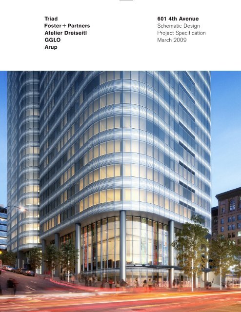
Triad<br />
Atelier Dreiseitl<br />
GGLO<br />
Arup<br />
<strong>601</strong> <strong>4th</strong> <strong>Avenue</strong><br />
<strong>Schematic</strong> <strong>Design</strong><br />
<strong>Project</strong> <strong>Specification</strong><br />
<strong>March</strong> <strong>2009</strong>
<strong>601</strong> Fourth <strong>Avenue</strong> OUTLINE SPECIFICATION<br />
Seattle, Washington<br />
000001 - TABLE OF CONTENTS<br />
Page 1 of 3<br />
Section<br />
Division 00<br />
Title<br />
Introductory Information<br />
000100 Building Walkthrough<br />
Architectural Acoustics and Mechanical Noise Control Recommendations - Refer to<br />
Acoustic Consultant’s Documents<br />
Division 01<br />
General Requirements<br />
010000 General Requirements<br />
011101 Technical Reference Sheet – Exterior Wall Systems, Interior Wall Systems and /Canopies<br />
014540 Testing of Curtain Wall Systems<br />
Division 02<br />
Existing Conditions<br />
Structure Demolition: Refer to Structural Engineer’s Documents<br />
Division 03<br />
Concrete<br />
Cast-in-Place Concrete: Refer to Structural Engineer’s Documents<br />
033500 Architectural Concrete Finishes<br />
Division 04<br />
Masonry<br />
042200 Concrete Unit Masonry<br />
044300 Stone Exterior Cladding<br />
Division 05<br />
Metals<br />
Structural Steel Framing and Decking – Refer to Structural Engineer’s Documents<br />
051213 Architecturally Exposed Structural Steel Framing<br />
054100 Cold-Formed Metal Framing<br />
055000 Metal Fabrications<br />
055100 Metal Stairs<br />
057500 Decorative Formed Metal<br />
Division 06<br />
Wood, Plastics and Composites<br />
061000 Rough Carpentry<br />
061624 Shock-Absorbing Subflooring<br />
062000 Finish Carpentry<br />
064023 Interior Architectural Woodwork<br />
Division 07<br />
Thermal and Moisture Protection<br />
071326 Self-Adhering Sheet Waterproofing<br />
071413 Hot Fluid-Applied Rubberized Asphalt Waterproofing<br />
071800 Traffic Coatings<br />
072100 Thermal Insulation<br />
072712 Air Barriers/Vapor Retarders<br />
075200 Modified Bituminous Membrane Roofing<br />
075556 Fluid-Applied Protected Membrane Roofing<br />
076200 Sheet Metal Flashings and Trim<br />
078415 Firestopping and Fire-Resistive Joint Systems<br />
079200 Joint Sealants<br />
079500 Expansion Control<br />
19 December, 2008 Foster+ Partners
<strong>601</strong> Fourth <strong>Avenue</strong> OUTLINE SPECIFICATION<br />
Seattle, Washington<br />
000001 - TABLE OF CONTENTS<br />
Page 2 of 3<br />
Division 08<br />
Openings<br />
081113 Hollow Metal Doors and Frames<br />
081410 Wood Doors and Frames<br />
083113 Access Doors and Frames<br />
083326 Overhead Coiling Grilles<br />
083513 Folding Sliding Doors – Storefronts<br />
084113 Aluminum-Framed Entrances and Screens<br />
084126 All-Glass Doors and Screens<br />
084127 Fire Rated All-Glass Screens<br />
084223 Revolving Door Entrances<br />
084224 Circular Bi-Parting Entrance Doors<br />
084413 Glazed Aluminum Curtain Walls<br />
087100 Door Hardware<br />
088000 Glazing<br />
080001 Curtain Wall Glazing – Quality Control<br />
089000 Metal Wall Louvers<br />
Division 09<br />
Finishes<br />
092116 Gypsum Board Assemblies<br />
092216 Non-Load-Bearing Metal Framing<br />
093000 Tiling<br />
095123 Acoustical Fiber Panel Ceilings<br />
095133 Acoustical Metal Panel Ceilings<br />
096340 Stone Flooring<br />
096400 Wood Flooring<br />
096500 Resilient Flooring<br />
096816 Sheet Carpeting<br />
096900 Access Flooring<br />
097213 Glass Fiber Gypsum Fabrications<br />
097505 Interior Stone Furniture<br />
097723 Fabric-Wrapped Wall Panels<br />
099100 Painting<br />
099600 Resinous Coatings<br />
Division 10 Specialties<br />
101400 Signage<br />
102113 Toilet Compartments<br />
102213 Wire Mesh Partitions<br />
102610 Wall Protection<br />
102800 Toilet Accessories<br />
104413 Fire Extinguisher and Hose Cabinets<br />
105113 Metal Lockers<br />
105523 Mail Boxes<br />
Division 11 Equipment<br />
Building Facade Maintenance Equipment: Refer to Maintenance Consultant’s Documents<br />
111200 Parking Control Equipment<br />
111300 Loading Dock Equipment<br />
118200 Solid Waste Handling Equipment<br />
Division 12 Furnishings<br />
124816 Entrance Floor Grilles<br />
129300 Site Furnishings<br />
19 December, 2008 Foster+ Partners
<strong>601</strong> Fourth <strong>Avenue</strong> OUTLINE SPECIFICATION<br />
Seattle, Washington<br />
000001 - TABLE OF CONTENTS<br />
Page 3 of 3<br />
Division 13 Special Construction<br />
Security Systems: Refer to Electrical Engineer’s Documents<br />
Division 14 Conveying Equipment<br />
Elevators: Refer to Conveying System Consultant’s Documents<br />
142115 Elevator Car Finishing<br />
143110 Escalators – Architectural Requirements<br />
149182 Trash Chutes<br />
Divisions 22 Plumbing<br />
Refer to Mechanical Consultant’s Documents<br />
224001 Plumbing Fixtures – Architectural Requirements<br />
Division 23 Heating, Ventilating and Air Conditioning<br />
Refer to Mechanical Consultant’s Documents<br />
Division 26 Electrical<br />
Refer to Electrical Consultant’s Documents<br />
Refer to Lighting Consultant’s Documents for Interior Lighting Fixtures<br />
Division 31 Site Clearing<br />
Site Clearing, Earthwork, Caissons, Excavation Support Systems: Refer to Civil Engineer’s<br />
Documents<br />
Division 32 Exterior Improvements<br />
Bituminous Concrete Pavement, Portland Cement Concrete Pavement: Refer to Civil<br />
Engineer’s Documents<br />
Unit Paving,Stone Paving, Stone Landscaping Walls, Exterior Balustrades to Plaza, Tree<br />
Gratings, Trees, Shrubs, Plants and Irrigation: Refer to Landscape Architect’s Documents<br />
END OF DOCUMENT<br />
19 December, 2008 Foster+ Partners
<strong>601</strong> Fourth <strong>Avenue</strong> OUTLINE SPECIFICATION<br />
Seattle, Washington<br />
000100 – BUILDING WALKTHROUGH<br />
Page 1 of 10<br />
PART 1 - GENERAL<br />
1.1 PARKING<br />
A. Concrete floors with traffic coating finish.<br />
B. Exposed concrete walls.<br />
C. Sealed exposed concrete unit masonry walls.<br />
D. Painted pavement markings.<br />
E. Concrete columns.<br />
F. Automatic metal doors.<br />
G. Steel stair with cast-in-place concrete treads.<br />
H. Exposed services.<br />
I. Architectural lighting.<br />
J. Sprinklers throughout.<br />
K. Custom and statutory signage.<br />
1.2 METRO ENTRY<br />
A. Natural stone flooring.<br />
B. Exterior natural stone cladding panels.<br />
C. Architectural lighting to Lighting Consultant’s specification.<br />
D. Custom signage.<br />
E. Custom uprising security gates.<br />
1.3 METRO EGRESS STAIRS<br />
A. Steel stair with cast-in-place concrete treads.<br />
B. Metal balustrade with stainless steel tubular handrail.<br />
C. Steelwork welded connections ground smooth.<br />
D. Lighting to Lighting Consultant’s specification.<br />
1.4 METRO ELEVATOR<br />
A. Stone flooring to elevator car interior to match lobby.<br />
B. Stainless steel elevator doors and door moldings.<br />
C. Stainless steel and mirror panels to elevator car interior.<br />
D. Illuminated signage and control panel.<br />
19 December, 2008 Foster + Partners
<strong>601</strong> Fourth <strong>Avenue</strong> OUTLINE SPECIFICATION<br />
Seattle, Washington<br />
000100 – BUILDING WALKTHROUGH<br />
Page 2 of 10<br />
E. Stainless steel panel ceiling with concealed support system and integrated feature lighting.<br />
1.5 METRO ESCALATORS<br />
A. Exterior use.<br />
B. Stainless steel cladding.<br />
C. Glass balustrades.<br />
D. Integrated handrail lighting.<br />
1.6 MECHANICAL ROOMS<br />
A. Resilient Flooring.<br />
B. Custom and statutory signage.<br />
C. Metal doors.<br />
D. Stainless steel door hardware: Allgood D-Line or equivalent.<br />
1.7 BICYCLE STORAGE AND SHOWER ROOMS<br />
A. Bicycle racks.<br />
B. Lockers.<br />
C. Concrete floors with pedestrian coating finish.<br />
D. Porcelain flooring to toilet and shower rooms.<br />
E. Porcelain walls to toilet and shower rooms.<br />
F. Painted gypsum board ceilings with concealed support system anchored to steel structure.<br />
G. Architectural lighting.<br />
H. Plastic laminate toilet partitions.<br />
I. Wall hung lavatory basins.<br />
J. Wall hung washroom fixtures.<br />
K. High quality accessories, including:<br />
.1 Frameless mirrors over lavatory basins.<br />
.2 Sensor toilet flushes and taps.<br />
.3 Integrated paper towel and soap dispensers.<br />
1.8 RETAIL FEATURE STAIR<br />
A. Feature staircase formed in architectural metalwork with stone treads.<br />
B. Glass balustrade.<br />
C. Handrail: Formed tubular stainless steel.<br />
1.9 RETAIL TENANT SPACES<br />
A. Exposed concrete floor finish.<br />
19 December, 2008 Foster + Partners
<strong>601</strong> Fourth <strong>Avenue</strong> OUTLINE SPECIFICATION<br />
Seattle, Washington<br />
000100 – BUILDING WALKTHROUGH<br />
Page 3 of 10<br />
B. Full-height aluminum framed glazing with folding-sliding and hinged/pivoted doors.<br />
C. Exposed concrete core walls.<br />
D. Onyx panel cladding to core walls of tower.<br />
E. Exposed concrete soffits.<br />
1.10 OFFICE RECEPTION, PUBLIC LOBBY, AND RESIDENTIAL LOBBY<br />
A. Natural stone flooring.<br />
B. 6 inch high stone wall base with ½-inch shadow gap flush to wall cladding.<br />
C. Full-height aluminum framed glazing.<br />
D. Glazed revolving door and hinged/pivoted doors.<br />
E. Back-lit onyx panel cladding to core walls.<br />
F. Glass balustrades<br />
G. Full-height fire-rated glass screens<br />
H. Metal clad internal columns.<br />
I. Custom reception desks.<br />
J. Metal panel ceiling with integrated feature lighting.<br />
K. Stainless steel door hardware: Allgood D-Line or equivalent.<br />
L. Custom and statutory signage.<br />
M. Mailboxes.<br />
1.11 PUBLIC RESTROOMS<br />
A. Natural stone flooring.<br />
B. 6 inch high stone wall base with ½-inch shadow gap flush to wall cladding.<br />
C. Back painted glass panel walls with stone wall base.<br />
D. Gypsum board ceiling with plaster skimcoat and painted finish.<br />
E. Wood veneer panel, cubicle, and vanity system.<br />
F. Wood doors.<br />
G. Stainless steel door hardware: Allgood D-line or equivalent<br />
H. White porcelain plumbing fixtures.<br />
1.12 OFFICE ELEVATOR LOBBIES<br />
A. Natural stone flooring.<br />
B. 6 inch high stone wall base with ½-inch shadow gap flush to wall cladding.<br />
C. Back-lit Onyx panel wall cladding.<br />
19 December, 2008 Foster + Partners
<strong>601</strong> Fourth <strong>Avenue</strong> OUTLINE SPECIFICATION<br />
Seattle, Washington<br />
000100 – BUILDING WALKTHROUGH<br />
Page 4 of 10<br />
D. Metal panel ceilings.<br />
E. Bespoke elevator call buttons and indicator lights<br />
F. Architectural lighting.<br />
1.13 OFFICE ELEVATORS<br />
A. Stone flooring to elevator car to match lobby.<br />
B. Stainless steel elevator doors and door moldings.<br />
C. Stainless steel and mirror panels to elevator car interior.<br />
D. Illuminated signage and control panel.<br />
E. Stainless steel panel ceilings with integrated feature lighting.<br />
1.14 PARKING SHUTTLE ELEVATORS<br />
A. Stone flooring to elevator car to match lobby.<br />
B. Stainless steel elevator doors and door moldings.<br />
C. Stainless steel and mirror panels to elevator car interior.<br />
D. Illuminated signage and control panel.<br />
E. Stainless steel panel ceilings with integrated feature lighting.<br />
1.15 SERVICE ELEVATORS<br />
A. Rubber/checker plate flooring.<br />
B. Stainless steel elevator doors and door moldings.<br />
C. Stainless steel panels to elevator car interior.<br />
D. Illuminated signage and control panel.<br />
E. High-set stainless steel panel ceiling with integrated lighting.<br />
1.16 ESCAPE STAIRS<br />
A. Steel stair with cast-in-place concrete treads.<br />
B. Metal balustrade with tubular handrail.<br />
C. Steelwork welded connections ground smooth.<br />
D. Lighting to Lighting Consultant’s specification.<br />
1.17 OFFICE FLOOR ELEVATOR LOBBIES<br />
A. Taped gypsum board ceiling.<br />
B. Architectural cove lighting.<br />
C. Stainless steel door hardware: Allgood D-Line or equivalent.<br />
19 December, 2008 Foster + Partners
<strong>601</strong> Fourth <strong>Avenue</strong> OUTLINE SPECIFICATION<br />
Seattle, Washington<br />
000100 – BUILDING WALKTHROUGH<br />
Page 5 of 10<br />
D. Metal doors to cores.<br />
E. Sprinklers throughout.<br />
1.18 OFFICE AREA TENANT SPACES<br />
A. Exposed concrete floor finish.<br />
B. Exposed concrete core walls.<br />
C. Sprinklers throughout.<br />
D. Metal doors to cores and mechanical and electrical rooms.<br />
E. Stainless steel door hardware: Allgood D-Line or equivalent.<br />
1.19 OFFICE RESTROOMS<br />
A. Porcelain tile flooring.<br />
B. Porcelain tile to walls.<br />
C. Painted gypsum board ceilings with concealed support system anchored to steel structure.<br />
D. Architectural lighting.<br />
E. Plastic laminate toilet partitions.<br />
F. Wall hung lavatory basins.<br />
G. Wall hung washroom fixtures.<br />
H. High quality accessories, including:<br />
.1 Frameless mirrors over lavatory basins.<br />
.2 Sensor toilet flushes and taps.<br />
.3 Integrated paper towel and soap dispensers.<br />
1.20 RESIDENTIAL ELEVATOR LOBBIES<br />
A. Natural stone flooring.<br />
B. 6 inch high stone wall base with ½-inch shadow gap flush to wall cladding.<br />
C. Back-lit onyx panel wall cladding.<br />
D. Metal panel ceilings with concealed support system anchored to steel structure.<br />
E. Architectural lighting.<br />
F. Stainless steel elevator doors and door moldings.<br />
G. Sprinklers throughout.<br />
H. Custom and statutory signage.<br />
I. Metal clad doors to core.<br />
J. All-glass doors to corridors.<br />
K. Stainless steel door hardware: Allgood D-Line or equivalent.<br />
19 December, 2008 Foster + Partners
<strong>601</strong> Fourth <strong>Avenue</strong> OUTLINE SPECIFICATION<br />
Seattle, Washington<br />
000100 – BUILDING WALKTHROUGH<br />
Page 6 of 10<br />
1.21 RESIDENTIAL CORRIDORS<br />
A. Carpet flooring.<br />
B. 6 inch high wood baseboard to match door finish.<br />
C. Gypsum board partitions with fabric wall covering.<br />
D. Painted gypsum board ceilings with concealed support system anchored to steel structure.<br />
E. Architectural lighting.<br />
F. Fire rated flush wood doors to residential unit entry doors.<br />
1.22 RESIDENTIAL LIVING SPACES - LIVING ROOMS, BEDROOMS AND STUDIES<br />
A. Wood flooring to living and dining spaces.<br />
B. Carpet flooring to bedrooms and studies.<br />
C. 6 inch high wood baseboard to match door finish<br />
D. Painted gypsum board walls.<br />
E. Painted gypsum board ceilings.<br />
F. Sprinklers throughout.<br />
G. GFRP column casings with skim-coated, painted finish.<br />
H. Architectural lighting.<br />
I. Wood doors.<br />
J. Operable panels separating bedrooms from living rooms.<br />
K. Stainless steel door hardware Allgood D-Line or equivalent.<br />
L. Glazed sliding doors.<br />
1.23 RESIDENTIAL BATHROOMS<br />
A. Porcelain tile flooring.<br />
B. Porcelain tile to walls.<br />
C. Glass backsplash.<br />
D. Mirror.<br />
E. Painted gypsum board ceilings with concealed support system anchored to steel structure.<br />
F. Recessed downlights.<br />
G. Undermount bathtub.<br />
H. Wall mount lavatory basins.<br />
I. Wall hung toilet with concealed cistern and support frame.<br />
J. Chrome taps, shower and flush plate.<br />
19 December, 2008 Foster + Partners
<strong>601</strong> Fourth <strong>Avenue</strong> OUTLINE SPECIFICATION<br />
Seattle, Washington<br />
000100 – BUILDING WALKTHROUGH<br />
Page 7 of 10<br />
K. Chrome toilet accessories including toilet tissue holder, towel bars and robe hooks.<br />
L. Chrome shower heads including wall and ceiling mounted type.<br />
M. Low-iron extra-clear frameless glass shower partition.<br />
N. Wood doors.<br />
O. Stainless steel door hardware: Allgood D-Line or equivalent.<br />
1.24 RESIDENTIAL UTILITY CLOSETS<br />
A. Resilient floor finish.<br />
B. Painted gypsum board walls.<br />
C. Painted gypsum board ceilings.<br />
D. Wood doors.<br />
E. Stainless steel door hardware: Allgood D-Line or equivalent.<br />
1.25 RESIDENTIAL CASEWORK<br />
A. Laminate-faced custom coat closets, closets and walk-in closets.<br />
B. Drawers.<br />
C. Stainless steel coat rods.<br />
D. Integrated mirrors.<br />
E. Stainless steel door handles.<br />
1.26 RESIDENTIAL KITCHENS<br />
A. Polyester lacquered casework.<br />
B. Glass backsplash.<br />
C. Reconstituted stone countertops.<br />
1.27 RESIDENTIAL BALCONIES<br />
A. Porcelain tile floor finish.<br />
B. Glass balustrade with stainless steel handrail.<br />
C. Architectural lighting.<br />
D. Full-height glazed sliding doors.<br />
E. Stainless steel door hardware.<br />
1.28 AMENITY LEVEL ELEVATOR LOBBY<br />
A. Natural stone flooring.<br />
B. 6 inch high stone wall base with ½-inch shadow gap flush to wall cladding.<br />
19 December, 2008 Foster + Partners
<strong>601</strong> Fourth <strong>Avenue</strong> OUTLINE SPECIFICATION<br />
Seattle, Washington<br />
000100 – BUILDING WALKTHROUGH<br />
Page 8 of 10<br />
C. Back-lit onyx panel wall cladding.<br />
D. Metal panel ceilings with concealed support system anchored to steel structure.<br />
E. Architectural lighting.<br />
F. Stainless steel elevator doors and door moldings.<br />
G. Sprinklers throughout.<br />
H. Custom and statutory signage.<br />
I. Metal clad doors to core.<br />
J. All-glass doors to fitness and bar/lounge areas.<br />
K. Stainless steel door hardware: Allgood D-Line or equivalent.<br />
1.29 AMENITY LEVEL FITNESS AREA<br />
A. Carpet flooring with shock-absorbing subfloor on raised access floor.<br />
B. Painted gypsum board walls.<br />
C. Metal panel ceilings with integrated feature lighting.<br />
D. GFRP column casings with skim-coated and paint finish.<br />
E. Metal clad doors.<br />
F. Stainless steel door hardware: Allgood D-Line or equivalent.<br />
1.30 AMENITY LEVEL FITNESS AREA LOCKER ROOMS<br />
A. Porcelain tile flooring.<br />
B. 6 inch tile wall base with ½-inch shadow gap flush to wall cladding.<br />
C. Painted gypsum board walls.<br />
D. Wall hung lavatory basins.<br />
E. Wall mirrors.<br />
F. Painted gypsum board ceilings.<br />
G. GFRP column casings with skim-coated and paint finish.<br />
H. Architectural lighting.<br />
I. Laminate faced casework.<br />
J. Steel coat rods.<br />
K. Stainless steel door handles to casework.<br />
L. High quality accessories, including:<br />
.1 Frameless mirrors over lavatory basins.<br />
.2 Sensor toilet flushes and taps.<br />
.3 Integrated paper towel and soap dispensers.<br />
19 December, 2008 Foster + Partners
<strong>601</strong> Fourth <strong>Avenue</strong> OUTLINE SPECIFICATION<br />
Seattle, Washington<br />
000100 – BUILDING WALKTHROUGH<br />
Page 9 of 10<br />
M. Wood doors.<br />
N. Stainless steel door hardware: Allgood D-Line or equivalent.<br />
1.31 AMENITY LEVEL BAR / LOUNGE AREA AND MEDIA ROOM<br />
A. Natural stone flooring on raised access floor.<br />
B. 6 inch high stone wall base with ½-inch shadow gap flush to wall cladding.<br />
C. Full-height glazing.<br />
D. All-glass entrance doors.<br />
E. Back-lit onyx panel cladding to core walls.<br />
F. GRG column casings with skim-coated, painted finish.<br />
G. Custom reception desk.<br />
H. Metal panel ceilings with integrated feature lighting.<br />
I. Stainless steel door hardware: Allgood D-Line or equivalent.<br />
J. Custom and statutory signage.<br />
K. Custom fixed furnishings.<br />
1.32 AMENITY LEVEL RESTROOMS<br />
A. Natural stone flooring.<br />
B. 6 inch high stone wall base with ½-inch shadow gap flush to wall cladding.<br />
C. Back painted glass panel walls with stone wall base.<br />
D. Painted gypsum board ceilings with concealed support system anchored to steel structure.<br />
E. Architectural lighting.<br />
F. Plastic laminate toilet partitions.<br />
G. Wall hung lavatory basins.<br />
H. Wall hung plumbing fixtures.<br />
I. High quality accessories, including:<br />
.1 Frameless mirrors over lavatory basins.<br />
.2 Sensor toilet flushes and taps.<br />
.3 Integrated paper towel and soap dispensers.<br />
1.33 AMENITY LEVEL LIVE-WORK UNITS<br />
A. As residential units, with raised access floors.<br />
PART 2 - PRODUCTS (Not Used)<br />
PART 3 - EXECUTION (Not Used)<br />
19 December, 2008 Foster + Partners
<strong>601</strong> Fourth <strong>Avenue</strong> OUTLINE SPECIFICATION<br />
Seattle, Washington<br />
000100 – BUILDING WALKTHROUGH<br />
Page 10 of 10<br />
END OF SECTION<br />
19 December, 2008 Foster + Partners
<strong>601</strong> Fourth <strong>Avenue</strong> OUTLINE SPECIFICATION<br />
Seattle, Washington<br />
010000 – GENERAL REQUIREMENTS<br />
Page 1 of 2<br />
SECTION 016000 PRODUCT REQUIREMENTS<br />
.1 DELETERIOUS AND HAZARDOUS MATERIALS<br />
A. Do not use the following materials in the Work unless it can be demonstrated, to the satisfaction<br />
of the Architect, that they are safe during manufacture, installation and use and that their<br />
suitability is assured.<br />
1. Asbestos or asbestos-containing products, as defined in applicable codes and<br />
regulations.<br />
2. Lead, where the metal or its corrosive products may be directly ingested, inhaled or<br />
absorbed. Applications of lead such as roofing, flashings, rainwater goods and copper<br />
alloy fittings containing lead which are specifically required are acceptable, until equal or<br />
better alternatives are available.<br />
3. Lead-based paints and primers.<br />
4. Urea formaldehyde foam or materials which may release formaldehyde beyond British<br />
Standard limits.<br />
5. Pitch polymer damp-proofing.<br />
6. Materials which generally comprise mineral fibres, either man-made or naturally occurring,<br />
which have a diameter of 3 microns or less and a length of 200 microns or less, or which<br />
contain fibres not sealed, encapsulated, or otherwise stabilised to ensure that fibre<br />
migration is prevented. Products that may contain these fibres include insulation, fire<br />
protection and air filters. For mineral wool insulation products, test evidence must be<br />
available and produced confirming that the materials fulfil the requirements of applicable<br />
codes and regulations, and are not classified as a possible human carcinogen.<br />
7. Chlorofluorocarbons or hydrochlorofluorocarbons or any goods and/or materials<br />
containing the same (e.g. materials in which CFCs, HCFCs or HFAs have been used as<br />
blowing agents).<br />
8. The use of a species of hardwood from the tropical rainforests is not permitted unless it<br />
is obtained from sustainable resources.<br />
9. High alumina cement in structural elements.<br />
10. Wood wool slabs in permanent formwork to concrete or in structural elements.<br />
11. Calcium chloride in admixtures for use in reinforced concrete.<br />
12. Aggregates for use in reinforced concrete which do not comply with BS EN 12620 and<br />
aggregates for use in concrete which do not comply with the provisions of BS 8110, or<br />
acceptable equivalent U.S. standards or codes.<br />
13. Polychlorinated biphenyls (PCBs), polychlorinated terphenyls (PCTs) or any goods<br />
and/or materials containing the same.<br />
14. Calcium silicate bricks or tiles.<br />
15. Sea dredged aggregates.<br />
16. Lindane - wood treatment/insecticidal spray.<br />
17. Pentachlorophenol (PCP) or timber treated with Pentachlorophenol - biocide/wood<br />
preservative.<br />
18. Chromated Copper Arsenate (CCA) timber preservative treatment.<br />
19. Tributyltin (TBT).<br />
20. When necessary to use the listed materials, prepare and submit detailed observations<br />
based upon the guidelines contained in the document Good Practice in the Selection of<br />
Construction Materials, prepared by Ove Arup & Partners.<br />
SECTION 017419 CONSTRUCTION WASTE MANAGEMENT AND DISPOSAL<br />
.1 Salvage, recycle and dispose of nonhazardous construction waste.<br />
19 December, 2008 Foster + Partners
<strong>601</strong> Fourth <strong>Avenue</strong> OUTLINE SPECIFICATION<br />
Seattle, Washington<br />
010000 – GENERAL REQUIREMENTS<br />
Page 2 of 2<br />
.2 Achieve end-of-<strong>Project</strong> rates for salvage/recycling as required by applicable LEED requirements for<br />
non-hazardous solid waste generated by the Work.<br />
.3 Practice efficient waste management in the use of materials in the course of the Work. Use all<br />
reasonable means to divert construction waste from landfills and incinerators. Facilitate recycling<br />
and salvage of materials.<br />
SECTION 018113 SUSTAINABLE DESIGN REQUIREMENTS<br />
.1 LEED: Leadership in Energy and Environmental <strong>Design</strong>.<br />
.2 Required Standard: The Work shall achieve a minimum Gold standard when assessed under the<br />
LEED-NC, Version 2.2 Green Building Rating System for New Construction and Major Renovations<br />
by the United States Green Building Council (USGBC).<br />
.3 Independent Assessment: The Work will be assessed by independent LEED-accredited<br />
Professional to assess and confirm the status of the sustainability requirements during the design<br />
and construction stages. The LEED Professional may also serve as waste management coordinator.<br />
.4 Submittals: Submit product data, cost information and progress reports to facilitate the certification<br />
process.<br />
END OF SECTION<br />
19 December, 2008 Foster + Partners
<strong>601</strong> Fourth <strong>Avenue</strong> OUTLINE SPECIFICATION<br />
Seattle, Washington<br />
011101 – Technical Reference Sheet<br />
Page 1 of 2<br />
PART 1 – GENERAL<br />
1.1 GENERAL<br />
.1 The following drawing description references identify systems/components/products<br />
referenced in the <strong>Specification</strong>s and on the Drawings.<br />
1.2 SCHEDULE OF REFERENCES<br />
REF Description Section<br />
Exterior Wall Systems / Internal Wall<br />
Systems / Canopies<br />
EWS-1a Double-height stick-framed shopfront<br />
084413<br />
system<br />
EWS-1b Stick-framed shopfront system 084413<br />
EWS-1c Inverted stick-framed shopfront system 084413<br />
EWS-1d Balcony cladding 084413<br />
EWS-1e Folding sliding doors for storefront 083513<br />
EWS-1f Folding sliding doors for storefront 083513<br />
EWS-1g Frameless glazing 084413<br />
EWS-2a Unitised curtainwall system 084413<br />
EWS-2b Unitised curtainwall system 084413<br />
EWS-2c Balcony cladding 084413<br />
EWS-3a Unitised curtainwall system 084413<br />
EWS-3b Balcony cladding 084413<br />
EWS-3c Unitised curtainwall system 084413<br />
EWS-4 Glass screen on exposed steel<br />
051213/084413<br />
structure<br />
EWS-5 Glass canopy on exposed steel<br />
051213/084413<br />
structure<br />
EWS-6a Unitised column cladding 057500/084413<br />
EWS-6b Column cladding 057500<br />
EWS-7 Soffit cladding 084413<br />
EWS-8 Metal wall louvers 089000<br />
EWS-9 Green wall 042200<br />
EWS-10 Exterior framed screen 084113<br />
IWS-1a Balcony cladding 055000/057500<br />
IWS-1b Fire-rated all-glass screen 084127<br />
CAN-1 Metal-clad steel canopy 051213/057500<br />
CAN-2 Exposed steel and glass canopy 051213/057500<br />
PART 2- PRODUCTS<br />
2.1 NOT USED<br />
.1 Not Used.<br />
4 June, 2008 Foster + Partners
<strong>601</strong> Fourth <strong>Avenue</strong> OUTLINE SPECIFICATION<br />
Seattle, Washington<br />
011101 – Technical Reference Sheet<br />
Page 2 of 2<br />
PART 3 - EXECUTION<br />
3.1 NOT USED<br />
.1 Not Used.<br />
END OF SECTION<br />
4 June, 2008 Foster + Partners
<strong>601</strong> Fourth <strong>Avenue</strong> OUTLINE SPECIFICATION<br />
Seattle, Washington<br />
014540 – TESTING OF<br />
CURTAIN WALL SYSTEMS<br />
Page 1 of 2<br />
PART 1 - GENERAL<br />
1.1 SECTION REQUIREMENTS<br />
A. Summary:<br />
.1 Requirements of testing services agency, engaged by Owner, to verify performance and<br />
compliance of curtain wall systems, prior to construction.<br />
.2 Services Required: Testing of laboratory mock-ups.<br />
B. Related Sections:<br />
.1 Section 084413 – Glazed Aluminum Curtain Walls.<br />
.2 Section 088001 – Curtain Wall Glazing – Quality Control.<br />
1.2 SUBMITTALS<br />
A. Provide Schedule of Tests and Inspections, and Test and Inspection Reports for each test.<br />
B. Submit As-Built Drawings of mock-ups indicating modifications or additions required to comply with<br />
the specified performance requirements.<br />
1.3 QUALITY ASSURANCE<br />
A. Testing Agency Qualifications: An NRTL, an NVLAP, or an independent agency with the experience<br />
and capability to conduct testing specified, according to ASTM E 699; and with additional qualifications<br />
required by authorities having jurisdiction, that is acceptable to authorities.<br />
.1 NRTL: A nationally recognized testing laboratory according to 29 CFR 1910.7.<br />
.2 NVLAP: A testing agency accredited according to NIST's National Voluntary Laboratory<br />
Accreditation Program.<br />
1.4 LABORATORY TESTS<br />
A. Testing laboratory to conduct and report outcome of tests, including compliance and noncompliance<br />
with applicable construction documents.<br />
B. Testing of curtain wall mockups to be performed in test laboratory chamber construction provided<br />
by Contractor, using procedures acceptable to Architect, prior to testing.<br />
C. Tests on mockups to be as specified and as selected by Architect, and in presence of Architect,<br />
Contractor and curtain wall manufacturer.<br />
D. Mockups will be used primarily for testing performance of wall systems. Architect may use mockups<br />
to verify material selections to demonstrate aesthetic effects, qualities of materials and execution; to<br />
review coordination, testing, or operation; to show interface between dissimilar materials; and to<br />
demonstrate compliance with specified installation tolerances. Mockups are not Samples. Unless<br />
otherwise indicated, approved mockups establish the standard by which the Work will be judged.<br />
E. Order of Tests and Procedures:<br />
.1 Preload curtain wall mock-up.<br />
.2 Air infiltration static method, including chamber calibration, to ASTM E 283.<br />
.3 Water penetration, static method, to ASTM E 331.<br />
.4 Water penetration, dynamic method, including engine calibration, to AAMA 501.1.<br />
.5 Uniform load deflection test to ASTM E 330, at design wind load and window washing<br />
equipment anchors at design conditions. For thermal break construction test to be performed<br />
19 December, 2008 Foster + Partners
<strong>601</strong> Fourth <strong>Avenue</strong> OUTLINE SPECIFICATION<br />
Seattle, Washington<br />
014540 – TESTING OF<br />
CURTAIN WALL SYSTEMS<br />
Page 2 of 2<br />
at exterior temperature of -10 deg F, and with an exterior metal surface temperature of 120<br />
deg F in addition to the ambient temperature in the test laboratory; at test laboratory's option<br />
this test may be performed as part of the Thermal Cycle test specified in paragraph 14.<br />
.6 Air infiltration, static method, including chamber calibration, to ASTM E 283.<br />
.7 Water penetration, static method, to ASTM E 331.<br />
.8 Water penetration, dynamic method, including engine calibration when engine has been<br />
moved from the position in the prior dynamic water infiltration test, to AAMA 501.1.<br />
.9 Interstory differential movement vertical and horizontal displacement test, at predicted building<br />
movement; six cycles. Test method to be acceptable to Architect, Structural Engineer and<br />
Curtain Wall Consultant; test to replicate project conditions anticipated on the building. Test<br />
specimen to be left with maximum open horizontal joint condition for further specified tests.<br />
.10 Air infiltration, static method, including chamber calibration, to ASTM E 283.<br />
.11 Water penetration, static method, to ASTM E 331.<br />
.12 Water penetration, dynamic method, including engine calibration when engine has been<br />
moved from the position in prior dynamic water infiltration test, to AAMA 501.1.<br />
.13 Condensation resistance to AAMA 1503. Test conditions for each test to be maintained for<br />
24 hours after equilibrium is attained.<br />
.14 Thermal cycle; six cycles.<br />
.15 Air infiltration, static method, including chamber calibration, to ASTM E 283.<br />
.16 Water penetration, static method, to ASTM E 331.<br />
.17 Water penetration, dynamic method, including engine calibration when engine has been<br />
moved from the position in prior dynamic water infiltration test, to AAMA 501.1.<br />
a. Perform supplemental test, as directed, to verify sufficiency of internal weep drainage<br />
network. Remove sealant at locations designated by Architect, and retest for static<br />
and dynamic water penetration.<br />
.18 Window washing window washing equipment anchors ultimate failure load resistance test.<br />
.19 Dynamic wind load structural test on mullions. Test method to be accepted by Contractor<br />
and Architect.<br />
.20 Structural test at 1.5 times positive and negative design loads, to ASTM E 330, modified.<br />
.21 Interstory differential movement vertical and horizontal displacement test, at predicted building<br />
movement due to seismic event, when greater than due to wind; six cycles. Test method<br />
to be acceptable Architect, Structural Engineer and Curtain Wall Consultant; test to replicate<br />
project conditions anticipated on the building.<br />
.22 On structural silicone sealants used to provide structural bond between materials, apply 30<br />
lbf/sq. ft negative load. While under load inspect for loss of adhesion.<br />
.23 Operable window performance testing [Insert tests and coordinate location in test list].<br />
.24 Louvers testing [Insert tests and coordinate location in test list].<br />
PART 2 - PRODUCTS (Not Used)<br />
PART 3 - EXECUTION (Not Used)<br />
END OF SECTION<br />
19 December, 2008 Foster + Partners
<strong>601</strong> Fourth <strong>Avenue</strong> OUTLINE SPECIFICATION<br />
Seattle, Washington<br />
033500 – ARCHITECTURAL CONCRETE FINISHES<br />
Page 1 of 2<br />
PART 1 - GENERAL<br />
1.1 SECTION REQUIREMENTS<br />
A. Summary:<br />
.1 Finishes for formed concrete surfaces indicated to be left exposed in Office and Retail tenant<br />
spaces.<br />
B. Related Sections:<br />
.1 Section 099100 – Painting; coatings on concrete walls.<br />
.2 Structural Engineer’s specifications.<br />
1.2 SUBMITTALS<br />
A. Product Data: For coatings, repair materials, and accessories.<br />
1.3 QUALITY ASSURANCE<br />
A. Pre Fabrication Mock-up:<br />
.1 Mock up representative sample of finished concrete elements in field using specified<br />
materials for review of appearance and workmanship.<br />
B. Field Quality Control Benchmark: First of each type of cast-in-place concrete element to be<br />
finished.<br />
PART 2 - PRODUCTS<br />
2.1 MATERIALS<br />
A. Formwork for Architectural Concrete:<br />
.1 Use MDO plywood, rigid and sufficiently strong to withstand intended loads without<br />
deflection, movement or leakage, high hydraulic pressures from rapid filling and heavy<br />
frequency vibration.<br />
.2 Plug, tape, and seal cracks, holes, slits and gaps in forms to withstand pressure and remain<br />
completely watertight, and without affect specified appearance requirements.<br />
.3 Provide reveals as detailed.<br />
B. Formwork Accessories:<br />
.1 Fasteners for Formwork Bands, Reveals: Galvanized or other accepted non-corrosive steel<br />
materials.<br />
.2 Form Release Agent: Chemical non-staining release agent which will not change the<br />
appearance of the finished surface. Use release agents in strict accordance with the<br />
manufacturer's recommendations.<br />
C. Concrete Materials and Mixtures:<br />
.1 Use same brands and source for cement, aggregate and other constituents for the work.<br />
.2 Provide uniformity of colouration and other mix characteristics. Refer to Structural Engineer’s<br />
specifications.<br />
.3 Fine-Graded Granular Material: Clean mixture of crushed white marble or crushed stone as<br />
required, and manufactured or natural sand; ASTM D 448, Size 10, with 100 percent<br />
19 December, 2008 Foster + Partners
<strong>601</strong> Fourth <strong>Avenue</strong> OUTLINE SPECIFICATION<br />
Seattle, Washington<br />
033500 – ARCHITECTURAL CONCRETE FINISHES<br />
Page 2 of 2<br />
passing a No. 4 (4.75-mm) sieve and 10 to 30 percent passing a No. 100 (0.15-mm) sieve;<br />
complying with deleterious substance limits of ASTM C 33 for fine aggregates.<br />
.4 Comply with ACI 301 requirements for concrete mixtures. Refer to Structural Engineer’s<br />
specifications.<br />
.5 Ready-Mixed Concrete: Comply with ASTM C 94.<br />
D. Coatings for Exposed Concrete: Refer to Section 099100 - Painting.<br />
E. Repair Mortar: Specially formulated to matching concrete color, non-shrink, 5,000 psi compressive<br />
strength at 28 days.<br />
PART 3 - EXECUTION<br />
3.1 PREPARATION<br />
A. Refer to Structural Engineer’s specifications.<br />
3.2 CONCRETE PLACING AND CONSOLIDATION<br />
A. Refer to Structural Engineer’s specifications.<br />
3.3 STRIPPING, PROTECTION, CURING, CLEANING AND SEALING<br />
A. Form Removal: Refer to Structural Engineer’s specifications.<br />
B. Protection: Protect architectural concrete and reinforcement from damage and defacement during<br />
construction.<br />
C. Curing: Refer to Structural Engineer’s specifications.<br />
D. Cleaning: Clean surfaces and maintain free of foreign materials.<br />
3.4 APPEARANCE OF FORMED SURFACES<br />
A. Concrete surfaces shall appear thoroughly compacted. Surfaces shall be true, with clean arrises.<br />
Only very minor surface blemishes shall occur. No staining or discolouration from release agents is<br />
permitted.<br />
3.5 REPAIRS<br />
A. Areas of formed surfaces to be repaired shall be determined by the Architect, and shall not exceed<br />
specified extents.<br />
B. Before commencing repairs, confirm repair procedures and mix formulas with the Architect.<br />
C. Grind projections greater than 1/16 inch flush leave surface with uniform, smooth seamless<br />
appearance.<br />
D. Grind off irregularities of planeness on concealed faces.<br />
E. Fill voids larger than 1/8 inch flush with repair mortar; finished appearance to match adjacent<br />
surface.<br />
F. Fill tie holes.<br />
END OF SECTION<br />
19 December, 2008 Foster + Partners
<strong>601</strong> Fourth <strong>Avenue</strong> OUTLINE SPECIFICATION<br />
Seattle, Washington<br />
042200 – CONCRETE UNIT MASONRY<br />
Page 1 of 3<br />
PART 1 - GENERAL<br />
1.1 SECTION REQUIREMENTS<br />
A. Summary:<br />
.1 Interior and exterior concrete unit masonry, including mortar and grout, masonry<br />
reinforcement, anchors and accessories.<br />
B. Drawing Description References: The following reference codes and accompanying descriptions<br />
are contained in the Technical Reference Sheet (TRS) and identify systems/components/products<br />
indicated on the Drawings.<br />
.1 EWS-09: Green wall.<br />
C. Related Sections:<br />
1. Section 072712 - Air Barrier / Vapor Retarder Flashings for thru-wall flashings.<br />
2. Section 078413 – Firestopping and Fire-Resistive Joint Systems, for treatment of joints and<br />
penetrations in fire-rated partitions.<br />
3. Acoustic Consultant’s documents.<br />
1.2 DESIGN AND PERFORMANCE REQUIREMENTS<br />
A. <strong>Design</strong> exterior concrete unit masonry indicated as a Green Wall to be capable of receiving a<br />
plastic backing wall assembly for plants, irrigation system, and drainage without detriment to the<br />
wall’s performance. Provide necessary anchors and seals as applicable.<br />
B. Restraining steel sections required at tops of walls to be concealed.<br />
1.3 SUBMITTALS<br />
A. Product Data: For masonry units, mortar and grout additives, accessories. Include certificate of UL<br />
listing for rated materials.<br />
B. Manufacturer's Certificates: For masonry units, reinforcement and accessories indicating materials<br />
meet or exceed specified requirements.<br />
C. Mix <strong>Design</strong>s.<br />
D. Samples.<br />
1.4 QUALITY ASSURANCE<br />
A. Comply with ACI 530.1/ASCE 6/TMS 602.<br />
B. Regulatory Requirements: Comply with the requirements of applicable building codes.<br />
C. Mock-up: For each type of masonry wall construction.<br />
D. Field Quality Control Benchmark: First structural bay of each type of concrete unit masonry.<br />
19 December, 2008 Foster + Partners
<strong>601</strong> Fourth <strong>Avenue</strong> OUTLINE SPECIFICATION<br />
Seattle, Washington<br />
042200 – CONCRETE UNIT MASONRY<br />
Page 2 of 3<br />
PART 2 - PRODUCTS<br />
2.1 CONCRETE MASONRY UNITS<br />
A. Hollow Core Units: ASTM C 90; density and minimum compressive strength to suit exposure. Units<br />
for exterior walls manufactured with integral water repellent. Use non-fire rated units for fire rated<br />
assemblies when permitted by applicable Codes.<br />
B. Nominal face dimensions, 8 inch x 16 inch x depth indicated. Provide special shapes, including<br />
corner units and bond beams, for locations indicated.<br />
C. Furnish fine textured units for locations indicated to be left exposed or to receive paint finish.<br />
D. Fire-rated units to attain ratings where indicated. Block construction to provide rated partitions as<br />
indicated.<br />
E. Acoustically Rated Units: To achieve ratings specified in Acoustic Consultant’s documents.<br />
2.2 MORTAR AND GROUT<br />
A. Mortar: ASTM C 270-06, Type S. Masonry cement, plastic cement or calcium chloride in mortar<br />
not permitted.<br />
B. Grout: ASTM C 476, 1500 psi compressive strength minimum unless otherwise indicated on<br />
Structural Drawings. Slump of 8 to 11 inches.<br />
C. Admixtures: Types acceptable to Architect.<br />
D. Water: Potable.<br />
2.3 ACCESSORIES<br />
A. Steel Reinforcing Bars: ASTM A 615, Grade 60. Types as indicated on the Structural Drawings.<br />
B. Joint Reinforcement: ASTM A 951.<br />
.1 Coating: Mill galvanized.<br />
.2 Wire Diameter for Side Rods: W2.8 or 0.188-inch.<br />
.3 Wire Diameter for Cross Rods: W2.8 or 0.188-inch.<br />
.4 For single-wythe masonry, provide either ladder design or truss design.<br />
C. Thru-Wall Flashings: Flexible membrane flashings to Section 072712 Air Barrier / Vapor Retarder<br />
Flashings.<br />
D. Compressible Filler: Premolded strips to ASTM D 1056, Grade 2A1.<br />
PART 3 - EXECUTION<br />
3.1 PREPARATION<br />
A. Provide temporary bracing during erection of masonry work. Maintain in place until building<br />
structure provides permanent bracing.<br />
3.2 MORTAR AND GROUT<br />
A. Mortar and Grout Mixing: To specified reference standards.<br />
B. Admixtures: Add to manufacturer's instructions.<br />
19 December, 2008 Foster + Partners
<strong>601</strong> Fourth <strong>Avenue</strong> OUTLINE SPECIFICATION<br />
Seattle, Washington<br />
042200 – CONCRETE UNIT MASONRY<br />
Page 3 of 3<br />
C. Anti-freeze Compounds: Not permitted.<br />
3.3 INSTALLATION – GENERAL<br />
A. Coursing: Running bond.<br />
B. Fill cores in hollow concrete masonry units with grout 24 inches under bearing plates, beams,<br />
lintels, posts, and similar items, unless otherwise indicated.<br />
C. Build non-load-bearing interior partitions full height and install compressible filler in joint between<br />
top of partition and underside of structure above.<br />
D. Fire Rated Partitions: Treat joints, junctions with adjacent construction and penetrations in fire rated<br />
partitions to Section 078413 – Firestopping and Fire-Resistive Joint Systems.<br />
E. Tool joints flush in concealed masonry. Tool joints in exposed masonry slightly concave.<br />
F. Control Joints:<br />
.1 Provide control joints at not more than 25 feet to 32 feet to suit length of wall and at junction<br />
of masonry or concrete for horizontal expansion.<br />
.2 Seal control joints with polyurethane sealant.<br />
G. Built-in Work:<br />
.1 As work progresses, build-in hollow metal frames, window frames, steel lintels, shelf angles,<br />
nailing strips, anchor bolts, plates, and other similar items furnished by other Sections.<br />
.2 Bed anchors of hollow metal frames in mortar joints. Fill frame voids solid with mortar. Fill<br />
masonry cores with grout minimum 12 inches from framed openings.<br />
3.4 ANCHORAGE AND REINFORCING<br />
A. Provide reinforcement in cores as indicated, and as specified on the Structural Engineer’s<br />
Drawings.<br />
3.5 TOLERANCES<br />
A. To ACI 530.1/ ASCE 6/ TMS 602.<br />
END OF SECTION<br />
19 December, 2008 Foster + Partners
<strong>601</strong> Fourth <strong>Avenue</strong> DESIGN DEVELOPMENT SPECIFICATION<br />
Seattle, Washington<br />
044300 – STONE EXTERIOR CLADDING<br />
Page 1 of 3<br />
PART 1 - GENERAL<br />
1.1 SECTION REQUIREMENTS<br />
A. Summary:<br />
.1 Quarried cut stone in exterior wall cladding.<br />
.2 Associated flashings and supports<br />
B. Related Sections:<br />
.1 Section 055000 – Metal Fabrications.<br />
1.2 DESIGN REQUIREMENTS<br />
A. <strong>Design</strong> and engineer stone cladding to be gravity supported on steel supports anchored to concrete<br />
building structure or to secondary steel structure, to transmit the loads.<br />
B. <strong>Design</strong> steel support structure to applicable requirements of Section 05500 Metal Fabrications.<br />
C. <strong>Design</strong> stone cladding assembly to direct water collecting behind the stone to the outside.<br />
D. Mortar Joints: Open with back part of joint filled with mortar.<br />
E. Pattern Arrangement: Panels to be arranged with veining and other natural markings acceptable to<br />
Architect.<br />
1.3 SUBMITTALS<br />
A. Product Data, Shop Drawings and Samples:<br />
.1 Data on stone units including chemical analysis.<br />
.2 Range samples to indicate quality of color matching.<br />
.3 Samples for stone and framing.<br />
.4 Shop Drawings to include setting drawings.<br />
.5 Material test reports.<br />
1.4 QUALITY ASSURANCE<br />
A. Perform work to National Building Granite Quarries Association's document <strong>Specification</strong>s for Architectural<br />
Granite.<br />
B. Fabricator and Installer: Company specializing in performing the specified work with minimum 5<br />
years successful experience.<br />
C. Execute work by skilled mechanics experienced with the kind and form of stone and installation<br />
method indicated.<br />
D. Initial Stone Selection:<br />
.1 To be selected from uncut stone at quarry by Architect in presence of stone supplier, to verify<br />
desired appearances. Supplier to verify sufficient quantities, inclusive of reserves for breakage.<br />
.2 Subsequent pieces to be selected from cut blocks following Architect’s verification at quarry.<br />
E. Field Mock-Up: Sample wall panel 10 linear ft by floor-to-floor height, for verification of appearance,<br />
material qualities and execution. Include associated trim and masonry accessories. Test sealants,<br />
sealant compatibility and adhesion on mock-up.<br />
19 December, 2008 Foster + Partners
<strong>601</strong> Fourth <strong>Avenue</strong> DESIGN DEVELOPMENT SPECIFICATION<br />
Seattle, Washington<br />
044300 – STONE EXTERIOR CLADDING<br />
Page 2 of 3<br />
F. Field Quality Control Benchmark: First installation of structural bay of each type of stone including<br />
trim.<br />
G. Source Quality Control: Single quarry source for each stone type. Single source for mortar, stone<br />
accessories, sealants, and associated materials.<br />
PART 2 - PRODUCTS<br />
2.1 STONE<br />
A. Stone: Natural, quarried, free of efflorescence per ASTM C 6750.<br />
B. Granite: To ASTM C 615.<br />
C. Stone Colors and Finishes on Exposed Faces and Ends: To match Architect’s samples.<br />
D. Face Dimensions: As indicated.<br />
E. Thickness: To suit application, unless otherwise indicated.<br />
2.2 MORTAR<br />
A. To ASTM C 270, Proportion <strong>Specification</strong>, Type applicable for setting and pointing and to suit type<br />
of selected stone. Pointing mortar color as selected by Architect.<br />
B. Admixtures: Type acceptable to Architect.<br />
2.3 AUXILIARY MATERIALS<br />
A. Stone Accessories: Setting buttons, setting shims, ties and reinforcement. Anchors to be of<br />
stainless steel. Wire tiebacks to be copper-, bronze-, or brass-alloy wire.<br />
B. Anchor Support Framing: Roll-formed steel channels, galvanized to ASTM A 653/A 653M, G90.<br />
C. Weep Holes: Round polyethylene tubing, purpose made.<br />
D. Stone Cleaners: As recommended by National Building Granite Quarries Association's document<br />
<strong>Specification</strong>s for Architectural Granite, as applicable.<br />
E. Concealed Flashings: Self-adhesive sheets: of SBS modified bitumen laminated to high-density<br />
polyethylene film, minimum 40 mils thick.<br />
F. Flashing lap adhesives, control joint fillers.<br />
G. Extruded-Polystyrene Board Insulation: Rigid, cellular, polystyrene thermal insulation to ASTM C<br />
578, Type IV, R-value of 5.6.<br />
H. Sealer: Hydrophobic water-based impregnating no-sheen sealer suitable for natural stone. Sealer<br />
shall protect the stone from staining during setting and grouting process and allow evaporation of<br />
water from setting materials.<br />
I. Sealant: Clear silicone type.<br />
2.4 STONE FABRICATION<br />
A. Cut stone to produce pieces of thickness, size, and shape indicated.<br />
1. Fabricate stone to comply with recommendations of National Building Granite Quarries Association's<br />
document <strong>Specification</strong>s for Architectural Granite, as applicable.<br />
19 December, 2008 Foster + Partners
<strong>601</strong> Fourth <strong>Avenue</strong> DESIGN DEVELOPMENT SPECIFICATION<br />
Seattle, Washington<br />
044300 – STONE EXTERIOR CLADDING<br />
Page 3 of 3<br />
2. Provide molded work as indicated. Produce moldings with machines; do not sculpt moldings.<br />
Miter moldings at corners, unless otherwise indicated.<br />
3. Cut stone to produce uniform joints.<br />
4. Slightly ease outside corners.<br />
5. Provide cut-outs for fixtures.<br />
6. Apply sealer.<br />
B. Pattern Arrangement: Fabricate and arrange panels with veining and other natural markings acceptable<br />
to Architect.<br />
PART 3 - EXECUTION<br />
3.1 INSTALLATION<br />
A. Install work in accordance with ACI 530.1/ 530.1R/ ASCE 6-05/ TMS 602-05, Building Code Requirements<br />
for Masonry Structures & <strong>Specification</strong>s for Masonry Structures and Related Commentaries.<br />
B. Install stone to recommendations of National Building Granite Quarries Association's document<br />
<strong>Specification</strong>s for Architectural Granite, as applicable.<br />
C. Erect facings plumb and true with uniform joint widths. Use temporary shims to maintain joint width.<br />
D. Add admixtures to manufacturer's instructions. Anti-freeze compounds not permitted.<br />
E. Jointing Pattern and Joint Width: To be selected by Architect.<br />
F. Apply thin bead of sealant at movement joints, around cut-outs and at junctions with adjacent materials,<br />
and as indicated.<br />
G. Clean stone facing as work progresses. Clean interior stone facing at least six days after completion<br />
of grouting.<br />
END OF SECTION<br />
19 December, 2008 Foster + Partners
<strong>601</strong> Fourth <strong>Avenue</strong> OUTLINE SPECIFICATION<br />
Seattle, Washington 051213 – ARCHITECTURALLY EXPOSED STRUCTURAL STEEL FRAMING<br />
Page 1 of 4<br />
PART 1 - GENERAL<br />
1.1 SECTION REQUIREMENTS<br />
A. Summary:<br />
.1 Architecturally exposed structural steel (AESS) framing for exterior canopies and glass<br />
screens at roof.<br />
B. Drawing Description References: The following reference codes and accompanying descriptions are<br />
contained in the Technical Reference Sheet (TRS) and identify systems/components/products<br />
indicated on the Drawings.<br />
.1 CAN-2: Exposed steel and glass canopy.<br />
.2 EWS-4: Glass screen on exposed steel structure.<br />
.3 EWS-5: Glass canopy on exposed steel structure.<br />
C. Related Sections:<br />
.1 Section 079200 – Joint Sealants.<br />
.2 Section 084413 - Glazed Aluminum Curtain Walls.<br />
.3 Section 088000 – Glazing.<br />
.4 Section 09910 – Painting.<br />
.5 Structural Consultant’s documents; for requirements structural steel applicable to AESS<br />
framing.<br />
.6 Maintenance Consultant’s Documents; for building facade maintenance equipment.<br />
1.2 DESIGN REQUIREMENTS<br />
A. <strong>Design</strong> canopies for connection to building curtain wall framing without increase in curtain wall<br />
mullion framing size.<br />
B. <strong>Design</strong> supports to canopies using profiles at indicated locations, and to prevent displacement due<br />
to applicable loads.<br />
C. Architecturally Exposed Structural Steel (AESS): <strong>Design</strong> appearance of exposed steel assemblies<br />
for rooftop facades and canopies to match appearance qualities of Architect’s close-up photos.<br />
1.3 SUBMITTALS:<br />
A. Shop Drawings:<br />
.1 Indicate details of fabrication and installation, including:<br />
.a Welding symbols, grinding finishes and profiles of welds, locations of field joints.<br />
.b Types, sizes and orientations of bolt heads.<br />
.c Exposed surfaces and edges and surface preparation being used.<br />
.d Special tolerances and erection requirements.<br />
.2 Shop Drawings for structural assemblies to be prepared, signed and sealed by a structural<br />
engineer licensed in the State of the <strong>Project</strong>. Indicate compliance with Building Code<br />
requirements and structural analysis data.<br />
B. Samples: For each type of material and finish.<br />
1. Two steel plates with long edges joined by a groove weld and with weld ground smooth.<br />
2. Steel plate with one end of a short length of round steel tube welded to plate with a<br />
continuous fillet weld and with weld ground smooth and blended.<br />
19 December, 2008 Foster + Partners
<strong>601</strong> Fourth <strong>Avenue</strong> OUTLINE SPECIFICATION<br />
Seattle, Washington 051213 – ARCHITECTURALLY EXPOSED STRUCTURAL STEEL FRAMING<br />
Page 2 of 4<br />
C. Test Reports: Certified test reports showing compliance with specified performance characteristics<br />
and physical properties.<br />
D. Certificates: Product certificates signed by manufacturer certifying materials comply with specified<br />
performance characteristics and criteria and physical requirements.<br />
1.4 QUALITY ASSURANCE<br />
A. Installer Qualifications: A qualified installer who participates in the AISC Quality Certification<br />
Program and is designated an AISC-Certified Erector, Category CSE.<br />
B. Fabricator Qualifications: A qualified fabricator that participates in the AISC Quality Certification<br />
Program and is designated an AISC-Certified Plant, Category STD.<br />
C. Mock-ups: Build mock-ups for canopies and screens to set quality standards for fabrication and<br />
installation.<br />
D. Field Quality Control Benchmark: First installed assembly of each item, as selected by Architect.<br />
E. Coordination:<br />
.1 Coordinate selection of shop finishing with topcoats to be applied over them. Comply with<br />
paint and coating manufacturers' recommendations to ensure that shop primers and topcoats<br />
are compatible with one another.<br />
.2 Coordinate selection of metals, bolts, connectors and anchors with Structural Consultant’s<br />
documents. In case of conflict, the more stringent requirements shall apply.<br />
PART 2 - PRODUCTS<br />
2.1 METALS<br />
A. Steel Plates, Shapes, and Bars: ASTM A 36.<br />
B. Stainless Steel Materials:<br />
.1 Plate: ASTM A 666, Type 316.<br />
.2 Bar Stock: ASTM A 276, Type 316.<br />
.3 Tubing: ASTM A 269, Type 316, seamless welded.<br />
C. Rolled Steel Floor Plate: ASTM A 786/A 786M.<br />
D. Steel Tubing: Cold-formed steel tubing complying with ASTM A 500.<br />
E. Steel Pipe: ASTM A 53, standard weight (Schedule 40), black finish.<br />
2.2 GLASS<br />
A. Glass for Canopies and Screens: Refer to Section 088000 – Glazing.<br />
2.3 BOLTS, CONNECTORS AND ANCHORS<br />
A. General: Zinc plated fasteners to ASTM B 633, Class Fe/Zn 25 for electrodeposited zinc coating,<br />
for exterior use or where built into exterior walls. Select fasteners for the type, grade, and class<br />
required.<br />
B. Bolts and Nuts:<br />
.1 Regular hexagon-head bolts, ASTM A 307.<br />
19 December, 2008 Foster + Partners
<strong>601</strong> Fourth <strong>Avenue</strong> OUTLINE SPECIFICATION<br />
Seattle, Washington 051213 – ARCHITECTURALLY EXPOSED STRUCTURAL STEEL FRAMING<br />
Page 3 of 4<br />
.2 Stainless Steel Bolts, Hex Cap Screws, and Studs, ASTM F 593 and ASTM F 594, Type<br />
304.<br />
C. Expansion Anchors: Anchor bolt and sleeve assembly capable of sustaining, without failure, a load<br />
equal to 6 times the load imposed when installed in unit masonry and equal to 4 times the load<br />
imposed when installed in concrete per ASTM E 488.<br />
.1 Material: Carbon steel components zinc-plated to comply with ASTM B 633, Class Fe/Zn 5.<br />
.2 Material: Group 1 alloy 304 or 316 stainless-steel bolts and nuts complying with ASTM F<br />
593 and ASTM F 594.<br />
2.4 ACCESSORIES<br />
A. Sealants: Types to suit applications and as specified, and in accordance with Section 079200 –<br />
Joint Sealants.<br />
2.5 STEEL FINISHES<br />
A. Hot-dip galvanize exterior steel fabrications to ASTM A 123, unless otherwise specified. Galvanizing<br />
formula to suit application for field painting.<br />
B. Stainless Steel Finish: AISI No. 4, satin directional finish, unless otherwise specified.<br />
C. Field Paints: Refer to Section 09910 – Painting.<br />
2.6 FABRICATION – GENERAL<br />
A. Fabricate architecturally exposed steel assemblies to match quality and appearance of accepted<br />
mock-ups.<br />
B. Weld connections to greatest extent possible. Conceal bolted connections and anchors. Weld<br />
connections to AWS D1.1.<br />
2.7 EXTERIOR CANOPY TYPE CAN-2<br />
A. Fabricate from stainless steel structure to profiles and spacings indicated.<br />
B. Coordinate connections to curtain wall framing with Section 084413 - Glazed Aluminum Curtain<br />
Walls.<br />
2.8 EXTERIOR GLASS SCREENS AND EXTERIOR CANOPIES EWS-5<br />
A. Glass Screens:<br />
.1 Fabricate from galvanized structural steel sections to profiles and designs indicated to receive<br />
glass screen on aluminum carrier frames.<br />
.2 Make provisions for attachment of tracks, and associated items of building facade cleaning<br />
and maintenance equipment. Include reinforcement to support intended loads. Refer to<br />
Maintenance Consultant’s documents.<br />
B. Exterior Canopies:<br />
.1 Fabricate from flat and round galvanized steel profiles to receive glass screen cladding to<br />
comply with tolerances of finish material.<br />
.2 Coordinate connections to curtain wall framing with Section 084413 - Glazed Aluminum<br />
Curtain Walls.<br />
19 December, 2008 Foster + Partners
<strong>601</strong> Fourth <strong>Avenue</strong> OUTLINE SPECIFICATION<br />
Seattle, Washington 051213 – ARCHITECTURALLY EXPOSED STRUCTURAL STEEL FRAMING<br />
2.9 FINISHES:<br />
A. Galvanized Steel Assemblies: Shop galvanize steel and prepare ready for field painting.<br />
Page 4 of 4<br />
PART 3 - EXECUTION<br />
3.1 INSTALLATION<br />
A. Perform cutting, drilling, and fitting required for installing metal items. Set items accurately in<br />
location, alignment, and elevation; with edges and surfaces level, plumb, true, and free of rack.<br />
B. Touch up galvanizing of field welds.<br />
END OF SECTION<br />
19 December, 2008 Foster + Partners
<strong>601</strong> Fourth <strong>Avenue</strong> OUTLINE SPECIFICATION<br />
Seattle, Washington<br />
054100 - COLD-FORMED METAL FRAMING<br />
Page 1 of 2<br />
PART 1 - GENERAL<br />
1.1 SECTION REQUIREMENTS<br />
A. Summary:<br />
.1 Load-bearing metal stud framing for exterior wall construction.<br />
B. Related Sections:<br />
.1 Section 092116 - Gypsum Board Assemblies for non-load-bearing metal stud framing.<br />
1.2 SYSTEM DESCRIPTION<br />
A. Wind Pressure: Base designs on wind pressures per applicable Building Code, unless reduced<br />
pressures can be justified as with low buildings. Corner pressures are to be distributed as per the<br />
applicable Building Code.<br />
B. Differential Movements <strong>Design</strong>: Base vertical deflection gaps on the assumption that other system<br />
installations occur no sooner than 2 months after shoring is removed from concrete construction,<br />
and they are free to deflect. Provide greater clearances when earlier installation of framing is<br />
anticipated.<br />
.1 Vertical movement between any 2 floors: Allow for 1/2 inch minimum.<br />
.2 Horizontal displacement between floors: Allow for 2-3/8 inch minimum unless otherwise<br />
indicated on the Structural Engineer’s Drawings, whichever is greater. Include for maximum<br />
inelastic response displacements calculated in accordance with applicable Building Code,<br />
unless otherwise included on the Structural Engineer’s Drawings.<br />
1.3 PERFORMANCE REQUIREMENTS<br />
A. Structural Performance: Load-bearing metal framing to be capable of withstanding out of plane<br />
design loads without deflections greater than:<br />
.1 Exterior Load-Bearing Partition Walls: Horizontal deflection of 1/240 of the wall height.<br />
1.4 SUBMITTALS<br />
A. Product Data: For each material.<br />
B. Shop Drawings: Prepared, signed and sealed by a professional structural engineer licensed in the<br />
State of place of the <strong>Project</strong>.<br />
C. Mill certificates.<br />
D. Welder certificates.<br />
1.5 QUALITY ASSURANCE<br />
A. Comply with AISI's "North American <strong>Specification</strong> for the <strong>Design</strong> of Cold-Formed Steel Structural<br />
Members and Commentary" for calculating structural characteristics of metal framing.<br />
B. Mill certificates signed by steel sheet producer.<br />
C. Welding: Qualify procedures and personnel according to AWS D1.1, "Structural Welding Code<br />
Steel," and AWS D1.3, “Structural Welding Code - Sheet Steel”.<br />
19 December, 2008 Foster + Partners
<strong>601</strong> Fourth <strong>Avenue</strong> OUTLINE SPECIFICATION<br />
Seattle, Washington<br />
054100 - COLD-FORMED METAL FRAMING<br />
Page 2 of 2<br />
D. Fire-Test-Response Characteristics: Where metal framing is part of a fire-resistance-rated<br />
assembly, provide framing identical to that of assemblies tested for fire resistance per ASTM E 119<br />
by a testing agency acceptable to authorities having jurisdiction.<br />
.1 Fire-Resistance Ratings: Indicated by GA File Numbers in GA-600, "Fire Resistance <strong>Design</strong><br />
Manual," or by design designations from UL's "Fire Resistance Directory" or from the listings<br />
of another testing agency.<br />
E. Comply with HUD's "Prescriptive Method for Residential Cold-Formed Steel Framing."<br />
PART 2 - PRODUCTS<br />
2.1 MATERIALS<br />
A. Wall Framing: Manufacturer's standard steel studs, of web depths indicated, with stiffened flanges,<br />
complying with ASTM C 955.<br />
B. Fabricate steel framing accessories of the same material and finish used for framing members, with<br />
minimum yield strength of 33,000 psi, of manufacturer's standard thickness and configuration,<br />
unless otherwise indicated.<br />
C. Steel Shapes and Clips: ASTM A 36, zinc coated by hot-dip process according to ASTM A 123.<br />
D. Anchor Bolts: ASTM F 1554, Grade 36, threaded carbon-steel hex-headed, bolts and carbon-steel<br />
nuts; and flat, hardened-steel washers; zinc coated by hot-dip process according to<br />
ASTM A153/A153M, Class C.<br />
E. Expansion Anchors: Fabricated from corrosion-resistant materials, with capability to sustain, without<br />
failure, a load equal to 5 times design load, as determined by testing per ASTM E 488 conducted by<br />
a qualified independent testing agency.<br />
F. Power-Actuated Anchors: Fastener system of type suitable for application indicated, fabricated<br />
from corrosion-resistant materials, with capability to sustain, without failure, a load equal to 10 times<br />
design load, as determined by testing per ASTM E 1190 conducted by a qualified independent<br />
testing agency.<br />
G. Mechanical Fasteners: Corrosion-resistant-coated, self-drilling, self-threading steel drill screws.<br />
H. Galvanizing Repair Paint: ASTM A 780.<br />
PART 3 - EXECUTION<br />
3.1 INSTALLATION - GENERAL<br />
A. Preparation: Grout bearing surfaces to be uniform and level with full contact of bearing flanges or<br />
track webs on supporting structure substrates.<br />
B. Install metal framing and accessories plumb, square, and true to line, and with connections securely<br />
fastened, according to ASTM C 1007, manufacturer's written recommendations.<br />
C. Erection Tolerances: Install metal framing level, plumb, and true to line to a maximum allowable<br />
tolerance variation of 1/8 inch in 10 feet (1:960).<br />
D. Galvanizing Repairs: Prepare and repair damaged galvanized coatings on metal framing assemblies<br />
with galvanized repair paint according to ASTM A 780 and manufacturer's written instructions.<br />
END OF SECTION<br />
19 December, 2008 Foster + Partners
<strong>601</strong> Fourth <strong>Avenue</strong> OUTLINE SPECIFICATION<br />
Seattle, Washington<br />
055000 – METAL FABRICATIONS<br />
Page 1 of 4<br />
PART 1 - GENERAL<br />
1.1 SECTION REQUIREMENTS<br />
A. Summary:<br />
.1 Metal channel jambs and headers for overhead grilles.<br />
.2 Loading dock edge and dock leveler edge angle protection.<br />
.3 Masonry lintels and support angles.<br />
.4 Metal and glass balustrades and railings separate from stairs.<br />
.5 Elevator hoist beams, support beams and pit covers.<br />
.6 Concrete filled bollards.<br />
.7 Trench and pit covers, gratings and frames.<br />
.8 Metal catwalk system.<br />
.9 Roof access ladders, access ladders in mechanical rooms and mechanical spaces.<br />
.10 Floor grilles.<br />
.11 Countertop framing and supports.<br />
.12 Wall protection rails and corner guards.<br />
.13 Pipe guards.<br />
.14 Supports for millwork, counters, built-in items, fixtures and equipment.<br />
.15 Loose bearing and leveling plates.<br />
.16 Anti-slip strips for concrete stair nosings.<br />
.17 Motorized uprising security gate.<br />
B. Related Sections:<br />
.1 Section 055100 - Metal Stairs.<br />
.2 Section 088000 – Glazing.<br />
.3 Section 099100 – Painting.<br />
C. Drawing Description References: the following reference codes and accompanying descriptions are<br />
contained in the Technical Reference Sheet (TRS) and identify systems/components/products<br />
indicated on the Drawings.<br />
.1 IWS-1a: Balcony cladding.<br />
1.2 DESIGN REQUIREMENTS<br />
A. Delegated <strong>Design</strong>: <strong>Design</strong> railings and structural supports, including comprehensive engineering<br />
analysis by a qualified professional engineer, using performance requirements and design criteria<br />
specified or indicated.<br />
B. <strong>Design</strong> railings, wall protection rails and attachments to resist point loads at any point without<br />
damage or permanent deformation, as required by applicable codes.<br />
1.3 SUBMITTALS:<br />
A. Shop Drawings:<br />
.1 Indicate details of fabrication and installation.<br />
.2 Shop Drawings for railings and structural assemblies to be prepared, signed and sealed by a<br />
structural engineer licensed in the State of the <strong>Project</strong>. Indicate compliance with Building<br />
Code requirements and structural analysis data.<br />
19 December, 2008 Foster + Partners
<strong>601</strong> Fourth <strong>Avenue</strong> OUTLINE SPECIFICATION<br />
Seattle, Washington<br />
055000 – METAL FABRICATIONS<br />
Page 2 of 4<br />
B. Samples: For each type of material and finish.<br />
C. Test Reports: Certified test reports showing compliance with specified performance characteristics<br />
and physical properties.<br />
D. Certificates: Product certificates signed by manufacturer certifying materials comply with specified<br />
performance characteristics and criteria and physical requirements.<br />
1.4 QUALITY ASSURANCE<br />
A. Railings, wall rails and attachments to be designed to resist point loads at any point without damage<br />
or permanent deformation, as required by applicable codes.<br />
B. Mock-ups:<br />
.1 Fabricate other mock-ups for each repetitive item as selected by Architect.<br />
C. Field Quality Control Benchmark: First installed assembly of each item, as selected by Architect.<br />
PART 2 - PRODUCTS<br />
2.1 METALS<br />
A. Steel Plates, Shapes, and Bars: ASTM A 36.<br />
B. Stainless Steel Materials:<br />
.1 Plate: ASTM A 666, Type 316.<br />
.2 Bar Stock: ASTM A 276, Type 316.<br />
.3 Tubing: ASTM A 269, Type 316, seamless welded.<br />
C. Aluminum Materials:<br />
.1 Extruded Bars and Shapes: ASTM B 221 aluminum alloy.<br />
.2 Rolled Tread Plate: ASTM B 632, alloy 6061-T6.<br />
.3 Extruded Sections and Bars: ASTM B 221, alloy 6063-T5/T52.<br />
.4 Sheet: ASTM B 209.<br />
.5 Rivets: ASTM B 316, aluminum alloy.<br />
.6 Fasteners: ASTM A 153.<br />
D. Rolled Steel Floor Plate: ASTM A 786/A 786M.<br />
E. Steel Tubing: Cold-formed steel tubing complying with ASTM A 500.<br />
F. Steel Pipe: ASTM A 53, standard weight (Schedule 40), black finish.<br />
2.2 GLASS<br />
A. Glass for Balustrades: Safety glass, clear tempered, low iron content, no tong marks, edges pencil<br />
polished to rounded corners, exposed arises eased.<br />
B. Use bent laminated type for curved glass.<br />
C. Fabricate glass in accordance with applicable requirements of Section 055100 - Metal Stairs, and<br />
Section 088000 – Glazing.<br />
2.3 FABRICATION – GENERAL<br />
A. Fabricate steel assemblies to match quality and appearance of accepted mock-ups.<br />
19 December, 2008 Foster + Partners
<strong>601</strong> Fourth <strong>Avenue</strong> OUTLINE SPECIFICATION<br />
Seattle, Washington<br />
055000 – METAL FABRICATIONS<br />
Page 3 of 4<br />
B. Weld connections to greatest extent possible. Conceal bolted connections and anchors. Weld<br />
connections to AWS D1.1.<br />
C. IWS-1a: Balcony Cladding:<br />
.1 Clamped glass balustrade with metal fascia panel and concealed fixings.<br />
.2 Balustrade glazing: Clear low-iron glass.<br />
.3 Fascia panel: Box formed from aluminum panels with bent, sharp corners attached to aluminum<br />
framing. Clear anodized finish.<br />
.4 Concealed fixings.<br />
.5 Stainless steel tubular handrail.<br />
D. Motorized Uprising Security Gate:<br />
.1 Stainless steel construction.<br />
.2 Pedestrian traffic application.<br />
.3 Uprising rods approximately 1-inch diameter, 10 feet high in fully extended position.<br />
.4 All rods to rise simultaneously through rubberized grommets flush with walkway surface.<br />
2.4 BOLTS, CONNECTORS AND ANCHORS<br />
A. General: Zinc plated fasteners to ASTM B 633, Class Fe/Zn 25 for electrodeposited zinc coating,<br />
for exterior use or where built into exterior walls. Select fasteners for the type, grade, and class<br />
required.<br />
B. Bolts and Nuts:<br />
.1 Regular hexagon-head bolts, ASTM A 307.<br />
.2 Stainless Steel Bolts, Hex Cap Screws, and Studs, ASTM F 593 and ASTM F 594, Type<br />
304.<br />
C. Expansion Anchors: Anchor bolt and sleeve assembly capable of sustaining, without failure, a load<br />
equal to 6 times the load imposed when installed in unit masonry and equal to 4 times the load<br />
imposed when installed in concrete per ASTM E 488.<br />
.1 Material: Carbon steel components zinc-plated to comply with ASTM B 633, Class Fe/Zn 5.<br />
.2 Material: Group 1 alloy 304 or 316 stainless-steel bolts and nuts complying with ASTM F<br />
593 and ASTM F 594.<br />
2.5 ACCESSORIES<br />
A. Non-shrink, Non-metallic Grout: ASTM C 1107; recommended by manufacturer for exterior<br />
applications.<br />
B. Concrete Fill: Normal-weight, air-entrained, ready-mix concrete with a minimum 28 day compressive<br />
strength of 3000 psi, unless otherwise indicated.<br />
C. Sealants: Types to suit applications, and in accordance with Section 079200 – Joint Sealants.<br />
2.6 STEEL FINISHES<br />
A. Hot-dip galvanize exterior steel fabrications to ASTM A 123, unless otherwise specified. Galvanizing<br />
formula to suit application.<br />
B. Prepare uncoated ferrous metal surfaces to comply with SSPC-SP 3, "Power Tool Cleaning," and<br />
paint with a fast-curing, lead- and chromate-free, universal modified-alkyd primer complying with<br />
MPI#79. Leave surfaces ready for field painting.<br />
C. Stainless Steel Finish: AISI No. 4, satin directional finish, unless otherwise specified.<br />
19 December, 2008 Foster + Partners
<strong>601</strong> Fourth <strong>Avenue</strong> OUTLINE SPECIFICATION<br />
Seattle, Washington<br />
055000 – METAL FABRICATIONS<br />
Page 4 of 4<br />
D. Field Paints: Refer to Section 09910 – Painting.<br />
2.7 ALUMINUM FINISHES<br />
A. Architect will select finishes for metal fabrications from the following paragraphs, unless otherwise<br />
specified.<br />
B. Mill finish, clear anodized or polyester powder coated, as selected by Architect, unless otherwise<br />
specified or indicated.<br />
C. Powder-Coat Finish: Manufacturer's standard thermosetting polyester powder coating with curedfilm<br />
thickness not less than 1.5 mils.<br />
D. Fluoropolymer (PVDF) Finish: Shop-applied high-performance organic four-coat system to<br />
AAMA 2605.<br />
E. Color Anodic Finish: To AAMA 611, AA-M12C22A42/A44.<br />
F. Clear Anodic Finish: AA-M12C22A41.<br />
PART 3 - EXECUTION<br />
3.1 INSTALLATION<br />
A. Perform cutting, drilling, and fitting required for installing metal fabrications. Set items accurately in<br />
location, alignment, and elevation; with edges and surfaces level, plumb, true, and free of rack.<br />
B. Touch up galvanizing of field welds.<br />
END OF SECTION<br />
19 December, 2008 Foster + Partners
<strong>601</strong> Fourth <strong>Avenue</strong> OUTLINE SPECIFICATION<br />
Seattle, Washington<br />
055100 – METAL STAIRS<br />
Page 1 of 3<br />
PART 1 - GENERAL<br />
1.1 SECTION REQUIREMENTS<br />
A. Summary:<br />
.1 Metal-pan stairs with concrete-filled treads and associated balustrades and handrails.<br />
.2 Handrails.<br />
.3 Associated metal framing and anchors.<br />
1.2 SYSTEM DESCRIPTION<br />
A. Stair Types:<br />
.1 STR-01: Treads and landings minimum ¼-inch thick steel plate welded continuously and<br />
attached to steel plate stringers. Precast concrete treads. Expanded metal mesh panel<br />
balustrade with pipe handrails at wall and to balustrade. Stair components shop primed for<br />
field painting.<br />
.2 STR-02: Treads and landings minimum ¼-inch thick steel checkered plate attached to steel;<br />
channel stringers. Pipe balustrade with pipe handrail at wall. Steel components shop primed<br />
for field painting.<br />
.3 STR-03: Stair structure comprising structural steel sections and plates shop primed for field<br />
painting. Structure to be concealed from view as much as possible. Granite treads. Glass<br />
balustrade with stainless steel capping.<br />
1.3 DESIGN REQUIREMENTS<br />
A. Structural Performance:<br />
.1 Provide stairs capable of withstanding a uniform load of 100 lbf/sq. ft. and a concentrated<br />
load of 300 lbf. applied on an area of 4 sq. in., unless higher loads are required by applicable<br />
codes or authorities having jurisdiction. Uniform and concentrated loads need not be<br />
assumed to act concurrently.<br />
.2 Provide railings capable of withstanding structural loads required by ASCE 7.<br />
.3 Stair balustrades and handrails shall remain free of damage or permanent set when subjected<br />
to specified loads.<br />
1.4 SUBMITTALS<br />
A. Shop Drawings and structural analysis data signed and sealed by a structural engineer licensed in<br />
the State of the <strong>Project</strong>, indicating compliance with code requirements indicating compliance and<br />
structural analysis data.<br />
B. Samples of prefinished materials and glass.<br />
C. Test Reports: Certified test reports showing compliance with specified performance characteristics<br />
and physical properties.<br />
1.5 QUALITY ASSURANCE<br />
A. Standard: Detail and fabricate to NAAMM Metal Stairs Manual.<br />
B. Prototype: Stairs STR-01 and STR-02.<br />
C. Field Quality Control Benchmark:<br />
.1 First flight of each type of stair<br />
19 December, 2008 Foster + Partners
<strong>601</strong> Fourth <strong>Avenue</strong> OUTLINE SPECIFICATION<br />
Seattle, Washington<br />
055100 – METAL STAIRS<br />
Page 2 of 3<br />
.2 First five installed stone and precast concrete stair treads with associated assembly<br />
materials.<br />
.3 First 10 ft length of each type of finished stair balustrade.<br />
PART 2 - PRODUCTS<br />
2.1 MATERIALS<br />
A. Steel Plates, Shapes, and Bars: ASTM A 36.<br />
B. Steel Tubing: ASTM A 500 (cold formed).<br />
C. Stainless Steel:<br />
.1 Bar Stock: ASTM A 276, Type 316.<br />
.2 Plate: ASTM A 167, Type 316.<br />
.3 Tubing: ASTM A 269, Type 316, seamless welded.<br />
D. Expanded Metal Mesh: Galvanized steel, pattern and style to be selected by Architect.<br />
E. Glass :<br />
.1 Glass for Balustrades: Clear laminated safety glass, low iron content, no tong marks, edges<br />
pencil polished to rounded corners, exposed arises eased.<br />
.2 Use bent laminated type for curved glass.<br />
.3 Fabricate glass in accordance with applicable requirements of Section 088000 - Glazing<br />
F. Concrete Fill: Normal-weight, air-entrained, ready-mix concrete with a minimum 28 day<br />
compressive strength of 3000 psi, unless otherwise indicated.<br />
G. Tread Materials:<br />
.1 Precast Concrete: Minimum 1-3/4-inch thick, with cast in anti-slip inserts at nosings.<br />
.2 Granite: To ASTM C615. Material thicknesses to suit application.<br />
H. Anti-slip Nosings: Metal channels filled with carborundum resin compound, proprietary type.<br />
2.2 STAIR CONSTRUCTION<br />
A. General:<br />
.1 Welded construction, shop fabricated as much as possible.<br />
.2 Concealed anchors and fasteners to greatest extent possible.<br />
.3 Continuous appearance quality for welds, anchors and brackets where items exposed to<br />
view.<br />
.4 Factory apply primers to steel, except where welding and stainless steel is required.<br />
B. Metal Pan Stairs:<br />
.1 Closed riser design, treads, risers and landings of steel plate welded or bolted to steel bent<br />
plate or steel channel stringers.<br />
.2 Pipe Balustrades: <strong>Design</strong> as indicated.<br />
.3 Pipe Handrails: <strong>Design</strong> as indicated. Include matching material wall brackets. Cap tubing<br />
ends. Radius terminations where no abutting surface.<br />
2.3 FINISHES<br />
A. Stainless Steel Finish: AISI No. 4.<br />
19 December, 2008 Foster + Partners
<strong>601</strong> Fourth <strong>Avenue</strong> OUTLINE SPECIFICATION<br />
Seattle, Washington<br />
055100 – METAL STAIRS<br />
Page 3 of 3<br />
B. Field painted finish to steel items except stainless steel.<br />
PART 3 - EXECUTION<br />
3.1 INSTALLATION<br />
A. Stair Installation: in accordance with NAAMM, Metal Stair Manual.<br />
B. Provide stair nosing safety stripes to each tread and landing nosing.<br />
END OF SECTION<br />
19 December, 2008 Foster + Partners
<strong>601</strong> Fourth <strong>Avenue</strong> OUTLINE SPECIFICATION<br />
Seattle, Washington<br />
057500 – DECORATIVE FORMED METAL<br />
Page 1 of 4<br />
PART 1 - GENERAL<br />
1.1 SECTION REQUIREMENTS<br />
A. Summary:<br />
.1 Fascia cladding.<br />
.2 Column cladding.<br />
.3 Filler panels.<br />
.4 Slab edge closures.<br />
.5 Beam cladding.<br />
.6 Metal cladding to canopy.<br />
.7 Metal fascia panels to balcony balustrades.<br />
.8 Custom fabricated sheet metal gutters for canopies.<br />
B. Related Sections:<br />
.1 Section 055000 – Metal Fabrications, for concealed supports and framing for decorative<br />
formed metal.<br />
.2 Section 076200 - Sheet Metal Flashings and Trim.<br />
.3 Section 084413 - Glazed Aluminum Curtain Walls.<br />
.4 Electrical Consultant’s documents: lighting, connections and wiring for Metal cladding to<br />
canopy.<br />
C. Drawing Description References: The following reference codes and accompanying descriptions are<br />
contained in the Technical Reference Sheet (TRS) and identify systems/components/products<br />
indicated on the Drawings.<br />
.1 CAN-1: Metal-clad steel canopy.<br />
.2 CAN-2: Exposed steel and glass canopy.<br />
.3 IWS-1a: Balcony cladding.<br />
.4 EWS-6a: Unitized column cladding.<br />
.5 EWS-6b: Column cladding.<br />
1.2 PERFORMANCE REQUIREMENTS<br />
ENTS<br />
A. <strong>Design</strong> exterior decorative formed metal items, including comprehensive engineering analysis by a<br />
qualified professional engineer, using applicable performance requirements and design criteria<br />
specified in Section 084413 Glazed Aluminum Curtain Walls.<br />
B. Ensure no vibration harmonics, wind whistles, noises caused by thermal movement or rain impact,<br />
thermal movement transmitted to other building elements, loosening, weakening, or fracturing of<br />
attachments or components of system occur.<br />
1.3 SUBMITTALS:<br />
A. Shop Drawings showing details of fabrication and installation. Shop Drawings for exterior decorative<br />
formed metal items to be prepared, signed and sealed by a structural engineer licensed in the State<br />
of the <strong>Project</strong>. Indicate compliance with Building Code requirements and structural analysis data.<br />
B. Samples: For each type of material and finish.<br />
C. Test Reports: Certified test reports showing compliance with specified performance characteristics<br />
and physical properties.<br />
D. Certificates: Product certificates signed by manufacturer certifying materials comply with specified<br />
performance characteristics and criteria and physical requirements.<br />
19 December, 2008 Foster + Partners
<strong>601</strong> Fourth <strong>Avenue</strong> OUTLINE SPECIFICATION<br />
Seattle, Washington<br />
057500 – DECORATIVE FORMED METAL<br />
Page 2 of 4<br />
1.4 QUALITY ASSURANCE<br />
A. Fabricator Qualifications: A firm experienced in producing decorative formed metal similar to that<br />
indicated for this <strong>Project</strong> and with a record of successful in-service performance, as well as sufficient<br />
production capacity to produce required units.<br />
B. Installer Qualifications: Fabricator of products.<br />
C. Mock-ups: For each repetitive item and fabrication, as selected by Architect.<br />
D. Field Quality Control Benchmark: First installed assembly of each item.<br />
PART 2 - PRODUCTS<br />
2.1 SHEET METAL<br />
A. General: Provide sheet metal without pitting, seam marks, roller marks, stains, discolorations, or<br />
other imperfections where exposed to view on finished units.<br />
B. Aluminum Sheet: Flat sheet complying with ASTM B 209, alloy and temper to suit application and<br />
finish, and with not less than strength and durability properties of Alloy 5005-H32.<br />
C. Steel Sheet: Electrolytic zinc-coated, ASTM A 879/A 879M, with steel sheet substrate complying<br />
with ASTM A 1008/A 1008M, commercial steel, exposed.<br />
D. Stainless Steel Sheet: To ASTM A 240/A 240M or ASTM A 666, Type 304, Type 316 for exterior<br />
applications, stretcher-leveled standard of flatness.<br />
2.2 AUXILIARY MATERIALS<br />
A. Gaskets: As required to seal joints in decorative formed metal and remain airtight and weathertight,<br />
as applicable, and as recommended by decorative formed metal manufacturer.<br />
B. Sealants, Exterior: To ASTM C 920; elastomeric silicone or polyurethane sealant; of type, grade,<br />
class, and use classifications required to seal joints in decorative formed metal and remain<br />
weathertight; and as recommended by decorative formed metal manufacturer.<br />
C. Sealants, Interior:<br />
.1 To ASTM C 920; elastomeric silicone; of type, grade, class, and use classifications required<br />
to seal joints in decorative formed metal and remain airtight; and as recommended by<br />
decorative formed metal manufacturer.<br />
.2 Non-sag, paintable, nonstaining, latex sealant complying with ASTM C 834; of type and grade<br />
required to seal joints in decorative formed metal; and as recommended by decorative formed<br />
metal manufacturer.<br />
D. Filler Metal and Electrodes: Provide type and alloy of filler metal and electrodes as recommended by<br />
producer of metal to be welded or brazed and as necessary for strength, corrosion resistance, and<br />
compatibility in fabricated items.<br />
E. Fasteners: Fabricated from same basic metal and alloy as fastened metal unless otherwise<br />
indicated.<br />
F. Anchors: Type to suit applications indicated and to comply with design loads.<br />
G. Sound-Deadening Materials: Unfaced, mineral-fiber blanket insulation or cold-applied asphalt<br />
emulsion, type to suit application.<br />
19 December, 2008 Foster + Partners
<strong>601</strong> Fourth <strong>Avenue</strong> OUTLINE SPECIFICATION<br />
Seattle, Washington<br />
057500 – DECORATIVE FORMED METAL<br />
Page 3 of 4<br />
H. Backing Materials: Provided or recommended by decorative formed metal manufacturer.<br />
I. Adhesives: Types recommended by metal fabricator that will fully bond metal to metal and that will<br />
prevent telegraphing and oil canning and is compatible with substrate and noncombustible after<br />
curing.<br />
J. Isolation Coating: Manufacturer's standard alkali-resistant coating.<br />
2.3 FINISHES<br />
A. Architect will select from the following finishes unless otherwise specified or indicated.<br />
B. Aluminum and Steel Sheet Finishes<br />
.1 Powder-Coat Finish: Manufacturer's standard thermosetting polyester powder coating with<br />
cured-film thickness not less than 1.5 mils.<br />
.2 Fluoropolymer (PVDF) Finish: Shop-applied high-performance organic four-coat system to<br />
AAMA 2605.<br />
.3 Clear Anodic Finish: To AAMA 611, AA-M12C22A41.<br />
C. Stainless Steel Sheet Finish: AISI No. 4, directional satin finish, unless otherwise indicated.<br />
2.4 FABRICATION<br />
A. Shop Assemble decorative formed metal items in shop to greatest extent possible to minimize field<br />
splicing and assembly.<br />
B. Produce integrated assemblies with closely fitting joints and with edges and surfaces aligned unless<br />
otherwise indicated.<br />
C. Provide radiussed edges as indicated.<br />
D. Form metal to profiles indicated, in maximum lengths to minimize joints. Produce flat, flush surfaces<br />
without cracking or grain separation at bends<br />
E. Welded joints and seams to be continuous and produce smooth, flush, exposed surfaces in which<br />
joints are not visible after finishing is completed. Welded items shall not exhibit discoloration of metal<br />
being joined.<br />
F. Comply with NAAMM's "Metal Finishes Manual for Architectural and Metal Products" for<br />
recommendations for applying and designating finishes.<br />
G. Fabricate gutters from aluminum sheet, alloy and temper to suit application, minimum 1/8-inch thick<br />
and self-supporting and to applicable requirements of AA-Aluminum Sheet Metal Work in Building<br />
Construction and to AA ASM-35.<br />
H. Exterior Sheet Metal Cladding, General:<br />
.1 Aluminum Sheet: Alloy and temper to suit application, minimum 1/8-inch thick.<br />
.2 Underlayment for Aluminum Sheet: Type recommended by aluminum sheet manufacturer.<br />
Underlayment to provide support for and maintain flatness when subjected to intended<br />
loadings.<br />
.3 Include means to prevent entrapment of moisture between aluminum sheets and continuous<br />
steel support surfaces<br />
.4 Cladding Joints: Make joints between sheets minimal and sized to allow for movement and<br />
sealing with sealant. Architect will select paintable sealant or type which requires no painting.<br />
I. EWS-6b: Column Cladding.<br />
19 December, 2008 Foster + Partners
<strong>601</strong> Fourth <strong>Avenue</strong> OUTLINE SPECIFICATION<br />
Seattle, Washington<br />
057500 – DECORATIVE FORMED METAL<br />
Page 4 of 4<br />
.1 Aluminum carrier members, to provide support for column cladding.<br />
.2 Panel cladding: Formed from aluminum panels with bent, sharp corners attached to aluminum<br />
framing. Box formed or radiussed where indicated. Clear anodized finish.<br />
.3 Anti-drumming treatment and insulation.<br />
.4 Internally reinforced adjacent to pedestrian areas.<br />
.5 Concealed fixings.<br />
.6 Interface with canopy supports where indicated.<br />
.7 Recessed shadow gaps where indicated.<br />
PART 3 - EXECUTION<br />
3.1 INSTALLATION<br />
A. Perform cutting, drilling, and fitting required for installing decorative formed metal items. Set items<br />
accurately in location, alignment, and elevation; with edges and surfaces level, plumb, true, and free<br />
of rack.<br />
B. Use concealed anchorages and fasteners.<br />
C. Form tight joints with exposed connections accurately fitted together. Provide reveals and openings<br />
for sealants and joint fillers as indicated.<br />
D. Install concealed gaskets, joint fillers, insulation, sealant and flashings, as installation progresses.<br />
Make exterior decorative formed metal items weatherproof.<br />
E. Install concealed gaskets, joint fillers, sealant and insulation, as installation progresses. Make interior<br />
decorative formed metal items soundproof or lightproof as applicable to type of fabrication indicated.<br />
F. Seal aluminum sheet joints with sealant and backup materials.<br />
G. Do sealant work in accordance with Section 079200 – Joint Sealants.<br />
END OF SECTION<br />
19 December, 2008 Foster + Partners
610 Fourth <strong>Avenue</strong> OUTLINE SPECIFICATION<br />
Seattle Washington<br />
061000 – ROUGH CARPENTRY<br />
Page 1 of 2<br />
PART 1 - GENERAL<br />
1.1 SECTION REQUIREMENTS<br />
A. Section Includes:<br />
.1 Nailers, blocking and similar members, and panels.<br />
1.2 QUALITY ASSURANCE<br />
A. Lumber Identification: By grade stamp of agency certified by American Lumber Standards Committee<br />
Board of Review.<br />
B. Plywood identification: by grade mark in accordance with applicable DOC PS standards.<br />
C. Forest Certification: Provide rough carpentry wood members and panels produced from wood obtained<br />
from forests certified by an FSC-accredited certification body to comply with FSC STD-01-<br />
001, "FSC Principles and Criteria for Forest Stewardship."<br />
PART 2 - PRODUCTS<br />
2.1 LUMBER<br />
A. General: Dressed lumber, S4S, 15 percent maximum moisture content for 2-inch nominal thickness<br />
or less, marked with grade stamp of inspection agency.<br />
B. Nailers, blocking, furring, grounds and similar members: No. 3 or Standard grade of any species.<br />
Cut and select pieces to eliminate defects that will interfere with attachment of other work.<br />
2.2 PANEL PRODUCTS<br />
A. Plywood Backing Panels: DOC PS 1, Exposure 1, C-D Plugged, ¾-inch thickness. Use fireretardant<br />
treated panels for telephone and electrical equipment backing panels.<br />
2.3 FASTENERS<br />
A. Fasteners: Where in contact with grade slab, in areas of high relative humidity, or in exterior wall<br />
construction, provide fasteners with hot-dip zinc coating complying with ASTM A 153.<br />
.1 Nails, Brads, and Staples: ASTM F 1667.<br />
.2 Power-Driven Fasteners: CABO NER-272.<br />
.3 Wood Screws: ASME B18.6.1.<br />
.4 Lag Bolts: ASME B18.2.1. (ASME B18.2.3.8M).<br />
.5 Bolts: Steel bolts complying with ASTM A 307, Grade A (ASTM F 568M, Property Class<br />
4.6); with ASTM A 563 (ASTM A 563M) hex nuts and, where indicated, flat washers.<br />
.6 Expansion Anchors: Carbon-steel anchor bolt and sleeve assembly, zinc plated to comply<br />
with ASTM B 633, Class Fe/Zn 5. Load tested per ASTM E 488.<br />
2.4 WOOD TREATMENT<br />
A. Preservative Treatment by Pressure Process: AWPA C2. Lumber not in contact with the ground and<br />
continuously protected from liquid water may be treated to AWPA C31 with inorganic boron (SBX).<br />
.1 Items to be Treated : Wood nailers, curbs, equipment support bases, blocking and similar<br />
members in connection with roofing, flashing, and waterproofing, unless otherwise indicated<br />
B. Fire-Retardant-Treatment: To AWPA C20 for lumber and to AWPA C27 for plywood.<br />
19 December, 2008 Foster + Partners
610 Fourth <strong>Avenue</strong> OUTLINE SPECIFICATION<br />
Seattle Washington<br />
061000 – ROUGH CARPENTRY<br />
Page 2 of 2<br />
.1 Flame Spread Classification (FSC) and Smoke developed values as indicated, otherwise to<br />
applicable building code.<br />
.2 Items to be Treated : Electrical and mechanical equipment backboards and items as<br />
indicated.<br />
PART 3 - EXECUTION<br />
3.1 INSTALLATION<br />
A. Set carpentry to required levels and lines, with members plumb and true to line. Installed lines to finished<br />
sheathing surface to curved roof to be uniform in curvature and free of unacceptable surface<br />
variations.<br />
B. Securely attach rough carpentry work according to applicable codes and recognized standards.<br />
Comply with CABO NER-272 for power-driven staples, P-nails, and allied fasteners.<br />
C. Isolate members in contact with concrete slabs on grade with closed-cell neoprene foam sill sealer<br />
gaskets.<br />
END OF SECTION<br />
19 December, 2008 Foster + Partners
<strong>601</strong> Fourth <strong>Avenue</strong> OUTLINE SPECIFICATION<br />
Seattle, Washington<br />
061624 – SHOCK-ABSORBING SUBFLOORING<br />
Page 1 of 2<br />
PART 1 - GENERAL<br />
1.1 SECTION REQUIREMENTS<br />
A. Summary:<br />
.1 Shock-absorbing subflooring for Gym areas.<br />
B. Related Sections:<br />
.1 Section 096816 - Sheet Carpeting.<br />
.2 Acoustic Consultant’s documents.<br />
1.2 PERFORMANCE REQUIREMENTS<br />
A. <strong>Design</strong> subflooring to attain sound reduction levels specified in Acoustic Consultant’s documents.<br />
B. <strong>Design</strong> subflooring to receive carpet specified in Section 096816 - Sheet Carpeting.<br />
1.3 SUBMITTALS<br />
A. Product Data: Details of components and construction.<br />
1.4 QUALITY ASSURANCE<br />
A. Lumber Identification: By grade stamp of agency certified by American Lumber Standards Committee<br />
Board of Review.<br />
B. Plywood identification: by grade mark in accordance with applicable DOC PS standards.<br />
C. Installer Qualifications: An experienced installer who has completed sports floor assembly installations<br />
similar to that indicated for this <strong>Project</strong>, and with a record of successful in-service performance.<br />
D. Forest Certification: Provide rough carpentry lumber and panel products produced from wood obtained<br />
from forests certified by an FSC-accredited certification body to comply with FSC STD-01-<br />
001, "FSC Principles and Criteria for Forest Stewardship."<br />
E. Mockup: 10 sq. ft of subflooring assembly to set quality standards for materials and execution<br />
PART 2 - PRODUCTS<br />
2.1 MATERIALS<br />
A. Use proprietary subflooring system comprising materials specified in the following paragraphs, as<br />
applicable.<br />
B. Plywood Underlayment: APA rated, C-D Plugged, exterior glue, tongue and groove, minimum<br />
[23/32 inch] thick.<br />
C. Wood Sleepers: Standard grade; 48 inches long; kiln-dried Eastern hemlock, fir, pine, or spruce.<br />
.1 1. Size: Nominal 2 by 4 inches.<br />
.2 2. Sleeper Anchors: Manufacturer's standard, minimum 900-lbf pullout strength.<br />
.3 3. Sleeper Shims: Size and type recommended by flooring manufacturer for application<br />
indicated.<br />
.4 4. Asphalt Primers and Mastics: When resilient are not used, types recommended by flooring<br />
manufacturer.<br />
19 December, 2008 Foster + Partners
<strong>601</strong> Fourth <strong>Avenue</strong> OUTLINE SPECIFICATION<br />
Seattle, Washington<br />
061624 – SHOCK-ABSORBING SUBFLOORING<br />
Page 2 of 2<br />
D. Channels: Proprietary type suitable for <strong>Project</strong> application. Include anchors and clips as recommended<br />
by manufacturer. Anchors to have minimum 900-lbf pullout strength.<br />
E. Resilient Pads: PVC, rubber or neoprene, thickness to suit performance requirements. With air voids<br />
for resiliency and installed at manufacturer's recommended spacings for product designation indicated<br />
above.<br />
F. Resilient Underlayment: Asphalt-impregnated, resilient fiberboard or flexible, multicellular, closedcell,<br />
expanded polyethylene-foam sheet; minimum 1/2 inch thick; nominal 2-lb/cu. ft. density.<br />
PART 3 - EXECUTION<br />
3.1 INSTALLATION<br />
A. Install subflooring to flooring manufacturer's written instructions.<br />
END OF SECTION<br />
19 December, 2008 Foster + Partners
<strong>601</strong> Fourth <strong>Avenue</strong> OUTLINE SPECIFICATION<br />
Seattle, Washington<br />
062000 – FINISH CARPENTRY<br />
Page 1 of 3<br />
PART 1 - GENERAL<br />
1.1 SECTION REQUIREMENTS<br />
A. Summary:<br />
.1 Running trim.<br />
.2 Plastic-laminate-faced wall panels.<br />
.3 Wood veneer-faced wall panels.<br />
.4 Mirror-faced wall panels.<br />
B. Related Sections:<br />
.1 Section 061000 – Rough Carpentry.<br />
.2 Section 088000 – Glazing.<br />
1.2 DESIGN REQUIREMENTS<br />
A. <strong>Design</strong> wall panels removable with minimal disturbance to adjacent panels or adjacent construction.<br />
B. Minimize joint widths of wall panels, unless otherwise indicated.<br />
C. <strong>Design</strong> panel substrate thicknesses to support intended loads without warping or detriment to finished<br />
panel.<br />
D. Installed wall panels to be moisture-resistant.<br />
1.3 SUBMITTALS<br />
A. Product Data: For each type of process and factory-fabricated product. Indicate component materials,<br />
dimensions, profiles, textures, and colors and include construction and application details.<br />
B. Shop Drawings: Panel layouts and details of installation. Indicate joints requiring sealant.<br />
C. Samples: For each type of paneling and trim indicated, including finish.<br />
1.4 QUALITY ASSURANCE:<br />
A. Quality of Work: To highest grade of AWI's "Architectural Woodwork Quality Standards Illustrated."<br />
B. Forest Certification: Provide rough carpentry lumber and panel products produced from wood obtained<br />
from forests certified by an FSC-accredited certification body to comply with FSC STD-01-<br />
001, "FSC Principles and Criteria for Forest Stewardship."<br />
C. Field Quality Control Benchmark: First 3 panels of installation of each panel type.<br />
PART 2 - PRODUCTS<br />
2.1 PANEL MATERIALS<br />
A. MDF (Medium Density Fiberboard): ANSI A 208.2, density to suit application.<br />
B. Plastic Laminate: NEMA LD 3, general-purpose HGS grade, solid color, 0.048-inch nominal thickness.<br />
C. Wood Paneling: Premium grade hardwood veneer specie of cut, orientation and veneer matching<br />
selected by Architect, clear or stain finish grade.<br />
19 December, 2008 Foster + Partners
<strong>601</strong> Fourth <strong>Avenue</strong> OUTLINE SPECIFICATION<br />
Seattle, Washington<br />
062000 – FINISH CARPENTRY<br />
Page 2 of 3<br />
D. Mirror Glass and Adhesive: To Section 088000 – Glazing.<br />
2.2 AUXILIARY MATERIALS<br />
A. Brackets and Clips for Wall Panels: Proprietary hook and clip system, corrosion-resistant metal,<br />
type facilitating removal and replacement of wall panels without special tools or damage to panels.<br />
B. Nailers, blocking, furring, grounds and similar members: As specified in Section 061000 – Rough<br />
Carpentry.<br />
C. Laminating Adhesives: Types as recommended by the facing material manufacturer, compatible with<br />
the substrate.<br />
D. Multipurpose Construction Adhesive: To ASTM D 3498, type recommended for indicated use by<br />
adhesive manufacturer.<br />
E. Fasteners: Nails, screws, and other anchoring devices of type, size, material, and finish required for<br />
application indicated to provide secure attachment, concealed where possible. Comply with requirements<br />
for each type of fastener with Section 061000 – Rough Carpentry.<br />
F. Sealant: Mildew-resistant, clear, for exposed conditions, compatible with surfaces being sealed.<br />
2.3 RUNNING TRIM<br />
A. Wood Wall Base: MDF, factory primed to suit finish, maximum lengths possible. Profile, thickness<br />
and height as indicated and as selected by Architect. Consider indicated thickness as minimum;<br />
adjust to maintain uniformity and flatness.<br />
2.4 PLASTIC LAMINATE-FACED WALL PANELS<br />
A. Shop fabricated ready for installation.<br />
B. Shop bond veneer to MDF panels, minimum ¾-inch thickness. Include veneer balancing sheets on<br />
concealed faces and edges.<br />
C. Panel Joints: As indicated.<br />
2.5 WOOD VENEER-FACED WALL PANELS<br />
A. Shop fabricated ready for installation. Finish with clear or stain finish.<br />
B. Shop bond plastic laminate to MDF panels, minimum ¾-inch thickness. Include laminate balancing<br />
sheets on concealed faces and edges.<br />
C. Panel Joints: As indicated.<br />
2.6 MIRROR-FACED WALL PANELS<br />
A. Shop fabricated ready for installation.<br />
B. Fully bond mirrors to MDF panels, minimum ¾-inch thickness, in accordance with glass manufacturer’s<br />
recommendations.<br />
C. Panel Joints: As indicated.<br />
D. Shop cut panels at penetrations, edges, and other obstructions of work for tight fit against abutting<br />
construction, unless otherwise indicated.<br />
19 December, 2008 Foster + Partners
<strong>601</strong> Fourth <strong>Avenue</strong> OUTLINE SPECIFICATION<br />
Seattle, Washington<br />
062000 – FINISH CARPENTRY<br />
Page 3 of 3<br />
PART 3 - EXECUTION<br />
3.1 INSTALLATION<br />
A. Set items to required levels and lines, with members plumb and true to line.<br />
B. Installed panels exhibit uniform flatness and free of unacceptable surface variations.<br />
C. Fastenings:<br />
.1 Concealed and invisible, unless otherwise indicated.<br />
.2 Securely attach items to substrate by accepted fastening types and methods.<br />
D. Seal exposed joints, as applicable, with uniform thin bead of sealant.<br />
E. Isolate members in contact with concrete slabs on grade with closed-cell neoprene foam sill sealer<br />
gaskets.<br />
END OF SECTION<br />
19 December, 2008 Foster + Partners
<strong>601</strong> Fourth <strong>Avenue</strong> OUTLINE SPECIFICATION<br />
Seattle, Washington<br />
064023 – INTERIOR ARCHITECTURAL WOODWORK<br />
Page 1 of 4<br />
PART 1 - GENERAL<br />
1.1 SECTION REQUIREMENTS<br />
A. Summary:<br />
.1 Custom fabricated and shop finished casework, counters and vanities.<br />
.2 Custom fabricated reception desk.<br />
.3 Cabinet hardware.<br />
.4 Areas Include: Spaces below grade, security offices, reception areas and residential suites.<br />
B. Related Sections:<br />
.1 Section 055000 – Metal Fabrications.<br />
.2 Section 061000 – Rough Carpentry.<br />
1.2 DESIGN REQUIREMENTS<br />
A. <strong>Design</strong> panel substrate thicknesses to support intended loads without warping or detriment to finished<br />
panel. Desk and horizontal surfaces and associated structures shall withstand loads of a<br />
person weighing 300 lbs.<br />
1.3 SUBMITTALS<br />
A. Product Data: Manufacturer’s printed product literature, specifications and data sheets, including illustrative<br />
data for initial selection of furniture and cabinet hardware.<br />
B. Shop Drawings:<br />
.1 Details of construction, profiles, jointing, fastenings, materials, thicknesses, finishes and<br />
hardware. Indicate joints requiring sealant.<br />
.2 Indicate locations of service outlets in casework, connections, attachments, anchorage and<br />
location of exposed fastenings.<br />
C. Samples:<br />
.1 Each finished material and trim.<br />
.2 Colour samples of plastic laminate.<br />
.3 Accessories and finish hardware.<br />
1.4 QUALITY ASSURANCE<br />
A. Quality of Work: To highest grade of AWI's "Architectural Woodwork Quality Standards Illustrated."<br />
B. Forest Certification: Provide interior architectural wood lumber and panel products produced from<br />
wood obtained from forests certified by an FSC-accredited certification body to comply with<br />
FSC STD-01-001, "FSC Principles and Criteria for Forest Stewardship."<br />
C. Mock-ups:<br />
.1 Non-Residential Casework: Shop prepared base cabinet unit, wall cabinet, counter top and<br />
shelving unit, complete with hardware and finishes for each repetitive assembly.<br />
.2 Residential Casework: Shop prepared base cabinet unit, wall cabinet, counter top and<br />
shelving unit, complete with hardware and finishes for each repetitive assembly.<br />
.3 Reception Desk: Series of mock-ups showing assemblies and interfaces of materials for<br />
each type of desk, complete with hardware and finishes.<br />
D. Field Quality Control Benchmark: First full installation of each type of repetitive assembly.<br />
19 December, 2008 Foster + Partners
<strong>601</strong> Fourth <strong>Avenue</strong> OUTLINE SPECIFICATION<br />
Seattle, Washington<br />
064023 – INTERIOR ARCHITECTURAL WOODWORK<br />
Page 2 of 4<br />
PART 2 - PRODUCTS<br />
2.1 MATERIALS<br />
A. Dressed Lumber: S4S, 15 percent maximum moisture content for 2-inch nominal thickness or less,<br />
marked with grade stamp of inspection agency.<br />
B. MDF (Medium Density Fiberboard) Panels: ANSI A208.2, made with binder containing no ureaformaldehyde<br />
resin, moisture-resistant, surfaces and edges sealed as recommended by the facing<br />
manufacturer. Density to suit application.<br />
C. Softwood Plywood: Rotary cut exterior type A-C grade to DOC PS 1.<br />
D. Plastic Laminate: NEMA LD 3, general-purpose HGS grade, 0.048-inch nominal thickness. Finish<br />
and colour to be selected by Architect from manufacturer’s standard product range.<br />
E. Thermofused Melamine: To NEMA LD3, Grade VGL.<br />
.1 High wear resistant thermofused melamine, to equal or exceed 400 cycles (Minimum<br />
standard for HPL abrasion test).<br />
F. Solid-Surfacing Material for Countertops: Homogeneous solid sheets of filled plastic resin complying<br />
with ISSFA-2. Corian by E. I. du Pont de Nemours and Company.<br />
G. Wood Veneer: Premium grade hardwood veneer specie of cut, orientation and veneer matching selected<br />
by Architect, clear or stain finish grade.<br />
H. Stainless Steel Sections and Sheet: Refer to Section 055000 – Metal Fabrications. Finish as indicated.<br />
I. Finish Paint: Polyester lacquer, type suitable for furniture application, color to be selected by Architect.<br />
Include manufacturer recommended preparation and priming materials. Gloss level to be selected<br />
by Architect.<br />
2.2 AUXILIARY MATERIALS<br />
A. Laminating Adhesives: Types as recommended by the facing material manufacturer, compatible with<br />
the substrate.<br />
B. Multipurpose Construction Adhesive: To ASTM D 3498, type recommended for indicated use by<br />
adhesive manufacturer.<br />
C. Fasteners: Screws and other anchoring devices of type, size, material, and finish required for application<br />
indicated to provide secure attachment, concealed where possible. Comply with requirements<br />
for each type of fastener with Section 061000 – Rough Carpentry.<br />
D. Sealant: Mildew-resistant, clear, for exposed conditions, compatible with surfaces being sealed.<br />
2.3 FURNITURE AND CABINET HARDWARE<br />
A. Provide drawer and door handles, door hinges, drawer slides, shelf rests, shelf standards and other<br />
hardware associated with specified items, of type and capacity to suit application. Architect to select<br />
type and finish from manufacturer’s standard product range.<br />
B. Include proprietary brackets, clips and associated fastening devices.<br />
C. Provide permanent pads to bottoms of freestanding items, of type selected by Architect.<br />
19 December, 2008 Foster + Partners
<strong>601</strong> Fourth <strong>Avenue</strong> OUTLINE SPECIFICATION<br />
Seattle, Washington<br />
064023 – INTERIOR ARCHITECTURAL WOODWORK<br />
Page 3 of 4<br />
2.4 FABRICATION<br />
A. Shop fabricate items. Seal edges of cuts and penetrations. No exposed fasteners.<br />
B. Fabricate metal items in accordance with Section 055000 – Metal Fabrications.<br />
C. Fabricate casework with ¾-inch minimum thickness MDF panels prepared to receive specified finishes,<br />
unless otherwise specified.<br />
D. Fabricate desks with ¾-inch minimum thickness MDF panels prepared to receive specified finishes.<br />
Use stainless steel sections to reinforce corners and junctions and brace desk.<br />
E. Panel Joints: As indicated.<br />
F. Ease exposed corners and edges of wood items 1/16-inch.<br />
G. Install hardware for smooth operation, to manufacturer's written instructions.<br />
H. Shop apply paint to paint manufacturer’s instructions.<br />
2.5 FABRICATED ITEMS – NON-RESIDENTIAL<br />
A. Countertops:<br />
.1 Softwood plywood, ¾-inch thickness, with postformed plastic laminate finish.<br />
.2 Splasbacks: Postformed grade or flatwork grade plastic laminate according to profile<br />
indicated.<br />
B. Cabinets:<br />
.1 Doors, Drawer Fronts, Exposed End Panels, Exposed Back Panels: MDF 5/8-inch thickness,<br />
plastic laminate finish. Visible edges with plastic laminate.<br />
.2 Concealed End Panels, Concealed Back Panels, Shelves, Bottom Panels, Top Panels and<br />
Baseboards: MDF 5/8-inch thickness, melamine finish. Visible edges with plastic laminate.<br />
.3 Drawer Sides and Backs: particle board ½-inch thickness, melamine finish. Visible edges<br />
with plastic laminate.<br />
.4 Drawer Bottoms: hardboard, ¼-inch thickness, melamine finish.<br />
C. Hat Shelf and Coat Rod Supports:<br />
.1 Dividers and Shelves: MDF 5/8-inch thickness, plastic laminate finish on all faces and visible<br />
edges.<br />
D. Open Casework:<br />
.1 Shelves, Panels and Baseboards: MDF 5/8-inch thickness, plastic laminate finish on all<br />
faces and visible edges.<br />
2.6 FABRICATED ITEMS – RESIDENTIAL<br />
A. Kitchen and Bathroom Cabinets: As indicated.<br />
2.7 CABINET AND MISCELLANEOUS HARDWARE – NON-RESIDENT<br />
RESIDENTIAL<br />
IAL<br />
A. Architect will select cabinet hardware from manufacturer’s standard range of products.<br />
B. Include manufacturer’s standard associated brackets, clips and fastening devices for hardware.<br />
C. Include:<br />
.1 Drawer and door handles: one on each door and drawer.<br />
19 December, 2008 Foster + Partners
<strong>601</strong> Fourth <strong>Avenue</strong> OUTLINE SPECIFICATION<br />
Seattle, Washington<br />
064023 – INTERIOR ARCHITECTURAL WOODWORK<br />
Page 4 of 4<br />
.2 Door hinges: 170 degree opening, self-closing. Blum Clip Top 170. Provide 2 hinges for<br />
doors up to 30 inches height; 3 for doors up to 48 inches height.<br />
.3 Drawer slides: type to suit drawer capacity.<br />
.4 Shelf rests for cabinet shelves: vinyl, white, type inserted into drilled holes. Provide 4 for each<br />
shelf<br />
.5 Shelf standards and supports for open casework: recessed type. Provide 4 for each shelf.<br />
.6 Door and drawer silencers: vinyl, transparent, self-adhering, minimum 2 per drawer or door.<br />
.7 Coat closet rods and attachments: steel tube, chrome finish, diameter to suit span.<br />
D. Hardware: Installed, to manufacturer's written instructions.<br />
2.8 CABINET AND MISCELLANEOUS HARDWARE – RESIDENTIAL<br />
A. [___].<br />
PART 3 - EXECUTION<br />
3.1 INSTALLATION<br />
A. Set items to required levels and lines, with members plumb and true to line to AWI standards.<br />
B. Installed items to exhibit uniform appearance and be free of functional and visual defects.<br />
END OF SECTION<br />
19 December, 2008 Foster + Partners
<strong>601</strong> Fourth <strong>Avenue</strong> OUTLINE SPECIFICATION<br />
Seattle, Washington<br />
071326 – SELF-ADHERING SHEET WATERPROOFING<br />
Page 1 of 2<br />
PART 1 - GENERAL<br />
1.1 SECTION REQUIREMENTS<br />
A. Summary:<br />
.1 Single-ply, self-adhering modified bituminous sheet waterproofing membrane applied to concrete<br />
foundation walls.<br />
.2 Associated insulation with and without composite drainage panel covering.<br />
1.2 SUBMITTALS<br />
A. Product Data.<br />
B. Shop Drawings: <strong>Project</strong> specific flashing, joint, penetration and termination details.<br />
C. Samples: Duplicate samples of each type material.<br />
1.3 QUALITY ASSURANCE<br />
A. Installer: Approved by waterproofing manufacturer for installation of waterproofing required for this<br />
<strong>Project</strong>.<br />
B. Field Quality Control Benchmark: First 100 sq. ft. minimum of waterproofing showing typical lap<br />
joint, penetration flashing, one inside corner and one outside corner.<br />
C. Manufacturer’s Inspection: Field surveillance of installation, presence at each stage of application<br />
and when required by Architect. Monitoring and reporting installation procedures, climatic conditions<br />
and unacceptable conditions.<br />
1.4 WARRANTY<br />
A. Manufacturer's 10-year written warranty, to promptly repair leaks resulting from defects in materials<br />
or workmanship.<br />
PART 2 - PRODUCTS<br />
2.1 MATERIALS<br />
A. Modified Bituminous Sheet Waterproofing Membrane: Minimum 60-mil thick, self-adhering sheet<br />
consisting of rubberized asphalt laminated to polyethylene film with release liner on adhesive side.<br />
B. Auxiliary Materials: Primers, fasteners, tapes, sealers, adhesives, sheet flashings, prefabricated<br />
flashings for penetrations, liquid membrane and patching materials, as recommended by waterproofing<br />
manufacturer. Provide primers when recommended by waterproofing membrane manufacturer.<br />
C. Faced, Molded-Sheet Drainage Panel: Manufactured composite subsurface drainage panels consisting<br />
of permeable woven-geotextile facing laminated to one side of studded, non-biodegradable,<br />
molded-plastic-sheet drainage core, flow rate to suit application.<br />
D. Board Insulation: Extruded-polystyrene board to ASTM C 578, minimum 2-inch thick, Type VI - 40-<br />
psi minimum compressive strength, maximum flame-spread index of 75.<br />
E. Protection Board: Polypropylene panels or semi-rigid fiberglass sheets, minimum 1/8-inch thickness,<br />
as recommended by waterproofing manufacturer.<br />
19 December, 2008 Foster + Partners
<strong>601</strong> Fourth <strong>Avenue</strong> OUTLINE SPECIFICATION<br />
Seattle, Washington<br />
071326 – SELF-ADHERING SHEET WATERPROOFING<br />
Page 2 of 2<br />
PART 3 - EXECUTION<br />
3.1 INSTALLATION<br />
A. Install bituminous sheet waterproofing to manufacturer's written instructions and to recommendations<br />
in ASTM D 6135.<br />
B. Use protection board when composite drainage panels are not indicated or required or when insulation<br />
remains unprotected.<br />
C. Continuity of building envelope air barrier to be maintained.<br />
END OF SECTION<br />
19 December, 2008 Foster + Partners
<strong>601</strong> Fourth <strong>Avenue</strong> OUTLINE SPECIFICATION<br />
Seattle, Washington<br />
071413 – HOT FLUID-APPLIED WATERPROOFING<br />
Page 1 of 2<br />
PART 1 - GENERAL<br />
1.1 SECTION REQUIREMENTS<br />
A. Summary: Hot-fluid applied waterproofing system to foundation walls, plaza decks and green roofs.<br />
B. Related Sections:<br />
.1 Landscape Architect’s documents for planting and topping materials to cover the work of this<br />
Section.<br />
1.2 SUBMITTALS<br />
A. Product Data: Indicate flashings including penetration flashings, control joints, insulation and materials<br />
applied over insulation.<br />
B. Shop Drawings: <strong>Project</strong> specific flashing, joint, penetration and termination details.<br />
C. Samples: Duplicate samples of each type of material except membrane.<br />
D. Laboratory test reports certifying compliance of rubberized asphalt with specification requirements.<br />
1.3 QUALITY ASSURANCE<br />
A. Installer Qualifications: Authorized, approved, or licensed by waterproofing manufacturer.<br />
B. Field Quality Control Benchmark: First 100 sq ft minimum of each type of application showing typical<br />
lap joint, penetration flashing, one inside corner and one outside corner.<br />
C. Manufacturer’s Inspection: Field surveillance of installation, presence at each stage of application<br />
and when required by Architect. Monitoring and reporting installation procedures, climatic conditions<br />
and unacceptable conditions.<br />
D. Flood testing required for horizontal applications.<br />
1.4 WARRANTY<br />
A. Manufacturer's 10-year written warranty, to promptly repair leaks resulting from defects in materials<br />
or workmanship. Include for removing and reinstalling materials above waterproofing.<br />
PART 2 - PRODUCTS<br />
2.1 MATERIALS<br />
A. Hot Applied Rubberized-Asphalt: Monolithic Membrane 6125-EV (25% min. post consumer recycled<br />
content) by American Hydrotech or approved equivalent.<br />
B. Auxiliary Materials: Primers, surface conditioners, sheet flashings, prefabricated flashings for penetrations,<br />
membrane and crack reinforcement, substrate patching materials, mastic, adhesives, tape,<br />
and separation sheets, as recommended by waterproofing manufacturer.<br />
C. Board Insulation: Extruded-polystyrene board to ASTM C 578, thickness as indicated, Type VI - 40<br />
psi compressive strength for walls, Type VII - 60 psi compressive strength for pedestrian traffic<br />
decks, maximum flame-spread index of 75.<br />
19 December, 2008 Foster + Partners
<strong>601</strong> Fourth <strong>Avenue</strong> OUTLINE SPECIFICATION<br />
Seattle, Washington<br />
071413 – HOT FLUID-APPLIED WATERPROOFING<br />
Page 2 of 2<br />
D. Faced, Molded-Sheet Drainage Panel: Manufactured composite subsurface drainage panels consisting<br />
of permeable woven-geotextile facing laminated to one side of studded, non-biodegradable,<br />
molded-plastic-sheet drainage core, flow rate to suit application.<br />
E. Protection Board: Polypropylene panels or semi-rigid fiberglass sheets, minimum 1/8-inch thickness,<br />
as recommended by waterproofing manufacturer.<br />
PART 3 - EXECUTION<br />
3.1 INSTALLATION<br />
A. Install waterproofing materials to manufacturer’s instructions.<br />
B. Use protection board when composite drainage panels are not indicated or required or when insulation<br />
remains unprotected.<br />
C. Continuity of building envelope air barrier to be maintained.<br />
END OF SECTION<br />
19 December, 2008 Foster + Partners
<strong>601</strong> Fourth <strong>Avenue</strong> OUTLINE SPECIFICATION<br />
Seattle, Washington<br />
071800 – TRAFFIC COATINGS<br />
Page 1 of 2<br />
PART 1 - GENERAL<br />
1.1 SECTION REQUIREMENTS<br />
A. Summary:<br />
.1 Liquid applied elastomeric vehicular traffic coating system to parking garage floors and<br />
ramps.<br />
.2 Liquid applied elastomeric pedestrian traffic coating system.<br />
.3 Paint Markings.<br />
1.2 DESIGN REQUIREMENTS<br />
A. Traffic topping system to accommodate structural movement or deflection, and bridge substrate<br />
cracks up to 1/8-inch wide occurring after installation.<br />
B. System to be seamless and designed to seal substrate against water penetration under pressure,<br />
and capable of bridging substrate cracks up to 1/8-inch wide occurring after installation.<br />
C. Parking Garage: Provide graphic colour scheme for floor identification, stair and elevator and wayfinding.<br />
1.3 SUBMITTALS<br />
A. Product Data: For each material, product characteristics, performance criteria and limitations, flashing<br />
and penetration flashing details.<br />
B. Shop Drawings: <strong>Project</strong> specific flashing, joint, penetration and termination details.<br />
C. Samples: Duplicate samples of each type of coating system.<br />
1.4 QUALITY ASSURANCE<br />
A. Symbols, numerals and letters to conform to dimensions and appearances required by applicable<br />
transport authority standards.<br />
B. Installer Qualifications: Authorized, approved, or licensed by coating manufacturer.<br />
C. Regulatory Requirements: Coating system to comply with Class A rating per ASTM E 108 or<br />
UL 790 as applicable, and applicable regulations, concerning VOCs.<br />
D. Field Quality Control Benchmarks: First 100 sq ft minimum of each type of application showing<br />
jointing method, penetration flashing, one inside corner and one outside corner. First painted line<br />
markings of 3 parking bays and first application of each type of painted symbol or marking.<br />
E. Manufacturer’s Inspection: Field surveillance of installation, presence at each stage of application<br />
and when required by Architect. Monitoring and reporting installation procedures, climatic conditions<br />
and unacceptable conditions.<br />
F. Flood testing required.<br />
1.5 WARRANTY<br />
A. Manufacturer's 10-year written warranty, to promptly repair leaks resulting from defects in materials<br />
or workmanship.<br />
PART 2 - PRODUCTS<br />
19 December, 2008 Foster + Partners
<strong>601</strong> Fourth <strong>Avenue</strong> OUTLINE SPECIFICATION<br />
Seattle, Washington<br />
071800 – TRAFFIC COATINGS<br />
Page 2 of 2<br />
2.1 MATERIALS<br />
A. Liquid-Applied Elastomeric Vehicular Traffic Coating: Polyurethane base and top coat with silica<br />
aggregate surface. Neogard base quality as specified or equivalent system by Tremco, Sonneborn -<br />
Begussa.<br />
.1 Hardness (indentation): To ASTM D2240, Type A durometer, top coat 75-80.<br />
.2 Tensile strength: To ASTM D412, top coat minimum 2500 psi.<br />
.3 Total Coating Thickness: Minimum 1 mm exclusive of aggregate.<br />
.4 Increased thicknesses on ramps and high movement areas as recommended by coating system<br />
manufacturer.<br />
B. Liquid-Applied Elastomeric Pedestrian Traffic Coating: Similar specification to Vehicular Traffic<br />
Coating except formulated for use by pedestrian traffic.<br />
C. Auxiliary materials: primers, flashing tapes and liquid flashings prefabricated flashings for penetrations,<br />
sealants and patching materials, as recommended by coating system manufacturer.<br />
D. Pavement-Marking Paint: Alkyd-resin ready mixed, to AASHTO M 248, Type to suit application,<br />
colors white and yellow, blue color for spaces accessible to people with disabilities.<br />
PART 3 - EXECUTION<br />
3.1 INSTALLATION<br />
A. Install coating systems to manufacturer’s instructions.<br />
B. Continuity of waterproof barrier between floors and adjacent to be maintained.<br />
END OF SECTION<br />
19 December, 2008 Foster + Partners
<strong>601</strong> Fourth <strong>Avenue</strong> OUTLINE SPECIFICATION<br />
Seattle, Washington<br />
072100 – THERMAL INSULATION<br />
PAGE 1 OF 2<br />
PART 1 - GENERAL<br />
1.1 SECTION REQUIREMENTS<br />
A. Summary:<br />
.1 Thermal insulation in exterior and interior walls other than curtain walls.<br />
.2 Instructions to complete other Sections containing insulation specifications.<br />
B. Related Sections:<br />
.1 Section 071326 - Self-Adhering Sheet Waterproofing.<br />
.2 Section 071413 - Hot Fluid-Applied Rubberized Asphalt Waterproofing.<br />
.3 Section 075200 - Modified Bituminous Membrane Roofing.<br />
.4 Section 092116 - Gypsum Board Assemblies, for acoustical insulation.<br />
.5 Section 075556 - Fluid-Applied Protected Membrane Roofing.<br />
.6 Section 076100 - Sheet Metal Roofing.<br />
.7 Section 078415 - Firestopping and Fire-Resistive Joint Systems.<br />
.8 Section 084413 - Glazed Aluminum Curtain Walls.<br />
1.2 SUBMITTALS<br />
A. Product Data: Include published "R" value for thicknesses of insulation, product characteristics,<br />
performance criteria, and limitations, for each product indicated.<br />
B. Product test reports.<br />
C. Research/evaluation reports.<br />
1.3 QUALITY ASSURANCE<br />
A. Fire-Test-Response Characteristics: Provide insulation and related materials with the fire-testresponse<br />
characteristics indicated, as determined by testing identical products per ASTM E 84 for<br />
surface-burning characteristics, by UL or another testing and inspecting agency acceptable to<br />
authorities having jurisdiction. Identify materials with appropriate markings of applicable testing and<br />
inspecting agency.<br />
B. Thermal Resistance Values: To ASTM C 518. Minimum thermal resistance values, where not<br />
indicated to comply with the Non-Residential Energy Code.<br />
C. Dimensional Stability of Boards: Linear shrinkage less than 0.1%.<br />
PART 2 - PRODUCTS<br />
2.1 BATT INSULATION<br />
A. Unfaced Batt Insulation:<br />
.1 To ASTM C 655, Type I.<br />
.2 Surface Burning Characteristics: ASTM E 84, Flame spread: Maximum 25, Smoke<br />
Developed: Maximum 50, Combustion Characteristics: Passes ASTM E 136, noncombustible.<br />
B. Faced Batt Insulation:<br />
.1 To ASTM C 655, Type III, Foil Reinforced Kraft (FRK).<br />
19 December, 2008 Foster + Partners
<strong>601</strong> Fourth <strong>Avenue</strong> OUTLINE SPECIFICATION<br />
Seattle, Washington<br />
072100 – THERMAL INSULATION<br />
PAGE 2 OF 2<br />
.2 Surface Burning Characteristics: Class A, Flame Spread 25, Foil Reinforced Kraft (FRK),<br />
ASTM E 84, Flame spread: Maximum 25, Smoke Developed: Maximum 50, Combustion<br />
Characteristics: Passes ASTM E 136, non-combustible.<br />
.3 Perm Rating: Maximum 1.0, ASTM E 96.<br />
2.2 RIGID INSULATION<br />
A. Extruded Polystyrene Insulation:<br />
.1 Thermal Resistance: 5.0 per inch aged R-Value at 75 o F, ASTM C 518.<br />
.2 Compressive Strength: 30 psi, ASTM D 1621.<br />
.3 Water Absorption: Maximum 0.1% by volume, ASTM C 272.<br />
.4 Water Vapor Permeance: 1.1 perms, ASTM E 96.<br />
.5 Surface Burning Characteristics: UL Class A, tested ASTM E 84, flame spread of 5, smoke<br />
developed value of 165.<br />
2.3 SPRAY-APPLIED POLYURETHANE INSULATION<br />
A. Two-component foam to ASTM C 1029 per IRC requirements. Formulation for insulating exterior<br />
structural steel framing of steel type specified.<br />
B. Thermal Resistance: 5.4 per inch aged R-Value per FTC requirements.<br />
C. Compressive Strength: 26 psi, ASTM D 1621.<br />
D. Density: 2 pcf, ASTM D 1622.<br />
E. Zero ozone depletion potential. Chlorofluorocarbon (CFC) free.<br />
F. Surface Burning Characteristics: UL Class I, at 4 inch thickness tested to UL 723, flame spread of<br />
25, smoke developed value of 400.<br />
2.4 AUXILIARY MATERIALS<br />
A. Sealing tapes, adhesives, insulation stick pins, insulation furring strips, nails and staples to insulation<br />
manufacturer’s recommendations.<br />
B. Firestopping: Refer to Section 078415 - Firestopping and Fire-Resistive Joint Systems.<br />
PART 3 - EXECUTION<br />
3.1 INSTALLATION<br />
A. Install insulation to insulation manufacturer's written instructions.<br />
B. Attach rigid insulation to interior concrete and masonry walls using insulation furring strips. Adhere<br />
insulation to substrates with adhesive. Seal board joints using adhesive, mastic, or sealant as<br />
recommended by insulation manufacturer.<br />
END OF SECTION<br />
19 December, 2008 Foster + Partners
<strong>601</strong> Fourth <strong>Avenue</strong> DESIGN DEVELOPMENT SPECIFICATION<br />
Seattle, Washington<br />
072712 - AIR BARRIERS / VAPOR RETARDERS<br />
Page 1 of 2<br />
PART 1 - GENERAL<br />
1.1 SECTION REQUIREMENTS<br />
A. Section Includes:<br />
.1 Exterior wall air barrier sheet membrane.<br />
.2 Air barrier and vapour retarder sheet flashings around exterior openings.<br />
.3 Vapor retarders.<br />
.4 Masonry thru-wall flashings.<br />
.5 Associated sealants and accessories.<br />
1.2 SUBMITTALS<br />
A. Product Data: Submit manufacturer’s literature for each type of material and accessory. Include<br />
details of systems for each specified condition.<br />
B. Samples: For each membrane material and accessory.<br />
C. Test Reports: Submit manufacturers published data for test reports and performance specifications<br />
confirming compliance with specified requirements. Include independent testing agency reports.<br />
1.3 QUALITY ASSURANCE<br />
A. Installer Qualifications: Engage an experienced installer who is certified in writing by waterproofing<br />
manufacturer as qualified to install manufacturer’s waterproofing.<br />
B. Field Quality Control Benchmark: First application of 100 sq. ft of air barrier membrane application<br />
and one complete opening for an air barrier / vapour retarder flashing. Include vertical and horizontal<br />
junctions.<br />
C. Manufacturer’s Inspection: Field surveillance of installation, presence during first of each application<br />
and when required by Architect.<br />
1.4 WARRANTY<br />
A. Warrant repair and/or replacement of membrane materials that do not remain air and vaportight for<br />
3 years.<br />
PART 2 - PRODUCTS<br />
2.1 AIR BARRIER MEMBRANE<br />
A. Air Barrier Membrane: Self-adhesive, SBS rubberized asphalt on cross-laminated polyethylene film.<br />
B. At High Temperature Locations and Under Parapet Caps::<br />
.1 Minimum 40 mils thick.<br />
.2 Thermal Stability: ASTM D 1970; stable after testing at 240 deg F.<br />
.3 Low-Temperature Flexibility: ASTM D 1970; passes after testing at minus 20 deg F.<br />
19 December, 2008 Foster + Partners
<strong>601</strong> Fourth <strong>Avenue</strong> DESIGN DEVELOPMENT SPECIFICATION<br />
Seattle, Washington<br />
072712 - AIR BARRIERS / VAPOR RETARDERS<br />
Page 2 of 2<br />
2.2 AIR BARRIER / VAPOR RETARDER FLASHING<br />
A. Self-adhesive, SBS rubberized asphalt on cross-laminated polyethylene film as specified for air<br />
barrier membrane exterior wall areas.<br />
2.3 VAPOR RETARDER MEMBRANE<br />
A. Material: 6 mil polyethylene conforming to ASTM D 4397.<br />
Formatted: Bullets and<br />
Numbering<br />
2.4 AUXILIARY MATERIALS<br />
A. Attaching Devices: Galvanized steel bars and anchors, as recommended by membrane<br />
manufacturer.<br />
B. Primers, Adhesives, Gaskets, Sealants and Substrate Cleaners: Non-corrosive, compatible with<br />
sheet seal, substrate and adjacent materials, type as recommended by manufacturer of membrane<br />
material.<br />
PART 3 - EXECUTION<br />
3.1 INSTALLATION – AIR BARRIERS AND AIR BARRIER / VAPOR RETARDER FLASHINGS<br />
A. Install self-adhering membrane, flashings and associated primers and accessories to manufacturer’s<br />
written instructions.<br />
B. Install flashings to join air or air/vapor retarder materials of other Sections and maintain continuity of<br />
air barrier/vapor retarder seal of building envelope.<br />
C. Install air barrier / vapour retarder sheet flashings between window, curtain wall and door frames,<br />
and adjacent wall materials with sealant or adhesive.<br />
3.2 INSTALLATION – VAPOUR BARRIER<br />
A. Lap joints and seal continuously with sealant recommended by vapor barrier manufacturer.<br />
B. Seal penetrations through barriers.<br />
END OF SECTION<br />
19 December, 2008 Foster + Partners
<strong>601</strong> Fourth <strong>Avenue</strong> OUTLINE SPECIFICATION<br />
Seattle, Washington<br />
075200 – MODIFIED BITUMINOUS MEMBRANE ROOFING<br />
Page 1 of 2<br />
PART 1 - GENERAL<br />
1.1 SECTION REQUIREMENTS<br />
A. Summary:<br />
.1 Two-ply, conventionally installed modified bituminous sheet membrane on insulation, vapor<br />
barrier on sloped concrete roof decks or on sloping insulation.<br />
1.2 PERFORMANCE REQUIREMENTS<br />
A. Energy Performance: Provide roofing system with initial Solar Reflectance Index not less than 78 to<br />
ASTM E 1980.<br />
B. Fire/Windstorm Classification: To Factory Mutual Class IA-90 , unless higher value is required by<br />
applicable code..<br />
C. Hail Resistance Rating: Class MH or SH to suit local conditions.<br />
D. Exterior Fire-Test Exposure: ASTM E 108, Class to applicable Building Code for internal and external<br />
fire hazard requirements.<br />
E. Fire-Resistance Ratings: Where indicated, fire-resistance-rated roof assemblies identical to those<br />
of assemblies tested for fire resistance per ASTM E 119.<br />
1.3 SUBMITTALS<br />
A. Product Data: Include applicable data sheets for ULC exposure classes for internal and external fire<br />
exposure and FM classes for roofing materials subject to wind uplift.<br />
B. Samples: duplicate samples of each type material.<br />
C. Laboratory test reports certifying compliance of membrane with specification requirements.<br />
1.4 QUALITY ASSURANCE<br />
A. Do roofing work in accordance with applicable specifications of NRCA Roofing and Waterproofing<br />
Manual, NRCA/ARMA Quality Control Recommendations for Polymer Modified Bitumen Roofing<br />
and manufacturer's printed instructions.<br />
B. Installer: approved by roofing manufacturer.<br />
C. Field Quality Control Benchmark: First 100 sq. ft. minimum of roofing showing typical lap joint,<br />
penetration flashing, one inside corner and one outside corner.<br />
D. Manufacturer’s Inspection: Field surveillance of installation, presence at each stage of application<br />
and when required by Consultant. Monitoring and reporting installation procedures, climatic conditions<br />
and unacceptable conditions.<br />
E. Flood testing required.<br />
1.5 WARRANTY<br />
A. Manufacturer's 15-year written warranty, without monetary limitation, signed by roofing system manufacturer<br />
agreeing to promptly repair leaks resulting from defects in materials or workmanship.<br />
19 December, 2008 Foster + Partners
<strong>601</strong> Fourth <strong>Avenue</strong> OUTLINE SPECIFICATION<br />
Seattle, Washington<br />
075200 – MODIFIED BITUMINOUS MEMBRANE ROOFING<br />
Page 2 of 2<br />
PART 2 - PRODUCTS<br />
2.1 ROOFING MATERIALS<br />
A. Base and Cap Sheets: Prefabricated, to ASTM D 4<strong>601</strong> Type II and ASTM D 6164, elastomeric<br />
polymer, Styrene-Butadiene-Styrène(SBS), non-woven polyester reinforced, adhesive and mechanically<br />
fastened application, 140 mils thick base sheet, 180 mils thick cap sheet pedestrian traffic<br />
quality.<br />
B. Self-Adhering Sheet Vapor Retarder: Styrene-Butadiene-Styrene (SBS), ASTM D 1970, minimum<br />
of 32 mil thickness polyethylene film laminated to layer of rubberized asphalt adhesive; cold applied,<br />
with slip-resisting surface and release paper backing. Provide primer when recommended by vapor-retarder<br />
manufacturer<br />
C. Polyisocyanurate Board Insulation: ASTM C 1289, Type II, organic/inorganic facings, flame spread<br />
classification less than 500, 48 x 96 inches x thickness to suit thermal resistance value indicated,<br />
square edges.<br />
D. Insulation Overlay Board: Cellulosic-fiber type to ASTM C 208, Type II, Grade 2, minimum 45 psi<br />
compressive strength, fibrous-felted, surface coated, square edges, for roofing application. Include<br />
tapered insulating fiberboard where required for slopes.<br />
E. Auxiliary Materials: asphalt primer, membrane flashings, roof penetration flashings, sealers, fasteners,<br />
tapes and adhesives as recommended by roofing manufacturer.<br />
PART 3 - EXECUTION<br />
3.1 INSTALLATION<br />
A. Do roofing work in accordance with FM wind uplift requirements, applicable UL <strong>Design</strong>s for fire exposure,<br />
applicable specifications of NRCA Roofing and Waterproofing Manual, NRCA/ARMA Quality<br />
Control Recommendations for Polymer Modified Bitumen Roofing and manufacturer's printed instructions.<br />
END OF SECTION<br />
19 December, 2008 Foster + Partners
<strong>601</strong> Fourth <strong>Avenue</strong> OUTLINE SPECIFICATION<br />
Seattle, Washington<br />
075556 - FLUID-APPLIED PROTECTED<br />
MEMBRANE ROOFING<br />
Page 1 of 2<br />
PART 1 - GENERAL<br />
1.1 SECTION REQUIREMENTS<br />
A. Summary:<br />
.1 Hot fluid-applied insulated protected membrane roofing system.<br />
1.2 SUBMITTALS<br />
A. Product Data: Indicate flashings including penetration flashings, control joints, insulation and materials<br />
applied over insulation.<br />
B. Samples: Duplicate samples of each type material except membrane.<br />
C. Laboratory test reports certifying compliance of rubberized asphalt with specification requirements<br />
1.3 QUALITY ASSURANCE<br />
A. Installer Qualifications: Authorized, approved, or licensed by waterproofing manufacturer.<br />
B. Fire-Test-Response Characteristics: Hot fluid-applied roofing assemblies to be tested and comply<br />
with Class A exterior fire-test exposure per ASTM E 108, for application and slopes indicated.<br />
C. Field Quality Control Benchmark: First 100 sq ft minimum of each type of application showing typical<br />
lap joint, penetration flashing, one inside corner and one outside corner.<br />
D. Manufacturer’s Inspection: Field surveillance of installation, presence at each stage of application<br />
and when required by Architect. Monitoring and reporting installation procedures, climatic conditions<br />
and unacceptable conditions.<br />
E. Flood testing required.<br />
1.4 MANUFACTURER’S AND INSTALLER’S WARRANTY<br />
A. Manufacturer's 10-year written warranty, to promptly repair leaks resulting from defects in materials<br />
or workmanship. Include for removing and reinstalling materials above waterproofing.<br />
PART 2 - PRODUCTS<br />
2.1 MATERIALS<br />
A. Hot-Applied Rubberized-Asphalt: Monolithic Membrane 6125-EV (25% min. post consumer recycled<br />
content) by American Hydrotech or approved equivalent.<br />
B. Auxiliary Materials: Primers, surface conditioners, sheet flashings, prefabricated flashings for penetrations,<br />
membrane and crack reinforcement, substrate patching materials, mastic, adhesives, tape,<br />
and separation sheets, as recommended by roofing manufacturer.<br />
C. Board Insulation: Extruded-polystyrene board to ASTM C 578, thickness as indicated, Type VI - 40<br />
psi compressive strength for non-trafficked roofs, Type VII - 60 psi compressive strength for pedestrian<br />
traffic decks, maximum flame-spread index of 75.<br />
19 December, 2008 Foster + Partners
<strong>601</strong> Fourth <strong>Avenue</strong> OUTLINE SPECIFICATION<br />
Seattle, Washington<br />
075556 - FLUID-APPLIED PROTECTED<br />
MEMBRANE ROOFING<br />
Page 2 of 2<br />
D. Molded-Sheet Drainage Panel: Prefabricated, composite drainage panels, manufactured with a<br />
permeable geotextile facing laminated to a molded-plastic-sheet drainage core. <strong>Design</strong> to drain<br />
moisture by gravity. CCW Miradrain 6000XL by Carlisle Coatings and Waterproofing.<br />
E. Filter Fabric: Type as recommended by membrane roofing manufacturer.<br />
F. Stone Ballast and Pavers:<br />
.1 Architect will select from one or more items in the following paragraphs.<br />
.2 Aggregate Ballast: Washed, crushed stone that will withstand weather exposure without<br />
significant deterioration and will not contribute to membrane degradation or detriment of<br />
roofing materials; ranging in size from 3/4 to 1-1/2 inches.<br />
.1 Roof Pavers: Hydraulically pressed, concrete units, factory cast for use as roof pavers; size<br />
and weight to comply with wind uplift requirements and to resist floatation. Include paver<br />
supports.<br />
PART 3 - EXECUTION<br />
3.1 INSTALLATION<br />
A. Installation to be in accordance with applicable manufacturer’s instructions.<br />
B. [Place and secure molded-sheet drainage panels according to manufacturer's written instructions.<br />
Maintain continuity of geotextile fabric.]<br />
C. Protect installed molded-sheet drainage, insulation and filter fabric panels with acceptable temporary<br />
hard covering materials over entire roof surface during subsequent construction.<br />
D. Ballast and Pavers: Install ballast to thickness required to comply with wind uplift requirements.<br />
E. Continuity of building envelope air barrier to be maintained.<br />
END OF SECTION<br />
19 December, 2008 Foster + Partners
<strong>601</strong> Fourth <strong>Avenue</strong> OUTLINE SPECIFICATION<br />
Seattle, Washington<br />
076200 – SHEET METAL FLASHINGS & TRIM<br />
Page 1 of 2<br />
PART 1 - GENERAL<br />
1.1 SECTION REQUIREMENTS<br />
A. Summary:<br />
.1 Sheet metal flashings and trim including roof counter flashings, copings, fascias and<br />
penetration flashings.<br />
.2 Prefabricated roof expansion joints.<br />
1.2 SUBMITTALS<br />
A. Product Data: Manufacturer's specifications and data sheets.<br />
B. Samples:<br />
.1 For each sheet metal material, color and finish.<br />
.2 Roof expansion joint assembly.<br />
1.3 QUALITY ASSURANCE<br />
A. Standard: Aluminum flashings and sheet aluminum work to AA-Aluminum Sheet Metal Work in<br />
Building Construction. Fabricate aluminum sheet to AA ASM-35.<br />
B. Field Quality Control Benchmark: First 10 ft of each type of each type of flashing and trim including<br />
inside and outside corners..<br />
1.4 WARRANTY<br />
A. Warranty for 10 years covering metal roofing system to stay in place and remain leak proof and for<br />
removal and replacement of defective materials and workmanship.<br />
PART 2 - PRODUCTS<br />
2.1 MATERIALS<br />
A. Prepainted Aluminum Sheet: To ASTM B 209M, 3003-H14 alloy and temper with 0.125 inch thickness.<br />
Exposed surfaces finished with same paint system and same paint production run as exposed<br />
metal of building curtain wall.<br />
.1 Auxiliary materials: isolation coatings, plastic cement, underlay, sealants, cleats, stainless<br />
steel fasteners and washers, tapes, touch-up paint, as recommended by prefinished material<br />
manufacturer.<br />
B. Roof to Wall Expansion Joints: Neoprene covers, preformed end caps and change in direction components.<br />
Expand-O-Flash, Style EJ by Johns Manville base quality.<br />
C. Roof Penetration Flashings: Three-component system; prefabricated cementitious polymer exterior<br />
forms comprising straight, round and corner pieces, primer and pourable sealant. ChemCurb System<br />
by Chem Link, base quality.<br />
2.2 FABRICATION<br />
A. General: Custom fabricate sheet metal flashing and trim to comply with recommendations in<br />
SMACNA's "Architectural Sheet Metal Manual" that apply to design, dimensions, geometry, metal<br />
thickness, and other characteristics of item indicated. Fabricate items at the shop to greatest extent<br />
possible.<br />
19 December, 2008 Foster + Partners
<strong>601</strong> Fourth <strong>Avenue</strong> OUTLINE SPECIFICATION<br />
Seattle, Washington<br />
076200 – SHEET METAL FLASHINGS & TRIM<br />
Page 2 of 2<br />
.1 Fabricate sheet metal flashing and trim in thickness or weight needed to comply with<br />
performance requirements, but not less than that specified for each application and metal.<br />
Weld fabrication joints<br />
.2 Form sheet metal flashing and trim without excessive oil canning, buckling, and tool marks<br />
and true to line and levels indicated, with exposed edges folded back to form hems.<br />
.3 Conceal fasteners and expansion provisions where possible. Exposed fasteners are not<br />
allowed on faces exposed to view.<br />
.4 Fabricate flashings and trim with sharp corners. Use continuous gaskets for field joints.<br />
.5 Apply purpose-made backing material to prevent drumming effects from rain impact.<br />
B. Fabrication Tolerances: Fabricate sheet metal flashing and trim that is capable of installation to a<br />
tolerance of 1/4 inch in 20 feet on slope and location lines as indicated and within 1/8-inch offset of<br />
adjoining faces and of alignment of matching profiles.<br />
PART 3 - EXECUTION<br />
3.1 INSTALLATION<br />
A. Install sheet metal work to Aluminum Sheet Metal Work in Building Construction.<br />
B. Install proprietary items to manufacturer’s instructions.<br />
C. Provide isolation coating between dissimilar materials.<br />
END OF SECTION<br />
19 December, 2008 Foster + Partners
<strong>601</strong> Fourth <strong>Avenue</strong> OUTLINE SPECIFICATION<br />
Seattle, Washington<br />
078415 - FIRESTOPPING AND FIRE-RESISTIVE JOINT SYSTEMS<br />
Page 1 of 2<br />
PART 1 - GENERAL<br />
1.1 SECTION REQUIREMENTS<br />
A. Summary:<br />
.1 Fire stopping and smoke sealing in fire separations other than inside mechanical and electrical<br />
assemblies.<br />
.2 Firestopping tops and intersections of fire rated masonry and gypsum board partitions.<br />
.3 Sleeves to penetrations in fire separations for electrical and mechanical items.<br />
.4 Seals around sleeves penetrating fire separations.<br />
1.2 SYSTEM DESCRIPTION<br />
A. Provide through-penetration seals, sleeves and firestopping systems listed in UL "Fire Resistance<br />
Directory," or by other nationally accepted test agencies.<br />
B. Ratings:<br />
.1 Seals and firestopping systems to meet Flame (F), Temperature (T) and Air Leakage (L)<br />
ratings as tested by nationally accepted test agencies meeting requirements of ASTM E 814<br />
or UL 1479 fire tests and UL 2079.<br />
.2 Fire Resistance Rating: Minimum 2 hours, but not less than fire resistance rating of assembly<br />
being penetrated.<br />
.3 Fire tests to have been conducted using positive air pressure differential of 0.30 inch<br />
minimum water column.<br />
C. Exposed seals and firestopping to have flame-spread indexes of less than 25 and smoke-developed<br />
indexes of less than 450, per ASTM E84.<br />
D. Firestopping components to be free of carcinogens and have low VOC ratings where possible.<br />
E. Materials shall meet and be acceptable for use by BOCA - National Building Code, ICBO - Uniform<br />
Building Code, ICC - International Building Code, NFPA 5000 - Building Construction and Safety<br />
Code, SBCCI - Standard Building Code, NER – 243, NFPA 70 – National Electrical Code and<br />
NFPA 101 – Life Safety Code.<br />
1.3 SUBMITTALS<br />
A. Product Data and Product Certificates: Signed by manufacturer certifying that products furnished<br />
comply with specified requirements.<br />
B. Shop Drawings: Submit schedule indicating each UL Listed firestopping system, sleeve and seal for<br />
each condition, application and fire resistance rating. Include locations for each type.<br />
C. Samples: Field identification labels for each product.<br />
D. Work Evaluations: Submit evaluation procedures for field testing and inspections.<br />
1.4 QUALITY ASSURANCE<br />
A. Single Responsibility: Work to be performed by single installer having undivided responsibility for<br />
entire <strong>Project</strong>, including coordination with mechanical and electrical installations.<br />
B. Installer Qualifications: Installer shall be a FMRC 4991 Approved Firestop Contractor, listed in<br />
FMRC - Approval Guide, have 5 years minimum documented experience for work of similar size and<br />
complexity, and be acceptable to manufacturers. Upon request, provide proof of qualifications.<br />
19 December, 2008 Foster + Partners
<strong>601</strong> Fourth <strong>Avenue</strong> OUTLINE SPECIFICATION<br />
Seattle, Washington<br />
078415 - FIRESTOPPING AND FIRE-RESISTIVE JOINT SYSTEMS<br />
Page 2 of 2<br />
C. Field Quality Control Benchmark: First installation of each firestopping system required for each<br />
condition and for each fire rating.<br />
D. Manufacturer’s Inspection: Field surveillance of installation, presence at each stage of application<br />
and when required by Architect. Monitoring and reporting installation procedures, climatic<br />
conditions and unacceptable conditions.<br />
E. Owner will employ independent agency to verify compliance of work with the specified<br />
requirements, including testing and inspection.<br />
PART 2 - PRODUCTS<br />
2.1 FIRESTOP SYSTEMS<br />
A. Use firestopping and fire-resistive joint systems from single source manufacturer for each type of<br />
condition. Do not install products of different manufacturers in same application or condition.<br />
B. Use any through-penetration firestop system classified by UL for the application and with F-rating<br />
indicated may be used.<br />
C. Coordination of firestopping with associated openings, sleeves, penetrations, adjacent construction,<br />
sizes of openings to be firestopped and limitations of firestopping.<br />
PART 3 - EXECUTION<br />
3.1 INSTALLATION<br />
A. Install firestopping systems to requirements listed in testing agency's directory for indicated fireresistance<br />
rating.<br />
B. Identification: On or adjacent to firestopping and through-penetration systems apply visible<br />
permanent labels indicating warning, classification/listing designation of applicable testing and<br />
inspecting agency, and system manufacturer's name and product name information.<br />
END OF SECTION<br />
19 December, 2008 Foster + Partners
<strong>601</strong> Fourth <strong>Avenue</strong> OUTLINE SPECIFICATION<br />
Seattle, Washington<br />
079200 – JOINT SEALANTS<br />
Page 1 of 2<br />
PART 1 - GENERAL<br />
1.1 SECTION REQUIREMENTS<br />
A. Summary:<br />
.1 Materials, preparation and application for caulking and sealants.<br />
.2 Sealants not specified in other sections.<br />
.3 Instructions to complete other Sections containing sealant or caulking specifications.<br />
B. Related Sections:<br />
.1 Acoustic Consultant’s documents.<br />
1.2 DESIGN REQUIREMENTS<br />
A. Provide acoustical sealants in accordance with requirements of Acoustic Consultant’s documents.<br />
1.3 SUBMITTALS:<br />
A. Product Data and color Samples. Include proof of compatibility when different sealants are in<br />
contact with each other.<br />
1.4 QUALITY ASSURANCE<br />
A. Compatibility: Provide joint sealants, joint fillers, and related materials that are compatible with one<br />
another and with joint substrates under service and application conditions.<br />
B. Installer: Company specializing in and regularly engaged in installation of the specified work, having<br />
minimum 5 years of documented experience.<br />
C. Field Quality Control Benchmark: First 10 ft. of each joint type and condition to show size, shape<br />
and depth of joints complete with back-up material, primer, caulking and sealant<br />
1.5 WARRANTY<br />
A. Warranty for 5 years against failure and defects, including leaking, discoloring, cracking, loss of<br />
adhesion, shrinking, running, staining, crumbling, and melting.<br />
PART 2 - PRODUCTS<br />
2.1 JOINT SEALANTS<br />
A. General:<br />
.1 Include primers.<br />
.2 Colors for each sealant will be selected from manufacturer’s standard color range.<br />
B. Sealant for Exterior Use:<br />
.1 Single-component, non-sag polysulfide sealant, ASTM C 920, Type S; Grade NS; Class 12-<br />
1/2; Uses NT, M, G, A, and O.<br />
.2 Single-component, neutral-curing silicone sealant, ASTM C 920, Type S; Grade NS;<br />
Class 25; Uses T, NT, M, G, A, and O.<br />
.3 Single-component, non-sag urethane sealant, ASTM C 920, Type S; Grade NS; Class 25;<br />
and Uses NT, M, A, and O.<br />
19 December, 2008 Foster + Partners
<strong>601</strong> Fourth <strong>Avenue</strong> OUTLINE SPECIFICATION<br />
Seattle, Washington<br />
079200 – JOINT SEALANTS<br />
Page 2 of 2<br />
C. Sealant for Use in Interior Joints in Ceramic Tile and Other Hard Surfaces in Kitchens and Toilet<br />
Rooms and Around Plumbing Fixtures:<br />
.1 Single-component, mildew-resistant silicone sealant, ASTM C 920, Type S; Grade NS;<br />
Class 25; Uses NT, G, A, and O; formulated with fungicide.<br />
D. Sealant for Interior Use at Perimeters of Door and Window Frames:<br />
.1 Latex sealant, single-component, non-sag, mildew-resistant, paintable, acrylic-emulsion<br />
sealant complying with ASTM C 834.<br />
E. Acoustical Sealant for Exposed Interior Joints:<br />
.1 Non-sag, paintable, non-staining, latex sealant complying with ASTM C 834.<br />
F. Acoustical Sealant for Concealed Joints:<br />
.1 Non-drying, non-hardening, non-skinning, non-staining, gunnable, synthetic-rubber sealant<br />
recommended for sealing interior concealed joints to reduce transmission of airborne sound.<br />
2.2 JOINT-SEALANT BACKING<br />
A. General: Provide sealant backings of material and type that are non-staining; are compatible with<br />
joint substrates, sealants, primers, and joint fillers, and are approved for applications indicated by<br />
sealant manufacturer.<br />
B. Cylindrical Sealant Backings: To ASTM C 1330, of size and density to control sealant depth and<br />
otherwise contribute to producing optimum sealant performance.<br />
C. Bond-Breaker Tape: Polyethylene tape or other plastic tape recommended by sealant manufacturer<br />
for preventing sealant from adhering to rigid, inflexible joint-filler materials or joint surfaces at back of<br />
joint.<br />
PART 3 - EXECUTION<br />
3.1 INSTALLATION<br />
A. Install sealant materials to ASTM C 1193.<br />
B. Install joint sealant materials in acoustical applications to ASTM C 919 and in accordance with<br />
requirements of Acoustic Consultant’s documents.<br />
END OF SECTION<br />
19 December, 2008 Foster + Partners
<strong>601</strong> Fourth <strong>Avenue</strong> OUTLINE SPECIFICATION<br />
Seattle, Washington<br />
079500 – EXPANSION CONTROL<br />
Page 1 of 2<br />
PART 1 - GENERAL<br />
1.1 SECTION REQUIREMENTS<br />
A. Summary:<br />
.1 Manufactured metal expansion joint frames and cover assemblies for interior floors.<br />
.2 Manufactured heavy duty metal expansion joint frame and covers for landscaped areas and<br />
garage.<br />
1.2 DESIGN REQUIREMENTS<br />
A. Joint movement: design to permit unrestricted lateral and vertical movement of up to +/-50% of joint<br />
width.<br />
B. Fire Performance: To NFPA 251, ASTM E119 and ASTM E814 as applicable.<br />
1.3 SUBMITTALS:<br />
A. Product Data: manufacturer's specifications and data sheets.<br />
B. Shop Drawings: For each condition, indicating lengths, fasteners, accessories, anchors, seals, butt<br />
joints and locations, finishes and profiles<br />
C. Samples: For each type of material and finish.<br />
D. Certificates: Product certificates signed by manufacturer certifying materials comply with specified<br />
performance characteristics and criteria and physical requirements.<br />
1.4 QUALITY ASSURANCE<br />
A. Regulatory Requirements: Comply with applicable codes for fire resistive assemblies.<br />
B. Manufacturers field services required to verify quality of installation/application and submission of<br />
field reports<br />
C. Mock-ups: For each repetitive item and fabrication, as selected by Architect.<br />
D. Field Quality Control Benchmark: First installed assembly of each item, as selected by Architect.<br />
PART 2 - PRODUCTS<br />
2.1 METALS<br />
A. Aluminum Extrusions: alloy and temper to suit project requirements, clear anodized finish.<br />
B. Flexible Inserts: Extruded filler strips: flexible neoprene to ASTM D2628, to manufacturer's standard,<br />
standard colour.<br />
C. Primers, isolation coatings and related anchors, fastenings, terminations and transitions: to<br />
manufacturer’s standard.<br />
D. Acceptable Manufacture: Flush Thinline series by C/S Group.<br />
19 December, 2008 Foster + Partners
<strong>601</strong> Fourth <strong>Avenue</strong> OUTLINE SPECIFICATION<br />
Seattle, Washington<br />
079500 – EXPANSION CONTROL<br />
Page 2 of 2<br />
PART 3 - EXECUTION<br />
3.1 INSTALLATION<br />
A. Install assemblies to manufacturer's instructions.<br />
END OF SECTION<br />
19 December, 2008 Foster + Partners
<strong>601</strong> Fourth <strong>Avenue</strong> OUTLINE SPECIFICATION<br />
Seattle, Washington<br />
081113 – HOLLOW METAL DOORS AND FRAMES<br />
Page 1 of 3<br />
PART 1 - GENERAL<br />
1.1 SECTION REQUIREMENTS<br />
A. Summary:<br />
.1 Welded steel frames and flush steel doors, standard and fire rated construction.<br />
.2 Glazed panels in doors.<br />
.3 Glazed screens and interior windows with welded steel frames.<br />
.4 Shop finishing.<br />
1.2 SUBMITTALS<br />
A. Product Data, manufacturer’s certification of compliance, door and frame schedule, and door and<br />
frame Shop Drawings.<br />
B. Shop Drawings to include door and frame, material, steel core thicknesses, mortises,<br />
reinforcements, location of anchors, openings for glazing, arrangement of hardware, fire rating and<br />
finishes, schedule identifying each unit, with door marks and numbers relating to door schedule<br />
numbering.<br />
C. Samples: 12 x 12 inch sample of each type of door and frame corner with hardware.<br />
1.3 QUALITY ASSURANCE<br />
A. Manufacturer: Company specializing in manufacture of steel doors and frames with minimum 10<br />
years experience. Member of Steel Door Institute (SDI).<br />
B. Comply with ANSI A 250.8 and SDI-100.<br />
C. Fire-Rated Door Assemblies: NFPA 80, tested per NFPA 252, and labeled and listed by UL, ITS,<br />
Warnok Hersey, FM Global or another testing and inspecting agency acceptable to authorities<br />
having jurisdiction.<br />
D. Thermal-Rated Assemblies for Exterior Doors and Frames: To ASTM C 1363.<br />
E. Sound-Rated Assemblies: To ASTM E 90 and ASTM E 413 and to comply with performance<br />
requirements for acoustic criteria.<br />
F. Glazing work to GANA Glazing Manual.<br />
G. Field Quality Control Benchmark: First installation of each type of door and frame assembly and<br />
glazed screen.<br />
1.4 WARRANTY<br />
A. Warrant steel doors and frames for 5 years against deformation under anticipated loads,<br />
deterioration of metals and protective coatings, delamination or sagging, joint defects and warping.<br />
PART 2 - PRODUCTS<br />
2.1 MATERIALS<br />
A. Hot-Rolled Steel Sheets: To ASTM A 1011/A 1011M.<br />
B. Cold-Rolled Steel Sheets: To ASTM A 1008/A 1008M.<br />
19 December, 2008 Foster + Partners
<strong>601</strong> Fourth <strong>Avenue</strong> OUTLINE SPECIFICATION<br />
Seattle, Washington<br />
081113 – HOLLOW METAL DOORS AND FRAMES<br />
Page 2 of 3<br />
C. Galvanized Steel Sheets: To ASTM A 653/A 653M, A40 or G40 coating.<br />
2.2 STEEL DOORS AND FRAMES<br />
A. Steel Doors: To ANSI 250.8 for level and model and, ANSI A250.4 for physical-endurance level<br />
indicated, 1-3/4 inch thick, unless otherwise indicated.<br />
.1 Interior Doors: Level 2 and Physical Performance Level B (Heavy Duty), Model 2 (Seamless).<br />
.2 Exterior Doors: Level 2 and Physical Performance Level B (Heavy Duty), Model 1 (Full Flush),<br />
galvanized steel sheet faces.<br />
B. Door Core:<br />
.1 Non-Rated Core: Impregnated cardboard honeycomb (R value 2.5).<br />
.2 Exterior Door Core: Polyurethane insulation (R value 15).<br />
.3 Fire-Rated Core: Rigid core of mineral fiberboard bonded to face sheets.<br />
C. Frames: ANSI A250.8; conceal fastenings.<br />
.1 Steel Sheet Thickness for Heavy-Duty Interior Doors: 0.053 inch.<br />
.2 Steel Sheet Thickness for Exterior Doors: 0.053 inch.<br />
.3 Fabricate interior frames from steel sheet, with mitered or coped and continuously welded<br />
corners.<br />
.4 Fabricate with exterior frames from galvanized steel sheet, with mitered or coped and<br />
continuously welded corners.<br />
D. Glass and Glazing Materials:<br />
.1 Glass: Clear, tempered.<br />
.a Interior: ¼-inch thick, single glazed, safety tempered glass.<br />
.b In rated doors: Minimum ¼-inch thick, single glazed, fire-rated glass.<br />
.2 Glazing Stops:<br />
.a Standard non-removable 20 gage base thickness steel on outside face of doors and<br />
frames.<br />
.b Removable: On room side of doors and frames, minimum 20 gage base thickness<br />
sheet steel with tamperproof fasteners.<br />
E. Door Silencers: Three on strike jambs of single-door frames and two on heads of double-door<br />
frames.<br />
F. Plaster Guards: Provide where mortar might obstruct hardware operation.<br />
G. Supports and Anchors: Not less than 0.042-inch thick galvanized steel sheet.<br />
H. Prepare doors and frames to receive mortised and concealed hardware according to ANSI A250.6<br />
and ANSI A115 Series standards.<br />
I. Reinforce doors and frames to receive surface-applied hardware and facings.<br />
J. Finish Coat: Factory applied 2-coat, PVDVF to AAMA 2605, Duranar or approved alternate,<br />
standard color.<br />
2.3 ACCESSORIES<br />
A. Provide bituminous coating, sealants, firestopping and grout to suit application.<br />
19 December, 2008 Foster + Partners
<strong>601</strong> Fourth <strong>Avenue</strong> OUTLINE SPECIFICATION<br />
Seattle, Washington<br />
081113 – HOLLOW METAL DOORS AND FRAMES<br />
Page 3 of 3<br />
2.4 FABRICATION<br />
A. Steel Frames: Pressed steel frames with 2 inch face, 1/2 inch returns, and double rabbet with 5/8<br />
inch stop. Comply with SDI 100 and <strong>Specification</strong> for minimum materials and construction<br />
requirements.<br />
.1 Frames at Interior Doors, Sidelights and Relights: 16 gauge.<br />
.2 Frames at Exterior Doors: 16 gauge hot-dip galvanized ASTM A653/A653M, Grade A 60<br />
cold-rolled steel.<br />
.3 Anchors: Invisible.<br />
.4 Welded Construction.<br />
.5 Plaster Guards.<br />
.6 Accessories: Include glazing stops for hollow metal frames for installation of glass.<br />
B. Where smoke gasketing is required, fabricate location of jamb stops to accommodate complete<br />
closing of door by automatic door closer without exceeding ADA maximum allowable pressure of 5<br />
to 8.5 lbs.<br />
PART 3 - EXECUTION<br />
3.1 INSTALLATION<br />
A. Placing Frames: Comply with provisions in SDI 105, unless otherwise indicated. Set frames<br />
accurately in position, plumbed, aligned, and braced securely until permanent anchors are set. After<br />
wall construction is completed, remove temporary braces and spreaders, leaving surfaces smooth<br />
and undamaged.<br />
.1 Fire-Rated Frames: Install according to NFPA 80.<br />
B. Provide solid grouting to metal door frames in conformance to SDI recommendations.<br />
C. Door Installation: Comply with ANSI A250.8. Shim as necessary to comply with SDI 122 and<br />
ANSI/DHI A115.1G.<br />
.1 Fire-Rated Doors: Install within clearances specified in NFPA 80.<br />
.2 Smoke Control Doors: Install to comply with NFPA 105.<br />
END OF SECTION<br />
19 December, 2008 Foster + Partners
<strong>601</strong> Fourth <strong>Avenue</strong> OUTLINE SPECIFICATION<br />
Seattle, Washington<br />
081410 – WOOD DOORS AND FRAMES<br />
Page 1 of 2<br />
PART 1 - GENERAL<br />
1.1 SECTION REQUIREMENTS<br />
A. Summary:<br />
.1 Interior wood solid core doors for interior use, fire rated and non-fire rated, and acoustical, for<br />
installation in metal or wood frames.<br />
.2 Wood door frames.<br />
.3 Shop finishing.<br />
1.2 SUBMITTALS<br />
A. Product Data: For each type of door. Include factory-finishing specifications.<br />
B. Shop Drawings: Indicate location, size, and hand of each door; elevation of each kind of door;<br />
construction details; location and extent of hardware blocking; mortises, holes, and cut-outs;<br />
requirements for veneer matching; factory finishing; fire ratings; and other pertinent data. Include<br />
schedule identifying each unit, with door marks and numbers relating to door schedule numbering.<br />
C. Samples of each type of door and frame including factory-finishes.<br />
1.3 QUALITY ASSURANCE<br />
A. Quality Standard: Comply with Architectural Woodwork Institute’s Quality Standards Illustrated.<br />
.1 Provide AWI’s Quality Certification Labels or an AWI letter of licensing for the Work<br />
indicating that doors comply with requirements of grades specified.<br />
B. Fire Rated Doors: To NFPA 80 and tested to NFPA 252.<br />
C. Test Reports.<br />
D. Source Limitations for Doors: Furnish products of the same manufacturer for each type of door<br />
indicated.<br />
1.4 WARRANTY<br />
A. Warrant for 3 years that wood doors and frames will not warp, twist, show core lines, split,<br />
delaminate or sag, and finishes will not discolour. Include for repair or replacement of defective<br />
items.<br />
PART 2 - PRODUCTS<br />
2.1 FLUSH WOOD DOORS<br />
A. Solid Core Doors for Stain or Transparent Finish:<br />
.1 Faces: Hardwood species to be selected by Architect. AWI Premium Grade AA.<br />
.2 Veneer Matching: To be selected by Architect.<br />
.3 Pair matching and set matching to be selected by Architect.<br />
.4 Face <strong>Design</strong>: Full flush panel design as indicated.<br />
.5 Door Construction: WDMA I.S.1-A Performance Grade Heavy Duty.<br />
B. Fire-Rated Doors:<br />
19 December, 2008 Foster + Partners
<strong>601</strong> Fourth <strong>Avenue</strong> OUTLINE SPECIFICATION<br />
Seattle, Washington<br />
081410 – WOOD DOORS AND FRAMES<br />
Page 2 of 2<br />
.1 Construction: Construction and core specified above for type of face indicated to provide<br />
fire rating indicated.<br />
.2 Edge Construction: Laminated-edge construction with improved screw-holding capability<br />
and split resistance.<br />
.3 Provide smoke and draft control assembly as required by authority having jurisdiction.<br />
C. Wood-Veneered Beads for Light Openings in Fire Doors: Wood-veneered non-combustible beads,<br />
of profile selected by Architect, matching veneer species of door faces and approved for use in<br />
doors of fire rating indicated.<br />
2.2 WOOD FRAMES<br />
A. Door Frames for Stain or Transparent Finish: NLGA Grade 1 Common, same species as door<br />
faces. From solid stock with applied stops.<br />
2.3 GLASS AND GLAZING MATERIALS<br />
A. Tempered clear glass, glazing materials and glass stops. Factory installed to applicable<br />
requirements of GANA Glazing Manual.<br />
2.4 FABRICATION AND FINISHING<br />
A. Factory fit doors and frames to suit frame-opening sizes indicated and to comply with referenced<br />
quality standards.<br />
B. Factory machine doors and frames for hardware that is not surface applied.<br />
C. Cut and trim openings for moldings indicated.<br />
D. Finish: Shop finish doors and wood frames in accordance with AWI Quality Standard, with lacquer<br />
finish. Color and sheen to be selected from manufacturer's standard range.<br />
PART 3 - EXECUTION<br />
3.1 INSTALLATION<br />
A. Install doors and wood frames to referenced quality standard.<br />
B. Placing Frames: Comply with AWI custom quality standard. Set frames accurately in position,<br />
plumbed, aligned, and braced securely until permanent anchors are set. After wall construction is<br />
completed, remove temporary braces and spreaders, leaving surfaces smooth and undamaged.<br />
C. Door Installation: Comply with ANSI/SDI A250.8-2003. Shim as necessary to ANSI/DHI A115.1G.<br />
END OF SECTION<br />
19 December, 2008 Foster + Partners
<strong>601</strong> Fourth <strong>Avenue</strong> OUTLINE SPECIFICATION<br />
Seattle, Washington<br />
083113 – ACCESS DOORS AND FRAMES<br />
Page 1 of 2<br />
PART 1 - GENERAL<br />
1.1 SECTION REQUIREMENTS<br />
A. Summary:<br />
.1 Access doors (panels) for interior walls, partitions, ceilings and interior soffits for access to<br />
mechanical, electrical and other equipment controls.<br />
1.2 SUBMITTALS<br />
A. Product Data.<br />
B. Schedule: Provide a schedule of access doors.<br />
C. Samples: For each door and frame including finishes.<br />
1.3 QUALITY ASSURANCE<br />
A. Single Source Responsibility: Use access doors from one and same manufacturer.<br />
B. Fire-Rated Access Doors and Frames: Labeled by a testing and inspecting agency acceptable to<br />
authorities having jurisdiction based on testing per the following:<br />
.1 Vertical Access Doors: To NFPA 252.<br />
.2 Horizontal Access Doors and Frames: To ASTM E 119.<br />
C. Sound Rated Access Doors and Frames: To ASTM E90 and ASTM E413.<br />
PART 2 - PRODUCTS<br />
2.1 MATERIALS<br />
A. Hot-Rolled Steel Sheets: ASTM A 1011.<br />
B. Cold-Rolled Steel Sheets: ASTM A 1008 or ASTM A 620.<br />
C. Galvanized Steel Sheets: ASTM A 653, A60 or G60 coating.<br />
D. Stainless-Steel Sheets: ASTM A 666, Type 304.<br />
2.2 ACCESS DOORS<br />
A. Flush, Non-Fire-Rated Access Doors: Prime-painted steel. Nystrom NW or MW as applicable to<br />
location.<br />
B. Flush, Insulated, Fire-Rated Access Doors: Self-latching units with automatic closer, with trimless<br />
frame. Nystrom SW Series or IW as applicable to location.<br />
C. Flush, Uninsulated, Fire-Rated Access Doors: Prime-painted steel self-latching units with automatic<br />
closer, with trimless frame. Nystrom UW Series.<br />
D. Access doors in gypsum board ceilings to be flush, aluminum framed with hinged access door and<br />
incorporate edge bead around perimeter at gypsum board interface.<br />
E. Locks: Flush to finished surface, screwdriver operated in non-public areas; by keyed cylinder in<br />
public and security areas.<br />
19 December, 2008 Foster + Partners
<strong>601</strong> Fourth <strong>Avenue</strong> OUTLINE SPECIFICATION<br />
Seattle, Washington<br />
083113 – ACCESS DOORS AND FRAMES<br />
Page 2 of 2<br />
PART 3 - EXECUTION<br />
3.1 INSTALLATION<br />
A. Install access doors and panels to manufacturer’s recommendations.<br />
B. Install fire-rated access doors and panels to NFPA 80, in strict accordance with UL test, and<br />
provided with labels.<br />
C. Adjust hardware and door and panels for proper operation.<br />
END OF SECTION<br />
19 December, 2008 Foster + Partners
<strong>601</strong> Fourth <strong>Avenue</strong> OUTLINE SPECIFICATION<br />
Seattle, Washington<br />
083326 – OVERHEAD COILING GRILLES<br />
Page 1 of 2<br />
PART 1 - GENERAL<br />
1.1 SECTION REQUIREMENTS<br />
A. Summary:<br />
.1 Exterior, motorized overhead coiling grilles.<br />
1.2 SYSTEM PERFORMANCE<br />
A. <strong>Design</strong> doors to operate in conjunction with building security and fire alarm system.<br />
1.3 SUBMITTALS<br />
A. Product Data:<br />
.1 Include construction details, material descriptions, dimensions of individual components,<br />
profiles for slats, and finishes.<br />
.2 Rated capacities, operating characteristics, electrical characteristics, and furnished<br />
accessories.<br />
B. Shop Drawings:<br />
.1 Include detailed plans, elevations, and attachments to other work, and details of framing<br />
members.<br />
.2 Detail equipment assemblies and indicate dimensions, weights, loads, required clearances,<br />
method of field assembly, components, and location and size of each field connection.<br />
.3 Wiring Diagrams: For power, signal, and control wiring.<br />
C. Samples: Samples of grille curtain and finishes.<br />
D. Operating instructions and maintenance instructions.<br />
E. Test Reports: Certified test reports showing compliance with specified performance characteristics<br />
and physical properties.<br />
F. Certificates: product certificates signed by manufacturer certifying materials comply with specified<br />
performance characteristics and criteria and physical requirements.<br />
1.4 QUALITY ASSURANCE<br />
A. Installer: Company specializing in and regularly engaged in installation of the specified work, having<br />
minimum 5 years of documented experience, and approved by manufacturer.<br />
1.5 WARRANTY<br />
A. Warrant overhead coiling door assemblies and equipment for 3 years against defects in materials<br />
and installation. Warranty flexible curtain for 5 years.<br />
PART 2 - PRODUCTS<br />
2.1 OVERHEAD COILING GRILLE<br />
A. Flexible Curtain: Stainless steel horizontal bars and vertical links. Attach end links to horizontal bars<br />
to lock into guides. Include bottom rail of tubular section equipped with vinyl floor bumpers.<br />
19 December, 2008 Foster + Partners
<strong>601</strong> Fourth <strong>Avenue</strong> OUTLINE SPECIFICATION<br />
Seattle, Washington<br />
083326 – OVERHEAD COILING GRILLES<br />
Page 2 of 2<br />
B. Guides: Three roll-formed steel shapes bolted together to form a channel for curtain travel. Equip<br />
with inserts for anti- friction surface.<br />
C. Brackets: Steel, minimum 1/4 inch thick, bolted to wall angle.<br />
D. Counterbalance Barrel: Steel tubing, minimum 4 inch diameter, oil tempered torsion main and<br />
auxiliary springs of minimum100 000 cycle capacity.<br />
E. Hood: Manufacturer’s standard, hinged steel corrosion resistant cover to protect balance and<br />
tension system, weatherproofed, factory painted.<br />
F. Mounting: Between jamb, flush with exterior wall outer face.<br />
G. Operation: Electrical. Provide appropriately sized motor, keypads, interior and exterior antennas,<br />
sensors, timers, card readers and quick release chain hoist to suit application.<br />
H. Provide galvanized steel for framing and motor support brackets; stainless steel post for card<br />
reader.<br />
PART 3 - EXECUTION<br />
3.1 INSTALLATION<br />
A. Install overhead grille assembly and operating equipment to manufacturer’s instructions with<br />
controls and safety mechanisms tested and adjusted.<br />
END OF SECTION<br />
19 December, 2008 Foster + Partners
<strong>601</strong> Fourth <strong>Avenue</strong> OUTLINE SPECIFICATION<br />
Seattle, Washington<br />
083513 – FOLDING SLIDING DOORS - STOREFRONTS<br />
Page 1 of 3<br />
PART 1 - GENERAL<br />
1.1 SECTION REQUIREMENTS<br />
A. Summary:<br />
.1 Exterior glass folding sliding doors to storefronts, associated fittings, glazing and operating<br />
hardware, and adjacent fixed lites.<br />
B. Related Sections:<br />
.1 Section 084113 – Aluminum-Framed Entrances.<br />
.2 Section 084413 – Glazed Aluminum Curtain Walls.<br />
C. Drawing Description References: the following reference codes and accompanying descriptions are<br />
contained in the Technical Reference Sheet (TRS) and identify systems/components/products<br />
indicated on the Drawings.<br />
.1 EWS-1e: Folding sliding doors for storefronts.<br />
.2 EWS-1f: Folding sliding doors for storefronts.<br />
1.2 SYSTEM DESCRIPTION AND DESIGN REQUIREMENTS<br />
A. Folding sliding glass door system constructed from insulated glass units or single glass as<br />
applicable, and similarly constructed adjacent lites.<br />
B. Framing supporting door system and for adjacent lites to have minimal depth appearance. Door<br />
glass panels to be framed with polyester powder coated aluminum extruded members or steel<br />
profiles. Door glass and associated lites flush-glazed or, with top and bottom frame, as applicable.<br />
C. Doors:<br />
.1 EWS-1e: Top and bottom frame only, single glass. Doors hung from top track and mechanisms<br />
concealed in framing. Location, layout, profiles and configuration as indicated.<br />
.2 EWS-1f: Frame on four edges. Sealed insulating glass units flush glazed on outer face of<br />
frame with structural silicone sealant. Doors hung from top track and mechanisms concealed<br />
in framing. Joining door panel trim frames to provide interlocking weather-tight/acoustic seal;<br />
brush seals to provide weather-tight /acoustic seals at other edges. Location, layout, profiles<br />
and configuration as indicated.<br />
D. Operation: Manual.<br />
E. <strong>Design</strong> door systems to applicable performance requirements of Section 084113 - Aluminum-<br />
Framed Entrances and Section 084113 – Aluminum-Framed Entrances.<br />
1.3 SUBMITTALS<br />
A. Product Data: Manufacturer's printed product literature, specifications and data sheets.<br />
B. Shop Drawings: Indicate materials and profiles and provide full-size details of components for each<br />
type of door and frame, accessory fittings, and including finishes, anchorages, reinforcement,<br />
hardware, and accessories.<br />
C. Samples: For each type of door, frame, fittings and hardware, and showing glazing materials,<br />
reinforcement and finish.<br />
D. Test Reports: Substantiating compliance with specified performance characteristics and physical<br />
properties.<br />
19 December, 2008 Foster + Partners
<strong>601</strong> Fourth <strong>Avenue</strong> OUTLINE SPECIFICATION<br />
Seattle, Washington<br />
083513 – FOLDING SLIDING DOORS - STOREFRONTS<br />
Page 2 of 3<br />
1.4 QUALITY ASSURANCE<br />
A. Manufacturer and Installer: Same company.<br />
B. Mock-up: One typical storefront bay of doors with hardware to verify appearance and for testing of<br />
each type of door system, to verify performance requirements. Perform testing.<br />
C. Field Quality Control Benchmark: First installation of each type of aluminum-framed glazed assembly<br />
for one structural bay with hardware.<br />
1.5 WARRANTY<br />
A. Warrant for 5 years that assemblies will stay in place and remain leakproof and that finishes will not<br />
discolour, members will not deform and glass will not break due to distortion.<br />
B. Warrant insulating glass units will remain free from material obstruction of vision forming on internal<br />
glass surfaces by any cause other than glass breakage, for 10 years.<br />
PART 2 - PRODUCTS<br />
2.1 MANUFACTURED SYSTEMS<br />
A. Indicative Products:<br />
.1 EWS-1e: FSW-G folding sliding door system by Dorma.<br />
.2 EWS-1f: SL-80 All Glass, Fully Insulated folding sliding door system by Solarux.<br />
2.2 MATERIALS<br />
A. Stainless Steel: To ASTM A 167, Type 316.<br />
.1 Plate: To ASTM A666.<br />
.2 Bar Stock: To ASTM A 276.<br />
.3 Tubing: To ASTM A269, seamless welded.<br />
.4 Sheet: To ASTM A 240/A 240M or ASTM A 666, stretcher-leveled standard of flatness.<br />
B. Fasteners: Stainless steel.<br />
C. Glass and Glazing Materials:<br />
.1 Door Glass and Adjacent Lites: Sealed insulating glass units with tempered clear outer pane;<br />
clear safety glass inner pane.<br />
.2 Glazing Accessories: Interlocking snap-in type glazing stops for dry glazing, tamperproof.<br />
D. Sealants:<br />
.1 Structural Silicone Sealant: ASTM C 1184, Low VOC, compatible with system components,<br />
standard color, 100 psi minimum tensile strength.<br />
E. Auxiliary Materials: Concealed stainless steel fasteners and anchors, isolation coating, other<br />
sealants and visibility markings, as recommended by door manufacturer.<br />
F. Stainless Steel Hardware: Include accessory fittings, folding sliding track hardware, pulls, bumpers,<br />
maximum security locks and cylinders, weatherstripping and acoustical seals as recommended by<br />
door manufacturer.<br />
2.3 FABRICATION<br />
A. Fabricate doors and lites as indicated.<br />
19 December, 2008 Foster + Partners
<strong>601</strong> Fourth <strong>Avenue</strong> OUTLINE SPECIFICATION<br />
Seattle, Washington<br />
083513 – FOLDING SLIDING DOORS - STOREFRONTS<br />
Page 3 of 3<br />
B. Fabricate exposed metal frames, trim and fittings from stainless steel.<br />
C. Grind smooth and polish glass edges.<br />
D. Pre-drill holes in glass for fittings.<br />
E. No visible tong marks permitted on glass.<br />
2.4 FINISHES<br />
A. Finish exposed surfaces with polyester powder coating system.<br />
PART 3 - EXECUTION<br />
3.1 INSTALLATION<br />
A. Install door systems and adjacent lites to manufacturer's instructions.<br />
END OF SECTION<br />
19 December, 2008 Foster + Partners
<strong>601</strong> Fourth <strong>Avenue</strong> OUTLINE SPECIFICATION<br />
Seattle, Washington<br />
084113 – ALUMINUM-FRAMED ENTRANCES AND SCREENS<br />
Page 1 of 3<br />
PART 1 - GENERAL<br />
1.1 SECTION REQUIREMENTS<br />
A. Summary:<br />
.1 Exterior aluminum-framed swinging entrance doors.<br />
.2 Exterior aluminum-framed sliding doors.<br />
.3 Exterior aluminum-framed screens.<br />
.4 Associated glazing and operating hardware<br />
B. Related Sections:<br />
.1 Section 084413 - Glazed Aluminum Curtain Walls.<br />
1.2 PERFORMANCE REQUIREMENTS<br />
ENTS<br />
A. <strong>Design</strong> and size components to withstand dead and live loads caused by pressure and suction of<br />
wind, acting normal to plane of system as calculated in accordance with applicable building code<br />
with 30-year probability factor, to ASTM E 330 and as specified in Section 084413 - Glazed<br />
Aluminum Curtain Walls.<br />
B. <strong>Design</strong> and size components to withstand seismic loads and sway displacement as calculated in<br />
accordance with applicable code, and requirements specified in Section 084413 - Glazed<br />
Aluminum Curtain Walls.<br />
C. Glass and glazing to comply with applicable requirements of UBC Chapter 24.Size glass thickness<br />
to applicable codes.<br />
D. System to provide for expansion and contraction within system components caused by a cycling<br />
temperature range between building envelope general requirements and over a 12 hour period<br />
without causing detrimental effect to system components.<br />
E. Ensure no vibration harmonics, wind whistles, noises caused by thermal movement, thermal<br />
movement transmitted to other building elements, loosening, weakening, or fracturing of<br />
attachments or components of system occur.<br />
F. <strong>Design</strong> automatic entrances to comply with applicable requirements of ANSI/BHMA A156.10.<br />
G. <strong>Design</strong> low energy power operated doors to applicable requirements of ANSI/BHMA A156.19.<br />
Take into account where wind or suction loads may make doors difficult to open and close.<br />
1.3 SUBMITTALS<br />
A. Product Data: Manufacturer's printed product literature, specifications and data sheets.<br />
B. Shop Drawings: Indicate materials and profiles and provide full-size details of components for each<br />
type of door and frame, and including finishes, anchorages, reinforcement, hardware, accessories,<br />
electrical service lines, controls and equipment.<br />
C. Samples: For each type of door and frame showing glazing materials, reinforcement and finish.<br />
D. Test Reports: Substantiating compliance with specified performance characteristics and physical<br />
properties.<br />
19 December, 2008 Foster + Partners
<strong>601</strong> Fourth <strong>Avenue</strong> OUTLINE SPECIFICATION<br />
Seattle, Washington<br />
084113 – ALUMINUM-FRAMED ENTRANCES AND SCREENS<br />
Page 2 of 3<br />
1.4 QUALITY ASSURANCE<br />
A. Regulatory Requirements: Conform to applicable building code for egress requirements.<br />
B. Manufacturer and Installer: Same company as selected for curtain wall.<br />
C. Prototype: Construct assembly to illustrate one typical storefront bay and one set of entrance doors<br />
with hardware.<br />
D. Mock-up: One typical storefront bay and one set of entrance doors with hardware for testing to<br />
verify performance requirements. Execute off-site testing using same tests specified for curtain wall.<br />
E. Field Quality Control Benchmark: First installation of each type of aluminum-framed glazed assembly<br />
for one structural bay with hardware.<br />
1.5 WARRANTY<br />
A. Warrant for 5 years that aluminum-framed assemblies will stay in place and remain leakproof and<br />
that finishes will not discolour, members will not deform and glass will not break due to distortion.<br />
B. Warrant insulating glass units will remain free from material obstruction of vision forming on internal<br />
glass surfaces by any cause other than glass breakage, for 10 years.<br />
PART 2 - PRODUCTS<br />
2.1 MATERIALS<br />
A. Aluminum Extrusions: Aluminum Association alloy AA6063-T5 or T6.<br />
B. Sheet Aluminum: Aluminum Association alloy AA3003-H14.<br />
C. Fasteners: Stainless steel.<br />
D. Isolation Coating: Alkali-resistant, bituminous paint or epoxy resin solution.<br />
E. Glass and Glazing Materials:<br />
.1 Door Glass and Interior Fixed Lites: Clear tempered.<br />
.2 Exterior Lites: Sealed insulating glass units with tempered clear outer pane; clear heatstrengthened<br />
glass inner pane. To match adjacent insulating glass units of curtain wall.<br />
F. Structural Silicone Glazing Sealant: ASTM C 1184, compatible with system components, 100 psi<br />
minimum tensile strength.<br />
2.2 ALUMINUM DOORS<br />
A. Doors: Porthole extrusions, 0.125 inch minimum wall thickness, reinforced mechanically-joined<br />
corners.<br />
B. Swinging Entrance Doors: Glass flush-glazed in frame on exterior face. Non-thermally broken frame<br />
designed for sealed insulated glass units.<br />
C. Sliding Doors: Standard sliding door frame with sealed insulated glass units.<br />
2.3 ALUMINUM FRAMES<br />
A. Frame Members for Entrance Doors: Aluminum, same specification as for glazed aluminum curtain<br />
wall. Modify and reinforce as necessary for door frame applications.<br />
19 December, 2008 Foster + Partners
<strong>601</strong> Fourth <strong>Avenue</strong> OUTLINE SPECIFICATION<br />
Seattle, Washington<br />
084113 – ALUMINUM-FRAMED ENTRANCES AND SCREENS<br />
Page 3 of 3<br />
B. Frames and Tracks for Sliding Doors: As recommended by sliding door manufacturer.<br />
2.4 ALUMINUM FINISHES<br />
A. Finish exposed surfaces on exterior sides of aluminum framing components and exterior sides of<br />
exterior doors to same specification as exterior exposed surfaces of glazed curtain wall.<br />
B. Finish interior surfaces of aluminum components exposed to view surfaces with polyester powder<br />
coat of color as selected by Architect.<br />
2.5 DOOR HARDWARE<br />
A. Swinging Doors:<br />
.1 Include as a minimum, as applicable, heavy duty pivoting hinges or butt hinges as selected by<br />
Architect, door closers, door handles, door stops, extruded aluminum thresholds, door<br />
bumpers, weatherstripping, maximum security locks and cylinders, panic devices, and<br />
acoustic seals.<br />
.2 Include automatic door operators and associated controls where automatic entrance doors<br />
are scheduled.<br />
.3 Include low energy power operated doors at disabled persons entrance/exit doors.<br />
B. Sliding Doors: Include as a minimum, as applicable, door handles, door bumpers, extruded<br />
aluminum thresholds, weatherstripping, maximum security locks and cylinders.<br />
PART 3 - EXECUTION<br />
3.1 INSTALLATION<br />
A. Install doors, framing and hardware in accordance with hardware templates and manufacturer's<br />
instructions.<br />
B. Glaze aluminum doors and frames to manufacturer’s standards.<br />
END OF SECTION<br />
19 December, 2008 Foster + Partners
<strong>601</strong> Fourth <strong>Avenue</strong> OUTLINE SPECIFICATION<br />
Seattle, Washington<br />
084126 - ALL-GLASS DOORS AND SCREENS<br />
Page 1 of 2<br />
PART 1 - GENERAL<br />
1.1 SECTION REQUIREMENTS<br />
A. Summary:<br />
.1 All-glass interior doors, screens, associated supports and operating hardware.<br />
B. Related Sections:<br />
.1 Section 079200 Joint Sealants.<br />
1.2 DESIGN REQUIREMENTS<br />
A. <strong>Design</strong> all-glass doors with patch fittings, without metal rails.<br />
B. <strong>Design</strong> screens with top and bottom edges concealed in floor and ceiling construction. Where<br />
concealed edge details are not possible provide minimal depth stainless steel support rails.<br />
1.3 SUBMITTALS<br />
A. Product Data. Submit manufacturer's printed product literature, specifications and data sheet.<br />
B. Shop Drawings:<br />
.1 Indicate each type of door, sizes, hardware locations, accessory fittings, materials, fabrication<br />
and installation, and adjoining construction.<br />
.2 Submit complete list of hardware for safety glass doors, indicating catalogue and reference<br />
identification to specified standards.<br />
C. Samples: Patch fittings and door hardware.<br />
D. Test Reports.<br />
1.4 QUALITY ASSURANCE<br />
A. Regulatory Requirements: Conform to applicable building code for egress requirements.<br />
B. Mockup: One screen in a structural bay and one set of doors with hardware to illustrate appearance<br />
qualities.<br />
C. Field Quality Control Benchmark: First installation of each type of door assembly with hardware.<br />
1.5 WARRANTY<br />
A. Warranty for 5 years that all-glass doors will stay in place and retain performance requirements, that<br />
hardware finishes will not discolor, glass will not break due to distortion, and that hardware will not<br />
fail or its operation be faulty.<br />
PART 2 - PRODUCTS<br />
2.1 MATERIALS<br />
A. Stainless Steel: To ASTM A 167, Type 302, AISI No. 4 finish (bright directional polish).<br />
B. Glass and Glazing Materials:<br />
19 December, 2008 Foster + Partners
<strong>601</strong> Fourth <strong>Avenue</strong> OUTLINE SPECIFICATION<br />
Seattle, Washington<br />
084126 - ALL-GLASS DOORS AND SCREENS<br />
Page 2 of 2<br />
.1 Glass: Tempered to ASTM C 1048, kind FT (fully tempered), condition A (uncoated<br />
surfaces), type I (transparent, flat).<br />
C. Sealant: Refer to Section 079200 Joint Sealants.<br />
D. Auxiliary Materials: Concealed stainless steel fasteners and anchors, isolation coating, other<br />
sealants and visibility markings, as recommended by all-glass door manufacturer.<br />
E. Stainless Steel Hardware: Include as a minimum, the following, as applicable.<br />
.1 Accessory fittings for overhead door stop, transom bracket.<br />
.2 Heavy duty pivoting hinges; counter balanced hardware not acceptable.<br />
.3 Door closers.<br />
.4 Door push-pull handle sets.<br />
.5 Door stops/bumpers.<br />
.6 Maximum security locks and cylinders.<br />
.7 Weatherstripping on exterior doors.<br />
2.2 FABRICATION<br />
A. Fabricate doors and lites from single pane of flat tempered glass.<br />
B. Grind smooth and polish glass edges. Pencil polish exposed door edges to be round.<br />
C. Pre-drill holes for fittings and fasteners.<br />
D. No visible tong marks permitted on glass.<br />
PART 3 - EXECUTION<br />
3.1 INSTALLATION<br />
A. Install doors in accordance with manufacturer's instructions.<br />
B. Adjust doors to provide tight fit at contact points and weatherstripping, for smooth operation with<br />
hardware and functioning properly.<br />
END OF SECTION<br />
19 December, 2008 Foster + Partners
<strong>601</strong> Fourth <strong>Avenue</strong> OUTLINE SPECIFICATION<br />
Seattle, Washington<br />
084127 – FIRE RATED ALL-GLASS SCREENS<br />
Page 1 of 2<br />
PART 1 - GENERAL<br />
1.1 SECTION REQUIREMENTS<br />
A. Summary:<br />
.1 Interior all-glass fire rated screens<br />
.2 Associated glazing and operating hardware.<br />
B. Related Sections:<br />
.1 Section 088000 - Glazing.<br />
.2 Section 057500 - Decorative Formed Metal; for metal fascia panels between screens.<br />
1.2 SYSTEM DESCRIPTION<br />
A. IWS-1b: Fire-rated all-glass screen.<br />
1. Glass screen designed for concealment and fixing only in floor and ceiling construction.<br />
2. Fire-rated Glazing: Proprietary, clear, low-iron, fire-rated glass, vertical joints butt-joint glazed.<br />
1.3 DESIGN REQUIREMENTS<br />
A. Delegated <strong>Design</strong>: <strong>Design</strong> all-glass systems, including comprehensive engineering analysis by a<br />
qualified professional engineer, using performance requirements and design criteria specified.<br />
B. Glass and glazing to comply with performance requirements of Section 088000 Glazing.<br />
C. Ensure no vibration harmonics, noises caused by movement transmitted to other building elements,<br />
loosening, weakening, or fracturing of attachments or components of system occur.<br />
1.4 SUBMITTALS<br />
A. Product Data. For each type of product indicated.<br />
B. Shop Drawings:<br />
.1 Indicate each type of screen, sizes, materials, fabrication and installation, and adjoining<br />
construction.<br />
.2 Shop Drawings including structural analysis data to be signed and sealed by a structural<br />
engineer licensed in the locality of the <strong>Project</strong>, indicating compliance with code requirements.<br />
C. Samples: For each type of material and component.<br />
D. Test Reports: Substantiating compliance with specified performance characteristics and physical<br />
properties.<br />
1.5 QUALITY ASSURANCE<br />
A. Installer Qualifications: Manufacturer's authorized representative who is trained and approved for<br />
installation required for this <strong>Project</strong>.<br />
B. Mockups: One typical screen assembly covering one structural bay including adjacent construction,<br />
for verification of appearance and construction.<br />
C. Quality Benchmark Installation: First installation of each type of screen for one structural bay.<br />
19 December, 2008 Foster + Partners
<strong>601</strong> Fourth <strong>Avenue</strong> OUTLINE SPECIFICATION<br />
Seattle, Washington<br />
084127 – FIRE RATED ALL-GLASS SCREENS<br />
Page 2 of 2<br />
1.6 WARRANTY<br />
A. Warranty for 5 years that all-glass screens will stay in place and retain performance requirements,<br />
that finishes will not discolor, glass will not break due to distortion, and that hardware will not fail or<br />
its operation be faulty.<br />
PART 2 - PRODUCTS<br />
2.1 MATERIALS<br />
A. Glass and Glazing Materials:<br />
.1 Glass: To requirements of Section 088000 Glazing.<br />
.2 Screen Glass: Clear laminated safety glass, fire-rated and suitable for use in application<br />
indicated.<br />
B. Glass Panel Sealant: Proprietary, fire-rated sealant for butted glass joints, black, type as<br />
recommended by the glass manufacturer.<br />
C. Auxiliary Materials: Concealed fasteners and anchors, glazing accessories, other sealants and<br />
visibility markings, as recommended by the glass screen manufacturer.<br />
D. Indicative Product: Saint-Gobain Vetrotech Swissflam Structure.<br />
PART 3 - EXECUTION<br />
3.1 INSTALLATION<br />
A. Install screens in accordance with manufacturer's instructions.<br />
END OF SECTION<br />
19 December, 2008 Foster + Partners
<strong>601</strong> Fourth <strong>Avenue</strong> OUTLINE SPECIFICATION<br />
Seattle, Washington<br />
084223 – REVOLVING DOORS<br />
Page 1 of 3<br />
PART 1 - GENERAL<br />
1.1 SECTION REQUIREMENTS<br />
A. Summary:<br />
.1 Revolving doors, integral glazed enclosure walls and glass ceiling with power-assist<br />
operating hardware.<br />
B. Related Sections:<br />
.1 Section 084413 Glazed Aluminum Curtain Walls.<br />
1.2 PERFORMANCE REQUIREMENTS<br />
A. Air Infiltration: Limited to 11 cfm/lin. ft. of perimeter crack of operating panels when tested in<br />
accordance with the requirements of ASTM E 283.<br />
B. System to provide for expansion and contraction within system components caused by a cycling<br />
temperature range specified in Section 084413 Glazed Aluminum Curtain Walls, over a 12 hour<br />
period without causing detrimental effect to performance of system components.<br />
C. Ensure no vibration harmonics, wind whistles, noises caused by thermal movement, thermal<br />
movement transmitted to other building elements, loosening, weakening, or fracturing of<br />
attachments or components of system occur.<br />
1.3 SUBMITTALS:<br />
A. Product Data: Include construction details, material descriptions, dimensions of individual<br />
components and profiles, and finishes for revolving doors.<br />
B. Shop Drawings:<br />
.1 Include plans, elevations, sections, details, and attachments to other work. Indicate<br />
enclosures, rail shapes, hardware, speed-control units, materials, finishes, fabrication and<br />
installation, and other components not in manufacturer's product data.<br />
.2 Wiring Diagrams: Power, signal, and control wiring.<br />
C. Samples: For each type of exposed finish in specified color. Samples of sections for extrusions or<br />
formed shapes.<br />
D. Test Reports.<br />
E. Previous Installation Details: Include information and details of revolving door assemblies of similar<br />
design and function, in vicinity of project, that are available for verification of appearance quality,<br />
workmanship and performance.<br />
1.4 QUALITY ASSURANCE<br />
A. Regulatory Requirements: Conform to applicable building code for egress requirements.<br />
B. Field Quality Control Benchmark: First installation of revolving door assembly with hardware.<br />
19 December, 2008 Foster + Partners
<strong>601</strong> Fourth <strong>Avenue</strong> OUTLINE SPECIFICATION<br />
Seattle, Washington<br />
084223 – REVOLVING DOORS<br />
Page 2 of 3<br />
1.5 WARRANTY<br />
A. Warranty for 5 years that revolving door assembly will stay in place and retain performance<br />
requirements, that finishes will not discolor, members will not deform, glass will not break due to<br />
distortion, and that hardware will not fail or its operation be faulty.<br />
PART 2 - PRODUCTS<br />
2.1 MATERIALS<br />
A. Stainless Steel: To ASTM A 167, Type 302.<br />
B. Glass and Glazing Materials:<br />
.1 Glass: Tempered to ASTM C 1048, Class 1 (clear), Kind FT (fully tempered), condition A<br />
(uncoated surfaces), Type I (transparent, flat).<br />
.2 Single-bent laminated glass, clear.<br />
.3 Glazing Accessories: Dry type, as recommended by revolving door manufacturer.<br />
C. Auxiliary materials: concealed stainless steel fasteners and anchors, isolation coating, sealants and<br />
visibility markings, as recommended by revolving door manufacturer.<br />
2.2 CONSTRUCTION<br />
A. Three or four-wing glass doors; glass canopy, glass enclosure, and floor grille.<br />
B. Door Wings: Tempered glass.<br />
C. Enclosure Walls: Single-bent laminated clear or single bent laminate glass with ceramic frit coating,<br />
as indicated.<br />
D. Canopy: Laminated glass, clear.<br />
E. Floor Finish: Stainless steel circular floor grille with straight bar “I” section bars oriented to prevent<br />
skidding, and metal pan set in slab depression.<br />
F. Finishes: Finish exposed fittings and metal with AISI No. 4 (satin) stainless steel finish.<br />
2.3 EQUIPMENT<br />
A. Operation: Power assist speed control unit located under floor, for general operation; manual<br />
operation when power is down.<br />
B. Panic collapsing mechanism to permit folding wings outward in emergency exit position.<br />
C. Hardware: Push bars and mortised locks with cylinders finished to match other metal door<br />
components, and weatherstripping.<br />
PART 3 - EXECUTION<br />
3.1 INSTALLATION<br />
A. Install revolving doors in accordance with manufacturer's instructions.<br />
B. Glaze doors and walls in accordance with manufacturer’s standards.<br />
19 December, 2008 Foster + Partners
<strong>601</strong> Fourth <strong>Avenue</strong> OUTLINE SPECIFICATION<br />
Seattle, Washington<br />
084223 – REVOLVING DOORS<br />
Page 3 of 3<br />
C. Adjust doors to provide tight fit at contact points and weatherstripping, for smooth operation with<br />
hardware and operators functioning properly.<br />
END OF SECTION<br />
19 December, 2008 Foster + Partners
<strong>601</strong> Fourth <strong>Avenue</strong> OUTLINE SPECIFICATION<br />
Seattle, Washington<br />
084224 – CIRCULAR BI-PARTING ENTRANCE DOORS<br />
Page 1 of 2<br />
PART 1 - GENERAL<br />
1.1 SECTION REQUIREMENTS<br />
A. Summary:<br />
.1 Circular bi-parting entrance doors, integral glazed enclosure walls and glass ceiling with<br />
automatic operating hardware.<br />
B. Related Sections:<br />
.1 Section 084413 Glazed Aluminum Curtain Walls.<br />
1.2 PERFORMANCE REQUIREMENTS<br />
A. System to provide for expansion and contraction within system components caused by a cycling<br />
temperature range specified in Section 084413 Glazed Aluminum Curtain Walls, over a 12 hour<br />
period without causing detrimental effect to performance of system components.<br />
B. Ensure no vibration harmonics, wind whistles, noises caused by thermal movement, thermal<br />
movement transmitted to other building elements, loosening, weakening, or fracturing of<br />
attachments or components of system occur.<br />
1.3 SUBMITTALS:<br />
A. Product Data: Include construction details, material descriptions, dimensions of individual<br />
components and profiles, and finishes for revolving doors.<br />
B. Shop Drawings:<br />
.1 Include plans, elevations, sections, details, and attachments to other work. Indicate<br />
enclosures, rail shapes, hardware, speed-control units, materials, finishes, fabrication and<br />
installation, and other components not in manufacturer's product data.<br />
.2 Wiring Diagrams: Power, signal, and control wiring.<br />
C. Samples: For each type of exposed finish in specified color. Samples of sections for extrusions or<br />
formed shapes.<br />
D. Test Reports.<br />
E. Previous Installation Details: Include information and details of circular bi-parting door assemblies of<br />
similar design and function, in vicinity of project, that are available for verification of appearance<br />
quality, workmanship and performance.<br />
1.4 QUALITY ASSURANCE<br />
A. Regulatory Requirements: Conform to applicable building code for egress requirements.<br />
B. Field Quality Control Benchmark: First installation of circular bi-parting door assembly with<br />
hardware.<br />
1.5 WARRANTY<br />
A. Warranty for 5 years that circular bi-parting door assembly will stay in place and retain performance<br />
requirements, that finishes will not discolor, members will not deform, glass will not break due to<br />
distortion, and that hardware will not fail or its operation be faulty.<br />
19 December, 2008 Foster + Partners
<strong>601</strong> Fourth <strong>Avenue</strong> OUTLINE SPECIFICATION<br />
Seattle, Washington<br />
084224 – CIRCULAR BI-PARTING ENTRANCE DOORS<br />
Page 2 of 2<br />
PART 2 - PRODUCTS<br />
2.1 MATERIALS<br />
A. Stainless Steel: To ASTM A 167, Type 302.<br />
B. Glass and Glazing Materials:<br />
.1 Glass: Tempered to ASTM C 1048, Class 1 (clear), Kind FT (fully tempered), condition A<br />
(uncoated surfaces), Type I (transparent, flat).<br />
.2 Glazing Accessories: Dry type, as recommended by door manufacturer.<br />
C. Auxiliary materials: concealed stainless steel fasteners and anchors, isolation coating, sealants and<br />
visibility markings, as recommended by door manufacturer.<br />
2.2 CONSTRUCTION<br />
A. Bi-parting curved glass doors; glass canopy, glass enclosure, and floor grille.<br />
B. Doors: Single-bent laminated glass, clear.<br />
C. Enclosure Walls: Single-bent laminated clear glass..<br />
D. Canopy: Laminated glass, clear.<br />
E. Floor Finish: Stainless steel circular floor grille with straight bar “I” section bars oriented to prevent<br />
skidding, and metal pan set in slab depression.<br />
F. Finishes: Finish exposed fittings and metal with AISI No. 4 (satin) stainless steel finish.<br />
2.3 EQUIPMENT<br />
A. Operation: Automatic with speed control unit located under floor, for general operation; manual<br />
operation when power is down.<br />
B. Provision for emergency exit position.<br />
C. Hardware: Mortised locks with cylinders finished to match other metal door components, and<br />
weatherstripping.<br />
PART 3 - EXECUTION<br />
3.1 INSTALLATION<br />
A. Install bi-parting door in accordance with manufacturer's instructions.<br />
B. Glaze doors and walls in accordance with manufacturer’s standards.<br />
C. Adjust doors to provide tight fit at contact points and weatherstripping, for smooth operation with<br />
hardware and operators functioning properly.<br />
END OF SECTION<br />
19 December, 2008 Foster + Partners
<strong>601</strong> Fourth <strong>Avenue</strong> OUTLINE SPECIFICATION<br />
Seattle, Washington<br />
084413 – GLAZED ALUMINUM CURTAIN WALLS<br />
Page 1 of 10<br />
PART 1 - GENERAL<br />
1.1 SECTION REQUIREMENTS<br />
A. Summary:<br />
.1 Aluminum glazed curtain wall and associated storefront systems with interior and exterior exposed<br />
metal framing.<br />
.2 Operable windows within curtain wall system.<br />
.3 Metal louvers within curtain wall system.<br />
.4 Metal soffits at lower extremities of projecting curtain wall systems.<br />
.5 Glass screen at roof.<br />
.6 Column cladding.<br />
.7 Metal feature cladding.<br />
.8 Integral recesses for roller shades.<br />
.9 Structural steel supports for large spans of curtain wall systems.<br />
.10 Exterior and interior trim, flashings, blanking panels.<br />
B. Related Sections:<br />
.1 Section 014540 -Testing of Curtain Wall Systems.<br />
.2 Section 051213 - Architecturally Exposed Structural Steel Framing<br />
.3 Section 078415 - Firestopping and Fire-Resistive Joint Systems.<br />
.4 Section 083513 - Folding Sliding Doors – Storefronts.<br />
.5 Section 084113 - Aluminum-Framed Entrances.<br />
.6 Section 084223 - Revolving Door Entrances.<br />
.7 Section 084224 – Circular Bi-Parting Entrance Doors.<br />
.8 Section 088000 – Glazing.<br />
.9 Section 088001 – Curtain Wall Glazing – Quality Control.<br />
.10 Mechanical Consultant’s documents; for HVAC system.<br />
.11 Electrical Consultant’s documents; for electrical wiring and connections for motorized components.<br />
.12 Façade Access Consultant’s documents; for building maintenance loads.<br />
.13 Acoustic Consultant’s documents; for acoustic performance.<br />
C. Drawing Description References: the following reference codes and accompanying descriptions are<br />
contained in the Technical Reference Sheet (TRS) and identify systems/components/products indicated<br />
on the Drawings.<br />
.1 EWS-1a: Double-height stick-framed storefront system.<br />
.2 EWS-1b: Stick-framed storefront system.<br />
.3 EWS-1c: Inverted stick-framed storefront system.<br />
.4 EWS-1d: Balcony cladding.<br />
.5 EWS-1g: Frameless glazing.<br />
.6 EWS-2a: Unitized curtainwall system.<br />
.7 EWS-2b: Unitized curtainwall system.<br />
.8 EWS-2c: Balcony cladding.<br />
.9 EWS-3a: Unitized curtainwall system.<br />
.10 EWS-3b: Balcony cladding.<br />
.11 EWS-3c: Unitized curtainwall system.<br />
.12 EWS-4: Glass screen on exposed steel structure.<br />
.13 EWS-5: Glass canopy on exposed steel structure.<br />
.14 EWS-6a: Unitized column cladding.<br />
.15 EWS-7: Soffit cladding.<br />
.16 EWS-10: Exterior framed screen.<br />
19 December, 2008 Foster + Partners
<strong>601</strong> Fourth <strong>Avenue</strong> OUTLINE SPECIFICATION<br />
Seattle, Washington<br />
084413 – GLAZED ALUMINUM CURTAIN WALLS<br />
Page 2 of 10<br />
.17 IWS-2: Wall cladding.<br />
1.2 SYSTEM DESCRIPTION<br />
A. EWS-1a: Double-Height Stick-Framed Storefront System.<br />
.1 Aluminum carrier members, thermally broken or thermally enhanced with interior tubular sections,<br />
designed to receive structural-sealant flush glazing without caps, of sufficient size and<br />
strength to provide adequate bite on glass; drainage holes, deflector plates and internal<br />
flashings to accommodate internal weep drainage system; internal mullion baffles to eliminate<br />
"stack effect" air movement within internal spaces.<br />
.2 Carrier Members: Mullions and transom support member structural depth sizes to match the<br />
depth of multi-story span. Member faces to have seamless appearance. Internally reinforced<br />
as required for double-height spans.<br />
.3 Glazed aluminum hinged, pivoted, and revolving doors where indicated. Refer to Related<br />
Sections.<br />
.4 Facetted where occurs.<br />
.5 Glazing: Clear, low-iron, Low-E, insulating glass units with ceramic frit pattern to face 2<br />
where indicated.<br />
.6 Finishes and Colors: Aluminum framing members PPC dark grey.<br />
B. EWS-1b: Stick-Framed Storefront System.<br />
.1 Aluminum carrier members, thermally broken or thermally enhanced with interior tubular sections,<br />
designed to receive structural-sealant flush glazing without caps, of sufficient size and<br />
strength to provide adequate bite on glass; drainage holes, deflector plates and internal<br />
flashings to accommodate internal weep drainage system; internal mullion baffles to eliminate<br />
"stack effect" air movement within internal spaces.<br />
.2 Carrier Members: Mullions and transom support member structural depth sizes to match the<br />
depth of multi-story span. Member faces to have seamless appearance.<br />
.3 Glazed aluminum hinged, pivoted, bi-parting, and revolving doors where indicated. Refer to<br />
Related Sections.<br />
.4 Facetted where indicated.<br />
.5 Radiussed where indicated.<br />
.6 Vision glazing: Clear, low-iron, Low-E insulating glass units with ceramic frit pattern to face 2.<br />
.7 Spandrel glazing: Opaque, low-iron, Low-E insulating glass units with ceramic frit pattern to<br />
face 2 and ceramic frit wash to face 4.<br />
.8 Finishes and colors: Aluminum framing members PPC dark grey.<br />
C. EWS-1c: Inverted Stick-Framed Storefront System.<br />
1. As EWS-1b, but with glazing to the inside line of the system.<br />
D. EWS-1d: Balcony Cladding.<br />
.1 Structural-sealant flush glazing of spandrel panels and glass balustrades.<br />
.2 Facetted where indicated.<br />
.3 Balustrade glazing: Clear, low-iron glass with ceramic frit pattern in laminate.<br />
.4 Spandrel glazing: Opaque, low-iron glass with ceramic frit wash to back face.<br />
.5 Stainless steel supports with concealed fixings.<br />
.6 Stainless steel tubular handrail.<br />
E. EWS-1g: Frameless Glazing.<br />
.1 Structural-sealant flush glazing.<br />
.2 Glazing: Clear, low-iron glass with ceramic frit pattern in laminate.<br />
.3 Metal framing to returns, PPC.<br />
F. EWS-2a: Unitized Curtainwall System.<br />
19 December, 2008 Foster + Partners
<strong>601</strong> Fourth <strong>Avenue</strong> OUTLINE SPECIFICATION<br />
Seattle, Washington<br />
084413 – GLAZED ALUMINUM CURTAIN WALLS<br />
Page 3 of 10<br />
.1 Unitized, glazed assembly.<br />
.2 Aluminum carrier members, thermally broken or thermally enhanced with interior tubular sections,<br />
designed to receive structural-sealant flush glazing without caps, and of sufficient size<br />
and strength to provide adequate bite on glass; drainage holes, deflector plates and internal<br />
flashings to accommodate internal weep drainage system; internal mullion baffles to eliminate<br />
"stack effect" air movement within internal spaces.<br />
.3 Carrier Members: Approximately 8 inch deep mullions and transom support members with internal<br />
steel reinforcing, where needed to comply with structural performance requirements.<br />
Member faces to have seamless appearance.<br />
.4 Unitized Construction: 5 ft x 13.3 ft tall approximate unit size. Include stack joints at unit<br />
joints.<br />
.5 Facetted where occurs.<br />
.6 Glazing: Clear, low-iron, Low-E, insulating glass units with ceramic frit pattern to face 2<br />
where indicated. Flush edge restraint to vertical edges to create open vertical joints between<br />
panels.<br />
.7 Spandrel glazing: Clear, low-iron, Low-E, insulating glass units with ceramic frit pattern to<br />
face 2 and ceramic frit wash to face 4. Insulation.<br />
.8 Louvers included in spandrel zone where indicated with insulation and internal blanking panel.<br />
Louvers function as exhaust for HVAC system.<br />
.9 Window Shade Pockets: Aluminum extrusion integrated into transoms at heads of vision<br />
glass units with provisions for concealment of operating mechanisms, motors and wiring.<br />
.10 Finishes and colors: Aluminum framing members PPC dark grey.<br />
G. EWS-2b: Unitized Curtainwall System.<br />
.1 Unitized, glazed assembly.<br />
.2 Aluminum carrier members, thermally broken or thermally enhanced with interior tubular sections,<br />
designed to receive structural-sealant flush glazing without caps, and of sufficient size<br />
and strength to provide adequate bite on glass; drainage holes, deflector plates and internal<br />
flashings to accommodate internal weep drainage system; internal mullion baffles to eliminate<br />
"stack effect" air movement within internal spaces.<br />
.3 Carrier Members: Approximately 8 inch deep mullions and transom support members with internal<br />
steel reinforcing, where needed to comply with structural performance requirements.<br />
Member faces to have seamless appearance.<br />
.4 Unitized Construction: 4.6 ft x 13.3 ft tall approximate unit size. Include stack joints at unit<br />
joints.<br />
.5 Glazing: Clear, low-iron, Low-E, insulating glass units.<br />
.6 Louver spandrel panel with insulation and internal blanking panel. Louvers function as intake<br />
for HVAC system.<br />
.7 Finishes and Colors: Aluminum framing members PPC dark grey.<br />
B. EWS-2c: Balcony Cladding<br />
.1 Structural-sealant flush glazing of glass balustrades.<br />
.2 Balustrade glazing: Clear, low-iron glass.<br />
.3 Louver spandrel panel. Louvers function as intake for HVAC system.<br />
.4 Stainless steel supports with concealed fixings.<br />
.5 Stainless steel tubular handrail.<br />
H. EWS-3a: Unitized Curtainwall System.<br />
.1 Same specification as EWS-2a except different unit height, and no ceramic frit to vision glazing.<br />
.2 <strong>Project</strong>ing windows. Manual operation.<br />
.3 Safety rail on interior side of approximately 2 inch diameter aluminum tube with seamless appearance<br />
and concealed attached to curtain wall mullions.<br />
19 December, 2008 Foster + Partners
<strong>601</strong> Fourth <strong>Avenue</strong> OUTLINE SPECIFICATION<br />
Seattle, Washington<br />
084413 – GLAZED ALUMINUM CURTAIN WALLS<br />
Page 4 of 10<br />
I. EWS-3b: Balcony Cladding.<br />
.1 Structural-sealant flush glazing of spandrel panels and glass balustrades.<br />
.2 Balustrade glazing: Clear, low-iron glass.<br />
.3 Spandrel glazing: Clear, low-iron, Low-E, insulating glass units with ceramic frit pattern to<br />
face 2 and ceramic frit wash to face 4. Insulation.<br />
.4 Stainless steel supports with concealed fixings.<br />
.5 Stainless steel tubular handrail.<br />
.6 Junction between curtain wall and balcony division walls to include insulated movement joint<br />
with metal panel facings.<br />
J. EWS-3c: Unitized Curtainwall System.<br />
.1 Same specification as EWS-3a except different unit height.<br />
.2 Glass hinged and pivoted doors where indicated.<br />
.3 Facetted where indicated.<br />
K. EWS-4: Glass Screen On Exposed Steel Structure.<br />
.1 Aluminum carrier members, designed to receive glass fittings.<br />
.2 <strong>Design</strong>ed in conjunction with architectural steelwork.<br />
.3 Glazing: Clear, low-iron safety glass with ceramic frit pattern in laminate where indicated.<br />
.4 Anchorage of glass by means of through-glass stainless steel fittings.<br />
L. EWS-5: Glass Screen On Exposed Steel Structure.<br />
.1 Aluminum carrier members, designed to receive glass fittings.<br />
.2 <strong>Design</strong>ed in conjunction with architectural steelwork.<br />
.3 <strong>Design</strong>ed in conjunction with kinetic art installation, to be confirmed.<br />
.4 Glazing: Clear, low-iron glass.<br />
.5 Bridge floor glazing: Translucent, low-iron glass with non-slip treatment to top surface.<br />
.6 Balustrade glazing: Clear, low-iron glass.<br />
.7 Stainless steel tubular handrail to balustrades.<br />
.8 Stainless steel exposed brackets and point fixings.<br />
.9 Integrated lighting and cableways.<br />
M. EWS-6a: Unitized Column Cladding.<br />
.1 Unitized, cladding assembly designed to interface with EWS-2a and EWS-3a<br />
.2 Aluminum carrier members, thermally broken or thermally enhanced with interior tubular sections,<br />
designed to receive structural-sealant flush glazing without caps; drainage holes, deflector<br />
plates and internal flashings to accommodate internal weep drainage system; internal<br />
mullion baffles to eliminate "stack effect" air movement within internal spaces.<br />
.3 Carrier Members: Approximately 8 inch deep mullions and transom support members with internal<br />
steel reinforcing, where needed to comply with structural performance requirements.<br />
Member faces to have seamless appearance.<br />
.4 Panel cladding: Box formed from aluminum panels with bent, sharp corners attached to aluminum<br />
framing. Panel recessed approximately 6 inches and to align with outer edge of glazing.<br />
Horizontal stack joints in panel feature and curtain wall to align. Drainage of panel features<br />
and adjacent curtain wall to be designed to work together. Clear anodized finish.<br />
.5 Anti-drumming treatment and insulation.<br />
.6 Concealed fixings.<br />
.7 Scupper drains from balcony floors integral with vertical feature panels.<br />
N. EWS-7: Soffit Cladding.<br />
.1 Aluminum carrier members, to provide support for soffit cladding.<br />
19 December, 2008 Foster + Partners
<strong>601</strong> Fourth <strong>Avenue</strong> OUTLINE SPECIFICATION<br />
Seattle, Washington<br />
084413 – GLAZED ALUMINUM CURTAIN WALLS<br />
Page 5 of 10<br />
.2 Panel cladding: Box formed from aluminum panels with bent, sharp corners attached to aluminum<br />
framing. Clear anodized finish. Include continuous metal grille units flush with adjacent<br />
construction.<br />
.3 Insulation.<br />
.4 Concealed fixings.<br />
.5 Integrating lighting holes and supports.<br />
.6 Recessed shadow gaps, joints, and drips where indicated.<br />
O. EWS-10: Exterior Framed Screen.<br />
.1 Aluminum carrier members, thermally broken or thermally enhanced with interior tubular sections,<br />
designed to receive structural-sealant flush glazing without caps, of sufficient size and<br />
strength to provide adequate bite on glass; drainage holes, deflector plates and internal<br />
flashings to accommodate internal weep drainage system.<br />
.2 Carrier Members: Mullions and transom support member structural depth sizes to match the<br />
depth of adjacent EWS-2a and EWS-3a. Member faces to have seamless appearance.<br />
.3 Glass hinged, pivoted, and sliding doors where indicated.<br />
.4 Vision glazing: Clear, low-iron, Low-E insulating glass units.<br />
.5 Finishes and colors: Aluminum framing members PPC dark grey.<br />
P. IWS-2: Wall Cladding.<br />
.1 Aluminum carrier members, designed to receive glass fittings.<br />
.2 <strong>Design</strong>ed in conjunction with lighting consultant’s requirements for backlighting.<br />
.3 Glazing: Clear, low-iron safety glass laminated both sides of onyx veneer.<br />
.4 Anchorage of glass by means of through-glass stainless steel fittings.<br />
.5 Joint Treatment at abutting Panels: TBC.<br />
.6 System supported by structural steel framing included with the wall cladding where support<br />
is not provided by adjacent building structure.<br />
1.3 DESIGN AND PERFORMANCE REQUIREMENTS<br />
A. Curtain wall system, based on preconstruction testing, to be capable of withstanding loads and<br />
thermal and structural movement requirements specified, without failure. Failure includes the following:<br />
.1 Air infiltration and water penetration exceeding specified limits.<br />
.2 Framing members transferring stresses, including those caused by thermal and structural<br />
movement, to glazing units.<br />
.3 Steel reinforcement and supporting members that do not prevent thermal bridging of assembled<br />
components.<br />
B. Glass and Glazing:<br />
.1 Physically and thermally isolated from framing members. Panels to be mechanically attached<br />
on two sides when structural silicone sealant method of attachment is specified.<br />
.2 Re-glazable from the exterior.<br />
.3 Glass Failure Probability: Maximum 8 lites per thousand under design load.<br />
.4 Temper glass within dimensions above floor in accordance with applicable building codes.<br />
.5 <strong>Design</strong> glass spacer and shape as required for structural glazing and non-structural glazing<br />
conditions, as applicable.<br />
.6 <strong>Design</strong> glazing systems to prevent stresses and resulting damage to glass, glazing materials<br />
and curtain wall components.<br />
.7 Glass to be free of impurities and distortion.<br />
.8 When heat-strengthened or tempered glass is required to comply with building code requirements<br />
for wind pressures, heat-soaking and horizontal roller-wave orientation is required.<br />
19 December, 2008 Foster + Partners
<strong>601</strong> Fourth <strong>Avenue</strong> OUTLINE SPECIFICATION<br />
Seattle, Washington<br />
084413 – GLAZED ALUMINUM CURTAIN WALLS<br />
Page 6 of 10<br />
C. Wind Loads: Curtain wall system, including anchorage, capable of withstanding wind-load design<br />
pressures calculated according to requirements of authorities having jurisdiction or the American<br />
Society of Civil Engineers' ASCE 7, "Minimum <strong>Design</strong> Loads for Buildings and Other Structures,"<br />
6.4.2, "Analytical Procedure," whichever are more stringent.<br />
D. Deflection of framing members in a direction normal to wall plane is limited to 1/200 of clear span or<br />
1/2 inch, whichever is smaller, unless otherwise indicated.<br />
E. Windborne-Debris-Impact-Resistance Performance: Pass missile-impact and cyclic-pressure tests<br />
when tested according to ASTM E 1886 and testing information in ASTM E 1996 for Wind Zone<br />
applicable to <strong>Project</strong> location.<br />
.1 Large-Missile Test: For glazed openings located within 30 feet of grade.<br />
.2 Small-Missile Test: For glazed openings located more than 30 feet above grade.<br />
F. Test Performance: Curtain wall system shall not evidence material failures, structural distress, or<br />
permanent deformation of main framing members exceeding 0.2 percent of clear span when tested<br />
according to ASTM E 330.<br />
.1 Test Pressure: 150 percent of inward and outward wind-load design pressures.<br />
.2 Duration: As required by design wind velocity; fastest 1 mile wind for relevant exposure category.<br />
G. Seismic Loads: Curtain wall system, including anchorage, capable of withstanding the effects of<br />
earthquake motions calculated according to requirements of authorities having jurisdiction or ASCE<br />
7, "Minimum <strong>Design</strong> Loads for Buildings and Other Structures," Section 9, "Earthquake Loads,"<br />
whichever are more stringent.<br />
H. Story Drift: Accommodate design displacement of adjacent stories indicated.<br />
I. Dead Loads: Provide a minimum 1/8-inch clearance between members and top of fixed panels,<br />
glazing, or other fixed part immediately below. Provide a minimum 1/16-inch clearance between<br />
members and operable windows and doors.<br />
J. Live Loads: Curtain wall system, including anchorage, to accommodate supporting structure's deflection<br />
from uniformly distributed and concentrated live loads indicated without failure of materials or<br />
permanent deformation.<br />
K. Air Infiltration: Provide curtain wall system with permanent resistance to air leakage through system<br />
of not more than 0.06 cfm/sq. ft. of fixed wall area when tested according to ASTM E 283 at a static-air-pressure<br />
difference of 6.24 lbf/sq. ft.<br />
L. Water Penetration: Curtain wall system shall not evidence water leakage when tested according to<br />
ASTM E 331 at minimum differential pressure of 20 percent of inward acting wind-load design<br />
pressure as defined by ASCE 7, "Minimum <strong>Design</strong> Loads for Buildings and Other Structures," but<br />
not less than 15 lbf/sq. ft.<br />
M. Energy Performance: Glazed aluminum curtain walls shall have certified and labeled energy performance<br />
ratings in accordance with NFRC.<br />
.1 Thermal Resistance of System Excluding Vision Areas: [R 13] as determined according to<br />
NFRC 100.<br />
.2 Condensation Resistance: No condensation on interior surfaces under design conditions as<br />
determined according to NFRC 500.<br />
.3 Solar Heat Gain Coefficient: Fixed glazing and framing areas shall have a solar heat gain<br />
coefficient of no greater than [0.35] [0.40] [0.45] as determined according to NFRC 200.<br />
.4 Thermal Transmittance (U-value) for Glazing: Not greater than [0.29 Btu/sq.ft x h x deg F<br />
(1.6 W/m²K)].<br />
.5 Total Solar Transmission (G-value) for Glazing: Maximum 0.76.<br />
19 December, 2008 Foster + Partners
<strong>601</strong> Fourth <strong>Avenue</strong> OUTLINE SPECIFICATION<br />
Seattle, Washington<br />
084413 – GLAZED ALUMINUM CURTAIN WALLS<br />
Page 7 of 10<br />
N. System to provide for expansion and contraction within system components caused by a cycling<br />
temperature range over a 12 hour period without causing detrimental effect to performance of system<br />
components.<br />
.1 Temperature Change (Range): 120 deg F, ambient; 180 deg F, material surfaces.<br />
O. Air Temperature Conditions:<br />
.1 Minimum exterior air temperature: 24 deg F.<br />
.2 Maximum exterior air temperature: 82 deg F (dry bulb), 66 deg F (wet bulb).<br />
.3 Minimum interior air temperature When HVAC systems are operating: 60 deg F.<br />
.4 Maximum interior air temperature When HVAC systems are operating: 80 deg F.<br />
P. Drain water entering joints, condensation occurring in glazing channels, or migrating moisture occurring<br />
within system, to the exterior by a weep drainage network, in accordance with AAMA guidelines.<br />
Q. Maintain continuous air barrier and vapour retarder throughout assembly, primarily in line with inside<br />
pane of glass and heel bead of glazing compound. Position thermal insulation on exterior surface of<br />
air barrier and vapour retarder.<br />
R. Structural Support Movement: Curtain wall system to accommodate structural movements including,<br />
but not limited to, sway, twist, column shortening, long-term creep, and deflection.<br />
S. Ensure no vibration harmonics, wind whistles, noises caused by thermal movement, thermal movement<br />
transmitted to other building elements, loosening, weakening, or fracturing of attachments or<br />
components of system occur.<br />
T. Dimensional Tolerances: Curtain wall system, including anchorage, to accommodate dimensional<br />
tolerances of building frame and other adjacent construction.<br />
U. Sound Transmission: Curtain wall systems to have Outdoor-Indoor Transmission Classes as specified<br />
in the Acoustic Consultant’s documents, when tested for laboratory sound transmission loss<br />
according to ASTM E 90 and determined by ASTM E 1332, unless otherwise specified.<br />
V. Window Washing Equipment Anchors: Reinforce curtain wall system to accommodate window<br />
washing anchor points.<br />
.1 Anchors to be designed to carry the greater of that prescribed by the Owner’s window washing<br />
equipment and minimum 350 lbs load acting inward and outward normal to the wall, and<br />
350 lbs side load in each direction, acting parallel to the wall. Loads to act simultaneously<br />
with each other with +/- 6.24 lbf/sq. ft. uniform load.<br />
.2 Anchors to withstand minimum 600 lbs. load acting inward, outward or sideways in combination<br />
with +/-6.24 lbf/sq. ft uniform load without ultimate failure, glass breakage, or damage to<br />
wall system or supporting construction. Ultimate failure load to be designed with minimum<br />
safety factor of 4.<br />
W. Fire Performance: Provide fire resistant structural connection between thermally broken elements<br />
and surrounding construction to prevent disengagement due to melting of thermal break.<br />
X. Electrical Grounding: <strong>Design</strong> curtain wall systems to provide electrical grounding including for<br />
lightning protection, in accordance with requirements required by applicable Codes.<br />
1.4 SUBMITTALS<br />
A. Product Data, Shop Drawings, and color and hardware Samples including aluminum members, finishes,<br />
and glass and glazing accessories.<br />
19 December, 2008 Foster + Partners
<strong>601</strong> Fourth <strong>Avenue</strong> OUTLINE SPECIFICATION<br />
Seattle, Washington<br />
084413 – GLAZED ALUMINUM CURTAIN WALLS<br />
Page 8 of 10<br />
B. Test Reports and Engineering Data: Submit substantiating engineering data, certified test results by<br />
independent laboratories which purport to meet performance criteria and physical properties. Include<br />
supportive data.<br />
C. Submit samples, technical material and pre-test results of corrosion analysis of components by professional<br />
engineer registered in the State of the place of the <strong>Project</strong>. Include written confirmation<br />
when separation of dissimilar metals is not required, signed by an acceptable independent corrosion<br />
engineer.<br />
1.5 QUALITY ASSURANCE<br />
A. Prototype: Two full height structural bays of typical wall assembly with half bays on each side, of<br />
each type of curtain wall system, for appearance verification. Include assembly components as indicated<br />
on the Drawings.<br />
B. Mock-up:<br />
.1 Complete assembly of one typical bay of each type of glazed curtain wall to establish appearance<br />
quality and to verify performance requirements. Include for testing in an approved<br />
laboratory.<br />
.2 Complete assembly of one typical bay of glass screen at roof to establish appearance quality.<br />
Include structural framing supports.<br />
.3 Mockup of adjacent glass types to establish appearance quality.<br />
C. Perform quality-control procedures complying with ASTM C 1401 recommendations including, but<br />
not limited to, assembly material qualification procedures, sealant testing, and assembly fabrication<br />
reviews and checks.<br />
D. <strong>Design</strong> support steel framing under direct supervision of a structural engineer experienced in the<br />
design of the work, and licensed in the State of the <strong>Project</strong>.<br />
E. Factory Quality Control Benchmark: First unitized element of each type of curtain wall system.<br />
F. Field Quality Control Benchmark: First installation of full height structural bay of each type of curtain<br />
wall system.<br />
G. Field Testing and Inspections:<br />
.1 By qualified independent testing agency engaged by Owner. Tests to include sealant adhesion,<br />
air infiltration and water infiltration.<br />
.2 Hose pipe testing of critical interfaces. Area of testing equal to 5% of all joint lengths.<br />
1.6 WARRANTY<br />
A. Warranty for 12 years by manufacturer, for repair or replacement of components and workmanship<br />
of curtain wall system, including:<br />
.1 Structural failures including excessive deflection.<br />
.2 Noise or vibration caused by thermal movements.<br />
.3 Failure of system to meet performance requirements.<br />
.4 Deterioration of metals, metal finishes, and other materials beyond normal weathering.<br />
.5 Failure of operating components to function normally.<br />
.6 Water leakage.<br />
.7 Glazing breakage.<br />
B. Warranty on sealant material: 20 years.<br />
PART 2 - PRODUCTS<br />
19 December, 2008 Foster + Partners
<strong>601</strong> Fourth <strong>Avenue</strong> OUTLINE SPECIFICATION<br />
Seattle, Washington<br />
084413 – GLAZED ALUMINUM CURTAIN WALLS<br />
Page 9 of 10<br />
2.1 MATERIALS<br />
A. Exposed Framing Components: Extruded aluminum shapes to ASTM B 221. Aluminum alloy and<br />
temper as recommended by manufacturer for type of use and finish.<br />
B. Exposed Aluminum Sheet and Plate: To ASTM B 209. Aluminum alloy and temper as recommended<br />
by manufacturer for type of use and finish.<br />
C. Supporting Steel: Structural shapes to ASTM A 36/A 36M, profiles as indicated, hot-dip galvanized<br />
to ASTM A 123.<br />
.1 Size sections as closely as possible to dimensions indicated and to suit load requirements.<br />
.2 Provide welded joints and bolts of architectural appearance quality acceptable to Architect.<br />
.3 Fabricate steel to applicable ASCE tolerances.<br />
D. Glass and Glazing:<br />
.1 Glass: To requirements of Section 088000 – Glazing, unless otherwise specified.<br />
.2 Insulating-Glass Units: Factory-assembled sealed units of glass separated by a dehydrated<br />
interspace, qualified according to ASTM E 2190.<br />
.3 Sealed Insulating Glass Vision Units: Heat strengthened or tempered clear, low-iron, low-e<br />
coated, argon-filled. Performance characteristics similar to Solarban 70XL by PPG or Viracon<br />
VNE-1-63. Ceramic frit pattern to face 2 where indicated.<br />
.4 Glass for Spandrel Units: Heat strengthened or tempered, low-iron, low-e coated, argonfilled,<br />
opaque glass with ceramic frit pattern to face 2 and opaque ceramic frit wash to face 4<br />
where indicated; Heat strengthened or tempered low-iron opaque glass with ceramic frit<br />
wash to back face where indicated.<br />
.5 Glass for Screens and Balustrades: Heat strengthened or tempered clear, low-iron laminated<br />
safety glass with ceramic frit pattern in laminate where indicated.<br />
.6 Glass for Wall Cladding: Clear, low-iron safety glass laminated both sides of onyx veneer.<br />
.7 Glass Spacers: Non-standard color.<br />
.8 Glass Work: Clean-cut or flat grind vertical edges of butt-glazed glass; grind smooth and<br />
polish exposed glass edges; no visible tong marks permitted on glass.<br />
.9 Pane Profiles: Flat or bent as specified.<br />
2.2 COMPONENTS<br />
A. Operable Windows: To AAMA/WDMA 101/I.S.2/NAFS modified by higher performance values<br />
specified in this Section, as applicable. Aluminum construction, projected projected awning type<br />
with limit devices designed to restrict ventilator opening to requirements of applicable code. Manual<br />
operation. Friction hinges to AAMA 904 with locking mechanism and handles for manual operation.<br />
B. Louvers: Extruded aluminum blade and frame, 45 degree slope with weatherstop dam; aluminum<br />
sheet steel blank-off panel at rear for field cutting and sizing for mechanical duct attachment. Black<br />
insect and rodent mesh.<br />
C. Sealants:<br />
.1 Between Frames and Adjacent Building Components: ASTM C 719, compatible with other<br />
system components.<br />
.2 Structural Silicone Glazing Sealant: ASTM C 1184, compatible with system components,<br />
100 psi minimum tensile strength.<br />
D. Roof Flashings: Parapets flashings and other roof flashings interfacing with curtain wall as specified<br />
in 076200 – Sheet Metal Flashings and Trim.<br />
E. Auxiliary materials: trim, fillers, gaskets, stainless steel fasteners and anchors, isolation coating, concealed<br />
sealants, as recommended by curtain wall manufacturer.<br />
19 December, 2008 Foster + Partners
<strong>601</strong> Fourth <strong>Avenue</strong> OUTLINE SPECIFICATION<br />
Seattle, Washington<br />
084413 – GLAZED ALUMINUM CURTAIN WALLS<br />
Page 10 of 10<br />
F. Metal Finishes:<br />
.1 Architect will select from the following shop-applied finishes:<br />
.2 Exposed Steel Supports: Shop-applied high-performance organic two-coat fluoropolymer<br />
(PVDF) finish.<br />
.3 Aluminum Components: Color anodic finish AAMA 611, AA-M12C22A42/A44, Class I,<br />
0.018 mm, high-performance organic four-coat fluoropolymer (PVDF) finish to AAMA 2605,<br />
and polyester powder coating (PPC).<br />
.4 Colors: Manufacturer’s standard color range.<br />
PART 3 - EXECUTION<br />
3.1 INSTALLATION<br />
A. Install curtain wall system in accordance with manufacturer's instructions.<br />
B. Paint concealed contact surfaces of dissimilar materials with bituminous paint, or by applying other<br />
separation as recommended by manufacturer.<br />
C. Erection Tolerances: Curtain wall system to comply with the following maximum tolerances:<br />
.1 Plumb: 1/8 inch in 15 feet, non-accumulative.<br />
.2 Level: 1/8 inch in 15 feet.<br />
.3 Alignment: Where surfaces abut in line, limit offset from true alignment to 1/16 inch.<br />
.4 Location: Limit variation from plane or location to 1/8 inch.<br />
END OF SECTION<br />
19 December, 2008 Foster + Partners
<strong>601</strong> Fourth <strong>Avenue</strong> OUTLINE SPECIFICATION<br />
Seattle, Washington<br />
087100 – DOOR HARDWARE<br />
Page 1 of 3<br />
PART 1 - GENERAL<br />
1.1 SECTION REQUIREMENTS<br />
A. Summary:<br />
.1 Door hardware and associated accessories and equipment.<br />
1.2 DESIGN REQUIREMENTS - GENERAL<br />
A. Execute detailing, scheduling and ordering of finish hardware.<br />
B. Coordinate with building entry security control system.<br />
1.3 SUBMITTALS<br />
A. Product Data:<br />
.1 Manufacturer's catalogue cuts, technical data and installation instructions for each type of<br />
hardware.<br />
B. Schedules:<br />
.1 Hardware list and keying schedule; door numbers same as indicated on the Architectural<br />
Door Schedule.<br />
.2 Type, style, function, size, quantity and finish of hardware items. Use BHMA Finish codes per<br />
ANSI A156.18.<br />
.3 Name, part number and manufacturer of each item.<br />
.4 Mounting height and locations for hardware.<br />
C. Sample of each type of hardware.<br />
D. Certificates: Product certificates signed by manufacturer certifying materials comply with specified<br />
performance characteristics physical requirements.<br />
1.4 QUALITY ASSURANCE<br />
A. Hardware Supplier:<br />
.1 Direct factory contract supplier employing certified Architectural Hardware Consultant<br />
(AHC), and available to advise Owner, Architect, and Contractor during Work.<br />
B. Installer: Carpenter mechanics skilled in the application of institutional grade hardware.<br />
C. Regulatory Requirements:<br />
.1 For fire-rated openings provide hardware tested and listed by UL or FMG (NFPA 80). On<br />
exit devices provide UL or FMG label indicating "Fire Exit Hardware."<br />
.2 Comply with applicable code where accessibility requirements affect door hardware.<br />
D. Field Quality Control Benchmark: First installed assembly of each hardware type.<br />
E. Source Limitations: Use one manufacturer for all similar hardware.<br />
1.5 WARRANTY<br />
A. Warrant door hardware against defects in the materials for two years for all items, except:<br />
.1 Three years for exit devices.<br />
19 December, 2008 Foster + Partners
<strong>601</strong> Fourth <strong>Avenue</strong> OUTLINE SPECIFICATION<br />
Seattle, Washington<br />
087100 – DOOR HARDWARE<br />
Page 2 of 3<br />
.2 Four years for locksets.<br />
.3 For door closers and electric hardware: Ten years mechanical, two years electrical.<br />
PART 2 - PRODUCTS<br />
2.1 HARDWARE<br />
A. Provide quantity, item, size, finish or color indicated, and named manufacturer’s products, or<br />
equivalent in function and comparable in quality to named products unless specified otherwise.<br />
B. Hardware Grades:<br />
.1 High Level Quality: Heavy-duty Commercial, D line by Allgood, UK.<br />
.2 Second Level Quality: Heavy-duty Commercial of design to be selected by Architect.<br />
C. Base Metal Material: Stainless steel.<br />
D. Finish: Manufacturer’s standard.<br />
E. Key Locks to Owner's Master-key System.<br />
F. Hardware Items:<br />
.1 Locksets and Latchsets: Mortise type.<br />
.2 Lock Cylinders: Interchangeable type.<br />
.3 Hinges And Butts: Full-mortise type with non-removable pins at exterior and security doors.<br />
.4 Closers, Door Control, and Exit Devices: To suit frequency of use and user. Include Barrierfree<br />
type.<br />
.5 Pivots: Offset or center-hung type.<br />
.6 Push/pull Handles: Through-bolted type.<br />
.7 Door stops.<br />
.8 Door silencers.<br />
G. Hardware Finishes: To be selected from polished chrome, satin chrome, polished stainless, or satin<br />
stainless finish on exposed surfaces.<br />
H. Auxiliary Materials: Include Door trim units, kickplates, edge trim and related trim, stops, overhead<br />
door holders, soundstripping, weatherstripping, thresholds, electromagnetic hold-open devices,<br />
card-operated opening devices.<br />
PART 3 - EXECUTION<br />
3.1 INSTALLATION<br />
A. Door Preparation: To DHI A115-W series.<br />
B. Mount hardware in locations recommended by the Door and Hardware Institute, unless otherwise<br />
specified, and in strict accordance with manufacturer’s instructions.<br />
C. Door hardware, operators, closures and controls to be adjusted and lubricated for optimum, smooth<br />
operating condition, safety and for weather tight closure.<br />
D. Adjust door control devices to compensate for final operation of heating and ventilating equipment<br />
and to comply with accessibility requirements.<br />
E. Installed hardware to be free of defects, blemishes and excessive play.<br />
19 December, 2008 Foster + Partners
<strong>601</strong> Fourth <strong>Avenue</strong> OUTLINE SPECIFICATION<br />
Seattle, Washington<br />
087100 – DOOR HARDWARE<br />
Page 3 of 3<br />
3.2 SCHEDULE<br />
A. Provide High Level Quality hardware to all areas unless otherwise indicated.<br />
B. Second Level Quality: To areas indicated.<br />
END OF SECTION<br />
19 December, 2008 Foster + Partners
<strong>601</strong> Fourth <strong>Avenue</strong> OUTLINE SPECIFICATION<br />
Seattle, Washington<br />
088000 - GLAZING<br />
Page 1 of 3<br />
PART 1 - GENERAL<br />
1.1 SECTION REQUIREMENTS<br />
A. Summary:<br />
.1 Glass for exterior canopies.<br />
.2 Mirrors for wall panels.<br />
.3 Wall mirrors.<br />
.4 Glazing for guard and handrails and related accessories.<br />
.5 Glazing materials.<br />
1.2 PERFORMANCE REQUIREMENTS<br />
A. Loading requirements for glass balustrades, screens and canopies to applicable building code.<br />
B. <strong>Design</strong> and engineer structural supports for glass railings to applicable requirements of Section<br />
055000 – Metal Fabrications.<br />
1.3 SUBMITTALS<br />
A. Product Data: For each product specified.<br />
B. Manufacturer's Instructions: Installation instructions and requirements, special procedures.<br />
C. Shop Drawings: Shop and Erection Drawings.<br />
D. Samples: For each product and visible accessory.<br />
E. Test Reports: Certified test reports showing compliance with specified performance characteristics<br />
and physical properties.<br />
1.4 QUALITY ASSURANCE<br />
A. Qualifications of Glazers: Personnel thoroughly trained and experienced in the skills required.<br />
Engage at least one person completely familiar with the referenced standards and the specified<br />
requirements, to personally supervise the installation, and who can demonstrate acceptable ability<br />
from at least 3 years experience in cutting and installing glass for similar type and scope of work.<br />
B. Allowable Tolerances: Provide glass manufactured to tolerances listed in FGMA Manual.<br />
C. Quality and Dimensional Requirements: ASTM C 1036, ASTM C1048, Q3 Glazing, Select Quality<br />
or Better.<br />
D. Labels: Removable.<br />
E. Glass and glazing shall comply with the recommendations of FGMA "Glazing Manual."<br />
F. Regulatory Requirements:<br />
.1 Glass and glazing shall comply with applicable requirements of UBC Chapter 24.<br />
.2 Tempered safety glass shall bear an identifying mark, and shall be accompanied by<br />
certification that it conforms to Federal Safety Standard 16 CFR 1201.<br />
G. Mockups: Canopies and balustrades.<br />
H. Field Quality Control Benchmark:<br />
.1 First installation of each type, including accessories, sealants and related materials.<br />
1.5 WARRANTY<br />
A. Coated Glass: Provide manufacturer’s 10 year warranty.<br />
19 December, 2008 Foster + Partners
<strong>601</strong> Fourth <strong>Avenue</strong> OUTLINE SPECIFICATION<br />
Seattle, Washington<br />
088000 - GLAZING<br />
Page 2 of 3<br />
PART 2 - PRODUCTS<br />
2.1 GLASS PRODUCTS<br />
A. General: Use low iron (white) glass, with iron content not exceeding 0.015 %.<br />
B. Float Glass: To ASTM C 1036, Type I, Quality q3, Class I (clear).<br />
C. Heat-Treated Float Glass: To ASTM C 1048, Type I, Quality q3, Class I, Kind FT (fully tempered) or<br />
annealed, fabricated by roller-hearth method, 1/4-inch minimum thickness. Flat polish and arris<br />
exposed edges; flat polish only, concealed edges.<br />
D. Laminated Safety Glass: To ASTM C 1172, and complying with testing requirements in<br />
16 CFR 1201 for Category II materials. Use materials with proven record of no tendency to bubble,<br />
discolor, or lose physical and mechanical properties after fabrication and installation.<br />
.1 2 panes of 1/4-inch float glass with clear polyvinyl butyral interlayer, 0.060 inch thick.<br />
E. Wire Glass: Type II (patterned and wired glass, flat), Class 1 (translucent), Quality q8 (glazing),<br />
Form 1 (wired, polished both sides), mesh M2 (square). Wire glass for fire rated openings shall<br />
bear an identifying UL label or the label of a recognized testing agency, and shall be rated for fire<br />
resistance indicated.<br />
F. Back-Painted Glass: Ceramic bake safety glass. Painted coating to prevent transfer of light through<br />
glass. Color to be selected by Architect.<br />
2.2 MIRRORS<br />
A. Silvered Mirror Glass: 1/4-inch thickness, annealed, clear float glass, with chemically deposited<br />
silver and manufacturer’s protective coating to FS DD-M-411. Flat polish and arris edges.<br />
2.3 ACCESSORIES<br />
A. Provide setting blocks, spacer shims, glazing tape, glazing splines, glazing clips and glazing sealants<br />
as applicable, to suit application.<br />
B. Mirror Auxiliary Materials:<br />
.1 Wall Panel Adhesive: Type as recommended by mirror manufacturer for full mopping of<br />
adhesive of mirrors to wall panels.<br />
C. Metal Trim for Mirror Glass: Stainless steel, profile and finish to be selected by Architect.<br />
2.4 FABRICATION<br />
A. Thickness of Glass: To applicable codes.<br />
B. Glass Cutting: To FGMA recommendations.<br />
C. Glass for Balustrades: Clear laminated safety glass, low iron content, no tong marks, edges pencil<br />
polished to rounded corners, exposed arises eased. Thickness and support sized to requirements of<br />
applicable code.<br />
D. Glass to Canopy: Laminated safety glass. Outdoor visible reflectance, visible light transmittance,<br />
and tint color to be selected by Architect.<br />
E. Use bent laminated type for curved glass.<br />
PART 3 - EXECUTION<br />
3.1 INSTALLATION<br />
A. Install glass in accordance with referenced standards.<br />
B. Set mirrors with adhesive, applied in accordance with adhesive manufacturer's instructions.<br />
19 December, 2008 Foster + Partners
<strong>601</strong> Fourth <strong>Avenue</strong> OUTLINE SPECIFICATION<br />
Seattle, Washington<br />
088000 - GLAZING<br />
Page 3 of 3<br />
END OF SECTION<br />
19 December, 2008 Foster + Partners
<strong>601</strong> Fourth <strong>Avenue</strong> OUTLINE SPECIFICATION<br />
Seattle, Washington 088001 – CURTAIN WALL GLAZING –<br />
QUALITY CONTROL<br />
Page 1 of 2<br />
PART 1 - GENERAL<br />
1.1 SECTION REQUIREMENTS<br />
A. Summary:<br />
.1 Factory visual quality testing of insulated glass units by glass manufacturer.<br />
B. Related Sections:<br />
.1 Section 014540 – Testing of Curtain Wall Systems.<br />
.2 Section 084413 – Glazed Aluminum Curtain Walls.<br />
1.2 SUBMITTALS<br />
A. Certificates: Provide Reports, test results and certificates substantiating compliance with the<br />
specified requirements.<br />
1.3 QUALITY ASSURANCE<br />
A. Testing Agency Qualifications: An NRTL, an NVLAP, or an independent agency with the experience<br />
and capability to conduct testing specified, according to ASTM E 699; and with additional<br />
qualifications required by authorities having jurisdiction, that is acceptable to authorities.<br />
1.4 TESTS<br />
.1 NRTL: A nationally recognized testing laboratory according to 29 CFR 1910.7.<br />
.2 NVLAP: A testing agency accredited according to NIST's National Voluntary Laboratory<br />
Accreditation Program.<br />
A. Visual tests to be performed at a distance of 3 ft from the glass surface at a viewing angle similar to<br />
the normal usage of the room, and acceptable to the Architect. The following minimum<br />
discrepancies will be permitted for each glass unit:<br />
B. In glass bite width, no limit on discrepancies, except for mechanical damage to edges:<br />
.1 Shallow damage to edge faces or conchoidal fractures, which do not affect glass strength<br />
and which do not project beyond glass bite.<br />
.2 Conchoidal fractures on internal faces of units, without loose shards, which are filled by<br />
sealant.<br />
.3 Unlimited spots or patches of residue, or scratches.<br />
C. Perimeter Zone – Area representing to 1/10 th glass unit width and 1/10 th of glass unit height/10, as<br />
applicable:<br />
.1 Inclusions, Bubbles, Spots and Stains:<br />
a. Pane areas up to 3 sq. ft: Maximum 4 cases, minimum 1/8 inch diameter.<br />
b. Pane area greater than 3 sq. ft: Maximum 1 case, minimum 1/8 inch diameter for every<br />
3 ft of perimeter.<br />
.2 Residue Spots In The Interspace:<br />
a. Pane area not less than or equal to 3 sq. ft: Maximum 4 cases, minimum 1/8 inch<br />
diameter.<br />
b. Pane area greater than 3 sq. ft: Maximum 1 case, minimum 1/8 inch diameter per 3 ft<br />
of perimeter.<br />
.3 Residues Patches In Interspace: Whitish grey or transparent – maximum 1 case not less than<br />
or equal to 3cm².<br />
.4 Scratches: Total of individual lengths; maximum 3.5 inches. Individual length; maximum 1.25<br />
inches.<br />
19 December, 2008 Foster + Partners
<strong>601</strong> Fourth <strong>Avenue</strong> OUTLINE SPECIFICATION<br />
Seattle, Washington 088001 – CURTAIN WALL GLAZING –<br />
QUALITY CONTROL<br />
Page 2 of 2<br />
.5 Hairline Cracks: Not permitted in greater concentrations.<br />
D. General Area of Glass Between Perimeter Zones:<br />
.1 Inclusions, Bubbles, Spots, and Stains:<br />
a. Pane areas up to 3 sq. ft: Maximum 2 cases, minimum 3/16 inch diameter.<br />
b. Pane areas between 3 and 6 sq. ft: Maximum 3 cases, minimum 3/16 inch diameter.<br />
c. Pane areas exceeding 6 sq. ft: Maximum 5 cases, minimum 3/16 inch diameter.<br />
.2 Scratches: Total of individual lengths; maximum 1.75 inches. Individual length; maximum 5/8<br />
inch.<br />
.3 Hair-line cracks: Not permitted in greater concentrations.<br />
E. General Area and Perimeter Zone:<br />
.1 Maximum Quantity of Allowable Discrepancies: Same as specified for perimeter zone.<br />
.2 Inclusions, bubbles, spots, and stains 1/32 to 1/16 inch are permitted without other<br />
limitations in same area, except when appearing in greater concentrations. Greater<br />
concentrations shall mean at least 4 inclusions, bubbles, points, and patches are present<br />
within a circular zone of minimum 8 inches diameter.<br />
F. Glass edges, seals and spacers to be clear of materials for visual inspections, prior to glazing.<br />
PART 2 - PRODUCTS (Not Used)<br />
PART 3 - EXECUTION (Not Used)<br />
END OF SECTION<br />
19 December, 2008 Foster + Partners
<strong>601</strong> Fourth <strong>Avenue</strong> OUTLINE SPECIFICATION<br />
Seattle, Washington<br />
089000 – METAL WALL LOUVERS<br />
Page 1 of 2<br />
PART 1 - GENERAL<br />
1.1 SECTION REQUIREMENTS<br />
A. Summary:<br />
.1 Architectural aluminum wall louvers to building cladding, not connected to ductwork.<br />
B. Drawing Description References: the following reference codes and accompanying descriptions are<br />
contained in the Technical Reference Sheet (TRS) and identify systems/components/products indicated<br />
on the Drawings.<br />
.1 EWS-8: Metal wall louvers.<br />
1.2 SUBMITTALS<br />
A. Shop Drawings: Indicate fabrication and erection details, including anchorage, accessories, and<br />
finishes.<br />
B. Samples: For each type of louver including colour and finish, frame detail and screening.<br />
1.3 QUALITY ASSURANCE<br />
A. Field Quality Control Benchmark: First installation of each type of louver.<br />
1.4 WARRANTY<br />
A. Finishes to be warranted to same requirements specified for aluminum finishes of curtain walls.<br />
PART 2 - PRODUCTS<br />
2.1 LOUVER CONSTRUCTION<br />
A. Extruded aluminum from alloy AA6063-T5, extrusions to ASTM B 221 of minimum 0.125 inch thickness<br />
to sizes and shapes indicated.<br />
B. Louver Blade <strong>Design</strong>: Horizontal fixed, 2 inch spacing, sloped at 45 degrees, drainable, stormproof<br />
blades.<br />
C. Welded construction. Include concealed vertical stiffeners spaced to meet required loads.<br />
D. Free Area: 50 %.<br />
E. Provide concealed aluminum sheet blanking panels of same material and finish to areas of louver not<br />
requiring air transfer.<br />
F. Finishes: PVDF or anodic as specified for curtain wall systems.<br />
G. Auxiliary materials: stainless steel fasteners, vinyl gaskets, isolation coatings, sound deadening insulation<br />
and anti-condensation coatings.<br />
H. Birdscreens: Aluminum wire cloth secured to extruded aluminium frame, hinged.<br />
I. Insect Screens: Glass fiber mesh secured to aluminum frame.<br />
J. Integral acoustic installation.<br />
19 December, 2008 Foster + Partners
<strong>601</strong> Fourth <strong>Avenue</strong> OUTLINE SPECIFICATION<br />
Seattle, Washington<br />
089000 – METAL WALL LOUVERS<br />
Page 2 of 2<br />
PART 3 - EXECUTION<br />
3.1 INSTALLATION<br />
A. Installation to manufacturer’s written instructions.<br />
END OF SECTION<br />
19 December, 2008 Foster + Partners
<strong>601</strong> Fourth <strong>Avenue</strong> OUTLINE SPECIFICATION<br />
Seattle, Washington<br />
092116 - GYPSUM BOARD ASSEMBLIES<br />
PAGE 1 OF 3<br />
PART 1 - GENERAL<br />
1.1 SECTION REQUIREMENTS<br />
A. Section Includes:<br />
.1 Gypsum wallboard, plain and fire rated, to walls, partitions, ceilings, soffits.<br />
.2 Gypsum board to exterior construction.<br />
.3 Sound isolation construction.<br />
.4 Associated materials and accessories<br />
B. Related Sections:<br />
.1 Section 079200 - Joint Sealants, for acoustic sealant.<br />
1.2 SUBMITTALS<br />
A. Product Data: Manufacturer’s data including installation instructions.<br />
B. Shop Drawings, indication fabrication and installation and including:<br />
.1 Location of control and expansion joints.<br />
.2 Reflected ceiling plans coordinating penetrations and ceiling-mounted items.<br />
.3 Ceiling suspension assembly members:<br />
.a Method of attaching unit to building structure.<br />
.b Ceiling-mounted items including light fixtures, diffusers, grilles, speakers, sprinklers<br />
and access panels.<br />
.c Soffit framing details.<br />
C. Samples: For each type of accessory.<br />
D. Test Reports.<br />
1.3<br />
QUALITY ASSURANCE<br />
A. Fire-Resistance-Rated Assemblies: Materials and construction identical tested in assemblies per<br />
ASTM E 119 by an independent testing agency.<br />
B. STC-Rated Assemblies: Materials and construction identical to those tested in assemblies per<br />
ASTM E 90 and classified to ASTM E 413 by an independent testing agency.<br />
C. Field Quality Control Benchmark: First structural bay for curved partitions and of each type of nonstandard<br />
ceiling and partition construction.<br />
D. Regulatory Requirements: Rated gypsum board assemblies to comply with UL fire resistance and<br />
fire hazard classifications.<br />
E. Mock-Ups: Provide finished mock-ups of each type of curved and profiled surface condition for<br />
appearance verification.<br />
PART 2 - PRODUCTS<br />
2.1<br />
MATERIALS<br />
A. General: Use minimum 5/8-inch thickness for gypsum boards throughout the work.<br />
19 December, 2008 Foster + Partners
<strong>601</strong> Fourth <strong>Avenue</strong> OUTLINE SPECIFICATION<br />
Seattle, Washington<br />
092116 - GYPSUM BOARD ASSEMBLIES<br />
PAGE 2 OF 3<br />
B. Gypsum Board: To ASTM C 36, grade manufactured for finished wall surfaces with tapered<br />
longitudinal edges, 48 inch widths, lengths which will result in a minimum footage of joints. Edges<br />
tapered and featured for pre-filling.<br />
.1 Regular Gypsum Wall Board: To ASTM C 1396:<br />
.2 Fire-Rated Type-X Gypsum Wall Board: To ASTM C 1396:<br />
.3 Gypsum Board for Ceilings: Proprietary boards with greater increased resistance to sagging<br />
than regular-type gypsum board.<br />
C. Moisture-Resistant Board for Shower Enclosures, Washrooms, Wet and Tiled Areas: Regular and<br />
Type X with coated glass mat on face, back, long edges to ASTM C 1177 and ASTM C 630.<br />
D. Glass-Mat Gypsum Sheathing Board: To ASTM C 1177.<br />
E. Backing Board and Core Board: To ASTM C442/C442M regular and Type X, squared edges.<br />
F. Exterior Gypsum Soffit Board: ASTM C 931 or ASTM C 1396, with manufacturer's standard<br />
edges.<br />
G. Shaft Liner: Type X conforming to ASTM C 442 and ASTM C 1396, one inch thickness.<br />
2.2<br />
ACCESSORIES<br />
A. Drywall Furring Channels: Galvanized steel channels for screw attachment of gypsum board.<br />
B. Resilient Channels: Corrosion resistant steel.<br />
C. Resilient Isolation Hangers: Combination high deflection steel spring in series with a resilient,<br />
molded neoprene noise and vibration isolation pad, in stamped steel hanger assembly, designed to<br />
resiliently support isolated ceiling.<br />
D. Gypsum Board Accessories:<br />
.1 Steel trim for interior installation to ASTM C 1047. Sheet steel zinc coated by hot-dip or<br />
electrolytic processes, perforated or expanded metal flanges.<br />
.2 PVC LC-Bead: Pre-finished type.<br />
.3 Exposed Aluminum Trim.<br />
.4 Screws, conforming to ASTM C 1002, self drilling, self-threading, case-hardened screws.<br />
E. Joint Treatment: Joint tape and joint compound from one manufacturer, and to ASTM C 475 and<br />
ASTM C 840.<br />
F. Adhesive: As recommended by gypsum board manufacturer.<br />
G. Acoustic Sealant: Refer to Section 079200 Joint Sealants.<br />
H. Waterproof Sealer: In accordance with gypsum board manufacturer's recommendations.<br />
I. Acoustical Insulation: Sound-attenuation blankets to ASTM C 665, Type I – unfaced.<br />
PART 3 - EXECUTION<br />
3.1<br />
INSTALLATION<br />
A. Install and finish materials in accordance with ASTM C 840 and GA 216, manufacturer's<br />
instructions, Association of Wall and Ceiling Industries (AWCI) standards, and requirements of<br />
regulatory agencies.<br />
19 December, 2008 Foster + Partners
<strong>601</strong> Fourth <strong>Avenue</strong> OUTLINE SPECIFICATION<br />
Seattle, Washington<br />
092116 - GYPSUM BOARD ASSEMBLIES<br />
PAGE 3 OF 3<br />
B. Provide resilient channels and resilient isolation hangers for acoustical construction.<br />
C. Provide glass-mat gypsum sheathing board at exterior balconies and locations indicated.<br />
D. Acoustical Partitions:<br />
.1 Friction fit acoustical insulation to ASTM E 497.<br />
.2 Seal around penetrations and at board perimeters with acoustical sealant.<br />
.3 Comply with ASTM C 919 for location of edge trim and closing off sound-flanking paths<br />
around or through gypsum board assemblies.<br />
.4 Apply acoustical insulation to interior walls and partitions and walls containing plumbing<br />
lines.<br />
E. Acoustical Ceilings: Friction fit acoustical insulation in ceilings.<br />
3.2<br />
FINISHING<br />
A. Finishing Gypsum Board:<br />
.1 Comply with International Recommended <strong>Specification</strong> on Levels of Gypsum Board Finish<br />
published by the Association of Wall and Ceiling Industries (AWCI).<br />
.2 Unless otherwise specified, provide Level 4 finish: Embed tape and apply separate first, fill,<br />
and finish coats of joint compound to tape, fasteners, and trim flanges.<br />
.3 Apply Level 5 finish to public areas, lobbies, office corridors and similar area ceilings and<br />
walls. Increase level of finish to provide uniform surface under expected lighting conditions,<br />
as work progresses, as instructed by Architect.<br />
.4 Apply Level 1finish to concealed areas, unless a higher level of finish is required for fireresistance-rated<br />
assemblies. Embed tape at joints.<br />
.5 Apply Level 2 finish to boards to receive tile. Embed tape and apply separate first coat of<br />
joint compound to tape, fasteners, and trim flanges.<br />
B. Fire tape only, gypsum board surfaces in ceiling plenums.<br />
C. Sand finish coats when dry to leave surface flush, smooth, and ready for painting.<br />
D. Leave surface of gypsum board flush, straight, smooth, true to lines and free of tool marks and<br />
ridges.<br />
END OF SECTION<br />
19 December, 2008 Foster + Partners
<strong>601</strong> Fourth <strong>Avenue</strong> OUTLINE SPECIFICATION<br />
Seattle, Washington<br />
092216 – NON-LOAD-BEARING METAL FRAMING<br />
PAGE 1 OF 3<br />
PART 1 - GENERAL<br />
1.1 SECTION REQUIREMENTS<br />
A. Summary:<br />
.1 Non-load-bearing metal stud framing for interior gypsum board systems.<br />
.2 Associated accessories.<br />
B. Related Sections:<br />
.1 Section 079200 - Joint Sealants, for acoustical sealant.<br />
1.2 SYSTEM DESCRIPTION<br />
A. Maximum Allowable Deflection: <strong>Design</strong> and size components for 1/120th deflection at 5 psf<br />
loading and in conformance with UBC and ICBO load deflection criteria.<br />
B. Structural <strong>Design</strong> Properties: Listed by ICBO, Evaluation Services, Acceptance Criteria for Steel<br />
Studs and Joists.<br />
C. Accommodate construction tolerances, deflection of building structural members, and clearances at<br />
openings.<br />
1.3 SUBMITTALS<br />
A. Product Data: Manufacturer's published literature including each type of metal stud framing system<br />
and accessory. Show compliance with <strong>Specification</strong>s. Include installation instructions for nonstandard<br />
conditions requiring special attention.<br />
B. Shop Drawings:<br />
.1 Indicate installation details, metal gages, typical cross sections, connections, anchorage to<br />
structure, fasteners, lateral bracing and components not indicated by Product Data.<br />
.2 Include deflection span tables showing conformance with allowable maximum loads and<br />
deflection criteria correlated to wallboard and other finishes.<br />
C. Test Reports: Submit fire and sound assembly test reports demonstrating equivalency with UL, GA,<br />
ICBO, WH, and FM.<br />
1.4 QUALITY ASSURANCE<br />
A. Comply with AISI's "<strong>Specification</strong> for the <strong>Design</strong> of Cold-Formed Steel Structural Members", for<br />
calculating structural characteristics of cold-formed metal framing.<br />
B. Engineering Responsibility: Engage a qualified professional engineer licensed in the State of the<br />
<strong>Project</strong>, and experienced in preparing design calculations, shop drawings, and related structural<br />
data.<br />
C. Welding: Qualify procedures and personnel according to AWS D1.1, "Structural Welding Code-<br />
Steel," and AWS D1.3, "Structural Welding Code-Sheet Steel."<br />
D. Fire-Test-Response Characteristics: Where metal framing is part of a fire-resistance-rated<br />
assembly, provide framing identical to that of assemblies tested for fire resistance per ASTM E 119<br />
by a testing and inspecting agency acceptable to authorities having jurisdiction.<br />
19 December, 2008 Foster + Partners
<strong>601</strong> Fourth <strong>Avenue</strong> OUTLINE SPECIFICATION<br />
Seattle, Washington<br />
092216 – NON-LOAD-BEARING METAL FRAMING<br />
PAGE 2 OF 3<br />
E. Fire-Resistance Ratings: Indicated by GA File Numbers in GA-600, "Fire Resistance <strong>Design</strong><br />
Manual," or by design designations from UL's "Fire Resistance Directory" or from the listings of<br />
another testing and inspecting agency.<br />
F. Installer Qualifications: Company specializing in work specified with minimum 3 years documented<br />
experience.<br />
G. Regulatory Requirements: Comply with Underwriters' Laboratories (UL) applicable or other tested<br />
design for fire-resistive assemblies.<br />
PART 2 - PRODUCTS<br />
2.1 STUD FRAMING MATERIALS<br />
A. Non-Load Bearing - Light Gauge Framing Members: ASTM C 645, formed from steel meeting<br />
requirements of ASTM A 653 for G40 galvanized protective coating.<br />
B. Steel Studs: 0.0179 inch minimum thick, 1-1/4 inch flanges, with 90 o angle return leg 5/16 inches<br />
long, punched webs for electrical conduit.<br />
C. Runners: 0.0179 inch thick, 1-1/4 inch flange minimum, faces knurled, except as otherwise<br />
indicated for top runners. Double Track Deflection System: Two continuous Use 0.0312 inch thick<br />
runners at tops of framing where allowance for deflection is required.<br />
D. Reinforcement for Metal Stud Framing Faced with Wall Board on One Side Only: 0.0538-inch<br />
minimum, 3/4 inch or 1-1/2-inch wide cold rolled channels.<br />
2.2 ACCESSORIES<br />
A. Sheet Metal Backing Channels For Supporting Wall Mounted Items: Minimum 0.0179 inch thick , 6<br />
inch width, 1-1/2 inch legs, notched and for mounting continuously between studs.<br />
B. Fasteners: To ASTM C 1002, self-drilling, self-tapping, corrosion resistant, screws, designed and<br />
sized for specified framing.<br />
C. Powder Activated Fasteners: Use fasteners and application equipment from manufacturer's<br />
standard range of type to suit application.<br />
D. Acoustic Gaskets: Self-adhesive foam tape ¼-inch x 1-inch, closed cell neoprene and/or polyvinyl<br />
chloride.<br />
E. Acoustical Sealant: Refer to Section 079200 - Joint Sealants.<br />
F. Insulating Strips: Rubberized, moisture resistant 1/8 inch thick foam strip, width to suit application,<br />
with self sticking adhesive.<br />
2.3 SHAFT WALL SYSTEMS<br />
A. UL rated assemblies to meet indicated fire ratings, in accordance with UL requirements, and as<br />
recommended by framing manufacturer.<br />
PART 3 - EXECUTION<br />
3.1 INSTALLATION<br />
A. Install framing to applicable requirements of ASTM C 754 and ASTM C 840.<br />
19 December, 2008 Foster + Partners
<strong>601</strong> Fourth <strong>Avenue</strong> OUTLINE SPECIFICATION<br />
Seattle, Washington<br />
092216 – NON-LOAD-BEARING METAL FRAMING<br />
PAGE 3 OF 3<br />
B. Install shaftwall assemblies in accordance with UL or applicable manufacturer’s instructions.<br />
C. Install supplementary framing, and blocking to support fixtures, equipment services, heavy trim, grab<br />
bars, toilet accessories, furnishings, or similar construction. Reinforce framing around door<br />
openings.<br />
D. Extend partitions to ceiling height unless otherwise indicated. Limit heights to manufacturer’s<br />
recommendations. Reinforce where framing exceeds recommended height limits.<br />
E. Install continuous insulating strips to isolate studs from uninsulated surfaces.<br />
F. Install two continuous beads of acoustical sealant or two continuous insulating strips under studs<br />
and tracks around perimeter of sound rated partitions.<br />
G. Install acoustical insulation to void spaces in sound rated partitions. Extend from floor to underside<br />
of structure, behind door frames, around openings, service penetrations and corners.<br />
END OF SECTION<br />
19 December, 2008 Foster + Partners
<strong>601</strong> Fourth <strong>Avenue</strong> OUTLINE SPECIFICATION<br />
Seattle, Washington<br />
093000 – TILING<br />
Page 1 of 2<br />
PART 1 - GENERAL<br />
1.1 SECTION REQUIREMENTS<br />
A. Summary:<br />
.1 Ceramic and porcelain floor and wall tiles.<br />
.2 Associated waterproofing membranes, tile trim, accessories and auxiliary materials.<br />
1.2 SUBMITTALS<br />
A. Product Data:<br />
.1 Manufacturer's published product literature for each product specified.<br />
B. Samples:<br />
.1 Tile: Three full size samples of each tile in specified color.<br />
.2 Grout Samples: Cured grout colors.<br />
.3 Samples of movement joints and tile trim.<br />
1.3 QUALITY ASSURANCE<br />
A. Quality Standards: Comply with tile installation standards in ANSI's "<strong>Specification</strong>s for the Installation<br />
of Ceramic Tile" that apply to materials and methods indicated.<br />
B. Installer Qualifications: Engage an experienced installer who has completed tile installations similar<br />
in material, design, and extent to that indicated for this <strong>Project</strong> and with a record of successful inservice<br />
performance.<br />
C. Source Limitations for Tile: Obtain each color, grade, finish, type, composition, and variety of tile<br />
from one source with resources to provide products from the same production run for each contiguous<br />
area of consistent quality in appearance and physical properties without delaying the Work.<br />
Use one manufacturer for all similar installation products.<br />
D. Field Quality Control Benchmark: First 100 sq, ft. of each type of tile color and pattern.<br />
PART 2 - PRODUCTS<br />
2.1 CERAMIC TILE<br />
A. Ceramic and Porcelain Tile: Comply with standard grade requirements of ANSI A137.1, "<strong>Specification</strong>s<br />
for Ceramic Tile."<br />
B. Tile Types, Dimensions, Colors and Patterns: As selected.<br />
C. Base Cove Units: Coordinated with sizes and coursing of adjoining flat tile where applicable, and<br />
matching characteristics of adjoining floor tile. Shapes and sizes as selected by Architect from<br />
manufacturer's standard shapes.<br />
2.2 INSTALLATION MATERIALS<br />
A. Setting and Grouting Materials: Comply with material standards in ANSI's "<strong>Specification</strong>s for the<br />
Installation of Ceramic Tile" that apply to materials and methods indicated.<br />
.1 Grout shall be a commercially prepared mixture of Portland cement and other ingredients<br />
producing a water-resistant, dense, uniformly colored material.<br />
19 December, 2008 Foster + Partners
<strong>601</strong> Fourth <strong>Avenue</strong> OUTLINE SPECIFICATION<br />
Seattle, Washington<br />
093000 – TILING<br />
Page 2 of 2<br />
.2 Grout Colors: As selected by Architect.<br />
B. Setting-Bed Accessories: Comply with ANSI A108.1A.<br />
C. Cement-Based Mortar Underlayment for Slopes and Concrete Floor Repairs: Proprietary premixed,<br />
rapid setting, high-compressive-strength, for mixing with water.<br />
2.3 WATERPROOFING/ANTI-FRACTURE FRACTURE MEMBRANE<br />
A. Provide waterproofing/anti-fracture membrane under floor tile for wet areas. Use two-component,<br />
flexible fibre-reinforced mortar to ANSI A118.10 consisting of powder and latex additive. Include<br />
manufacturer’s reinforcing mesh and preformed accessories for corners and drain flashings.<br />
2.4 ACCESSORIES<br />
A. Transition Strips: Purpose made metal extrusions; stainless steel, for terminating cut tile, at junction<br />
of tile flooring and dissimilar materials. Types as selected by Architect.<br />
B. Movement Joints for Tiling: Stainless steel and EPDM assembly.<br />
C. Sealant: Mildew resistant. Color as selected by Architect.<br />
D. Grout Sealer: Type as recommended by grout manufacturer.<br />
2.5 STONE THRESHOLDS<br />
A. Thresholds, minimum ¾-inch thick, fabricated to be not more than ¼-inch above adjoining finished<br />
floor surfaces, with transition edges beveled on a slope of no greater than 1:2.<br />
B. Stone Type and Color: As selected by Architect.<br />
PART 3 - EXECUTION<br />
3.1 INSTALLATION<br />
A. Comply with tile installation standards in ANSI's "<strong>Specification</strong>s for the Installation of Ceramic Tile"<br />
that apply to materials and methods indicated.<br />
B. Removal of sub-floor ridges and bumps. Filling of low spots, cracks, joints, holes and other defects<br />
with cement-based mortar underlayment repair compound.<br />
C. Apply of cement-based mortar underlayment at locations requiring slopes to drains and for levelling<br />
repairs.<br />
D. Comply with TCA's "Handbook for Ceramic Tile Installation."<br />
.1 Floor Tile Installation Methods: TCA F113 - thin-set mortar bonded to concrete slab.<br />
.2 Wall Tile Installation Methods: TCA B412 - thin-set mortar bonded to gypsum board in areas<br />
other than showers; W242 and TCA W244 - thin-set mortar bonded to gypsum board at<br />
shower enclosures.<br />
E. At showers and where indicated, treat joints to comply with ANSI A108.11.<br />
F. Provide waterproofing / anti-fracture membrane under floor tiles of showers and wet areas.<br />
G. Apply grout sealer in accordance with manufacturer’s instructions.<br />
END OF SECTION<br />
19 December, 2008 Foster + Partners
<strong>601</strong> Fourth <strong>Avenue</strong> OUTLINE SPECIFICATION<br />
Seattle, Washington<br />
095123 – ACOUSTICAL FIBER PANEL CEILINGS<br />
Page 1 of 1<br />
PART 1 - GENERAL<br />
1.1 SECTION REQUIREMENTS<br />
A. Summary:<br />
.1 Fiber acoustical units, square or rectangular and radial, in suspended grid system.<br />
1.2 DESIGN REQUIREMENTS<br />
A. Maximum Deflection of Suspension System: 1/360th of span to ASTM C 635 deflection test.<br />
1.3 SUBMITTALS<br />
A. Product Data: manufacturer's specifications and data sheets.<br />
B. Samples:<br />
.1 Samples of each type of acoustical unit.<br />
.2 One representative model of each type ceiling suspension system showing basic<br />
construction and assembly.<br />
1.4 QUALITY ASSURANCE<br />
A. Prototype: 50 sq. ft. minimum of each type of acoustical panel ceiling including one inside corner<br />
and one outside corner.<br />
B. Field Quality Control Benchmark: First 100 sq. ft. of each type of acoustical panel ceiling.<br />
PART 2 - PRODUCTS<br />
2.1 MATERIALS<br />
A. Exposed Grid: Manufacturer’s standard grid components, factory finished white, designed for use<br />
with specified acoustical panel. [Include provisions for radial grid layout].<br />
B. Acoustic Units: Mineral fiber panels, 24 inch wide x 24 to 72 inch various lengths x 1 inch thickness,<br />
factory finished with color selected by Architect.<br />
.1 Minimum Noise Reduction Coefficient (NRC): 0.70, to ASTM C423 and ASTM E413.<br />
.2 Ceiling Attenuation Class (CAC): 35, to ASTM E1414 and ASTM E 413.<br />
.3 Armstrong [Techzone] base quality.<br />
C. Include manufacturer’s standard relief strips. Spacings to be determined by Architect.<br />
D. Provisions for sprinklers, loudspeakers in relief strips.<br />
PART 3 - EXECUTION<br />
3.1 INSTALLATION<br />
A. Install acoustical panels and ceiling suspension system in accordance with manufacturer's written<br />
instructions and to ASTM C636<br />
END OF SECTION<br />
19 December, 2008 Foster + Partners
<strong>601</strong> Fourth <strong>Avenue</strong> OUTLINE SPECIFICATION<br />
Seattle, Washington<br />
095133 – ACOUSTICAL METAL PANEL CEILINGS<br />
Page 1 of 2<br />
PART 1 - GENERAL<br />
1.1 SECTION REQUIREMENTS<br />
A. Summary:<br />
.1 Acoustical metal panel ceiling materials and accessories.<br />
B. Related Sections:<br />
.1 Acoustic Consultant’s documents.<br />
1.2 PERFORMANCE REQUIREMENTS<br />
A. Maximum Deflection of Suspension System: 1/360th of span to ASTM C 635 deflection test.<br />
B. Ceiling Assembly Acoustical Performance: Refer to Acoustic Consultant’s documents.<br />
1.3 SUBMITTALS<br />
A. Product Data for ceiling system materials and components.<br />
B. Shop Drawings: Reflected ceiling plans, penetrations and fixtures, ceiling suspension details.<br />
C. Samples: Ceiling tiles, suspension system components.<br />
1.4 QUALITY ASSURANCE<br />
A. Installer: Manufacturer approved.<br />
B. Mockup: 50 sq. ft. minimum of each type of ceiling system including one inside corner, one outside<br />
corner, and fixtures and equipment.<br />
C. Field Quality Control Benchmark: First 100 sq, ft. of each type of ceiling system and each type of<br />
color and pattern.<br />
PART 2 - PRODUCTS<br />
2.1 METAL PANEL CEILING SYSTEM<br />
A. Panels, Tiles, Planks:<br />
.1 Factory painted aluminum sheets and profiles. Sizes, perforations and orientations to be selected<br />
by Architect.<br />
.2 Acoustic Media: Mineral fiber insulation, thickness and density of required to achieve required<br />
acoustic and fire performance. Use matt black facing against perforated sheets.<br />
B. Suspension System:<br />
.1 Lay-in grid, snap-in concealed grid, suspension system, stabilizer bars, sealants, and accessories<br />
for ventilation, sprinklers and lighting to manufacturer’s standard design.<br />
.2 Exposed grids finished to match panel.<br />
C. Perimeter Trim: Extruded aluminum shadow gap.<br />
19 December, 2008 Foster + Partners
<strong>601</strong> Fourth <strong>Avenue</strong> OUTLINE SPECIFICATION<br />
Seattle, Washington<br />
095133 – ACOUSTICAL METAL PANEL CEILINGS<br />
Page 2 of 2<br />
D. Powder-Coat Finish: Manufacturer's standard thermosetting polyester powder coating with curedfilm<br />
thickness not less than 1.5 mils. Color to be selected by Architect.<br />
E. Acceptable Product: SAS International Ltd or acceptable equivalent systems.<br />
PART 3 - EXECUTION<br />
3.1 INSTALLATION<br />
A. Install system and panels or tiles in accordance with the manufacturer’s installation instructions and<br />
to ASTM C 636.<br />
B. Installed ceilings to be level, at correct height with exposed components and tiles correctly aligned.<br />
END OF SECTION<br />
19 December, 2008 Foster + Partners
<strong>601</strong> Fourth <strong>Avenue</strong> OUTLINE SPECIFICATION<br />
Seattle, Washington<br />
096340 - STONE FLOORING<br />
Page 1 of 3<br />
PART 1 - GENERAL<br />
1.1 SECTION REQUIREMENTS<br />
A. Summary:<br />
.1 Stone slabs for interior floors.<br />
1.2 DESIGN REQUIREMENTS<br />
A. Pattern Arrangement: Fabricate and arrange panels with veining and other natural markings acceptable<br />
to Architect.<br />
B. Trim to have minimal appearance.<br />
1.3 PERFORMANCE REQUIREMENTS<br />
A. Stone Abrasion Resistance: Minimum abrasive-hardness value of 12, as determined per ASTM C<br />
241.<br />
B. Static Coefficient of Friction: To ASTM C 1028, minimum value of 0.6 for level surfaces in wet and<br />
dry conditions. Use higher values when required by applicable codes.<br />
1.4 SUBMITTALS<br />
A. Product Data for setting and grouting materials.<br />
B. Shop Drawings.<br />
C. Samples of each stone type, 12 x 12 inches, and grout samples. Include range showing variation of<br />
colors.<br />
1.5 QUALITY ASSURANCE<br />
A. Fabricator and Installer: Company specializing in performing the specified work with minimum 5<br />
years successful experience.<br />
B. Execute work by skilled mechanics experienced with the kind and form of stone and installation method<br />
indicated.<br />
C. Initial Stone Selection:<br />
.1 To be selected from uncut stone at quarry by Architect in presence of stone supplier, to verify<br />
desired appearances. Supplier to verify sufficient quantities, inclusive of reserves for breakage.<br />
.2 Subsequent pieces to be selected from cut blocks following Architect’s verification at quarry.<br />
D. Mockup: 10 sq. ft area illustrating each color type, pattern, grout and sealer.<br />
E. Field Quality Control Benchmark: First 10 sq. ft. of each type of installation.<br />
F. Source Quality Control: Single quarry source for each stone type. Single source for mortar, stone<br />
accessories, sealants, and associated materials.<br />
19 December, 2008 Foster + Partners
<strong>601</strong> Fourth <strong>Avenue</strong> OUTLINE SPECIFICATION<br />
Seattle, Washington<br />
096340 - STONE FLOORING<br />
Page 2 of 3<br />
PART 2 - PRODUCTS<br />
2.1 STONE<br />
A. Stone: Natural, quarried, free of efflorescence per ASTM C 6750.<br />
B. Granite: To ASTM C 615.<br />
C. Marble: To ASTM C 503.<br />
D. Colors and Finishes: To match Architect’s sample.<br />
E. Sizes: As indicated.<br />
F. Thicknesses: 1-3/4 unless greater thickness required as determined by manufacturer or installer.<br />
2.2 SETTING MATERIALS<br />
A. Latex-Portland Cement Mortar: ANSI A118.4, factory-packaged dry mortar for mixing with either<br />
polyvinyl acetate or ethylene vinyl acetate dry-polymer additive.<br />
B. Slurry Bond Coat and Slush Coat: Materials and mixes as recommended by dry mortar manufacturer.<br />
C. Dry-Set or Latex-Portland Cement Grout: To ANSI A118.6, unsanded for joints 1/8 inch and narrower,<br />
sanded for joints 1/8 inch and wider.<br />
D. Cement-Based Mortar Underlayment For Slopes and Concrete Floor Repairs: Proprietary premixed,<br />
rapid setting, high-compressive-strength, for mixing with water.<br />
E. Water-Cleanable Epoxy Adhesive: ANSI A118.3.<br />
2.3 AUXILIARY MATERIALS<br />
A. Sealer: Hydrophobic water-based impregnating no-sheen sealer suitable for natural stone. Sealer<br />
shall protect the stone from staining during setting and grouting process and allow evaporation of<br />
water from setting materials.<br />
B. Movement Joints for Flooring: Stainless steel and EPDM assembly.<br />
2.4 STONE FABRICATION<br />
A. Comply with recommendations of Marble Institute of America's document Dimensional Stone-<br />
<strong>Design</strong> Manual IV, or to National Building Granite Quarries Association's document <strong>Specification</strong>s<br />
for Architectural Granite, as applicable.<br />
B. Cut stone to produce pieces of uniform thickness, size, and shape indicated, and with uniform joints.<br />
C. Stone Edges: As selected by Architect.<br />
D. Sealer: Shop apply sealer to the face and edges of each stone to manufacturer’s instructions.<br />
PART 3 - EXECUTION<br />
3.1 PREPARATION<br />
A. Apply of cement-based mortar underlayment at locations requiring slopes to drains and for levelling<br />
repairs.<br />
19 December, 2008 Foster + Partners
<strong>601</strong> Fourth <strong>Avenue</strong> OUTLINE SPECIFICATION<br />
Seattle, Washington<br />
096340 - STONE FLOORING<br />
Page 3 of 3<br />
B. Apply of cement-based mortar underlayment at locations requiring slopes to drains and for levelling<br />
repairs.<br />
3.2 INSTALLATION<br />
A. Produce lines cut straight and true, with edges eased slightly to prevent chipping.<br />
B. Set stone base by adhering with water-cleanable epoxy adhesive.<br />
C. Joint Width: To be selected by Architect.<br />
D. Grout stone joints to comply with ANSI A108.10 and manufacturer's written instructions. Tool joints<br />
uniformly and smoothly with plastic tool.<br />
3.3 TOLERANCES<br />
A. Variation in Surface Plane of Flooring: Maximum 1/8 inch in 10 feet, 1/4 inch in 20 feet, or 3/8 inch<br />
maximum from level or slope indicated.<br />
B. Variation in Joint Width: Maximum 1/16 inch or one-fourth of nominal joint width, whichever is less.<br />
C. Variation in Plane between Adjacent Units: Maximum 1/32-inch difference between planes of adjacent<br />
units.<br />
END OF SECTION<br />
19 December, 2008 Foster + Partners
<strong>601</strong> Fourth <strong>Avenue</strong> OUTLINE SPECIFICATION<br />
Seattle, Washington<br />
096400 – WOOD FLOORING<br />
Page 1 of 2<br />
PART 1 - GENERAL<br />
1.1 SECTION REQUIREMENTS<br />
A. Summary:<br />
.1 Wood strip flooring on floated floor construction, acoustical underlayment and associated<br />
materials.<br />
B. Related Sections:<br />
.1 Acoustic consultant’s documents.<br />
1.2 SUBMITTALS<br />
A. Product Data: For each type of product. Include installation and maintenance instructions.<br />
B. Shop Drawings: Installation details, layouts, accessories.<br />
C. Samples: Three 12-inch long finished samples of each type of wood flooring, and accessories. Indicate<br />
full range of normal color and texture variations expected.<br />
1.3 QUALITY ASSURANCE<br />
A. Hardwood Flooring Comply with NOFMA grading rules for species, grade, and cut. Flooring to have<br />
NOFMA grade stamp or acceptable equivalent on each bundle or piece.<br />
B. Installer Qualifications: Experienced in installation of wood flooring similar in material, design, and<br />
type of work required, with a record of successful in-service performance.<br />
C. Source Limitations: Obtain each type of material and product from one source with resources to<br />
provide materials and products of consistent quality in appearance and physical properties.<br />
D. Forest Certification: Provide wood flooring produced from wood obtained from forests certified by<br />
an FSC-accredited certification body to comply with FSC STD-01-001, "FSC Principles and Criteria<br />
for Forest Stewardship."<br />
E. Field Quality Control Benchmark: First of each type of flooring installation.<br />
PART 2 - PRODUCTS<br />
2.1 WOOD FLOORING<br />
A. Type, Species and Grade: Engineered wood strip. Hardwood species to be selected by Architect.<br />
B. Thickness: 5/8-inch, minimum.<br />
C. Face Width: To be selected by Architect.<br />
D. Lengths: Random lengths of maximum lengths possible to reduce number of end joints.<br />
E. Edges: Square.<br />
F. Hardness: To suit application.<br />
G. Matching: Tongue and groove, end matched.<br />
H. Backs: Channeled (kerfed) for stress relief.<br />
19 December, 2008 Foster + Partners
<strong>601</strong> Fourth <strong>Avenue</strong> OUTLINE SPECIFICATION<br />
Seattle, Washington<br />
096400 – WOOD FLOORING<br />
Page 2 of 2<br />
I. Finish: Factory finished with UV urethane in stain color selected by Architect.<br />
2.2 ACCESSORY MATERIALS<br />
A. Acoustical Underlayment: Kinetics Architectural Sound Insulation, RIM System for wood floated<br />
floors, unless other specified in Acoustic consultant’s documents. STC value and pad spacing to<br />
Acoustic consultant’s documents. Include perimeter isolation board.<br />
B. Plywood Subflooring: Grade and span rating to suit acoustical underlayment system, minimum<br />
23/32 inch thickness.<br />
C. Underlayment between Flooring and Subflooring: Purpose made foam/plastic sheet, type as<br />
recommended by flooring manufacturer.<br />
D. Wall Base: To match flooring.<br />
E. Floor Filler and Leveller: 2 part latex-type filler requiring no water, designed for use with wood subfloors<br />
and concrete floors.<br />
F. Fasteners: As recommended by manufacturer, but not less than that recommended in NOFMA's<br />
"Installing Hardwood Flooring."<br />
G. Threshold: Tapered on each side and routed at bottom of one side to accommodate wood flooring.<br />
H. Reducer Strip: 2 inches wide, tapered on one side, and in thickness matching flooring.<br />
PART 3 - EXECUTION<br />
3.1 INSTALLATION<br />
A. Install flooring to manufacturer's written instructions, but not less than recommendations in NOF-<br />
MA's "Installing Hardwood Flooring."<br />
B. Install acoustical underlayment and two layers of plywood subflooring in accordance with acoustical<br />
underlayment manufacturer’s instructions for wood floated floors. Provide perimeter isolation strips.<br />
C. Install foam/plastic sheet underlayment directly under wood strip flooring.<br />
D. Blind nail or staple solid-wood strip flooring according to NOFMA's written recommendations for<br />
floating flooring application.<br />
E. Install wood trim and wall base with concealed fastenings.<br />
F. Protect installed flooring from damage or deterioration.<br />
END OF SECTION<br />
19 December, 2008 Foster + Partners
<strong>601</strong> Fourth <strong>Avenue</strong> OUTLINE SPECIFICATION<br />
Seattle, Washington<br />
096500 – RESILIENT FLOORING<br />
Page 1 of 2<br />
PART 1 - GENERAL<br />
1.1 SECTION REQUIREMENTS<br />
A. Summary:<br />
.1 Tile and sheet vinyl flooring<br />
.2 Rubber sheet and tile flooring<br />
.3 Bases and accessories.<br />
1.2 SUBMITTALS<br />
A. Product Data and color Samples.<br />
B. Certificates: Document issued by the flooring manufacturer certifying that the installed adhesives<br />
and welding materials are suitable for use with the installed sheet flooring materials.<br />
1.3 QUALITY ASSURANCE<br />
A. Installer: Manufacturer approved.<br />
B. Materials: To be compliant with the Americans with Disabilities Act (ADA) and applicable environmental<br />
health and safety regulations.<br />
C. Testing of concrete floors required to ensure they are clean and dry by using test methods recommended<br />
by flooring manufacturer.<br />
D. Field Quality Control Benchmark: First 100 sq. ft. of installation of each type of flooring.<br />
1.4 WARRANTY<br />
A. Warranty for 10 years, against cracking, other than by deficiencies in concrete slab, delamination,<br />
crumbling, discoloration or other defects.<br />
PART 2 - PRODUCTS<br />
2.1 RUBBER FLOORING<br />
A. Unbacked Rubber Sheet Floor Covering: To ASTM F 1859.<br />
B. Rubber Sheet Floor Covering with Backing: To ASTM F 1860, minimum 0.125 inch thickness.<br />
C. Rubber Tile Flooring: To ASTM F 1344, minimum 0.125 inch thickness.<br />
D. Wall Bases: Rubber strips in continuous lengths, same quality and color as flooring material, plain<br />
surface, minimum 0.125 inch thickness, coils in manufacturer's standard length, job-formed corners.<br />
Type and heights to be selected by Architect.<br />
E. Standard Colors and Patterns: As selected by Architect.<br />
2.2 VINYL FLOORING<br />
A. Sheet Vinyl: To ASTM F1303, commercial grade, with backing,.125 inch minimum thickness, standard<br />
colors.<br />
B. Vinyl Tile:<br />
19 December, 2008 Foster + Partners
<strong>601</strong> Fourth <strong>Avenue</strong> OUTLINE SPECIFICATION<br />
Seattle, Washington<br />
096500 – RESILIENT FLOORING<br />
Page 2 of 2<br />
.1 Composition Vinyl Tile: To ASTM F1066, composition 1- non asbestos, 0.125 inch minimum<br />
thickness, standard colors.<br />
.2 Solid Vinyl Tile: To ASTM F 1700, 0.125 inch minimum thickness, sizes to be selected by Architect,<br />
standard colors.<br />
C. Vinyl Base for Sheet Vinyl Flooring: Same quality as flooring material continued up wall with coved<br />
concealed form at floor wall junction.<br />
D. Vinyl Base for Vinyl Tile Flooring: Vinyl strips in continuous lengths, plain surface, minimum 0.125<br />
inch thickness, coils in manufacturer's standard length, job-formed corners. Colors, types and<br />
heights to be selected by Architect.<br />
2.3 AUXILIARY MATERIALS<br />
A. Trowelable Leveling and Patching Compounds: Latex-modified, Portland cement or blended hydraulic<br />
cement-based formulation provided or approved by flooring manufacturer for applications<br />
specified.<br />
B. Adhesives: Water-resistant type recommended by manufacturer to suit products and substrate<br />
conditions specified.<br />
C. Metal Edge Strips: Extruded aluminum with mill finish, of height required to protect exposed edge<br />
of flooring, and in maximum available lengths to minimize running joints. Profile to be selected by Architect.<br />
D. Reducer Strips: Tapered rubber composition, 1 inch wide minimum and thickness to match rubber<br />
flooring.<br />
E. Seam Welding Materials: As recommended by sheet flooring manufacturer.<br />
PART 3 - EXECUTION<br />
3.1 INSTALLATION<br />
A. Installation: To manufacturer's printed instructions.<br />
B. Arrange for a minimum number of seams and place them in inconspicuous and low-traffic areas, and<br />
minimum 6 inches from parallel joints in flooring substrates.<br />
C. Orient graining and patterns in one direction as instructed by Architect.<br />
D. Base and Sheet Joints: Seamless appearance.<br />
END OF SECTION<br />
19 December, 2008 Foster + Partners
<strong>601</strong> Fourth <strong>Avenue</strong> OUTLINE SPECIFICATION<br />
Seattle, Washington<br />
096816 – SHEET CARPETING<br />
Page 1 of 2<br />
PART 1 - GENERAL<br />
1.1 SECTION REQUIREMENTS<br />
A. Summary:<br />
.1 Carpet sheet, bases and accessories.<br />
1.2 SUBMITTALS<br />
A. Shop Drawings: for carpet layout, seam locations, accent stripes, edge treatment and carpet base<br />
detail.<br />
B. Product Data: Include for each material, physical and performance characteristics; sizes, patterns,<br />
colors, and method of installation.<br />
C. Color Samples.<br />
D. Certificates: Document issued by the flooring manufacturer certifying that the installed adhesives<br />
are suitable for use with the installed flooring materials.<br />
1.3 QUALITY ASSURANCE<br />
SURANCE<br />
A. Installer: Manufacturer approved.<br />
B. Materials: To be compliant with the ADA and applicable environmental health and safety regulations.<br />
C. Testing of concrete floors required to ensure they are clean and dry by using test methods recommended<br />
by carpet manufacturer.<br />
D. Field Quality Control Benchmark: First 100 sq. ft. of installation of each type of carpet.<br />
1.4 WARRANTY<br />
A. Warranty for 10 years, by manufacturer, against failure in loss of face fiber, edge raveling, snags,<br />
runs, and delamination; 3 years by Contractor against defects in workmanship including buckling<br />
and opening of seams, and delamination.<br />
PART 2 - PRODUCTS<br />
2.1 CARPET AND CARPET BASE<br />
A. Sheet Carpet:<br />
.1 Architect will select from cut pile and loop broadloom carpet types.<br />
.2 Yarn Weight: 28 oz / sq. yd.<br />
.3 Moisture-Resistant Cushion Backing: Type to suit application.<br />
.4 Rolls: Side-by-side matched, and numbered as to dye lots.<br />
.5 Patterns and Colors: To be selected by Architect.<br />
B. Carpet Base: Same as carpet, sheet form, same dye lot and production run as carpet.<br />
2.2 AUXILIARY MATERIALS<br />
ALS<br />
19 December, 2008 Foster + Partners
<strong>601</strong> Fourth <strong>Avenue</strong> OUTLINE SPECIFICATION<br />
Seattle, Washington<br />
096816 – SHEET CARPETING<br />
Page 2 of 2<br />
A. Trowelable Leveling and Patching Compounds: Non-shrink, type and brand acceptable to carpet<br />
manufacturers and to suit application.<br />
B. Adhesives: Water-resistant type recommended by manufacturer to suit products and substrate<br />
conditions specified. Wall Bases:<br />
C. Carpet Seaming Cement: Waterproof type as recommended by carpet manufacturers and compatible<br />
with concrete curing agents.<br />
D. Seaming Tape: Type recommended by carpet manufacturer.<br />
E. Carpet Base Caps: Vinyl, thickness to suit carpet, type and colour to be selected Architect.<br />
F. Metal Edge Strips: Extruded aluminum with mill finish, of height required to protect exposed edge<br />
of flooring, and in maximum available lengths to minimize running joints. Profile to be selected by<br />
Architect.<br />
G. Reducer Strips: Tapered rubber composition, 1 inch wide minimum and thickness to match rubber<br />
flooring.<br />
H. Seam Welding Materials: As recommended by carpet manufacturer.<br />
I. Carpet Protection: Non-staining heavy duty kraft paper or 6 mil thick polyethylene film.<br />
PART 3 - EXECUTION<br />
3.1 INSTALLATION<br />
A. Installation: In accordance with manufacturer's printed instructions and in accordance with CRI 104,<br />
Section 6.2 Site Conditions; Floor Preparation.<br />
B. Arrange for a minimum number of seams and place them in inconspicuous and low-traffic areas, and<br />
minimum 6 inches from parallel joints in flooring substrates. No seams permitted for areas less than<br />
12 ft. wide.<br />
C. Orient pile lay of each length is kept in the same direction as well as dye lot. Match by eye exactly<br />
and ensure a proper match. Lay carpet with seams parallel to walls, unless otherwise instructed by<br />
Architect.<br />
D. Installed carpet to be smooth and level, free from riding, pulling, drifting, uneven stretching, loose<br />
ends or other imperfections detrimental to appearance or wearing qualities.<br />
E. Carpet seams to be true to line and free of buckling and opening.<br />
END OF SECTION<br />
19 December, 2008 Foster + Partners
<strong>601</strong> Fourth <strong>Avenue</strong> OUTLINE SPECIFICATION<br />
Seattle, Washington<br />
096900 – ACCESS FLOORING<br />
Page 1 of 2<br />
PART 1 - GENERAL<br />
1.1 SECTION REQUIREMENTS<br />
A. Summary:<br />
.1 Access flooring systems with or without stringers.<br />
B. Related Sections:<br />
.1 Acoustic consultant’s documents.<br />
1.2 PERFORMANCE REQUIREMENTS<br />
A. Structural Performance: Access flooring systems to be capable of withstanding the specified loads<br />
and stresses within limits and under conditions intended for the <strong>Project</strong>, as determined by testing<br />
manufacturer's current standard products per CISCA A/F, "Recommended Test Procedures for Access<br />
Floors":<br />
.1 Concentrated Loads: Provide floor panels, including those with cutouts, capable of<br />
withstanding a concentrated design load of 1000 lbf, with top-surface deflection under load<br />
and permanent set not to exceed, respectively, 0.10 and 0.010 inch per CISCA A/F,<br />
Section I, "Concentrated Loads."<br />
.2 Ultimate Loads: Provide access flooring systems capable of withstanding a minimum<br />
ultimate concentrated load of not less than twice concentrated load, without failing,<br />
according to CISCA A/F, Section II, "Ultimate Loading."<br />
.3 Ultimate Panel Strength: Minimum 3 times design load without failure.<br />
.4 Floor Panel Impact-Load Performance: Provide access flooring system capable of<br />
withstanding an impact load of [150 lb] when dropped from 36 inches onto a 1-sq. in. area<br />
anywhere on panel, without collapse of access flooring system.<br />
.5 Seismic Performance: Provide access flooring system capable of withstanding the effects of<br />
seismic motions per ASCE 7, "Minimum <strong>Design</strong> Loads for Buildings and Other Structures":<br />
Section 9, "Earthquake Loads," and requirements of applicable Building Codes.<br />
B. Acoustical Performance: <strong>Design</strong> flooring to achieve performance requirements specified in Acoustic<br />
consultant’s documents.<br />
1.3 SUBMITTALS<br />
A. Product Data.<br />
B. Shop Drawings: Layout, sizes and details of components, edge and fascia details, changes in elevation,<br />
stairs, handrails, ramps, bracing, penetrations, floor finish materials, electrical grounding.<br />
C. Samples: 4-panel assembly of each system, handrails and flooring materials.<br />
D. Product Certificates: For each type of access flooring system, signed by product manufacturer.<br />
1.4 QUALITY ASSURANCE<br />
A. Regulatory Requirements: Fabricate and install access flooring to comply with NFPA 75 requirements<br />
for raised flooring.<br />
B. Field Quality Control Benchmark: First room or area of each type of flooring and for each type of finish.<br />
19 December, 2008 Foster + Partners
<strong>601</strong> Fourth <strong>Avenue</strong> OUTLINE SPECIFICATION<br />
Seattle, Washington<br />
096900 – ACCESS FLOORING<br />
Page 2 of 2<br />
C. Manufacturer’s Inspection: Field surveillance of installation, presence at each stage of installation<br />
and when required by Architect. Monitoring and reporting installation procedures, protection, cleaning<br />
and unacceptable conditions.<br />
D. Manufactured Panel Tolerances:<br />
.1 Size and Squareness: Plus or minus 0.015 inch of required size, with a squareness<br />
tolerance of plus or minus 0.015 inch, unless tolerances are otherwise indicated for a<br />
specific panel type.<br />
.2 Flatness: Plus or minus 0.020 inch, measured on a diagonal on top of panel.<br />
PART 2 - PRODUCTS<br />
2.1 MATERIALS AND COMPONENTS<br />
A. Floor Panels: Cementitious-filled, formed steel panels, die formed, reinforced steel top plate, bottom<br />
plate filled with cementitious silicate compound, 24 x 24 inch, edge trim suitable for specified flooring.<br />
B. Pedestals and Heads: Steel assembly with minimum 16 sq. inch base plate. Threaded supporting<br />
rod and vibration-proof lock nut to permit minimum 2 -inch adjustment. Manufacturer's standard finish.<br />
C. Finish Flooring: Carpet tile. Base will be selected from wood, carpet or vinyl. Finishes to be antistatic.<br />
D. Auxiliary Access Flooring Materials: Stringers, fascia panels, steps, ramps and support system, extruded<br />
aluminum railings, factory finished, manufacturer’s standard.<br />
E. Accessories: panel lifting devices, perforated floor panels, air grilles, grounding connectors, cable<br />
cut-out protection, plenum dividers, plenum seals, pedestal stringer pads, selected from manufacturer’s<br />
standard components.<br />
PART 3 - EXECUTION<br />
3.1 INSTALLATION<br />
A. Install access flooring system under supervision of access flooring manufacturer's authorized representative<br />
to produce a rigid, firm installation free of instability, rocking, rattles, and squeaks<br />
END OF SECTION<br />
19 December, 2008 Foster + Partners
<strong>601</strong> Fourth <strong>Avenue</strong> DESIGN DEVELOPMENT SPECIFICATION<br />
Seattle, Washington<br />
097213 – GLASS FIBER GYPSUM FABRICATIONS<br />
PAGE 1 OF 2<br />
PART 1 - GENERAL<br />
1.1 SECTION REQUIREMENTS<br />
.A Summary:<br />
.1 Glass fiber reinforced plaster fabrications (GFRP) for interior column facings<br />
.2 Associated materials and accessories<br />
1.2<br />
SUBMITTALS<br />
.A Product Data: For each type of product indicated.<br />
.B Shop Drawings: Indicate profiles, thicknesses, embedded supports, and anchorage details for<br />
fabrications. Indicate requirements for joint treatment, clearances, and attachment to supports.<br />
.C Samples: For each exposed product in each profile and size required, Include a finished joint.<br />
1.3<br />
QUALITY ASSURANCE<br />
.A Mock-Ups: For each type of profiled surface including final decoration.<br />
.B Field Quality Control Benchmark: First installation of each type of facing.<br />
PART 2 - PRODUCTS<br />
2.1<br />
GFRP FABRICATIONS<br />
.A Fabrications: Molded, glass-fiber-reinforced plaster units complying with ASTM C 1381.<br />
.B Embedments: Cold-rolled steel channels with ASTM 653/A 653M, G60 hot-dip galvanized coating<br />
or, as standard with GFRP fabrication manufacturer and as required for reinforcement and for<br />
anchorage to substrates and framing.<br />
2.2<br />
AUXILIARY MATERIALS<br />
.A Adhesives: Type recommended by GFRP fabrication manufacturer, low VOC.<br />
.B Steel Drill Screws: Of sufficient length and size to securely fasten GFRP fabrications to framing<br />
members, type to suit application.<br />
.C Joint-Treatment Materials: ASTM C 475/C 475M.<br />
PART 3 - EXECUTION<br />
3.1<br />
INSTALLATION<br />
.A Install GFRP to ASTM C 1467/C 1467M.<br />
.B Installed fabrications to be level, plumb, true, and aligned with adjacent materials. Use concealed<br />
shims for alignment.<br />
.C Finish joints between units and countersunk fastener heads to ASTM C 840 for Level 5 and to<br />
match surface texture of units.<br />
19 December, 2008 Foster + Partners
<strong>601</strong> Fourth <strong>Avenue</strong> DESIGN DEVELOPMENT SPECIFICATION<br />
Seattle, Washington<br />
097213 – GLASS FIBER GYPSUM FABRICATIONS<br />
PAGE 2 OF 2<br />
.D Fabrications to be free of hollows, voids, scratches, and other surface imperfections.<br />
END OF SECTION<br />
19 December, 2008 Foster + Partners
<strong>601</strong> Fourth <strong>Avenue</strong> OUTLINE SPECIFICATION<br />
Seattle, Washington<br />
097505 - INTERIOR STONE FURNITURE<br />
Page 1 of 3<br />
PART 1 - GENERAL<br />
1.1 SECTION REQUIREMENTS<br />
A. Summary:<br />
.1 Interior stone countertops.<br />
1.2 SUBMITTALS<br />
A. Shop Drawings.<br />
B. Samples: Minimum 12 inches square for each stone item, and jointing materials.<br />
1.3 QUALITY ASSURANCE<br />
A. Execute stonework by skilled mechanics experienced with the kind and form of stone and installation<br />
method indicated.<br />
B. Reconstituted stone items to be fabricated by manufacturers having 5 years experience producing<br />
similar items.<br />
C. Mockups: For each type of countertop.<br />
D. Field Quality Control Benchmark: First of each type of installation.<br />
PART 2 - PRODUCTS<br />
2.1 STONE<br />
A. Limestone:<br />
.1 To ASTM C 568, type suitable for application.<br />
.2 Color and Finish: To match Architect’s sample.<br />
.3 Face Dimensions and thicknesses: As indicated.<br />
B. Granite:<br />
.1 To ASTM C 615, type suitable for application.<br />
.2 Colour and Finish: To match Architect’s sample.<br />
.3 Face Dimensions and thicknesses: As indicated.<br />
C. Marble:<br />
.1 ASTM C 503, type suitable for application.<br />
.2 Colour and Finish: To match Architect’s sample.<br />
.3 Face Dimensions and thicknesses: As indicated.<br />
D. Reconstituted Stone (Manufactured Stone):<br />
.1 To ASTM C 1364 and the following paragraphs.<br />
.2 Natural stone aggregates and Portland cement.<br />
.3 Color Pigments: Synthetic mineral-oxide color pigments or colored water-reducing admixtures;<br />
color stable, non-fading, and resistant to lime and other alkalis.<br />
.4 Reinforcement: Galvanized deformed steel bars.<br />
.5 Surface Textures: As selected by Architect from manufacturer's full range.<br />
.6 Acceptable Product: Zodiac by DuPont, or approved equivalent. Color to be selected by Architect.<br />
19 December, 2008 Foster + Partners
<strong>601</strong> Fourth <strong>Avenue</strong> OUTLINE SPECIFICATION<br />
Seattle, Washington<br />
097505 - INTERIOR STONE FURNITURE<br />
Page 2 of 3<br />
2.2 SETTING AND AUXILIARY MATERIALS<br />
A. Water-Cleanable Epoxy Adhesive: ANSI A118.3.<br />
B. Sealant: Clear silicone sealant.<br />
C. Dry-Set Grout (Unsanded): ANSI A118.6, for joints 1/8 inch and narrower.<br />
D. Latex-Portland Cement Grout: ANSI A118.6.<br />
.1 Use unsanded grout for joints 1/8 inch and narrower.<br />
.2 Use sanded grout for joints 1/8 inch and wider.<br />
E. Sealer: Type as recommended by stone manufacturer for application.<br />
2.3 STONE FABRICATION - GENERAL<br />
A. Cut stone to produce pieces of thickness, size, and shape indicated.<br />
.1 Comply with recommendations of Indiana Limestone Institute of America's "Indiana Limestone<br />
Handbook," as applicable.<br />
.2 Provide curved units, radiused corners and molded work as indicated.<br />
.3 Cut stone to produce uniform joints at locations indicated.<br />
.4 Produce moldings with machines; do not sculpt moldings.<br />
.5 Miter moldings at corners, unless otherwise indicated, with edges of miters slightly eased at<br />
outside corners. Reinforce and anchor corners.<br />
B. Pattern Arrangement: Fabricate and arrange items with veining and other natural markings acceptable<br />
to Architect.<br />
2.4 STONE COUNTERTOP FABRICATION<br />
A. Fabricate stone countertops to comply with recommendations of Indiana Limestone Institute of<br />
America's "Indiana Limestone Handbook," or to National Building Granite Quarries Association's<br />
document <strong>Specification</strong>s for Architectural Granite, or to Marble Institute of America's document Dimensional<br />
Stone-<strong>Design</strong> Manual IV, as applicable.<br />
.1 Thickness: Minimum 1-1/4 inches.<br />
.2 Edge Detail: To be selected by Architect.<br />
B. Splashes: Minimum 1 inch nominal thickness backsplashes and end splashes.<br />
C. Seams: Fabricate countertops in largest practical sizes, and in sections for joining in field, with sealant-filled<br />
seams 1/16 inch width.<br />
D. Provide cut-outs for fixtures.<br />
2.5 RECONSTITUTED STONE COUNTERTOP FABRICATION<br />
A. Fabricate countertops in largest sizes practical, in accordance with the manufacturer’s instructions.<br />
B. Provide reinforcement, built-in anchors and plates for attachment of counter supports to other work.<br />
Use galvanized steel for concealed items; stainless steel for exposed items, with finish as selected<br />
by Architect.<br />
C. Edge Detail: To be selected by Architect.<br />
D. Provide cut-outs for fixtures.<br />
19 December, 2008 Foster + Partners
<strong>601</strong> Fourth <strong>Avenue</strong> OUTLINE SPECIFICATION<br />
Seattle, Washington<br />
097505 - INTERIOR STONE FURNITURE<br />
Page 3 of 3<br />
PART 3 - EXECUTION<br />
3.1 INSTALLATION<br />
A. Erect stone items level, plumb and true to line with uniform joint widths, maximum 1/16-inch width.<br />
Use temporary shims to maintain joint width.<br />
B. Install countertops fully bonded to plywood sheathing, unless otherwise indicated, with epoxy adhesive.<br />
C. Adhere backsplashes and end splashes to wall.<br />
D. Apply sealant to seams and to gap between countertops and splashes.<br />
E. Apply sealer to stone surfaces.<br />
END OF SECTION<br />
19 December, 2008 Foster + Partners
<strong>601</strong> Fourth <strong>Avenue</strong> DESIGN DEVELOPMENT SPECIFICATION<br />
Seattle, Washington<br />
097723 – FABRIC-WRAPPED WALL PANELS<br />
Page 1 of 2<br />
PART 1 - GENERAL<br />
1.1 SECTION REQUIREMENTS<br />
A. Summary:<br />
.1 Fabric coverings on removable wall panels for mounting on gypsum board walls.<br />
B. Related Sections:<br />
.1 Section 092116 - Gypsum Board Assemblies.<br />
1.2 SUBMITTALS<br />
A. Product Data.<br />
B. Shop Drawings.<br />
C. Samples. Include finished panels, backing and panel mounting hardware.<br />
D. Test Reports: Product test reports for wall covering, substantiating compliance with fire performance<br />
requirements of applicable codes.<br />
1.3 QUALITY ASSURANCE<br />
A. Fabric to comply with flame retardant requirements of applicable codes.<br />
B. Forest Certification: Provide wood backing panels produced from wood obtained from forests certified<br />
by an FSC-accredited certification body to comply with FSC STD-01-001, "FSC Principles and<br />
Criteria for Forest Stewardship."<br />
C. Field Quality Control Benchmark: First 2 panels of each design, including adjacent finished construction.<br />
PART 2 - PRODUCTS<br />
2.1 MATERIALS<br />
A. Fabric Covering: [Grained leather, Alfa AL 101 by B & B Italia], color to be selected by Architect.<br />
Factory apply foam backing, minimum 2mm thickness, of type recommended by the fabric manufacturer.<br />
Treat fabric to resist staining and for easy cleaning without special cleaning solutions.<br />
B. Wood Backing: MDF (medium density fibreboard), moisture-resistant, surfaces and edges sealed<br />
as recommended by the fabric manufacturer.<br />
C. Brackets and Clips: Proprietary hook and clip system, corrosion-resistant metal, type facilitating removal<br />
and replacement of panels without special tools or damage to panels.<br />
D. Auxiliary Materials:<br />
.1 Wood or metal furrings, screws.<br />
.2 Adhesives and seaming materials, as recommended by fabric manufacturer.<br />
2.2 PANEL FABRICATION<br />
A. Shop fabricate panels as recommended by ceiling system manufacturer.<br />
19 December, 2008 Foster + Partners
<strong>601</strong> Fourth <strong>Avenue</strong> DESIGN DEVELOPMENT SPECIFICATION<br />
Seattle, Washington<br />
097723 – FABRIC-WRAPPED WALL PANELS<br />
Page 2 of 2<br />
B. Provide fabric seams ¼-inch from panel edge. Seams to match leather color. The demountable<br />
panels shall be clipped to supporting wall with hooking system.<br />
C. Slightly ease or radius edges of wood backing to prevent fabric stress.<br />
D. Closely fit adjoining panels.<br />
PART 3 - EXECUTION<br />
3.1 INSTALLATION<br />
A. Install panels in accordance with manufacturer’s recommendations and approved Shop Drawings.<br />
B. Install panels plumb, true to line with uniform joints. Fabric to be free of shrinkage, curling, waves<br />
gathering, delamination or unacceptable variation in texture, color or grain direction.<br />
END OF SECTION<br />
19 December, 2008 Foster + Partners
<strong>601</strong> Fourth <strong>Avenue</strong> OUTLINE SPECIFICATION<br />
Seattle, Washington<br />
099100 – PAINTING<br />
Page 1 of 3<br />
PART 1 - GENERAL<br />
1.1 SECTION REQUIREMENTS<br />
A. Summary:<br />
.1 Site-application of paint finishes to interior and exterior surfaces, including painting of shop<br />
primed items.<br />
1.2 SUBMITTALS<br />
A. Product Data including Material Safety Data Sheets, and color Samples of each paint type and<br />
coating.<br />
1.3 QUALITY ASSURANCE<br />
A. Regulatory Requirements:<br />
.1 Compliance with environmental regulations for VOC limits.<br />
.2 Compliance with applicable code for flame/smoke rating requirements.<br />
B. Field Quality Control Benchmark: Full-coat finish of each type of coating, on each type of substrate,<br />
for each color and finish, on 100 sq. ft area, for ceilings and walls. Comply with PDCA P5.<br />
C. Obtain block fillers, primers, and undercoat materials for each coating system from the same<br />
manufacturer as the finish coats.<br />
D. Field Testing: Test sealed floor surfaces with water spray to verify coating coverage.<br />
PART 2 - PRODUCTS<br />
2.1 PAINT<br />
A. Paint materials listed in the Master Painters Institute (MPI) Approved Products List (APL),<br />
www.paintinfo.com, are acceptable for use on this project.<br />
B. Paint materials for paint systems shall be products of a single manufacturer.<br />
C. Material Quality: Manufacturer's best-quality of coating types specified.<br />
D. Colors, Tints and Gloss Levels:<br />
.1 As selected by Architect, unless otherwise specified.<br />
.2 Preferred Colours and Gloss Levels: White RAL 9010 or 9016 and Grey RAL 7012; Matt or<br />
Satin glosses.<br />
E. Material Compatibility: Complete system of compatible components that is recommended by<br />
manufacturer for application indicated.<br />
F. VOC content shall comply with standards required by LEED® NC – Green Building Rating System<br />
V2.2 – Low Emitting Materials – Emission Limits Tables.<br />
19 December, 2008 Foster + Partners
<strong>601</strong> Fourth <strong>Avenue</strong> OUTLINE SPECIFICATION<br />
Seattle, Washington<br />
099100 – PAINTING<br />
Page 2 of 3<br />
2.2 FLOOR SEALERS<br />
A. Clear resin-based coating formulated to prevent water intrusion and surface dusting of concrete,<br />
single component, solvent-based acrylic methacrylate copolymer. Sikagard Clear/Seal 2 by Sika or<br />
acceptable equivalent.<br />
PART 3 - EXECUTION<br />
3.1 APPLICATION<br />
A. Comply with paint manufacturer's written instructions for surface preparation, environmental and<br />
substrate conditions, product mixing, and application, and to requirements of MPI Painting<br />
<strong>Specification</strong>s Manual, whichever are the most stringent.<br />
B. Paint exterior surfaces in accordance with the MPI Painting <strong>Specification</strong> Manual, Premium Grade.<br />
C. The number of coats and the film thickness required are the same regardless of the application<br />
method. Do not apply succeeding coats until previous coat has cured. Sand between applications<br />
where sanding is required to produce an even, smooth surface.<br />
3.2 EXTERIOR PAINT APPLICATION SCHEDULE<br />
A. Zinc-Coated Metal, Exterior Structural Steel Paint: Shop-applied, two-component polyurethane,<br />
non-fire rated, airless spray application, to produce smooth matt finish without bumps, Interthane<br />
990 by International Paints.<br />
B. Zinc-Coated Metal, General: Full-gloss, alkyd enamel, two coats over galvanized metal primer.<br />
C. Exterior exposed concrete stairs and decks: Two coats of concrete sealer over primer.<br />
3.3 INTERIOR PAINT APPLICATION SCHEDULE<br />
A. Concrete: Low-luster, acrylic enamel, two coats over primer.<br />
B. Concrete Floors, Walls and Stairs to be Left Unfinished: Two coats of concrete sealer over primer.<br />
C. Concrete Masonry Units: Low-luster, acrylic enamel, two coats over block filler.<br />
D. Gypsum Board:<br />
.1 Ceilings: 1 coat of primer, 2 coats of interior acrylic-latex of sheen equivalent to UK paint<br />
industry designation egg-shell.<br />
.2 Walls: 1 coat of primer, 2 coats of interior acrylic-latex of sheen equivalent to UK paint<br />
industry designation egg-shell.<br />
E. Stained Woodwork: Stained-varnish rubbed finish, 1 coat oil-type interior wood stain, 1 coat cut<br />
shellac, 1 application paste wood filler, 2 coats oil rubbing varnish.<br />
F. Natural Finish Woodwork: Rubbed varnish finish, 1 coat cut shellac, 1 application paste wood filler,<br />
2 coats oil rubbing varnish.<br />
G. Paint Finish Woodwork: Interior alkyd, eggshell, MPI #51.<br />
H. Primed Ferrous Metal: Semi-Gloss Alkyd Enamel Finish: 1 coat synthetic rust-inhibiting primer, 1<br />
coat interior enamel undercoat, 1 coat interior semi-gloss odorless alkyd enamel.<br />
19 December, 2008 Foster + Partners
<strong>601</strong> Fourth <strong>Avenue</strong> OUTLINE SPECIFICATION<br />
Seattle, Washington<br />
099100 – PAINTING<br />
Page 3 of 3<br />
I. Zinc Coated Metal, Semi-Gloss Alkyd Enamel Finish: 1 coat galvanized metal primer, 1 coat interior<br />
enamel undercoat, 1 coat interior semi-gloss odorless alkyd enamel.<br />
J. Zinc Coated Metal, Full-Gloss Enamel Finish: 1 coat galvanized metal primer, 1 coat interior enamel<br />
undercoat, 1 coat exterior alkyd gloss enamel.<br />
K. Intumescent Coating to Structural Steel Columns, 30-60 mins Fire Resistance: International<br />
Coatings system:<br />
.1 Base coat: Single coat, two part, fast curing, epoxy zinc phosphate, red, 100 microns dry film<br />
thickness, max VOC of 375 g/l. Volume solids 67%.<br />
.2 Intumescent Coat: Max VOC 375 g/l. Volume solids 70%.<br />
.3 Sealer Coat: Acrylic, 40 to 75 microns dry film thickness.<br />
.4 Application: Shop-applied, airless spray.<br />
L. Painting of Exposed Surfaces, General:<br />
.1 Paint to back sides of access panels.<br />
.2 Color code painting of mechanical piping in accessible ceiling spaces.<br />
.3 Do not paint prefinished items, finished metal surfaces, operating parts, labels, and materials<br />
obviously intended to be left exposed such as brick and tile.<br />
.4 Unless otherwise indicated do not paint concealed surfaces.<br />
END OF SECTION<br />
19 December, 2008 Foster + Partners
<strong>601</strong> Fourth <strong>Avenue</strong> OUTLINE SPECIFICATION<br />
Seattle, Washington<br />
099600 – RESINOUS COATINGS<br />
Page 1 of 2<br />
PART 1 - GENERAL<br />
1.1 SECTION REQUIREMENTS<br />
A. Summary:<br />
.1 Epoxy resin waterproofing system on concrete substrates, for sewage/drainage pits and<br />
pump pits in mechanical rooms, and similar locations.<br />
.2 Epoxy resin coating system for gypsum board walls in janitor’s closets, and similar locations.<br />
.3 Epoxy resin coating system on concrete unit masonry and concrete ceilings, for service room<br />
walls and ceilings, and similar locations.<br />
.4 Epoxy resin flooring system on concrete substrates, for service rooms, elevator machine<br />
rooms, entrance floor grille floor depressions, and similar locations.<br />
1.2 SUBMITTALS<br />
A. Product Data and material Samples.<br />
B. Certificates: Issued by coating manufacturer certifying that the installed materials comply with<br />
requirements of this section.<br />
1.3 QUALITY ASSURANCE<br />
A. Installer: Approved by manufacturer.<br />
B. Field Quality Control Benchmark: First 50 sq. ft. of each type of application.<br />
1.4 WARRANTY<br />
A. Warranty for 2 years, to repair or replace resinous waterproofing coatings that do not stay in place<br />
or remain leakproof.<br />
PART 2 - PRODUCTS<br />
2.1 COATING SYSTEMS<br />
A. General:<br />
.1 Colors and Finishes: Manufacturer’s standard.<br />
.2 Coatings to comply with environmental requirements of applicable codes and have low VOC.<br />
Coatings applied in kitchens and food-processing areas to be approved by either the United<br />
States Department of Agriculture (USDA) or the Food and Drug Administration (FDA).<br />
.3 Resinous Floor Coatings: Abrasion-, impact- and chemical-resistant, epoxy-resin-based,<br />
monolithic floor surfacing designed to produce a seamless floor and integral cove base.<br />
.4 Provide decorative aggregate as applicable to achieve anti-slip surface in accordance with<br />
the recommendation of ANSI/ASSE A1264.2, unless more stringent requirements are<br />
required by applicable codes.<br />
B. Resinous Waterproof Coating System for Drainage Pits:<br />
.1 Two-coat Epoxy Resin Coating: Two component, solvent-free compound, chemical<br />
resistance suitable for use in sewage pits, roller application, 6400 psi tensile strength, grey<br />
colour, acceptably watertight. Base quality Sikagard 62 by Sika.<br />
C. Resinous Coating System for Gypsum Board Wall Surfaces:<br />
.1 Two-coat, two component epoxy finish. Base quality Duochem manufacture.<br />
19 December, 2008 Foster + Partners
<strong>601</strong> Fourth <strong>Avenue</strong> OUTLINE SPECIFICATION<br />
Seattle, Washington<br />
099600 – RESINOUS COATINGS<br />
Page 2 of 2<br />
D. Resinous Coating System for Concrete Unit Masonry And Concrete Ceilings:<br />
.1 Two-coat, two component epoxy finish. Base quality Duochem manufacture.<br />
E. Resinous Floor Coating System On Concrete Substrate:<br />
.1 Surface Coating: Two-coat, two component epoxy finish with dry crushed silica sand added<br />
to finish coat.<br />
.2 Elastomeric Membrane Base Coating: Two component, compatible with surface coating .<br />
.3 Base Quality: Duochem.<br />
F. Auxiliary Materials:<br />
.1 Primers, patching compounds and sealants compatible with coatings, as recommended by<br />
coating manufacturer.<br />
.2 Reinforcing Membrane: Flexible resin formulation that is recommended by manufacturer for<br />
substrate and primer and body coats indicated and that prevents substrate cracks from<br />
reflecting through resinous flooring.<br />
PART 3 - EXECUTION<br />
3.1 INSTALLATION<br />
A. Application and Mixing: To manufacturers printed instructions.<br />
END OF SECTION<br />
19 December, 2008 Foster + Partners
<strong>601</strong> Fourth <strong>Avenue</strong> OUTLINE SPECIFICATION<br />
Seattle, Washington<br />
101400 – SIGNAGE<br />
Page 1 of 2<br />
PART 1 - GENERAL<br />
1.1 SECTION REQUIREMENTS<br />
A. Summary:<br />
.1 Interior illuminated and non-illuminated statutory and way-finding building signage to office<br />
floors and below grade.<br />
.2 Types of Signs: Illuminated, non-illuminated, wall mounted, ceiling mounted or suspended<br />
from ceilings with pendants.<br />
.3 Electric sign boards in Parking Garage.<br />
.4 Custom designed signage for interior and exterior spaces. TBC<br />
1.2 DESIGN REQUIREMENTS<br />
A. Use standardized or modular sizes as much as possible to enable interchanging, intermixing, additions<br />
and deletions.<br />
B. Housings to be light-tight, self-supporting with concealed fastenings, and easily serviceable.<br />
1.3 SUBMITTALS<br />
A. Product Data.<br />
B. Shop Drawings:<br />
.1 To indicate materials, thicknesses, sizes, finishes, colours, construction details, removable<br />
and interchangeable components, electrical components specifications and power loads,<br />
wiring terminal box locations, access panels, mounting methods, and schedule of signs.<br />
.2 Include full or 1/2 scale artwork for pictographs.<br />
C. Samples: For each type of sign, sign image and mounting method.<br />
1.4 QUALITY ASSURANCE:<br />
A. Regulatory requirements: conform to applicable code for requirements for disabled persons.<br />
B. Field Quality Control Benchmark: First installation of each type of sign.<br />
PART 2 - PRODUCTS<br />
2.1 MATERIALS<br />
A. Sign casing materials will be selected from factory finished aluminum, plastic, acrylic cast sheet or<br />
stainless steel, framed or unframed.<br />
B. Lettering and Pictograms Application Options: Engraved, sand blasted, silk-screened, injection<br />
molded, raised, or individual graphics.<br />
C. Electrical Components: UL listed.<br />
D. Signs to be proprietary type approved for type of use intended and approved by authorities having<br />
jurisdiction.<br />
19 December, 2008 Foster + Partners
<strong>601</strong> Fourth <strong>Avenue</strong> OUTLINE SPECIFICATION<br />
Seattle, Washington<br />
101400 – SIGNAGE<br />
Page 2 of 2<br />
E. Signs to be illuminated where scheduled. Include connections to emergency power where signs are<br />
required for emergency egress or for safety requirements. Include battery powered backup where<br />
required by authorities having jurisdiction.<br />
F. Auxiliary Materials: Mounting plates, fastenings, supports<br />
PART 3 - EXECUTION<br />
3.1 INSTALLATION<br />
A. Install signs to sign manufacturer's installation instructions.<br />
END OF SECTION<br />
19 December, 2008 Foster + Partners
<strong>601</strong> Fourth <strong>Avenue</strong> OUTLINE SPECIFICATION<br />
Seattle, Washington<br />
102113 – TOILET COMPARTMENTS<br />
Page 1 of 2<br />
PART 1 - GENERAL<br />
1.1 SECTION REQUIREMENTS<br />
A. Summary:<br />
.1 Full height wood-veneered-faced door and plastic laminate-faced door, pilaster and partition<br />
systems for toilet compartments to office and retail areas.<br />
1.2 SUBMITTALS<br />
A. Product Data.<br />
B. Shop Drawings.<br />
C. Samples: Provide samples of color and texture of each different type of panel. Include samples of<br />
fittings and hardware.<br />
1.3 QUALITY ASSURANCE<br />
A. Regulatory Requirements:<br />
.1 <strong>Design</strong> elements, dimensions, spacing, clearances and mounting heights to applicable code.<br />
.2 Comply with applicable provisions in the U.S. Architectural & Transportation Barriers Compliance<br />
Board's "Americans with Disabilities Act (ADA) and Architectural Barriers Act (ABA)<br />
Accessibility Guidelines for Buildings and Facilities" for toilet compartments designated as<br />
accessible.<br />
B. Forest Certification: Provide toilet compartment wood products produced from wood obtained from<br />
forests certified by an FSC-accredited certification body to comply with FSC STD-01-001, "FSC<br />
Principles and Criteria for Forest Stewardship."<br />
C. Mockup: For each type of compartment system including disabled stalls, to establish level of quality<br />
of workmanship and appearance.<br />
PART 2 - PRODUCTS<br />
2.1 MANUFACTURED SYSTEM<br />
A. Architect will select from one of the following:<br />
B. Wood veneered faced doors, pilasters and dividing partition system for toilet compartments<br />
modified as specified; Sylan by Amwell Systems.<br />
C. Plastic laminated faced doors, pilasters and dividing partition system for toilet compartments<br />
modified as specified; Urban by Amwell Systems.<br />
2.2 MATERIALS<br />
A. Doors and Pilasters:<br />
.1 Solid wood core, flush panels, minimum 1-3/4-inch thickness with hardwood edge banding,<br />
factory finished with specified finish to all faces. Core quality to be manufacturer’s highest<br />
grade from product range.<br />
.2 Height: Floor to ceiling. No fascia or baseboard. Bottoms and tops of doors to align with<br />
bottoms and tops of pilasters.<br />
19 December, 2008 Foster + Partners
<strong>601</strong> Fourth <strong>Avenue</strong> OUTLINE SPECIFICATION<br />
Seattle, Washington<br />
102113 – TOILET COMPARTMENTS<br />
Page 2 of 2<br />
B. Hardwood Face Veneer and Finish: Species, with flitch and veneer matching sample provide by<br />
Architect. Manufacturer’s recommended finish with stain as selected by Architect.<br />
C. Plastic Laminate Facing: High-pressure decorative laminates complying with NEMA LD 3,<br />
Grade HSH. Standard color.<br />
D. Pilaster Base and Head Detail: Concealed continuous hardwood strip, straight grained, treated, set<br />
back from pilasters to create 1-inch nominal shadow gap at floor and ceiling line. Finish to match<br />
pilasters.<br />
E. Auxiliary Materials:<br />
.1 Fittings and Frames: Concealed, stainless steel, manufacturer’s standard as much as<br />
practical.<br />
.2 Fasteners: Concealed, stainless steel.<br />
F. Hardware:<br />
.1 Provide the following minimum hardware compatible with compartment manufacturer’s<br />
products.<br />
.2 Stainless steel, brushed finish.<br />
.3 European door hinges.<br />
.4 Lock located in pilaster with machined flush receiver, flush face plate and integral door pull.<br />
Include emergency release. Provide door pulls mounted on both sides of door to comply with<br />
accessibility requirements.<br />
.5 Hydraulic door closer with dampened closing mechanism.<br />
PART 3 - EXECUTION<br />
3.1 INSTALLATION<br />
A. Install compartment system to manufacturer’s instructions. Adjust doors for smooth operation and<br />
for uniform clearances.<br />
END OF SECTION<br />
19 December, 2008 Foster + Partners
<strong>601</strong> Fourth <strong>Avenue</strong> OUTLINE SPECIFICATION<br />
Seattle, Washington<br />
102213 – WIRE MESH PARTITIONS<br />
Page 1 of 2<br />
PART 1 - GENERAL<br />
1.1 SECTION REQUIREMENTS<br />
A. Summary:<br />
.1 Metal mesh partitions, associated doors and hardware for back-of-house and services areas,<br />
and between elevator pits<br />
B. Related Sections:<br />
.1 Section 061000 – Rough Carpentry.<br />
1.2 SUBMITTALS<br />
A. Shop Drawings: To indicate partition panel modules and types, materials, gages, finishes, door and<br />
other openings, hardware, fastening methods to adjacent structure, ceiling details, and assembly<br />
methods.<br />
B. Samples: For each type of partition including colour and finish.. Sample to show basic construction,<br />
door construction, and hardware.<br />
1.3 QUALITY ASSURANCE:<br />
A. Field Quality Control Benchmark: First installation of each type of door and first 3 m of each type of<br />
partition panel including corner, floor and head details..<br />
PART 2 - PRODUCTS<br />
2.1 MATERIALS<br />
A. Partition Mesh: Welded steel wire fabric, 10 gage longitudinal and transverse wire size, opening<br />
size 2 x 2 inches, flat sheets.<br />
B. Steel Sections and Plates.<br />
.1 Posts and ceiling rails: hollow steel tubing, square 2 x 2 inch, welded construction, designed<br />
to fasten to floors and ceiling, 6 x 6 inch or 6 x 2 inch anchor plates.<br />
.2 Angle Frame: 1.25 x 1.25 inches x 10 gage.<br />
.3 Bracing: 1/2 inch round bars as recommended by manufacturer.<br />
C. Welding Materials.<br />
D. Bolts, fasteners and fastening hardware: manufacturer's standard to suit design and application.<br />
2.2 FABRICATION<br />
A. Panels: 48 inch wide x height to underside of structure.<br />
B. Posts: To underside of structure.<br />
C. Swing Doors: Minimum 34 x 72 inches, equipped with stops, locks and butt hinges.<br />
D. Finish: Manufacturer's standard electrostatically applied grey enamel finish.<br />
PART 3 - EXECUTION<br />
19 December, 2008 Foster + Partners
<strong>601</strong> Fourth <strong>Avenue</strong> OUTLINE SPECIFICATION<br />
Seattle, Washington<br />
102213 – WIRE MESH PARTITIONS<br />
Page 2 of 2<br />
3.1 INSTALLATION<br />
A. Mesh enclosures and doors to be installed in accordance with manufacturer's printed instructions.<br />
END OF SECTION<br />
19 December, 2008 Foster + Partners
<strong>601</strong> Fourth <strong>Avenue</strong> OUTLINE SPECIFICATION<br />
Seattle, Washington<br />
102610 – WALL PROTECTION<br />
Page 1 of 1<br />
PART 1 - GENERAL<br />
1.1 SECTION REQUIREMENTS<br />
A. Summary:<br />
.1 Wall guards and rails.<br />
1.2 SUBMITTALS<br />
A. Product Data: Manufacturer's printed product literature, specifications and data sheets.<br />
B. Samples: For each profile and type of protection item. Include color samples.<br />
1.3 QUALITY ASSURANCE<br />
A. Field Quality Control Benchmark: First installation of each type of wall protection item.<br />
1.4 WARRANTY<br />
A. Manufacturer’s warranty for 5 years covering replacement of defective products.<br />
PART 2 - PRODUCTS<br />
2.1 MATERIALS<br />
A. Bumper Rails: Extruded rubber, 4 x 3.5 inch projection, bull nose profile, concealed fastenings and<br />
matching rubber bungs to cover fixing holes, designed to resist impact from vehicular traffic and<br />
spring back when hit. Bolt mounted. Base quality Acrovyn Bumper Guard model 100D, by C/S<br />
Group.<br />
B. Crash Rails: Extruded rubber, 6 x ¾-inch bevelled profile, concealed aluminium fixing strip with<br />
snap-in rubber cover, designed to resist impact from vehicular traffic. Bolt mounted. Base quality<br />
Acrovyn Crash Rail model 150W20 by C/S Group.<br />
C. Corner Guards: Surface mounted external-corner type, stainless steel, 3 x 3 inch x length to suit<br />
application, eased exposed edges. AISI No 4 finish.<br />
D. Auxiliary Materials:<br />
.1 Fastenings: Type to suit wall construction and intended loads, as recommended by<br />
manufacturer.<br />
.2 End Caps and Corners: Manufacturer’s standard matching pieces.<br />
PART 3 - EXECUTION<br />
3.1 INSTALLATION<br />
A. Install items to manufacturer's written instructions.<br />
END OF SECTION<br />
19 December, 2008 Foster + Partners
<strong>601</strong> Fourth <strong>Avenue</strong> OUTLINE SPECIFICATION<br />
Seattle, Washington<br />
102800 – TOILET ACCESSORIES<br />
Page 1 of 1<br />
PART 1 - GENERAL<br />
1.1 SECTION REQUIREMENTS<br />
A. Summary:<br />
.1 Toilet accessories.<br />
1.2 SUBMITTALS<br />
A. Product Data: Submit manufacturer’s catalog cuts and product data sheets.<br />
B. Shop Drawings: Provide drawings showing installation of each type of accessory.<br />
1.3 QUALITY ASSURANCE<br />
.A Field Quality Control Benchmark: First installation of each accessory.<br />
PART 2 - PRODUCTS<br />
2.1 MANUFACTURERS<br />
A. Bobrick Washroom Equipment.<br />
2.2 MATERIALS<br />
A. Stainless Steel: ASTM A 666, Type 304, No. 4 finish (satin), 0.0312-inch minimum nominal<br />
thickness, unless otherwise indicated.<br />
B. Steel Sheet: ASTM A 1008, 0.0359-inch minimum nominal thickness.<br />
C. Chromium Plating: ASTM B 456, Service Condition Number SC 2 (moderate service).<br />
D. Mirror Glass: ASTM C 1036, Type I, Class 1, Quality q2, nominal ¼-inch thick, with silvering,<br />
electroplated copper coating, and protective organic coating complying with FS DD-M-411.<br />
E. Fasteners: Screws, bolts, and other devices of same material as accessory unit, tamper and theft<br />
resistant when exposed, and of galvanized steel when concealed.<br />
2.3 ACCESSORIES<br />
A. Use stainless steel built-in type unless otherwise specified or indicated.<br />
B. List of Accessories: As specified.<br />
C. Provide toilet accessories as specified or equivalent products acceptable to Architect.<br />
PART 3 - EXECUTION<br />
3.1 INSTALLATION<br />
A. Install accessories to manufacturers' instructions.<br />
END OF SECTION<br />
19 December, 2008 Foster + Partners
<strong>601</strong> Fourth <strong>Avenue</strong> OUTLINE SPECIFICATION<br />
Seattle, Washington<br />
104413 – FIRE EXTINGUISHER AND HOSE CABINETS<br />
Page 1 of 1<br />
PART 1 - GENERAL<br />
1.1 SECTION REQUIREMENTS<br />
A. Summary: Fire extinguisher cabinets for portable fire extinguishers, fire hose valves and fire hoses<br />
and racks.<br />
1.2 SUBMITTALS<br />
A. Product Data: For each type of product.<br />
B. Shop Drawings: For fire protection cabinets. Include plans, elevations, sections, details, and<br />
attachments to other work.<br />
C. Samples: For each type of fire protection cabinet.<br />
1.3 QUALITY ASSURANCE<br />
A. Installer: Approved and trained by the equipment manufacturer Fire-Rated, Fire Protection<br />
Cabinets: Listed and labeled to ASTM E 814 for fire-resistance rating of where they are installed.<br />
B. Field Quality Control Benchmark: First installation of each cabinet type.<br />
PART 2 - PRODUCTS<br />
2.1 MATERIALS<br />
A. Cabinets, Doors and Trim:<br />
1. Offices and Residential Areas: Steel construction, recessed type, factory enameled with<br />
electrostatic white epoxy primer.<br />
2. Back-of-House Areas: Steel construction, [recessed][surface-mounted] type without trim,<br />
factory prime painted ready for site painting.<br />
3. Door styles, glazing, hardware and trim to be selected by Architect.<br />
B. Finishes: To NAAMM's "Metal Finishes Manual for Architectural and Metal Products" for<br />
recommendations for applying and designating finishes.<br />
PART 3 - EXECUTION<br />
3.1 INSTALLATION<br />
A. Install cabinets in accordance with manufacturer’s instructions.<br />
B. Cabinet locations and heights to comply with NFPA 10, and applicable codes and regulations of<br />
authorities having jurisdiction.<br />
END OF SECTION<br />
19 December, 2008 Foster + Partners
<strong>601</strong> Fourth <strong>Avenue</strong> OUTLINE SPECIFICATION<br />
Seattle, Washington<br />
105113 – METAL LOCKERS<br />
Page 1 of 2<br />
PART 1 - GENERAL<br />
1.1 SECTION REQUIREMENTS<br />
A. Summary: Wardrobe lockers and prefabricated benches in locker area.<br />
1.2 SUBMITTALS<br />
A. Product Data and Shop Drawings. Samples of hardware, and door panels with color finishes.<br />
1.3 QUALITY ASSURANCE<br />
A. Installer: Approved and trained by the equipment manufacturer.<br />
B. Field Quality Control Benchmark: First bank of each type of locker and one bench.<br />
1.4 WARRANTY<br />
A. Warrant metal lockers for 2 years against defects in materials and installation.<br />
PART 2 - PRODUCTS<br />
2.1 MANUFACTURERS<br />
A. Acceptable Manufacturers:<br />
1. Penco Steel Lockers.<br />
2. Famous Lockers.<br />
3. Medart.<br />
B. Basis of design: Vanguard Locker by Penco Steel Lockers.<br />
2.2 MATERIALS<br />
A. Provide metal lockers based on the design of Vanguard Locker by Penco Steel Lockers and as<br />
specified.<br />
1. Rolled steel constructed with mild annealed, cold rolled steel.<br />
2. Front and side bases, including exposed ends and rears.<br />
3. No legs.<br />
4. Divisions: As selected by Architect.<br />
5. Locker Dimensions: Architect will select from 18 x 18 x 72 inches high or 20 x 20 x 72<br />
inches high, or 12 x 18 x 72 inches.<br />
6. Finishes: Factory-applied baked enamel. Colors as selected by Architect.<br />
7. Hardware: Hinges with non-removable pins, recessed handles, coat hooks, latch with handle<br />
and padlock hasps, door silencers, number plates.<br />
2.3 BENCHES<br />
A. Proprietary units. <strong>Design</strong> to be selected by Architect<br />
B. Hardwood Seat: Wood species to be selected by Architect<br />
C. Pedestal Supports/Framing: Aluminum construction. Include floor anchors and fastenings. Size<br />
pedestals so that bench top is 16 inches above floor.<br />
19 December, 2008 Foster + Partners
<strong>601</strong> Fourth <strong>Avenue</strong> OUTLINE SPECIFICATION<br />
Seattle, Washington<br />
105113 – METAL LOCKERS<br />
Page 2 of 2<br />
D. Finishes:<br />
1. Seat: Factory applied clear urethane.<br />
2. Metal Components: Finished to match lockers.<br />
PART 3 - EXECUTION<br />
3.1 INSTALLATION<br />
A. Anchor components firmly in place in accordance with manufacturer’s printed recommendations.<br />
B. Install lockers level, plumb and square.<br />
C. Adjust for proper operation.<br />
END OF SECTION<br />
19 December, 2008 Foster + Partners
<strong>601</strong> Fourth <strong>Avenue</strong> OUTLINE SPECIFICATION<br />
Seattle, Washington<br />
105523 – MAIL BOXES<br />
Page 1 of 1<br />
PART 1 - GENERAL<br />
1.1 SECTION REQUIREMENTS<br />
A. Summary:<br />
.1 Residential apartment built-in mail boxes.<br />
1.2 SUBMITTALS<br />
A. Product Data: For each product specified.<br />
B. Shop Drawings: Indicate locations, construction and anchorage details, dimensions, rough-in<br />
openings sizes, number and arrangement of box sizes.<br />
C. Samples: For each product specified, two complete sets of samples representing manufacturer's full<br />
range of available finishes.<br />
1.3 WARRANTY<br />
.A Manufacturer’s 5-year warranty against defects in materials and installation.<br />
PART 2 - PRODUCTS<br />
2.1 MAIL BOX UNITS<br />
A. Stainless Steel: ASTM A 666, Type 304, No. 4 finish (satin).<br />
B. Front loading type.<br />
C. Box Sizes: Standard, parcel box and collection box.<br />
D. Identification: Engraved number on each box.<br />
E. Keyed locks to each box. Include 50 additional keys for each type of box. Include master keys.<br />
PART 3 - EXECUTION<br />
3.1 INSTALLATION<br />
A. Install units to manufacturers' instructions.<br />
END OF SECTION<br />
19 December, 2008 Foster + Partners
<strong>601</strong> Fourth <strong>Avenue</strong> OUTLINE SPECIFICATION<br />
Seattle, Washington<br />
111200 – PARKING CONTROL EQUIPMENT<br />
Page 1 of 2<br />
PART 1 - GENERAL<br />
1.1 SECTION REQUIREMENTS<br />
A. Summary:<br />
.1 Equipment to control entry and exit of vehicles in parking garage.<br />
1.2 SYSTEM DESCRIPTION<br />
A. Automatic gate operation, vehicle controlled: to consist of automatic barrier gate at entrance and<br />
exit positions, activated by vehicle detector unit with sensing loop in pavement, or by card control<br />
unit and activated by insertion of coded cards.<br />
B. Vehicle counting system: to consist of standard differential counters activated by barrier gate or<br />
zone detector to tabulate vehicles entering and exiting parking facility.<br />
1.3 DESIGN REQUIREMENTS<br />
A. Color and design of traffic control signs, signals and markings intended to regulate, warn or guide<br />
road users to be in accordance with applicable authorities having jurisdiction.<br />
1.4 SUBMITTALS<br />
A. Product Data: For each piece of equipment and accessory.<br />
B. Shop Drawings:<br />
.1 To indicate equipment layout, mounting bolt locations, electric power requirements, sensing<br />
loop and lead-in wire installation details, wiring diagrams.<br />
.2 Include markings and designs of messages on signs, notices and cards.<br />
1.5 QUALITY ASSURANCE<br />
A. Electrical Components, Devices, and Accessories: Listed and labeled as defined in NFPA 70, by a<br />
qualified testing agency, and marked for intended location and application.<br />
PART 2 - PRODUCTS<br />
2.1 COMPONENENTS<br />
A. Barrier Gates: To ASTM F 2200.<br />
B. Automatic Barrier Gates:<br />
.1 Gate arm: paint finish, single, clear white pine, equipped with quick change arm clamp to<br />
replace broken arm and sensory edge to instantly reverse and return arm to "up" position.<br />
.2 Warning lights: equip gate with 3 warning lights.<br />
C. Automatic Gate Arm Control Unit:<br />
.1 Cabinet: 1/8-inch thickness painted steel with welded weathertight seams, vandal-resistant<br />
hardware.<br />
.2 Electrical: Self contained plug-in, easily replaceable components to manufacturer's standard.<br />
D. Card Control Unit:<br />
19 December, 2008 Foster + Partners
<strong>601</strong> Fourth <strong>Avenue</strong> OUTLINE SPECIFICATION<br />
Seattle, Washington<br />
111200 – PARKING CONTROL EQUIPMENT<br />
Page 2 of 2<br />
.1 Card control unit to activate barrier gate by insertion of magnetic coded card supplied with<br />
installation.<br />
.2 Control Unit Housing: 1/8-inch thickness painted sheet steel with welded weathertight<br />
seams, flush vandal-resistant hardware.<br />
.3 Illuminated card slot.<br />
.4 Control unit mounted on manufacturer’s standard curved tubular steel post.<br />
E. Vehicle Detection and Sensing Unit: Solid state, electronic vehicle detector with embedded wire<br />
detector loop.<br />
F. Auxiliary Components: Vehicle counting unit and "Lot Full" sign.<br />
G. Parking Facility Management Software: Manufacturer's standard software compatible with security<br />
access control system and that provides automatic facility monitoring, supervision, and remote<br />
control of parking control equipment from one or more locations.<br />
PART 3 - EXECUTION<br />
3.1 INSTALLATION<br />
A. Install of parking control system to equipment manufacturer's instructions.<br />
B. Install barrier gates to UL 325.<br />
C. Include cutting grooves in road surface and installation of vehicle detection loops and wiring.<br />
D. Include supply of 115 VAC electrical power to terminal box in each parking equipment unit.<br />
E. Include supply and installation of electrical wiring, conduit junction boxes, transformers, circuit<br />
breakers and auxiliary components to requirements of Electrical Consultant’s specification.<br />
END OF SECTION<br />
19 December, 2008 Foster + Partners
<strong>601</strong> Fourth <strong>Avenue</strong> OUTLINE SPECIFICATION<br />
Seattle, Washington<br />
111300 – LOADING DOCK EQUIPMENT<br />
Page 1 of 2<br />
PART 1 - GENERAL<br />
1.1 SECTION REQUIREMENTS<br />
A. Summary:<br />
.1 Dock levelers, dock bumpers, dock door seals, loading lights and associated electrical and<br />
plumbing work.<br />
1.2 SUBMITTALS<br />
A. Product Data and Shop Drawings.<br />
B. Shop Drawings to indicate dimensions of pit and required clearances, details of equipment and<br />
electrical requirements.<br />
1.3 QUALITY ASSURANCE<br />
A. Regulatory Requirements: Comply with applicable requirements of ANSI/ASME MH14.1 for<br />
construction and operation of dock levelers.<br />
1.4 WARRANTY<br />
A. Warranty for Dock Levelers:<br />
.1 Structural Assembly: Ten years.<br />
.2 Hydraulic System: Five years.<br />
PART 2 - PRODUCTS<br />
2.1 MANUFACTURER<br />
A. Use dock equipment manufactured by Kelly Dock Systems or approved alternate.<br />
2.2 EQUIPMENT<br />
A. Dock Levelers (hydraulic): Electric hydraulic type, load capacity 80,000 lbs, 72 x 99 inches length,<br />
automatic 16 inch lip extension.<br />
.1 Provide pit safety strut and electrical outlet for maintenance; toe guards and cross traffic<br />
support for safety.<br />
.2 Self-Forming Pan: Manufacturer's standard prefabricated, self-forming steel form system for<br />
poured-in-place construction of concrete pit.<br />
.3 Night Locks: Manufacturer's standard means to prevent extending lip and lowering ramp<br />
when overhead doors are locked.<br />
.4 Interlock: Leveler will not operate while overhead door is in closed position.<br />
B. Dock Bumpers: Moulded one-piece rubber of uniform size, 4 inches deep x 10 inches wide x 18<br />
inches high.<br />
C. Dock Door Seals:<br />
.1 Seals on three sides with adjustable curtain top curtain, shelter seal of diagonal projection<br />
pads, 12-15 inches wide with 4-6 inches seal beyond dock bumpers, high density<br />
polyurethane foam, continuously bonded to kiln-dried pressurized wood frames and covered<br />
with high-wear waterproof 40 oz. fabric<br />
19 December, 2008 Foster + Partners
<strong>601</strong> Fourth <strong>Avenue</strong> OUTLINE SPECIFICATION<br />
Seattle, Washington<br />
111300 – LOADING DOCK EQUIPMENT<br />
Page 2 of 2<br />
.2 Assembly to be designed to suit door opening.<br />
.3 Curtain Operation: Easily operated by single person from inside by rope and pulley.<br />
.4 Provide manufacturer’s standard yellow guide stripes.<br />
.5 Fabric Style and Color: As selected by the Architect.<br />
D. Loading Lights: Provide weather-tight and corrosion resistant, controlled adjustable pivoting-arm<br />
metal light assembly, with R-40 or Par 38 type bulbs and UL/3-wire system.<br />
E. Auxiliary Materials:<br />
.1 Fasteners and anchors, isolation coating, sealants and warning signs, as recommended by<br />
dock equipment manufacturer.<br />
.2 Include related electrical and plumbing materials.<br />
PART 3 - EXECUTION<br />
3.1 INSTALLATION<br />
A. Install dock levelers in accordance with manufacturer's instructions.<br />
B. Provide related electrical and plumbing work. Coordinate electrical work on line side of disconnect<br />
switch.<br />
C. Adjust components for smooth operation with controls functioning properly.<br />
END OF SECTION<br />
19 December, 2008 Foster + Partners
<strong>601</strong> Fourth <strong>Avenue</strong> OUTLINE SPECIFICATION<br />
Seattle, Washington<br />
118200 – SOLID WASTE HANDLING EQUIPMENT<br />
Page 1 of 2<br />
PART 1 - GENERAL<br />
1.1 SECTION REQUIREMENTS<br />
A. Summary:<br />
.1 Commercial waste compactors for normal building wastes.<br />
.2 Containers for recycling and non-recyclable waste.<br />
1.2 SYSTEM DESCRIPTION<br />
A. Waste compactor: manual or fully automatic, deposited by hand, cycling governed by electric<br />
photocell to indicate that container is full.<br />
1.3 SUBMITTALS<br />
A. Product Data and Shop Drawings.<br />
1.4 QUALITY ASSURANCE<br />
A. Installer Qualifications: Manufacturer's authorized representative who is trained and approved for<br />
installation of units required for this <strong>Project</strong>.<br />
PART 2 - PRODUCTS<br />
2.1 WASTE COMPACTOR<br />
A. Packaged, pre-engineered unit with load direction, discharge, and capacity based on building<br />
requirements.<br />
B. Operation: Manual or fully automatic, deposited by hand, cycling governed by electric photocell to<br />
indicate that container is full.<br />
C. Hydraulic operation with electric motor, 2000 psi operating pressure, maximum compaction force of<br />
14,137 lbs, bolted in place.<br />
D. Control panel: Manufacturer’s standard with emergency push button, forward button, back button,<br />
green light, red light.<br />
E. Equip with front loading mobile steel waste containers; three 4 sq. yd. units.<br />
F. Equip compactor with safety controls for operator during inserting and removing waste.<br />
2.2 RECYCLING CONTAINERS<br />
A. Industry standard mobile plastic recycling bins. Architect will select from 4 sq. yd. and 3 sq. yd. units<br />
in compliance with local waste recycling agent requirements.<br />
PART 3 - EXECUTION<br />
3.1 INSTALLATION<br />
A. Waste compactor to be installed in accordance with manufacturer's instructions.<br />
19 December, 2008 Foster + Partners
<strong>601</strong> Fourth <strong>Avenue</strong> OUTLINE SPECIFICATION<br />
Seattle, Washington<br />
118200 – SOLID WASTE HANDLING EQUIPMENT<br />
Page 2 of 2<br />
WASTE COMPACTOR<br />
A.<br />
END OF SECTION<br />
19 December, 2008 Foster + Partners
<strong>601</strong> Fourth <strong>Avenue</strong> OUTLINE SPECIFICATION<br />
Seattle, Washington<br />
124816 – ENTRANCE FLOOR GRILLES<br />
Page 1 of 1<br />
PART 1 - GENERAL<br />
1.1 SECTION REQUIREMENTS<br />
A. Summary:<br />
.1 Foot grilles mounted in floor depressions at building entrances.<br />
1.2 DESIGN REQUIREMENTS<br />
.1 Standard rolling load performance to be 1000 lb/wheel (Load applied to a solid 5 x 2 inch<br />
wide polyurethane wheel, 1000 passes without deformation).<br />
.2 Maximum span: 2 ft.<br />
.3 Maximum panel size: 4 x 4 ft.<br />
.4 Maximum deflection: 1/180th of span.<br />
1.3 SUBMITTALS<br />
A. Product data, shop drawings and samples.<br />
1.4 QUALITY ASSURANCE<br />
A. Slip Resistance: To ASTM D 2047-96, Coefficient of Friction, minimum 0.60.<br />
PART 2 - PRODUCTS<br />
2.1 FLOOR GRILLES<br />
A. Stainless steel construction, factory fabricated grille units removable for maintenance. Include<br />
locking device for each panel and lifting hooks.<br />
B. Grille Bars: “I” and “T” sections with non-slip surface, concealed supports.<br />
C. Grille Frame: Inverted “T” sections with built-in anchors. Factory installed gaskets between loose<br />
abutting members to prevent rattle.<br />
D. Grille Construction:<br />
.1 <strong>Design</strong>: Straight “T” sections with grille surface across direction of travel.<br />
.2 Size: As indicated.<br />
.3 Mounting: On stainless steel frame with evaporation pan set into slab recess; drain not<br />
required.<br />
PART 3 - EXECUTION<br />
3.1 INSTALLATION<br />
A. Installation: In accordance with manufacturer's instructions.<br />
B. Finished Grille: Rigid, bars and frames straight and free of deformities and rattle.<br />
END OF SECTION<br />
19 December, 2008 Foster + Partners
<strong>601</strong> Fourth <strong>Avenue</strong> OUTLINE SPECIFICATION<br />
Seattle, Washington<br />
129300 – SITE FURNISHINGS<br />
Page 1 of 2<br />
PART 1 - GENERAL<br />
1.1 SECTION REQUIREMENTS<br />
A. Summary:<br />
.1 Bike racks.<br />
.2 Waste receptacles.<br />
.3 Decorative bollards.<br />
1.2 SUBMITTALS<br />
A. Shop drawings, product samples including finishes, and test reports showing compliance with<br />
specified performance characteristics and physical properties.<br />
1.3 QUALITY ASSURANCE<br />
A. Samples.<br />
B. Field Quality Control Benchmark: Provide a benchmark installation of each type of bicycle rack, to<br />
establish an acceptable level of quality in workmanship and layout.<br />
PART 2 - PRODUCTS<br />
2.1 MATERIALS<br />
A. Bike Racks: Compliant with authorities having jurisdiction, custom design exterior grade 316<br />
stainless steel, brushed finish.<br />
.1 Factory-assembled two-tier cantilevered type with runners to accept wheels.<br />
.2 Rack Length: Approximately 6 ft.<br />
.3 Parking Spacings: Approximately 16 inches.<br />
.4 Orientation: Architect will select from 90 degree or 45 degree angle of racks to back wall,<br />
unless otherwise indicated.<br />
.5 Upper tier to pull out and down to insert or retrieve bicycle using mechanical lifting and<br />
pushing mechanism; no lifting of bicycle required. Latching devices to secure upper track in<br />
park position.<br />
.6 Include hoops for locking of bicycles.<br />
.7 Equip with automatic fasteners to hold bicycles in stationary position, when parked.<br />
.8 Installation Method: Bolt anchored to concrete floor.<br />
B. Waste Receptacles: Custom design exterior grade 316 stainless steel, brushed finish.<br />
C. Decorative Bollards: Custom design exterior grade 316 stainless steel, brushed finish; or custom<br />
design pre-cast concrete.<br />
PART 3 - EXECUTION<br />
3.1 INSTALLATION<br />
A. Items to be installed in accordance with Drawings, reference standards and manufacturer’s<br />
recommendations.<br />
B. Items to be securely installed, straight, plumb and true to satisfaction of Landscape Architect.<br />
19 December, 2008 Foster + Partners
<strong>601</strong> Fourth <strong>Avenue</strong> OUTLINE SPECIFICATION<br />
Seattle, Washington<br />
129300 – SITE FURNISHINGS<br />
Page 2 of 2<br />
END OF SECTION<br />
19 December, 2008 Foster + Partners
<strong>601</strong> Fourth <strong>Avenue</strong> OUTLINE SPECIFICATION<br />
Seattle, Washington<br />
142115 – ELEVATOR CAR FINISHING<br />
Page 1 of 2<br />
PART 1 - GENERAL<br />
1.1 SECTION REQUIREMENTS<br />
A. Summary:<br />
.1 Elevator car finishing.<br />
B. Related Sections:<br />
.1 Section 088000 – Glazing.<br />
.2 Section 096340 – Stone Flooring.<br />
.3 Section 096500 - Resilient Flooring.<br />
.4 Elevator consultant’s specification.<br />
1.2 DESIGN REQUIREMENTS<br />
A. Passenger Elevators: High quality finishes.<br />
B. Service Elevators: Lower quality finish than Passenger elevator.<br />
C. Materials: To achieve specified performance criteria; functionally compatible with adjacent materials<br />
and components.<br />
D. Car Panels: Removable, retained securely with concealed fastenings. <strong>Design</strong> for removal of panels<br />
from inside car.<br />
1.3 SUBMITTALS<br />
A. Product Data: Manufacturer's printed product literature, specifications and data sheets.<br />
B. Shop Drawings.<br />
C. Samples: For each type of material, finish and color for car interior floor material, walls, ceilings,<br />
doors, hoistway entrance doors and frames.<br />
D. Test Reports: Indicating compliance with specified performance characteristics and physical<br />
properties.<br />
1.4 QUALITY ASSURANCE<br />
A. Fabricator and Installer: By elevator manufacturer or manufacturer approved company.<br />
B. Mock-up: For one of each different passenger elevator to illustrate quality of installation and<br />
appearance.<br />
C. Field Quality Control Benchmark: First installation of each type of passenger elevator.<br />
PART 2 - PRODUCTS<br />
2.1 MATERIALS<br />
A. Stainless Steel Materials : For framing, handrails, operating panel face plate, and indicator panel<br />
.1 Plate: To ASTM A666, Type 316.<br />
.2 Bar Stock: To ASTM A 276, Type 316.<br />
.3 Tubing: To ASTM A269, Type 316, seamless welded.<br />
15 December, 2008 Foster + Partners
<strong>601</strong> Fourth <strong>Avenue</strong> OUTLINE SPECIFICATION<br />
Seattle, Washington<br />
142115 – ELEVATOR CAR FINISHING<br />
Page 2 of 2<br />
.4 Sheet: To ASTM A 240/A 240M or ASTM A 666, Type 316, stretcher-leveled standard of<br />
flatness.<br />
.5 Finish: AISI no. 4 (satin).<br />
B. Silvered Mirror Glass: 1/4-inch thickness, annealed, clear float glass, with chemically deposited<br />
silver and manufacturer’s protective coating to FS DD-M-411. Flat polish and arris edges.<br />
C. Auxiliary Materials: Concealed stainless steel fasteners and anchors, sealants and visibility markings,<br />
as recommended by elevator manufacturer.<br />
2.2 CONSTRUCTION – PASSENGER SENGER ELEVATORS<br />
A. Panel facings and edge trim to have flame spread rating of 25 or less including trim and edges.<br />
B. Cab Doors, Landing Doors and Door Frame: Stainless steel with AISI no. 4. Include similar finished<br />
trim.<br />
C. Floor: Stone flooring as specified in Section 096340 – Stone Flooring. Stone flush with door sill.<br />
D. Walls: Stainless steel, AISI no. 4 finish panels, and glass mirrors. Refer to Section 088000 –<br />
Glazing, for mirrors.<br />
E. Ceiling: Stainless steel panels with integrated lighting, concealed attachment, removable in part for<br />
servicing components above ceiling.<br />
F. Handrails: Stainless steel tubing.<br />
G. Illuminated Signage: [___].<br />
H. Include finishing for operating panel face plate, indicator panel, handrails, bumper rails.<br />
I. Card swipe security control.<br />
2.3 CONSTRUCTION SERVICE ELEVATOR<br />
A. Walls, Cab Doors, Landing Doors and Door Frame: Stainless steel with no. 4 finish.<br />
B. Ceiling: Metal panel in exposed tee grid with lighting cut into ceiling panels.<br />
C. Floor: Sheet rubber flooring as specified in Section 096500 - Resilient Flooring.<br />
D. Handrails and Bumper Rails: Stainless steel.<br />
E. Include finishing for operating panel face plate, indicator panel, handrails, bumper rails.<br />
F. Card swipe security control.<br />
PART 3 - EXECUTION<br />
3.1 INSTALLATION<br />
A. Install car finish materials in accordance with applicable elevator codes and standards, and<br />
manufacturer's written instructions.<br />
END OF SECTION<br />
15 December, 2008 Foster + Partners
<strong>601</strong> Fourth <strong>Avenue</strong> OUTLINE SPECIFICATION<br />
Seattle, Washington<br />
143110 – ESCALATORS – ARCHITECTURAL REQUIREMENTS<br />
Page 1 of 3<br />
PART 1 - GENERAL<br />
1.1 SECTION REQUIREMENTS<br />
A. Summary:<br />
.1 Architectural requirements for exterior escalator components, equipment and associated<br />
finishes.<br />
B. Related Sections:<br />
.1 Section 088000 Glazing.<br />
.2 Escalator consultant’s specification.<br />
1.2 PERFORMANCE REQUIREMENTS<br />
A. <strong>Design</strong> materials and components for field installation on escalator specified in the escalator<br />
consultant’s specification. Mechanisms to be fully concealed.<br />
B. Materials: To achieve specified performance criteria; functionally compatible with adjacent materials<br />
and components.<br />
C. <strong>Design</strong> materials, components and assemblies to be individually and independently removable, for<br />
maintenance access and replacement.<br />
D. Escalators shall span from landing to landing without intermediate supports, unless otherwise<br />
indicated.<br />
1.3 SUBMITTALS<br />
A. Product Data: For each type of product specified.<br />
B. Shop Drawings.<br />
C. Samples: For each type of exposed material and finish, including lighting.<br />
D. Test Reports: Indicating compliance with specified performance characteristics and physical<br />
properties.<br />
1.4 QUALITY ASSURANCE<br />
A. Accessibility Requirements: Comply with Section 4.10 in the U.S. Architectural & Transportation<br />
Barriers Compliance Board's "Americans with Disabilities Act (ADA), Accessibility Guidelines for<br />
Buildings and Facilities (ADAAG)," unless more stringent requirements are required by authorities<br />
having jurisdiction.<br />
B. Regulatory Requirements: Comply with ASME A17.1.<br />
C. Fabricator and Installer: By escalator manufacturer or manufacturer approved company.<br />
D. Mock-up: Shop construct one escalator to illustrate quality of installation and appearance.<br />
E. Quality Benchmark Installation: First installation of each type of escalator.<br />
19 December, 2008 Foster + Partners
<strong>601</strong> Fourth <strong>Avenue</strong> OUTLINE SPECIFICATION<br />
Seattle, Washington<br />
143110 – ESCALATORS – ARCHITECTURAL REQUIREMENTS<br />
Page 2 of 3<br />
PART 2 - PRODUCTS<br />
2.1 MATERIALS<br />
A. Stainless Steel:<br />
.1 Plate: To ASTM A 666, Type 316.<br />
.2 Bar Stock: To ASTM A 276, Type 316.<br />
.3 Tubing: To ASTM A 269, Type 316, seamless welded.<br />
.4 Sheet: To ASTM A 240 or ASTM A 666, Type 316, stretcher-leveled standard of flatness.<br />
.5 Finish: AISI no. 4 (directional satin).<br />
B. Aluminum:<br />
.1 Extruded Bars and Shapes: ASTM B 221 aluminum alloy.<br />
.2 Rolled Tread Plate: ASTM B 632, alloy 6061-T6.<br />
.3 Extruded Sections and Bars: ASTM B 221, alloy 6063-T5/T52.<br />
.4 Sheet: ASTM B 209.<br />
.5 Rivets: ASTM B 316, aluminum alloy.<br />
.6 Fasteners: ASTM A 153.<br />
C. Glass:<br />
.1 To Section 088000 Glazing.<br />
D. Auxiliary Materials: Concealed stainless steel fasteners and anchors, sealants and visibility markings,<br />
as recommended by elevator manufacturer.<br />
2.2 CONSTRUCTION<br />
A. Handrails:<br />
.1 Outer Sleeve: To be selected by Architect.<br />
.2 Handrail visibility dots not permitted.<br />
.3 Colour: Black.<br />
B. Balustrade: Clear low-iron safety glass, self-supporting.<br />
C. Skirt Panels and Soffits of Escalator Trusses: Anodized aluminum or stainless steel sheet, as<br />
selected by Architect.<br />
D. Escalator Steps, Covers and Floor Plates:<br />
.1 Steps and risers, drive unit covers, footplates and combs to be manufacturer's standard<br />
natural finish die-cast cleated aluminum.<br />
.2 Finish steps and risers with manufacturer's standard polyester powder coat finish; step<br />
treads with bright finish after paint application.<br />
.3 Drive Unit Cover Plates: Uniform linear grooves in single continuous direction, without visible<br />
manufacturer’s logos or trademarks.<br />
E. Inner Profiles, Bases and Ends:<br />
.1 Stainless steel with black PTFE (Teflon) or similar acceptable polymer material having low<br />
friction to wear properties to foot traffic.<br />
.2 Bases: Bend to required profiles.<br />
F. Outer Profiles: Sheet material to match Skirt Panels and Soffits of Escalator Trusses.<br />
G. Exposed Joints: Align and maintain continuity of joints between adjoining elements.<br />
H. Trusses: Fabricated from hollow steel sections.<br />
19 December, 2008 Foster + Partners
<strong>601</strong> Fourth <strong>Avenue</strong> OUTLINE SPECIFICATION<br />
Seattle, Washington<br />
143110 – ESCALATORS – ARCHITECTURAL REQUIREMENTS<br />
Page 3 of 3<br />
I. Control Boxes: Stainless steel fixed to top of 1.25 inch diameter stainless steel hollow section<br />
posts.<br />
J. Lighting: Built-in, continuous LED type, under handrail.<br />
PART 3 - EXECUTION<br />
3.1 INSTALLATION<br />
A. Install escalator finish materials in accordance with applicable escalator codes and standards, and<br />
manufacturer's written instructions.<br />
B. Installed work to be free buckling, distortion, lipping at joints, loss of fixing in metal finishes.<br />
C. Installed work to be free of unacceptable noise and vibration during normal operations.<br />
END OF SECTION<br />
19 December, 2008 Foster + Partners
<strong>601</strong> Fourth <strong>Avenue</strong> OUTLINE SPECIFICATION<br />
Seattle, Washington<br />
149182 – TRASH CHUTES<br />
Page 1 of 3<br />
PART 1 - GENERAL<br />
1.1 SECTION REQUIREMENTS<br />
A. Summary:<br />
.1 Trash chutes to residential areas of building.<br />
B. Related Sections:<br />
.1 Section 076200 - Sheet Metal Flashings and Trim, for roof flashings.<br />
.2 Section 078415 - Firestopping and Fire-Resistive Joint Systems; firestopping for chute<br />
system.<br />
.3 Section 118200 – Solid Waste Handling Equipment, for waste compactor and recycling<br />
waste containers.<br />
.4 Electrical Consultant’s specification for Electrical power supply, disconnect switch, conduit<br />
and wiring.<br />
.5 Acoustic Consultant’s documents for sound insulation for chute system.<br />
1.2 SYSTEM DESCRIPTION<br />
A. Chute system for multi-storey application to distribute pre-separated trash and recyclable materials<br />
to separate recycling containers and to waste compactor.<br />
.1 User operated keyboard control panel at each chute intake door to initiate appropriate<br />
container.<br />
1.3 SUBMITTALS<br />
A. Product Data: For each type of product.<br />
B. Shop Drawings: For chutes.<br />
C. Product Certificates: For each type of chute, from manufacturer.<br />
1.4 QUALITY ASSURANCE:<br />
A. Standard: Chutes to comply with NFPA 82 and authorities having jurisdiction.<br />
B. Fire-Rated Door Assemblies: To NFPA 80, listed and labeled by a testing and inspecting agency<br />
acceptable to authorities having jurisdiction, for fire ratings indicated.<br />
.1 Test Pressure: Test at atmospheric (neutral) pressure according to NFPA 252 or UL 10B.<br />
.2 Intake Doors, Discharge Doors and Access Doors: Class B labeled; rating as indicated,<br />
temperature rise as per requirements of authorities having jurisdiction.<br />
C. Electrical Components, Devices, and Accessories: Listed and labeled as per NFPA 70, by a qualified<br />
testing agency, and marked for intended location and application.<br />
D. Installer: Company specializing in performing specified system, with minimum 5 years documented<br />
experience, and approved by the chute manufacturer.<br />
E. Field Quality Control Benchmark: First installation of each chute type for one story.<br />
PART 2 - PRODUCTS<br />
2.1 CHUTES<br />
19 December, 2008 Foster + Partners
<strong>601</strong> Fourth <strong>Avenue</strong> OUTLINE SPECIFICATION<br />
Seattle, Washington<br />
149182 – TRASH CHUTES<br />
Page 2 of 3<br />
A. Chute Metal: Type 304 stainless steel, ASTM A 240/A 240M.<br />
B. Thickness: Minimum 0.060 inch.<br />
C. Size: 24-inch.<br />
2.2 DOORS<br />
A. Intake Door Assemblies: ASTM A 240/A 240M, Type 304 stainless-steel, self-closing units with<br />
positive latch and latch handle; frame suitable for enclosing chase construction.<br />
.1 Door Type: Hopper with limited access and keyed locks.<br />
.2 Size: Manufacturer's standard size for door type, chute type, and diameter.<br />
.3 Finish: Manufacturer's standard satin or No. 3 directional polish.<br />
.4 Baffles: Rubber-back draft baffles at each intake.<br />
.5 Accessible Automatic Door Operating System: Manufacturer's standard system complying<br />
with applicable provisions in U.S. Architectural & Transportation Barriers Compliance Board's<br />
ADA-ABA Accessibility Guidelines and ICC/ANSI A117.1.<br />
.6 Mechanical Interlocks: Interlock system operated from discharge door to automatically lock<br />
intake doors.<br />
B. Discharge-Door Assemblies: Aluminum-coated-steel doors equipped with fusible links that cause<br />
doors to close in the event of fire.<br />
C. Heat-and-Smoke-Detector System: Interlock system with temperature-rise elements that locks<br />
chute doors when temperature in chute reaches a predetermined, adjustable temperature.<br />
D. Access Door Assemblies: Manufacturer's standard ASTM A 240/A 240M, Type 302/304 stainlesssteel<br />
doors; with frame suitable for enclosing chase construction; and in satin or No. 3 directional<br />
polish finish.<br />
E. Manual Control System: Control system with manual switches that lock doors of chute during shutdown<br />
hours and service operations. Locations of manual control stations as indicated.<br />
2.3 CHUTE OPERATION<br />
A. Master Control Panel: Manufacturer’s standard panel to permit repair and servicing of system.<br />
B. Keyboard Control Panel: Manufacturer’s standard panel with:<br />
.1 Lights indicating MEN AT WORK, FREE, IN SERVICE.<br />
.2 Buttons to select type of garbage to be deposited: TRASH ONLY, PLASTIC/<br />
METAL/GLASS, PAPER/CARDBOARD.<br />
C. Operating Voltage: 24 DC<br />
2.4 ACCESORIES<br />
A. Fire Sprinklers: Manufacturer's standard NPS 1/2 (DN 13) fire sprinklers ready for piping connections.<br />
B. Sanitizing Unit: NPS 3/4 (DN 19) disinfecting and sanitizing spray head unit located in chute above<br />
highest intake door, including 1-gal. tank and adjustable proportioning valve with bypass for manual<br />
control of sanitizing and flushing operation, ready for hot-water piping connection, and with access<br />
for head and piping maintenance.<br />
C. Intake Door Baffles: Rubber baffles, 1/8 inch thick.<br />
19 December, 2008 Foster + Partners
<strong>601</strong> Fourth <strong>Avenue</strong> OUTLINE SPECIFICATION<br />
Seattle, Washington<br />
149182 – TRASH CHUTES<br />
Page 3 of 3<br />
D. Sound Dampening: Manufacturer's standard sound deadening coating on exterior of chute and<br />
sound and vibration isolator pads at floor supporting frames.<br />
2.5 RECYCLING WASTE CONTAINERS<br />
A. Refer to Section 118200 – Solid Waste Handling Equipment.<br />
PART 3 - EXECUTION<br />
3.1 INSTALLATION<br />
A. Install chute system in accordance with manufacturer’s instructions.<br />
B. Installed components to be tight, with leak-free joints, securely supported to withstand impact and<br />
wind-load stresses on vent units. Provide for thermal expansion movement of chute sections.<br />
3.2 TESTING<br />
A. Test chute system components after installation. Operate doors and interlock system to demonstrate<br />
that hardware is adjusted and electrical wiring is connected correctly. Complete test operations<br />
prior to installing shaft enclosures.<br />
B. Test heat and smoke sensing devices, and sprinkler heads to demonstrate proper operation.<br />
END OF SECTION<br />
19 December, 2008 Foster + Partners
<strong>601</strong> Fourth <strong>Avenue</strong> OUTLINE SPECIFICATION<br />
Seattle, Washington<br />
224001 – PLUMBING FIXTURES - ARCHITECTURAL REQUIREMENTS<br />
Page 1 of 1<br />
PART 1 - GENERAL<br />
1.1 SECTION REQUIREMENTS<br />
A. Summary:<br />
.1 Plumbing fixtures and fittings – architectural requirements.<br />
B. Drawing Description References: the following reference codes and accompanying descriptions are<br />
contained in the Technical Reference Sheet (TRS) and identify systems/components/products<br />
indicated on the Drawings.<br />
1.2 SUBMITTALS<br />
A. Product Data: Submit manufacturer’s catalogue cuts and product data sheets.<br />
B. Shop Drawings: Provide drawings showing installation of each type of fixture and fitting.<br />
C. Samples: One sample of each type of fixture and fitting.<br />
1.3 QUALITY ASSURANCE<br />
.A Field Quality Control Benchmark: First installation of each fixture and fitting.<br />
PART 2 - PRODUCTS<br />
2.1 LUMBING FIXTURES AND FITTINGS<br />
A. Finish: White porcelain enamel.<br />
B. Water Closet: wall hung, concealed tank.<br />
C. Faucets and Shower Heads: Chrome fittings, single lever mixers, thermostatic valves to showers.<br />
D. Models and manufacturers to be selected by Architect.<br />
E. Provide fixtures and fittings complying with applicable US standards and codes equivalent in<br />
appearance to specified list and of quality suitable for application.<br />
PART 3 - EXECUTION<br />
3.1 INSTALLATION<br />
A. Fixtures and fittings to be installed in accordance with manufacturers' instructions and final locations<br />
acceptable to Architect.<br />
B. Adjust items for unencumbered, smooth operation and verify that mechanisms function properly.<br />
Replace damaged or defective items. Remove temporary labels and protective coatings.<br />
END OF SECTION<br />
19 December, 2008 Foster + Partners