Section 2. - Helical Gears
Section 2. - Helical Gears
Section 2. - Helical Gears

You also want an ePaper? Increase the reach of your titles
YUMPU automatically turns print PDFs into web optimized ePapers that Google loves.
Table of Contents<br />
Special Characteristics, Points of Caution<br />
in Selecting and Using <strong>Helical</strong> <strong>Gears</strong>.................... page 130<br />
KHG Ground <strong>Helical</strong> <strong>Gears</strong>................................... page 134<br />
SH <strong>Helical</strong> <strong>Gears</strong>.................................................. page 144<br />
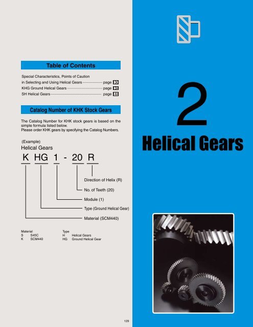
Catalog Number of KHK Stock <strong>Gears</strong><br />
The Catalog Number for KHK stock gears is based on the<br />
simple formula listed below.<br />
Please order KHK gears by specifying the Catalog Numbers.<br />
(Example)<br />
<strong>Helical</strong> <strong>Gears</strong><br />
K HG 1 - 20 R<br />
2<br />
<strong>Helical</strong> <strong>Gears</strong><br />
Direction of Helix (R)<br />
No. of Teeth (20)<br />
Module (1)<br />
Type (Ground <strong>Helical</strong> Gear)<br />
Material (SCM440)<br />
Material<br />
S S45C<br />
K SCM440<br />
Type<br />
H<br />
HG<br />
<strong>Helical</strong> <strong>Gears</strong><br />
Ground <strong>Helical</strong> Gear<br />
129
<strong>Helical</strong> <strong>Gears</strong><br />
Meets all high-speed rotation needs of industrial machines !<br />
Characteristics Selection Hints<br />
KHK stock helical gears are quiet, compact and economical. They<br />
are suitable wherever you require high-speed rotation including in<br />
machine tools, speed reducers and other industrial machinery.<br />
It is important to thoroughly understand the contents of the product<br />
tables as well as “CAUTION” notes before making the selection.<br />
You must specify the right or left hand by including the letter R or<br />
L in the catalog number when ordering.<br />
■ KHG Ground <strong>Helical</strong> <strong>Gears</strong><br />
1 Have excellent strength and wear resistance which allow your<br />
designs to be more compact.<br />
2 Secondary operations are possible permitting modifications to<br />
suit your design.<br />
3 Use of a transverse module allows interchangeability with<br />
straight spur gears of the same module and numbers of teeth<br />
at the same center distance. This feature is very convenient<br />
when switching from spur gears to helical gears due to the gear<br />
strength or the noise considerations.<br />
4 The use of CBN grinding wheels produces consistent precision<br />
with shorter grinding time, making these products easily<br />
affordable.<br />
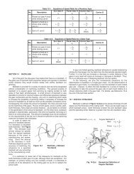
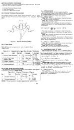
1. Caution in Selecting the Mating <strong>Gears</strong>.<br />
Right hand and left hand helical gears mate as a set. See<br />
the photograph for reference. The table shows the possible<br />
combinations.<br />
■ Mating <strong>Helical</strong> Gear Selection Chart ( ○ Allowable × Not allowable)<br />
Catalog No. &<br />
Helix Hand<br />
KHG<br />
SH<br />
RH<br />
KHG<br />
SH KRHG(F) SRH<br />
RH × ○ × × × ○ × ×<br />
LH<br />
RH<br />
LH<br />
LH RH LH RH LH RH LH<br />
○ × × × ○ × × ×<br />
× × × ○ × × × ○<br />
× × ○ × × × ○ ×<br />
(L) Left<br />
■ SH <strong>Helical</strong> <strong>Gears</strong><br />
1 SH helical gears fit a wide range of applications which have<br />
made them popular choices for many years.<br />
2 Since helical gears have larger contact ratios than the equivalent<br />
SS spur gears, they are effective in reducing noise and vibration.<br />
(R) Right<br />
Pinion (L) & Rack (R)<br />
Pinion (R) & Rack (L)<br />
130
KHK Technical Information<br />
<strong>2.</strong> Caution in Selecting <strong>Gears</strong> Based on Gear Strength<br />
Allowable bending strength and surface durability values shown<br />
in product tables were computed by assuming a certain application<br />
environment. They should be used as reference only. We<br />
recommend that each user computes his own values by applying<br />
the actual usage conditions.<br />
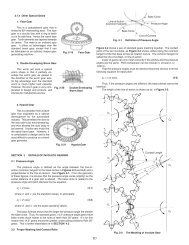
3. Caution with Regard to the Special Characteristics of <strong>Helical</strong> <strong>Gears</strong><br />
1 KHG ground helical gears and SH helical gears are not<br />
interchangeable due to different module systems, pressure angle<br />
designations and helix angles. The illustration below shows the<br />
difference between the transverse module of KHG type and the<br />
normal module of SH type gears.<br />
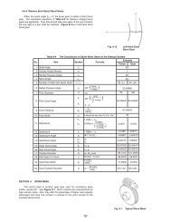
■ Calculation of Bending Strength of <strong>Gears</strong><br />
Item<br />
Catalog No. KHG SH<br />
Formula NOTE 1<br />
Formula of spur and helical gears on bending strength (JGMA401-01)<br />
No. of teeth of mating gears<br />
Same number of teeth<br />
Normal module<br />
Transverse module<br />
Rotation<br />
Durability<br />
Impact from motor<br />
Impact from load<br />
Direction of load<br />
Allowable bending stress at root σFlim NOTE 2<br />
Safety factor SF<br />
600min -1 100min -1<br />
Over 10 7 cycles<br />
Uniform load<br />
Uniform load<br />
Bidirectional<br />
20kgf/mm 2 1<strong>2.</strong>67kgf/mm 2<br />
1.2<br />
CAUTION: Above is for illustration purpose only and not a<br />
representation of the true tooth forms.<br />
2 Since SH helical gears use the normal module, the pitch circle<br />
diameters and the center distance are not integral numbers.<br />
Please refer to the Table of SH <strong>Helical</strong> Gear Center Distance on<br />
the product pages.<br />
■ Calculation of Surface Durability (Except where it is common with bending strength)<br />
Formula NOTE 1<br />
Kinematic viscosity of lubricant<br />
Gear support<br />
Allowable Hertz stress σHlim<br />
Safety factor SH<br />
Formula of spur and helical gears on bending strength (JGMA402-01)<br />
100cSt(50℃ )<br />
Symmetric support by bearings<br />
116kgf/mm 2 49kgf/mm 2<br />
1.15<br />
NOTE 1: The formula for gear strength is based on JGMA Standard. The units<br />
for the rotational speed (min -1 ) and the load (kgf/mm 2 ) were matched<br />
to the units needed in the equation.<br />
NOTE 2: Since the load is bidirectional, the allowable bending stress at root<br />
σFlim is set to 2/3 of the value.<br />
4. Other Points to Consider in Selection Process<br />
1 There are various footnotes to the product pages under the<br />
headings of “CAUTION” and “NOTE”. Please consider them<br />
carefully when selecting these products.<br />
2 There may be slight differences in color or shape of products<br />
shown in the photograph from the actual products.<br />
3 KHK reserves the right to make changes in specifications and<br />
dimensions without notice.<br />
4 KHK is ready to produce and supply custom order products.<br />
When you require specific gears different from KHK Stock<br />
<strong>Gears</strong> please contact our distributor for quotation. Also, please<br />
refer to page 16 “KHK Custom Order Products”.<br />
Definition of bending strength<br />
T h e a l l owa bl e b e n d i n g<br />
strength of a gear is defined<br />
as the allowable tangential<br />
force at the pitch circle<br />
b a s e d o n t h e mutually<br />
allowable root stress of two<br />
meshing gears under load.<br />
Example of the failure due<br />
to insufficient bending<br />
strength.<br />
Definition of surface durability<br />
The surface durability of<br />
a gear is defined as the<br />
allowable tangential force<br />
at the pitch circle, which<br />
permits the force to be<br />
transmitted safely without<br />
incurring surface failure.<br />
Example of the defacement<br />
due to insufficient surface<br />
durability.<br />
131
<strong>Helical</strong> Gear<br />
Application Hints<br />
In order to use KHK stock gears safely, carefully read the<br />
Application Hints before proceeding.<br />
If there are questions or if you require clarifications, please contact<br />
our technical department or your nearest distributor.<br />
KHK CO., LTD. TECHNICAL DEPARTMENT<br />
PHONE: 81-48-254-1744 FAX: 81-48-254-1765<br />
E-mail export@khkgears.co.jp<br />
1. Caution on Performing Secondary Operations<br />
Most KHK gears can be modified by the user. Please note the<br />
following points.<br />
1 If you are reboring, it is important to pay special attention to<br />
locating the center in order to avoid runout.<br />
2 The reference datum for gear cutting is the bore. Therefore,<br />
use the bore for locating the center. If it is too difficult to do for<br />
small bores, the alternative is to use one spot on the bore and the<br />
runout of the side surface.<br />
3 If the rework requires using scroll chucks, we recommend the<br />
use of new or rebored jaws for improved precision. If chucking<br />
by the teeth, please apply the pressure carefully to avoid<br />
crushing the teeth which will lead to noisy gears.<br />
6 To avoid problems of reduced gear precision and other<br />
manufacturing difficulties, do not attempt to machine the gears<br />
to reduce face widths.<br />
7 KHG Ground <strong>Helical</strong> <strong>Gears</strong> are already stress relieved. But if<br />
you subject them to a heavy turning operation such as removing<br />
the hubs, the residual stress may cause deformation.<br />
8 When heat-treating SH <strong>Helical</strong> <strong>Gears</strong>, it is possible to get<br />
thermal stress cracks. It is best to subject them to penetrant<br />
inspection afterwards. If the tooth strength is not sufficient, it<br />
can be increased approximately four times by heat-treating. On<br />
the other hand, the precision of the gear will drop about one<br />
grade.<br />
Lathe Operations<br />
Heat Treatment<br />
1) Induction Heat treatment of S45C products should<br />
conform with the reference data below.<br />
●Heat treatment temperature - 800~900°C<br />
●Tempering temperature - 200~250°C<br />
●Hardness -<br />
48~53HRC<br />
2) In general, gears made from S45C have not been heattreated.<br />
The user can heat-treat as required, but some<br />
deformation will be introduced. Ordinarily, a grinding<br />
process is needed after heat-treatment. Otherwise, the<br />
precision grade will drop about one grade.<br />
3) SUS303 and SUS304 belong to austenite family and<br />
cannot be hardened. To harden stainless, there are<br />
martensitic series, such as SUS420J<strong>2.</strong><br />
4) The induction hardened depth is approximately 1mm.<br />
However, the hardening process does not completely<br />
reach the root of the gear tooth at the center portion of<br />
the face width.<br />
4 The maximum bore size is dictated by the requirement that the<br />
strength of the hub must be higher than that of the gear teeth.<br />
5 In order to avoid stress concentrations, leave radii on the<br />
keyway corners.<br />
132
KHK Technical Information<br />
<strong>2.</strong> Points of Caution in Assembling<br />
1 KHK stock helical gears are designed to give the proper<br />
backlash when assembled using the center distance given by the<br />
formula on the right (center distance tolerance of H7~H8). The<br />
amount of backlash is given in the product table for each gear.<br />
2 Because of the helix of the gear teeth, helical gears in mesh<br />
produce thrust forces in the axial directions. The axial thrust<br />
bearings must be able to resist these forces. The direction of<br />
the thrust forces depend on the helix hand and the direction of<br />
rotation as shown below<br />
3 Please refer to overall length tolerance for <strong>Helical</strong> <strong>Gears</strong> on page<br />
30.<br />
a=<br />
d1 + d2<br />
2<br />
where<br />
a = center distance<br />
d1 = pitch diameter of pinion<br />
d2 = pitch diameter of gear<br />
CAUTION:<br />
The center distance of<br />
SH series is given in a<br />
separate table.<br />
Direction of rotation and<br />
thrust force<br />
L<br />
driven<br />
L<br />
L<br />
drive<br />
L<br />
R<br />
drive<br />
R<br />
R<br />
driven<br />
R<br />
Thrust bearing<br />
R Rack thrust<br />
L Pinion thrust<br />
R Pinion thrust<br />
L Rack thrust<br />
L Pinion thrust<br />
drive<br />
R Rack thrust<br />
L Rack thrust<br />
drive<br />
R pinion thrust<br />
3. Notes on Starting Operations<br />
1 Before operating, check the following:<br />
● Are the gears firmly mounted on the shafts?<br />
● Have you eliminated uneven tooth contact?<br />
● Does the gear mesh have the proper amount of backlash?<br />
(Please avoid the condition of no backlash.)<br />
● Is there sufficient lubrication?<br />
2 If the gears are exposed, install a safety cover for protection.<br />
Never touch gears while they are in motion.<br />
3 If there is unusual noise or vibration at the start up or<br />
insufficient lubrication after the start up, please recheck the<br />
gears and correctness of the assembly. Some of the methods for<br />
achieving noise reduction are:<br />
(a) High Precision<br />
(b) Fine Tooth Surface Finish<br />
(c) Accurate Tooth Contact<br />
4 The followings are the gear lubrication methods in general use:<br />
(a) Grease Lubrication<br />
(b) Splash Lubrication (Oil Bath Method)<br />
(c) Forced Oil Circulation Lubrication<br />
Check lubrication after start up. Sometimes, when the unit is<br />
initially being operated, lubricating oil deteriorates rapidly.<br />
4. Other Points to Consider in Applications<br />
1 KHK products are individually packaged to avoid damage.<br />
Depending on how they are handled, it is still possible to deform<br />
or break them. It is important to exercise care in handling these<br />
parts.<br />
2 Check the products as they are being taken out of the boxes. If<br />
any of them are rusted, scratched or dented, please return to the<br />
dealer where they were bought, for exchange.<br />
3 KHK cannot guarantee the precision of gears once the customer<br />
performs a secondary operation on them.<br />
133
KHG Ground <strong>Helical</strong> <strong>Gears</strong><br />
Transverse<br />
Module 1<br />
<strong>Helical</strong><br />
<strong>Gears</strong><br />
K<br />
H<br />
G<br />
RH<br />
S1 Shape<br />
LH<br />
■ Module 1<br />
Catalog No. Module No. of teeth Direction<br />
of helix<br />
KHG1-20R<br />
KHG1-20L<br />
KHG1-22R<br />
KHG1-22L<br />
KHG1-24R<br />
KHG1-24L<br />
KHG1-25R<br />
KHG1-25L<br />
KHG1-28R<br />
KHG1-28L<br />
KHG1-30R<br />
KHG1-30L<br />
KHG1-32R<br />
KHG1-32L<br />
KHG1-35R<br />
KHG1-35L<br />
KHG1-36R<br />
KHG1-36L<br />
KHG1-40R<br />
KHG1-40L<br />
KHG1-44R<br />
KHG1-44L<br />
KHG1-45R<br />
KHG1-45L<br />
KHG1-48R<br />
KHG1-48L<br />
KHG1-50R<br />
KHG1-50L<br />
KHG1-60R<br />
KHG1-60L<br />
KHG1-70R<br />
KHG1-70L<br />
KHG1-80R<br />
KHG1-80L<br />
KHG1-90R<br />
KHG1-90L<br />
KHG1-100R<br />
KHG1-100L<br />
m1<br />
20<br />
22<br />
24<br />
25<br />
28<br />
30<br />
32<br />
35<br />
36<br />
40<br />
44<br />
45<br />
48<br />
50<br />
60<br />
70<br />
80<br />
90<br />
100<br />
R<br />
L<br />
R<br />
L<br />
R<br />
L<br />
R<br />
L<br />
R<br />
L<br />
R<br />
L<br />
R<br />
L<br />
R<br />
L<br />
R<br />
L<br />
R<br />
L<br />
R<br />
L<br />
R<br />
L<br />
R<br />
L<br />
R<br />
L<br />
R<br />
L<br />
R<br />
L<br />
R<br />
L<br />
R<br />
L<br />
R<br />
L<br />
Shape<br />
Bore Hub dia. Pitch dia. Outside dia. Face width NOTE 1 Hub width Total length<br />
AH7 B C D E F G<br />
S1 6 17 20 22 8 10 18<br />
S1 8 18 22 24 8 10 18<br />
S1 8 20 24 26 8 10 18<br />
S1 8 20 25 27 8 10 18<br />
S1 8 20 28 30 8 10 18<br />
S1 10 25 30 32 8 10 18<br />
S1 10 25 32 34 8 10 18<br />
S1 10 25 35 37 8 10 18<br />
S1 10 25 36 38 8 10 18<br />
S1 10 30 40 42 8 10 18<br />
S1 10 30 44 46 8 10 18<br />
S1 10 30 45 47 8 10 18<br />
S1 10 30 48 50 8 10 18<br />
S1 12 35 50 52 8 10 18<br />
S1 12 40 60 62 8 10 18<br />
S1 12 40 70 72 8 10 18<br />
S1 15 50 80 82 8 10 18<br />
S1 15 50 90 92 8 10 18<br />
S1 15 50 100 102 8 10 18<br />
CAUTION: Right handed and left handed helical gears of the same module are designed to mesh as a pair, but they are not interchangeable with SH type helical gears.<br />
NOTE 1: It is possible to perform secondary operations except on the gear teeth. We recommend that you avoid shortening the hub which will lead to the deformation of the<br />
gears.<br />
134
Ground <strong>Helical</strong> <strong>Gears</strong><br />
Specifications<br />
Precision grade<br />
Reference section<br />
of gear<br />
Gear teeth<br />
JIS N6 grade (JIS B1702-1: 1998)<br />
OLD JIS 2 grade (JIS B1702: 1976)<br />
Rotating plane<br />
Standard full depth<br />
Heat treatment<br />
Tooth hardness<br />
Surface treatment<br />
Thermal refined, tooth surfaces<br />
induction hardened<br />
50~55HRC<br />
Black oxide except ground surfaces<br />
<strong>Helical</strong><br />
<strong>Gears</strong><br />
Transverse pressure<br />
angle<br />
Helix angle<br />
20°<br />
21°30’<br />
Tooth surface finish<br />
Datum reference surface<br />
for gear grinding<br />
Ground<br />
Bore<br />
K<br />
H<br />
G<br />
Material<br />
SCM440<br />
Secondary Operations<br />
Possible except tooth area<br />
Allowable torque(N・m) NOTE 2 Allowable torque(kgf・m) Backlash<br />
Bending strength Surface durability Bending strength Surface durability<br />
(mm)NOTE 3<br />
Weight<br />
(kg)<br />
7.79 4.98 0.79 0.51 0.08~0.16 0.03<br />
8.92 6.14 0.91 0.63 0.08~0.16 0.04<br />
10.1 7.43 1.03 0.76 0.08~0.16 0.05<br />
10.7 8.12 1.09 0.83 0.08~0.16 0.05<br />
1<strong>2.</strong>4 10.4 1.27 1.06 0.08~0.16 0.06<br />
13.6 1<strong>2.</strong>1 1.39 1.23 0.08~0.16 0.07<br />
13.5 1<strong>2.</strong>6 1.37 1.29 0.08~0.16 0.08<br />
15.1 15.4 1.54 1.57 0.08~0.16 0.09<br />
15.7 16.3 1.60 1.67 0.08~0.16 0.09<br />
17.9 20.5 1.83 <strong>2.</strong>10 0.08~0.16 0.12<br />
20.2 25.3 <strong>2.</strong>06 <strong>2.</strong>58 0.08~0.16 0.14<br />
20.7 26.5 <strong>2.</strong>12 <strong>2.</strong>71 0.08~0.16 0.14<br />
2<strong>2.</strong>5 30.5 <strong>2.</strong>29 3.11 0.08~0.16 0.16<br />
23.6 33.3 <strong>2.</strong>41 3.40 0.08~0.16 0.18<br />
29.3 49.4 <strong>2.</strong>99 5.04 0.10~0.18 0.26<br />
35.2 68.9 3.58 7.02 0.10~0.18 0.32<br />
41.0 91.8 4.18 9.36 0.10~0.18 0.44<br />
46.9 118 4.78 1<strong>2.</strong>1 0.10~0.18 0.53<br />
50.4 142 5.14 14.5 0.10~0.18 0.62<br />
Catalog No.<br />
KHG1-20R<br />
KHG1-20L<br />
KHG1-22R<br />
KHG1-22L<br />
KHG1-24R<br />
KHG1-24L<br />
KHG1-25R<br />
KHG1-25L<br />
KHG1-28R<br />
KHG1-28L<br />
KHG1-30R<br />
KHG1-30L<br />
KHG1-32R<br />
KHG1-32L<br />
KHG1-35R<br />
KHG1-35L<br />
KHG1-36R<br />
KHG1-36L<br />
KHG1-40R<br />
KHG1-40L<br />
KHG1-44R<br />
KHG1-44L<br />
KHG1-45R<br />
KHG1-45L<br />
KHG1-48R<br />
KHG1-48L<br />
KHG1-50R<br />
KHG1-50L<br />
KHG1-60R<br />
KHG1-60L<br />
KHG1-70R<br />
KHG1-70L<br />
KHG1-80R<br />
KHG1-80L<br />
KHG1-90R<br />
KHG1-90L<br />
KHG1-100R<br />
KHG1-100L<br />
NOTE 2: The allowable torques shown in the table are the calculated values according to the assumed usage conditions.<br />
Please see page 131 for more details.<br />
NOTE 3: The backlash values shown in the table are the theoretical values of a pair of identical gears in mesh.<br />
135
KHG Ground <strong>Helical</strong> <strong>Gears</strong><br />
Transverse<br />
Module 1.5<br />
<strong>Helical</strong><br />
<strong>Gears</strong><br />
K<br />
H<br />
G<br />
■ Module 1.5<br />
RH<br />
S1 Shape<br />
LH<br />
Catalog No. Module No. of teeth Direction<br />
Bore Hub dia. Pitch dia. Outside dia. Face width NOTE 1 Hub width Total length<br />
Shape<br />
of helix<br />
AH7 B C D E F G<br />
KHG1.5-20R<br />
R<br />
20<br />
KHG1.5-20L<br />
L<br />
S1 12 24 30 33 12 12 24<br />
KHG1.5-22R<br />
R<br />
22<br />
KHG1.5-22L<br />
L<br />
S1 12 26 33 36 12 12 24<br />
KHG1.5-24R<br />
R<br />
24<br />
KHG1.5-24L<br />
L<br />
S1 12 28 36 39 12 12 24<br />
KHG1.5-25R<br />
R<br />
25<br />
KHG1.5-25L<br />
L<br />
S1 12 30 37.5 40.5 12 12 24<br />
KHG1.5-26R<br />
R<br />
26<br />
KHG1.5-26L<br />
L<br />
S1 12 32 39 42 12 12 24<br />
KHG1.5-28R<br />
R<br />
28<br />
KHG1.5-28L<br />
L<br />
S1 15 36 42 45 12 12 24<br />
KHG1.5-30R<br />
R<br />
30<br />
KHG1.5-30L<br />
L<br />
S1 15 38 45 48 12 12 24<br />
KHG1.5-32R<br />
R<br />
32<br />
KHG1.5-32L<br />
L<br />
S1 15 40 48 51 12 12 24<br />
KHG1.5-35R<br />
R<br />
35<br />
KHG1.5-35L<br />
L<br />
S1 15 42 5<strong>2.</strong>5 55.5 12 12 24<br />
KHG1.5-36R<br />
R<br />
36<br />
KHG1.5-36L<br />
L<br />
S1 15 45 54 57 12 12 24<br />
KHG1.5-40R<br />
R<br />
m1.5 40<br />
KHG1.5-40L<br />
L<br />
S1 15 50 60 63 12 12 24<br />
KHG1.5-44R<br />
R<br />
44<br />
KHG1.5-44L<br />
L<br />
S1 15 50 66 69 12 12 24<br />
KHG1.5-45R<br />
R<br />
45<br />
KHG1.5-45L<br />
L<br />
S1 18 50 67.5 70.5 12 12 24<br />
KHG1.5-48R<br />
R<br />
48<br />
KHG1.5-48L<br />
L<br />
S1 18 50 72 75 12 12 24<br />
KHG1.5-50R<br />
R<br />
50<br />
KHG1.5-50L<br />
L<br />
S1 18 60 75 78 12 12 24<br />
KHG1.5-52R<br />
R<br />
52<br />
KHG1.5-52L<br />
L<br />
S1 18 60 78 81 12 12 24<br />
KHG1.5-60R<br />
R<br />
60<br />
KHG1.5-60L<br />
L<br />
S1 20 60 90 93 12 12 24<br />
KHG1.5-70R<br />
R<br />
70<br />
KHG1.5-70L<br />
L<br />
S1 20 60 105 108 12 12 24<br />
KHG1.5-80R<br />
R<br />
80<br />
KHG1.5-80L<br />
L<br />
S1 20 70 120 123 12 12 24<br />
KHG1.5-90R<br />
R<br />
90<br />
KHG1.5-90L<br />
L<br />
S1 20 70 135 138 12 12 24<br />
KHG1.5-100R<br />
R<br />
100<br />
KHG1.5-100L<br />
L<br />
S1 20 70 150 153 12 12 24<br />
CAUTION: Right handed and left handed helical gears in the same module are designed to mesh as a pair, but they are not interchangeable with SH type helical gears.<br />
NOTE 1: It is possible to perform secondary operations except on the gear teeth. We recommend that you avoid shortening the hub which will lead to the deformation of the gears.<br />
136
Ground <strong>Helical</strong> <strong>Gears</strong><br />
Specifications<br />
Precision grade<br />
Reference section<br />
of gear<br />
Gear teeth<br />
JIS N6 grade (JIS B1702-1: 1998)<br />
OLD JIS 2 grade (JIS B1702: 1976)<br />
Rotating plane<br />
Standard full depth<br />
Heat treatment<br />
Tooth hardness<br />
Surface treatment<br />
Thermal refined, tooth surfaces<br />
induction hardened<br />
50~55HRC<br />
Black oxide except ground surfaces<br />
<strong>Helical</strong><br />
<strong>Gears</strong><br />
Transverse pressure<br />
angle<br />
Helix angle<br />
20°<br />
21°30’<br />
Tooth surface finish<br />
Datum reference surface<br />
for gear grinding<br />
Ground<br />
Bore<br />
K<br />
H<br />
G<br />
Material<br />
SCM440<br />
Secondary Operations<br />
Possible except tooth area<br />
Allowable torque(N・m) Allowable torque(kgf・m) Backlash Weight<br />
Bending strength Surface durability Bending strength Surface durability (mm)NOTE 3<br />
(kg)<br />
26.3 18.5 <strong>2.</strong>68 1.89 0.08~0.16 0.09<br />
27.4 20.8 <strong>2.</strong>79 <strong>2.</strong>12 0.08~0.16 0.11<br />
30.9 25.3 3.15 <strong>2.</strong>58 0.08~0.16 0.13<br />
3<strong>2.</strong>7 27.7 3.33 <strong>2.</strong>83 0.08~0.16 0.15<br />
34.5 30.2 3.52 3.08 0.08~0.16 0.17<br />
38.1 35.7 3.89 3.64 0.08~0.16 0.19<br />
41.8 41.6 4.26 4.24 0.08~0.16 0.22<br />
45.5 48.0 4.64 4.89 0.08~0.16 0.26<br />
51.1 58.5 5.21 5.96 0.10~0.18 0.30<br />
5<strong>2.</strong>9 6<strong>2.</strong>2 5.40 6.35 0.10~0.18 0.33<br />
60.5 78.5 6.17 8.00 0.10~0.18 0.42<br />
68.1 96.8 6.95 9.87 0.10~0.18 0.47<br />
70.0 102 7.14 10.4 0.10~0.18 0.47<br />
75.8 117 7.73 1<strong>2.</strong>0 0.10~0.18 0.52<br />
79.6 128 8.12 13.1 0.10~0.18 0.63<br />
83.5 140 8.51 14.2 0.10~0.18 0.67<br />
99.1 191 10.1 19.5 0.10~0.18 0.81<br />
114 256 11.6 26.1 0.12~0.20 1.00<br />
132 343 13.5 35.0 0.12~0.20 1.40<br />
151 442 15.4 45.1 0.12~0.20 1.65<br />
170 554 17.4 56.5 0.12~0.20 1.97<br />
Catalog No.<br />
KHG1.5-20R<br />
KHG1.5-20L<br />
KHG1.5-22R<br />
KHG1.5-22L<br />
KHG1.5-24R<br />
KHG1.5-24L<br />
KHG1.5-25R<br />
KHG1.5-25L<br />
KHG1.5-26R<br />
KHG1.5-26L<br />
KHG1.5-28R<br />
KHG1.5-28L<br />
KHG1.5-30R<br />
KHG1.5-30L<br />
KHG1.5-32R<br />
KHG1.5-32L<br />
KHG1.5-35R<br />
KHG1.5-35L<br />
KHG1.5-36R<br />
KHG1.5-36L<br />
KHG1.5-40R<br />
KHG1.5-40L<br />
KHG1.5-44R<br />
KHG1.5-44L<br />
KHG1.5-45R<br />
KHG1.5-45L<br />
KHG1.5-48R<br />
KHG1.5-48L<br />
KHG1.5-50R<br />
KHG1.5-50L<br />
KHG1.5-52R<br />
KHG1.5-52L<br />
KHG1.5-60R<br />
KHG1.5-60L<br />
KHG1.5-70R<br />
KHG1.5-70L<br />
KHG1.5-80R<br />
KHG1.5-80L<br />
KHG1.5-90R<br />
KHG1.5-90L<br />
KHG1.5-100R<br />
KHG1.5-100L<br />
137<br />
NOTE 2: The allowable torques shown in the table are the<br />
calculated values according to the assumed usage<br />
conditions. Please see page 131 for more details.<br />
NOTE 3: The backlash values shown in the table are the<br />
theoretical values of a pair of identical gears in mesh.
KHG Ground <strong>Helical</strong> <strong>Gears</strong> Transverse<br />
Module<br />
2<br />
<strong>Helical</strong><br />
<strong>Gears</strong><br />
K<br />
H<br />
G<br />
■ Module 2<br />
RH<br />
S1 Shape<br />
LH<br />
Catalog No. Module No. of teeth Direction<br />
of helix<br />
Shape<br />
Bore Hub dia. Pitch dia. Outside dia. Face width NOTE 1 Hub width Total length<br />
AH7 B C D E F G<br />
KHG2-15R<br />
R<br />
15<br />
KHG2-15L<br />
L<br />
S1 12 24 30 34 16 13 29<br />
KHG2-16R<br />
R<br />
16<br />
KHG2-16L<br />
L<br />
S1 12 26 32 36 16 13 29<br />
KHG2-18R<br />
R<br />
18<br />
KHG2-18L<br />
L<br />
S1 12 30 36 40 16 13 29<br />
KHG2-20R<br />
R<br />
20<br />
KHG2-20L<br />
L<br />
S1 15 32 40 44 16 13 29<br />
KHG2-22R<br />
R<br />
22<br />
KHG2-22L<br />
L<br />
S1 15 36 44 48 16 13 29<br />
KHG2-24R<br />
R<br />
24<br />
KHG2-24L<br />
L<br />
S1 15 38 48 52 16 13 29<br />
KHG2-25R<br />
R<br />
25<br />
KHG2-25L<br />
L<br />
S1 15 40 50 54 16 13 29<br />
KHG2-26R<br />
R<br />
26<br />
KHG2-26L<br />
L<br />
S1 15 42 52 56 16 13 29<br />
KHG2-28R<br />
R<br />
28<br />
KHG2-28L<br />
L<br />
S1 15 45 56 60 16 13 29<br />
KHG2-30R<br />
R<br />
30<br />
KHG2-30L<br />
L<br />
S1 18 50 60 64 16 13 29<br />
KHG2-32R<br />
R<br />
32<br />
KHG2-32L<br />
L<br />
S1 18 50 64 68 16 13 29<br />
KHG2-35R<br />
R<br />
35<br />
S1 18 50 70 74 16 13 29<br />
KHG2-35L<br />
L<br />
m2<br />
KHG2-36R<br />
R<br />
36<br />
S1 18 50 72 76 16 13 29<br />
KHG2-36L<br />
L<br />
KHG2-40R<br />
R<br />
40<br />
KHG2-40L<br />
L<br />
S1 20 60 80 84 16 13 29<br />
KHG2-44R<br />
R<br />
44<br />
KHG2-44L<br />
L<br />
S1 20 60 88 92 16 13 29<br />
KHG2-45R<br />
R<br />
45<br />
KHG2-45L<br />
L<br />
S1 20 60 90 94 16 13 29<br />
KHG2-48R<br />
R<br />
48<br />
KHG2-48L<br />
L<br />
S1 20 60 96 100 16 13 29<br />
KHG2-50R<br />
R<br />
50<br />
KHG2-50L<br />
L<br />
S1 25 60 100 104 16 13 29<br />
KHG2-52R<br />
R<br />
52<br />
KHG2-52L<br />
L<br />
S1 25 65 104 108 16 13 29<br />
KHG2-60R<br />
R<br />
60<br />
KHG2-60L<br />
L<br />
S1 25 65 120 124 16 13 29<br />
KHG2-70R<br />
R<br />
70<br />
KHG2-70L<br />
L<br />
S1 25 70 140 144 16 13 29<br />
KHG2-80R<br />
R<br />
80<br />
KHG2-80L<br />
L<br />
S1 25 80 160 164 16 13 29<br />
KHG2-90R<br />
R<br />
90<br />
KHG2-90L<br />
L<br />
S1 25 90 180 184 16 13 29<br />
KHG2-100R<br />
R<br />
100<br />
KHG2-100L<br />
L<br />
S1 25 100 200 204 16 13 29<br />
CAUTION: Right handed and left handed helical gears in the same module are designed to mesh as a pair, but they are not interchangeable with SH type helical gears.<br />
NOTE 1: It is possible to perform secondary operations except on the gear teeth. We recommend that you avoid shortening the hub which will lead to the deformation of the gears.<br />
138
Ground <strong>Helical</strong> <strong>Gears</strong><br />
Specifications<br />
Precision grade<br />
Reference section<br />
of gear<br />
Gear teeth<br />
Transverse pressure<br />
angle<br />
Helix angle<br />
Material<br />
JIS N6 grade (JIS B1702-1: 1998)<br />
OLD JIS 2 grade (JIS B1702: 1976)<br />
Rotating plane<br />
Standard full depth<br />
20°<br />
21°30’<br />
SCM440<br />
Heat treatment<br />
Tooth hardness<br />
Surface treatment<br />
Tooth surface finish<br />
Datum reference surface<br />
for gear grinding<br />
Secondary Operations<br />
Thermal refined, tooth surfaces<br />
induction hardened<br />
50~55HRC<br />
Black oxide except ground surfaces<br />
Ground<br />
Bore<br />
Possible except tooth area<br />
<strong>Helical</strong><br />
<strong>Gears</strong><br />
K<br />
H<br />
G<br />
Allowable torque(N・m) NOTE 2 Allowable torque(kgf・m) Backlash Weight<br />
Bending strength Surface durability Bending strength Surface durability (mm)NOTE 3 (kg)<br />
Catalog No.<br />
40.5 2<strong>2.</strong>8 4.13 <strong>2.</strong>32 0.10~0.20 0.11<br />
KHG2-15R<br />
KHG2-15L<br />
40.6 24.1 4.14 <strong>2.</strong>46 0.10~0.20 0.13<br />
KHG2-16R<br />
KHG2-16L<br />
48.5 31.9 4.95 3.25 0.10~0.20 0.17<br />
KHG2-18R<br />
KHG2-18L<br />
56.6 40.8 5.77 4.16 0.10~0.20 0.20<br />
KHG2-20R<br />
KHG2-20L<br />
64.9 50.6 6.62 5.16 0.10~0.20 0.25<br />
KHG2-22R<br />
KHG2-22L<br />
73.3 61.4 7.47 6.26 0.10~0.20 0.30<br />
KHG2-24R<br />
KHG2-24L<br />
77.5 67.3 7.90 6.86 0.10~0.20 0.33<br />
KHG2-25R<br />
KHG2-25L<br />
81.8 73.4 8.34 7.49 0.12~0.22 0.37<br />
KHG2-26R<br />
KHG2-26L<br />
90.4 86.6 9.21 8.83 0.12~0.22 0.43<br />
KHG2-28R<br />
KHG2-28L<br />
99.1 101 10.1 10.3 0.12~0.22 0.50<br />
KHG2-30R<br />
KHG2-30L<br />
108 117 11.0 11.9 0.12~0.22 0.55<br />
KHG2-32R<br />
KHG2-32L<br />
121 142 1<strong>2.</strong>3 14.5 0.12~0.22 0.63<br />
KHG2-35R<br />
KHG2-35L<br />
126 151 1<strong>2.</strong>8 15.4 0.12~0.22 0.65<br />
KHG2-36R<br />
KHG2-36L<br />
143 191 14.6 19.5 0.12~0.22 0.85<br />
KHG2-40R<br />
KHG2-40L<br />
161 236 16.5 24.0 0.12~0.22 0.98<br />
KHG2-44R<br />
KHG2-44L<br />
166 248 16.9 25.3 0.12~0.22 1.00<br />
KHG2-45R<br />
KHG2-45L<br />
172 273 17.5 27.9 0.12~0.22 1.10<br />
KHG2-48R<br />
KHG2-48L<br />
181 299 18.4 30.5 0.12~0.22 1.20<br />
KHG2-50R<br />
KHG2-50L<br />
189 326 19.3 33.2 0.14~0.24 1.29<br />
KHG2-52R<br />
KHG2-52L<br />
225 447 2<strong>2.</strong>9 45.6 0.14~0.24 1.60<br />
KHG2-60R<br />
KHG2-60L<br />
269 625 27.4 63.7 0.14~0.24 <strong>2.</strong>20<br />
KHG2-70R<br />
KHG2-70L<br />
301 799 30.7 81.4 0.14~0.24 <strong>2.</strong>90<br />
KHG2-80R<br />
KHG2-80L<br />
344 1030 35.0 105 0.14~0.24 3.37<br />
KHG2-90R<br />
KHG2-90L<br />
387 1290 39.4 132 0.14~0.24 4.63<br />
KHG2-100R<br />
KHG2-100L<br />
NOTE 2: The allowable torques shown in the table are the calculated values according to the assumed usage conditions. Please see page 131 for more details.<br />
NOTE 3: The backlash values shown in the table are the theoretical values of a pair of identical gears in mesh.<br />
139
KHG Ground <strong>Helical</strong> <strong>Gears</strong><br />
Transverse<br />
Module <strong>2.</strong>5<br />
<strong>Helical</strong><br />
<strong>Gears</strong><br />
K<br />
H<br />
G<br />
RH<br />
S1 Shape<br />
LH<br />
■ Module <strong>2.</strong>5<br />
Catalog No. Module No. of teeth Direction<br />
of helix<br />
KHG<strong>2.</strong>5-15R<br />
KHG<strong>2.</strong>5-15L<br />
KHG<strong>2.</strong>5-16R<br />
KHG<strong>2.</strong>5-16L<br />
KHG<strong>2.</strong>5-18R<br />
KHG<strong>2.</strong>5-18L<br />
KHG<strong>2.</strong>5-20R<br />
KHG<strong>2.</strong>5-20L<br />
KHG<strong>2.</strong>5-22R<br />
KHG<strong>2.</strong>5-22L<br />
KHG<strong>2.</strong>5-24R<br />
KHG<strong>2.</strong>5-24L<br />
KHG<strong>2.</strong>5-25R<br />
KHG<strong>2.</strong>5-25L<br />
KHG<strong>2.</strong>5-26R<br />
KHG<strong>2.</strong>5-26L<br />
KHG<strong>2.</strong>5-28R<br />
KHG<strong>2.</strong>5-28L<br />
KHG<strong>2.</strong>5-30R<br />
KHG<strong>2.</strong>5-30L<br />
KHG<strong>2.</strong>5-32R<br />
KHG<strong>2.</strong>5-32L<br />
KHG<strong>2.</strong>5-35R<br />
KHG<strong>2.</strong>5-35L<br />
KHG<strong>2.</strong>5-36R<br />
KHG<strong>2.</strong>5-36L<br />
KHG<strong>2.</strong>5-40R<br />
KHG<strong>2.</strong>5-40L<br />
KHG<strong>2.</strong>5-44R<br />
KHG<strong>2.</strong>5-44L<br />
KHG<strong>2.</strong>5-45R<br />
KHG<strong>2.</strong>5-45L<br />
KHG<strong>2.</strong>5-48R<br />
KHG<strong>2.</strong>5-48L<br />
KHG<strong>2.</strong>5-50R<br />
KHG<strong>2.</strong>5-50L<br />
KHG<strong>2.</strong>5-52R<br />
KHG<strong>2.</strong>5-52L<br />
KHG<strong>2.</strong>5-60R<br />
KHG<strong>2.</strong>5-60L<br />
m<strong>2.</strong>5<br />
15<br />
16<br />
18<br />
20<br />
22<br />
24<br />
25<br />
26<br />
28<br />
30<br />
32<br />
35<br />
36<br />
40<br />
44<br />
45<br />
48<br />
50<br />
52<br />
60<br />
R<br />
L<br />
R<br />
L<br />
R<br />
L<br />
R<br />
L<br />
R<br />
L<br />
R<br />
L<br />
R<br />
L<br />
R<br />
L<br />
R<br />
L<br />
R<br />
L<br />
R<br />
L<br />
R<br />
L<br />
R<br />
L<br />
R<br />
L<br />
R<br />
L<br />
R<br />
L<br />
R<br />
L<br />
R<br />
L<br />
R<br />
L<br />
R<br />
L<br />
Shape<br />
Bore Hub dia. Pitch dia. Outside dia. Face width NOTE 1 Hub width Total length<br />
AH7 B C D E F G<br />
S1 15 30 37.5 4<strong>2.</strong>5 20 14 34<br />
S1 15 32 40 45 20 14 34<br />
S1 15 38 45 50 20 14 34<br />
S1 18 40 50 55 20 14 34<br />
S1 18 44 55 60 20 14 34<br />
S1 18 48 60 65 20 14 34<br />
S1 20 50 6<strong>2.</strong>5 67.5 20 14 34<br />
S1 20 50 65 70 20 14 34<br />
S1 20 60 70 75 20 14 34<br />
S1 20 65 75 80 20 14 34<br />
S1 20 70 80 85 20 14 34<br />
S1 20 70 87.5 9<strong>2.</strong>5 20 14 34<br />
S1 20 70 90 95 20 14 34<br />
S1 25 70 100 105 20 14 34<br />
S1 25 75 110 115 20 14 34<br />
S1 25 75 11<strong>2.</strong>5 117.5 20 14 34<br />
S1 25 75 120 125 20 14 34<br />
S1 25 80 125 130 20 14 34<br />
S1 25 80 130 135 20 14 34<br />
S1 25 80 150 155 20 14 34<br />
CAUTION: Right handed and left handed helical gears in the same module are designed to mesh as a pair, but they are not interchangeable with SH type helical gears.<br />
NOTE 1: It is possible to perform secondary operations except on the gear teeth. We recommend that you avoid shortening the hub which will lead to the deformation of the gears.<br />
140
Ground <strong>Helical</strong> <strong>Gears</strong><br />
Specifications<br />
Precision grade<br />
Reference section<br />
of gear<br />
Gear teeth<br />
JIS N6 grade (JIS B1702-1: 1998)<br />
OLD JIS 2 grade (JIS B1702: 1976)<br />
Rotating plane<br />
Standard full depth<br />
Heat treatment<br />
Tooth hardness<br />
Surface treatment<br />
Thermal refined, tooth surfaces<br />
induction hardened<br />
50~55HRC<br />
Black oxide except ground surfaces<br />
<strong>Helical</strong><br />
<strong>Gears</strong><br />
Transverse pressure<br />
angle<br />
Helix angle<br />
20°<br />
21°30’<br />
Tooth surface finish<br />
Datum reference surface<br />
for gear grinding<br />
Ground<br />
Bore<br />
K<br />
H<br />
G<br />
Material<br />
SCM440<br />
Secondary Operations<br />
Possible except tooth area<br />
Allowable torque(N・m) NOTE 2 Allowable torque(kgf・m) Backlash<br />
Bending strength Surface durability Bending strength Surface durability<br />
(mm)NOTE 3<br />
Weight<br />
(kg)<br />
71.8 41.1 7.32 4.19 0.10~0.20 0.21<br />
79.4 47.9 8.09 4.89 0.10~0.20 0.25<br />
94.8 63.4 9.67 6.47 0.10~0.20 0.34<br />
111 81.3 11.3 8.29 0.10~0.20 0.39<br />
127 101 1<strong>2.</strong>9 10.3 0.12~0.22 0.49<br />
143 122 14.6 1<strong>2.</strong>5 0.12~0.22 0.60<br />
151 134 15.4 13.7 0.12~0.22 0.64<br />
160 146 16.3 14.9 0.12~0.22 0.65<br />
176 173 18.0 17.6 0.12~0.22 0.87<br />
193 201 19.7 20.5 0.12~0.22 1.00<br />
211 232 21.5 23.7 0.12~0.22 1.20<br />
236 284 24.1 28.9 0.12~0.22 1.30<br />
245 302 25.0 30.8 0.12~0.22 1.40<br />
268 365 27.3 37.2 0.12~0.22 1.60<br />
302 451 30.8 46.0 0.14~0.24 1.90<br />
310 474 31.6 48.3 0.14~0.24 <strong>2.</strong>00<br />
336 547 34.2 55.8 0.14~0.24 <strong>2.</strong>20<br />
353 599 36.0 61.0 0.14~0.24 <strong>2.</strong>40<br />
370 652 37.7 66.5 0.14~0.24 <strong>2.</strong>50<br />
439 890 44.7 90.8 0.14~0.24 3.30<br />
NOTE 2: The allowable torques shown in the table are the calculated values according to the assumed usage conditions.<br />
Please see page 131 for more details.<br />
NOTE 3: The backlash values shown in the table are the theoretical values of a pair of identical gears in mesh.<br />
141<br />
Catalog No.<br />
KHG<strong>2.</strong>5-15R<br />
KHG<strong>2.</strong>5-15L<br />
KHG<strong>2.</strong>5-16R<br />
KHG<strong>2.</strong>5-16L<br />
KHG<strong>2.</strong>5-18R<br />
KHG<strong>2.</strong>5-18L<br />
KHG<strong>2.</strong>5-20R<br />
KHG<strong>2.</strong>5-20L<br />
KHG<strong>2.</strong>5-22R<br />
KHG<strong>2.</strong>5-22L<br />
KHG<strong>2.</strong>5-24R<br />
KHG<strong>2.</strong>5-24L<br />
KHG<strong>2.</strong>5-25R<br />
KHG<strong>2.</strong>5-25L<br />
KHG<strong>2.</strong>5-26R<br />
KHG<strong>2.</strong>5-26L<br />
KHG<strong>2.</strong>5-28R<br />
KHG<strong>2.</strong>5-28L<br />
KHG<strong>2.</strong>5-30R<br />
KHG<strong>2.</strong>5-30L<br />
KHG<strong>2.</strong>5-32R<br />
KHG<strong>2.</strong>5-32L<br />
KHG<strong>2.</strong>5-35R<br />
KHG<strong>2.</strong>5-35L<br />
KHG<strong>2.</strong>5-36R<br />
KHG<strong>2.</strong>5-36L<br />
KHG<strong>2.</strong>5-40R<br />
KHG<strong>2.</strong>5-40L<br />
KHG<strong>2.</strong>5-44R<br />
KHG<strong>2.</strong>5-44L<br />
KHG<strong>2.</strong>5-45R<br />
KHG<strong>2.</strong>5-45L<br />
KHG<strong>2.</strong>5-48R<br />
KHG<strong>2.</strong>5-48L<br />
KHG<strong>2.</strong>5-50R<br />
KHG<strong>2.</strong>5-50L<br />
KHG<strong>2.</strong>5-52R<br />
KHG<strong>2.</strong>5-52L<br />
KHG<strong>2.</strong>5-60R<br />
KHG<strong>2.</strong>5-60L
KHG Ground <strong>Helical</strong> <strong>Gears</strong><br />
Transverse<br />
Module<br />
3<br />
<strong>Helical</strong><br />
<strong>Gears</strong><br />
K<br />
H<br />
G<br />
RH<br />
S1 Shape<br />
LH<br />
■ Module 3<br />
Catalog No. Module No. of teeth Direction<br />
of helix<br />
Shape<br />
Bore Hub dia. Pitch dia. Outside dia. Face width NOTE 1 Hub width Total length<br />
AH7 B C D E F G<br />
KHG3-15R<br />
R<br />
15<br />
KHG3-15L<br />
L<br />
S1 18 36 45 51 25 16 41<br />
KHG3-16R<br />
R<br />
16<br />
KHG3-16L<br />
L<br />
S1 18 38 48 54 25 16 41<br />
KHG3-18R<br />
R<br />
18<br />
KHG3-18L<br />
L<br />
S1 18 40 54 60 25 16 41<br />
KHG3-20R<br />
R<br />
20<br />
KHG3-20L<br />
L<br />
S1 20 50 60 66 25 16 41<br />
KHG3-22R<br />
R<br />
22<br />
KHG3-22L<br />
L<br />
S1 20 54 66 72 25 16 41<br />
KHG3-24R<br />
R<br />
24<br />
KHG3-24L<br />
L<br />
S1 20 58 72 78 25 16 41<br />
KHG3-25R<br />
R<br />
25<br />
KHG3-25L<br />
L<br />
S1 20 60 75 81 25 16 41<br />
KHG3-26R<br />
R<br />
26<br />
KHG3-26L<br />
L<br />
S1 20 60 78 84 25 16 41<br />
KHG3-28R<br />
R<br />
28<br />
KHG3-28L<br />
L<br />
S1 20 70 84 90 25 16 41<br />
KHG3-30R<br />
R<br />
30<br />
S1 25 75 90 96 25 16 41<br />
KHG3-30L<br />
L<br />
m3<br />
KHG3-32R<br />
R<br />
32<br />
S1 25 75 96 102 25 16 41<br />
KHG3-32L<br />
L<br />
KHG3-35R<br />
R<br />
35<br />
KHG3-35L<br />
L<br />
S1 25 80 105 111 25 16 41<br />
KHG3-36R<br />
R<br />
36<br />
KHG3-36L<br />
L<br />
S1 25 80 108 114 25 16 41<br />
KHG3-40R<br />
R<br />
40<br />
KHG3-40L<br />
L<br />
S1 25 80 120 126 25 16 41<br />
KHG3-44R<br />
R<br />
44<br />
KHG3-44L<br />
L<br />
S1 25 80 132 138 25 16 41<br />
KHG3-45R<br />
R<br />
45<br />
KHG3-45L<br />
L<br />
S1 25 80 135 141 25 16 41<br />
KHG3-48R<br />
R<br />
48<br />
KHG3-48L<br />
L<br />
S1 25 85 144 150 25 16 41<br />
KHG3-50R<br />
R<br />
50<br />
KHG3-50L<br />
L<br />
S1 30 85 150 156 25 16 41<br />
KHG3-52R<br />
R<br />
52<br />
KHG3-52L<br />
L<br />
S1 30 85 156 162 25 16 41<br />
KHG3-60R<br />
R<br />
60<br />
KHG3-60L<br />
L<br />
S1 30 90 180 186 25 16 41<br />
CAUTION: Right handed and left handed helical gears in the same module are designed to mesh as a pair, but they are not interchangeable with SH type helical gears.<br />
NOTE 1: It is possible to perform secondary operations except on the gear teeth. We recommend that you avoid shortening the hub which will lead to the deformation of the gears.<br />
142
Ground <strong>Helical</strong> <strong>Gears</strong><br />
Specifications<br />
Precision grade<br />
Reference section<br />
of gear<br />
Gear teeth<br />
JIS N6 grade (JIS B1702-1: 1998)<br />
OLD JIS 2 grade (JIS B1702: 1976)<br />
Rotating plane<br />
Standard full depth<br />
Heat treatment<br />
Tooth hardness<br />
Surface treatment<br />
Thermal refined, tooth surfaces<br />
induction hardened<br />
50~55HRC<br />
Black oxide except ground surfaces<br />
<strong>Helical</strong><br />
<strong>Gears</strong><br />
Transverse pressure<br />
angle<br />
Helix angle<br />
20°<br />
21°30’<br />
Tooth surface finish<br />
Datum reference surface<br />
for gear grinding<br />
Ground<br />
Bore<br />
K<br />
H<br />
G<br />
Material<br />
SCM440<br />
Secondary Operations<br />
Possible except tooth area<br />
Allowable torque(N・m) NOTE 2 Allowable torque(kgf・m) Backlash<br />
Bending strength Surface durability Bending strength Surface durability<br />
(mm)NOTE 3<br />
Weight<br />
(kg)<br />
Catalog No.<br />
129 74.7 13.2 7.62 0.10~0.20 0.36<br />
KHG3-15R<br />
KHG3-15L<br />
143 87.2 14.6 8.89 0.10~0.20 0.42<br />
KHG3-16R<br />
KHG3-16L<br />
171 115 17.4 11.8 0.12~0.22 0.53<br />
KHG3-18R<br />
KHG3-18L<br />
199 148 20.3 15.1 0.12~0.22 0.70<br />
KHG3-20R<br />
KHG3-20L<br />
228 184 23.3 18.8 0.12~0.22 0.86<br />
KHG3-22R<br />
KHG3-22L<br />
258 224 26.3 2<strong>2.</strong>8 0.12~0.22 1.00<br />
KHG3-24R<br />
KHG3-24L<br />
272 245 27.8 25.0 0.12~0.22 1.10<br />
KHG3-25R<br />
KHG3-25L<br />
287 268 29.3 27.3 0.12~0.22 1.20<br />
KHG3-26R<br />
KHG3-26L<br />
318 316 3<strong>2.</strong>4 3<strong>2.</strong>2 0.12~0.22 1.50<br />
KHG3-28R<br />
KHG3-28L<br />
348 369 35.5 37.6 0.12~0.22 1.60<br />
KHG3-30R<br />
KHG3-30L<br />
363 407 37.0 41.5 0.12~0.22 1.80<br />
KHG3-32R<br />
KHG3-32L<br />
407 498 41.5 50.7 0.14~0.24 <strong>2.</strong>20<br />
KHG3-35R<br />
KHG3-35L<br />
422 530 43.0 54.0 0.14~0.24 <strong>2.</strong>30<br />
KHG3-36R<br />
KHG3-36L<br />
482 670 49.2 68.3 0.14~0.24 <strong>2.</strong>70<br />
KHG3-40R<br />
KHG3-40L<br />
543 828 55.4 84.4 0.14~0.24 3.20<br />
KHG3-44R<br />
KHG3-44L<br />
558 869 56.9 88.6 0.14~0.24 3.30<br />
KHG3-45R<br />
KHG3-45L<br />
604 1000 61.6 102 0.14~0.24 3.80<br />
KHG3-48R<br />
KHG3-48L<br />
635 1090 64.7 112 0.14~0.24 4.00<br />
KHG3-50R<br />
KHG3-50L<br />
666 1190 67.9 122 0.14~0.24 4.20<br />
KHG3-52R<br />
KHG3-52L<br />
757 1560 77.2 159 0.14~0.24 5.60<br />
KHG3-60R<br />
KHG3-60L<br />
NOTE 2: The allowable torques shown in the table are the calculated values according to the assumed usage conditions.<br />
Please see page 131 for more details.<br />
NOTE 3: The backlash values shown in the table are the theoretical values of a pair of identical gears in mesh.<br />
143
SH <strong>Helical</strong> <strong>Gears</strong><br />
Normal<br />
Modules<br />
2~3<br />
<strong>Helical</strong><br />
<strong>Gears</strong><br />
S<br />
H<br />
RH<br />
S1 Shape<br />
LH<br />
■ Module 2, 3<br />
SH2-15R<br />
SH2-15L<br />
SH2-20R<br />
SH2-20L<br />
SH2-30R<br />
SH2-30L<br />
SH2-40R<br />
SH2-40L<br />
SH2-60R<br />
SH2-60L<br />
SH2-90R<br />
SH2-90L<br />
SH3-15R<br />
SH3-15L<br />
SH3-20R<br />
SH3-20L<br />
SH3-30R<br />
SH3-30L<br />
SH3-40R<br />
SH3-40L<br />
SH3-60R<br />
SH3-60L<br />
Catalog No. Module No. of teeth Direction<br />
of helix<br />
m2<br />
m3<br />
15<br />
20<br />
30<br />
40<br />
60<br />
90<br />
15<br />
20<br />
30<br />
40<br />
60<br />
R<br />
L<br />
R<br />
L<br />
R<br />
L<br />
R<br />
L<br />
R<br />
L<br />
R<br />
L<br />
R<br />
L<br />
R<br />
L<br />
R<br />
L<br />
R<br />
L<br />
R<br />
L<br />
Shape<br />
Bore Hub dia. Pitch dia. Outside dia. Face width NOTE 1 Hub width Total length<br />
AH7 B C D E F G<br />
S1 12 24 31.06 35.06 25 10 35<br />
S1 12 32 41.41 45.41 25 10 35<br />
S1 12 50 6<strong>2.</strong>12 66.12 25 10 35<br />
S1 18 60 8<strong>2.</strong>82 86.82 25 10 35<br />
S1 18 70 124.23 128.23 25 10 35<br />
S1 18 120 186.35 190.35 25 10 35<br />
S1 15 36 46.59 5<strong>2.</strong>59 35 15 50<br />
S1 15 50 6<strong>2.</strong>12 68.12 35 15 50<br />
S1 20 70 93.17 99.17 35 15 50<br />
S1 20 80 124.23 130.23 35 15 50<br />
S1 20 140 186.35 19<strong>2.</strong>35 35 15 50<br />
CAUTION: Right handed and left handed helical gears in the same module are designed to mesh as a pair, but they are not interchangeable with KHG type helical gears.<br />
144
<strong>Helical</strong> <strong>Gears</strong><br />
Specifications<br />
Precision grade<br />
Reference section<br />
of gear<br />
Gear teeth<br />
JIS N8 grade (JIS B1702-1: 1998)<br />
OLD JIS 4 grade (JIS B1702: 1976)<br />
Normal plane<br />
Standard full depth<br />
Heat treatment<br />
Tooth hardness<br />
Surface treatment<br />
-<br />
Less than 194HB<br />
Black oxide<br />
<strong>Helical</strong><br />
<strong>Gears</strong><br />
Transverse pressure<br />
angle<br />
Helix angle<br />
20°<br />
15°<br />
Tooth surface finish<br />
Datum reference surface<br />
for gear cutting<br />
Cut<br />
Bore<br />
S<br />
H<br />
Material<br />
S45C<br />
Secondary Operations<br />
Possible<br />
Allowable torque(N・m) NOTE 2 Allowable torque(kgf・m) Backlash<br />
Bending strength Surface durability Bending strength Surface durability<br />
(mm)NOTE 3<br />
Weight<br />
(kg)<br />
43.7 <strong>2.</strong>90 4.46 0.30 0.12~0.26 0.16<br />
67.1 5.85 6.84 0.60 0.12~0.26 0.31<br />
117 15.3 11.9 1.56 0.14~0.30 0.70<br />
169 28.9 17.2 <strong>2.</strong>95 0.14~0.30 1.20<br />
275 70.8 28.0 7.22 0.18~0.36 3.00<br />
437 173 44.6 17.6 0.20~0.44 6.10<br />
138 9.67 14.0 0.99 0.14~0.32 0.50<br />
211 19.4 21.6 1.98 0.14~0.32 1.00<br />
368 50.2 37.5 5.12 0.18~0.38 <strong>2.</strong>20<br />
531 95.5 54.1 9.73 0.18~0.38 3.80<br />
866 236 88.3 24.0 0.20~0.44 9.30<br />
SH2-15R<br />
SH2-15L<br />
SH2-20R<br />
SH2-20L<br />
SH2-30R<br />
SH2-30L<br />
SH2-40R<br />
SH2-40L<br />
SH2-60R<br />
SH2-60L<br />
SH2-90R<br />
SH2-90L<br />
SH3-15R<br />
SH3-15L<br />
SH3-20R<br />
SH3-20L<br />
SH3-30R<br />
SH3-30L<br />
SH3-40R<br />
SH3-40L<br />
SH3-60R<br />
SH3-60L<br />
Catalog No.<br />
NOTE 1: The allowable torques shown in the table are calculated values according to the assumed usage conditions.<br />
Please see page 131 for more details.<br />
NOTE 2: The backlash values shown in the table are the theoretical values of a pair of identical gears in mesh.<br />
■ SH <strong>Helical</strong> Gear Center Distance<br />
R<br />
R<br />
R<br />
R<br />
R<br />
R<br />
Catalog No. SH2-15L<br />
SH2-20L<br />
SH2-30L<br />
SH2-40L<br />
SH2-60L<br />
SH2-90 L<br />
R<br />
SH2-15<br />
L<br />
031.06 —<br />
—<br />
—<br />
—<br />
—<br />
SH2-20R<br />
L<br />
36.23 041.41 —<br />
—<br />
—<br />
—<br />
SH2-30R<br />
L<br />
046.59 051.76 06<strong>2.</strong>12 —<br />
—<br />
—<br />
SH2-40R<br />
L<br />
056.94 06<strong>2.</strong>12 07<strong>2.</strong>47 08<strong>2.</strong>82 —<br />
—<br />
SH2-60R<br />
L<br />
077.65 08<strong>2.</strong>82 093.17 103.53 124.23 —<br />
SH2-90R<br />
L<br />
108.70 113.88 124.23 134.59 155.29 186.35<br />
■ SH <strong>Helical</strong> Gear Center Distance<br />
Catalog No.<br />
R<br />
SH3-15 L<br />
R<br />
SH3-20 L<br />
R<br />
SH3-30 L<br />
R<br />
SH3-40 L<br />
R<br />
SH3-60 L<br />
R<br />
SH3-15L<br />
046.59<br />
054.35<br />
069.88<br />
085.41<br />
116.47<br />
R<br />
R<br />
R<br />
R<br />
SH3-20L<br />
SH3-30L<br />
SH3-40L<br />
SH3-60L<br />
—<br />
06<strong>2.</strong>12<br />
077.65<br />
093.17<br />
124.23<br />
—<br />
—<br />
093.17<br />
108.70<br />
139.76<br />
—<br />
—<br />
—<br />
124.23<br />
155.29<br />
—<br />
—<br />
—<br />
—<br />
186.35<br />
145