Pt-100 RTD Temperature Transmitters Model 20/1 - Delta Strumenti ...
Pt-100 RTD Temperature Transmitters Model 20/1 - Delta Strumenti ...
Pt-100 RTD Temperature Transmitters Model 20/1 - Delta Strumenti ...

You also want an ePaper? Increase the reach of your titles
YUMPU automatically turns print PDFs into web optimized ePapers that Google loves.
<strong>Pt</strong>-<strong>100</strong> <strong>RTD</strong> <strong>Temperature</strong> <strong>Transmitters</strong><br />
Precision, Isolated, Universal<br />
<strong>Model</strong> <strong>20</strong>/1<br />
F E AT U R E S :<br />
• 2-wire transmitter system<br />
• User selectable input types,<br />
2 or 3 wire <strong>RTD</strong>'s<br />
• Eliminates ground loop errors<br />
• Over <strong>100</strong>0 Volts Isolation<br />
• Differential measurement mode<br />
• Wide ranging ZERO and SPAN<br />
• Output TEST terminals<br />
• DIN rail mounting<br />
AVAILABLE OPTIONS:<br />
• 3-1/2 digit backlit LCD indicator<br />
• 4-wire <strong>Pt</strong>-<strong>100</strong> sensors<br />
The model <strong>20</strong>/1 is a precision, loop powered 2-wire • Other <strong>Pt</strong>, Ni, NiFe, Cu <strong>RTD</strong><br />
transmitter with galvanic isolation between its input and sensors<br />
the current-loop output signal. It provides the necessary<br />
• NEMA 4X or NEMA 7 enclosure<br />
circuitry for amplification and linearization of signals from<br />
<strong>RTD</strong> sensors. The input circuit can accept 2 or 3 wire<br />
<strong>RTD</strong>'s for either a direct or a diff e rential temperature<br />
measurement. An optional LCD indicator is available to indicate actual temperature in °C or °F.<br />
The <strong>20</strong>/1 can be easily ranged without requiring special tools or board modifications. The transmitter is a<br />
member of Mescon's family of advanced Universal Input transmitters, which may be readily reconfigured to<br />
accept other popular inputs such as Thermocouples, DC mV/mA/Volt and Potentiometers.<br />
A TEST terminal provides a 40-<strong>20</strong>0 mV signal which is proportional to the 4-<strong>20</strong>mA output. Applying a DVM to<br />
the TEST terminals allows monitoring and verification of the output without interrupting or disconnecting the<br />
current loop.<br />
MESCON<br />
Technologies, Inc.<br />
9318 Gulfstream Road, Suite A, Frankfort, IL 60423<br />
Phone: 815-464-5004<br />
Fax: 815-464-5003<br />
E-Mail: mescon@mescontec.com<br />
Web: www.mescontec.com
<strong>Pt</strong>-<strong>100</strong> <strong>RTD</strong> <strong>Temperature</strong> <strong>Transmitters</strong><br />
Precision, Isolated, Universal<br />
<strong>Model</strong> <strong>20</strong>/1<br />
S P E C I F I C AT I O N S :<br />
Input................................<strong>Pt</strong>-<strong>100</strong>, 2-wire, 3-wire, differential<br />
Output...........................4-<strong>20</strong>mA, 2-wire, limiting @ <strong>100</strong>0 VDC or peak AC<br />
Maximum Load ......................R max = (V supply - 10V) ÷ <strong>20</strong>mA<br />
C.M.R.R................................................>1<strong>20</strong> db, DC to 60 Hz<br />
Output ripple................................ ±25% for both ZERO and SPAN<br />
Power supply range.......... 10 - 50 VDC, polarity protected<br />
Operating Temp......................-<strong>20</strong>°C to 70°C, (0°F to 160°F)<br />
Mounting.................DIN rail (35mm) or panel with adapter<br />
Humidity...............................0 to 95% RH, non-condensing<br />
All specifications are subject to change without notice.<br />
<strong>Model</strong><br />
D for Optional Display<br />
ORDERING INFORMATION<br />
<strong>20</strong>/1 D-X- (XX-XXX) X<br />
2, 3, or D for Sensor Type<br />
Units: °F or °C<br />
Input Range<br />
Please request our ordering and calibration diskette<br />
describing the rest of Mescon's products.<br />
Wiring Instructions:<br />
1. Connect the <strong>RTD</strong> sensor leads to input terminals 1, 3, and 4<br />
according to the wiring diagram.<br />
2. Connect the positive supply lead to terminal 10 (+V).<br />
3. Connect the negative supply lead to terminal 11 (-V).<br />
4. Connect the system ground to terminal 9.<br />
5. Turn the power on and observe input/output parameters<br />
Note: To monitor the output without breaking the current loop, connect a digital voltmeter<br />
between terminal 12 (TesT) and terminal 11 (-V). An internal 10.0 ohm resistor in series<br />
with the current loop provides a 40-<strong>20</strong>0mV signal for the 4-<strong>20</strong>mA current output.<br />
Calibration and Adjustments:<br />
It is assumed that the unit undergoing calibration has<br />
been properly ranged at the factory or workshop.<br />
1. Connect an <strong>RTD</strong> simulator to the <strong>20</strong>/1 input terminals according to<br />
the wiring diagram.<br />
2. Complete the output loop using a power supply and a precision<br />
digital current indicator. Turn the power on.<br />
3. Set the input to the desired minimum signal and adjust the ZERO<br />
pot until the current indicator reads 4.00mA.<br />
4. Set the input to the desired maximum signal and adjust the SPAN<br />
pot until the current indicator reads <strong>20</strong>.00mA.<br />
5. Repeat steps 3 & 4 until no further adjustment is needed.<br />
Note: If the unit can not be calibrated to the desired range, it should be returned to the<br />
workshop for proper ranging.<br />
MESCON<br />
Technologies, Inc.<br />
9318 Gulfstream Road, Suite A, Frankfort, IL 60423<br />
Phone: 815-464-5004<br />
Fax: 815-464-5003<br />
E-Mail: mescon@mescontec.com<br />
Web: www.mescontec.com<br />
Distributed By:
Thermocouple 2-Wire <strong>Transmitters</strong><br />
Precision, Isolated, Universal<br />
<strong>Model</strong> <strong>20</strong>/2, (L)<br />
F E AT U R E S :<br />
• 2-wire transmitter system<br />
• All known thermocouples<br />
• Eliminates ground loop errors<br />
• User selectable T/C type<br />
• User rangeable<br />
• Over <strong>100</strong>0Volts Isolation<br />
• Wide ranging ZERO and SPAN<br />
• Output TEST terminals<br />
• DIN rail mounting<br />
AVAILABLE OPTIONS:<br />
The model <strong>20</strong>/2 is a precision, loop powered 2-wire<br />
transmitter with galvanic isolation between its input and<br />
the current-loop output signal. It includes the necessary<br />
c i rcuitry for amplification and processing of signals fro m<br />
Thermocouple sensors. The input circuit can accept all<br />
types of Thermocouples and provides the ice point<br />
re f e rence compensation. <strong>Model</strong> <strong>20</strong>/2L also provides input linearization to correct for the inhere n t<br />
Thermocouple non-linearity. An optional LCD indicator is available to indicate actual temperature in °C or °F.<br />
The <strong>20</strong>/2 can be easily ranged without requiring special tools or board modifications. The transmitter is a<br />
member of Mescon's family of advanced Universal Input transmitters which can be easily re c o n f i g u red to<br />
accept other popular inputs such as <strong>RTD</strong>, DC mV/mA/Volts, and Potentiometers.<br />
• 3-1/2 digit backlit LCD indicator<br />
for temperature display<br />
(model <strong>20</strong>/2L only)<br />
• NEMA 4X or NEMA 7 enclosure<br />
• Input linearization<br />
ATEST terminal provides a 40-<strong>20</strong>0 mV signal proportional to the 4-<strong>20</strong>mA output. Applying a DVM to the TEST<br />
terminal allows monitoring and verification of the output without interrupting or disconnecting the current loop.<br />
MESCON<br />
Technologies, Inc.<br />
9318 Gulfstream Road, Suite A, Frankfort, IL 60423<br />
Phone: 815-464-5004<br />
Fax: 815-464-5003<br />
E-Mail: mescon@mescontec.com<br />
Web: www.mescontec.com
Thermocouple 2-Wire <strong>Transmitters</strong><br />
Precision, Isolated, Universal<br />
<strong>Model</strong> <strong>20</strong>/2, (L)<br />
S P E C I F I C AT I O N S :<br />
Input.....................................................All known Thermocouple types<br />
Input Span.................................5 mV min. (10 mV for rated accuracy)<br />
Burnout detection................Upscale, Standard; Downscale Optional<br />
Input Impedance.....................................................10MΩ on all ranges<br />
Output Span...................................4-<strong>20</strong>mA, 2-wire, limiting @ <strong>100</strong>0 VDC or peak AC<br />
Maximum Load........................................R max = (V supply - 10V) ÷ <strong>20</strong>mA<br />
C.M.R.R.................................................................>1<strong>20</strong> db, DC to 60 Hz<br />
Power supply range............................10 - 50 VDC polarity protected<br />
Supply Voltage Affect.............................................................Negligible<br />
Output Ripple.................................................. ±25% for both ZERO and SPAN<br />
Operating Temp.......................................-<strong>20</strong>°C to 70°C, (0°F to 160°F)<br />
Humidity.....................................................0-95%RH, non-condensing<br />
Mounting.................................DIN rail (35mm) or panel (with adapter)<br />
All specifications are subject to change without notice.<br />
<strong>Model</strong><br />
ORDERING INFORMATION<br />
<strong>20</strong>/2(L) (D) - X - (XX-XXX) - X<br />
L for Optional Linearization<br />
D for Optional Display<br />
Units: °F or °C<br />
Input Range<br />
Thermocouple Type<br />
Please request our ordering and calibration diskette<br />
describing the rest of Mescon's products.<br />
Wiring Instructions:<br />
1. Connect the positive thermocouple lead to terminal 1.<br />
2. Connect the negative thermocouple lead to terminal 3.<br />
3. Connect the positive supply lead to terminal 10 (+V).<br />
4. Connect the negative supply lead to terminal 11 (-V).<br />
5. Connect the system ground to terminal 9.<br />
6. Turn the power on and observe input/output parameters<br />
Note: To monitor the output without breaking the current loop, connect a digital voltmeter<br />
between terminal 12 (TST) and terminal 11 (-V). An internal 10.0 ohm resistor in series with<br />
the current loop provides a 40-<strong>20</strong>0mV signal for the 4-<strong>20</strong>mA current output.<br />
Calibration and Adjustments:<br />
It is assumed that the unit undergoing calibration has<br />
been properly ranged at the factory or workshop.<br />
1. Connect an thermocouple simulator to the <strong>20</strong>/2 input terminals<br />
using specific thermocouple wires. Observe for proper polarity.<br />
2. Complete the output loop using a power supply and a precision<br />
digital current indicator. Turn the power on. For optimum<br />
performance, allow 15 minutes for temperature gradients to<br />
equalize.<br />
3. Set the input to the desired minimum signal and adjust the ZERO<br />
pot until the current indicator reads 4.00mA.<br />
4. Set the input to the desired maximum signal and adjust the SPAN<br />
pot until the current indicator reads <strong>20</strong>.00mA.<br />
5. Repeat steps 3 & 4 until no further adjustment is needed.<br />
Note: If the unit can not be calibrated to the desired range, it should be returned to the<br />
workshop for proper ranging.<br />
MESCON<br />
Technologies, Inc.<br />
9318 Gulfstream Road, Suite A, Frankfort, IL 60423<br />
Phone: 815-464-5004<br />
Fax: 815-464-5003<br />
E-Mail: mescon@mescontec.com<br />
Web: www.mescontec.com<br />
Distributed By:
DC Amps/Volts 2-Wire <strong>Transmitters</strong><br />
Precision, Isolated, Universal<br />
<strong>Model</strong> <strong>20</strong>/3, (L)<br />
F E AT U R E S :<br />
• 2-wire transmitter system<br />
• Eliminates ground loop errors<br />
• User selectable input<br />
• User selectable range<br />
• Over <strong>100</strong>0 Volts Isolation<br />
• Wide ranging ZERO and SPAN<br />
• Output TEST terminal<br />
• DIN rail mounting<br />
AVAILABLE OPTIONS:<br />
• 3-1/2 digit backlit LCD indicator<br />
• Input linearization, <strong>20</strong>/3L<br />
The model <strong>20</strong>/3 is a precision, loop powered 2-wire • Input voltage to 500VDC<br />
transmitter with galvanic isolation between its input and<br />
• Higher I/O isolation<br />
the current-loop output signal. The <strong>20</strong>/3 provides the<br />
necessary circuitry for amplification and processing of • NEMA 4X or NEMA 7 enclosure<br />
DC mV/mA/Volt signals from various sensors and signal<br />
sources. <strong>Model</strong> <strong>20</strong>/3L also provides input linearization to<br />
correct for non-linearity of many input sensors. An optional LCD indicator is available to indicate the output in<br />
Engineering Units.<br />
The <strong>20</strong>/3 can be easily ranged without requiring special tools or board modifications. The transmitter is a<br />
member of Mescon's family of advanced Universal Input 2-wire transmitters and signal conditioners. As such<br />
it can be readily re c o n f i g u red to accept other popular input types such as <strong>RTD</strong>, Thermocouples, and<br />
Potentiometers.<br />
ATEST terminal provides a 40-<strong>20</strong>0 mV signal proportional to the 4-<strong>20</strong>mA output. Applying a DVM to the TEST<br />
terminals allows monitoring and verification of the output without interrupting or disconnecting the curre n t<br />
loop.<br />
MESCON<br />
Technologies, Inc.<br />
9318 Gulfstream Road, Suite A, Frankfort, IL 60423<br />
Phone: 815-464-5004<br />
Fax: 815-464-5003<br />
E-Mail: mescon@mescontec.com<br />
Web: www.mescontec.com
DC Amps/Volts 2-Wire <strong>Transmitters</strong><br />
Precision, Isolated, Universal<br />
<strong>Model</strong> <strong>20</strong>/3, (L)<br />
S P E C I F I C AT I O N S :<br />
<strong>Model</strong><br />
Input........................................................................DC mV, mA or Volts<br />
Output.............................................4-<strong>20</strong>mA, 2-wire, limiting at <strong>20</strong>0 mV<br />
Linearity.....................................................Better than ±0.03% of span<br />
Calibration accuracy.............................±0.1% of span for linear input<br />
(incl. linearity)<br />
±0.25% of span for <strong>20</strong>/3L (most inputs)<br />
Voltage Drop on Input................................≤<strong>20</strong>0 mV on current inputs<br />
Isolation.............................................................><strong>100</strong>0 VDC or peak AC<br />
Maximum Load........................................R max = (V supply - 10V) ÷ <strong>20</strong>mA<br />
C.M.R.R.................................................................>1<strong>20</strong> db, DC to 60 Hz<br />
Output ripple................................................. ±25% for both ZERO and SPAN<br />
Power supply range.............. 10 - 50 VDC reverse polarity protected<br />
Operating Temp.......................................-<strong>20</strong>°C to 70°C, (0°F to 160°F)<br />
<strong>Temperature</strong> stability...........................Better than ±0.02% of span/°F<br />
Humidity.....................................................0-95%RH, non-condensing<br />
Mounting.................................DIN rail (35mm) or panel (with adapter)<br />
All specifications are subject to change without notice.<br />
ORDERING INFORMATION<br />
<strong>20</strong>/3(L) (D) - (XXX-XXX) - X<br />
L for Optional Linearization<br />
D for Optional Display<br />
Units: mV, mA, V<br />
Input Range<br />
Please request our ordering and calibration diskette<br />
describing the rest of Mescon's products.<br />
Wiring Instructions:<br />
1. Connect the positive lead to terminal 1.<br />
2. Connect the negative lead to terminal 3.<br />
3. Connect the positive supply lead to terminal 10 (+V).<br />
4. Connect the negative supply lead to terminal 11 (-V).<br />
5. Connect the system ground to terminal 9.<br />
6. Turn the power on and observe input/output parameters<br />
Note: To monitor the output without breaking the current loop, connect a digital voltmeter<br />
between terminal 12 (TST) and terminal 11 (-V). An iternal 10.0 ohm resistor in series with<br />
the current loop provides a 40-<strong>20</strong>0mV signal for the 4-<strong>20</strong>mA current output.<br />
Calibration and Adjustments:<br />
It is assumed that the unit undergoing calibration has<br />
been properly ranged at the factory or workshop.<br />
1. Connect a DC Voltage simulator to the <strong>20</strong>/3 input terminals<br />
Observe for proper polarity.<br />
2. Complete the output loop using a power supply and a precision<br />
digital current indicator. Turn the power on.<br />
3. Set the input to the desired minimum signal and adjust the ZERO<br />
pot until the current indicator reads 4.00mA.<br />
4. Set the input to the desired maximum signal and adjust the SPAN<br />
pot until the current indicator reads <strong>20</strong>.00mA.<br />
5. Repeat steps 3 & 4 until no further adjustment is needed.<br />
Note: If the unit can not be calibrated to the desired range, it should be returned to the<br />
workshop for proper ranging.<br />
MESCON<br />
Technologies, Inc.<br />
9318 Gulfstream Road, Suite A, Frankfort, IL 60423<br />
Phone: 815-464-5004<br />
Fax: 815-464-5003<br />
E-Mail: mescon@mescontec.com<br />
Web: www.mescontec.com<br />
Distributed By:
Potentiometric 2-Wire <strong>Transmitters</strong><br />
Precision, Isolated, Universal<br />
<strong>Model</strong> <strong>20</strong>/4, (L)<br />
F E AT U R E S :<br />
• 2-Wire transmitter system<br />
• User selecatble range<br />
• Eliminates ground loop errors<br />
• Over <strong>100</strong>0 Volts Isolation<br />
• Wide ranging ZERO and SPAN<br />
• DIN rail mounting<br />
• Output TEST terminals<br />
AVAILABLE OPTIONS:<br />
• 3-1/2 digit backlit LCD indicator<br />
• Non-linear input (<strong>20</strong>/4L)<br />
The model <strong>20</strong>/4 is a precision, loop powered 2-wire<br />
transmitter with galvanic isolation between its input and • Higher I/O isolation<br />
the current-loop output signal. The <strong>20</strong>/4 provides the<br />
necessary circuitry for amplification and processing of • NEMA 4X or NEMA 7 enclosure<br />
signals from Potentiometers and slide wires. <strong>Model</strong> <strong>20</strong>/4L<br />
also provides input linearization to correct for non-linearity<br />
of sensors and specific applications. An optional LCD indicator is available on the <strong>20</strong>/4 to indicate the output<br />
in Engineering Units.<br />
The <strong>20</strong>/4 can be easily ranged without requiring special tools or board modifications. The transmitter is a<br />
member of Mescon's family of advanced Universal Input 2-wire transmitters which can be easily reconfigured<br />
to accept other popular input types such as <strong>RTD</strong>, Thermocouple, and DC mV/mA/Volts.<br />
ATEST terminal provides a 40-<strong>20</strong>0 mV signal proportional to the 4-<strong>20</strong>mA output. Applying a DVM to the TEST<br />
terminal allows monitoring and verification of the output without interrupting or disconnecting the current loop.<br />
MESCON<br />
Technologies, Inc.<br />
9318 Gulfstream Road, Suite A, Frankfort, IL 60423<br />
Phone: 815-464-5004<br />
Fax: 815-464-5003<br />
E-Mail: mescon@mescontec.com<br />
Web: www.mescontec.com
Potentiometric 2-Wire <strong>Transmitters</strong><br />
Precision, Isolated, Universal<br />
<strong>Model</strong> <strong>20</strong>/4, (L)<br />
S P E C I F I C AT I O N S :<br />
Input.................................3-wire Potentiometer / Slidewire<br />
Output............................4-<strong>20</strong>mA, 2-wire, limiting @ <strong>100</strong>0 VDC or peak AC<br />
Maximum Load.......................R max = (V supply - 10V) ÷ <strong>20</strong>mA<br />
C.M.R.R................................................>1<strong>20</strong> db, DC to 60 Hz<br />
Output Ripple............................... ±25% for both ZERO and SPAN<br />
<strong>Model</strong><br />
Power supply range.............. 10 - 50 VDC reverse polarity protected<br />
Operating Temp......................-<strong>20</strong>°C to 70°C, (0°F to 160°F)<br />
<strong>Temperature</strong> Stability.................
AC Amps/Volts 2-Wire <strong>Transmitters</strong><br />
Precision, Isolated, Rangeable<br />
<strong>Model</strong> <strong>20</strong>/6, (N)<br />
F E AT U R E S :<br />
• 2-wire transmitter system<br />
• Eliminates ground loop errors<br />
• Over <strong>20</strong>00 Volts Isolation<br />
• Wide ranging ZERO and SPAN<br />
• Output TEST terminals<br />
• DIN rail mounting<br />
AVAILABLE OPTIONS:<br />
• 3-1/2 digit backlit LCD indicator<br />
• Input currents to 12 Amps<br />
The model <strong>20</strong>/6 is a precision, loop powered 2-wire<br />
• Input voltage to 750 Volts<br />
transmitter with galvanic isolation between its input and<br />
the current-loop output signal. The <strong>20</strong>/6 provides the • NEMA 4X or NEMA 7 enclosure<br />
necessary circuitry for amplification, rectification and<br />
processing of AC Current or Voltage signals from various<br />
sensors and signal sources. An optional LCD display is<br />
available on the <strong>20</strong>/6 to indicate the output in Engineering Units.<br />
The <strong>20</strong>/6 can be easily ranged without requiring special tools or board modifications. The model <strong>20</strong>/6N is a<br />
special version intended for very low current/voltage measurements and higher voltages over a wider<br />
frequency range of up to 2KHz.<br />
A T E S Tterminal provides a 40-<strong>20</strong>0mV signal proportional to the 4-<strong>20</strong>mA output. Applying a DVM to the TEST<br />
terminals allows for monitoring and verification of the output without interrupting or disconnecting the current loop.<br />
MESCON<br />
Technologies, Inc.<br />
9318 Gulfstream Road, Suite A, Frankfort, IL 60423<br />
Phone: 815-464-5004<br />
Fax: 815-464-5003<br />
E-Mail: mescon@mescontec.com<br />
Web: www.mescontec.com
AC Amps/Volts 2-Wire <strong>Transmitters</strong><br />
Precision, Isolated, Rangeable<br />
<strong>Model</strong> <strong>20</strong>/6, (N)<br />
S P E C I F I C AT I O N S :<br />
Input Range: <strong>20</strong>/6 (50-60 Hz).................Current: 250mA min, 5A max.<br />
Voltage: 50V min, 300V max.<br />
Input Range: <strong>20</strong>/6N............................Current: 10µA min, 250mA max.<br />
Voltage: <strong>100</strong>mV min, 500V max.<br />
Zero Suppression.................................................to >50% of full range<br />
Output..........................................................4-<strong>20</strong>mA, limiting at
Frequency Input 2-Wire <strong>Transmitters</strong><br />
Precision, Isolated, Rangeable<br />
<strong>Model</strong> <strong>20</strong>/7, (L)<br />
F E AT U R E S :<br />
• 2-wire transmitter system<br />
• Eliminates ground loop errors<br />
• User selectable ranges<br />
• Over <strong>100</strong>0 Volts Isolation<br />
• Wide ranging ZERO and SPAN<br />
• DIN rail mounting<br />
AVAILABLE OPTIONS:<br />
• 3-1/2 digit backlit LCD indicator<br />
• Input sensor linearization<br />
The model <strong>20</strong>/7 is a precision, loop powered 2-wire • Input voltage to 750 Volts<br />
transmitter with galvanic isolation between its input and<br />
• Higher I/O isolation<br />
the current-loop output signal. The <strong>20</strong>/7 provides the<br />
necessary circuitry for amplification and processing of • NEMA 4X or NEMA 7 enclosure<br />
F requency/Pulse signals from various sensors such as<br />
flowmeters, cams, encoders, tachogenerators and many<br />
other types of rotating machinery. The output is a 4-<strong>20</strong>mA output signal which is linearly proportional to the<br />
input frequency or pulse rate. An optional LCD indicator is available on the <strong>20</strong>/7 to indicate the output in<br />
Engineering Units.<br />
The <strong>20</strong>/7 can be easily ranged without requiring special tools or board modifications.<br />
The model <strong>20</strong>/7L also provides signal linearization to correct for the inherent non-linearity of sensors such as<br />
turbine/paddle flowmeters.<br />
ATEST terminal provides a 40-<strong>20</strong>0mV signal proportional to the 4-<strong>20</strong>mA output. Applying a DVM to the TEST<br />
terminals allows monitoring and verification of output without interrupting or disconnecting the current loop.<br />
MESCON<br />
Technologies, Inc.<br />
9318 Gulfstream Road, Suite A, Frankfort, IL 60423<br />
Phone: 815-464-5004<br />
Fax: 815-464-5003<br />
E-Mail: mescon@mescontec.com<br />
Web: www.mescontec.com
Frequency Input 2-Wire <strong>Transmitters</strong><br />
Precision, Isolated, Rangeable<br />
<strong>Model</strong> <strong>20</strong>/7, (L)<br />
S P E C I F I C AT I O N S :<br />
Input.............................................................................Frequency/Pulse<br />
Output..............................................4-<strong>20</strong>mA, 2-wire, limiting at
AC 0-5 AMP Current Transmitter<br />
Signal Powered<br />
MODEL <strong>20</strong>/6SP<br />
Mescon's model <strong>20</strong>/6SP is an AC current input<br />
transmitter designed for industrial current<br />
measurements, generating a precision output<br />
signal without the need for an external power<br />
supply. The 0-<strong>20</strong>mA output signal is Input<br />
Powered. Hence, the <strong>20</strong>/6SP needs no other<br />
power source to generate its output.<br />
SPECIFICATIONS:<br />
Input ................................ 0-5 Amp AC, 50/60/400 Hz<br />
Output .............................. 0-<strong>20</strong>mA std for 0-5 Amp<br />
(4-<strong>20</strong>mA for 1-5 Amp)<br />
0-1..2..5..10 VDC<br />
Input Protection ................ to x 10 on input range for<br />
5 sec. to x 2 of input range<br />
continuation<br />
Power Consumption ......... 0.8 W at <strong>20</strong>mA<br />
Output Load ..................... 800ý max for 0-<strong>20</strong>mA<br />
Output Compliance .......... to 17 VDC max<br />
I/O Isolation ...................... ><strong>20</strong>00 VDC or peak AC<br />
Accuracy .......................... ± 0.1% of range<br />
Adjustability ...................... Auto-Zero, ±<strong>20</strong>% of span<br />
Output Ripple ...................
AC 0-5 AMP Current Transmitter<br />
Signal Powered<br />
MODEL <strong>20</strong>/6SP<br />
Wiring Instructions:<br />
1. Connect the AC current input leads to terminals<br />
1 and 2 (IN).<br />
2. Connect the positive output lead to terminal<br />
4 (+OUT).<br />
3. Connect the negative output lead to terminal<br />
5 (–OUT)<br />
NOTE: To monitor the output without breaking the<br />
output current loop connect a digital voltmeter between<br />
terminals 5 and 6. An internal 10.0 ohm resistor<br />
in series with the Output loop provides a high<br />
level 0-<strong>20</strong>0mV signal.<br />
Wiring Drawing<br />
AC Current Input<br />
1 2 3<br />
TECHNOLOGIES<br />
<strong>20</strong>/6SP<br />
9407921<br />
AC-I<br />
(0-5) A<br />
IN<br />
Calibration and Adjustments:<br />
It is assumed that the <strong>20</strong>/6SP unit undergoing calibration<br />
has been properly ranged at the factory<br />
or workshop.<br />
1. Set the <strong>20</strong>/6SP input to the desired maximum<br />
signal and adjust the SPAN pot until the output<br />
maximum signal is set.<br />
Mounting:<br />
The MESTEC <strong>20</strong>/6SP is designed for mounting on<br />
a standard 35 or 32 mm DIN rail. Simply place the<br />
lower rear rail groove into the rail and push the unit<br />
onto the rail until it snaps in its place.<br />
ORDERING INFORMATION<br />
<strong>20</strong>/6SP - (0-5)A - 60 Hz<br />
Dimensions are in inches (mm)<br />
3.31<br />
(84)<br />
2.94<br />
(75)<br />
(0-<strong>20</strong>)mA<br />
ZERO<br />
SPAN<br />
4 5 6<br />
+ – +<br />
Current<br />
Monitor<br />
OUT<br />
Digital Volt<br />
Meter<br />
0.87<br />
(22)<br />
1 2 3<br />
<strong>Model</strong><br />
Input Range<br />
Frequency<br />
3.12<br />
(79)<br />
TECHNOLOGIES<br />
<strong>20</strong>/6SP<br />
9407921<br />
AC-I<br />
(0-5) A<br />
(0-<strong>20</strong>)mA<br />
Please request our ordering and calibration diskette<br />
describing the balance of Mescon's products.<br />
DIN RAIL<br />
ZERO<br />
SPAN<br />
4 5 6<br />
Distributed By:<br />
Tel: 815-464-5004 • Fax: 815-464-5003<br />
E-Mail Address: mescon@mescontec.com<br />
Web Site: www.mescontec.com<br />
<strong>20</strong>/6SP 11.97
Universal Non-Isolated 2-Wire <strong>Transmitters</strong><br />
Thermal Head Mounted<br />
Series TH-11U<br />
User selectable for all thermocouple<br />
types, mV, and <strong>Pt</strong>-<strong>100</strong> <strong>RTD</strong>.<br />
The Mescon TH-11U is a low cost, non-isolated<br />
temperature transmitter designed to fit in a standard<br />
thermal head. A new design features a unique circuitry<br />
that enables the use of a single transmitter for the<br />
measurements of either <strong>Pt</strong>-<strong>100</strong> <strong>RTD</strong>, Thermocouple input<br />
or mV. When set to Thermocouple mode, the TH-11U<br />
accepts all known Thermocouple types. The advantages<br />
of using the TH-11U transmitter are:<br />
• Reduced inventory levels for<br />
both in-plant users and distributors.<br />
• Ease of maintenance through<br />
p roduct standard i z a t i o n .<br />
• Better measurement stability through<br />
i m p roved circuitry and enhanced<br />
RFI-EMI re j e c t i o n .<br />
The TH-11U is constructed of an upper and lower section. The<br />
lower section contains the signal conditioning electronics, while<br />
the upper half contains the "personality" components that define<br />
the input sensor type and the measurement range. The two halves<br />
snap into each other for a perfect fit, yet enable easy disassembly<br />
for the purpose of input and range changes.<br />
MESCON<br />
Technologies, Inc.<br />
9318 Gulfstream Road, Suite A, Frankfort, IL 60423<br />
Phone: 815-464-5004<br />
Fax: 815-464-5003<br />
E-Mail: mescon@mescontec.com<br />
Web: www.mescontec.com
Universal Non-Isolated 2-Wire <strong>Transmitters</strong><br />
Thermal Head Mounted<br />
Series TH-11U<br />
Specifications:<br />
Output Span:<br />
4-<strong>20</strong>mA, limiting @
Series TH-12U<br />
Isolated Universal 2-Wire Transmitter for<br />
Thermocouple, <strong>Pt</strong>-<strong>100</strong> <strong>RTD</strong> & mV<br />
Miniature, Thermal-Head mounted.<br />
<strong>100</strong>0 VDC Input to Output Isolation.<br />
The Mescon TH-12U is an isolated, 2-wire temperature<br />
and mV transmitter designed to fit in a<br />
standard industrial thermal-head. The new design<br />
makes the TH-12U the smallest of its kind, while<br />
maintaining all of the features Mescon’s Universal<br />
<strong>Temperature</strong> Thermal-Head <strong>Transmitters</strong>, i.e.:<br />
STANDARD FEATURES:<br />
• User selectable input type. Accommodates<br />
all Thermocouple types, mV and<br />
<strong>Pt</strong>-<strong>100</strong> <strong>RTD</strong>.<br />
• Eliminates ground-loop errors.<br />
• Improved noise rejection and RFI/EMI<br />
immunity.<br />
• Universal input capabilities reduce the<br />
required inventory levels for both<br />
inplant users and distributors.<br />
FEATURES:<br />
• Custom embedded terminals for physical<br />
rigidity and reliability<br />
• Low profile enclosure design for easier<br />
mounting and wiring<br />
• Hinged cover for zero & span pots for<br />
application in dirty environments<br />
• Separated input/output connection reduces<br />
harmful leakage currents<br />
MESCON<br />
Technologies, Inc.<br />
9318 Gulfstream Road, Frankfort, IL 60423 Phone: 815-464-5004 Fax: 815-464-5003<br />
E-Mail: mescon@mescontec.com Web Site: www.mescontec.com
Series TH-12U<br />
Isolated Universal 2-Wire Transmitter for<br />
Thermocouple, <strong>Pt</strong>-<strong>100</strong> <strong>RTD</strong> & mV<br />
SPECIFICATIONS:<br />
Isolaton (I/O):<br />
<strong>100</strong>0 VDC or peak AC.<br />
Output Span:<br />
4-<strong>20</strong>mA, limiting @
<strong>Temperature</strong> <strong>Transmitters</strong>, Universal<br />
Elliptical shape, Linearized, Isolated<br />
<strong>Model</strong> TH14/U (L)<br />
<strong>Model</strong> TH14/U are precision and isolated, loop-powered 2-wire transmitters, designed to fit into elliptically<br />
shaped thermal heads. It includes all the necessary circuitry for the amplification and processing of<br />
signals from Thermocouple, mV and <strong>RTD</strong> sensors. The input circuit can accept all Thermocouples types<br />
and provides Cold Junction reference compensation. While it linearizes <strong>Pt</strong>-<strong>100</strong> <strong>RTD</strong>s as standard, model<br />
TH14/2 (L) provides input linearization to correct for the inherent thermocouple non linearity. The TH14 is<br />
a member of Mescon's line of advanced Universal-Input transmitters, indicators and signal-conditioners<br />
which can be easily and readily configured to customers requirements.<br />
FEATURES:<br />
• Fits ellipticall thermal heads<br />
• Linearization for Thermocouples,<br />
<strong>RTD</strong>s and mV signals<br />
• 2-Wire transmitter system.<br />
• Eliminates ground loop errors<br />
• All known Thermocouples.<br />
• User selectable Thermocouples,<br />
<strong>RTD</strong>s or mV input<br />
• User rangeable<br />
• Over 1500 VDC isolation<br />
• Wide ranging ZERO and SPAN<br />
9318 Gulfstream Road • Suite A • Frankfort, IL. 60423 • Telephone: 815-464-5004 • Fax: 815-464-5003<br />
E-Mail Address: mescon@mescontec.com • Web Site: www.mescontec.com
<strong>Temperature</strong> <strong>Transmitters</strong>, Universal<br />
Elliptical shape, Linearized, Isolated<br />
<strong>Model</strong> TH14/U (L)<br />
SPECIFICATIONS:<br />
R.T.D<br />
R.C.<br />
-<br />
4<br />
Inputs .......................... All known Thermocouples, <strong>RTD</strong>s,<br />
mV signals (Ni, NiFe, Cu and other<br />
<strong>RTD</strong> types, also available)<br />
Input Span .................. 5 mV min (10mV for rated accuracy)<br />
1<br />
2<br />
+<br />
MODEL:<br />
RANGE:<br />
-<br />
+<br />
:<br />
6<br />
1.075 in<br />
(44.5 mm)<br />
Burnout Detection ...... Upscale, standard<br />
S/N:<br />
ZERO SPAN<br />
Input Impedance ........ > 10 Mý on all T/C ranges<br />
Output Span ............... 4-<strong>20</strong> mA, limiting @ < 28 mA<br />
2.05 in<br />
(52 mm)<br />
Reference Junction ... ±1°C accuracy for 0 - 50°C ambient<br />
Linearity (TH14/2) ...... 0.025% referred to mV input<br />
(TH14/1) ...................... 0.1% referred to temperature input<br />
(Th14/2L) ..................... 0.25% (BSLF) referred to temperature<br />
input (most ranges)<br />
.725 in<br />
(18.5 mm)<br />
1.75 in<br />
(27.5 mm)<br />
<strong>Temperature</strong> Stability . Better than ±0.01%/°F<br />
(10 mV input span TH14/2)<br />
(<strong>100</strong> Deg C input span TH14/1)<br />
I/O Isolation ................ 1500 VDC or peak AC<br />
Power Supply ............. 8-40 VDC Reverse polarity<br />
protected.<br />
Supply Voltage Effect: < ±0.001% per Volt<br />
Output Ripple ............. < 0.005% of span to 5KHz<br />
Adjustments ............... > ±25% for both ZERO and SPAN<br />
Operating<br />
<strong>Temperature</strong> .............. –<strong>20</strong>°C to +70°C. (0° F to 160°F)<br />
All specifications are subject to change without notice.<br />
<strong>Model</strong><br />
14/1 for <strong>RTD</strong><br />
14/2 for T/C<br />
14/3 for mV<br />
ORDERING INFORMATION<br />
TH14/2 L - T (XX-XXX) F<br />
Units: °F or °C or mV<br />
Input Range<br />
Humidity ..................... 0-95% RH, non-condensing<br />
L = Linearization option<br />
Thermocouple type<br />
Mounting .................... Elliptically shaped thermal head<br />
(specific)<br />
Please request our ordering and calibration diskette<br />
describing the rest of Mescon's products.<br />
Distributed By:<br />
Tel: 815-464-5004 • Fax: 815-464-5003<br />
E-Mail Address: mescon@mescontec.com<br />
Web Site: www.mescontec.com<br />
TH14/U (L) 11.97
Series TH-15U<br />
Universal Input <strong>Temperature</strong> and mV 2-Wire Transmitter.<br />
Thermal-Head Mounted.<br />
User selectable for all thermocouple<br />
types,mV and PT-<strong>100</strong> <strong>RTD</strong>.<br />
The Mescon TH-15U is a low cost, non-isolated<br />
temperature transmitter designed to fit in a<br />
standard thermal head. A new design features a<br />
unique circuitry that enables the use of a single<br />
transmitter for the measurements of either <strong>Pt</strong>-<strong>100</strong><br />
<strong>RTD</strong>, Thermocouple input or mV. When set to<br />
Thermocouple mode, the TH-15U accepts all<br />
known Thermocouple types. The advantages of<br />
using the TH-15U transmitter are:<br />
• Reduced inventory levels for both in-plant<br />
users and distributors.<br />
• Ease of maintenance through product<br />
standardization.<br />
• Better measurement stability through improved<br />
circuitry and enhanced RFI-EMI<br />
rejection.<br />
FEATURES:<br />
• Custom embedded terminals for physical<br />
rigidity and reliability<br />
• Low profile enclosure design for easier<br />
mounting and wiring<br />
• Hinged cover for zero & span pots for<br />
application in dirty environments<br />
• Separated input/output connection reduces<br />
harmful leakage currents<br />
MESCON<br />
Technologies, Inc.<br />
9318 Gulfstream Road, Frankfort, IL 60423 Phone: 815-464-5004 Fax: 815-464-5003<br />
E-Mail: mescon@mescontec.com Web Site: www.mescontec.com
Universal <strong>Temperature</strong> <strong>Transmitters</strong><br />
Head-Mounted Multi-Input TC-<strong>RTD</strong>-mV<br />
2-Wire Non-Isolated <strong>Transmitters</strong><br />
Specifications:<br />
Output Span:<br />
4-<strong>20</strong>mA, limiting @
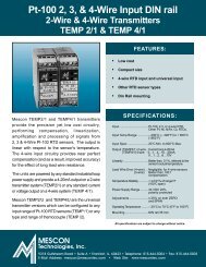
<strong>Pt</strong>-<strong>100</strong> 2, 3, & 4-Wire Input DIN rail<br />
2-Wire & 4-Wire <strong>Transmitters</strong><br />
TEMP 2/1 & TEMP 4/1<br />
FEATURES:<br />
• Low cost<br />
• Compact size<br />
• 4-wire <strong>RTD</strong> input and universal input<br />
• Other <strong>RTD</strong> sensor types<br />
• Din Rail mounting<br />
Mescon TEMP2/1 and TEMP4/1 transmitters<br />
provide the precision yet low cost circuitry,<br />
performing compensation, linearization,<br />
amplification and processing of signals from<br />
2, 3 & 4-Wire <strong>Pt</strong>-<strong>100</strong> <strong>RTD</strong> sensors. The output is<br />
linear with respect to the sensor's temperature.<br />
The 4-wire input circuitry provides near perfect<br />
compensation (and as a result, improved accuracy)<br />
for the effect of long lead wire resistance.<br />
The units are powered by any standard industrial loop<br />
power supply and provide a 4-<strong>20</strong>mA output on a 2-wire<br />
transmitter system (TEMP2/1) or any standard current<br />
or voltage output on a 4-wire system (TEMP 4/1).<br />
Mescon TEMP2/U and TEMP4/U are the universal<br />
transmitter versions which can be configured to any<br />
input range of <strong>Pt</strong>-<strong>100</strong> <strong>RTD</strong> sensors (TEMP /1) or any<br />
type and range of themocouple (TEMP /2).<br />
SPECIFICATIONS:<br />
Input .................................. <strong>Pt</strong>-<strong>100</strong>, 2,3, or 4-wire <strong>RTD</strong>.<br />
Other <strong>Pt</strong>, Ni, NiFe, Cu <strong>RTD</strong>s.<br />
Input Temp Range ............ – <strong>20</strong>0°C (– 328°F) to + 850°C<br />
(1562°F)<br />
Input Span ........................ <strong>20</strong>°C Min. to 800°C Max.<br />
Output (TEMP2/1) 2-wire .. Current loop 4-<strong>20</strong>mA<br />
(TEMP4/1) 4-wire 0…1…4…10…<strong>20</strong>mA,<br />
0…1…2…6…10V<br />
Linearity ............................. Better than 0.1%, referred to the<br />
sensor's actual temperature.<br />
Lead Wire Error (4-wire) ... Negligible, for 4-wire sensors<br />
(3-wire) Better than <strong>100</strong>:1<br />
compensation<br />
<strong>Temperature</strong> Stability ........... < ± 0.01% of range/°F<br />
(<strong>100</strong>°C span)<br />
Power Supply Range ......... 24 VDC <strong>20</strong>%,<br />
polarity protected<br />
Adjustments ...................... ± 25% on both ZERO<br />
and SPAN<br />
Operating <strong>Temperature</strong> ........ – <strong>20</strong>°C to 70°C (0°F to 160°F)<br />
Mounting ........................... DIN rail 35 mm<br />
All specifications are subject to change without notice.<br />
9318 Gulfstream Road • Suite A • Frankfort, IL. 60423 • Telephone: 815-464-5004 • Fax: 815-464-5003<br />
E-Mail Address: mescon@mescontec.com • Web Site: www.mescontec.com
<strong>Pt</strong>-<strong>100</strong> 2, 3, & 4-Wire Input DIN rail<br />
2-Wire & 4-Wire <strong>Transmitters</strong><br />
TEMP 2/1 & TEMP 4/1<br />
Wiring Instructions:<br />
1.Connect the sensor input leads according to the wiring<br />
information drawing. Observe for the proper <strong>RTD</strong> lead type.<br />
2.Connect the output terminals and the power supply<br />
according to the wiring information drawing. Observe for<br />
proper polarity.<br />
Calibration and Adjustments:<br />
It is assumed that the unit undergoing calibration has been<br />
properly ranged at the factory or workshop.<br />
1.Connect an <strong>RTD</strong> simulator to the TEMP X/1 input terminals<br />
according to the wiring diagram.<br />
2.Connect the power supply terminals [1(+) and 2(–)] and<br />
the output terminals to the proper 2-wire (TEMP 2/1) or<br />
4-wire (TEMP 4/1) transmitter connection. Observe for proper<br />
polarity.<br />
3. Set the input to the desired minimum signal and adjust the Zero<br />
pot until the output minimum signal (usually 4.00mA) is set.<br />
4. Set the input to the desired maximum signal and adjust the Zero<br />
pot until the output maximum signal (usually <strong>20</strong>.00mA) is set.<br />
5.Repeat steps 3 & 4 until no further adjustment is needed.<br />
Mounting:<br />
Series TEMP signal conditioners are designed for mounting<br />
on a standard 35 mm DIN rail. Simply place the lower rear rail<br />
groove onto the rail and push the unit into the rail until it snaps<br />
in its place. To dismount, pull the unit in a downward tilt<br />
movement away from the rail.<br />
Dimensions are in inches (mm)<br />
DIN RAIL<br />
Wiring Information<br />
Loop powered<br />
Current<br />
Monitor<br />
+ –<br />
1 2 3 4<br />
2.56<br />
(65)<br />
2.12<br />
(54)<br />
Power<br />
Output<br />
Signal<br />
+ – + –<br />
1 2 3 4<br />
ORDERING INFORMATION<br />
TEMP 4/1 - 3 - (0-<strong>20</strong>0) - °F - (0-10) V<br />
1 2 3 4<br />
SPAN<br />
1 2 3 4<br />
SPAN<br />
TEMP <strong>Model</strong><br />
2/1 = Loop powered<br />
4/1 = Four-wire<br />
Output Units<br />
ZERO<br />
TEMP-2/1<br />
<strong>Pt</strong> - <strong>100</strong><br />
(0 - 350) F<br />
ZERO<br />
TEMP-4/1<br />
<strong>Pt</strong> - <strong>100</strong><br />
(0 - <strong>100</strong>) C<br />
(60)<br />
2.34<br />
No. of wires of <strong>RTD</strong><br />
Output Range<br />
4-<strong>20</strong>mA (2/1),<br />
V or mA (4/1)<br />
(4 - <strong>20</strong>) mA<br />
5 6 7 8<br />
(0 - 10) V<br />
5 6 7 8<br />
Input Range<br />
Input Units (°C or °F)<br />
Please request our ordering and calibration diskette<br />
describing the rest of Mescon's products.<br />
<strong>RTD</strong> Input<br />
0.94<br />
(24)<br />
TEMP 2/1 TEMP 4/1<br />
Distributed By:<br />
Tel: 815-464-5004 • Fax: 815-464-5003<br />
E-Mail Address: mescon@mescontec.com<br />
Web Site: www.mescontec.com<br />
TEMP 2/1 & TEMP 4/1<br />
11.97
Thermocouple Wire Input DIN rail<br />
2-Wire & 4-Wire <strong>Transmitters</strong><br />
TEMP 2/2 & TEMP 4/2<br />
FEATURES:<br />
• User selectable T/C<br />
• User range-able<br />
SPECIFICATIONS:<br />
Input .............................Any Thermocouple type<br />
Mescon TEMP2/2 and TEMP4/2 transmitters<br />
provide the precision, yet low cost circuitry<br />
performing cold junction compensation,<br />
amplification and processing of signals from all<br />
types of thermocouple sensors. The units<br />
provide an output which is linear with respect<br />
to the thermocouple sensor's mV input.<br />
The units are powered by standard industrial<br />
loop powered supply and provide a 4-<strong>20</strong>mA<br />
current loop output on a 2-wire transmitter<br />
system (TEMP2/2) or any standard current or<br />
voltage output on a 4-wire system (TEMP4/2).<br />
Mescon TEMP2/U, and TEMP4/U are the universal<br />
transmitter versions which can be<br />
configured to any type and range of<br />
thermocouple (TEMP /2) and <strong>Pt</strong>-<strong>100</strong> <strong>RTD</strong><br />
sensors (TEMP /1).<br />
Input Span ....................5mV Min.<br />
(<strong>20</strong>mV for rated accuracy)<br />
Linearity .........................0.02% of span<br />
(ref. to mV input)<br />
Burnout Detection .........Upscale, standard<br />
Reference Junction: ......1.0°C max. error over<br />
0-50°C of operating<br />
ambient temp.<br />
Output (TEMP2/2) ........Current loop: 4-<strong>20</strong>mA<br />
(TEMP4/2) 0…1…4…<strong>20</strong>mA,<br />
0…1…4…5…10V<br />
Stability (<strong>20</strong>mV input):......Zero: 1mV/°C or 0,01%<br />
of span/°C<br />
Power Supply Range .....24 VDC ± <strong>20</strong>%,<br />
polarity protected<br />
Adjustments ..................± 25% on both ZERO<br />
and SPAN<br />
Operating <strong>Temperature</strong> ...– <strong>20</strong>°C to 70°C (0°F to 160°F)<br />
Mounting .......................DIN rail, 35 mm<br />
All specifications are subject to change without notice.<br />
9318 Gulfstream Road • Suite A • Frankfort, IL. 60423 • Telephone: 815-464-5004 • Fax: 815-464-5003<br />
E-Mail Address: mescon@mescontec.com • Web Site: www.mescontec.com
Thermocouple Wire Input DIN rail<br />
2-Wire & 4-Wire <strong>Transmitters</strong><br />
TEMP 2/2 & TEMP 4/2<br />
Dimensions are in inches (mm)<br />
DIN RAIL<br />
Wiring Information<br />
Loop powered<br />
Current<br />
Monitor<br />
+ –<br />
1 2 3 4<br />
Power<br />
Output<br />
Signal<br />
+ – + –<br />
1 2 3 4<br />
1 2 3 4<br />
1 2 3 4<br />
SPAN<br />
SPAN<br />
ZERO<br />
TEMP-2/2<br />
TC - J<br />
(0 - 350) F<br />
(4 - <strong>20</strong>) mA<br />
5 6 7 8<br />
ZERO<br />
TEMP-4/2<br />
TC - K<br />
800 - 1<strong>20</strong>0C<br />
(0 - 10) V<br />
5 6 7 8<br />
(60)<br />
2.34<br />
2.56<br />
(65)<br />
2.12<br />
(54)<br />
Wiring Instructions:<br />
1. Connect the sensor input leads according to the wiring information<br />
drawing. Observe for the proper thermocouple lead type.<br />
2. Connect the output terminals and the power supply according to<br />
the wiring information drawing. Observe for proper polarity.<br />
Calibrating and Adjustments:<br />
It is assumed that the unit undergoing calibration has been properly<br />
ranged at the factory workshop.<br />
1. Connect a thermocouple simulator to the TEMP X/2 input terminals<br />
according to wiring diagram.<br />
2. Connect the power supply terminals [1 (+) and 2 (–)] and the output<br />
terminals to the proper 2-wire (TEMP 2/2) or 4-wire (TEMP 4/<br />
2) transmitter connection. Observe for proper polarity. For optimum<br />
performance, allow 15 minutes for temperature gradients<br />
to equalize.<br />
3. Set the input to the desired minimum signal and adjust the Zero<br />
pot until the output minimum signal is set.<br />
4. Set the input maximum to the desired maximum signal and adjust<br />
the Span pot until the output maximum signal is set.<br />
5. Repeat steps 3 and 4 until no further adjustment is needed.<br />
Mounting:<br />
Series TEMP signal conditioners are designed for mounting on a standard<br />
35 mm DIN rail. Simply place the lower rear rail groove onto the<br />
rail and push the unit into the rail until it snaps in its place. To dismount,<br />
pull the unit in a downward tilt movement away from the rail.<br />
– +<br />
THERMOCOUPLE<br />
INPUT<br />
TEMP <strong>Model</strong><br />
2/2 = Loop powered<br />
4/2 = Four-wire<br />
0.94<br />
(24)<br />
TEMP 2/2 TEMP 4/2<br />
ORDERING INFORMATION<br />
TEMP 4/2 - E - (0-<strong>20</strong>0) - °F - (0-10) V<br />
Thermocouple Type<br />
Input Range<br />
Output Units<br />
Output Range<br />
4-<strong>20</strong>mA (2/2),<br />
V or mA (4/2)<br />
Input Units (°C or °F)<br />
Please request our ordering and calibration diskette<br />
describing the rest of Mescon's products.<br />
Distributed By:<br />
Tel: 815-464-5004 • Fax: 815-464-5003<br />
E-Mail Address: mescon@mescontec.com<br />
Web Site: www.mescontec.com<br />
TEMP 2/2 & TEMP 4/2<br />
11.97
Programmable Thermalhead <strong>Transmitters</strong><br />
JUST-PC TECHNOLOGY<br />
Series PTH-400<br />
The Mescon PTH-400 series is a unique PC-programmable 2-wire transmitter family. The units feature a<br />
state of the art micro-processor based design which enables full configuration with Mescon's JUST-PC<br />
Technology using the MESCONfigurator, user friendly configuration software. This combination eliminates<br />
the need for jumpers, calibrators, screw-drivers and hand-held programmers. The PTH-400 is the thermal<br />
head version of an entire family of products. Other JUST-PC<br />
technology instruments are available for field mount, high density DIN<br />
rail and low density DIN rail with display applications.<br />
DC<br />
Power<br />
Supply<br />
–<br />
+<br />
Programming Port<br />
– Monitor +<br />
6<br />
5<br />
Sample loop showing the PTH-400<br />
1.3 "<br />
(33 mm)<br />
4<br />
3 2<br />
1<br />
STANDARD FEATURES:<br />
• Full featured and highly accurate.<br />
• JUST-PC Configuration technology.<br />
No Power Supply needed to program.<br />
.15 "<br />
(4 mm)<br />
4<br />
5<br />
6<br />
1<br />
* Drawings are not to scale<br />
3 4 5<br />
Wiring<br />
6<br />
4-Wire <strong>RTD</strong>/<br />
Resistance<br />
• MESCONfigurator, user friendly<br />
configuration software.<br />
3 2<br />
3 4 5<br />
3-Wire <strong>RTD</strong>/<br />
Resistance<br />
• Full software programmability of<br />
sensor type and input range.<br />
• Linearized 4-<strong>20</strong>mA current loop output<br />
for T/C, <strong>RTD</strong>s, mV, Potentiometers and<br />
Resistance Inputs.<br />
.255 "<br />
(6.5 mm)<br />
1.75 "<br />
(44.5 mm)<br />
4 5<br />
3 4 5<br />
2-Wire <strong>RTD</strong>/<br />
Resistance<br />
Potentiometer<br />
• <strong>20</strong>00 Volts I/O isolation.<br />
• RFI/EMI Protected, marked.<br />
• DIN rail mounting adapter<br />
• Small size thermal head<br />
• Custom Linearization in minutes<br />
.725 "<br />
(18.5 mm)<br />
S/N<br />
MESCON<br />
Z<br />
S<br />
4 5<br />
+ –<br />
4 5<br />
+ –<br />
DC mV<br />
T/C<br />
9318 Gulfstream Road • Suite A • Frankfort, IL. 60423 • Telephone: 815-464-5004 • Fax: 815-464-5003<br />
E-Mail Address: mescon@mescontec.com • Web Site: www.mescontec.com
Programmable Thermalhead <strong>Transmitters</strong><br />
JUST-PC TECHNOLOGY<br />
Series PTH-400<br />
Configuration: All Input types and range parameters<br />
are easily configurable with Mescon's user friendly<br />
JUST-PC Technology, which requires no power<br />
supply for configuration using the PA-400 programming<br />
adapter and the MESCONfigurator Graphic User<br />
Interface software under Windows ® operating systems<br />
through the PC's RS232 serial port.<br />
SPECIFICATIONS<br />
INPUT CONFIGURATIONS<br />
Thermocouples ........... Most standard types and all special<br />
types using customer defined tables<br />
and polynomials.<br />
<strong>RTD</strong> ............................ 2, 3, and 4 wire, <strong>Pt</strong>-<strong>100</strong>, Ni-110 and<br />
other <strong>RTD</strong>s. Includes Callandar-<br />
Van-Dusen adaptation and custom<br />
sensors linearization with user<br />
defined tables and polynomials.<br />
Potentiometers ............ to <strong>20</strong> Ký<br />
Resistance .................. to 400 ý<br />
DC-mV ........................ –10 to <strong>100</strong> mV<br />
GENERAL SPECIFICATIONS<br />
Minimum Range .......... 2 mV. Limited mostly by input signal<br />
quality.<br />
Output ......................... 4-<strong>20</strong>mA isolated loop powered.<br />
Supply Voltage ............ 9-40 VDC (@ no load). Reverse<br />
polarity protected.<br />
Maximum Load ........... R max = (Vsupply - 9V) ÷ <strong>20</strong>mA<br />
Operating<br />
<strong>Temperature</strong> ................ –40°C to +85°C<br />
Storage<br />
<strong>Temperature</strong> ................ –55°C to +125°C<br />
Humidity ...................... 0-95% RH, non-condensing.<br />
Response Time ........... 0.3 seconds, to 90% of input.<br />
(> 3 updates per second).<br />
GENERAL SPECIFICATIONS (continued)<br />
Damping Factors ........ Programmable 0.0 to 64.0 seconds, to<br />
0 - 1<strong>20</strong>% of input range, using<br />
MESCONfigurator software interface.<br />
Stability ....................... Better than ±0.1% of span for 12<br />
months.<br />
I/O Isolation ....................... <strong>20</strong>00 VDC or peak AC.<br />
RFI Protection ................... < 1% effect of span at <strong>20</strong>-<strong>100</strong>0<br />
MHz and at field strength of<br />
<strong>20</strong>V/m. marked.<br />
PERFORMANCE SPECIFICATIONS<br />
Output Resolution ............. 0.015% of span (2.5µA).<br />
Output (D/A) Linearity .......Better than 0.02% of output span.<br />
Sensor<br />
Linearization ...................... Better than 0.1°C for <strong>RTD</strong>s.<br />
Better than 0.2°C for T/C.<br />
Cold Junction<br />
Compensation ................... Automatic to within ±0.7°C<br />
for all T/C.<br />
<strong>Temperature</strong> Stability ........ 0.015%/°C combined ZERO<br />
and SPAN.<br />
Supply Voltage Effect: .......
Thermistor Input - World's first<br />
Programmable Thermalhead Transmitter<br />
<strong>Model</strong> PTH-440 with JUST-PC TECHNOLOGY<br />
The Mescon PTH-440 is a unique PC-programmable 2-wire transmitter family. The PTH-440 feature stateof-<br />
the-art microprocessor based design which enables full configuration with Mescon's JUST-PC Technology<br />
using the user-friendly MESCONfigurator Graphic User Interface. This combination eliminates the need<br />
for jumpers, calibrators, screw-drivers and hand-held programmers. The PTH-440 is the thermal head version<br />
of a comprehensive family of products. Other JUST-PC technology<br />
instruments are available for field mount, high density DIN rail and<br />
low density DIN rail with display applications.<br />
DC<br />
Power<br />
Supply<br />
–<br />
+<br />
Programming Port<br />
– Monitor +<br />
6<br />
5<br />
Sample loop showing the PTH-440<br />
1.3 "<br />
(33 mm)<br />
4<br />
3 2<br />
1<br />
STANDARD FEATURES:<br />
5<br />
6<br />
* Drawings not to scale<br />
• Fully Linearized output with respect to<br />
temperature.<br />
• Custom Linearization for virtually all<br />
thermitor types and makes.<br />
• 0.01KΩ to <strong>20</strong>00KΩ input range.<br />
.15 "<br />
(4 mm)<br />
4<br />
3 2<br />
1<br />
Wiring<br />
Low-resistance NTCthermistor<br />
(10 ... 25000)Ω range<br />
• High Resolution (to 0.01°C) and staility.<br />
• Full featured and highly accurate.<br />
• JUST-PC Configuration technology.<br />
• MESCONfigurator, friendly Graphic<br />
User Interface software.<br />
.255 "<br />
(6.5 mm)<br />
1.75 "<br />
(44.5 mm)<br />
High-resistance NTCthermistor<br />
(0.5 ... 4000)KΩ range<br />
• <strong>20</strong>00 Volts I/O isolation.<br />
• RFI/EMI Protected, marked.<br />
• DIN rail mounting adapter<br />
• Small size thermal head<br />
.725 "<br />
(18.5 mm)<br />
S/N<br />
MESCON<br />
Z<br />
S<br />
9318 Gulfstream Road • Suite A • Frankfort, IL. 60423 • Telephone: 815-464-5004 • Fax: 815-464-5003<br />
E-Mail Address: mescon@mescontec.com • Web Site: www.mescontec.com
Thermistor Input - World's first<br />
Programmable Thermalhead Transmitter<br />
<strong>Model</strong> PTH-440 with JUST-PC TECHNOLOGY<br />
Configuration: All thermistor types and range<br />
parameters are easily configurable with Mescon's user<br />
friendly JUST-PC Technology, which requires no<br />
power supply for configuration. Use the PA-400<br />
programming adapter and the MESCONfigurator<br />
Graphic User Interface software under Windows ®<br />
operating systems and the PC's RS232 serial port.<br />
SPECIFICATIONS<br />
INPUT CONFIGURATIONS<br />
Thermistors ................. Most standard types and makes,<br />
and all special types with userdefined-tables<br />
and polynomials.<br />
Linearization for YSI thermistors<br />
is standard, others available upon<br />
request. Optional - custom types,<br />
ranges and resolutions.<br />
Resistance range ....... From 0.02KΩ to <strong>20</strong>00KΩ<br />
in two input sections.<br />
Min/Max span ............. 5°C min., 150°C max.<br />
Output ......................... 4-<strong>20</strong>mA isolated loop powered.<br />
Supply Voltage ............ 9-40 VDC (@ no load). Reverse<br />
polarity protected.<br />
Maximum Load ........... R max = (Vsupply - 9V) ÷ <strong>20</strong>mA<br />
Operating<br />
<strong>Temperature</strong> ............... –40°C to +85°C<br />
Storage<br />
<strong>Temperature</strong> ............... –55°C to +125°C<br />
Humidity ...................... 0-95% RH, non-condensing.<br />
Response Time .......... 0.3 seconds, to 90% of input.<br />
(> 3 updates per second).<br />
GENERAL SPECIFICATIONS (continued)<br />
Damping Factors ........ Programmable 0.0 to 64.0 seconds, to<br />
0 - 1<strong>20</strong>% of input range, using<br />
MESCONfigurator software interface.<br />
Stability ....................... Better than ±0.1% of span for 12<br />
months.<br />
I/O Isolation ....................... <strong>20</strong>00 VDC or peak AC.<br />
RFI Protection ................... < 1% effect of span at <strong>20</strong>-<strong>100</strong>0<br />
MHz and at field strength of <strong>20</strong>V/<br />
m. marked.<br />
PERFORMANCE SPECIFICATIONS<br />
Output Resolution ............. 0.015% of span (2.5µA).<br />
Output (D/A) Linearity ....... Better than 0.02% of output span.<br />
Sensor<br />
Linearization* .................... Better than 0.1°C most<br />
thermistors types and ranges.<br />
<strong>Temperature</strong> Stability ........0.01%/°C combined ZERO and<br />
SPAN.<br />
Supply Voltage Effect: .......
Programmable High Density Din Rail <strong>Transmitters</strong><br />
JUST-PC TECHNOLOGY<br />
Series PDT-400<br />
The Mescon PDT-400 series is a unique PC-programmable 2-wire transmitter family.<br />
The units feature a state of the art micro-processor based design which enables<br />
complete configuration with Mescon's JUST-PC Technology using the<br />
MESCONfigurator, user friendly configuration software. This eliminates the need<br />
for power supplies, calibrators, screw-drivers, wires, jumpers and hand-held<br />
programmers. The PDT-400 is the DIN rail mounted version of an entire family of<br />
products. Other Just-PC technology instruments are available for thermal-head,<br />
field-mount, high density Din rail and Digital display applications.<br />
Sample loop showing the PDT-410<br />
Monitor<br />
–<br />
+<br />
Output/2<br />
(optional)<br />
STANDARD<br />
FEATURES:<br />
* Drawings are not to scale<br />
Power<br />
Supply<br />
+<br />
–<br />
1 2<br />
+ –<br />
5 6<br />
• JUST-PC Configuration<br />
Technology. No power supply<br />
needed for programming<br />
• MesConfigurator user friendly<br />
software<br />
(89.5 mm)<br />
3.53 in<br />
(60.2 mm)<br />
2.36 in<br />
(90.4 mm)<br />
3.55 in<br />
PDT<br />
400<br />
7<br />
3<br />
PDT<br />
410<br />
8<br />
4<br />
• Full software programmability<br />
of sensor type and input range<br />
• Linearized 4-<strong>20</strong>mA output for T/<br />
C, <strong>RTD</strong>s, mV, Potentiometers<br />
and Resistance Inputs<br />
• <strong>20</strong>00 Volts I/O isolation<br />
• Ultra High Density DIN rail<br />
mounting<br />
TC<br />
& DC mV<br />
7 8<br />
4.03 in<br />
(102.5 mm)<br />
2-Wire <strong>RTD</strong><br />
Resistance<br />
7 8<br />
0.5 in<br />
(13.0 mm)<br />
PDT 400 Wiring<br />
3-Wire <strong>RTD</strong><br />
Resistance<br />
7 8<br />
4-Wire <strong>RTD</strong><br />
Resistance<br />
7 8<br />
DC-mV<br />
DC-Volts<br />
DC-mA<br />
7 3 4 8<br />
7 8<br />
+<br />
+ –<br />
3<br />
+<br />
Potentiometer<br />
7 8<br />
4<br />
8<br />
–<br />
8<br />
–<br />
• Custom Linearization in minutes<br />
• Optional dual output capability<br />
3 4<br />
3 4<br />
3 4<br />
3 4<br />
3 4<br />
• RFI/EMI Protected,<br />
marked<br />
+ –<br />
9318 Gulfstream Road • Suite A • Frankfort, IL. 60423 • Telephone: 815-464-5004 • Fax: 815-464-5003<br />
E-Mail Address: mescon@mescontec.com • Web Site: www.mescontec.com
Programmable High Density Din Rail <strong>Transmitters</strong><br />
JUST-PC TECHNOLOGY<br />
Series PDT-400<br />
Configuration: All Input types and range parameters<br />
are easily configurable with Mescon's user friendly<br />
JUST-PC Technology, which requires no power<br />
supply for configuration using the PA-400 programming<br />
adapter and the MESCONfigurator Graphic User<br />
Interface software under Windows ® operating systems<br />
through the PC's RS232 serial port.<br />
SPECIFICATIONS:<br />
INPUT CONFIGURATIONS<br />
Thermocouples ........... Most standard types and all special<br />
types using customer defined tables<br />
and polynomials. (PDT-400)<br />
<strong>RTD</strong> ............................ 2, 3, and 4 wire, <strong>Pt</strong>-<strong>100</strong>, Callandar-Van-<br />
Dusen adaptation, User defined<br />
sensor types available. (PDT-400)<br />
Potentiometers ........... to <strong>20</strong> Ký (PDT-400)<br />
Resistance .................. to 400 ý (PDT-400)<br />
DC-mV ........................ -10 to <strong>100</strong> mV (PDT-400)<br />
DC-mV ........................ -30 to 300 mV (PDT-410)<br />
DC-Volts ..................... Up to 10 Volts (PDT-410)<br />
DC-mA ........................ Up to 50 mA (PDT-410)<br />
GENERAL SPECIFICATIONS<br />
Minimum Range ......... 2 mV. Limited mostly by input signal<br />
quality.<br />
Output ......................... 4-<strong>20</strong>mA isolated loop powered.<br />
Supply Voltage ............ 9-40 VDC (@ no load). Reverse<br />
polarity protected.<br />
Maximum Load ........... R max = (V supply - 9V) ÷ <strong>20</strong>mA<br />
Operating<br />
<strong>Temperature</strong> ............... –40°C to +85°C<br />
Storage<br />
<strong>Temperature</strong> ............... –55°C to +125°C<br />
Humidity...................... 0-95% RH, non-condensing.<br />
Response Time .......... 0.3 seconds, to 90% of input.<br />
(> 3 updates per second).<br />
GENERAL SPECIFICATIONS (continued)<br />
Damping Factors ............... Programmable 0.0 to 64.0<br />
seconds, to 0 - 1<strong>20</strong>% of input<br />
range, using MESCONfigurator<br />
software interface.<br />
Stability .............................. Better than ±0.1% of span for<br />
12 months.<br />
I/O Isolation ....................... <strong>20</strong>00 VDC or peak AC.<br />
RFI Protection ................... < 1% effect of span at <strong>20</strong>-<strong>100</strong>0<br />
MHz and at field strength of<br />
<strong>20</strong>V/m. marked.<br />
PERFORMANCE SPECIFICATIONS<br />
Output Resolution ............. 0.015% of span (2.5µA).<br />
Output (D/A) Linearity ....... Better than 0.02% of output span.<br />
Sensor<br />
Linearization ......................Better than 0.1°C for <strong>RTD</strong>s.<br />
Better than 0.2°C for T/C.<br />
Cold Junction<br />
Compensation ................... Automatic to within ±0.5°C<br />
for all T/C.<br />
<strong>Temperature</strong> Stability ........ 0.012%/°C combined ZERO<br />
and SPAN.<br />
Supply Voltage Effect: ....... < ±0.002% per volt<br />
Calibration ......................... Automatic. Unit includes all of<br />
the calibration parameters. It<br />
performs periodic “ZERO”,<br />
“SPAN”, self-test, and auto<br />
calibration.<br />
Input Linearity ....................Better than 0.01% of span (mV input).<br />
All specifications are subject to change without notice.<br />
PA - 400<br />
ORDERING INFORMATION<br />
PDT - 4 X X<br />
PDT 4 X X<br />
0 = Temp<br />
1 = DC - mA - mV - V<br />
3 = Frequency<br />
4 = Thermistor<br />
0 = Single Output<br />
2 = Dual Output<br />
Programming Adapter (RS232)<br />
Windows ® is a registered trademark of Microsoft Corporation.<br />
Distributed By:<br />
Tel: 815-464-5004 • Fax: 815-464-5003<br />
E-Mail Address: mescon@mescontec.com<br />
Web Site: www.mescontec.com<br />
PDT - 400<br />
4.98
Programmable Field Mounted <strong>Transmitters</strong><br />
JUST-PC TECHNOLOGY<br />
Series PFT-400<br />
The Mescon PFT-400 series is a unique PC-programmable 2-wire<br />
transmitter family. The units feature a state of the art micro-processor<br />
based design which enables full configuration with Mescon's JUST-PC<br />
Technology using the MESCONfigurator, user friendly configuration<br />
software. This combination eliminates the need for jumpers, calibrators,<br />
screw-drivers and hand-held programmers. The PFT-400 is the field<br />
mounted version of an entire family of products. Other JUST-PC<br />
technology instruments are available for thermal-head, high density DIN<br />
rail and low density DIN rail with display applications.<br />
Programming Port<br />
Sample loop showing<br />
1<br />
PFT<br />
2 3 4<br />
– +<br />
5 6<br />
+ – Output<br />
– + Loop<br />
+<br />
LOAD (R L )<br />
DC Supply<br />
–<br />
the PFT-400<br />
+<br />
–<br />
4<br />
3<br />
-2<br />
1<br />
PFT<br />
TC<br />
& DC mV<br />
1<br />
2 3 4<br />
–<br />
5 6 +<br />
2.75 in<br />
(70 mm)<br />
3.04 in<br />
(77 mm)<br />
2-Wire <strong>RTD</strong><br />
Resistance<br />
4<br />
3<br />
2<br />
1<br />
Programming Port<br />
4<br />
3<br />
2<br />
1<br />
2.75 in<br />
(70 mm)<br />
3-Wire <strong>RTD</strong><br />
Resistance<br />
Wiring<br />
4-Wire <strong>RTD</strong><br />
Resistance<br />
+ 4<br />
3<br />
2<br />
1<br />
* Drawings are not to scale<br />
Potentiometer<br />
4<br />
3<br />
2<br />
1<br />
4<br />
V +<br />
3<br />
mV +<br />
2<br />
1<br />
mA +<br />
1.36 in<br />
(35 mm)<br />
1.87 in<br />
(48 mm)<br />
DC Inputs<br />
(PFT 410 Only)<br />
mV term 3 +<br />
mA term 1 +<br />
V term 4 +<br />
term 2<br />
always<br />
–<br />
STANDARD<br />
FEATURES:<br />
• Full featured and highly accurate.<br />
• JUST-PC Configuration technology.<br />
No Power Supply needed to program.<br />
• MESCONfigurator, user friendly<br />
configuration software.<br />
• Full software programmability of<br />
sensor type and input range.<br />
• Linearized 4-<strong>20</strong>mA current loop output<br />
for T/C, <strong>RTD</strong>s, mV, Potentiometers and<br />
Resistance Inputs.<br />
• Custom Linearization in minutes.<br />
• <strong>100</strong>0 Volts I/O isolation.<br />
• RFI/EMI Protected,<br />
marked.<br />
9318 Gulfstream Road • Suite A • Frankfort, IL. 60423 • Telephone: 815-464-5004 • Fax: 815-464-5003<br />
E-Mail Address: mescon@mescontec.com • Web Site: www.mescontec.com
Programmable Field Mounted <strong>Transmitters</strong><br />
JUST-PC TECHNOLOGY<br />
Series PFT-400<br />
Configuration: All Input types and range parameters<br />
are easily configurable with Mescon's user friendly<br />
JUST-PC Technology, which requires no power<br />
supply for configuration using the A-400 P programming<br />
adapter and the MESCONfigurator Graphic User<br />
®<br />
Interface software under Windows operating systems<br />
through the PC's RS232 serial port.<br />
SPECIFICATIONS:<br />
INPUT CONFIGURATIONS<br />
Thermocouples ...........Most standard types and all special<br />
types using customer defined tables<br />
and polynomials. (PFT-400)<br />
<strong>RTD</strong> ............................ 2, 3, and 4 wire, <strong>Pt</strong>-<strong>100</strong>, Callandar-Van-<br />
Dusen adaptation, User defined<br />
sensor types available. (PFT-400)<br />
Potentiometers ........... to <strong>20</strong> Ký (PFT-400)<br />
Resistance .................. to 400 ý (PFT-400)<br />
DC-mV ........................ -10 to <strong>100</strong> mV (PFT-400)<br />
DC-mV ........................ -30 to 300 mV (PFT-410)<br />
DC-Volts ..................... Up to 10 Volts (PFT-410)<br />
DC-mA ........................ Up to 50 mA (PFT-410)<br />
GENERAL SPECIFICATIONS<br />
Minimum Range ......... 2 mV. Limited mostly by input signal<br />
quality.<br />
Output ......................... 4-<strong>20</strong>mA isolated loop powered.<br />
Supply Voltage ............ 9-40 VDC (@ no load). Reverse<br />
polarity protected.<br />
Maximum Load ........... R max = (V supply - 9V) ÷ <strong>20</strong>mA<br />
Operating<br />
<strong>Temperature</strong> ............... –40°C to +85°C<br />
Storage<br />
<strong>Temperature</strong> ............... –55°C to +125°C<br />
Humidity...................... 0-95% RH, non-condensing.<br />
Response Time .......... 0.3 seconds, to 90% of input.<br />
(> 3 updates per second).<br />
Damping Factors ........Programmable 0.0 to 64.0 seconds, to<br />
0 - 1<strong>20</strong>% of input range, using<br />
MESCONfigurator software interface.<br />
GENERAL SPECIFICATIONS (continued)<br />
Stability .............................. Better than ±0.1% of span for<br />
12 months.<br />
I/O Isolation ....................... <strong>100</strong>0 VDC or peak AC.<br />
RFI Protection ................... < 0.5% effect of span at <strong>20</strong>-<br />
<strong>100</strong>0 MHz and at field strength<br />
of <strong>20</strong>V/m. marked.<br />
PERFORMANCE SPECIFICATIONS<br />
Output Resolution ............. 0.015% of span (2.5µA).<br />
Output (D/A) Linearity ....... Better than 0.02% of output span.<br />
Sensor<br />
Linearization ......................Better than 0.1°C for <strong>RTD</strong>s.<br />
Better than 0.2°C for T/C.<br />
Cold Junction<br />
Compensation ...................Automatic to within ±0.5°C<br />
for all T/C.<br />
<strong>Temperature</strong> Stability ........ 0.012%/°C combined ZERO<br />
and SPAN.<br />
Supply Voltage Effect: .......
Programmable Din Rail <strong>Transmitters</strong><br />
JUST-PC TECHNOLOGY<br />
Series P-<strong>20</strong><br />
The Meson P-<strong>20</strong> series is a unique PC-Programmable 2-wire transmitter family using Mescon's Just -PC technology.<br />
The units feature state of the art micro-processor design which enables complete input configuration using the<br />
MesconFigurator, user-friendly configuration software and Graphic user Interface. The need for power supply,<br />
calibrators, jumpers, screw-drivers, wires and hand-held programmers has been eliminated. The P-<strong>20</strong> also features<br />
an optional LCD digital display for continuous indication of the measured process variable. Other Just-PC technology<br />
instruments are available for thermal-head, field mounted and high density DIN rail applications.<br />
1.77 in<br />
(45.0 mm)<br />
2.07 in<br />
( 53.0 mm )<br />
Programming<br />
Port<br />
INPUT<br />
1 2 3 4<br />
2.91 in<br />
(74.0 mm)<br />
S/N<br />
5 6 7 8 9101112 TST<br />
+ -<br />
OUTPUT<br />
WIRING LABEL<br />
Optional<br />
Display<br />
1 2 3 4<br />
Sample loop<br />
showing the P-<strong>20</strong><br />
S/N<br />
P-<strong>20</strong> Wiring<br />
5 6 7 8 9101112<br />
+ -<br />
TST<br />
Potentiometer 2 3 4<br />
2-wire <strong>RTD</strong> / Resistance 2 4<br />
3-wire <strong>RTD</strong> / Resistance 2 3 4<br />
4-wire <strong>RTD</strong> / Resistance 1 2 3 4<br />
T.C.<br />
DC-mV<br />
–<br />
+<br />
2 3<br />
–<br />
+<br />
2 3<br />
1 2 3 4<br />
Monitor<br />
+ –<br />
–<br />
+<br />
DC<br />
Power-Supply<br />
* Drawings are not to scale<br />
P-21 Wiring<br />
+ –<br />
1 2<br />
– +<br />
2<br />
– +<br />
DC-mA<br />
DC-Volts<br />
DC-mV<br />
2 3<br />
1 2 3 4<br />
4<br />
STANDARD FEATURES:<br />
• JUST-PC Configuration Technology.<br />
No power supply needed for programming<br />
• MesConfigurator user friendly software<br />
• Full software programmability of sensor type<br />
and input range<br />
• Linearized 4-<strong>20</strong>mA output for T/C, <strong>RTD</strong>s, mV,<br />
Potentiometers and Resistance Inputs<br />
• <strong>20</strong>00 Volts I/O isolation<br />
• Custom Linearization in minutes<br />
• RFI/EMI Protected,<br />
marked<br />
9318 Gulfstream Road • Suite A • Frankfort, IL. 60423 • Telephone: 815-464-5004 • Fax: 815-464-5003<br />
E-Mail Address: mescon@mescontec.com • Web Site: www.mescontec.com
Programmable Din Rail <strong>Transmitters</strong><br />
JUST-PC TECHNOLOGY<br />
Series P-<strong>20</strong><br />
Configuration: All Input types and range parameters<br />
are easily configurable with Mescon's user friendly<br />
JUST-PC Technology, which requires no power<br />
supply for configuration using the PA-400 programming<br />
adapter and the MESCONfigurator Graphic User<br />
Interface software under Windows ® operating systems<br />
through the PC's RS232 serial port.<br />
SPECIFICATIONS:<br />
INPUT CONFIGURATIONS<br />
Thermocouples ........... Most standard types and all special<br />
types using customer defined tables<br />
and polynomials. (P-<strong>20</strong>)<br />
<strong>RTD</strong> ............................ 2, 3, and 4 wire, <strong>Pt</strong>-<strong>100</strong>, Callandar-Van-<br />
Dusen adaptation, User defined<br />
sensor types available. (P-<strong>20</strong>)<br />
Potentiometers ........... to <strong>20</strong> Ký (P-<strong>20</strong>)<br />
Resistance .................. to 400 ý (P-<strong>20</strong>)<br />
DC-mV ........................ -10 to <strong>100</strong> mV (P-<strong>20</strong>)<br />
DC-mV ........................ -30 to 300 mV (P-21)<br />
DC-Volts ..................... Up to 10 Volts (P-21)<br />
DC-mA ........................ Up to 50 mA (P-21)<br />
GENERAL SPECIFICATIONS<br />
Minimum Range ......... 2 mV. Limited mostly by input signal<br />
quality.<br />
Output ......................... 4-<strong>20</strong>mA isolated loop powered.<br />
Supply Voltage ............ 9-40 VDC (@ no load). Reverse<br />
polarity protected. (12-40V with<br />
optional display)<br />
Maximum Load ........... R max = (V supply - 9V) ÷ <strong>20</strong>mA<br />
Operating<br />
<strong>Temperature</strong> ............... –40°C to +85°C<br />
Storage<br />
<strong>Temperature</strong> ............... –55°C to +125°C<br />
Humidity...................... 0-95% RH, non-condensing.<br />
Response Time .......... 0.3 seconds, to 90% of input.<br />
(> 3 updates per second).<br />
Range ......................... 0-<strong>100</strong>%<br />
GENERAL SPECIFICATIONS (continued)<br />
Damping Factors ............... Programmable 0.0 to 64.0<br />
seconds, to 0 - 1<strong>20</strong>% of input<br />
range, using MESCONfigurator<br />
software interface.<br />
Stability .............................. Better than ±0.1% of span for<br />
12 months.<br />
I/O Isolation ....................... <strong>20</strong>00 VDC or peak AC.<br />
RFI Protection ................... < 1% effect of span at <strong>20</strong>-<strong>100</strong>0<br />
MHz and at field strength of<br />
<strong>20</strong>V/m. marked.<br />
Optional Display ................ 3 1/2 digits, LCD, Back-lit<br />
PERFORMANCE SPECIFICATIONS<br />
Output Resolution ............. 0.015% of span (2.5µA).<br />
Output (D/A) Linearity .......Better than 0.02% of output span.<br />
Sensor<br />
Linearization ...................... Better than 0.1°C for <strong>RTD</strong>s.<br />
Better than 0.2°C for T/C.<br />
Cold Junction<br />
Compensation ................... Automatic to within ±0.5°C<br />
for all T/C.<br />
<strong>Temperature</strong> Stability ........ 0.012%/°C combined ZERO<br />
and SPAN.<br />
Supply Voltage Effect: ....... < ±0.002% per volt<br />
Calibration ......................... Automatic. Unit includes all of<br />
the calibration parameters. It<br />
performs periodic “ZERO”,<br />
“SPAN”, self-test, and auto<br />
calibration.<br />
Input Linearity .................... Better than 0.01% of span (mV input).<br />
All specifications are subject to change without notice.<br />
ORDERING INFORMATION<br />
P - 2 X X<br />
P- 2X X<br />
0 = Temp<br />
Optional<br />
1 = DC - mA - mV - V<br />
Display<br />
3 = Frequency<br />
4 = Thermistor<br />
PA - 400 Programming Adapter (RS232)<br />
Windows ® is a registered trademark of Microsoft Corporation.<br />
Distributed By:<br />
Tel: 815-464-5004 • Fax: 815-464-5003<br />
E-Mail Address: mescon@mescontec.com<br />
Web Site: www.mescontec.com<br />
P-<strong>20</strong><br />
4.98
SMART ISOLATED 2-WIRE TRANSMITTER<br />
Signal Transmission - The Smart Way<br />
SeriesSST-<strong>20</strong>0<br />
S TANDARD FEAT U R E S :<br />
• Universal input capability in 3 variations to<br />
accept most of today's process parameters:<br />
Thermocouples, <strong>RTD</strong>'s, DCmV, Potentiometers,<br />
Resistance sensors, DCmA, DCV, AC Amps,<br />
Frequency and Pulse.<br />
• Fully software driven. All input parameters are<br />
programmable. An external hand-held programmer<br />
or an integral transmitter mounted programmer (both<br />
optional) enables on-site calibration and indication of<br />
process parameters.<br />
• Heavy-duty all metal case construction and<br />
carefully designed input and output circuitry ensures<br />
a high degree of protection from adverse<br />
environmental conditions to maximize RFI/EMI<br />
immunity.<br />
• High precision linearization for Thermocouple<br />
and <strong>RTD</strong> sensor inputs, Inverse output capability,<br />
variable input signal damping, Sensor breakdown<br />
indication, full display scaling capability, auto-zero<br />
input, and more.<br />
• Advanced signal processing t e c h n o l o g y<br />
provides features not commonly found among other<br />
smart transmitters such as: Square-root function,<br />
Loop-simulation, and optional capabilities for Dual<br />
Inputs and Mathematical manipulations.<br />
• The SST is available for surface or DIN r a i l<br />
mounting, and can be furnished in NEMA 4 and<br />
Explosion-Proof enclosures.<br />
The SST-<strong>20</strong>0 is one of the most advanced, userfriendly<br />
and powerful, smart 2-wire transmitters.<br />
The state of the art micro-processor design<br />
combines simplicity, precision and ruggedness to<br />
produce a unique product suitable for industrial<br />
measurements in countless applications.<br />
OPTIONAL FEAT U R E S :<br />
• LCD Display.<br />
• Programmers, hand-held or integrally<br />
mounted, both with LCD display.<br />
• Digital communication for interfacing with<br />
PC, PLC, and remote programmers<br />
(HART ® Protocol).<br />
MESCON<br />
Technologies, Inc.<br />
9318 Gulfstream Road, Suite A, Frankfort, IL 60423<br />
Phone: 815-464-5004<br />
Fax: 815-464-5003<br />
E-Mail: mescon@mescontec.com<br />
Web: www.mescontec.com<br />
HART®-Smart Communications Protocol Specification is a trademark of Rosemount, Inc.
SMART ISOLATED 2-WIRE TRANSMITTER<br />
Signal Transmission - The Smart Way<br />
SeriesSST-<strong>20</strong>0<br />
GENERAL SPECIFICATIONS<br />
INPUTS:<br />
Thermocouples (types E, J, K, T, R, S, N, B, C)<br />
<strong>RTD</strong> 2, 3, and 4-wire <strong>Pt</strong>-<strong>100</strong>, (DIN & NIST curves) <strong>Pt</strong>-<strong>20</strong>0,<br />
Ni-<strong>100</strong>, Cu-10 and other <strong>RTD</strong>s.<br />
DC mV ±1<strong>20</strong>.00mV input span.<br />
Potentiometers <strong>100</strong>Ω to <strong>20</strong>KΩ.<br />
Resistance 2, 3, and 4-wire 0 to 600Ω.<br />
Optional:DCmA, DCV.<br />
Optional:AC-Volts, AC-Amps, Frequency/Pulse.<br />
MINIMUM RANGE:<br />
None. limited only by signal quality.<br />
DIGITAL RESOLUTION:<br />
>17 Bits.<br />
OUTPUTS:<br />
4-<strong>20</strong>mA isolated analog current loop, standard.<br />
Optional: Digital communication, HART ® Protocol.<br />
DISPLAY:<br />
8x1 Character LCD indicator for programming and display<br />
of input and output parameters and status.<br />
SUPPLY:<br />
12-45 VDC (@ no load). Reverse polarity protected.<br />
OPERATING CONDITIONS:<br />
-<strong>20</strong>°C TO +70°C. 0-95% RH, non-condensing.<br />
STORAGE TEMPERATURE:<br />
-55°C to +125°C<br />
TURN-ON TIME:<br />
Within 4 seconds to rated response.<br />
RESPONSE TIME:<br />
0.5 seconds to 99% of reading (2 updates per second).<br />
DAMPING FACTOR:<br />
Programmable 0.0 to 32.0 seconds.<br />
LONG TERM STABILITY:<br />
Better than ±0.1% of span for 6 months.<br />
ISOLATION:<br />
800 VDC or peak AC<br />
RFI/EMI IMMUNITY:<br />
Tested per SAMA PMC 33.1C from <strong>20</strong> to <strong>100</strong>0 MHz and<br />
for field strength up to 30 V/m.<br />
C.M.R.R.:<br />
>1<strong>20</strong>db DC to 60 Hz<br />
ENCLOSURE:<br />
Extruded, anodized Aluminum.<br />
DIMENSIONS:<br />
3.00" x 2.44" x 2.46" (without display)<br />
3.00" x 2.44" x 3.00" (with display)<br />
(Hockey-puck housing. Suitable for mounting inside<br />
3.5" diameter explosion-proof enclosures.<br />
PERFORMANCE SPECIFICATIONS<br />
ANALOG OUTPUT RESOLUTION:<br />
0.025% of span (±4 µA)<br />
ANALOG OUTPUT (D/A) LINEARITY:<br />
±0.025% of span.<br />
DIGITAL SENSOR LINEARIZATION:<br />
Series SST-270<br />
Smart, Isolated, loop powered<br />
Flow Rate transmitters<br />
STANDARD FEATURES<br />
SST-270K<br />
•<br />
User Friendly - fully prompted<br />
programming<br />
• Heavy duty all metal construction<br />
In Ex-proof enclosure<br />
The SST-270 is a smart, state of the art,<br />
µP based, frequency/Pulse input, Flow-<br />
Rate 2-wire transmitter. It incorporates<br />
advanced circuitry and firmware including<br />
user defined 16-point linearization capability,<br />
which enables it to provide a high<br />
degree of precision performance and<br />
user flexibility in industrial flow measurement<br />
applictions.<br />
The SST-270 is a member of Mescon’s<br />
advanced user friendly and high-precision,<br />
line of industrial, process measurements<br />
line of 2-wire transmitters.<br />
Custom versions are available for special<br />
purpose and OEM applications<br />
MESCON<br />
Technologies, Inc.<br />
•<br />
•<br />
•<br />
•<br />
•<br />
•<br />
•<br />
•<br />
•<br />
•<br />
•<br />
•<br />
16 point K-factor linearization<br />
Direct programming in flow units<br />
Advanced digital signal filtering<br />
Automatic flow units conversion<br />
High input range sensitivity<br />
Loop Powered, 4-<strong>20</strong>mA output<br />
User defined input trimming<br />
Flush, DIN rails or Ex-proof mounting<br />
OPTIONAL FEATURES<br />
8-character Display/programmer for<br />
direct reading of Flow-Rate and units<br />
(K-option).<br />
Digital communications HART protocol<br />
providing universal HART commands<br />
(H-option)<br />
Hand Held display/programmer for on-site<br />
programming (STP-<strong>20</strong>0)<br />
Magnetically activated keys for programming<br />
thru Ex-proof enclosure window (R-option)<br />
9502 Gulfstream Road • Suite A • Frankfort, IL. 60423 • Telephone: 815-464-5004 • Fax: 815-464-5003<br />
E-Mail Address: mescon@mescontec.com • Web Site: www.mescontec.com
Series SST-270<br />
Smart, Isolated, loop powered<br />
Flow Rate transmitters<br />
SPECIFICATIONS:<br />
Inputs:...........................Frequency/Pulse. Magnetic pick-up, opto<br />
or Hall effect sensors.<br />
Input Range:..................................................0.5 to 4000 Hz<br />
Trigger Sensitivity:.....................................................30 mV<br />
Over Voltage Protection:......................................300 VDC<br />
Digital Resolution:................................................>17 bits.<br />
Outputs:..................4-<strong>20</strong>mA isolated current loop, standard.<br />
Optional: HART R Protocol communiction<br />
Maximum Load:................................R max<br />
= (V supply<br />
- 12) /<strong>20</strong>mA<br />
Display/Programmer:............8x1 Character LCD indicator<br />
for programming and display<br />
of input/output parameters<br />
and status (K-option).<br />
Supply:..................................12-40 VDC (@ no load).<br />
Reverse polarity protected<br />
Operating Conditions:..............-4 0 F to 158 0 F (-<strong>20</strong> 0 C to 70 0 C).<br />
0-95% RH, non-condensing.<br />
Storage Teperature:................-67 0 F to 257 0 F (-55 0 C to 125 0 C)<br />
Turn-on Time:.....................Within 4 seconds to rated response.<br />
Response Time:..........Linear Input: 0.5 second to 99%<br />
of reading (2 updates/second).<br />
Linearized Input: 1 updates second).<br />
Filter:........................Damping: Programable 0.0 tp 60.0 seconds.<br />
Band: 0 to 99% (% range where damping<br />
is applied)<br />
Long Term Stability:...............Better than ±0.01% of span for<br />
6 months.<br />
Isolation:..............Input/Output: 800 VDC or peak AC<br />
Terminals to case: 500 VDC or peak AC.<br />
RFI/EMI Immunity:..............Tested per SAMA PMC 33.1C<br />
from <strong>20</strong> to <strong>100</strong>0 MHz and for<br />
field strength up to 30 V/m.<br />
(CE Marked).<br />
Enclosure:....................Extruded, anodized Aluminium. Optional<br />
NEMA 4 or explosion proof housing.<br />
Dimensions:...................3.00” x 2.44” x 2.46” (w/o display)<br />
3.00” x 2.44” x 3.00” (with display)<br />
Hockey-puck housing.<br />
Analog output Resolution:................0.025% of span (±4µA)<br />
Analog Output Linearity:...........±0.025% of span. (for D/A)<br />
Supply Voltage Effect:..............................
Smart Isolated 2-Wire Transmitter<br />
Signal Transmission-The Smart Way<br />
Series SST-300<br />
FEATURES:<br />
• Universal input capability in 3 variations<br />
to accept most of today's process<br />
parameters: All Thermocouples, <strong>RTD</strong>'s,<br />
DCmV, Potentiometers, Resistance sensors,<br />
DCmA, DCV, Frequency and pulse.<br />
• Fully software driven. All input parameters<br />
are programmable. An external<br />
hand-held programmer or an integral<br />
transmitter mounted programmer (both<br />
optional) enable on-site calibration and<br />
indication of process parameters.<br />
The SST-300 is one of the most advanced,<br />
user-friendly and powerful, smart 2-wire<br />
transmitters. The state of the art microprocessor<br />
design combines simplicity,<br />
precision, and ruggedness to produce a<br />
unique product suitable for industrial measurement<br />
in countless applications.<br />
• High precision linearization for Thermocouple<br />
and <strong>RTD</strong> sensor inputs, Inverse<br />
output capability, variable input signal<br />
damping, Sensor breakdown indication,<br />
full display scaling capability, auto-zero<br />
input, and more.<br />
• Advanced signal processing technology<br />
provides features not commonly found<br />
among other smart transmitters such as:<br />
Square-root function, Loop-simulation,<br />
and optional capabilities for Dual Inputs<br />
and Mathematical manipulations.<br />
• The SST is available for surface or DIN<br />
rail mounting, and can be furnished in<br />
NEMA 4 and explosion-proof enclosures.<br />
• LCD Indicator<br />
OPTIONS:<br />
• Programmers, hand-held or integrally<br />
mounted, both with LCD indicator.<br />
• Digital communications for interfacing<br />
with PC's, PLC's, and remote programmers<br />
(HART ® Protocol)<br />
9318 Gulfstream Road • Suite A • Frankfort, IL. 60423 • Telephone: 815-464-5004 • Fax: 815-464-5003<br />
E-Mail Address: mescon@mescontec.com • Web Site: www.mescontec.com
Smart Transmitter<br />
Power<br />
SST-300-B<br />
S/N 9309336<br />
4.56<br />
(116)<br />
1.75<br />
(44)<br />
1 2<br />
+ 5 – 6<br />
3 4<br />
0.62<br />
(16)<br />
2.62<br />
(67)<br />
2.87<br />
(73)<br />
0.79<br />
(8)<br />
1.75<br />
(44)<br />
2.62<br />
(67)<br />
Smart Transmitter<br />
SST-300-B-D<br />
Smart Transmitter<br />
SST-300-B-K<br />
1.75<br />
(44)<br />
2.62<br />
(67)<br />
Mescon Technologies<br />
Power<br />
35 mm<br />
DIN RAIL<br />
Optional Programmer Display<br />
Optional Display<br />
Standard<br />
Hand-Held Programmer<br />
123<br />
(4.84)<br />
x 29 mm<br />
(1.14") Thick<br />
70<br />
(2.75)<br />
STP-<strong>20</strong>0<br />
Smart<br />
Transmitter<br />
Programmer<br />
,<br />
,<br />
@<br />
@<br />
€<br />
€<br />
À<br />
À<br />
,<br />
,<br />
@<br />
@<br />
€<br />
€<br />
À<br />
À<br />
,<br />
,<br />
@<br />
@<br />
€<br />
€<br />
À<br />
À<br />
,<br />
,<br />
@<br />
@<br />
€<br />
€<br />
À<br />
À<br />
,<br />
,<br />
@<br />
@<br />
€<br />
€<br />
À<br />
À<br />
,<br />
,<br />
@<br />
@<br />
€<br />
€<br />
À<br />
À<br />
,<br />
,<br />
@<br />
@<br />
€<br />
€<br />
À<br />
À<br />
,<br />
,<br />
@<br />
@<br />
€<br />
€<br />
À<br />
À<br />
,<br />
,<br />
@<br />
@<br />
€<br />
€<br />
À<br />
À<br />
,<br />
,<br />
@<br />
@<br />
€<br />
€<br />
À<br />
À<br />
,<br />
,<br />
@<br />
@<br />
€<br />
€<br />
À<br />
À<br />
,<br />
,<br />
@<br />
@<br />
€<br />
€<br />
À<br />
À<br />
,<br />
,<br />
@<br />
@<br />
€<br />
€<br />
À<br />
À<br />
,<br />
,<br />
@<br />
@<br />
€<br />
€<br />
À<br />
À<br />
,<br />
,<br />
@<br />
@<br />
€<br />
€<br />
À<br />
À<br />
,<br />
,<br />
@<br />
@<br />
€<br />
€<br />
À<br />
À<br />
,<br />
,<br />
@<br />
@<br />
€<br />
€<br />
À<br />
À<br />
,<br />
,<br />
@<br />
@<br />
€<br />
€<br />
À<br />
À<br />
,<br />
,<br />
@<br />
@<br />
€<br />
€<br />
À<br />
À<br />
,<br />
,<br />
@<br />
@<br />
€<br />
€<br />
À<br />
À<br />
,<br />
,<br />
@<br />
@<br />
€<br />
€<br />
À<br />
À<br />
,<br />
,<br />
@<br />
@<br />
€<br />
€<br />
À<br />
À<br />
,<br />
,<br />
@<br />
@<br />
€<br />
€<br />
À<br />
À<br />
,<br />
,<br />
@<br />
@<br />
€<br />
€<br />
À<br />
À<br />
,<br />
,<br />
@<br />
@<br />
€<br />
€<br />
À<br />
À<br />
,<br />
,<br />
@<br />
@<br />
€<br />
€<br />
À<br />
À<br />
,<br />
,<br />
@<br />
@<br />
€<br />
€<br />
À<br />
À<br />
,<br />
,<br />
@<br />
@<br />
€<br />
€<br />
À<br />
À<br />
,,,,<br />
,,,,<br />
,,,,<br />
,,,,<br />
,,,,<br />
,,,,<br />
Dimensions are in inches (mm)<br />
Top View<br />
Side View
SPECIFICATIONS:<br />
INPUTS TYPES:<br />
Thermocouples ........ (types E, J, K, T, R, S, N, B, C)<br />
<strong>RTD</strong> ......................... 2, 3, and 4 wires <strong>Pt</strong>-<strong>100</strong>, (DIN<br />
& NIST curves), Ni-<strong>100</strong>, and<br />
other <strong>RTD</strong>'s.<br />
DC-mV..................... ±1<strong>20</strong>.00mV input span.<br />
Potentiometers ........ <strong>100</strong> ý to <strong>20</strong> ký<br />
Resistance............... 2,3 and 4-wire 0 to 600 ý.<br />
Optional Inputs ........ DCmA, DCV. Optional: <strong>Pt</strong>-300,<br />
Frequency/Pulse.<br />
Minimum Range ...... None, limited only by signal quality.<br />
Digital Resolution .... >17 Bits.<br />
Output Standard ...... 4-<strong>20</strong>mA isolated analog<br />
current loop, standard.<br />
Output Optional ....... Digital communications,<br />
HART ® Protocol/4-<strong>20</strong>mA output<br />
Display Optional ...... 8 x 1 Character LCD indicator<br />
for programming and display<br />
of input and output parameters<br />
and status.<br />
Power Supply .......... 12-45VDC (no load). Reverse<br />
polarity protected.<br />
Operating<br />
<strong>Temperature</strong> ............ –<strong>20</strong>°C to +70°C.<br />
Storage<br />
<strong>Temperature</strong> ............ –55°C to +125°C<br />
Humidity .................. 0-95% RH, non-condensing<br />
Maximum Load ........ R max = (V supply-12V)/<strong>20</strong>mA<br />
Turn-On-Time .......... Within 4 seconds to rated<br />
response<br />
Response Time ...... 0.5 seconds to 99% of reading<br />
(2 updates per second)<br />
Damping Factors ..... Programmable 0.0 to 32.0<br />
seconds<br />
SPECIFICATIONS: Cont.<br />
Long Term Stability ...............Better than ±0.1% of<br />
span for 6 months<br />
Isolation ................................1500 VDC or peak AC<br />
C.M.R.R ................................>1<strong>20</strong>db DC to 60Hz<br />
Enclosure .............................Din rail mounted. ABS<br />
housing, Noryl VO 150<br />
Front<br />
PERFORMANCE SPECIFICATIONS<br />
Analog Output<br />
(D/A) Linearity ........................±0.025% of span<br />
Digital Sensor<br />
Linearization .........................
Smart Isolated 2-Wire Transmitter<br />
Signal Transmission-The Smart Way<br />
Series SST-300<br />
1 2<br />
3 4<br />
Smart Transmitter<br />
SST-300-D<br />
Power<br />
HART ®<br />
PROGRAMMER<br />
(REMOTE)<br />
+ 5 – 6<br />
,,<br />
,,<br />
,,<br />
,, @@ €€ ÀÀ<br />
,@<br />
€ À<br />
,, @@ €€ ÀÀ<br />
,@<br />
€ À<br />
STP-<strong>20</strong>0<br />
R<br />
L<br />
–<br />
+<br />
POWER<br />
SUPPLY<br />
Smart<br />
Transmitter<br />
Programmer<br />
BELL <strong>20</strong>2<br />
MODEM<br />
PLC/PC<br />
Sample loop showing the SST-300 with both analog and digital devices<br />
ORDERING INFORMATION<br />
SST - 3 - X1 - 0 - X2 - X3<br />
Input Options:<br />
0 - T/C, <strong>RTD</strong>, mV, Pot, RES<br />
1 - DC-mA, DC-V<br />
2 - Frequency/Pulse<br />
EXAMPLE:<br />
SST-300-B-A<br />
SST-300-K-H<br />
Output Options<br />
A - (4-<strong>20</strong>)mA Analog output<br />
H - HART ® + (4-<strong>20</strong>)mA<br />
Programming Options:<br />
B - Basic/Programming via<br />
STP-<strong>20</strong>0 external programmer<br />
D - Same as option B with<br />
integral display<br />
K - Programming via front panel<br />
keyboard and display<br />
Please request our ordering and calibration diskette<br />
describing the rest of Mescon's products.<br />
HART ® is a registered trademark of Hart Communications Foundation<br />
Distributed By:<br />
Tel: 815-464-5004 • Fax: 815-464-5003<br />
E-Mail Address: mescon@mescontec.com<br />
Web Site: www.mescontec.com<br />
SST-300 11.97
Series IQ<br />
The Universal 2-Wire <strong>Transmitters</strong><br />
IQ series is the world’s first 2-wire 4-<strong>20</strong>mA analog transmitter<br />
to offer a combination of selectable input and multiranging<br />
capabilities in a single DIN rails mounting instrumentation<br />
package.<br />
Input sensor type is selectable via DIP switch configuration<br />
and offers the choice of most common sensors used in the<br />
industrial environment. Ranging is equally easy and can be<br />
done in a matter of minutes.<br />
Only one instrumennt is used for all types and ranges of<br />
thermocouples, <strong>RTD</strong>’s, Potentiometric and DC inputs.<br />
IQ ADVANTAGES:<br />
• Universal inputs<br />
• High density design<br />
• High accuracy<br />
• Reduced inventory<br />
• Low cost<br />
The IQ is housed in a slim line High Density package for a<br />
minimum of panel space and highest cost efficiency.<br />
MESCON<br />
Technologies, Inc.<br />
9318 Gulfstream Road, Frankfort, IL 60423 Phone: 815-464-5004 Fax: 815-464-5003<br />
E-Mail: mescon@mescontec.com Web Site: www.mescontec.com
Series IQ<br />
The Universal 2-Wire <strong>Transmitters</strong><br />
IQ GENERAL SPECIFICATIONS<br />
Output....................................................4-<strong>20</strong>mA limiting at
Series IQ<br />
The Universal 2-Wire <strong>Transmitters</strong><br />
Output ripple (to 1kHz)..........................1<strong>20</strong> db DC to 60Hz.<br />
Zero/Span adjustability...........................±<strong>20</strong>% of span min.<br />
Operating temperature...........................-10ºC to 70ºC<br />
Humidity.................................................0 to 95%RH, non-condensing<br />
Mounting................................................DIN rail 35mm or panel.<br />
Dimensions............................................W:22.5 x H:79 x D:83mm.<br />
DC/mA<br />
3<br />
POTENTIOMETRIC<br />
4<br />
INPUT<br />
Minimum 10µA<br />
Maximum <strong>100</strong>mA<br />
Minimum <strong>100</strong>Ù<br />
Maximum <strong>20</strong>KÙ<br />
RANGE<br />
4-<strong>20</strong> mA 4-<strong>20</strong> mA<br />
OUTPUT<br />
INPUT SPAN:<br />
Minimum: 10µA<br />
Maximum: <strong>100</strong>mA<br />
INPUT PROTECTION<br />
(60 seconds):<br />
<strong>20</strong>X of rated input<br />
250mV maximum<br />
VOLTAGE DROP:<br />
<strong>20</strong>0mV maximum.<br />
STABILITY (10 mV input):<br />
Zero: Better than 0.005% of span/ ºC<br />
Span: Better than 0.007% of span/ ºC<br />
LINEARITY:<br />
± 0.05% for linear input.<br />
INPUT SPAN:<br />
10% of potentiometer, min.<br />
RESISTANCE (end to end):<br />
Maximum: <strong>100</strong> Ohms<br />
Maximum: <strong>20</strong> kOhms<br />
SENSOR EXCITATION:<br />
50mV constant voltage (nominal)<br />
STABILITY:<br />
Zero: 0.01% of span/ ºC<br />
Span: 0.007% of span/ ºC<br />
LINEARITY:<br />
± 0.05% of span refered to<br />
potentiometer wiper position.
Series IQ<br />
The Universal 2-Wire <strong>Transmitters</strong><br />
ORDERING INFORMATION<br />
<strong>Model</strong> - IQ / 2 - K (25-<strong>100</strong>0) C - IS<br />
Input type:<br />
1: <strong>Pt</strong>-<strong>100</strong><br />
2: T/C<br />
3: DC<br />
4: Potentiometer<br />
Units<br />
Isolation:<br />
IS - Isolated<br />
NI - Non Isolated<br />
Thermocouple<br />
Type<br />
Range<br />
IQ SET-UP<br />
MESCON<br />
Technologies, Inc.<br />
Phone: 815-464-5004<br />
Fax: 815-464-5003<br />
Distributed by:
Electrical Parameters Measurement<br />
AC POWER/CURRENT/VOLTAGE<br />
EP Series<br />
The EP series is a high accuracy family of electrical<br />
parameter measurement instruments featuring full<br />
galvanic isolation. The entire series is available as<br />
a two wire loop powered transmitter or a four wire<br />
AC or DC powered signal conditioning units.<br />
The EP series inputs and outputs can be easily<br />
configured without requiring special tools or board<br />
modifications. AC conversion is performed using<br />
either full wave rectification or via true RMS<br />
methods.<br />
For units with current output a Test provides a 40-<br />
<strong>20</strong>0 mV signal proportional to the 4-<strong>20</strong>mA output.<br />
Applying a DVM to the TEST terminals allows for<br />
monitoring and verification of the output without<br />
interrupting or disconnecting the current loop.<br />
Optional features include dual trip alarm relays<br />
(2A@250V) capability with dual LED status<br />
FEATURES:<br />
• 2 wire transmitter system OR<br />
• 4 wire versions (AC or DC) powered<br />
• Eliminates ground loop errors<br />
• Over <strong>20</strong>00 Volts isolation<br />
• High density Din rail mounting<br />
• Accuracy better than 0.25%<br />
• FWR average signal conversion<br />
• Output test terminals<br />
OPTIONS:<br />
• True RMS conversion measurement<br />
• Single or dual alarm output with LED status<br />
indication<br />
• Custom calibration & special features.<br />
• Input currents to 12 Amps.<br />
• Input voltage to 750 Volts<br />
MESCON<br />
Technologies, Inc.<br />
9318 Gulfstream Road, Frankfort, IL 60423 Phone: 815-464-5004 Fax: 815-464-5003<br />
E-Mail: mescon@mescontec.com Web Site: www.mescontec.com
Loop Powered<br />
AC/DC Powered
SPECIFICATIONS:<br />
Supply Voltage ........................(Loop Powered) ...................................... 10 - 36 VDC Polarity protected<br />
(DC Powered)......................................... 24 VDC Polarity protected<br />
(AC Powered) ......................................... 115 or 230 VAC ±10%, 50/60 Hz.<br />
Input Ranges ..........................EPI (current)........................................... Min. 0 - 1 Amp, Max. 0 - 10 Amps<br />
AC current: 40 Hz - 2 kHz<br />
EPV (voltage) ......................................... Min. 0 - 3 Volts, Max. 0 - 500 Volts<br />
AC Voltage: 40 Hz - 2 kHz<br />
EPW (watts) ........................................... AC Watts: 40 Hz - 2 kHz<br />
Voltage: to 500 V, Current: to 10A<br />
Outputs .................................. (Loop Powered) ...................................... 4-<strong>20</strong>mA, limiting at
Electrical Parameters Measurement<br />
AC POWER/CURRENT/VOLTAGE<br />
EP Series<br />
0.87<br />
(22)<br />
0.75<br />
(19)<br />
4.00<br />
(102)<br />
1 2 3 4<br />
9 10 11 12<br />
ZERO<br />
SPAN<br />
SET 1<br />
1 A<br />
L<br />
A<br />
2 R<br />
M<br />
3.50<br />
(89)<br />
2.375<br />
(60)<br />
SET 2<br />
13 14 15 16<br />
5 6 7 8<br />
DIN rail<br />
INPUT TYPE:<br />
EP SERIES - ORDERING INFORMATION<br />
EPX - (X/X) X - XX - X - X - X - (X/X) X<br />
UNITS:<br />
I = Current<br />
V = Voltage<br />
W = Watts<br />
INPUT RANGES:<br />
EPI - Min. 0 ÷ 1 Amp, Max. 0 ÷ 10 Amps.<br />
AC current<br />
EPV - Min. 0 ÷ 3 Volts, Max. o ÷ 500 Volts<br />
Ac Voltage<br />
EPW - AC Watts: Min. 0 ÷ 3 Wt, Max. 0 ÷ 5 kWt<br />
Voltage: to 500V, Current: to 10A<br />
UNITS: (I, V, W)<br />
LINE FREQUENCY:<br />
1 - 50 Hz<br />
2 - 60 Hz<br />
3 - 400 Hz<br />
4 - Other(specify)<br />
POWER SUPPLY:<br />
1 - loop powered<br />
2 - 24 VDC<br />
3 - 115 VAC<br />
4 - 230 VAC<br />
CONVERSION:<br />
1 - true RMS<br />
2 - average<br />
Please request our ordering and calibration diskette describing the balance of Mescon's products.<br />
OUTPUT RANGE:<br />
(low/high)<br />
ALARM:<br />
0 - none<br />
1 - single set -point<br />
2 - dual set -point<br />
MESCON<br />
Technologies, Inc.<br />
Phone: 815-464-5004<br />
Fax: 815-464-5003<br />
Distributed by:<br />
EP 4.98
<strong>Pt</strong>-<strong>100</strong> <strong>RTD</strong> 2-Wire <strong>Temperature</strong> <strong>Transmitters</strong><br />
Field mounted, Precision, Universal<br />
<strong>Model</strong> UTI/1, UTN/1<br />
The UTI/1 is a precision Field Mounted loop-powered 2-wire transmitter with galvanic isolation<br />
between its input and the current loop output signal. It provides the circuitry for the excitation,<br />
amplification and linearization of signals from <strong>RTD</strong> sensors. The input circuit can accept 2 or 3-wire<br />
<strong>RTD</strong>s for either a direct or a differential temperature measurement. Specially designed circuitry<br />
provides excellent protection from external EMI/RFI sources.<br />
FEATURES:<br />
• 2-Wire transmitter system<br />
• Eliminates ground loop errors<br />
• Excellent EMI/RFI protection<br />
• User selectable input types,<br />
2 or 3 wire <strong>RTD</strong>s<br />
• <strong>100</strong>0 Volts isolation (UTI)<br />
The UTN/1 is a non-isolated lower cost version<br />
of the UTI/1 for those applications which requires<br />
its precision and RFI immunity but do not require<br />
Input/Output isolation.<br />
Both model UTI/1 and UTN/1 can be easily<br />
ranged without requiring special tools or board<br />
modifications. The transmitters are members of<br />
Mescon's family of advanced Universal Input<br />
<strong>Transmitters</strong> which may be readily re-configured<br />
to accept other popular inputs such as<br />
Thermocouples, mV/mA/Volt and Potentiometers.<br />
• Differential measurement mode<br />
• Wide ranging ZERO and SPAN<br />
OPTIONS:<br />
• 4-wire <strong>Pt</strong>-<strong>100</strong> sensors<br />
• Other <strong>Pt</strong>, Ni, NiFe, Cu <strong>RTD</strong> sensors<br />
• NEMA 4X or NEMA 7 enclosure<br />
• DIN rail mounting<br />
9318 Gulfstream Road • Suite A • Frankfort, IL. 60423 • Telephone: 815-464-5004 • Fax: 815-464-5003<br />
E-Mail Address: mescon@mescontec.com • Web Site: www.mescontec.com
<strong>Pt</strong>-<strong>100</strong> <strong>RTD</strong> 2-Wire <strong>Temperature</strong> <strong>Transmitters</strong><br />
Field mounted, Precision, Universal<br />
<strong>Model</strong> UTI/1, UTN/1<br />
SPECIFICATIONS:<br />
3-WIRE <strong>RTD</strong><br />
Input ....................................... <strong>Pt</strong>-<strong>100</strong>, 2-wire, 3-wire, differential<br />
Output .................................... 4-<strong>20</strong>mA, 2-wire, limiting @ < 28mA<br />
Input Span .............................. 10°C (18°F) min<br />
800°C (1440°F) max<br />
Calibration Accuracy .............. ± 0.1% of span, BSLF, referred to<br />
the sensors (incl. linearity) the<br />
sensor actual temperature<br />
Lead Wire ............................... Automatic, for 3-wire sensors<br />
Compensation<br />
Burnout Detection .................. Upscale, Standard<br />
<strong>Temperature</strong> Stability .............. better than ± 0.02% of span/°F<br />
I/O Isolation (UTI) ................... > <strong>100</strong>0 VDC or peak AC<br />
C.M.R.R. (UTI) ........................ > 1<strong>20</strong> db, DC to 60 Hz<br />
EMI/RFI Protection ................. Tested per SAMA PMC 33.1 from<br />
<strong>20</strong> to <strong>100</strong>0 MHz and field strength<br />
to 30 V/m, meets specifications<br />
Output Ripple ......................... < 0.01% of span (to 5KHz)<br />
Adjustments ........................... > ± 25% for both ZERO and SPAN<br />
Power Supply Range .............. 10-50 VDC, polarity protected<br />
UTI/1<br />
1<br />
2 3 4<br />
–<br />
5 6 +<br />
2.75 in<br />
(70 mm)<br />
3.04 in<br />
(77 mm)<br />
1.36 in 2.75 in<br />
(70 mm)<br />
Output<br />
loop<br />
+<br />
–<br />
(35 mm)<br />
1.87 in<br />
(48 mm)<br />
Operating <strong>Temperature</strong> ........... – <strong>20</strong>°C to 70°C, (0°F to 160°F)<br />
Humidity ................................. 0 to 95% RH, non-condensing<br />
Maximum Load ....................... Rmax = (Vsupply -10V)/<strong>20</strong>mA<br />
All specifications are subject to change without notice.<br />
ORDERING INFORMATION<br />
UTI/1 - 3 - (XX-XXX) F<br />
<strong>Model</strong><br />
UTI = Isolated<br />
UTN = Non-Isolated Units °F or °C<br />
2=2 lead, 3=3 lead, Input Range<br />
d=differential<br />
Please request our ordering and calibration diskette<br />
describing the rest of Mescon's products.<br />
Wiring Instructions:<br />
1. Connect the input signal according the interconnection diagram.<br />
2. Connect the output signal to a digital indicator.<br />
3. Connect the power supply according to the drawing, observe for<br />
proper polarity.<br />
Calibration and Adjustments:<br />
It is assumed that the unit undergoing calibration has been properly ranged<br />
at the factory or workplace.<br />
1. Connect an <strong>RTD</strong> simulator to the UTI/1 input terminals according to<br />
the wiring diagram.<br />
2. Complete the output loop using a power supply and a precision digital<br />
current indicator. Turn the power on.<br />
3. Set the input to the desired minimum signal and adjust the ZERO pot<br />
until the current indicator reads 4.00mA.<br />
4. Set the input to the desired maximum signal and adjust the SPAN pot<br />
until the current indicator reads <strong>20</strong>.00mA.<br />
5. Repeat steps 3 & 4 until no further adjustment is needed.<br />
Note: If the unit can not be calibrated to the desired range, it should be<br />
returned to the workshop for proper ranging.<br />
Distributed By:<br />
Tel: 815-464-5004 • Fax: 815-464-5003<br />
E-Mail Address: mescon@mescontec.com<br />
Web Site: www.mescontec.com<br />
UTI/1, UTN/1 11.97
Thermocouple Input 2-Wire <strong>Temperature</strong> <strong>Transmitters</strong><br />
Field mounted, Precision, Universal<br />
<strong>Model</strong> UTI/2, UTN/2<br />
<strong>Model</strong> UTI/2 is a precision loop-powered 2-wire transmitter with galvanic isolation between its<br />
input and the current loop output signal. It includes the necessary circuitry for the amplification<br />
and processing of signals from Thermocouple sensors. The input circuit can accept all types of<br />
Thermocouples and provides the ice point reference compensation. Specially designed circuitry<br />
provides excellent protection from external EMI/RFI sources.<br />
The UTN/2 is a non-isolated, lower cost version of the UTI/2 for those applications which require<br />
its precision and RFI immunity but do not require Input/Output isolation.<br />
The UTI/2 and UTN/2 can be easily ranged without requiring special tools or board<br />
modifications. The transmitters are members of Mescon's family of advanced Universal-Input<br />
transmitters which may be readily re-configured to accept other popular inputs such as <strong>Pt</strong>-<strong>100</strong><br />
<strong>RTD</strong>s mV/mA/Volt and Potentiometers.<br />
• 2-Wire transmitter system<br />
• Eliminates ground loop errors<br />
• Excellent EMI/RFI protection<br />
• All known Thermocouples<br />
• User selectable T/C type<br />
• User range-able<br />
• <strong>100</strong>0 Volts isolation (UTI)<br />
• Wide ranging ZERO and SPAN<br />
• NEMA 4X or NEMA 7 enclosure<br />
• DIN rail mounting<br />
FEATURES:<br />
OPTIONS:<br />
9318 Gulfstream Road • Suite A • Frankfort, IL. 60423 • Telephone: 815-464-5004 • Fax: 815-464-5003<br />
E-Mail Address: mescon@mescontec.com • Web Site: www.mescontec.com
Thermocouple Input 2-Wire <strong>Temperature</strong> <strong>Transmitters</strong><br />
Field mounted, Precision, Universal<br />
<strong>Model</strong> UTI/2, UTN/2<br />
SPECIFICATIONS:<br />
THERMOCOUPLE<br />
+<br />
–<br />
Input ....................................... All known Thermocouple types<br />
Input Span ............................. 5mV min (10mV for rated accuracy)<br />
Burnout Detection .................. Upscale, standard<br />
Downscale, optional<br />
Input Impendance .................. > 10Mý on all ranges<br />
Output Span ........................... 4-<strong>20</strong>mA, limiting @ < 28mA<br />
Reference Junction ................ 1°C accuracy for 0-50°C ambient<br />
Linearity ................................. Better than 0.025% referred<br />
to mV input<br />
<strong>Temperature</strong> Stability ............... Better than ± 0.02%/°F (10 mV input)<br />
C.M.R.R. ................................ > 1<strong>20</strong> db, DC to 60 Hz<br />
I/O Isolation ............................ > <strong>100</strong>0 VDC or peak AC<br />
EMI/RFI Protection ................. Tested per SAMA PMC 33.1<br />
from <strong>20</strong> to <strong>100</strong>0 MHz for field<br />
strength to 30 V/m, meets<br />
specifications<br />
Power Supply ......................... 10-50 VDC, reverse polarity<br />
protected<br />
UTI/2<br />
1<br />
2 3 4<br />
–<br />
5 6 +<br />
2.75 in<br />
(70 mm)<br />
3.04 in<br />
(77 mm)<br />
1.36 in 2.75 in<br />
(70 mm)<br />
Output<br />
loop<br />
+<br />
–<br />
(35 mm)<br />
1.87 in<br />
(48 mm)<br />
Supply Voltage Effect ............. Negligible<br />
Output Ripple ......................... < 0.01% of Span to 5KHZ<br />
Adjustments ........................... > ± 25% for both ZERO and SPAN<br />
Operating <strong>Temperature</strong> ............ – <strong>20</strong>°C to 70°C, (0°F to 160°F)<br />
Humidity ................................. 0-95% RH, non-condensing<br />
Maximum Load ...................... Rmax = (Vsupply -10V)/<strong>20</strong>mA<br />
All specifications are subject to change without notice.<br />
<strong>Model</strong><br />
UTI = Isolated<br />
UTN = Non-Isolated<br />
ORDERING INFORMATION<br />
UTI/2 - T - (XX-XXX) F<br />
Units °F or °C<br />
Thermocouple Type<br />
Input Range<br />
Please request our ordering and calibration diskette<br />
describing the rest of Mescon's products.<br />
Wiring Instructions:<br />
1. Connect the input signal according the interconnection diagram.<br />
2. Connect the output signal to a digital indicator.<br />
3. Connect the power supply according to the drawing, observe for<br />
proper polarity.<br />
Calibration and Adjustments:<br />
It is assumed that the unit undergoing calibration has been properly ranged<br />
at the factory or workplace.<br />
1. Connect an thermocouple simulator to the UTI/2 input terminals using<br />
specific thermocouple wires. Observe for proper polarity.<br />
2. Complete the output loop using a power supply and a precision digital<br />
current indicator. Turn the power on. For optimum performance,<br />
allow 15 minutes for temperature gradients to equalize.<br />
3. Set the input to the desired minimum signal and adjust the ZERO pot<br />
until the current indicator reads 4.00mA.<br />
4. Set the input to the desired maximum signal and adjust the SPAN pot<br />
until the current indicator reads <strong>20</strong>.00mA.<br />
5. Repeat steps 3 & 4 until no further adjustment is needed.<br />
Note: If the unit can not be calibrated to the desired range, it should be<br />
returned to the workshop for proper ranging.<br />
Distributed By:<br />
Tel: 815-464-5004 • Fax: 815-464-5003<br />
E-Mail Address: mescon@mescontec.com<br />
Web Site: www.mescontec.com<br />
UTI/2, UTN/2 11.97
DC mV/mA/Volt Input, 2-Wire Signal Conditioners<br />
Field Mounted, Precision, Universal<br />
<strong>Model</strong> UTI/3, UTN/3<br />
<strong>Model</strong> UTI/3 is a precision loop-powered 2-wire transmitter with galvanic isolation between<br />
its input and the current loop output signal. The UTI/3 provides the necessary circuitry for<br />
amplification and processing of DC mV/mA/Volts signals from various sensors and signal sources.<br />
Specially designed circuitry provides excellent protection from external EMI/RFI sources.<br />
The UTN/3 is a non-isolated, lower cost version of the UTI/3, for those applications which require<br />
its precision and RFI immunity but do not require Input/Output isolation.<br />
The UTI/3 and UTN/3 can be easily ranged without requiring special tools or board<br />
modifications. The transmitters are members of Mescon's family of advanced Universal-Input<br />
transmitters which may be readily re-configured to accept other popular inputs such as <strong>Pt</strong>-<strong>100</strong><br />
<strong>RTD</strong>s, Thermocouples and Potentiometers.<br />
FEATURES:<br />
• 2-wire transmitter system<br />
• Eliminates ground loop errors<br />
• Excellent EMI/RFI protection<br />
• User selectable input<br />
• User range-able<br />
• Over <strong>100</strong>0 Volts isolation (UTI)<br />
• Wide ranging ZERO and SPAN<br />
OPTIONS:<br />
• Input voltage to 500 VDC<br />
• NEMA 4X or NEMA 7 enclosure<br />
• DIN rail mounting<br />
9318 Gulfstream Road • Suite A • Frankfort, IL. 60423 • Telephone: 815-464-5004 • Fax: 815-464-5003<br />
E-Mail Address: mescon@mescontec.com • Web Site: www.mescontec.com
DC mV/mA/Volt Input, 2-Wire Signal Conditioners<br />
Field Mounted, Precision, Universal<br />
<strong>Model</strong> UTI/3, UTN/3<br />
SPECIFICATIONS:<br />
DC mV<br />
+<br />
–<br />
Input ....................................... DC mV, mA or Volts<br />
Output .................................... 4-<strong>20</strong> mA, 2-wire, limiting @ < 28mA<br />
Input Range (std.) .................. Voltage: 5mV min, 300V max<br />
(500V opt) Current: 10mA min,<br />
<strong>100</strong>mA max (<strong>20</strong>0mA opt)<br />
Input Protection ...................... X<strong>20</strong> of rated input to 500VDC max for<br />
for voltage input, 500mA max<br />
for current.<br />
Linearity ................................. Better than ± 0.025% of span<br />
Calibration Accuracy .............. ± 0.1% of span for linear input<br />
Input Impedance .................... ž 10Mý for inputs <strong>20</strong>0mV<br />
ž 1.0Mý for inputs ><strong>20</strong>0mV<br />
Voltage Drop .......................... <strong>20</strong>0mV on current input<br />
I/O Isolation ............................ > <strong>100</strong>0 VDC or peak AC<br />
EMI/RFI Protection ................. Tested per SAMA PMC 33.1 from<br />
<strong>20</strong> to <strong>100</strong>0 MHz and field strength<br />
to 30 V/m, meets specifications<br />
C.M.R.R. ................................ > 1<strong>20</strong> db, DC to 60 Hz<br />
Output Ripple ......................... < 0.01% of span (to 5KHz)<br />
Adjustments ........................... > ± 25% for both Zero and Span<br />
Power Supply Range .............. 10-50 VDC, reverse polarity protected<br />
UTI/3<br />
1<br />
2 3 4<br />
–<br />
5 6 +<br />
2.75 in<br />
(70 mm)<br />
3.04 in<br />
(77 mm)<br />
1.36 in 2.75 in<br />
(70 mm)<br />
Output<br />
loop<br />
+<br />
–<br />
(35 mm)<br />
1.87 in<br />
(48 mm)<br />
Supply Voltage Effect ............. Negligible<br />
Operating <strong>Temperature</strong> ........... – <strong>20</strong>°C to 70°C, (0°F to 160°F)<br />
<strong>Temperature</strong> Stability .............. Better than ± 0.02% of span/°F<br />
<strong>Temperature</strong> Humidity ............ 0-95% RH, non-condensing<br />
Maximum Load ....................... Rmax = (Vsupply -10V)/<strong>20</strong>mA<br />
All specifications are subject to change without notice.<br />
<strong>Model</strong><br />
UTI = Isolated<br />
UTN = Non-Isolated<br />
ORDERING INFORMATION<br />
UTI/3 - (XX-XXX) V<br />
Input Units - mV, mA, V<br />
Input Range<br />
Please request our ordering and calibration diskette<br />
describing the rest of Mescon's products.<br />
Wiring Instructions:<br />
1. Connect the input signal according the interconnection diagram.<br />
2. Connect the output signal to a digital indicator.<br />
3. Connect the power supply according to the drawing, observe for<br />
proper polarity.<br />
Calibration and Adjustments:<br />
It is assumed that the unit undergoing calibration has been properly ranged<br />
at the factory or workplace.<br />
1. Connect a DC Voltage simulator to the UTI/3 input terminals.<br />
Observe for proper polarity.<br />
2. Complete the output loop using a power supply and a precision digital<br />
current indicator. Turn the power on.<br />
3. Set the input to the desired minimum signal and adjust the ZERO pot<br />
until the current indicator reads 4.00mA.<br />
4. Set the input to the desired maximum signal and adjust the SPAN pot<br />
until the current indicator reads <strong>20</strong>.00mA.<br />
5. Repeat steps 3 & 4 until no further adjustment is needed.<br />
Note: If the unit can not be calibrated to the desired range, it should be<br />
returned to the workshop for proper ranging.<br />
Distributed By:<br />
Tel: 815-464-5004 • Fax: 815-464-5003<br />
E-Mail Address: mescon@mescontec.com<br />
Web Site: www.mescontec.com<br />
UTI/3, UTN/3 11.97
Potentiometric Input 2-Wire Transmitter<br />
Filed Mounted, Precision, Universal<br />
<strong>Model</strong> UTI/4, UTN/4<br />
<strong>Model</strong> UTI/4 is a precision loop-powered 2-wire transmitter with galvanic isolation between its<br />
input and the current loop output signal. The UTI/4 provides the necessary circuitry for<br />
excitation, amplification and processing of signals from Potentiometers and slide wires. Specially<br />
designed circuitry provides excellent protection from external EMI/RFI sources.<br />
The UTN/4 is a non-isolated, lower cost version of the UTI/4, for those applications which require<br />
its precision and the RFI immunity but do not require Input/Output isolation.<br />
The UTI/4 and UTN/4 can be easily ranged without requiring special tools or modifications. The<br />
transmitter is a member of Mescon's family of advanced Universal Input <strong>Transmitters</strong> which can<br />
be readily re-configured to accept other popular inputs such as Thermocouples, mV/mA/Volts<br />
and <strong>Pt</strong>-<strong>100</strong> <strong>RTD</strong> sensors.<br />
FEATURES:<br />
• 2-wire transmitter system<br />
• Eliminates ground loop errors<br />
• Excellent EMI/RFI protection<br />
• User selectable range<br />
• User range-able<br />
• Over <strong>100</strong>0 Volts isolation (UTI)<br />
• Wide ranging ZERO and SPAN<br />
OPTIONS:<br />
• NEMA 4X or NEMA 7 enclosure<br />
• DIN rail mounting<br />
9318 Gulfstream Road • Suite A • Frankfort, IL. 60423 • Telephone: 815-464-5004 • Fax: 815-464-5003<br />
E-Mail Address: mescon@mescontec.com • Web Site: www.mescontec.com
Potentiometric Input 2-Wire Transmitter<br />
Filed Mounted, Precision, Universal<br />
<strong>Model</strong> UTI/4, UTN/4<br />
SPECIFICATIONS:<br />
POTENTIOMETER<br />
+<br />
Input ....................................... 3-wire Potentiometer / Slide wire<br />
Output .................................... 4-<strong>20</strong>mA, 2-wire, limiting @, <strong>100</strong>0 VDC or peak AC<br />
C.M.R.R. ................................ >1<strong>20</strong> db, DC to 60 Hz<br />
EMI/RFI Protection ................ Tested per SAMA PMC 33.1 from<br />
<strong>20</strong> to <strong>100</strong>0 MHz and field strength<br />
to 30 V/m, meets specifications<br />
Output Ripple ......................... < 0.01% of span (to 5KHz)<br />
Adjustments ........................... > ± 25% for both Zero and Span<br />
Power Supply Range ............. 10-50 VDC, reverse polarity<br />
protected<br />
UTI/4<br />
1<br />
2 3 4<br />
–<br />
5 6 +<br />
2.75 in<br />
(70 mm)<br />
3.04 in<br />
(77 mm)<br />
1.36 in 2.75 in<br />
(70 mm)<br />
Output<br />
loop<br />
+<br />
–<br />
(35 mm)<br />
1.87 in<br />
(48 mm)<br />
Supply Voltage Effect ............. Negligible<br />
Operating <strong>Temperature</strong> ............ – <strong>20</strong>°C to 70°C, (0°F to 160°F)<br />
<strong>Temperature</strong> Stability ............. ± 0.02% of span/°F (0-<strong>100</strong>% range)<br />
Humidity ................................. 0-95% RH, non-condensing<br />
Maximum Load ........................ Rmax = (Vsupply -10V)/<strong>20</strong>mA<br />
All specifications are subject to change without notice.<br />
<strong>Model</strong><br />
UTI = Isolated<br />
UTN = Non-Isolated<br />
Potentiometer value in (Ký)<br />
ORDERING INFORMATION<br />
UTI/4 – 5 – (XX-XXX) – X<br />
Engineering Units<br />
Input Range(%)<br />
Please request our ordering and calibration diskette<br />
describing the rest of Mescon's products.<br />
Wiring Instructions:<br />
1. Connect the input signal according the interconnection diagram.<br />
2. Connect the output signal to a digital indicator.<br />
3. Connect the power supply according to the drawing, observe for<br />
proper polarity.<br />
Calibration and Adjustments:<br />
It is assumed that the unit undergoing calibration has been properly ranged<br />
at the factory or workplace.<br />
1. Connect a precision digital potentiometer (a multi-turn potentiometer<br />
with digital display) of proper value to terminals 2, 3, & 4.<br />
2. Complete the output loop using a power supply and a precision digital<br />
current indicator.<br />
3. Set the wiper to the desired minimum signal and adjust the ZERO pot<br />
until the current indicator reads 4.00mA.<br />
4. Set the wiper to the desired maximum signal and adjust the SPAN pot<br />
until the current indicator reads <strong>20</strong>.00mA.<br />
5. Repeat steps 3 & 4 until no further adjustment is needed.<br />
Note: If the unit can not be calibrated to the desired range, it should be<br />
returned to the workshop for proper ranging.<br />
Distributed By:<br />
Tel: 815-464-5004 • Fax: 815-464-5003<br />
E-Mail Address: mescon@mescontec.com<br />
Web Site: www.mescontec.com<br />
UTI/4, UTN/4 11.97
Industrial Relative Humidity Probe<br />
HYGROTEC-81<br />
HYGROTEC-81provides for relative humidity measurement in a ruggerdized industrial probe. The integral<br />
electronics circuitry is housed in a sealed splash-proof enclosure to provide extra protection in industrial<br />
environments.<br />
SPECIFICATIONS:<br />
Sensing method..........................................Bulk resistive polymers<br />
Range.............................................................15 to 95%<br />
Adjustments.................................................2 Potentiometer, SPAN, ZERO<br />
Supply...........................................................2 Wire systems, 8 to 40 Volt DC<br />
Output Signals.............................................4-<strong>20</strong> mA for 0-<strong>100</strong>%,15% RH=6.4 mA,<br />
95% RH=19.2 mA<br />
Accuracy.......................................................+/-3% RH within range, +/-5% outside range<br />
Operating temperature...............................0 to 60 deg.C<br />
Electrical Connection.................................1m cable, 2 wire.Option: 3 wire<br />
Response time............................................~<strong>20</strong> sec. for 90% of linear value<br />
Housing.........................................................Tubular, Dia: 25mm, Length: 165mm<br />
Weight.............................................................<strong>100</strong> gr<br />
Mounting........................................................Brackets<br />
Sensor washability......................................Distilled water<br />
OPTION 81<br />
<strong>Temperature</strong> measurement, range. ........0-80<br />
oC<br />
Sensor type...................................................<strong>Pt</strong>-<strong>100</strong><br />
Signal output................................................Loop powered, 4-<strong>20</strong> mA<br />
Application Areas:<br />
• Clean rooms<br />
• Computer rooms<br />
• Process areas<br />
• Printing shops<br />
• Storage areas<br />
• Climate chambers<br />
• Botanical<br />
• Cold stores<br />
• Greenhouses<br />
• Mushroom growers<br />
• Photo industry<br />
ORDERING INFORMATION<br />
HYGRO-81 - TEMP<br />
<strong>Model</strong><br />
Option<br />
MESCON<br />
Technologies, Inc.<br />
9502 Gulfstream Road • Suite A • Frankfort, IL. 60423 • Telephone: 815-464-5004 • Fax: 815-464-5003<br />
E-Mail Address: mescon@mescontec.com • Web Site: www.mescontec.com
HYGROTEC-HVAC<br />
Relative Humidity Transmitter for<br />
HVAC Applications<br />
HYGROTEC is a cost effective family of quality instruments designed for Relative Humidity measurements.<br />
The HYGROTEC series use the latest high technology design and construction methods, ensuring reliable<br />
measurements under demanding conditions. HYGROTEC’s relative humidity probes use the bulk resistive<br />
polymer sensor technology.<br />
HYGROTEC-HVAC room Relative Humidity 2-wire tramsmitter converts the sensors’ output into a loop -<br />
powered 4-<strong>20</strong>mA signal which is linearly proportional to the RH in the air. The transmitter is housed in an<br />
attractively styled slim-line enclosure suitable for mounting in a great variety of indoor installation.<br />
Actual size<br />
SPECIFICATIONS:<br />
Sensing method..............................Bulk resistive polymer<br />
Range.................................................15 to 95%<br />
Linearity............................................+/-3%RH within range, +/-5% outside range<br />
Operating temperature...................0 to 70°C<br />
Response time...............................~<strong>20</strong> sec. for 90% of linear value<br />
Calibration........................................2 Potentiometers, ZERO, SPAN<br />
Housing...........................................31mm x 119mm x <strong>20</strong>mm<br />
Color....................................................Beige<br />
Weight................................................<strong>100</strong> gr<br />
Supply..............................................2 Wire systems, 8 to 40 Volt DC<br />
Output Signals.................................Loop powered, 4-<strong>20</strong>mA, 15%RH=6.4mA,<br />
95%RH=19.2mA<br />
Electrical Connection.....................Screw Terminals<br />
Wall mounting.................................2 Screws, diam 3mm<br />
Sensor washability..........................Distilled water<br />
Applications :<br />
• Clean rooms<br />
• Storage areas<br />
• Climate control<br />
• Museums<br />
• Computer rooms<br />
• Hospitals<br />
ORDERING INFORMATION<br />
HYGROTEC-HVAC<br />
MESCON<br />
Technologies, Inc.<br />
9502 Gulfstream Road, Frankfort, IL 60423 Phone: 815-464-5004 Fax: 815-464-5003<br />
E-Mail: mescon@mescontec.com Web Site: www.mescontec.com
<strong>Temperature</strong> Sensor-Transmitter Combo<br />
Ambient <strong>Temperature</strong> Measurements<br />
MODEL TSC-10<br />
FEATURES:<br />
• Rugged construction<br />
• Simple installation<br />
• Low cost-high performance<br />
• IP66 protection<br />
OPTIONS:<br />
• Non-standard ranges<br />
• Non-standard configurations<br />
• Custom features<br />
The TSC-10 is a highly cost effective product designed to measure the ambient temperature of<br />
its environment. Its reliable design and construction ensure precision measurement under<br />
demanding conditions.<br />
The TSC-10 converts the temperature of its precision <strong>100</strong>0ý <strong>RTD</strong> sensor into a loop-powered<br />
4-<strong>20</strong>mA signal which is linearly proportional to the sensor temperature. The transmitter is enclosed<br />
in a plastic NEMA 4 enclosure which is suitable for a variety of installations.<br />
Primary application areas include agricultural, green houses, mushroom farms, chicken farms,<br />
hatcheries, dry and wet storage, heating and air conditioning, environmental chambers, computer<br />
rooms, refrigeration rooms.<br />
9318 Gulfstream Road • Suite A • Frankfort, IL. 60423 • Telephone: 815-464-5004 • Fax: 815-464-5003<br />
E-Mail Address: mescon@mescontec.com • Web Site: www.mescontec.com
<strong>Temperature</strong> Sensor-Transmitter Combo<br />
Ambient <strong>Temperature</strong> Measurements<br />
MODEL TSC-10<br />
SPECIFICATIONS:<br />
Output .............................. 4-<strong>20</strong>mA, limited @ 28mA<br />
Supply Voltage ................. 8-36 VDC, polarity protected<br />
Maximum Load ................ R(Ký) – (V supply - 8)/<strong>20</strong>mA<br />
Resistance<br />
Power<br />
Supply<br />
2.50<br />
(64)<br />
Monitor<br />
2.125<br />
(54)<br />
0.50<br />
(13)<br />
Supply Voltage Effect ........ Negligible<br />
+<br />
–<br />
Input Sensor .................... <strong>RTD</strong>, <strong>100</strong>0 Ohms @ 0°C<br />
Measurement Range ........ 0°C - 50°C (32°F - 122°F)<br />
std.<br />
Linearity ........................... Better than ±0.03% (referred<br />
to sensor's temperature)<br />
Stability ............................ Better than 0.01%/°C<br />
Connection ....................... Screw terminal via cable<br />
gland<br />
Operating <strong>Temperature</strong> ..... –<strong>20</strong>°C to 70°C<br />
3.69<br />
(94)<br />
3.50<br />
(89)<br />
ZERO<br />
SPAN<br />
Humidity ........................... 0-<strong>100</strong>% RH, non-condensing<br />
Enclosure Protection ........ IP66 (NEMA4)<br />
Mounting .......................... 4-holes, 4 mm diameter<br />
<strong>Model</strong> TSC-10<br />
All specifications are subject to change without notice.<br />
ORDERING INFORMATION<br />
TSC-10 - (0-50) °C or °F<br />
Measurement<br />
<strong>Temperature</strong> Range<br />
Please request our ordering and calibration diskette<br />
describing the balance of Mescon's products.<br />
Dimensions are in inches (mm)<br />
Wiring Instructions:<br />
1. Remove the top cover of the plastic enclosure.<br />
2. Insert the output cable through the cable gland.<br />
3. Connect the positive supply lead to the (+) terminal.<br />
4. Connect the negative supply lead to the (–) terminal.<br />
5. Tighten the cable gland to secure its water tight seal.<br />
6. Replace the top cover and secure the screws for a water tight seal<br />
of the electronics assembly.<br />
Note: The electronics assembly is environmentally sealed by the cable<br />
gland and the IP66 enclosure. Care should be taken in order to use<br />
the proper cable size and type and to ensure that the cover is properly<br />
seated and the gland is correctly sealed.<br />
Calibration and Adjustments:<br />
1. Calibrating the TSC-10 requires the removal of the sensor wiring<br />
from the electronics board.<br />
2. The electronics assembly is environmentally sealed by a cable gland<br />
at the top of the housing. Care should be taken so as to avoid any<br />
damage to it.<br />
Distributed By:<br />
Tel: 815-464-5004 • Fax: 815-464-5003<br />
E-Mail Address: mescon@mescontec.com<br />
Web Site: www.mescontec.com<br />
TSC-10 11.97
2-Wire Pressure Transmitter<br />
Corrosive & High-Purity Applications<br />
Series LW-300<br />
Designed specifically for use in harsh chemical processes that typically utilize Plastic or Plastic-Lined Piping<br />
systems. This Transmitter offers highly corrosion resistant construction combined with high precision measurement<br />
without a need for Gauge Isolator. The replaceable Wet-End in combination with the available<br />
choices of construction materials makes the LW-300 suitable to a wide range of applications in varying process<br />
industries. A wide range of optional process connections also increases the versatility of the LW-300.<br />
C<br />
C<br />
C<br />
C<br />
C<br />
C<br />
Easily replaceable wet-end results<br />
in a wide range of chemical compatibility<br />
and reduces plant inventory<br />
requirements.<br />
Corrosion resistant construction<br />
eliminates the need for diaphragm<br />
isolators in corrosive applications.<br />
Non-Metallic: Only materials in contact<br />
with the process liquid are<br />
CPVC (PVDF optional) Ceramic and<br />
Viton (other elastomers optional).<br />
Suitable for use with high purity liquids.<br />
Choice of process connections:<br />
Male Threads or optional Flange &<br />
Sanitary Tri-Clamp.<br />
2 wire design utilizing a temperature<br />
compensated capacitance type<br />
sensing element to provide a linear<br />
high precision output.<br />
Heavy duty construction in a NEMA<br />
4X housing.<br />
LW-400 shown with CPVC wet-end, 1/2” NPT<br />
Check with us for assistance in selecting<br />
the proper materials for your applications.<br />
MESCON<br />
Technologies, Inc.<br />
9318 Gulfstream Road, Frankfort, IL 60423 Phone: 815-464-5004 Fax: 815-464-5003<br />
E-Mail: mescon@mescontec.com Web Site: www.mescontec.com
AC Input High Current <strong>Transmitters</strong><br />
Precision, Loop Powered<br />
Series T26<br />
Series T26 represents a new concept for high AC current measurements. The new units combine the<br />
reliability of high precision high capacity current-transformers with the proven performance of Mescon's<br />
AC input 2-wire transmitters. The T26 offer a coherent industrial solution to current measurement<br />
problems of up to <strong>100</strong>0A. The output is a linear current loop, 4-<strong>20</strong>mA which is proportional to the<br />
electrical current flowing through the T26 core.<br />
A test terminal provides a 40-<strong>20</strong>0mV signal proportional to the 4-<strong>20</strong>mA output for monitoring and<br />
verification of the output without breaking the current loop.<br />
An optional integral digital LCD indicator is available for many input ranges to directly display the actual<br />
current flow through the T26.<br />
SPECIFICATIONS:<br />
Input Ranges ............. 0-<strong>20</strong>A min., 0-50, 0-<strong>100</strong>, 0-<strong>20</strong>0,<br />
0-500, 0-<strong>100</strong>0A max. 50/60/ 400Hz<br />
Output ....................... 4-<strong>20</strong>mA loop powered transmitter<br />
Zero Suppression ...... to 50% of input range<br />
Adjustments .............. > ± <strong>20</strong>% for both zero and span<br />
Power Supply Range ... 10-40 VDC,<br />
reverse polarity protected<br />
Supply Load Effect .... Negligible<br />
I/O Isolation ............... > 4000 VDC or peak AC<br />
Linearity (BSLF) ........ Better than ±0.25% of full range<br />
Conversion Method ... AC averaging<br />
Stability ..................... Better than 0.01% of full range/°C<br />
Operating <strong>Temperature</strong> -<strong>20</strong>°C to 70°C<br />
Size HxWxD .............. 95x115x68 mm<br />
OPTIONS:<br />
• LCD Digital Indicator<br />
Core Opening Size .... 31x61x68 mm<br />
Mounting ................... 2 stand-off screws 4 mm Dia.<br />
Weight ....................... 0.9Kg. (2 lb.) max.<br />
All specifications are subject to change without notice.<br />
9318 Gulfstream Road • Suite A • Frankfort, IL. 60423 • Telephone: 815-464-5004 • Fax: 815-464-5003<br />
E-Mail Address: mescon@mescontec.com • Web Site: www.mescontec.com
AC Input High Current <strong>Transmitters</strong><br />
Precision, Loop Powered<br />
Series T26<br />
3.75<br />
(95)<br />
2.91<br />
(74)<br />
1.75<br />
(44)<br />
0.81<br />
(<strong>20</strong>)<br />
Display<br />
Optional<br />
3.19<br />
(81)<br />
4.12<br />
(105)<br />
DISPLAY<br />
MESCON<br />
TECHNOLOGIES<br />
Test<br />
Output<br />
2.37<br />
(68)<br />
AC CURRENT TRANSMITTER<br />
T26<br />
1.75<br />
(44)<br />
(0-<strong>100</strong>) A<br />
4-<strong>20</strong>mA<br />
9408253<br />
ZERO<br />
SPAN<br />
TST<br />
Tst<br />
–<br />
+<br />
Current<br />
Monitor<br />
–<br />
+<br />
Power<br />
Supply<br />
1.25<br />
(32)<br />
Wiring Instructions:<br />
1.Connect the positive supply lead to terminal +.<br />
2.Connect the negative supply lead to terminal -.<br />
3.Route the Input current cable through the T26 orifice.<br />
Calibrating and Adjustments:<br />
It is assumed that the unit undergoing calibration has been<br />
properly ranged at the factory or workshop.<br />
1.Connect a digital current monitor to the T26 output<br />
terminals. Observe for proper polarity.<br />
2.Connect the power supply leads to the digital current<br />
monitor and terminal.<br />
3.Set the input to the desired minimum signal and adjust<br />
the Zero pot until the output minimum signal is set.<br />
4.Set the input to the desired maximum signal and adjust<br />
the Span pot until the output maximum signal is set.<br />
5.Repeat steps 3 & 4 until no further adjustment is needed,<br />
until the output maximum signal is set.<br />
<strong>Model</strong><br />
Display (optional)<br />
0.87<br />
(22)<br />
Dimensions are in inches (mm)<br />
ORDERING INFORMATION<br />
T26 - D - (0-75) A<br />
Input ranges:<br />
0-<strong>20</strong>A<br />
0-50<br />
0-<strong>100</strong><br />
0-<strong>20</strong>0<br />
0-500<br />
0-<strong>100</strong>0<br />
Please request our ordering and calibration diskette<br />
describing the rest of Mescon's products.<br />
Distributed By:<br />
Tel: 815-464-5004 • Fax: 815-464-5003<br />
E-Mail Address: mescon@mescontec.com<br />
Web Site: www.mescontec.com<br />
T-26 11.97
Specifications:<br />
Pressure ranges:<br />
St’d Process Connection:<br />
Optional Connections:<br />
St’d Wet-end materials:<br />
Optional Wet-end materials:<br />
0-1, 0-2, 0-5, 0-10, 0-<strong>20</strong>, 0-50, 0-<strong>100</strong>, 0-<strong>20</strong>0, 0-300 PSI.<br />
½” or 1" Male Pipe thread.<br />
1"-150# Flange, 2" Sanitary Tri-Clamp.<br />
CPVC, Ceramic (96%) sensing element, Viton O-Ring.<br />
Ultra Pure Ceramic (99.9%) sensing element, PVDF, EPDM or Kalrez<br />
O-ring.<br />
Housing: T-304 SST with CPVC rear cover. NEMA 4X.<br />
Power Supply:<br />
Output:<br />
Accuracy:<br />
Operating Temp range:<br />
Dimensions:<br />
8-40 VDC, Polarity protected.<br />
4-<strong>20</strong> mA DC. 2-Wire system.<br />
Better than 0.1% of span, Linearity, Hysteressis,<br />
Repeatability.<br />
-<strong>20</strong> to 80°C (-4 to 176°F). Optional extended temperature range.<br />
2" diameter x 5¼” long (including connector).<br />
To order, specify:<br />
LW-300 - 1N - P - C - V - 4X - X - (0-<strong>20</strong>0)<br />
Process<br />
connection<br />
1N = 1" NPT<br />
2N = ½" NPT<br />
1F = 1" 150# Flange<br />
2S = 2" Sanitary<br />
Wet-End<br />
Material<br />
P = PVDF<br />
C = CPVC<br />
Sensing<br />
Element<br />
C = Ceramic<br />
P = Ultra Pure<br />
Ceramic<br />
Seal Material<br />
V = viton<br />
E = EPDM<br />
Housing<br />
4X = NEMA 4X<br />
XP = Explosion<br />
Proof<br />
Electrical<br />
connector<br />
X = ½" NPT<br />
DIN Plug<br />
Range, PSI<br />
0-1<br />
0-2<br />
0-5<br />
0-10<br />
0-<strong>20</strong><br />
0-50<br />
0-<strong>100</strong><br />
0-<strong>20</strong>0<br />
0-300
DIMENSIONS FOR NEMA 4X HOUSINGS<br />
DIMENSIONS FOR XP ENCLOSURE
2-Wire Pressure Transmitter<br />
Corrosive & High-Purity Applications<br />
Series LW-300<br />
1<br />
2<br />
POWER<br />
SUPPLY<br />
LOAD<br />
WIRING DIAGRAM<br />
ADDITIONAL PRODUCTS BY MESCON TECHNOLOGIES:<br />
C<br />
C<br />
C<br />
C<br />
C<br />
PC Programmable Smart <strong>Transmitters</strong>, using the exclusive Mescon<br />
Just-PC Technology for measurements of temperature, DC voltage &<br />
current, resistance, and frequency inputs.<br />
The most comprehensive & universal temperature input capability<br />
industry wide, accepting all thermocouples & <strong>RTD</strong> inputs as well as<br />
thermistors and IR-thermocouples. Full linearization, user defineable<br />
tables, math function capabilities and multi-input capacity.<br />
Smart Panel Meters. Up to 6 digit display, universal input with full<br />
linearization and multiple alarm relays.<br />
<strong>Transmitters</strong> & Signal Conditioners in 2, 3 and 4 wire designs, DC or<br />
AC powered, with DIN rail, thermal-head or suface mounting as well<br />
as NEMA 4 & 7 enclosures.<br />
Wide range of Process and Power measurement and Signal conditioning.<br />
MESCON<br />
Technologies, Inc.<br />
Phone: 815-464-5004<br />
Fax: 815-464-5003<br />
Distributed by: