Telemetry Module MT-102 User's Manual - BlueNote Communications
Telemetry Module MT-102 User's Manual - BlueNote Communications
Telemetry Module MT-102 User's Manual - BlueNote Communications

Create successful ePaper yourself
Turn your PDF publications into a flip-book with our unique Google optimized e-Paper software.
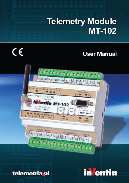
<strong>Telemetry</strong><strong>Module</strong><br />
<strong>MT</strong>-<strong>102</strong><br />
User<strong>Manual</strong><br />
telemetriapl
<strong>Telemetry</strong> <strong>Module</strong><br />
<strong>MT</strong>-<strong>102</strong><br />
User’s <strong>Manual</strong><br />
GSM/GPRS <strong>Telemetry</strong> <strong>Module</strong><br />
for monitoring and control<br />
Class 1 Telecommunications Terminal<br />
Equipment for GSM 850/900/1800/1900<br />
<strong>MT</strong>-<strong>102</strong><br />
INVENTIA Sp. z o.o<br />
v1.46
<strong>MT</strong>-<strong>102</strong><br />
© 2010 Inventia Ltd.<br />
Wszelkie prawa zastrzeżone. Żaden fragment niniejszego dokumentu nie może być powielany lub kopiowany<br />
w żadnej formie bez względu na stosowaną technologię – graficzną, elektroniczną lub mechaniczną, włączając<br />
fotokopiowanie i/lub zapis cyfrowy, również w systemach przechowywania i wyszukiwania dokumentów – bez<br />
pisemnej zgody Wydawcy.<br />
Nazwy produktów wymienionych w niniejszym dokumencie mogą być Znakami Towarowymi i/lub zastrzeżonymi<br />
Znakami Towarowymi należącymi do odpowiednich Właścicieli. Wydawca i Autor oświadczają, że nie roszczą<br />
do tych znaków towarowych żadnych praw.<br />
Pomimo, że niniejsze opracowanie tworzone było z zachowaniem wszelkiej należytej staranności, zarówno Wydawca<br />
jak i Autor nie ponoszą żadnej odpowiedzialności za błędy lub pominięcia w jego treści jak również za straty wynikłe<br />
z wykorzystania zawartej w niniejszym opracowaniu informacji lub ewentualnie towarzyszącego jej oprogramowania.<br />
W żadnym wypadku Wydawca lub Autor nie będą odpowiedzialni za utratę zysku lub inne straty, w tym handlowe,<br />
spowodowane lub rzekomo związane, bezpośrednio lub pośrednio, z niniejszym opracowaniem.<br />
All rights reserved. No parts of this work may be reproduced in any form or by any means - graphic, electronic, or<br />
mechanical, including photocopying, recording, taping, or information storage and retrieval systems - without the<br />
written permission of the publisher.<br />
Products that are referred to in this document may be either trademarks and/or registered trademarks of the<br />
respective owners. The publisher and the author make no claim to these trademarks.<br />
While every precaution has been taken in the preparation of this document, the publisher and the author assume no<br />
responsibility for errors or omissions, or for damages resulting from the use of information contained in this document<br />
or from the use of programs and source code that may accompany it. In no event shall the publisher and the author be<br />
liable for any loss of profit or any other commercial damage caused or alleged to have been caused directly or<br />
indirectly by this document.<br />
Publisher:<br />
Version:<br />
INVENTIA Sp. z o.o.<br />
ul. Kulczyńskiego 14<br />
02-777 Warszawa<br />
Tel: +48 22 545-32-00<br />
inventia@inventia.pl<br />
www.inventia.pl<br />
1.46<br />
Warsaw, July 2010<br />
<strong>MT</strong>C Compatibility:<br />
1.46
INDEX<br />
1. INTRODUCTION ................................................................................................................................................... 8<br />
2. MODULE'S DESTINATION ..................................................................................................................................... 9<br />
3. GSM REQUIREMENTS ........................................................................................................................................... 9<br />
4. MODULE'S DESIGN ............................................................................................................................................... 9<br />
4.1. TOPOGRAPHY .............................................................................................................................................................. 9<br />
4.2. RESOURCES ............................................................................................................................................................... 10<br />
4.2.1. Analogue inputs ............................................................................................................................................ 10<br />
4.2.2. Binary outputs ............................................................................................................................................... 11<br />
4.2.3. Serial ports .................................................................................................................................................... 11<br />
4.2.4. Real time clock .............................................................................................................................................. 12<br />
4.3. INTERNAL RESOURCES ................................................................................................................................................. 12<br />
4.3.1. Registers ........................................................................................................................................................ 12<br />
4.3.2. Virtual registers ............................................................................................................................................. 13<br />
4.3.3. Clocks ............................................................................................................................................................. 13<br />
4.3.4. Counters ........................................................................................................................................................ 13<br />
4.3.5. Logger............................................................................................................................................................ 13<br />
4.3.6. <strong>MT</strong>2<strong>MT</strong> buffer ............................................................................................................................................... 14<br />
4.3.7. Parameters .................................................................................................................................................... 14<br />
4.3.8. System variables ............................................................................................................................................ 14<br />
4.4. LED DIODES .............................................................................................................................................................. 15<br />
4.5. SET BUTTONS ............................................................................................................................................................ 15<br />
4.6. SIM CARD ................................................................................................................................................................ 16<br />
4.7. ANTENNA ................................................................................................................................................................. 16<br />
4.8. POWER SUPPLY .......................................................................................................................................................... 17<br />
4.9. HOUSING .................................................................................................................................................................. 17<br />
5. CONNECTIONS SCHEME ..................................................................................................................................... 17<br />
5.1. BINARY INPUTS/OUTPUTS Q1…Q8 ............................................................................................................................... 17<br />
5.2. ANALOGUE INPUTS A1…A6 ......................................................................................................................................... 18<br />
5.3. COMMUNICATION PORTS ............................................................................................................................................. 19<br />
5.4. POWER SUPPLY .......................................................................................................................................................... 20<br />
6. STARTING THE MODULE ..................................................................................................................................... 21<br />
6.1. CONNECTING ANTENNA ............................................................................................................................................... 21<br />
6.2. FIRST CONFIGURATION ................................................................................................................................................ 22<br />
6.3. INSERTING SIM CARD ................................................................................................................................................. 23<br />
6.4. START UP .................................................................................................................................................................. 24<br />
7. MODULE'S OPERATING MODES .......................................................................................................................... 25<br />
7.1. <strong>MT</strong> SLAVE MODE ....................................................................................................................................................... 25<br />
7.2. TRANSPARENT MODE .................................................................................................................................................. 25<br />
7.3. MODBUS RTU MASTER MODE ..................................................................................................................................... 26<br />
7.4. MODBUS RTU SLAVE MODE ........................................................................................................................................ 27<br />
7.5. MODEM MODE .......................................................................................................................................................... 28<br />
7.6. MODBUS RTU MIRROR MODE ..................................................................................................................................... 28<br />
7.7. TRANSPARENT PLUS MODE ......................................................................................................................................... 29<br />
7.8. GAZMODEM MODE .................................................................................................................................................... 29<br />
7.9. M‐BUS LEC MODE ..................................................................................................................................................... 29<br />
7.10. NMEA 0183 MODE................................................................................................................................................. 30<br />
7.11. FLEXSERIAL MODE .................................................................................................................................................... 30<br />
8. CONFIGURATION ............................................................................................................................................... 31<br />
8.1. GENERAL INFORMATIONS ............................................................................................................................................. 31<br />
1
2<br />
8.2. PARAMETER GROUPS .................................................................................................................................................. 31<br />
8.2.1. Header ........................................................................................................................................................... 32<br />
8.2.1.1. <strong>Module</strong> name ............................................................................................................................................................32<br />
8.2.1.2. <strong>Module</strong> type .............................................................................................................................................................32<br />
8.2.1.3. <strong>Module</strong> serial number ..............................................................................................................................................32<br />
8.2.1.4. IMEI number .............................................................................................................................................................32<br />
8.2.1.5. Internal program version ..........................................................................................................................................33<br />
8.2.1.6. Configuration file version ..........................................................................................................................................33<br />
8.2.1.7. Configuration identifier ............................................................................................................................................33<br />
8.2.1.8. Last configuration date .............................................................................................................................................33<br />
8.2.1.9. Last read of device time ............................................................................................................................................33<br />
8.2.2. General .......................................................................................................................................................... 33<br />
8.2.2.1. Mode of operation ....................................................................................................................................................34<br />
8.2.2.2. SIM card's PIN code ..................................................................................................................................................35<br />
8.2.2.3. GSM band .................................................................................................................................................................35<br />
8.2.2.4. Access to configuration .............................................................................................................................................35<br />
8.2.2.5. Configuration password ............................................................................................................................................36<br />
8.2.2.6. Configuration reading block ......................................................................................................................................36<br />
8.2.2.7. Reset after inactivity .................................................................................................................................................36<br />
8.2.2.8. Data overwriting protection .....................................................................................................................................37<br />
8.2.2.9. Password for data writing .........................................................................................................................................37<br />
8.2.2.10. Error display time....................................................................................................................................................37<br />
8.2.2.11. Use of GPRS ............................................................................................................................................................37<br />
8.2.2.12. Use of SMS ..............................................................................................................................................................38<br />
8.2.2.13. Monthly SMS limit ..................................................................................................................................................38<br />
8.2.2.14. Roaming ..................................................................................................................................................................38<br />
8.2.3. GPRS .............................................................................................................................................................. 39<br />
8.2.3.1. APN name .................................................................................................................................................................39<br />
8.2.3.2. APN user name .........................................................................................................................................................39<br />
8.2.3.3. APN password ...........................................................................................................................................................39<br />
8.2.3.4. <strong>Module</strong>'s IP ...............................................................................................................................................................39<br />
8.2.3.5. IP assignment ............................................................................................................................................................40<br />
8.2.3.6. Virtual IP address ......................................................................................................................................................40<br />
8.2.3.7. Number of GPRS transmission retries .......................................................................................................................40<br />
8.2.3.8. Transmission timeout ...............................................................................................................................................41<br />
8.2.3.9. Idle time ....................................................................................................................................................................41<br />
8.2.3.10. GPRS testing IP address ..........................................................................................................................................41<br />
8.2.3.11. Number of login retries ...........................................................................................................................................42<br />
8.2.3.12. Wait time after disconnection ................................................................................................................................42<br />
8.2.3.13. Data frame format ..................................................................................................................................................42<br />
8.2.3.14. Proxy server IP address ...........................................................................................................................................43<br />
8.2.3.15. CRC compatibility ....................................................................................................................................................43<br />
8.2.4. Authorized numbers ...................................................................................................................................... 43<br />
8.2.4.1. Number of phone numbers ......................................................................................................................................43<br />
8.2.4.2. Number of IP numbers..............................................................................................................................................44<br />
8.2.4.3. Phone ........................................................................................................................................................................44<br />
8.2.4.4. IP ...............................................................................................................................................................................44<br />
8.2.5. Mode of operation ........................................................................................................................................ 45<br />
8.2.5.1. Transparent mode ....................................................................................................................................................45<br />
8.2.5.1.1. GPRS transmission ............................................................................................................................................45<br />
8.2.5.1.1.1. Max. length of data packet ......................................................................................................................45<br />
8.2.5.1.1.2. Data packet delimiter ...............................................................................................................................46<br />
8.2.5.1.1.3. Channel reservation time .........................................................................................................................46<br />
8.2.5.1.1.4. Routing .....................................................................................................................................................46<br />
8.2.5.1.1.5. Address offset ..........................................................................................................................................47<br />
8.2.5.1.1.6. Broadcast address ....................................................................................................................................47<br />
8.2.5.1.1.7. Routing table size .....................................................................................................................................47<br />
8.2.5.1.2. Routing table ....................................................................................................................................................47<br />
8.2.5.2. Modbus RTU Master mode .......................................................................................................................................48<br />
8.2.5.2.1. Routing table size .............................................................................................................................................48<br />
8.2.5.2.2. Routing table ....................................................................................................................................................48<br />
8.2.5.3. Modbus RTU Slave mode ..........................................................................................................................................48<br />
8.2.5.3.1. Routing table size .............................................................................................................................................49
8.2.5.3.2. Routing table ................................................................................................................................................ 49<br />
8.2.5.4. Modbus RTU Mirror mode .................................................................................................................................... 49<br />
8.2.5.4.1. Number of data blocks ................................................................................................................................. 49<br />
8.2.5.4.2. Delay after error in communication with SLAVE ......................................................................................... 50<br />
8.2.5.4.3. Data block 1...16 ........................................................................................................................................... 50<br />
8.2.5.4.3.1. Modbus ID of Slave device ................................................................................................................... 50<br />
8.2.5.4.3.2. Space .................................................................................................................................................... 50<br />
8.2.5.4.3.3. Address of mapped space in SLAVE ...................................................................................................... 51<br />
8.2.5.4.3.4. Mapped space size ............................................................................................................................... 51<br />
8.2.5.4.3.5. Mapped space read interval ................................................................................................................. 51<br />
8.2.5.4.3.6. Address of mapped space in module ................................................................................................... 51<br />
8.2.5.4.3.7. Force write the whole block ................................................................................................................. 52<br />
8.2.5.5. Transparent PLUS mode ...................................................................................................................................... 52<br />
8.2.5.5.1. Max. length of data packet ........................................................................................................................... 52<br />
8.2.5.5.2. Data packet delimiter ................................................................................................................................... 52<br />
8.2.5.5.3. Channel reservation time ............................................................................................................................. 52<br />
8.2.5.6. GazModem mode ................................................................................................................................................. 53<br />
8.2.5.6.1. Read interval ................................................................................................................................................. 53<br />
8.2.5.6.2. Number of retries ......................................................................................................................................... 53<br />
8.2.5.6.3. Transmission timeout ................................................................................................................................... 54<br />
8.2.5.6.4. Threshold hysteresis ..................................................................................................................................... 54<br />
8.2.5.6.5. Alarm station IP address ............................................................................................................................... 54<br />
8.2.5.6.6. Number of devices ........................................................................................................................................ 54<br />
8.2.5.6.7. MC 1....16 ..................................................................................................................................................... 55<br />
8.2.5.6.7.1. Address ................................................................................................................................................. 55<br />
8.2.5.6.7.2. Alarm reading ....................................................................................................................................... 55<br />
8.2.5.6.7.3. Signal reading ....................................................................................................................................... 55<br />
8.2.5.6.7.4. Current data reading ............................................................................................................................ 55<br />
8.2.5.6.7.5. Current data block index ...................................................................................................................... 56<br />
8.2.5.6.7.6. Current data block length ..................................................................................................................... 56<br />
8.2.5.7. M‐Bus LEC mode ................................................................................................................................................... 56<br />
8.2.5.7.1. Read interval ................................................................................................................................................. 56<br />
8.2.5.7.2. Number of retries ......................................................................................................................................... 57<br />
8.2.5.7.3. Transmission timeout ................................................................................................................................... 57<br />
8.2.5.7.4. Threshold hysteresis ..................................................................................................................................... 57<br />
8.2.5.7.5. Gas meter address ........................................................................................................................................ 57<br />
8.2.5.7.6. Gas meter reading interval ........................................................................................................................... 57<br />
8.2.5.7.7. Number of transmission retries to gas meter............................................................................................... 58<br />
8.2.5.7.8. Transmission timeout for gas meter ............................................................................................................ 58<br />
8.2.5.7.9. Number of devices ........................................................................................................................................ 58<br />
8.2.5.7.10. MC .............................................................................................................................................................. 58<br />
8.2.5.7.10.1. Address 1...16 ..................................................................................................................................... 58<br />
8.2.5.7.10.2. Geographical coordinates format ...................................................................................................... 58<br />
8.2.5.7.10.3. Identifier 1...16 ................................................................................................................................... 59<br />
8.2.5.8. NMEA 0183 mode ................................................................................................................................................. 59<br />
8.2.5.8.1. Data validity time ......................................................................................................................................... 59<br />
8.2.5.9. FlexSerial ............................................................................................................................................................... 59<br />
8.2.5.9.1. Max. length of data packet ........................................................................................................................... 59<br />
8.2.5.9.2. Data packet delimiter ................................................................................................................................... 60<br />
8.2.6. Resources ................................................................................................................................................... 60<br />
8.2.6.1. Modbus ID number of module's internal resources ............................................................................................. 60<br />
8.2.6.2. Terminals .............................................................................................................................................................. 60<br />
8.2.6.2.1. Binary outputs Q1...Q8 ................................................................................................................................. 60<br />
8.2.6.2.1.1. Name .................................................................................................................................................... 60<br />
8.2.6.2.1.2. Operating modes .................................................................................................................................. 61<br />
8.2.6.2.1.2.1. Binary input .................................................................................................................................. 61<br />
8.2.6.2.1.2.1.1. Filtering constant ................................................................................................................. 61<br />
8.2.6.2.1.2.2. Analogue inputs ........................................................................................................................... 61<br />
8.2.6.2.1.2.2.1. Engineering units ................................................................................................................. 62<br />
8.2.6.2.1.2.2.2. Low reference ‐ internal units .............................................................................................. 62<br />
8.2.6.2.1.2.2.3. Low reference ‐ engineering units ....................................................................................... 62<br />
8.2.6.2.1.2.2.4. High reference ‐ internal units ............................................................................................. 62<br />
8.2.6.2.1.2.2.5. High reference ‐ engineering units ...................................................................................... 63<br />
3
4<br />
8.2.6.2.1.2.2.6. Alarm HiHi ............................................................................................................................... 63<br />
8.2.6.2.1.2.2.7. Alarm Hi .................................................................................................................................. 63<br />
8.2.6.2.1.2.2.8. Alarm Lo .................................................................................................................................. 63<br />
8.2.6.2.1.2.2.9. Alarm LoLo .............................................................................................................................. 64<br />
8.2.6.2.1.2.2.10. Alarm hysteresis ................................................................................................................... 64<br />
8.2.6.2.1.2.2.11. Dead band ............................................................................................................................. 64<br />
8.2.6.2.1.2.3. Counter inputs ................................................................................................................................ 64<br />
8.2.6.2.1.2.3.1. Counting direction .................................................................................................................. 64<br />
8.2.6.2.1.2.3.2. Counting range ....................................................................................................................... 65<br />
8.2.6.2.1.2.3.3. Activating slope ...................................................................................................................... 65<br />
8.2.6.2.1.2.3.4. Filtering constant .................................................................................................................... 65<br />
8.2.6.2.1.2.4. Binary outputs ................................................................................................................................. 65<br />
8.2.6.2.2. Analogue inputs AN1, AN2, AE3, ..., AE6 ......................................................................................................... 65<br />
8.2.6.2.2.1. Name ....................................................................................................................................................... 66<br />
8.2.6.2.2.2. Operating mode ...................................................................................................................................... 66<br />
8.2.6.2.2.3. Filtering constant .................................................................................................................................... 66<br />
8.2.6.2.2.4. Engineering units ..................................................................................................................................... 66<br />
8.2.6.2.2.5. Low reference ‐ internal units ................................................................................................................. 67<br />
8.2.6.2.2.6. Low reference ‐ engineering units ........................................................................................................... 67<br />
8.2.6.2.2.7. High reference ‐ internal units ................................................................................................................ 67<br />
8.2.6.2.2.8. High reference ‐ engineering units .......................................................................................................... 67<br />
8.2.6.2.2.9. Alarm HiHi ............................................................................................................................................... 67<br />
8.2.6.2.2.10. Alarm Hi ................................................................................................................................................. 68<br />
8.2.6.2.2.11. Alarm Lo ................................................................................................................................................ 68<br />
8.2.6.2.2.12. Alarm LoLo ............................................................................................................................................ 68<br />
8.2.6.2.2.13. Alarm hysteresis .................................................................................................................................... 68<br />
8.2.6.2.2.14. Dead band ............................................................................................................................................. 69<br />
8.2.6.3. Serial port ................................................................................................................................................................ 69<br />
8.2.6.3.1. Interface type .................................................................................................................................................. 69<br />
8.2.6.3.2. Transmission speed ......................................................................................................................................... 69<br />
8.2.6.3.3. Stop bits ........................................................................................................................................................... 69<br />
8.2.6.3.4. Parity ............................................................................................................................................................... 70<br />
8.2.6.4. Asynchronous clocks ................................................................................................................................................ 70<br />
8.2.6.4.1. Clocks TMR1, TMR2 ......................................................................................................................................... 70<br />
8.2.6.4.1.1. Period ...................................................................................................................................................... 70<br />
8.2.6.5. Synchronous clocks .................................................................................................................................................. 70<br />
8.2.6.5.1. Clock TMR3, TMR4........................................................................................................................................... 70<br />
8.2.6.5.1.1. Start ......................................................................................................................................................... 70<br />
8.2.6.5.1.2. Period ...................................................................................................................................................... 71<br />
8.2.6.6. Datalogger ............................................................................................................................................................... 71<br />
8.2.6.6.1. Active ............................................................................................................................................................... 71<br />
8.2.6.6.2. Sampling interval ............................................................................................................................................. 71<br />
8.2.6.6.3. Buffer flush mode ............................................................................................................................................ 71<br />
8.2.6.6.4. Buffer flush interval ......................................................................................................................................... 72<br />
8.2.6.6.5. Recipient IP address ........................................................................................................................................ 72<br />
8.2.6.7. <strong>MT</strong>2<strong>MT</strong> Buffer.......................................................................................................................................................... 72<br />
8.2.6.7.1. Active ............................................................................................................................................................... 72<br />
8.2.6.7.2. Sending to PORT2 ............................................................................................................................................ 73<br />
8.2.6.7.3. Buffer address ................................................................................................................................................. 73<br />
8.2.6.7.4. Buffer size ........................................................................................................................................................ 73<br />
8.2.6.8. Constant parameters ............................................................................................................................................... 73<br />
8.2.6.8.1. Number of parameters .................................................................................................................................... 73<br />
8.2.6.8.2. Parameter 1...128 ............................................................................................................................................ 74<br />
8.2.7. Rules ............................................................................................................................................................. 74<br />
8.2.7.1. SMS sending ............................................................................................................................................................. 74<br />
8.2.7.1.1. Number of SMS sending rules ......................................................................................................................... 74<br />
8.2.7.1.2. SMS sending rule ............................................................................................................................................. 75<br />
8.2.7.1.2.1. Trigger input ............................................................................................................................................ 75<br />
8.2.7.1.2.2. Trigger flag .............................................................................................................................................. 75<br />
8.2.7.1.2.3. SMS text .................................................................................................................................................. 75<br />
8.2.7.1.2.4. Recipient number .................................................................................................................................... 76<br />
8.2.7.1.2.5. Sending additional information ............................................................................................................... 76<br />
8.2.7.2. Data sending ............................................................................................................................................................ 76
8.2.7.2.1. Number of data sending rules ......................................................................................................................... 77<br />
8.2.7.2.1.1. Data sending rule .................................................................................................................................... 77<br />
8.2.7.2.1.1.1. Trigger input .................................................................................................................................... 77<br />
8.2.7.2.1.1.2. Trigger flag ...................................................................................................................................... 77<br />
8.2.7.2.1.1.3. IP address ........................................................................................................................................ 78<br />
8.2.7.2.1.1.4. Send ................................................................................................................................................ 78<br />
8.2.7.2.1.1.5. Buffer address ................................................................................................................................. 78<br />
8.2.7.2.1.1.6. Buffer size ....................................................................................................................................... 78<br />
8.2.7.3. CLIP calls .................................................................................................................................................................. 79<br />
8.2.7.3.1. Number of CLIP calls rules ............................................................................................................................... 79<br />
8.2.7.3.2. Number of trials .............................................................................................................................................. 80<br />
8.2.7.3.3. Interval between trials .................................................................................................................................... 80<br />
8.2.7.3.4. CLIP call rule .................................................................................................................................................... 80<br />
8.2.7.3.4.1. Trigger input ............................................................................................................................................ 80<br />
8.2.7.3.4.2. Trigger flag .............................................................................................................................................. 81<br />
8.2.7.3.4.3. Recipient number .................................................................................................................................... 81<br />
8.2.7.3.4.4. Calling time .............................................................................................................................................. 81<br />
8.3. CONFIGURATION WRITING .......................................................................................................................................... 81<br />
8.4. VERIFICATION OF CONFIGURATION ................................................................................................................................ 82<br />
9. PROGRAMMING ................................................................................................................................................ 82<br />
9.1. GENERAL INFORMATION ............................................................................................................................................. 82<br />
9.2. STARTING TO WORK ................................................................................................................................................... 82<br />
9.3. MAIN WINDOW LAYOUT ............................................................................................................................................. 84<br />
9.3.1. Menu items .................................................................................................................................................. 85<br />
9.3.1.1. File ........................................................................................................................................................................... 85<br />
9.3.1.2. Edit ........................................................................................................................................................................... 86<br />
9.3.1.3. <strong>Module</strong>..................................................................................................................................................................... 87<br />
9.3.1.4. Help .......................................................................................................................................................................... 90<br />
9.3.1.5. Toolbar ..................................................................................................................................................................... 91<br />
9.4. PROGRAM EDITOR TABLE ............................................................................................................................................ 91<br />
9.5. STANDARD FUNCTIONS ............................................................................................................................................... 92<br />
9.6. NUMERIC KEYBOARD .................................................................................................................................................. 93<br />
9.7. AUXILIARY FUNCTIONS ................................................................................................................................................ 93<br />
9.8. DESCRIPTION OF PROGRAM FUNCTIONS ........................................................................................................................ 94<br />
9.9. DESCRIPTION OF INTERNAL FUNCTION BLOCKS ............................................................................................................... 103<br />
9.9.1. Timers T1...T8 ............................................................................................................................................. 103<br />
9.9.2. Counters C1...C8 ......................................................................................................................................... 104<br />
9.10. SIGNAL LEVELS OR EDGES ........................................................................................................................................ 104<br />
9.11. FILLING AND MODIFYING PROGRAM TABLE ................................................................................................................. 105<br />
9.12. DOWNLODING THE PROGRAM .................................................................................................................................. 106<br />
9.13. VERIFYING THE PROGRAM ....................................................................................................................................... 106<br />
9.14. EXAMPLES OF PROGRAMS ....................................................................................................................................... 106<br />
9.14.1. The timer .................................................................................................................................................. 106<br />
9.14.2. The counter .............................................................................................................................................. 107<br />
9.14.3. Pulse generator ........................................................................................................................................ 107<br />
9.14.4. 2 pumps alternating action ...................................................................................................................... 108<br />
9.14.5. Checking bit's value in the registry ........................................................................................................... 109<br />
9.14.6. Alarm with confirmation .......................................................................................................................... 110<br />
9.14.7. Motion detector ....................................................................................................................................... 111<br />
9.14.8. Logger program ........................................................................................................................................ 112<br />
10. PROBLEM SOLVING ........................................................................................................................................ 112<br />
10.1. LED SIGNALLING ................................................................................................................................................... 112<br />
10.1.1. Inputs/Outputs Q1....Q8 ........................................................................................................................... 113<br />
10.1.2. Analog inputs AN3...AN6 .......................................................................................................................... 113<br />
10.1.3. GSM status ............................................................................................................................................... 114<br />
10.1.4. GSM activity ............................................................................................................................................. 115<br />
10.1.5. GSM signal level ....................................................................................................................................... 115<br />
5
10.1.6. PORT 2 activity ......................................................................................................................................... 116<br />
10.1.7. <strong>Module</strong>'s status ........................................................................................................................................ 117<br />
10.1.8. SET1, SET2 alarm thresholds .................................................................................................................... 118<br />
10.2. UNBLOCKING OF SIM CARD .................................................................................................................................... 118<br />
10.3. ERROR SIGNALLING ................................................................................................................................................ 119<br />
10.3.1. Standard errors ........................................................................................................................................ 119<br />
10.3.2. Critical errors ............................................................................................................................................ 120<br />
11. TECHNICAL DATA ........................................................................................................................................... 122<br />
11.1. GENERAL ............................................................................................................................................................. 122<br />
11.2. GSM/GPRS MODEM ........................................................................................................................................... 122<br />
11.3. POWER SUPPLY ..................................................................................................................................................... 123<br />
11.4. BINARY OUTPUTS Q1...Q8 ..................................................................................................................................... 123<br />
11.5. ANALOGUE INPUTS AN1...AN6 ............................................................................................................................... 123<br />
11.6. DRAWINGS AND DIMENSIONS .................................................................................................................................. 124<br />
12. SAFETY INFORMATIONS ................................................................................................................................. 126<br />
12.1. WORKING ENVIRONMENT ....................................................................................................................................... 126<br />
12.2. ELECTRONIC EQUIPMENT ........................................................................................................................................ 126<br />
12.2.1. Heart pacemakers .................................................................................................................................... 126<br />
12.2.2. Hearing aids ............................................................................................................................................. 126<br />
12.2.3. Other medical equipment ......................................................................................................................... 126<br />
12.2.4. RF Marked equipment .............................................................................................................................. 126<br />
12.3. EXPLOSIVE ENVIRONMENT ....................................................................................................................................... 126<br />
13. APPENDICES ................................................................................................................................................... 127<br />
13.1. DATA TRANSMISSION IN GSM SYSTEMS ..................................................................................................................... 127<br />
13.1.1. SMS ........................................................................................................................................................... 127<br />
13.1.2. CSD (HSCSD) ............................................................................................................................................. 127<br />
13.1.3. GPRS ......................................................................................................................................................... 127<br />
13.1.3.1. Advantages of GPRS technology .......................................................................................................................... 128<br />
13.1.3.2. GPRS in telemetry applications ........................................................................................................................... 128<br />
13.1.4. EDGE ......................................................................................................................................................... 128<br />
13.1.5. U<strong>MT</strong>S ........................................................................................................................................................ 129<br />
13.1.6. HSDPA ...................................................................................................................................................... 129<br />
13.2. APPLICATION EXAMPLES ......................................................................................................................................... 129<br />
13.2.1. Communication with single module ......................................................................................................... 129<br />
13.2.2. Point to point communication .................................................................................................................. 130<br />
13.2.2.1. Using internal resources ...................................................................................................................................... 130<br />
13.2.2.2. Data transmission from external devices ............................................................................................................. 131<br />
13.2.2.2.1. Configuration for transparent mode ........................................................................................................... 131<br />
13.2.2.2.2. Configuration for GazModem mode ............................................................................................................ 132<br />
13.2.2.2.3. Configuration for M‐Bus Lec mode .............................................................................................................. 132<br />
13.2.2.2.4. Configuration for NMEA 0183 mode ........................................................................................................... 133<br />
13.3. SYNTAX FOR READING AND WRITING DATA IN SMS MODE ............................................................................................. 133<br />
13.4. UNLOCKING WRITING TO INTERNAL REGISTERS ............................................................................................................ 135<br />
13.5. WORKING WITH DYNAMIC IP ADDRESSING ................................................................................................................. 135<br />
13.6. DATA FORMATS .................................................................................................................................................... 136<br />
13.7. MODULE'S STATUS FORMAT .................................................................................................................................... 137<br />
13.8. TRIGGER INPUTS.................................................................................................................................................... 138<br />
13.9. FLAGS ................................................................................................................................................................. 138<br />
13.10. RM‐120 ........................................................................................................................................................... 140<br />
13.11. MEMORY MAP .................................................................................................................................................... 141<br />
13.11.1. Binary inputs space ................................................................................................................................ 141<br />
13.11.2. Binary outputs space .............................................................................................................................. 144<br />
13.11.3. Analogue inputs space ........................................................................................................................... 146<br />
13.11.4. Internal registers space .......................................................................................................................... 148<br />
13.11.5. Auxiliary resources for GazModem mode .............................................................................................. 151<br />
6
13.11.6. Auxiliary resources for M‐Bus mode ........................................................................................................ 154<br />
13.11.7. Auxiliary resources for NMEA 0183 mode ............................................................................................... 159<br />
7
1. Introduction<br />
Despite the explosive expansion of mobile phone networks and the per definition digital<br />
nature of transmission utilized by them, these networks were not well-suited for the transfer<br />
of digital data streams until recently. The applied technologies used traditional modem<br />
protocols. This meant that the need to use circuit-switched mode for establishing<br />
connections and transmission capabilities was limited to point-to-point connections. Thus, we<br />
had to do with the typical analogue circuit-switched links technology used in traditional<br />
telephone systems adapted to the wireless digital transmission environment. A connection<br />
established for data transmission occupied the whole voice channel. As a result,<br />
simultaneous phone calls were impossible, and the cost of transmission depended on the<br />
connection time rather than the amount of the transferred data. In this situation, the realtime<br />
monitoring of units requiring constant supervision but generating a relatively small<br />
amount of data was not possible.<br />
The situation changed radically after GSM operators introduced data transmission services in<br />
the GPRS (General Packet Radio Services) standard. The new technology, called the 2.5G<br />
standard - meaning Two and a Half Generation, is a bridge between the to-date technologies<br />
of the Second-Generation GSM networks (2G) and the Third-Generation technology (3G -<br />
U<strong>MT</strong>S) which has been waiting for application on a wide scale. However, broadband 3G<br />
technology is still very distant. So let us deal with the solutions available right now.<br />
In providing this user’s manual, we are aware that it will not answer all your questions and<br />
address all your doubts. This is why the manual will be regularly supplemented and modified.<br />
We ask for your comments and welcome suggestions in order to make this manual more<br />
useful.<br />
INVENTIA Ltd.<br />
8
2. <strong>Module</strong>'s destination<br />
<strong>MT</strong>-<strong>102</strong> is a specialized telemetry module optimized for application in advanced<br />
measurement and alarm systems provided with a mains power supply.<br />
General attributes of <strong>MT</strong>-<strong>102</strong>:<br />
Compact design<br />
Reach input/output set<br />
Local logging of measurement results<br />
Local execution of user program<br />
Ability to extend network with local extension modules<br />
Spontaneous transmission of data on occurrence of pre-defined alert states enabling<br />
application on objects requiring continuous monitoring.<br />
A typical application field for <strong>MT</strong>-<strong>102</strong> is all installations requiring local control and<br />
transmission of data to remote monitoring center.<br />
We encourage getting acquainted with the modules configuration and modes of operation<br />
along with examples of application in different configurations described in appendices.<br />
3. GSM requirements<br />
For proper operation, the module needs a SIM card supplied by a GSM operator providing<br />
GPRS and/or SMS services.<br />
The GPRS/enabled SIM card has to be registered in the APN with static IP addressing. The<br />
unique IP address of the SIM card is an identification for the module within the APN. This<br />
enables module-to-module and module-to-server communication within the APN structure.<br />
A good and strong GSM signal in the place where the module's antenna is located is<br />
imperative for the proper function of the module. Using the module in places where the<br />
signal is weak may lead to interruptions in transmission and possible loss of transmitted data<br />
along with increased costs generated by transmission retries.<br />
4. <strong>Module</strong>'s design<br />
4.1. Topography<br />
9
4.2. Resources<br />
<strong>MT</strong>-<strong>102</strong> module's resources<br />
Q - binary outputs 8<br />
0<br />
C - counters<br />
(+ 8)<br />
AI - analogue inputs 6<br />
(+ 8)<br />
Serial PORT 1 1<br />
Serial PORT 2 1<br />
working as:<br />
binary output<br />
binary input<br />
counter input<br />
analogue input f/U<br />
each output can work as a counter input<br />
4 - 20 mA<br />
as analogue f/U created of binary outputs<br />
standard RS-232 - configuration and Modbus RTU<br />
Slave (ID1, 9600, hardware handshake [CTS/RTS])<br />
standard RS-232/422/485 - different communication<br />
protocols<br />
4.2.1. Analogue inputs<br />
The <strong>MT</strong>-<strong>102</strong> <strong>Telemetry</strong> <strong>Module</strong> is equipped with six 4-20 mA analog inputs marked as AN1,<br />
AN2, …, AN5 and AN6. The inputs are isolated both from each other and from the rest of<br />
the device, enabling the easy connectivity of the signal sources with different ground<br />
potentials. The AN1, AN2 analog inputs are the only inputs with manually-set alarm levels,<br />
set by SET buttons on the front panel of the device. This allows changing the alarm level<br />
easily without the need to use the <strong>MT</strong>M configuration program.<br />
10
Additionally, users may create up to 8 analog inputs by reconfiguring binary outputs Q1-Q8<br />
to work in quasi/analog mode. After reconfiguration, all inputs work in input signal<br />
frequency-to-analog conversion, so for proper operation, one has to connect analog signal<br />
source via analog-to-frequency converter which outputs a square wave of frequency<br />
proportional to analog signal. Input signal conversion range is 0-2kHz.<br />
During configuration of analogue inputs, the user can set engineering units and precisely<br />
rescale the input signal. The alarm levels and the time of input signal integration are also<br />
configurable. The possibility to configure as much as four - and in the case of the AN1 and<br />
AN2 inputs five - alarm levels guarantees supervision flexibility of monitoring of analogue<br />
signals.<br />
Additional information about manually/set threshold levels for AN1 and AN2 are described in<br />
chapter SET buttons.<br />
Analogue inputs have two parameters defined. They are Hysteresis and Dead band. The<br />
value of hysteresis defines insensitivity of device for signal variations near threshold values<br />
preventing excessive generation of events. The range of hysteresis allows generating event<br />
only when the signal on the input changes by defined value. Hysteresis is set for all selected<br />
analogue input alarm thresholds.<br />
Flags AnLoLo, AnLo, AnHi, AnHiHi, An DB, An Set Fall, An Set Rise, set by analogue signal<br />
changes may be employed for rules processing.<br />
4.2.2. Binary outputs<br />
<strong>MT</strong>-<strong>102</strong> <strong>Telemetry</strong> module is equipped with 8 dedicated binary outputs marked Q1…Q8.<br />
The state of outputs is set by writing desired value into a binary outputs memory register.<br />
This record may be performed either remotely via GPRS or locally as the execution of a userdefined<br />
program.<br />
For each binary output, the state of forcing signal is compared with actual output state<br />
signal. Upon detection of discrepancy, the Bi Out Err Flag is raised and may be used for rules<br />
processing.<br />
Any binary output may be individually configured to work as binary input. The change of the<br />
input signal sets the alarm flag, connected with the corresponding binary input Q1–Q8,<br />
respectively as Bi In 0->1, Bi In 1->0 and Bi In Chg. The flags may be used in rules<br />
processing.<br />
Each of the binary outputs Q1–Q8 may be configured independently also to work in the<br />
counter or analogue mode. The use of binary output in these additional modes will be<br />
presented further in respective sections of this manual.<br />
4.2.3. Serial ports<br />
<strong>MT</strong>-<strong>102</strong> <strong>Telemetry</strong> <strong>Module</strong> is equipped with two serial ports PORT1 and PORT2.<br />
PORT1 works only in RS-232 mode and is dedicated to local configuration of parameters. In<br />
order to perform local configuration, connect this port to a PC-class computer with running<br />
<strong>MT</strong>M program. Operating parameters of this port are not modifiable. The length of the<br />
connecting cable should not exceed 3 m. This port is not isolated!<br />
PORT1 can also be used as Modbus RTU Slave port without need of changing modules<br />
configuration. <strong>Module</strong>'s Modbus ID on this port is always 1 (options in configuration apply<br />
only to PORT2).<br />
11
Transmission parameters are:<br />
speed of 9600bps,<br />
8 data bits,<br />
no parity,<br />
1 stop bit,<br />
hardware handshake (RTS/CTS).<br />
This port is ideal for connecting external graphical or text panel supporting Modbus RTU<br />
Master.<br />
NOTICE!<br />
The first configuration has to be performed locally, via PORT1 in order to<br />
provide the module with basic GPRS communication parameters like PIN code<br />
and APN name.<br />
PORT2 is capable of operating in RS-232/422/485 modes and serves communication with<br />
external data sources. The interface and operating mode is selected during module's<br />
configuration. This port is optoisolated.<br />
4.2.4. Real time clock<br />
<strong>MT</strong>-<strong>102</strong> <strong>Module</strong> is equipped with astronomical time clock (RTC).<br />
The clock is a base for defining working cycles of module, timers and time stamps for<br />
measurement results recorded in registers. Imprecise clock setting results in faulty time<br />
stamping and subsequent loss of vital information. For that reason, it is recommended to<br />
set the clock to UTC time instead of the local time zone of the module's placement.<br />
CAUTION!<br />
The module's RTC clock does not automatically adjust to summer/winter<br />
time. To avoid loss of data during manual time adjustment, UTC time is<br />
recommended.<br />
CAUTION!<br />
The RTC clock is powered from an internal battery, and as long as it is<br />
operational there is no need to reset the time after power-off. Since the<br />
clock precision is not absolute, periodical time adjustment may be<br />
necessary.<br />
Setting the time is described in configuring mode documentation for the <strong>MT</strong>M program.<br />
4.3. Internal resources<br />
4.3.1. Registers<br />
<strong>MT</strong>-<strong>102</strong> <strong>Telemetry</strong> module has in its internal resources 16 bit input registers and 16 bit<br />
internal registers. Remote access to these areas is possible using standard Modbus<br />
commands.<br />
Internal Registers are not reset at power off.<br />
Input Registers are reset at power on.<br />
12
<strong>Module</strong>'s 16 bit registers store unsigned values in range 0-65535. In order to increase the<br />
range of stored values, pairs of 16 bit registers were reserved to create 32 bit registers<br />
storing signed values for use in user-defined internal program.<br />
4.3.2. Virtual registers<br />
<strong>MT</strong>-<strong>102</strong> <strong>Telemetry</strong> module feature 16 bit Virtual Registers. They reflect input (VREG_BIx)<br />
and output (VREG_BOx) bit spaces. Using virtual registers gives easy access to bit groups<br />
and copying data between bit spaces and registers. Access to registers is possible through<br />
module's internal program using standard programming functions described in the chapter<br />
Programming.<br />
4.3.3. Clocks<br />
<strong>MT</strong>-<strong>102</strong> <strong>Telemetry</strong> <strong>Module</strong> is equipped with 4 programmatic clocks divided in two groups<br />
with different functionalities.<br />
2 programmable Asynchronous clocks TMR1, TMR2, enable cyclical time measuring for up<br />
to 100 days (8 640 000 s) and 2 programmable Synchronous clocks TMR3, TMR4, enable<br />
cyclical time measuring from 1 min to 24 h with synchronization with module z RTC clock.<br />
Properly configured clock counts the time setting after each completed period, for one<br />
program cycle, a flag in binary inputs space (respective TMR1, TMR2, TMR3, TMR4). These<br />
flags can be used in internal controlling program or for triggering transmission on event.<br />
4.3.4. Counters<br />
Each of <strong>MT</strong>-<strong>102</strong> module's outputs is capable of counting pulses and storing the value in 32<br />
bit counter with capacity of 2 147 483 647 (31 bits + counting direction bit ) events. The<br />
counter can count „up” or „down”, and the range can be freely defined in range of 1 to 2 147<br />
483 647.<br />
Counting "up" means that the counter value is increased by 1 for each detected pulse and<br />
after reaching the value set as "counter length-1" is reset to "0". Counting "down" diminishes<br />
the counter value by 1 for each detected pulse and after reaching the value set as "counter<br />
length-1" is reset to "0" to resume the value of defined maximum.<br />
Crossing the value of counter length sets Counter alarm flag for respective input. The flag<br />
can be used in the internal controlling program or for triggering transmission on event.<br />
4.3.5. Logger<br />
<strong>MT</strong>-<strong>102</strong> <strong>Telemetry</strong> <strong>Module</strong> is equipped with internal Recorder, storing state changes on<br />
binary inputs/outputs and on analogue inputs. The Recorder has a volume of 75 data<br />
records. New records are written to memory after change of state on binary inputs/outputs<br />
or at crossing of dead band defined for analogue inputs. Records are stamped with time<br />
stamp from module's internal real time clock (RTC). It is recommended to set module's RTC<br />
compliant to UTC for preserving data integrity.<br />
Data written in the recorder is transmitted accordingly to configured options to defined IP<br />
address. Confirmation of reception removes records from the recorder.<br />
NOTICE!<br />
The recorder function is available only in GPRS mode.<br />
13
4.3.6. <strong>MT</strong>2<strong>MT</strong> buffer<br />
<strong>MT</strong>2<strong>MT</strong> buffer enables creation of system where <strong>MT</strong>-101/<strong>102</strong>/202 modules may exchange<br />
information (Internal Registers) with each other without any relaying instance.<br />
Data transmission from one module to another goes like this:<br />
1. In sending module the event/triggered sending of the buffer has to be defined.<br />
2. In receiving module switch the <strong>MT</strong>2<strong>MT</strong> buffer on and define its placement and size so that<br />
it encompasses the area of sent registers.<br />
3. Upon reception of event-triggered data frame, registers from event-reporting module are<br />
copied into receiving module's registers and <strong>MT</strong>2<strong>MT</strong>_x bit informing about modification of<br />
<strong>MT</strong>2<strong>MT</strong> buffer with data from respective IP is set. (Bit number reflects the index of IP<br />
address in GPRS/Authorized numbers in configuration). <strong>MT</strong>2<strong>MT</strong>_x bits are set for 1<br />
program cycle immediately after reception and recording it in <strong>MT</strong>2<strong>MT</strong> buffer.<br />
4. Data transmission in this system copies registers of sending module into the exact same<br />
register in receiving module. When designing communication between larger numbers of<br />
modules, separate register areas have to be sent and appropriately large areas define for<br />
<strong>MT</strong>2<strong>MT</strong> receiving buffer in receiving modules.<br />
4.3.7. Parameters<br />
In <strong>MT</strong>-<strong>102</strong> module max. 64 constant parameters that are loaded into module's memory<br />
during initialization of the module can be defined.<br />
These constants are stored in 16 bit registers and have numerical values ranging from 0 –<br />
65535.<br />
Constant parameters may be used for parameterization of user programs.<br />
Defined parameters are not reset after power loss or module is reset.<br />
4.3.8. System variables<br />
<strong>MT</strong>-<strong>102</strong> has system variables connected to GSM/GPRS connection state and power supply.<br />
Variables state is reflected by flags that can be used as transmission triggers or in internal<br />
control programs.<br />
FS1_ups = 1 loss of potential at module's UPS pin<br />
FS1_q+ = 1 loss of power supply for binary outputs Q1…Q8<br />
FS1_gprs = 1 informs upon log off from GPRS network<br />
Full list of system variables is placed in Memory map chapter in Appendices.<br />
14
4.4. LED diodes<br />
LED indicators placed on <strong>MT</strong>-<strong>102</strong> front panel are convenient during module start up phase.<br />
Detailed description of signaling patterns is placed in chapter LED signaling.<br />
4.5. SET buttons<br />
SET buttons placed on <strong>MT</strong>-<strong>102</strong> front panel are for manual setting of auxiliary alarm<br />
thresholds for analogue inputs A1 and A2.<br />
<strong>Manual</strong>ly set thresholds cannot be modified or read during configuration of module.<br />
There are two flags connected to these thresholds, ANX_Set_F and ANX_Set_R, informing<br />
about crossing of the set level, and two alarms - An Set Fall and An Set Rise that may be<br />
used for rule processing.<br />
15
As shown by graph, the value at which flags ANX_Set_F and ANX_Set_R, are set and cleared<br />
depends not only on input signal level but on hysteresis defined for given input. Proper value<br />
of hysteresis protects against excessive alarm generation by noise or oscillation around<br />
threshold value signal.<br />
4.6. SIM card<br />
<strong>MT</strong>-<strong>102</strong> telemetry module is equipped with standard miniature SIM card holder for<br />
connecting card to GSM modem.<br />
If use of GPRS transmission is intended the SIM card should have GPRS option and<br />
possibility of login to APN for assigning static IP addresses activated. In absence of static IP<br />
address, use of the module for GPRS transmission is impaired.<br />
Proper placement of the SIM card is imperative for module's operation. The module accepts<br />
only SIM cards operating in low potential technology 3,3V.<br />
4.7. Antenna<br />
Attachment of antenna is essential for proper operation of <strong>MT</strong>-<strong>102</strong> telemetry module. SMA<br />
socket is placed on module's front panel. The attached antenna has to secure appropriate<br />
radio signal level enabling login to GSM network.<br />
The type and placement of antenna has significant influence on module's sender/receiver<br />
circuits. GSM signal level is reflected by SGN LEVEL LEDs on module's front panel. When<br />
GSM signal level is not sufficient for reliable operation LED is not lit. In that case the use of<br />
a directional antenna should be considered.<br />
16
4.8. Power supply<br />
<strong>MT</strong>-<strong>102</strong> may be powered by 18…26,4 V (AC) or 10,8…36 V (DC).<br />
NOTICE!<br />
Exceeding the range of power supply may cause faulty operation or damage<br />
the module!<br />
The module may work with auxiliary battery supply securing operation for some time after<br />
main supply failure. In order to discriminate whether the module is powered from battery or<br />
from main supply the module has a binary input marked UPS, where the signal informing<br />
that main supply has failed. Main supply voltage drop below 10,8 V raises the FS1_ups<br />
system flag. The flag may be used for rules processing. The input may be used to signal<br />
main supply failure and switch over to battery supply.<br />
4.9. Housing<br />
<strong>MT</strong>-<strong>102</strong> module is encapsulated in standard housing made of plastic compliant with safety<br />
requirements and protecting the module in standard operating environment.<br />
The applied solution complies with standard industrial requirements for DIN rail mounting.<br />
5. Connections scheme<br />
This chapter shows standard configurations of connections securing proper operation of<br />
<strong>MT</strong>-<strong>102</strong> module's integral inputs in all available operating modes.<br />
5.1. Binary inputs/outputs Q1…Q8<br />
Integral outputs Q1…Q8 may operate, depending on selected mode as inputs or outputs. In<br />
both cases only positive logic applies.<br />
Binary outputs Q1…Q8 – in positive logic:<br />
17
Binary inputs Q1…Q8 – in positive logic:<br />
Any of binary outputs Q1…Q8 may operate as counter input or analogue input with frequency<br />
conversion to analogue value. The change of input's operating mode is done during<br />
configuration.<br />
Typical connection for counting input is identical to standard input connection for positive<br />
logic. The only difference lays in counting of pulses appearing on the input and storing the<br />
result in a 32 bit register assigned to this input.<br />
Binary input operating in analogue mode has a slightly different connection. It is assumed<br />
that the signal is a square wave with variable frequency in range 0…2kHz, where momentary<br />
frequency corresponds to measured analogue value. The wave comes usually from a<br />
converter that exchanges measured analogue value to proportional frequency in defined<br />
range.<br />
5.2. Analogue inputs A1…A6<br />
Integral analogue inputs A1…A6 cooperate with active as well as passive converters<br />
(sensors).<br />
Analogue inputs A1…A6 – connection with active output converter<br />
18
Analogue inputs A1…A6 – connection with passive output converter<br />
* in noisy environment, use independent supply for input-output circuits is recommended.<br />
*<br />
5.3. Communication ports<br />
<strong>Telemetry</strong> module is equipped with 2 communication ports for different applications.<br />
They are:<br />
PORT 1 (RS-232 – configuration, Modbus RTU Slave [ID1])<br />
The not optically-isolated Port is used for configuration<br />
Connection point to point to PC via RS-232<br />
DB-9 connector (female)<br />
Pin Description<br />
1 -<br />
2 – TXD transmitter output<br />
3 – RXD receiver input<br />
4 -<br />
5 – GND ground<br />
6 -<br />
7 – CTS handshake input<br />
8 – RTS handshake output<br />
9 -<br />
19
PORT 2 (RS-232/422/485 – communication)<br />
The Port is optically-isolated, used for data exchange<br />
Maximal isolating voltage 60Vrms<br />
Operating mode selected by configuration application<br />
Description<br />
Pin<br />
TXD<br />
RXD<br />
COM<br />
RT<br />
RD+, RD-<br />
SD+, SD-<br />
Description<br />
transmitter output<br />
receiver input<br />
interface common ground (GND)<br />
terminator – if necessary connect to RD+<br />
for RS-485 (transmitter, receiver), for RS-422 (receiver)<br />
for RS-422 (transmitter)<br />
For RS-232 mode the length of the cable should not exceed 15 m.<br />
NOTICE!<br />
Supply cables length < 10 m<br />
Signal cables length < 30 m<br />
For longer cables it is recommended to use external overvoltage protection.<br />
5.4. Power supply<br />
The power supply is connected to „+” and „-” terminals (preserving polarisation only when<br />
supplying direct current).<br />
Pin Description<br />
GND <strong>Module</strong>'s ground *<br />
UPS Input – power supply state signaling. Active state for voltage > 10,8V<br />
When not employed, shortcut with +.<br />
+ Positive pole of power supply**<br />
- Negative pole of power supply**<br />
* - Not recommended in standard appliances since it may increase emitted noise.<br />
** - For AC supply polarisation does not apply.<br />
20
Example:<br />
Connection diagram with battery backup<br />
NOTICE!<br />
Due to <strong>MT</strong>-<strong>102</strong> module's high momentary current consumption the supply<br />
must be capable of delivering >= 2A current.<br />
Improper power supply may result in faulty operation and damage the<br />
module!<br />
6. Starting the module<br />
Starting <strong>MT</strong>-<strong>102</strong> module requires few basic activities.<br />
Recommended sequence:<br />
1. GSM antenna attachment.<br />
NOTICE!<br />
The antenna has to be attached at every power up since it is a<br />
necessary transmitter load.<br />
The module exchanges information with available GSM networks in<br />
order to test availability of performing emergency calls (112) even<br />
without SIM card<br />
2. Configuration of basic operating parameters<br />
3. Insertion of SIM card<br />
4. Restart of the module<br />
6.1. Connecting antenna<br />
Connecting external GSM antenna is an essential condition for proper module operation. The<br />
type of antenna depends on the desired mounting type and power of GSM signal in antenna<br />
placement area. As previously mentioned, the antenna has to be attached at every power up<br />
because it is a necessary transmitter load and absence endangers the module's transmitter<br />
21
part. Even with no SIM inserted, the module exchanges information with available GSM<br />
networks in order to secure possibility of sending emergency calls (112).<br />
The antenna is connected to <strong>MT</strong>-<strong>102</strong> module via SMA connector placed on the front panel of<br />
device.<br />
The choice of antenna type depends on GSM signal propagation at place where the module is<br />
installed. In most cases, a standard small size antenna is sufficient. Where GSM signal is<br />
weak using multi-segment directional antenna may be necessary.<br />
6.2. First configuration<br />
First configuration of <strong>MT</strong>-<strong>102</strong> is necessary for setting up basic parameters making logging to<br />
GSM network possible and, optionally, servicing GPRS.<br />
NOTICE!<br />
Since a new module or a module configured for other circumstances may not<br />
have necessary data for proper login to GSM network, it is necessary to<br />
perform the first configuration in local mode by serial RS232 cable connected<br />
to Port 1<br />
To configure the module, connect it via RS232 cable to a computer running <strong>MT</strong>Manager.<br />
Comprehensive information about installation, use and attachment of <strong>MT</strong>M program to<br />
configured modules can be found in <strong>MT</strong>M User <strong>Manual</strong>.<br />
Logging into GSM/GPRS network requires basic information about the SIM card in use and<br />
optionally about the APN that the module is going to operate within when GPRS mode is<br />
turned on.<br />
The parameters are:<br />
22
In General group:<br />
PIN code for SIM card<br />
insert PIN code of the SIM card intended for the module, unless the card is<br />
configured not to ask for PIN code.<br />
Use GPRS<br />
Yes - if SMS and GPRS packet transmission is intended<br />
No - if the module is to work in SMS mode only.<br />
In GPRS group - visible if Use of GPRS is set to Yes:<br />
APN Name<br />
insert name of APN, in which GPRS transmission is to take place.<br />
APN User Name<br />
insert user name (if required by Network Operator)<br />
APN login password<br />
insert password (if required by Network Operator)<br />
NOTICE!<br />
Upon each writing of new configuration into <strong>MT</strong>-<strong>102</strong>, the module<br />
performs full RESET<br />
These parameters are all that is needed to be able to log in GSM/GPRS network. One has<br />
to remember that modules with basic configuration cannot send any information.<br />
Therefore, after verifying that module logs in to GPRS network, one has to perform full<br />
configuration of module parameters enabling all full intended functionality of the module.<br />
6.3. Inserting SIM card<br />
One of the fundamental conditions for proper operation of the module is inserting a SIM card<br />
enabling module to send SMS and/or packet data in GPRS network.<br />
The best way to do it is when the power supply disconnected. Theoretically the SIM card<br />
may be inserted into the module before the first configuration is performed, but note that<br />
two attempts of entering wrong PIN code the cause module to stop attempting to log into<br />
network. Should this happen, the module has to be unlocked.<br />
Insert SIM card in cradle and slide it into the slot as depicted below until the gentle click is<br />
heard.<br />
23
Properly inserted SIM cards secure reliable connection with module's terminals.<br />
6.4. Start up<br />
After performing the first configuration and inserting SIM card, proceed to start up. Switch<br />
the power supply off and on again to reset the module.<br />
NOTICE!<br />
If the SIM card was inserted to the module during first configuration<br />
resetting the module is unnecessary as every writing of new configuration<br />
forces RESET of the module.<br />
Well configured <strong>MT</strong>-<strong>102</strong> module logs into GPRS network within 20 -30 seconds. The login<br />
sequence is displayed by diagnostic LEDs at the front panel of the module. Explanation of<br />
sequence is described in details in LED signaling chapter.<br />
In case of difficulties when logging into GPRS, verify configured parameters and pay<br />
attention to LEDs indicating GSM signal level.<br />
To weak GSM signal may render log-in impossible.<br />
24
7. <strong>Module</strong>'s operating modes<br />
Following chapters describe particular operating modes of <strong>MT</strong>-<strong>102</strong> module.<br />
Full benefit of module's features depends on knowledge of different modes functionalities.<br />
Therefore we encourage to study this section with great attention.<br />
The module operates in following modes:<br />
<strong>MT</strong> Slave Mode - default Mode, allows only remote reading of module's internal resources<br />
Transparent mode - enables efficient transmission of data frames sent by unknown serial<br />
protocols<br />
Modbus RTU Master Mode - turns module into router of Modbus RTU packets<br />
Modbus RTU Slave Mode - enables local and remote access to module's internal and<br />
external resources and to internal resources of connected to PORT2 other Slave devices<br />
employing same transmission protocol.<br />
Modem Mode - enables (in justified cases) abandoning all functionality of <strong>MT</strong>-<strong>102</strong> and<br />
using it as a plain, but automatically logging into selected network GSM/GPRS modem.<br />
Modbus RTU Mirror Mode - adds to Modbus RTU Slave mode a very sophisticated<br />
functionality enabling using the module as local Master of Modbus RTU protocol.<br />
The module is mapping registers of external Modbus devices into its own internal registers.<br />
This functionality significantly reduces GPRS transmission necessary for efficient control.<br />
Transparent PLUS Mode - extends standard Transparent Mode with ability of using<br />
module's internal resources.<br />
GazModem Mode - enables local control of devices working in GazModem protocol - not<br />
available in present version of module's firmware.<br />
M-Bus LEC Mode - enables local control of devices of LEC type (heat consumption meters)<br />
and other devices with identical mapping of data holding registers - not available in<br />
present version of module's firmware.<br />
NMEA 0831 Mode - prepared to read information subset transmitted to PORT2 by devices<br />
operating within NMEA 0831 standard.<br />
Flex Serial Mode - prepared to adopt other transmission protocols by employing user<br />
defined internal program.<br />
7.1. <strong>MT</strong> Slave mode<br />
<strong>MT</strong> Slave is the basic and default operating mode of <strong>MT</strong>-<strong>102</strong> module. In this mode, the<br />
module makes all internal resources accessible and visible under Modbus ID defined in<br />
configuration. PORT2 is not serviced.<br />
Mode is employed where there is no need for communication with external devices via<br />
PORT2. In other words, only module's own resources are used.<br />
In this mode, data transmission to central system-master as well as communication among<br />
modules operating in same mode is enabled.<br />
7.2. Transparent mode<br />
In this mode, the module receives data at serial PORT2, buffers it in memory and converts to<br />
packets to send to defined recipients.<br />
This mode allows data transmission without recognition of the protocol the data is sent in.<br />
Data received at PORT2 is transmitted to all IP addresses defined in Authorized IP numbers<br />
group when working in broadcast mode.<br />
In order to reduce or eliminate transmitted data redundancy, two options are available:<br />
25
packet routing - useful for unambiguous definition of where in transmitted frames the<br />
recipient address is placed and how it is recorded without knowing the foreign protocol.<br />
In that case, routing table can be created to eliminate redundant transmissions.<br />
transmission channel reservation - diminishes transmitted data volume provided that<br />
multiple queries of one device are executed not knowing the foreign protocol. When<br />
channel reservation is employed only the first query is sent to all modules defined in<br />
Authorized IP numbers list. After reception of the response the module reserves, for a<br />
defined time, the direct communication channel with the module that responded to the<br />
last query thus creating a temporary point to point connection. The reservation time is<br />
counted since reception of last GPRS packet. Consecutive packets received from that<br />
module prolong channel reservation while sending packets does not prolong the<br />
reservation.<br />
When channel reservation time is set to 0 [sec], the module does not reserve channel<br />
and works in standard mode receiving and sending packets from all defined remote units.<br />
7.3. Modbus RTU Master mode<br />
In this mode, the module cooperates with the device acting as MODBUS RTU MASTER.<br />
The master sends queries addressed to Slave devices to module's PORT2.<br />
Upon reception of the frame at PORT2, the module verifies recipient device address. Since<br />
module's own resources are available in Modbus RTU Master mode under Modbus ID<br />
assigned to module, the instruction is carried out and replay sent to PORT2 (to the master)<br />
when matched with address.<br />
Frames with other Modbus ID addresses transmitted via GPRS are routed to other recipients<br />
on the basis of a table assigning IP addresses to Modbus IDs (routing table - redirection). In<br />
other words, <strong>MT</strong>-<strong>102</strong> acts as a router of packets sent from Master to remote Slave units. This<br />
mode enables creation of data acquisition system, where standard queries generated by PLC<br />
controller or any other device working in Modbus RTU Master mode. This solution is not<br />
recommended if master role is played by a PC running Windows 2000 or newer and collected<br />
data is used by applications capable of using data collected by OPC or written in CSV or SQL<br />
format.<br />
Following rules apply for Modbus RTU Master mode:<br />
Frames are sent only to recipients having Modbus ID matching address received via<br />
PORT2.<br />
All frames received at PORT2 are sent to recipients having Modbus ID=0 written in the<br />
table.<br />
Frames with address 0 (broadcast frames) are set to all recipients declared in the<br />
routing table.<br />
Repeating IP address in the table does not cause multiple transmission to the same<br />
recipient. This makes sending frames with different Modbus IDs to same IP recipient<br />
possible, connecting a large number of devices with various Modbus IDs to PORT2 of<br />
the remote module operating in MODBUS RTU Slave mode.<br />
The frame will be dispatched to recipient only when IP address is defined in Authorized<br />
numbers list of GPRS section and sending option is checked.<br />
After receiving frame via GPRS, the module checks if it is addressed to its internal<br />
resources (address matches declared Modbus ID). If that is the case, the instruction is<br />
carried out and confirmation sent to sender. This behavior enables creation of Multimaster<br />
systems securing proper data transmission and access to all resources of the<br />
system.<br />
If Modbus ID of received frame does not match module's ID, the frame is forwarded to<br />
PORT2 and may be received by the Master device.<br />
26
7.4. Modbus RTU Slave mode<br />
In this mode, the module acts as a network node serving both own resources and all<br />
connected to PORT2 devices operating in Modbus RTU Slave mode, waiting for GPRS data<br />
frames.<br />
Upon reception of the frame, it investigates recipient's address (matching declared Modbus<br />
ID with its own).<br />
If the address matches, the instruction is carried out and confirmation set to sender. If it<br />
does not match the frame is forwarded to PORT2. The module waits for 0,5 sec for reply.<br />
When reply comes or the time elapses, the module whether new data frame arrived via<br />
GPRS.<br />
Sending frames not addressed to module's ID to PORT2 is unconditional as module does not<br />
have the list of connected to PORT2 Slave devices.<br />
Replies are sent to sender as standard. Sending of replies to additional Master units can be<br />
defined in routing table.<br />
The IP address of additional Master is stated in the second column of the table, and the<br />
device Modbus ID from which replies have to be sent to additional master are stated in third<br />
column.<br />
If third column states "0", replies from all slaves will be sent to corresponding IP address.<br />
This means that it is possible to send replies to any number of devices acting as protocol<br />
Master (Multimaster mode).<br />
27
7.5. Modem mode<br />
In this mode, the module establishes communication channel between PORT2 and internal<br />
GSM modem input. The channel is available after entering PIN code and logging on to the<br />
network, relieving the user of modem initiation.<br />
In order to control the transmission, AT commands issuing is necessary. Full control of<br />
modem's operation is carried out by external device connected to PORT2 of the module.<br />
This mode does not require configuration of any parameter beyond right PIN code but in turn<br />
does not give access to any <strong>MT</strong>-<strong>102</strong> features except transmission control.<br />
Being able to use transmission control, modem may be reset if no activity is detected in<br />
defined time. It prevents the phenomenon of an irrevocably "hanging modem" which in case<br />
of remote deployment is usually expensive.<br />
7.6. Modbus RTU Mirror mode<br />
Modbus RTU Mirror mode is an extension of MODBUS RTU Slave mode. Seen from GPRS<br />
side the module acts exactly as it does in Modbus RTU Slave mode securing remote access to<br />
own resources as well as resources of any slave connected to PORT2. The addition feature<br />
provides the possibility of resource mapping of devices connected to PORT2 into internal<br />
module Registers. With this option active, the module cyclically reads mapped areas of<br />
external devices and refreshes internal Registers.<br />
Writing to external devices is possible as well. In Mirror mode, for every internal program<br />
cycle (100 ms) the module compares state of mapped areas and upon detection of change in<br />
any Register, a frame writing the change to external device is generated. Values in internal<br />
registers may be changed remotely by master system or locally by internal (user defined)<br />
program.<br />
Highlights of Modbus RTU Mirror mode:<br />
The ability to remotely read resources of different areas and devices by one Modbus<br />
frame (reading internal Registers of the module), thus increasing efficiency of GPRS<br />
transmission.<br />
The ability to generate alarms on state change in remote devices. Local data reading in<br />
conjunction with processing of data by internal program and function of generating<br />
events significantly increases potential and dynamics of the whole system,<br />
simultaneously reducing costs of transmission compared to systems based on cyclic<br />
querying from master<br />
The ability of local control of the object including extension devices.<br />
28
Bear in mind that:<br />
In communication with Slave devices, the module employs standard MODBUS RTU<br />
frames, with functions 1, 2, 3, 4 for reading, functions 5, 6 do for writing singular<br />
changes and functions 15 and 16 for block writing.<br />
Upon power up or start of communication with peripheral equipment, the module<br />
synchronizes Mirrored space with Slave's contents, updating its registers with Slave<br />
contents. This assures that writing values to Mirrored space during interrupted<br />
communication with the slave will not overwrite slave's values upon reestablishment of<br />
communication. Bits informing about state of communication with slaves (SL1_ok ..<br />
SL16_ok) corresponding to defined during configuration areas, reside in transmission in<br />
binary inputs space. High corresponding bit signals good communication with particular<br />
slave.<br />
In Modbus RTU Mirror mode Slaves mirrored in module cannot transmit events. When<br />
servicing events from slaves is required, standard Modbus RTU Slave mode is<br />
recommended.<br />
7.7. Transparent PLUS mode<br />
Transparent PLUS mode is an extension of standard Transparent mode enabling access to<br />
internal resources of the module using standard Modbus frames. The <strong>Module</strong> inspects every<br />
frame received via GPRS analyzing syntax and CRC. Upon detection of Modbus RTU frame<br />
addressed to the module (matching ID), the frame is not sent to PORT2. The module carries<br />
out the instruction and sends confirmation to the sender only, regardless of number of<br />
addresses defined in GPRS section.<br />
The function of channel reservation is independent of access frames. Reception of access<br />
frame does not reserve the channel. Access to the module from another master during<br />
channel reservation is possible.<br />
Bear in mind that:<br />
In this mode the module may exchange GPRS data correctly with modules operating in<br />
Modbus Master mode, Modbus Slave, Modbus Mirror if the CRC option is set to Yes in<br />
Modbus modes.<br />
During analysis of received frames, the highest priority is assigned to access frames<br />
(frames with the structure compliant with Modbus frame). Such frames will not be sent<br />
to serial port.<br />
The access to internal resources from serial port is not possible.<br />
7.8. GazModem mode<br />
GazModem mode is an extension of Modbus RTU Slave mode with functionality similar to<br />
that available in Modbus Mirror mode with mapping of register space of peripheral Slave into<br />
<strong>MT</strong>-<strong>102</strong> internal registers.<br />
This mode was implemented due to requirement of reading from devices operating in Gaz-<br />
Modem and Gaz-Modem2 protocols created by Plum Sp. z o.o. for use in different volumetric<br />
gas counters and other gas systems. The user employing telemetry modules is capable of<br />
reading current data, binary inputs and alarm signals from gas devices.<br />
7.9. M-Bus LEC mode<br />
M-Bus LEC mode is an extension of Modbus RTU Slave mode with functionality similar to<br />
that available in Modbus Mirror mode with mapping of register space of peripheral Slave into<br />
<strong>MT</strong>-<strong>102</strong> internal registers.<br />
29
This mode was implemented due to requirement of reading from devices operating in M-Bus<br />
protocol, applied mainly for measuring of energy consumption in heating systems. Since <strong>MT</strong>-<br />
<strong>102</strong> module has no capability of direct communication with M-Bus units it is necessary to<br />
connect an external converter to PORT2. The converter RM-120 is one of our products.<br />
7.10. NMEA 0183 mode<br />
NMEA 0183 mode is an extension of Modbus RTU Slave mode with the function of receiving<br />
and interpreting of data in NMEA 0183 format sent by peripheral device attached to PORT2.<br />
Standard NMEA 0183 protocol frames are decoded and stored in module's internal registers<br />
where they are ready for further processing.<br />
This mode was implemented to serve the AIRMAR weather station, but may be used to<br />
communicate with GPS receivers using NMEA 0183 protocol for data exchange.<br />
7.11. FlexSerial mode<br />
In FlexSerial mode, the transmission at PORT 2 is serviced exclusively by a user program<br />
resident in the module. Only standard access to module's resources is possible via GPRS. No<br />
option of sending data frame to PORT 2 while data incoming to PORT2 arrives exclusively to<br />
internal program is available.<br />
Buffer structure<br />
PORT 2 in the program is served by 2 buffers and helps registers placed in holding register's<br />
memory space. Transmission and reception are independent on each other.<br />
The buffers have a length of 512, 16 bit registers, where only low order bytes are used for<br />
transmission. In other words, one 16 bit register stores 1 byte on low order byte. High order<br />
byte remains unused.<br />
Data reception<br />
Configuration for FlexSerial mode uses 2 variables that define the way data stream received<br />
at PORT 2 is converted into data packets available for internal program.<br />
Received data is stored in registers. Registers P2RCV_B1…P2RCV_B512, build the receiving<br />
buffer. Register P2RCV_NO controls data reception.<br />
Data received at PORT 2 is internally buffered in 6kB buffer and put into receiving buffer only<br />
when register P2RCV_NO has "0" value. During data insertion to the buffer the length of<br />
inserted package is recorded into P2RCV_NO register. The user program should process data<br />
from receiving buffer after detecting a non zero value in P2RCV_NO buffer and when done<br />
should set P2RCV_NO to 0 value, thereby initiating loading of next package to buffer.<br />
Received data is always placed at the beginning of the buffer so the first byte of the package<br />
is placed in P2RCV_B1 register.<br />
Furthermore, in binary output space there is P2RCV_err bit that is set high when reception<br />
error occurs. F.e.: receiving buffer overflow, parity, stop bit error. P2RCV_err bit is not<br />
automatically reset so in order to be useful for diagnostic purposes, it has to be reset by the<br />
user program. The state of this bit does not have influence on data reception algorithm and<br />
is only used for received data diagnostic.<br />
Resources<br />
Name Space (address DEC) Description<br />
P2RCV_NO Internal registers (<strong>102</strong>2) Register controlling reception<br />
P2RCV_B1…513 Internal registers. (<strong>102</strong>4…1535) Receiving buffer<br />
P2RCV_err Output bits (60) Reception error signaling<br />
Data transmission<br />
30
Registers P2SND_B1…P2SND_B512 constitute sending buffer, while register P2SND_NO<br />
controls the transmission. Writing a non zero value to P2SND_NO triggers transmission of<br />
data packet with length equal to the value written into P2SND_NO from sending buffer. Data<br />
is transmitted from the beginning of the buffer, so the first Byte of the packet is taken from<br />
P2SND_B1 register.<br />
After emptying the buffer, the register P2SND_NO is automatically zeroed thus informing<br />
that the next packet may be prepared for sending. Register P2SND_Bx may be modified only<br />
when P2SND_NO is zeroed.<br />
If transmission error occurs (for example during transmission to P2SND_NO the value higher<br />
than 512 was written), P2SND_err bit in binary outputs space is set high.<br />
Bit P2SND_err is not zeroed automatically so in order to use it in diagnostic purposes it must<br />
be zeroed by user's program.<br />
Resources<br />
Name Space (address DEC) Description<br />
P2SND_NO int. Registers (<strong>102</strong>3) Register controlling sending<br />
P2SND_B1…513 int. Registers (1536…2047) Sending buffer<br />
P2SND_err Output bits (61) Sending error signaling<br />
8. Configuration<br />
8.1. General informations<br />
The configuration of <strong>MT</strong>-<strong>102</strong> module, as is the case for other modules in the <strong>MT</strong> series, is<br />
carried out using the <strong>MT</strong>M (<strong>MT</strong>Manager) program portal, delivered free of charge to users of<br />
our telemetry solutions.<br />
The portal is a specialized environment providing full control of the entire telemetry system<br />
regardless of the system's size. The possibility of dividing hardware resources into Projects<br />
and Folders facilitates efficient management of very complex telemetry systems.<br />
After adding a new module to the environment and selecting it, all module parameters are<br />
available for editing. Detailed description of functions and their applications are to be found<br />
in <strong>MT</strong>M user manual.<br />
NOTICE!<br />
Availability of different functions and parameters depends on module's<br />
firmware version and the settings of parameters they may be dependent on.<br />
8.2. Parameter groups<br />
For clarity and ease of use, the operating parameters of <strong>MT</strong>-<strong>102</strong> module are divided into<br />
logically or functionally connected groups in the following order:<br />
Header group - contains unmodifIable parameters describing the module, its firmware and<br />
configuration.<br />
General group - contains basic parameters defining module's operating mode<br />
GPRS group - contains necessary parameters to log in to GPRS network and defines<br />
parameters vital for transmission reliability.<br />
31
Authorized numbers group - contains lists of phone numbers and IP addresses of other<br />
terminals authorized for communication with configured module.<br />
Operating mode group - contains parameters necessary for configuring currently selected<br />
operating mode.<br />
Resources group - defines parameters for hardware and software resources related to<br />
reading and processing measurement data.<br />
Rules group - contains lists of transmission tasks to be carried out upon occurrence of<br />
activating criteria.<br />
8.2.1. Header<br />
Header of parameter structure describes <strong>MT</strong>-<strong>102</strong> telemetry module. It holds basic<br />
information unique to the module, the configuration contained by module and configuration<br />
file version. Information displayed is not user editable and solely used for verification and<br />
information purpose.<br />
8.2.1.1. <strong>Module</strong> name<br />
Function - displays name assigned to module during configuration<br />
Data type - text<br />
Range - n/a, read-only parameter<br />
Comments - n/a<br />
8.2.1.2. <strong>Module</strong> type<br />
Function - displays the type of configured telemetry module<br />
Data type - text<br />
Range - n/a, read-only parameter<br />
Comments - n/a<br />
8.2.1.3. <strong>Module</strong> serial number<br />
Function - displays serial number configured telemetry module<br />
Data type - text<br />
Range - n/a, Read-only parameter<br />
Comments - this field displays module serial number assigned during<br />
manufacturing. This number is static and unique identifier of the<br />
unit.<br />
8.2.1.4. IMEI number<br />
Function - displays GSM modem's IMEI number<br />
Data type - text<br />
Range - n/a, read-only parameter<br />
Comments - n/a<br />
32
8.2.1.5. Internal program version<br />
Function - displays the identification of actual version of internal telemetry<br />
module program (firmware)<br />
Data type - text<br />
Range - n/a, read-only parameter<br />
Comments - the value of this field changes automatically after download of<br />
firmware<br />
8.2.1.6. Configuration file version<br />
Function - displays version identification of configuration file used for actual<br />
configuration<br />
Data type - text<br />
Range - n/a, Read-only parameter<br />
Comments - value depends on module's firmware version. Auxiliary extension<br />
character defines the sub-version<br />
8.2.1.7. Configuration identifier<br />
Function - displays identification of current configuration<br />
Data type - hexadecimal<br />
Range - n/a, read-only parameter<br />
Comments - the value of this parameter increases automatically by 1 after<br />
each successfully stored configuration.<br />
8.2.1.8. Last configuration date<br />
Function - displays time and date of last successful configuration change<br />
Data type - text<br />
Range - n/a, read-only parameter<br />
Comments - the value changes automatically with successful configuration<br />
change. Useful in tracing unauthorized configuration changes.<br />
8.2.1.9. Last read of device time<br />
Function - displays internal module time recorded during last configuration<br />
reading or during last time setting<br />
Data type - text<br />
Range - compliant with Date and Time format<br />
Comments - this field is useful in verifying last access time and checking<br />
internal module clock settings (RTC)<br />
8.2.2. General<br />
General group encompasses parameters vital for whole module. It contains data necessary<br />
for successful login to GSM network and parameters defining module operating mode.<br />
Note: Values set here have impact on module's behavior and in worst case, when chosen<br />
improperly may even lock the module.<br />
33
NOTICE!<br />
Availability of parameters described in following chapters depends on<br />
firmware version and the superior parameters they depend on.<br />
8.2.2.1. Mode of operation<br />
Function - defines module mode of operation in terms of internal functions<br />
and serviced protocols.<br />
The selection controls access to parameters connected with<br />
selected operating mode<br />
Data type - selection list<br />
List - <strong>MT</strong> Slave<br />
module's default setting. In this mode, module answers GPRS<br />
queries addressed to its Modbus ID and sends SMS and data<br />
according to defined Rules but does not relay queries to<br />
PORT2.<br />
Transparent<br />
mode allowing sending GPRS data to PORT2.<br />
Modbus RTU Master<br />
in this mode, the <strong>MT</strong>-<strong>102</strong> module cooperates with external<br />
unit acting as System Modbus Master connected to PORT2.<br />
The module routing table assigns Slaves' Modbus IDs to IP<br />
addresses of their respective GPRS serving nodes in order to<br />
optimize transmission.<br />
Modbus RTU Slave<br />
in this mode, the internal module resources are treated as<br />
resources of the slave with Modbus ID defined during<br />
configuration. Frames received by the module carrying its<br />
Modbus ID are serviced locally while frames carrying other<br />
Modbus IDs are sent to PORT2.<br />
Modem<br />
in this mode, the module acts as GPRS modem controlled by<br />
AT commands. At power on, the module uses PIN code<br />
defined during configuration and logs on to GSM network.<br />
Modbus RTU Mirror<br />
mode enables remote querying of module resources along<br />
with attached units working in Modbus RTU protocol and<br />
event-triggered data sending, as well as creating a mirror<br />
copy of connected units in module's internal registers.<br />
Transparent PLUS<br />
identical with Transparent, extended with ability of querying<br />
internal resources and event processing.<br />
GazModem<br />
mode enables cooperation with units connected to PORT2,<br />
using GazModem protocol . <strong>MT</strong>-<strong>102</strong> acts as a local Master<br />
enabling local reading of connected units and alarm<br />
processing. This mode minimizes transmission required to<br />
supervise units. The mode is not supported by standard<br />
firmware and requires firmware marked as <strong>MT</strong>-<br />
<strong>102</strong>_x.xxgm.bin.<br />
M-Bus LEC<br />
this mode is dedicated to cooperation with units employing M-<br />
Bus protocol. As in the GazModem mode, the <strong>MT</strong> module acts<br />
as local master for units connected to PORT2, enabling<br />
readings from central heating nodes. The mode is not<br />
34
supported by standard firmware and requires firmware<br />
marked as <strong>MT</strong>-<strong>102</strong>_x.xxgm.bin.<br />
NMEA 0831<br />
this mode is dedicated to NMEA 0831 protocol. Received data<br />
is stored in module's internal registers compliant to<br />
established standards.<br />
FlexSerial<br />
this mode enables integration of any kind of PLC controllers,<br />
I/O units, measurement equipment, operator panels equipped<br />
with serial communication port RS-232/422/485 on the base<br />
of programmed servicing of non standard protocols.<br />
Default value - <strong>MT</strong> Slave<br />
Comments - choosing the appropriate working mode is essential for exploiting<br />
all available features. The choice influences availability of<br />
configuration parameters thus optimizing module operation.<br />
8.2.2.2. SIM card's PIN code<br />
Function - defines PIN access code for SIM module delivered by GSM<br />
operator. For SIM modules not protected by PIN code, the value<br />
is insignificant.<br />
Data type - text<br />
Range - letters and numerals, max 8 characters<br />
Default value - 0000<br />
Comments - wrong pin can cause locking of SIM module<br />
CAUTION!<br />
Caution is vital when setting the PIN code value. Entering faulty PIN code may<br />
cause module start-up to be impossible and lock SIM card. In latest versions of<br />
the module, attempting to enter wrong PIN code twice renders a third attempt<br />
impossible.<br />
8.2.2.3. GSM band<br />
Function - sets the frequency of locally-employed GSM system.<br />
Data type - selection list<br />
List - EU-900/1800 MHz<br />
for areas employing 900/1800 MHz standard<br />
US-850/1900 MHz<br />
for areas employing 850/1900 MHz standard<br />
Default value - EU-900/1800 MHz<br />
Comments - Parameter active only in modules using quad-band Wavecom<br />
WISMO Quick PLUS modem module. Setting US-850/1900 MHz<br />
band in other modules does not have any effect<br />
8.2.2.4. Access to configuration<br />
Function<br />
- defines configuration access restrictions. The user can decide<br />
whether access to configuration will be allowed for all or only<br />
selected IP addresses.<br />
Data type - selection list<br />
35
List - All<br />
Unrestricted access for any IP address within the APN<br />
List<br />
Access limited to addresses defined in the list of Authorized<br />
numbers, IP for addresses with Configuration option set to<br />
Allowed.<br />
Default value - All<br />
Comments - Note that access restriction configuration applies only to GPRS<br />
connection and when used improperly may block remote access<br />
for users that should have the right to configure the module.<br />
8.2.2.5. Configuration password<br />
Function<br />
- defines the password protecting access to configuration of the<br />
module. The password will be required for both local and remote<br />
access, thus protecting against unauthorized configuration<br />
alterations. The password does not protect against reading<br />
current configuration or the module status.<br />
Data type - text string<br />
Range - letters and numerals, max. 32 characters<br />
Default value - n/a<br />
Comments - since the only way of unlocking the module is resetting it to<br />
factory settings, it is vital that the password is stored in a safe<br />
way and available when needed.<br />
8.2.2.6. Configuration reading block<br />
Function<br />
- blocks reading of module configuration even when using valid<br />
password<br />
Data type - selection list<br />
List - Yes<br />
Reading of configuration from the module is impossible.<br />
No<br />
<strong>Module</strong> is not protected against reading of configuration<br />
Default value - No<br />
Comments - This parameter does not influence writing a new full configuration<br />
but prevents writing changes if configuration identifiers in the<br />
module and in <strong>MT</strong>M application do not match<br />
8.2.2.7. Reset after inactivity<br />
Function - Defines (in minutes) the interval between data reception by<br />
modem. Initiates modem restart when exceeded.<br />
Data type - number<br />
Range - 0…10080 [min]<br />
Default value - 60 [min]<br />
Comments - This parameter is valid only for Modem mode.<br />
Value 0 disables this function.<br />
The value of this parameter should not be lower than master<br />
system query interval. Setting of lower value results in frequent<br />
resets of the modem.<br />
36
8.2.2.8. Data overwriting protection<br />
Function - blocks writing of data into internal module registers, protecting<br />
data significant to proper operation of module.<br />
Data type - selection list<br />
List - Yes<br />
Data writing is possible when password is provided<br />
No<br />
Data writing to internal registers not protected.<br />
Default value - No<br />
Comments - This parameter protects the module against accidental or<br />
intended intrusion into internal resources without preventing<br />
users authorized by password to make changes.<br />
8.2.2.9. Password for data writing<br />
Function - defines password for Data overwriting protection parameter<br />
Data type - text field<br />
Range - letters and numerals, max. 32 characters<br />
Default value - n/a<br />
Comments - when Data overwriting protection parameter is active, writing to<br />
module is possible only after providing valid password. The<br />
procedure to be followed in this case is to be found in chapter<br />
Appendices - Unblocking writing to internal registers<br />
8.2.2.10. Error display time<br />
Function - Defines (in seconds) error display time on Status GSM and SGN<br />
LEVEL and on ERR LED groups<br />
Data type - number<br />
Range - 1…60 [s]<br />
Default value - 30 [s]<br />
Comments - setting of too small value makes error code identification difficult<br />
while too long value extends the restart time after error code<br />
display<br />
8.2.2.11. Use of GPRS<br />
Function - defines means of communication for the module<br />
Data type - selection list<br />
List - Yes<br />
The <strong>Module</strong> works in GPRS mode. Upon power-up module<br />
tries to log in to selected APN. This mode requires SIM cards<br />
with enabled GPRS access.<br />
No<br />
The <strong>Module</strong> works in GSM mode. The only way of remote<br />
communication is SMS messaging. In this mode, pre-paid<br />
type SIM cards with no GPRS work without problems.<br />
Default value - Yes<br />
Comments - n/a<br />
37
8.2.2.12. Use of SMS<br />
Function - defines working sub-mode of module operating in GPRS<br />
Data type - selection list<br />
List - Yes<br />
<strong>Module</strong> operating in GPRS mode has SMS services active. As a<br />
result, the GPRS session is suspended every 12 min. and the<br />
module checks for incoming text messages. Event triggered<br />
SMS transmission is instantaneous.<br />
No<br />
<strong>Module</strong> operates in GPRS mode and SMS services are inactive.<br />
Default value - Yes<br />
Comments - This parameter is available only in GPRS mode . Setting this<br />
parameter to No may result in filling the SIM card with received<br />
messages that are not processed by internal logic.<br />
8.2.2.13. Monthly SMS limit<br />
Function - Defines maximum amount of SMS messages module may send<br />
during 1 month in order to prevent uncontrolled number of sent<br />
messages thus saving on running expenses. Setting the<br />
parameter to 0 removes the limit.<br />
Data type - number<br />
Range - 0…65.535<br />
Default value - 0<br />
Comments - This parameter is available in no GPRS and in GPRS mode with<br />
Yes option for use SMS chosen.<br />
CAUTION!<br />
Reaching the limit set by this parameter results in unconditional (without<br />
warning) stop of SMS sending. Note that no SMS will be sent until the month<br />
is up even in alarm situations!<br />
8.2.2.14. Roaming<br />
Function - defines whether roaming in foreign GSM network is allowed<br />
Data type - selection list<br />
List - On<br />
in case of absence of home network, the module will attempt<br />
to login to available operator network.<br />
Off<br />
login to foreign networks is not allowed<br />
Default value - Off<br />
Comments - This parameter decides whether the <strong>Module</strong> will try to login to<br />
available foreign network in the absence of home network. This is<br />
possible only when the SIM card in module has roaming service<br />
enabled.<br />
38
8.2.3. GPRS<br />
GPRS Group encompasses parameters connected to login and data transmission in GPRS<br />
system. Parameters defined within this group are mandatory and optional as well as<br />
convenient for transmission optimization.<br />
8.2.3.1. APN name<br />
Function - defines APN name selected for GPRS transmission<br />
Data type - text<br />
Range - letters, numerals, special characters - max. 32 characters<br />
Default value - empty<br />
Comments - absence of APN name disables login to GPRS network<br />
8.2.3.2. APN user name<br />
Function - defines APN user name<br />
Data type - text<br />
Range - letters, numerals, special characters - max. 32 characters<br />
Default value - empty<br />
Comments - Optional parameter used only if required by GSM network<br />
operator<br />
8.2.3.3. APN password<br />
Function - defines password for APN user account<br />
Data type - text<br />
Range - letters, numerals, special characters - max. 32 characters<br />
Default value - empty<br />
Comments - Optional parameter used only if required by GSM network<br />
operator<br />
8.2.3.4. <strong>Module</strong>'s IP<br />
Function - allows user to define IP number for newly created module<br />
definition and manual entering of IP when parameter IP<br />
assignment is set to <strong>Manual</strong>. Displays IP number read from the<br />
module configuration that was assigned to the module during last<br />
login to GPRS network<br />
Data type - IP number field<br />
Range - 0.0.0.0 - 255.255.255.255<br />
Default value - 0.0.0.0<br />
Comments - if the number is not read in nor written manually after local<br />
configuration, remote configuration of the module via GPRS will<br />
not be possible. Forcing of IP address mode assigned by operator<br />
is serviced only in few GSM networks<br />
39
8.2.3.5. IP assignment<br />
Function - selects IP address assignment mode during login to GPRS<br />
network procedure<br />
Data type - selection list<br />
List - DHCP<br />
IP address is assigned by GSM network according to operator<br />
policy. It may be static or dynamic address.<br />
<strong>Manual</strong><br />
IP address is assigned by GSM network to the value set in<br />
<strong>Module</strong>'s IP field by user. This mode is applicable only when<br />
operator policy allows forcing IP address by the user.<br />
Default value - DHCP<br />
Comments - <strong>Manual</strong> mode is allowed only in few GSM networks,<br />
8.2.3.6. Virtual IP address<br />
Function - defines IP address that will be placed in internal data header of<br />
frames sent by the module.<br />
Data type - IP number field<br />
Range - 0.0.0.0 - 255.255.255.255<br />
Default value - 0.0.0.0<br />
Comments - Parameter mandatory in case of operating <strong>MT</strong>-<strong>102</strong> module in<br />
GSM networks where operator uses dynamic address translation<br />
of internal addresses to static external addresses visible to<br />
external users. The parameter enables placing the external IP<br />
address under which the internal network node is visible in the<br />
header for sent data frame. As a result, external recipients will<br />
experience match of sender's IP with IP address written in data<br />
header. It is necessary due to double authentication of received<br />
data employed by <strong>MT</strong>-Data Provider (<strong>MT</strong>-DP).<br />
8.2.3.7. Number of GPRS transmission retries<br />
Function - defines number of retries of GPRS transmission in case of not<br />
receiving confirmation in time defined by Transmission timeout<br />
parameter<br />
Data type - number<br />
Range - 0…255<br />
Setting this parameter to 0 results in sending data without<br />
waiting for confirmation of error-free reception.<br />
Default value - 3<br />
Comments - In normal conditions, it is not recommended to set this value to<br />
higher than 3. This effectively secures against loss of transmitted<br />
data without hampering processing following rules. Note that<br />
consecutive data will be sent after successful conclusion of<br />
current transmission.<br />
40
8.2.3.8. Transmission timeout<br />
Function - Defines waiting time (in seconds) for confirmation of reception of<br />
sent data frame.<br />
Data type - number<br />
Range - 0…655 [s]<br />
Default value - 12 [s]<br />
Comments - This value in connection with declared Number of GPRS<br />
transmission retries defines max. time of one data packet<br />
transmission, described by formula:<br />
MaxT = (number of GPRS transmission retries +1)*transmission<br />
Timeout<br />
For default values: MaxT = (3 + 1) * 12 = 48s. Please notice that<br />
calculated value does not define the time of delivery but the time<br />
to elapse before the module considers that transmission to<br />
appointed IP address is not possible (the data will be lost due to<br />
unavailability of recipient) and moves to sending next data frame<br />
awaiting transmission.<br />
8.2.3.9. Idle time<br />
Function - Defines the interval (in seconds) for sending data frame (ping)<br />
controlling the ability to communicate with the network in case of<br />
transmission inactivity<br />
Data type - number<br />
Range - 0…86400 [s] (24h)<br />
Default value - 240 [s]<br />
Comments - in case of inactivity longer than the value defined in this<br />
parameter the module sends a control frame in order to check<br />
whether transmission is still possible. During network check,<br />
control data frame is sent to module's own IP address, respecting<br />
timeout and number of retries parameters. The length of the<br />
frame is 45B+length of the module's name. The frame is sent to<br />
module's own IP address or to the address defined in parameter<br />
GPRS testing IP address, if different than 0.0.0.0. In „Proxy”<br />
mode, the frame is sent to Proxy server IP address.<br />
No reply to sent frame after exercising defined timeout and<br />
number of retries is considered as transmission failure and sets<br />
triggering input FS1_gprs 0--> 1, that can be used for Rules<br />
processing (SMS sending). As a consequence, after elapsing of<br />
time defined in Wait time after disconnection, the module<br />
performs RESET and commences GSM/GPRS login sequence.<br />
Reduction of this parameter increases the frequency of testing<br />
GPRS network state. This shortens possible disruptions of control<br />
due to network failures but increases "unproductive" data<br />
transmission.<br />
8.2.3.10. GPRS testing IP address<br />
Function - sets IP address where data frames testing GPRS network state<br />
are sent.<br />
Data type - IP address field<br />
41
Range - 0.0.0.0 - 255.255.255.255<br />
Default value - 0.0.0.0<br />
Comments - This parameter sets recipient's address for data frames testing<br />
GPRS transmission channel sent after defined Idle time elapses.<br />
Leaving recipient address at 0.0.0.0 sends data frames to<br />
module's own IP address. Any other valid address (within the<br />
APN) is accepted as the recipient.<br />
8.2.3.11. Number of login retries<br />
Function<br />
- Defines max. number of login to GPRS network retries. Each<br />
unsuccessful attempt changes the state of triggering input<br />
FS1_gprs from 0 to 1 and increases the failure counter by 1.<br />
After reaching declared value the module displays error code and<br />
awaits user action.<br />
Successful login resets failure counter.<br />
Data type - number<br />
Range - 0…255<br />
Default value - 0<br />
Comments - Setting the value to "0" results in endless retries<br />
8.2.3.12. Wait time after disconnection<br />
Function - Defines interval (in seconds) before resuming after failed login<br />
attempt.<br />
Data type - number<br />
Range - 0…60 [s]<br />
Default value - 5 [s]<br />
Comments - Setting the value to 0 results in immediate retries.<br />
8.2.3.13. Data frame format<br />
Function - This parameter selects data frame type used by module for GPRS<br />
communication, and indirectly the operating mode.<br />
Data type - selection list<br />
List - Standard<br />
Standard mode. <strong>Module</strong>s communicate using the protocol<br />
and transmission protection created by the manufacturer.<br />
Proxy<br />
mode allowing application in GPRS networks with dynamic IP<br />
assignment. This mode requires special communication<br />
software running on computer with static public address.<br />
Currently not supported.<br />
Open<br />
Configuration and operating modes as for Standard type<br />
frames. The only difference is lack of frame protection and<br />
opened UDP frame header format allowing creation of user's<br />
own access system.<br />
UDP Standard<br />
Data is send in form of ModbusRTU command encapsulated<br />
in standard UDP data frame. Data reception control is not<br />
available when using that data format.<br />
42
Default value - Standard<br />
Comments - More info about data formats employed in <strong>MT</strong> series can be found<br />
in chapter Appendices - Data formats<br />
8.2.3.14. Proxy server IP address<br />
Function - inserts Proxy server IP for selected Proxy Data frame format.<br />
Data type - IP address field<br />
Range - 0.0.0.0 - 255.255.255.255<br />
Default value - 0.0.0.0<br />
Comments - inserted IP is public static address of communication server<br />
serving modules working in GSM/GPRS network with dynamic IP<br />
assignment.<br />
8.2.3.15. CRC compatibility<br />
Function<br />
- This parameter sets CRC calculation for systems requiring full<br />
Modbus RTU compatibility.<br />
Data type - selection list<br />
List - Yes<br />
For compatibility of Modbus RTU Slave mode, Modbus RTU<br />
Master mode and Modbus RTU Mirror mode with remaining<br />
modes, enabling the creation of systems consisting of<br />
modules working in transparent modes and Modbus RTU<br />
modes. This mode ensures compatibility with <strong>MT</strong>-DP<br />
communication software .<br />
No<br />
for maintaining compatibility when expanding existent<br />
systems operating in MODBUS modes or cooperating with old<br />
versions of OPC driver.<br />
Default value - Yes<br />
Comments - in new systems, it is recommended to leave the option at default<br />
value Yes<br />
8.2.4. Authorized numbers<br />
This group holds lists of telephone numbers and IP addresses authorized to communicate<br />
with the <strong>Module</strong>. Lists form the basis for assignment of privileges for configuring, receiving<br />
data and sending commands. Numbers on lists are the only ones allowed to be used for<br />
Rules processing.<br />
8.2.4.1. Number of phone numbers<br />
Function - Defines length of phone number list that will receive SMS<br />
messages. Each phone number has defined privileges for SMS<br />
querying.<br />
Data type - number<br />
Range - 0…32<br />
Default value - 1<br />
43
Comments - The range value defines required volume of phone numbers used<br />
in SMS Rules processing. See more in Phone<br />
8.2.4.2. Number of IP numbers<br />
Function - Defines length of IP numbers list authorized to communicate with<br />
the module via GPRS. Particular IP addresses have defined<br />
privileges for access to configuration and sending data queries.<br />
Data type - number<br />
Range - 0…128<br />
Default value - 1<br />
Comments - The range value defines required volume of IP addresses used in<br />
Rules for Data transmission. See more in IP<br />
8.2.4.3. Phone<br />
Idx - list index number<br />
Name<br />
- friendly name of the number facilitating identification in Rules<br />
processing. Max length - 16 characters.<br />
Number - phone number assigned to index and name. Max 23 characters.<br />
Phone number may be a stored in the internal registers which<br />
allows dynamic changes of SMS recipient number. Number should<br />
be stored in the form of ASCII characters string. Characters are<br />
stored only on the younger byte of register. String should be<br />
ended with NULL character (0x0000).<br />
SMS request - depending on check mark incoming SMS requests will be<br />
processed or ignored<br />
The list may be edited using context menu activated by right mouse click. Available<br />
operations depend on the cursor placement. When cursor rests on an entry, all options are<br />
available, while only Append is available with cursor resting on active window's background.<br />
8.2.4.4. IP<br />
Idx - list index number<br />
Name - friendly name of the IP number facilitating identification in Rules<br />
processing. Max length - 16 characters.<br />
Number - number IP assigned to index and Name<br />
Configuration - grants or denies right to perform remote configuration by this IP<br />
number<br />
44
Receiving - depending on this setting, data incoming from this IP will be<br />
accepted or rejected<br />
The list may be edited using context menu activated by right mouse click. Available<br />
operations depend on the cursor placement. When cursor rests on an entry, all options are<br />
available, while only Append is available with cursor resting on active window's background.<br />
8.2.5. Mode of operation<br />
Group Mode of operation is not present on the list of parameter groups available for <strong>MT</strong>-<br />
<strong>102</strong> configuration.<br />
It is only present in this manual in order to collect parameters accessible dependent on<br />
selected operating mode Mode of operation.<br />
In practice, only the group of parameters relevant for the selected mode will appear on the<br />
list.<br />
8.2.5.1. Transparent mode<br />
<strong>MT</strong>-<strong>102</strong> operating in Transparent mode sends all data received at PORT2 to IP addresses<br />
appointed during configuration.<br />
This is the standard operating mode employed as autonomic gateway between nonintelligent<br />
devices connected to serial port using not supported by <strong>MT</strong>-<strong>102</strong> protocol.<br />
8.2.5.1.1. GPRS transmission<br />
In transparent mode, the module receiving data at serial port buffers it in internal memory<br />
and converts it to data packet to be sent to defined recipients. During packets creation,<br />
criteria described by variables of GPRS transmission sub group are applied. Additionally,<br />
parameters allowing packet routing in order to reduce transmitted data volume are defined.<br />
Packet routing is possible only when the place where the address identifying final recipient<br />
in a disclosed mode is known.<br />
8.2.5.1.1.1. Max. length of data packet<br />
Function - Defines (in bytes) maximal data volume in a packet. When data<br />
volume in receiving buffer reaches declared size, packet is sent.<br />
Data type - number<br />
Range - 1…1408<br />
Default value 256<br />
45
Comments - n/a<br />
8.2.5.1.1.2. Data packet delimiter<br />
Function - Defines (in seconds) the time between received characters.<br />
Reaching max. value triggers transmission of received data.<br />
Data type - number<br />
Range - 0,00…655,35 [s]<br />
Default value 1 [s]<br />
Comments - n/a<br />
8.2.5.1.1.3. Channel reservation time<br />
Function - Defines (in seconds) the time of reservation of exclusive<br />
transmission channel to device from which the frame was<br />
received.<br />
Data type - number<br />
Range - 0,00…655,35 [s]<br />
Default value 0 [s]<br />
Comments - This parameter helps setting an exclusive transmission channel<br />
to one of remote devices for a period of time. This enables<br />
establishment of a system consisting of several devices with<br />
functionalities similar to point-to-point.<br />
When a channel is established, module ignores packets received<br />
from other devices and all data received at PORT 2 are sent to<br />
the module with which the channel is established. Transmission<br />
costs are thus reduced significantly. Packets are sent to all<br />
recipients only at first transmission.<br />
The function is activated by setting the value other to than zero<br />
thus defining the time channel is reserved. Time count starts<br />
from receiving first GPRS packet.<br />
Consecutive packets from same source prolong reservation time<br />
while sent packets do not.<br />
Setting this variable to 0 switches reservation off and module<br />
operates in standard way sending and receiving packets to all<br />
defined recipients.<br />
8.2.5.1.1.4. Routing<br />
Function - enables choosing method of recording recipients address in<br />
transmitted data frame.<br />
Data type - number<br />
List - n/a<br />
Transparent mode without routing<br />
8 bit Address<br />
The Address is 8 bit long (one byte)<br />
16 bit HL Address<br />
The Address is 16 bit long (two bytes) in sequence „High”<br />
and „Low” byte<br />
16 bit LH Address<br />
46
The Address is 16 bit long (two bytes) in sequence „Low”<br />
and „High” byte<br />
Default value n/a<br />
Comments - setting the parameter to n/a switches routing off<br />
CAUTION!<br />
When Channel reservation and Routing are used simultaneously, channel<br />
reservation has higher priority. Routing table is used only without channel<br />
reservation! In case of channel reservation, all frames are sent to one<br />
recipient regardless format and length of the frame. After channel is<br />
released (after channel reservation time has elapsed), the recipient is found<br />
on the basing of the address field of received frame.<br />
8.2.5.1.1.5. Address offset<br />
Function - defines the offset of address field in transmitted data frame<br />
Data type - number<br />
Range - 0…1407<br />
Default value 0<br />
Comments - too short frames with lengths not encompassing address field<br />
which are ignored. Pay attention to proper setting of Max.length<br />
of data packet and Data packet delimiter so that all data frames<br />
will be received completely.<br />
8.2.5.1.1.6. Broadcast address<br />
Function - Defines recipient address. If detected in address field of the<br />
frame received at PORT 2 will cause sending of this frame to all<br />
recipients defined in routing table.<br />
Data type - number<br />
Range - 0…65535<br />
Default value 0<br />
Comments - Placing this address in routing table will result in sending all<br />
transmitted frames to corresponding IP address.<br />
8.2.5.1.1.7. Routing table size<br />
Function - Defines size of routing table<br />
Data type - number<br />
Range - 1…256<br />
Default value - 1<br />
Comments - the length of routing table should not be shorter than number of<br />
network nodes the module communicates with.<br />
8.2.5.1.2. Routing table<br />
Idx - index number of the list<br />
number IP - IP address of GPRS network node<br />
47
number ID - ID number of device connected to GPRS network node with<br />
given IP address<br />
Comments - n/a<br />
CAUTION!<br />
When Channel reservation and Routing are used simultaneously, channel<br />
reservation has higher priority. Routing table is used only without channel<br />
reservation! In case of channel reservation, all frames are sent to one<br />
recipient regardless of format and length of the frame. After channel is<br />
released (after channel reservation time has elapsed), the recipient is found<br />
on the basis of the address field of received frame.<br />
8.2.5.2. Modbus RTU Master mode<br />
<strong>MT</strong>-<strong>102</strong> <strong>Module</strong> operating in Modbus RTU Master mode receives data sent by peripheral<br />
device operating in Modbus RTU Master mode at PORT2. Data are sent via GPRS to remote<br />
Slave devices according to routing table.<br />
<strong>Module</strong> <strong>MT</strong>-<strong>102</strong> operating in this mode acts as intelligent GPRS communication gateway<br />
allowing physical separation of Modbus RTU network nodes. <strong>Module</strong>'s internal resources have<br />
assigned Modbus ID which allows reading them from PORT2.<br />
8.2.5.2.1. Routing table size<br />
Function - Defines size of routing table<br />
Data type - number<br />
Range - 1…255<br />
Default value - 1<br />
Comments - the length of routing table should not be shorter than number of<br />
network nodes the module communicates with.<br />
8.2.5.2.2. Routing table<br />
Idx - index number of the list<br />
number IP - IP address of GPRS network node<br />
number ID - Modbus ID number (0-255) of slave device connected to GPRS<br />
network node with given IP address<br />
Comments - entering Modbus ID of one of the Slave devices connected to<br />
PORT2 (including internal module resources) results in sending<br />
replies from that ID to specified IP address regardless of the<br />
address of inquiring unit. Setting this value to 0 (zero), makes<br />
the module with specified IP address receive all frames sent by<br />
Master unit regardless of Modbus addressing.<br />
8.2.5.3. Modbus RTU Slave mode<br />
<strong>MT</strong>-<strong>102</strong> <strong>Module</strong> operating in Modbus RTU Slave mode sends all received via GPRS queries<br />
to PORT2, except those that have Modbus IDs identical with module's own Modbus ID of<br />
internal resources in address field - since they are handled locally.<br />
48
eplies received at PORT 2 from peripheral Slave devices along with replies from internal<br />
module resources are sent to the address from which query was issued or according to<br />
Routing Table content.<br />
8.2.5.3.1. Routing table size<br />
Function - Defines size of routing table<br />
Data type - number<br />
Range - 1…255<br />
Default value - 1<br />
Comments - the length of routing table should not be shorter than number of<br />
network nodes the module communicates with.<br />
8.2.5.3.2. Routing table<br />
Idx - index number of the list<br />
number IP - IP address of GPRS network node<br />
number ID - Modbus ID number (0-255) of slave device connected to GPRS<br />
network node with given IP address<br />
Comments - In basic configuration where replies are sent only to inquirer the<br />
table may remain empty.<br />
The table needs to be filled out when replies have to be sent to<br />
other Masters.<br />
Second column holds IP address of auxiliary master, while third<br />
column - Modbus ID of device which answer has to be sent<br />
additionally to auxiliary master. If third column has value 0 (zero),<br />
replies from all connected to module slaves and module's internal<br />
resources will be sent to appointed IP address.<br />
Sending replies to any number of Master devices is possible<br />
(Multimaster mode ).<br />
8.2.5.4. Modbus RTU Mirror mode<br />
Modbus RTU Mirror is an extension of Modbus RTU Slave mode. The behavior of the<br />
module is identical to Modbus RTU Slave mode seen from the GPRS point of view. Remote<br />
access to internal module resources and to Slave devices connected to PORT 2 is secured. An<br />
additional feature is the opportunity to map resources of slave devices connected to PORT 2<br />
into internal module registers. Upon activation of this option, the module cyclically reads<br />
mapped areas and refreshes internal registers.<br />
8.2.5.4.1. Number of data blocks<br />
Function - Defines number of data blocks read from peripheral Slave devices<br />
via PORT2<br />
Data type - number<br />
Range - 1…16<br />
Default value - 1<br />
Comments - n/a<br />
49
8.2.5.4.2. Delay after error in communication with SLAVE<br />
Function - Defines (in seconds) delay before reestablishing reading of<br />
registers in peripheral Slave devices after transmission errors.<br />
Time is counted independently for each defined area (Slave<br />
device) and reduces only the frequency of querying for areas with<br />
communication errors.<br />
Data type - number<br />
Range - 1…65535 [s]<br />
Default value 15 [s]<br />
Comments - Increasing this value reduces influence of malfunctioning devices<br />
on communication with other devices but decreases statistic time<br />
to reestablish communication after removal of error cause.<br />
8.2.5.4.3. Data block 1...16<br />
The table defining sequential data blocks read from attached to PORT2 peripheral Slave<br />
devices allows defining of 1 to 16 independent blocks in one or more devices. Consecutive<br />
blocks may encompass registers from different spaces and be refreshed at different<br />
intervals.<br />
8.2.5.4.3.1. Modbus ID of Slave device<br />
Function - Defines Modbus ID of Slave device from which configured data<br />
block is to be read<br />
Data type - number<br />
Range - 0…255<br />
Default value - 0<br />
Comments - setting Modbus ID to 0 (zero) switches the mapping off<br />
8.2.5.4.3.2. Space<br />
Function - selects Modbus space mapped from peripheral Slave device<br />
attached to PORT2<br />
Data type - selection list<br />
List - Bi In<br />
Binary inputs (1xxx), read-only<br />
Bi Out<br />
Binary outputs (0xxx), read and write<br />
Inp. Reg.<br />
Input Registers (3xxx), read-only<br />
Hold. Reg.<br />
Internal Registers (4xxx), read and write<br />
Default value - Bi In<br />
Comments - writing into registers mapping read-only spaces does not cause an<br />
error. Values will be replaced by next error-free reading from<br />
peripheral device.<br />
50
8.2.5.4.3.3. Address of mapped space in SLAVE<br />
Function - Defines address of first register mapped from peripheral Slave<br />
device.<br />
Data type - number<br />
Range - 0…65535<br />
Default value - 0<br />
Comments - n/a<br />
8.2.5.4.3.4. Mapped space size<br />
Function - Defines the size of register space necessary for reading mapped<br />
space from peripheral Slave device.<br />
Data type - number<br />
Range - 1…2040<br />
Default value - 1<br />
Comments - for register space, value of this variable defines size of mapped<br />
space in Registers while for bitmapped in bits. Bits from mapped<br />
space are placed on consecutive bits in registers (starting from<br />
least significant).<br />
So, in module in one registers 16 bits are stored.<br />
Typical layout of mapped bit space:<br />
Address of mapped space module: 64<br />
Address of mapped space SLAVE: 3<br />
Size of mapped space: 20<br />
8.2.5.4.3.5. Mapped space read interval<br />
Function - Defines (in seconds) read interval of peripheral Slave device for<br />
update.<br />
Data type - number<br />
Range - 0…65535 [s]<br />
Default value - 1 [s]<br />
Comments - value 0 (zero) forces max. possible frequency of updating. It<br />
depends on speed of PORT2 along with size and number of defined<br />
mapped spaces.<br />
8.2.5.4.3.6. Address of mapped space in module<br />
Function - defines start address of internal register in the module, used for<br />
mapping space from the Slave. For mapping space Internal<br />
registers are always used.<br />
Data type - number<br />
Range - 0…999<br />
Default value - 1<br />
Comments - n/a<br />
51
8.2.5.4.3.7. Force write the whole block<br />
Function<br />
Data type<br />
- Parameter allows forcing whole data block writes<br />
- selection list<br />
Range - Yes<br />
Block writing is forced - any change of register or bit on side<br />
of module forces write of whole data block, not single register<br />
or bit. It is advised to turn this option on when using variables<br />
longer than 16 bits (long, float)<br />
No<br />
Method of writes depends on changes of resources that<br />
require writing to external device. It can be hole data blocks<br />
or single bits/register.<br />
Default value - No<br />
Comments - This parameter is available only if mirrored resources (external<br />
device resources) are stored in Bi Out or Holding Registers address<br />
space (defined by parameter Space).<br />
8.2.5.5. Transparent PLUS mode<br />
Transparent PLUS mode is an extension of standard Transparent mode, with access to<br />
internal module resources using standard Modbus frames.<br />
8.2.5.5.1. Max. length of data packet<br />
Function - Defines (in bytes) max. data volume in a packet. When reception<br />
buffer reaches declared value, the packet will be dispatched.<br />
Data type - number<br />
Range - 0…1408<br />
Default value 256<br />
Comments - n/a<br />
8.2.5.5.2. Data packet delimiter<br />
Function - Defines (in seconds) time between received characters. Exceeding<br />
this value triggers transmission of received data.<br />
Data type - number<br />
Range - 0,00…655,35 [s]<br />
Default value 1,00 [s]<br />
Comments - n/a<br />
8.2.5.5.3. Channel reservation time<br />
Function - Defines (in seconds) the time of reservation of exclusive<br />
transmission channel to device from which the frame was received.<br />
Data type - number<br />
Range - 0,00…655,35 [s]<br />
Default value 0,00 [s]<br />
52
Comments - This parameter helps set an exclusive transmission channel to a<br />
remote device for a period of time. This enables establishing a<br />
system consisting of several devices with functionality similar to<br />
point-to-point.<br />
When a channel is established, the module ignores packets<br />
received from other devices and all data received at PORT 2 are<br />
sent to the module with which the channel is established.<br />
Transmission costs are thus reduced significantly. Packets are sent<br />
to all recipients only at first transmission.<br />
The function is activated by setting the value to other than zero<br />
thus defining the time channel is reserved. Time count starts from<br />
receiving first GPRS packet.<br />
Consecutive packets from same source prolong reservation time<br />
while sent packets do not.<br />
Setting this variable to 0 switches reservation off and module<br />
operates in standard way sending and receiving packets to all<br />
defined recipients.<br />
The function of channel reservation is independent on module<br />
access frames. Reception of such frame does not reserve the<br />
channel. Access to module from other master is possible when<br />
channel is reserved.<br />
8.2.5.6. GazModem mode<br />
CAUTION!<br />
Option discontinued from v 1.43 of firmware for module <strong>MT</strong>-<strong>102</strong>.<br />
The description is solely for legacy support.<br />
<strong>MT</strong>-<strong>102</strong> <strong>Module</strong> operating in GazModem mode enables communication with gas counters<br />
operating on GazModem transmission protocol. Data received at PORT2 are placed in<br />
respective registers of <strong>MT</strong>-<strong>102</strong> module's memory map.<br />
8.2.5.6.1. Read interval<br />
Function - Defines (in seconds) an interval between readings from peripheral<br />
device operating on GazModem protocol in order to update<br />
measurement data.<br />
Data type - number<br />
Range - 0…65535 [s]<br />
Default value - 180 [s]<br />
Comments - value 0 (zero) forces max. possible frequency of updating. It<br />
depends on speed of PORT2 along with size and number of defined<br />
mapped spaces.<br />
8.2.5.6.2. Number of retries<br />
Function - defines number of attempts to transmit data via PORT2 in case of<br />
unconfirmed (within time defined by transmission Timeout<br />
parameter) reception.<br />
Data type - number<br />
Range - 0…7<br />
Default value - 2<br />
53
Comments - value 0 (zero) forces max. possible frequency of updating. It<br />
depends on speed of PORT2 along with size and number of defined<br />
mapped spaces.<br />
8.2.5.6.3. Transmission timeout<br />
Function - Defines (in seconds) waiting time for confirmation of data frame<br />
reception.<br />
Data type - number<br />
Range - 0…10 [s]<br />
Default value - 2 [s]<br />
Comments - This value along with declared Number of retries influences max.<br />
time of single data packet transmission.<br />
8.2.5.6.4. Threshold hysteresis<br />
Function - Defines hysteresis for alarm thresholds values<br />
Data type - number<br />
Range - 0,01…100,00 [%]<br />
Default value - 2,00 [%]<br />
Comments - setting of value of hysteresis adequate to signal variations<br />
prevents untimely activations of alarm flags.<br />
8.2.5.6.5. Alarm station IP address<br />
Function - defines alarm recipient's IP address.<br />
Data type - selection list<br />
List<br />
- friendly names assigned to IP addresses of devices declared in<br />
Authorized numbers list<br />
Default value - IP1 - first number on authorized numbers list<br />
Comments - since recipient's IP address is selected from selection list, it is<br />
practical to define unique unambiguous names facilitating<br />
identification on the list.<br />
8.2.5.6.6. Number of devices<br />
Function - Defines number of declared register spaces (devices) read on<br />
PORT2 from peripheral devices operating on GazModem protocol<br />
Data type - number<br />
Range - 1…16<br />
Default value - 1<br />
Comments - n/a<br />
54
8.2.5.6.7. MC 1....16<br />
The table defining consecutive data blocks read from peripheral devices attached to PORT2<br />
operating in GazModem protocol. The table can hold from 1 to 16 independent blocks in one<br />
or more devices. Consecutive blocks may encompass Registers from different spaces.<br />
8.2.5.6.7.1. Address<br />
Function - Defines address of gas counter from which the configured data<br />
block should be read<br />
Data type - number<br />
Range - 0…65535<br />
Default value - 0<br />
Comments - n/a<br />
8.2.5.6.7.2. Alarm reading<br />
Function - defines status of alarm reading from gas meter<br />
Data type - selection list<br />
List - Yes<br />
Reading active<br />
No<br />
Reading inactive<br />
Default value - No<br />
Comments - n/a<br />
8.2.5.6.7.3. Signal reading<br />
Function - defines status of signal reading from gas meter<br />
Data type - selection list<br />
List - No<br />
Signal reading inactive<br />
1 byte<br />
Read 1 signal byte in Gaz-Modem protocol<br />
2 bytes<br />
Read 2 signal bytes in Gaz-Modem protocol<br />
3 bytes<br />
Read 3 signal bytes in Gaz-Modem protocol<br />
4 bytes<br />
Read 4 signal bytes in Gaz-Modem protocol<br />
Gazmodem 2<br />
Read signals in Gaz-Modem2 protocol<br />
Default value - No<br />
Comments - n/a<br />
8.2.5.6.7.4. Current data reading<br />
Function - sets status of current data reading from gas meter<br />
Data type - selection list<br />
List - Yes<br />
Current data reading active<br />
55
No<br />
Current data reading inactive<br />
Default value - No<br />
Comments - n/a<br />
8.2.5.6.7.5. Current data block index<br />
Function - Defines address of first current data register from peripheral<br />
GazModem. device<br />
Data type - number<br />
Range - 0…64<br />
Default value - 0<br />
Comments - n/a<br />
8.2.5.6.7.6. Current data block length<br />
Function - Defines size of current data block read from peripheral GazModem<br />
device<br />
Data type - number<br />
Range - 1…8<br />
Default value - 1<br />
Comments - n/a<br />
8.2.5.7. M-Bus LEC mode<br />
CAUTION!<br />
This option is not supported since firmware 1.43 in <strong>MT</strong>-<strong>102</strong> modules.<br />
The following description is published for legacy support.<br />
<strong>MT</strong>-<strong>102</strong> module operating in M-Bus LEC mode along with converter RM-120 plays the role<br />
of data converter for data received from heat meters that employ M-Bus protocol. Data<br />
received at PORT2 is placed in dedicated registers of the memory map of <strong>MT</strong>-<strong>102</strong>.<br />
Additionally, in this mode it is possible to attach a gas meter to PORT1 of the <strong>MT</strong>-<strong>102</strong><br />
module. After selecting this mode, local configuration is possible during the first 30s after<br />
power-up - PWR LED is flashing.<br />
8.2.5.7.1. Read interval<br />
Function - Defines (in seconds) an interval between readings from peripheral<br />
device operating on GazModem protocol in order to update<br />
measurement data.<br />
Data type - number<br />
Range - 0…255 [min]<br />
Default value - 5 [min]<br />
Comments - value 0 (zero) forces max. possible frequency of updating. It<br />
depends on speed of PORT2 along with size and number of defined<br />
mapped spaces.<br />
56
8.2.5.7.2. Number of retries<br />
Function - defines number of attempts to transmit data via PORT2 in case of<br />
unconfirmed (within time defined by transmission Timeout<br />
parameter) reception.<br />
Data type - number<br />
Range - 0…7<br />
Default value - 1<br />
Comments - value 0 results in sending without confirming faultless reception.<br />
8.2.5.7.3. Transmission timeout<br />
Function - Defines (in seconds) waiting time for confirmation of data frame<br />
reception.<br />
Data type - number<br />
Range - 0…10 [s]<br />
Default value - 2 [s]<br />
Comments - This value along with declared Number of retries influences max.<br />
time of single data packet transmission.<br />
8.2.5.7.4. Threshold hysteresis<br />
Function - Defines hysteresis for alarm thresholds values<br />
Data type - number<br />
Range - 0,01…100,00 [%]<br />
Default value - 5,00 [%]<br />
Comments - setting of value of hysteresis adequate to signal variations<br />
prevents untimely activations of alarm flags.<br />
8.2.5.7.5. Gas meter address<br />
Function - Defines address of gas meter connected to module's PORT 1<br />
Data type - number<br />
Range - 0…65535<br />
Default value - 0<br />
Comments - n/a<br />
8.2.5.7.6. Gas meter reading interval<br />
Function - Defines (seconds) interval of readings from peripheral device using<br />
GazModem protocol for update measurement data. The connection<br />
is via PORT 1<br />
Data type - number<br />
Range - 0…65535 [s]<br />
Default value - 180 [s]<br />
Comments - value 0 (zero) forces max. possible frequency of updating. It<br />
depends on speed of PORT2 along with size and number of defined<br />
mapped spaces.<br />
57
8.2.5.7.7. Number of transmission retries to gas meter<br />
Function - defines number of attempts to transmit data via PORT1 in case of<br />
unconfirmed (within time defined by Transmission timeout to gas<br />
meter parameter) reception.<br />
Data type - number<br />
Range - 0…7<br />
Default value - 2<br />
Comments - value 0 results in sending without confirming faultless reception.<br />
8.2.5.7.8. Transmission timeout for gas meter<br />
Function - Defines (in seconds) waiting time for confirmation of data frame<br />
reception at PORT1.<br />
Data type - number<br />
Range - 0,01…10,00 [s]<br />
Default value - 2,00 [s]<br />
Comments - This value along with declared Number of transmission retries to<br />
gas meter influences max. time of single data packet transmission.<br />
8.2.5.7.9. Number of devices<br />
Function - Defines number of declared register spaces (devices) read on<br />
PORT2 from peripheral devices operating on M-Bus protocol.<br />
Data type - number<br />
Range - 1…16<br />
Default value - 1<br />
Comments - n/a<br />
8.2.5.7.10. MC<br />
The table defining consecutive data blocks read from peripheral devices attached to PORT2<br />
operating in M-Bus protocol. The table can hold from 1 to 16 independent blocks in one or<br />
more devices.<br />
8.2.5.7.10.1. Address 1...16<br />
Function - Defines address of heat meter whose internal parameters shall be<br />
read.<br />
Data type - number<br />
Range - 0…255<br />
Default value - 0<br />
Comments - address 255 means querying stopped<br />
8.2.5.7.10.2. Geographical coordinates format<br />
Function - Defines format of geographical coordinates received in NMEA 0183<br />
protocol when writing into registers.<br />
58
Data type - selection list<br />
List - Degrees.minutes (DDMM.mmmmm)<br />
Position registered in format<br />
Degrees (DD.ddddddd)<br />
Position registered in format<br />
Default value<br />
Comments - n/a<br />
Degrees.minutes (SSMM.mmmmm)<br />
8.2.5.7.10.3. Identifier 1...16<br />
Function - Defines additional number of heat meter whose internal<br />
parameters shall be read.<br />
Data type - number<br />
Range - 0…999999999<br />
Default value - 0<br />
Comments - Parameter enables addition of auxiliary identifier for heat meter in<br />
telemetry system. The parameter is in no way connected to real<br />
address of meter. The value of parameter is stored in <strong>MT</strong> module<br />
and can be read from its memory map.<br />
8.2.5.8. NMEA 0183 mode<br />
<strong>Module</strong> <strong>MT</strong>-<strong>102</strong> operating in NMEA 0183 mode receives data from peripheral devices using<br />
communication protocol compliant with NMEA 0183 at PORT2. The module recognizes data<br />
received from AIRMAR weather station and places it in Internal registers.<br />
8.2.5.8.1. Data validity time<br />
Function - Defines (in seconds) validity time of parameters read from NMEA<br />
frames received at PORT2. When exceeded due to incomplete<br />
reception, relevant bits signal that values in registers are out of<br />
date. In other words, older than the time declared in configuration.<br />
Data type - number<br />
Range - 1…300<br />
Default value 2<br />
Comments - n/a<br />
8.2.5.9. FlexSerial<br />
In FlexSerial mode <strong>MT</strong>-<strong>102</strong> module can service units connected to PORT2 that employ non<br />
standard protocols.<br />
8.2.5.9.1. Max. length of data packet<br />
Function - defines (in bytes) max length of data packet in receiving buffer.<br />
Data type - number<br />
Range - 1…512<br />
Default value 256<br />
Comments - none<br />
59
8.2.5.9.2. Data packet delimiter<br />
Function - Defines (in seconds) interval between incoming bytes. Exceeding<br />
this interval results in storing incomplete data packet in receiving<br />
buffer<br />
Data type - number<br />
Range - 0,00…655,35 [s]<br />
Default value 1 [s]<br />
Comments - none<br />
8.2.6. Resources<br />
Group Resources encompasses a list of hardware and software resources available to users.<br />
Sub-groups hold configurable parameters for Inputs/outputs, asynchronous and synchronous<br />
Timers, Datalogger, <strong>MT</strong>2<strong>MT</strong> Buffer and Constant parameters.<br />
8.2.6.1. Modbus ID number of module's internal resources<br />
Function - Defines Modbus ID number for internal resources of the module.<br />
Data type - number<br />
Range - 0…255<br />
Default value - 1<br />
Comments - setting Modbus ID to 0 (zero) makes access to internal module<br />
resources impossible<br />
8.2.6.2. Terminals<br />
Sub-group Terminals gathers all inputs and outputs. Depending on type of accepted input,<br />
they are binary and analogue. Final functionality of each input depends on settings and<br />
configuration parameters connected.<br />
8.2.6.2.1. Binary outputs Q1...Q8<br />
<strong>MT</strong>-<strong>102</strong> <strong>Module</strong> has eight functionally identical Binary outputs. These inputs can operate in<br />
one of four modes:<br />
standard binary input<br />
analogue input with conversion of frequency to analogue value<br />
counter input<br />
standard binary output<br />
Each mode has a set of specific configuration parameters.<br />
8.2.6.2.1.1. Name<br />
Function - Enables entering friendly name of input e.g. connected to the<br />
function performed. The name is displayed on terminals list.<br />
Data type - text<br />
Range - letters and numerals, max.16 characters<br />
60
Default value - Name of resource (Q1…Q8)<br />
Comments - Using friendly names facilitates recognition of destination and<br />
appropriate settings.<br />
8.2.6.2.1.2. Operating modes<br />
Function - defines operating mode for outputs Q1…Q8<br />
Data type - selection list<br />
List - Binary input<br />
the input acts as typical binary input accepting positive and<br />
negative logic.<br />
Analogue input<br />
the input acts as analogue input, measuring frequency of<br />
incoming signal in range from<br />
0…2 kHz.<br />
Counter input<br />
the input acts as counter input. Each pulse appearing on input<br />
increments value of corresponding 32 bit register<br />
Binary output<br />
the output acts as typical binary output in positive logic.<br />
Default value - Binary output<br />
Comments - selecting appropriate operating mode is the basis for taking full<br />
advantage of module capabilities. It has an influence on available<br />
configuration parameters optimizing module performance.<br />
8.2.6.2.1.2.1. Binary input<br />
8.2.6.2.1.2.1.1. Filtering constant<br />
Function - Defines (in seconds) value of min. duration of altered state on<br />
input in order to consider state to be stable.<br />
Data type - number<br />
Range - 0,00…163,83 [s]<br />
Default - 0,1 [s]<br />
value<br />
Comments - Setting value appropriate to contact characteristics eliminates<br />
disturbance caused by contact bounce thus preventing multiple<br />
registration of what is in reality one pulse.<br />
8.2.6.2.1.2.2. Analogue inputs<br />
Function - Defines time of measuring frequency of input signal in order to<br />
convert it to analogue value.<br />
Data type - number<br />
Range - 0,0…25,5 [s]<br />
Default value - 0<br />
Comments - for 0 (zero) value filtering is off.<br />
Setting high time value influences stabilizing of result after signal<br />
value change, but allows better precision of measuring noisy<br />
signal.<br />
61
It is recommended to set filtering constant to values 6,4 and<br />
higher to provide satisfying precision of measurements.<br />
Assuming that measured value will raise from minimum to<br />
maximum value (unit step), value from measurement will achieve<br />
X% of real value within time specified by table:<br />
Time of measurement Percent of real value<br />
1 filtering constant 63,2%<br />
2 filtering constants 86,5%<br />
3 filtering constants 95,0%<br />
4 filtering constants 98,2%<br />
5 filtering constants 99,3%<br />
8.2.6.2.1.2.2.1. Engineering units<br />
Function - Defines a name for engineering units<br />
Data type - text<br />
Range - letters and numerals, max 16 characters<br />
Default - x<br />
value<br />
Comments - inserted text does not have any influence on the value of<br />
measured analogue signal<br />
8.2.6.2.1.2.2.2. Low reference - internal units<br />
Function - used along with other reference parameters for rescaling input<br />
signal range to engineering units range.<br />
Data type - number<br />
Range - 0…65535<br />
Default - 0<br />
value<br />
Comments - low reference point for internal units<br />
8.2.6.2.1.2.2.3. Low reference - engineering units<br />
Function - used along with other reference parameters for rescaling input<br />
signal range to engineering units range.<br />
Data type - number<br />
Range - 0…65535<br />
Default - 400<br />
value<br />
Comments - low reference point for engineering units<br />
8.2.6.2.1.2.2.4. High reference - internal units<br />
Function - used along with other reference parameters for rescaling input<br />
signal range to engineering units range.<br />
Data type - number<br />
62
Range - 1…65535<br />
Default - 65535<br />
value<br />
Comments - high reference point for internal units<br />
8.2.6.2.1.2.2.5. High reference - engineering units<br />
Function - used along with other reference parameters for rescaling input<br />
signal range to engineering units range.<br />
Data type - number<br />
Range - 1…65535<br />
Default - 2000<br />
value<br />
Comments - high reference point for engineering units<br />
8.2.6.2.1.2.2.6. Alarm HiHi<br />
Function - Defines HiHi alarm level in engineering units for analogue input<br />
signal.<br />
Data type - number<br />
Range - 0…65535 [engineering units]<br />
Default - 0 [engineering units]<br />
value<br />
Comments - Sets An HiHi flag used for rules processing. The reset level for this<br />
flag depends on Alarm hysteresis value.<br />
8.2.6.2.1.2.2.7. Alarm Hi<br />
Function - Defines Hi alarm level in engineering units for analogue input<br />
signal.<br />
Data type - number<br />
Range - 0…65535 [engineering units]<br />
Default - 0 [engineering units]<br />
value<br />
Comments - Sets An Hi flag used for rules processing. The reset level for this<br />
flag depends on Alarm hysteresis value.<br />
8.2.6.2.1.2.2.8. Alarm Lo<br />
Function - Defines Lo alarm level in engineering units for analogue input<br />
signal.<br />
Data type - number<br />
Range - 0…65535 [engineering units]<br />
Default - 0 [engineering units]<br />
value<br />
Comments - Sets An Lo flag used for rules processing. The reset level for this<br />
flag depends on Alarm hysteresis value.<br />
63
8.2.6.2.1.2.2.9. Alarm LoLo<br />
Function - Defines LoLo alarm level in engineering units for analogue input<br />
signal.<br />
Data type - number<br />
Range - 0…65535 [engineering units]<br />
Default - 0 [engineering units]<br />
value<br />
Comments - Sets An LoLo flag used for rules processing. The reset level for this<br />
flag depends on Alarm hysteresis value.<br />
8.2.6.2.1.2.2.10. Alarm hysteresis<br />
Function - Defines hysteresis for analogue input alarm thresholds. The value<br />
is in engineering units.<br />
Data type - number<br />
Range - 0…65535 [engineering units]<br />
Default - 10 [engineering units]<br />
value<br />
Comments - setting proper hysteresis value for variable signal source prevents<br />
frequent activation of alarm flag when signal source is unstable.<br />
8.2.6.2.1.2.2.11. Dead band<br />
Function - Defines size of dead band for values of analogue input in<br />
engineering units.<br />
Data type - number<br />
Range - 0…65535 [engineering units]<br />
Default - 10 [engineering units]<br />
value<br />
Comments - Insensitivity band spans symmetrically with last recorded value in<br />
center. Upon crossing this value, the new value is recorded and<br />
insensitivity band is moved. The An DB flag in binary inputs space<br />
is raised and may be used for rules processing.<br />
8.2.6.2.1.2.3. Counter inputs<br />
8.2.6.2.1.2.3.1. Counting direction<br />
Function - defines counting direction<br />
Data type - selection list<br />
Range - Up<br />
A pulse on input increases value of counter register<br />
Down<br />
A pulse on input decreases value of counter register<br />
Default - Up<br />
value<br />
Comments - The counting process is valid only within range of Counting range<br />
parameter.<br />
64
8.2.6.2.1.2.3.2. Counting range<br />
Function - defines max. value assumed by the counter<br />
Data type - number<br />
Range - 0 … 2 147 483 647 (31 bits + counting direction bit )<br />
Default - 0<br />
value<br />
Comments - when counting up, the counter is zeroed by next appearing pulse<br />
upon reaching declared value. When counting down, next pulse<br />
writes declared value into the counter upon reaching 0. 0 (zero)<br />
value switches counting off.<br />
8.2.6.2.1.2.3.3. Activating slope<br />
Function - selects counting direction<br />
Data type - selection list<br />
Range - Raising<br />
The change of counter state occurs upon signal change from<br />
0 --> 1<br />
Falling<br />
The change of counter state occurs upon signal change from<br />
1 --> 0<br />
Default - Raising<br />
value<br />
Comments - n/a<br />
8.2.6.2.1.2.3.4. Filtering constant<br />
Function - Defines (in seconds) value of min. duration of altered state on<br />
input in order to consider state to be stable.<br />
Data type - number<br />
Range - 0,00…163,83 [s]<br />
Default - 0,00 [s]<br />
value<br />
Comments - Setting value appropriate to contact characteristics eliminates<br />
disturbance caused by contact bounce thus preventing multiple<br />
registration of what is in reality one pulse.<br />
8.2.6.2.1.2.4. Binary outputs<br />
Binary outputs do not require any configuration.<br />
8.2.6.2.2. Analogue inputs AN1, AN2, AE3, ..., AE6<br />
<strong>MT</strong>-<strong>102</strong> <strong>Module</strong> is equipped with six Analogue inputs operating in 4-20mA standard.<br />
65
8.2.6.2.2.1. Name<br />
Function - allows setting a friendly name for the input usually connected with<br />
performed function. Assigned name appears on the terminals list<br />
Data type - text<br />
Range - letters and numerals, max. 16 characters<br />
Default value - Resource Name (A1, A2, AE3, …,AE6)<br />
Comments - entering a friendly name facilitates distinguishing destination,<br />
performed function and required settings.<br />
8.2.6.2.2.2. Operating mode<br />
Function - defines analogue inputs operating mode<br />
Data type - selection list<br />
Range - Analogue input<br />
the input operates as 4-20 mA standard input<br />
Default value - Analogue input<br />
Comments - Parameter preserved for legacy support, not important for<br />
operating analogue inputs AN1, AN2, AE3, ..., AE6<br />
8.2.6.2.2.3. Filtering constant<br />
Function - Defines filter filtering constant<br />
Data type - number<br />
Range<br />
- 0,0…25,5 [s]<br />
Default value - 0<br />
Comments - for 0 (zero) value filtering is off.<br />
Setting high time value influences stabilizing of result after signal<br />
value change, but allows better precision of measuring noisy<br />
signal.<br />
It is recommended to set filtering constant of AE1...4 to values 6,4<br />
and higher to provide satisfying precision of measurements.<br />
Assuming that measured value will raise from minimum to<br />
maximum value (unit step), value from measurement will achieve<br />
X% of real value within time specified by table:<br />
Time of measurement Percent of real value<br />
1 filtering constant 63,2%<br />
2 filtering constants 86,5%<br />
3 filtering constants 95,0%<br />
4 filtering constants 98,2%<br />
5 filtering constants 99,3%<br />
8.2.6.2.2.4. Engineering units<br />
Function - Defines a name for engineering units for measured values.<br />
Data type - text<br />
Range - letters and numerals, max 16 characters<br />
66
Default value - x<br />
Comments - inserted text does not have any influence on the value of<br />
measured analogue signal<br />
8.2.6.2.2.5. Low reference - internal units<br />
Function - used along with other reference parameters for rescaling input<br />
signal range to engineering units range.<br />
Data type - number<br />
Range - 0…65535<br />
Default value - 0<br />
Comments - low reference point for internal units<br />
8.2.6.2.2.6. Low reference - engineering units<br />
Function - used along with other reference parameters for rescaling input<br />
signal range to engineering units range.<br />
Data type - number<br />
Range - 0…65535<br />
Default value - 400<br />
Comments - low reference point for engineering units<br />
8.2.6.2.2.7. High reference - internal units<br />
Function - used along with other reference parameters for rescaling input<br />
signal range to engineering units range.<br />
Data type - number<br />
Range - 1…65535<br />
Default value - 65535<br />
Comments - high reference point for internal units<br />
8.2.6.2.2.8. High reference - engineering units<br />
Function - used along with other reference parameters for rescaling input<br />
signal range to engineering units range.<br />
Data type - number<br />
Range - 1…65535<br />
Default value - 2000<br />
Comments - high reference point for engineering units<br />
8.2.6.2.2.9. Alarm HiHi<br />
Function - Defines HiHi alarm level in engineering units for analogue input<br />
signal.<br />
Data type - number<br />
Range - 0…65535 [engineering units]<br />
67
Default value - 0 [engineering units]<br />
Comments - Sets An HiHi flag used for rules processing. The reset level for this<br />
flag depends on Alarm hysteresis value.<br />
8.2.6.2.2.10. Alarm Hi<br />
Function - Defines Hi alarm level in engineering units for analogue input<br />
signal.<br />
Data type - number<br />
Range - 0…65535 [engineering units]<br />
Default value - 0 [engineering units]<br />
Comments - Sets An Hi flag used for rules processing. The reset level for this<br />
flag depends on Alarm hysteresis value.<br />
8.2.6.2.2.11. Alarm Lo<br />
Function - Defines Lo alarm level in engineering units for analogue input<br />
signal.<br />
Data type - number<br />
Range - 0…65535 [engineering units]<br />
Default value - 0 [engineering units]<br />
Comments - Sets An Lo flag used for rules processing. The reset level for this<br />
flag depends on Alarm hysteresis value.<br />
8.2.6.2.2.12. Alarm LoLo<br />
Function - Defines LoLo alarm level in engineering units for analogue input<br />
signal.<br />
Data type - number<br />
Range - 0…65535 [engineering units]<br />
Default value - 0 [engineering units]<br />
Comments - Sets An LoLo flag used for rules processing. The reset level for this<br />
flag depends on Alarm hysteresis value.<br />
8.2.6.2.2.13. Alarm hysteresis<br />
Function - Defines alarm thresholds for hysteresis value of analogue signal (in<br />
engineering units).<br />
Data type - number<br />
Range - 1…65535 [engineering units]<br />
Default value - 10 [engineering units]<br />
Comments - setting hysteresis value appropriate to signal source variations<br />
prevents overly frequent activation of alarm flags when signal<br />
source is unstable. The value declared here is also valid for alarm<br />
threshold set manually from the front panel of the module. More<br />
about meaning of Hysteresis in chapter Internal Recourses/SET<br />
buttons.<br />
68
8.2.6.2.2.14. Dead band<br />
Function - Defines the range of insensitivity for analogue input signal changes<br />
in engineering units<br />
Data type - number<br />
Range - 0…65534 [engineering units]<br />
Default value - 10 [engineering units]<br />
Comments - the range of insensitivity stretches symmetrically around<br />
previously noted signal value. Upon signal crosses range, new<br />
signal value is noted so that it is in mid range and a An DB flag is<br />
set high in binary outputs space. This flag can be used for rules<br />
processing or trigger recording in Datalogger.<br />
8.2.6.3. Serial port<br />
Sub-group serial port holds configuration parameters for PORT2.<br />
PORT1 is used solely for module configuration and parameters are unchangeable (9600bps,<br />
8 bits, no parity, 1 stop bit, flow control - hardware (RTS/CTS)).<br />
8.2.6.3.1. Interface type<br />
Function - defines electrical standard for serial port<br />
Data type - selection list<br />
List - RS232<br />
voltage interface ±12V, full duplex, three wire,<br />
RS422<br />
differential interface, full duplex, double pair,<br />
RS485<br />
differential interface, half duplex, single pair.<br />
Default value - RS232<br />
Comments - n/a<br />
8.2.6.3.2. Transmission speed<br />
Function - defines transmission speed (bits per second) for serial port<br />
Data type - selection list<br />
List - 1200, 2400, 4800, 9600,19200, 38400 [bps]<br />
Default value - 9600 [bps]<br />
Comments - n/a<br />
8.2.6.3.3. Stop bits<br />
Function - defines number of stop bits<br />
Data type - selection list<br />
List - 1, 2<br />
Default value - 1<br />
69
Comments - Function has no influence on transmission parameters for Modbus<br />
modes. Number of stop bits depends on selected parity control<br />
mode.<br />
8.2.6.3.4. Parity<br />
Function - defines control of transmitted byte<br />
Data type - selection list<br />
List - n/a(None)<br />
Even<br />
Odd<br />
Default value - n/a<br />
Comments - For operating modes for ports with MODBUS protocol, this setting<br />
has following influence on stop bits:<br />
1 stop bit<br />
for Even and Odd,<br />
2 stop bits<br />
for n/a.<br />
8.2.6.4. Asynchronous clocks<br />
Two Asynchronous clocks can cyclically count time for up to days (8640000 s). Counting<br />
starts immediately after module starts up and goes on until switched off. Asynchronous<br />
clocks have two Triggering outputs T1, T2, that can be used for rules processing.<br />
8.2.6.4.1. Clocks TMR1, TMR2<br />
8.2.6.4.1.1. Period<br />
Function - Defines (in seconds) asynchronous timer counting period<br />
Data type - number<br />
Range - 0…8640000 [s]<br />
Default value - 0 [s]<br />
Comments - 0 (zero) value switches the clock off<br />
8.2.6.5. Synchronous clocks<br />
Synchronous clocks group contains parameters set for two clocks capable of cooperating<br />
with module real time (RTC) clock thus enabling triggering of events synchronized with<br />
defined time.<br />
8.2.6.5.1. Clock TMR3, TMR4<br />
8.2.6.5.1.1. Start<br />
Function - synchronizes timer's clock setting start point and counting<br />
period.<br />
Data type - time [HH:mm]<br />
Range - 0:00 - 23:59<br />
70
Default value - 0:00<br />
Comments - n/a<br />
8.2.6.5.1.2. Period<br />
Function - defines synchronous clock counting period in minutes.<br />
Data type - number<br />
Range - 0…1440 [min]<br />
Default value - 0 [min]<br />
Comments - 0 (zero) value switches the clock off<br />
8.2.6.6. Datalogger<br />
This section's parameters define operation of internal Datalogger, recording state changes<br />
on binary inputs/outputs and analogue inputs state. The capacity of internal buffer is 140<br />
records. New records are written into memory after changes of state on binary<br />
inputs/outputs or at crossing of dead band for analogue inputs.<br />
8.2.6.6.1. Active<br />
Function - defines Logger status<br />
Data type - selection list<br />
List - Yes<br />
Logger active<br />
No<br />
logger inactive<br />
Default value - No<br />
Comments - During <strong>MT</strong>-<strong>102</strong> module operation, the state of Logger may be<br />
remotely altered by MLOG_act bit in binary outputs space. 1 –<br />
active, 0 – inactive.<br />
Upon start of the logger, the first record of actual state is<br />
created. Switching the Logger off triggers transmission of logger<br />
content to defined recipient but only when it holds records with<br />
data.<br />
8.2.6.6.2. Sampling interval<br />
Function - Defines (in seconds) the interval of checking module inputs<br />
state<br />
Data type - number<br />
Range - 0…1500 [s]<br />
Default value - 0 [s]<br />
Comments - 0 (zero) value results in sampling interval of 100ms<br />
8.2.6.6.3. Buffer flush mode<br />
Function - defines Datalogger's buffer flush mode<br />
Data type - selection list<br />
71
List - Auto<br />
Data collected in Logger are sent automatically upon filling<br />
the buffer up or after Buffer flush interval time. The logger is<br />
zeroed after transmission.<br />
Upon request<br />
Flushing Logger buffer is possible only by forcing<br />
Default value - Auto<br />
Comments - Flushing of Logger buffer may be remotely forced by setting<br />
MLOG_rd bit to 1 (one) in binary outputs space. Note that<br />
when forcing, some data may get lost if querying is too slow<br />
compared to object's dynamics. If the buffer gets filled between<br />
readings, new data will replace oldest data so the latest 140<br />
records are preserved.<br />
8.2.6.6.4. Buffer flush interval<br />
Function - Defines (in seconds) the interval of buffer flushing in automatic<br />
mode<br />
Data type - number<br />
Range - 0…65535 [s]<br />
Default value - 0 [s]<br />
Comments - 0 (zero) disables timed flushing. In any case, the Logger is<br />
emptied upon buffer filling. Note that in timed flushing, frames<br />
are sent only when buffer has at least 1 record.<br />
8.2.6.6.5. Recipient IP address<br />
Function - defines IP address of device to send Datalogger buffer to.<br />
Data type - selection list<br />
Range - friendly names of IP of devices declared as Authorized to<br />
communicate with module<br />
Default value - IP1 - first number on the list of authorized numbers<br />
Comments - since IP address of recipient is selected from list of friendly<br />
names, assigning unambiguous unique descriptive names is<br />
beneficial<br />
8.2.6.7. <strong>MT</strong>2<strong>MT</strong> Buffer<br />
<strong>MT</strong>2<strong>MT</strong> Buffer enables creation of system where modules may exchange information<br />
(internal registers) with each other. Using buffer requires activation and defining register<br />
space where exchange is going to take place. More in chapter Internal Resources/<strong>MT</strong>2<strong>MT</strong><br />
Buffer.<br />
8.2.6.7.1. Active<br />
Function - defines state of employing <strong>MT</strong>2<strong>MT</strong> Buffer<br />
Data type - selection list<br />
List - Yes<br />
<strong>MT</strong>2<strong>MT</strong> Buffer active<br />
No<br />
<strong>MT</strong>2<strong>MT</strong> Buffer inactive<br />
72
Default value - No<br />
Comments - n/a<br />
8.2.6.7.2. Sending to PORT2<br />
Function - Defines whether received event data buffer has to be sent to<br />
PORT2<br />
Data type - selection list<br />
List - Yes<br />
Received data will be sent<br />
No<br />
Received data will not be sent<br />
Default value - No<br />
Comments - This parameter has no influence on events which are always<br />
sent to PORT2<br />
8.2.6.7.3. Buffer address<br />
Function - Defines start address of internal register space used for events<br />
reception.<br />
Data type - number<br />
Range - 0…8191<br />
Default value - 64<br />
Comments - received events registers laying outside defined space are not<br />
copied.<br />
8.2.6.7.4. Buffer size<br />
Function - Defines the size of internal registers space used for events<br />
reception.<br />
Data type - number<br />
Range - 1…700<br />
Default value - 16<br />
Comments - received events registers laying outside defined space are not<br />
copied.<br />
8.2.6.8. Constant parameters<br />
An option of defining Constant parameters under configuration was added for the user's<br />
convenience. Parameters are loaded to module memory during initialization of the module.<br />
More in chapter Internal Resources/Parameters.<br />
8.2.6.8.1. Number of parameters<br />
Function - Defines number of available constant parameters<br />
Data type - number<br />
Range - 0…128<br />
73
Default value - 0<br />
Comments - n/a<br />
8.2.6.8.2. Parameter 1...128<br />
Consecutive parameters are defined as numbers ranging from 0…65535.<br />
8.2.7. Rules<br />
Rules group contains lists of transmission tasks performed by internal program when criteria<br />
defined in rules are met. Tasks are divided into two groups:<br />
rules concerning transmission of SMS messages<br />
rules concerning transmission of data<br />
In both cases, the criteria are defined by using same resources and conditions of application<br />
of the rule.<br />
8.2.7.1. SMS sending<br />
List of SMS sending rules can hold max. 32 entries defining short text message transmission<br />
conditions. Adding a new position is done in the context menu by right-clicking mouse while<br />
one of positions on the list is highlighted.<br />
Adding more rules is done by setting the parameter number of SMS sending rules to desired<br />
value.<br />
8.2.7.1.1. Number of SMS sending rules<br />
Function - declares number of SMS sending rules<br />
Data type - number<br />
Range - 1…32<br />
Default value - 1<br />
Comments - diminishing the number of rules does not delete settings until the<br />
configuration is written to the module.<br />
74
8.2.7.1.2. SMS sending rule<br />
Each of the rules residing on the list is defined by following parameters:<br />
Trigger input<br />
Trigger flag<br />
Status sending<br />
SMS text<br />
Recipient number<br />
8.2.7.1.2.1. Trigger input<br />
Function - defines resource to observe<br />
Data type - selection list<br />
List - n/a<br />
the rule is inactive<br />
Q1…Q8<br />
binary inputs/outputs<br />
A1…A6<br />
analogue inputs<br />
FS1_ups, FS1_q+, FS1_gprs<br />
system trigger inputs<br />
P1…P32<br />
user program inputs<br />
TMR1…TMR4<br />
synchronous and asynchronous clocks trigger inputs<br />
Default value - n/a<br />
Comments - more about trigger inputs and flags in chapter Appendices<br />
8.2.7.1.2.2. Trigger flag<br />
Function - defines event-triggering flag associated with selected trigger input<br />
Data type - selection list<br />
Range - n/a<br />
rule inactive<br />
Bi In 0->1, Bi In 1->0 Bi In Chg<br />
binary input state change<br />
Bi Out Err<br />
discrepancy between the forcing and output state<br />
Counter<br />
counter flip over (up or down)<br />
An LoLo, An Lo, An Hi, An HiHi, An Set Fall, An Set Rise An DB<br />
alarm threshold flags for analogue inputs signals<br />
Default value - n/a<br />
Comments - more about trigger inputs and flags in chapter Appendices<br />
8.2.7.1.2.3. SMS text<br />
Function - allows entering text sent in message triggered by defined rule<br />
Data type - text<br />
Range - letters, numerals, special characters - max. length: 160<br />
characters<br />
75
Default value - .<br />
Comments - if the message will include the status of the module, total length<br />
of SMS text and the status may not exceed 160 characters. If the<br />
length is greater, the text will be truncated so that full status is<br />
sent.<br />
8.2.7.1.2.4. Recipient number<br />
Function - selects message recipient number<br />
Data type - selection list<br />
List - friendly names of recipients associated with phone numbers in<br />
Authorized numbers list<br />
Default value - NUM 1 - first number on the list<br />
Comments - since recipient's phone number is selected from the list of friendly<br />
names, it is important to enter unique, unambiguous names<br />
facilitating identification.<br />
8.2.7.1.2.5. Sending additional information<br />
Function - selects whether module status is to be attached to the message.<br />
Data type - List<br />
List - Status and timestamp<br />
Status and timestamp attached to SMS<br />
Timestamp<br />
Timestamp attached to SMS<br />
None<br />
Only SMS text is send<br />
Default value - Status and timestamp<br />
Comments - Total length of SMS text and additional information may not<br />
exceed 160 characters. If the length is greater, the text defined<br />
by user will be truncated so that additional information will be<br />
sent.<br />
8.2.7.2. Data sending<br />
List of SMS sending rules can hold max. 32 entries defining data transmission conditions. A<br />
defined data block or Status will be sent to appointed IP address. Adding a new position is<br />
done in the context menu by right-clicking mouse while one of positions on the list is<br />
highlighted.<br />
76
Adding more rules is done by setting the parameter number of data sending rules to desired<br />
value.<br />
8.2.7.2.1. Number of data sending rules<br />
Function - declares number of SMS sending rules<br />
Data type - number<br />
Range - 1…32<br />
Default value - 1<br />
Comments - diminishing the number of rules does not delete settings until<br />
the configuration is written to the module.<br />
8.2.7.2.1.1. Data sending rule<br />
Each of rules residing on the list is defined by following parameters:<br />
Trigger input<br />
Trigger flag<br />
IP Address<br />
Send<br />
Buffer address<br />
Buffer size<br />
8.2.7.2.1.1.1. Trigger input<br />
Function - defines resource to observe<br />
Data type - selection list<br />
List - n/a<br />
the rule is inactive<br />
Q1…Q8<br />
binary inputs/outputs<br />
A1…A6<br />
analogue inputs<br />
FS1_ups, FS1_q+, FS1_gprs<br />
system trigger inputs<br />
P1…P32<br />
user program inputs<br />
TMR1, TMR2, TMR3, TMR4<br />
synchronous and asynchronous clocks trigger inputs<br />
Default value - n/a<br />
Comments - more about trigger inputs and flags in chapter Appendices<br />
8.2.7.2.1.1.2. Trigger flag<br />
Function - defines event triggering flag associated with selected trigger<br />
input<br />
Data type - selection list<br />
Range - n/a<br />
rule inactive<br />
77
Default value -<br />
Bi In 0->1, Bi In 1->0 Bi In Chg<br />
binary input state change<br />
Bi Out Err<br />
discrepancy between the forcing and output state<br />
Counter<br />
counter flip over (up or down)<br />
An LoLo, An Lo, An Hi, An HiHi, An Set Fall, An Set Rise An DB<br />
alarm threshold flags for analogue inputs signals<br />
n/a<br />
Comments - more about trigger inputs and flags in chapter Appendices<br />
8.2.7.2.1.1.3. IP address<br />
Function - selects recipient's IP address<br />
Data type - selection list<br />
Range - friendly names of recipients associated with IP addresses in<br />
Authorized numbers list<br />
Default value - IP1 - first number on the list<br />
Comments - since recipient's IP address is selected from the list of friendly<br />
names, it is important to enter unique, unambiguous names<br />
facilitating identification.<br />
8.2.7.2.1.1.4. Send<br />
Function - defines data type sent in transmission triggered by defined rule<br />
Data type - List<br />
Range - Status<br />
<strong>Module</strong> Status will be sent<br />
Buffer Hold. Reg.<br />
Registers from modules' internal registers' space will be<br />
sent. Defining the transmitted space is required.<br />
Buffer Inp. Reg.<br />
Registers from module input registers' space will be sent.<br />
Defining the transmitted space is required.<br />
Default value - Status<br />
Comments - n/a<br />
8.2.7.2.1.1.5. Buffer address<br />
Function - Defines start address of internal registers space sent in<br />
transmission triggered by defined rule<br />
Data type - number<br />
Range - 0…8191<br />
Default value - 64<br />
Comments - n/a<br />
8.2.7.2.1.1.6. Buffer size<br />
Function - Defines size of internal registers space sent in transmission<br />
triggered by defined rule<br />
78
Data type - number<br />
Range - 1…700<br />
Default value - 16<br />
Comments - n/a<br />
8.2.7.3. CLIP calls<br />
CAUTION!<br />
This option is not supported starting with v 1.42 of the <strong>MT</strong>-<strong>102</strong> module's<br />
firmware.<br />
The description is solely to support the legacy firmware.<br />
The term „CLIP call” describes attempts to establish a phone connection to a defined<br />
number.<br />
This connection is not supposed to be picked up by the recipient. Identification of sending<br />
module's phone number is enough to convey the alert. The meaning of alert should be<br />
agreed upon. Notice that recipient does not have to be a GSM network subscriber but must<br />
have a phone able to identify and display caller ID.<br />
The function corresponds to sending 1 bit of information triggered by event occurrence free<br />
of charge.<br />
The list of rules holds max. 32 rules allowing to establish a connection with selected phone<br />
number.<br />
Adding a new position is done in the context menu by right-clicking mouse while one of<br />
positions on the list is highlighted.<br />
Adding more rules is done by setting the parameter number of SMS sending rules to desired<br />
value.<br />
8.2.7.3.1. Number of CLIP calls rules<br />
Function - declares number of CLIP calls rules<br />
Data type - number<br />
Range - 1....32<br />
Default value - 1<br />
Comments - diminishing the number of rules does not delete settings until<br />
the configuration is written to the module.<br />
79
8.2.7.3.2. Number of trials<br />
Function - defines number of consecutive retries if the called number is<br />
busy or unavailable<br />
Data type - number<br />
Range - 0…255<br />
Default value - 3<br />
Comments - 0 (zero) value results with no redial attempts.<br />
8.2.7.3.3. Interval between trials<br />
Function - defines (in seconds) interval between consecutive redial<br />
attempts<br />
Data type - number<br />
Range - 0…255 [s]<br />
Default value - 20 [s]<br />
Comments - 0 (zero) value results in an immediate redial<br />
8.2.7.3.4. CLIP call rule<br />
Each of rules residing on the list is defined by following parameters:<br />
Trigger input<br />
Trigger flag<br />
Recipient number<br />
Calling time<br />
8.2.7.3.4.1. Trigger input<br />
Function - defines resource to observe<br />
Data type - selection list<br />
List - n/a<br />
the rule is inactive<br />
Q1…Q8<br />
binary inputs/outputs<br />
A1…A6<br />
analogue inputs<br />
FS1_ups, FS1_q+, FS1_gprs<br />
system trigger inputs<br />
P1…P32<br />
user program inputs<br />
TMR1…TMR4<br />
synchronous and asynchronous clocks trigger inputs<br />
Default value - n/a<br />
Comments - more about trigger inputs and flags in chapter Appendices<br />
80
8.2.7.3.4.2. Trigger flag<br />
Function - defines event triggering flag associated with selected trigger<br />
Data type - selection list<br />
List - n/a<br />
rule inactive<br />
Bi In 0->1, Bi In 1->0 Bi In Chg<br />
binary input state change<br />
Bi Out Err<br />
discrepancy between the forcing and output state<br />
Counter<br />
counter flip over (up or down)<br />
An LoLo, An Lo, An Hi, An HiHi, An Set Fall, An Set Rise An DB<br />
alarm threshold flags for analogue inputs signals<br />
Default value - n/a<br />
Comments - more about trigger inputs and flags in chapter Appendices<br />
8.2.7.3.4.3. Recipient number<br />
Function - selects CLIP call recipient number<br />
Data type - selection list<br />
List - friendly recipient names associated with phone numbers in<br />
Authorized numbers list<br />
Default value - NUM 1 - first number on the list<br />
Comments - since recipient's phone number is selected from the list of<br />
friendly names, it is important to enter unique, unambiguous<br />
names facilitating identification.<br />
8.2.7.3.4.4. Calling time<br />
Function - Length of connection<br />
Data type - List<br />
List - Auto<br />
Option used when GSM operator supports feedback on proper<br />
identification of caller ID by receiving caller's terminal.<br />
5, 10, 20, 30 [s]<br />
Options used when GSM operator does not support feedback<br />
on proper identification of caller ID. Defined in Recipient<br />
number parameter.<br />
Default value - Auto<br />
Comments - n/a<br />
8.3. Configuration writing<br />
After required modifications and parameter settings, the configuration is stored on the<br />
configuring PC's hard disk only. In order to write it to the module memory, it has to be<br />
transmitted to the module.<br />
The method of transmission depends on whether we configure it locally or remotely via<br />
GPRS. For local configuration, it is enough to secure a connection via RS232 cable.<br />
Detailed description of local configuration is to be found in the <strong>MT</strong>M user manual.<br />
81
For remote configuration, it is vital that the computer running the configuration application<br />
has access to the APN where the configured module resides. Detailed description of remote<br />
configuration is to be found in the <strong>MT</strong>M user manual.<br />
8.4. Verification of configuration<br />
Despite high reliability of both local and remote module configuration, verify of it is<br />
important.<br />
It is relevant if the module's behavior does not comply in accordance with the performed<br />
configuration.<br />
For verification, please read the configuration from the module and check parameters<br />
settings.<br />
Reading of module configuration is described in details in <strong>MT</strong>M users manual.<br />
9. Programming<br />
9.1. General information<br />
<strong>Module</strong>s from the <strong>MT</strong>-10x and <strong>MT</strong>-202 series and EX-101 expansion allow downloading<br />
user-defined internal programs, thereby expanding module functionality with non-standard<br />
algorithms of data processing and module control. Programming is accomplished by using<br />
the <strong>MT</strong>Prog application delivered free of charge to our customers, giving them the<br />
possibility of programming in integrated environments.<br />
Basic information regarding user programs functionality:<br />
The program is executed cyclically every 100ms.<br />
If the particular program cycle does not complete execution within 100ms, the next cycle<br />
will not start immediately but at the next 100ms round. The omission of the program<br />
cycle is signaled by flashing of OVR LED. In such cases, the user program should use<br />
RTC register values or clock blocks instead of measuring the time by incrementing a<br />
register value for each cycle.<br />
The user program can consist of max. <strong>102</strong>4 instructions.<br />
Max. number of instructions carried out in one cycle is limited to 2000. Upon reaching<br />
this value, the program is automatically disrupted and restarted at the next 100ms<br />
round.<br />
The program is capable of carrying approx. 750 instructions in 100ms.<br />
The function of copying the buffers copies approx. 1500 registers in 100ms.<br />
The function of fast copying of blocks copies approx. 7000 registers in 100ms.<br />
9.2. Starting to work<br />
It is recommended to set up the working environment during the first run of the program.<br />
For this purpose, select menu item Help/Settings or activate icon from the Toolbar and<br />
the following dialog window will appear. Fill in the relevant data for parameters.<br />
82
Modem init file<br />
Finds and selects the file holding initialization parameters for the GPRS modem used to<br />
communicate with remote module.<br />
APN name<br />
States name of the APN where programmed module resides.<br />
PPP user<br />
Parameter has to be defined only if network operator requires it.<br />
PPP password<br />
Parameter has to be defined only if network operator requires it.<br />
Connect to GPRS<br />
Parameter has to be defined only if network operator requires it.<br />
APN server<br />
IP address of the computer routing data packets sent via internet.<br />
Internet connection<br />
When selected in conjunction with "RS-232 port", it sets up the communication via dial<br />
up GPRS connection or via routed Ethernet connection.<br />
This is the optimal way of communication between <strong>MT</strong>Prog and remote modules.<br />
When unselected, it leaves the connection to GPRS modem and <strong>MT</strong>Prog takes care of<br />
initializing modem and establishing connection.<br />
Ping<br />
IP address pinged by application in order to maintain internet connection session. This<br />
address must belong to the same APN as programmed module. (Can be the programmed<br />
module's IP). If used, leave it at default „0.0.0.0”.<br />
PIN code<br />
Contains PIN code of the SIM card placed in the modem employed to communicate with<br />
APN.<br />
Modem port<br />
Contains number of the com port the GPRS modem is connected to.<br />
83
RS-232 Port<br />
Contains number of the com port the programmed module is connected to via serial<br />
cable.<br />
Select the chosen module and connection type. In order to do so activate parameter „Select”<br />
from menu „<strong>Module</strong>” or click the icon<br />
present all available options.<br />
on the toolbar. The selection window will open and<br />
Notice that only modules defined and configured by <strong>MT</strong>Manager application in active Project<br />
are selectable.<br />
When Local port RS 232 is checked in, serial transmission via RS 232 takes place. When<br />
Local port RS 232 is unchecked, GPRS transmission is employed and module IP address is<br />
used.<br />
„OK” button stores the choice for connecting <strong>MT</strong>prog.exe application with selected module<br />
and opens program editing table.<br />
9.3. Main window layout<br />
Main program window displays a table containing the program to be executed by module's<br />
command interpreter. Right side of the window contains a field with button groups dedicated<br />
to defining operations and constants. On top, there is a system menu and a toolbar with<br />
icons for frequently used functions. At the bottom, a status bar displays from the left: status<br />
of command interpreter, selected module's name and selected communication channel.<br />
84
9.3.1. Menu items<br />
9.3.1.1. File<br />
Function "New"<br />
Erases the program visible in the table and the table is ready for editing of a new program.<br />
The icon on the toolbar performs same function.<br />
Function "Import"<br />
Writes a program previously stored on the hard disc into the table. Programs have a default<br />
extension ".<strong>MT</strong>p".<br />
The icon on the toolbar performs same function.<br />
85
Nie można wyświetlić połączonego obrazu. Plik mógł zostać przeniesiony lub usunięty albo zmieniono jego nazwę. Sprawdź, czy łącze wskazuje poprawny plik i lokalizację.<br />
Function "Export"<br />
Stores the program from the table on the hard disc with default extension ".<strong>MT</strong>p".<br />
The icon<br />
on the toolbar performs same function.<br />
Function "File"<br />
Stores the program from the table on the hard disc in clear text, creating good<br />
documentation.<br />
Function "Exit"<br />
Closes the application after confirmation. The keyboard shortcut for this function is "Ctrl-X".<br />
The icon<br />
on the toolbar performs same function.<br />
9.3.1.2. Edit<br />
86
Nie można wyświetlić połączonego obrazu. Plik mógł zostać przeniesiony lub usunięty albo zmieniono jego nazwę. Sprawdź, czy łącze wskazuje poprawny plik i lokalizację.<br />
Function "Find"<br />
Allows searching the program for defined text (eg. register name). Text that you want to<br />
look for is entered in the window opened jus after clicking this menu position. It is possible<br />
to choose if the search phrase is case sensitive and if search phrase is a complete "word" or<br />
only part of it (whole contents only). After selecting OK cursor in main window will move to<br />
first cell with found search phrase.<br />
Search area begins from firs cell after selected and ends where program ends.<br />
Function can also be started by using keybord shortcut Ctrl+F.<br />
Function "Find next"<br />
Moves cursor to next cell with searched phrase.<br />
Function can also be started by using keybord shortcut F3.<br />
9.3.1.3. <strong>Module</strong><br />
<strong>Module</strong> Menu consists of functions governing the state of programmed module. Functions of<br />
this menu item change dynamically depending on the state of connection with the module<br />
and the state of the module's internal program.<br />
Active functions of the menu when program is disconnected from the module....<br />
87
and after connecting to the module with internal program running. Notice the green dot in<br />
lower left corner of the status bar.<br />
<br />
Function "Select"<br />
Presents the list of defined modules for selection of the desired module. The list has the<br />
option of selecting transmission mode via either RS232 cable or wireless (GPRS) connection<br />
using the module's IP address.<br />
The table shows data written in system registers by <strong>MT</strong>Manager application. <strong>MT</strong>Prog<br />
application can only access modules previously defined and configured in active Project by<br />
<strong>MT</strong>Manager.<br />
The icon on the toolbar performs same function.<br />
Function "Read program"<br />
Reads the content of module's program interpreter into the table.<br />
88
If the application is connected to the module, the control in the left side of the status bar is<br />
lit in red or green depending on the state of the program interpreter. The text displayed<br />
close to the control reflects the actual state and the function "Read program" is active.<br />
If the connection is not established or broken the control is gray and reading from the<br />
module is impossible.<br />
In case of serial cable connection the queries about sequential program lines are sent. Lines<br />
are continuously read and displayed in the table. In GPRS mode there is a couple of seconds<br />
delay between the query and response arrival. In order to speed the function up queries are<br />
sent without waiting for response. Upon arrival of response the value is displayed in the<br />
table.<br />
The icon on the toolbar performs same function.<br />
Function "Writing to module"<br />
This function writes the program from the table to the module. If the table is empty, the<br />
effect of using this function will be erasing a program existing in the module.<br />
All introductory remarks concerning the connection and password protection of Read function<br />
are valid in this case as well. The process of writing program into module's interpreter is<br />
similar. The only difference appears in GPRS mode. After verification of privileges all lines of<br />
program are sent and the application waits for confirmations.<br />
The icon on the toolbar performs same function.<br />
Function "Write and disable read"<br />
This function writes the program from the table into the module disabling the reading<br />
function. The only way of modifying the program in the module is to write it again or import<br />
previously stored programs and modify it.<br />
The icon<br />
on the toolbar performs same function.<br />
Function "Connect"<br />
This function toggles between ON-Line and OFF-Line mode.<br />
In first case, <strong>MT</strong>prog.exe application sends cyclically queries about module's interpreter state<br />
and on the base of received response displays status information in lower left corner of main<br />
window. The menu item Help/Transmission opens transmission window displaying sent<br />
commands and replies.<br />
ON-Line/OFF-Line differentiation is important during connection via modem in GPRS mode.<br />
Leaving the application connected with the module for longer time results in higher costs of<br />
transmission since transfer may be roughly estimated to 2 kB per minute.<br />
In ON-Line mode, the serial port connecting the computer with the module or GPRS modem<br />
is occupied by <strong>MT</strong>prog.exe application and cannot be used by other applications. In OFF-Line<br />
mode, serial port is released and may be used by any other application.<br />
89
The icon<br />
on the toolbar performs same function.<br />
Function "Start"<br />
This function starts the command interpreter of the module.<br />
To start the interpreter the module has to be in ON-Line mode. This function does not have a<br />
corresponding icon on the toolbar.<br />
Function "Delete"<br />
This function deletes data from the module's data memory space.<br />
The selected for deletion areas should be checked in. Pressing the OK button resets selected<br />
areas.<br />
9.3.1.4. Help<br />
Function "Transmission"<br />
toggles transmission review window<br />
90
The title bar displays transmission type and recipient address while status bar displays<br />
connection status. The tool bar displays the icon closing the window.<br />
The main window's tool bar icon<br />
toggles transmission window display.<br />
Function "Settings"<br />
opens environment configuration window described in "Starting to work" section.<br />
The icon on the toolbar performs same function<br />
Function "About"<br />
opens window displaying version number and Manufacturer's address data.<br />
9.3.1.5. Toolbar<br />
The main window's toolbar holds icons corresponding to following menu functions:<br />
menu item "File" ..................................................................... Function "New"<br />
menu item "File" ...................................................................... Function "Red"<br />
menu item "File" ................................................................... Function "Write"<br />
menu item "<strong>Module</strong>" ............................................................ Function "Select"<br />
menu item "<strong>Module</strong>" ......................................... Function "Connect/Disconnect"<br />
menu item "<strong>Module</strong>" ................................................. Function "Read program"<br />
menu item "<strong>Module</strong>" ................................................. Function "Write program"<br />
menu item "<strong>Module</strong>" .................................... Function "Write and block reading"<br />
menu item "Help" ....................................................... Function "Transmission"<br />
menu item "Help" ..............................................................Function "Settings"<br />
menu item "File" ...................................................................... Function "Exit"<br />
9.4. Program editor table<br />
The table has six columns. Each column has specific role assigned to be performed by the<br />
command interpreter:<br />
91
“If” – defines the condition for the table row to be executed. If not met, the line will be<br />
skipped.<br />
“Execute expression” – defines the function to be performed,<br />
“Get X” - holds the first argument of interpreted function,<br />
“Get Y” - holds the second argument of interpreted function,<br />
“Store Result” - points to where to store the result of the function,<br />
“Set if error” - holds the optional flag to be set if the function fails due to e.g. division by<br />
zero or overflow.<br />
9.5. Standard functions<br />
Most commonly used functions are grouped with numeric keyboard on the right side of the<br />
main window.<br />
Top button row groups 4 logical operations of true/false type.<br />
Next group represents 6 functions comparing arithmetical values.<br />
Next 2 buttons represent assignment of arithmetical and logical values.<br />
92
Right column of numerical keyboard represent 4 standard arithmetical operations.<br />
9.6. Numeric keyboard<br />
Numerical keyboard has all keys active only when selected function allows arithmetic input.<br />
If selected function allows only logical input only keys "0" and "1" meaning respectively<br />
False/Never and True/Always.<br />
When selected function does not allow numerical input the keyboard is grayed out (inactive).<br />
9.7. Auxiliary functions<br />
Some modules types and versions may implement auxiliary functions. Access to these<br />
functions is possible via the drop-down menu just above numerical keyboard:<br />
93
Detailed description of standard and auxiliary functions is located at chapter Description of<br />
program functions<br />
9.8. Description of Program functions<br />
Boolean AND X ,Y<br />
get X<br />
(bit)<br />
get Y<br />
(bit)<br />
0 0 0<br />
0 1 0<br />
1 0 0<br />
1 1 1<br />
Boolean OR X , Y<br />
get X<br />
(bit)<br />
get Y<br />
(bit)<br />
0 0 0<br />
0 1 1<br />
1 0 1<br />
1 1 1<br />
Boolean XOR X , Y<br />
get X<br />
(bit)<br />
get Y<br />
(bit)<br />
0 0 0<br />
0 1 1<br />
1 0 1<br />
1 1 0<br />
Boolean NOT X<br />
get X<br />
(bit)<br />
get Y<br />
0 n.a. 1<br />
1 n.a. 0<br />
store result<br />
(bit)<br />
store result<br />
(bit)<br />
store result<br />
(bit)<br />
store result<br />
(bit)<br />
94
Is X greater than Y<br />
get X<br />
(register)<br />
get Y<br />
(register)<br />
get X > get Y 1<br />
get X = get Y 0<br />
Is X greater or equal Y<br />
get X<br />
(register)<br />
get Y<br />
(register)<br />
get X >= get Y 1<br />
get X < get Y 0<br />
Is X lower or equal Y<br />
get X<br />
(register)<br />
get Y<br />
(register)<br />
get X get Y 0<br />
Is X equal Y<br />
get X<br />
(register)<br />
get Y<br />
(register)<br />
get X equal get Y 1<br />
get X not equal get Y 0<br />
Is X not equal Y<br />
get X<br />
(register)<br />
get Y<br />
(register)<br />
get X not equal get Y 1<br />
get X equal get Y 0<br />
store result<br />
(bit)<br />
store result<br />
(bit)<br />
store result<br />
(bit)<br />
store result<br />
(bit)<br />
store result<br />
(bit)<br />
store result<br />
(bit)<br />
Copy X value<br />
store result (register) = get X (register)<br />
Copy Boolean X<br />
store result (bit) = get X (bit)<br />
NOTICE!!!<br />
When copying register DREG to a 16 bit register the function returns an error, since the<br />
copied value is not in the range of 0-65535.<br />
Divide X by Y<br />
store result (register) = get X (register) / get Y (register)<br />
NOTICE !!!<br />
The function operates on integers. The result is truncated to integer.<br />
Crossing the valid range sets an error flag.<br />
Examples:<br />
10 / 3 = 3<br />
-15 / 4 = -3<br />
95
Multiply X by Y<br />
store result (register) = get X (register) * get Y (register)<br />
Crossing the valid range sets an error flag.<br />
Subtract Y from X<br />
store result (register) = get X (register) - get Y (register)<br />
Crossing the valid range sets an error flag.<br />
Add X to Y<br />
store result (register) = get X (register) + get Y (register)<br />
Crossing the valid range sets an error flag.<br />
Modulo<br />
The function assigns the modulus of the division of X by Y. For proper functioning, it is<br />
required that get X >= 0 and get Y > 0. When any of preconditions are not met, the function<br />
returns an error which sets an error flag.<br />
Examples:<br />
10 / 3 = 1<br />
-15 / 4 = error<br />
15 / 5 = 0<br />
Negation<br />
store result (register) = -get X (register)<br />
CAUTION!!!<br />
Note that all registers store unsigned values. Only DREG registers can hold 32 bit signed<br />
values. Using this function on DREG registers in will in most cases return an error.<br />
Bitwise OR<br />
The function calculates logical sum of corresponding bits in 2 registers.<br />
Example:<br />
decimal hexadecimal binary<br />
get X (register) ............ = 1234 = 04D2 = 0000 0100 1101 0010<br />
get Y (register) ......... = 4991 = 137F = 0001 0011 0111 1111<br />
store result (register)... = 6143 = 17FF = 0001 0111 1111 1111<br />
Bitwise AND<br />
The function calculates the product of corresponding bits in 2 registers.<br />
Example:<br />
decimal hexadecimal binary<br />
get X (register) = 1234 = 04D2 = 0000 0100 1101 0010<br />
get Y (register) = 4991 = 137F = 0001 0011 0111 1111<br />
store result (register) = 82 = 0052 = 0000 0000 0101 0010<br />
Bitwise XOR<br />
The function calculates symmetrical difference of corresponding bits in 2 registers.<br />
Example:<br />
decimal hexadecimal binary<br />
get X (register) = 1234 = 04D2 = 0000 0100 1101 0010<br />
get Y (register) = 4991 = 137F = 0001 0011 0111 1111<br />
store result (register) = 6061 = 17AD = 0001 0111 1010 1101<br />
Bitwise NOT<br />
The function negates bits in the register.<br />
96
Example:<br />
decimal hexadecimal binary<br />
get X (register) = 1234 = 04D2 = 0000 0100 1101 0010<br />
store result (register) = 64301 = FB2D = 1111 1011 0010 1101<br />
Bit copy<br />
The function copies selected bits from a register (get X) to register (store result). Only bits<br />
from positions where there are values of 1 in register (get Y). Other bits remain intact.<br />
Example:<br />
decimal hexadecimal binary<br />
get X (register) = 1039 = 040F = 0000 0100 0000 1111<br />
get Y (register) = 4915 = 1333 = 0001 0011 0011 0011<br />
store result = 3925 = 0F55 = 0000 1111 0101 0101<br />
(register before operation)<br />
store result = 3143 = 0C47 = 0000 1100 0100 0111<br />
(register after operation)<br />
This function is very handy when copying values between register space and bit addressed<br />
memory space. Virtual registers from bit addressed memory spaces (VREG_BIx - binary<br />
inputs, and VREG_BO - binary outputs) enable access from functions operating on registers<br />
to bit variables. Virtual register mapping is sequential: first register holds first 16 bits, the<br />
next following 16 and so on...<br />
For example:<br />
register bit bit bit bit bit bit bit bit bit 8 bit 9 bit 10 bit 11 bit 12 bit 13 bit 14 bit 15<br />
VREG_BI0 IQ1 IQ2 IQ3 IQ4 IQ5 IQ6 IQ7 IQ8 I1 I2 I3 I4 I5 I6 I7 I8<br />
VREG_BO0 Q1 Q2 Q3 Q4 Q5 Q6 Q7 Q8 P1 P2 P3 P4 P5 P6 P7 P8<br />
VREG_BO1 P9 P10 P11 P12 P13 P14 P15 P16 CLK_C1 CLK_C2 CLK_C3 CLK_C4 CLK_C5 CLK_C6 CLK_C7 CLK_C8<br />
NOP<br />
No operation performed.<br />
Goto<br />
The function jumps to specified in parameter (get X) location (program line).<br />
CAUTION!!!<br />
The number of instructions carried out in one program cycle is limited to 2000. Upon<br />
reaching limit, the execution stops. Next cycle starts from line number 0. Reaching the limit<br />
is signaled by ERR LED for diagnostic purposes.<br />
Exit<br />
The function ends the program execution for a particular cycle.<br />
Bit test<br />
This function verifies whether at least one bit in get X register is set according to mask<br />
defined by get Y register. If confirmed, the function returns value 1 in store result column,<br />
else 0.<br />
Example:<br />
hexadecimal<br />
binary<br />
get X (register) =04D2 = 0000 0100 1101 0010 (value)<br />
get Y (register) =1820 = 0001 1000 0010 0000 (mask)<br />
store result (bit) = 0 = 0<br />
get X (register) =04F2 = 0000 0100 1111 0010 (value)<br />
get Y (register) =1820 = 0001 1000 0010 0000 (mask)<br />
store result (bit) = 1 = 1<br />
97
Mask test<br />
This function verifies whether all bits in get X register defined in mask get Y are set. If<br />
confirmed, the function returns value 1 in store result column, else 0.<br />
Example:<br />
hexadecimal<br />
binary<br />
get X (register) = 04D2 = 0000 0100 1101 0010 (value)<br />
get Y (register) = 1820 = 0001 1000 1110 0010 (mask)<br />
store result (bit) = 0 = 0<br />
get X (register) = 04F2 = 0001 1100 1111 0010 (value)<br />
get Y (register) = 1820 = 0001 1000 1110 0010 (mask)<br />
store result (bit) = 1 = 1<br />
Buffer copy<br />
This function copies value of source buffer starting at register (get X) to destination buffer<br />
defined in store result. The length of copied buffer depends on the value in (get Y) register.<br />
The function stops when:<br />
- buffer length value is negative,<br />
- writing attempted beyond the buffer space,<br />
- copied value exceeds allowed value of destination buffer. (For instance, an attempt to copy<br />
-1 from 32 bit register to 16 bit register).<br />
Example:<br />
get X (register)<br />
get Y (register)<br />
store result (register)<br />
= XREG10<br />
= REG1<br />
= DREG2<br />
If REG1 = 4, to function copies 4 values:<br />
DREG5 = XREG13,<br />
DREG4 = XREG12,<br />
DREG3 = XREG11,<br />
DREG2 = XREG10<br />
CAUTION!!!<br />
The function starts copying from the last buffer register and ends at the first register. It<br />
creates an easy way to create a logger keeping the history of selected resources in internal<br />
registers. In section "Examples of programs" a „Logger program” illustrates using this<br />
function.<br />
Copy block quickly<br />
The function copies data among blocks in internal registers space. Following parameters are<br />
used:<br />
register (get X)<br />
– source block address<br />
register (get Y)<br />
– block size<br />
register (store result) – destination block address<br />
Destination and source block may overlap.<br />
When block size exceeds the size of internal register space the data is not copied and the<br />
function rises an error flag.<br />
Example:<br />
REG1 = 0x60, REG2 = 0x100, REG3 = 0x600<br />
get X (register)<br />
get Y (register)<br />
store result (register)<br />
= REG1<br />
= REG2<br />
= REG3<br />
98
The function copies data from source block 0x060…0x15F (XREG1…XREG256) to destination<br />
block 0x600…0x6FF (P2SND_B1…P2SND_B256)<br />
Read value from table<br />
This function takes the numerical value from table starting with (get X) register. The value<br />
from table cell defined by index register (get Y) is copied to store result register. Table cells<br />
are indexed from 0.<br />
store result = get X [get Y].<br />
The function rises error flag when copied value exceeds the range of destination register or<br />
cell address lays beyond the space.<br />
Example:<br />
get X (register)<br />
get Y (register)<br />
store result (register)<br />
= XREG10<br />
= REG1<br />
= DREG2<br />
If REG1 = 4, than function performs the operation:<br />
DREG2 = XREG14<br />
Write value to table<br />
The function writes numeric value to table starting with register (store result). The value<br />
from register (get X) is copied to table cell defined by index register (get Y). Table cells are<br />
indexed from 0.<br />
store result [get Y] = get X.<br />
The function rises error flag when copied value exceeds the range of destination register or<br />
cell address lays beyond the space.<br />
Example:<br />
get X (register)<br />
get Y (register)<br />
store result (register)<br />
= REG2<br />
= DREG1<br />
= XREG100<br />
If DREG1 = -5, than function performs the operation:<br />
XREG95 = REG2<br />
Difference between X and Y<br />
This function calculates the integer difference between X and Y, no matter which value is<br />
higher.<br />
Exceeding the valid range rises the error flag.<br />
store result (register) = integer value of (get X (register) - get Y (register))<br />
Copy bigger value<br />
The function verifies which value, X or Y is higher and copies the higher one.<br />
If get X > get Y<br />
If get X = get Y<br />
than store result = get X<br />
than store result = get Y<br />
Search for max value in table<br />
The function scans the table beginning with register (get X) for length defined by register<br />
(get Y). The highest value found in search is written to (store result) register.<br />
99
Both 16 and 32 bit registers can be searched. If the value found exceeds the range of (store<br />
result) register, the error flag is set.<br />
Example 1:<br />
Table from XREG1 = 1, 5, 0, 100, 23, 340, 1, 25, 340, 5, 560, 23<br />
get X (register) = XREG1<br />
get Y (register) = 10<br />
store result (register) = REG1<br />
The result is REG1 = 340<br />
Example 2:<br />
Table from DREG1 = 1, 5, 0, -12000, 23, 340, 1, 25, 340, 5, 65000, 23, 100000, -65000<br />
get X (register) = DREG1<br />
get Y (register) = 12<br />
store result (register) = REG1<br />
The result is REG1 = 65000.<br />
If register had the value of 13 for (get Y), the function would have returned REG1 value<br />
equal to 100000.<br />
Search for min. value in table<br />
The function scans the table beginning with register (get X) for length defined by register<br />
(get Y). The lowest value found in the search is written to (store result) register.<br />
Both 16 and 32 bit registers can be searched. If the value found exceeds the range of (store<br />
result) register, the error flag is set.<br />
Example 1:<br />
Table from XREG1 = 1, 5, 6, 100, 23, 340, 1, 25, 340, 5, 560, 0<br />
get X (register) = XREG1<br />
get Y (register) = 10<br />
store result (register) = REG1<br />
The result is REG1 = 1<br />
Example 2:<br />
Table from DREG1 = 1, 5, 0, -12000, 23, 340<br />
get X (register) = DREG1<br />
get Y (register) = 4<br />
store result (register) = REG1<br />
The result is since REG1 cannot hold the value of -12000.<br />
Search for value in table<br />
The function scans the table (buffer) starting with register (get X) searching for value<br />
defined in (get Y) register. The table is searched for first occurrence of searched value or to<br />
the end of the memory space. If the value is found, the function returns an index to the<br />
register. Indices are calculated from 0. If not found, the function sets an error flag.<br />
NOTICE!!!<br />
The function can search tables of 32 bit registers though one has to be aware that index<br />
returned is a 32 table index and not equal to the offset in the address space, as is the case<br />
for 16 bit tables.<br />
100
Example 1:<br />
Table from XREG1 = 1, 5, 0, 100, 23, 340, 1, 100, 340, 5, 560, 23<br />
get X (register) = XREG1<br />
get Y (register) = 100<br />
store result (register) = REG1<br />
The result is REG1 = 3<br />
Example 2:<br />
Table from DREG1 = 1, 5, 0, -12000, 23, 340, 1, -100<br />
get X (register)<br />
get Y (register)<br />
store result (register)<br />
= DREG2<br />
= DREG1<br />
= REG1<br />
The result is REG1 = 5<br />
Convert text to number<br />
The function converts decimal value from text to binary. Get X defines start of the text<br />
buffer to convert. Text characters are written to low order bytes of 16 bit registers. Get Y<br />
defines max number of characters (registers) to convert. The function after successful<br />
conversion writes the result in (store result) register. The result is always an integer value. If<br />
converted value had a decimal fraction, the decimal separator is omitted and function writes<br />
the number of digits after comma to AUX_RET2 register. This allows handling of scaled<br />
floating point values. Recognized delimiters are '.' and ','.<br />
Furthermore, the function writes the length of converted value. The converted value may be<br />
a negative number provided that result storing register is a 32 bit register.<br />
Examples:<br />
get X get Y store result AUX_RET1 AUX_RET2<br />
REG1<br />
DREG1<br />
0abc 4 0 0 1 0<br />
0.000abc 8 0 0 5 3<br />
1234.56789 3 123 123 3 0<br />
-1234.56789 7 Error -12345 7 1<br />
+0.1234abc 10 1234 1234 7 4<br />
abc 3 Error – number format<br />
1234.5678900 12 Error – value too big<br />
1234.56 7 Error 123456 7 2<br />
0,00000012 10 12 12 10 8<br />
.123 4 Error – number format<br />
123.456.789.000 15 Error 123456 7 3<br />
+000111.2 9 1112 1112 9 1<br />
12.0000 7 Error 120000 7 4<br />
12.0000 6 12000 12000 6 3<br />
Convert number to text<br />
This function converts a binary value from register (get X) to text. The result is written into<br />
buffer starting with (store result) register. Separate text characters are stored in low order<br />
bytes of 16 bit registers. Get Y defines converted number's format.<br />
101
get Y:<br />
- unit number defines the number of digits after comma in resultant format.<br />
- tens number defines number of digits before comma , 0 – automatically<br />
+ 100 – sets delimiter to ‘,’ instead of ‘.’<br />
+ 200 – forces adding a sign before positive value.<br />
Furthermore, the function writes the resultant number's length in characters to AUX_RET1<br />
register.<br />
If the converted number is larger then allowed range, the function does not perform the<br />
conversion and raises an error flag.<br />
Examples:<br />
get X get Y store result AUX_RET1<br />
0 0 0 1<br />
123 0 123 3<br />
-1234 0 -1234 5<br />
12345 2 123.45 6<br />
123456 103 123,456 7<br />
123456 23 Error ---<br />
0 323 +00,000 7<br />
-15 323 -00,015 7<br />
-15 50 -00015 6<br />
Logical shift left<br />
Function shifts left bits in argument X. Number positions to shifts is defined by parameter Y.<br />
The bits that are shifted out are discarded, and zeros are shifted in. Get Y should be 0,<br />
otherwise operation will not be completed and error bit will be set. Error bit will be set also<br />
when bit set high (1) will be shifted out.<br />
Examples:<br />
get X get Y store result set if error<br />
0x0000 1 0x0000 0<br />
0x1234 -2 undefined 1<br />
0x0001 15 0x8000 0<br />
0x0003 15 REG=0x8000 1<br />
0x0003 15 DREG=0x00018000 0<br />
0x0003 31 REG=0x0000 1<br />
0x0003 31 DREG=0x80000000 1<br />
0x0001 32 0x0000 1<br />
0x0000 32 0x0000 0<br />
0x00010000 0 DREG=0x00010000 0<br />
0x00010000 0 REG=0x0000 1<br />
Logical shift right<br />
Function shifts right bits in argument X. Number positions to shifts is defined by parameter<br />
Y. The bits that are shifted out are discarded, and zeros are shifted in. Get Y should be 0,<br />
otherwise operation will not be completed and error bit will be set. Error bit will be set also<br />
when bit set high (1) will be shifted out.<br />
<strong>102</strong>
Examples:<br />
get X get Y store result set if error<br />
0x0000 1 0x0000 0<br />
0x1234 -2 undefined 1<br />
0x1112 1 0x0889 0<br />
0x1111 1 0x0888 1<br />
0x01118000 15 0x0223 0<br />
0x81118000 15 REG=0x0223 1<br />
0x81118000 15 DREG=0x000<strong>102</strong>23 0<br />
0xC0000000 31 0x0001 1<br />
0x80000000 32 0x0000 1<br />
0x0000 32 0x0000 0<br />
0x00010000 0 DREG=0x00010000 0<br />
0x00010000 0 REG=0x0000 1<br />
9.9. Description of internal function blocks<br />
9.9.1. Timers T1...T8<br />
EN_Tx<br />
RST_Tx<br />
REG_Tx<br />
PV_Tx<br />
X 0 1 2 3 4 5 6 7<br />
8<br />
5<br />
11<br />
Tx<br />
x 10ms<br />
103
CAUTION!<br />
All variables in Modbus address space are updated after every cycle<br />
of internal program execution -that is every 100ms.<br />
9.9.2. Counters C1...C8<br />
9.10. Signal levels or edges<br />
All logical input values may be additionally affected by a level or edge condition.<br />
The default value is a positive signal level. However, the user can change each of the input<br />
signals (Condition, Parameter X or Parameter Y) so that the program reacts to inverted<br />
value, rising edge, falling edge or change of state.<br />
104
9.11. Filling and modifying program table<br />
The program table has to be filled out with subsequent lines starting with the left column and<br />
moving towards the right column. Double-clicking on any given field in the table unfolds a<br />
list of variables or functions available to the given column.<br />
In the “Condition” column, double-clicking unfolds a list of logical variables whose state can<br />
be checked. The name of the variable can also be entered directly by keyboard or by clicking<br />
on the 0/1 values on the numerical keypad. After selecting the name of the variable, it is<br />
also possible to define the level or edge condition the execution of the function.<br />
Double-clicking with left mouse button causes a list of available functions to drop down.<br />
However, the function can also be selected from standard functions grouped around the<br />
numerical keypad, from the list placed above the numerical keypad or by entering the name<br />
of the function manually. In case of manual entering, a warning message will appear if the<br />
name entered manually is not identical to one of the available functions.<br />
For the columns “Take X” or “Take Y”, double-clicking with the left mouse button unfolds a<br />
box with a list of variables which may be used as arguments of the function selected earlier.<br />
These will be either arithmetic or logical variables. The same discrimination will be visible on<br />
the numerical keypad in the right side of the window. In case of logical variables, only the<br />
“0” and “1” buttons will be active. Of course, the names of variables or values can be<br />
entered from the computer keyboard. If the function can only accept one argument, it will<br />
be impossible to select and enter a second one.<br />
The “Store result” column is filled out in a similar way. A list of modifiable variables drops<br />
down after double-clicking on the column with left mouse button. Logical and analog inputs<br />
will not be displayed. The type of variables is correlated with the previously selected<br />
function.<br />
The optional selection in the “If error” column is limited to logical variables whose<br />
modification is possible.<br />
Manipulation of program rows is possible after activating context menu by clicking with right<br />
mouse button.<br />
Functions of Context Menu apply for the selected table row. Copied rows are pasted above<br />
the highlighted row.<br />
105
9.12. Downloding the program<br />
After completed editing of program, data can be sent to the module.<br />
The method of transmission depends on selected means of communication. When<br />
programming locally, it is necessary to establish RS232 cable connection.<br />
For remote programming, it is necessary that the computer on which <strong>MT</strong>Prog is running has<br />
a network connection to the APN where the module resides.<br />
Next step is selecting "Connect" and "Write Program" or "Write and block reading". The<br />
command description can be found in section Menu <strong>Module</strong>.<br />
9.13. Verifying the program<br />
Despite the high reliability of both local and remote programming, it is recommended to<br />
verify the program written into the module. Especially in cases where the module does not<br />
seem to be acting according to the controlling algorithm.<br />
The device status LED which displays possible problems resulting from errors in processing of<br />
downloaded internal programs has to be verified.<br />
9.14. Examples of programs<br />
This chapter aims at acquainting the user with common methods of defining algorithms.<br />
Programs included in this chapter are built on simple premises and do not take the fact that<br />
they are all made for purely educational purposes into consideration. The authors renounce<br />
any liability for faults resulting from using programs without prior analysis of circumstances.<br />
9.14.1. The timer<br />
This program illustrates the use of the typical timer (1 of 8 available in <strong>MT</strong>Prog ), activated<br />
by IQ2 going high (third program line). The preset value PV_T1 that the timer counts up to is<br />
5s (clock frequency is 100Hz) - the line is executed only by first program cycle. When preset<br />
value is reached, T1 flag is raised and output Q1 is set to high. The timer can be stopped<br />
before 5 seconds lapse by setting I1 low.<br />
106
9.14.2. The counter<br />
<strong>MT</strong>Prog has 8 counters of this type. The example illustrates a counter counting 10 activations<br />
of IQ2. Upon reaching the count of PV_C1 the flag C1 rises. Line 2 copies the state of C1 to<br />
output Q1. Change of Q1 may be used in the rule defining the data or SMS transmission or in<br />
further programming. The counter is reset (line 3) upon reaching the preset value of 10.<br />
9.14.3. Pulse generator<br />
Simple example of pulsing output Q1. The interval of switching on/off is 1 second.<br />
107
9.14.4. 2 pumps alternating action<br />
Next example illustrates alternating work of 2 pumps activated by respective Q1 and Q2<br />
output. When water level makes sensor on input IQ3 close (start level), the program turns<br />
resting output Qx on. If the water level does not decrease and the sensor on IQ4 gets<br />
activated, the resting pump is switched on and stays on until the level drops to under stop<br />
level (IQ6). There is an auxiliary security measure in the program in case of the I2 sensor<br />
hanging, where the program turns both pumps off if Dry run (IQ5) level is crossed.<br />
Note that in order to start the pump, IQ5 and IQ6 have to be ON when IQ3 gets activated.<br />
* - value 1 shifts between Q1 and Q2 depending on their state in last working cycle (if Q1=1 and Q2=0 then in next<br />
cycle it will shift to Q1=0 and Q2=1<br />
The first program line resets REG1 to 0 (executed only on first scanning of program- later on<br />
omitted since the condition is not met). Operations on REG1 and M0 flag prepare tasks for<br />
the next sequence of pumping using Q1 and Q2. Altering functionality is based on checking<br />
the value of the first bit in REG1. The bit changes its value for each change of M0 marker).<br />
108
9.14.5. Checking bit's value in the registry<br />
In case of <strong>MT</strong>-101-to-<strong>MT</strong>-101 communication (the cascade system), it is necessary to test<br />
values of receiving module's registers holding the status received last via GPRS from sending<br />
module. <strong>MT</strong>Prog recognizes it as: R<strong>MT</strong>_IN (input space), R<strong>MT</strong>_ID_OUT (sender's ID + output<br />
space), R<strong>MT</strong>_AN1 and R<strong>MT</strong>_AN2 (input AN1 respectively AN2).<br />
Scheme:<br />
Create the rule sending status<br />
triggered by any change of I1<br />
addressed to remote module<br />
Download the program that checks<br />
R<strong>MT</strong>_IN and the value of bit 9<br />
(corresponding to senders I1 input value)<br />
and sets Q1 accordingly.<br />
As the result, the value of binary input I1 at sending module will be mirrored by receiving<br />
module's binary output Q1.<br />
Line 0 copies the bit 9 of R<strong>MT</strong>_IN into REG1. Line 1 compares REG1 to 256<br />
(value of bit 9) and sets Q1 accordingly to the actual value.<br />
109
The same effect can be obtained in more elegant way employing function "Bit test":<br />
9.14.6. Alarm with confirmation<br />
The program generates cyclic transmission of SMS messages until I5, declared as alarm<br />
confirmation, is activated or the alarm condition ceases (I1=0)<br />
When binary input IQ1 is activated, output Q2 is set high. (In <strong>MT</strong>Manager - the rule triggered<br />
by Q2 sending SMS is defined). Simultaneous to IQ1 going high, the timer 1 is activated and<br />
counts to PV_T1 amounting 600 (6 seconds) starts. Upon reaching PV_T1, the flag T1 is set<br />
and subsequently Q2 is set. As a result of the rule, an SMS message is dispatched. Until IQ5<br />
is activated or I1 deactivated, SMS messages will be regularly dispatched.<br />
110
9.14.7. Motion detector<br />
The motion detector is connected to IQ2 and light source to Q1. When IQ2 is activated, the<br />
module turns the light on for 10 seconds. Repeated activation of IQ2 resets the time count<br />
back to 10 seconds.<br />
111
9.14.8. Logger program<br />
An example of creating 512 elements logger for AN1 with 1 sec interval activated when IQ2<br />
= 1.<br />
10. Problem solving<br />
10.1. LED signalling<br />
LED indicators placed on front panel of the <strong>MT</strong>-<strong>102</strong> module are very convenient during<br />
start-up procedure. In order to understand their message please get acquainted with error<br />
codes.<br />
Click on the LED area you want to get information about.<br />
112
10.1.1. Inputs/Outputs Q1....Q8<br />
LED indicators for outputs/inputs Q1…Q8 group signal both High state of forced output signal<br />
and High state of input signal in cases where output Q1…Q8 operates as binary input. Visual<br />
evaluation of current input/output state makes working with the module much easier.<br />
Flashing 2 Hz. output LED signifies that there is a discrepancy between intended output state<br />
and its actual state. This usually occurs when the load is missing or the circuit is shorted.<br />
10.1.2. Analog inputs AN3...AN6<br />
LED indicators of Inputs AN3…AN6 signalize level of analog signal on inputs AN3…AN6. Each<br />
of inputs have two LEDs which allow users to easily determine range of current value of<br />
corresponding analog input.<br />
113
10.1.3. GSM status<br />
GSM Status LEDs indicate:<br />
GSM LED - reflects current login to GSM network state.<br />
lit - the module not logged in<br />
flashing with app. 2 Hz frequency - the module is logged in<br />
GPRS LED - when lit, signifies proper login to APN.<br />
LED indicators for GSM Status group reflect module's readiness to perform its duties.<br />
<strong>Module</strong>s not logged in GSM/GPRS network are not able to transmit data and performs<br />
cyclic resets and retries to log in.<br />
114
10.1.4. GSM activity<br />
LED indicators Tx and Rx of GSM activity signal, respectively, transmitting and receiving of<br />
data via GPRS. Since SMS sending is a form of data transmission, both data frame<br />
transmission and SMS transmission cause short flashes of Tx LED. Short flashes of Rx LED<br />
indicate either SMS or data frame reception. This is an easy way of detecting transmission<br />
activities.<br />
10.1.5. GSM signal level<br />
LED indicators of GSM Signal level display information received from GSM network on signal<br />
level in the place where the antenna is mounted.<br />
It is presumed that for reliable operation at least one LED is lit. Lower level signal does not<br />
guarantee reliable operation and means that antenna placement should be changed or the<br />
antenna should be replaced with one securing higher signal level.<br />
Reading of signal level happens in the moment of login to network and every 12 minutes, if<br />
the module operates in SMS mode. Selection of GPRS mode only means that signal level is<br />
investigated only during login procedure, typically at power up. That does not pose any<br />
danger since no disturbances in module's operation mean that the signal strength is<br />
sufficient.<br />
115
10.1.6. PORT 2 activity<br />
LED indicators Tx and Rx of PORT 2 Activity display, respectively, sending and receiving data<br />
via PORT2.<br />
The activity may be observed when:<br />
The <strong>Module</strong> operates in Modbus RTU Master mode and communicates with attached<br />
Master device, passing GPRS received data.<br />
The <strong>Module</strong> operates in Modbus RTU Slave mode and has sent received query to<br />
PORT 2 for Modbus ID different than its own<br />
The <strong>Module</strong> operates in Modbus RTU Mirror and sends queries for attached SLAVES to<br />
PORT 2.<br />
The <strong>Module</strong> operates in Transparent or Transparent PLUS mode and reroutes data<br />
received via GPRS to PORT 2<br />
The <strong>Module</strong> operates in NMEA0183 mode and receives data from attached device.<br />
Activity is observed only on Rx LED.<br />
The <strong>Module</strong> operates in Modem mode and communicates with superior device.<br />
The <strong>Module</strong> operates in FlexSerial mode running built in port service for<br />
communication with device working on non standard transmission protocol.<br />
In <strong>MT</strong> Slave PORT 2 mode is inactive so Tx and Rx LED's show no activity.<br />
116
10.1.7. <strong>Module</strong>'s status<br />
<strong>Module</strong> status group encompasses four LED indicators displaying the state of the circuit<br />
controlling the module's operation and with execution of user-defined program.<br />
Significance of LED indicators:<br />
Err LED - when lit, the Err LED indicates an error forcing automatic reboot. The reason<br />
may be lack of GPRS communication disabling transmission of awaiting data.<br />
Triple flash of Err LED indicates that current firmware does not support the function used<br />
in the program. In this situation, one solution is updating the firmware.<br />
Ovr LED - when lit, the Ovr LED indicates that execution of the program cycle took over<br />
100ms and the next cycle was delayed as the result and may render improper execution<br />
of the program.<br />
The LED is lit in following cases:<br />
- the program loaded is stopped,<br />
- a new configuration or firmware is loaded and internal program was automatically<br />
stopped in order avoid interference. In that case make sure not to disrupt the<br />
power supply until the module restarts automatically. It may take couple of<br />
minutes.<br />
Bat LED - is lit when the potential on UPS input falls below 13,8V. Since this input is<br />
used to signal main supply failure, the system flag FS1_ups is raised simultaneously. The<br />
FS1_ups flag may be used in rules processing.<br />
Power LED - is lit all the time the module is supplied with power.<br />
Indicators of <strong>Module</strong> status group are the main sources of visual information about correct<br />
operation of the module.<br />
117
10.1.8. SET1, SET2 alarm thresholds<br />
The Alarm thresholds SET1, SET2 group encompasses two LED indicators placed in the<br />
neighborhood of two SET buttons placed on the front panel. The buttons are connected to<br />
analogue inputs A1 respective A2 and indicators are marked as A1 and A2.<br />
Threshold indicators SET1 and SET2 are lit when value of analogue signal at corresponding<br />
input crosses the manually set alarm threshold.<br />
10.2. Unblocking of SIM card<br />
Three failed attempts of entering PIN code locks the SIM card and requires entering the PUK<br />
code. In order to prevent this, the module controls the number of failed attempts written into<br />
SIM card by allowing only two attempts making a third attempt impossible even if the third<br />
attempt was correct.<br />
A double unsuccessful attempt is perceived as a fault requiring user intervention. An attempt<br />
to unlock the module may be performed only when the right PIN code is known.<br />
Necessary procedure:<br />
turn the power supply off<br />
remove SIM card from the module<br />
insert SIM to ordinary mobile phone accepting cards from the operator that issued<br />
actual SIM<br />
start the phone and enter proper PIN code<br />
if not accomplished before...<br />
- start the module<br />
- insert appropriate PIN into configuration<br />
- power the module off<br />
remove the SIM from the phone and place it in the module<br />
start the module<br />
The described procedure reset SIM card's fault counter and allow using the card in <strong>MT</strong>-<strong>102</strong><br />
module.<br />
In older versions of GSM modems without implemented protection procedures the SIM card<br />
may get blocked after 3 failed attempts and the only method of unblocking it is to supply the<br />
right PUK code. Unfortunately this cannot be performed in the <strong>MT</strong>-<strong>102</strong> module.<br />
118
The PUK code may by inserted only after taking the SIM card out of <strong>MT</strong>-<strong>102</strong> module and<br />
placing it in a standard GSM mobile phone. The phone will demand entering of PUK code at<br />
power-up.<br />
Entering correct PUK-code unblocks the card and resets PIN fault counter making the card<br />
operational.<br />
10.3. Error signalling<br />
Despite the efforts of module designers and users errors in function do occur. It is often<br />
imperative to diagnose and remove the cause of error. Error signaling is a tool for solving<br />
problems.<br />
LED indicators on module's front panel interpret errors:<br />
ERR<br />
GPRS<br />
L1, L2, L3 of SGN LEVEL group<br />
Depending on type, errors are classified as standard or critical. Standard errors are a result<br />
of faulty configuration or reasons independent of the module. Critical errors are usually<br />
connected to physical damage or faults in internal program.<br />
10.3.1. Standard errors<br />
A sign of Standard error occurrence is a lit ERR LED. Error code numbers are displayed on<br />
signal level and GPRS LEDs.<br />
119
When GPRS LED is off the module is automatically trying reinitiate transmission.<br />
When GPRS LED is flashing user intervention is required. Remove the reason for error and<br />
recycle the power.<br />
10.3.2. Critical errors<br />
A sign of Critical error is the flashing of ERR LED. Error code numbers are displayed on<br />
signal level and GPRS LEDs.<br />
120
Occurrence of any errors described above indicates either a fault in program or a module<br />
defect. If a critical error occurs, please note the error code and contact the manufacturer.<br />
121
11. Technical data<br />
11.1. General<br />
Dimensions (height x width x length)<br />
Weight<br />
Mounting method<br />
Operating temperature<br />
Protection class<br />
Max. potential on any connector referenced<br />
to GND<br />
Humidity<br />
105x86x60 mm<br />
300 g<br />
DIN rail 35mm<br />
-20 0 ... +50 0 C<br />
IP40<br />
60Vrms max.<br />
5 … 95% non condensing<br />
11.2. GSM/GPRS Modem<br />
Data for WISMO Quick 2406B<br />
Modem type<br />
GSM<br />
Frequency range (EGSM 900 MHz)<br />
Peak transmitting power (EGSM 900 MHz)<br />
Frequency range (EGSM 1800 MHz)<br />
Peak transmitting power (EGSM 1800 MHz)<br />
Modulation<br />
Channel spacing<br />
Antenna<br />
WISMO Quick 2406B<br />
Dual Band GSM/GPRS module EGSM900/1800<br />
Transmitter: from 880 MHz to 915 MHz<br />
Receiver: from 925 MHz to 960 MHz<br />
33 dBm (2W) – class 4 station<br />
Transmitter: from 1710 MHz to 1785 MHz<br />
Receiver: from 1805 MHz to 1880 MHz<br />
30 dBm (1W) – class 1 station<br />
0.3 GMSK<br />
200 kHz<br />
50Ω<br />
Data for WISMO Quick Q24PLUS<br />
Modem type<br />
WISMO Quick Q24 Plus<br />
GSM Multiband GSM module (900/1800<br />
or 850/1900)MHz<br />
GPRS Class 10<br />
Frequency range (EGSM 900 MHz)<br />
Transmitter: from 880 MHz to 915 MHz<br />
Receiver: from 925 MHz to 960 MHz<br />
Frequency range (GSM 850 MHz)<br />
Transmitter: from 824 MHz to 849 MHz<br />
Receiver: from 869 MHz to 894 MHz<br />
Peak transmitting power (EGSM 900 MHz & 33 dBm (2W) – class 4 station<br />
GSM 850 MHz)<br />
Frequency range (EGSM 1800 MHz)<br />
Transmitter: from 1710 MHz to 1785 MHz<br />
Receiver: from 1805 MHz to 1880 MHz<br />
Frequency range (PCS 1900 MHz)<br />
Transmitter: from 1850 MHz to 1910 MHz<br />
Receiver: from 1930 MHz to 1990 MHz<br />
Peak transmitting power (EGSM 1800 MHz & 30 dBm (1W) – class 1station<br />
PCS 1900 MHz)<br />
Modulation<br />
0.3 GMSK<br />
Channel spacing<br />
200 kHz<br />
Antenna<br />
50Ω<br />
122
11.3. Power supply<br />
Direct Current DC (12V, 24V)<br />
Alternating current AC (24V)<br />
Input current (A) (for 12V DC)<br />
Input current (A) (for 24V DC)<br />
10.8 ... 36V<br />
18...26.4Vrms<br />
Idle 0.10<br />
Active 0.60<br />
Max 1.90<br />
Idle 0.06<br />
Active 0.25<br />
Max 1.00<br />
CAUTION!<br />
Due to high momentary current consumption the power supply must be<br />
capable of delivering >= 2A of current.<br />
Inappropriate power supply may result in faulty operation or cause damage<br />
to <strong>MT</strong>-<strong>102</strong> module!<br />
11.4. Binary outputs Q1...Q8<br />
Operating as binary output<br />
Recommended mean current for single<br />
output<br />
Single output current<br />
Mean current for all outputs<br />
Voltage drop for 350mA<br />
OFF state current<br />
50mA<br />
350mA max.<br />
400mA max.<br />
< 3.5V max.<br />
< 0.2mA max.<br />
Operating as binary input/counter<br />
Input voltage range<br />
Input resistance<br />
Input voltage ON (1)<br />
Input voltage OFF (0)<br />
Frequency range in analogue mode<br />
Min pulse length "1"<br />
0 ... 36V<br />
5.4 k<br />
> 9V<br />
< 3V max<br />
0 ... 2kHz<br />
5ms<br />
11.5. Analogue inputs AN1...AN6<br />
Analogue inputs AN1, AN2:<br />
Measuring range<br />
Max input current<br />
Dynamic input impedance<br />
Voltage drop for 20mA<br />
A/D converter<br />
Accuracy<br />
Non linearity<br />
4 ... 20 mA<br />
50 mA max.<br />
25 typ.<br />
< 5V max.<br />
10 bites<br />
1.5% max.<br />
1% max.<br />
123
Analogue inputs AN3 … AN6:<br />
Measuring range<br />
Max input current<br />
Dynamic input impedance<br />
Voltage drop for 20mA<br />
A/D converter<br />
Accuracy<br />
Non linearity<br />
4 ... 20 mA<br />
50 mA max.<br />
50 typ.<br />
< 5V max.<br />
U/f<br />
0.5% max.<br />
0.2% max.<br />
11.6. Drawings and dimensions<br />
124
NOTE!<br />
All dimensions are in millimeters<br />
125
12. Safety informations<br />
12.1. Working environment<br />
When deploying telemetry modules one has to observe and comply to local legislation and<br />
regulations. Using the telemetry module in places where it can cause radio noise or other<br />
disturbances is strictly prohibited.<br />
12.2. Electronic equipment<br />
Thou most of modern electrical equipment is well RF (Radio Frequency) shielded there is<br />
no certainty that radio waves emitted by the telemetry module's antenna may have<br />
negative influence on its function.<br />
12.2.1. Heart pacemakers<br />
It is recommended that the distance between the antenna of telemetry module and the<br />
Heart Pacemaker is greater than 20 cm.<br />
This distance is recommended by manufacturers of Pacemakers and in full harmony with<br />
results of studies conducted independently by Wireless Technology Research.<br />
12.2.2. Hearing aids<br />
In rare cases the signal emitted by the telemetry module's antenna may disturb hearing<br />
aids functions. Should that occur, one has to study detailed operating instructions and<br />
recommendations for that particular product.<br />
12.2.3. Other medical equipment<br />
Any radio device including the telemetry module may disturb the work of electronic<br />
medical equipment.<br />
When there is a need of installing telemetry module in vicinity of medical equipment one<br />
has to contact the manufacturer of this equipment in order to make sure that the<br />
equipment is adequately protected against interference of radio frequency waves (RF).<br />
12.2.4. RF Marked equipment<br />
The restriction against installing telemetry modules in areas marked as radio frequency<br />
(RF) prohibition zones must be unconditionally observed.<br />
12.3. Explosive environment<br />
Installation of telemetry modules in the environment where explosion hazard is present is<br />
not permitted. Usually, but not always, these places are marked with warning signs.<br />
Where there is no marking do not install telemetry modules at liquid or gas fuels stores,<br />
inflammable materials stores, nor places contaminated with metal or wheat dust.<br />
126
13. Appendices<br />
13.1. Data transmission in GSM systems<br />
At the moment, a subscriber to GSM services has 3 technologies of sending data at his<br />
disposal besides voice communication. These are: SMS, CSD and GPRS. Since they offer<br />
different functionalities a short description is necessary.<br />
13.1.1. SMS<br />
„Short Message Service” - the technology of sending text messages. The length of the<br />
message is 160 characters. Permitted characters are letters and numbers. Despite of its<br />
popularity it is not an optimal service for telemetry. The cost of an SMS is constant<br />
regardless of information length (within 160 characters limit).<br />
In telemetric applications, using the text mode would require dedicated formatting and<br />
special programming for reception. The conclusion is simple. This service was not created for<br />
telemetry applications but may be an attractive supplement.<br />
Suppose that along with monitoring current values, it is possible to receive perfectly<br />
readable textual information containing a warning about alarm situation.<br />
It is quite a useful supplement.<br />
13.1.2. CSD (HSCSD)<br />
„Circuit Switched Data” - a technology for sending data via commuted communication<br />
channel set up on subscriber demand. Despite using a digital telephony technology the data<br />
transmission is analogical to traditional telephone modem.<br />
The user establishes a connection with a defined subscriber number and carries out a<br />
transmission of data stream sent to the serial port connected to the GSM modem. It is a<br />
point-to-point transmission where only 2 data sources are connected. After transmission, the<br />
connection is broken and the subscriber charged for the time occupying the channel.<br />
This type of data transmission justifiable when large amounts of data are to be transmitted<br />
but would be extremely expensive in real time monitoring since it occupies the channel all of<br />
the time.<br />
13.1.3. GPRS<br />
„General Packet Radio Services” – a technology of transmitting data as addressed digital<br />
packets. Seen from user's point of view it is identical to Internet technology. The technology<br />
uses packet data protocols, particularly UDP/IP and TCP/IP.<br />
This technology is radically different from technologies employed by standard modems using<br />
GSM/CSD commuted mode.<br />
The main difference is the inability to transmit the stream of data directly in traditional serial<br />
protocols.<br />
For transmission by GSM/GPRS modem it is necessary to "package" data in frames<br />
compatible with employed protocol.<br />
All procedures necessary for login to GPRS have to be completed, so connecting GSM/GPRS<br />
modem to the data source operating in serial protocol ( MODBUS, PPI, SNP,<br />
M-Bus....) incompatible with packet transmission specification is impossible - even if it has a<br />
serial interface.<br />
After completing login sequence we have a connection equal to virtual "wired connection"<br />
available all of the time.<br />
127
13.1.3.1. Advantages of GPRS technology<br />
The absolutely greatest advantage of GPRS technology is the possibility for maintaining a<br />
permanent connection with the network while paying only for the volume of transmitted data<br />
with no charge for maintaining the connection. This makes establishing of "on line" services<br />
for minimal expenses possible. An additional advantage is potentially high transmission<br />
speed (up to ~170kb/s), facilitating high data volume transmission. GPRS standard supports<br />
four channel encoding schemes named respectively CS1 to CS4 with throughput of<br />
9.05 kb/s, 13.4 kb/s, 15.6 kb/s and 21.4 kb/s. Reached this way, maximal transmission<br />
rates though rigidly defined are different depending on the number of connected channels<br />
and limited usually to max throughput of 115.2 kb/s (typically 8x13.4kb/s = 107.2 kb/s),<br />
and in particular situations even up to 171.2 kb/s (8x21.4=171.2).<br />
13.1.3.2. GPRS in telemetry applications<br />
GSM/GPRS technology is possibly the ideal solution for telemetry and control of dispersed<br />
objects.<br />
The undisputable advantages are:<br />
Use of an existing advanced structure of GSM transmission structure.<br />
The gigantic range of the network – works everywhere!<br />
Low cost of establishing and utilizing the system<br />
No need for specialized antenna systems<br />
The possibility of building networked systems<br />
No necessity for retransmission<br />
Full access protection on operator and hardware level<br />
Cost of transmission system maintenance rests with network operator<br />
Easy rescaling and reconfiguration of the system<br />
Great availability of various receiving terminals<br />
Easy setup of temporary systems<br />
Only transmitted data volume is charged<br />
For proper operation of terminals - GSM/GPRS network nodes, one needs a SIM card with<br />
GPRS service enabled, permission to log in to existing APN and a static IP assignment.<br />
A static IP address is the base for addressing terminals in packet transmission GPRS<br />
networks.<br />
Note that when using GPRS for real time monitoring, packet transmission networks add a<br />
delay dependent of the route the addressed packet has to go between the sender and<br />
recipient terminal. Usually this delay does not exceed a few seconds and is insignificant from<br />
a monitoring perspective. In turn, the a possibility of creating networks independent of<br />
terrain topography and territorial size of the system is gained.<br />
13.1.4. EDGE<br />
EDGE (Enhanced Data rates for GSM Evolution) is a technology for data transmission<br />
employed in GSM networks.<br />
This is an extension of GPRS technology ( EDGE is also called for EGPRS - Enhanced GPRS),<br />
with enhanced radio interface allowing triple throughput (in most of current systems up to<br />
236.8 kbit/s) and dynamic adjustment of packet transmission speed depending on<br />
transmission conditions.<br />
128
13.1.5. U<strong>MT</strong>S<br />
Universal Mobile Telecommunications System (U<strong>MT</strong>S) is a system of third generation cellular<br />
phone networks following 2G systems like GSM. The new radio interface significantly<br />
improved data transfer between the subscriber and the network boosting the quality of<br />
service (384 kbit/s throughput).<br />
13.1.6. HSDPA<br />
HSDPA (High Speed Downlink Packet Access) is a technology based on shared transmission<br />
channel. The main feature is dynamic adaptation to changes in radio environment and quick<br />
retransmission of faulty data. The HSDPA technology allows transmission from the network<br />
to device with 14,4 Mb/s speed.<br />
13.2. Application examples<br />
This chapter shows basic configurations of systems employing <strong>MT</strong>-<strong>102</strong> modules.<br />
13.2.1. Communication with single module<br />
This is the simplest possible monitoring system based on transmission of SMS messages by<br />
<strong>MT</strong> modules in case of event defined during module configuration. In this mode, the module<br />
sends text SMS with static or dynamic content holding information on input/output states or<br />
content of module's internal registers. This mode may be employed in systems where<br />
continuous monitoring is not imperative but alert when defined event occurs or an answer<br />
for enquiry are wanted. SMS syntax is described in appendices.<br />
In this system, the <strong>MT</strong>-<strong>102</strong> module set to Modbus RTU Mirror mode can be used. The module<br />
generates events based on data read from slave device connected to PORT 2 and mirrored<br />
into modules internal registers. This method significantly extends the number of<br />
inputs/outputs responsible for generation of events.<br />
129
13.2.2. Point to point communication<br />
This is a basic minimal configuration enabling data transmission between two devices. In this<br />
configuration, one can access internal module resources, discrete resources (inputs/outputs)<br />
or access resources of a device connected to module's serial port or mixed access to all<br />
above mentioned.<br />
13.2.2.1. Using internal resources<br />
This configuration requires two <strong>MT</strong>-<strong>102</strong> modules, where one acts as a gateway to a<br />
transmission system (PLC, SCADA) set in Modbus Master mode. In this case, the device<br />
connected to <strong>MT</strong>-<strong>102</strong> plays the role as master, sending inquiries about appropriate resources<br />
of remote <strong>MT</strong>-<strong>102</strong> module. The module connected to a master gives access to its internal<br />
resources thus widening the central system.<br />
Internal configuration of modules is as follows:<br />
<strong>Module</strong> (A)<br />
Set <strong>Module</strong> operating mode to Modbus RTU Slave or <strong>MT</strong> Slave<br />
130
Set Modbus ID number of the module to a value different than zero (f.e. '1')<br />
Set Authorized IP to 1 and add the IP assigned to module <strong>MT</strong>-<strong>102</strong> operating in Modbus RTU<br />
Master mode (options allowing data transmission and reception have to be checked in).<br />
<strong>Module</strong> (B)<br />
Set <strong>Module</strong> operating mode to Modbus RTU Master<br />
Set Modbus ID number of the module to a value different than zero (f.e. '2')<br />
Set Authorized IP to 1 and add the IP assigned to module <strong>MT</strong>-<strong>102</strong> operating in Modbus RTU<br />
Master mode (options allowing data transmission and reception have to be checked in).<br />
Fill in the Routing table setting IP address and Modbus ID assigned to <strong>MT</strong>-<strong>102</strong> operating in<br />
Modbus RTU Slave (or <strong>MT</strong> Slave) mode.<br />
The device playing role of master (C) should be connected to PORT 2 of module (B) and<br />
query resources of address assigned to module Slave (A). The master can query module (B)<br />
provided that Modbus address of module (B) is sent along.<br />
A system configured this way secures permanent access to all internal resources of the Slave<br />
including SMS services in situations defined during configuration. If the master unit is a PC<br />
running on Windows, the <strong>MT</strong> Data Provider (OPC Server) delivered with the module is the<br />
best solution for communication. <strong>MT</strong> Data Provider serves both querying and unsolicited<br />
messaging on the basis of Data sending rules defined during modules configuration.<br />
Access to internal resources of modules in a telemetry network is similar to that described<br />
above. The only difference is the number of network nodes and assignment of unique<br />
Modbus IDs necessary for precise addressing of queries associated with it. Remember to put<br />
all slaves IP addresses into Master module's IP list along with corresponding Modbus ID and<br />
make sure that reading and writing is enabled.<br />
13.2.2.2. Data transmission from external devices<br />
13.2.2.2.1. Configuration for transparent mode<br />
Transparent mode does not require any configuration of internal resources. In this mode, all<br />
data arriving at PORT2 will be transmitted in accordance with recipients defined in IP<br />
number list as allowing transmission. One has to notice that queries are not routed to a<br />
particular telemetry module with attached slave but sent to all devices in the system<br />
131
without decoding of protocol. This allows for transmission of data in unknown protocol but<br />
increases costs of transmission since data is sent unselectively.<br />
Reduction of transmission expenses is possible only by employing the function of<br />
transmission channel reservation.<br />
13.2.2.2.2. Configuration for GazModem mode<br />
The system consisting of <strong>MT</strong>-<strong>102</strong> modules in GazModem mode integrates dispersed objects<br />
in gas metering systems equipped with electronic counters into centralized measuring<br />
system.<br />
After setting configuration parameters and connecting of device to PORT 2 of the module,<br />
the user obtains access to current data and alarms stored continuously in module memory.<br />
In this setup, <strong>MT</strong>-<strong>102</strong> module may act as a concentrator for 16 devices.<br />
13.2.2.2.3. Configuration for M-Bus Lec mode<br />
The system consisting of <strong>MT</strong>-<strong>102</strong> modules in Mbus LEC mode integrates dispersed objects in<br />
heat consumption metering systems equipped with electronic counters into a centralized<br />
measuring system. After setting configuration parameters and connecting of device to<br />
PORT 2 of the module, the user obtains access to current data and possibility of defining<br />
alarm thresholds continuously stored in module memory. In this setup <strong>MT</strong>-<strong>102</strong> module may<br />
act as a concentrator for 16 devices.<br />
Additionally, in this mode connection of PORT1 to an auxiliary counter serving in Gaz-<br />
Modem protocol is possible.<br />
132
13.2.2.2.4. Configuration for NMEA 0183 mode<br />
In NMEA 0183 mode, <strong>MT</strong>-<strong>102</strong> module monitors information delivered by weather stations<br />
like AIRMAR to PORT 2, which is stored in register memory space. Beyond localization<br />
parameters from integrated GPS Receiver, AIRMAR station delivers parameters like:<br />
temperature, pressure, humidity, speed and direction of wind. Full range of variables<br />
delivered by this device is to be found in chapter additional resources for NMEA 0183 mode.<br />
13.3. Syntax for reading and writing data in SMS mode<br />
Basic syntax:<br />
Reading<br />
#[representation][internal resource]/[% space address]<br />
Writing<br />
#[representation][internal resource]/[% space address]=value<br />
133
The value may be variable or constant. It is for example possible to send an SMS resulting in<br />
assigning the state of I1 to Q1 (#Q1=I1 or #Q1=#I1). Using second form replaces #I1 with<br />
the current value f.e. #Q1=1. In first version the proper execution will be confirmed with<br />
identical syntax.<br />
Value representation (the way of displaying or interpreting of the value)<br />
D or none decimally<br />
H hexadecimally (for registers always in four digits f.e. 002F)<br />
B binary (for registers always in 16 digits f.e. 0000000000010111)<br />
S<br />
string (read only). Presents ASCII text stored in registers. NULL (0x0000)<br />
character should be used as end of string marker.<br />
Internal resource<br />
Qx state of output Qx, x in range 1...8<br />
Anx analogue input, x in range 1...2<br />
% space address - access to internal variables<br />
I-bits in binary inputs space<br />
Q-bits in binary outputs space<br />
AI-Input Registers (16 bit)<br />
R-Internal Registers (16 bit)<br />
M-internal flags (Not deleted and zeroed during module reset)<br />
S-internal flags (deleted and zeroed during module reset)<br />
Examples of syntax that may along with simple text be a part of the SMS.<br />
#Q3 state of terminal Q3<br />
#DQ5<br />
state of terminal Q5 decimally<br />
#AN1<br />
value of analogue input AN1 decimally<br />
#BAN2<br />
value of analogue input AN2 binary<br />
#%R15<br />
value of Register 15 decimally<br />
#H%AI4 value of Input Register 4<br />
#%M123<br />
value of M123 flag<br />
#H%R80#H%R81<br />
value of 32 bit Register DREG1 (memory map) 16 bit<br />
#Q1=1<br />
activation of output Q1<br />
#%R70=255 setting Register R70 to value of 255<br />
#H%R70=FF setting Register R70 to value 255<br />
#%R1000=2<br />
#%R70=100000<br />
#S%R64<br />
faulty resource address, replay „Err”<br />
faulty value, reply #%R70=Err<br />
text coded in ASCII beginning in internal register which<br />
address is 64 decimally and ending in first following register<br />
with NULL sign (0x0000).<br />
An example of SMS composed by the user may look as follows:<br />
„state on input Pump 1 - #%I3”<br />
„Coolant temperature - #AN1”<br />
134
or take other form, consisting of fixed and variable content dependent on variable registers<br />
values.<br />
Notice:<br />
Valid syntax will be replaced in received SMS with current value of particular variable or<br />
else unchanged text will be returned.<br />
One SMS may read several variables.<br />
If length of received SMS (text + length of variables replacing mnemonics) exceeds 160<br />
characters, (along with time stamp and optional status) the SMS will be truncated so that<br />
it ends with time stamp and optional status.<br />
Syntax is not case sensitive.<br />
Addresses in commands should be in decimal notation.<br />
32 bit Registers occupy two cells in 16 bit register space. Access to 32 bit registers goes<br />
through 16 bit Registers.<br />
Commands modifying internal resources values are executable only for received SMS.<br />
Upon reception of SMS starting with $ sign activates "silent mode" and no confirmation is<br />
sent to originator.<br />
Confirmation SMS starts with '>' sign.<br />
13.4. Unlocking writing to internal registers<br />
Procedure when data writing protection is set to Yes :<br />
When data overwriting protection option is set, the module does not process frames trying to<br />
change internal resources. Unblocking requires sending data along with password. If received<br />
frame contents a valid password, the module allows remote modification of internal<br />
resources for 5 minutes or until it receives a frame with empty or invalid password.<br />
Command format:<br />
module's ID command code Password Password end Modbus CRC<br />
(1 byte) (3 bytes)<br />
(n bytes) (1 byte) (2 bytes)<br />
ID 0x71, 0x06 0x00 Password text 0x00 CRC_L, CRC_H<br />
Example:<br />
<strong>Module</strong> settings<br />
ID 5<br />
Password "ABCDE"<br />
HEX<br />
0x05, 0x71, 0x06, 0x00, 'A', 'B', 'C', 'D', 'E', 0x00, 0x98, 0x70<br />
Decimally 5, 113, 6, 0, 'A', 'B', 'C', 'D', 'E', 0, 152, 112<br />
13.5. Working with dynamic IP addressing<br />
In order to configure <strong>MT</strong>-<strong>102</strong> module to work in Proxy mode do following:<br />
In <strong>MT</strong>Manager select Data frame format: Proxy<br />
Set Proxy server IP: has to be static, public IP address of central (receiving) computer<br />
In Authorized IP numbers type the serial number 255.255.255.255<br />
The structure of configuration file for <strong>MT</strong> DataProvider for Proxy mode:<br />
<br />
<br />
135
<br />
<br />
<br />
<br />
<br />
<br />
comment:<br />
<br />
<br />
<br />
<br />
13.6. Data formats<br />
<strong>MT</strong>-<strong>102</strong> module gives the user a choice of data frame format :<br />
standard - standard operating mode. The units communicate directly with each other in the<br />
APN using static IP addresses allocated permanently to used SIM cards. In this mode, IP<br />
addresses of communicating modules are written into authorized units lists.<br />
Open - The same configuration as standard. The only difference is lack of frame protection<br />
and opened header format of UDP frame allowing the user to create his own user access<br />
system.<br />
UDP data frame format (port 7110)<br />
Header<br />
4 bytes 00H<br />
marker<br />
Frame identifier<br />
16 bit, 2 bytes (H,L)<br />
Data block size in bytes,<br />
2 bytes (H,L)<br />
Data block<br />
Data<br />
1. Frame identifier is used for data flow control, f.e. elimination of repeated frames. When<br />
sending consecutive data frames, this number shall be incremented.<br />
2. Max. data block size is 1408 bytes.<br />
3. For access to the module MODBUS frames are used. They are placed in data block without<br />
ending CRC.<br />
136
Data block (MODBUS frame)<br />
Unit ID (1 byte) Function (1 byte) data<br />
4. Upon reception of correct data frame the sender has to be informed by a receipt in a form<br />
of an UDP frame bearing only the header of received frame.<br />
Proxy - In this configuration, units communicate with each other through an external<br />
server. The server IP is written in Proxy server IP configuration variable. This mode allows<br />
using modules with SIM cards without assigned static address. <strong>Module</strong>s receive a randomly<br />
selected IP address during network login procedure. The <strong>Module</strong> establishes<br />
communication (sends and receives packets) only with Proxy server. Since modules in this<br />
mode are identified by serial numbers tables and lists describing, other modules in the<br />
network hold serial numbers instead of IP addresses. Dynamically addressed modules do<br />
not have the possibility of remote configuration or remote programming.<br />
UDP Standard - in this data module communicates using the Modbus frame encapsulated<br />
in standard UDP frame. This allows user to use Modbus/UDP drivers provided from other<br />
companies, but disables data delivery control system (confirmation of correct data frame<br />
reception mechanism). GPRS transmission retries number and GPRS transmission timeout<br />
parameters are unavailable in that operating mode.<br />
13.7. <strong>Module</strong>'s Status format<br />
Status frame of <strong>MT</strong>-<strong>102</strong> module is a sequence of four 16 bit registers from internal registers<br />
space (read command 03H, write 06H or 10H).<br />
0x03E4 Inputs space <strong>MT</strong>_IN IQ8…IQ1<br />
0x03E5 Outputs space <strong>MT</strong>_OUT Q8..Q1<br />
0x03E6 AN1 input (copy of Input Register 0x0004) <strong>MT</strong>_AN1 16 bit value<br />
0x03E7 AN2 input (copy of Input Register 0x0005) <strong>MT</strong>_AN2 16 bit value<br />
0x03E8 AN3 input (copy of Input Register 0x0029) <strong>MT</strong>_AN3 16 bit value<br />
0x03E9 AN4 input (copy of Input Register 0x002A) <strong>MT</strong>_AN4 16 bit value<br />
0x03EA AN5 input (copy of Input Register 0x002B) <strong>MT</strong>_AN5 16 bit value<br />
0x03EB AN6 input (copy of Input Register 0x002C) <strong>MT</strong>_AN6 16 bit value<br />
A call upon this coherent area in memory gives optimal access to all physical inputs/outputs<br />
of <strong>MT</strong>-<strong>102</strong>.<br />
The same area is used for status sending.<br />
SMS length and status may not exceed 160 characters. If longer, the text is truncated and<br />
complete status is sent.<br />
<br />
<br />
<br />
where status is:<br />
Q1...Q8=01101011<br />
AN1=143<br />
AN2=1780<br />
AN3=205<br />
AN4=180<br />
AN5=3180<br />
AN6=78<br />
Binary values are represented bitwise.<br />
Analogue values are represented in engineering units<br />
137
13.8. Trigger inputs<br />
During operation, the internal system of <strong>MT</strong>-<strong>102</strong> module creates a number of variables<br />
related to its inputs/outputs and to module diagnostics. Triggering inputs and triggering flags<br />
in conjunction with rules processing enable instantaneous reaction in occurring states.<br />
User has access to following triggering inputs:<br />
input<br />
Q1...Q8<br />
A1…A6<br />
FS1_ups<br />
FS1_q+<br />
FS1_gprs<br />
P1…P32<br />
TMR1…TMR4<br />
Description<br />
binary inputs/outputs Q1...Q8<br />
Analogue inputs A1…A6<br />
= 1, no voltage on UPS pin<br />
= 1, no supply for binary outputs Q1...Q8<br />
= 1, information of logging out of GPRS network<br />
Program flags P1...P32 (definable in user program)<br />
flags from Asynchronous clocks TMR1,TMR2 and synchronous TMR3,<br />
TMR4<br />
13.9. Flags<br />
During operation <strong>MT</strong>-<strong>102</strong> module governs a number of binary flags (assuming value True or<br />
False) that trigger rules processing and remote diagnostics.<br />
The User has access to following flags:<br />
Flag<br />
Bi In 0->1<br />
Resources<br />
attached<br />
Binary inputs<br />
Q1...Q8<br />
Description<br />
Flag assuming value True after change of binary input from 0 to<br />
1<br />
Bi In 1->0<br />
Binary inputs<br />
Q1...Q8<br />
Flag assuming value True after change of binary input from 1 to<br />
0<br />
Bi In Chg<br />
Binary inputs<br />
Q1...Q8<br />
Flag assuming value True after any change of binary input<br />
Bi Out Err<br />
Binary<br />
outputs.<br />
Q1....Q8<br />
Flag assuming value True if read outputs state does not comply<br />
with set state<br />
Counter<br />
Binary inputs<br />
Q1...Q8<br />
Flag assuming value True when counter reaches set value or<br />
zero value (depending on counting direction)<br />
An LoLo<br />
Analogue<br />
inputs<br />
Q1...Q8<br />
A1…A6<br />
Flag assuming value True if value of analogue input is lower<br />
than value set as Alarm LoLo(preserving relation to hysteresis)<br />
138
An Lo<br />
An Hi<br />
An HiHi<br />
An DB<br />
AN Set<br />
Rise<br />
AN Set Fall<br />
Analogue<br />
inputs<br />
I1...I8<br />
Q1...Q8<br />
A1…A6<br />
Analogue<br />
inputs<br />
I1...I8<br />
Q1...Q8<br />
A1…A6<br />
Analogue<br />
inputs<br />
I1...I8<br />
Q1...Q8<br />
A1…A6<br />
Analogue<br />
inputs<br />
I1...I8<br />
Q1...Q8<br />
A1…A6<br />
Analogue<br />
inputs<br />
A1…A6<br />
Analogue<br />
inputs<br />
A1…A6<br />
Flag assuming value True if value of analogue input is lower<br />
than value set as Alarm Lo(preserving relation to hysteresis)<br />
Flag assuming value True if value if value of analogue input is<br />
higher than value set as Alarm Hi(preserving relation to<br />
hysteresis)<br />
Flag assuming value True if value of analogue input is higher<br />
than value set as Alarm HiHi(preserving relation to hysteresis)<br />
Flag assuming value True if value of analogue input crosses<br />
defined deviation of previous central value<br />
Flag assuming value True if value if value of analogue input is<br />
higher than value set as threshold with SET button on front<br />
panel (preserving relation to hysteresis)<br />
Flag assuming value True if value if value of analogue input is<br />
lower than value set as threshold with SET button on front<br />
panel (preserving relation to hysteresis)<br />
139
13.10. RM-120<br />
Converter module RM-120 is used as an intermediate in communication between telemetry<br />
module and the heat meter employing M-BUS transmission protocol. RM-120 performs the<br />
conversion of RS-232 signal to electrical M-Bus signal.<br />
Terminal<br />
Description<br />
+ (MBus) Pin + M-Bus<br />
- (MBus) Pin - M-Bus<br />
PE2<br />
ground for M-Bus circuit<br />
- (24-36VDC) converter module power supply (pin - )<br />
+ (24-36VDC) converter module power supply (pin + )<br />
TXD<br />
RS232 sender output<br />
RXD<br />
RS232 sender input<br />
COM<br />
RS232 circuit ground<br />
RTS<br />
optional signaling for computers COM connection (not used for <strong>MT</strong> module)<br />
PE1<br />
RS232 circuit ground<br />
140
13.11. Memory map<br />
13.11.1. Binary inputs space<br />
Binary inputs (bit addressable - command 02)<br />
Address + 0 + 1 + 2 + 3 + 4 + 5 + 6 + 7 Description<br />
Virtual<br />
Registers<br />
0x0000 IQ1 IQ2 IQ3 IQ4 IQ5 IQ6 IQ7 IQ8 Pin state Q1...Q8<br />
0x0008 - - - - - - - - -<br />
VREG_BI0<br />
0x0010 ERR_Q1 ERR_Q2 ERR_Q3 ERR_Q4 ERR_Q5 ERR_Q6 ERR_Q7 ERR_Q8 Error messages for outputs Q1..Q8<br />
0x0018 AN1_LoLo AN1_Lo AN1_Hi AN1_HiHi AN1_Set_F AN1_Set_R AN1_Dbd 0<br />
Threshold bits for analog input AN1 VREG_BI1<br />
+ dead band cross over<br />
0x0020 AN2_LoLo AN2_Lo AN2_Hi AN2_HiHi AN2_Set_F AN2_Set_R AN2_Dbd 0<br />
Threshold bits for analog input AN2<br />
+ dead band cross over<br />
FS1_fs = 1 - first cycle of the<br />
program<br />
FS1_ovr = 1 - delayed cycle start<br />
(previous cycle longer than 100ms)<br />
FS1_ups = 1 - no supply on UPS<br />
pin<br />
FS1_q+ = 1 - no supply for binary<br />
outputs Q1..Q8<br />
VREG_BI2<br />
0x0028 FS1_fs FS1_ovr FS1_ups FS1_q+ FS1_prog FS1_gprs FS1_event FS1_sms FS1_prog = 1 - error detected in<br />
user's program, program stopped.<br />
FS1_gprs = 1 - module logged<br />
out of GPRS. On logon the bit is<br />
reset. On power on FS1_gprs = 0<br />
FS1_event = 1 - event queue<br />
overflow - data<br />
FS1_sms = 1 - event queue<br />
overflow - SMS<br />
0x0030 F_CNT_Q1 F_CNT_Q2 F_CNT_Q3 F_CNT_Q4 F_CNT_Q5 F_CNT_Q6 F_CNT_Q7 F_CNT_Q8 Counter flip over for inputs Q1..Q8<br />
0x0038 F_CNT_I1 F_CNT_I2 F_CNT_I3 F_CNT_I4 F_CNT_I5 F_CNT_I6 F_CNT_I7 F_CNT_I8 Counter flip over for inputs I1..I8<br />
VREG_BI3<br />
0x0040 C1 C2 C3 C4 C5 C6 C7 C8 Counter outputs C1 .. C8<br />
0x0048 T1 T2 T3 T4 T5 T6 T7 T8 Timer outputs T1 .. T8<br />
VREG_BI4<br />
141
142<br />
0x0050 AQ1_LoLo AQ1_Lo AQ1_Hi AQ1_HiHi AN3_LoLo AN3_Lo AN3_Hi AN3_HiHi<br />
Threshold bits for freq. analog<br />
input AQ1 and analog input<br />
AN4<br />
Threshold bits for freq. analog<br />
0x0058 AQ2_LoLo AQ2_Lo AQ2_Hi AQ2_HiHi AN4_LoLo AN4_Lo AN4_Hi AN4_HiHi input AQ2 and analog input<br />
AN4<br />
Threshold bits for freq. analog<br />
0x0060 AQ3_LoLo AQ3_Lo AQ3_Hi AQ3_HiHi AN5_LoLo AN5_Lo AN5_Hi AN5_HiHi input AQ3 and analog input<br />
AN5<br />
Threshold bits for freq. analog<br />
0x0068 AQ4_LoLo AQ4_Lo AQ4_Hi AQ4_HiHi AN6_LoLo AN6_Lo AN6_Hi AN6_HiHi input AQ4 and analog input<br />
AN6<br />
0x0070 AQ5_LoLo AQ5_Lo AQ5_Hi AQ5_HiHi - - - -<br />
Threshold bits for freq. analog<br />
input AQ5<br />
0x0078 AQ6_LoLo AQ6_Lo AQ6_Hi AQ6_HiHi - - - -<br />
Threshold bits for frequency<br />
analog input AQ6<br />
0x0080 AQ7_LoLo AQ7_Lo AQ7_Hi AQ7_HiHi - - - -<br />
Threshold bits for frequency<br />
analog input AQ7<br />
0x0088 AQ8_LoLo AQ8_Lo AQ8_Hi AQ8_HiHi - - - -<br />
Threshold bits for frequency<br />
analog input AQ8<br />
Dead band cross over bits for<br />
0x0090 AQ1_Dbd AQ2_Dbd AQ3_Dbd AQ4_Dbd AQ5_Dbd AQ6_Dbd AQ7_Dbd AQ8_Dbd frequency analog inputs<br />
AQ1..AQ8<br />
0x0098 AN3_Dbd AN4_Dbd AN5_Dbd AN6_Dbd - - - -<br />
Dead band cross over bits for<br />
analog inputs AN3...AN6<br />
0x00A0 TMR1 TMR2 TMR3 TMR4 0 0 0 0 User defined timer flip over info<br />
Serial communication status bits<br />
0x00A8 SL1_ok SL2_ok SL3_ok SL4_ok SL5_ok SL6_ok SL7_ok SL8_ok for Modbus Mirror, Macmat Slave<br />
GazModem and M-Bus LEC modes<br />
VREG_BI5<br />
VREG_BI6<br />
VREG_BI7<br />
VREG_BI8<br />
VREG_BI9<br />
VREG_BI10<br />
0x00B0 SL9_ok SL10_ok SL11_ok SL12_ok SL13_ok SL14_ok SL15_ok SL16_ok<br />
Serial communication status bits<br />
for Modbus Mirror mode<br />
VREG_BI11<br />
0x00B8 --- --- --- --- --- --- --- ---<br />
... ...<br />
0x02B0 --- --- --- --- --- --- --- ---<br />
0x02B8 <strong>MT</strong>2<strong>MT</strong>_1 <strong>MT</strong>2<strong>MT</strong>_2 <strong>MT</strong>2<strong>MT</strong>_3 <strong>MT</strong>2<strong>MT</strong>_4 <strong>MT</strong>2<strong>MT</strong>_5 <strong>MT</strong>2<strong>MT</strong>_6 <strong>MT</strong>2<strong>MT</strong>_7 <strong>MT</strong>2<strong>MT</strong>_8<br />
VREG_BI43
0x02C0 <strong>MT</strong>2<strong>MT</strong>_9 <strong>MT</strong>2<strong>MT</strong>_10 <strong>MT</strong>2<strong>MT</strong>_11 <strong>MT</strong>2<strong>MT</strong>_12 <strong>MT</strong>2<strong>MT</strong>_13 <strong>MT</strong>2<strong>MT</strong>_14 <strong>MT</strong>2<strong>MT</strong>_15 <strong>MT</strong>2<strong>MT</strong>_16<br />
0x02C8 <strong>MT</strong>2<strong>MT</strong>_17 <strong>MT</strong>2<strong>MT</strong>_18 <strong>MT</strong>2<strong>MT</strong>_19 <strong>MT</strong>2<strong>MT</strong>_20 <strong>MT</strong>2<strong>MT</strong>_21 <strong>MT</strong>2<strong>MT</strong>_22 <strong>MT</strong>2<strong>MT</strong>_23 <strong>MT</strong>2<strong>MT</strong>_24<br />
0x02D0 <strong>MT</strong>2<strong>MT</strong>_25 <strong>MT</strong>2<strong>MT</strong>_26 <strong>MT</strong>2<strong>MT</strong>_27 <strong>MT</strong>2<strong>MT</strong>_28 <strong>MT</strong>2<strong>MT</strong>_29 <strong>MT</strong>2<strong>MT</strong>_30 <strong>MT</strong>2<strong>MT</strong>_31 <strong>MT</strong>2<strong>MT</strong>_32<br />
0x02D8 <strong>MT</strong>2<strong>MT</strong>_33 <strong>MT</strong>2<strong>MT</strong>_34 <strong>MT</strong>2<strong>MT</strong>_35 <strong>MT</strong>2<strong>MT</strong>_36 <strong>MT</strong>2<strong>MT</strong>_37 <strong>MT</strong>2<strong>MT</strong>_38 <strong>MT</strong>2<strong>MT</strong>_39 <strong>MT</strong>2<strong>MT</strong>_40<br />
0x02E0 <strong>MT</strong>2<strong>MT</strong>_41 <strong>MT</strong>2<strong>MT</strong>_42 <strong>MT</strong>2<strong>MT</strong>_43 <strong>MT</strong>2<strong>MT</strong>_44 <strong>MT</strong>2<strong>MT</strong>_45 <strong>MT</strong>2<strong>MT</strong>_46 <strong>MT</strong>2<strong>MT</strong>_47 <strong>MT</strong>2<strong>MT</strong>_48<br />
0x02E8 <strong>MT</strong>2<strong>MT</strong>_49 <strong>MT</strong>2<strong>MT</strong>_50 <strong>MT</strong>2<strong>MT</strong>_51 <strong>MT</strong>2<strong>MT</strong>_52 <strong>MT</strong>2<strong>MT</strong>_53 <strong>MT</strong>2<strong>MT</strong>_54 <strong>MT</strong>2<strong>MT</strong>_55 <strong>MT</strong>2<strong>MT</strong>_56<br />
0x02F0 <strong>MT</strong>2<strong>MT</strong>_57 <strong>MT</strong>2<strong>MT</strong>_58 <strong>MT</strong>2<strong>MT</strong>_59 <strong>MT</strong>2<strong>MT</strong>_60 <strong>MT</strong>2<strong>MT</strong>_61 <strong>MT</strong>2<strong>MT</strong>_62 <strong>MT</strong>2<strong>MT</strong>_63 <strong>MT</strong>2<strong>MT</strong>_64<br />
0x02F8 <strong>MT</strong>2<strong>MT</strong>_65 <strong>MT</strong>2<strong>MT</strong>_66 <strong>MT</strong>2<strong>MT</strong>_67 <strong>MT</strong>2<strong>MT</strong>_68 <strong>MT</strong>2<strong>MT</strong>_69 <strong>MT</strong>2<strong>MT</strong>_70 <strong>MT</strong>2<strong>MT</strong>_71 <strong>MT</strong>2<strong>MT</strong>_72<br />
0x0300 <strong>MT</strong>2<strong>MT</strong>_73 <strong>MT</strong>2<strong>MT</strong>_74 <strong>MT</strong>2<strong>MT</strong>_75 <strong>MT</strong>2<strong>MT</strong>_76 <strong>MT</strong>2<strong>MT</strong>_77 <strong>MT</strong>2<strong>MT</strong>_78 <strong>MT</strong>2<strong>MT</strong>_79 <strong>MT</strong>2<strong>MT</strong>_80<br />
0x0308 <strong>MT</strong>2<strong>MT</strong>_81 <strong>MT</strong>2<strong>MT</strong>_82 <strong>MT</strong>2<strong>MT</strong>_83 <strong>MT</strong>2<strong>MT</strong>_84 <strong>MT</strong>2<strong>MT</strong>_85 <strong>MT</strong>2<strong>MT</strong>_86 <strong>MT</strong>2<strong>MT</strong>_87 <strong>MT</strong>2<strong>MT</strong>_88<br />
0x0310 <strong>MT</strong>2<strong>MT</strong>_89 <strong>MT</strong>2<strong>MT</strong>_90 <strong>MT</strong>2<strong>MT</strong>_91 <strong>MT</strong>2<strong>MT</strong>_92 <strong>MT</strong>2<strong>MT</strong>_93 <strong>MT</strong>2<strong>MT</strong>_94 <strong>MT</strong>2<strong>MT</strong>_95 <strong>MT</strong>2<strong>MT</strong>_96<br />
0x0318 <strong>MT</strong>2<strong>MT</strong>_97 <strong>MT</strong>2<strong>MT</strong>_98 <strong>MT</strong>2<strong>MT</strong>_99 <strong>MT</strong>2<strong>MT</strong>_100 <strong>MT</strong>2<strong>MT</strong>_101 <strong>MT</strong>2<strong>MT</strong>_<strong>102</strong> <strong>MT</strong>2<strong>MT</strong>_103 <strong>MT</strong>2<strong>MT</strong>_104<br />
0x0320 <strong>MT</strong>2<strong>MT</strong>_10 <strong>MT</strong>2<strong>MT</strong>_10<br />
5<br />
6<br />
<strong>MT</strong>2<strong>MT</strong>_107 <strong>MT</strong>2<strong>MT</strong>_108 <strong>MT</strong>2<strong>MT</strong>_109 <strong>MT</strong>2<strong>MT</strong>_110 <strong>MT</strong>2<strong>MT</strong>_111 <strong>MT</strong>2<strong>MT</strong>_112<br />
0x0328 <strong>MT</strong>2<strong>MT</strong>_11 <strong>MT</strong>2<strong>MT</strong>_11<br />
3<br />
4<br />
<strong>MT</strong>2<strong>MT</strong>_115 <strong>MT</strong>2<strong>MT</strong>_116 <strong>MT</strong>2<strong>MT</strong>_117 <strong>MT</strong>2<strong>MT</strong>_118 <strong>MT</strong>2<strong>MT</strong>_119 <strong>MT</strong>2<strong>MT</strong>_120<br />
0x0330 <strong>MT</strong>2<strong>MT</strong>_12 <strong>MT</strong>2<strong>MT</strong>_12<br />
1<br />
2<br />
<strong>MT</strong>2<strong>MT</strong>_123 <strong>MT</strong>2<strong>MT</strong>_124 <strong>MT</strong>2<strong>MT</strong>_125 <strong>MT</strong>2<strong>MT</strong>_126 <strong>MT</strong>2<strong>MT</strong>_127 <strong>MT</strong>2<strong>MT</strong>_128<br />
0x0338 <strong>MT</strong>2<strong>MT</strong>_12 <strong>MT</strong>2<strong>MT</strong>_13<br />
9<br />
0<br />
<strong>MT</strong>2<strong>MT</strong>_131 <strong>MT</strong>2<strong>MT</strong>_132 <strong>MT</strong>2<strong>MT</strong>_133 <strong>MT</strong>2<strong>MT</strong>_134 <strong>MT</strong>2<strong>MT</strong>_135 <strong>MT</strong>2<strong>MT</strong>_136<br />
0x0340 <strong>MT</strong>2<strong>MT</strong>_13 <strong>MT</strong>2<strong>MT</strong>_13<br />
7<br />
8<br />
<strong>MT</strong>2<strong>MT</strong>_139 <strong>MT</strong>2<strong>MT</strong>_140 <strong>MT</strong>2<strong>MT</strong>_141 <strong>MT</strong>2<strong>MT</strong>_142 <strong>MT</strong>2<strong>MT</strong>_143 <strong>MT</strong>2<strong>MT</strong>_144<br />
0x0348 <strong>MT</strong>2<strong>MT</strong>_14 <strong>MT</strong>2<strong>MT</strong>_14<br />
5<br />
6<br />
<strong>MT</strong>2<strong>MT</strong>_147 <strong>MT</strong>2<strong>MT</strong>_148 <strong>MT</strong>2<strong>MT</strong>_149 <strong>MT</strong>2<strong>MT</strong>_150 <strong>MT</strong>2<strong>MT</strong>_151 <strong>MT</strong>2<strong>MT</strong>_152<br />
0x0350 <strong>MT</strong>2<strong>MT</strong>_15 <strong>MT</strong>2<strong>MT</strong>_15<br />
3<br />
4<br />
<strong>MT</strong>2<strong>MT</strong>_155 <strong>MT</strong>2<strong>MT</strong>_156 <strong>MT</strong>2<strong>MT</strong>_157 <strong>MT</strong>2<strong>MT</strong>_158 <strong>MT</strong>2<strong>MT</strong>_159 <strong>MT</strong>2<strong>MT</strong>_160<br />
0x0358 <strong>MT</strong>2<strong>MT</strong>_16 <strong>MT</strong>2<strong>MT</strong>_16<br />
1<br />
2<br />
<strong>MT</strong>2<strong>MT</strong>_163 <strong>MT</strong>2<strong>MT</strong>_164 <strong>MT</strong>2<strong>MT</strong>_165 <strong>MT</strong>2<strong>MT</strong>_166 <strong>MT</strong>2<strong>MT</strong>_167 <strong>MT</strong>2<strong>MT</strong>_168<br />
0x0360 <strong>MT</strong>2<strong>MT</strong>_16 <strong>MT</strong>2<strong>MT</strong>_17<br />
9<br />
0<br />
<strong>MT</strong>2<strong>MT</strong>_171 <strong>MT</strong>2<strong>MT</strong>_172 <strong>MT</strong>2<strong>MT</strong>_173 <strong>MT</strong>2<strong>MT</strong>_174 <strong>MT</strong>2<strong>MT</strong>_175 <strong>MT</strong>2<strong>MT</strong>_176<br />
0x0368 <strong>MT</strong>2<strong>MT</strong>_17 <strong>MT</strong>2<strong>MT</strong>_17<br />
7<br />
8<br />
<strong>MT</strong>2<strong>MT</strong>_179 <strong>MT</strong>2<strong>MT</strong>_180 <strong>MT</strong>2<strong>MT</strong>_181 <strong>MT</strong>2<strong>MT</strong>_182 <strong>MT</strong>2<strong>MT</strong>_183 <strong>MT</strong>2<strong>MT</strong>_184<br />
0x0370 <strong>MT</strong>2<strong>MT</strong>_18 <strong>MT</strong>2<strong>MT</strong>_18<br />
5<br />
6<br />
<strong>MT</strong>2<strong>MT</strong>_187 <strong>MT</strong>2<strong>MT</strong>_188 <strong>MT</strong>2<strong>MT</strong>_189 <strong>MT</strong>2<strong>MT</strong>_190 <strong>MT</strong>2<strong>MT</strong>_191 <strong>MT</strong>2<strong>MT</strong>_192<br />
0x0378 <strong>MT</strong>2<strong>MT</strong>_19 <strong>MT</strong>2<strong>MT</strong>_19<br />
3<br />
4<br />
<strong>MT</strong>2<strong>MT</strong>_195 <strong>MT</strong>2<strong>MT</strong>_196 <strong>MT</strong>2<strong>MT</strong>_197 <strong>MT</strong>2<strong>MT</strong>_198 <strong>MT</strong>2<strong>MT</strong>_199 <strong>MT</strong>2<strong>MT</strong>_200<br />
0x0380 <strong>MT</strong>2<strong>MT</strong>_20 <strong>MT</strong>2<strong>MT</strong>_20<br />
1<br />
2<br />
Bits informing about <strong>MT</strong>2<strong>MT</strong> buffer<br />
modification with values received<br />
with unsolicited messages. The bit<br />
number corresponds to the<br />
sender's index in Authorized<br />
numbers table in the module's<br />
configuration, thus referring to the<br />
sending module's IP address. Bits<br />
are set for one program cycle.<br />
VREG_BI44<br />
VREG_BI45<br />
VREG_BI46<br />
VREG_BI47<br />
VREG_BI48<br />
VREG_BI49<br />
VREG_BI50<br />
VREG_BI51<br />
VREG_BI52<br />
VREG_BI53<br />
VREG_BI54<br />
VREG_BI55<br />
<strong>MT</strong>2<strong>MT</strong>_203 <strong>MT</strong>2<strong>MT</strong>_204 <strong>MT</strong>2<strong>MT</strong>_205 <strong>MT</strong>2<strong>MT</strong>_206 <strong>MT</strong>2<strong>MT</strong>_207 <strong>MT</strong>2<strong>MT</strong>_208 VREG_BI56<br />
143
144<br />
0x0388 <strong>MT</strong>2<strong>MT</strong>_20 <strong>MT</strong>2<strong>MT</strong>_21<br />
9<br />
0<br />
0x0390 <strong>MT</strong>2<strong>MT</strong>_21 <strong>MT</strong>2<strong>MT</strong>_21<br />
7<br />
8<br />
0x0398 <strong>MT</strong>2<strong>MT</strong>_22 <strong>MT</strong>2<strong>MT</strong>_22<br />
5<br />
6<br />
0x03A0 <strong>MT</strong>2<strong>MT</strong>_23 <strong>MT</strong>2<strong>MT</strong>_23<br />
3<br />
4<br />
0x03A8 <strong>MT</strong>2<strong>MT</strong>_24 <strong>MT</strong>2<strong>MT</strong>_24<br />
1<br />
2<br />
0x03B0 <strong>MT</strong>2<strong>MT</strong>_24<br />
9<br />
<strong>MT</strong>2<strong>MT</strong>_25<br />
0<br />
<strong>MT</strong>2<strong>MT</strong>_211 <strong>MT</strong>2<strong>MT</strong>_212 <strong>MT</strong>2<strong>MT</strong>_213 <strong>MT</strong>2<strong>MT</strong>_214<br />
<strong>MT</strong>2<strong>MT</strong>_219 <strong>MT</strong>2<strong>MT</strong>_220 <strong>MT</strong>2<strong>MT</strong>_221 <strong>MT</strong>2<strong>MT</strong>_222<br />
<strong>MT</strong>2<strong>MT</strong>_227 <strong>MT</strong>2<strong>MT</strong>_228 <strong>MT</strong>2<strong>MT</strong>_229 <strong>MT</strong>2<strong>MT</strong>_230<br />
<strong>MT</strong>2<strong>MT</strong>_235 <strong>MT</strong>2<strong>MT</strong>_236 <strong>MT</strong>2<strong>MT</strong>_237 <strong>MT</strong>2<strong>MT</strong>_238<br />
<strong>MT</strong>2<strong>MT</strong>_243 <strong>MT</strong>2<strong>MT</strong>_244 <strong>MT</strong>2<strong>MT</strong>_245 <strong>MT</strong>2<strong>MT</strong>_246<br />
<strong>MT</strong>2<strong>MT</strong>_251 <strong>MT</strong>2<strong>MT</strong>_252 <strong>MT</strong>2<strong>MT</strong>_253 <strong>MT</strong>2<strong>MT</strong>_254<br />
<strong>MT</strong>2<strong>MT</strong>_215 <strong>MT</strong>2<strong>MT</strong>_216<br />
<strong>MT</strong>2<strong>MT</strong>_223 <strong>MT</strong>2<strong>MT</strong>_224<br />
<strong>MT</strong>2<strong>MT</strong>_231 <strong>MT</strong>2<strong>MT</strong>_232<br />
<strong>MT</strong>2<strong>MT</strong>_239 <strong>MT</strong>2<strong>MT</strong>_240<br />
<strong>MT</strong>2<strong>MT</strong>_247 <strong>MT</strong>2<strong>MT</strong>_248<br />
<strong>MT</strong>2<strong>MT</strong>_255 <strong>MT</strong>2<strong>MT</strong>_256<br />
0x03B8 --- FS2_apn 0 0 0 0 FS2_new FS2_stop<br />
FS2_new - informs on<br />
downloading of new program. This<br />
flag is reset at every program stop<br />
or power up.<br />
FS2_stop - Informs that program<br />
was stopped. This flag is reset only<br />
on power up or download of new<br />
program.<br />
FS2_apn - 1 reflects APN login<br />
state, 0 - logged out<br />
VREG_BI57<br />
VREG_BI58<br />
VREG_BI59<br />
13.11.2. Binary outputs space<br />
Binary outputs ( bit addressable - command read 01, write 05 or 0F)<br />
Address + 0 + 1 + 2 + 3 + 4 + 5 + 6 + 7 Description<br />
Virtual<br />
Registers<br />
0x0000 Q1 Q2 Q3 Q4 Q5 Q6 Q7 Q8<br />
Bits controlling outputs Q1..Q8<br />
(forcings)<br />
VREG_BO0<br />
0x0008 P1 P2 P3 P4 P5 P6 P7 P8 Program flags enabling rule based data<br />
0x0010 P9 P10 P11 P12 P13 P14 P15 P16 transmission on event.<br />
0x0018 CLK_C1 CLK_C2 CLK_C3 CLK_C4 CLK_C5 CLK_C6<br />
VREG_BO1<br />
CLK_C7 CLK_C8 Counting inputs C1..C8 (raising edge)
Counter resetting inputs C1..C8 (active<br />
0x0020 RST_C1 RST_C2 RST_C3 RST_C4 RST_C5 RST_C6 RST_C7 RST_C8<br />
state 1)<br />
VREG_BO2<br />
Strobe inputs for timers T1..T8 (active<br />
0x0028 EN_T1 EN_T2 EN_T3 EN_T4 EN_T5 EN_T6 EN_T7 EN_T8<br />
state 1)<br />
0x0030 RST_T1 RST_T2 RST_T3 RST_T4 RST_T5 RST_T6<br />
Reset inputs for timers T1..T8 (active<br />
RST_T7 RST_T8<br />
state 1)<br />
PS1_stop = 1 - Program stop<br />
MLOG_act = 1 - activate MiniLogger<br />
GPRS_data - bit set at every<br />
reception of a data frame via GPRS<br />
MLOG_rd = 1 - force MiniLogger<br />
VREG_BO3<br />
readout, reset after readout<br />
0x0038 PS1_stop MLOG_act GPRS_data MLOG_rd P2RCV_err P2SND_err x x<br />
P2RCV_err = 1 - byte reception error<br />
(f.e. transmission parameter or buffer<br />
overflow), reset by user program.<br />
P2SND_err = 1 - buffer transmission<br />
error (f.e. wrong size), reset by user<br />
program.<br />
0x0040 P17 P18 P19 P20 P21 P22 P23 P24 Program flags enabling rule based data<br />
VREG_BO4<br />
0x0048 P25 P26 P27 P28 P29 P30 P31 P32 transmission on event.<br />
0x0050 BU80 BU81 BU82 BU83 BU84 BU85 BU86 BU87 General purpose user fags<br />
0x0058 BU88 BU89 BU90 BU91 BU92 BU93 BU94 BU95 General purpose user fags<br />
VREG_BO5<br />
… ….<br />
0x00F0 BU240 BU241 BU242 BU243 BU244 BU245 BU246 BU247 General purpose user fags VREG_BO1<br />
0x00F8 BU248 BU249 BU250 BU251 BU252 BU253 BU254 BU255 General purpose user fags<br />
5<br />
145
13.11.3. Analogue inputs space<br />
Input Registers (16 bit - command 04H)<br />
Address Description Symbol<br />
0x0000<br />
analogue input AN1 (converter directly after averaging)<br />
0x0001<br />
analogue input AN2 (converter directly after averaging)<br />
0x0002<br />
analogue input AN1 (calibrated value in range 4..20 mA - 16 bit value<br />
16 bit value)<br />
0x0003<br />
analogue input AN2 (calibrated value in range 4..20 mA - 16 bit value<br />
16 bit value)<br />
0x0004 analogue input AN1 (engineering units) AN1<br />
0x0005 analogue input AN2 (engineering units) AN2<br />
0x0006 RTC - seconds (00..59) RTC_Sec<br />
0x0007 RTC - minutes (00..59) RTC_Min<br />
0x0008 RTC - hours (00..23) RTC_Hour<br />
0x0009 RTC - day of week (1 - Sunday, 7 - Saturday) RTC_DofW<br />
0x000A RTC - day of month (1..31) RTC_Day<br />
0x000B RTC - month (1..12) RTC_Mon<br />
0x000C RTC - year (2000 ... 2099) RTC_Year<br />
0x000D Number of sent bytes for GPRS since power up (32 bit (high 16 bit)<br />
0x000E<br />
unsigned value)<br />
(low 16 bit)<br />
0x000F Number of received bytes for GPRS since power up (32 bit (high 16 bit)<br />
0x0010<br />
unsigned value)<br />
(low 16 bit)<br />
0x0011 Converter F/U - 0...2kHz - Pin Q1 16 bit value<br />
0x0012 Converter F/U - 0...2kHz - Pin Q2 16 bit value<br />
0x0013 Converter F/U - 0...2kHz - Pin Q3 16 bit value<br />
0x0014 Converter F/U - 0...2kHz - Pin Q4 16 bit value<br />
0x0015 Converter F/U - 0...2kHz - Pin Q5 16 bit value<br />
0x0016 Converter F/U - 0...2kHz - Pin Q6 16 bit value<br />
0x0017 Converter F/U - 0...2kHz - Pin Q7 16 bit value<br />
0x0018 Converter F/U - 0...2kHz - Pin Q8 16 bit value<br />
0x0019 AN3 16 bit value<br />
0x001A AN4 16 bit value<br />
0x001B AN5 16 bit value<br />
0x001C AN6 16 bit value<br />
0x001D - 16 bit value<br />
0x001E - 16 bit value<br />
0x001F - 16 bit value<br />
0x0020 - 16 bit value<br />
0x0021 Converter F/U - 0...2kHz - Pin Q1 (engineering units) AQ1<br />
0x0022 Converter F/U - 0...2kHz - Pin Q2 (engineering units) AQ2<br />
0x0023 Converter F/U - 0...2kHz - Pin Q3 (engineering units) AQ3<br />
0x0024 Converter F/U - 0...2kHz - Pin Q4 (engineering units) AQ4<br />
0x0025 Converter F/U - 0...2kHz - Pin Q5 (engineering units) AQ5<br />
0x0026 Converter F/U - 0...2kHz - Pin Q6 (engineering units) AQ6<br />
0x0027 Converter F/U - 0...2kHz - Pin Q7 (engineering units) AQ7<br />
0x0028 Converter F/U - 0...2kHz - Pin Q8 (engineering units) AQ8<br />
0x0029 analogue input AN3 (engineering units) AN3<br />
146
0x002A analogue input AN4 (engineering units) AN4<br />
0x002B analogue input AN5 (engineering units) AN5<br />
0x002C analogue input AN6 (engineering units) AN6<br />
0x002D - -<br />
0x002E - -<br />
0x002F - -<br />
0x0030 - -<br />
0x0031 - -<br />
... ... -<br />
0x0070 - -<br />
0x0072<br />
GPRS statistics- Transmission<br />
(high 16 bits)<br />
0x0073<br />
Number of frames Type 0 (retries not accounted) (low 16 bits)<br />
0x0074<br />
GPRS statistics - Reception<br />
(high 16 bits)<br />
0x0075<br />
Number of retries<br />
(low 16 bits)<br />
0x0076<br />
GPRS statistics- Transmission<br />
(high 16 bits)<br />
0x0077<br />
Number of not delivered (not confirmed) frames<br />
(low 16 bits)<br />
0x0078<br />
GPRS statistics - Reception<br />
((high 16 bits)<br />
0x0079<br />
Frames Type 0<br />
(low 16 bits)<br />
0x007A<br />
GPRS statistics - Reception<br />
(high 16 bits)<br />
0x007B<br />
Frames Type 1<br />
(low 16 bits)<br />
0x007C<br />
GPRS statistics - Reception<br />
(high 16 bits)<br />
0x007D<br />
Rejected frames (Type 0) - module busy<br />
(low 16 bits)<br />
0x007E<br />
Number of attempts since power up<br />
0x007F<br />
Last attempt time - Year<br />
informing on<br />
0x0080<br />
Last attempt time - Month<br />
failed access<br />
0x0081<br />
Last attempt time - Day<br />
attempts due to<br />
0x0082<br />
Last attempt time - hours<br />
invalid password<br />
0x0083<br />
Last attempt time - minutes<br />
0x0084 GSM signal strength (Max value 188)<br />
GSM_SGN_LEV<br />
(word)<br />
0x0085 Firmware version (y.xx) y - High byte, xx - Low byte<br />
FIRMWARE_VER<br />
(word)<br />
0x0086 Reserved for GAZMODEM extension in MBUS_LEC mode<br />
... ...<br />
0x00A7 Reserved for GAZMODEM extension in MBUS_LEC mode<br />
0x00BC Number of program lines executed in previous cycle PRG_CLINE<br />
(word)<br />
0x00BD Elapsed program execution time in previous cycle PRG_CTIME<br />
(word)<br />
0x00BE Help register for function in user program AUX_RET1<br />
(word)<br />
0x00BF Help register for function in user program AUX_RET2<br />
(word)<br />
0x00C0 Parameter 1 PAR_1 (word)<br />
... ... ...<br />
0x00FF Parameter 64 PAR_64 (word)<br />
0x0100 - -<br />
... ... ...<br />
0x01FF - -<br />
... ... ...<br />
0x0500 Parameter 65 PAR_65 (word)<br />
... ... ...<br />
0x053F Parameter 128 PAR_128 (word)<br />
147
13.11.4. Internal registers space<br />
Internal registers space (read command 03H, write 06H or 10H) (Not zeroed at<br />
reset)<br />
Address Description Symbol<br />
HIGH LOW<br />
byte byte<br />
0x0000 32 bit counter - input Q1 CNT_Q1 (High 16 bits)<br />
0x0001 32 bit counter - input Q1 (Low 16 bits)<br />
0x0002 32 bit counter - input Q2 CNT_Q2 (High 16 bits)<br />
0x0003 32 bit counter - input Q2 (Low 16 bits)<br />
0x0004 32 bit counter - input Q3 CNT_Q3 (High 16 bits)<br />
0x0005 32 bit counter - input Q3 (Low 16 bits)<br />
0x0006 32 bit counter - input Q4 CNT_Q4 (High 16 bits)<br />
0x0007 32 bit counter - input Q4 (Low 16 bits)<br />
0x0008 32 bit counter - input Q5 CNT_Q5 (High 16 bits)<br />
0x0009 32 bit counter - input Q5 (Low 16 bits)<br />
0x000A 32 bit counter - input Q6 CNT_Q6 (High 16 bits)<br />
0x000B 32 bit counter - input Q6 (Low 16 bits)<br />
0x000C 32 bit counter - input Q7 CNT_Q7 (High 16 bits)<br />
0x000D 32 bit counter - input Q7 (Low 16 bits)<br />
0x000E 32 bit counter - input Q8 CNT_Q8 (High 16 bits)<br />
0x000F 32 bit counter - input Q8 (Low 16 bits)<br />
0x0010 32 bit counter - input I1 CNT_I1 (High 16 bits)<br />
0x0011 32 bit counter - input I1 (Low 16 bits)<br />
0x0012 32 bit counter - input I2 CNT_I2 (High 16 bits)<br />
0x0013 32 bit counter - input I2 (Low 16 bits)<br />
0x0014 32 bit counter - input I3 CNT_I3 (High 16 bits)<br />
0x0015 32 bit counter - input I3 (Low 16 bits)<br />
0x0016 32 bit counter - input I4 CNT_I4 (High 16 bits)<br />
0x0017 32 bit counter - input I4 (Low 16 bits)<br />
0x0018 32 bit counter - input I5 CNT_I5 (High 16 bits)<br />
0x0019 32 bit counter - input I5 (Low 16 bits)<br />
0x001A 32 bit counter - input I6 CNT_I6 (High 16 bits)<br />
0x001B 32 bit counter - input I6 (Low 16 bits)<br />
0x001C 32 bit counter - input I7 CNT_I7 (High 16 bits)<br />
0x001D 32 bit counter - input I7 (Low 16 bits)<br />
0x001E 32 bit counter - input I8 CNT_I8 (High 16 bits)<br />
0x001F 32 bit counter - input I8 (Low 16 bits)<br />
0x0020 16 bit counter - C1 (threshold value) PV_C1 16 bit value<br />
0x0021 16 bit counter - C2 (threshold value) PV_C2 16 bit value<br />
0x0022 16 bit counter - C3 (threshold value) PV_C3 16 bit value<br />
0x0023 16 bit counter - C4 (threshold value) PV_C4 16 bit value<br />
0x0024 16 bit counter - C5 (threshold value) PV_C5 16 bit value<br />
0x0025 16 bit counter - C6 (threshold value) PV_C6 16 bit value<br />
0x0026 16 bit counter - C7 (threshold value) PV_C7 16 bit value<br />
0x0027 16 bit counter - C8 (threshold value) PV_C8 16 bit value<br />
0x0028 16 bit Timer - T1 (threshold value) PV_T1 16 bit value<br />
0x0029 16 bit Timer - T2 (threshold value) PV_T2 16 bit value<br />
0x002A 16 bit Timer - T3 (threshold value) PV_T3 16 bit value<br />
0x002B 16 bit Timer - T4 (threshold value) PV_T4 16 bit value<br />
0x002C 16 bit Timer - T5 (threshold value) PV_T5 16 bit value<br />
0x002D 16 bit Timer - T6 (threshold value) PV_T6 16 bit value<br />
0x002E 16 bit Timer - T7 (threshold value) PV_T7 16 bit value<br />
148
0x002F 16 bit Timer - T8 (threshold value) PV_T8 16 bit value<br />
0x0030 16 bit counter - C1 (current value) REG_C1 16 bit value<br />
0x0031 16 bit counter - C2 (current value) REG_C2 16 bit value<br />
0x0032 16 bit counter - C3(current value) REG_C3 16 bit value<br />
0x0033 16 bit counter - C4 (current value) REG_C4 16 bit value<br />
0x0034 16 bit counter - C5 (current value) REG_C5 16 bit value<br />
0x0035 16 bit counter - C6 (current value) REG_C6 16 bit value<br />
0x0036 16 bit counter - C7 (current value) REG_C7 16 bit value<br />
0x0037 16 bit counter - C8 (current value) REG_C8 16 bit value<br />
0x0038 16 bit Timer - T1 (current value) REG_T1 16 bit value<br />
0x0039 16 bit Timer - T2 (current value) REG_T2 16 bit value<br />
0x003A 16 bit Timer - T3 (current value) REG_T3 16 bit value<br />
0x003B 16 bit Timer - T4 (current value) REG_T4 16 bit value<br />
0x003C 16 bit Timer - T5 (current value) REG_T5 16 bit value<br />
0x003D 16 bit Timer - T6 (current value) REG_T6 16 bit value<br />
0x003E 16 bit Timer - T7 (current value) REG_T7 16 bit value<br />
0x003F 16 bit Timer - T8 (current value) REG_T8 16 bit value<br />
0x0040 16 bit Program register (unsigned value) REG1 16 bit value<br />
0x0041 16 bit Program register (unsigned value) REG2 16 bit value<br />
0x0042 16 bit Program register (unsigned value) REG3 16 bit value<br />
0x0043 16 bit Program register (unsigned value) REG4 16 bit value<br />
0x0044 16 bit Program register (unsigned value) REG5 16 bit value<br />
0x0045 16 bit Program register (unsigned value) REG6 16 bit value<br />
0x0046 16 bit Program register (unsigned value) REG7 16 bit value<br />
0x0047 16 bit Program register (unsigned value) REG8 16 bit value<br />
0x0048 16 bit Program register (unsigned value) REG9 16 bit value<br />
0x0049 16 bit Program register (unsigned value) REG10 16 bit value<br />
0x004A 16 bit Program register (unsigned value) REG11 16 bit value<br />
0x004B 16 bit Program register (unsigned value) REG12 16 bit value<br />
0x004C 16 bit Program register (unsigned value) REG13 16 bit value<br />
0x004D 16 bit Program register (unsigned value) REG14 16 bit value<br />
0x004E 16 bit Program register (unsigned value) REG15 16 bit value<br />
0x004F 16 bit Program register (unsigned value) REG16 16 bit value<br />
0x0050<br />
(High 16 bits)<br />
32 bit Program register (signed value) DREG1<br />
0x0051<br />
(Low 16 bits)<br />
0x0052<br />
DREG2 (High 16 bits)<br />
32 bit Program register (signed value)<br />
0x0053<br />
(Low 16 bits)<br />
0x0054<br />
(High 16 bits)<br />
32 bit Program register (signed value) DREG3<br />
0x0055<br />
(Low 16 bits)<br />
0x0056<br />
(High 16 bits)<br />
32 bit Program register (signed value) DREG4<br />
0x0057<br />
(Low 16 bits)<br />
0x0058<br />
(High 16 bits)<br />
32 bit Program register (signed value) DREG5<br />
0x0059<br />
(Low 16 bits)<br />
0x005A<br />
(High 16 bits)<br />
32 bit Program register (signed value) DREG6<br />
0x005B<br />
(Low 16 bits)<br />
0x005C<br />
(High 16 bits)<br />
32 bit Program register (signed value) DREG7<br />
0x005D<br />
(Low 16 bits)<br />
0x005E<br />
(High 16 bits)<br />
32 bit Program register (signed value) DREG8<br />
0x005F<br />
(Low 16 bits)<br />
0x0060 16 bit Program register (unsigned value) XREG1 16 bit value<br />
... ... ... ...<br />
0x025F 16 bit Program register (unsigned value) XREG512 16 bit value<br />
0x0260 Dead band threshold AQ1 RDBD_AQ1 16 bit value<br />
... ... ... ...<br />
149
150<br />
0x0267 Dead band threshold AQ8 RDBD_AQ8 16 bit value<br />
0x0268 Dead band threshold AI1 RDBD_AI1 16 bit value<br />
... ... ... ...<br />
0x026F Dead band threshold AI8 RDBD_AI8 16 bit value<br />
0x0270 Dead band threshold AN1 RDBD_AN1 16 bit value<br />
0x0271 Dead band threshold AN2 RDBD_AN2 16 bit value<br />
Registers holding last received via GPRS status of remote module<br />
0x0272 Input space R<strong>MT</strong>_IN I8..I1 IQ8..IQ1<br />
0x0273 Remote module ID + output space R<strong>MT</strong>_ID_OUT ID Q8..Q1<br />
0x0274 Input AN1 R<strong>MT</strong>_AN1 16 bit value<br />
0x0275 Input AN2 R<strong>MT</strong>_AN2 16 bit value<br />
Activity time counters on module's inputs<br />
0x0280 32 bit activity time counter on input Q1 [s]<br />
(High 16 bits)<br />
CNT_ON_Q1<br />
0x0281 32 bit activity time counter on input Q1 [s] (Low 16 bits)<br />
0x0282 32 bit activity time counter on input Q2 [s]<br />
(High 16 bits)<br />
CNT_ON_Q2<br />
0x0283 32 bit activity time counter on input Q2 [s] (Low 16 bits)<br />
… … … …<br />
0x028E 32 bit activity time counter on input Q8 [s]<br />
(High 16 bits)<br />
CNT_ON_Q8<br />
0x028F 32 bit activity time counter on input Q8 [s] (Low 16 bits)<br />
0x0290 32 bit activity time counter on input I1 [s]<br />
(High 16 bits)<br />
CNT_ON_I1<br />
0x0291 32 bit activity time counter on input I1 [s] (Low 16 bits)<br />
… … … …<br />
0x029E 32 bit activity time counter on input I8 [s]<br />
(High 16 bits)<br />
CNT_ON_I8<br />
0x029F 32 bit activity time counter on input I8 [s] (Low 16 bits)<br />
Device status - Mirror<br />
0x03E4 Inputs space <strong>MT</strong>_IN I8..I1 IQ8..IQ1<br />
0x03E5 Outputs space <strong>MT</strong>_OUT 0..0 Q8..Q1<br />
0x03E6 Input AN1 (copy of input register 0x0004) <strong>MT</strong>_AN1 16 bit value<br />
0x03E7 Input AN2 (copy of input register 0x0005) <strong>MT</strong>_AN2 16 bit value<br />
Registers for FlexSerial mode data services<br />
0x03FE Data size in reception buffer P2RCV_NO 0..512<br />
0x03FF Data size to be sent in do transmission buffer P2SND_NO 0..512<br />
0x0400 reception buffer P2RCV_B1 --- byte 1<br />
0x0401 reception buffer P2RCV_B2 --- byte 2<br />
… …<br />
0x05FF reception buffer P2RCV_B512 --- byte 512<br />
0x0600 transmission buffer P2SND_B1 --- byte 1<br />
0x0601 transmission buffer P2SND_B2 --- byte 2<br />
… …<br />
0x07FF transmission buffer P2SND_B512 --- byte 512<br />
Registers for module time modification (for block writing only, command 0x10)<br />
0x2700 RTC - seconds (00..59) 16 bit value<br />
0x2701 RTC - minutes (00..59) 16 bit value<br />
0x2702 RTC - hours (00..23) 16 bit value
0x2703 RTC - day of week (1 - Sunday, 7 - Saturday) 16 bit value<br />
0x2704 RTC - day of month (1..31) 16 bit value<br />
0x2705 RTC - month (1..12) 16 bit value<br />
0x2706 RTC - year (2000 ... 2099) 16 bit value<br />
0x2707<br />
RTC - bit negation + 1 RTC registers sum<br />
(preventing unintended time modification)<br />
16 bit value<br />
13.11.5. Auxiliary resources for GazModem mode<br />
Input registers space<br />
Registers holding signals read from gas counters.<br />
Start Address<br />
Name Description<br />
hex dec MODBUS<br />
0x31 049 30050 MC1SYG1 High byte – status, Low - signals<br />
0x32 050 30051 MC2SYG1 High byte – status, Low - signals<br />
… … … … …<br />
0x40 64 30065 MC16SYG1 High byte – status, Low - signals<br />
0x41 65 30066 MC1SYG2 High byte – status, Low - signals<br />
… … … … …<br />
0x50 80 30081 MC16SYG2 High byte – status, Low - signals<br />
0x51 81 30082 MC1SYG3 High byte – status, Low - signals<br />
… … … … …<br />
0x60 96 30097 MC16SYG3 High byte – status, Low - signals<br />
0x61 97 30098 MC1SYG4 High byte – status, Low - signals<br />
… … … … …<br />
0x70 112 30113 MC16SYG4 High byte – status, Low - signals<br />
Registers holding current data read from gas counters (up to 8 variables from one<br />
counter).<br />
Start Address<br />
Hex dec MODBUS<br />
Name<br />
Description<br />
0x100 256 30257 MC1VAR1_H<br />
0x101 257 30258 MC1VAR1_L<br />
32 bit (H..L) floating point<br />
0x<strong>102</strong> 258 30259 MC1VAR2_H<br />
0x103 259 30260 MC1VAR2_L<br />
32 bit (H..L) floating point<br />
0x104 260 30261 MC1VAR3_H<br />
0x105 261 30262 MC1VAR3_L<br />
32 bit (H..L) floating point<br />
… … … … …<br />
0x10E 270 30271 MC1VAR8_H<br />
0x10F 271 30272 MC1VAR8_L<br />
32 bit (H..L) floating point<br />
0x110 272 30273 MC2VAR1_H<br />
0x111 273 30274 MC2VAR1_L<br />
32 bit (H..L) floating point<br />
… … … … …<br />
151
0x11E 286 30287 MC2VAR8_H<br />
0x11F 287 30288 MC2VAR8_L<br />
… … … … …<br />
0x1FE 510 30511 MC16VAR8_H<br />
0x1FF 511 30512 MC16VAR8_L<br />
32 bit (H..L) floating point<br />
32 bit (H..L) floating point<br />
Holding registers space<br />
Registers threshold values HH, H, L, LL for current values. Alarm bits informing on<br />
comparison results are in binary inputs space.<br />
Start Address<br />
Hex dec MODBUS<br />
Name<br />
Description<br />
0x400 <strong>102</strong>4 4<strong>102</strong>5 MC1LL1_H LL threshold for VAR1 of counter 1<br />
0x401 <strong>102</strong>5 4<strong>102</strong>6 MC1LL1_L 32 bit (H..L) floating point<br />
0x402 <strong>102</strong>6 4<strong>102</strong>7 MC1L1_H L threshold for VAR1 of counter 1<br />
0x403 <strong>102</strong>7 4<strong>102</strong>8 MC1L1_L 32 bit (H..L) floating point<br />
0x404 <strong>102</strong>8 4<strong>102</strong>9 MC1H1_H H threshold for VAR1 of counter 1<br />
0x405 <strong>102</strong>9 41030 MC1H1_L 32 bit (H..L) floating point<br />
0x406 1030 41031 MC1HH1_H HH threshold for VAR1 of counter 1<br />
0x407 1031 41032 MC1HH1_L 32 bit (H..L) floating point<br />
0x408 1032 41033 MC1LL2_H LL threshold for VAR1 of counter 1<br />
0x409 1033 41034 MC1LL2_L 32 bit (H..L) floating point<br />
… … … … …<br />
0x40E 1038 41039 MC1HH2_H HH threshold for VAR2 of counter 1<br />
0x40F 1039 41040 MC1HH2_L 32 bit (H..L) floating point<br />
0x410 1040 41041 MC1LL3_H LL threshold for VAR3 of counter 1<br />
0x411 1041 41042 MC1LL3_L 32 bit (H..L) floating point<br />
… … … … …<br />
0x43E 1086 41087 MC1HH8_H HH threshold for VAR8 of counter 1<br />
0x43F 1087 41088 MC1HH8_L 32 bit (H..L) floating point<br />
0x440 1088 41089 MC2LL1_H LL threshold for VAR1 of counter 2<br />
0x441 1089 41090 MC2LL1_L 32 bit (H..L) floating point<br />
… … … … …<br />
0x47E 1150 41151 MC2HH8_H HH threshold for VAR8 of counter 2<br />
0x47F 1151 41152 MC2HH8_L 32 bit (H..L) floating point<br />
0x480 1152 41153 MC3LL1_H LL threshold for VAR2 of counter 3<br />
0x481 1153 41154 MC3LL1_L 32 bit (H..L) floating point<br />
… … … … …<br />
0x7FE 2046 42047 MC16HH8_H HH threshold for VAR8 of counter 16<br />
0x7FF 2047 42048 MC16HH8_L 32 bit (H..L) floating point<br />
152
Binary outputs space<br />
Alarm bits informing on comparison results with current values of gas counters.<br />
Star Address<br />
hex dec MODBUS<br />
Name Description<br />
0x0B8 184 10185 MC1V1LL LL alarm bit for VAR1, counter 1<br />
0x0B9 185 10186 MC1V1L L alarm bit for VAR1, counter 1<br />
0x0BA 186 10187 MC1V1H H alarm bit for VAR1, counter 1<br />
0x0BB 187 10188 MC1V1HH HH alarm bit for VAR1, counter 1<br />
0x0BC 188 10189 MC1V2LL LL alarm bit for VAR2, counter 1<br />
0x0BD 189 10190 MC1V2L L alarm bit for VAR2, counter 1<br />
0x0BE 190 10191 MC1V2H H alarm bit for VAR2, counter 1<br />
0x0BF 191 10192 MC1V2HH HH alarm bit for VAR2, counter 1<br />
0x0C0 192 10193 MC1V3LL LL alarm bit for VAR3, counter 1<br />
… … … … …<br />
0x0D7 215 <strong>102</strong>16 MC1V8HH HH alarm bit for VAR8, counter 1<br />
0x0D8 216 <strong>102</strong>17 MC2V1LL LL alarm bit for VAR1, counter 2<br />
… … … … …<br />
0x0F7 247 <strong>102</strong>48 MC2V8HH HH alarm bit for VAR8, counter 2<br />
0x0F8 248 <strong>102</strong>49 MC3V1LL LL alarm bit for VAR1, counter 2<br />
… … … … …<br />
0x2B7 695 10696 MC16V8HH HH alarm bit for VAR8, counter 16<br />
Bits informing on state of communication with gas meter<br />
Start Address<br />
hex dec MODBUS<br />
Name<br />
Description<br />
0A8 168 10169 SL1_ok 1 – proper communication with counter 1<br />
0A9 169 10170 SL2_ok 1 – proper communication with counter 2<br />
0AA 170 10171 SL3_ok 1 – proper communication with counter 3<br />
0AB 171 10172 SL4_ok 1 – proper communication with counter 4<br />
0AC 172 10173 SL5_ok 1 – proper communication with counter 5<br />
0AD 173 10174 SL6_ok 1 – proper communication with counter 6<br />
0AE 174 10175 SL7_ok 1 – proper communication with counter 7<br />
0AF 175 10176 SL8_ok 1 – proper communication with counter 8<br />
0B0 176 10177 SL9_ok 1 – proper communication with counter 9<br />
0B1 177 10178 SL10_ok 1 – proper communication with counter 10<br />
0B2 178 10179 SL11_ok 1 – proper communication with counter 11<br />
0B3 179 10180 SL12_ok 1 – proper communication with counter 12<br />
0B4 180 10181 SL13_ok 1 – proper communication with counter 13<br />
0B5 181 10182 SL14_ok 1 – proper communication with counter 14<br />
0B6 182 10183 SL15_ok 1 – proper communication with counter 15<br />
0B7 183 10184 SL16_ok 1 – proper communication with counter 16<br />
153
13.11.6. Auxiliary resources for M-Bus mode<br />
Input registers space<br />
Start Address<br />
hex dec MODBUS<br />
Description<br />
086 134 30135 data read from the gas counter<br />
100 256 30257 data read from counter LEC 1<br />
140 320 30321 data read from counter LEC 2<br />
180 384 30385 data read from counter LEC 3<br />
1C0 448 30449 data read from counter LEC 4<br />
200 512 30513 data read from counter LEC 5<br />
240 576 30577 data read from counter LEC 6<br />
280 640 30641 data read from counter LEC 7<br />
2C0 704 30705 data read from counter LEC 8<br />
300 768 30769 data read from counter LEC 9<br />
340 832 30833 data read from counter LEC 10<br />
380 896 30897 data read from counter LEC 11<br />
3C0 960 30961 data read from counter LEC 12<br />
400 <strong>102</strong>4 3<strong>102</strong>5 data read from counter LEC 13<br />
440 1088 31089 data read from counter LEC 14<br />
480 1152 31153 data read from counter LEC 15<br />
4C0 1216 31217 data read from counter LEC 16<br />
Structure of data read from gas counter.<br />
Offset Type Rx[High,Low] Description<br />
+ 0 word 16 bit seconds (0..59)<br />
+ 1 word 16 bit minutes (0..59) (tb)<br />
+ 2 word 16 bit hours (0..23)<br />
+ 3 word 16 bit day (1..31)<br />
+ 4 word 16 bit month (1..12)<br />
+ 5 word 16 bit year (2000..2099)<br />
+ 6 float 32 bit (H,L) Vn0 Volume [m3]<br />
+ 8 float 32 bit (H,L) Vn1 Volume [m3]<br />
+ 10 float 32 bit (H,L) Qn Flow in normal conditions [m3/h]<br />
+ 12 float 32 bit (H,L) Qr Flow in actual conditions [m3/h]<br />
+ 14 float 32 bit (H,L) P Absolute pressure [kPa]<br />
+ 16 float 32 bit (H,L) T Gas temperature [C]<br />
+ 18 float 32 bit (H,L) F Correction coefficient<br />
+ 20 float 32 bit (H,L) K1 Compression coefficient<br />
Volume at the beginning of hour or after establishing the communication for calculation<br />
of hourly flow.<br />
+ 22 word 16 bit seconds (0..59)<br />
+ 23 word 16 bit minutes (0..59) (th)<br />
154
+ 24 word 16 bit hours (0..23)<br />
+ 25 word 16 bit day (1..31)<br />
+ 26 word 16 bit month (1..12)<br />
+ 27 word 16 bit year (2000..2099)<br />
+ 28 float 32 bit (H,L) Vh0 Volume [m3]<br />
+ 30 float 32 bit (H,L) Vh1 Volume [m3]<br />
+ 32 word 16 bit Vh Flow at beginning of hour [m3]<br />
Vn10 = Vn1 * 1e4 + Vn0<br />
Vh10 = Vh1 * 1e4 + Vh0<br />
Vh = (Vn10 - Vh10)<br />
+ 33 word 16 bit Qh hourly flow in current hour [m3/h]<br />
Qh = Vh + Qhp * (60 – tb + th) / 60<br />
+34 word 16 bit Qhp flow in previous hour [m3]<br />
Structure of input data read from heat meter<br />
Offset Type Rx[High,Low] Description<br />
+ 0 4 bytes R0[LL,L], R1[H,HH] Ident. Nr Header of received MBUS<br />
+ 2 2 bytes R2[L,H] Manufacture<br />
frame<br />
+ 3 2 bytes R3[Version,Medium] Version + Medium<br />
+ 4 2 bytes R4[Access,Status] Access Nr + Status<br />
+ 5 2 bytes R5[L,H] Signature<br />
+ 6 dword 32 bit (H,L) LEC - timestamp LEC - timestamp<br />
+ 8 dword 32 bit (H,L) LEC - errorflag LEC - error flags<br />
+ 10 word 16 bit seconds (0..59) <strong>MT</strong>101 - timestamp<br />
+ 11 word 16 bit minutes (0..59)<br />
+ 12 word 16 bit hours (0..23)<br />
+ 13 word 16 bit day of week (1..7)<br />
+ 14 word 16 bit day (1..31)<br />
+ 15 word 16 bit month (1..12)<br />
+ 16 word 16 bit year (2000..2099)<br />
+ 17 word 16 bit high bits inform, which fields were read in current<br />
frame.<br />
+ 18 float 32 bit (H,L), 0001 Temperature of supply flow [°C]<br />
+ 20 float 32 bit (H,L), 0002 Temperature of return flow [°C]<br />
+ 22 float 32 bit (H,L), 0004 Flow [m3/h]<br />
+ 24 float 32 bit (H,L), 0008 Effect [W]<br />
+ 26 float 32 bit (H,L), 0010 Volume [m3]<br />
+ 28 float 32 bit (H,L), 0020 Energy [J]<br />
+ 30 float 32 bit (H,L), 0040 Working time [h]<br />
+ 32 float 32 bit (H,L), 0080 Auxiliary water meter 1 [m3]<br />
+ 34 float 32 bit (H,L), 0100 Auxiliary water meter 2 [m3]<br />
+ 36 float 32 bit (H,L), 0200 Auxiliary water meter 3 [m3]<br />
+ 38 float 32 bit (H,L), 0400 Auxiliary water meter 4 [m3]<br />
+ 40 float 32 bit (H,L), 0800 Max flow [m3/h]<br />
155
Offset Type Rx[High,Low] Description<br />
+ 42 float 32 bit (H,L), 1000 Max effect [W]<br />
+ 44 float 32 bit (H,L), 2000 Reserved for<br />
+ 46 float 32 bit (H,L), 4000 Reserved for<br />
+ 48 float 32 bit (H,L), 8000 Reserved for<br />
+ 50 dword 32 bit (H,L) "Identification Number" from frame header in<br />
binary form, read from heat meter<br />
+ 52 dword 32 bit (H,L) "Identification Number" assigned during <strong>MT</strong><br />
module configuration<br />
+54 word 16 bit Temperature of supply flow[x10 °C]<br />
+55 word 16 bit Temperature of return flow[x10 °C]<br />
Holding registers space<br />
Alarm thresholds placement (float type variables 32 bit HL, 2 Registers)<br />
Start Address<br />
hex dec MODBUS<br />
Description<br />
400 <strong>102</strong>4 4<strong>102</strong>5 LEC1, lower threshold - Supply temp. [°C]<br />
402 <strong>102</strong>6 4<strong>102</strong>7 LEC1, upper threshold - Supply temp. [°C]<br />
404 <strong>102</strong>8 4<strong>102</strong>9 LEC1, lower threshold - Return temp. [°C]<br />
406 1030 41031 LEC1, upper threshold - Return temp. [°C]<br />
408 1032 41033 LEC1, lower threshold – Flow [m3/h]<br />
40A 1034 41035 LEC1, upper threshold – Flow [m3/h]<br />
40C 1036 41037 LEC1, lower threshold - Effect [W]<br />
40E 1038 41039 LEC1, upper threshold - Effect [W]<br />
410 1040 41041 LEC1, lower threshold – Volume [m3]<br />
412 1042 41043 LEC1, upper threshold – Volume [m3]<br />
414 1044 41045 LEC1, lower threshold - Energy [J]<br />
416 1046 41047 LEC1, upper threshold- Energy [J]<br />
418 1048 41049 LEC1, lower threshold - Working time [h]<br />
41A 1050 41051 LEC1, upper threshold - Working time [h]<br />
41C 1052 41053 LEC1, Alarm hourly consumption for Aux. water meter 1 [m3/h]<br />
41E 1054 41055 LEC1, upper threshold - Auxiliary water meter 1 [m3]<br />
420 1056 41057 LEC1, Alarm hourly consumption for Aux. water meter 2 [m3/h]<br />
422 1058 41059 LEC1, upper threshold - Auxiliary water meter 2 [m3]<br />
424 1060 41061 LEC1, Alarm hourly consumption for Aux. water meter 3 [m3/h]<br />
426 1062 41063 LEC1, upper threshold - Auxiliary water meter 3 [m3]<br />
428 1064 41065 LEC1, Alarm hourly consumption for Aux. water meter 4 [m3/h]<br />
42A 1066 41067 LEC1, upper threshold - Auxiliary water meter 4 [m3]<br />
42C 1068 41069 LEC1, lower threshold – Max flow [m3/h]<br />
42E 1070 41071 LEC1, upper threshold - Max flow [m3/h]<br />
430 1072 41073 LEC1, lower threshold - Max effect [W]<br />
432 1074 41075 LEC1, upper threshold - Max effect [W]<br />
434 1076 41077 Reserved for<br />
156
Start Address<br />
hex dec MODBUS<br />
Description<br />
436 1078 41079 Reserved for<br />
438 1080 41081 Reserved for<br />
43A 1082 41083 Reserved for<br />
43C 1084 41085 Reserved for<br />
43E 1086 41087 Reserved for<br />
440.. 1088.. 41089.. LEC2<br />
480.. 1152.. 41153.. LEC3<br />
4C0.. 1216.. 41217.. LEC4<br />
500.. 1280.. 41281.. LEC5<br />
540.. 1344.. 41345.. LEC6<br />
580.. 1408.. 41409.. LEC7<br />
5C0.. 1472.. 41473.. LEC8<br />
600.. 1536.. 41537.. LEC9<br />
640.. 1600.. 41601.. LEC10<br />
680.. 1664.. 41665.. LEC11<br />
6C0.. 1728.. 41729.. LEC12<br />
700.. 1792.. 41793.. LEC13<br />
740.. 1856.. 41857.. LEC14<br />
780.. 1920.. 41921.. LEC15<br />
7C0.. 1984.. 41985.. LEC16<br />
Binary inputs space<br />
Alarm bits placement<br />
Start Address<br />
hex dec MODBUS<br />
Description<br />
bits informing on status of communication with heat counters<br />
0A8 168 10169 proper communication with counter 1 (SL1_ok)<br />
0A9 169 10170 proper communication with counter 2 (SL2_ok)<br />
0AA 170 10171 proper communication with counter 3 (SL3_ok)<br />
0AB 171 10172 proper communication with counter 4 (SL4_ok)<br />
0AC 172 10173 proper communication with counter 5 (SL5_ok)<br />
0AD 173 10174 proper communication with counter 6 (SL6_ok)<br />
0AE 174 10175 proper communication with counter 7 (SL7_ok)<br />
0AF 175 10176 proper communication with counter 8 (SL8_ok)<br />
0B0 176 10177 proper communication with counter 9 (SL9_ok)<br />
0B1 177 10178 proper communication with counter 10 (SL10_ok)<br />
0B2 178 10179 proper communication with counter 11 (SL11_ok)<br />
0B3 179 10180 proper communication with counter 12 (SL12_ok)<br />
0B4 180 10181 proper communication with counter 13 (SL13_ok)<br />
0B5 181 10182 proper communication with counter 14 (SL14_ok)<br />
0B6 182 10183 proper communication with counter 15 (SL15_ok)<br />
157
Start Address<br />
hex dec MODBUS<br />
Description<br />
0B7 183 10184 proper communication with counter 16 (SL16_ok)<br />
Alarm bits for heat meters<br />
0B8 184 10185 LEC1, lower threshold - Supply temp. [°C]<br />
0B9 185 10186 LEC1, upper threshold - Supply temp. [°C]<br />
0BA 186 10187 LEC1, lower threshold- Return temp. [°C]<br />
0BB 187 10188 LEC1, upper threshold - Return temp. [°C]<br />
0BC 188 10189 LEC1, lower threshold - Flow [m3/h]<br />
0BD 189 10190 LEC1, upper threshold - Flow [m3/h]<br />
0BE 190 10191 LEC1, lower threshold - Effect [W]<br />
0BF 191 10192 LEC1, upper threshold - Effect [W]<br />
0C0 192 10193 LEC1, lower threshold - Volume [m3]<br />
0C1 193 10194 LEC1, upper threshold - Volume [m3]<br />
0C2 194 10195 LEC1, lower threshold - Energy [J]<br />
0C3 195 10196 LEC1, upper threshold - Energy [J]<br />
0C4 196 10197 LEC1, lower threshold - Working time [h]<br />
0C5 197 10198 LEC1, upper threshold - Working time [h]<br />
0C6 198 10199 Reserved for<br />
0C7 199 <strong>102</strong>00 LEC1, upper threshold - Auxiliary water meter 1 [m3]<br />
0C8 200 <strong>102</strong>01 Reserved for<br />
0C9 201 <strong>102</strong>02 LEC1, upper threshold - Auxiliary water meter 2 [m3]<br />
0CA 202 <strong>102</strong>03 Reserved for<br />
0CB 203 <strong>102</strong>04 LEC1, upper threshold - Auxiliary water meter 3 [m3]<br />
0CC 204 <strong>102</strong>05 Reserved for<br />
0CD 205 <strong>102</strong>06 LEC1, upper threshold - Auxiliary water meter 4 [m3]<br />
0CE 206 <strong>102</strong>07 LEC1, lower threshold - Max. flow [m3/h]<br />
0CF 207 <strong>102</strong>08 LEC1, upper threshold - Max. flow [m3/h]<br />
0D0 208 <strong>102</strong>09 LEC1, lower threshold - Max. effect [W]<br />
0D1 209 <strong>102</strong>10 LEC1, upper threshold - Max. effect [W]<br />
0D2 210 <strong>102</strong>11 Reserved for<br />
0D3 211 <strong>102</strong>12 Reserved for<br />
0D4 212 <strong>102</strong>13 Reserved for<br />
0D5 213 <strong>102</strong>14 Reserved for<br />
0D6 214 <strong>102</strong>15 Reserved for<br />
0D7 215 <strong>102</strong>16 Reserved for<br />
0D8.. 216.. <strong>102</strong>17.. LEC2<br />
0F8.. 248.. <strong>102</strong>49.. LEC3<br />
118.. 280.. <strong>102</strong>81.. LEC4<br />
138.. 312.. 10313.. LEC5<br />
158.. 344.. 10345.. LEC6<br />
178.. 376.. 10377.. LEC7<br />
198.. 408.. 10409.. LEC8<br />
158
Start Address<br />
hex dec MODBUS<br />
Description<br />
1A8.. 440.. 10441.. LEC9<br />
1C8.. 472.. 10473.. LEC10<br />
1E8.. 504.. 10505.. LEC11<br />
218.. 536.. 10537.. LEC12<br />
238.. 568.. 10569.. LEC13<br />
258.. 600.. 10601.. LEC14<br />
278.. 632.. 10633.. LEC15<br />
298.. 664.. 10665.. LEC16<br />
alarm and information bits for GAZMODEM (configuration port)<br />
3B8 952 10953 proper communication with gas counter<br />
13.11.7. Auxiliary resources for NMEA 0183 mode<br />
Binary outputs space<br />
Information bits<br />
Address of bit<br />
Hex dec MODBUS<br />
Register<br />
address<br />
Description<br />
Validity register<br />
Address.bit<br />
0x80 128 129 0x402 Latitude 0x401.0<br />
0x81 129 130 0x404 Longitude 0x401.1<br />
0x82 130 131 0x406 Altitude over sea level 0x401.2<br />
0x83 131 132 0x408 Speed Over Ground 0x401.3<br />
0x84 132 133 0x40A Course Over Ground 0x401.4<br />
0x85 133 134 0x40C Number of used satellites 0x401.5<br />
0x86 134 135 0x40E Atmospheric pressure 0x401.6<br />
0x87 135 136 0x410 Air temperature 0x401.7<br />
0x88 136 137 0x412 Relative humidity 0x401.8<br />
0x89 137 138 0x414 Dew point 0x401.9<br />
0x8A 138 139 0x416 Wind direction 0x401.10<br />
0x8B 139 140 0x418 Wind speed 0x401.11<br />
0x8C 140 141 0x41A Relative wind direction 0x401.12<br />
0x8D 141 142 0x41C Relative wind speed 0x401.13<br />
0x8E 142 143 0x41E Theoretical wind direction 0x401.14<br />
0x8F 143 144 0x420 Theoretical wind speed 0x401.15<br />
0x90 144 145 0x422 Relative wind chill factor 0x400.0<br />
0x91 145 146 0x424 Theoretical wind chill factor 0x400.1<br />
Reading values from NMEA frame and recording it to Register is marked by setting of<br />
corresponding bit. Users wanting to detect new recording have to reset respective bit and<br />
await consecutive setting it to 1 marking a new recording into corresponding register.<br />
Holding registers space<br />
Mentioned Registers hold information read from NMEA frames.<br />
159
All values are stored in 2 16 bit registers in form of 32 bit signed integer, scaled<br />
appropriately for storing decimal values. Registers are ordered in HL order, that is High 16<br />
bits are placed in first register (with lower address).<br />
Example 1:<br />
The value 1234 in register representing numbers with 2 decimals FIX(2) will be recorded as<br />
integer value 123400.<br />
After conversion to 16 bit form = 0x1E208<br />
RegH = 0x0001 (1)<br />
RegL = 0xE208 (57862)<br />
Example 2:<br />
Value -10,3 FIX(1)<br />
Integer value in 32 bit register = -103<br />
After conversion to 16 bit form = 0xFFFFFF99<br />
RegH = 0xFFFF (65535)<br />
RegL = 0xFF99 (65433)<br />
Description registers<br />
Addresses in tables point to placement of first register holding High order word of the<br />
number. Low order word lays in next register.<br />
0x400 (<strong>102</strong>4)<br />
Address<br />
Register of validity of NMEA variables<br />
Modbus (4<strong>102</strong>5)<br />
This register is used to control whether values read from NMEA frames held in registers are<br />
valid (up to date).<br />
A High bit signals that data in corresponding register is valid, while Low bit signals that<br />
register holds outdated data. This bit is set High each time the value is written to<br />
corresponding register and reset when data is older than defined during module<br />
configuration time of signaling variables validity.<br />
Bit assignment is described in information bits table<br />
Address<br />
0x402 (<strong>102</strong>6)<br />
Modbus (4<strong>102</strong>7)<br />
Latitude<br />
Format 1 FIX(5) degrees (S), minutes (M), fractions of minute (m)<br />
[SSMM.mmmmm]<br />
Format 2 FIX(7) degrees (S), fractions of degrees (s) [SS.sssssss]<br />
Frames $GPRMC, $GPGGA, $GPGLL,<br />
Latitude North is represented by positive number while South is represented by negative<br />
number.<br />
160<br />
Address<br />
0x404 (<strong>102</strong>8)<br />
Modbus (4<strong>102</strong>9)<br />
Longitude<br />
Format 1 FIX(5) degrees (S), minutes (M), fractions of minute (m)<br />
[SSSMM.mmmmm]<br />
Format 2 FIX(7) degrees (S), fractions of degrees (s) [SSS.sssssss]<br />
Frames $GPRMC, $GPGGA, $GPGLL<br />
Longitude East is represented by positive number while West is represented by negative<br />
number.
Address<br />
0x406 (1030)<br />
Modbus (41031)<br />
Altitude above sea level<br />
Format FIX(1) Unit meter [m]<br />
Frames $GPGGA<br />
Address<br />
0x408 (1032)<br />
Modbus (41033)<br />
Speed Over Ground<br />
Format FIX(1) Unit kilometers/hour [km/h]<br />
Frames $GPRMC, $GPVTG<br />
Address<br />
0x40A (1034)<br />
Modbus (41035)<br />
Course Over Ground<br />
Format FIX(1) Unit degrees[ True]<br />
Frames $GPRMC, $GPVTG<br />
Address<br />
0x40C (1036)<br />
Modbus (41037)<br />
Number of satellites in use<br />
Format FIX(0)<br />
Frames $GPGGA<br />
Address<br />
0x40E (1038)<br />
Modbus (41039)<br />
Barometric pressure<br />
Format FIX(0) Unit [hPa]<br />
Frames $WIMDA<br />
Address<br />
0x410 (1040)<br />
Modbus (41041)<br />
Air temperature<br />
Format FIX(1) Unit degrees Celsius [C]<br />
Frames $WIMDA<br />
Address<br />
0x412 (1042)<br />
Modbus (41043)<br />
Relative humidity<br />
Format FIX(1) Unit [%]<br />
Frames $WIMDA<br />
Address<br />
0x414 (1044)<br />
Modbus (41045)<br />
Dew point<br />
Format FIX(1) Unit degrees Celsius [C]<br />
Frames $WIMDA<br />
Address<br />
0x416 (1046)<br />
Modbus (41047)<br />
Wind direction<br />
Format FIX(1) Unit degrees[C]<br />
Frames $WIMDA, $WIMWD<br />
161
Address<br />
0x418 (1048)<br />
Modbus (41049)<br />
Wind speed<br />
Format FIX(1) Unit kilometers/hour [km/h]<br />
Frames $WIMDA, $WIMWD<br />
Address<br />
0x41A (1050)<br />
Modbus (41051)<br />
Relative wind direction<br />
Format FIX(1) Unit degrees []<br />
Frames $WIMWV (relative)<br />
Address<br />
0x41C (1052)<br />
Modbus (41053)<br />
Relative wind speed<br />
Format FIX(1) Unit kilometers/hour[km/h]<br />
Frames $WIMWV (relative)<br />
Address<br />
0x41E (1054)<br />
Modbus (41055)<br />
Theoretical wind direction<br />
Format FIX(1) Unit degrees []<br />
Frames $WIMWV (theoretical)<br />
Address<br />
0x420 (1056)<br />
Modbus (41057)<br />
Theoretical wind speed<br />
Format FIX(1) Unit kilometers/hour [km/h]<br />
Frames $WIMWV (theoretical)<br />
Address<br />
0x422 (1058)<br />
Modbus (41059)<br />
Relative wind chill temperature<br />
Format FIX(1) Unit degrees []<br />
Frames $WIXDR<br />
Address<br />
0x424 (1060)<br />
Modbus (41061)<br />
Theoretical wind chill temperature<br />
Format FIX(1) Unit degrees []<br />
Frames $WIXDR<br />
162