SV Series Install Manual - West Coast Spas
SV Series Install Manual - West Coast Spas
SV Series Install Manual - West Coast Spas

You also want an ePaper? Increase the reach of your titles
YUMPU automatically turns print PDFs into web optimized ePapers that Google loves.
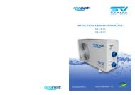
<strong>SV</strong> <strong>Series</strong> Spa Controls<br />
<strong>Install</strong>ation & Technical <strong>Manual</strong><br />
<strong>SV</strong>2 / <strong>SV</strong>2-VH / <strong>SV</strong>3 / <strong>SV</strong>3-VH / <strong>SV</strong>4-VH
Table of Contents<br />
SYSTEM OVERVIEW<br />
Safety Warnings ................................................................ 1<br />
Specification Sheet ............................................................ 2<br />
Component Overview ......................................................... 3<br />
Spa Pack Dimensions ......................................................... 4<br />
<strong>SV</strong>2.T Keypad Dimensions .................................................. 5<br />
<strong>SV</strong>3.T / <strong>SV</strong>4.T Keypad Dimensions ....................................... 6<br />
INSTALLATION PROCEDURES<br />
Floor mount spa pack installation ......................................... 7<br />
Wall mount spa pack installation .......................................... 8<br />
Keypad installation (all models) ........................................... 9<br />
Keypad cut-out template .................................................... 10<br />
Electrical Wiring (terminal block connections) ........................ 11<br />
Dip Switch settings ............................................................ 12<br />
Pump Configurations .......................................................... 13<br />
AMP Power Outlets (240V) .................................................. 14<br />
Low Voltage Outlets (12V) .................................................. 15<br />
Heat Pump <strong>Install</strong>ation ....................................................... 16<br />
OEM PROGRAMMABLE OPTIONS<br />
Program circuit breaker rating (current limit) ........................ 17<br />
OEM configuration menu .................................................... 18<br />
Diagnostics menu ............................................................. 23<br />
Contact Us ...................................................................... 24<br />
<strong>SV</strong> <strong>Series</strong> Spa Controls<br />
i
!<br />
WARNINGS<br />
Please read the following before installing or connecting this appliance<br />
RISK OF ELECTRICAL SHOCK<br />
All electrical connections must be performed by a licensed electrician and<br />
must confirm to all national, state and local electrical codes in effect at the<br />
time of installation.<br />
The appliance should be supplied through a residual current device (RCD)<br />
having a rated residual operating current not exceeding 30mA.<br />
The appliance must be connected to a suitable rated and weather protected<br />
power supply. The supply line should be a dedicated power circuit and<br />
means for disconnection must be incorporated in the fixed wiring in<br />
accordance with your local wiring regulations. Means for disconnection from<br />
the supply mains should have a contact separation in all poles that provide<br />
full disconnection under over voltage Category III conditions.<br />
Earthed appliances must be permanently connected to fixed wiring<br />
(European models only).<br />
The appliance contains no serviceable parts. Do not attempt service of this<br />
control pack. Contact your dealer or authorized service agent for assistance.<br />
Turn the mains power OFF before servicing appliance or modifying any cable<br />
connection<br />
Suitable for indoor use only or when installed under a weatherproof spa<br />
skirt. The appliance should be installed in an enclosure such that all<br />
electrical connections cannot be accessible to the user without the use of a<br />
tool.<br />
To prevent electric shock hazard and/or water damage to this appliance, all<br />
unused receptacles must have a water proof seal in place.<br />
Parts incorporating electrical components must be located or fixed so that<br />
they cannot fall into the bath or spa.<br />
Parts containing live parts, except parts supplied with safety extra-low<br />
voltage not exceeding 12V must be inaccessible to a person in the bath or<br />
spa.<br />
This appliance must not be installed in proximity to highly flammable materials.<br />
o<br />
Water temperature in excess of 38 C may cause hyperthermia (heat stress).<br />
It is the spa manufacturer's and/or installer's responsibility to select suitable<br />
loads and configure load shed settings (if required) to ensure the system<br />
does not exceed its rated maximum total load.<br />
It is the installer's responsibility to ensure the floor is capable of supporting<br />
the expected load of the bath or spa and an adequate drainage system has<br />
to be provided to deal with overflow water.<br />
A whirlpool spa should incorporate a water filtration system where the<br />
required level of water purity can be achieved.<br />
An adequate drainage system has to be provided if the equipment is to be<br />
installed in a pit.<br />
Low voltage or improper wiring may cause damage to this appliance. Read<br />
and follow all wiring instructions when connecting to power supply.<br />
Any damaged cable must be replaced immediately.<br />
<strong>SV</strong> <strong>Series</strong> Spa Controls<br />
1<br />
This appliance is not intended for use by persons (including children) with<br />
reduced physical, sensory or mental capabilities, or lack of experience and<br />
knowledge, unless they have been given supervision or instruction<br />
concerning use of the appliance by a person responsible for their safety.<br />
Children should be supervised to ensure that they do not play with the<br />
appliance.
<strong>SV</strong> <strong>Series</strong> Specifications<br />
Electrical Specifications<br />
Model No Max Maximum Multi Input Voltage Input Voltage Hz Heater Size<br />
Current Phase Current Single Phase* Three Phase*<br />
System Specifications<br />
All Models (<strong>SV</strong>2/<strong>SV</strong>3/<strong>SV</strong>2-VH/<strong>SV</strong>3-VH/<strong>SV</strong>4-VH)<br />
<strong>SV</strong>2 15A - 230-240V AC 400-415V AC 50/60 2kW<br />
<strong>SV</strong>3 45A - 230-240V AC 400-415V AC 50/60 3kW<br />
<strong>SV</strong>2-VH 15A 16A per phase 230-240V AC 400-415V AC 50/60 3kW Variable<br />
<strong>SV</strong>3-VH 45A 25A per phase 230-240V AC 400-415V AC 50/60 6kW Variable<br />
<strong>SV</strong>4-VH 60A 25A per phase 230-240V AC 400-415V AC 50/60 6kW Variable<br />
* Range of acceptability (+/-6%)<br />
Output Ratings<br />
Outlet Max Current Output Voltage Hz Typical Accessory<br />
Maximum Controlled Temperature<br />
Thermal Cut-Out<br />
Maximum Ambient Temperature<br />
Minimum Flow Rate<br />
RCD trip rating<br />
Weight (without cable)<br />
Dimensions (with couplings)<br />
Enclosure<br />
o<br />
41 C<br />
o<br />
o<br />
47 C +/-3 C<br />
o<br />
40 C<br />
65 L/min<br />
30mA<br />
5kg<br />
544x309x90mm<br />
IPx5<br />
Circ 2A 230-240V AC 50/60 Small Circulation Pump<br />
O3/UV 2A 230-240V AC 50/60 Ozone Generator / UV Sanitiser<br />
Blower 6.3A 230-240V AC 50/60 Air Blower<br />
Pump 1 12A 230-240V AC 50/60 2 Spd Jet Pump / 1 Spd Jet Pump<br />
Pump 2 12A 230-240V AC 50/60 1 Speed Jet Pump<br />
Mains 1 ^ 12A 230-240V AC 50/60 Mains power outlet (always on)<br />
Operating Temperature<br />
Storage Temperature<br />
Humidity<br />
o<br />
o<br />
0 C to 40 C<br />
o<br />
o<br />
-25 C to 85 C<br />
up to 85% RH<br />
(non condensing)<br />
Pump 3 * 12A 230-240V AC 50/60 2 Spd Jet Pump / 1 Spd Jet Pump<br />
Pump 4 # 12A 230-240V AC 50/60 1 Speed Jet Pump<br />
Mains 2 *^ 12A 230-240V AC 50/60 Mains power outlet (always on)<br />
~<br />
Light 1 1A 12V AC LED Light<br />
~<br />
Light 2 * 1A 12V AC LED Light<br />
* Outlets not available on <strong>SV</strong>2 / <strong>SV</strong>2-VH models<br />
# Outlet not available on <strong>SV</strong>2 / <strong>SV</strong>2-VH / <strong>SV</strong>3 / <strong>SV</strong>3-VH models<br />
^ Dedicated mains power outlets (always ON)<br />
~ 1A maximum current draw. This is split between keypads, expand ports and light sockets.<br />
Each socket is rated to 1A maximum so the full 1A can be drawn from a single socket if required.<br />
<strong>SV</strong> <strong>Series</strong> Spa Controls<br />
2
<strong>SV</strong> <strong>Series</strong> Overview<br />
Mains Power<br />
Terminal Block<br />
Heater Connection<br />
Terminal Block<br />
Fuse 1<br />
(Phase 3 Loads)<br />
Fuse 2<br />
(Phase 2 Loads)<br />
Fuse 3<br />
(Phase 1 Loads)<br />
Low Voltage Connections<br />
(12V)<br />
keypads, lights, in-pool sensor<br />
digital/analog expand ports<br />
Mains Power<br />
Cable Entry<br />
Points<br />
Heartbeat LED<br />
DIP Switch Bank<br />
Wall Mount Bracket<br />
Wall Mount<br />
Bracket<br />
AMP Power Outlets<br />
(230-240V AC)<br />
for spa accessories:<br />
circ, o 3/uv, air blower<br />
jet pumps, auxiliaries<br />
TM<br />
Coupling<br />
(tail & nut)<br />
Coupling<br />
(tail & nut)<br />
Mounting Foot<br />
Earth Bonding<br />
Terminal<br />
Heater Tube<br />
Heater Cover Plate<br />
(remove to access<br />
heater connections)<br />
<strong>SV</strong> <strong>Series</strong> Spa Controls<br />
3
TM<br />
Spa Pack Dimensions<br />
90.00 mm<br />
Front View<br />
448.90 mm<br />
4<br />
ADVANCED SPA CONTROL<br />
variable heater<br />
Side View<br />
309.00 mm<br />
6 mm<br />
147.86 mm<br />
Rear View<br />
448.90 mm<br />
18.50 mm<br />
544.00 mm<br />
Bottom View<br />
293.07 mm<br />
6 mm<br />
147.86 mm<br />
18.50 mm<br />
544.00 mm<br />
544.00 mm<br />
<strong>SV</strong> <strong>Series</strong> Spa Controls<br />
4
Keypad Dimensions<br />
165.00 mm<br />
<strong>SV</strong>2.T keypad<br />
2.75" (70mm) LCD Screen<br />
9 Keys<br />
Blue LED Backlighting<br />
94.00 mm<br />
165mm x 94mm x 33.50mm<br />
2.5m lead length<br />
<strong>SV</strong>-2T<br />
145.00 mm<br />
6.00 mm<br />
33.50 mm<br />
27.50 mm<br />
74.00 mm<br />
R 37mm<br />
71.00 mm<br />
<strong>SV</strong> <strong>Series</strong> Spa Controls 5
Keypad Dimensions<br />
185.00 mm<br />
<strong>SV</strong>3.T / <strong>SV</strong>4.T keypad<br />
3.5" (90mm) LCD screen<br />
12 keys<br />
100.00 mm<br />
RGB colour mixing LED backlighting<br />
185mm x 100mm x 33.50mm<br />
<strong>SV</strong>-3T<br />
2.5m lead length<br />
145.00 mm<br />
6.00 mm<br />
33.50 mm<br />
27.50 mm<br />
74.00 mm<br />
R 37mm<br />
71.00 mm<br />
<strong>SV</strong> <strong>Series</strong> Spa Controls 6
TM<br />
Spa Pack <strong>Install</strong>ation<br />
Floor mounting procedure<br />
4<br />
ADVANCED SPA CONTROL<br />
variable heater<br />
Due to its flexible design the spa pack can be installed on either the suction side or<br />
the discharge side of the filtration pump.<br />
Select a suitable location on the spa base and firmly secure spa pack to<br />
base using four (4) x screws of appropriate length backed with flat washers.<br />
Each screw should be positioned in the moulded cut outs of the mounting<br />
feet (refer above & aside). The spa pack should be fixed using ALL four<br />
screw locations to provide adequate support (two screws on each side of the<br />
spa pack).<br />
IMPORTANT NOTE<br />
The spa pack is NOT intended to be used outdoor. The spa pack must be installed in<br />
indoor environments only and should be installed in an enclosure so that all electrical<br />
connections cannot be accessible without the use of a tool (ie. under spa cabinet).<br />
NOTES<br />
Only use pan, round<br />
or truss head screws<br />
with flat washers<br />
DO NOT use countersunk<br />
screws. They may damage<br />
or crack the moulded<br />
mounting brackets<br />
The spa pack must be installed with the heater tube horizontal and should<br />
be positioned as low as possible in the pipe work of the spa.<br />
The spa pack can be plumbed for water flow in either direction however the<br />
most preferred direction is for water to flow from left to right.<br />
When constructing a spa care should be taken to minimise vibration from the<br />
pumps transferring to the spa pack through the base, frame or pipe work.<br />
Extended periods of vibration may lead to early component failure.<br />
The spa pack should be located at least 10cm (4") above potential flood<br />
level. If spa floor is on ground level the spa pack should be raised 10cm (4")<br />
above spa floor level.<br />
<strong>Install</strong> spa pack in a suitable position to prevent water dripping onto the<br />
unit. In particular avoid installing spa pack directly underneath keypad<br />
mounting location.<br />
<strong>SV</strong> <strong>Series</strong> Spa Controls<br />
7
TM<br />
Spa Pack <strong>Install</strong>ation<br />
Wall mounting procedure<br />
Due to its flexible design the spa pack can be installed on either the suction side or<br />
the discharge side of the filtration pump.<br />
Select a suitable location under the spa and use two (2) x (2x4)” treated<br />
timber beams or other suitable timber or metal materials to construct an<br />
adequate support structure to mount the spa pack to.<br />
The mounting support frame should be capable of supporting the weight of<br />
the spa pack and should withstand the force of the pipe work moving each<br />
time the filtration pump starts or stops.<br />
4<br />
ADVANCED SPA CONTROL<br />
variable heater<br />
Firmly secure spa pack to support frame using ALL four (4) x screw hole<br />
locations provided on the moulded mounting brackets (refer aside)<br />
Only use pan, round or<br />
truss head screws / bolts<br />
backed with flat washers<br />
DO NOT use countersunk<br />
screws or bolts. They may<br />
damage or crack the moulded<br />
mounting brackets<br />
NOTES<br />
The spa pack must be installed with the heater tube horizontal and should<br />
be positioned as low as possible in the pipe work of the spa.<br />
The spa pack can be plumbed for water flow in either direction however the<br />
most preferred direction is for water to flow from left to right.<br />
When constructing a spa measures should be taken to minimise vibration<br />
from the pumps transferring to the spa pack through the base, frame or<br />
pipe work. Extended periods of vibration may lead to early component failure.<br />
IMPORTANT NOTE<br />
The spa pack is NOT intended to be used outdoor. The spa pack must be installed in<br />
indoor environments only and should be installed in an enclosure so that all electrical<br />
connections cannot be accessible without the use of a tool (ie. under spa cabinet).<br />
The spa pack should be located at least 10cm (4") above potential flood<br />
level. If spa floor is on ground level the spa pack should be raised 10cm (4")<br />
above spa floor level.<br />
<strong>Install</strong> spa pack in a suitable position to prevent water dripping onto the<br />
unit. In particular avoid installing spa pack directly underneath keypad<br />
mounting location.<br />
<strong>SV</strong> <strong>Series</strong> Spa Controls<br />
8
Keypad <strong>Install</strong>ation<br />
All Models (<strong>SV</strong>2.T / <strong>SV</strong>3.T / <strong>SV</strong>4.T)<br />
Centre to Centre<br />
71.00 mm<br />
<strong>SV</strong>2.T<br />
Select a suitable keypad location that is above maximum water level and that<br />
is easily accessible to the spa user.<br />
Before drilling the cut out for the keypad, hold the keypad in place and check<br />
there is sufficient cable length to reach the spa pack without the cable being<br />
stretched or pulled against sharp edges.<br />
Drill two 76mm diameter holes spaced 71mm apart from centre to centre (as<br />
illustrated aside).<br />
Cut out the residual material between the two holes (as illustrated).<br />
Clean mounting surface to be free of dirt and dust particles, oil and grease.<br />
To ensure the keypad adhesive bonds to the spa well the shell must have a<br />
clean, smooth and dry surface.<br />
Peel paper backing from adhesive gasket ensuring all of the adhesive is<br />
exposed.<br />
76 mm<br />
76 mm<br />
Feed cable through opening, align keypad and press firmly onto mounting<br />
surface. Ensure keypad is adhered well to surface by pressing evenly around<br />
the outside edge of the whole keypad.<br />
IMPORTANT NOTES<br />
<strong>SV</strong>3.T / <strong>SV</strong>4.T<br />
The keypad mounting location should have adequate drainage to prevent<br />
accumulation of water on or around the keypad area.<br />
If keypad is to be mounted under a spa cover allow sufficient clearance to<br />
prevent cover resting directly on keypad.<br />
Parts incorporating electrical components (ie. keypads) must be fixed so that<br />
they cannot fall into the bath or spa<br />
KEYPAD CABLE CONNECTION<br />
76 mm<br />
Unscrew and remove low voltage<br />
connections cover from spa pack<br />
enclosure<br />
Connect keypad RJ45 plug into either<br />
TPAD1 or TPAD2 socket<br />
147 mm<br />
Drip Loop<br />
Route the keypad cable through the cable<br />
guide provided<br />
Ensure the keypad cable has a drip loop<br />
before it enters the enclosure<br />
<strong>SV</strong> <strong>Series</strong> Spa Controls<br />
9
<strong>SV</strong>T Keypad Cut Out Template<br />
<strong>SV</strong>2.T / <strong>SV</strong>3.T / <strong>SV</strong>4.T (Scale 1:1)<br />
NOTE: To print in 1:1 scale, set Page Scaling to NONE in the print dialog box<br />
Centre to Centre<br />
71.00 mm<br />
1 Drill both holes<br />
2<br />
with 76mm<br />
Hole Saw<br />
After drilling both holes<br />
remove this material<br />
from both sides<br />
76 mm<br />
76 mm<br />
<strong>SV</strong> <strong>Series</strong> Spa Controls<br />
10
Electrical Wiring (Terminal Block Connections)<br />
AUS / NZ / European Models (230-240V AC)<br />
Tools Required: Wire Strippers, Phillips head screwdriver, flat head screwdriver<br />
Remove five (5) x Phillips screws from mains lid to access terminal block.<br />
Cut away appropriate length of outer insulation from mains power cable and<br />
strip away 25mm (1") of wire insulation from the end of each wire.<br />
Route mains cable through one of the two snap out holes provided and<br />
secure the cable with a gland to provide adequate cable strain relief<br />
(Tighten gland with use of a tool to ensure supply line anchorage point<br />
cannot be removed by hand).<br />
.<br />
Push the wires into the correct terminals as labelled. Refer wiring guide below<br />
or on the sticker inside the terminal block area.<br />
Tighten all screws on the terminal block with a screwdriver and check to<br />
ensure each wire has been firmly secured. Then screw mains lid back on.<br />
WARNING<br />
This appliance must be supplied through a residual current device<br />
(RCD) having a rated residual operating current not exceeding 30mA.<br />
Correct wiring of the main electricity board, RCD and spa pack is critical.<br />
When installing appliance refer to your local wiring regulations.<br />
When installing mains power cable providing service loops (additional wire<br />
length for future serviceability) to incoming wiring is recommended.<br />
P3<br />
P2<br />
CS<br />
P1<br />
G<br />
N<br />
P3<br />
P2<br />
CS<br />
P1<br />
G<br />
N<br />
P3<br />
P2<br />
CS<br />
P1<br />
G<br />
N<br />
230-240V (3 wire) single phase<br />
230-240V (4 wire) dual phase<br />
230-240V (5 wire) three phase<br />
Terminal<br />
Wiring<br />
Terminal<br />
Wiring<br />
Terminal<br />
Wiring<br />
P3<br />
P2<br />
CS<br />
P1<br />
G<br />
N<br />
Link to CS<br />
Link to CS<br />
Link to P3 and P2<br />
Phase<br />
Earth<br />
Neutral<br />
P3<br />
Link to CS<br />
P2 Phase 2<br />
CS<br />
Link to P3<br />
P1 Phase 1<br />
G<br />
Earth<br />
N<br />
Neutral<br />
P3 Phase 3<br />
P2 Phase 2<br />
CS<br />
Not used<br />
P1 Phase 1<br />
G<br />
Earth<br />
N<br />
Neutral<br />
*Dip Switch 5<br />
*Dip Switch 6<br />
OFF<br />
OFF<br />
*Dip Switch 5<br />
*Dip Switch 6<br />
ON<br />
OFF<br />
*Dip Switch 5<br />
*Dip Switch 6<br />
ON<br />
ON<br />
* Refer Dip switch information on page 11<br />
<strong>SV</strong> <strong>Series</strong> Spa Controls<br />
11
DIP Switch Settings<br />
System Configuration<br />
Basic spa configuration is achieved by setting dip switches. The dip switches determine pump<br />
configuration and select the number of input phases wired to the spa pack. The installer must<br />
correctly configure the dip switches to match the pump and power configuration connected to<br />
the spa pack.<br />
The dip switch bank (illustrated aside) has six individual switches. Switches set to the top of<br />
the switch bank are in the ON position. Switches set to the bottom of the switch bank (closest<br />
to the numbers) are in the OFF position. Refer to tables below for dip switch settings:<br />
SW Setting OFF ON Notes<br />
<strong>SV</strong>2 / <strong>SV</strong>4 Models<br />
1 Circ Fitted Not Fitted Fitted<br />
2 Pump 1 Type Single Speed Two Speed If set to ‘OFF’ pump2 assumed fitted<br />
3 Pump 3 Type Single Speed Two Speed Not used on <strong>SV</strong>2/<strong>SV</strong>2-VH models<br />
4 Pump 4 Fitted Not Fitted Fitted Not used on <strong>SV</strong>2/<strong>SV</strong>2-VH models<br />
5 Phase Selection Single Phase 2/3 Phase If set to ‘ON’ dip switch 6 is enabled<br />
6 Multi Phase Two Phase Three Phase<br />
SW Setting OFF ON Notes<br />
<strong>SV</strong>3 Models<br />
Heartbeat LED<br />
1 Circ Fitted Not Fitted Fitted<br />
2 Pump 1 Type Single Speed Two Speed If set to ‘OFF’ pump2 assumed fitted<br />
3 Pump 3 Fitted Not Fitted Fitted<br />
4 Not Used - -<br />
5 Phase Selection Single Phase 2/3 Phase If set to ‘ON’ dip switch 6 is enabled<br />
6 Multi Phase Two Phase Three Phase<br />
Heartbeat LED<br />
Dip Switch Bank<br />
All <strong>SV</strong> model spa packs feature a heartbeat LED. The heartbeat LED flashes to indicate the<br />
current health/status of the spa pack. When the spa pack is functioning correctly with no<br />
errors to report the heartbeat LED emits a single flash in a constant pulse much like a<br />
heartbeat (ON, OFF, ON, OFF).<br />
If the spa pack encounters a fault the heartbeat LED will begin flashing in sequence with the<br />
error code number being experienced (ie. ER2 = ON,ON; OFF ON,ON; OFF).<br />
The heartbeat LED is located beside the bottom left hand corner of the dip switch bank and will<br />
emit its red flash through the tinted low voltage connection cover, making it clearly visible from<br />
the front of the spa pack.<br />
<strong>SV</strong> <strong>Series</strong> Spa Controls<br />
12
Pump Configurations<br />
System Configuration Reference Table<br />
notes n/a = not available If pump1 = 2 spd, the pump 2 outlet socket cannot be used<br />
If pump3 = 2 spd, the pump 4 outlet socket cannot be used<br />
<strong>SV</strong> <strong>Series</strong> Spa Controls<br />
13
AMP Power Outlets<br />
230-240V AC Output<br />
Multiple power output sockets are provided to run spa accessories. Each output<br />
socket is clearly labelled including the maximum current for that outlet. In addition<br />
the maximum current per phase is labelled. When connecting accessories the<br />
installer must consider the current draw of each appliance to be connected and<br />
ensure the system does not exceed the maximum load limits.<br />
The output sockets are wired with three sockets per phase (refer table below). The<br />
only exception is phase 1 which also powers the heater element (a socket is not<br />
provided, the heater is wired internally). Each phase circuit is protected by a fuse.<br />
AMP Power Outlets<br />
The sum total current draw of all appliances connected to a phase should not<br />
exceed the maximum current limit of that respective phase. Refer to ratings<br />
information labels on spa pack for current limits.<br />
In single phase applications the outlet sockets are still governed by the<br />
fuse/current limit of each phase. The power outlet arrangement is as follows:<br />
PHASE 1 PHASE 2 PHASE 3<br />
Securing Lugs<br />
Locking Tabs<br />
circulation pump pump 1 pump 3<br />
sanitiser (ozone/uv) pump 2 pump 4<br />
blower mains* mains*<br />
heater#<br />
Plug Overmould<br />
* Dedicated 230-240V power outlets (always on)<br />
# Heater is connected internally to phase 1. Consider when calculating total current draw of phase 1<br />
AMP Sockets & Plugs<br />
<strong>SV</strong> series spa packs utilise AMP mate-N-lok power connectors. The AMP connectors<br />
feature a key pattern for fail safe one way connection. When connecting accessory<br />
devices be sure to push cordset firmly into socket and ensure both side locking taps<br />
have been secured and latched in place (refer illustrations aside).<br />
AMP Outlets Cover<br />
Firmly secured and<br />
latched in place<br />
AMP Outlets Cover<br />
12<br />
For installations where there is insufficient<br />
depth under the spa skirt for the cable radius of<br />
an over moulded plug the installer can opt to fit<br />
the amp outlet cover and use non over moulded<br />
plugs to achieve a tighter cable radius.<br />
If accessories are connected with non over<br />
moulded AMP plugs the AMP outlet cover<br />
MUST be installed and fixed with screws.<br />
to<br />
The AMP outlet cover features snap out sections<br />
to be cut away at point of install to suit quantity<br />
of cords in use.<br />
<strong>SV</strong> <strong>Series</strong> Spa Controls<br />
14
Low Voltage Connections<br />
12V AC<br />
The low voltage connections are located on the top right hand corner of the spa<br />
pack. RJ45/RJ12 sockets are used for connection and are located inside the spa<br />
pack enclosure. The low voltage connections cover must be fitted and secured with<br />
screws for water proofing seal to work.<br />
Low Voltage<br />
Connections<br />
Cable guide holes<br />
used to route<br />
cables and form<br />
water proof seal<br />
The <strong>SV</strong> controllers feature the following low voltage connections:<br />
Socket Accessory<br />
TPAD1 Keypad #1<br />
TPAD2* Keypad #2<br />
IPTS<br />
In pool temperature sensor<br />
EXPAND1 Digital expansion port<br />
EXPAND2 Analogue expansion port<br />
LIGHT1 LED Light Output<br />
LIGHT2* LED Light Output<br />
* Sockets not available on <strong>SV</strong>2/<strong>SV</strong>2-VH models<br />
Drip Loop<br />
IMPORTANT NOTES<br />
1A maximum 12V current draw. This is split between keypads, expand ports<br />
and lights. Each socket is rated to 1A maximum so the full 1A can be drawn<br />
from a single socket if required.<br />
Ensure each low voltage cable is routed through the cable guide hole on the<br />
side of the spa pack and allow for drip loops before entry to the enclosure.<br />
Port current sensing<br />
in pool temperature sensor<br />
The <strong>SV</strong> series spa packs monitor the RMS current drawn from the low voltage<br />
ports at all times. 12V current drawn by keypads, in pool temp sensors, expand<br />
ports and lights are measured. If the current is above 1.1A the controller will<br />
shut down and latch fault code (Er6 - 12V overload).<br />
Digital expand port<br />
A PC communications and general purpose digital interface port. Most suited to<br />
interfacing to other digital equipment such as stereos, remote controls etc<br />
Analog expand port<br />
colour LED spa light<br />
An analog expansion port that contains two analog inputs and a digital I2C bus.<br />
The I2C bus is shared with touch pad 1 port and allows connection of NXP I2C<br />
family of devices.<br />
<strong>SV</strong> <strong>Series</strong> Spa Controls<br />
15
Heat Pump <strong>Install</strong>ation<br />
How to connect a heat pump to a <strong>SV</strong>x-VH controller<br />
All variable heater models of the <strong>SV</strong> <strong>Series</strong> spa controllers have the capability to<br />
seamlessly integrate and control a heat pump for efficient heating and cooling of<br />
the spa water. Not all heat pumps can be connected to an <strong>SV</strong> controller. Only a<br />
SpaNET approved heat pump fitted with a SpaNET heat pump expansion module<br />
can be used.<br />
If connected the <strong>SV</strong> controller will automatically detect the heat pump and take<br />
control of its operation. All heat pump functions including heating / cooling /<br />
temperature adjustment / defrost cycles / over temp protection / diagnostics and<br />
monitoring are all controlled by the <strong>SV</strong> spa controller and the <strong>SV</strong> spa side touch<br />
pad.<br />
IMPORTANT NOTES<br />
Not all heat pumps can be connected to an <strong>SV</strong> controller. Only a SpaNET<br />
approved heat pump fitted with a SpaNET heat pump expansion module can<br />
be used.<br />
If the ambient temperature is below the operational limit of the heat pump<br />
(-10 'C) the <strong>SV</strong> heater element will be enabled regardless of the H.ELE setting,<br />
and the heat pump is disabled.<br />
HEAT PUMP CONNECTION<br />
Connect power to the heat pump from either:<br />
a) a dedicated 230V mains outlet on the <strong>SV</strong> controller itself<br />
Note: Check ratings information of heat pump to be connected and<br />
ensure maximum current limit for the <strong>SV</strong> mains outlet is not exceeded<br />
b) a suitably rated and protected power supply<br />
The heat pump should be plumbed in-line before the <strong>SV</strong> controller so that<br />
water flows from the heat pump through the <strong>SV</strong> controller and then returns<br />
into the spa pool.<br />
If H.ELE is set to ON the <strong>SV</strong> heater element will operate in conjunction with the<br />
heat pump to boost heating only if the water temperature is 2'C or more below<br />
the set temperature point or the heat pump has been operating for more than<br />
1 hour and the set temperature point has not been reached.<br />
A defrost cycle will run for a minimum of 3 minutes and a maximum of 10<br />
minutes<br />
If the heat pump being used is fitted with a flow switch, the flow switch must<br />
close within 30 seconds of filtration pump operation otherwise a flow error will<br />
occur<br />
The heat pump MUST be installed according to the air space requirements<br />
detailed in the <strong>SV</strong> <strong>Series</strong> Heat Pump <strong>Install</strong>ation <strong>Manual</strong>. Failure to do so will<br />
void heat pump warranty.<br />
Connect the heat pump data cable into the Expand2 (EXP2) data socket of<br />
the <strong>SV</strong> controller<br />
Finally configure the H.PMP (heat pump operating mode) and<br />
H.ELE (<strong>SV</strong> element boost) SETUP menu options to your desired specification<br />
(refer Setup menu section of <strong>SV</strong> <strong>Series</strong> User <strong>Manual</strong>)<br />
<strong>SV</strong> <strong>Series</strong> Spa Controls<br />
16
Program Circuit Breaker Rating<br />
For variable element operation<br />
Press & hold +<br />
Current sensing<br />
Each “VH” (variable heater) model of <strong>SV</strong> controller contains mains current<br />
measurement hardware that allows the controller to monitor the RMS current draw.<br />
The current sensing hardware is only installed on Phase 1. Phases 2 and 3 can also<br />
be monitored if they are wired to terminal “CS” of the mains terminal block (refer<br />
wiring information on page 10).<br />
°C<br />
°F MODE<br />
SPD<br />
BRT<br />
OFF<br />
ON<br />
AM<br />
PM<br />
31 A<br />
AM<br />
°C<br />
1 0:<br />
3 0 3 8.0<br />
PM<br />
°F<br />
SA SU MO TU WE TH FR SET TEMP<br />
SET TEMP<br />
°C<br />
°F<br />
MODE<br />
SPD<br />
BRT<br />
Press<br />
°F MODE<br />
SPD<br />
BRT<br />
OFF<br />
ON<br />
AM<br />
PM<br />
°C<br />
°C<br />
°F MODE<br />
SPD<br />
BRT<br />
OFF<br />
ON<br />
C.LMT<br />
°C<br />
°F<br />
BRT<br />
AM<br />
°C<br />
1 0:<br />
3 0 3 8.0<br />
PM<br />
°F<br />
SA SU MO TU WE TH FR SET TEMP<br />
AM<br />
PM<br />
SET TEMP<br />
MODE<br />
SPD<br />
to enter adjustment<br />
32 A<br />
AM<br />
°C<br />
1 0:<br />
3 0 3 8.0<br />
PM<br />
°F<br />
SA SU MO TU WE TH FR SET TEMP<br />
SET TEMP<br />
°C<br />
°F<br />
MODE<br />
SPD<br />
BRT<br />
°C<br />
°F MODE<br />
SPD<br />
BRT<br />
OFF<br />
ON<br />
AM<br />
PM<br />
33 A<br />
AM<br />
°C<br />
1 0:<br />
3 0 3 8.0<br />
PM<br />
°F<br />
SA SU MO TU WE TH FR SET TEMP<br />
SET TEMP<br />
°C<br />
°F<br />
MODE<br />
SPD<br />
BRT<br />
Current measurement is used for variable element operation. The purpose is to<br />
automatically adjust heater power level to match the residual current available<br />
when accessory devices (ie pumps and/or blower) are operating. The aim is to<br />
maximise heating input whilst spa is in use, but still remain within the current limit<br />
of the controller.<br />
The OEM menu item C.LMT (current limit) should be set to match the rating<br />
of the circuit breaker that feeds the spa pool. In multi phase installations<br />
the C.LMT should be set to match the current limit of Phase 1. To take full<br />
advantage of the variable element and maximise heater power level when spa in<br />
manual use the circuit breaker rating must be programmed correctly.<br />
Press<br />
to confirm & save<br />
The <strong>SV</strong> controller will shut down and latch fault code (Er10 - over current) if the <strong>SV</strong><br />
controller detects a mains current above 110% of C.LMT. The actual current draw of<br />
the spa controller can be viewed at anytime via the diagnostics menu or by using<br />
the SpaNET Link PC application. The default current limit (C.LMT) values for each<br />
model are as follows:<br />
IMPORTANT NOTES<br />
The installer must program the C.LMT (current limit) setting to match<br />
the rating of the circuit breaker that feeds the spa pool or for multiphase<br />
installs the rating of the current limit of Phase 1.<br />
The C.LMT (current limit) setting is stored in non volatile memory<br />
(EEPROM) so it is remembered when power is turned off. The C.LMT<br />
setting only needs to be programmed once.<br />
(Note: C.LMT value is NOT adjusted by EEPROM reset)<br />
If the C.LMT (current limit) setting is not matched to the circuit breaker<br />
rating correctly the spa owner may experience either tripping circuit<br />
breakers or “Er10 Over Current” latching errors.<br />
Model Default C.LMT<br />
<strong>SV</strong>2-VH 15 amp<br />
<strong>SV</strong>3-VH 32 amp<br />
<strong>SV</strong>4-VH 40 amp<br />
How to program the current limit (C.LMT) :<br />
Press and hold and buttons together until C.LMT is displayed<br />
Press<br />
button to enter current limit (C.LMT) adjustment<br />
Press or to adjust current limit to match circuit breaker rating<br />
Press<br />
button to confirm and save setting<br />
<strong>SV</strong> <strong>Series</strong> Spa Controls<br />
17
SA SU MO TU WE TH FR<br />
OEM Configuration Menu<br />
Access via keypad<br />
The <strong>SV</strong> controllers feature a hidden OEM configuration menu which allows complete customisation<br />
of the spa controller. Menu item options are detailed in the list below.<br />
To enter menu press and hold and buttons until [C.LMT] is displayed<br />
Press or to navigate through menu item list<br />
Press to enter menu item adjustment<br />
Press & hold +<br />
Press or to adjust setting<br />
Press<br />
to confirm setting and exit menu<br />
°C<br />
°F MODE<br />
SPD<br />
BRT<br />
OFF<br />
ON<br />
°C<br />
°F MODE<br />
SPD<br />
BRT<br />
OFF<br />
ON<br />
EXIT<br />
AM<br />
°C<br />
1 0:<br />
3 0 3 8.0<br />
PM<br />
°F<br />
SA SU MO TU WE TH FR SET TEMP<br />
AM<br />
PM<br />
AM<br />
PM<br />
SET TEMP<br />
31 A<br />
AM<br />
°C<br />
1 0:<br />
3 0 3 8.0<br />
PM<br />
°F<br />
SA SU MO TU WE TH FR SET TEMP<br />
SET TEMP<br />
°C<br />
°F<br />
MODE<br />
SPD<br />
BRT<br />
°C<br />
°F<br />
MODE<br />
SPD<br />
BRT<br />
Press<br />
Press<br />
IMPORTANT NOTES<br />
<strong>SV</strong> <strong>Series</strong> Spa Controls<br />
°F MODE<br />
SPD<br />
BRT<br />
OFF<br />
ON<br />
AM<br />
PM<br />
°C<br />
°C<br />
°F MODE<br />
SPD<br />
BRT<br />
OFF<br />
ON<br />
C.LMT<br />
°C<br />
°F<br />
BRT<br />
AM<br />
°C<br />
1 0:<br />
3 0 3 8.0<br />
PM<br />
°F<br />
SA SU MO TU WE TH FR SET TEMP<br />
AM<br />
PM<br />
SET TEMP<br />
to enter adjustment<br />
to confirm & save<br />
°F MODE<br />
SPD<br />
BRT<br />
OFF<br />
ON<br />
AM<br />
PM<br />
°C<br />
L.SHD<br />
°C<br />
°F<br />
BRT<br />
AM<br />
°C<br />
1 0:<br />
3 0 3 8.0<br />
PM<br />
°F<br />
SET TEMP<br />
The OEM menu item settings are stored in non volatile memory<br />
(EEPROM) and are remembered when power is turned off. No<br />
need to reprogram settings when power is restored.<br />
During an EEPROM reset all menu items will be restored to the<br />
factory default settings except C.LMT/V.MAX/1.LLM/2.LLM/3.LLM.<br />
A ten (10) second idle menu time out period exists. If a button<br />
press is not detected for 10 seconds the menu will time out<br />
and the screen will return to the default display mode.<br />
MODE<br />
SPD<br />
32 A<br />
°C<br />
°F<br />
BRT<br />
AM<br />
°C<br />
1 0:<br />
3 0 3 8.0<br />
PM<br />
°F<br />
SA SU MO TU WE TH FR SET TEMP<br />
SET TEMP<br />
MODE<br />
SPD<br />
°C<br />
°F MODE<br />
SPD<br />
BRT<br />
OFF<br />
ON<br />
AM<br />
PM<br />
SET TEMP<br />
33 A<br />
AM<br />
°C<br />
1 0:<br />
3 0 3 8.0<br />
PM<br />
°F<br />
SA SU MO TU WE TH FR SET TEMP<br />
SET TEMP<br />
MODE<br />
SPD<br />
°C<br />
°F<br />
MODE<br />
SPD<br />
BRT<br />
Menu Item Setting Notes<br />
C.LMT Current Limit (circuit breaker rating) 10 to 60A<br />
L.SHD Load Shed Count 1 to 7<br />
SANI Sanitiser (o 3/uv) on with spa use on / off<br />
C.JET Circ pump on with jet pump operation on / off<br />
V.ELE Variable element on / off<br />
V.MAX Maximum variable element power 3A to 25A<br />
H.USE Heat pump operation when spa in use on / off<br />
1.LLM Phase 1 load limit 1 to 5<br />
2.LLM Phase 2 load limit 1 to 5 (item disappears if set to 1 phase)<br />
3.LLM Phase 3 load limit 1 to 5 (item disappears if set to 1 or 2 phase)<br />
o o<br />
UNIT Temperature format C or F<br />
o<br />
o<br />
A.HYS Adaptive hysteresis limit 0 to 20 C, 0.2 C increments (0=disabled)<br />
S 24 Sanitiser (o 3/uv) on 24 hrs on / off<br />
C 24 Circ pump on 24 hrs on / off<br />
CAL<br />
Calibration menu<br />
C.ZER Mains current zero push OK button to zero reading<br />
C.ADJ Mains current reading adjust with up/down buttons<br />
V.ADJ Mains voltage reading adjust with up/down buttons<br />
H.AMB<br />
H.CON<br />
EXIT<br />
SERT<br />
Heat pump ambient temp reading<br />
Heat pump condenser temp reading<br />
Exit calibration submenu<br />
Service timers menu<br />
1.SER Service timer 1 [service filters] 0 to 52 wks (0 wks = disabled)<br />
2.SER Service timer 2 [service 1] 0 to 52 wks (0 wks = disabled)<br />
3.SER Service timer 3 [service 2] 0 to 52 wks (0 wks = disabled)<br />
EXIT<br />
Exit service timers submenu<br />
D.FST Heat pump defrost calibration menu DO NOT adjust without advice from SpaNET<br />
EPRM Reset EEPROM values to factory default All values reset except C.LMT / x.LLM / V.MAX<br />
EXIT<br />
18<br />
Exit OEM configuration menu<br />
DO NOT adjust without advice from SpaNET<br />
DO NOT adjust without advice from SpaNET
OEM Configuration Menu<br />
Menu item details<br />
L.SHD<br />
Load Shed Count<br />
V.ELE<br />
Variable Element Operation<br />
This setting determines the load shed behaviour of the heating element or heat<br />
pump (if fitted). Load shedding is governed by the load shed count (1 to 7). Load<br />
shed count = number of loads required to be turned ON for the heater to load<br />
shed and turn OFF. The filtration pump is not counted as a load, the blower and<br />
all other pumps are.<br />
Example:<br />
Load Shed Count = 2<br />
When any two loads in addition to the filtration pump are turned ON the heater<br />
load sheds and turns OFF.<br />
The L.SHD setting ranges from 1 to 7.<br />
1 = maximum load shed (default)<br />
7 = load shed disabled<br />
SANI<br />
Sanitiser (o 3/uv) Operation<br />
Determines how the sanitiser power outlet operates during manual spa use.<br />
The setting choices are:<br />
ON<br />
OFF<br />
sanitiser ON with pool use<br />
sanitiser OFF with pool use (default)<br />
Variable element operation allows the <strong>SV</strong> controller to automatically adjust the<br />
heater power level to match the residual current available when accessory devices<br />
(ie pumps and/or blower) are operating. The benefit of this feature is the element<br />
can automatically reduce its power level and remain on instead of load shedding<br />
and turning off when spa is in manual use and jet pumps have been activated.<br />
The setting choices are:<br />
ON<br />
OFF<br />
variable element enabled (default)<br />
variable element disabled<br />
Note: If disabled the heating behaviour is the same as a standard element. Load<br />
shed settings may need to be configured to ensure the spa pack does not exceed<br />
its maximum current limit.<br />
V.MAX<br />
Maximum Variable Element Size<br />
If variable element operation is enabled the installer also has the ability to limit the<br />
maximum current the heating element draws (3A to 25A) via the V.MAX menu<br />
item. This enables the installer to reduce the heater current draw where available<br />
power is limited, without the need to replace the heater element or spa pack. It<br />
also allows for the heater to be returned to maximum current if more power<br />
became available.<br />
The V.MAX setting ranges from 3A to 25A<br />
Default setting = 23A<br />
C.JET<br />
Circ on with Jet Pump<br />
H.USE<br />
Heat Pump Operation (when spa pool is in use)<br />
Determines behaviour of circ pump when jet pump is turned on for manual spa<br />
use. The setting choices are:<br />
ON<br />
OFF<br />
circ pump forced ON with jet pump use<br />
circ pump controlled automatically (default)<br />
This setting determines whether the heat pump will operate if spa pool is in use.<br />
The benefit being that some spa owners may not wish to hear the noise of the<br />
heat pump running whilst they are using the spa. The setting choices are:<br />
ON<br />
OFF<br />
heat pump operation ENABLED whilst spa is in use (default)<br />
heat pump operation DISABLED whilst spa is in use<br />
<strong>SV</strong> <strong>Series</strong> Spa Controls<br />
19
OEM Configuration Menu<br />
Menu item details<br />
C 24<br />
Circ Pump (24 hours)<br />
x.LLM Load Limit Settings (Phases 1/2/3)<br />
This setting allows the installer to select the maximum number of loads (1-5)<br />
allowed to run at the one time. Different load limits can be set for each phase.<br />
1.LLM = Phase 1 Load Limit<br />
2.LLM = Phase 2 Load Limit<br />
3.LLM = Phase 3 Load Limit<br />
Example: 1.LLM = 2<br />
This will allow 2 x accessories (pump(s) and/or blower) to run at the one time,<br />
but as soon as you try and turn the 3rd accessory on the button will not work<br />
until you turn one of the other accessories off first. Only 2 x loads will ever be<br />
allowed to run at the one time.<br />
UNIT<br />
Temperature Format<br />
Used to select desired temperature format<br />
A.HYS<br />
Adaptive Hysteresis (Dynamic Thermal Tuning)<br />
The <strong>SV</strong> controllers feature adaptive hysteresis for heat control to reduce demand<br />
heating cycling. Adaptive hysteresis control tunes the temperature sensing to<br />
that particular spa pool and environment. It is particularly advantageous when in<br />
heater temperature sensing is employed. The A.HYS menu item allows the<br />
installer to set the maximum range that the hysteresis can be adjusted.<br />
o<br />
The A.HYS setting ranges from 0 to 20 C<br />
A value of 0 disables adaptive hysteresis<br />
o<br />
Default = 20 C<br />
S 24<br />
Sanitiser (24 hours)<br />
The setting allows the sanitiser power outlet to be powered ON 24 hours per day<br />
The setting choices are:<br />
ON<br />
OFF<br />
o o<br />
C or F<br />
sanitiser power outlet always ON<br />
sanitiser power outlet automatically controlled (default)<br />
The setting enables the circ pump outlet to be powered ON 24 hours per day<br />
The setting choices are:<br />
ON<br />
OFF<br />
CAL<br />
circ pump power outlet always ON<br />
circ pump power outlet automatically controlled (default)<br />
Calibration Submenu<br />
Every <strong>SV</strong> controller is calibrated for mains voltage and current measurement<br />
during production. However, should the <strong>SV</strong> controller readings not agree with a<br />
true RMS multi meter reading they can be adjusted.<br />
The “CAL” sub menu offers the following options:<br />
C.ZER Mains current zero push OK button to zero reading<br />
C.ADJ Mains current reading adjust with up/down buttons<br />
V.ADJ Mains voltage reading adjust with up/down buttons<br />
EXIT<br />
V.ADJ<br />
C.ADJ<br />
Exit calibration submenu<br />
Field adjustment of the voltage reading should follow the following<br />
procedure:<br />
1) Measure the mains voltage using a true RMS multi meter.<br />
2) Adjust the voltage reading using V.ADJ to match the multi meter.<br />
Field calibration of the current reading should follow the following<br />
procedure:<br />
1) Stop any current draw by disconnecting any fixed 230V loads and<br />
switching off heating, pumps, blower etc<br />
2) Zero the current reading using C.ZER.<br />
3) Apply maximum pump loads and measure the current draw using a<br />
true RMS multi meter.<br />
4) Adjust current reading using C.ADJ to match multi meter reading.<br />
The <strong>SV</strong> measures the mains current that flows from “Phase 1” terminal to phase 1<br />
loads (heater, blower, ozone, circ). Any other loads connected via the CS terminal<br />
are also measured.<br />
<strong>SV</strong> <strong>Series</strong> Spa Controls<br />
20
OEM Configuration Menu<br />
Menu item details<br />
CAL<br />
Calibration Submenu (continued)<br />
x.SER<br />
Service Timers<br />
In spa configurations where a heat pump is installed the Calibration “CAL” sub<br />
menu will offer a further two options:<br />
H.AMB Heat pump ambient temp reading adjust with up/down buttons<br />
H.CON Heat pump condenser temp reading adjust with up/down buttons<br />
H.AMB<br />
Field adjustment of the heat pump ambient temperature reading should<br />
follow the following procedure:<br />
1) Measure the ambient temperature around the heat pump external<br />
ambient thermistor using a true RMS multi meter thermistor.<br />
2) Adjust the temperature reading using H.AMB to match the multi<br />
meter reading.<br />
These settings are used to enable and adjust service timers.<br />
A value of 0 results in the timer being disabled.<br />
Maximum timer value is 52 weeks.<br />
Independent counters are stored in RAM and therefore reset to 0 at power up.<br />
Counters for each service timer are incremented everyday at 8am. When the<br />
counter is greater or equal to the service timer value x 7, the touch pad will beep<br />
and scroll a message twice every 60 seconds.<br />
1.SER message = "SERVICE FILTERS"<br />
2.SER message = "SERVICE 2"<br />
3.SER message = "SERVICE 3"<br />
The particular counter is reset by pressing the OK button whilst the service<br />
message is scrolling.<br />
H.CON<br />
NOTE:<br />
Field adjustment of the heat pump condenser temperature reading<br />
should follow the following procedure:<br />
1) Remove the heat pump external cabinet to gain access to the area<br />
where the condenser thermistor is located.<br />
2) Measure the temperature of the heat pump condenser at the point<br />
where the heat pump condenser thermistor is located using a true<br />
RMS multi meter thermistor.<br />
2) Adjust the temperature reading using H.CON to match the multi<br />
meter reading.<br />
All <strong>SV</strong> controllers and <strong>SV</strong> series heat pumps are shipped precalibrated.<br />
DO NOT adjust the H.AMB or H.CON settings unless<br />
specifically directed to by SpaNET.<br />
The x.SER setting ranges from 0 to 52 weeks.<br />
Default Values:<br />
1.SER [SERVICE FILTERS] = 2 weeks<br />
2.SER [SERVICE 2] = 0 weeks (disabled)<br />
3.SER [SERVICE 3] = 0 weeks (disabled)<br />
D.FST<br />
Heat Pump Defrost Calibration Submenu<br />
These settings allow adjustment of various heat pump defrost parameters. All<br />
settings are pre-configured by SpaNET during production and should NOT<br />
be adjusted unless specifically directed to by SpaNET. Incorrect calibration<br />
could cause the heat pump to malfunction in cold conditions and this may void<br />
your product warranty. DO NOT ADJUST.<br />
<strong>SV</strong> <strong>Series</strong> Spa Controls<br />
21
OEM Configuration Menu<br />
Menu item details<br />
EPRM<br />
EEPROM Reset<br />
Use this feature to reset all OEM menu and User menu items back to their default<br />
values. All values will be reset to their default setting except:<br />
C.LMT / V.MAX / 1.LLM / 2.LLM / 3.LLM<br />
The above values are NOT reset because they will have been customised to suit the<br />
particular spa pool and its available power supply by the spa manufacturer or<br />
installing electrician.<br />
EXIT<br />
Exit OEM Menu<br />
<strong>SV</strong> <strong>Series</strong> Spa Controls<br />
22
Diagnostics Menu<br />
Access via keypad<br />
The <strong>SV</strong> controllers feature a hidden diagnostics menu which allows the installer / spa user<br />
to view onboard diagnostics and historical details about the spa controller. Menu item<br />
options are detailed in the list below.<br />
I<br />
To enter menu press and hold and and buttons<br />
Press or to navigate through menu item list<br />
Press to view diagnostic information on the selected item<br />
°C<br />
°F MODE<br />
SPD<br />
BRT<br />
OFF<br />
ON<br />
AM<br />
PM<br />
EXIT<br />
AM<br />
°C<br />
1 0:<br />
3 0 3 8.0<br />
PM<br />
°F<br />
SA SU MO TU WE TH FR SET TEMP<br />
SET TEMP<br />
°C<br />
°F<br />
MODE<br />
SPD<br />
BRT<br />
Press & hold + +<br />
I<br />
Press<br />
°F MODE<br />
SPD<br />
BRT<br />
IMPORTANT NOTE<br />
OFF<br />
ON<br />
AM<br />
PM<br />
°C<br />
WARN<br />
°C<br />
°F<br />
BRT<br />
AM<br />
°C<br />
1 0:<br />
3 0 3 8.0<br />
PM<br />
°F<br />
SA SU MO TU WE TH FR SET TEMP<br />
A ten (10) second idle menu time out period exists. If a<br />
button press is not detected for 10 seconds the menu will<br />
time out and the screen will return to the default<br />
temperature display mode.<br />
SET TEMP<br />
MODE<br />
SPD<br />
to view diagnostic information<br />
°F MODE<br />
SPD<br />
BRT<br />
OFF<br />
ON<br />
AM<br />
PM<br />
°C<br />
S.DAT<br />
°C<br />
°F<br />
BRT<br />
AM<br />
°C<br />
1 0:<br />
3 0 3 8.0<br />
PM<br />
°F<br />
SA SU MO TU WE TH FR SET TEMP<br />
SET TEMP<br />
MODE<br />
SPD<br />
Menu Item Setting Notes<br />
WARN Warnings scroll IPTS presence, W8, mode, Vmax/Vmin<br />
S.DAT State date scroll Date displayed in DD - MM - YY<br />
S.VER<br />
TYPE<br />
PUMP<br />
Software version scroll<br />
Controller type scroll<br />
Pump selection scroll<br />
LIMS Limits scroll Refer table below for further Limits details<br />
IPTS Current IPTS reading If IPTS not fitted, display will show 9997<br />
H.TMP<br />
C.TMP<br />
AMPS<br />
VOLT<br />
Current heater temperature reading<br />
Current case temperature<br />
Current mains current draw<br />
Current mains voltage<br />
V.ELE Current variable element power level 0 to 100%<br />
H.AMB<br />
H.CON<br />
EXIT<br />
Heat pump ambient temperature<br />
Heat pump condensor temperature<br />
Exit menu<br />
The limits scroll provides a scrolling list of all current, phase and load limit settings as<br />
programmed in the OEM menu or set by dip switches. This feature is a quick way to verify<br />
controller settings. The list of items that will be displayed are:<br />
C.LMT Current limit setting (10 to 60A)<br />
L.SHD Load shed count (1 to 7)<br />
PHSE<br />
Phase configuration (1,2 or 3 phase)<br />
1.LLM Phase 1 load limit (1 to 5)<br />
2.LLM Phase 2 load limit (1 to 5)<br />
3.LLM Phase 3 load limit (1 to 5)<br />
P.HYS<br />
H.HYS<br />
Current pool temperature sensor adaptive hysteresis value (0-200; where 1 = 0.1'C)<br />
Current heater temperature sensor adaptive hysteresis value (0-200; where 1 = 0.1'C)<br />
<strong>SV</strong> <strong>Series</strong> Spa Controls<br />
23
Contact Us<br />
Spa Net Pty Ltd<br />
Unit 4<br />
103 Railway Road North<br />
Mulgrave NSW 2756<br />
Australia<br />
Phone: +61 2 4587 7766<br />
Fax: +61 2 4587 8766<br />
www.spanet.com.au<br />
service@spanet.com.au<br />
accounts@spanet.com.au<br />
sales@spanet.com.au<br />
Technical Support & Service<br />
Accounts Department<br />
Sales Department<br />
<strong>SV</strong> <strong>Series</strong> Spa Controls<br />
24