83-919-000 - Wilkerson Corporation
83-919-000 - Wilkerson Corporation
83-919-000 - Wilkerson Corporation

You also want an ePaper? Increase the reach of your titles
YUMPU automatically turns print PDFs into web optimized ePapers that Google loves.
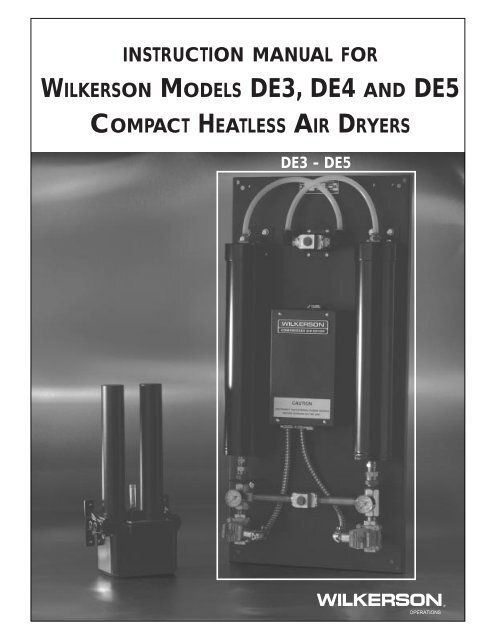
INSTRUCTION MANUAL FOR<br />
WILKERSON MODELS DE3, DE4 AND DE5<br />
COMPACT HEATLESS AIR DRYERS<br />
DE3 - DE5<br />
®<br />
OPERATIONS
<strong>Wilkerson</strong> Compact Heatless Air Dryers<br />
GENERAL<br />
This instruction manual covers the installation, operation, maintenance and troubleshooting guide<br />
for the <strong>Wilkerson</strong> compact heatless air dryers, models DE3, DE4 and DE5. These dryers are<br />
designed to be installed into a compressed air system, providing ultra-dry compressed air to<br />
moisture sensitive applications.<br />
C<br />
D<br />
J<br />
A<br />
B<br />
E<br />
F<br />
K<br />
MUFFLERS<br />
(OPTIONAL)<br />
G<br />
H<br />
L<br />
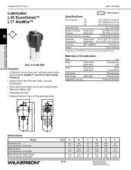
Outline Dimensions<br />
Figure 1<br />
Model<br />
Number<br />
A<br />
B<br />
C<br />
D<br />
E<br />
F<br />
G<br />
H<br />
J<br />
K<br />
L<br />
DE3<br />
DE4<br />
35.50<br />
35.50<br />
34.50<br />
34.50<br />
16.00<br />
16.00<br />
8.00<br />
8.00<br />
6.50<br />
6.50<br />
1.50<br />
1.50<br />
17.00<br />
17.00<br />
8.50<br />
8.50<br />
3.63<br />
3.63<br />
4.13<br />
4.13<br />
5.63<br />
5.63<br />
DE5<br />
41.00<br />
39.50<br />
18.62<br />
9.31<br />
6.50<br />
1.50<br />
20.13<br />
10.06<br />
6.75<br />
4.75<br />
6.38<br />
Instruction Manual / DE3, DE4 and DE5
<strong>Wilkerson</strong> Compact Heatless Air Dryers<br />
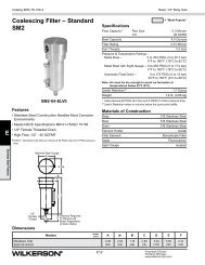
DESCRIPTION OF OPERATION<br />
<strong>Wilkerson</strong> DE series compact heatless air dryers employ the principles of pressure swing<br />
adsorption (PSA). The operation is fully automatic and relatively little maintenance is required.<br />
The dryers utilize two identical desiccant towers, a metering orifice, two shuttle valves, and two<br />
2-way AC operated solenoid valves controlled by a solid state electronic timer. Wet air at line<br />
pressure enters and flows through one of the towers where nearly all the water vapor is adsorbed<br />
while the other tower is being regenerated. A repressurization period follows the regeneration<br />
period. Every 60 seconds, the process is reversed, providing a continuous flow of dry air.<br />
In the flow schematic shown below, Valve A (closed, de-energized) and Valve B (open, energized)<br />
allow the inlet shuttle valve to direct the inlet air to flow into Tower A (drying). A portion of the dry<br />
outlet air is allowed to flow through the outlet shuttle valve purge orifice into Tower B. This dry<br />
purge air expands to nearly atmospheric pressure, sweeping the water out of the desiccant as it<br />
flows through Tower B (regenerating) and out of the Valve B (energized) exhaust port. The timer<br />
controls the cycling of normally closed solenoid valves.<br />
The orifices are fixed and are sized by the factory based on flow, pressure and dew point required.<br />
DESICCANT<br />
TOWER<br />
DESICCANT<br />
A<br />
TOWER DRY AIR<br />
TO APPLICATION<br />
TO APPLICATION<br />
DESICCANT<br />
DESICCANT TOWER B<br />
TOWER B<br />
OUTLET SHUTTLE<br />
VALVE WITH<br />
PURGE ORIFICE<br />
EXHAUST<br />
SOLENOID<br />
VALVE A<br />
INLET<br />
INLET<br />
SHUTTLE<br />
VALVE<br />
WET AIR IN IN<br />
EXHAUST<br />
SOLENOID<br />
VALVE B<br />
PURGE<br />
AIR<br />
EXHAUST<br />
EXHAUST<br />
DE3, DE4 and DE5<br />
Flow Schematic<br />
Figure 2<br />
Instruction Manual / DE3, DE4 and DE5
<strong>Wilkerson</strong> Compact Heatless Air Dryers<br />
INSTALLATION AND OPERATION<br />
NOTE:<br />
<strong>Wilkerson</strong> DE series compact heatless dryers have been<br />
thoroughly inspected and tested at the factory and are in<br />
proper working condition.<br />
A. Initial Inspection – Remove the air dryer from the shipping carton. Inspect the exterior and<br />
remove the electrical cover and inspect the interior components for any shipping damage.<br />
NOTE:<br />
Any damage noticed at this time must be brought to the<br />
immediate attention of the carrier and a freight claim must<br />
be filed.<br />
B. Warranty – Please read this instruction manual carefully before installing the air dryer.<br />
Failure to follow proper instructions could result in damage to the equipment and may void<br />
the product warranty.<br />
! CAUTION:<br />
!<br />
EXCEPT as otherwise specified by the manufacturer, this product<br />
is specifically designed for compressed air service and use with<br />
any other gas or liquid is a misapplication. Use with or injection<br />
of certain hazardous liquids or gases in the system (i.e., alcohol<br />
or liquid petroleum gas) could be harmful to the unit and result in<br />
a combustible condition or cause hazardous external leakage.<br />
Manufacturers' warranties are void in the event of a misapplication<br />
and manufacturer assumes NO RESPONSIBILITY for any<br />
resulting loss. Before using equipment with fluids or gases other<br />
than air, or for non-industrial applications, consult <strong>Wilkerson</strong><br />
<strong>Corporation</strong> for written approval.<br />
C. Installation/Mounting – Four mounting holes are provided for wall mounting of Models DE3,<br />
DE4 and DE5. All dryers require a clean ambient environment for proper operation. Normally,<br />
most locations where ambient temperatures range between 40˚F and 125˚F are suitable for<br />
installation since drying efficiency is more dependent on the temperature of the compressed air<br />
flowing through the unit. Operating a unit at temperatures which could result in freezing may<br />
cause damage to the dryer. Do not operate at temperatures so low that freezing is a possibility.<br />
1. Install dryer where ambient temperatures are between 40°F (4.4°C) and 125°F (52°C).<br />
2. Mount dryer in a vertical position.<br />
3. Piping connections: For maximum flow, INLET and OUTLET piping should be schedule 40<br />
pipe or equivalent I.D. tubing. DE3, DE4 and DE5 inlet and outlet ports are 1/2" female,<br />
NPT, purge porting is 1/2" female, NPT.<br />
Instruction Manual / DE3, DE4 and DE5
<strong>Wilkerson</strong> Compact Heatless Air Dryers<br />
NOTE<br />
If purge air is required to be piped to a remote location, it is<br />
necessary to use oversized tubing to prevent back-pressure.<br />
Restricting the purge flow can cause the dryer to malfunction.<br />
4. Use Teflon tape or pipe sealant on threads. Check all air connections for leakage, using<br />
soap solution prior to putting dryer into permanent service.<br />
5. It is recommended that a bypass line with shut-off valves be installed to provide constant<br />
air flow to the system, should the dryer require servicing.<br />
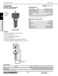
6. Always install a 5-micron particulate prefilter and a coalescing filter upstream to remove<br />
entrained particulates, moisture and oil. A 0.5-micron afterfilter should be installed downstream<br />
to remove any desiccant dust that may migrate from the desiccant towers.<br />
BYPASS SHUT-OFF VALVE<br />
BYPASS LINE<br />
MOISTURE<br />
INDICATOR<br />
5-MICRON<br />
PREFILTER<br />
WITH AUTO<br />
DRAIN<br />
MICROALESCER<br />
OPTIONAL<br />
REGULATOR<br />
SHUT-OFF<br />
VALVE<br />
AIR DRYER<br />
WITH MOISTURE<br />
INDICATOR<br />
SHUT-OFF<br />
VALVE<br />
0.5-MICRON<br />
POSTFILTER<br />
OPTIONAL<br />
REGULATOR<br />
Factory Recommended Dryer Installation<br />
Figure 3<br />
D. Operating Specifications – The DE3, DE4 and DE5 series compact heatless dryers can<br />
be sized to operate from 40 to 150 PSIG (2,7 to 10,3 bar).<br />
1. The dryers must be operated in accordance with the factory sizing charts and original customer<br />
requirements in order to achieve desired dewpoints. Inlet pressure, inlet temperature,<br />
and outlet flow conditions are always specified when purchased.<br />
2. Maximum inlet air temperature is 125°F (52°C).<br />
3. Do not operate dryers in temperatures so low that freezing is a possibility.<br />
E. Electrical Connections – Before wiring, check the dryer nameplate for electrical characteristics.<br />
Standard electrical characteristics are 115 Volt, 50/60Hz operation. Models operating on<br />
230 Volt, 50/60Hz operation are available.<br />
1. ! IMPORTANT! No overload protection is provided in the dryer and unit should be<br />
wired into a protected circuit. A knockout hole with romex connector is provided for<br />
electrical connection.<br />
Instruction Manual / DE3, DE4 and DE5
<strong>Wilkerson</strong> Compact Heatless Air Dryers<br />
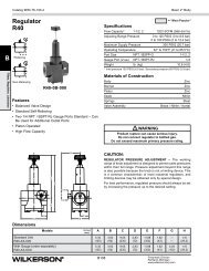
F. Solid State Timers – The solid state timer used in the DE3, DE4 and DE5 dryers control the<br />
switching of the solenoid valves during a two minute total time cycle. The timers are equipped<br />
with a one hour memory capability. If power is interrupted, the dryer will resume operation at<br />
the same point in the cycle when power is restored.<br />
Wiring Diagram<br />
Figure 4<br />
Instruction Manual / DE3, DE4 and DE5
<strong>Wilkerson</strong> Compact Heatless Air Dryers<br />
MAINTENANCE INSTRUCTIONS<br />
A. Field Adjustments – Following proper installation of the <strong>Wilkerson</strong> DE heatless air dryer, no<br />
field adjustments are necessary. No lubrication is required on the dryer.<br />
B. Six-Month Check – It is recommended that every 6 months of operation, unit be thoroughly<br />
inspected. Inspection should include audible inspection of the towers switching and purge flow.<br />
Visual inspection should include checking for excessive dirt or oil fouling and for desiccant<br />
attrition at the outlet and purge exhaust area. Remove mufflers, if installed, and check for<br />
excessive pressure drop by blowing through the muffler. If large resistance is felt, mufflers<br />
should be replaced.<br />
C. Purge Orifice – If the operating conditions change from the label specifications (eg. inlet pressure,<br />
outlet flow), it is necessary to replace the purge orifice. There is one orifice in the DE3,<br />
DE4 and DE5 air dryers. The orifice is an extremely critical part in determining the performance<br />
of the dryer and no attempt should be made to enlarge or reduce the hole size. An orifice<br />
of the proper size must be obtained from your local <strong>Wilkerson</strong> distributor. The label on the<br />
dryer should also be changed, noting the present operating conditions. The purge orifice is<br />
precision drilled in the outlet shuttle spool. To change the orifice, remove the three screws on<br />
one side of the outlet shuttle valve. Remove and replace the orifice. Reassemble shuttle valve.<br />
D. Cycle Timer – The solid state cycle timer requires no maintenance and can be replaced in<br />
field.<br />
E. Desiccant Towers – Desiccant towers are an all-welded design and are not repackable.<br />
Replacement chambers should be obtained from your local <strong>Wilkerson</strong> distributor.<br />
F. Operating Air Dryer Improperly – Following improper dryer operation, i.e., low inlet pressure,<br />
high air temperature or high outlet flow, shut off the outlet flow from the air dryer for several<br />
hours to allow the dryer to operate, purging the desiccant towers of excessive moisture. If this<br />
does not restore dryer to proper working order, consult the troubleshooting guide.<br />
G. Oil Contamination – Oil contamination of the desiccant towers will cause complete loss of<br />
drying capability. If oil is detected in the desiccant towers or any other components, it will be<br />
necessary to install replacement towers in order to restore dryer to normal operation. For this<br />
reason, proper maintenance of the prefilters is essential.<br />
H. Replacement Parts – Contact your local authorized <strong>Wilkerson</strong> distributor for dryers or replacement<br />
parts.<br />
IMPORTANT INFORMATION<br />
The installation of parts not supplied by<br />
<strong>Wilkerson</strong> will void the warranty of our air dryers.<br />
For replacement part information, contact <strong>Wilkerson</strong> Applications Engineering, toll free at<br />
1-888-223-5126.<br />
Instruction Manual / DE3, DE4 and DE5
<strong>Wilkerson</strong> Compact Heatless Air Dryers<br />
DE3, DE4 and DE5 Parts Identification<br />
7 8<br />
,<br />
11<br />
10<br />
6<br />
1<br />
12<br />
13<br />
2<br />
5<br />
3 4<br />
,<br />
9<br />
Parts Identification<br />
Figure 5<br />
Instruction Manual / DE3, DE4 and DE5
<strong>Wilkerson</strong> Compact Heatless Air Dryers<br />
PARTS DESCRIPTION – DE3, DE4 AND DE5 HEATLESS DRYERS<br />
ITEM NO. PART QTY. PER PART DESCRIPTION INCLUDES<br />
NUMBER DRYER ITEMS<br />
1 DRP-94-301 2 Desiccant Tower, New, DE3<br />
DRP-94-302 2 Desiccant Tower, New, DE4<br />
DRP-94-303 2 Desiccant Tower, New, DE5<br />
2 DRP-94-399 2 Purge Solenoid Valve, 115V.<br />
DRP-94-400 2 Purge Solenoid Valve, 230V.<br />
DRP-94-321-2 2 Solenoid Coil Only, 115V.<br />
DRP-94-322-2 2 Solenoid Coil Only, 230V.<br />
DRP-94-311 2 Valve Maintenance Kit<br />
3 DRP-94-393 1 Inlet Shuttle Valve 4<br />
4 DRP-94-600 1 Inlet Shuttle Spool Only<br />
5 DRP-94-374 1 Power On/Off Switch<br />
6 DRP-94-335 1 Solid State Timer, 115V.<br />
DRP-94-336 1 Solid State Timer, 230V.<br />
7 DRP-94-394 1 Outlet Shuttle Valve (Specify Orifice No.) 8<br />
8* DRP-94-6XX 1 Purge Orifice (Specify Orifice No.)<br />
For Dryers<br />
PARTS FOR OPTIONS<br />
with Option<br />
Codes<br />
9 DRP-94-371 2 Purge Muffler, 1/2", DE3/DE4 M<br />
DRP-94-372 2 Purge Muffler, 3/4", DE5 M<br />
10 DRP-94-375 1 Humidistat Board W/ Sensor Cord E, H<br />
not shown DRP-94-376 1 Moisture Sensor E, H<br />
11 DRP-94-377 1 Relay, Shut-off Valve E, H<br />
12 DRP-94-378 1 Sonalert E, H<br />
not shown DRP-94-379 1 Lamp, Humidity Alarm E, H<br />
13 DRP-94-380 2 Tower Pressure Gauge E, H, P<br />
not shown DRP-94-399 1 Shut-off Solenoid Valve, 115V. E<br />
not shown DRP-94-400 1 Shut-off Solenoid Valve, 230V. E<br />
When ordering parts, always state the dryer Model Number and Serial Number.<br />
*Orifice number must be specified. This can be obtained from nameplate data.<br />
Instruction Manual / DE3, DE4 and DE5
<strong>Wilkerson</strong> Compact Heatless Air Dryers<br />
A<br />
MODELS DE3, DE4 AND DE5 TROUBLESHOOTING GUIDE<br />
PROBLEM: AIR DRYER DELIVERS WET AIR<br />
POSSIBLE CAUSE CHECK CORRECTIVE ACTION<br />
A1 No power to unit. On/off switch or power supply. Correct power problem.<br />
A2 High inlet air temperature. Inlet air temperature should not Reduce inlet air temperature.<br />
exceed sizing criteria stated<br />
at purchase (usually<br />
70˚F or 100˚F).<br />
A3 Air demand in excess of rated Check downstream flow demand Reduce air usage downstream.<br />
capacity of air dryer.<br />
with flowmeter.<br />
A4 Low inlet pressure. Verify actual inlet pressure vs. Increase inlet pressure or call<br />
nameplate operating pressure. factory to resize dryer for<br />
inlet conditions.<br />
A5 Dirty or obstructed inlet air filter. Check filter element. Replace.<br />
A6 Purge orifice plugged. Remove and inspect purge orifice. Clean hole of debris. Use air<br />
gun to clean.<br />
A7 Solenoid coil burned out. Check magnetic field from coil Replace.<br />
operation. Place iron or steel<br />
material (screwdriver or nail) top<br />
of coil to feel the magnetic effect,<br />
indicating proper operation.<br />
(Note: each coil should be<br />
energized for 40 seconds every<br />
other minute).<br />
A8 Oil contamination of Verify particle/coalescing inlet Towers must be replaced if<br />
desiccant beds. filtration is adequate and contamination is suspected.<br />
functioning properly.<br />
A9 Timer not operating properly. Verify correct timing cycle. At no time should there be<br />
1. With terminals pulled back simultaneous signals at S1<br />
slightly from lugs on timer, place and S2.<br />
voltmeter across N and S1.<br />
There should be a 115 volt AC Replace timer if defective.<br />
signal for 40 seconds and<br />
0 volts for 80 seconds.<br />
2. Check across N and S2 for<br />
same timing.<br />
A10 Purge flow restricted. Check mufflers for excessive back Replace mufflers.<br />
pressure.<br />
If purge air is piped away from<br />
unit, oversized piping should be<br />
used and length of run should be<br />
as short as possible.<br />
Instruction Manual / DE3, DE4 and DE5
<strong>Wilkerson</strong> Compact Heatless Air Dryers<br />
B<br />
MODELS DE3, DE4 AND DE5 TROUBLESHOOTING GUIDE<br />
PROBLEM: RESTRICTED FLOW THROUGH UNIT<br />
POSSIBLE CAUSE CHECK CORRECTIVE ACTION<br />
B1 Improper operating conditions. See A2, A3, A4 above.<br />
B2 Dirty or obstructed inlet air See A5 above.<br />
filter.<br />
B3 Plugged air passages. Check inlet and outlet air Clear restrictions.<br />
passages and piping for<br />
blockages.<br />
Instruction Manual / DE3, DE4 and DE5
<strong>Wilkerson</strong> Compact Heatless Air Dryers<br />
C<br />
MODELS DE3, DE4 AND DE5 TROUBLESHOOTING GUIDE<br />
PROBLEM: EXCESSIVE PURGE / BLOWDOWN<br />
POSSIBLE CAUSE CHECK CORRECTIVE ACTION<br />
C1 Inlet or outlet shuttle not Verify nameplate specifications vs. Line pressure too low at inlet:<br />
shifting. actual operating parameters. Increase line pressure or call<br />
factory to resize purge orifice<br />
for new conditions.<br />
C2 Inlet or outlet shuttle not Verify nameplate specifications vs. Turn off downstream air usage.<br />
shifting. actual operating parameters. If blowdown events stop<br />
occurring, this indicates the air<br />
flow was too much for the<br />
compressor capacity or airline<br />
diameter causing excessive<br />
pressure drop.<br />
C3 Inlet or outlet shuttle not Check for damage or contamina- Clean or replace as necessary.<br />
shifting.<br />
tion of inlet and outlet shuttles.<br />
C4 Inlet or outlet shuttle not Dirty or obstructed inlet air filter. Check filter element. Replace.<br />
shifting.<br />
C5 Purge orifice plugged. Remove and inspect purge orifice. Clean hole of debris. Use air gun<br />
to clean.<br />
C6 Timer not operating properly. Swith connections to S1 and S2 Replace timer.<br />
on the solid state timer. If<br />
symptoms appear on opposite<br />
purge port, the timer is defective.<br />
C7 Timer not operating properly. Incoming power is not “clean.” Supply line voltage from<br />
Fluctuations in voltage can occur another source.<br />
in power circuits shared by<br />
inductive devices such as<br />
electric motors.<br />
C8 Timer not operating properly. Verify correct timing cycle. At no time should there be<br />
1. With terminals pulled back simultaneous signals at S1<br />
slightly from lugs on timer, place and S2.<br />
voltmeter across N and S1.<br />
There should be a 115 volt AC<br />
signal for 40 seconds and<br />
0 volts for 80 seconds.<br />
2. Check across N and S2 for<br />
same timing.<br />
C9 Leakage. With dryer pressurized, remove Repair as necessary.<br />
power form dryer. Check purge<br />
ports for large leaks. Check all<br />
joints on dryer and air system<br />
for large leaks.<br />
Instruction Manual / DE3, DE4 and DE5
<strong>Wilkerson</strong> Compact Heatless Air Dryers<br />
D<br />
D1<br />
MODELS DE3, DE4 AND DE5 TROUBLESHOOTING GUIDE<br />
PROBLEM: ALARM WILL NOT CLEAR<br />
POSSIBLE CAUSE CHECK CORRECTIVE ACTION<br />
Wet air condition not corrected. See Section "A" of<br />
Troubleshooting Guide.<br />
D2 Sensor not dried out. Allow several minutes for To speed up alarm clearing,<br />
sensor to dry out after correcting bleed some air through tire valve<br />
dryer problem. Alarm should clear. at bottom of sensor housing.<br />
Alarm should clear in less than<br />
than 60 seconds.<br />
D3 Bad humidistat board. Disconnect humidity cable from Replace humidistat board.<br />
sensor. Alarm should clear.<br />
Instruction Manual / DE3, DE4 and DE5
<strong>Wilkerson</strong> Compact Heatless Air Dryers<br />
E<br />
MODELS DE3, DE4 AND DE5 TROUBLESHOOTING GUIDE<br />
PROBLEM: NO ALARM DURING WET AIR CONDITION<br />
POSSIBLE CAUSE CHECK CORRECTIVE ACTION<br />
E1 No power to humidistat With voltmeter, check for line Make sure there is power to<br />
board. voltage at "Hot" and "Neutral" dryer. Check wiring diagram<br />
terminals on humidistat board. for correct wiring. Check<br />
Also check for line voltage at continuity of wires.<br />
"Common" and "Neutral".<br />
E2 Sensor cable connection. Check cable connections at Reconnect<br />
sensor and at humidistat board.<br />
E3 Bad sensor. Remove air pressure from dryer. Replace sensor.<br />
With sensor cable connected and<br />
power on, unscrew brass hex nut<br />
at bottom of sensor housing. Blow<br />
gently on sensor. The moist air<br />
from your breath should cause<br />
the alarm to sound.<br />
E4 Bad humidistat board. Press red "Push to Test" button on Replace humidistat board.<br />
humidistat board. Alarm should<br />
sound.<br />
Instruction Manual / DE3, DE4 and DE5
<strong>Wilkerson</strong> Compact Heatless Air Dryers<br />
F<br />
MODELS DE3, DE4 AND DE5 TROUBLESHOOTING GUIDE<br />
PROBLEM: SHUTTLE VAL VE NOT FUNCTIONING PROPERLY<br />
POSSIBLE CAUSE CHECK CORRECTIVE ACTION<br />
F1 No power to shutoff With power on, disconnect If voltage at #17 and #18, and<br />
solenoid valve. humidity alarm sensor cable voltage at #11 and #15, and no<br />
from sensor. This will make<br />
voltage at #15 and #16, relay is<br />
sure unit is not in alarm and<br />
bad. Replace relay.<br />
shutoff valve should be<br />
energized. With voltmeter,<br />
check for line voltage at<br />
shutoff solenoid valve, wires<br />
#15 and #16. If not reading line<br />
voltage, check wires #17 and<br />
#18, then wires #11 and #18.<br />
F2 Coil burned out. With power on, disconnect If no magnetic effect can be felt,<br />
humidity sensor cable from<br />
replace coil.<br />
sensor. This will make sure unit<br />
is not in alarm and shutoff valve<br />
should be energized. Check<br />
magnetic field from coil operation.<br />
Hold iron or steel material<br />
(screwdriver end or nail) at top of<br />
coil to feel the magnetic effect,<br />
indicating proper operation.<br />
F3 Valve needs maintenance If valve leaks with power off or if Install valve maintenance kit.<br />
kit.<br />
causes F1 and F2 are eliminated,<br />
you may need to install a valve<br />
maintenance kit.<br />
Instruction Manual / DE3, DE4 and DE5
<strong>Wilkerson</strong> Compact Heatless Air Dryers<br />
Instruction Manual / DE3, DE4 and DE5 <strong>83</strong>-<strong>919</strong>-<strong>000</strong>-FL 6/98