KM Bolt-On Weight Sensors - Kistler-Morse
KM Bolt-On Weight Sensors - Kistler-Morse
KM Bolt-On Weight Sensors - Kistler-Morse

You also want an ePaper? Increase the reach of your titles
YUMPU automatically turns print PDFs into web optimized ePapers that Google loves.
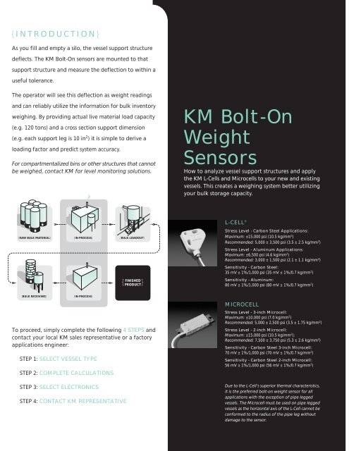
{INTRODUCTION}<br />
As you fill and empty a silo, the vessel support structure<br />
deflects. The <strong>KM</strong> <strong>Bolt</strong>-<strong>On</strong> sensors are mounted to that<br />
support structure and measure the deflection to within a<br />
useful tolerance.<br />
The operator will see this deflection as weight readings<br />
and can reliably utilize the information for bulk inventory<br />
weighing. By providing actual live material load capacity<br />
(e.g. 120 tons) and a cross section support dimension<br />
(e.g. each support leg is 10 in 2 ) it is simple to derive a<br />
loading factor and predict system accuracy.<br />
For compartmentalized bins or other structures that cannot<br />
be weighed, contact <strong>KM</strong> for level monitoring solutions.<br />
<strong>KM</strong> <strong>Bolt</strong>-<strong>On</strong><br />
<strong>Weight</strong><br />
<strong>Sensors</strong><br />
How to analyze vessel support structures and apply<br />
the <strong>KM</strong> L-Cells and Microcells to your new and existing<br />
vessels. This creates a weighing system better utilizing<br />
your bulk storage capacity.<br />
L-CELL ®<br />
{RAW BULK MATERIAL}<br />
{IN-PROCESS}<br />
{BULK LOADOUT}<br />
Stress Level - Carbon Steel Applications:<br />
Maximum: ±15,000 psi (10.5 kg/mm 2 )<br />
Recommended: 5,000 ± 3,500 psi (3.5 ± 2.5 kg/mm 2 )<br />
Stress Level - Aluminum Applications:<br />
Maximum: ±6,500 psi (4.6 kg/mm 2 )<br />
Recommended: 3,000 ± 1,500 psi (2.1 ± 1.1 kg/mm 2 )<br />
Sensitivity - Carbon Steel:<br />
35 mV ± 1%/1,000 psi (35 mV ± 1%/0.7 kg/mm 2 )<br />
FINISHED<br />
{ PRODUCT}<br />
Sensitivity - Aluminum:<br />
80 mV ± 1%/1,000 psi (80 mV ± 1%/0.7 kg/mm 2 )<br />
{BULK RECEIVING}<br />
{IN-PROCESS}<br />
To proceed, simply complete the following 4 STEPS and<br />
contact your local <strong>KM</strong> sales representative or a factory<br />
applications engineer:<br />
STEP 1: SELECT VESSEL TYPE<br />
STEP 2: COMPLETE CALCULATIONS<br />
STEP 3: SELECT ELECTRONICS<br />
STEP 4: CONTACT <strong>KM</strong> REPRESENTATIVE<br />
MICROCELL<br />
Stress Level - 3-inch Microcell:<br />
Maximum: ±10,000 psi (7.0 kg/mm 2 )<br />
Recommended: 5,000 ± 2,500 psi (3.5 ± 1.75 kg/mm 2 )<br />
Stress Level - 2-inch Microcell:<br />
Maximum: ±15,000 psi (10.5 kg/mm 2 );<br />
Recommended: 7,500 ± 3,750 psi (5.3 ± 2.6 kg/mm 2 )<br />
Sensitivity - Carbon Steel 3-inch Microcell:<br />
70 mV ± 1%/1,000 psi (70 mV ± 1%/0.7 kg/mm 2 )<br />
Sensitivity - Carbon Steel 2-inch Microcell:<br />
56 mV ± 1%/1,000 psi (56 mV ± 1%/0.7 kg/mm 2 )<br />
Due to the L-Cell’s superior thermal characteristics,<br />
it is the preferred bolt-on weight sensor for all<br />
applications with the exception of pipe legged<br />
vessels. The Microcell must be used on pipe legged<br />
vessels as the horizontal axis of the L-Cell cannot be<br />
conformed to the radius of the pipe leg without<br />
damage to the sensor.
Bulk<br />
Inventory<br />
<strong>Weight</strong><br />
Measurement<br />
Using:<br />
Product<br />
Selection<br />
and<br />
Application<br />
Guide<br />
{VESSEL TYPES}<br />
{VERTICAL LEG VESSELS}<br />
{HORIZONTAL BEAM VESSELS}<br />
STEP 1 STEP 1<br />
STEP 1<br />
{KISTLER-MORSE}<br />
{SKIRTED SILOS}
{LEG SUPPORTED VESSELS}<br />
Is this a stand-alone vessel supported on legs?<br />
If YES, find the best match for your vessel type from drawings 101 to 401. Proceed to STEP 2.<br />
If NO, go to section entitled HORIZONTAL BEAM SUPPORTED VESSELS.<br />
101<br />
N=0<br />
102<br />
N=0<br />
202<br />
N=1<br />
NOTE: Other L-Cell mounting locations for series 200 and up<br />
may be feasible for increased accuracy. Consult factory.<br />
502 502 502<br />
201<br />
N=1<br />
{HORIZONTAL BEAM SUPPORTED VESSELS}<br />
Is this vessel supported by horizontal beams and/or diagonals?<br />
If YES, find the best match for your vessel type from drawings 502 to 602. Proceed to STEP 2<br />
If NO, go to section entitled SKIRTED SILOS.<br />
551<br />
553<br />
203<br />
N=2<br />
553 553<br />
301<br />
N=2<br />
302<br />
N=2<br />
303<br />
N=2<br />
601 601 601<br />
304<br />
N=2<br />
401<br />
N=2<br />
LEGEND<br />
Mounting Location for L-Cell<br />
N Cross-Brace Effect<br />
STEP 2 STEP 2<br />
602 602<br />
651 651 651 701<br />
LEGEND<br />
Vertical Leg<br />
Vessel Support Point<br />
Ring Supported Vessel<br />
Mounting Location for L-Cell<br />
{SKIRTED SILOS}<br />
Does only the skirt support this vessel?<br />
If YES, find the best match for your Vessels Diameter. Proceed to STEP 2<br />
If NO, consult with the factory.<br />
4 5 3<br />
6<br />
4 5 6<br />
3 7<br />
2<br />
1<br />
8<br />
5 6 7<br />
4 8<br />
3 9<br />
2 10<br />
1<br />
45 6 7 8<br />
9<br />
10<br />
3 11<br />
2 12<br />
1<br />
5<br />
6 7 8 9<br />
10<br />
11<br />
4<br />
3<br />
2<br />
1<br />
12<br />
13<br />
14<br />
7 8 9 10<br />
11<br />
6<br />
12<br />
5<br />
4<br />
3<br />
2<br />
1<br />
13<br />
14<br />
15<br />
16<br />
8 9 10 11<br />
7<br />
12<br />
6<br />
5<br />
13<br />
14<br />
4<br />
3<br />
2<br />
1<br />
15<br />
16<br />
17<br />
8<br />
7<br />
6<br />
5<br />
4<br />
9 10 11 12 13<br />
14<br />
15<br />
16<br />
17<br />
3<br />
2<br />
1<br />
18<br />
19<br />
20<br />
STEP 2<br />
9’ (2.7m) Dia.<br />
9’- 5” (2.9m)<br />
L-Cell Spacing<br />
12’ (3.7m) Dia.<br />
9’- 5” (2.9m)<br />
L-Cell Spacing<br />
15’ (4.6m) Dia.<br />
9’- 5” (2.9m)<br />
L-Cell Spacing<br />
2 1<br />
LEGEND<br />
18’ (5.5m) Dia.<br />
9’- 5” (2.9m)<br />
L-Cell Spacing<br />
21’ (6.4m) Dia.<br />
9’- 5” (2.9m)<br />
L-Cell Spacing<br />
24’ (7.3m) Dia.<br />
9’- 5” (2.9m)<br />
L-Cell Spacing<br />
26’ (7.9m) Dia.<br />
9’- 5” (2.9m)<br />
L-Cell Spacing<br />
28’ (8.5m) Dia.<br />
8’-10” (2.7m)<br />
L-Cell Spacing<br />
L-Cell Set<br />
Junction Box<br />
Door
Number of Similar Vessels<br />
Vessel Type (Select closest type 101-104)<br />
Leg Type<br />
(If pipe leg - use Microcells in same configuration as L-Cells)<br />
LEG TYPES<br />
A<br />
C<br />
B<br />
I-BEAM<br />
Area = (A x 2B) x C<br />
A<br />
C<br />
B<br />
ANGLE<br />
Area = (A + B) x C<br />
Live Load (Working capacity)<br />
lbs<br />
Number of Legs<br />
Live Load per Leg (See formula)<br />
Steel Area Calculation (See Leg Type formula)<br />
Load Factor (See formulas)<br />
Percentage ±Error (From chart at right) ±<br />
Accuracy (In pounds)<br />
±<br />
Proceed to STEP 3<br />
lbs<br />
in 2<br />
psi<br />
%<br />
lbs<br />
FORMULAS<br />
A T T D<br />
B<br />
TUBULAR<br />
Area = (2A + 2B) x T<br />
PIPE<br />
Area = 3.14 x D x T<br />
Live Load per Leg = Live Load (Working capacity) ÷ Number of Legs<br />
Load Factor (psi) = Live Load per Leg ÷ Steel Area Calculation<br />
Accuracy in Pounds = Live Load x ±Error% (From chart at right)<br />
Number of Similar Vessels<br />
Vessel Type (Select closest type 502-602)<br />
LEG TYPE<br />
A<br />
D<br />
Live Load (Working capacity)<br />
Number of Support Beams<br />
lbs<br />
I-BEAM<br />
Shear Area = A x D<br />
Live Load per Support Point Beam (See formula)<br />
Steel Area Calculation (See Shear Area formula)<br />
lbs<br />
in 2<br />
FORMULA<br />
Load factor (See formula)<br />
psi<br />
Percentage ±Error (From chart at right)<br />
±<br />
%<br />
Accuracy (In pounds)<br />
±<br />
lbs<br />
Proceed to STEP 3<br />
Number of Similar Silos<br />
Silo Type (<strong>Bolt</strong>ed or Welded)<br />
SILO<br />
TYPE<br />
Live Load (Working capacity)<br />
lbs<br />
Vessel (D)iameter (In inches)<br />
in<br />
Skirt (T)hickness (In inches)<br />
in<br />
T<br />
Load Factor (See formula)<br />
psi<br />
D<br />
Percentage ±Error (From chart at right)<br />
Accuracy (In pounds)<br />
±<br />
±<br />
%<br />
lbs<br />
FORMULA<br />
Load Factor (psi) = Live Load (Working capacity) ÷ (3.14 x D x T)<br />
Proceed to STEP 3<br />
Accuracy in Pounds = Live Load x ±Error% (From chart at right)
LEG ACCURACY CHART<br />
{± ERROR %}<br />
9<br />
8<br />
7<br />
6<br />
5<br />
4<br />
3<br />
2<br />
1<br />
CONSULT FACTORY<br />
{3089 psi}<br />
{example}<br />
Outside N=0<br />
Outside N=1<br />
Outside N=2<br />
Inside N=0<br />
Inside N=1<br />
Inside N=2<br />
EXAMPLE {see example to the left}<br />
Storage silo located outside with a capacity of 120,000 lbs. It is supported<br />
by four 10” I-Beam legs (that are type W10X33). There are no braces.<br />
Vessel Type 101<br />
Leg Type I-Beam W10X33 (10” x 8”)<br />
Live Load<br />
120,000 lbs<br />
Number of Legs 4<br />
Live Load per Leg 120,000 ÷ 4 = 30,000 lbs per Leg<br />
Steel Area Calc. 9.71 in 2<br />
Load Factor<br />
3,089 psi<br />
Accuracy<br />
±2.5% of 120,000 lbs = ±3,000 lbs<br />
2 L-Cells per leg with appropriate electronics.<br />
0<br />
0 1000 2000 3000 4000 5000 6000 7000 8000 9000<br />
{STRESS IN PSI}<br />
See Vessel Drawing for N value.<br />
HORIZONTAL ACCURACY CHART<br />
{± ERROR %}<br />
9<br />
8<br />
7<br />
6<br />
5<br />
4<br />
3<br />
2<br />
1<br />
0<br />
0<br />
CONSULT FACTORY<br />
{example}<br />
{3600 psi}<br />
1000 2000 3000 4000 5000 6000 7000 8000 9000<br />
{STRESS IN PSI}<br />
4 Cells/Beam<br />
2 Cells/Beam<br />
1 Cell/Beam<br />
EXAMPLE {see example to the left}<br />
Load out vessel located outside with a capacity of 120,000 lbs. It is beam<br />
supported by four diagonal 12” I-Beams (that are type W12X53). There<br />
are no other support points. NOTE: In load out applications, batch<br />
accuracy is typically greater than inventory accuracy as stated.<br />
Vessel Type 551<br />
Leg Type I-Beam W12X53 (12” x 10”)<br />
Live Load<br />
120,000 lbs<br />
Number of Beams 4<br />
Live Load per Beam 120,000 ÷ 4 = 30,000 lbs per support Beam<br />
Shear Load per Beam 30,000 ÷ 2 = 15,000<br />
Steel Area Calc. 4.161 in 2<br />
Load Factor<br />
3,605 psi<br />
Accuracy<br />
±1.75% of 120,000 lbs = ±2,100 lbs<br />
2 L-Cells per support beam with appropriate electronics.<br />
STEP 3<br />
SKIRT ACCURACY CHART<br />
{± ERROR %}<br />
18<br />
16<br />
14<br />
12<br />
10<br />
8<br />
6<br />
4<br />
2<br />
CONSULT FACTORY<br />
{2123 psi}<br />
{example}<br />
Best Case<br />
Worst Case<br />
Working Area<br />
EXAMPLE {see example to the left}<br />
Receiving silo for flour is a Peabody bolted TecTank ® that is 12’ in<br />
diameter by 56’ tall and located outside. It has a skirt thickness of 3/16”<br />
and holds 180,000 lbs. The fill method is pneumatic and the use of the<br />
system will be for inventory purposes.<br />
Vessel Type<br />
Skirted Silo (<strong>Bolt</strong>ed)<br />
Live Load<br />
180,000 lbs<br />
Vessel Diameter 144 in (12 Feet)<br />
Skirt Thickness 3/16 in (0.1875)<br />
Load Factor<br />
2,123 psi<br />
Accuracy<br />
±3.0 to 5.0% of 180,000 lbs = ±5,400 to 9,000 lbs<br />
4 sets of L-Cells per silo with appropriate electronics.<br />
0<br />
0 1000 2000 3000 4000 5000 6000 7000 8000 9000<br />
{SKIRT STRESS IN PSI}
STEP 3 STEP 4<br />
Select the electronics<br />
and options that meet<br />
your requirements.<br />
SVS2000<br />
A single-vessel weight indicator featuring easy to read<br />
LCD display, menu driven “quick-config” and net/tare/gross<br />
functions with modular output options. NEMA 4X plastic.<br />
WEIGH ll<br />
A 1-4 vessel weight indicator featuring easy to read LCD<br />
display, menu driven “quick-config” and net/tare/gross<br />
functions with modular output options. NEMA 4X plastic.<br />
MVS 4D (MULTI-VESSEL SYSTEM)<br />
A controller for measuring and monitoring bulk material<br />
inventories. By combining simple plug-in input and<br />
output cards to match your specific needs this multivessel<br />
system will monitor and provide control for up<br />
to 32 vessels.<br />
MVS 8D (MULTI-VESSEL SYSTEM)<br />
A vessel controller (19” rack configuration) for<br />
measuring and monitoring bulk material inventories.<br />
By combining simple plug-in input and output cards<br />
to match your specific needs this multi-vessel, rack<br />
mount system will monitor and provide control for<br />
up to 120 vessels.<br />
{FAX TO<br />
FACTORY}<br />
425.402.1500<br />
VESSEL INFORMATION<br />
Type<br />
Capacity<br />
PSI<br />
Accuracy<br />
ELECTRONIC INFORMATION<br />
Type<br />
Options<br />
Date<br />
1<br />
1-4<br />
1-32<br />
Number of Vessels<br />
1-120<br />
SITE INFORMATION<br />
Company Name<br />
Address<br />
City, State, Zip<br />
Phone<br />
( )<br />
Monitored<br />
Opt<br />
Opt<br />
Opt<br />
Opt<br />
Analog (4-20 mA)<br />
CONTACT INFORMATION<br />
Name<br />
Title<br />
Std<br />
Opt<br />
Opt<br />
Opt<br />
Relay Setpoints<br />
Opt<br />
Std<br />
Std<br />
Std<br />
Serial Communications<br />
RS422/485<br />
Opt<br />
N/A<br />
N/A<br />
N/A<br />
Fax<br />
DeviceNet<br />
Allen-Bradley<br />
Remote I/O(RIO)<br />
Opt<br />
Opt<br />
Opt<br />
Opt<br />
( )<br />
Phone ( )<br />
Fax ( )<br />
Std<br />
Std<br />
Std<br />
Opt<br />
Nema 4X Enclosure<br />
Stainless Steel<br />
Enclosure<br />
Opt Std<br />
Opt Std<br />
Opt Std<br />
N/A Std<br />
CE Approval<br />
UL Approval<br />
Std<br />
N/A<br />
N/A<br />
N/A
NOTES:<br />
P/N 97-5092<br />
<strong>KM</strong> is represented in your area by:<br />
WORLD HEADQUARTERS<br />
19021 120th Ave. NE<br />
Bothell, WA 98011 USA<br />
1.800.426.9010<br />
tel: 425.486.6600<br />
fax: 425.402.1500<br />
kistlermorse.com<br />
EUROPE<br />
Rucaplein 531<br />
B-2610 Wilrijk-Belgium<br />
+32.3.218.99.99<br />
fax: +32.3.230.78.76<br />
kistler.morse@skynet.be