4.7 fuel tank (carbu - harley-davidson-sweden.se
4.7 fuel tank (carbu - harley-davidson-sweden.se
4.7 fuel tank (carbu - harley-davidson-sweden.se

You also want an ePaper? Increase the reach of your titles
YUMPU automatically turns print PDFs into web optimized ePapers that Google loves.
HOME<br />
SPECIFICATIONS 4.1<br />
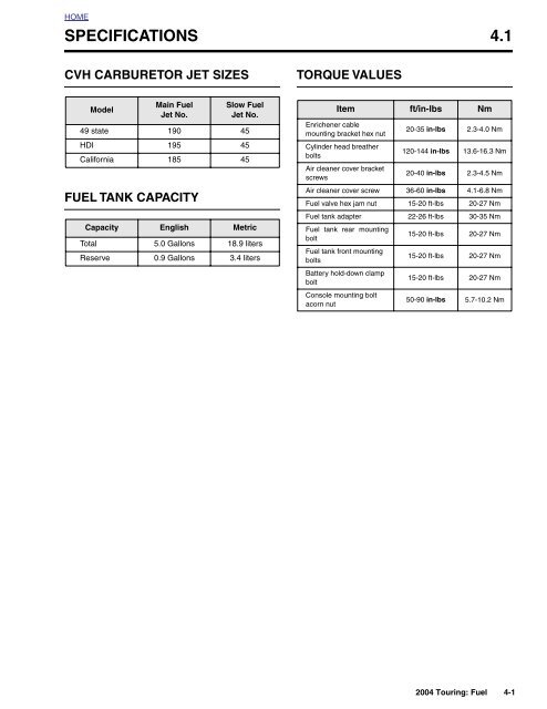
CVH CARBURETOR JET SIZES<br />
TORQUE VALUES<br />
Model<br />
Main Fuel<br />
Jet No.<br />
FUEL TANK CAPACITY<br />
Slow Fuel<br />
Jet No.<br />
49 state 190 45<br />
HDI 195 45<br />
California 185 45<br />
Capacity English Metric<br />
Total 5.0 Gallons 18.9 liters<br />
Re<strong>se</strong>rve 0.9 Gallons 3.4 liters<br />
Item ft/in-lbs Nm<br />
Enrichener cable<br />
mounting bracket hex nut<br />
20-35 in-lbs 2.3-4.0 Nm<br />
Cylinder head breather<br />
bolts<br />
120-144 in-lbs 13.6-16.3 Nm<br />
Air cleaner cover bracket<br />
screws<br />
20-40 in-lbs 2.3-4.5 Nm<br />
Air cleaner cover screw 36-60 in-lbs 4.1-6.8 Nm<br />
Fuel valve hex jam nut 15-20 ft-lbs 20-27 Nm<br />
Fuel <strong>tank</strong> adapter 22-26 ft-lbs 30-35 Nm<br />
Fuel <strong>tank</strong> rear mounting<br />
bolt<br />
15-20 ft-lbs 20-27 Nm<br />
Fuel <strong>tank</strong> front mounting<br />
bolts<br />
15-20 ft-lbs 20-27 Nm<br />
Battery hold-down clamp<br />
bolt<br />
15-20 ft-lbs 20-27 Nm<br />
Console mounting bolt<br />
acorn nut<br />
50-90 in-lbs 5.7-10.2 Nm<br />
2004 Touring: Fuel 4-1
HOME<br />
FUEL SYSTEM TROUBLESHOOTING (CARBURETED) 4.2<br />
\<br />
CARBURETOR TROUBLESHOOTING<br />
OVERFLOW<br />
Check for:<br />
1. Restricted <strong>fuel</strong> <strong>tank</strong> vent system.<br />
2. Loo<strong>se</strong> float bowl screws.<br />
3. Damaged float bowl O-ring.<br />
4. Improper <strong>fuel</strong> level in float bowl.<br />
5. Damaged or leaking float as<strong>se</strong>mbly.<br />
6. Particle contamination in <strong>fuel</strong> inlet fitting cavity.<br />
7. Worn or dirty inlet valve or <strong>se</strong>at.<br />
Remedy:<br />
1. Correct restricted ho<strong>se</strong>. Replace vapor valve.<br />
2. Tighten screws.<br />
3. Replace O-ring.<br />
4. Adjust float tab for correct <strong>fuel</strong> level.<br />
5. Replace float as<strong>se</strong>mbly.<br />
6. Clean and clear cavity and <strong>fuel</strong> supply tract.<br />
7. Clean or replace valve and clean <strong>se</strong>at.<br />
POOR IDLING<br />
Check for:<br />
1. Idle speed improperly adjusted.<br />
2. Inlet system air leak (faster idling).<br />
3. Loo<strong>se</strong> low speed jet.<br />
4. Contaminated or plugged low speed system.<br />
5. Enrichener valve not <strong>se</strong>ated or leaking.<br />
6. Leaking accelerator pump.<br />
Remedy:<br />
1. Adjust operating idle speed.<br />
2. Correct as required.<br />
3. Tighten jet.<br />
4. Clean contaminants and clear passages.<br />
5. Adjust, clean or replace.<br />
6. Repair.<br />
POOR FUEL ECONOMY<br />
Check for:<br />
1. High speed riding style.<br />
2. Excessive u<strong>se</strong> of enrichener system.<br />
3. Fuel level too high.<br />
4. Restricted <strong>fuel</strong> <strong>tank</strong> vent system.<br />
5. Dirty air cleaner element.<br />
6. Excessive accelerator pump output.<br />
7. Plugged or restricted bowl vent.<br />
8. Vacuum piston as<strong>se</strong>mbly malfunction.<br />
9. Loo<strong>se</strong> jets.<br />
10. Worn or damaged needle or needle jet.<br />
11. Plugged air jets or passages.<br />
12. Enrichener valve not <strong>se</strong>ated or leaking.<br />
13. Idle speed improperly adjusted.<br />
Remedy:<br />
1. Modify riding habits.<br />
2. Limit system u<strong>se</strong>.<br />
3. Adjust float level.<br />
4. Correct restricted ho<strong>se</strong>. Replace vapor valve.<br />
5. Clean or replace as required.<br />
6. Check and clean accelerator pump bypass orifice.<br />
7. Clean and clear passages.<br />
8. See Vacuum Piston Troubleshooting.<br />
9. Tighten jets.<br />
10. Replace needle or needle jet.<br />
11. Clean and clear passages.<br />
12. Adjust, clean or replace.<br />
13. Adjust operating idle speed.<br />
POOR ACCELERATION<br />
Check for:<br />
1. Throttle cables misadjusted.<br />
2. Inlet system air leak.<br />
3. Restricted <strong>fuel</strong> <strong>tank</strong> vent system.<br />
4. Restricted <strong>fuel</strong> supply passages.<br />
5. Plugged bowl vent or overflow.<br />
6. Enrichener valve not <strong>se</strong>ated or leaking.<br />
7. Worn or damaged needle or needle jet.<br />
8. Vacuum piston malfunction.<br />
9. Plugged jets or passages.<br />
10. Fuel level (float chamber) too low.<br />
11. Accelerator pump leaking or no output.<br />
Remedy:<br />
1. Adjust throttle cables.<br />
2. Correct as required.<br />
3. Correct restricted ho<strong>se</strong>. Replace vapor valve.<br />
4. Correct and clear restriction.<br />
5. Clean and clear passages.<br />
6. Adjust, clean or replace.<br />
7. Replace as<strong>se</strong>mbly.<br />
8. See Vacuum Piston Troubleshooting.<br />
9. Clean and clear as required.<br />
10. Adjust float level.<br />
11. Repair as necessary.<br />
4-2 2004 Touring: Fuel
HOME<br />
HARD STARTING<br />
Check for:<br />
1. Enrichener system plugged, not properly functioning<br />
or improperly operated.<br />
2. Inlet system air leak.<br />
3. Restricted <strong>fuel</strong> supply.<br />
4. Fuel overflow.<br />
5. Plugged slow jet or passages.<br />
Remedy:<br />
1. Clean, adjust, or replace; or read Owner’s Manual.<br />
2. Correct as required.<br />
3. Check <strong>fuel</strong> supply and/or passages. Verify that vacuum<br />
operated <strong>fuel</strong> valve is functional.<br />
4. See Overflow Troubleshooting.<br />
5. Clean and clear jet or passages.<br />
POOR PERFORMANCE ON ROAD<br />
Check for:<br />
1. Inlet system air leak.<br />
2. Restricted <strong>fuel</strong> <strong>tank</strong> vent system.<br />
3. Dirty or damaged air cleaner element.<br />
4. Accelerator pump inoperative.<br />
5. Plugged bowl vent or overflow.<br />
6. Vacuum piston as<strong>se</strong>mbly malfunction.<br />
7. Loo<strong>se</strong> or plugged <strong>fuel</strong> and air jets or passages.<br />
8. Worn or damaged needle or needle jet.<br />
9. Restricted <strong>fuel</strong> supply tract.<br />
10. Enrichener valve not <strong>se</strong>ated or leaking.<br />
11. Idle speed improperly adjusted.<br />
Remedy:<br />
1. Correct as required.<br />
2. Correct restricted ho<strong>se</strong>. Replace vapor valve.<br />
3. Clean or replace.<br />
4. Repair as required.<br />
5. Clean and clear passages.<br />
6. See Vacuum Piston Troubleshooting.<br />
7. Clean, clear and correct as required.<br />
8. Replace as<strong>se</strong>mbly.<br />
9. Correct and clear restriction.<br />
10. Adjust, clean or replace.<br />
11. Adjust operating idle speed.<br />
POOR HIGH SPEED PERFORMANCE<br />
Check for:<br />
1. Inlet system air leak.<br />
2. Restricted <strong>fuel</strong> <strong>tank</strong> vent system.<br />
3. Dirty or damaged air cleaner element.<br />
4. Accelerator pump inoperative.<br />
5. Plugged bowl, vent or overflow.<br />
6. Vacuum piston as<strong>se</strong>mbly malfunction.<br />
7. Restricted <strong>fuel</strong> supply tract.<br />
8. Loo<strong>se</strong> or plugged main jets or passages.<br />
9. Improper <strong>fuel</strong> level.<br />
10. Worn or damaged needle or needle jet.<br />
11. Enrichener valve not <strong>se</strong>ated or leaking.<br />
Remedy:<br />
1. Clean or replace.<br />
2. Correct restricted ho<strong>se</strong>. Replace vapor valve.<br />
3. Clean or replace.<br />
4. Repair as required.<br />
5. Clean and clear passages.<br />
6. See Vacuum Piston Troubleshooting.<br />
7. Correct and clean restriction.<br />
8. Tighten, clean, clear as required.<br />
9. Adjust float level.<br />
10. Replace as<strong>se</strong>mbly.<br />
11. Adjust, clean or replace.<br />
2004 Touring: Fuel 4-3
HOME<br />
VACUUM PISTON ASSEMBLY TROUBLESHOOTING<br />
PISTON DOES NOT RAISE PROPERLY<br />
Check for:<br />
1. Diaphragm cap loo<strong>se</strong>, damaged or leaking.<br />
2. Diaphragm pinched at lip groove.<br />
3. Piston atmosphere vent blocked.<br />
4. Piston vacuum passage plugged.<br />
5. Torn diaphragm.<br />
6. Piston binding.<br />
7. Spring binding.<br />
8. Enrichener valve open, not <strong>se</strong>ated or leaking.<br />
Remedy:<br />
1. Tighten or replace cap.<br />
2. Reposition diaphragm lip.<br />
3. Clear vent.<br />
4. Clean and clear passage.<br />
5. Replace piston diaphragm as<strong>se</strong>mbly.<br />
6. Clean piston slides and body or replace piston.<br />
7. Correct or replace spring.<br />
8. Adjust, clean or replace.<br />
PISTON DOES NOT CLOSE PROPERLY<br />
Check for:<br />
1. Piston diaphragm ring dirty or damaged.<br />
2. Piston binding.<br />
3. Spring damaged.<br />
Remedy:<br />
1. Clean or replace piston.<br />
2. Clean piston slides and body or replace piston.<br />
3. Replace spring.<br />
4-4 2004 Touring: Fuel
HOME<br />
ENRICHENER (CARBURETED) 4.3<br />
GENERAL<br />
The <strong>carbu</strong>retor is a constant velocity, gravity fed type with a<br />
float operated inlet valve, a variable venturi, a throttle stop<br />
screw for idle speed adjustment and a <strong>fuel</strong> enrichment system<br />
for starting. See Figure 4-1.<br />
The <strong>fuel</strong> enrichment circuit will cau<strong>se</strong> engine idle speed to<br />
increa<strong>se</strong> to approximately 2000 rpm with enrichener knob<br />
pulled out fully and engine running at normal operating temperature.<br />
With enrichener knob pulled out partially and<br />
engine running at normal operating temperature, engine idle<br />
speed will also increa<strong>se</strong> above normal idle speed. The<br />
increa<strong>se</strong> in idle speed is intended to alert the rider that<br />
engine is warmed up, and that enrichener knob should be<br />
pushed in all the way. Continued u<strong>se</strong> of enrichener after<br />
engine is warmed up may cau<strong>se</strong> fouled spark plugs.<br />
Idle and transfer ports provide a balanced <strong>fuel</strong> mixture during<br />
the transition period from stop to mid-range. A vacuum piston<br />
controls venturi opening.<br />
The <strong>carbu</strong>retor is specifically designed to control exhaust<br />
emissions. All jets are fixed. The idle mixture has been pre<strong>se</strong>t<br />
at the factory.<br />
f1381b2x<br />
Vacuum Piston<br />
Chamber<br />
Idle Control<br />
Cable<br />
Throttle Control<br />
Cable<br />
Vacuum Fitting<br />
(At Back)<br />
The idle mixture screw is reces<strong>se</strong>d in the <strong>carbu</strong>retor casting.<br />
The opening is <strong>se</strong>aled with a plug becau<strong>se</strong> it is intended that<br />
the idle mixture be non-adjustable.<br />
Idle Speed<br />
Set Screw<br />
NOTE<br />
Adjusting mixture <strong>se</strong>tting by procedures other than specified<br />
in this <strong>se</strong>ction may be in violation of Federal or State regulations.<br />
Air<br />
Jets<br />
Accelerator<br />
Pump Nozzle<br />
Float Chamber<br />
This system partially compensates for changes in the mixture<br />
that are normally cau<strong>se</strong>d by changes in altitude. Becau<strong>se</strong><br />
atmospheric pressure decrea<strong>se</strong>s as altitude increa<strong>se</strong>s, the<br />
pressure difference in the upper and lower chambers is<br />
reduced, which provides less <strong>fuel</strong> to the engine.<br />
The <strong>carbu</strong>retor is equipped with an accelerator pump. The<br />
accelerator pump system u<strong>se</strong>s sudden throttle openings<br />
(rapid accelerations) to quickly inject <strong>fuel</strong> into <strong>carbu</strong>retor venturi<br />
to provide extra <strong>fuel</strong> for smooth acceleration.<br />
OPERATION<br />
Enrichener<br />
The enrichener knob, located under the left side of the <strong>fuel</strong><br />
<strong>tank</strong>, controls opening and closing of the enrichener circuit in<br />
the <strong>carbu</strong>retor. The enrichener knob can be adjusted to any<br />
position, from full-in to full-out.<br />
CAUTION<br />
Never accelerate the engine above 2500 RPM immediately<br />
after a cold start. Allow the engine to run slowly for<br />
15-30 <strong>se</strong>conds. This will allow the engine to warm up and<br />
let oil reach all surfaces needing lubrication. Extended<br />
idling with enrichener in the full out position for a period<br />
longer than 30 <strong>se</strong>conds is not recommended.<br />
●<br />
Figure 4-1. CVH Carburetor<br />
NOTE<br />
H-D CV <strong>carbu</strong>retors have an enrichener circuit that will<br />
cau<strong>se</strong> the engine to idle at approximately 2000 rpm with<br />
the engine at normal operating temperature and the<br />
enrichener knob pulled fully out.<br />
2004 Touring: Fuel 4-5
HOME<br />
●<br />
●<br />
The increa<strong>se</strong> in idle speed is intended to alert the rider<br />
that the engine is warmed up to normal operating temperature<br />
and the enrichener knob should be pushed all<br />
the way in.<br />
Continuing to u<strong>se</strong> the enrichener when the engine is at<br />
full operating temperature WILL CAUSE FOULED<br />
SPARK PLUGS.<br />
Full-Out<br />
(Cold Engine Starts)<br />
1/2-Way<br />
Position<br />
Full-In<br />
(Normal Running Position)<br />
CAUTION<br />
Pay clo<strong>se</strong> attention to the vehicle's warm-up time. Either<br />
excessive or insufficient u<strong>se</strong> of the enrichener may<br />
cau<strong>se</strong> poor performance, erratic idle, poor <strong>fuel</strong> economy<br />
and spark plug fouling.<br />
NOTE<br />
The following starting and operating instructions for all <strong>carbu</strong>reted<br />
motorcycles should be viewed as recommendations<br />
only. They may be modified for individual vehicles.<br />
Cool Engine<br />
Outside Temperature Cooler than 60˚ F<br />
Turn the <strong>fuel</strong> valve to the ON position. BE SURE THAT THE<br />
THROTTLE IS CLOSED. Pull the enrichener knob to the “full<br />
out” position. Turn the Ignition/Light Key Switch knob to the<br />
IGNITION position. Turn the Engine Stop Switch to the RUN<br />
position. Press the Engine Start Switch to operate the electric<br />
starter.<br />
1. After initial 15-30 <strong>se</strong>cond warm-up, ride for 3 minutes or<br />
2 miles (3.2 km) with enrichener knob in full out position.<br />
See Figure 4-2.<br />
2. Push the enrichener knob in to the 1/2 way position. Ride<br />
an additional 2 minutes or 2 miles (3.2 km).<br />
3. Push the enrichener knob fully in.<br />
NOTE<br />
If outside temperature is cooler than 20˚ F it may be necessary<br />
to pump the throttle control grip 2 or 3 times.<br />
Outside Temperature Warmer than 60˚ F<br />
Turn the <strong>fuel</strong> valve to the ON position. BE SURE THAT THE<br />
THROTTLE IS CLOSED. Pull the enrichener knob to the “full<br />
out” position. Turn the Ignition/Light Key Switch knob to the<br />
IGNITION position. Turn the Engine Stop Switch to the RUN<br />
position. Press the Engine Start Switch to operate the electric<br />
starter.<br />
1. After the initial 15-30 <strong>se</strong>cond warm-up, ride for 1 minute<br />
or 1/2 mile (0.8 km) with enrichener knob in full out position.<br />
See Figure 4-2.<br />
2. Push the enrichener knob in to the 1/2 way position. Ride<br />
an additional 1 minute or 1/2 mile (0.8 km).<br />
3. Push the enrichener knob fully in.<br />
Warm Climate Or Hot Engine<br />
Turn the <strong>fuel</strong> valve to the ON position. Turn the Ignition/Light<br />
Key Switch knob to the IGNITION position. Turn the Engine<br />
Stop Switch to the RUN position. Open throttle 1/8 - 1/4 turn.<br />
Press the Engine Start Switch to operate the electric starter.<br />
DO NOT USE ENRICHENER.<br />
NOTE<br />
If the engine does not start after a few turns or if one cylinder<br />
fires weakly but engine does not start, it is usually becau<strong>se</strong> of<br />
an over-rich (flooded) condition. This is especially true of a<br />
hot engine. If the engine is flooded, push enrichener knob in<br />
all the way, turn ignition on and operate starter with throttle<br />
wide open. DO NOT "pump" the throttle while turning over the<br />
engine.<br />
ADJUSTMENTS<br />
Slow Idle<br />
Figure 4-2. Set the Enrichener Knob<br />
f1808x4x<br />
NOTE<br />
Make certain the enrichener knob is pushed all the way in<br />
before adjusting engine idle. The CV <strong>carbu</strong>retor enrichenercircuit<br />
will cau<strong>se</strong> the engine idle speed to increa<strong>se</strong> to<br />
between 1500 and 2000 rpm with the enrichener knob pulled<br />
out fully and the engine at normal operating temperature.<br />
(With the enrichener knob pulled out partially and normal<br />
engine operating temperature, the engine idle speed will<br />
increa<strong>se</strong> above normal idle speed (950-1050 rpm) to approximately<br />
2000 rpm maximum with the enrichener knob pulled<br />
out fully). The increa<strong>se</strong> in idle speed is intended to alert the<br />
rider that the engine is warmed-up and the enrichener knob<br />
should be pushed all the way in. Continued u<strong>se</strong> of the<br />
enrichener, after engine is at normal operating temperature,<br />
may cau<strong>se</strong> fouled spark plugs.<br />
With the engine at normal operating temperature and the<br />
enrichener all the way in (enrichener valve clo<strong>se</strong>d) adjust the<br />
throttle stop screw so the engine idles at 1000 rpm.<br />
4-6 2004 Touring: Fuel
HOME<br />
NOTE<br />
U<strong>se</strong> a test tachometer, connected to negative ignition coil terminal<br />
to measure engine rpm on models without tachometers.<br />
Enrichener Control<br />
At the 1000 mile (1600 km) <strong>se</strong>rvice interval, and at every<br />
5000 mile (8000 km) <strong>se</strong>rvice interval thereafter, inspect the<br />
enrichener control as follows:<br />
The <strong>fuel</strong> enrichener knob should open, remain open and then<br />
clo<strong>se</strong> without binding. The knurled plastic nut next to the<br />
enrichener knob controls the ea<strong>se</strong> at which the cable slides<br />
within the conduit.<br />
If adjustment is needed:<br />
1. See Figure 4-3. Loo<strong>se</strong>n hex nut at backside of mounting<br />
bracket.<br />
2. Move cable as<strong>se</strong>mbly free of slot in mounting bracket.<br />
3. Hold cable as<strong>se</strong>mbly at flat with adjustable wrench.<br />
Hand turn knurled nut counterclockwi<strong>se</strong> to reduce sliding<br />
resistance until knob slides inward unaided.<br />
4. Turn knurled nut clockwi<strong>se</strong> to increa<strong>se</strong> sliding resistance<br />
until knob remains fully out without holding and then<br />
clo<strong>se</strong>s with relative ea<strong>se</strong>.<br />
Enrichener<br />
Knob<br />
Knurled<br />
Nut<br />
Mounting<br />
Bracket<br />
Flat<br />
Figure 4-3. Enrichener Control<br />
5. Slide enrichener cable into slot of mounting bracket. Flat<br />
on threads must face rear of motorcycle for script on<br />
enrichener knob to be right side up. With external tooth<br />
lockwasher and hex nut positioned on the inboard side<br />
of the mounting bracket, tighten hex nut to 20-35 in-lbs<br />
(2.3-4.0 Nm).<br />
CAUTION<br />
Lockwasher<br />
Hex<br />
Nut<br />
Enrichener<br />
Cable<br />
f1438x4x<br />
Do not lubricate the cable or inside of conduit. The cable<br />
must have sliding resistance to work properly.<br />
2004 Touring: Fuel 4-7
HOME<br />
1. Top<br />
2. Screw and washer (3)<br />
3. Spring<br />
4. Vacuum piston<br />
5. Spring <strong>se</strong>at<br />
6. Jet needle<br />
7. Vacuum ho<strong>se</strong><br />
8. Needle jet<br />
9. Needle jet holder<br />
10. Main jet<br />
11. Slow jet<br />
12. 4-sided Fuel valve with clip<br />
13. Pin<br />
18<br />
3<br />
5<br />
6<br />
2<br />
31<br />
1<br />
28<br />
14. Float<br />
15. O-ring<br />
16. O-ring<br />
17. Screw and washer (4)<br />
18. Cable guide<br />
19. Starter cap<br />
20. Cable <strong>se</strong>aling cap<br />
21. Enrichener valve<br />
22. Spring<br />
23. Bracket, throttle cable<br />
24. Screw (throttle cable bracket)<br />
25. Screw (throttle cable bracket)<br />
26. Screw (idle speed adjust)<br />
27. Spring<br />
28. Collar<br />
29. Seal ring<br />
30. Manifold<br />
31. Flange<br />
32. Seal, intake manifold (2)<br />
33. Lever<br />
34. Float bowl<br />
35. E-clip<br />
36. Accelerator pump nozzle<br />
4<br />
30<br />
47<br />
19<br />
20<br />
31<br />
22<br />
21<br />
7<br />
29<br />
32<br />
24<br />
26<br />
8<br />
9<br />
10<br />
17<br />
16<br />
36<br />
12<br />
NOTE<br />
With the exception of the jet sizes, all<br />
FL models are equipped with the<br />
same basic <strong>carbu</strong>retor.<br />
46<br />
49<br />
52<br />
11 33<br />
53<br />
v<br />
i d<br />
y<br />
a r l e<br />
D a<br />
H<br />
13<br />
14<br />
40<br />
34<br />
39<br />
38<br />
41<br />
42<br />
43<br />
35<br />
45<br />
49<br />
44<br />
27<br />
51<br />
15<br />
25<br />
23<br />
37<br />
54<br />
50<br />
48<br />
37. Spring<br />
38. Pump housing<br />
39. Spring<br />
40. Diaphragm<br />
41. O-Ring (2)<br />
42. Washer<br />
43. Screw (3)<br />
44. Boot<br />
45. Rod<br />
46. Collar<br />
47. Screw (4)<br />
48. Rod<br />
49. Cotter pin (2)<br />
50. Washer<br />
51. Washer<br />
52. Washer<br />
53. Washer<br />
54. Collar<br />
f2277x4x<br />
Figure 4-4. Carburetor<br />
4-8 2004 Touring: Fuel
HOME<br />
CARBURETOR 4.4<br />
REMOVAL<br />
1WARNING<br />
Gasoline is extremely flammable and highly explosive.<br />
When <strong>se</strong>rvicing the <strong>fuel</strong> system, do not smoke or allow<br />
open flame or sparks in the vicinity. Inadequate safety<br />
precautions could result in death or <strong>se</strong>rious injury.<br />
Float Bowl<br />
Vent<br />
1. Remove maxi-fu<strong>se</strong>. See Section 8.3 SYSTEM FUSES,<br />
MAXI-FUSE, REMOVAL.<br />
2. Remove air cleaner as<strong>se</strong>mbly. See Section 4.5 AIR<br />
CLEANER, REMOVAL.<br />
3. Locate the <strong>fuel</strong> enrichener knob under the left side of the<br />
<strong>fuel</strong> <strong>tank</strong>, and loo<strong>se</strong>n hex nut at backside of mounting<br />
bracket. Slide cable as<strong>se</strong>mbly free of slot in mounting<br />
bracket.<br />
4. Rotate handle on <strong>fuel</strong> valve to the horizontal position to<br />
shut the gasoline supply to the <strong>carbu</strong>retor OFF.<br />
Figure 4-5. Drain Carburetor Float Bowl<br />
8982<br />
1WARNING<br />
Some gasoline will drain from the <strong>fuel</strong> inlet ho<strong>se</strong> when<br />
disconnected from the <strong>carbu</strong>retor. Thoroughly wipe up<br />
any spilled <strong>fuel</strong> immediately. Dispo<strong>se</strong> of rags in a suitable<br />
manner. Gasoline is extremely flammable and<br />
highly explosive. Inadequate safety precautions could<br />
result in death or <strong>se</strong>rious injury.<br />
5. Using a side cutters, cut clamp and remove <strong>fuel</strong> inlet<br />
ho<strong>se</strong> from fitting at side of <strong>carbu</strong>retor.<br />
NOTE<br />
On California models, pull purge tube from fitting on same<br />
side of <strong>carbu</strong>retor.<br />
6. Gently work <strong>carbu</strong>retor free of <strong>se</strong>al ring on intake manifold.<br />
1WARNING<br />
As the <strong>carbu</strong>retor is removed, be sure to keep as<strong>se</strong>mbly<br />
upright as the float bowl contains gasoline. Tilting the<br />
<strong>carbu</strong>retor or turning it upside down will cau<strong>se</strong> the gasoline<br />
to drain onto surrounding area. Gasoline is<br />
extremely flammable and highly explosive. Inadequate<br />
safety precautions could result in death or <strong>se</strong>rious<br />
injury.<br />
7. If crui<strong>se</strong> control equipped, remove E-clip from groove at<br />
end of crui<strong>se</strong> cable housing. Remove crui<strong>se</strong> cable housing<br />
from cable guide in throttle cable bracket. Push plastic<br />
end fitting on crui<strong>se</strong> cable to outboard side to relea<strong>se</strong><br />
from wheel pin.<br />
8. Using a needle no<strong>se</strong> pliers, carefully pull idle cable barrel<br />
from upper inboard hole in throttle wheel. Pull throttle<br />
cable barrel from remaining hole. Relea<strong>se</strong> idle and throttle<br />
cables from guides in throttle cable bracket.<br />
9. Pull vacuum ho<strong>se</strong> elbow from fitting on inboard side of<br />
<strong>carbu</strong>retor.<br />
10. Carefully remove <strong>carbu</strong>retor while drawing enrichener<br />
cable to right side of motorcycle.<br />
11. Keeping <strong>carbu</strong>retor upright, move as<strong>se</strong>mbly to bench<br />
area. Tilting <strong>carbu</strong>retor, carefully pour gasoline in float<br />
bowl into a suitable container. Gasoline will exit float<br />
bowl vent shown in Figure 4-5.<br />
INSTALLATION<br />
1. Place <strong>carbu</strong>retor into approximate position on right side<br />
of motorcycle while feeding enrichener cable over to left<br />
side.<br />
2. Push vacuum ho<strong>se</strong> elbow onto fitting on inboard side of<br />
<strong>carbu</strong>retor.<br />
3. Install sleeve on throttle cable housing into shorter cable<br />
guide in throttle cable bracket. Drawing throttle cable<br />
downward, fit barrel end into lower outboard hole in<br />
throttle wheel. Install sleeve and spring on idle cable<br />
housing into longer cable guide in<strong>se</strong>rting barrel end into<br />
upper inboard hole in throttle wheel.<br />
2004 Touring: Fuel 4-9
HOME<br />
8981<br />
10. Install air cleaner as<strong>se</strong>mbly. See Section 4.5 AIR<br />
CLEANER, INSTALLATION.<br />
11. Install maxi-fu<strong>se</strong>. See Section 8.3 SYSTEM FUSES,<br />
MAXI-FUSE, INSTALLATION.<br />
12. Rotate handle of <strong>fuel</strong> valve clockwi<strong>se</strong> to the vertical position<br />
and carefully inspect for leaks. Return the valve to<br />
the OFF position when finished.<br />
13. Adust the engine idle speed. See Section 4.3<br />
ENRICHENER (CARBURETED), ADJUSTMENTS.<br />
DISASSEMBLY<br />
Vacuum Piston Chamber<br />
Figure 4-6. Remove Enrichener Cable<br />
4. Verify that cables are fully <strong>se</strong>ated in channel of throttle<br />
wheel, and using cable adjusters at handlebar, tighten<br />
cables as necessary to keep barrel ends from dislodging.<br />
Verify operation by turning throttle grip and ob<strong>se</strong>rving<br />
cable action.<br />
5. If crui<strong>se</strong> control equipped, slide plastic end fitting over<br />
cap of wheel pin. Push on end fitting until it snaps in<br />
place. Slip crui<strong>se</strong> cable housing into cable guide in throttle<br />
cable bracket. Install new E-clip into groove at end of<br />
crui<strong>se</strong> cable housing.<br />
NOTE<br />
The fit between the <strong>carbu</strong>retor and <strong>se</strong>al ring is tight. Prior to<br />
as<strong>se</strong>mbly, lubricate mating surfaces with liquid dishwashing<br />
soap or tire mounting lube. Always install new <strong>se</strong>al ring if<br />
dried out, cracked or otherwi<strong>se</strong> damaged.<br />
6. Lubricate inside diameter of <strong>se</strong>al ring. Also apply a light<br />
film of lubricant to <strong>carbu</strong>retor housing where casting<br />
comes into contact with <strong>se</strong>al ring. Gently work <strong>carbu</strong>retor<br />
into <strong>se</strong>al ring.<br />
7. Slide new clamp onto free end of <strong>fuel</strong> inlet ho<strong>se</strong>. Install<br />
ho<strong>se</strong> onto brass fitting at side of <strong>carbu</strong>retor. Making sure<br />
clamp is positioned inboard of lip on fitting, crimp clamp<br />
using HOSE CLAMP PLIERS (HD-97087-65B).<br />
NOTE<br />
On California models, push purge tube onto fitting on same<br />
side of <strong>carbu</strong>retor.<br />
8. Moving to left side of motorcycle, slide threaded portion<br />
of enrichener cable into slot of mounting bracket. Flat on<br />
threads must face rear of motorcycle for script on<br />
enrichener knob to be right side up. With the external<br />
tooth lockwasher and hex nut positioned on the inboard<br />
side of the mounting bracket, tighten hex nut to 20-35 inlbs<br />
(2.3-4.0 Nm).<br />
9. Adjust throttle cables. See Section 2.21 THROTTLE<br />
CABLES (NON-CRUISE), ADJUSTMENT.<br />
1. Placing a 14mm open end wrench on hex, loo<strong>se</strong>n plastic<br />
fitting at enrichener bore of <strong>carbu</strong>retor housing. See Figure<br />
4-6. Rotate enrichener cable in a counterclockwi<strong>se</strong><br />
direction to unthread fitting and remove valve as<strong>se</strong>mbly.<br />
2. Remove gold Phillips screw (with lockwasher) at side of<br />
<strong>carbu</strong>retor to relea<strong>se</strong> throttle cable bracket. Remove gold<br />
Phillips screw (with top collar) to free throttle cable<br />
bracket from <strong>carbu</strong>retor top. Set bracket aside.<br />
3. Remove three remaining top screws to relea<strong>se</strong> <strong>carbu</strong>retor<br />
top from body.<br />
4. Remove vacuum piston spring. Carefully rai<strong>se</strong> diaphragm<br />
to remove vacuum piston as<strong>se</strong>mbly. Remove<br />
spring <strong>se</strong>at and jet needle from vacuum piston bore. See<br />
Figure 4-7.<br />
Float Chamber<br />
1. Turn <strong>carbu</strong>retor upside down and remove four Phillips<br />
screws at bottom to remove float bowl from <strong>carbu</strong>retor<br />
body.<br />
Vacuum<br />
Piston<br />
Jet<br />
Needle<br />
7754<br />
Spring<br />
Spring<br />
Seat<br />
Figure 4-7. Vacuum Piston Chamber Components<br />
4-10 2004 Touring: Fuel
HOME<br />
NOTE<br />
Since accelerator pump rod is now loo<strong>se</strong>, remove from hole<br />
in lever at side of <strong>carbu</strong>retor body.<br />
A<br />
Float<br />
7751<br />
CAUTION<br />
Tapping the float pin out from the squared pedestal side<br />
will result in damage that requires <strong>carbu</strong>retor replacement<br />
2. Using a small center punch and hammer, carefully tap<br />
float pin from holes in pedestals. The rounded pedestal<br />
has an interference fit to ensure that the float pin is<br />
<strong>se</strong>curely held, so always tap out the pin in the direction<br />
of the cast-in arrow (that is, from the interference side).<br />
See Figure 4-8.<br />
3. Remove float and <strong>fuel</strong> valve. Carefully slide clip on <strong>fuel</strong><br />
valve from tab on float. Remove wireform clip from<br />
groove in <strong>fuel</strong> valve. See A of Figure 4-9.<br />
4. Using slot at top, turn main jet with flat tip screwdriver to<br />
unthread from needle jet holder. If necessary, hold hex<br />
on needle jet holder with a 5/16 inch wrench to prevent<br />
rotation. See Figure 4-11.<br />
5. Using a 5/16 inch wrench, turn hex on needle jet holder<br />
to unthread from main jet bore.<br />
6. Turn <strong>carbu</strong>retor right side up to drop out needle jet,<br />
which is loo<strong>se</strong> in main jet bore. See B of Figure 4-9.<br />
7. In<strong>se</strong>rt thin bladed flat tip screwdriver into slow jet bore.<br />
See Figure 4-11. Using slot at top of slow jet, unthread<br />
to remove. See C of Figure 4-9.<br />
8. Disas<strong>se</strong>mble accelerator pump from float bowl. See Figure<br />
4-10. Proceed as follows:<br />
Float Pin<br />
B<br />
C<br />
Needle Jet Holder<br />
Needle Jet<br />
Slow Jet<br />
Fuel Valve<br />
Main Jet<br />
Wireform<br />
Clip<br />
Figure 4-9. Float Chamber Components<br />
7750<br />
7755<br />
Rounded<br />
Pedestal<br />
Rod<br />
Rubber<br />
Boot<br />
f1868x4x<br />
Spring<br />
Float Pin<br />
O-Rings<br />
Diaphragm<br />
Figure 4-10. Accelerator Pump Components<br />
Arrow<br />
a0183x4x<br />
Figure 4-8. Remove Float Pin in Direction of Arrow<br />
a. Remove rubber boot from post at top of accelerator<br />
pump upper housing.<br />
b. Turn float bowl upside down. Alternately loo<strong>se</strong>n and<br />
then remove three Phillips screws (with lockwashers)<br />
to relea<strong>se</strong> accelerator pump lower housing.<br />
2004 Touring: Fuel 4-11
HOME<br />
c. Remove spring and diaphragm from accelerator<br />
pump upper housing. Remove two O-rings from<br />
lower housing.<br />
CLEANING AND INSPECTION<br />
Carburetor Housing<br />
1. Clean all internal air/<strong>fuel</strong> passages in <strong>carbu</strong>retor housing<br />
with <strong>carbu</strong>retor cleaner. Blow out passages using low<br />
pressure compres<strong>se</strong>d air. Proceed as follows:<br />
1WARNING<br />
Compres<strong>se</strong>d air can pierce the skin and cau<strong>se</strong> injury.<br />
Never u<strong>se</strong> your hand to check for leaks or to determine<br />
air flow rates. Wear safety glas<strong>se</strong>s to shield your eyes<br />
from flying dirt and debris. Failure to comply could result<br />
in death or <strong>se</strong>rious injury.<br />
Slow Speed Circuit<br />
a. Spray <strong>carbu</strong>retor cleaner into air inlet hole of slow<br />
speed circuit. See A of Figure 4-12. While spraying,<br />
verify that solution exits slow jet bore at bottom of<br />
<strong>carbu</strong>retor housing. See B of Figure 4-12. Placing<br />
gloved finger over slow jet bore, verify that solution<br />
exits four pin holes just inboard of the throttle plate,<br />
as well as the single pin hole outboard of the throttle<br />
plate.<br />
b. Using a tapered, rubber-tipped nozzle on the air<br />
ho<strong>se</strong> (to prevent both loss of air pressure and to<br />
avoid scratching or nicking the bore), apply low pressure<br />
compres<strong>se</strong>d air into air inlet hole to blow <strong>carbu</strong>retor<br />
cleaner out of slow jet bore. Placing gloved<br />
finger over slow jet bore, blow <strong>carbu</strong>retor cleaner out<br />
of pin holes inboard and outboard of throttle plate.<br />
8979<br />
Main Jet<br />
Figure 4-11. Carburetor Housing<br />
Slow Jet<br />
Fuel Valve<br />
Bore<br />
Main Circuit<br />
a. Plugging main jet hole in <strong>carbu</strong>retor throat, spray<br />
<strong>carbu</strong>retor cleaner into air inlet hole of main circuit.<br />
See A of Figure 4-12. While spraying, verify that<br />
solution exits main jet bore at bottom of <strong>carbu</strong>retor<br />
housing. See B of Figure 4-12.<br />
b. Using a tapered, rubber-tipped nozzle on the air<br />
ho<strong>se</strong> (to prevent both loss of air pressure and to<br />
avoid scratching or nicking the bore), apply low pressure<br />
compres<strong>se</strong>d air into air inlet hole to blow <strong>carbu</strong>retor<br />
cleaner out of hole in <strong>carbu</strong>retor throat. Placing<br />
gloved finger over hole in <strong>carbu</strong>retor throat, blow<br />
<strong>carbu</strong>retor cleaner out of main jet bore at bottom of<br />
<strong>carbu</strong>retor housing.<br />
Float Bowl Vent<br />
a. Spray <strong>carbu</strong>retor cleaner into air inlet hole of float<br />
bowl vent. See A of Figure 4-12. While spraying, verify<br />
that solution exits two holes in float bowl chamber<br />
at bottom of <strong>carbu</strong>retor housing. See B of Figure 4-<br />
12.<br />
b. Using a tapered, rubber-tipped nozzle on the air<br />
ho<strong>se</strong> (to prevent both loss of air pressure and to<br />
avoid scratching or nicking the bore), apply low pressure<br />
compres<strong>se</strong>d air into air inlet hole of float bowl<br />
vent to blow <strong>carbu</strong>retor cleaner out of holes in float<br />
bowl chamber.<br />
Vacuum Piston Chamber Components<br />
1. Thorougly clean all loo<strong>se</strong> parts (except diaphragm) with<br />
<strong>carbu</strong>retor cleaner. See Figure 4-7. Blow dry using low<br />
pressure compres<strong>se</strong>d air.<br />
1WARNING<br />
Compres<strong>se</strong>d air can pierce the skin and cau<strong>se</strong> injury.<br />
Never u<strong>se</strong> your hand to check for leaks or to determine<br />
air flow rates. Wear safety glas<strong>se</strong>s to shield your eyes<br />
from flying dirt and debris. Failure to comply could result<br />
in death or <strong>se</strong>rious injury.<br />
2. Inspect parts as follows:<br />
a. Hold vacuum piston up to strong light source. Examine<br />
diaphragm for pin holes, cuts, tears or pinching.<br />
Replace if any damage is found.<br />
b. Examine passage at bottom of vacuum piston bore.<br />
Verify that passage is clean and open.<br />
c. Examine vacuum piston spring for stretching, kinking,<br />
distortion or other damage. Inspect spring <strong>se</strong>at<br />
for cracks. Replace parts if necessary.<br />
d. Examine slides at sides of vacuum piston to verify<br />
that surfaces are clean and smooth. Clean or buff<br />
out any rough surfaces.<br />
e. Examine tip of jet needle for grooves or scratches.<br />
Needle should be completely straight, while surface<br />
condition at taper should be smooth and even.<br />
Replace needle if necessary.<br />
4-12 2004 Touring: Fuel
HOME<br />
A<br />
Slow Speed<br />
Circuit<br />
Air Inlet<br />
B<br />
Main Jet<br />
Bore<br />
Float Chamber Components<br />
1. Thorougly clean all loo<strong>se</strong> parts with <strong>carbu</strong>retor cleaner.<br />
See Figure 4-9. Blow dry using low pressure compres<strong>se</strong>d<br />
air.<br />
1WARNING<br />
Compres<strong>se</strong>d air can pierce the skin and cau<strong>se</strong> injury.<br />
Never u<strong>se</strong> your hand to check for leaks or to determine<br />
air flow rates. Wear safety glas<strong>se</strong>s to shield your eyes<br />
from flying dirt and debris. Failure to comply could result<br />
in death or <strong>se</strong>rious injury.<br />
2. Inspect parts as follows:<br />
Main Circuit<br />
Air Inlet<br />
Vent<br />
Holes<br />
Figure 4-12. Clean Air/Fuel Passages<br />
8980<br />
Float Bowl<br />
Vent<br />
Air Inlet<br />
8978<br />
Slow Jet<br />
Bore<br />
a. Inspect O-ring in groove of float bowl for cuts, tears<br />
or signs of deterioration. Replace O-ring if distorted<br />
or if <strong>se</strong>aling surface is damaged.<br />
b. Inspect float pin for damage or distortion. Replace<br />
float pin if corroded, nicked or bent.<br />
c. Clean float and inspect for cracks or other damage.<br />
Submerge float in a glass of water. Replace float if<br />
not water tight.<br />
d. Depress pin on <strong>fuel</strong> valve to verify that it returns to<br />
the full-out position. Thoroughly clean valve with<br />
<strong>carbu</strong>retor cleaner if pin is dirty or sticks. Inspect<br />
rubber cone on valve for dirt, cracks, hardening or<br />
wear. Inspect wireform clip for distortion. Replace<br />
<strong>fuel</strong> valve as<strong>se</strong>mbly if any of the<strong>se</strong> conditions are<br />
found.<br />
e. Inspect <strong>fuel</strong> valve <strong>se</strong>at in <strong>carbu</strong>retor housing for dirt,<br />
damage or corrosion. Replace <strong>carbu</strong>retor if <strong>se</strong>at<br />
damage or corrosion is pre<strong>se</strong>nt.<br />
f. Verify cleanliness of main jet, needle jet holder and<br />
needle jet. Verify that orifices in needle jet holder<br />
are clean and open. Replace parts if damaged.<br />
g. Verify cleanliness of slow jet. Be sure that all orifices<br />
are clean and open. Replace jet if damaged.<br />
Accelerator Pump<br />
h. Inspect the accelerator pump diaphragm for holes,<br />
cuts, tears or cracks. Replace diaphragm if<br />
deformed or damaged.<br />
i. Examine spring for stretching, kinking or distortion.<br />
Replace if any damage is found.<br />
j. Inspect the accelerator pump rod for straightness.<br />
Replace the rod if bent.<br />
k. Inspect rubber boot and two O-rings for cuts, tears<br />
or signs of deterioration. Replace if necessary.<br />
ASSEMBLY<br />
Vacuum Piston Chamber<br />
1. Install vacuum piston into <strong>carbu</strong>retor body. Slides on piston<br />
are off<strong>se</strong>t, so piston will fit into slide track groove only<br />
one way. If vacuum piston does not fit, rotate as<strong>se</strong>mbly<br />
180°.<br />
2. In<strong>se</strong>rt jet needle into vacuum piston bore, so that it<br />
enters center hole at bottom. In the installed position,<br />
head of needle contacts boss at bottom of vacuum piston<br />
bore, while length of shaft resides in main jet bore.<br />
3. With the legged side down, slide spring <strong>se</strong>at over top of<br />
needle in vacuum piston bore. Slide spring over spring<br />
<strong>se</strong>at.<br />
4. Verify that lip on edge of diaphragm is <strong>se</strong>ated in groove<br />
of <strong>carbu</strong>retor flange.<br />
NOTE<br />
Diaphragm expands when in contact with <strong>fuel</strong>. If diaphragm<br />
is difficult to <strong>se</strong>at in groove becau<strong>se</strong> of this condition, allow<br />
diaphragm to dry before attempting to install.<br />
2004 Touring: Fuel 4-13
HOME<br />
5. Fit free end of spring over boss on inboard side of <strong>carbu</strong>retor<br />
top, and keeping spring straight, align holes in top<br />
with tho<strong>se</strong> in flange.<br />
A<br />
Start Float Position<br />
a0186x4x<br />
6. Holding top to flange, check for proper diaphragm <strong>se</strong>al<br />
by pushing up on vacuum piston (from intake side) and<br />
releasing. If diaphragm is <strong>se</strong>aled correctly, very slight<br />
resistance should be felt when pushing up, and piston<br />
should be slow to extend. If piston movement is<br />
restricted, spring is cocked. Lift up on top and then lower<br />
carefully keeping spring coils straight.<br />
7. Install three black top screws in holes furthest from throttle<br />
wheel. Alternately tighten screws until snug.<br />
8. Slide gold top collar into remaining hole in <strong>carbu</strong>retor top.<br />
With end of idle screw resting against idle cam stop,<br />
align holes in throttle cable bracket with tho<strong>se</strong> in <strong>carbu</strong>retor<br />
body and top cover. To prevent bending bracket or<br />
cam stop, first install gold Phillips screw (with lockwasher)<br />
at side of <strong>carbu</strong>retor. At <strong>carbu</strong>retor top, install<br />
remaining Phillips screw.<br />
9. Carefully in<strong>se</strong>rt enrichener valve into <strong>carbu</strong>retor bore.<br />
Start threaded end of plastic fitting into bore, and then<br />
rotate cable in a clockwi<strong>se</strong> direction to install. Exercising<br />
caution to avoid damaging the plastic construction,<br />
tighten fitting using a 14mm open end wrench. See Figure<br />
4-6.<br />
B<br />
Correct Float Position<br />
Intake Manifold Side Down<br />
Float<br />
Float<br />
15˚ to 20˚<br />
0.413- 0.453 in.<br />
(10.49-11.51 mm)<br />
Float Chamber<br />
C<br />
Incorrect Float Position<br />
Pin Return Spring<br />
Collap<strong>se</strong>d<br />
1. Place needle jet into main jet bore. See Figure 4-11. Be<br />
sure end with chamfered edge and larger ID goes in first.<br />
2. In<strong>se</strong>rt needle jet holder into main jet bore, and using a 5/<br />
16 inch wrench, turn hex until snug.<br />
3. Thread main jet into needle jet holder. Using slot at top of<br />
main jet, tighten with flat tip screwdriver until snug.<br />
4. In<strong>se</strong>rt slow jet into slow jet bore. See Figure 4-11. In<strong>se</strong>rt<br />
thin bladed flat tip screwdriver into bore, and using slot at<br />
top of slow jet, tighten until snug.<br />
5. Install wireform clip into groove on pin side of <strong>fuel</strong> valve,<br />
if removed. Using wireform clip, carefully hang <strong>fuel</strong> valve<br />
onto tab of float, so that tip of rubber cone hangs flush<br />
with top of float (the top being the side opposite the pivot<br />
arm).<br />
6. Place float into cavity of <strong>carbu</strong>retor in<strong>se</strong>rting <strong>fuel</strong> valve<br />
into bore between pedestals. See Figure 4-11.<br />
CAUTION<br />
Tapping the float pin in from the rounded pedestal side<br />
will result in damage that requires <strong>carbu</strong>retor replacement.<br />
Float<br />
Figure 4-13. Float Check and Adjustment<br />
7. In<strong>se</strong>rt float pin through squared pedestal and pivot arm<br />
of float into rounded pedestal. Since the rounded pedestal<br />
has an interference fit to ensure that the float pin is<br />
<strong>se</strong>curely held, always install pin from the loo<strong>se</strong> side (in<br />
the direction opposite the cast-in arrow). Using a small<br />
center punch and hammer, carefully tap float pin until<br />
ends are flush with outboard sides of pedestals.<br />
8. Perform float level check as follows:<br />
Greater Than 20˚<br />
4-14 2004 Touring: Fuel
HOME<br />
a. Place <strong>carbu</strong>retor on a clean flat surface with the<br />
intake manifold side down. See A of Figure 4-13.<br />
b. Tilt the <strong>carbu</strong>retor 15° to 20° in a counter-clockwi<strong>se</strong><br />
direction until float comes to rest. See B of Figure 4-<br />
13.<br />
NOTE<br />
The measurements will be incorrect if the <strong>carbu</strong>retor is tilted<br />
less than 15 ° or more than 20 °.<br />
c. Using a dial vernier caliper or dial caliper depth<br />
gauge, measure the distance from the face of the<br />
<strong>carbu</strong>retor flange to the outboard edge of the float.<br />
Be careful not to push on float while measuring.<br />
d. If the measurement is between 0.413 inch and<br />
0.453 inch (10.49 -11.51 mm), then the float level is<br />
within specification. Proceed to step 9.<br />
e. If the float level is not within specification, remove<br />
the float, and referencing the table below, carefully<br />
bend the tab slightly to adjust the float level. For<br />
example, to increa<strong>se</strong> the float measurement, bend<br />
the tab toward the <strong>carbu</strong>retor body. This will have<br />
the affect of decreasing the amount of gas in the<br />
float bowl after as<strong>se</strong>mbly.<br />
Float<br />
Measurement<br />
To Increa<strong>se</strong><br />
To Decrea<strong>se</strong><br />
Table 4-1. Float Level Tab<br />
Bend Tab<br />
Toward<br />
Carburetor Body<br />
Away From<br />
Carburetor Body<br />
Amount of Gas<br />
in Float Bowl<br />
Decrea<strong>se</strong>d<br />
Increa<strong>se</strong>d<br />
f. Install float and check float level again. Repeat procedure<br />
as necessary until float level is within specification.<br />
9. Install new O-ring into groove of float bowl, if removed.<br />
Be sure to thoroughly clean groove before O-ring installation.<br />
10. As<strong>se</strong>mble accelerator pump as follows:<br />
a. With the flat side toward the casting, install two O-<br />
rings into counterbores of accelerator pump lower<br />
housing.<br />
b. Install diaphragm into accelerator pump upper<br />
housing. Verify that lip on edge of diaphragm is fully<br />
<strong>se</strong>ated in groove.<br />
c. Place spring onto spring <strong>se</strong>at at center of installed<br />
diaphragm.<br />
d. Keeping spring straight, mate upper and lower<br />
housings of accelerator pump. Install three Phillips<br />
screws (with lockwashers).<br />
e. Install rubber boot onto post at top of accelerator<br />
pump upper housing.<br />
f. Hook accelerator pump rod into hole on inboard<br />
side of lever at side of <strong>carbu</strong>retor body.<br />
11. Install float bowl at bottom of <strong>carbu</strong>retor body engaging<br />
free end of accelerator pump rod in hole of rubber boot.<br />
12. Install four Phillips screws to <strong>se</strong>cure float bowl at bottom<br />
of <strong>carbu</strong>retor body. Tighten screws until snug.<br />
2004 Touring: Fuel 4-15
HOME<br />
AIR CLEANER 4.5<br />
GENERAL<br />
At the 1000 mile (1600 km) <strong>se</strong>rvice interval, and at every<br />
5000 mile (8000 km) <strong>se</strong>rvice interval thereafter, inspect the<br />
air cleaner filter element, and clean or replace as necessary.<br />
REMOVAL<br />
1. Remove large allen head socket screw in center of air<br />
cleaner cover. Remove air cleaner cover with rubber<br />
<strong>se</strong>al. See Figure 4-14.<br />
2. Remove three T27 TORX screws to relea<strong>se</strong> cover<br />
bracket from filter element.<br />
3. Remove filter element pulling two breather tubes from<br />
holes on inboard side.<br />
4. Remove gasket from sleeve on inboard side of filter element.<br />
Discard gasket.<br />
5. Remove breather tubes from fittings on two cylinder<br />
head breather bolts.<br />
6. Remove two cylinder head breather bolts from backplate<br />
using a 7/16 inch deepwell socket.<br />
7. Remove backplate from cylinder heads. On <strong>carbu</strong>reted<br />
California models, pull clean air inlet tube (to charcoal<br />
canister) from hole on inboard side of backplate.<br />
8. Remove two O-rings from grooves around breather bolt<br />
holes on inboard side of backplate. Discard O-rings.<br />
9. Remove gasket from inboard side of backplate. Discard<br />
gasket.<br />
CLEANING AND INSPECTION<br />
1. Thoroughly clean air cleaner cover and backplate.<br />
2. Replace the filter element if damaged or if filter media<br />
cannot be adequately cleaned.<br />
1WARNING<br />
Do not u<strong>se</strong> gasoline or solvents to clean the filter element.<br />
Volatile or flammable cleaning agents may cau<strong>se</strong><br />
an intake system fire, which could result in death or <strong>se</strong>rious<br />
injury.<br />
3. Wash the filter element and breather tubes in warm,<br />
soapy water. To remove soot and carbon, soak element<br />
for 30 minutes in warm water with mild detergent.<br />
O-Ring<br />
Cylinder Head<br />
Breather Bolt<br />
Breather<br />
Tube<br />
f1650x4x<br />
Cover<br />
Bracket<br />
T27 Torx<br />
Screw<br />
Air Cleaner<br />
Cover<br />
Gasket<br />
Gasket<br />
Backplate<br />
Filter<br />
Element<br />
Cover Screw<br />
Figure 4-14. Air Cleaner As<strong>se</strong>mbly<br />
4-16 2004 Touring: Fuel
HOME<br />
1WARNING<br />
Compres<strong>se</strong>d air can pierce the skin and cau<strong>se</strong> injury.<br />
Never u<strong>se</strong> your hand to check for leaks or to determine<br />
air flow rates. Wear safety glas<strong>se</strong>s to shield your eyes<br />
from flying dirt and debris. Failure to comply could result<br />
in death or <strong>se</strong>rious injury.<br />
4. Dry the filter element using low pressure compres<strong>se</strong>d air<br />
(32 psi/221 kPa maximum). Rotate the element while<br />
moving air nozzle up and down the element interior. Do<br />
not rap the element on a hard surface.<br />
5. Hold the filter element up to a strong light source. The<br />
element can be considered sufficiently clean if light is<br />
uniformly visible through the media.<br />
6. Inspect the breather tubes for cuts, tears, holes or signs<br />
of deterioration. Replace as necessary. Direct compres<strong>se</strong>d<br />
air through breather tubes to verify that they are<br />
not plugged.<br />
INSTALLATION<br />
NOTE<br />
Air cleaner mounting without installation of the breather<br />
tubes allows crankca<strong>se</strong> vapors to be vented into the atmosphere<br />
in violation of legal emissions standards.<br />
8. Place filter element onto backplate with the flat side<br />
down, so that hole on inboard side of element fits over<br />
molded boss in backplate.<br />
9. Align holes in cover bracket with tho<strong>se</strong> in filter element<br />
and start three screws. Stamp on cover bracket points to<br />
downside. Using a T27 TORX drive head, alternately<br />
tighten screws to 20-40 in-lbs (2.3-4.5 Nm).<br />
10. Verify that rubber <strong>se</strong>al is properly <strong>se</strong>ated around perimeter<br />
of air cleaner cover. Replace <strong>se</strong>al if cut, torn or shows<br />
signs of deterioration.<br />
11. Fit air cleaner cover into backplate. Apply a small dab of<br />
Loctite Medium Strength Threadlocker 243 (blue) to<br />
threads of large allen head socket screw. Install screw in<br />
center of air cleaner cover and tighten to 36-60 in-lbs<br />
(4.1-6.8 Nm).<br />
1. Install new O-rings in grooves around breather bolt<br />
holes on inboard side of backplate.<br />
2. Aligning flat edge of gasket with molded tab, install new<br />
gasket on inboard side of backplate. On California models,<br />
install gasket by aligning small holes with plastic<br />
pins.<br />
3. On California models, push clean air inlet tube (to charcoal<br />
canister) into hole on inboard side of backplate.<br />
4. Align holes in backplate with tho<strong>se</strong> in cylinder heads and<br />
install cylinder head breather bolts. Using a 7/16 inch<br />
deepwell socket, alternately tighten bolts to 120-<br />
144 in-lbs (13.6-16.3 Nm).<br />
5. Slide new gasket over sleeve on inboard side of filter<br />
element. Be sure holes in gasket are aligned with tho<strong>se</strong><br />
in filter.<br />
6. In<strong>se</strong>rt breather tubes about 1/4 inch (6.4 mm) into holes<br />
on inboard side of filter element.<br />
7. Install breather tubes onto fittings of two cylinder head<br />
breather bolts.<br />
2004 Touring: Fuel 4-17
HOME<br />
VACUUM OPERATED FUEL VALVE (CARBURETED) 4.6<br />
GENERAL<br />
f1960x4x<br />
A <strong>fuel</strong> valve is located under the <strong>fuel</strong> <strong>tank</strong> on the left side of<br />
the motorcycle. The gasoline supply to the <strong>carbu</strong>retor is<br />
dependent upon the position of the valve handle as well as<br />
the internal workings of the vacuum-operated valve.<br />
Filter<br />
Strainer<br />
To access the main <strong>fuel</strong> supply, turn the valve handle down<br />
to the fully vertical position, so that the indicator points up to<br />
ON. To access the re<strong>se</strong>rve supply, turn the handle up to the<br />
fully vertical position, so that the indicator points down to<br />
RES(ERVE). Move the handle to the horizontal position to<br />
shut the gasoline supply to the <strong>carbu</strong>retor OFF. Always turn<br />
the valve to the OFF position to re<strong>fuel</strong>, or whenever the<br />
engine is not running.<br />
Gasoline will not flow through the <strong>fuel</strong> valve until the following<br />
conditions are met:<br />
Carburetor<br />
Fuel Inlet<br />
Ho<strong>se</strong><br />
Jam<br />
Nut<br />
1. The valve handle must be turned to the ON or<br />
RES(ERVE) position.<br />
2. A vacuum of approximately 0.5-1.0 inches of Mercury<br />
(Hg) must be applied to the vacuum fitting at the back of<br />
the <strong>fuel</strong> valve.<br />
In <strong>se</strong>rvice, the vacuum fitting is connected to the intake manifold.<br />
The partial vacuum applied at the fitting creates a difference<br />
in pressure between the front side of the diaphragm<br />
(which is vented to the atmosphere via the bottom fitting on<br />
the <strong>fuel</strong> valve) and the rear. This pressure differential cau<strong>se</strong>s<br />
the diaphragm to move against an internal spring, thereby<br />
opening an orifice that enables the flow of gasoline to the<br />
<strong>carbu</strong>retor. When the vacuum at the vacuum fitting is<br />
removed, the internal spring pressure clo<strong>se</strong>s the orifice,<br />
which effectively halts the supply of <strong>fuel</strong> to the <strong>carbu</strong>retor.<br />
Gasket<br />
Vacuum<br />
Fitting<br />
Convoluted<br />
Tubing<br />
Ho<strong>se</strong><br />
Clamp<br />
Fuel<br />
Outlet<br />
Fitting<br />
Valve<br />
Handle<br />
Atmospheric<br />
Pressure<br />
Port<br />
TROUBLESHOOTING<br />
If the <strong>fuel</strong> valve is not functioning properly, refer to the troubleshooting<br />
chart on the next page.<br />
Figure 4-15. Vacuum Operated Fuel Valve<br />
1. Turn the handle of the <strong>fuel</strong> valve to OFF.<br />
REMOVAL<br />
DRAINING FUEL TANK<br />
1WARNING<br />
Gasoline is extremely flammable and highly explosive.<br />
When <strong>se</strong>rvicing the <strong>fuel</strong> system, do not smoke or allow<br />
open flame or sparks in the vicinity. Inadequate safety<br />
precautions could result in death or <strong>se</strong>rious injury.<br />
1WARNING<br />
A small amount of gasoline may drain from the <strong>carbu</strong>retor<br />
<strong>fuel</strong> inlet ho<strong>se</strong> when disconnected from the <strong>fuel</strong> valve<br />
fitting. Thoroughly wipe up any spilled <strong>fuel</strong> immediately<br />
and dispo<strong>se</strong> of rags in a suitable manner. Gasoline is<br />
extremely flammable and highly explosive. Inadequate<br />
safety precautions could result in death or <strong>se</strong>rious<br />
injury.<br />
2. Using a side cutters, cut clamp and remove ho<strong>se</strong> from<br />
<strong>fuel</strong> outlet fitting at the front of the <strong>fuel</strong> valve. See Figure<br />
4-15. Drain free end of ho<strong>se</strong> into a suitable container.<br />
4-18 2004 Touring: Fuel
HOME<br />
3. Remove elbow of intake manifold vacuum tube from fitting<br />
on inboard side of the <strong>fuel</strong> valve.<br />
4. Attach a length of <strong>fuel</strong> ho<strong>se</strong> to the <strong>fuel</strong> outlet fitting. The<br />
ho<strong>se</strong> must be long enough to reach a suitable gasoline<br />
container.<br />
5. Turn the handle of the <strong>fuel</strong> valve to RES(ERVE).<br />
6. Using the correct ho<strong>se</strong> adapter, connect the Mity-Vac®<br />
Hand Pump (HD-23738A) to the vacuum fitting.<br />
CAUTION<br />
To avoid damage to the diaphragm of the <strong>fuel</strong> valve, do<br />
not apply a vacuum greater than 25 inches of Mercury<br />
(Hg) to the vacuum fitting.<br />
7. Gently apply a vacuum of 1-10 inches of Mercury (Hg) to<br />
the vacuum fitting to get a good flow of gasoline through<br />
the valve.<br />
8. When the <strong>fuel</strong> <strong>tank</strong> is completely drained, remove the<br />
Mity-Vac® Hand Pump from the vacuum fitting.<br />
9. Holding <strong>fuel</strong> <strong>tank</strong> adapter, turn the hex jam nut in a<br />
clockwi<strong>se</strong> direction to remove the <strong>fuel</strong> valve as<strong>se</strong>mbly.<br />
10. Remove the <strong>fuel</strong> filter strainer from the valve head.<br />
11. Remove the hex jam nut from the <strong>fuel</strong> valve.<br />
12. Remove the gasket from the valve head. Discard the<br />
gasket.<br />
CLEANING AND INSPECTION<br />
1. Clean or replace the <strong>fuel</strong> filter strainer.<br />
2. Flush the <strong>tank</strong>. See Section <strong>4.7</strong> FUEL TANK (CARBU-<br />
RETED), CLEANING AND INSPECTION.<br />
INSTALLATION<br />
1. Install a new gasket on the valve head.<br />
2. Install the <strong>fuel</strong> filter strainer fitting the internal tube into<br />
the larger hole in the valve head.<br />
3. Apply Loctite Pipe Sealant with Teflon 565 to threads of<br />
<strong>fuel</strong> valve and <strong>fuel</strong> <strong>tank</strong> adapter.<br />
4. With the hex side down, turn the jam nut two full turns in<br />
a counterclockwi<strong>se</strong> direction to thread onto <strong>fuel</strong> <strong>tank</strong><br />
adapter.<br />
5. In<strong>se</strong>rt <strong>fuel</strong> filter strainer into <strong>fuel</strong> <strong>tank</strong>. Holding the hex<br />
jam nut to prevent rotation, turn the <strong>fuel</strong> valve two full<br />
turns in a clockwi<strong>se</strong> direction to thread onto hex jam nut.<br />
1WARNING<br />
Do not thread <strong>fuel</strong> valve onto hex jam nut more than two<br />
turns or nut may “bottom” on valve, a condition which<br />
may result in a gasoline leak. Any gasoline leak is a<br />
potential fire hazard that could result in death or <strong>se</strong>rious<br />
injury.<br />
Table 4-2. Troubleshooting Vacuum Operated Fuel Valve<br />
Problem Cau<strong>se</strong> Solution<br />
1. Vacuum valve not opening. 1.1 Ho<strong>se</strong> not connected to<br />
vacuum fitting.<br />
1.1.1 Connect ho<strong>se</strong> to vacuum fitting.<br />
1.2 Leaking diaphragm. 1.2.1 Replace <strong>fuel</strong> valve as<strong>se</strong>mbly.<br />
1.3 Ho<strong>se</strong> connected to<br />
atmospheric pressure port.<br />
1.4 Vacuum ho<strong>se</strong> as<strong>se</strong>mbly<br />
pinched or cracked.<br />
2. Vacuum valve does not clo<strong>se</strong>. 2.1 Damaged <strong>se</strong>aling surface on<br />
valve side of diaphragm.<br />
2.2 Plugged vacuum fitting.<br />
2.3 Broken or missing internal<br />
spring.<br />
1.3.1 Connect ho<strong>se</strong> to vacuum fitting.<br />
1.4.1 Replace vacuum ho<strong>se</strong> as<strong>se</strong>mbly.<br />
2.2.1 Replace <strong>fuel</strong> valve as<strong>se</strong>mbly.<br />
2.2.2 Clean as necessary.<br />
2.3.1 Replace <strong>fuel</strong> valve as<strong>se</strong>mbly.<br />
3. Valve leaks gasoline at<br />
atmospheric pressure port.<br />
3.1 Leaking diaphragm. 3.1.1 Replace <strong>fuel</strong> valve as<strong>se</strong>mbly.<br />
3.2 Loo<strong>se</strong> diaphragm housing<br />
screws.<br />
3.2.1 Tighten screws.<br />
2004 Touring: Fuel 4-19
HOME<br />
6. Holding the <strong>fuel</strong> valve to prevent rotation, turn the hex<br />
jam nut in a counterclockwi<strong>se</strong> direction until snug.<br />
Tighten the hex jam nut to 15-20 ft-lbs (20.3-27.1 Nm).<br />
CAUTION<br />
Do not allow dirt or fluids to get into the vacuum tube<br />
that connects the <strong>fuel</strong> valve to the intake manifold. Contaminants<br />
can block the vacuum signal which could<br />
cau<strong>se</strong> the <strong>fuel</strong> valve to malfunction.<br />
f2052x4x<br />
Fuel Tank<br />
Side<br />
O-Ring<br />
7. Connect elbow of intake manifold vacuum tube to fitting<br />
on inboard side of the <strong>fuel</strong> valve.<br />
8. Slide new clamp onto free end of <strong>carbu</strong>retor <strong>fuel</strong> inlet<br />
ho<strong>se</strong>. Install ho<strong>se</strong> onto <strong>fuel</strong> outlet fitting at front of <strong>fuel</strong><br />
valve. Crimp clamp using HOSE CLAMP PLIERS (HD-<br />
97087-65B).<br />
9. Turn the handle of the <strong>fuel</strong> valve to OFF and fill the <strong>fuel</strong><br />
<strong>tank</strong>. Carefully inspect for leaks at fitting.<br />
10. Turn the valve handle to ON and start engine. No priming<br />
or special procedures are required to start <strong>fuel</strong> flow.<br />
Carefully inspect for leaks at fitting.<br />
11. Stop engine and return the valve to the OFF position.<br />
Figure 4-16. Fuel Tank Adapter<br />
FUEL TANK ADAPTER<br />
If leakage or damage is ob<strong>se</strong>rved at the <strong>fuel</strong> <strong>tank</strong> adapter,<br />
replace O-ring and/or adapter as follows:<br />
1. Remove <strong>fuel</strong> valve as<strong>se</strong>mbly. See REMOVAL in this <strong>se</strong>ction.<br />
2. Slide a 7/8 inch socket over hex on adapter, and looking<br />
down at top of <strong>fuel</strong> <strong>tank</strong>, rotate in a clockwi<strong>se</strong> direction to<br />
remove. See Figure 4-16.<br />
3. Remove O-ring from adapter. Discard O-ring.<br />
4. Apply a very thin film of clean H-D 20W50 engine oil to<br />
new O-ring. Install O-ring into groove of adapter.<br />
5. Hand thread adapter into <strong>fuel</strong> <strong>tank</strong> bore. Looking down at<br />
top of <strong>fuel</strong> <strong>tank</strong>, rotate adapter in a counterclockwi<strong>se</strong><br />
direction until snug.<br />
6. Slide a 7/8 inch socket over hex and tighten to 22-26 ftlbs<br />
(30-35 Nm).<br />
7. Install <strong>fuel</strong> valve as<strong>se</strong>mbly. See INSTALLATION in this<br />
<strong>se</strong>ction.<br />
4-20 2004 Touring: Fuel
HOME<br />
FUEL TANK (CARBURETED) <strong>4.7</strong><br />
COMPLETE REMOVAL<br />
f1924x8x<br />
NOTE<br />
For <strong>fuel</strong> injected models, <strong>se</strong>e Section 9.4 FUEL TANK (FUEL<br />
INJECTED) for removal and installation instructions.<br />
FLHT/C<br />
1. Remove <strong>se</strong>at. See Section 2.24 SEAT, REMOVAL.<br />
1WARNING<br />
Fuel Tank<br />
To protect against shock and accidental start-up of vehicle,<br />
disconnect the negative battery cable before proceeding.<br />
Inadequate safety precautions could result in<br />
death or <strong>se</strong>rious injury.<br />
2. Unthread bolt and remove battery negative cable (black)<br />
from battery negative (-) terminal.<br />
1WARNING<br />
Gasoline is extremely flammable and highly explosive.<br />
When <strong>se</strong>rvicing the <strong>fuel</strong> system, do not smoke or allow<br />
open flame or sparks in the vicinity. Inadequate safety<br />
precautions could result in death or <strong>se</strong>rious injury.<br />
3. Drain the <strong>fuel</strong> <strong>tank</strong>. See Section 4.6 VACUUM OPER-<br />
ATED FUEL VALVE (CARBURETED), DRAINING FUEL<br />
TANK, steps 1-8.<br />
4. Carefully cut anchored cable strap <strong>se</strong>curing main harness<br />
bundles, <strong>fuel</strong> level <strong>se</strong>nder conduit, and <strong>fuel</strong> vapor<br />
vent tube to left side of frame backbone.<br />
5. Disconnect <strong>fuel</strong> <strong>tank</strong> harness connector [13], 3-place<br />
Multilock, in front of battery. See Figure 4-17.<br />
6. Open <strong>fuel</strong> door on console. Remove two Allen head<br />
screws inboard of rubber bumpers. The<strong>se</strong> screws <strong>se</strong>cure<br />
console to clip nuts on the canopy bracket.<br />
7. Remove Allen head screw to detach flange at rear of<br />
console from clip nut on <strong>fuel</strong> <strong>tank</strong> weldment.<br />
8. Lay a clean shop cloth on forward part of rear fender.<br />
Remove filler cap from neck of <strong>fuel</strong> <strong>tank</strong>. Remove console<br />
and lay upside down on shop cloth. Reinstall filler<br />
cap.<br />
9. Gently pry <strong>fuel</strong> vapor vent tube from fitting on filler neck<br />
of <strong>fuel</strong> <strong>tank</strong>. Exerci<strong>se</strong> caution to avoid pulling fitting from<br />
filler neck.<br />
10. Remove two <strong>fuel</strong> <strong>tank</strong> front mounting bolts (with flat<br />
washers) from left and right side of frame. Remove bolt<br />
(with flat washer) to free rear of <strong>fuel</strong> <strong>tank</strong> from frame<br />
backbone.<br />
1WARNING<br />
A small amount of gasoline may drain from the crossover<br />
ho<strong>se</strong> when disconnected from the <strong>fuel</strong> <strong>tank</strong>. Thoroughly<br />
wipe up any spilled <strong>fuel</strong> immediately and dispo<strong>se</strong><br />
of rags in a suitable manner. Gasoline is extremely<br />
flammable and highly explosive. Inadequate safety precautions<br />
could result in death or <strong>se</strong>rious injury.<br />
11. Using a side cutters, cut clamp from one end of crossover<br />
ho<strong>se</strong> beneath <strong>fuel</strong> <strong>tank</strong>. Drain free end of ho<strong>se</strong> into<br />
a suitable container.<br />
12. Remove <strong>fuel</strong> <strong>tank</strong> from motorcycle.<br />
FLHR/S<br />
Fuel Vapor<br />
Vent Tube<br />
(To Vapor Valve)<br />
Figure 4-17. Fuel Level Sender Connector (FLHT/C)<br />
1. Remove <strong>se</strong>at. See Section 2.24 SEAT, REMOVAL.<br />
1WARNING<br />
Fuel Tank Harness<br />
Connector [13]<br />
Not Pre<strong>se</strong>nt on FLHR/C/S<br />
To protect against shock and accidental start-up of vehicle,<br />
disconnect the negative battery cable before proceeding.<br />
Inadequate safety precautions could result in<br />
death or <strong>se</strong>rious injury.<br />
2. Unthread bolt and remove battery negative cable (black)<br />
from battery negative (-) terminal.<br />
2004 Touring: Fuel 4-21
HOME<br />
1WARNING<br />
CLEANING AND INSPECTION<br />
Gasoline is extremely flammable and highly explosive.<br />
When <strong>se</strong>rvicing the <strong>fuel</strong> system, do not smoke or allow<br />
open flame or sparks in the vicinity. Inadequate safety<br />
precautions could result in death or <strong>se</strong>rious injury.<br />
3. Drain the <strong>fuel</strong> <strong>tank</strong>. See Section 4.6 VACUUM OPER-<br />
ATED FUEL VALVE (CARBURETED), DRAINING FUEL<br />
TANK, steps 1-8.<br />
4. Remove two <strong>fuel</strong> <strong>tank</strong> front mounting bolts (with flat<br />
washers) from left and right side of frame. Remove bolt<br />
(with flat washer) to free rear of <strong>fuel</strong> <strong>tank</strong> from frame<br />
backbone. On FLHRS models, removal of rear bolt also<br />
relea<strong>se</strong>s instrument console bracket.<br />
5. Carefully cut anchored cable strap <strong>se</strong>curing main harness<br />
bundle, instrument console conduit, and <strong>fuel</strong> vapor<br />
vent tube to left side of frame backbone.<br />
6. Remove acorn nut from instrument console. If pre<strong>se</strong>nt,<br />
also remove Phillips screw and large flat washer (ab<strong>se</strong>nt<br />
on FLHRS models).<br />
7. Rai<strong>se</strong> instrument console and bend back flexible clamp<br />
on canopy to relea<strong>se</strong> main harness conduit. Depress<br />
button on socket side and remove <strong>fuel</strong> level <strong>se</strong>nder connector<br />
[141], 3-place Mini-Deutsch.<br />
CAUTION<br />
When removing instrument console, exerci<strong>se</strong> caution to<br />
avoid damaging speedometer unit. Wrap console in a<br />
clean, dry shop towel to prevent damage.<br />
8. Secure instrument console to top of rear fender using<br />
bungee cords.<br />
9. Remove console mounting bolt from slot at top of canopy.<br />
10. Gently pry <strong>fuel</strong> vapor vent tube from fitting.<br />
11. At bottom left side of <strong>fuel</strong> <strong>tank</strong>, gently pull on convoluted<br />
tubing to draw <strong>fuel</strong> gauge connector [117], 4-place Multilock,<br />
out of tunnel. Depress button on socket terminal<br />
side and pull apart pin and socket halves.<br />
1WARNING<br />
A small amount of gasoline may drain from the crossover<br />
ho<strong>se</strong> when disconnected from the <strong>fuel</strong> <strong>tank</strong>. Thoroughly<br />
wipe up any spilled <strong>fuel</strong> immediately and dis-po<strong>se</strong> of rags<br />
in a suitable manner. Gasoline is extremely flammable<br />
and highly explosive. Inadequate safety precautions<br />
could result in death or <strong>se</strong>rious injury.<br />
12. Using a side cutters, cut clamp from one end of crossover<br />
ho<strong>se</strong> beneath <strong>fuel</strong> <strong>tank</strong>. Drain free end of ho<strong>se</strong> into<br />
a suitable container.<br />
13. Remove <strong>fuel</strong> <strong>tank</strong> from motorcycle.<br />
1. Inspect the <strong>fuel</strong> <strong>tank</strong> for leaks and other damage.<br />
Replace damaged <strong>tank</strong>s that cannot be successfully<br />
repaired.<br />
2. If sludge, rust or varnish deposits are evident, clean <strong>fuel</strong><br />
<strong>tank</strong> as follows:<br />
1WARNING<br />
Even with the <strong>fuel</strong> <strong>tank</strong> completely drained, a small<br />
amount of gasoline may leak from the bore when the <strong>fuel</strong><br />
valve is loo<strong>se</strong>ned or removed. Thoroughly wipe up any<br />
spilled <strong>fuel</strong> immediately and dispo<strong>se</strong> of rags in a suitable<br />
manner. Gasoline is extremely flammable and highly<br />
explosive. Inadequate safety precautions could result in<br />
death or <strong>se</strong>rious injury.<br />
a. Remove the <strong>fuel</strong> valve as<strong>se</strong>mbly and plug <strong>fuel</strong> <strong>tank</strong><br />
opening. See Section 4.6 VACUUM OPERATED<br />
FUEL VALVE (CARBURETED), REMOVAL.<br />
b. Remove canopy as follows:<br />
FLHT/C, FLTR: See Section 8.29 FUEL LEVEL<br />
SENDER (CARBURETED), FLHT/C CANOPY,<br />
REMOVAL, steps 11-13.<br />
FLHR: See Section 8.29 FUEL LEVEL SENDER<br />
(CARBURETED), FLHR/S CANOPY, REMOVAL,<br />
steps 10-12.<br />
1WARNING<br />
An open flame or spark may cau<strong>se</strong> a <strong>fuel</strong> <strong>tank</strong> explosion<br />
if all traces of <strong>fuel</strong> are not purged from the <strong>tank</strong>. U<strong>se</strong><br />
extreme caution when <strong>se</strong>rvicing <strong>fuel</strong> <strong>tank</strong>s. Inadequate<br />
safety precautions could result in death or <strong>se</strong>rious injury.<br />
c. Fill the <strong>tank</strong> with commercial cleaning solvent or a<br />
soap and water solution. Shake the <strong>tank</strong> to agitate<br />
the cleaning agent.<br />
1WARNING<br />
To assist in loo<strong>se</strong>ning deposits, u<strong>se</strong> only non-ferrous<br />
metal balls (such as lead pellets) with <strong>fuel</strong> <strong>tank</strong> cleaning<br />
solutions. The u<strong>se</strong> of ferrous materials may cau<strong>se</strong> a<br />
spark, which can then ignite <strong>fuel</strong> vapors inside the <strong>tank</strong>.<br />
The resulting flames or explosion could result in death or<br />
<strong>se</strong>rious injury.<br />
d. If necessary, non-ferrous metallic balls or pellets<br />
may be added to the <strong>tank</strong> to help loo<strong>se</strong>n deposits.<br />
e. Thoroughly flush the <strong>fuel</strong> <strong>tank</strong> after cleaning. Allow<br />
<strong>tank</strong> to air dry.<br />
f. Install <strong>fuel</strong> valve as<strong>se</strong>mbly. See Section 4.6 VAC-<br />
UUM OPERATED FUEL VALVE (CARBURETED),<br />
INSTALLATION.<br />
4-22 2004 Touring: Fuel
HOME<br />
Ho<strong>se</strong> Cutter<br />
Part No. HD-41185<br />
3. Slide new clamp onto free end of <strong>carbu</strong>retor <strong>fuel</strong> inlet<br />
ho<strong>se</strong>. Install ho<strong>se</strong> onto <strong>fuel</strong> outlet fitting at side of <strong>fuel</strong><br />
valve. Crimp clamp.<br />
4. Install the intake manifold vacuum ho<strong>se</strong> onto the vacuum<br />
fitting at the back of the <strong>fuel</strong> valve.<br />
Ho<strong>se</strong> Clamp Pliers<br />
Part No. HD-97087-65B<br />
5. Start <strong>fuel</strong> <strong>tank</strong> front mounting bolts (with flat washers)<br />
into left and right side of frame.<br />
6. Install bolt (with flat washer) to <strong>se</strong>cure rear of <strong>fuel</strong> <strong>tank</strong> to<br />
frame backbone. Tighten bolt to 15-20 ft-lbs (20-27 Nm).<br />
7. Tighten <strong>fuel</strong> <strong>tank</strong> front mounting bolts to 15-20 ft-lbs (20-<br />
27 Nm).<br />
8. Connect <strong>fuel</strong> vapor vent tube to fitting on filler neck of<br />
<strong>fuel</strong> <strong>tank</strong>.<br />
Figure 4-18. Ho<strong>se</strong> Cutter/Ho<strong>se</strong> Clamp Pliers<br />
g. Install canopy as follows:<br />
FLHT/C, FLTR: See Section 8.29 FUEL LEVEL<br />
SENDER (CARBURETED), FLHT/C CANOPY,<br />
INSTALLATION, steps 1-3.<br />
FLHR: See Section 8.29 FUEL LEVEL SENDER<br />
(CARBURETED), FLHR/S CANOPY, INSTALLA-<br />
TION, steps 1-3.<br />
3. Inspect crossover ho<strong>se</strong> for cuts, cracks, nicks or other<br />
damage. Be sure aging has not cau<strong>se</strong>d the ho<strong>se</strong> to<br />
become hard and brittle. If replacing from bulk storage,<br />
u<strong>se</strong> SAE R9 or equivalent <strong>fuel</strong> ho<strong>se</strong> only. Remove old<br />
ho<strong>se</strong> and cut new ho<strong>se</strong> to same length using HOSE<br />
CUTTER (HD-41185). See Figure 4-18.<br />
9. Remove filler cap. Position console on canopy. Route<br />
cables from beneath console as shown in Figure 4-19.<br />
Be sure that ho<strong>se</strong>s and wires are not pinched by the<br />
console during installation. Reinstall filler cap.<br />
10. Install Allen head screw to fasten rear flange of console<br />
to clip nut on <strong>fuel</strong> <strong>tank</strong> weldment. Tighten screw to 25-30<br />
in-lbs (2.8-3.4 Nm).<br />
11. Open <strong>fuel</strong> door on console. Install two Allen head screws<br />
to <strong>se</strong>cure front of console to clip nuts on canopy bracket.<br />
Alternately tighten screws to 25-30 in-lbs (2.8-3.4 Nm).<br />
Fuel<br />
Tank<br />
Console<br />
INSTALLATION<br />
(AFTER COMPLETE REMOVAL)<br />
Fuel Level<br />
Sender Conduit<br />
FLHT/C<br />
CAUTION<br />
Exerci<strong>se</strong> caution to avoid pinching wire harness between<br />
<strong>fuel</strong> <strong>tank</strong> and vehicle frame. Wire damage may<br />
result in electrical problems.<br />
1. Work <strong>fuel</strong> <strong>tank</strong> into position aligning front flange holes<br />
with tho<strong>se</strong> in frame.<br />
2. Slide new clamp onto free end of crossover ho<strong>se</strong>. Running<br />
ho<strong>se</strong> beneath frame backbone, install ho<strong>se</strong> onto fitting<br />
at bottom front of <strong>fuel</strong> <strong>tank</strong>. Crimp clamp using<br />
HOSE CLAMP PLIERS (HD-97087-65B). See Figure 4-<br />
18.<br />
Main<br />
Harness<br />
Bundle<br />
f1739b9x<br />
Fuel Vapor<br />
Vent Tube<br />
(To Vapor Valve)<br />
Anchored<br />
Cable Strap<br />
Fuel<br />
Overflow<br />
Ho<strong>se</strong><br />
Main<br />
Harness<br />
Bundle<br />
Figure 4-19. Console Cable/Ho<strong>se</strong> Routing -FLHT/C, FLTR<br />
(Top View)<br />
2004 Touring: Fuel 4-23
HOME<br />
12. Connect <strong>fuel</strong> <strong>tank</strong> harness connector [13], 3-place Multilock,<br />
in front of battery. See Figure 4-17.<br />
13. Snap anchor of new cable strap into hole on left side of<br />
frame backbone. Tighten cable strap capturing main harness<br />
bundles, <strong>fuel</strong> level <strong>se</strong>nder conduit, and <strong>fuel</strong> vapor<br />
vent tube. Cut any excess cable strap material.<br />
Convoluted<br />
Tubing<br />
NOTE<br />
Route <strong>fuel</strong> overflow ho<strong>se</strong> inboard of wire bundles on right side<br />
of frame, but do not capture in cable straps. See Figure 4-19.<br />
14. In<strong>se</strong>rt bolt through battery negative cable (black) into<br />
threaded hole of battery negative (-) terminal. Tighten<br />
bolt to 60-96 in-lbs (6.8-10.9 Nm).<br />
15. Install <strong>se</strong>at. See Section 2.24 SEAT, INSTALLATION.<br />
16. Turn the handle of the <strong>fuel</strong> valve to OFF and fill the <strong>fuel</strong><br />
<strong>tank</strong>. Carefully inspect for leaks. Turn the valve handle to<br />
ON and start engine. Repeat inspection.<br />
17. Stop engine and return the valve to the OFF position.<br />
FLHR/S<br />
CAUTION<br />
Exerci<strong>se</strong> caution to avoid pinching the wiring harness<br />
between the <strong>fuel</strong> <strong>tank</strong> and vehicle frame. Wire damage<br />
may result in electrical problems.<br />
1. Work <strong>fuel</strong> <strong>tank</strong> into position aligning front flange holes<br />
with tho<strong>se</strong> in frame.<br />
2. Slide new clamp onto free end of crossover ho<strong>se</strong>. Running<br />
ho<strong>se</strong> beneath frame backbone, install ho<strong>se</strong> onto fitting<br />
at bottom front of <strong>fuel</strong> <strong>tank</strong>. Crimp clamp using<br />
HOSE CLAMP PLIERS (HD-97087-65B).<br />
3. Slide new clamp onto free end of <strong>carbu</strong>retor <strong>fuel</strong> inlet<br />
ho<strong>se</strong>. Install ho<strong>se</strong> onto <strong>fuel</strong> outlet fitting at side of <strong>fuel</strong><br />
valve. Crimp clamp.<br />
4. Install the intake manifold vacuum ho<strong>se</strong> onto the vacuum<br />
fitting at the back of the <strong>fuel</strong> valve.<br />
5. Connect <strong>fuel</strong> vapor vent tube to fitting at top of canopy.<br />
6. Slide head of console mounting bolt into slot at top of<br />
canopy.<br />
7. Moving instrument console toward installed position,<br />
install <strong>fuel</strong> level <strong>se</strong>nder connector [141], 3-place Mini-<br />
Deutsch, at top of canopy. Bend flexible clamp to capture<br />
main harness conduit.<br />
8. Align hole in instrument console with console mounting<br />
bolt and place into position on <strong>fuel</strong> <strong>tank</strong>.<br />
9. Start <strong>fuel</strong> <strong>tank</strong> front mounting bolts (with flat washers)<br />
into left and right side of frame.<br />
10. Install bolt (with flat washer) to <strong>se</strong>cure rear of <strong>fuel</strong> <strong>tank</strong> to<br />
frame backbone. On FLHRS models, capture instrument<br />
console bracket during installation. Tighten bolt to 15-20<br />
ft-lbs (20-27 Nm).<br />
8870<br />
11. Tighten <strong>fuel</strong> <strong>tank</strong> front mounting bolts to 15-20 ft-lbs (20-<br />
27 Nm).<br />
12. Install acorn nut at top of instrument console and tighten<br />
to 50-90 in-lbs (5.7-10.2 Nm). If pre<strong>se</strong>nt, also install Phillips<br />
screw and large flat washer (ab<strong>se</strong>nt on FLHRS models).<br />
Tighten screw to 36-60 in-lbs (4.1-6.8 Nm).<br />
13. Connect <strong>fuel</strong> gauge to main harness. Route pin housing<br />
and convoluted tubing forward and then inboard between<br />
front of crossover ho<strong>se</strong> fitting and bottom of <strong>fuel</strong> <strong>tank</strong>.<br />
Mate pin and socket halves of <strong>fuel</strong> gauge connector<br />
[117], 4-place Multilock. Feed connector into tunnel of<br />
<strong>fuel</strong> <strong>tank</strong>. See Figure 4-20.<br />
14. Snap anchor of new cable strap into hole on left side of<br />
frame backbone. Tighten cable strap capturing main harness<br />
bundle, instrument console conduit, and <strong>fuel</strong> vapor<br />
vent tube. Cut any excess cable strap material.<br />
NOTE<br />
Route <strong>fuel</strong> overflow ho<strong>se</strong> inboard of wire bundles on right side<br />
of frame, but do not capture in cable straps. See Figure 4-19.<br />
15. In<strong>se</strong>rt bolt through battery negative cable (black) into<br />
threaded hole of battery negative (-) terminal. Tighten<br />
bolt to 60-96 in-lbs (6.8-10.9 Nm).<br />
16. Install <strong>se</strong>at. See Section 2.24 SEAT, INSTALLATION.<br />
17. Turn the handle of the <strong>fuel</strong> valve to OFF and fill the <strong>fuel</strong><br />
<strong>tank</strong>. Carefully inspect for leaks. Turn the valve handle to<br />
ON and start engine. Repeat inspection.<br />
18. Stop engine and return the valve to the OFF position.<br />
PARTIAL REMOVAL<br />
NOTE<br />
For <strong>fuel</strong> injected models, <strong>se</strong>e Section 9.4 FUEL TANK (FUEL<br />
INJECTED) for removal and installation instructions.<br />
FLHT/C<br />
Figure 4-20. Fuel Gauge (FLHR/S)<br />
1. Remove <strong>se</strong>at. See Section 2.24 SEAT, REMOVAL.<br />
4-24 2004 Touring: Fuel
HOME<br />
1WARNING<br />
To protect against shock and accidental start-up of vehicle,<br />
disconnect the negative battery cable before proceeding.<br />
Inadequate safety precautions could result in<br />
death or <strong>se</strong>rious injury.<br />
2. Unthread bolt and remove battery negative cable (black)<br />
from battery negative (-) terminal.<br />
3. Carefully cut anchored cable strap <strong>se</strong>curing main harness<br />
bundles, <strong>fuel</strong> level <strong>se</strong>nder conduit, and <strong>fuel</strong> vapor<br />
vent tube to left side of frame backbone.<br />
4. Disconnect <strong>fuel</strong> <strong>tank</strong> harness connector [13], 3-place<br />
Multilock, in front of battery. See Figure 4-17.<br />
5. Open <strong>fuel</strong> door on console. Remove two Allen head<br />
screws inboard of rubber bumpers. The<strong>se</strong> screws <strong>se</strong>cure<br />
console to clip nuts on the canopy bracket.<br />
6. Remove Allen head screw to detach flange at rear of<br />
console from clip nut on <strong>fuel</strong> <strong>tank</strong> weldment.<br />
7. Lay a clean shop cloth on forward part of rear fender.<br />
Remove filler cap from neck of <strong>fuel</strong> <strong>tank</strong>. Remove console<br />
and lay upside down on shop cloth. Reinstall filler<br />
cap.<br />
8. Gently pry <strong>fuel</strong> vapor vent tube from fitting on filler neck<br />
of <strong>fuel</strong> <strong>tank</strong>. Exerci<strong>se</strong> caution to avoid pulling fitting from<br />
filler neck.<br />
9. Remove two <strong>fuel</strong> <strong>tank</strong> front mounting bolts (with flat<br />
washers) from left and right side of frame. Remove bolt<br />
(with flat washer) to free rear of <strong>fuel</strong> <strong>tank</strong> from frame<br />
backbone.<br />
10. Rai<strong>se</strong> the <strong>fuel</strong> <strong>tank</strong> approximately 2 inches. Move the<br />
<strong>fuel</strong> <strong>tank</strong> crossover ho<strong>se</strong> to the rear of the ignition coil,<br />
so that the <strong>tank</strong> can be rai<strong>se</strong>d an additional 2-3 inches.<br />
Move <strong>fuel</strong> <strong>tank</strong> straight back and rest on frame backbone.<br />
11. Obtain three 1 x 2 inch wooden blocks. Rai<strong>se</strong> the front of<br />
the <strong>fuel</strong> <strong>tank</strong> off the frame backbone by placing one<br />
block in the recess centered at the bottom of the <strong>tank</strong>. At<br />
the rear of the <strong>tank</strong>, place two blocks in the recess, one<br />
block on top of the other.<br />
3. Remove two <strong>fuel</strong> <strong>tank</strong> front mounting bolts (with flat<br />
washers) from left and right side of frame. Remove bolt<br />
(with flat washer) to free rear of <strong>fuel</strong> <strong>tank</strong> from frame<br />
backbone. On FLHRS models, removal of rear bolt also<br />
relea<strong>se</strong>s instrument console bracket.<br />
4. Carefully cut anchored cable strap <strong>se</strong>curing main harness<br />
bundle, instrument console conduit, and <strong>fuel</strong> vapor<br />
vent tube to left side of frame backbone.<br />
5. Remove acorn nut from instrument console. If pre<strong>se</strong>nt,<br />
also remove Phillips screw and large flat washer (ab<strong>se</strong>nt<br />
on FLHRS models).<br />
6. Rai<strong>se</strong> instrument console and bend back flexible clamp<br />
on canopy to relea<strong>se</strong> main harness conduit. Depress<br />
button on socket side and remove <strong>fuel</strong> level <strong>se</strong>nder connector<br />
[141], 3-place Mini-Deutsch.<br />
CAUTION<br />
When removing instrument console, exerci<strong>se</strong> caution to<br />
avoid damaging speedometer unit. Wrap console in a<br />
clean, dry shop towel to prevent damage.<br />
7. Secure instrument console to top of rear fender using<br />
bungee cords.<br />
8. Remove console mounting bolt from slot at top of canopy.<br />
9. Gently pry <strong>fuel</strong> vapor vent tube from fitting.<br />
10. At bottom left side of <strong>fuel</strong> <strong>tank</strong>, gently pull on convoluted<br />
tubing to draw <strong>fuel</strong> gauge connector [117], 4-place Multilock,<br />
out of tunnel. Depress button on socket terminal<br />
side and pull apart pin and socket halves.<br />
11. Rai<strong>se</strong> the <strong>fuel</strong> <strong>tank</strong> approximately 2 inches. Move the<br />
<strong>fuel</strong> <strong>tank</strong> crossover ho<strong>se</strong> to the rear of the ignition coil,<br />
so that the <strong>tank</strong> can be rai<strong>se</strong>d an additional 2-3 inches.<br />
Move <strong>fuel</strong> <strong>tank</strong> straight back and rest on frame backbone.<br />
12. Obtain three 1 x 2 inch wooden blocks. Rai<strong>se</strong> the front of<br />
the <strong>fuel</strong> <strong>tank</strong> off the frame backbone by placing one<br />
block in the recess centered at the bottom of the <strong>tank</strong>. At<br />
the rear of the <strong>tank</strong>, place two blocks in the recess, one<br />
block on top of the other.<br />
FLHR/S<br />
1. Remove <strong>se</strong>at. See Section 2.24 SEAT, REMOVAL.<br />
1WARNING<br />
To protect against shock and accidental start-up of vehicle,<br />
disconnect the negative battery cable before proceeding.<br />
Inadequate safety precautions could result in<br />
death or <strong>se</strong>rious injury.<br />
2. Unthread bolt and remove battery negative cable (black)<br />
from battery negative (-) terminal.<br />
INSTALLATION<br />
(AFTER PARTIAL REMOVAL)<br />
FLHT/C<br />
1. Remove wooden blocks and move <strong>fuel</strong> <strong>tank</strong> toward its<br />
installed position. Half way down, move <strong>fuel</strong> <strong>tank</strong> crossover<br />
ho<strong>se</strong> in front of ignition coil. Work <strong>fuel</strong> <strong>tank</strong> into<br />
position aligning front flange holes with tho<strong>se</strong> in frame.<br />
2004 Touring: Fuel 4-25
HOME<br />
CAUTION<br />
Exerci<strong>se</strong> caution to avoid pinching the wiring harness<br />
between the <strong>fuel</strong> <strong>tank</strong> and vehicle frame. Wire damage<br />
may result in electrical problems.<br />
2. Start <strong>fuel</strong> <strong>tank</strong> front mounting bolts (with flat washers)<br />
into left and right side of frame.<br />
3. Install bolt (with flat washer) to <strong>se</strong>cure rear of <strong>fuel</strong> <strong>tank</strong> to<br />
frame backbone. Tighten bolt to 15-20 ft-lbs (20-27 Nm).<br />
4. Tighten <strong>fuel</strong> <strong>tank</strong> front mounting bolts to 15-20 ft-lbs (20-<br />
27 Nm).<br />
5. Connect <strong>fuel</strong> vapor vent tube to fitting on filler neck of<br />
<strong>fuel</strong> <strong>tank</strong>.<br />
6. Remove filler cap. Position console on canopy. Route<br />
cables from beneath console as shown in Figure 4-19.<br />
Be sure that ho<strong>se</strong>s and wires are not pinched by the console<br />
during installation. Reinstall filler cap.<br />
7. Install Allen head screw to fasten rear flange of console<br />
to clip nut on <strong>fuel</strong> <strong>tank</strong> weldment. Tighten screw to 25-30<br />
in-lbs (2.8-3.4 Nm).<br />
8. Open <strong>fuel</strong> door on console. Install two Allen head screws<br />
to <strong>se</strong>cure front of console to clip nuts on canopy bracket.<br />
Alternately tighten screws to 25-30 in-lbs (2.8-3.4 Nm).<br />
9. Connect <strong>fuel</strong> <strong>tank</strong> harness connector [13], 3-place Multilock,<br />
in front of battery. See Figure 4-17.<br />
10. Snap anchor of new cable strap into hole on left side of<br />
frame backbone. Tighten cable strap capturing main harness<br />
bundles, <strong>fuel</strong> level <strong>se</strong>nder conduit, and <strong>fuel</strong> vapor<br />
vent tube. Cut any excess cable strap material.<br />
NOTE<br />
Route <strong>fuel</strong> overflow ho<strong>se</strong> inboard of wire bundles on right side<br />
of frame, but do not capture in cable straps. See Figure 4-19.<br />
11. In<strong>se</strong>rt bolt through battery negative cable (black) into<br />
threaded hole of battery negative (-) terminal. Tighten<br />
bolt to 60-96 in-lbs (6.8-10.9 Nm).<br />
12. Install <strong>se</strong>at. See Section 2.24 SEAT, INSTALLATION.<br />
2. Connect <strong>fuel</strong> vapor vent tube to fitting at top of canopy.<br />
3. Slide head of console mounting bolt into slot at top of<br />
canopy.<br />
4. Moving instrument console toward installed position,<br />
install <strong>fuel</strong> level <strong>se</strong>nder connector [141], 3-place Mini-<br />
Deutsch, at top of canopy. Bend flexible clamp to capture<br />
main harness conduit.<br />
5. Align hole in instrument console with console mounting<br />
bolt and place into position on <strong>fuel</strong> <strong>tank</strong>.<br />
6. Start <strong>fuel</strong> <strong>tank</strong> front mounting bolts (with flat washers)<br />
into left and right side of frame.<br />
7. Install bolt (with flat washer) to <strong>se</strong>cure rear of <strong>fuel</strong> <strong>tank</strong> to<br />
frame backbone. On FLHRS models, capture instrument<br />
console bracket during installation. Tighten bolt to 15-20<br />
ft-lbs (20-27 Nm).<br />
8. Tighten <strong>fuel</strong> <strong>tank</strong> front mounting bolts to 15-20 ft-lbs (20-<br />
27 Nm).<br />
9. Install acorn nut at top of instrument console and tighten<br />
to 50-90 in-lbs (5.7-10.2 Nm). If pre<strong>se</strong>nt, also install Phillips<br />
screw and large flat washer (ab<strong>se</strong>nt on FLHRS models).<br />
Tighten screw to 36-60 in-lbs (4.1-6.8 Nm).<br />
10. Connect <strong>fuel</strong> gauge to main harness. Route pin housing<br />
and convoluted tubing forward and then inboard between<br />
front of crossover ho<strong>se</strong> fitting and bottom of <strong>fuel</strong> <strong>tank</strong>.<br />
Mate pin and socket halves of <strong>fuel</strong> gauge connector<br />
[117], 4-place Multilock. Feed connector into tunnel of<br />
<strong>fuel</strong> <strong>tank</strong>. See Figure 4-20.<br />
11. Snap anchor of new cable strap into hole on left side of<br />
frame backbone. Tighten cable strap capturing main harness<br />
bundle, instrument console conduit, and <strong>fuel</strong> vapor<br />
vent tube. Cut any excess cable strap material.<br />
NOTE<br />
Route <strong>fuel</strong> overflow ho<strong>se</strong> inboard of wire bundles on right side<br />
of frame, but do not capture in cable straps. See Figure 4-19.<br />
12. In<strong>se</strong>rt bolt through battery negative cable (black) into<br />
threaded hole of battery negative (-) terminal. Tighten<br />
bolt to 60-96 in-lbs (6.8-10.9 Nm).<br />
13. Install <strong>se</strong>at. See Section 2.24 SEAT, INSTALLATION.<br />
FLHR/S<br />
1. Remove wooden blocks and move <strong>fuel</strong> <strong>tank</strong> toward its<br />
installed position. Half way down, move <strong>fuel</strong> <strong>tank</strong> crossover<br />
ho<strong>se</strong> in front of ignition coil. Work <strong>fuel</strong> <strong>tank</strong> into position<br />
aligning front flange holes with tho<strong>se</strong> in frame.<br />
CAUTION<br />
Exerci<strong>se</strong> caution to avoid pinching the wiring harness<br />
between the <strong>fuel</strong> <strong>tank</strong> and vehicle frame. Wire damage<br />
may result in electrical problems.<br />
4-26 2004 Touring: Fuel
HOME<br />
EVAPORATIVE EMISSIONS CONTROL SYSTEM 4.8<br />
CALIFORNIA MODELS ONLY<br />
GENERAL<br />
Harley-Davidson motorcycles sold in the state of California<br />
are equipped with an evaporative (EVAP) emissions control<br />
system. In conformance with California Air Resource Board<br />
(CARB) regulations, the EVAP system prevents both <strong>fuel</strong> and<br />
crankca<strong>se</strong> vapors from escaping into the atmosphere. See<br />
Figure 4-21.<br />
The EVAP system functions as follows:<br />
●<br />
The <strong>fuel</strong> vapor vent tube connected to a fitting on<br />
the filler neck (top of canopy on FLHR/C/S models)<br />
allows <strong>fuel</strong> vapors in the <strong>fuel</strong> <strong>tank</strong> to be vented<br />
through the vapor valve to the charcoal canister. If<br />
the motorcycle is tipped, the vapor valve also prevents<br />
the loss of gasoline through the vent tube.<br />
●<br />
●<br />
●<br />
When the engine is running, negative pressure<br />
(vacuum) draws the <strong>fuel</strong> vapors stored in the charcoal<br />
canister through the purge tube to the <strong>carbu</strong>retor<br />
(or induction module) where they are burned as<br />
part of the normal combustion process.<br />
On <strong>carbu</strong>reted models, <strong>fuel</strong> vapors emanating from<br />
the <strong>carbu</strong>retor throat are drawn to the charcoal canister<br />
through the clean air inlet tube connected to<br />
the inboard side of the air cleaner backplate. Crankca<strong>se</strong><br />
vapors passing from the breather tubes into<br />
the air filter element follow the <strong>fuel</strong> vapors to the<br />
charcoal canister. The<strong>se</strong> vapors, after passing<br />
through the charcoal canister, also travel through<br />
the purge tube to the <strong>carbu</strong>retor where they are<br />
burned.<br />
When the engine is not running, the gravity-operated<br />
baffle plate at the air cleaner air inlet port<br />
clo<strong>se</strong>s to prevent <strong>fuel</strong> and crankca<strong>se</strong> vapors from<br />
escaping into the atmosphere.<br />
Carburetor<br />
Vacuum<br />
Tube<br />
Filler Neck Fitting<br />
(Top of Canopy on FLHR/C/S)<br />
Fuel<br />
Tank<br />
Clean Air<br />
Inlet Tube<br />
Air Cleaner<br />
Backplate<br />
Purge<br />
Tube<br />
Fuel<br />
Valve<br />
Fuel Vapor<br />
Vent Tube<br />
Vapor<br />
Valve<br />
Fuel Vapor<br />
Vent Tube<br />
Charcoal<br />
Canister<br />
f1706x4x<br />
Figure 4-21. California Evaporative Emissions Control System (Carbureted Models)<br />
2004 Touring: Fuel 4-27
HOME<br />
1WARNING<br />
Verify that the evaporative emissions tubes/ho<strong>se</strong>s do not<br />
contact hot exhaust or engine parts. Tubes/ho<strong>se</strong>s contain<br />
flammable vapors that can be ignited if damaged,<br />
possibly causing fire or explosion which could result in<br />
death or <strong>se</strong>rious injury.<br />
TROUBLESHOOTING<br />
Vapor<br />
Valve<br />
135˚<br />
Elbow<br />
Vent<br />
Tube<br />
Arm<br />
The EVAP system has been designed to operate with a minimum<br />
of maintenance. Check that all tubes/ho<strong>se</strong>s are correctly<br />
routed and properly connected. Also, verify that the<br />
tubes/ho<strong>se</strong>s are not pinched or kinked.<br />
VAPOR VALVE<br />
NOTE<br />
On 49 State models, the charcoal canister is ab<strong>se</strong>nt and the<br />
bottom tube of the vapor valve is vented to the atmosphere.<br />
REMOVAL<br />
1. Remove <strong>se</strong>at. See Section 2.24 SEAT, REMOVAL.<br />
2. Remove left side saddlebag. See Section 2.25 SADDLE-<br />
BAG, REMOVAL.<br />
3. Gently pull side cover from frame downtubes (no tools<br />
required).<br />
4. Locate vapor valve attached to frame cross member in<br />
front of battery box (left side). See Figure 4-22.<br />
5. Cut cable strap to relea<strong>se</strong> vapor valve from mounting<br />
bracket.<br />
6. Remove 135˚ elbow from neck at top of vapor valve.<br />
7. On California models, rai<strong>se</strong> vapor valve slightly and pull<br />
ho<strong>se</strong> fitting on vent tube from bottom fitting on vapor<br />
valve.<br />
NOTE<br />
On 49 State models, just pull out vapor valve with bottom vent<br />
tube attached. Remove ho<strong>se</strong> fitting on vent tube from bottom<br />
fitting of vapor valve.<br />
INSTALLATION<br />
1. Hold vapor valve in its approximate position on left side<br />
of mounting bracket (with long necked end at the top).<br />
On California models, install ho<strong>se</strong> fitting on vent tube to<br />
bottom fitting of vapor valve.<br />
NOTE<br />
On 49 State models, attach ho<strong>se</strong> fitting on vent tube to bottom<br />
fitting on vapor valve. In<strong>se</strong>rt vapor valve through opening<br />
above fu<strong>se</strong> block bracket (upper weldment between downtubes),<br />
and hold in its approximate position on left side of<br />
mounting bracket.<br />
Cable Strap<br />
Small<br />
Slot<br />
Figure 4-22. Vapor Valve Mounting Bracket<br />
2. From right side of bracket, in<strong>se</strong>rt end of small cable strap<br />
(P/N 10065) through hole in arm and then around body<br />
of vapor valve. Mate ends of cable strap and pull tight<br />
engaging strap in slot of arm. Cut any excess cable strap<br />
material. See Figure 4-22.<br />
3. Install free end of 135˚ elbow onto neck at top of vapor<br />
valve.<br />
4. Verify that vapor valve is completely vertical. Momentarily<br />
push on top of vapor valve to verify that it returns to<br />
the completely vertical position.<br />
1WARNING<br />
Hole<br />
f2184x4x<br />
Verify that the vent tubes do not contact hot exhaust or<br />
engine parts. Tubes contain flammable vapors that can<br />
be ignited if damaged, possibly causing fire or explosion,<br />
which could result in death or <strong>se</strong>rious injury.<br />
5. Recheck bottom vent tube routing to be sure that ho<strong>se</strong><br />
fittings are not pinched or kinked, and that there is no<br />
contact with the drive belt. For California models, <strong>se</strong>e<br />
Figure 4-24.<br />
On 49 State models, verify that vent tube at bottom of<br />
vapor valve is routed through opening above fu<strong>se</strong> block<br />
bracket (upper weldment between downtubes) to outboard<br />
side. Orient vent tube so that it runs downward<br />
along the back of the forward frame downtube, where the<br />
free end is then tucked into opening at front of lower<br />
weldment (containing side cover grommet).<br />
6. Align barbed studs in side cover with grommets in frame<br />
downtubes and push firmly into place (no tools required).<br />
4-28 2004 Touring: Fuel
HOME<br />
7. Install left side saddlebag. See Section 2.25 SADDLE-<br />
BAG, INSTALLATION.<br />
8. Install <strong>se</strong>at. See Section 2.24 SEAT, INSTALLATION.<br />
CHARCOAL CANISTER<br />
REMOVAL<br />
1. Remove rear fender. See Section 2.33 REAR FENDER,<br />
REMOVAL.<br />
1WARNING<br />
Always disconnect the negative battery cable first. If the<br />
positive cable should contact ground with the negative<br />
cable installed, the resulting sparks may cau<strong>se</strong> a battery<br />
explosion, which could result in death or <strong>se</strong>rious injury.<br />
PURGE TUBE<br />
Fuel Vapor Vent Tube<br />
To Carburetor or Induction Module<br />
Fuel Vapor Vent Tube<br />
From Filler Neck of Fuel Tank<br />
Via Vapor Valve<br />
Left Side View<br />
CARB.<br />
TANK<br />
f1063b9x<br />
2. Unthread bolt and remove battery negative cable (black)<br />
from battery negative (-) terminal.<br />
3. Unthread bolt and remove battery positive cable (red)<br />
from battery positive (+) terminal.<br />
4. Using a T40 TORX drive head, loo<strong>se</strong>n bolt to move lip of<br />
hold-down clamp off edge of battery. Remove battery<br />
from battery box.<br />
5. Reaching into battery box, pry plastic retaining pin out of<br />
hole on left side. See in<strong>se</strong>t of Figure 4-23.<br />
6. Reaching in between battery box and right side frame<br />
member, pull clean air inlet tube (to air cleaner backplate<br />
on <strong>carbu</strong>reted models) from fitting on right side of charcoal<br />
canister. On <strong>fuel</strong> injected models, pull 90˚ elbow<br />
connector from fitting.<br />
7. Moving to rear left side of motorcycle, center a flashlight<br />
on drive belt and direct the beam forward. Note the two<br />
tube connections on the left side of the canister. See<br />
Figure 4-23. Reaching in between battery box and frame<br />
member, pull tubes from canister.<br />
8. With the handle of a rubber mallet, rap canister toward<br />
left side of motorcycle until tongue at top of canister is<br />
free of grooves in bottom of battery box. From right side<br />
of motorcycle, pull canister out of opening between battery<br />
box and frame member.<br />
INSTALLATION<br />
1. With tongued side up, slide canister into cavity using<br />
opening between battery box and right side frame member.<br />
Start tongue into grooves on left side of battery box.<br />
Push the canister toward the right side of the motorcycle<br />
until fully engaged. Snap plastic retaining pin into hole at<br />
bottom of battery box (left side) to lock position of canister.<br />
See in<strong>se</strong>t of Figure 4-23.<br />
2. Attach tubes to fittings on left side of canister. Install the<br />
purge tube to the <strong>carbu</strong>retor (or induction module) onto<br />
the top fitting stamped “CARB.” Install the <strong>fuel</strong> vapor vent<br />
tube from the <strong>fuel</strong> <strong>tank</strong> (via the vapor valve) to the bottom<br />
fitting stamped “TANK.”<br />
Top View<br />
Retaining Pin<br />
Clean Air Inlet Tube<br />
From Air Cleaner Backplate<br />
on Carbureted Models Only<br />
Figure 4-23. Charcoal Canister<br />
3. Moving to rear right side of motorcycle, attach clean air<br />
inlet tube (to air cleaner backplate on <strong>carbu</strong>reted models)<br />
to fitting on right side of canister. On <strong>fuel</strong> injected<br />
models, install 90˚ elbow connector with the free end<br />
pointing down.<br />
NOTE<br />
The clean air inlet tube is ab<strong>se</strong>nt on <strong>fuel</strong> injected models.<br />
4. Place battery in battery box, terminal side forward.<br />
1WARNING<br />
Always connect the positive battery cable first. If the<br />
positive cable should contact ground with the negative<br />
cable installed, the resulting sparks may cau<strong>se</strong> a battery<br />
explosion, which could result in death or <strong>se</strong>rious injury.<br />
5. In<strong>se</strong>rt bolt through battery positive cable (red) into<br />
threaded hole of battery positive (+) terminal. Tighten<br />
bolt to 60-96 in-lbs (6.8-10.9 Nm).<br />
6. In<strong>se</strong>rt bolt through battery negative cable (black) into<br />
threaded hole of battery negative (-) terminal. Tighten<br />
bolt to 60-96 in-lbs (6.8-10.9 Nm).<br />
2004 Touring: Fuel 4-29
HOME<br />
Clean Air Inlet Tube<br />
From Air Cleaner Backplate<br />
on Carbureted Models Only<br />
Fuel Vapor Vent Tube<br />
From Fuel Tank<br />
Purge Tube<br />
To Carburetor<br />
or Induction Module<br />
Fuel Vapor Vent Tube<br />
From Vapor Valve<br />
f1884x4x<br />
Figure 4-24. Charcoal Canister Tube/Ho<strong>se</strong> Routing (Left Side View)<br />
7. Rotate hold-down clamp so that the lip (with rubber pad)<br />
rests on the edge of the battery. Using a T40 TORX drive<br />
head, tighten the clamp bolt to 15-20 ft-lbs (20-27 Nm).<br />
8. Install rear fender. See Section 2.33 REAR FENDER,<br />
INSTALLATION.<br />
Charcoal Canister Ho<strong>se</strong> Routing<br />
1WARNING<br />
Verify that the vent tubes do not contact hot exhaust or<br />
engine parts. Tubes contain flammable vapors that can<br />
be ignited if damaged, possibly causing fire or explosion,<br />
which could result in death or <strong>se</strong>rious injury.<br />
Purge Tube:<br />
From top fitting on left side of charcoal canister (stamped<br />
“CARB”), purge tube is routed forward where it runs under<br />
frame crossmember, and then angles upward between crossmember<br />
and inner primary housing. Captured in clip<br />
anchored in hole at front of crossmember (rear and inboard of<br />
crui<strong>se</strong> hole), purge tube goes over crossover pipe, runs along<br />
left side of rear cylinder rocker cover and into tunnel of <strong>fuel</strong><br />
<strong>tank</strong>. It then cros<strong>se</strong>s to right side of motorcycle just to the rear<br />
of the top engine mounting bracket, where it connects to a fitting<br />
on the <strong>carbu</strong>retor (or induction module). See Figure 4-24.<br />
Fuel Vapor Vent Tube:<br />
From bottom fitting on left side of charcoal canister (stamped<br />
“TANK”), vent tube is routed forward and then upward in front<br />
of battery box to bottom fitting on vapor valve mounted to rear<br />
of upper frame crossmember.<br />
Another <strong>se</strong>ction connected to top fitting of vapor valve follows<br />
the inboard side of the main harness bundle, where it is captured<br />
in anchored cable strap on left side of frame backbone<br />
before passing under console pod/instrument console to fitting<br />
on filler neck of <strong>fuel</strong> <strong>tank</strong> (top of canopy on FLHR/C/S<br />
models).<br />
Clean Air Inlet Tube:<br />
From 90˚ elbow connector on right side of charcoal canister,<br />
clean air inlet tube runs forward under frame crossmember<br />
and then upward (inboard of starter connections) following<br />
angle of crossmember, where it is routed over crossover pipe<br />
and rear cylinder rocker cover into tunnel of <strong>fuel</strong> <strong>tank</strong> on right<br />
side of frame backbone. Tube turns right just to the rear of the<br />
top engine mounting bracket, where it connects to fitting on<br />
inboard side of air cleaner backplate.<br />
NOTE<br />
The clean air inlet tube is ab<strong>se</strong>nt on <strong>fuel</strong> injected models, so<br />
the fitting on the right side of the canister terminates in a 90˚<br />
elbow connector (the free end pointing down).<br />
4-30 2004 Touring: Fuel