Model YST Steam-Turbine Drive Centrifugal Liquid ... - Usair-eng.com
Model YST Steam-Turbine Drive Centrifugal Liquid ... - Usair-eng.com
Model YST Steam-Turbine Drive Centrifugal Liquid ... - Usair-eng.com

You also want an ePaper? Increase the reach of your titles
YUMPU automatically turns print PDFs into web optimized ePapers that Google loves.
FORM 160.67-EG1 (408)<br />
<strong>Model</strong> <strong>YST</strong> <strong>Steam</strong>-<strong>Turbine</strong> <strong>Drive</strong> <strong>Centrifugal</strong> <strong>Liquid</strong> Chillers<br />
Design Level F<br />
700 Through 2165 TR<br />
(2500 Through 7400 kW)<br />
Utilizing HFC-134a
Table of Contents<br />
FORM 160.67-EG1 (308) ....................................................................................................................................................................................... 1<br />
Introduction ........................................................................................................................................................................................................... 3<br />
Ratings .................................................................................................................................................................................................................. 5<br />
Optiview Control Center ...................................................................................................................................................................................... 6<br />
Equipment Specifications .................................................................................................................................................................................... 7<br />
Accessories and Modifications ......................................................................................................................................................................... 12<br />
Application Data ................................................................................................................................................................................................. 14<br />
Top Mtd. Unit Dimensions - (Ft. - In.) ............................................................................................................................................................... 20<br />
Top Mtd. Unit Dimensions (Ft. - In.) - continued .............................................................................................................................................. 22<br />
Dimensions - Evap. Compact Water Boxes (English) ................................................................................................................................... 23<br />
Dimensions - Evaporator Marine Water Boxes (English) .............................................................................................................................. 24<br />
Dimensions - Condenser Marine Water Boxes (English) .............................................................................................................................. 25<br />
Dimensions - Nozzle Arrangements (English) ............................................................................................................................................... 26<br />
Dimensions - Floor Mtd. Unit (English) ............................................................................................................................................................ 27<br />
Form 3 Shipment Dimensions ........................................................................................................................................................................... 28<br />
Form 7 Shipment Dimensions ........................................................................................................................................................................... 29<br />
<strong>Steam</strong> Condenser Dimensions - (English) ....................................................................................................................................................... 30<br />
Unit Dimensions - (mm) .................................................................................................................................................................................. 32<br />
Nozzle Arrangements & Dimensions - (mm) .................................................................................................................................................... 36<br />
Floor Mtd. Unit Dimensions - (mm) .................................................................................................................................................................. 40<br />
<strong>Steam</strong> Condenser Dimensions - (mm).............................................................................................................................................................. 43<br />
Weights ................................................................................................................................................................................................................ 44<br />
Guide Specifications .......................................................................................................................................................................................... 49<br />
NOMENCLATURE<br />
The model number denotes the following characteristics of the unit:<br />
<strong>YST</strong> VF VD J4 - KD71750090 - 14 - 0.6 - 33192C - F S<br />
Chiller <strong>Model</strong><br />
Evaporator Code<br />
Condenser Code<br />
Compressor Code<br />
Special (Mandatory)<br />
Design Level<br />
<strong>Steam</strong> Condenser <strong>Model</strong><br />
<strong>Turbine</strong> Expansion Ratio<br />
No. of <strong>Turbine</strong> Nozzles<br />
<strong>Steam</strong> <strong>Turbine</strong> Base <strong>Model</strong><br />
2 JOHNSON CONTROLS
Introduction<br />
FORM 160.67-EG1 (308)<br />
The YORK <strong>YST</strong> MaxE Chillers offer a <strong>com</strong>plete <strong>com</strong>bination<br />
of features for total owner satisfaction.<br />
MATCHED COMPONENTS MAXIMIZE EFFICIENCY<br />
Overall chiller efficiency cannot be determined by analyzing<br />
the theoretical efficiency of any one chiller <strong>com</strong>ponent.<br />
It requires a specific <strong>com</strong>bination of heat exchanger,<br />
<strong>com</strong>pressor, steam turbine and steam condenser performance<br />
to achieve the lowest system steam rate. YORK<br />
<strong>YST</strong> MaxE chiller technology matches chiller system<br />
<strong>com</strong>ponents to provide maximum chiller efficiency under<br />
actual - not just theoretical - operating conditions.<br />
REAL-WORLD ENERGY PERFORMANCE<br />
Johnson Controls pioneered the term “Real-World Energy”<br />
to illustrate the energy-saving potential of focusing<br />
on chiller performance during off-design conditions.<br />
Off-design is not only part load, but full load operation as<br />
well, with reduced entering refrigerant condenser water<br />
temperatures (ECWTs). This is where chillers operate 99%<br />
of the time, and where operating costs add up.<br />
The <strong>YST</strong> MaxE chillers are the only chillers designed<br />
to operate on a continuous basis with cold ECWT and<br />
full refrigerant condenser flow at all load points, taking<br />
full advantage of Real-World conditions. This type of<br />
operation benefits the cooling tower as well; reducing<br />
cycling of the fan motor and ensuring good coverage of<br />
the cooling fill.<br />
YORK <strong>YST</strong> MaxE chillers offer the most efficient Real-<br />
World operation of any chiller, meaning lower operating<br />
costs and an excellent return on your chiller investeament.<br />
OPEN DRIVE DESIGN<br />
YORK <strong>YST</strong> MaxE centrifugal chillers utilize an open<br />
drive <strong>com</strong>pressor that enables the use of various drives.<br />
Specifically, the <strong>YST</strong> uses a <strong>Steam</strong> <strong>Turbine</strong> to provide<br />
the rotational power to drive the chiller. The use of steam<br />
as the motive energy provides owners the ability to take<br />
advantage of the most effective energy source available<br />
either by using steam only or by <strong>com</strong>plementing this with<br />
other “hybrid” energy sources such as electric or gas.<br />
HIGH-EFFICIENCY HEAT EXCHANGERS<br />
<strong>YST</strong> MaxE chiller heat exchangers offer the latest technology<br />
in heat transfer surface design to give maximum<br />
efficiency and <strong>com</strong>pact design. Water, refrigerant and<br />
steam side design enhancements minimize both energy<br />
consumption and tube fouling.<br />
SINGLE-STAGE COMPRESSOR DESIGN AND EF-<br />
FICIENCY PROVEN IN THE MOST DEMANDING AP-<br />
PLICATIONS<br />
Designed to be the most reliable chillers we’ve ever made,<br />
YORK <strong>YST</strong> MaxE centrifugal chillers incorporate singlestage<br />
<strong>com</strong>pressor design. With fewer moving parts and<br />
straightforward, efficient <strong>eng</strong>ineering, YORK single-stage<br />
<strong>com</strong>pressors have proven durability records in hospitals,<br />
chemical plants, gas processing plants, the U.S. Navy,<br />
and in other applications where minimal downtime is a<br />
crucial concern.<br />
In thousands of installations worldwide, YORK singlestage<br />
<strong>com</strong>pressors are working to reduce energy costs<br />
while enhancing <strong>com</strong>fort. High str<strong>eng</strong>th aluminum-alloy<br />
<strong>com</strong>pressor impellers feature backward-curved vanes<br />
for high efficiency. Airfoil shaped pre-rotation vanes<br />
minimize flow disruption for the most efficient part load<br />
performance. Precisely positioned and tightly fitted, they<br />
allow the <strong>com</strong>pressor to unload smoothly from 100% to<br />
minimum load for excellent operation in air conditioning<br />
applications.<br />
MURRAY STEAM TURBINES - PROVEN EXPERIENCE<br />
AND HIGH EFFICIENCY<br />
The YORK <strong>com</strong>pressor, driven by a Murray Turbomachinery<br />
multistage steam turbine provides the best<br />
<strong>com</strong>bination of optimized efficiency and proven track<br />
record. Murray multistage turbines are used together with<br />
innovative, automated controls to integrate the turbine and<br />
<strong>com</strong>pressor seamlessly. The ability of the steam turbine<br />
to vary rotational speed provides optimal <strong>com</strong>pressor efficiency<br />
at all operating conditions and builds on Johnson<br />
Controls’ reputation for the best in “Real-World Energy”.<br />
Optional automated start and shutdown controls eliminate<br />
the traditional manual intervention associated with steam<br />
turbine systems.<br />
FLEXIBILITY OF AN ITT STEAM CONDENSER PACK-<br />
AGE<br />
Unique to the <strong>YST</strong> chiller is the packaging of a steam<br />
condenser suitable for mounting on the chiller or alongside<br />
depending on site requirements. By designing the steam<br />
condenser for mounting on the chiller the <strong>YST</strong> footprint<br />
is no larger than that of traditional chillers saving space<br />
and simplifying plant layout when the <strong>YST</strong> chiller is used<br />
in <strong>com</strong>bination with other YORK chillers. The same steam<br />
condenser package may be installed off the chiller, if required,<br />
without modification or eliminated altogether where<br />
a steam condensation system already exists on site.<br />
JOHNSON CONTROLS<br />
3
Introduction - continued<br />
PRECISION CONTROL OF COMPRESSOR OIL PRES-<br />
SURE<br />
Utilizing our expertise in variable speed drive technology<br />
and applications, Johnson Controls has moved beyond<br />
the fixed head and bypass approach of oil pressure control.<br />
The old approach only assures oil pressure at the<br />
outlet of the pump rather than at the <strong>com</strong>pressor, and<br />
allows no adjusteament during chiller operation. The <strong>YST</strong><br />
MaxE chillers feature a variable speed drive oil pump,<br />
monitoring and providing the right amount of oil flow to<br />
the <strong>com</strong>pressor on a continuous basis. This design also<br />
provides sophisticated electronic monitoring and protection<br />
of the oil pump electrical supply, ensuring long life and<br />
reliable operation of the oil pump motor. Variable speed<br />
drive technology reduces oil pump power consumption,<br />
running only at the speed required, rather than at full head<br />
with a pressure regulating bypass valve.<br />
FACTORY PACKAGING REDUCES FIELD LABOR<br />
COSTS<br />
YORK <strong>YST</strong> MaxE centrifugal chillers are designed to keep<br />
installation costs low. Where installation access is not a<br />
problem, the chiller can be shipped <strong>com</strong>pletely packaged<br />
with steam turbine driveline factory installed. The steam<br />
condenser is a modular design, packaged to facilitate<br />
site installation on top of the refrigerant condenser or<br />
floor mounted adjacent to the chiller, either arrangement<br />
requiring minimal piping to <strong>com</strong>plete the installation. The<br />
entire system requires a single point power connection<br />
to minimize on site wiring.<br />
TAKE ADVANTAGE OF COLDER COOLING TOWEr-<br />
WATER TEMPERATURES<br />
YORK <strong>YST</strong> MaxE centrifugal chillers have been designed<br />
to take full advantage of colder cooling tower water<br />
temperatures, which are naturally available during most<br />
operating hours. Considerable energy savings are available<br />
by letting tower water temperature drop, rather than<br />
artificially holding it above 75°F (24°C), especially at low<br />
load, as some chillers require.<br />
4 JOHNSON CONTROLS
Ratings<br />
FORM 160.67-EG1 (308)<br />
COMPUTERIZED PERFORMANCE RATINGS<br />
Each chiller is custom-matched to meet the individual<br />
building load and energy requirements. A large number<br />
of standard heat exchangers and pass arrangements are<br />
available to provide the best possible match.<br />
It is not practical to provide tabulated performance for each<br />
<strong>com</strong>bination, as the energy requirements at both full and<br />
part load vary significantly with each heat exchanger and<br />
pass arrangement. Computerized ratings are available<br />
through each Johnson Controls sales office. These ratings<br />
can be tailored to specific job requirements.<br />
OFF-DESIGN PERFORMANCE<br />
Since the vast majority of its operating hours are spent<br />
at off-design conditions, a chiller should be chosen not<br />
only to meet the full load design, but also for its ability to<br />
perform efficiently at lower loads and lower tower water<br />
temperatures. It is not un<strong>com</strong>mon for chillers with the<br />
same full load to have an operating cost difference of over<br />
10% due to part-load operation.<br />
Part load information can be easily and accurately generated<br />
by use of the <strong>com</strong>puter. And because it is so important<br />
to an owner’s operating budget, this information has now<br />
been standardized in the form of an Integrated Part Load<br />
Value (IPLV), and Non-Standard Part Load Value (NPLV).<br />
The IPLV / NPLV formulas, in accordance with ARI Standard<br />
550/590 guidelines, much more closely track actual<br />
chiller operations. A more detailed analysis must take into<br />
account actual building load profiles, and local weather<br />
data. Part load performance data should be obtained for<br />
each job using its own design criteria.<br />
JOHNSON CONTROLS<br />
5
Optiview Control Center<br />
<strong>YST</strong> OPTIVIEW CONTROL CENTER<br />
The YORK OptiView Control Center, furnished as standard<br />
on each chiller, provides the ultimate in efficiency, automation,<br />
monitoring, data recording, chiller protection and<br />
operating ease. The Control Center is a factory-mounted,<br />
wired and tested state-of-the-art microprocessor based<br />
control system for R134a centrifugal chillers. The panel<br />
is configured with a 10.4" diagonal color <strong>Liquid</strong> Crystal<br />
Display (LCD) surrounded by “soft” keys, which are redefined<br />
with one keystroke based on the screen displayed<br />
at that time. This revolutionary development makes chiller<br />
operation quicker and easier than ever before. Instead of<br />
requiring keystroke after keystroke to hunt for information<br />
on a small monochrome LCD screen, a single button<br />
reveals a wide array of information on a large, full-color<br />
illustration of the appropriate <strong>com</strong>ponent, which makes<br />
information easier to interpret.<br />
The LCD display allows graphic animated display of the<br />
chiller, chiller sub-systems and system parameters; this<br />
allows the presentation of several operating parameters<br />
at once. The novel use of on screen animation enables<br />
operators to more readily identify <strong>com</strong>ponent status. In<br />
addition, the operator may view a graphical representation<br />
of the historical operation of the chiller as well as the present<br />
operation. A Status Bar is displayed at all times on all<br />
screens. It contains the System - Status Line and Details<br />
Line, the Control Source, Access Level, Time and Date.<br />
During turbine slow roll, startup, operation and coastdown,<br />
the system status will indicate vital information<br />
available at any time. The locations of various chiller parameters<br />
are clearly marked and instructions for specific<br />
operations are provided on many of the screens. Data<br />
can be displayed in either English or SI units.<br />
Security access is provided to prevent unauthorized<br />
changes of setpoints. This is ac<strong>com</strong>plished with three<br />
different levels of access and passwords for each level.<br />
There are certain screens, displayed values, programmable<br />
setpoints and manual controls not shown that are<br />
for servicing the chiller. They are only displayed when<br />
logged in at service access level. Included in this is the<br />
Advanced Diagnostics and troubleshooting information<br />
for the chiller and the panel.<br />
The control center power supply is provided from a fused<br />
2 KVA transformer located in the power panel.<br />
The control center is also fused to provide individual overcurrent<br />
protected power for the remote mounted water<br />
pump motor starters (supplied by others) and the controls<br />
installed on the chiller. Numbered terminal strips for wiring<br />
such as Remote Start / Stop, Chilled Water Pump<br />
and Local or Remote Cycling devices are provided. The<br />
Panel also provides field interlocks that indicate the chiller<br />
status. These contacts include a Remote Mode Readyto-Start,<br />
a Controlled Shutdown, a Safety Shutdown and<br />
a chiller Run contact. System pressures are monitored<br />
with transmitters (4-20 mA) and transducers (0-5 VDC).<br />
System temperatures are monitored using thermistors<br />
and RTD’s.<br />
Setpoints can be changed from a remote location via 0-<br />
10VDC and 4-20mA, contact closures or through serial<br />
<strong>com</strong>munications. The adjustable remote reset range [up to<br />
20°F (11.1°C)] provides flexible, efficient use of remote signal<br />
depending on reset needs. Serial data interface to the<br />
YORK ISN Building Automation System (BAS) is through<br />
the optional Microgateway Card, which can be mounted<br />
inside the Control Center. Interfaces using other industry<br />
standard protocols such as MODBUS RTU, Johnson NZ,<br />
BACnet MS/TP, LONMARK and ASCII are available.<br />
The operating program is stored in non-volatile memory<br />
to eliminate chiller failure due to AC power failure/<br />
battery discharge. Programmed setpoints are retained in<br />
lithium battery-backed RTC memory for 10 years (when<br />
the panel is kept at 25°C).<br />
Smart Freeze Point Protection will run the chiller at 36°F<br />
(2.2°C) leaving chilled water temperature eliminating<br />
nuisance trips on Low Water Temperature. The sophisticated<br />
program and sensors will monitor the chiller water<br />
and evaporator refrigerant liquid temperatures to prevent<br />
freeze up. Every programmable point has a pop-up screen<br />
with the allowable ranges, so that the chiller can not be<br />
programmed to operate outside of its design limits.<br />
The capacity control logic provides stable operation at<br />
maximum efficiency at off design conditions by modulating<br />
the turbine speed, <strong>com</strong>pressor pre-rotation vanes and hot<br />
gas by-pass valve.<br />
When the power is applied to the chiller, the HOME screen<br />
is displayed. This screen displays a visual representation<br />
of the chiller and a collection of data detailing important<br />
operations and parameters. The primary values that need<br />
to be monitored and controlled are shown on this screen.<br />
The owner can be confident that the OptiView control system<br />
for the <strong>YST</strong> is unequalled in its design, control features<br />
and protection systems. See “Equipment Specifications”<br />
for a more detailed description of OptiView features.<br />
6 JOHNSON CONTROLS
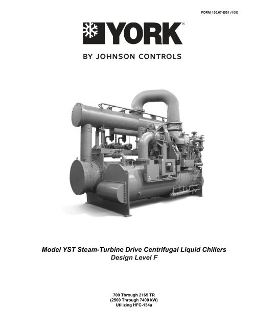
Equipment Specifications<br />
FORM 160.67-EG1 (308)<br />
GENERAL<br />
The YORK <strong>YST</strong> MaxE <strong>Centrifugal</strong> <strong>Liquid</strong> Chillers are<br />
<strong>com</strong>pletely factory-packaged including the evaporator, refrigerant<br />
condenser, <strong>com</strong>pressor, steam turbine, lubrication<br />
systems, power panel, control center, and all interconnecting<br />
unit piping and wiring. The steam condenser package<br />
is shipped separately. It is suitable for direct mounting onto<br />
the chiller or mounting along-side.<br />
The initial charge of refrigerant and oil is supplied for each<br />
chiller. When the optional refrigerant-condenser isolation<br />
valves are ordered, the unit may ship fully charged with<br />
refrigerant and oil. Actual shipping procedures will depend<br />
on a number of project-specific details.<br />
The services of a Johnson Controls factory-trained, field<br />
service representative are incurred to supervise or perform<br />
the final leak testing, charging, the initial start-up, and concurrent<br />
operator instructions.<br />
COMPRESSOR<br />
The <strong>com</strong>pressor is a single-stage centrifugal type powered<br />
by a steam turbine. The casing is fully accessible with vertical<br />
circular joints and fabricated of close-grain cast iron.<br />
The <strong>com</strong>plete operating assembly is removable from the<br />
<strong>com</strong>pressor and scroll housing.<br />
The rotor assembly consists of a heat-treated alloy steel<br />
drive shaft and impeller shaft with a high str<strong>eng</strong>th, cast<br />
aluminum alloy, fully shrouded impeller. The impeller is designed<br />
for balanced thrust and is dynamically balanced and<br />
overspeed tested for smooth, vibration-free operation.<br />
The insert-type journal and thrust bearings are fabricated<br />
of aluminum alloy. They are precision bored and axially<br />
grooved. The specially <strong>eng</strong>ineered, single helical gears with<br />
crowned teeth are designed so that more than one tooth is<br />
in contact at all times to provide even distribution of <strong>com</strong>pressor<br />
load and quiet operation. Gears are assembled in<br />
the <strong>com</strong>pressor rotor support and are film lubricated. Each<br />
gear is individually mounted in its own journal and thrust<br />
bearings to isolate it from impeller and turbine forces.<br />
CAPACITY CONTROL<br />
During part load operation at off design conditions, the<br />
chiller capacity is reduced to maintain a constant leaving<br />
chilled liquid temperature. This is ac<strong>com</strong>plished by first<br />
decreasing the speed, then closing the <strong>com</strong>pressor prerotation<br />
vanes (PRV). This reduces capacity from 100%<br />
to 15% of design for normal air conditioning applications.<br />
The speed is controlled by a pneumatically actuated governor<br />
valve which throttles the turbine inlet steam flow to<br />
maintain the speed dictated by the capacity control logic.<br />
If the tower water temperatures must be held above 75°F<br />
JOHNSON CONTROLS<br />
for other chillers, the capacity control logic automatically<br />
limits the amount of speed reduction and PRV closure<br />
to maintain stable operation. The hot gas by-pass valve<br />
is then modulated to maintain a constant leaving chilled<br />
liquid temperature with loads down to 10% of design.<br />
Rugged, airfoil shaped, cast manganese bronze vanes<br />
are precisely positioned by solid vane linkages connected<br />
to the electric actuator. The vanes are actuated by an<br />
external, electric PRV actuator.<br />
COMPRESSOR LUBRICATION S<strong>YST</strong>EM<br />
Lubrication oil is force-fed to all bearings, gears and<br />
rotating surfaces by a variable speed drive pump which<br />
operates continuously during unit operation and during<br />
coastdown. A gravity-fed oil reservoir is built into the top<br />
of the <strong>com</strong>pressor to provide lubrication during coastdown<br />
in the event of a power failure.<br />
An oil reservoir, separate from the <strong>com</strong>pressor, contains<br />
the 2 HP submersible oil pump and 3000 watt immersiontype<br />
oil heater. The oil heater is thermostatically controlled<br />
to remove refrigerant from the oil.<br />
Oil is filtered by an externally mounted 1/2 micron replaceable<br />
cartridge oil filter equipped with service valves. Oil is<br />
cooled via a shell and tube, water cooled oil cooler. It uses<br />
refrigerant condenser water as the cooling medium. The<br />
oil side of the oil cooler is provided with service valves.<br />
Oil piping is <strong>com</strong>pletely factory-installed. The water side<br />
of the oil cooler is provided with service valves, inlet<br />
strainer and solenoid valve for automatic start/stop of<br />
cooling water flow. Water piping is factory installed with<br />
customer connections conveniently brought to the edge<br />
of the chiller package and clearly tagged for installation.<br />
An automatic oil return system recovers any oil that may<br />
have migrated to the evaporator. Oil temperature control<br />
is by a three-way temperature control valve.<br />
STEAM TURBINE<br />
The steam turbine is a high efficiency multistage design<br />
operating at a maximum speed of 4500 rpm.<br />
The turbine is packaged on a driveline base and <strong>com</strong>pletely<br />
factory piped. The driveline base has a mating<br />
flange on shaft end of the package that will bolt directly<br />
to the <strong>com</strong>pressor D-flange face providing a rigid interface<br />
between turbine package and <strong>com</strong>pressor. The<br />
turbine/<strong>com</strong>pressor driveline is factory aligned prior to<br />
shipment. The turbine drive shaft is directly connected<br />
to the <strong>com</strong>pressor shaft with a flexible disc coupling. The<br />
coupling is of an all metal construction with no wearing<br />
parts assuring long life and no lubrication requirements<br />
providing low maintenance.<br />
7
Equipment Specifications - continued<br />
The turbine casing is horizontally split. It is designed to<br />
allow longitudinal thermal expansion without the affecting<br />
alignment or efficiency of the turbine. The shaft and<br />
wheels are alloy steel with the wheels shrunk and keyed<br />
to the shaft. The turbine blades are 403 grade stainless<br />
steel and the shaft is ground throughout with stainless<br />
steel sprayed in the carbon ring end gland contact area.<br />
Stainless steel steam nozzles are furnished throughout<br />
the turbine. Carbon ring-end gland and diaphragm seals<br />
are furnished. The turbine-end gland carbon-ring seals<br />
(minimum five seals per end gland) are separated by<br />
partitions of stainless steel.<br />
A inlet steam strainer is supplied. It has adequate size<br />
and mesh to minimize the pressure drop. The strainer<br />
is removable without breaking the steam piping connections<br />
and is fabricated from stainless steel.<br />
Blanket insulation is furnished on the steam chest and<br />
barrel of the turbine for operator protection and to enhance<br />
efficiency.<br />
The turbine speed is controlled by a governor valve<br />
which is integrated with the chiller controls. The valve is<br />
of stainless steel with stainless steel seats. It is designed<br />
to control flow throughout the entire operating range of<br />
the turbine. The system employs an overspeed governor<br />
designed to close an independent high performance<br />
butterfly trip valve when the turbine speed exceeds 110<br />
percent of the maximum continuous operating speed.<br />
Activation of the independent trip valve causes the governor<br />
valve to also close. A micro switch is furnished on<br />
the trip linkage for the customer’s use.<br />
TURBINE LUBRICATION S<strong>YST</strong>EMS<br />
Ring Oil Lubricated <strong>Turbine</strong>s - <strong>Drive</strong> powers less than<br />
1700Hp (1268 kW) only:<br />
The bearings are of the steel-backed, babbitt-lined,<br />
split-sleeve type. The design is such that the bottom<br />
half is removable with the shaft in place. The<br />
bearing housing has provisions for air purging of<br />
the housing shaft seals. The thrust bearing is a ball<br />
bearing type, accessible and removable without<br />
lifting the top half of the turbine casing. Oil cooling<br />
is by water cooled bearing housings.<br />
External, Pressurized Lube System <strong>Turbine</strong>s:<br />
The bearings are of the steel-backed, babbitt-lined,<br />
split-sleeve type. The design is such that the bottom<br />
half is removable with the shaft in place. The bearing<br />
housing has provisions for purging air from the<br />
housing shaft seals. The thrust bearing is a double<br />
acting, Kingsbury type. The lubrication system is<br />
integral to the turbine driveline base and <strong>com</strong>pletely<br />
factory piped. The lubrication system consists of a<br />
shaft driven main oil pump, motor driven auxiliary<br />
oil pump, water cooled shell and tube oil cooler, 25<br />
micron full flow oil filter and separate oil reservoir<br />
with level gauge. Oil temperature control is by a<br />
three way temperature control valve.<br />
STEAM CONDENSER PACKAGE<br />
A steam condenser is provided to condense exhaust<br />
steam at vacuum pressures to maintain efficient turbine<br />
operation. The steam condenser water circuit is piped<br />
in series with the refrigerant condenser, eliminating a<br />
separate cooling water circuit. It is designed to minimize<br />
pressure drop for energy savings.<br />
The steam condenser is furnished fully packaged. The<br />
package includes a single hotwell pump, a single liquid<br />
ring vacuum pump for air removal, atmospheric relief<br />
valve, and level control system. The package is factory<br />
piped, wired and mounted on a steel frame suitable for<br />
installation on the refrigerant condenser or on the floor<br />
adjacent to the chiller system.<br />
Condensate level is controlled by a level control system<br />
with two pneumatic control valves - one for recirculation<br />
and the other for removal of condensate. The liquid ring<br />
vacuum pump is capable of drawing the condenser down<br />
to operating pressure in approximately 10 minutes. The<br />
hotwell pump is a single-stage, end suction type suitable<br />
for hotwell service. The steam side is designed for 15<br />
psig (100 kPa) and 30" Hg Vac (760 mmHg).<br />
The atmospheric relief valve is a water-seal type with<br />
an external handwheel, sized in accordance with the<br />
Heat Exchange Institute Standards (HEI) for protection<br />
of the steam turbine exhaust, steam trunk, and steam<br />
condenser.<br />
All key control and monitoring parameters are integrated<br />
with the chiller control panel. In addition, auxiliary pressure<br />
gauges are located at the condenser steam inlet<br />
and condensate pump discharge piping, and temperature<br />
gauges are located at the steam inlet, cooling water inlet<br />
and outlet, and the hotwell.<br />
To facilitate rigging, condenser is separable from the<br />
skid by unbolting. Piping is outfitted with unions at<br />
suitable break-points. Both condenser and skid are<br />
outfitted with lifting lugs for both vertical and horizontal<br />
lifting.<br />
8 JOHNSON CONTROLS
FORM 160.67-EG1 (308)<br />
HEAT EXCHANGERS<br />
Shells<br />
Evaporator, refrigerant condenser and steam condenser<br />
shells are fabricated from rolled carbon steel plates with<br />
fusion welded seams. Carbon steel tube sheets, drilled<br />
and reamed to ac<strong>com</strong>modate the tubes, are welded to<br />
the end of each shell. Intermediate tube supports are<br />
fabricated from carbon steel plates, drilled and reamed to<br />
eliminate sharp edges. The refrigerant side of each shell is<br />
designed, tested, and stamped in accordance with ASME<br />
Boiler and Pressure Vessel Code, Section VIII - Division I,<br />
or other pressure vessel code as appropriate. The steam<br />
side of the steam condenser is designed in accordance<br />
with the Heat Exchange Institute (HEI), an industry standard<br />
for steam condenser technology.<br />
Tubes<br />
Refrigerant heat exchanger tubes are a high-efficiency,<br />
externally and internally enhanced type to provide optimum<br />
performance. Tubes in both the evaporator and<br />
refrigerant condenser are 3/4" O.D. (19 mm) copper alloy<br />
and utilize the “skip-fin” design, providing a smooth<br />
internal and external surface at each intermediate tube<br />
support. This provides extra wall thickness (up to twice<br />
as thick) and non-work hardened copper at the support<br />
location, extending the life of the heat exchangers. Each<br />
tube is roller-expanded into the tube sheets providing a<br />
leak-proof seal, and is individually replaceable. <strong>Steam</strong><br />
condenser tubes are copper, providing economical and<br />
efficient heat transfer.<br />
Evaporator<br />
The evaporator is a shell and tube, flooded-type heat exchanger.<br />
A distributor trough provides uniform distribution<br />
of refrigerant over the entire shell l<strong>eng</strong>th to yield optimum<br />
heat transfer. A suction baffle or aluminum mesh eliminators<br />
are located above the tube bundle to prevent liquid<br />
refrigerant carryover into the <strong>com</strong>pressor. A 1-1/2" (38<br />
mm) liquid level sight glass is conveniently located on the<br />
side of the shell to aid in determining proper refrigerant<br />
charge. The evaporator shell contains a dual-refrigerant<br />
relief-valve arrangement set at 180 psig (1241 kPa); or<br />
single relief-valve arrangement, if the chiller is supplied<br />
with the optional refrigerant isolation-valves. A 3/4" (19<br />
mm) flare male charging connection is provided.<br />
Refrigerant Condenser<br />
The refrigerant condenser is a shell and tube type, with<br />
a discharge-gas baffle to prevent direct high velocity impingement<br />
on the tubes. The baffle is also used to distribute<br />
the refrigerant gas flow properly for most efficient heat<br />
transfer. An integral sub-cooler is located at the bottom of<br />
the refrigerant condenser shell providing highly effective<br />
liquid refrigerant subcooling to provide the highest cycle<br />
efficiency. The refrigerant condenser contains dual refrigerant<br />
relief valves set at 235 psig (1620 kPa).<br />
<strong>Steam</strong> Condenser<br />
<strong>Steam</strong> condenser construction is of the shell and tube<br />
type of welded steel construction with 3/4" OD (19 mm)<br />
copper tubes, roller-expanded into tube sheets. An impingement<br />
plate located below the centrally located steam<br />
inlet redirects steam flow to protect the tubes from high<br />
velocity steam. Subcooling sections in the condenser<br />
cool non-condensibles sufficiently below the condensing<br />
temperature thereby reducing the vacuum pump capacity<br />
required. The water side is suitable for a maximum working<br />
pressure of 150 psig (1030 kPa). An atmospheric relief<br />
valve, sized per HEI to protect the condenser, is included.<br />
This relief valve is set to open at 1-2 psig (7-14 kPa) and<br />
will prevent pressure in the condenser shell from exceeding<br />
10 psig (69 kPa). Seal water is required to maintain a<br />
liquid seal in the valve. An inlet and overflow connection<br />
is provided on the valve for this purpose.<br />
Water Boxes<br />
The water boxes are fabricated from steel and are marine<br />
style (<strong>com</strong>pact or marine available on evaporator). The<br />
standard design working pressure is 150 psig (1030 kPa)<br />
and the chiller boxes are tested at 225 psig (1550 kPa).<br />
<strong>Steam</strong> condenser boxes are tested at 215 psig (1480kPa).<br />
Integral steel water baffles are located and welded within<br />
the water box to provide the required pass arrangements.<br />
Stub-out water nozzle connections with grooves are<br />
welded to the water boxes. These nozzle connections<br />
are suitable for ANSI/AWWA C-606 couplings, welding<br />
or flanges, and are capped for shipment. Plugged 3/4"<br />
NPTI (19 mm) drain and vent connections are provided<br />
in each water box.<br />
REFRIGERANT FLOW CONTROL<br />
Refrigerant flow to the evaporator is controlled by the<br />
YORK variable orifice control system. The liquid refrigerant<br />
level is continuously monitored to provide optimum<br />
subcooler, refrigerant condenser and evaporator performance.<br />
The variable orifice electronically adjusts to all<br />
Real-World operating conditions, providing the most efficient<br />
and reliable operation of refrigerant flow control.<br />
POWER PANEL<br />
All motor contactors and circuit protectors, the <strong>com</strong>pressor<br />
oil pump variable speed drive and the control power transformer<br />
are contained in an enclosure installed adjacent to the<br />
OptiView control center. A main power disconnect switch is<br />
supplied which provides the termination points for customer’s<br />
single point power supply wiring.<br />
OPTIVIEW CONTROL CENTER<br />
JOHNSON CONTROLS<br />
9
Equipment Specifications - continued<br />
General<br />
The chiller is controlled by a stand-alone microprocessor<br />
based control center. The chiller control panel provides<br />
control of entire system, including turbine and steam<br />
condenser operation and monitoring.<br />
The control panel includes a 10.4". diagonal color liquid<br />
crystal display (LCD) surrounded by “soft” keys which are<br />
redefined based on the screen displayed at that time. The<br />
display is mounted in the middle of a keypad interface and<br />
protected by a locked enclosure. The screen details all<br />
operations and parameters, using a graphical representation<br />
of the chiller and its major <strong>com</strong>ponents. Panel text is<br />
in English only. Data can be displayed in either English<br />
or Metric units. Additional features are:<br />
• Smart Freeze Point Protection capable of running<br />
the chiller at 36°F (2.2°C) leaving chilled water<br />
temperature eliminating nuisance trips on low water<br />
temperature. The sophisticated program and sensors<br />
monitor the chiller water and evaporator refrigerant<br />
liquid temperatures to prevent freeze-up.<br />
• The panel displays countdown timer messages so the<br />
operator knows when functions are starting and stopping.<br />
Every programmable point has a pop-up screen<br />
with the allowable ranges, so that the chiller can not be<br />
programmed to operate outside of its design limits.<br />
• Security access is built in to prevent unauthorized<br />
change of setpoints, to allow local or remote control<br />
of the chiller, and to allow manual operation of the<br />
pre-rotation vanes and oil pump. Access is through ID<br />
and password recognition, which is defined by three<br />
different levels of user <strong>com</strong>petence: view, operator,<br />
and service.<br />
• Trending data is available with the ability to customize<br />
points from once every second to once every hour.<br />
The panel will trend up to 6 different parameters from<br />
a list of over 140, without the need of an external<br />
monitoring system.<br />
• The operating program is stored in non-volatile<br />
memory to eliminate reprogramming the chiller due to<br />
AC power failure or battery discharge. Programmed<br />
setpoints are retained in lithium-battery-backed RTC<br />
memory for a minimum of 11 years with power removed<br />
from the system.<br />
• Includes an RS-232 port to output all system operating<br />
data, shutdown/cycling message, and a record of the<br />
last 10 cycling or safety shutdowns to a field-supplied<br />
printer. Data logs to a printer at a set programmable<br />
interval. This data can be pre-programmed to print<br />
from 1 minute to 1 day.<br />
• The text displayed within the system status and system<br />
details field is displayed as a color-coded message<br />
to indicate severity: red for safety fault, orange<br />
for cycling faults, yellow for warnings, and green for<br />
normal messages.<br />
The chiller control panel provides a multitude of diagnostic<br />
and operating data too numerous to cover <strong>com</strong>pletely in<br />
this guide. However, a general description of some of<br />
the data available and examples of the various screens<br />
provided follows:<br />
Some highlights (not all inclusive) of the data available<br />
on the panel are as follows:<br />
System Operating Information<br />
Evaporator<br />
• Leaving and return chilled water temperature<br />
• Refrigerant liquid temperature - evaporator<br />
• Evaporator pressure<br />
• Hot gas control status<br />
• Chilled water flow<br />
Refrigerant Condenser<br />
• Entering and leaving refrigerant condenser water<br />
temperature<br />
• Refrigerant liquid temperature - refrigerant condenser<br />
• Refrigerant condenser pressure<br />
• Subcooler refrigerant liquid level<br />
• Subcooler refrigerant liquid level control status<br />
• Refrigerant condenser water flow<br />
Compressor<br />
• Compressor discharge temperature<br />
• Compressor oil temperature<br />
• Compressor supply oil pressure<br />
• Compressor thrust bearing proximity probe gap (J<br />
<strong>com</strong>pressors only)<br />
• Pre-rotation vanes (PRV) position<br />
<strong>Steam</strong> <strong>Turbine</strong><br />
• <strong>Turbine</strong> shaft end bearing temperature<br />
• <strong>Turbine</strong> governor end bearing temperature<br />
• <strong>Turbine</strong> inlet steam temperature<br />
• <strong>Turbine</strong> inlet steam pressure<br />
• <strong>Turbine</strong> first stage steam pressure<br />
• <strong>Turbine</strong> exhaust pressure<br />
• <strong>Turbine</strong> speed<br />
• <strong>Turbine</strong> governor control status<br />
<strong>Steam</strong> Condenser<br />
• Hotwell condensate level<br />
• Hotwell level control status<br />
10 JOHNSON CONTROLS
FORM 160.67-EG1 (308)<br />
Safety shutdowns<br />
(will prevent unit from starting or operating)<br />
• Evaporator - low pressure<br />
• Evaporator - low temperature (Smart Freeze Point<br />
Protection)<br />
• Evaporator - transducer or leaving liquid probe failure<br />
• Evaporator - transducer or temperature sensor failure<br />
• Refrigerant condenser - high pressure contacts<br />
open<br />
• Refrigerant condenser - high pressure<br />
• Refrigerant condenser - pressure transducer out-ofrange<br />
• Compressor discharge - high temperature<br />
• Compressor discharge - low temperature<br />
• Compressor oil -high temperature<br />
• Compressor oil - low differential temperature<br />
• Compressor oil - high differential pressure<br />
• Compressor oil - sump pressure transducer out-ofrange<br />
• Compressor oil - differential pressure calibration<br />
• Compressor oil - variable speed pump - pressure<br />
setpoint not achieved<br />
• Compressor thrust bearing - proximity probe uncalibrated<br />
(J <strong>com</strong>pressors only)<br />
• Compressor thrust bearing - proximity probe clearance<br />
(J <strong>com</strong>pressors only)<br />
• Compressor thrust bearing - proximity probe out-ofrange<br />
(J <strong>com</strong>pressors only)<br />
• Control panel - power failure<br />
• <strong>Turbine</strong> governor end bearing high temperature<br />
• <strong>Turbine</strong> shaft end bearing high temperature<br />
• <strong>Turbine</strong> oil - low pressure<br />
• <strong>Turbine</strong> oil - high temperature<br />
• <strong>Turbine</strong> underspeed<br />
• <strong>Turbine</strong> exhaust high pressure<br />
• Standby hotwell pump fault (warning on failure of<br />
primary pump)<br />
• Standby vacuum pump - no sealing water flow (warning<br />
on failure of primary system)<br />
• Standby vacuum pump fault (warning on failure of<br />
primary pump)<br />
• Hotwell condensate high level<br />
• Hotwell condensate low level<br />
Services<br />
• Expansion Joint Manufacturers Assoc., Inc. (EJMA)<br />
• ARI Standard 550/590<br />
• ASHRAE 15 - Safety Code for Mechanical Refrigeration<br />
• ASHRAE Guideline 3 - Reducing Emission of Halogenated<br />
Refrigerants in Refrigeration and Air-Conditioning<br />
Equipment and Systems<br />
• N.E.C. - National Electrical Code<br />
• OSHA - Occupational Safety and Health Act<br />
ISOLATION MOUNTING<br />
The unit is provided with four vibration isolation mounts<br />
consisting of 1" (25.4 mm) thick neoprene isolation pads<br />
for field mounting under the steel mounting plates located<br />
on the tube sheets.<br />
REFRIGERANT CONTAINMENT<br />
The refrigerant circuit has been designed as a factorypackaged<br />
system. As such, it has minimum joints from<br />
which refrigerant can leak. The entire assembly has been<br />
thoroughly leak tested at the factory prior to shipment.<br />
The YORK chiller includes service valves conveniently<br />
located to facilitate transfer of refrigerant to a remote<br />
refrigerant storage/recycling system. Optional refrigerant<br />
condenser isolation valves allow storage of the charge in<br />
the refrigerant condenser.<br />
PAINT<br />
Exterior surfaces are protected with one coat of Caribbean<br />
blue, durable alkyd-modified, vinyl enamel, machinery<br />
paint.<br />
SHIPMENT<br />
Protective covering is furnished on the control center.<br />
Water nozzles are capped with fitted plastic enclosures.<br />
Entire unit is protected with industrial-grade, reinforced<br />
shrink-wrapped covering.<br />
CODES AND STANDARDS<br />
• ASME Boiler and Pressure Vessel Code - Section Vlll<br />
Division 1.<br />
• Heat Exchange Institute (HEI), Industry Standard for<br />
<strong>Steam</strong> Condensers<br />
• NEMA (SM23) <strong>Steam</strong> <strong>Turbine</strong>s for Mechanical <strong>Drive</strong><br />
JOHNSON CONTROLS<br />
11
Accessories and Modifications<br />
FLOOR MOUNTED STEAM CONDENSER<br />
As an alternative to the standard packaged location, the<br />
steam condenser package can be ordered for floor mounting<br />
adjacent to the chiller package. Prefabricated piping<br />
kits for the steam trunk, water piping and wiring between<br />
chiller package and steam condenser are not included<br />
with a floor mounted arrangement. These interconnecting<br />
<strong>com</strong>ponents must be designed, supplied and installed<br />
by customer.<br />
Note: Interconnecting <strong>com</strong>ponents may be ordered<br />
through the factory via a special quote upon request (site<br />
arrangement details will be required at time of request<br />
for quote).<br />
AUTO-START CONTROL FEATURES<br />
When this option is ordered, the chiller is provided with all<br />
<strong>com</strong>ponents and programming for the OptiView micropanel<br />
to automatically control the start-up and shutdown of the<br />
system. All solenoids and automated <strong>com</strong>ponents necessary<br />
for full automation are provided. Some parts will ship<br />
loose for installation at job site. An automatic pressure<br />
powered pump is also provided for draining condensate<br />
from the steam turbine casing during operation.<br />
DUAL PUMPS FOR STEAM CONDENSER PACKAGE<br />
Factory installed secondary (100% standby duty) condensate<br />
and vacuum pumps, including all interconnecting<br />
piping is available. Automatic switchover to a standby<br />
pump in the event of a primary pump failure is included<br />
in this option.<br />
STEAM TURBINE CASING DRAIN OPTIONS<br />
The steam turbine casing must be provided with a means<br />
of draining during operation (while under vacuum). Factory<br />
options available for this function are:<br />
• Automatic pressure powered pump<br />
• Manual condensate drain tank (by special quote)<br />
• Automatic condensate drain tank (by special quote)<br />
Casing drain equipment is shipped loose for installation<br />
at job site.<br />
FACTORY INSULATION<br />
Factory-applied thermal insulation of the flexible, closedcell<br />
neoprene type, 3/4" (19 mm) thick is attached with<br />
vapor-proof cement to the evaporator shell, flow chamber,<br />
tube sheets, suction connection, and (as necessary)<br />
to the auxiliary tubing. Not included is the insulation of<br />
<strong>com</strong>pact water boxes and nozzles. This insulation will<br />
normally prevent condensation in environments with<br />
relative humidities up to 75% and dry bulb temperatures<br />
ranging from 50° to 90°F (10° to 32°C). 1-1/2" (38 mm)<br />
thick insulation is also available for relative humidities up<br />
to 90% and dry bulb temperatures ranging from 50° to<br />
90°F (10° to 32°C).<br />
The turbine steam chest is insulated with a custom fitted,<br />
fiberglass insulating blanket for protection of personnel<br />
and enhancement of efficiency.<br />
WATER FLANGES<br />
150 psig (1030 kPa) ANSI raised-face flanges for refrigerant<br />
condenser, evaporator and steam condenser<br />
water connections, are factory-welded to water nozzles.<br />
Companion flanges, bolts, nuts and gaskets are not<br />
included.<br />
MARINE WATER BOXES<br />
Marine water boxes allow service access for cleaning of<br />
the heat exchanger tubes without the need to break the<br />
water piping. Bolted-on covers are arranged for convenient<br />
access. Victaulic nozzle connections are standard;<br />
flanges are optional. Marine water boxes are available for<br />
the evaporator (limited arrangements only).<br />
Note: Marine water boxes are standard scope of supply on the<br />
refrigerant and steam condensers.<br />
KNOCK-DOWN SHIPMENT<br />
The chiller can be shipped knocked down into major subassemblies<br />
(evaporator, refrigerant condenser, driveline,<br />
etc.) as required to rig into tight spaces. This is particularly<br />
convenient for existing buildings where equipment<br />
room access does not allow rigging a factory-packaged<br />
chiller.<br />
NOTE: Vertical rigging of <strong>com</strong>ponents not allowed unless special<br />
design is ordered by special quote (SQ).<br />
REFRIGERANT ISOLATION VALVES<br />
Optional factory-installed isolation valves in the <strong>com</strong>pressor<br />
discharge line and refrigerant liquid line are available.<br />
This allows isolation and storage of the refrigerant charge<br />
in the chiller refrigerant condenser during servicing, eliminating<br />
time-consuming transfers to remote storage vessels.<br />
Both valves are positive shut-off, assuring integrity<br />
of the storage system.<br />
300 PSIG WATERSIDE DESIGN PRESSURE<br />
Applications with greater than 150 psig (1030 kPa) water<br />
pressure can be ac<strong>com</strong>modated by special quote upon<br />
request. Special design required for all heat exchanger<br />
12 JOHNSON CONTROLS
FORM 160.67-EG1 (308)<br />
water boxes and turbine/<strong>com</strong>pressor cooling water circuits.<br />
BAS NETWORK INTERFACE<br />
A <strong>com</strong>munication interface permitting <strong>com</strong>plete exchange<br />
of chiller data with any BAS System is available with optional<br />
ISN MicroGateway. The Micro-Gateway also allows<br />
a BAS System to issue <strong>com</strong>mands to the chiller to control<br />
its operation. All control data points are accessible to the<br />
BAS System. For full list of points, contact a Johnson<br />
Controls Representative.<br />
REFRIGERANT STORAGE / RECYCLING S<strong>YST</strong>EM<br />
A refrigerant storage/recycling system is a self-contained<br />
package consisting of a refrigerant <strong>com</strong>pressor with oil<br />
separator, storage receiver, water-cooled condenser, filter<br />
drier and necessary valves and hoses to remove, replace<br />
and distill refrigerant. All necessary controls and safety<br />
devices are a permanent part of the system. Typically not<br />
required if unit isolation valves are provided.<br />
JOHNSON CONTROLS<br />
13
Application Data<br />
The following discussion is a user’s guide in the application<br />
and installation of <strong>YST</strong> MaxE chillers to ensure the<br />
reliable, trouble-free life for which this equipment was<br />
designed. While this guide is directed towards normal,<br />
water-chilling applications, the Johnson Controls sales<br />
representative can provide <strong>com</strong>plete re<strong>com</strong>mendations<br />
on other types of applications.<br />
LOCATION<br />
<strong>YST</strong> MaxE chillers are virtually vibration free and may<br />
generally be located at any level in a building where<br />
the construction will support the total system operating<br />
weight.<br />
The unit site must be a floor, mounting pad or foundation<br />
which is level within 1/4" (6 mm) and capable of supporting<br />
the operating weight of the unit.<br />
Sufficient clearance to permit normal service and maintenance<br />
work should be provided all around and above the<br />
unit. Additional space should be provided at one end of the<br />
unit to permit cleaning of evaporator, refrigerant condenser<br />
and steam condenser tubes, as required. A doorway or<br />
other properly located opening may be used.<br />
The chiller is designed to be installed in an indoor location<br />
where temperatures range from 40°F to 104°F (4.4°C to<br />
40°C).<br />
WATER piping<br />
Flow Rate - For normal water chilling duty, evaporator and<br />
refrigerant condenser flow rates are permitted at water<br />
velocity levels in the heat exchangers tubes of between<br />
3 ft/sec and 12 ft/sec (0.9 m/s and 3.7 m/s). Variable flow<br />
applications are possible, however, chiller selections must<br />
be made using a water velocity within the range noted<br />
above. Variable flow in the refrigerant condenser is not<br />
re<strong>com</strong>mended, as it generally raises the energy consumption<br />
of the system by keeping the refrigerant condenser<br />
pressure high in the chiller. Additionally, the rate of fouling<br />
in the refrigerant condenser will increase at lower water<br />
velocities associated with variable flow, raising system<br />
maintenance costs. Cooling towers typically have narrow<br />
ranges of operation with respect to flow rates and will be<br />
more effective with full design flow. Refer to Table 1 for<br />
flow limits.<br />
Temperature Ranges - For normal water chilling duty,<br />
leaving chilled water temperatures may be selected<br />
between 38°F (3.3°C) [36°F (2.2°C) with Smart Freeze<br />
enabled] and 70°F (21°C) for water temperature ranges<br />
between 3°F and 30°F (1.7°C and 16.7°C).<br />
Water Quality – The practical and economical application<br />
of liquid chillers requires that the quality of the water<br />
supply for the condensers and evaporator be analyzed by<br />
a water treatment specialist. Water quality may affect the<br />
performance of any chiller through corrosion, deposition<br />
of heat-resistant scale, sedimentation or organic growth.<br />
These will degrade chiller performance and increase operating<br />
and maintenance costs. Normally, performance<br />
may be maintained by corrective water treatment and<br />
periodic cleaning of tubes. If water conditions exist which<br />
cannot be corrected by proper water treatment, it may be<br />
necessary to provide a larger allowance for fouling, and/or<br />
to specify special materials of construction.<br />
General Piping – All chilled water and condenser water<br />
piping should be designed and installed in accordance<br />
with accepted piping practice. Chilled water and condenser<br />
water pumps should be located to discharge<br />
through the chiller to assure positive pressure and flow<br />
through the unit. Piping should include offsets to provide<br />
flexibility and should be arranged to prevent drainage of<br />
water from the evaporator and condenser when the pumps<br />
are shut off. Piping should be adequately supported and<br />
braced independently of the chiller to avoid the imposition<br />
of strain on chiller <strong>com</strong>ponents. Hangers must allow<br />
for alignment of the pipe. Isolators in the piping and in<br />
the hangers are highly desirable in achieving sound and<br />
vibration control.<br />
Convenience Considerations – To facilitate the performance<br />
of routine maintenance work, some or all of<br />
the following steps may be taken by the purchaser: heat<br />
exchanger water boxes are equipped with plugged vent<br />
and drain connections. If desired, vent and drain valves<br />
may be installed with or without piping to an open drain.<br />
Pressure gauges with stop cocks and stop valves may<br />
be installed in the inlets and outlets of the condensers<br />
and chilled water line as close as possible to the chiller.<br />
An overhead monorail or beam may be used to facilitate<br />
servicing.<br />
Connections – The standard chiller is designed for 150<br />
psig (1030 kPa) design working pressure in both the<br />
chilled water and condenser water circuits. The connections<br />
(water nozzles) to these circuits are furnished with<br />
grooves for Victaulic couplings. Piping should be arranged<br />
for ease of disassembly at the unit for tube cleaning. All<br />
water piping should be thoroughly cleaned of all dirt and<br />
debris before final connections are made to the chiller.<br />
Chilled Water – A water strainer of maximum 1/8" (3 mm)<br />
perforated holes must be field-installed in the chilled water<br />
inlet line as close as possible to the chiller. If located close<br />
enough to the chiller, the chilled water pump may be protected<br />
by the same strainer. The loss or severe reduction<br />
of water flow due to tube blockage could seriously impair<br />
the chiller performance or even result in tube freeze-up.<br />
14 JOHNSON CONTROLS
FORM 160.67-EG1 (308)<br />
Condenser Water – The chiller is <strong>eng</strong>ineered for maximum<br />
efficiency at both design and part load operation<br />
by taking advantage of the colder cooling tower water<br />
temperatures which naturally occur during the winter<br />
months. Appreciable power savings are realized from<br />
these reduced heads.<br />
The minimum entering condenser water temperature is<br />
provided by the following equation:<br />
In °F: minCondWT = LChilledWT - CondRange x (PCT-<br />
Load/100) + 5 + 12 x (PctLoad/100)<br />
In °C: minCondWT = LChilledWT - CondRange x (PCT-<br />
Load/ 100) + (5 + 12 x (PctLoad/100))/1.8<br />
where:<br />
minCondWT = entering condenser water temperature<br />
LChilledWT = leaving chilled water temperature<br />
CondRange = condenser water temperature range at<br />
design.<br />
PCTLoad = chiller load as % design<br />
At initial startup, entering condensing water temperature<br />
may be as much as 25°F (14°C) colder than the standby<br />
chilled water temperature as long as it is above the minimum<br />
entering condenser water temperature allowed.<br />
A water strainer of maximum 1/8" (3 mm) perforated holes<br />
is re<strong>com</strong>mended to be field-installed in the refrigerant condenser<br />
water inlet line as close as possible to the chiller.<br />
If located close enough to the chiller, the condenser water<br />
pump may be protected by the same strainer. The loss or<br />
severe reduction of water flow due to tube blockage could<br />
seriously impair the chiller performance.<br />
STEAM AND CONDENSATE PIPING<br />
<strong>Turbine</strong> supply steam and condensate piping connections<br />
to the chiller are to be supplied and installed by the site<br />
piping contractor. In addition, the turbine exhaust to the<br />
steam condenser shall be installed by the piping contractor,<br />
however, the design and supply of <strong>com</strong>ponents<br />
may be supplied by Johnson Controls depending on the<br />
options chosen. Piping should be adequately supported<br />
and braced independently of the chillers. Hangers must<br />
allow for piping alignment at the operation temperature.<br />
Piping contractor is responsible for the fit and form of the<br />
turbine steam piping. The piping must be installed with<br />
the flanges and bolt holes properly aligned. The bolts<br />
should be able to be inserted without any difficulty and no<br />
force should be applied to allow the bolts to be inserted<br />
or flanges aligned. When the flange bolts are tightened,<br />
JOHNSON CONTROLS<br />
they must not impose any force or moment on the turbine<br />
flanges. Contact your local Johnson Controls office for any<br />
additional information.<br />
RELIEF PIPING<br />
Refrigerant Relief<br />
Each chiller is equipped with dual pressure relief valves<br />
on the refrigerant condenser and two dual relief valves on<br />
the evaporator, or two single relief valves on the evaporator<br />
if the optional refrigerant isolation valves are ordered.<br />
The dual relief valves on the refrigerant condenser are<br />
redundant and allow changing of either valve while the<br />
unit is fully charged. The purpose of the relief valves is to<br />
quickly relieve excess pressure of the refrigerant charge<br />
to the atmosphere, as a safety precaution in the event of<br />
an emergency such as fire. They are set to relieve at an<br />
internal pressure as noted on the pressure vessel data<br />
plate, and are provided in accordance with ASHRAE 15<br />
safety code and ASME or applicable pressure vessel<br />
code.<br />
Sized to the requirements of applicable codes, a vent line<br />
must run from the relief device to the outside of the building.<br />
This refrigerant relief piping must include a cleanable,<br />
vertical-leg dirt trap to catch vent-stack condensation.<br />
Vent piping must be arranged to avoid imposing a strain<br />
on the relief connection and should include one flexible<br />
connection.<br />
<strong>Steam</strong> Relief<br />
Each steam condenser is equipped with an atmospheric<br />
relief valve, sized to relieve all the steam which can be<br />
admitted to a turbine under maximum possible full throttle<br />
conditions. The atmospheric relief valve is designed/<br />
selected per HEI standards for steam condensers and<br />
provides protection for the steam turbine exhaust and<br />
exhaust trunk, as well as the steam condenser shell.<br />
The discharge of the atmospheric relief valve should be<br />
piped to direct a large volumetric flow of hot steam to a<br />
safe area, away from all personnel.<br />
SOUND AND VIBRATION CONSIDERATIONS<br />
A <strong>YST</strong> MaxE chiller is not a source of objectionable sound<br />
and vibration in normal air conditioning applications.<br />
Neoprene isolation mounts are furnished as standard<br />
with each unit.<br />
<strong>YST</strong> MaxE chiller sound pressure level ratings will be<br />
furnished on request.<br />
Control of sound and vibration transmission must be taken<br />
into account in the equipment room construction as well<br />
as in the selection and installation of the equipment.<br />
15
Application Data - continued<br />
THERMAL INSULATION<br />
No appreciable operating economy can be achieved by<br />
thermally insulating the chiller. However, the chiller's cold<br />
surfaces should be insulated with a vapor barrier insulation<br />
sufficient to prevent condensation. A chiller can be<br />
factory-insulated with 3/4" (19 mm) or 1-1/2" (38 mm)<br />
thick insulation, as an option. This insulation will normally<br />
prevent condensation in environments with dry bulb<br />
temperatures of 50°F to 90°F (10°C to 32°C) and relative<br />
humidities up to 75% [3/4" (19 mm) thickness] or 90% [1-<br />
1/2" (38 mm) thickness]. The insulation is painted and the<br />
surface is flexible and reasonably resistant to wear. It is<br />
intended for a chiller installed indoors and, therefore, no<br />
protective covering of the insulation is usually required.<br />
If insulation is applied to the water boxes at the job site,<br />
it must be removable to permit access to the tubes for<br />
routine maintenance. The turbine steam chest is factory<br />
insulated with a custom fitted, fiberglass insulating blanket<br />
for protection of personnel. The blanket is removable for<br />
maintenance access to the turbine.<br />
VENTILATION<br />
The ASHRAE Standard 15 Safety Code for Mechanical<br />
Refrigeration requires that all machinery rooms be vented<br />
to the outdoors utilizing mechanical ventilation by one or<br />
more power-driven fans. This standard, plus National<br />
Fire Protection Association Standard 90A, state, local and<br />
any other related codes should be reviewed for specific<br />
requirements. Since the <strong>YST</strong> MaxE chiller uses steam,<br />
ventilation should allow for the removal of heat radiated<br />
from the steam turbine.<br />
In addition, the ASHRAE Standard 15 requires a refrigerant<br />
vapor detector to be employed for all refrigerants. It<br />
is to be located in an area where refrigerant from a leak<br />
would be likely to concentrate. An alarm is to be activated<br />
and the mechanical ventilation started at a value<br />
no greater than the TLV (Threshold Limit Value) of the<br />
refrigerant.<br />
CUSTOMER CONNECTIONS/INTERFACES<br />
(see product drawings for connection sizes)<br />
Water/Drains<br />
• Refrigerant condenser inlet/outlet*<br />
• Evaporator inlet/outlet<br />
• <strong>Turbine</strong>/Compressor cooling water manifold inlet/outlet<br />
• <strong>Steam</strong> condenser inlet*/outlet<br />
• <strong>Steam</strong> condenser vacuum pump seal water: 3.5 gpm<br />
(0.2 L/s) @ approx. 60°F (15.6 °C)<br />
• <strong>Steam</strong> condenser vacuum pump discharge separator<br />
vent and drain<br />
• <strong>Steam</strong> condenser relief valve seal water: trickle flow<br />
• <strong>Steam</strong> condenser relief valve seal water drain<br />
• <strong>Steam</strong> turbine casing drain<br />
• <strong>Steam</strong> turbine gland leak off drain<br />
• <strong>Steam</strong> turbine steam ring drain<br />
• <strong>Steam</strong> condenser condensate overboard valve: [note:<br />
approx. 20 psig (138 kPa) discharge pressure available<br />
at outlet of overboard valve. If downstream pressure<br />
requirements exceed this, a custom condensate<br />
pump selection is required.]<br />
• <strong>Steam</strong> condenser hotwell level system drain<br />
• Water box vents and drains - evaporator, refrigerant<br />
condenser and steam condenser<br />
<strong>Steam</strong>/Vents<br />
• <strong>Steam</strong> turbine steam inlet<br />
• <strong>Steam</strong> turbine steam exhaust*<br />
• <strong>Steam</strong> condenser steam inlet*<br />
• <strong>Steam</strong> condenser relief valve vent<br />
• <strong>Steam</strong> turbine gland sealing steam: 150 psig (1030<br />
kPa) max. steam supply<br />
• <strong>Steam</strong> turbine gland seal relief valve<br />
Refrigerant Connections<br />
• Refrigerant drain/charging connection<br />
• Refrigerant transfer/service connections<br />
• Refrigerant condenser relief valves(s)<br />
• Evaporator relief valve(s)<br />
Air (Instrument Quality Air Source - ISA S7.3)<br />
• <strong>Steam</strong> turbine governor air supply and bearing seal<br />
air purge: 80-150 psig (552 - 1030 kPa), approx. 13<br />
SCFM (22 sm3/h).<br />
• <strong>Steam</strong> condenser level control system: 20-150 psig<br />
(138 - 1030 kPa), approx. 0.5 SCFM (0.9 sm3/h).<br />
Power<br />
• 460V single point power connection, approximately<br />
28.6 KVA (KD turbine) or 24.2 KVA (KG turbine).<br />
Required Auxiliary Components (customer supplied)<br />
• <strong>Steam</strong> inlet strainer: Full flow strainer with fine [3/64"<br />
(1.2 mm) perforations], stainless steel mesh, suitable<br />
for steam service.<br />
• <strong>Steam</strong> inlet moisture separator: <strong>Steam</strong> supply to<br />
turbine must be dry & saturated for optimum efficiency.<br />
• <strong>Steam</strong> inlet throttling valve: Manual globe valve for<br />
* Johnson Controls provided pre-fabricated piping for these connections<br />
16 JOHNSON CONTROLS
FORM 160.67-EG1 (308)<br />
TABLE 1 – WATER FLOW RATE LIMITS (GPM) — BASED UPON STANDARD TUBES @ DESIGN FULL<br />
LOAD CONDITIONS<br />
Evaporator<br />
Condenser<br />
<strong>Model</strong> 1 Pass 2 Pass 3 Pass <strong>Model</strong> 1 Pass 2 Pass 3 Pass<br />
Min Max Min Max Min Max Min Max Min Max Min Max<br />
HF 1981 7921 991 3336 660 2224 GB 2826 10179 1413 4277 – –<br />
HH 2330 9318 1165 3863 777 2590 GD 3313 11935 1657 4936 – –<br />
JF 2738 10949 1369 4552 913 3069 HB 3851 13873 1926 5823 – –<br />
JG 2961 11841 1481 4885 987 3305 HD 4176 15044 2088 6264 – –<br />
JH 3182 12721 1591 5198 1061 3529 JB 4782 17226 2391 7059 – –<br />
TF 2738 10949 1369 4552 913 2880 JD 5313 19140 2657 7722 – –<br />
TG 2961 11841 1481 4591 987 3101 TB 4782 17226 2391 8614 – –<br />
TH 3182 12721 1591 4896 1061 3318 TD 5313 19140 2657 7267 – –<br />
VF 3507 14023 1754 5480 1169 3634 VB 6075 21883 3037 8417 – –<br />
VH 3836 15338 1918 5947 1279 3947 VD 6792 24467 3396 9280 – –<br />
– – – – – – – – – – – – – –<br />
WF 4382 17520 2191 6851 1461 4524 – – – – – – –<br />
WH 5113 20442 2556 7886 1704 5214 – – – – – – –<br />
inlet steam isolation and throttling (during start up).<br />
Note: This valve is Johnson Controls supplied when<br />
the system auto-start option is ordered.<br />
• <strong>Steam</strong> turbine casing drain options: The steam turbine<br />
casing must be provided with a means of draining<br />
during operation (while under vacuum). Customer<br />
options for this function are an automatic pressure<br />
powered pump, a manual condensate drain tank or<br />
an automatic condensate drain tank.<br />
Note: An automatic pressure powered pump is Johnaon Controls<br />
supplied when the system auto-start option is ordered.<br />
JOHNSON CONTROLS<br />
17
Application Data - continued<br />
TABLE 1A – WATER FLOW RATE LIMITS (L/S) — BASED UPON STANDARD TUBES @ DESIGN FULL<br />
LOAD CONDITIONS<br />
Evaporator<br />
Condenser<br />
<strong>Model</strong> 1 Pass 2 Pass 3 Pass <strong>Model</strong> 1 Pass 2 Pass 3 Pass<br />
Min Max Min Max Min Max Min Max Min Max Min Max<br />
HF 125 500 62 210 42 140 GB 178 642 89 270 – –<br />
HH 147 588 74 244 49 163 GD 209 753 105 311 – –<br />
JF 173 691 86 287 58 194 HB 243 875 121 367 – –<br />
JG 187 747 93 308 62 209 HD 263 949 132 395 – –<br />
JH 201 803 100 328 67 223 JB 302 1087 151 445 – –<br />
TF 173 691 86 270 58 182 JD 335 1208 168 487 – –<br />
TG 187 747 93 290 62 196 TB 302 1087 151 543 – –<br />
TH 201 803 100 309 67 249 TD 335 1208 168 458 – –<br />
VF 221 885 111 346 74 229 VB 383 1381 192 531 – –<br />
VH 242 988 121 375 81 249 VD 429 1544 214 585 – –<br />
– – – – – – –<br />
WF 276 1105 138 432 92 285 – – – – – – –<br />
WF 323 1290 161 498 108 329 – – – – – – –<br />
18 JOHNSON CONTROLS
Application Data - continued<br />
FORM 160.67-EG1 (308)<br />
TABLE 2 – AVAILABLE COMPRESSOR/SHELL/TURBINE/STEAM CONDENSER MODELS<br />
COMPRESSOR CODE EVAPORATOR CODE CONDENSER CODE TURBINE MODEL STEAM CONDENSER MODEL<br />
K2G51000090<br />
29168A<br />
J1 HF, HH GB, GD<br />
K2G51000125<br />
29168B<br />
K2G71000090<br />
29168C<br />
K2G71000125<br />
29168D<br />
J2<br />
HF, HH<br />
GB, GD<br />
HB, HD<br />
J3 JF, JG, JH JB, JD<br />
J4<br />
KG81250090<br />
K2G71250125<br />
KG81620090<br />
K2G71620125<br />
KD71620090<br />
KD71620125<br />
TF, TG, TH TB, TD KD71620090<br />
VF, VH<br />
VB, VD<br />
KD71620125<br />
KD71750090<br />
WF, WH<br />
VB, VD<br />
KD71750125<br />
31168B<br />
31168C<br />
31168D<br />
35168B<br />
35168C<br />
35168D<br />
33192B<br />
33192C<br />
33192D<br />
JOHNSON CONTROLS<br />
19
Top Mtd. Unit Dimensions - (Ft. - In.)<br />
J COMPRESSOR UNITS<br />
APPROX. OVERALL HEIGHT<br />
F<br />
SEE NOTE 4<br />
TURBINE<br />
STEAM<br />
CONDENSER<br />
PACKAGE<br />
L<br />
M<br />
E<br />
EVAPORATOR<br />
CONDENSER<br />
NOTE 3<br />
C<br />
NOTE 3<br />
H G H<br />
APPROX. OVERALL WIDTH<br />
J<br />
J1 COMPRESSOR (H-G SHELLS)<br />
KG STEAM TURBINE /<br />
29168 STEAM CONDENSER<br />
DIMENSION CODE FT-INCHES<br />
A 8'–11 1/4"<br />
B 7'–10 1/2"<br />
C 2'–2 1/4"<br />
D<br />
1'–9"<br />
E W/4" STEAM INLET 6'–11 3/4"<br />
E W/6" STEAM INLET 6'–10 1/2"<br />
F<br />
15'–9"<br />
G<br />
14'–0"<br />
I 6'–8 1/4"<br />
J W/4" STEAM INLET 1'–9 3/16"<br />
J W/6" STEAM INLET 2'–2 3/16"<br />
K 0'–3 3/4"<br />
L<br />
14'–7"<br />
M 10"–0"<br />
M 10'–0" 10"–3"<br />
NOTES:<br />
1. All dimensions are approximate. Certified dimensions are available on request.<br />
2. Water nozzles can be located on either end of unit. Add 1/2" to nozzle l<strong>eng</strong>th for flanges connections.<br />
3. Add 1-3/4" for neoprene pads or 3/4" if neoprene pads are not supplied.<br />
4. Approx. overall shipping height to top of <strong>com</strong>pressor Casing. <strong>Steam</strong> condenser ships separately to job site.<br />
20 JOHNSON CONTROLS<br />
K<br />
I<br />
STEAM INLET<br />
J2 COMPRESSOR<br />
KG STEAM TURBINE /<br />
31168 STEAM CONDENSER<br />
SHELL CODE H-G H-H<br />
DIMENSION CODE FT-INCHES FT-INCHES<br />
A 8'–11 1/4" 9'–2"<br />
B 7'–10 1/2" 8'–2 1/2"<br />
C 2'–2 1/4" 2'–2 1/4"<br />
D 1'–9" 1'–11'<br />
E W/4" STEAM INLET 6'–11 3/4" 6'–14 3/4"<br />
E W/6" STEAM INLET 6'–10 1/2" 6'–13 1/2"<br />
F 15'–11" 16'–3"<br />
G 14'–0" 14'–0"<br />
I 6'–8 1/4" 6'–8 3/8"<br />
J W/4" STEAM INLET 1'–9 3/16" 1'–9 3/16"<br />
J W/6" STEAM INLET 2'–2 3/16" 2'–2 3/16"<br />
K 0'–3 3/4" 0'–3 3/4"<br />
L 14'–8 15/16" 15'–0 15/16"
FORM 160.67-EG1 (308)<br />
J3 COMPRESSOR (J-J SHELLS)<br />
35168 STEAM CONDENSER<br />
DIMENSION CODE<br />
KG STEAM TURBINE<br />
KD STEAM TURBINE<br />
FT-INCHES<br />
FT-INCHES<br />
A 10'–0" 10'–2"<br />
B 9'–1" 9'–1"<br />
C 2'–5-1/2" 2'–5-1/2"<br />
D 2'-1" 2'–1"<br />
E W/4" STEAM INLET 7'–8-3/4" 7'–7-1/2"<br />
E W/6" STEAM INLET 7'–7-1/2" 7'–7-1/2"<br />
F 17'–7" 17'–7"<br />
G 14'–0" 14'–0"<br />
I 6'–7-1/2" TBD<br />
J W/4" STEAM INLET 1'–9-3/16" 2'–5-1/4"<br />
J W/6" STEAM INLET 2'–2-3/16" 2'–5-7/16"<br />
K 0'–4-1/2" 0'–4-1/2"<br />
L 15'–10" 15'–10"<br />
M 11'–0" 11'–0"<br />
J4 COMPRESSOR<br />
KD STEAM TURBINE / 33192 STEAM CONDENSER<br />
SHELL CODE T-T V-V W-V<br />
DIMENSION CODE FT-INCHES FT-INCHES FT-INCHES<br />
A 10'–2" 10'–5" 10'–9"<br />
B 9'–1" 9'–6" 9'–11"<br />
C 2'–5-1/2" 2'–5-1/2" 2'–8"<br />
D 2'–1" 2'–3-1/2" 2'–3-1/2"<br />
E W/4" STEAM INLET 7'–9-1/2" 7'–11-1/2" 8'–2"<br />
E W/6" STEAM INLET 7'–9-1/2" 7'–11-1/2" 8'–2"<br />
F 17'–4" 17'–9 17'–9"<br />
G 16'–0" 16'–0" 16'–0"<br />
I TBD TBD TBD<br />
J W/4" STEAM INLET 2'–5-1/4" 2'–5-1/4" 2'–5-1/4"<br />
J W/6" STEAM INLET 2'–5-7/16" 2'–5-7/16" 2'–5-7/16"<br />
K 0'–4-1/2" 0'–4-1/2" 0'–4"<br />
L 16'–0-1/8" 16'–5-1/8" 16'–5-1/8"<br />
M 11'–2" 11'–4" 11'–6"<br />
DIMENSION "H" FOR ALL J COMPRESSOR MODELS<br />
STEAM CONDENSER MODEL 29168<br />
SHELL CODE 1 PASS REFRIG. COND. FT-IN. 2 PASS REFRIG. COND. FT-IN.<br />
H-G 26-15/16" 25-5/16"<br />
STEAM CONDENSER MODEL 31168<br />
SHELL CODE 1 PASS REFRIG. COND. FT-IN. 2 PASS REFRIG. COND. FT-IN.<br />
H-G 27-5/16" 25-11/16"<br />
H-H 31-11/16" 27-13/16"<br />
STEAM CONDENSER MODEL 35168<br />
SHELL CODE 1 PASS REFRIG. COND. FT-IN. 2 PASS REFRIG. COND. FT-IN.<br />
J-J 32-3/16" 28-5/16"<br />
STEAM CONDENSER MODEL 33192<br />
SHELL CODE 1 PASS REFRIG. COND. FT-IN. 2 PASS REFRIG. COND. FT-IN.<br />
T-T 31-15/16" 28-1/16"<br />
V-V 31-15/16" 29-5/8"<br />
W-V 31-15/16" 29-5/8"<br />
JOHNSON CONTROLS<br />
21
Top Mtd. Unit Dimensions (Ft. - In.) - continued<br />
TOP MOUNTED CHILLER FOOTPRINT<br />
MODEL N O P Q R S<br />
H-G-J1 14'-8" 7'-4" 8'-1-1/2" 2'-3-3/4" 10" 9"<br />
H-G-J2 14'-8" 7'-4" 8'-1-1/2" 2'-3-3/4" 10" 9"<br />
H-H-J2 14'-8" 7'-4" 8'-5-1/2" 2'-3-3/4" 10" 9"<br />
J-J-J3 14'-8" 7'-4" 9'-4" 2'-7" 10" 9"<br />
T-T-J4 16'-8" 8'-4" 9'-4" 2'-7" 10" 9"<br />
V-V-J4 16'-8" 8'-4" 9'-9" 2'-7" 10" 9"<br />
W-V-J4 16'-9" 8'-4-1/2 10'-3" 2'-10 10" 9"<br />
22 JOHNSON CONTROLS
Dimensions - Evap. Compact Water Boxes (English)<br />
FORM 160.67-EG1 (308)<br />
EVAPORATORS – COMPACT WATER BOXES – J COMPRESSOR UNITS<br />
1-PASS<br />
FRONT<br />
OF<br />
UNIT<br />
NOZZLE<br />
ARRANGEMENTS<br />
AA<br />
1"<br />
FF<br />
A<br />
H<br />
FF<br />
1"<br />
AA<br />
NO. OF<br />
PASSES<br />
1<br />
EVAPORATOR<br />
IN OUT<br />
A<br />
H<br />
H<br />
A<br />
COMPRESSOR END<br />
FLOOR<br />
LINE<br />
TURBINE END<br />
2-PASS<br />
B<br />
FRONT<br />
OF<br />
UNIT<br />
C J K<br />
NO. OF<br />
PASSES<br />
NOZZLE<br />
ARRANGEMENTS<br />
EVAPORATOR<br />
IN OUT<br />
BB<br />
BB<br />
B<br />
C<br />
1"<br />
FF<br />
EE EE FLOOR EE EE<br />
LINE<br />
COMPRESSOR END<br />
TURBINE END<br />
FF<br />
1"<br />
2<br />
C<br />
J<br />
K<br />
B<br />
K<br />
J<br />
3-PASS<br />
BB<br />
F<br />
COMPRESSOR END<br />
FRONT<br />
OF<br />
UNIT<br />
1" FF<br />
FF<br />
1"<br />
FLOOR<br />
LINE<br />
N<br />
TURBINE END<br />
BB<br />
NOZZLE<br />
ARRANGEMENTS<br />
NO. OF EVAPORATOR<br />
PASSES IN OUT<br />
3<br />
F<br />
N<br />
N<br />
F<br />
EVAP.<br />
SHELL<br />
CODE<br />
NOZZLE PIPE SIZE<br />
EVAPORATOR<br />
NOZZLE DIMENSIONS<br />
NO. OF PASSES 1-PASS 2-PASS 3-PASS<br />
1 2 3 AA 2 FF BB 2 EE FF BB 2 FF<br />
HF 16" 12" 10" 2'–0-3/4" 2'–2-1/4" 2'–0-3/4" 11" 2'–2-1/4" 2'–0-3/4" 2'–2-1/4"<br />
HH 16" 12" 10" 2'–1-1/2" 2'–2-1/4" 2'–1-1/2" 11" 2'–2-1/4" 2'–1-1/2" 2'–2-1/4"<br />
J 18" 14" 12" 2'–1-3/4" 2'–5-1/2" 2'–1-3/4" 11" 2'–5-1/2" 2'–1-3/4" 2'–5-1/2"<br />
T 18" 14" 12" 2'–1-3/4" 2'–5-1/2" 2'–1-3/4" 11" 2'–5-1/2" 2'–1-3/4" 2'–5-1/2"<br />
V 20" 16" 12" 2'–5-1/4" 2'–5-1/2" 2'–5-1/4" 1'–1" 2'–5-1/2" 2'–5-1/4" 2'–5-1/2"<br />
W 20" 18" 14" 2'–7-1/4" 2'–8" 2'–7-1/4" 1'–3" 2'–8" 2'–7-1/4" 2'–8"<br />
NOTES:<br />
1. Standard water nozzles are furnished as welding stub-outs with ANSI/AWWA C-606 grooves, allowing the option of welding, flanges, or use of<br />
Victaulic couplings. Factory-installed, class 150 (ANSI B16.5, round slip-on, forged carbon steel with 1/16" raised face), water flanged nozzles<br />
are optional (add 1/2" to nozzle l<strong>eng</strong>th). Companion flanges, nuts, bolts, and gaskets are not furnished.<br />
2. Add 1" if neoprene pads are supplied.<br />
3. One-, two- and three-pass nozzle arrangements are available only in pairs shown and for all shell codes. Any pair of evaporator nozzles may be<br />
used in <strong>com</strong>bination with any pair of condenser nozzles.<br />
4. Connected piping should allow for removal of <strong>com</strong>pact water boxes for tube access and cleaning.<br />
JOHNSON CONTROLS<br />
23
Dimensions - Evaporator Marine Water Boxes (English)<br />
EVAPORATORS – MARINE WATER BOXES – J COMPRESSOR UNITS<br />
COMPR.<br />
CODE<br />
J1, J2<br />
J3, J4<br />
EVAP-COND<br />
SHELL CODE<br />
G<br />
H<br />
H-G 1'–2 3/4" 1'–11 3/4"<br />
H-H 1'–2 3/4" 1'–11 3/4"<br />
J-J 1'–2 3/4" 1'–11 3/4"<br />
T-T 1'–2 3/4" 1'–11 3/4"<br />
V-V 1'–2 3/4" 1'–11 3/4"<br />
W-V 1'–4 1/2" 2'–0 3/4"<br />
G H<br />
2 PASS<br />
RETURN HEAD<br />
NOZZLE HEAD<br />
D<br />
C<br />
FRONT OF UNIT<br />
2-PASS<br />
A<br />
3<br />
OUT<br />
COMPRESSOR END<br />
2<br />
IN<br />
B<br />
1"<br />
TURBINE END<br />
FLOOR LINE<br />
LD07987<br />
EVAP.<br />
SHELL<br />
EVAPORATOR NOZZLE DIMENSIONS<br />
2-PASS<br />
CODE A 5 B 5 C D<br />
HF 4'–5-1/4" 2'–2-3/4" 2'–7-1/4" 2'–2-1/4"<br />
HH 4'–6" 1'–8-1/4" 2'–7-1/4" 2'–2-1/4"<br />
J 3'–11-3/4" 1'–9-3/4" 2'–10-1/4" 2'–5-1/2"<br />
T 3'–11-3/4" 1'–9-3/4" 2'–10-1/4" 2'–5-1/2"<br />
V 4'–3-1/4" 2'–1-1/2" 2'–10-1/4" 2'–5-1/2"<br />
W 4'–6-1/2" 2'–3-1/2" 3'–2" 2'–6"<br />
EVAPORATOR<br />
2-PASS<br />
IN<br />
OUT<br />
2 3<br />
H<br />
G<br />
K<br />
(2-PASS<br />
RETURN HEAD)<br />
EVAPORATOR<br />
SHELL<br />
CODE<br />
NOZZLE PIPE SIZE<br />
NO. OF PASSES<br />
2<br />
H 12"<br />
J 14"<br />
T 14"<br />
V 16"<br />
W 18"<br />
EVAPORATOR<br />
SHELL<br />
CODE<br />
EVAPORATOR NOZZLE<br />
DIMENSIONS (2-PASS)<br />
G H K<br />
H 11-3/8" 2'–0-3/4" 1'–2-3/4"<br />
J 1'–0-3/8" 2'–2-3/4" 1'–2-3/4"<br />
T 1'–0-3/8" 2'–2-3/4" 1'–2-3/4"<br />
V 1'–2" 2'–6" 1'–2-3/4"<br />
W 1'–3" 2'–6" 1'–4-1/2"<br />
NOTES:<br />
1. All dimensions are approximate. Certified dimensions are available upon request.<br />
2. Standard water nozzles are Schedule 40 pipe size, furnished as welding stub-outs with ANSI/AWWA C-606 grooves, allowing the option of welding,<br />
flanges, or use of ANSI/AWWA C-606 couplings. Factory-installed, class 150 (ANSI B16.5, round slip-on, forged carbon steel with 1/16" raised<br />
face), water flanged nozzles are optional (add 1/2" to nozzle l<strong>eng</strong>th). Companion flanges, nuts, bolts, and gaskets are not furnished.<br />
3. Compact water boxes on one heat exchanger may be used with Marine Water Boxes on the other heat exchanger.<br />
4. Water must enter the water box through the bottom connection to achieve rated performance.<br />
5. Add 1" if neoprene pads are supplied.<br />
24 JOHNSON CONTROLS
Dimensions - Condenser Marine Water Boxes (English)<br />
FORM 160.67-EG1 (308)<br />
CONDENSERS – MARINE WATER BOXES – J COMPRESSOR UNITS<br />
D<br />
FRONT OF UNIT<br />
D<br />
1-PASS<br />
D<br />
FRONT OF UNIT<br />
D<br />
IN<br />
11 16<br />
OUT<br />
OUT<br />
11 IN 16<br />
SEE NOTE 6<br />
A<br />
A<br />
FLOOR LINE<br />
FLOOR LINE<br />
1" 1"<br />
1" 1"<br />
COMPRESSOR END<br />
TURBINE END<br />
COMPRESSOR END TURBINE END<br />
FRONT OF UNIT<br />
D<br />
2-PASS<br />
D<br />
FRONT OF UNIT<br />
18<br />
OUT<br />
OUT<br />
13<br />
SEE NOTE 6<br />
A 17<br />
IN<br />
IN<br />
12<br />
A<br />
B<br />
B<br />
1"<br />
FLOOR LINE C<br />
COMPRESSOR END TURBINE END<br />
1"<br />
1"<br />
C<br />
FLOOR LINE<br />
COMPRESSOR END TURBINE END<br />
1"<br />
See Notes on page 26.<br />
COND.<br />
CONDENSER NOZZLE DIMENSIONS<br />
SHELL<br />
1-PASS<br />
2-PASS<br />
CODE<br />
A 5 D A 5 B 5 C D<br />
G 5'–9-3/4" 1'–9" 5'–9-3/4" 2'–8-3/4" 2'–5" 1'–9"<br />
H 5'–11" 1'–11" 5'–10-1/4" 2'–0-3/4" 2'–1" 1'–11"<br />
J 6'–3-3/8" 2'–1" 6'–2-3/8" 2'–1-1/2" 2'–1-1/8" 2'–1"<br />
T 6'–3-3/8" 2'–1" 6'–2-3/8" 2'–1-1/2" 2'–1-1/8" 2'–1"<br />
V 6'–8-3/4" 2'–3-1/2" 6'–8-1/8" 2'–1-3/4" 2'–5-3/8" 2'–3-1/2"<br />
JOHNSON CONTROLS<br />
25
Dimensions - Nozzle Arrangements (English)<br />
G<br />
CONDENSER<br />
1-PASS<br />
IN OUT<br />
11 16<br />
16 11<br />
TUBE<br />
SHEET<br />
H<br />
TUBE<br />
SHEET<br />
K<br />
(2-PASS<br />
RETURN HEAD)<br />
CONDENSER<br />
2-PASS<br />
IN OUT<br />
12 13<br />
17 18<br />
CONDENSER<br />
SHELL<br />
COND. NOZZLE<br />
DIMENSIONS (1-PASS)<br />
CODE<br />
G<br />
H<br />
G 1'–1 1/4" 2'–4 3/8"<br />
H 1'–3 1/2" 2'–8 3/4"<br />
J 1'–3 1/2" 2'–8 7/8"<br />
T 1'–3 1/2" 2'–8 7/8"<br />
V 1'–3 1/2" 2'–9 3/8"<br />
COND.<br />
SHELL<br />
CODE<br />
NOZZLE PIPE SIZE<br />
NO. OF PASSES<br />
1 2<br />
G 16" 14"<br />
H 20" 16"<br />
J 20" 16"<br />
T 20" 16"<br />
V 20" 18"<br />
CONDENSER<br />
SHELL<br />
COND. NOZZLE<br />
DIMENSIONS (2-PASS)<br />
CODE<br />
G H K<br />
G 1'–0 1/4" 2'–2 3/8" 0'–5 7/8"<br />
H 1'–1 5/8" 2'–5" 0'–11 5/8"<br />
J 1'–1 5/8" 2'–5 1/8" 1'–0 1/2"<br />
T 1'–1 5/8" 2'–5 1/8" 1'–0 1/2"<br />
V 1'–2 1/4" 2'–6 3/4" 1'–1 5/8"<br />
NOTES (see table on page 27):<br />
1. All dimensions are approximate. Certified dimensions are available upon request.<br />
2. Standard water nozzles are Schedule 40 pipe size, furnished as welding stub-outs with Victaulic grooves, allowing the option of welding, flanges,<br />
or use of ANSI/AWWA C-606 couplings. Factory-installed, class 150 (ANSI B16.5, round slip-on, forged carbon steel with 1/16" raised face), water<br />
flanged nozzles are optional (add 1/2" to nozzle l<strong>eng</strong>th). Companion flanges, nuts, bolts, and gaskets are not furnished.<br />
3. One- and two-pass nozzle arrangements are available only in pairs shown and for all shell codes. Any pair of evaporator nozzles may be used<br />
in <strong>com</strong>bination with any pair of condenser nozzles. Compact water boxes on one heat exchanger may be used with Marine Water Boxes on the<br />
other heat exchanger.<br />
4. Condenser water must enter the water box through the bottom connection for proper operation of the sub-cooler to achieve rated performance.<br />
5. Add 1" if neoprene pads are supplied.<br />
6. “G” Condenser Water Boxes are square; other codes are round as shown.<br />
26 JOHNSON CONTROLS
Dimensions - Floor Mtd. Unit (English)<br />
FORM 160.67-EG1 (308)<br />
<br />
<br />
<br />
<br />
<br />
<br />
<br />
<br />
<br />
FLOOR MOUNTED UNIT DIMENSIONS<br />
DIMENSION<br />
FT-IN<br />
H-G-J1/J2-KG<br />
29168 STEAM<br />
COND<br />
20 X 20<br />
EXHAUST<br />
H-H-J2-KG<br />
31168 STEAM<br />
COND<br />
24 X 20<br />
EXHAUST<br />
J-J-J3-KG<br />
35168 STEAM<br />
COND<br />
24 X 24<br />
EXHAUST<br />
J-J-J3-KD<br />
35168 STEAM<br />
COND<br />
24 X 24<br />
EXHAUST<br />
T-T-J4-KD<br />
33192 STEAM<br />
COND<br />
24 X 24<br />
EXHAUST<br />
V-V-J4-KD<br />
33192 STEAM<br />
COND<br />
24 X 24<br />
EXHAUST<br />
W-V-J4-KD<br />
33192 STEAM<br />
COND<br />
24 X 24<br />
EXHAUST<br />
A 8' 8' 8'-6" 8'-6" 8'-6" 8'-6" 8'-8"<br />
B 9'–6-3/4" 9'–6-3/4" 10'–4-1/4" 10'–8-1/4" 10'–10-1/4" 11'–1/4" 11'–2-3/4"<br />
C 13'–6" 14'–6" 15' 15'–4" 15'–6" 15'–8" 15'–10"<br />
D 6'–11-3/8" 7'–1-3/8" 7'–5-3/8" 7'–5-3/8" 7'–3-3/8" 7'–3-3/8" 7'–3-3/8"<br />
E 4'–3/4" 4'–3/4" 3'–11-1/2" 3'–11-1/2" 3'–11-1/2" 3'–11-1/2" 3'–11"<br />
F 15'–4" 15'–8" 17'–1" 17'–1" 17'–1" 17'–6" 17'–10"<br />
G 7'–2-1/2" 7'–2-1/2" 7'–2-1/2" 7'–2-1/2" 8'–2-1/2" 8'–2-1/2" 8'–2-1/2"<br />
H 14'–5" 14'–5" 14'–5" 14'–5" 16'–5" 16'–5" 16'–5"<br />
J 3'–4" 3'–4" 3'–10" 3'–10" 3'–10" 3'–10" 3'–10"<br />
K 7'–1-1/2" 7'–1-1/2" 7'–1-1/2" 7'–1-1/2" 8'–1-1/2" 8'–1-1/2" 8'–1-1/2"<br />
L 14'–3" 14'–3" 14'–3" 14'–3" 16'–3-1/2" 16'–3-1/2" 16'–3-1/2"<br />
M 1' 1' 1'–2" 1'–2" 1'–2" 1'–2" 1'–2"<br />
N 2' 2' 2'–4" 2'–4" 2'–4" 2'–4" 2'–4"<br />
P 1'–7" 1'–7" 1'–9" 1'–9" 1'–9" 1'–9" 1'–9"<br />
Q 14'–6" 14'–6" 14'–8" 14'–8" 16'–8" 16'–8" 16'–8-1/2"<br />
R 7'–3" 7'–3" 7'–4" 7'–4" 8'–4" 8'–4" 8'–4-1/2"<br />
S 7'–10-1/2" 8'–2-1/2" 9'–4" 9'–4" 9'–4" 9'–9" 10'–2"<br />
T 2'–2-1/4" 2'–2-1/4" 2'–7" 2'–7" 2'–7" 2'–7" 2'–9-1/2"<br />
U 8" 8" 10" 10" 10" 10" 10"<br />
V 6" 6" 9" 9" 9" 9" 9"<br />
JOHNSON CONTROLS<br />
27
Form 3 Shipment Dimensions<br />
28 JOHNSON CONTROLS
Form 7 Shipment Dimensions<br />
FORM 160.67-EG1 (308)<br />
JOHNSON CONTROLS<br />
29
<strong>Steam</strong> Condenser Dimensions - (English)<br />
OUTLET<br />
RELIEF<br />
VALVE<br />
EXHAUST IN<br />
E<br />
INLET<br />
A<br />
B<br />
C<br />
D<br />
APPROX. OVERALL WIDTH<br />
STEAM CONDENSER MODEL<br />
29168 31168 35168 33192<br />
DIMENSION CODE FT-INCHES FT-INCHES FT-INCHES FT-INCHES<br />
B 14'–5" 14'–5" 14'–5" 16'–5"<br />
C 3'–4" 3'–4" 3'–10" 3'–10"<br />
D 4'–0" 4'–0" 4'–4" 4'–3"<br />
E 6'–11-3/8" 7'–1-3/8" 7'–5-3/8" 7'–3-3/8"<br />
F 2'–0" 2'–0" 2'–4" 2'–4"<br />
G 1'–0" 1'–0" 1'–2" 1'–2"<br />
H 1'–7" 1'–7" 1'–9" 1'–9"<br />
I 3'–4" 3'–4" 3'–10" 3'–10"<br />
J 14'–3" 14'–3" 14'–3" 16'–3"<br />
K 14'–5" 14'–5" 14'–5" 16'–5"<br />
DIMENSION "A" FOR ALL MODELS<br />
<strong>Model</strong><br />
1 Pass Refrig. Cond. 2 Pass Refrig. Cond.<br />
ft-inches<br />
ft-inches<br />
29168 18–5-7/8" 18'–2-5/8"<br />
31168 w/H-G shells 18'–6-5/8" 18'–3-3/8"<br />
31168 w/H-H shells 19'–3-3/8" 18'–7-5/8"<br />
35168 19'–4-3/8" 18'–8-5/8"<br />
33192 w/T-T shells 21'–3-7/8" 20'–8-1/8"<br />
33192 w/V-V shells 21'–3-7/8" 20'–11-1/4"<br />
33192 w/W-V shells 21'–3-7/8" 20'–11-1/4"<br />
30 JOHNSON CONTROLS
FORM 160.67-EG1 (308)<br />
INTENTIONALLY LEFT BLANK<br />
JOHNSON CONTROLS<br />
31
Unit Dimensions - (mm)<br />
J COMPRESSOR UNITS<br />
APPROX. OVERALL HEIGHT<br />
F<br />
SEE NOTE 4<br />
TURBINE<br />
STEAM<br />
CONDENSER<br />
PACKAGE<br />
L<br />
M<br />
E<br />
EVAPORATOR<br />
CONDENSER<br />
NOTE 3<br />
C<br />
NOTE 3<br />
H G H<br />
APPROX. OVERALL WIDTH<br />
J<br />
K<br />
I<br />
STEAM INLET<br />
LD08000<br />
J1 COMPRESSOR (H-G SHELLS)<br />
KG STEAM TURBINE / 29168 STEAM CONDENSER<br />
DIMENSION CODE<br />
MM<br />
A 2725<br />
B 2401<br />
C 667<br />
D 534<br />
E W/4 STEAM INLET " 2128<br />
E W/6 STEAM INLET " 2096<br />
F 4801<br />
G 4268<br />
I 2039<br />
J W/4 STEAM INLET " 539<br />
J W/6 STEAM INLET " 6<br />
K 96<br />
L 4445<br />
M 3048<br />
J2 COMPRESSOR<br />
KG STEAM TURBINE / 31168 STEAM CONDENSER<br />
SHELL CODE H-G H-H<br />
DIMENSION CODE MM MM<br />
A 2725 2794<br />
B 2401 2502<br />
C 667 667<br />
D 534 585<br />
E W/4 STEAM INLET " 2128 2204<br />
E W/6 STEAM INLET " 2096 2172<br />
F 4852 4953<br />
G 4268 4268<br />
I 2039 2042<br />
J W/4 STEAM INLET " 539 539<br />
J W/6 STEAM INLET " 6 6<br />
K 96 96<br />
L 4495 4596<br />
M 3048 3124<br />
NOTES:<br />
1. All dimensions are approximate. Certified dimensions are available on request.<br />
2. Water nozzles can be located on either end of unit. Add 13mm to nozzle l<strong>eng</strong>th for flanges connections.<br />
3. Add 44mm for neoprene pads or 19mm if neoprene pads are not supplied.<br />
32 JOHNSON CONTROLS
FORM 160.67-EG1 (308)<br />
J3 COMPRESSOR (J-J SHELLS)<br />
35168 STEAM CONDENSER<br />
KG STEAM TURBINE<br />
KD STEAM TURBINE<br />
DIMENSION CODE MM MM<br />
A 3048 3099<br />
B 2769 2769<br />
C 750 750<br />
D 635 635<br />
E W/4 STEAM INLET " 2356 2325<br />
E W/6 STEAM INLET " 2325 2325<br />
F 5360 5360<br />
G 4268 4268<br />
I 2020 TBD<br />
J W/4 STEAM INLET " 539 743<br />
J W/6 STEAM INLET " 6 748<br />
K 115 115<br />
L 4826 4826<br />
M 3353 3353<br />
J4 COMPRESSOR<br />
KD STEAM TURBINE / 33192 STEAM CONDENSER<br />
SHELL CODE T-T V-V W-V<br />
DIMENSION CODE MM MM MM<br />
A 3099 3175 3277<br />
B 2769 2896 3023<br />
C 750 750 813<br />
D 635 699 699<br />
E W/4 STEAM INLET " 2375 2426 2490<br />
E W/6 STEAM INLET " 2375 2426 2490<br />
F 5284 5411 5411<br />
G 4877 4877 4877<br />
I TBD TBD TBD<br />
J W/4 STEAM INLET " 743 743 743<br />
J W/6 STEAM INLET " 748 748 748<br />
K 115 115 102<br />
L 4880 5007 5007<br />
M 3404 3454 3505<br />
DIMENSION H" FOR ALL J COMPRESSOR MODELS "<br />
STEAM CONDENSER MODEL 29168<br />
1 PASS REFRIG. COND. 2 PASS REFRIG. COND.<br />
SHELL CODE MM MM<br />
H-G 685 643<br />
STEAM CONDENSER MODEL 31168<br />
1 PASS REFRIG. COND. 2 PASS REFRIG. COND.<br />
SHELL CODE MM MM<br />
H-G 694 653<br />
H-H 805 707<br />
STEAM CONDENSER MODEL 35168<br />
1 PASS REFRIG. COND. 2 PASS REFRIG. COND.<br />
SHELL CODE MM MM<br />
J-J 818 720<br />
STEAM CONDENSER MODEL 33192<br />
1 PASS REFRIG. COND. 2 PASS REFRIG. COND.<br />
SHELL CODE MM MM<br />
T-T 812 713<br />
V-V 812 753<br />
W-V 812 753<br />
JOHNSON CONTROLS<br />
33
Unit Dimensions - (mm) - continued<br />
MODEL N O P Q R S<br />
H-G-J1 4470 2235 2477 705 254 229<br />
H-G-J2 4470 2235 2477 705 254 229<br />
H-H-J2 4470 2235 2578 705 254 229<br />
J-J-J3 4470 2235 2845 785 254 229<br />
T-T-J4 5080 2540 2845 785 254 229<br />
V-V-J4 5080 2540 2972 785 254 229<br />
W-V-J4 5105 2553 3124 864 279 254<br />
34 JOHNSON CONTROLS
FORM 160.67-EG1 (308)<br />
INTENTIONALLY LEFT BLANK<br />
JOHNSON CONTROLS<br />
35
Nozzle Arrangements & Dimensions - (mm)<br />
EVAPORATORS – COMPACT WATER BOXES – J COMPRESSOR UNITS<br />
1-PASS<br />
FRONT<br />
OF<br />
UNIT<br />
NOZZLE<br />
ARRANGEMENTS<br />
AA<br />
25<br />
FF<br />
A<br />
H<br />
FF<br />
25<br />
AA<br />
NO. OF<br />
PASSES<br />
1<br />
EVAPORATOR<br />
IN OUT<br />
A<br />
H<br />
H<br />
A<br />
COMPRESSOR END<br />
FLOOR<br />
LINE<br />
TURBINE END<br />
2-PASS<br />
FRONT<br />
OF<br />
UNIT<br />
NOZZLE<br />
ARRANGEMENTS<br />
25<br />
BB<br />
FF<br />
B<br />
C J K<br />
EE EE FLOOR EE EE<br />
LINE<br />
COMPRESSOR END<br />
TURBINE END<br />
FF<br />
BB<br />
25<br />
NO. OF<br />
PASSES<br />
2<br />
EVAPORATOR<br />
IN OUT<br />
B<br />
C<br />
C<br />
B<br />
J<br />
K<br />
K<br />
J<br />
3-PASS<br />
BB<br />
F<br />
COMPRESSOR END<br />
FRONT<br />
OF<br />
UNIT<br />
1" FF<br />
FF<br />
1"<br />
FLOOR<br />
LINE<br />
N<br />
TURBINE END<br />
BB<br />
NOZZLE<br />
ARRANGEMENTS<br />
NO. OF EVAPORATOR<br />
PASSES IN OUT<br />
F<br />
N<br />
3<br />
N<br />
F<br />
EVAPORATOR<br />
EVAP.<br />
NOZZLE PIPE SIZE<br />
NOZZLE DIMENSIONS (mm)<br />
SHELL<br />
CODE<br />
NO. OF PASSES 1-PASS 2-PASS 3-PASS<br />
1 2 3 AA 2 FF BB 2 EE FF BB 2 FF<br />
HF 16" 12" 10" 629 667 629 279 667 629 667<br />
HH 16" 12" 10" 648 667 648 279 667 648 667<br />
J 18" 14" 12" 654 749 654 279 749 654 749<br />
T 18" 14" 12" 654 749 654 279 749 654 749<br />
V 20" 16" 12" 743 749 743 330 749 743 749<br />
W 20" 18" 14" 794 813 794 381 813 794 813<br />
NOTES:<br />
1. Standard water nozzles are furnished as welding stub-outs with Victaulic grooves, allowing the option of welding, flanges, or use of Victaulic couplings.<br />
Factory-installed, class 150 (ANSI B16.5, round slip-on, forged carbon steel with 1.6 mm raised face), water flanged nozzles are optional<br />
(add 13 mm to nozzle l<strong>eng</strong>th). Companion flanges, nuts, bolts, and gaskets are not furnished.<br />
2. Add 25 mm if neoprene pads are supplied.<br />
3. One-, two- and three-pass nozzle arrangements are available only in pairs shown and for all shell codes. Any pair of evaporator nozzles may be<br />
used in <strong>com</strong>bination with any pair of condenser nozzles.<br />
4. Connected piping should allow for removal of <strong>com</strong>pact water boxes for tube access and cleaning.<br />
36 JOHNSON CONTROLS
FORM 160.67-EG1 (308)<br />
EVAPORATORS – MARINE WATER BOXES – J COMPRESSOR UNITS<br />
COMPR.<br />
CODE<br />
J1, J2<br />
J3, J4<br />
EVAP-COND<br />
SHELL CODE<br />
G<br />
H-G 375 603<br />
H-H 375 603<br />
J-J 375 603<br />
T-T 375 603<br />
V-V 375 603<br />
W-V 419 629<br />
H<br />
G H<br />
2 PASS<br />
RETURN HEAD<br />
NOZZLE HEAD<br />
LD08639<br />
D<br />
C<br />
FRONT OF UNIT<br />
2-PASS<br />
A<br />
3<br />
OUT<br />
2<br />
IN<br />
B<br />
EVAP.<br />
SHELL<br />
EVAPORATOR NOZZLE DIMENSIONS (MM)<br />
2-PASS<br />
CODE<br />
A 5 B 5 C D<br />
HF 1,353 679 794 667<br />
HH 1,372 514 794 667<br />
J 1,213 552 870 749<br />
T 1,213 552 870 749<br />
COMPRESSOR END<br />
25<br />
TURBINE END<br />
FLOOR LINE<br />
V 1,302 648 870 749<br />
W 1,384 698 965 762<br />
EVAPORATOR<br />
2-PASS<br />
IN<br />
OUT<br />
2 3<br />
H<br />
G<br />
K<br />
(2-PASS<br />
RETURN HEAD)<br />
EVAPORATOR<br />
SHELL<br />
CODE<br />
NOZZLE PIPE SIZE<br />
NO. OF PASSES<br />
2<br />
EVAPORATOR<br />
SHELL<br />
CODE<br />
EVAPORATOR NOZZLE<br />
DIMENSIONS (2-PASS)<br />
G H K<br />
H 12"<br />
J 14"<br />
T 14"<br />
V 16"<br />
W 18"<br />
H 289 629 375<br />
J 314 679 375<br />
T 314 679 375<br />
V 356 762 375<br />
W 381 762 419<br />
NOTES:<br />
1. All dimensions are approximate. Certified dimensions are available upon request.<br />
2. Standard water nozzles are Schedule 40 pipe size, furnished as welding stub-outs with Victaulic grooves, allowing the option of welding, flanges,<br />
or use of Victaulic couplings. Factory-installed, class 150 (ANSI B16.5, round slip-on, forged carbon steel with 1.6 mm raised face), water flanged<br />
nozzles are optional (add 13 mm to nozzle l<strong>eng</strong>th). Companion flanges, nuts, bolts, and gaskets are not furnished.<br />
3. Any pair of evaporator nozzles may be used in <strong>com</strong>bination with any pair of condenser nozzles. Compact water boxes on one heat exchanger<br />
may be used with Marine Water Boxes on the other heat exchanger.<br />
4. Water must enter the water box through the bottom connection to achieve rated performance.<br />
5. Add 25 mm if neoprene pads are supplied.<br />
JOHNSON CONTROLS<br />
37
Nozzle Arrangements & Dimensions - (mm)<br />
CONDENSERS – MARINE WATER BOXES – J COMPRESSOR UNITS<br />
D<br />
FRONT OF UNIT<br />
D<br />
1-PASS<br />
D<br />
FRONT OF UNIT<br />
D<br />
11 16<br />
11 16<br />
SEE NOTE 6<br />
A<br />
A<br />
FLOOR LINE<br />
FLOOR LINE<br />
25 25<br />
25 25<br />
COMPRESSOR END<br />
TURBINE END<br />
COMPRESSOR END TURBINE END<br />
FRONT OF UNIT<br />
D<br />
2-PASS<br />
D<br />
FRONT OF UNIT<br />
18<br />
13<br />
SEE NOTE 6<br />
A 17<br />
12<br />
A<br />
B<br />
B<br />
25<br />
FLOOR LINE C<br />
COMPRESSOR END TURBINE END<br />
25<br />
25<br />
C<br />
FLOOR LINE<br />
COMPRESSOR END TURBINE END<br />
25<br />
COND.<br />
CONDENSER NOZZLE DIMENSIONS<br />
SHELL<br />
1-PASS<br />
2-PASS<br />
CODE<br />
A 5 D A 5 B 5 C D<br />
G 1,772 533 1,772 832 737 533<br />
H 1,803 584 1,784 629 635 584<br />
J 1,915 635 1,889 648 638 635<br />
T 1,915 635 1,889 648 638 635<br />
V 2,051 699 2,035 654 746 699<br />
See Notes on page 40.<br />
38 JOHNSON CONTROLS
FORM 160.67-EG1 (308)<br />
G<br />
CONDENSER<br />
1-PASS<br />
IN<br />
OUT<br />
11 16<br />
16 11<br />
TUBE<br />
SHEET<br />
H<br />
TUBE<br />
SHEET<br />
K<br />
(2-PASS<br />
RETURN HEAD)<br />
CONDENSER<br />
2-PASS<br />
IN<br />
OUT<br />
12 13<br />
17 18<br />
CONDENSER<br />
SHELL<br />
CODE<br />
COND. NOZZLE<br />
DIMENSIONS (1-PASS)<br />
G<br />
H<br />
G 337 721<br />
H 394 832<br />
J 394 835<br />
T 394 835<br />
V 394 848<br />
COND.<br />
SHELL<br />
CODE<br />
NOZZLE PIPE SIZE<br />
NO. OF PASSES<br />
1 2<br />
G 16" 14"<br />
H 20" 16"<br />
J 20" 16"<br />
T 20" 16"<br />
V 20" 18"<br />
CONDENSER<br />
SHELL<br />
COND. NOZZLE<br />
DIMENSIONS (2-PASS)<br />
CODE<br />
G H K<br />
G 311 670 149<br />
H 346 737 295<br />
J 346 740 318<br />
T 346 740 318<br />
V 362 781 346<br />
NOTES (see Table on page 39):<br />
1. All dimensions are approximate. Certified dimensions are available upon request.<br />
2. Standard water nozzles are Schedule 40 pipe size, furnished as welding stub-outs with Victaulic grooves, allowing the option of welding, flanges,<br />
or use of Victaulic couplings. Factory-installed, class 150 (ANSI B16.5, round slip-on, forged carbon steel with 1.6 mm raised face), water flanged<br />
nozzles are optional (add 13 mm to nozzle l<strong>eng</strong>th). Companion flanges, nuts, bolts, and gaskets are not furnished.<br />
3. One- and two -pass nozzle arrangements are available only in pairs shown and for all shell codes. Any pair of evaporator nozzles may be used<br />
in <strong>com</strong>bination with any pair of condenser nozzles. Compact water boxes on one heat exchanger may be used with Marine Water Boxes on the<br />
other heat exchanger.<br />
4. Condenser water must enter the water box through the bottom connection for proper operation of the sub-cooler to achieve rated performance.<br />
5. Add 25 mm if neoprene pads are supplied.<br />
JOHNSON CONTROLS<br />
39
Floor Mtd. Unit Dimensions - (mm)<br />
<br />
<br />
<br />
<br />
<br />
<br />
<br />
<br />
<br />
FLOOR MOUNTED UNIT DIMENSIONS<br />
DIMENSION<br />
MM<br />
H-G-J1/J2-KG<br />
29168 STEAM<br />
COND<br />
20 X 20<br />
EXHAUST<br />
H-H-J2-KG<br />
31168 STEAM<br />
COND<br />
24 X 20<br />
EXHAUST<br />
J-J-J3-KG<br />
35168 STEAM<br />
COND<br />
24 X 24<br />
EXHAUST<br />
J-J-J3-KD<br />
35168 STEAM<br />
COND<br />
24 X 24<br />
EXHAUST<br />
T-T-J4-KD<br />
33192 STEAM<br />
COND<br />
24 X 24<br />
EXHAUST<br />
V-V-J4-KD<br />
33192 STEAM<br />
COND<br />
24 X 24<br />
EXHAUST<br />
W-V-J4-KD<br />
33192 STEAM<br />
COND<br />
24 X 24<br />
EXHAUST<br />
A 2438 2438 2591 2591 2591 2591 2642<br />
B 2915 3042 3156 3258 3308 3359 3423<br />
C 4115 4420 4572 4674 4724 4775 4826<br />
D 2118 2169 2270 2270 2219 2219 2219<br />
E 1238 1238 1207 1207 1207 1207 1194<br />
F 4674 4775 5207 5207 5207 5334 5436<br />
G 2197 2197 2197 2197 2502 2502 2502<br />
H 4394 4394 4394 4394 5004 5004 5004<br />
J 1016 1016 1168 1168 1168 1168 1168<br />
K 2172 2172 2172 2172 2477 2477 2477<br />
L 4343 4343 4343 4343 4953 4953 4953<br />
M 305 305 356 356 356 356 356<br />
N 610 610 711 711 711 711 711<br />
P 483 483 533 533 533 533 533<br />
Q 4470 4470 4470 4470 5080 5080 5105<br />
R 2235 2235 2235 2235 2540 2540 2553<br />
S 2477 2477 2578 2845 2845 2972 3124<br />
T 705 705 705 787 787 787 864<br />
U 3048 3048 3048 3048 3048 3048 3353<br />
V 2743 2743 2743 2743 2743 2743 3048<br />
40 JOHNSON CONTROLS
FORM 160.67-EG1 (308)<br />
JOHNSON CONTROLS<br />
41
Floor Mtd. Unit Dimensions - (mm) - continued<br />
42 JOHNSON CONTROLS
<strong>Steam</strong> Condenser Dimensions - (mm)<br />
FORM 160.67-EG1 (308)<br />
OUTLET<br />
RELIEF<br />
VALVE<br />
EXHAUST IN<br />
E<br />
INLET<br />
A<br />
B<br />
C<br />
D<br />
APPROX. OVERALL WIDTH<br />
STEAM CONDENSER MODEL<br />
29168 31168 35168 33192<br />
DIMENSION CODE MM MM MM MM<br />
B 4395 4395 4395 5004<br />
C 1016 1016 1169 1169<br />
D 1220 1220 1321 1296<br />
E 2118 2169 2271 2220<br />
F 610 610 711 711<br />
G 305 305 356 356<br />
H 483 483 533 533<br />
I 1016 1016 1168 1168<br />
J 4343 4343 4343 4953<br />
K 4394 4394 4394 5004<br />
MODEL<br />
1 PASS REFRIG. COND. 2 PASS REFRIG. COND.<br />
MM<br />
MM<br />
29168 5636 5554<br />
31168 W/H-G SHELLS 5655 5573<br />
31168 W/H-H SHELLS 5877 5681<br />
35168 5903 5706<br />
33192 W/T-T SHELLS 6500 6303<br />
33192 W/V-V SHELLS 6500 6382<br />
33192 W/W-V SHELLS 6500 6382<br />
JOHNSON CONTROLS<br />
43
Weights<br />
SHELL<br />
CODE<br />
COMPRES-<br />
SOR<br />
CODE<br />
150 LB DWP EVAPORATOR WATERBOX WEIGHTS<br />
SHIPPING WEIGHT<br />
COMPACT STYLE WATERBOXES<br />
MARINE STYLE<br />
WATERBOXES<br />
1 PASS 2 PASS 3 PASS 2 PASS<br />
(LBS) (KG) (LBS) (KG) (LBS) (KG) (LBS) (KG)<br />
H J1/J2 980 444 1,035 469 1,060 530 2,615 1,186<br />
J/T J3/J4 1,075 488 1,115 506 1,165 528 2,900 1,315<br />
V J4 1,100 499 1,130 512 1,170 531 3,015 1,367<br />
W J4 1,300 590 1,390 630 1,400 635 3,740 1,696<br />
Notes:<br />
Weights shown for 2 pass waterboxes includes weight of return head.<br />
Weights are for victaulic groove only (mechanical fittings not included). Flange weight, if applicable, must be added separately.<br />
Weights shown for 1 or 3 pass waterboxes is the total of both boxes.<br />
SHELL<br />
CODE<br />
COMPRESSOR<br />
CODE<br />
150 LB DWP REFRIGERANT CONDENSER WATERBOX WEIGHTS<br />
SHIPPING WEIGHT<br />
MARINE STYLE WATERBOXES<br />
1 PASS 2 PASS<br />
(LBS) (KG) (LBS) (KG)<br />
G J1/J2 4,090 1,855 2,785 1,263<br />
H J2 3,785 1,717 2,270 1,029<br />
J/T J3/J4 4,580 2,077 2,745 1,245<br />
V J4 5,375 2,438 3,280 1,488<br />
Notes:<br />
Weights are for victaulic groove only (mechanical fittings not included). Flange weight, if applicable, must be added separately.<br />
Weights shown for 2 pass waterboxes includes weight of return head.<br />
Weights shown for 1 pass waterboxes is the total of both boxes.<br />
STEAM CONDENSER PACKAGE WEIGHTS<br />
STEAM COND<br />
MODEL<br />
SHIPPING WEIGHT<br />
(LBS)<br />
SHIPPING WEIGHT<br />
(KG)<br />
29168A 12,615.00 5,721<br />
29168B 12,873.00 5,838<br />
29168C 13,135.00 5,957<br />
29168D 13,397.00 6,076<br />
31168B (16) 14,125.00 6,406<br />
31168B (20) 14,265.00 6,469<br />
31168C (16) 14,454.00 6,555<br />
31168C (20) 14,594.00 6,619<br />
31168D (16) 14,784.00 6,705<br />
31168D (20) 14,924.00 6,768<br />
33192B 16,293.00 7,389<br />
33192C 16,687.00 7,568<br />
33192D 17,115.00 7,762<br />
35168B 16,655.00 7,553<br />
35168C 17,051.00 7,733<br />
35168D 17,452.00 7,915<br />
NOTE: <strong>Steam</strong> Condenser package weight for model 31168 varies<br />
depending on 16" or 20" nozzle size.<br />
STEAM COND DUAL PUMP OPTION WEIGHT ADDER:<br />
ADDITIONAL CONDENSATE PUMP ONLY:<br />
ADDITIONAL VACUUM PUMP ONLY:<br />
592 LBS 269 KG<br />
112 LBS 51 KG<br />
480 LBS 218 KG<br />
44 JOHNSON CONTROLS
FORM 160.67-EG1 (308)<br />
STEAM TURBINE PACKAGE WEIGHTS<br />
TURBINE BASE<br />
MODEL<br />
SHIPPING WEIGHT<br />
(LBS)<br />
SHIPPING WEIGHT<br />
(KG)<br />
K2G5 8,175 3,708<br />
K2G7/KG8 8,675 3,935<br />
KD7 12,180 5,434<br />
STEAM TURBINE PACKAGE - BREAKDOWN SHIPPING WEIGHTS<br />
TURBINE BASE MODEL<br />
STEAM TURBINE<br />
DRIVELINE BASE<br />
STEAM TURBINE<br />
DRIVELINE BASE<br />
(LBS)<br />
(LBS)<br />
(KG)<br />
(KG)<br />
K2G5 6,500 1,675 2,949 760<br />
K2G7/KG8 7,000 1,675 3,175 760<br />
KD7 10,200 1,980 4,536 898<br />
COMPRESSOR WEIGHTS<br />
COMPRESSOR CODE WEIGHT - LBS WEIGHT - KG<br />
J1 4,000 1,814<br />
J2 4,000 1,814<br />
J3 5,000 2,268<br />
J4 5,000 2,268<br />
MISCELLANEOUS PIPING WEIGHT (STEAM TRUNK AND WATER PIPING TO STEAM CONDENSER) - LBS<br />
REFRIGERANT CONDENSER OUTLET / STEAM CONDENSER INLET NOZZLE SIZE<br />
STEAM TRUNK<br />
14 " 16 " 18 " 20 "<br />
SIZE<br />
VICT. GROOVE FLANGES VICT. GROOVE FLANGES VICT. GROOVE FLANGES VICT. GROOVE FLANGES<br />
24 X 24" " 2,015 2,200 2,060 2,260 2,085 2,350 2,110 2,450<br />
24 X 20" " 1,705 1,890 1,750 1,950 1,775 2,040 1,800 2,140<br />
20 X 20" " 1,565 1,750 1,610 1,810 1,635 1,900 1,660 2,000<br />
MISCELLANEOUS PIPING WEIGHT (STEAM TRUNK AND WATER PIPING TO STEAM CONDENSER) - KG<br />
STEAM TRUNK<br />
REFRIGERANT CONDENSER OUTLET / STEAM CONDENSER INLET NOZZLE SIZE<br />
SIZE<br />
14 " 16 " 18 " 20 "<br />
VICT. GROOVE FLANGES VICT. GROOVE FLANGES VICT. GROOVE FLANGES VICT. GROOVE FLANGES<br />
24 X 24" " 914 998 934 1,025 946 1,066 957 1,111<br />
24 X 20" " 773 857 794 885 805 925 816 971<br />
20 X 20" " 710 794 730 821 742 862 753 907<br />
Weight of expansion joint is included.<br />
Mechanical fittings for victaulic connections are NOT included in Johnson Controls scope of supply. All fittings are provided by field.<br />
FLANGE WEIGHT ADDERS<br />
SIZE<br />
WEIGHT (PAIR)<br />
IN LBS KG<br />
12 114 52<br />
14 162 73<br />
16 220 100<br />
18 250 113<br />
20 330 150<br />
MISCELLANEOUS PIPING AND WIRING WEIGHT<br />
LBS KG<br />
1,000 454<br />
JOHNSON CONTROLS<br />
45
Weights - continued<br />
THERMAL INSULATION OPTION<br />
SHIPPING SKIDS<br />
LBS<br />
KG<br />
125 57<br />
LBS<br />
KG<br />
400 181<br />
SHELL PACKAGE OPERATING WEIGHT<br />
(ADDITIONAL WATER, REFRIGERANT AND OIL WEIGHT ONLY)<br />
COMPR. SHELLS WATER WEIGHT REFRIGERANT WEIGHT OIL WEIGHT<br />
(LBS) (KG) (LBS) (KG) (LBS) (KG)<br />
J1/J2 H-G HFGB<br />
HFGD 3,095 1,404<br />
HHGB 3,065 1,390<br />
2,835 1,286 2625 1190<br />
HHGD 3,325 1,508<br />
J2 H-H HFHB<br />
HFHD 3,555 1,612<br />
HHHB 3,615 1,639<br />
3,380 1,533 2825 1281<br />
HHHD 3,785 1,717<br />
J3 J-J JFJB<br />
JFJD 4,665 2,116<br />
JGJB 4,530 2,054<br />
JGJD 4,815 2,184<br />
4,385 1,989 3495 1585<br />
JHJB 4,680 2,122<br />
JHJD 4,960 2,249<br />
J4 T-T TFTB<br />
200 91<br />
TFTD 5,330 2,417<br />
TGTB 5,180 2,349<br />
TGTD 5,500 2,494<br />
5,010 2,272 3995 1812<br />
THTB 5,345 2,424<br />
THTD 5,670 2,571<br />
J4 V-V VFVB 6,385<br />
VFVD 6,820 3,093<br />
VHVB 6,635 3,009<br />
2,896 4150 1882<br />
VHVD 7,070 3,206<br />
J4 W-V WFVB<br />
WFVD 7,490 3,397<br />
WHVB 7,610 3,451<br />
7,050 3,197 4460 2023<br />
WHVD 8,045 3,649<br />
Water weights based on standard evaporator tube MTI #272 and standard condenser tube MTI #261.<br />
150 LB DWP EVAPORATOR WATERBOX WEIGHTS<br />
OPERATING WEIGHT (ADDITIONAL WATER WEIGHT ONLY)<br />
SHELL<br />
COMPACT STYLE WATERBOXES<br />
MARINE STYLE WATERBOXES<br />
COMPRESSOR<br />
CODE<br />
1, 2 OR 3 PASS<br />
2 PASS<br />
CODE<br />
(LBS) (KG) (LBS) (KG)<br />
H J1/J2 750 304 1,240 562<br />
J/T J3/J4 905 410 1,540 698<br />
V J4 1,020 463 1,800 816<br />
W J4 1,330 603 2,360 1,070<br />
46 JOHNSON CONTROLS
FORM 160.67-EG1 (308)<br />
SHELL<br />
CODE<br />
COMPRESSOR<br />
CODE<br />
150 LB DWP REFRIGERANT CONDENSER WATERBOX WEIGHTS<br />
OPERATING WEIGHT<br />
(ADDITIONAL WATER WEIGHT ONLY)<br />
1 PASS 2 PASS<br />
MARINE STYLE WATERBOXES<br />
(LBS) (KG) (LBS) (KG)<br />
G J1/J2 2,925 1,327 1,610 730<br />
H J2 2,970 1,347 1,880 853<br />
J/T J3/J4 3,550 1,610 2,215 1,005<br />
V J4 4,350 1,973 2,825 1,281<br />
STEAM COND. FLOODED WEIGHT<br />
(ADDITIONAL WATER WEIGHT ONLY)<br />
STEAM COND MODEL LBS KG<br />
29168A 5,644 2,560<br />
29168B 5,644 2,560<br />
29168C 5,644 2,560<br />
29168D 5,644 2,560<br />
31168B (16) 6,426 2,914<br />
31168B (20) 6,426 2,914<br />
31168C (16) 6,426 2,914<br />
31168C (20) 6,426 2,914<br />
31168D (16) 6,426 2,914<br />
31168D (20) 6,426 2,914<br />
33192B 7,907 3,586<br />
33192C 7,907 3,586<br />
33192D 7,907 3,586<br />
35168B 8,444 3,829<br />
35168C 8,444 3,829<br />
35168D 8,444 3,829<br />
JOHNSON CONTROLS<br />
47
Weights - continued<br />
EVAPORATOR WEIGHTS - SHIPPING<br />
SHELL CODE<br />
COMPRESSOR CODE<br />
TOTAL SHELL WEIGHT TOTAL SHELL WEIGHT<br />
LBS<br />
KG<br />
HF J1/J2 10,317 4,679<br />
HH J1/J2 10,831 4,912<br />
JF J3 13,168 5,972<br />
JG J3 13,489 6,117<br />
JH J3 13,808 6,262<br />
TF J4 14,575 6,610<br />
TG J4 14,945 6,778<br />
TH J4 15,317 6,946<br />
VF J4 15,722 7,130<br />
VH J4 16,268 7,378<br />
WF J4 18,796 8,524<br />
WH J4 20,023 9,081<br />
Note: Based on standard evaporator tubes, MTI #272.<br />
SUCTION ELBOW WEIGHT**<br />
COMPRESSOR CODE ELBOW WEIGHT - LBS ELBOW<br />
J1/J2 600 272<br />
J3/J4 700 317<br />
**SUCTION ELBOW SHIPS LOOSE FOR FORM 3 OR 7 BREAKDOWN SHIPMENTS.<br />
SHELL CODE<br />
REFRIGERANT CONDENSER WEIGHTS - SHIPPING<br />
COMPRESSOR CODE<br />
TOTAL CONDENSER<br />
SHIPPING WEIGHT<br />
LBS<br />
TOTAL CONDENSER<br />
SHIPPING WEIGHT<br />
KG<br />
GB J1/J2 9,228 4,185<br />
GD J1/J2 9,888 4,484<br />
HB J2 11,635 5,277<br />
HD J2 12,068 5,473<br />
JB J3 13,619 6,176<br />
JD J3 14,330 6,499<br />
TB J4 15,187 6,888<br />
TD J4 16,009 7,260<br />
VB J4 18,168 8,239<br />
VD J4 19,276 8,742<br />
BASED ON STANDARD CONDENSER TUBES, MTI #261. INCLUDES OIL RESERVOIR DRY WEIGHT.<br />
48 JOHNSON CONTROLS
Guide Specifications<br />
FORM 160.67-EG1 (308)<br />
GENERAL<br />
Furnish and install where indicated on the drawings____<br />
YORK <strong>YST</strong> MaxE <strong>Centrifugal</strong> <strong>Liquid</strong> Chilling Unit(s). Each<br />
unit shall produce a capacity ____ of tonR, cooling ____<br />
GPM of ____ from ____ °F to ____ °F when supplied<br />
with ____ GPM of condenser water at ____ °F. <strong>Steam</strong><br />
consumption shall not exceed ____ lbs/hr with an IPLV<br />
(APLV) of ____. The evaporator shall be selected for____<br />
hrft2°F/BTU fouling factor and a maximum liquid pressure<br />
drop of ____ ft. Water side shall be designed for ___ psig<br />
working pressure. The refrigerant condenser shall be selected<br />
for ____ hrft2°F/BTU fouling factor and the steam<br />
condenser shall have a cleanliness factor of ____. The<br />
maximum refrigerant and steam condenser pressure drip<br />
shall be ____ ft. Waterside shall be designed for ___ psig<br />
working pressure. <strong>Steam</strong> shall be supplied to the turbine<br />
at ____ psig and ____ °F.<br />
(or)<br />
Furnish and install where indicated on the drawings<br />
___YORK <strong>YST</strong> MaxE <strong>Centrifugal</strong> <strong>Liquid</strong> Chilling Unit(s).<br />
Each unit shall produce a capacity of ____ kW, cooling<br />
____ l/s of ____ from ____ °C to ____ °C when<br />
supplied with ____ l/s of condenser water at ____°C.<br />
<strong>Steam</strong> consumption shall not exceed ____ kg/hr with<br />
an IPLV (APLV) of ____. The evaporator shall be selected<br />
for ____ m2K/kW fouling factor and maximum<br />
liquid pressure drop of ____kPa. Waterside shall be<br />
designed for ___ barg working pressure. The refrigerant<br />
condenser shall be selected for ____ m2K/kW<br />
fouling factor and the steam condenser shall have a<br />
cleanliness factor of ____. The maximum refrigerant and<br />
steam condenser pressure drop shall be ____kPa. Waterside<br />
shall be designed for ___ barg working pressure.<br />
<strong>Steam</strong> shall be supplied to the turbine at ____ barg and<br />
____ °C.<br />
Each unit shall be factory-packaged including evaporator,<br />
refrigerant condenser, sub-cooler, <strong>com</strong>pressor, steam<br />
turbine, lubrication system, Power Panel, Programmable<br />
Control Center and all inter-connecting unit piping and<br />
wiring. A steam condenser shall be shipped separately<br />
and will be suitable for mounting on the refrigerant condenser.<br />
When specified, the steam condenser may be<br />
placed on the floor adjacent to the chiller (Customer to<br />
confirm which arrangement before the order is placed).<br />
The chiller shall be painted prior to shipment.<br />
The initial charge of oil and refrigerant shall be supplied,<br />
shipped in containers and cylinders for field installation<br />
or factory charged in the chiller.<br />
POWER PANEL<br />
All motor contactors and circuit protectors, the <strong>com</strong>pressor<br />
oil pump variable speed drive and the control power<br />
JOHNSON CONTROLS<br />
transformer shall be contained in an enclosure installed<br />
adjacent to the OptiView control center. A main power<br />
disconnect switch shall be supplied which provides the<br />
termination points for the customer’s single point power<br />
supply wiring.<br />
PROGRAMMABLE CONTROL CENTER<br />
The Programmable Control Center shall be factorymounted,<br />
wired and tested microprocessor based control<br />
system for R134a centrifugal chillers. The panel shall<br />
be configured with a 10.4". diagonal color <strong>Liquid</strong> Crystal<br />
Display (LCD) surrounded by “soft” keys, which are redefined<br />
with one keystroke based on the screen displayed<br />
at that time.<br />
The LCD display shall provide a graphical and animated<br />
display of the chiller, chiller sub-systems and system parameters,<br />
allowing the presentation of several operating<br />
parameters at once. A Status Bar shall be displayed at<br />
all times on all screens containing the System - Status<br />
Line and Details Line, the Control Source, Access Level,<br />
Time and Date.<br />
During turbine slow roll, startup, operation and coastdown,<br />
the system status shall indicate vital information<br />
available at any time. Data shall be displayed in either<br />
English or SI units.<br />
Security access shall be provided to prevent unauthorized<br />
changes of setpoints. There must be different levels<br />
of access including a servicing level which shall provide<br />
diagnostics and troubleshooting information for the chiller<br />
and panel. Password protection shall be provided for all<br />
access levels.<br />
The control center power supply is provided from a fused<br />
2KVA transformer located in the power panel.<br />
The control center is also fused to provide individual overcurrent<br />
protected power for the remote mounted water<br />
pump motor starters (supplied by others) and the controls<br />
installed on the chiller. Numbered terminal strips for wiring<br />
such as Remote Start / Stop, Chilled Water Pump and<br />
Local or Remote Cycling devices shall be provided. The<br />
Panel must also provide field interlocks that indicate the<br />
chiller status. These contacts shall include a Remote Mode<br />
Ready-to-Start, a Controlled Shutdown, a Safety Shutdown<br />
and a chiller Run contact. System pressures shall<br />
be monitored with transmitters (4-20 mA) and transducers<br />
(0-5 VDC). System temperatures shall be monitored using<br />
thermistors and RTD’s.<br />
Setpoints can be changeable from a remote location via<br />
0-10VDC and 4-20mA, contact closures or through serial<br />
<strong>com</strong>munications. Serial data interface to the Building<br />
49
Guide Specifications - continued<br />
Automation System (BAS) shall be through an optional<br />
Microgateway Card that can be mounted inside the Control<br />
Center.<br />
The operating program shall be stored in non-volatile<br />
memory to eliminate chiller failure due to AC power failure/battery<br />
discharge. Programmed setpoints shall be<br />
retained in lithium battery-backed RTC memory for 11<br />
years minimum.<br />
Control system shall allow the chiller to operate at 36°F<br />
(2.2°C) leaving chilled water temperature without nuisance<br />
trips on low water temperature by monitoring the chiller<br />
water and evaporator refrigerant liquid temperatures to<br />
prevent freeze up.<br />
Every programmable point shall have a pop-up screen<br />
with the allowable ranges, so that the chiller can not be<br />
programmed to operate outside of its design limits.<br />
The capacity control logic shall provide stable operation at<br />
maximum efficiency at off design conditions by modulating<br />
the turbine speed, <strong>com</strong>pressor pre-rotation vanes and hot<br />
gas by-pass valve.<br />
When the power is applied to the chiller, the HOME screen<br />
shall be displayed. The HOME screen shall display a<br />
visual representation of the chiller and a collection of<br />
data detailing important operations and parameters. The<br />
primary values that need to be monitored and controlled<br />
shall be shown on this screen.<br />
CAPACITY CONTROL<br />
The chiller shall be designed to operate with capacities<br />
from 100% to 10% of design capacity.<br />
HOT GAS BY-PASS<br />
The chiller shall be equipped with an external, hot gas bypass<br />
valve providing operational capability for part loads<br />
down to 10% of design. Hot gas by-pass valve shall have<br />
an electric actuator and shall be automatically controlled<br />
by the chiller micropanel to open only when stable chiller<br />
operation cannot be maintained through speed reduction<br />
and PRV closure alone.<br />
COMPRESSOR<br />
The <strong>com</strong>pressor shall be a single-stage centrifugal type<br />
driven by a condensing steam turbine. The housing<br />
shall be fully accessible with vertical circular joints, with<br />
the <strong>com</strong>plete operating assembly removable from the<br />
<strong>com</strong>pressor and scroll housing. Compressor castings<br />
shall be designed for a minimum 200 psig (1379 kPa)<br />
working pressure and hydrostatically pressure tested at<br />
a minimum of 300 psig (2070 kPa). The rotor assembly<br />
shall consist of a heat-treated alloy steel drive shaft and<br />
impeller shaft with a cast aluminum, fully shrouded impeller.<br />
The impeller shall be designed for balanced thrust,<br />
dynamically balanced and overspeed tested for smooth,<br />
vibration-free operation. Insert-type journal and thrust<br />
bearings shall be fabricated of aluminum alloy, precision<br />
bored and axially grooved.<br />
Internal single helical gears with crowned teeth shall be<br />
designed so that more than one tooth is in contact at all<br />
times to provide even load distribution and quiet operation.<br />
Each gear shall be individually mounted in its own<br />
journal and thrust bearings to isolate it from impeller and<br />
turbine forces. Shaft seal shall be provided in double bellows,<br />
double-seal, cartridge type. Capacity control shall be<br />
achieved by use of pre-rotation vanes and speed control to<br />
provide fully modulating control from full load to minimum<br />
load for maximum energy efficiency. Control shall automatically<br />
<strong>com</strong>pensate for adverse operating conditions,<br />
such as fouled tubes, and adjust to prior operation after<br />
correction of these conditions.<br />
The unit shall be capable of continuous, reliable operation<br />
with low ECWT at all load conditions as outlined on the<br />
equipment schedule. An external, electric actuator shall<br />
automatically control pre-rotation vane position.<br />
COMPRESSOR LUBRICATION S<strong>YST</strong>EM<br />
Lubrication oil shall be force-fed to all <strong>com</strong>pressor bearings,<br />
gears, and rotating surfaces by an external variable<br />
speed oil pump. The oil pump shall vary oil flow to the<br />
<strong>com</strong>pressor based on operating and stand-by conditions,<br />
ensuring adequate lubrication at all times. The oil pump<br />
shall operate prior to start-up, during <strong>com</strong>pressor operation<br />
and during coastdown. Compressor shall have an<br />
internal, auxiliary reservoir at the top of the <strong>com</strong>pressor<br />
housing to provide gravity fed lubrication during coastdown<br />
in the event of a power failure.<br />
An oil reservoir, separate from the <strong>com</strong>pressor, shall<br />
contain the submersible 2 HP oil pump and a 3000 watt<br />
oil heater, thermostatically controlled to remove refrigerant<br />
from the oil.<br />
Oil shall be filtered by an externally mounted 1/2 micron replaceable<br />
cartridge oil filter equipped with service valves.<br />
Oil shall be cooled via a shell and tube, water cooled oil<br />
cooler sized to use refrigerant entering condenser water.<br />
The oil side of the oil cooler shall be provided with service<br />
valves and an Amot three way temperature control valve.<br />
Oil piping shall be <strong>com</strong>pletely factory-installed. The water<br />
side of the oil cooler shall be provided with service valves,<br />
inlet strainer and solenoid valve for automatic start/stop of<br />
cooling water flow. Water piping shall be factory installed<br />
with connections brought to the edge of the chiller package<br />
and clearly tagged for installation. An automatic oil return<br />
50 JOHNSON CONTROLS
FORM 160.67-EG1 (308)<br />
system shall be provided to recover any oil that may have<br />
migrated to the evaporator.<br />
STEAM TURBINE DRIVELINE<br />
<strong>Steam</strong> <strong>Turbine</strong> Package<br />
The steam turbine shall be of a high efficiency multistage<br />
design operating at a nominal 4500 rpm design maximum<br />
speed.<br />
The turbine shall be packaged on a driveline base, <strong>com</strong>pletely<br />
factory piped. The driveline base shall have a<br />
mating flange on shaft end of the package that will bolt<br />
directly to the <strong>com</strong>pressor D-flange face providing a<br />
rigid interface between turbine package and <strong>com</strong>pressor.<br />
Complete turbine/<strong>com</strong>pressor driveline shall be factory<br />
aligned prior to shipment. <strong>Turbine</strong> drive shaft shall be<br />
directly connected to the <strong>com</strong>pressor shaft with a flexible<br />
disc coupling. Coupling shall have all metal construction<br />
with no wearing parts to assure long life, and no lubrication<br />
requirements to provide low maintenance.<br />
The turbine casing shall be horizontally split designed<br />
to allow longitudinal thermal expansion without affecting<br />
alignment or efficiency of the turbine. The shaft and wheels<br />
shall be alloy steel with the wheels shrunk and keyed to the<br />
shaft. The turbine blades shall be of 403 grade stainless<br />
steel and the shaft shall be ground throughout with stainless<br />
steel sprayed in the carbon ring end gland contact<br />
area. Stainless steel nozzles shall be furnished throughout<br />
the turbine. Carbon ring end gland and diaphragm seals<br />
shall be furnished. <strong>Turbine</strong> end gland carbon ring seals<br />
(minimum five seals per end gland) shall be separated by<br />
partitions of stainless steel. The end gland seals are to<br />
be arranged for the admission of sealing steam. Pressure<br />
reducing valves shall be provided to regulate the steam<br />
pressure from steam inlet pressure to the 1-3 psig (7 - 21<br />
kPa) needed for the gland seal.<br />
A stainless steel, inlet steam strainer with adequate size<br />
and mesh to minimize the pressure drop shall be supplied.<br />
Strainer shall be removable without breaking the steam<br />
piping connections.<br />
A fiberglass insulating blanket shall be provided on the<br />
steam chest and barrel of the turbine for operator protection.<br />
The turbine speed control shall be achieved by a governor<br />
valve that is integrated with the chiller controls. The<br />
valve shall be of stainless steel with stainless steel seats<br />
and designed to control flow throughout the entire operating<br />
range of the turbine. The system shall employ an<br />
overspeed governor designed to close an independent<br />
high performance butterfly trip valve with a pneumatic<br />
actuator when the turbine speed exceeds 110 percent of<br />
the maximum continuous operating speed of the turbine.<br />
Activation of the independent trip valve shall cause the<br />
JOHNSON CONTROLS<br />
governor valve to also close. A micro switch shall be<br />
furnished on the trip linkage for the customer’s use.<br />
TURBINE LUBRICATION S<strong>YST</strong>EMS<br />
Ring Oil Lubricated <strong>Turbine</strong>s - <strong>Drive</strong> powers less than<br />
1700Hp (1268 kW) only<br />
The bearings shall be steel backed, babbitt lined, split<br />
sleeve type. The design shall be such that the bottom half<br />
is removable with the shaft in place. The bearing housing<br />
shall have provisions for air purging of the housing shaft<br />
seals. The thrust bearing shall be an antifriction ball<br />
bearing, accessible and removable without lifting the top<br />
half of the turbine casing. Oil cooling with water cooled<br />
bearing housings shall be provided.<br />
External, Pressurized Lube System <strong>Turbine</strong>s<br />
The bearings shall be steel backed, babbitt lined, split<br />
sleeve type. The design shall be such that the bottom half<br />
is removable with the shaft in place. The bearing housing<br />
shall have provisions for air purging of the housing<br />
shaft seals. The thrust bearing shall be a double acting,<br />
Kingsbury type. The lubrication system shall be integral<br />
to the turbine driveline base and <strong>com</strong>pletely factory piped.<br />
The lubrication system shall consist of a turbine shaft<br />
driven main oil pump, motor driven auxiliary oil pump,<br />
water cooled shell and tube oil cooler, 25 micron full flow<br />
oil filter and separate oil reservoir with level gauge. Oil<br />
temperature control shall be by Amot three way temperature<br />
control valve.<br />
STEAM CONDENSER PACKAGE<br />
A steam condenser shall be provided to condense exhaust<br />
steam at vacuum pressures to maintain efficient turbine<br />
operation. The steam condenser water circuit shall be<br />
piped in series with the refrigerant condenser, eliminating<br />
a separate cooling water circuit and shall be designed to<br />
minimize pressure drop for energy savings.<br />
The steam condenser shall be furnished fully packaged.<br />
The package shall include a single 5 HP hotwell pump,<br />
a single 7.5 HP liquid ring vacuum pump for air removal,<br />
atmospheric relief valve and level control system. The<br />
package shall be factory piped, wired and mounted on a<br />
<strong>com</strong>mon structural steel frame suitable for installation on<br />
the refrigerant condenser or floor mounting adjacent to<br />
the chiller system.<br />
<strong>Steam</strong> condenser construction shall be of the shell<br />
and tube type of welded steel construction with 3/4" OD<br />
(19 mm) prime surface copper tubes, roller-expanded into<br />
tube sheets. Water side shall be suitable for a maximum<br />
working pressure of 150 psig (1030 kPa). <strong>Steam</strong> side<br />
shall be designed for 15 psig (100 kPa) and 30" Hg vac<br />
(760 mmHg). Water boxes shall be welded steel with<br />
removable covers. Condensate level shall be controlled<br />
51
Guide Specifications - continued<br />
by a level control system with two (2) pneumatic control<br />
valves - one for re-circulation and the other for removal<br />
of condensate. The liquid ring vacuum pump shall be<br />
capable of drawing the condenser down to operating pressure<br />
in approximately 10 minutes. Hotwell pump shall be<br />
single-stage, end suction suitable for hotwell service.<br />
Atmospheric relief valve shall be a water seal type with<br />
external handwheel, sized in accordance with the Heat<br />
Exchange Institute Standards (HEI) for protection of<br />
the steam turbine exhaust, steam trunk and steam condenser.<br />
All key control and monitoring parameters shall be integral<br />
to the chiller control panel. In addition, auxiliary pressure<br />
gauges shall be located at the condenser steam inlet and<br />
condensate pump discharge piping, and temperature<br />
gauges shall be located at the steam inlet, cooling water<br />
inlet and outlet, and the hotwell.<br />
To facilitate rigging, condenser shall be separable from<br />
the skid by unbolting. Insofar as practical, piping shall<br />
be outfitted with unions at reasonable break-points. Both<br />
condenser and skid shall be outfitted with lifting lugs for<br />
both vertical and horizontal lifting.<br />
EVAPORATOR<br />
Evaporator shall be of the shell-and-tube, flooded type<br />
designed for a minimum of 180 psig (1241 kPa); working<br />
pressure on the refrigerant side. Shell shall be fabricated<br />
from rolled carbon steel plates with fusion welded seams,<br />
carbon steel tube sheets, drilled and reamed to ac<strong>com</strong>modate<br />
the tubes, and intermediate tube supports spaced<br />
no more than four feet apart. The refrigerant side of each<br />
shell is designed, tested and stamped in accordance with<br />
ASME Boiler and Pressure Vessel Code, Section VIII -<br />
Division I, or other pressure vessel code as appropriate.<br />
Heat exchanger tubes shall be high-efficiency, externally<br />
and internally enhanced type. Tubes shall utilize the “skipfin”<br />
design, providing a smooth internal and external<br />
surface at each intermediate tube support. This provides<br />
extra wall thickness and non-work hardened copper at the<br />
support location, extending the life of the heat exchangers.<br />
If skip-fin tubes are not used, minimum tube wall<br />
thickness shall be 0.035" (0.889 mm). Each tube shall<br />
be roller expanded into the tube sheets providing a leakproof<br />
seal, and be individually replaceable. Water velocity<br />
through the tubes shall not exceed 12 ft./sec. (3.7 m/s). A<br />
liquid level sight glass shall be provided on the side of the<br />
shell to aid in determining proper refrigerant charge and to<br />
check condition of the refrigerant charge. A suction baffle<br />
or aluminum mesh eliminators shall be located above the<br />
tube bundle to prevent liquid refrigerant carryover to the<br />
<strong>com</strong>pressor. The evaporator shall have a refrigerant relief<br />
device sized to meet the requirements of the ASHRAE 15<br />
Safety Code for Mechanical Refrigeration.<br />
Water boxes shall be removable to permit tube cleaning<br />
and replacement. Stub-out water connections having<br />
Victaulic grooves shall be provided.<br />
Water boxes shall be designed for 150 psig (1030 kPa)<br />
design working pressure and be tested at 225 psig (1550<br />
kPa). Vent and drain connections with plugs shall be provided<br />
on each water box.<br />
(Option) The water boxes shall be suitable for 300 psig<br />
(2070 kPa) and be tested at 450 psig (3103 kPa). Vent<br />
and drain connections with plugs shall be provided on<br />
each water box.<br />
REFRIGERANT CONDENSER<br />
Refrigerant condenser shall be of the shell-and-tube type,<br />
designed for a minimum of 235 psig (1620 kPa) working<br />
pressure on the refrigerant side. Shell shall be fabricated<br />
from rolled carbon steel plates with fusion welded seams.<br />
Carbon steel tube sheets, drilled and reamed to ac<strong>com</strong>modate<br />
the tubes, are welded to the end of each shell.<br />
Intermediate tube supports are drilled and reamed to<br />
eliminate sharp edges, fabricated from carbon steel plates.<br />
The refrigerant side of each shell is designed, tested and<br />
stamped in accordance with ASME Boiler and Pressure<br />
Vessel Code, Section VIII - Division I, or other pressure<br />
vessel code as appropriate.<br />
Heat exchanger tubes shall be high efficiency, externally<br />
and internally enhanced type. Tubes shall utilize the “skipfin”<br />
design, providing a smooth internal and external<br />
surface at each intermediate tube support. This provides<br />
extra wall thickness and non-work hardened copper at the<br />
support location, extending the life of the heat exchangers.<br />
If skip-fin tubes are not used, minimum tube wall<br />
thickness shall be 0.035" (0.889 mm). Each tube shall<br />
be roller expanded into the tube sheets providing a leakproof<br />
seal, and be individually replaceable. Water velocity<br />
through the tubes shall not exceed 12 ft/sec (3.7 m/s). A<br />
liquid level sight glass shall be provided on the side of the<br />
shell to aid in determining proper refrigerant charge and<br />
to check condition of the refrigerant charge. The refrigerant<br />
condenser shall have dual refrigerant relief devices;<br />
each sized to meet the requirements of the ASHRAE 15<br />
Safety Code for Mechanical Refrigeration. Arrangement<br />
shall allow either valve to be isolated and replaced without<br />
removing the unit refrigerant charge.<br />
(Option) The refrigerant condenser shall be provided with<br />
positive shutoff valves in the <strong>com</strong>pressor discharge line<br />
and in the liquid line leaving the condenser. This will allow<br />
52 JOHNSON CONTROLS
FORM 160.67-EG1 (308)<br />
pump down and storage of the refrigerant charge in the<br />
refrigerant condenser.<br />
Water boxes shall be removable to permit tube cleaning<br />
and replacement. Stubout water connections having<br />
Victaulic grooves shall be provided. Water boxes shall<br />
be designed for 150 psig (1030 kPa) design working<br />
pressure and be tested at 225 psig (1550 kPa). Vent and<br />
drain connections with plugs shall be provided on each<br />
water box.<br />
REFRIGERANT FLOW CONTROL<br />
A variable orifice valve shall control refrigerant flow to the<br />
evaporator. This valve control shall automatically adjust<br />
to maintain proper refrigerant level in the refrigerant condenser<br />
and shall be controlled by monitoring refrigerant<br />
liquid level, assuring optimal subcooler performance.<br />
PORTABLE REFRIGERANT STORAGE RECYCLING<br />
S<strong>YST</strong>EM<br />
A portable, self-contained refrigerant storage / recycling<br />
system shall be provided consisting of a refrigerant <strong>com</strong>pressor<br />
with oil separator, storage receiver, water-cooled<br />
condenser, filter drier and necessary valves and hoses<br />
to remove, replace and distill refrigerant. All necessary<br />
controls and safety devices shall be a permanent part of<br />
the system.<br />
START-UP AND OPERATOR TRAINING<br />
The chiller manufacturer shall include the services of a<br />
factory-trained, field service representative to supervise<br />
the final leak testing, charging and the initial startup and<br />
concurrent operator instruction.<br />
JOHNSON CONTROLS<br />
53
SI Metric Conversion<br />
Values provided in this manual are in the English inch-pound (I-P) system.<br />
The following factors can be used to convert from English to the most <strong>com</strong>mon Sl Metric values.<br />
MEASUREMENT<br />
MULTIPLY THIS<br />
ENGLISH VALUE<br />
BY<br />
TO OBTAIN THIS<br />
METRIC VALUE<br />
CAPACITY TONS REFRIGERANT EFFECT (ton) 3.516 KILOWATTS (kW)<br />
POWER<br />
KILOWATTS (kW) NO CHANGE KILOWATTS (kW)<br />
HORSEPOWER (hp) 0.7457 KILOWATTS (kW)<br />
FLOW RATE GALLONS / MINUTE (gpm) 0.0631 LITERS / SECOND (L/s)<br />
LENGTH<br />
FEET (ft) 304.8 MILLIMETERS (mm)<br />
INCHES (in) 25.4 MILLIMETERS (mm)<br />
WEIGHT POUNDS (lb) 0.4536 KILOGRAMS (kg)<br />
VELOCITY FEET / SECOND (fps) 0.3048 METERS / SECOND (m/s)<br />
PRESSURE DROP<br />
FEET OF WATER (ft) 2.989 KILOPASCALS (k Pa)<br />
POUNDS / SQ. INCH (psi) 6.895 KILOPASCALS (k Pa)<br />
TEMPERATURE<br />
To convert degrees Fahrenheit (°F) to degrees Celsius<br />
(°C), subtract 32° and multiply by 5/9 or 0.5556.<br />
To convert a temperature range (i.e., 10°F or 12°F chilled<br />
water range) from Fahrenheit to Celsius, multiply by 5/9<br />
or 0.5556.<br />
EFFICIENCY<br />
In the English l-P system, chiller efficiency is measured<br />
in kW / ton:<br />
kW input<br />
kW / ton =<br />
tons refrigerant effect<br />
In the Sl Metric system, chiller efficiency is measured<br />
in Coefficient of Performance (COP).<br />
COP =<br />
kW refrigeration effect<br />
kW input<br />
kW / ton and COP are related as follows:<br />
kW/ton =<br />
COP =<br />
3.516<br />
COP<br />
3.516<br />
kW/ton<br />
FOULING FACTOR<br />
ENGLISH l-P<br />
(fl 2 °F hr/Btu)<br />
EQUIVALENT Sl METRIC<br />
(m 2 k/kW)<br />
0.0001 .018<br />
0.00025 .044<br />
0.0005 .088<br />
0.00075 .132<br />
For <strong>Steam</strong> systems (I-P system):<br />
COP =<br />
Refrigeration effect (Btu/hr)<br />
<strong>Steam</strong> flow (lb/hr) x (<strong>Steam</strong> supply<br />
(Btu/lb) - condensate return (Btu/lb))<br />
For <strong>Steam</strong> systems (SI system):<br />
COP =<br />
Refrigeration effect (kW)<br />
<strong>Steam</strong> flow (kg/s) x (<strong>Steam</strong> supply<br />
(kJ/kg) - condensate return (kJ/kg))<br />
©2008 Johnson Controls, Inc. P.O. Box 423, Milwaukee, WI 53203<br />
www.johnsoncontrols.<strong>com</strong><br />
Printed in USA 160.67-EG1 (408)<br />
Supersedes: 160.67-EG1 (906)