

Quick Start Guide - Dataprobe Inc.
Quick Start Guide - Dataprobe Inc.
Quick Start Guide - Dataprobe Inc.

You also want an ePaper? Increase the reach of your titles
YUMPU automatically turns print PDFs into web optimized ePapers that Google loves.
<strong>Quick</strong> <strong>Start</strong> <strong>Guide</strong><br />
What’s <strong>Inc</strong>luded<br />
• iBoot-G2 Unit<br />
• Power Input Cable for North America<br />
• Power Outlet Cable for North America<br />
• Network Cable<br />
• <strong>Quick</strong> <strong>Start</strong> <strong>Guide</strong><br />
Available Online at<br />
dataprobe.com/support/iboot<br />
• Complete Product Manual<br />
• Device Management Utility<br />
• Latest iBoot-G2 Firmware<br />
• Software Developer Tools<br />
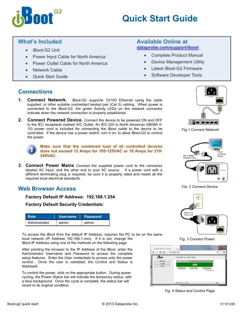
Connections<br />
1. Connect Network. iBoot-G2 supports 10/100 Ethernet using the cable<br />
supplied, or other suitable unshielded twisted pair (Cat 5) cabling. When power is<br />
connected to the iBoot-G2, the green Activity LEDs on the network connector<br />
indicate when the network connection is properly established.<br />
2. Connect Powered Device. Connect the device to be powered ON and OFF<br />
to the IEC receptacle marked A/C Outlet. An IEC-320 to North American (NEMA 5-<br />
15) power cord is included for connecting the iBoot outlet to the device to be<br />
controlled. If the device has a power switch, turn it on, to allow iBoot-G2 to control<br />
the power.<br />
Fig.1 Connect Network<br />
Make sure that the combined load of all controlled devices<br />
does not exceed 12 Amps for 105-125VAC or 10 Amps for 210-<br />
240VAC.<br />
3. Connect Power Mains Connect the supplied power cord to the connector<br />
labeled AC Input, and the other end to your AC source. If a power cord with a<br />
different terminating plug is required, be sure it is properly rated and meets all the<br />
required local electrical standards.<br />
Web Browser Access<br />
Factory Default IP Address: 192.168.1.254<br />
Factory Default Security Credentials:<br />
Fig. 2 Connect Device<br />
Role Username Password<br />
Administrator admin admin<br />
To access the iBoot from the default IP Address, requires the PC to be on the same<br />
local network (IP Address 192.168.1.nnn). If it is not, change the<br />
iBoot IP Address using one of the methods on the following page.<br />
After pointing the browser to the IP Address of the iBoot, enter the<br />
Administrator Username and Password to access the complete<br />
setup features. Enter the User credentials to access only the power<br />
control. Once the user is validated, the Control and Status is<br />
displayed.<br />
To control the power, click on the appropriate button. During power<br />
cycling, the Power Status bar will indicate the temporary status, with<br />
a blue background. Once the cycle is complete, the status bar will<br />
revert to its original condition.<br />
Fig. 3 Connect Power<br />
Fig. 4 Status and Control Page<br />
Iboot-g2 quick start © 2013 <strong>Dataprobe</strong> <strong>Inc</strong>. V110120E
Changing the IP Address<br />
1. Device Management Utility Obtain the Device<br />
Management Utility (DMU) from <strong>Dataprobe</strong>’s website at<br />
dataprobe.com/support/iboot. The DMU provides the easiest<br />
means to find and configure your iBoot-G2 for use. It can<br />
discover all the iBoots on your network, display the current IP<br />
address of each, and allow setting of any valid IP address.<br />
Note: The IP address can only be set within the first two<br />
minutes of powering up the iBoot. The Setup Utility will only<br />
work with iBoots on the same physical subnets as the PC.<br />
The iBoot-G2 Setup Utility can also be used to return an iBoot-<br />
G2 to its Factory Default condition. This can be used to recover<br />
an iBoot-G2 with a lost password. Highlight an iBoot-G2 from<br />
the display and click Factory Defaults. This must also be done<br />
within the first two minutes of powering up the iBoot.<br />
Fig. 5 Device Management Utility<br />
Complete instructions for the DMU are provided with the<br />
download, and in the full iBoot-G2 Manual.<br />
2. Web Page Setup From the home page, click on Setup,<br />
then Network. Enter the new IP Address, Subnet Mask and<br />
Gateway, then click Save. Click the Reboot button (or press the<br />
reset button next to the power outlet LED) to restart the iBoot-<br />
G2 with the new settings.<br />
3. DHCP From the Home page, click on Setup, then Network.<br />
Change the IP Mode from Static to DHCP. Click Save, then<br />
Reboot. The iBoot-G2 will obtain its network settings from the<br />
server. Check the server, or use the Device Management Utility<br />
to obtain the new settings.<br />
Fig. 6 Network Setup Page<br />
Important Safety Instructions<br />
When using this product, basic safety precautions should always be followed to reduce the risk of fire,<br />
electric shock, and injury to persons, including the following:<br />
1. Read and understand all instructions.<br />
2. Follow all warnings and marked on the product.<br />
3. Unplug this product from the wall outlet before cleaning. Do not use liquid<br />
cleaners or aerosol cleaners. Use a damp cloth for cleaning.<br />
4. Do not use this product in an outdoor environment or near water, for<br />
example, near a bath tub, wash bowl, kitchen sink, or laundry tub, in a wet<br />
basement, or near a swimming pool.<br />
5. Do not place this product on an unstable cart, stand, or table. The product<br />
may fall, causing serious damage to the product.<br />
6. Slots and openings in this product and the back or bottom are provided for<br />
ventilation to protect it from overheating; these openings must not be<br />
blocked or covered. The openings should never be blocked by placing the<br />
product on the bed, sofa, rug, or other similar surface. This product should<br />
never be placed near or over a radiator or heat register. This product<br />
should not be placed in a built-in installation unless proper ventilation is<br />
provided.<br />
7. This product should be operated only from the type of power source<br />
indicated on the marking label. If you are not sure of the type of power<br />
supply to your home, consult your dealer or local power company.<br />
8. This product is equipped with a three wire grounding type plug, a plug<br />
having a third (grounding) pin. This plug will only fit into a grounding type<br />
power outlet. This is a safety feature. If you are unable to insert the plug<br />
into the outlet, contact your electrician to replace your obsolete outlet. Do<br />
not defeat the safety purpose of the grounding type plug. Do not use a 3-<br />
to-2 prong adapter at the receptacle; use of this type adapter may result in<br />
risk of electrical shock and/or damage to this product.<br />
9. Do not allow anything to rest on the power cord. Do not locate this product<br />
where the cord will be abused by persons walking on it.<br />
10. Do not overload wall outlets and extension cords as this can result in the<br />
risk of fire or electric shock.<br />
11. Never push objects of any kind into this product through slots as they may<br />
touch dangerous voltage points or short out parts that could result in a risk<br />
of fire or electrical shock. Never spill liquid of any kind on the product.<br />
12. To reduce the risk of electrical shock, do not disassemble this product, but<br />
take it to a qualified serviceman when some service or repair work is<br />
required. Opening or removing covers may expose you to dangerous<br />
voltages or other risks. <strong>Inc</strong>orrect re-assembly can cause electric shock<br />
when the appliance is subsequently used.<br />
13. Unplug this product from the wall outlet and refer servicing to qualified<br />
service personnel under the following conditions:<br />
a) When the power supply cord or plug is damaged or frayed.<br />
b) If liquid has been spilled into the product.<br />
c) If the product has been exposed to rain or water.<br />
d) If the product does not operate normally by following the operating<br />
instructions. Adjust only those controls that are covered by the<br />
operating instructions because improper adjustment of other controls<br />
may result in damage and will often require extensive work by a<br />
qualified technician to restore the product to normal operation.<br />
e) If the product has been dropped or has been damaged.<br />
f) If the product exhibits a distinct change in performance.<br />
14. Avoid using a telephone (other than a cordless type) during an electrical<br />
storm. There may be a remote risk of electric shock from lightning.<br />
15. Do not use the telephone to report a gas leak in the vicinity of the leak.<br />
16. Do not exceed the maximum output rating of the auxiliary power receptacle.
Mounting Options<br />
iBoot-G2+ is suitable for desktop or shelf mounting. A mounting kit for<br />
wall and DIN rail mounting is available. Order part:<br />
1920034 Mounting Kit for iBoot-G2 Series<br />
1920033 Mounting Kit<br />
iBoot G2 Series<br />
Installing the Wall Mounting Kit<br />
DIN Rail Mounting<br />
1. Remove all cables<br />
from the unit<br />
1. Install the Wall<br />
Mounting Kit as<br />
shown.<br />
2. Remove the four<br />
mounting screws<br />
from the underside<br />
of the unit.<br />
2. Install the DIN rail<br />
clips using the four<br />
screws provided.<br />
Do not<br />
disassemble the<br />
unit.<br />
3. Install the wall<br />
mounting ears to<br />
the unit using the<br />
screws removed in<br />
Step 2<br />
3. Ready for DIN rail<br />
mounting.<br />
4. The unit is ready<br />
for wall mounting.<br />
Use M3 or #4<br />
screws (not<br />
included) for<br />
attachment to<br />
suitable surface.
