FlashRunner FR01ENG User's Manual - Ahlers EDV Systeme GmbH
FlashRunner FR01ENG User's Manual - Ahlers EDV Systeme GmbH
FlashRunner FR01ENG User's Manual - Ahlers EDV Systeme GmbH

You also want an ePaper? Increase the reach of your titles
YUMPU automatically turns print PDFs into web optimized ePapers that Google loves.
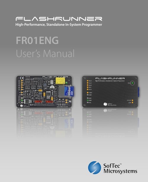
<strong>FlashRunner</strong><br />
<strong>FR01ENG</strong><br />
High-Performance,<br />
Standalone In-System<br />
Programmer<br />
User’s <strong>Manual</strong><br />
Revision 1.0 — May 2008<br />
Copyright © 2008 SMH Technologies<br />
DC10014
We want your feedback!<br />
SMH Technologies is always on the lookout for new ways to improve its<br />
Products and Services. For this reason feedback, comments,<br />
suggestions or criticisms, however small, are always welcome.<br />
Our policy at SMH Technologies is to comply with all applicable worldwide safety and EMC/EMI<br />
regulations. Our products are certified to comply with the European New Approach Directives and the<br />
CE mark is applied on all our products.<br />
This product as shipped from the factory has been verified to meet with requirements FCC as a CLASS<br />
A product.<br />
In a domestic environment, this product may cause radio interference in which case the user may be<br />
required to take adequate prevention measures.<br />
Attaching additional wiring to this product or modifying the product operation from the factory default as<br />
shipped may effect its performance and cause interference with other apparatus in the immediate<br />
vicinity. If such interference is detected, suitable mitigating measures should be taken.<br />
SMH Technologies<br />
E-mail (general information): info@smh-tech.com<br />
E-mail (technical support): support@smh-tech.com<br />
Web: http://www.smh-tech.com<br />
Important<br />
SMH Technologies reserves the right to make improvements to <strong>FlashRunner</strong>, its documentation and software routines, without<br />
notice. Information in this manual is intended to be accurate and reliable. However, SMH Technologies assumes no<br />
responsibility for its use; nor for any infringements of rights of third parties which may result from its use.<br />
SMH TECHNOLOGIES WILL NOT BE LIABLE FOR DAMAGES RESULTING FROM LOSS OF DATA, PROFITS, USE OF<br />
PRODUCTS, OR INCIDENTAL OR CONSEQUENTIAL DAMAGES, EVEN IF ADVISED OF THE POSSIBILITY THEREOF.<br />
Trademarks<br />
SMH Technologies is the licensee of the SofTec Microsystems trademark.<br />
All other product or service names are the property of their respective owners.<br />
Written by Paolo Xausa
<strong>FlashRunner</strong> <strong>FR01ENG</strong> <strong>User's</strong> <strong>Manual</strong><br />
Contents<br />
0 Before Starting 9<br />
0.1 Important Notice to Users 9<br />
0.2 Safety 9<br />
0.3 Getting Technical Support 10<br />
0.4 Additional Documentation 10<br />
1 Overview 11<br />
1.1 What is <strong>FlashRunner</strong> <strong>FR01ENG</strong>? 11<br />
1.1.1 General features 11<br />
1.1.2 Hardware features 11<br />
1.1.3 Software features 12<br />
1.2 Package Checklist 12<br />
1.3 Programming Algorithms and Licenses 14<br />
1.3.1 Installing New Licenses 15<br />
1.4 Upgrading the Firmware 16<br />
2 System Setup 17<br />
2.1 Overview 17<br />
2.2 Software Setup 17<br />
2.3 Hardware Setup 18<br />
2.3.1 Interfacing <strong>FlashRunner</strong> with your Test/Programming<br />
Equipment 18<br />
2.3.2 Connecting <strong>FlashRunner</strong> to the Host PC System 20<br />
2.4 Step-by-Step Tutorial: Sending Commands to <strong>FlashRunner</strong> 20<br />
3 Connectors 27<br />
3.1 Overview 27<br />
3.2 Power Connector 27<br />
3.3 Control Connector 28
Contents<br />
3.4 ISP Connector 30<br />
3.5 ATE Connection Example 33<br />
4 Technical Specifications 35<br />
4.1 Absolute Maximum Ratings 35<br />
4.2 DC Characteristics and Functional Operating Range 36<br />
4.3 AC Characteristics 38<br />
4.4 Physical and Environmental Specifications 39
<strong>FlashRunner</strong> <strong>FR01ENG</strong> <strong>User's</strong> <strong>Manual</strong><br />
Index of Figures<br />
Figure 1.1: <strong>FlashRunner</strong> Top Layer 13<br />
Figure 1.2: <strong>FlashRunner</strong> Bottom Layer (LEDs Side) 14<br />
Figure 1.3: <strong>FlashRunner</strong> Bottom Layer (Connectors Side) 14<br />
Figure 2.1: Typical Programming Connections 19<br />
Figure 2.2: <strong>FlashRunner</strong> Control Panel, Communication Settings 21<br />
Figure 2.3: <strong>FlashRunner</strong> Control Panel, Target Device Configured 22<br />
Figure 2.4: <strong>FlashRunner</strong> Control Panel, Binary File Conversion 23<br />
Figure 2.5: <strong>FlashRunner</strong> Control Panel, File Transfer 24<br />
Figure 2.6: <strong>FlashRunner</strong> Control Panel, Target Device Programmed 25<br />
Figure 3.1: Power Connector 27<br />
Figure 3.2: Control Connector 29<br />
Figure 3.3: ISP Connector 31<br />
Figure 3.4: Example of Connection to an ATE System 33<br />
Figure 4.1: Load Conditions 39<br />
Figure 4.2: Bottom Layer (Connectors Side) Layout 40
<strong>FlashRunner</strong> <strong>FR01ENG</strong> <strong>User's</strong> <strong>Manual</strong><br />
Index of Tables<br />
Table 3.1: Power Connector Signals 28<br />
Table 3.2: Control Connector Signals 30<br />
Table 3.3: ISP Connector Signals 32<br />
Table 4.1: Absolute Maximum Ratings 35<br />
Table 4.2: DC Characteristics and Functional Operating Range 36<br />
Table 4.3: AC Characteristics 38<br />
Table 4.4: Physical and Environmental Specifications 39
0 Before Starting<br />
<strong>FlashRunner</strong> <strong>FR01ENG</strong> <strong>User's</strong> <strong>Manual</strong><br />
0<br />
i<br />
Note: the <strong>FlashRunner</strong> System Software CD-ROM and/or<br />
SofTec Microsystems website (www.softecmicro.com) may<br />
contain an updated version of this user’s manual. Please<br />
check before continuing reading this documentation.<br />
0.1 Important Notice to Users<br />
While every effort has been made to ensure the accuracy of all information in<br />
this document, SMH Technologies assumes no liability to any party for any<br />
loss or damage caused by errors or omissions or by statements of any kind<br />
in this document, its updates, supplements, or special editions, whether such<br />
errors are omissions or statements resulting from negligence, accidents, or<br />
any other cause.<br />
0.2 Safety<br />
<strong>FlashRunner</strong> is a low-voltage device. However, when integrating it inside an<br />
automatic test equipment or when interfacing it with other systems, take all<br />
precautions in order to avoid electrical shocks due to, for example, different<br />
ground references.<br />
Make all connections to the target system before applying power to the<br />
instrument.<br />
To protect <strong>FlashRunner</strong> against electrostatic discharge (ESD), always<br />
connect yourself to ground (e.g. via wrist straps) when handling the<br />
instrument.<br />
Always store <strong>FlashRunner</strong> inside an antistatic bag when not in use.<br />
9
Before Starting<br />
0 0.3 Getting Technical Support<br />
SMH Technologies is continuously working to improve <strong>FlashRunner</strong><br />
firmware and to release programming algorithms for new devices. SMH<br />
Technologies offers a fast and knowledgeable technical support to all of its<br />
customers and is always available to solve specific problems or meet<br />
specific needs.<br />
To get in touch with SMH Technologies, please refer to the contact<br />
information below.<br />
Phone: +39 0434 421111<br />
Fax: +39 0434 639021<br />
Technical Support: support@smh-tech.com<br />
0.4 Additional Documentation<br />
This user’s manual provides information about how to setup <strong>FlashRunner</strong><br />
<strong>FR01ENG</strong> and its hardware characteristics.<br />
For information about <strong>FlashRunner</strong> commands and their syntax, including<br />
specific commands for specific family of microcontrollers, please refer to the<br />
<strong>FlashRunner</strong> Programmer’s <strong>Manual</strong>, included (in PDF format) in the<br />
<strong>FlashRunner</strong> CD-ROM.<br />
10
<strong>FlashRunner</strong> <strong>FR01ENG</strong> <strong>User's</strong> <strong>Manual</strong><br />
1 Overview<br />
1.1 What is <strong>FlashRunner</strong> <strong>FR01ENG</strong>?<br />
1<br />
<strong>FlashRunner</strong> <strong>FR01ENG</strong> is a member of the <strong>FlashRunner</strong> series of a highperformance,<br />
standalone In-System Programmers specific for Flash-based<br />
microcontrollers and serial memories.<br />
<strong>FlashRunner</strong> <strong>FR01ENG</strong> is targeted at production environments and<br />
piggybacks to your programming system or Automatic Test Equipment (ATE)<br />
via header connectors, and can work either in full standalone mode or<br />
controlled by a host system.<br />
1.1.1 General features<br />
• Fastest programming algorithms (as fast as target device’s memory<br />
technology limit), approved by silicon manufacturers;<br />
• Easy ATE integration;<br />
• Standalone operations (projects and code images stored on a memory<br />
card);<br />
• Also controllable by any host system via RS-232;<br />
• Supports most ISP protocols (BDM, JTAG, SPI, I2C, MON, ICC, SCI,<br />
etc.);<br />
• Flexible, fully configurable;<br />
• Compact and robust design for production environments;<br />
• Data integrity guaranteed (every data transfer to/from the host system<br />
or Secure Digital card is CRC tagged).<br />
1.1.2 Hardware features<br />
• 9 to 24V power supply input;<br />
• Five digital I/O lines;<br />
• Two digital I/O or analog output lines;<br />
• Two programmable output voltages (0 to 15V, 0.25A and 0 to 5V, 0.5A);<br />
11
Overview<br />
1<br />
• One analog input line;<br />
• One programmable clock output;<br />
• Secure Digital memory card (up to 2 GB);<br />
• 512 bytes on-board dynamic memory;<br />
• On-board timekeeper and calendar;<br />
• I/O protection;<br />
• Optoisolated inputs for project selection;<br />
• Two optoisolated command inputs (START and STOP);<br />
• Three optoisolated status outputs (FAIL, PASS, BUSY);<br />
• One optoisolated RS-232 channel.<br />
1.1.3 Software features<br />
• Fully autonomous standalone mode thanks to its SD memory card<br />
(FAT16);<br />
• Controllable by any host system through a terminal utility and simple<br />
ASCII protocol;<br />
• Up to 32 hardware-selectable projects (scripts), unlimited softwareselectable<br />
projects;<br />
• Log files;<br />
• Erase, blank check, program, read, verify, oscillator trimming, etc.<br />
1.2 Package Checklist<br />
The <strong>FlashRunner</strong> <strong>FR01ENG</strong> package includes the following items:<br />
• <strong>FlashRunner</strong> <strong>FR01ENG</strong> unit, including an SD card already pre-installed<br />
with the programming algorithm(s) you specified at the time of<br />
purchase;<br />
• <strong>FlashRunner</strong> “System Software” CD-ROM, containing the <strong>FlashRunner</strong><br />
Control Panel utility and the <strong>FlashRunner</strong> Programmer’s <strong>Manual</strong> in PDF<br />
format;<br />
• This user’s manual;<br />
• A registration card.<br />
12
<strong>FlashRunner</strong> <strong>FR01ENG</strong> <strong>User's</strong> <strong>Manual</strong><br />
<strong>FlashRunner</strong> <strong>FR01ENG</strong> is composed of two layers: a bottom layer and a top<br />
layer.<br />
The bottom layer contains all of the <strong>FlashRunner</strong> electronics; the top layer<br />
has the function of protecting the bottom layer and replicating the status<br />
LEDs.<br />
If space is an issue when integrating <strong>FlashRunner</strong> in your<br />
programming/testing system, the top layer can be easily removed.<br />
The following figures show <strong>FlashRunner</strong>’s top and bottom layers.<br />
1<br />
Figure 1.1: <strong>FlashRunner</strong> Top Layer<br />
13
Overview<br />
1<br />
Figure 1.2: <strong>FlashRunner</strong> Bottom Layer (LEDs Side)<br />
Figure 1.3: <strong>FlashRunner</strong> Bottom Layer (Connectors Side)<br />
1.3 Programming Algorithms and Licenses<br />
<strong>FlashRunner</strong> <strong>FR01ENG</strong> includes programming algorithms for several<br />
devices. In order to program a specific device, however, a specific license<br />
file for that device must be purchased.<br />
14
<strong>FlashRunner</strong> <strong>FR01ENG</strong> <strong>User's</strong> <strong>Manual</strong><br />
i<br />
Note: <strong>FlashRunner</strong> <strong>FR01ENG</strong> comes already preinstalled<br />
with the license(s) you specified at the moment of purchase.<br />
You can purchase additional licenses at any future moment.<br />
Programming algorithms and license files are stored in the SD card (see the<br />
<strong>FlashRunner</strong> Programmer’s <strong>Manual</strong> for more information).<br />
1<br />
1.3.1 Installing New Licenses<br />
When you buy an additional license for a specific device, you will get:<br />
• An algorithm file (.alg);<br />
• A license file (.lic);<br />
• A device-specific script example (.frs).<br />
The .alg file contains the actual programming algorithm for the requested<br />
device (and several other devices of the same family).<br />
The .lic file contains an unlocking code that will let you use the programming<br />
algorithm. A license file enables the use of a specific programming algorithm<br />
on a specific <strong>FlashRunner</strong> instrument (licenses are serial number specific).<br />
The script file contains an example of script to use as a starting point for your<br />
specific programming needs (for more information on scripts, see the<br />
<strong>FlashRunner</strong> Programmer’s <strong>Manual</strong>).<br />
To install the new license, do the following:<br />
1. Copy the .alg file into the \ALGOS directory of the SD card (if an<br />
.alg file with the same name already exists, overwrite it);<br />
2. Copy the .lic file into the \LICENSES directory of the SD card.<br />
To copy files on the SD card, use either a standard card reader connected to<br />
a PC or transfer the files using the <strong>FlashRunner</strong> FSSENDFILE command<br />
(for more information on <strong>FlashRunner</strong> commands, see the <strong>FlashRunner</strong><br />
Programmer’s <strong>Manual</strong>).<br />
15
Overview<br />
1<br />
Alternatively, you can use the <strong>FlashRunner</strong> Control Panel utility to install new<br />
programming algorithms and licenses. For more information on the<br />
<strong>FlashRunner</strong> Control Panel please refer to the <strong>FlashRunner</strong> Programmer’s<br />
<strong>Manual</strong>.<br />
1.4 Upgrading the Firmware<br />
The <strong>FlashRunner</strong> firmware can be easily upgraded using the provided<br />
Control Panel utility. For more information, please refer to the <strong>FlashRunner</strong><br />
Programmer’s <strong>Manual</strong>.<br />
16
2 System Setup<br />
<strong>FlashRunner</strong> <strong>FR01ENG</strong> <strong>User's</strong> <strong>Manual</strong><br />
2.1 Overview<br />
i<br />
Note: the example shows how to set up the system for<br />
programming a Freescale MC68HC908QY4 microcontroller.<br />
For how to connect to other target devices, please refer to<br />
the <strong>FlashRunner</strong> Programmer’s <strong>Manual</strong>.<br />
2<br />
This chapter will explain how to set up <strong>FlashRunner</strong> <strong>FR01ENG</strong> for the first<br />
time. Although <strong>FlashRunner</strong> is typically used for standalone operations<br />
(Standalone mode), the examples in this chapter will use the host system to<br />
send commands to <strong>FlashRunner</strong> (Host mode).<br />
When moving <strong>FlashRunner</strong> to the production environment, you can take full<br />
advantage of the instrument’s SD card to make the instrument work without<br />
being controlled by the host system.<br />
For more information about Standalone mode and Host mode, see the<br />
<strong>FlashRunner</strong> Programmer’s <strong>Manual</strong>.<br />
2.2 Software Setup<br />
The <strong>FlashRunner</strong> system software setup installs all of the required<br />
components to your hard drive. These components include:<br />
• The <strong>FlashRunner</strong> Control Panel utility;<br />
• Script examples;<br />
• Documentation in PDF format.<br />
To install the <strong>FlashRunner</strong> system software:<br />
17
System Setup<br />
• Insert the “System Software” CD-ROM into your computer’s CD-ROM<br />
drive;<br />
• A startup window will automatically appear. Choose “Install<br />
Instrument Software” from the main menu. Follow the on-screen<br />
instructions.<br />
2<br />
i<br />
Note: to install the <strong>FlashRunner</strong> system software on<br />
Windows 2000 or Windows XP, you must log in as<br />
Administrator.<br />
2.3 Hardware Setup<br />
To set up <strong>FlashRunner</strong> <strong>FR01ENG</strong>, you must follow the steps below, in the<br />
indicated order:<br />
1. Interface <strong>FlashRunner</strong> with your test/programming equipment;<br />
2. Connect <strong>FlashRunner</strong> to the host PC system;<br />
3. Send <strong>FlashRunner</strong> commands via the <strong>FlashRunner</strong> Control Panel<br />
utility.<br />
2.3.1 Interfacing <strong>FlashRunner</strong> with your Test/Programming Equipment<br />
<strong>FlashRunner</strong> <strong>FR01ENG</strong> typically piggybacks to a carrier board (designed by<br />
you) that interfaces <strong>FlashRunner</strong> to your test/programming equipment and to<br />
your target board. The carrier board must include three female header<br />
connectors that accept <strong>FlashRunner</strong>’s “ISP”, “CONTROL” and “POWER”<br />
connectors. The carrier board:<br />
• Supplies power to <strong>FlashRunner</strong>. <strong>FlashRunner</strong> accepts any DC voltage<br />
between 9 V and 24 V;<br />
• Routes all of the required ISP and power signals from <strong>FlashRunner</strong> to<br />
the target board;<br />
• Routes the RS-232 signals from <strong>FlashRunner</strong> “CONTROL” connector to<br />
a RS-232 connector (for communication with a host PC).<br />
18
<strong>FlashRunner</strong> <strong>FR01ENG</strong> <strong>User's</strong> <strong>Manual</strong><br />
• Routes control signals (START, STOP, BUSY, PASS, FAIL and script<br />
selection lines) to your test/programming equipment (only necessary for<br />
standalone operations).<br />
Connections between the carrier board and the target board typically consist<br />
of flat cables that plug into the ISP connector on the target board(s) or single<br />
wires that connect to the single nails of your bed-of-nails fixture.<br />
The figure below illustrates typical programming connections.<br />
2<br />
Carrier Board<br />
“CONTROL” Connector<br />
“POWER” Connector<br />
“ISP” Connector<br />
To Target Board<br />
Figure 2.1: Typical Programming Connections<br />
The specific ISP signals that must be routed from <strong>FlashRunner</strong> <strong>FR01ENG</strong> to<br />
your target board depend on the specific target device. Typical connections<br />
for all the device families supported by <strong>FlashRunner</strong> are shown in the<br />
<strong>FlashRunner</strong> Programmer’s <strong>Manual</strong>.<br />
19
System Setup<br />
2.3.2 Connecting <strong>FlashRunner</strong> to the Host PC System<br />
To connect <strong>FlashRunner</strong> <strong>FR01ENG</strong> to a host PC, you must provide a RS-<br />
232 connector in your carrier board first, routing the appropriate signals from<br />
<strong>FlashRunner</strong>’s “CONTROL” connector to the RS-232 connector.<br />
2<br />
2.4 Step-by-Step Tutorial: Sending Commands to<br />
<strong>FlashRunner</strong><br />
After setting up the hardware, you are ready to send commands to the<br />
instrument. The following steps will guide you through the process of<br />
launching your first <strong>FlashRunner</strong> commands using the provided <strong>FlashRunner</strong><br />
Control Panel utility. For detailed information about the <strong>FlashRunner</strong> Control<br />
Panel utility, see the <strong>FlashRunner</strong> Programmer’s <strong>Manual</strong>.<br />
i<br />
Note: the following steps show how to program a Freescale<br />
MC68HC908QY4 microcontroller, and the details are<br />
therefore specific for that microcontroller. However, the<br />
procedures shown are general and will allow you get a feel<br />
of how <strong>FlashRunner</strong> works.<br />
1. Launch the <strong>FlashRunner</strong> Control Panel utility. Select Start > Programs<br />
> SofTec Microsystems > <strong>FlashRunner</strong> > Control Panel. The Control<br />
Panel utility will open.<br />
2. To establish a connection with <strong>FlashRunner</strong>, on the “Communication<br />
Settings” section, select “<strong>FlashRunner</strong> serial version” and specify<br />
the COM port you are using and the baud rate (by default, <strong>FlashRunner</strong><br />
communicates at 115200 bps).<br />
20
<strong>FlashRunner</strong> <strong>FR01ENG</strong> <strong>User's</strong> <strong>Manual</strong><br />
2<br />
Figure 2.2: <strong>FlashRunner</strong> Control Panel, Communication Settings<br />
3. Click the “Connect” button. On the “Communication History”<br />
section, note the commands that have been sent and received. In this<br />
case, the SPING command is automatically sent to <strong>FlashRunner</strong>,<br />
which replies with the PONG> string.<br />
4. In the edit box below the communication history, type the following<br />
commands (each followed by Return):<br />
TCSETDEV FREESCALE MC68HC908QY4 HC08<br />
TCSETPAR FOSC 16000000<br />
TCSETPAR FDIV 4<br />
TCSETPAR VDD 5000<br />
These commands set, respectively, the target microcontroller, the<br />
oscillator frequency, the internal divisor and the VDD voltage. In this<br />
example, we used a 16 MHz oscillator, the internal divisor for<br />
MC68HC908QY4 devices is fixed to 4, and the VDD is 5 V.<br />
21
System Setup<br />
<strong>FlashRunner</strong> will respond to each command with the > string,<br />
indicating that the command has been successfully executed. After<br />
sending these commands, the Control Panel will look like the figure<br />
below.<br />
2<br />
Figure 2.3: <strong>FlashRunner</strong> Control Panel, Target Device Configured<br />
5. When working with Freescale HC08 devices, <strong>FlashRunner</strong> requires you<br />
to specify the power up and power down times, in milliseconds. Send<br />
the following two commands:<br />
TCSETPAR PWDOWN 10<br />
TCSETPAR PWUP 10<br />
6. After specifying the target device settings, we are ready to transfer to<br />
<strong>FlashRunner</strong> the binary image to be programmed into the target device.<br />
<strong>FlashRunner</strong> accepts only image files in a .frb (<strong>FlashRunner</strong> Binary)<br />
format. To convert your binary, Intel-Hex or S19 image file to the<br />
22
<strong>FlashRunner</strong> <strong>FR01ENG</strong> <strong>User's</strong> <strong>Manual</strong><br />
<strong>FlashRunner</strong> format, click the “Create <strong>FlashRunner</strong> Binary Format”<br />
button. The following dialog box will appear.<br />
2<br />
Figure 2.4: <strong>FlashRunner</strong> Control Panel, Binary File Conversion<br />
In the “Input” section, specify the source file to be converted, its<br />
format, and the address from which the file conversion will start (offset).<br />
In the “Output” section, specify the output filename and the value used<br />
to fill unused locations.<br />
Click the “OK” button. The <strong>FlashRunner</strong> Binary file will be created in<br />
the local \BINARIES folder.<br />
7. To transfer the created image to <strong>FlashRunner</strong>, send the following<br />
command:<br />
TPSENDFILE YMODEM DEMO.FRB<br />
In this example, the image file is called DEMO.FRB. The following<br />
dialog box will appear.<br />
23
System Setup<br />
2<br />
Figure 2.5: <strong>FlashRunner</strong> Control Panel, File Transfer<br />
Click the “...” button to browse for the image file to be sent, then click<br />
“Start” to begin the transfer. The file will be saved to the <strong>FlashRunner</strong><br />
SD card, in the \BINARIES folder.<br />
8. We are now ready to start the actual programming part. Send the<br />
following commands:<br />
TPSETSRC FILE DEMO.FRB<br />
TPSTART<br />
TPCMD SETPWD CONST $FF $FF $FF $FF $FF $FF $FF $FF<br />
TPCMD MASSERASE F<br />
TPCMD BLANKCHECK F $EE00 4608<br />
TPCMD PROGRAM F $EE00 $EE00 4608<br />
TPCMD VERIFY F S $EE00 $EE00 4608<br />
TPEND<br />
The data to be programmed is taken from the image file starting at<br />
$EE00 (offset from the beginning of the file), is programmed to the<br />
target microcontroller starting from the location $EE00 and is 4608<br />
bytes long.<br />
The TPSETSRC command specifies the source file for the TPCMD<br />
PROGRAM e TPCMD VERIFY commands that come next. All the actual<br />
programming operations are sent between a TPSTART and TPEND<br />
command. The TPCMD SETPWD command sets the security bytes<br />
needed to perform subsequent operations.<br />
After sending these commands, the Control Panel will look like the<br />
figure below.<br />
24
<strong>FlashRunner</strong> <strong>FR01ENG</strong> <strong>User's</strong> <strong>Manual</strong><br />
2<br />
Figure 2.6: <strong>FlashRunner</strong> Control Panel, Target Device Programmed<br />
9. We are now done with programming the target device. Click the<br />
“Disconnect” button to free the serial port resource.<br />
For detailed information on all of the <strong>FlashRunner</strong> commands and their<br />
syntax, including specific commands for specific family of microcontrollers,<br />
please refer to the <strong>FlashRunner</strong> Programmer’s <strong>Manual</strong>, included (in PDF<br />
format) in the <strong>FlashRunner</strong> CD-ROM.<br />
Programming can be automated by creating “scripts”. Scripts are text files,<br />
stored in the SD card, which contain a sequence of <strong>FlashRunner</strong> commands.<br />
See the <strong>FlashRunner</strong> Programmer’s <strong>Manual</strong> for more information about<br />
scripts.<br />
25
<strong>FlashRunner</strong> <strong>FR01ENG</strong> <strong>User's</strong> <strong>Manual</strong><br />
3 Connectors<br />
3.1 Overview<br />
<strong>FlashRunner</strong> connects to your programming/testing system through three<br />
header connectors: one groups ISP signals, one groups control signals, and<br />
one groups power signals.<br />
3.2 Power Connector<br />
3<br />
The “POWER” connector is used to power <strong>FlashRunner</strong>. This connector also<br />
includes reserved expansion lines, which must not be connected.<br />
RESERVED<br />
RESERVED<br />
RESERVED<br />
RESERVED<br />
RESERVED<br />
RESERVED<br />
RESERVED<br />
POWER<br />
POWER<br />
POWER<br />
1 2 RESERVED<br />
3 4 RESERVED<br />
5 6 RESERVED<br />
7 8 RESERVED<br />
9 10 RESERVED<br />
11 12 5V<br />
13 14 RESERVED<br />
15 16 GND<br />
17 18 GND<br />
19 20 GND<br />
“POWER”<br />
Connector<br />
Figure 3.1: Power Connector<br />
27
Connectors<br />
Pin # Signal Name Description<br />
Table 3.1: Power Connector Signals<br />
3<br />
1 RESERVED Internal line for future expansion. Do not connect.<br />
2 RESERVED Internal line for future expansion. Do not connect.<br />
3 RESERVED Internal line for future expansion. Do not connect.<br />
4 RESERVED Internal line for future expansion. Do not connect.<br />
5 RESERVED Internal line for future expansion. Do not connect.<br />
6 RESERVED Internal line for future expansion. Do not connect.<br />
7 RESERVED Internal line for future expansion. Do not connect.<br />
8 RESERVED Internal line for future expansion. Do not connect.<br />
9 RESERVED Internal line for future expansion. Do not connect.<br />
10 RESERVED Internal line for future expansion. Do not connect.<br />
11 RESERVED Internal line for future expansion. Do not connect.<br />
12 5V User power supply (output, 5V)<br />
13 RESERVED Internal line for future expansion. Do not connect.<br />
14 RESERVED Internal line for future expansion. Do not connect.<br />
15 POWER <strong>FlashRunner</strong> power supply (input, 9-24V)<br />
16 GND Ground<br />
17 POWER <strong>FlashRunner</strong> power supply (input, 9-24V)<br />
18 GND Ground<br />
19 POWER <strong>FlashRunner</strong> power supply (input, 9-24V)<br />
20 GND Ground<br />
3.3 Control Connector<br />
The “CONTROL” connector is used by <strong>FlashRunner</strong> to communicate with<br />
the host system and for integration with an automatic programming/testing<br />
equipment.<br />
i<br />
Note: all control signals are optoisolated. You must power<br />
the optoisolation circuitry through the OPTO_5V and<br />
OPTO_GND lines.<br />
If your system doesn’t require optoisolation, just connect the<br />
OPTO_5V and OPTO_GND lines to the 5V and GND lines<br />
(respectively) of the “POWER” connector.<br />
28
<strong>FlashRunner</strong> <strong>FR01ENG</strong> <strong>User's</strong> <strong>Manual</strong><br />
TX_RS232<br />
1 2 RX_RS232<br />
TX<br />
3 4 RX<br />
STOP<br />
5 6 OPTO_5V<br />
START<br />
7 8 BUSY<br />
PASS<br />
9 10 FAIL<br />
SEL0<br />
SEL2<br />
SEL4<br />
11 12 SEL1<br />
13 14 SEL3<br />
15 16 OPTO_GND<br />
“CONTROL”<br />
Connector<br />
3<br />
Figure 3.2: Control Connector<br />
29
Connectors<br />
Pin # Signal Name Description<br />
Table 3.2: Control Connector Signals<br />
3<br />
1 TX_RS232 TX (output, optoisolated, RS-232 levels)<br />
2 RX_RS232 RX (input, optoisolated, RS-232 levels)<br />
3 TX TX (output , open-drain, optoisolated, 0-5V levels)<br />
4 RX RX (input, optoisolated, 0-5V levels)<br />
5 STOP STOP (input , optoisolated, active low)<br />
6 OPTO_5V Optoisolation power supply (input, 5V). If your system doesn’t require optoisolation,<br />
connect this line to the “5V” lines of the “POWER” connector.<br />
7 START START (input , optoisolated, active low)<br />
8 BUSY BUSY (output, open-drain, optoisolated, active low)<br />
9 PASS PASS (output, open-drain, optoisolated, active low)<br />
10 FAIL FAIL (output, open-drain, optoisolated, active low)<br />
11 SEL0 Script selection 0 (input, optoisolated)<br />
12 SEL1 Script selection 1 (input, optoisolated)<br />
13 SEL2 Script selection 2 (input, optoisolated)<br />
14 SEL3 Script selection 3 (input, optoisolated)<br />
15 SEL4 Script selection 4 (input, optoisolated)<br />
16 OPTO_GND Optoisolation ground. If your system doesn’t require optoisolation, connect this line to the<br />
“GND” lines of the “POWER” connector.<br />
3.4 ISP Connector<br />
The “ISP” connector has all of the signals needed to program the target<br />
device. This connector has several input/output lines, both digital and<br />
analog, which are automatically configured by <strong>FlashRunner</strong> depending on<br />
the specific target device to be programmed (see the <strong>FlashRunner</strong><br />
Programmer’s <strong>Manual</strong> to learn how to connect these lines to your specific<br />
target device).<br />
!<br />
Note: ISP signals are not optoisolated.<br />
30
<strong>FlashRunner</strong> <strong>FR01ENG</strong> <strong>User's</strong> <strong>Manual</strong><br />
DIO0/AO0<br />
1 2 GND<br />
GND<br />
3 4 GND<br />
DIO1/AO1<br />
5 6 VPROG0<br />
GND<br />
7 8 VPROG0<br />
DIO2<br />
9 10 GND<br />
GND<br />
DIO3<br />
GND<br />
DIO4<br />
11 12 VPROG0<br />
13 14 VPROG0<br />
15 16 GND<br />
17 18 VPROG1<br />
3<br />
GND<br />
19 20 VPROG1<br />
DIO5<br />
21 22 GND<br />
GND<br />
23 24 GND<br />
DIO6<br />
25 26 AIN0<br />
GND<br />
27 28 GND<br />
CLKOUT<br />
29 30 GND<br />
GND<br />
31 32 GND<br />
GND<br />
33 34 GND<br />
GND<br />
35 36 GND<br />
“ISP”<br />
Connector<br />
Figure 3.3: ISP Connector<br />
31
Connectors<br />
Pin # Signal Name Description<br />
Table 3.3: ISP Connector Signals<br />
3<br />
1 DIO0/AO0 Digital input/output 0 or analog output 0<br />
2 GND Ground<br />
3 GND Ground<br />
4 GND Ground<br />
5 DIO1/AO1 Digital input/output 1 or analog output 1<br />
6 VPROG0 Programmable voltage 0 (max 5.5V, 500mA)<br />
7 GND Ground<br />
8 VPROG0 Programmable voltage 0 (max 5.5V, 500mA)<br />
9 DIO2 Digital input/output 2<br />
10 GND Ground<br />
11 GND Ground<br />
12 VPROG0 Programmable voltage 0 (max 5.5V, 500mA)<br />
13 DIO3 Digital input/output 3<br />
14 VPROG0 Programmable voltage 0 (max 5.5V, 500mA)<br />
15 GND Ground<br />
16 GND Ground<br />
17 DIO4 Digital input/output 4<br />
18 VPROG1 Programmable voltage 1 (max 14.5V, 250mA)<br />
19 GND Ground<br />
20 VPROG1 Programmable voltage 1 (max 14.5V, 250mA)<br />
21 DIO5 Digital input/output 5<br />
22 GND Ground<br />
23 GND Ground<br />
24 GND Ground<br />
25 DIO6 Digital input/output 6<br />
26 AIN0 Analog input 0 (max 28.5V)<br />
27 GND Ground<br />
28 GND Ground<br />
29 CLKOUT Clock output<br />
30 GND Ground<br />
31 GND Ground<br />
32 GND Ground<br />
33 GND Ground<br />
34 GND Ground<br />
35 GND Ground<br />
36 GND Ground<br />
32
<strong>FlashRunner</strong> <strong>FR01ENG</strong> <strong>User's</strong> <strong>Manual</strong><br />
3.5 ATE Connection Example<br />
The figure below shows an example of connection between <strong>FlashRunner</strong><br />
and an ATE system. In this example, the target board is automatically<br />
powered by <strong>FlashRunner</strong> through the VPROG0 line.<br />
+<br />
-<br />
9-24V<br />
POWER<br />
GND<br />
3<br />
To <strong>FlashRunner</strong><br />
“POWER” connector<br />
To <strong>FlashRunner</strong><br />
“ISP” connector<br />
…<br />
…<br />
To <strong>FlashRunner</strong><br />
“CONTROL” connector<br />
(SEL[4..0], START, STOP,<br />
BUSY, PASS, FAIL)<br />
VATE<br />
VPROG0<br />
TGT ISP<br />
ATE CTRL<br />
+<br />
-<br />
GND<br />
ATE POWER<br />
GND<br />
TGT POWER<br />
TARGET BOARD<br />
ATE<br />
Figure 3.4: Example of Connection to an ATE System<br />
33
Connectors<br />
i<br />
Note: all control signals are optoisolated. You must power<br />
the optoisolation circuitry through the OPTO_5V and<br />
OPTO_GND lines of the “CONTROL” connector.<br />
If your system doesn’t require optoisolation, just connect the<br />
OPTO_5V and OPTO_GND lines of the “CONTROL”<br />
connector to the 5V and GND lines (respectively) of the<br />
“POWER” connector.<br />
3<br />
34
<strong>FlashRunner</strong> <strong>FR01ENG</strong> <strong>User's</strong> <strong>Manual</strong><br />
4 Technical Specifications<br />
4.1 Absolute Maximum Ratings<br />
Table 4.1: Absolute Maximum Ratings<br />
Parameter<br />
Value<br />
“CONTROL” Connector<br />
Maximum input voltage on lines START, STOP, SEL[4..0], RX -2V to +9V<br />
Maximum input voltage on line RX_RS232 -25V to +25V<br />
Maximum input voltage on line OPTO_5V (reference OPTO_GND)<br />
6V<br />
Maximum current on lines BUSY, PASS,FAIL,TX<br />
-50mA to 1.5mA<br />
Maximum current on line TX_RS232<br />
±60mA<br />
“ISP” Connector<br />
Maximum input voltage on lines DIO/AO[1..0], DIO[6..2], CLKOUT -1V to +7V<br />
Maximum input voltage on line AIN0 -12V to +40V<br />
Maximum current on lines DIO/AO[1..0], DIO[6..2], CLKOUT<br />
±50mA<br />
Maximum current on line VPROG0<br />
500mA<br />
Maximum current on line VPROG1<br />
250mA<br />
4<br />
“POWER” Connector<br />
Maximum supply voltage on line POWER (reference GND) -20V to +30V<br />
Maximum current on line 5V<br />
150mA<br />
35
Technical Specifications<br />
4.2 DC Characteristics and Functional Operating<br />
Range<br />
Table 4.2: DC Characteristics and Functional Operating Range<br />
Parameter<br />
Condition<br />
Value<br />
Min Typ Max<br />
4<br />
“CONTROL” Connector<br />
V IL (input low voltage) on lines START, STOP,<br />
SEL[4..0], RX<br />
V IH (input high voltage) on lines START, STOP,<br />
SEL[4..0], RX<br />
The driver must be able to<br />
provide at least 5mA<br />
0V - 2V<br />
3V - 5V<br />
V IL (input low voltage) on line RX_RS232 - - 1.2V<br />
V IH (input high voltage) on line RX_RS232 2.4V - -<br />
V OL (output low voltage) on lines BUSY, FAIL,<br />
PASS, TX<br />
V OH (output high voltage) on lines BUSY, FAIL,<br />
PASS, TX<br />
I OL = 4.5mA - - 450mV<br />
4.5V - 5V<br />
V OL (output low voltage) on line TX_RS232 R LOAD = 3KΩ - - -5V<br />
V OH (output high voltage) on line TX_RS232 R LOAD = 3KΩ +5V - -<br />
OPTO_5V line power consumption - 100mA -<br />
“ISP” Connector<br />
V IL (input low voltage) on lines DIO[6..2], DIO[1..0] Configured as digital lines - - 0.3V PROG0<br />
V IH (input high voltage) on lines DIO[6..2], DIO[1..0] Configured as digital lines 0.7V PROG0 - V PROG0<br />
V OL (output low voltage) on lines DIO[6..2],<br />
DIO[1..0], CLKOUT<br />
V OH (output high voltage) on lines DIO[6..2],<br />
DIO[1..0], CLKOUT<br />
V OL (output low voltage) on lines DIO[6..2],<br />
DIO[1..0], CLKOUT<br />
V OH (output high voltage) on lines DIO[6..2],<br />
DIO[1..0], CLKOUT<br />
I OH current (source) on lines DIO[6..2], DIO[1..0]<br />
Configured as digital lines,<br />
V PROG0 = 3V, I OL = 12mA<br />
Configured as digital lines,<br />
V PROG0 = 3V, I OH = 12mA<br />
Configured as digital lines,<br />
V PROG0 = 5.5V, I OL = 24mA<br />
Configured as digital lines,<br />
V PROG0 = 5.5V, I OH = 24mA<br />
Configured as input with<br />
active pull-ups<br />
- - 0.36V<br />
2.56V - -<br />
- - 0.36V<br />
4.86V - -<br />
- 3.4mA -<br />
DIO/AO[1..0] voltage Configured as analog output 3V - 14.5V<br />
DIO/AO[1..0] IO current (sink and source) Configured as analog output - - ±40mA<br />
I OH current (source) on lines DIO/AO[1..0]<br />
Configured as analog lines<br />
with active pull-ups<br />
- 5.5mA -<br />
I L (input leakage current) on line AIN0 V AIN0 = 25V - - 4.3mA<br />
AIN0 line input voltage 0V - 28.5V<br />
VPROG0 line output voltage 1.6V - 5.5V<br />
VPROG0 current (source) - - 500mA<br />
VPROG1 line output voltage 3V - 14.5V<br />
36
<strong>FlashRunner</strong> <strong>FR01ENG</strong> <strong>User's</strong> <strong>Manual</strong><br />
Parameter<br />
Condition<br />
Value<br />
Min Typ Max<br />
VPROG1 current (source) - - 250mA<br />
“POWER” Connector<br />
Supply voltage 9V - 24V<br />
Power consumption - - 1.5A<br />
5V line output current - - 100mA<br />
5V line output voltage 4.75V 5V 5.25V<br />
4<br />
37
Technical Specifications<br />
4.3 AC Characteristics<br />
Table 4.3: AC Characteristics<br />
4<br />
Parameter<br />
t RISE on lines DIO[6..2],<br />
DIO[1..0], CLKOUT when<br />
configured as digital output<br />
push-pull<br />
t FALL on lines DIO[6..2],<br />
DIO[1..0], CLKOUT when<br />
configured as digital output<br />
push-pull<br />
t RISE on lines DIO/AO[1..0]<br />
configured as analog output<br />
t FALL on lines DIO/AO[1..0]<br />
configured as analog output<br />
t RISE on line VPROG0<br />
t FALL on line VPROG0<br />
t RISE on line VPROG1<br />
t FALL on line VPROG1<br />
Condition<br />
Value<br />
Min Typ Max<br />
V PROG0 = 1.8V - 40ns -<br />
V PROG0 = 3.3V<br />
Load: 470Ω//100pF<br />
(see figure 4.1a)<br />
- 30ns -<br />
V PROG0 = 5V<br />
- 25ns -<br />
V PROG0 = 1.8V - 35ns -<br />
V PROG0 = 3.3V<br />
Load: 470Ω//100pF<br />
(see figure 4.1a)<br />
- 25ns -<br />
V PROG0 = 5V<br />
- 25ns -<br />
V PROG1 = 3V - 7µs -<br />
V PROG1 = 12V<br />
Load: 4.7KΩ//100pF<br />
(see figure 4.1a)<br />
- 11µs -<br />
V PROG1 = 14.5V<br />
- 12µs -<br />
V PROG1 = 3V - 8µs -<br />
V PROG1 = 12V Load: 100pF (see figure 4.1b)<br />
- 20µs -<br />
V PROG1 = 14.5V<br />
- 30µs -<br />
V PROG0 = 0-1.8V Load: 15Ω//10mF (see figure 4.1a) - 10ms -<br />
V PROG0 = 0-3.3V Load: 22Ω//10mF (see figure 4.1a) - 15ms -<br />
V PROG0 = 0-5.5V Load: 22Ω//10mF (see figure 4.1a) - 20ms -<br />
V PROG0 = 1.8-0V - 300ms -<br />
V PROG0 = 3.3-0V Load: 10mF (see figure 41b)<br />
- 350ms -<br />
V PROG0 = 5.5-0V<br />
- 350ms -<br />
V PROG1 = 0-3V Load: 10Ω//1mF (see figure 4.1a) - 1.3ms -<br />
V PROG1 = 0-5V Load: 47Ω//1mF (see figure 4.1a) - 1.8ms -<br />
V PROG1 = 0-14.5V Load: 94Ω//1mF (see figure 4.1a) - 13ms -<br />
V PROG1 = 3-0V - 18ms -<br />
V PROG1 = 5-0V Load: 1mF (see figure 4.1b)<br />
- 30ms -<br />
V PROG1 = 14.5-0V<br />
- 45ms -<br />
CLKOUT frequency 0MHz - 50MHz<br />
38
<strong>FlashRunner</strong> <strong>FR01ENG</strong> <strong>User's</strong> <strong>Manual</strong><br />
a<br />
b<br />
<strong>FlashRunner</strong><br />
<strong>FlashRunner</strong><br />
R<br />
C<br />
C<br />
Figure 4.1: Load Conditions<br />
4.4 Physical and Environmental Specifications<br />
Table 4.4: Physical and Environmental Specifications<br />
Parameter<br />
Value<br />
Dimensions (with top panel)<br />
130 x 74 x 27 mm<br />
Dimensions (without top panel)<br />
130 x 74 x 22 mm<br />
“ISP” connector type<br />
36-pin, 2.54mm-pitch, dual-row header (male)<br />
“CONTROL” connector type<br />
16-pin, 2.54mm-pitch, dual-row header (male)<br />
“POWER” connector type<br />
20-pin, 2.54mm-pitch, dual-row header (male)<br />
Operating temperature<br />
0-50°C<br />
Operating humidity<br />
90% max (without condensation)<br />
Storage temperature<br />
0-70°C<br />
Storage humidity<br />
90% max (without condensation)<br />
4<br />
39
Technical Specifications<br />
4<br />
Figure 4.2: Bottom Layer (Connectors Side) Layout<br />
40