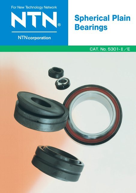
Spherical Plain Bearings - NTN
Spherical Plain Bearings - NTN
Spherical Plain Bearings - NTN
Create successful ePaper yourself
Turn your PDF publications into a flip-book with our unique Google optimized e-Paper software.
For New Technology Network<br />
R<br />
<strong>Spherical</strong> <strong>Plain</strong><br />
<strong>Bearings</strong><br />
corporation<br />
@
Warranty<br />
<strong>NTN</strong> warrants, to the original purchaser only, that the delivered product which is the subject of this sale (a)<br />
will conform to drawings and specifications mutually established in writing as applicable to the contract, and (b)<br />
be free from defects in material or fabrication. The duration of this warranty is one year from date of delivery.<br />
If the buyer discovers within this period a failure of the product to conform to drawings or specifications, or a<br />
defect in material or fabrication, it must promptly notify <strong>NTN</strong> in writing. In no event shall such notification be<br />
received by <strong>NTN</strong> later than 13 months from the date of delivery. Within a reasonable time after such<br />
notification, <strong>NTN</strong> will, at its option, (a) correct any failure of the product to conform to drawings, specifications<br />
or any defect in material or workmanship, with either replacement or repair of the product, or (b) refund, in part<br />
or in whole, the purchase price. Such replacement and repair, excluding charges for labor, is at <strong>NTN</strong>'s<br />
expense. All warranty service will be performed at service centers designated by <strong>NTN</strong>. These remedies are<br />
the purchaser's exclusive remedies for breach of warranty.<br />
<strong>NTN</strong> does not warrant (a) any product, components or parts not manufactured by <strong>NTN</strong>, (b) defects caused<br />
by failure to provide a suitable installation environment for the product, (c) damage caused by use of the<br />
product for purposes other than those for which it was designed, (d) damage caused by disasters such as fire,<br />
flood, wind, and lightning, (e) damage caused by unauthorized attachments or modification, (f) damage during<br />
shipment, or (g) any other abuse or misuse by the purchaser.<br />
THE FOREGOING WARRANTIES ARE IN LIEU OF ALL OTHER WARRANTIES, EXPRESS OR IMPLIED,<br />
INCLUDING BUT NOT LIMITED TO THE IMPLIED WARRANTIES OF MERCHANTABILITY AND FITNESS<br />
FOR A PARTICULAR PURPOSE.<br />
In no case shall <strong>NTN</strong> be liable for any special, incidental, or consequential damages based upon breach of<br />
warranty, breach of contract, negligence, strict tort, or any other legal theory,and in no case shall total liability<br />
of <strong>NTN</strong> exceed the purchase price of the part upon which such liability is based. Such damages include, but<br />
are not limited to, loss of profits, loss of savings or revenue, loss of use of the product or any associated<br />
equipment, cost of capital, cost of any substitute equipment, facilities or services, downtime, the claims of third<br />
parties including customers, and injury to property. Some states do not allow limits on warranties, or on<br />
remedies for breach in certain transactions. In such states, the limits in this paragraph and in paragraph (2)<br />
shall apply to the extent allowable under case law and statutes in such states.<br />
Any action for breach of warranty or any other legal theory must be commenced within 15 months following<br />
delivery of the goods.<br />
Unless modified in a writing signed by both parties, this agreement is understood to be the complete and<br />
exclusive agreement between the parties, superceding all prior agreements, oral or written, and all other<br />
communications between the parties relating to the subject matter of this agreement. No employee of <strong>NTN</strong> or<br />
any other party is authorized to make any warranty in addition to those made in this agreement.<br />
This agreement allocates the risks of product failure between <strong>NTN</strong> and the purchaser. This allocation is<br />
recognized by both parties and is reflected in the price of the goods. The purchaser acknowledges that it has<br />
read this agreement, understands it, and is bound by its terms.<br />
© <strong>NTN</strong> Corporation. 2000<br />
Although care has been taken to assure the accuracy of the data compiled in this catalog, <strong>NTN</strong> does not<br />
assume any liability to any company or person for errors or omissions.
<strong>NTN</strong> SPHERICAL PLAIN<br />
BEARINGS
<strong>NTN</strong> SPHERICAL PLAIN BEARINGS<br />
CONTENTS<br />
TECHNICAL DATA<br />
1. Types of <strong>Spherical</strong> <strong>Plain</strong> <strong>Bearings</strong> ⋯⋯⋯⋯⋯⋯⋯⋯⋯⋯⋯⋯⋯3<br />
2. Tolerances of <strong>Spherical</strong> <strong>Plain</strong> <strong>Bearings</strong> ⋯⋯⋯⋯⋯⋯⋯⋯⋯⋯⋯4<br />
3. Loads Acting on <strong>Spherical</strong> <strong>Plain</strong> <strong>Bearings</strong> ⋯⋯⋯⋯⋯⋯⋯⋯⋯⋯6<br />
4. Selection of <strong>Spherical</strong> <strong>Plain</strong> <strong>Bearings</strong> ⋯⋯⋯⋯⋯⋯⋯⋯⋯⋯⋯⋯7<br />
5. Life of <strong>Spherical</strong> <strong>Plain</strong> <strong>Bearings</strong>⋯⋯⋯⋯⋯⋯⋯⋯⋯⋯⋯⋯⋯⋯⋯9<br />
6. Recommended Fit and Internal Clearance ⋯⋯⋯⋯⋯⋯⋯⋯⋯11<br />
7. Cautions to Installation ⋯⋯⋯⋯⋯⋯⋯⋯⋯⋯⋯⋯⋯⋯⋯⋯⋯⋯12<br />
BEARING TABLES<br />
<strong>Spherical</strong> <strong>Plain</strong> <strong>Bearings</strong><br />
Self-lubricating type<br />
Series SAR1/SAR1SS ⋯⋯⋯⋯⋯⋯⋯⋯⋯⋯⋯⋯⋯⋯⋯⋯⋯13<br />
Series SAR4 ⋯⋯⋯⋯⋯⋯⋯⋯⋯⋯⋯⋯⋯⋯⋯⋯⋯⋯⋯⋯⋯⋯14<br />
Series SAR2 (Inch size) ⋯⋯⋯⋯⋯⋯⋯⋯⋯⋯⋯⋯⋯⋯⋯⋯⋯15<br />
Lubricating type<br />
Series SA1/SA1SS ⋯⋯⋯⋯⋯⋯⋯⋯⋯⋯⋯⋯⋯⋯⋯⋯⋯⋯16<br />
Series SA4 ⋯⋯⋯⋯⋯⋯⋯⋯⋯⋯⋯⋯⋯⋯⋯⋯⋯⋯⋯⋯⋯⋯⋯18<br />
Series SA2 (Inch size) ⋯⋯⋯⋯⋯⋯⋯⋯⋯⋯⋯⋯⋯⋯⋯⋯⋯⋯20<br />
Thrust <strong>Spherical</strong> <strong>Plain</strong> <strong>Bearings</strong><br />
Lubricating type<br />
Series SAT ⋯⋯⋯⋯⋯⋯⋯⋯⋯⋯⋯⋯⋯⋯⋯⋯⋯⋯⋯⋯⋯⋯⋯22<br />
Self-Iubrication type<br />
Lubrication type<br />
Lubrication type thrust<br />
bushing<br />
2
<strong>NTN</strong> SPHERICAL PLAIN BEARINGS<br />
<strong>Spherical</strong> plain bearings are used in equipment that<br />
undergo articulated movement, involving oscillating or<br />
aligning motions.<br />
<strong>NTN</strong> spherical plain bearings are classified broadly into<br />
the self-lubricating type with a solid PTFE based liner<br />
and the lubrication type in which contact between the<br />
inner and outer rings is metal-to-metal.<br />
1. Types of <strong>Spherical</strong> <strong>Plain</strong> <strong>Bearings</strong><br />
1.1 Self-lubricating type spherical plain<br />
bearings<br />
1.2 Lubrication type spherical plain<br />
bearings<br />
Self-lubricating spherical plain bearings are primarily<br />
intended for situations where a long life, free from maintenance<br />
and lubrication requirements, is desired. They<br />
are also used in parts of machines where lubrication<br />
would be difficult.<br />
In the <strong>NTN</strong> self-lubricating spherical plain bearing a<br />
self-lubricating PTFE based liner is securely bonded to<br />
the outer ring.<br />
Therefore, lubrication, maintenance and inspection are<br />
necessary. As there is no oil staining, the bearing is<br />
always clean.<br />
It is particularly suitable where the load works in one<br />
direction only or where there is a low frequency of<br />
oscillating movement.<br />
The inner ring is made of high carbon chromium<br />
bearing steel and its sliding surface is hard chromium<br />
plated.<br />
Where higher pressures are involved, a special type of<br />
spherical plain bearing with a steel mesh reinforced<br />
liner is available. Please contact <strong>NTN</strong> for details of this<br />
item.<br />
The following types of <strong>NTN</strong> spherical plain bearings are<br />
available:<br />
SAR 1 Series : Equivalent to ISO "E" series<br />
SAR 1 SS Series : Equivalent to ISO "E" series,<br />
with seal<br />
SAR 2 Series : Inch series<br />
SAR 4 Series : Special dimension series<br />
All of these types are suitable for a temperature range<br />
of 50˚C (58˚F) to 100˚C (212˚F).<br />
Lubrication type spherical plain bearings feature sliding<br />
surfaces where both the inner and outer rings are steel.<br />
The outer ring has a single fracture for assembly. The<br />
absence of a fitting groove greatly increases the<br />
strength of the bearing.<br />
These bearings are particularly suited for subjection to<br />
impact loads or alternating loads.<br />
Both the inner and outer rings are manufactured from<br />
high carbon chromium bearing steel. After heat<br />
treatment and grinding, their surfaces are treated with a<br />
phosphate film, which renders them highly resistant to<br />
rust. Furthermore, their sliding surfaces are coated with<br />
molybdenum disulfide, which provides very effective<br />
lubrication of the bearing in its initial stage of operation.<br />
Both the inner and outer rings are provided with an oil<br />
hole, so that oil can be inserted either from the shaft or<br />
from the housing.<br />
The <strong>NTN</strong> Iubrication type spherical plain bearing comes<br />
in the following types;<br />
SA 1 Series : Equivalent to ISO "E" series<br />
SA 1SS Series : Equivalent to ISO "E" series,<br />
with seal<br />
SA 2 Series : Inch series<br />
SA 4 Series : Special dimensions series<br />
SAT Series : Thrust type series<br />
The temperature range for the SA1SS series is <br />
20˚C (4˚F) to 70˚C (158˚F), but for the other<br />
series, the temperature range is 50˚C (58˚F) to <br />
150˚C (302˚F).<br />
3
<strong>NTN</strong> SPHERICAL PLAIN BEARINGS<br />
2. Tolerances of <strong>Spherical</strong> <strong>Plain</strong> <strong>Bearings</strong><br />
Definitions.<br />
The symbols used in the tolerance table are defined as follows;<br />
Symbols<br />
d bearing bore diameter, nominal<br />
∆dmp single plane mean bore diameter deviation<br />
Vdp bore diameter variation in a single radial plane<br />
Vdmp mean bore diameter variation<br />
∆Bs deviation of a single width of the inner ring<br />
D bearing outside diameter, nominal<br />
∆Dmp single plane mean outside diameter deviation<br />
VDp outside diameter variation in a single radial plane<br />
VDmp mean outside diameter variation<br />
∆Cs deviation of a single width of the outer ring<br />
∆Ts deviation of mean height of thrust spherical plain bearings<br />
Table 1 gives the dimensions of oil holes and grooves<br />
in the inner rings and the outer rings.<br />
Two equally spaced oil holes are provided.<br />
Four equally spaced oil holes are provided if the<br />
nominal bearing outside diameter exceeds 200mm.<br />
(7.8740 inch).<br />
Table 1 Dimensions of lubrication grooves and holes<br />
over<br />
<br />
30<br />
50<br />
mm<br />
incl.<br />
30<br />
50<br />
65<br />
D W0 d0<br />
over<br />
<br />
1.1811<br />
1.9685<br />
inch<br />
incl.<br />
1.1811<br />
1.9685<br />
2.5591<br />
mm<br />
2<br />
3<br />
4<br />
inch<br />
0.08<br />
0.12<br />
0.16<br />
mm<br />
1.5<br />
2<br />
2.5<br />
inch<br />
0.06<br />
0.08<br />
0.10<br />
Wo<br />
65<br />
80<br />
120<br />
80<br />
120<br />
180<br />
2.5591<br />
3.1496<br />
4.7244<br />
3.1496<br />
4.7244<br />
7.0866<br />
5<br />
7<br />
9<br />
0.20<br />
0.28<br />
0.35<br />
3<br />
4<br />
5<br />
0.12<br />
0.16<br />
0.20<br />
do<br />
180<br />
250<br />
400<br />
250<br />
400<br />
500<br />
7.0866<br />
9.8425<br />
15.7480<br />
9.8425<br />
15.7480<br />
19.6850<br />
11<br />
13<br />
16<br />
0.43<br />
0.51<br />
0.63<br />
6<br />
8<br />
10<br />
0.24<br />
0.31<br />
0.39<br />
D<br />
do<br />
Wo<br />
4
<strong>NTN</strong> SPHERICAL PLAIN BEARINGS<br />
Table 2 Tolerance of spherical plain bearings<br />
Inner ring<br />
d ∆dmp Vdp Vdmp<br />
∆Bs<br />
∆Ts<br />
mm inch m 0.0001 inch m 0.0001 inch m 0.0001 inch<br />
m<br />
0.0001 inch<br />
m<br />
0.0001 inch<br />
over<br />
incl. over incl.<br />
high low high low<br />
max<br />
max<br />
high low high low high low high low<br />
2.5<br />
10<br />
18<br />
10<br />
18<br />
30<br />
0.0984<br />
0.3937<br />
0.7087<br />
0.3937<br />
0.7087<br />
1.1811<br />
0<br />
0<br />
0<br />
8<br />
8<br />
10<br />
0<br />
0<br />
0<br />
3<br />
3<br />
4<br />
8<br />
8<br />
10<br />
3<br />
3<br />
4<br />
6<br />
6<br />
8<br />
2.5<br />
2.5<br />
3<br />
0<br />
0<br />
0<br />
120<br />
120<br />
120<br />
0<br />
0<br />
0<br />
47<br />
47<br />
47<br />
<br />
<br />
200 200<br />
<br />
<br />
79<br />
<br />
<br />
79<br />
30<br />
50<br />
80<br />
50<br />
80<br />
120<br />
1.1811<br />
1.9685<br />
3.1496<br />
1.9685<br />
3.1496<br />
4.7244<br />
0<br />
0<br />
0<br />
12<br />
15<br />
20<br />
0<br />
0<br />
0<br />
4.5<br />
6<br />
8<br />
12<br />
15<br />
20<br />
4.5<br />
6<br />
8<br />
9<br />
11<br />
15<br />
3.5<br />
4.5<br />
6<br />
0<br />
0<br />
0<br />
120<br />
150<br />
200<br />
0<br />
0<br />
0<br />
47<br />
59<br />
79<br />
200 200<br />
250 250<br />
<br />
79<br />
98<br />
<br />
79<br />
98<br />
<br />
120<br />
180<br />
250<br />
180<br />
250<br />
315<br />
4.7244 7.0866<br />
7.0866 9.8425<br />
9.8425 12.4016<br />
0<br />
0<br />
0<br />
25<br />
30<br />
35<br />
0<br />
0<br />
0<br />
10<br />
12<br />
14<br />
25<br />
30<br />
35<br />
10<br />
12<br />
14<br />
19<br />
23<br />
26<br />
7.5<br />
9<br />
10<br />
0<br />
0<br />
0<br />
250<br />
300<br />
350<br />
0<br />
0<br />
0<br />
98<br />
118<br />
138<br />
<br />
<br />
<br />
<br />
<br />
<br />
<br />
<br />
<br />
<br />
<br />
<br />
Outer ring<br />
D ∆Dmp VDp VDmp<br />
∆Cs<br />
mm inch<br />
m 0.0001 inch m 0.0001 inch m 0.0001 inch<br />
m<br />
0.0001 inch<br />
over<br />
incl. over incl.<br />
high low high low<br />
max<br />
max<br />
high low high low<br />
10<br />
18<br />
30<br />
18<br />
30<br />
50<br />
0.3937<br />
0.7087<br />
1.1811<br />
0.7087<br />
1.1811<br />
1.9685<br />
0<br />
0<br />
0<br />
8<br />
9<br />
11<br />
0<br />
0<br />
0<br />
3<br />
3.5<br />
4.5<br />
10<br />
12<br />
15<br />
4<br />
4.5<br />
6<br />
6<br />
7<br />
8<br />
2.5<br />
3<br />
3<br />
0<br />
0<br />
0<br />
240<br />
240<br />
240<br />
0<br />
0<br />
0<br />
94<br />
94<br />
94<br />
50<br />
80<br />
120<br />
80<br />
120<br />
150<br />
1.9685<br />
3.1496<br />
4.7244<br />
3.1496<br />
4.7244<br />
5.9055<br />
0<br />
0<br />
0<br />
13<br />
15<br />
18<br />
0<br />
0<br />
0<br />
5<br />
6<br />
7<br />
17<br />
20<br />
24<br />
6.5<br />
8<br />
9.5<br />
10<br />
11<br />
14<br />
4<br />
4.5<br />
5.5<br />
0<br />
0<br />
0<br />
300<br />
400<br />
500<br />
0<br />
0<br />
0<br />
118<br />
157<br />
197<br />
150<br />
180<br />
250<br />
180<br />
250<br />
315<br />
5.9055<br />
7.0866<br />
9.8425<br />
7.0866<br />
9.8425<br />
12.4016<br />
0<br />
0<br />
0<br />
25<br />
30<br />
35<br />
0<br />
0<br />
0<br />
10<br />
12<br />
14<br />
33<br />
40<br />
47<br />
13<br />
16<br />
19<br />
19<br />
23<br />
26<br />
7.5<br />
9<br />
10<br />
0<br />
0<br />
0<br />
500<br />
600<br />
700<br />
0<br />
0<br />
0<br />
197<br />
236<br />
276<br />
315<br />
400<br />
400<br />
500<br />
12.4016<br />
15.7480<br />
15.7480<br />
19.6850<br />
0<br />
0<br />
40<br />
45<br />
0<br />
0<br />
16<br />
18<br />
53<br />
60<br />
21<br />
24<br />
30<br />
34<br />
12<br />
13<br />
0<br />
0<br />
800<br />
900<br />
0<br />
0<br />
315<br />
354<br />
;;;;;;<br />
;;;;;;<br />
Ring bore or<br />
outside<br />
cylindrical<br />
surface<br />
ras max<br />
r1s min or r2s min<br />
(axial direction)<br />
Ring face<br />
r1s min or r2s min<br />
(radial direction)<br />
Table 3 Tolerances for chamfer dimensions<br />
mm<br />
0.3<br />
0.6<br />
1<br />
1.1<br />
r1s min<br />
or<br />
r2s min<br />
inch<br />
0.012<br />
0.024<br />
0.039<br />
0.043<br />
<br />
40<br />
<br />
40<br />
<br />
50<br />
<br />
120<br />
mm<br />
over incl.<br />
40<br />
<br />
40<br />
<br />
50<br />
<br />
120<br />
<br />
d<br />
over<br />
<br />
1.5748<br />
1.5748<br />
1.9685<br />
4.7244<br />
inch<br />
incl.<br />
1.5748<br />
<br />
1.5748<br />
<br />
1.9685<br />
<br />
4.7244<br />
<br />
mm inch mm inch mm inch<br />
0.6<br />
0.8<br />
1<br />
1.3<br />
1.5<br />
1.9<br />
2<br />
2.5<br />
r1s max or r2s max<br />
radial<br />
direction<br />
0.024<br />
0.031<br />
0.039<br />
0.051<br />
0.059<br />
0.075<br />
0.079<br />
0.098<br />
axial<br />
direction<br />
1<br />
1<br />
2<br />
2<br />
3<br />
3<br />
3.5<br />
4<br />
0.039<br />
0.039<br />
0.079<br />
0.079<br />
0.118<br />
0.118<br />
0.138<br />
0.157<br />
(Reference)<br />
Shaft or housing<br />
fillet radius<br />
ras<br />
max<br />
0.3<br />
0.6<br />
1<br />
1<br />
0.012<br />
0.024<br />
0.039<br />
0.039<br />
5
<strong>NTN</strong> SPHERICAL PLAIN BEARINGS<br />
3. Loads Acting on <strong>Spherical</strong> <strong>Plain</strong> <strong>Bearings</strong><br />
3.1 Equivalent radial load 3.2 Fluctuating load<br />
Loads applying to spherical plain bearings include a<br />
radial load, that is, a load acting vertically to the axis of<br />
the bearing, and a thrust load which acts parallel to it.<br />
Arbitary directions of the load must be divided into<br />
radial and thrust loads, and an equivalent radial load is<br />
obtained by the following formula (1):<br />
Pr = Fr + YFa⋯⋯⋯⋯⋯⋯⋯⋯⋯⋯⋯⋯ (1)<br />
where in<br />
Pr = equivalent radial load, N, lbf<br />
Fr = radial load, N, lbf<br />
Fa = thrust load, N, lbf<br />
Y = axial load factor<br />
Axial load factors Y to be used are shown in Table 4<br />
below.<br />
In the case of the self-lubricating type, however, the<br />
thrust load should not exceed the permissible axial<br />
loads Pt mentioned in the dimension table.<br />
When the magnitude of load applied to the bearing is<br />
not constant but is subject to simple periodical<br />
fluctuations, an average load can be obtained by the<br />
following formula (2):<br />
Fm =<br />
Fmin + 2Fmax<br />
3<br />
⋯⋯⋯⋯⋯⋯⋯⋯⋯(2)<br />
where<br />
Fm = average load, N, lbf<br />
Fmin = minimum fluctuating load, N, lbf<br />
Fmax = maximum fluctuating load, N, lbf<br />
Table 4 Axial load factor Y<br />
Bearing types<br />
Fa /Fr<br />
0.1 0.2 0.3 0.4 0.5 0.5 <<br />
Self-lubrication type<br />
1<br />
2<br />
3<br />
Unfit<br />
Lubrication type<br />
1<br />
2<br />
3 4<br />
5 Unfit<br />
6
<strong>NTN</strong> SPHERICAL PLAIN BEARINGS<br />
4. Selection of <strong>Spherical</strong> <strong>Plain</strong> <strong>Bearings</strong><br />
In the selection of <strong>NTN</strong> spherical plain bearings, the<br />
choice of either the self-lubricating type or the<br />
lubrication type is determined by the part of the<br />
machine where it is to be used, and by operating<br />
conditions such as surface pressure, direction in which<br />
the load applies, operating temperature, and lubricating<br />
conditions.<br />
Lubrication type bearing:<br />
Fa / Fr 0.5<br />
In the case of the self-lubricating type bearing,<br />
however, the thrust load should not exceed the<br />
permissible axial load Pt mentioned in the table of<br />
dimensions. Further-more, Pt must be adjusted by a<br />
temperature factor ft, as shown in Fig. 1.<br />
4.1 Dynamic load and dynamic load rating<br />
Permissible loads for spherical plain bearings against<br />
their dynamic load rating vary with their types and with<br />
the nature of the loads applying. The limits for these<br />
loads are shown in Table 5.<br />
Table 5 Limit loads<br />
Direction<br />
of load<br />
Bearing type<br />
Load acting in<br />
one direction<br />
Load acting in a<br />
variable direction<br />
Temperature factor ft<br />
1.0<br />
0.8<br />
0.6<br />
0.4<br />
0.2<br />
0 20<br />
40 60 80 100 C˚<br />
Self-lubricating<br />
1 Cd<br />
0.5 Cd<br />
50 80 110<br />
140 170 200 F˚<br />
Lubrication type<br />
0.3 Cd<br />
0.6 Cd<br />
Bearing temperature<br />
In the case of the self-lubricating type, the influence of<br />
the operating temperature on the dynamic load rating<br />
must be taken into account, using the following formula<br />
(3).<br />
Cdt = ft Cd⋯⋯⋯⋯⋯⋯⋯⋯⋯⋯⋯⋯⋯(3)<br />
where,<br />
Cdt = dynamic load rating with temperature factor<br />
considered taken into account, N, lbf<br />
Cd = dynamic load rating, N, lbf<br />
(see the dimensions table)<br />
ft = temperature factor (see Fig. 1)<br />
4.2 Permissible thrust load<br />
The limit of a thrust load is acting on spherical plain<br />
bearings is determined by the ratio of the thrust load Fa<br />
and the radial load Fr as follows:<br />
Self-lubricating type bearing:<br />
Fa / Fr 0.3<br />
Fig. 1 Temperature factor ft<br />
4.3 Sliding speed and load<br />
It is recommended that <strong>NTN</strong> spherical plain bearings be<br />
used within the permissible range of values as shown in<br />
Fig. 2, for the relationship between the sliding speed V<br />
and the load P applied to the bearing. Should you<br />
desire to use them beyond this range, please consult<br />
<strong>NTN</strong>.<br />
The sliding speed can be obtained by the following<br />
formula (4) :<br />
V = 8.710 -6 (d + D) f⋯⋯⋯⋯⋯⋯ (4)<br />
where,<br />
V = sliding speed, m/min, ft /min<br />
d = bore of the bearing, mm, inch<br />
D = O.D. of the bearing, mm, inch<br />
= oscillating angle deg.<br />
f = frequency of oscillation cpm<br />
7
<strong>NTN</strong> SPHERICAL PLAIN BEARINGS<br />
4.4 Static load and load rating<br />
In cases where the load applied to the bearing is static<br />
or where the bearing undergoes oscillating movement<br />
only at rare intervals, the limiting maximum load applied<br />
to the bearing is as shown in Table 6.<br />
Table 6 Limit loads for static use<br />
Bearing type<br />
Self-lubricating<br />
type<br />
Lubrication<br />
type<br />
Permissible<br />
load (max)<br />
1.5 times Cd<br />
1/6 of Cs<br />
1/4 of Cs<br />
Remarks<br />
The influence of temperature<br />
must be taken into account.<br />
(refer to formula (3).)<br />
For general use.<br />
Applicable where the frequency<br />
of use is very low and the<br />
bearing is well lubricated.<br />
Cd = dynamic load rating<br />
Cs = static load rating<br />
Where a static load close to Cs is applied, it is also<br />
necessary to review the strength of the shaft.<br />
ft /min<br />
8.0<br />
m/min<br />
2.4<br />
Sliding speed V<br />
7.0<br />
6.0<br />
5.0<br />
4.0<br />
3.0<br />
2.0<br />
1.0<br />
2.0<br />
1.6<br />
1.2<br />
0.8<br />
0.4<br />
Permissible range<br />
0<br />
0<br />
0.2 0.4 0.6 0.8 1<br />
P<br />
Cd<br />
Fig. 2 Permissible P - V value curve<br />
8
<strong>NTN</strong> SPHERICAL PLAIN BEARINGS<br />
5. Life of <strong>Spherical</strong> <strong>Plain</strong> <strong>Bearings</strong><br />
5.1 Self-lubricating type bearings<br />
The life of self-lubricating type bearings is determined<br />
by the degree of wear of the PTFE based material on<br />
the sliding part. The wear progresses in stages, through<br />
initial wear, normal wear and abnormal wear. The time<br />
of occurrence of abnormal wear is considered as the<br />
limit to continuous use of the bearing.<br />
This limit to the continuous use of a bearing is, under<br />
conditions of normal wear expressed in terms of the<br />
total sliding distance covered before the amount of<br />
wear (amount of increase in clearance) reaches a<br />
certain limit value.<br />
The total sliding distance S, with the amount of wear<br />
taken at 0.1 mm (0.004inch) ,is shown in Fig. 3. In<br />
general use, bearings can be continuously used for two<br />
to three (2-3) times the values obtained from this graph.<br />
f1 : factor of load direction<br />
L1 : initial service life<br />
f : frequency of oscillation cpm<br />
The procedure for this calculation is as follows:<br />
(1) Sliding speed V ⋯⋯⋯⋯⋯⋯ from formula (4)<br />
(2) Speed factor fn ⋯⋯⋯⋯⋯⋯ from Fig. 4<br />
(3) Initial service life L1 ⋯⋯⋯⋯ from Fig. 5<br />
(4) Number of oscillations during the interval of<br />
relubrication : Zw ⋯⋯⋯⋯⋯ from formula (6)<br />
Zw = 60 f H ⋯⋯⋯⋯⋯⋯⋯⋯⋯⋯⋯ (6)<br />
where,<br />
f : frequency of oscillation cpm<br />
H : interval of relubrications h<br />
(5) Lubrication factor fw ⋯⋯⋯⋯from Fig. 6<br />
(6) Factor of load direction f1⋯⋯from Table 7<br />
Using the values obtained as above, the total service<br />
life is to be calculated from formula (5) .<br />
1.0<br />
P<br />
Cd<br />
0.8<br />
0.6<br />
0.4<br />
0.2<br />
Table 7 Factor of load direction<br />
Load conditions<br />
Load acting in one direction<br />
Load acting in a variable direction<br />
f1<br />
1<br />
5<br />
10 3 2 5 10 4 2 5 10 5 2 5 m<br />
5 10 4 2 5 10 5 2 5 10 6 ft<br />
Total sliding distance S (m, ft)<br />
4<br />
3<br />
2<br />
Fig. 3 Load applied to the bearing and<br />
the total sliding distance<br />
5.2 Lubrication type bearings<br />
The total service life of lubrication type bearings can be<br />
obtained from the following formula (5):<br />
fw f1 L1<br />
Lh = ⋯⋯⋯⋯⋯⋯⋯⋯⋯ (5)<br />
60 f<br />
where,<br />
Lh : total service life h<br />
fw : lubrication factor<br />
Speed facter fn<br />
1<br />
0.5<br />
0.3<br />
0.2<br />
0.1<br />
0.05<br />
0.03<br />
0.02<br />
0.01<br />
0.01 0.1 1 10<br />
0.03 0.3 1 3 10 30<br />
Sliding speed V<br />
ft /min<br />
Fig. 4 Speed factor fn<br />
Load acting in a variable<br />
direction<br />
Load acting in one<br />
direction only<br />
9
<strong>NTN</strong> SPHERICAL PLAIN BEARINGS<br />
Bearing sizes<br />
(Nominal bore)<br />
300<br />
280<br />
260<br />
240<br />
220<br />
200<br />
180<br />
160<br />
140<br />
150<br />
130<br />
120<br />
15<br />
110<br />
100<br />
95<br />
85<br />
90<br />
80<br />
75<br />
70<br />
65<br />
60<br />
55<br />
50<br />
45<br />
40<br />
35<br />
30<br />
25<br />
22<br />
20<br />
96<br />
80<br />
76<br />
72<br />
68<br />
64<br />
60<br />
56<br />
52<br />
48<br />
44<br />
40<br />
36<br />
32<br />
28<br />
24<br />
22<br />
20<br />
16<br />
14<br />
12<br />
120<br />
110<br />
100<br />
90<br />
80<br />
70<br />
60<br />
50<br />
45<br />
40<br />
35<br />
30<br />
25<br />
20<br />
17<br />
15<br />
12<br />
10<br />
⁄<br />
Auxiliary line<br />
Cd<br />
P<br />
1<br />
2<br />
3<br />
4<br />
5<br />
6<br />
7<br />
8<br />
9<br />
10<br />
11<br />
12<br />
15<br />
20<br />
25<br />
30<br />
Auxiliary line<br />
Initial service life L1<br />
(Number of oscillations)<br />
100<br />
500<br />
1000<br />
510 3<br />
10 4<br />
510 4<br />
10 5<br />
510 5<br />
10 6<br />
510 6<br />
10 7<br />
510 7<br />
10 8<br />
¤<br />
‹<br />
<br />
Speed<br />
factor fn<br />
0.01<br />
0.02<br />
0.03<br />
0.04<br />
0.05<br />
0.1<br />
0.2<br />
0.3<br />
0.4<br />
0.5<br />
1<br />
2<br />
3<br />
4<br />
Oscillation<br />
angle ˚<br />
200<br />
150<br />
100<br />
80<br />
60<br />
50<br />
40<br />
30<br />
20<br />
15<br />
10<br />
8<br />
6<br />
5<br />
4<br />
3<br />
2<br />
1<br />
SA4<br />
SA2<br />
SA1<br />
Example: SA1-20B<br />
Cd<br />
Load condition = 6<br />
P<br />
50<br />
40<br />
30<br />
Oscillation angle <br />
6˚ 8˚ 10˚ 15˚ 20˚<br />
Oscillation angle = 10˚<br />
Speed factor fn = 0.5<br />
Initial service life L1, in this instance,<br />
works out as:<br />
L1 = 510 5 times<br />
When a bearing of the SA4 series is used, move the<br />
SA4 scale to the position of the SA1 scale, and then<br />
Cd<br />
connect its size number with its value.<br />
P<br />
Fig. 5 Nomogram of the initial service life L,<br />
(Lubrication type bearings)<br />
L1<br />
Zw<br />
20<br />
15<br />
10<br />
5<br />
2<br />
When the load applies in a<br />
certain fixed direction at an<br />
1<br />
2<br />
oscillation angle of 5˚: fw =1<br />
4 6 8 10 12 14 15 18 20<br />
Lubrication factor fw<br />
Fig. 6 Lubrication factor fw<br />
25˚<br />
10
<strong>NTN</strong> SPHERICAL PLAIN BEARINGS<br />
6. Recommended Fit and Internal Clearance<br />
6.1 Recommended fit<br />
The recommended fits for <strong>NTN</strong> self-lubricating type and<br />
lubrication type spherical plain bearings are shown in<br />
Tables 8 and 9.<br />
Table 8 Recommended fit for self-lubricating type spherical plain bearings<br />
Fit<br />
Operating conditions<br />
Shaft<br />
Steel<br />
Housing<br />
Light alloy<br />
Rotating inner ring load<br />
Normal load<br />
Heavy load<br />
k6 1<br />
m6 1<br />
H7<br />
J7<br />
Rotating outer ring load<br />
Normal load<br />
Heavy load<br />
h6<br />
K7 2<br />
M7 2<br />
M7 2<br />
Notes:<br />
1 When mounting the bearing, take special care not to apply a large axial load.<br />
When it is necessary, for convenience of fitting, to adopt a clearance fit for mounting the<br />
bearing on the shaft, fit "h6" or "g6" may be used. In this case the surface of the shaft must<br />
be hardened and it is recommended that the fitting surfaces be coated with molybdenum<br />
disulphide.<br />
2 When it is necessary for the bearing to be able to move in the axial direction in the housing,<br />
or when the load is light, fit "H7" may be used. In these cases, it is recommended that the<br />
fitting surfaces be coated with molybdenum disulphide. Use special care not to let<br />
molybdenum disulphide enter into the sliding surface of the bearings.<br />
<br />
Table 9 Recommended fit for lubrication type spherical plain bearings<br />
Fit<br />
Operating conditions<br />
Shaft<br />
Steel<br />
Housing<br />
Light alloy<br />
Rotating inner ring load<br />
Normal load<br />
Heavy load<br />
k6 1<br />
m6 1<br />
J7<br />
K7<br />
Rotating outer ring load<br />
Normal load<br />
Heavy load<br />
h6 2<br />
Notes:<br />
1 When it is necessary, for convenience of fitting, to adopt a clearance fit for mounting the<br />
bearing on the shaft, fit "h6" or "g6" may be used. In this instance, however, the surface of<br />
the shaft must be hardened and it is recommended that the fitting surfaces be coated with<br />
molybdenum disulphide.<br />
2 When the sliding speed is high, fit "j6" is recommended.<br />
K7<br />
N7<br />
M7<br />
P7<br />
11
<strong>NTN</strong> SPHERICAL PLAIN BEARINGS<br />
6.2 Internal bearing clearance<br />
Internal clearance of <strong>NTN</strong> self-lubricating type and<br />
lubrication type spherical plain bearings are shown in<br />
Table 10.<br />
Table 10 Internal clearance<br />
Nominal bore d Srelf-lubricating type Lubrication type<br />
mm<br />
inch<br />
min<br />
max<br />
min<br />
max<br />
over<br />
incl. over incl.<br />
m<br />
0.0001 inch<br />
m<br />
0.0001 inch<br />
m<br />
0.0001 inch<br />
m<br />
0.0001 inch<br />
6<br />
10<br />
18<br />
30<br />
50<br />
80<br />
120<br />
180<br />
250<br />
10<br />
18<br />
30<br />
50<br />
80<br />
120<br />
180<br />
250<br />
315<br />
0.2362<br />
0.3937<br />
0.7087<br />
1.1811<br />
1.9685<br />
3.1496<br />
4.7244<br />
7.0866<br />
9.8425<br />
0.3937<br />
0.7087<br />
1.1811<br />
1.9685<br />
3.1496<br />
4.7244<br />
7.0866<br />
9.8245<br />
12.4016<br />
8<br />
10<br />
12<br />
15<br />
18<br />
<br />
<br />
<br />
<br />
3<br />
4<br />
4.5<br />
6<br />
7<br />
<br />
<br />
<br />
<br />
32<br />
40<br />
50<br />
60<br />
72<br />
<br />
<br />
<br />
<br />
13<br />
16<br />
20<br />
24<br />
28<br />
<br />
<br />
<br />
<br />
50<br />
50<br />
60<br />
70<br />
80<br />
100<br />
120<br />
170<br />
200<br />
20<br />
20<br />
24<br />
28<br />
31<br />
39<br />
47<br />
67<br />
79<br />
80<br />
90<br />
100<br />
120<br />
150<br />
180<br />
210<br />
270<br />
310<br />
31<br />
35<br />
39<br />
47<br />
59<br />
71<br />
83<br />
106<br />
122<br />
Notes: Tolerance in inchs are converted from the original figures specified in µm and rounded for reference.<br />
7. Cautions to Installation<br />
To install the oil lubricating bearing to the housing,<br />
position the bearing so that the cut in the outer ring<br />
shall be perpendicular to the load acting direction as<br />
illustrated in Fig. 7.<br />
Load acting direction<br />
Cut<br />
90˚<br />
Fig. 7<br />
12
<strong>NTN</strong> SPHERICAL PLAIN BEARINGS<br />
<strong>NTN</strong> <strong>Spherical</strong> <strong>Plain</strong> <strong>Bearings</strong><br />
Self-lubricating type<br />
Series SAR1<br />
SAR1SS<br />
SAR1<br />
d 20mm<br />
SAR1<br />
d 25mm<br />
SAR1SS<br />
with seal<br />
Bearing numbers Dimensions Max. angle Dynamic Limiting Mass<br />
mm inch of misa- load thrust<br />
lignment rating load<br />
d D B C r1s min r2s min d1 E Cd N Pt N kg<br />
SAR1 SAR1SS (Ref.) (Ref.) Ibf Ibf Ib<br />
SAR1-10<br />
SAR1-12<br />
SAR1-15<br />
SAR1-17<br />
SAR1-20<br />
SAR1-25<br />
SAR1-30<br />
SAR1-35<br />
SAR1-40<br />
SAR1-45<br />
SAR1-50<br />
SAR1-60<br />
<br />
<br />
<br />
<br />
<br />
SAR1-25SS<br />
SAR1-30SS<br />
SAR1-35SS<br />
SAR1-40SS<br />
SAR1-45SS<br />
SAR1-50SS<br />
SAR1-60SS<br />
10 19 9 6 0.6 0.3 13.1 <br />
8 400 510 0.010<br />
12˚<br />
0.3937 0.7480 0.3543 0.2362 0.024 0.012 0.516 1 890 115 0.022<br />
12 22 10 7 0.6 0.6 15.3 <br />
11 400 735 0.015<br />
10˚<br />
0.4724 0.8661 0.3937 0.2756 0.024 0.024 0.602 2 570 165 0.033<br />
15 26 12 9 0.6 0.6 18.7 <br />
17 300 1 160 0.025<br />
8˚<br />
0.5906 1.0236 0.4724 0.3543 0.024 0.024 0.736 3 900 260 0.055<br />
17 30 14 10 0.6 0.6 21.2 <br />
21 800 1 360 0.040<br />
10˚<br />
0.6693 1.1811 0.5512 0.3937 0.024 0.024 0.835 4 900 305 0.088<br />
20 35 16 12 0.6 0.6 23.7 <br />
26 900 1 590 0.062<br />
9˚<br />
0.7874 1.3780 0.6299 0.4724 0.024 0.024 0.933 6 050 355 0.137<br />
25 42 20 16 0.6 0.6 29.3 37.2<br />
40 500 2 290 0.102<br />
7˚<br />
0.9843 1.6535 0.7874 0.6299 0.024 0.024 1.154 1.465 9 100 515 0.225<br />
30 47 22 18 0.6 0.6 34.2 42<br />
51 000 2 640 0.138<br />
6˚<br />
1.1811 1.8504 0.8661 0.7087 0.024 0.024 1.346 1.654 11 500 595 0.304<br />
35 55 25 20 0.6 1 39.8 48.8<br />
65 000 3 050 0.220<br />
6˚<br />
1.3780 2.1654 0.9843 0.7874 0.024 0.039 1.567 1.921 14 600 685 0.485<br />
40 62 28 22 0.6 1 45 55.2<br />
81 000 3 700 0.300<br />
7˚<br />
1.5748 2.4409 1.1024 0.8661 0.024 0.039 1.772 2.173 18 300 830 0.661<br />
45 68 32 25 0.6 1 50.8 62.4<br />
106 000 5 000 0.400<br />
7˚<br />
1.7717 2.6772 1.2598 0.9843 0.024 0.039 2.000 2.457 23 800 1 120 0.882<br />
50 75 35 28 0.6 1 56 68.4<br />
124 000 5 500 0.530<br />
6˚<br />
1.9685 2.9528 1.3780 1.1024 0.024 0.039 2.205 2.693 28 000 1 240 1.17<br />
60 90 44 36 1 1 66.8 81<br />
178 000 7 450 0.960<br />
6˚<br />
2.3622 3.5433 1.7323 1.4173 0.039 0.039 2.630 3.189 40 000 1 670 2.12<br />
13
<strong>NTN</strong> SPHERICAL PLAIN BEARINGS<br />
<strong>NTN</strong> <strong>Spherical</strong> <strong>Plain</strong> <strong>Bearings</strong><br />
Self-lubricating type<br />
Series SAR4<br />
Bearing Dimensions Max. angle Dynamic Limiting Mass<br />
numbers mm inch of misa- load thrust<br />
lignment rating load<br />
d D B C r1s min r2s min d1 Cd N Pt N kg<br />
(Ref.) Ibf Ibf Ib<br />
SAR4-22<br />
SAR4-25<br />
SAR4-30<br />
SAR4-35<br />
SAR4-40<br />
SAR4-45<br />
SAR4-50<br />
22 37 19 16 0.3 0.3 25.7<br />
32 000 1 680 0.085<br />
6˚<br />
0.8661 1.4567 0.7480 0.6299 0.012 0.012 1.012 7 150 375 0.187<br />
25 42 21 18 0.3 0.3 29.2<br />
39 000 1 940 0.120<br />
5˚<br />
0.9843 1.6535 0.8268 0.7087 0.012 0.012 1.150 8 800 435 0.265<br />
30 50 27 23 0.6 0.6 34.7<br />
54 500 2 330 0.222<br />
6˚<br />
1.1811 1.9685 1.0630 0.9055 0.024 0.024 1.366 12 200 525 0.489<br />
35 55 30 26 0.6 0.6 39.4<br />
72 000 3 350 0.270<br />
5˚<br />
1.3780 2.1654 1.1811 1.0236 0.024 0.024 1.511 16 100 755 0.595<br />
40 62 33 28 0.6 0.6 44.6<br />
91 000 4 300 0.370<br />
6˚<br />
1.5748 2.4409 1.2992 1.1024 0.024 0.024 1.756 20 400 965 0.816<br />
45 72 36 31 0.6 0.6 52.9<br />
117 000 5 150 0.570<br />
5˚<br />
1.7717 2.8346 1.4173 1.2205 0.024 0.024 2.083 26 200 1 160 1.26<br />
50 80 42 36 0.6 0.6 58.5<br />
147 000 6 400 0.820<br />
5˚<br />
1.9685 3.1496 1.6535 1.4173 0.024 0.024 2.303 33 000 1 440 1.81<br />
14
<strong>NTN</strong> SPHERICAL PLAIN BEARINGS<br />
<strong>NTN</strong> <strong>Spherical</strong> <strong>Plain</strong> <strong>Bearings</strong><br />
Self-lubricating type<br />
Series SAR2 (Inch size)<br />
Bearing Dimensions Max. angle Dynamic Limiting Mass<br />
numbers mm inch of misa- load thrust<br />
lignment rating load<br />
d D B C r1s min r2s min d1 Cd Ibf Pt Ibf Ib<br />
(Ref.) N N kg<br />
SAR2-12<br />
SAR2-14<br />
SAR2-16<br />
SAR2-20<br />
SAR2-22<br />
SAR2-24<br />
SAR2-28<br />
SAR2-32<br />
0.7500 1.2500 0.656 0.562 0.012 0.024 0.862 5 650 340 0.123<br />
6˚<br />
19.05 31.75 16.662 14.275 0.3 0.6 21.9<br />
25 200 1 520 0.056<br />
0.8750 1.4375 0.765 0.656 0.012 0.024 1.000 7 150 375 0.190<br />
6˚<br />
22.225 36.512 19.431 16.662 0.3 0.6 25.4<br />
32 000 1 680 0.086<br />
1.0000 1.6250 0.875 0.750 0.012 0.024 1.114 8 800 435 0.273<br />
6˚<br />
25.4 41.275 22.225 19.05 0.3 0.6 28.3<br />
39 000 1 940 0.124<br />
1.2500 2.0000 1.093 0.937 0.024 0.024 1.417 12 900 535 0.512<br />
6˚<br />
31.75 50.8 27.762 23.8 0.6 0.6 36<br />
57 000 2 370 0.232<br />
1.3750 2.1875 1.187 1.031 0.024 0.039 1.547 16 100 755 0.763<br />
5˚<br />
34.925 55.562 30.15 26.187 0.6 1 39.3<br />
72 000 3 350 0.346<br />
1.5000 2.4375 1.312 1.125 0.024 0.039 1.622 18 300 830 0.926<br />
6˚<br />
38.1 61.912 33.325 28.575 0.6 1 41.2<br />
81 000 3 700 0.420<br />
1.7500 2.8125 1.531 1.312 0.024 0.039 2.000 25 200 1 030 1.42<br />
6˚<br />
44.45 71.438 38.887 33.325 0.6 1 50.8<br />
112 000 4 600 0.643<br />
2.0000 3.1875 1.750 1.500 0.024 0.039 2.228 29 500 1 030 2.05<br />
6˚<br />
50.8 80.962 44.45 38.1 0.6 1 56.6<br />
131 000 4 600 0.931<br />
15
<strong>NTN</strong> SPHERICAL PLAIN BEARINGS<br />
<strong>NTN</strong> <strong>Spherical</strong> <strong>Plain</strong> <strong>Bearings</strong><br />
Lubrication type<br />
Series SA1<br />
SA1SS<br />
SA1<br />
15mm d 140mm<br />
Bearing numbers 1 Dimensions Max. angle Dynamic Static Mass<br />
mm inch of misa- load load<br />
lignment rating rating<br />
d D B C r1s min r2s min d1 E Cd N Cs N kg<br />
SA1 SA1SS (Ref.) (Ref.) Ibf Ibf Ib<br />
SA1-10B 2<br />
SA1-12B 2<br />
SA1-15B<br />
SA1-17B<br />
SA1-20B<br />
SA1-25B<br />
SA1-30B<br />
SA1-35B<br />
SA1-40B<br />
SA1-45B<br />
SA1-50B<br />
SA1-60B<br />
SA1-70B<br />
SA1-80B<br />
<br />
<br />
<br />
SA1-17BSS<br />
SA1-20BSS<br />
SA1-25BSS<br />
SA1-30BSS<br />
SA1-35BSS<br />
SA1-40BSS<br />
SA1-45BSS<br />
SA1-50BSS<br />
SA1-60BSS<br />
SA1-70BSS<br />
SA1-80BSS<br />
10 19 9 6 0.6 0.3 13.1 <br />
9 350 56 000 0.012<br />
12˚<br />
0.3937 0.7480 0.3543 0.2362 0.024 0.012 0.561 2 100 12 600 0.026<br />
12 22 10 7 0.6 0.6 15.3 <br />
12 500 75 000 0.017<br />
10˚<br />
0.4724 0.8661 0.3937 0.2756 0.024 0.024 0.602 2 820 16 900 0.037<br />
15 26 12 9 0.6 0.6 18.7 <br />
19 600 118 000 0.032<br />
8˚<br />
0.5906 1.0236 0.4724 0.3543 0.024 0.024 0.736 4 400 26 500 0.071<br />
17 30 14 10 0.6 0.6 21.2 25.6<br />
24 900 149 000 0.049<br />
10˚<br />
0.6693 1.1811 0.5512 0.3937 0.024 0.024 0.835 1.008 5 600 33 500 0.108<br />
20 35 16 12 0.6 0.6 23.7 29.2<br />
33 500 202 000 0.065<br />
9˚<br />
0.7874 1.3780 0.6299 0.4724 0.024 0.024 0.933 1.150 7 550 45 500 0.143<br />
25 42 20 16 0.6 0.6 29.3 35.5<br />
55 500 335 000 0.115<br />
7˚<br />
0.9843 1.6535 0.7874 0.6299 0.024 0.024 1.154 1.398 12 500 75 000 0.254<br />
30 47 22 18 0.6 0.6 34.2 40.6<br />
72 000 430 000 0.160<br />
6˚<br />
1.1811 1.8504 0.8661 0.7087 0.024 0.024 1.346 1.598 16 200 97 000 0.353<br />
35 55 25 20 0.6 1 39.8 46.6<br />
92 000 555 000 0.258<br />
6˚<br />
1.3780 2.1654 0.9843 0.7874 0.024 0.039 1.567 1.835 20 700 124 000 0.569<br />
40 62 28 22 0.6 1 45 53.5<br />
114 000 685 000 0.315<br />
7˚<br />
1.5748 2.4409 1.1024 0.8661 0.024 0.039 1.772 2.106 25 700 154 000 0.694<br />
45 68 32 25 0.6 1 50.8 59.9<br />
147 000 885 000 0.413<br />
7˚<br />
1.7717 2.6772 1.2598 0.9843 0.024 0.039 2.000 2.358 33 000 198 000 0.910<br />
50 75 35 28 0.6 1 56 65.6<br />
181 000 1 090 000 0.560<br />
6˚<br />
1.9685 2.9528 1.3780 1.1024 0.024 0.039 2.205 2.583 40 500 244 000 1.23<br />
60 90 44 36 1 1 66.8 78.9<br />
282 000 1 690 000 1.10<br />
6˚<br />
2.3622 3.5433 1.7323 1.4173 0.039 0.039 2.630 3.106 63 500 380 000 2.43<br />
70 105 49 40 1 1 77.9 90.2<br />
360 000 2 170 000 1.54<br />
6˚<br />
2.7559 4.1339 1.9291 1.5748 0.039 0.039 3.067 3.551 81 000 485 000 3.40<br />
80 120 55 45 1 1 89.4 104.6<br />
465 000 2 780 000 2.29<br />
6˚<br />
3.1496 4.7244 2.1654 1.7717 0.039 0.039 3.520 4.118 104 000 625 000 5.05<br />
16<br />
1 Bearing number with a suffix "B" designates one-piece outer ring with fractured split. Bearing number without a suffix "B" denotes<br />
two-piece outer ring bound with a steel band.<br />
2 SA1-10B and SA1-12B no lubricating groove and hole.
<strong>NTN</strong> SPHERICAL PLAIN BEARINGS<br />
SA1<br />
17mm d 120mm<br />
SA1SS<br />
with seal<br />
Bearing numbers 1 Dimensions Max. angle Dynamic Static Mass<br />
mm inch of misa- load load<br />
lignment rating rating<br />
d D B C r1s min r2s min d1 E Cd N Cs N kg<br />
SA1 SA1SS (Ref.) (Ref.) Ibf Ibf Ib<br />
SA1-90B<br />
SA1-100B<br />
SA1-110B<br />
SA1-120B<br />
SA1-140<br />
SA1-160<br />
SA1-180<br />
SA1-200<br />
SA1-220<br />
SA1-240<br />
SA1-260<br />
SA1-280<br />
SA1-300<br />
SA1-90BSS<br />
SA1-100BSS<br />
SA1-110BSS<br />
SA1-120BSS<br />
<br />
<br />
<br />
<br />
<br />
<br />
<br />
<br />
<br />
90 130 60 50 1 1 98.1 113.8<br />
565 000 3 400 000 2.82<br />
5˚<br />
3.5433 5.1181 2.3622 1.9685 0.039 0.039 3.862 4.480 127 000 760 000 6.22<br />
100 150 70 55 1 1 109.5 130.5<br />
700 000 4 200 000 4.43<br />
7˚<br />
3.9370 5.9055 2.7559 2.1654 0.039 0.039 4.311 5.138 158 000 945 000 9.77<br />
110 160 70 55 1 1 121.2 141.1<br />
755 000 4 550 000 4.94<br />
6˚<br />
4.3307 6.2992 2.7559 2.1654 0.039 0.039 4.772 5.555 170 000 1 020 000 10.9<br />
120 180 85 70 1 1 135.6 157.3<br />
1 100 000 6 600 000 8.12<br />
6˚<br />
4.7244 7.0866 3.3465 2.7559 0.039 0.039 5.339 6.193 247 000 1 480 000 17.9<br />
140 210 90 70 1 1 155.9 <br />
1 240 000 7 400 000 11.3<br />
7˚<br />
5.5118 8.2677 3.5433 2.7559 0.039 0.039 6.138 278 000 1 670 000 24.9<br />
160 230 105 80 1 1 170.2 <br />
1 570 000 9 400 000 14.4<br />
8˚<br />
6.2992 9.0551 4.1339 3.1496 0.039 0.039 6.701 355 000 2 120 000 31.7<br />
180 260 105 80 1.1 1.1 199 <br />
1 770 000 10 600 000 18.9<br />
6˚<br />
7.0866 10.2362 4.1339 3.1496 0.043 0.043 7.835 395 000 2 380 000 41.7<br />
200 290 130 100 1.1 1.1 213.5 <br />
2 450 000 14 700 000 28.1<br />
7˚<br />
7.8740 11.4173 5.1181 3.9370 0.043 0.043 8.405 550 000 3 300 000 61.9<br />
220 320 135 100 1.1 1.1 239.6 <br />
2 700 000 16 200 000 36.1<br />
8˚<br />
8.6614 12.5984 5.3150 3.9370 0.043 0.043 9.433 605 000 3 650 000 79.6<br />
240 340 140 100 1.1 1.1 265.3 <br />
2 940 000 17 700 000 40.4<br />
8˚<br />
9.4488 13.3858 5.5118 3.9370 0.043 0.043 10.445 660 000 3 950 000 89.1<br />
260 370 150 110 1.1 1.1 288.3 <br />
3 500 000 21 000 000 52.0<br />
7˚<br />
10.2362 14.5669 5.9055 4.3307 0.043 0.043 11.350 790 000 4 750 000 115<br />
280 400 155 120 1.1 1.1 313.8 <br />
4 100 000 24 700 000 66.0<br />
6˚<br />
11.0236 15.7480 6.1024 4.7244 0.043 0.043 12.354 925 000 5 550 000 146<br />
300 430 165 120 1.1 1.1 336.7 <br />
4 400 000 26 500 000 75.9<br />
7˚<br />
11.8110 16.9291 6.4961 4.7244 0.043 0.043 13.256 990 000 5 950 000 167<br />
1 Bearing numbers with a suffix "B" designates one-piece outer ring with fractured split. Bearing numbers without a suffix "B" denotes<br />
two-piece outer ring bound with a steel band.<br />
17
<strong>NTN</strong> SPHERICAL PLAIN BEARINGS<br />
<strong>NTN</strong> <strong>Spherical</strong> <strong>Plain</strong> <strong>Bearings</strong><br />
Lubricating type<br />
Series SA4<br />
Bearing 1 Dimensions Max. angle Dynamic Static Mass<br />
numbers mm inch of misa- load load<br />
lignment rating rating<br />
d D B C r1s min r2s min d1 Cd N Cs N kg<br />
(Ref.) Ibf Ibf Ib<br />
SA4-20B<br />
SA4-22B<br />
SA4-25B<br />
SA4-30B<br />
SA4-35B<br />
SA4-40B<br />
SA4-45B<br />
SA4-50B<br />
SA4-55B<br />
SA4-60B<br />
SA4-65B<br />
SA4-70B<br />
20 32 16 14 0.3 0.3 23.6<br />
39 000 235 000 0.050<br />
4˚<br />
0.7874 1.2598 0.6299 0.5512 0.012 0.012 0.929 8 800 53 000 0.110<br />
22 37 19 16 0.3 0.3 25.7<br />
50 000 300 000 0.085<br />
6˚<br />
0.8661 1.4567 0.7480 0.6299 0.012 0.012 1.012 11 300 67 500 0.187<br />
25 42 21 18 0.3 0.3 29.2<br />
63 500 380 000 0.116<br />
5˚<br />
0.9843 1.6535 0.8268 0.7087 0.012 0.012 1.150 14 300 85 500 0.256<br />
30 50 27 23 0.6 0.6 34.7<br />
99 000 595 000 0.225<br />
6˚<br />
1.1811 1.9685 1.0630 0.9055 0.024 0.024 1.366 22 300 134 000 0.496<br />
35 55 30 26 0.6 0.6 39.4<br />
126 000 755 000 0.300<br />
5˚<br />
1.3780 2.1654 1.1811 1.0236 0.024 0.024 1.552 28 400 170 000 0.661<br />
40 62 33 28 0.6 0.6 44.6<br />
152 000 915 000 0.373<br />
6˚<br />
1.5748 2.4409 1.2992 1.1024 0.024 0.024 1.756 34 500 206 000 0.822<br />
45 72 36 31 0.6 0.6 52.9<br />
195 000 1 170 000 0.600<br />
5˚<br />
1.7717 2.8346 1.4173 1.2205 0.024 0.024 2.083 43 500 262 000 1.32<br />
50 80 42 36 0.6 0.6 58.5<br />
254 000 1 530 000 0.870<br />
5˚<br />
1.9685 3.1496 1.6535 1.4173 0.024 0.024 2.303 57 000 345 000 1.92<br />
55 90 47 40 0.6 0.6 64.7<br />
315 000 1 880 000 1.25<br />
5˚<br />
2.1654 3.5433 1.8504 1.5748 0.024 0.024 2.547 70 500 425 000 2.76<br />
60 100 53 45 0.6 0.6 72.7<br />
395 000 2 380 000 1.70<br />
6˚<br />
2.3622 3.9370 2.0866 1.7717 0.024 0.024 2.862 89 500 535 000 3.75<br />
65 105 55 47 0.6 0.6 76.2<br />
435 000 2 600 000 2.05<br />
5˚<br />
2.5591 4.1339 2.1654 1.8504 0.024 0.024 3.000 97 500 585 000 4.52<br />
70 110 58 50 0.6 0.6 81.5<br />
490 000 2 940 000 2.22<br />
5˚<br />
2.7559 4.3307 2.2835 1.9685 0.024 0.024 3.209 110 000 660 000 4.89<br />
1 Bearing numbers with a suffix "B" designates one-piece outer ring with fractured split. Bearing numbers without a suffix "B" denotes<br />
two-piece outer ring bound with a steel band.<br />
18
<strong>NTN</strong> SPHERICAL PLAIN BEARINGS<br />
Bearing 1 Dimensions Max. angle Dynamic Static Mass<br />
numbers mm inch of misa- load load<br />
lignment rating rating<br />
d D B C r1s min r2s min d1 Cd N Cs N kg<br />
(Ref.) Ibf Ibf Ib<br />
SA4-75B<br />
SA4-80B<br />
SA4-85B<br />
SA4-90B<br />
SA4-95B<br />
SA4-100B<br />
SA4-110B<br />
SA4-115B<br />
SA4-120B<br />
SA4-130B<br />
SA4-150<br />
75 120 64 55 0.6 0.6 89.5<br />
595 000 3 550 000 3.02<br />
5˚<br />
2.9528 4.7244 2.5197 2.1654 0.024 0.024 3.524 133 000 800 000 6.66<br />
80 130 70 60 0.6 0.6 97.5<br />
705 000 4 250 000 3.98<br />
5˚<br />
3.1496 5.1181 2.7559 2.3622 0.024 0.024 3.839 159 000 950 000 8.77<br />
85 135 74 63 0.6 0.6 100.7<br />
770 000 4 650 000 4.28<br />
6˚<br />
3.3465 5.3150 2.9134 2.4803 0.024 0.024 3.965 174 000 1 040 000 9.44<br />
90 140 76 65 0.6 0.6 105.5<br />
830 000 4 950 000 4.71<br />
5˚<br />
3.5433 5.5118 2.9921 2.5591 0.024 0.024 4.154 186 000 1 120 000 10.4<br />
95 150 82 70 0.6 0.6 113.5<br />
960 000 5 750 000 6.05<br />
5˚<br />
3.7402 5.9055 3.2283 2.7559 0.024 0.024 4.468 216 000 1 300 000 13.3<br />
100 160 88 75 1 1 121.5<br />
1 100 000 6 600 000 7.42<br />
5˚<br />
3.9370 6.2992 3.4646 2.9528 0.039 0.039 4.783 248 000 1 490 000 16.4<br />
110 170 93 80 1 1 130.2<br />
1 260 000 7 550 000 8.50<br />
5˚<br />
4.3307 6.6929 3.6614 3.1496 0.039 0.039 5.126 282 000 1 690 000 18.7<br />
115 180 98 85 1 1 132.7<br />
1 380 000 8 250 000 10.3<br />
5˚<br />
4.5276 7.0866 3.8583 3.3465 0.039 0.039 5.224 310 000 1 860 000 22.7<br />
120 190 105 90 1 1 140<br />
1 540 000 9 250 000 12.3<br />
5˚<br />
4.7244 7.4803 4.1339 3.5433 0.039 0.039 5.512 345 000 2 080 000 27.1<br />
130 200 110 95 1 1 148.7<br />
1 720 000 10 300 000 13.8<br />
5˚<br />
5.1181 7.8740 4.3307 3.7402 0.039 0.039 5.854 385 000 2 320 000 30.4<br />
150 220 120 105 1 1 166.2<br />
2 110 000 12 700 000 17.0<br />
5˚<br />
5.9055 8.6614 4.7244 4.1339 0.039 0.039 6.543 475 000 2 850 000 37.5<br />
1 Bearing numbers with a suffix "B" designates one-piece outer ring with fractured split. Bearing numbers without a suffix "B" denotes<br />
two-piece outer ring bound with a steel band.<br />
19
<strong>NTN</strong> SPHERICAL PLAIN BEARINGS<br />
<strong>NTN</strong> <strong>Spherical</strong> <strong>Plain</strong> <strong>Bearings</strong><br />
Lubrication type<br />
Series SA2 (Inch size)<br />
Bearing 1 Dimensions Max. angle Dynamic Static Mass<br />
numbers mm inch of misa- load load<br />
lignment rating rating<br />
d D B C r1s min r2s min d1 Cd Ibf Cs Ibf Ib<br />
(Ref.) N N kg<br />
SA2-12B<br />
SA2-14B<br />
SA2-16B<br />
SA2-20B<br />
SA2-22B<br />
SA2-24B<br />
SA2-28B<br />
SA2-32B<br />
SA2-36B<br />
SA2-40B<br />
SA2-44B<br />
SA2-48B<br />
0.7500 1.2500 0.656 0.562 0.012 0.024 0.862<br />
8 650 52 000 0.123<br />
6˚<br />
19.05 31.75 16.662 14.275 0.3 0.6 21.9 38 500 231 000 0.056<br />
0.8750 1.4375 0.765 0.656 0.012 0.024 1.000<br />
11 800 70 500 0.190<br />
6˚<br />
22.225 36.512 19.431 16.662 0.3 0.6 25.4 52 500 315 000 0.086<br />
1.0000 1.6250 0.875 0.750 0.012 0.024 1.114<br />
15 100 90 500 0.273<br />
6˚<br />
25.4 41.275 22.225 19.05 0.3 0.6 28.3 67 500 405 000 0.124<br />
1.2500 2.0000 1.093 0.937 0.024 0.024 1.417<br />
23 900 143 000 0.511<br />
6˚<br />
31.75 50.8 27.762 23.8 0.6 0.6 36 106 000 635 000 0.232<br />
1.3750 2.1875 1.187 1.031 0.024 0.039 1.547<br />
28 600 171 000 0.763<br />
5˚<br />
34.925 55.562 30.15 26.187 0.6 1 39.3 127 000 765 000 0.346<br />
1.5000 2.4375 1.312 1.125 0.024 0.039 1.622<br />
33 500 200 000 0.926<br />
6˚<br />
38.1 61.912 33.325 28.575 0.6 1 41.2 149 000 890 000 0.420<br />
1.7500 2.8125 1.531 1.312 0.024 0.039 2.000<br />
47 000 282 000 1.42<br />
6˚<br />
44.45 71.438 38.887 33.325 0.6 1 50.8 209 000 1 250 000 0.643<br />
2.0000 3.1875 1.750 1.500 0.024 0.039 2.228<br />
60 500 365 000 2.05<br />
6˚<br />
50.8 80.962 44.45 38.1 0.6 1 56.6 269 000 1 610 000 0.931<br />
2.2500 3.5625 1.969 1.687 0.024 0.039 2.559<br />
77 500 465 000 2.89<br />
6˚<br />
57.15 90.488 50.013 42.85 0.6 1 65 345 000 2 070 000 1.31<br />
2.5000 3.9375 2.187 1.875 0.039 0.039 2.886<br />
96 500 580 000 4.06<br />
5˚<br />
63.5 100.012 55.55 47.625 1 1 73.3 430 000 2 580 000 1.84<br />
2.7500 4.3750 2.406 2.062 0.039 0.039 3.118<br />
115 000 695 000 5.34<br />
6˚<br />
69.85 111.125 61.112 52.375 1 1 79.2 515 000 3 100 000 2.42<br />
3.0000 4.7500 2.625 2.250 0.039 0.039 3.421<br />
138 000 830 000 6.81<br />
6˚<br />
76.2 120.65 66.675 57.15 1 1 86.9 615 000 3 700 000 3.09<br />
1 Bearing numbers with a suffix "B" designates one-piece outer ring with fractured split. Bearing numbers without a suffix "B" denotes<br />
two-piece outer ring bound with a steel band.<br />
20
<strong>NTN</strong> SPHERICAL PLAIN BEARINGS<br />
Bearing 1 Dimensions Max. angle Dynamic Static Mass<br />
numbers mm inch of misa- load load<br />
lignment rating rating<br />
d D B C r1s min r2s min d1 Cd Ibf Cs Ibf Ib<br />
(Ref.) N N kg<br />
SA2-52B<br />
SA2-56B<br />
SA2-60B<br />
SA2-64B<br />
SA2-68B<br />
SA2-72B<br />
SA2-76B<br />
SA2-80B<br />
SA2-96<br />
3.2500 5.1250 2.844 2.437 0.039 0.039 3.724<br />
162 000 975 000 8.55<br />
6˚<br />
82.55 130.175 72.238 61.9 1 1 94.6 720 000 4 350 000 3.88<br />
3.5000 5.5000 3.062 2.625 0.039 0.039 4.004<br />
188 000 1 130 000 10.6<br />
6˚<br />
88.9 139.7 77.775 66.675 1 1 101.7 835 000 5 000 000 4.79<br />
3.7500 5.8750 3.281 2.812 0.039 0.039 4.280<br />
216 000 1 290 000 12.9<br />
6˚<br />
95.25 149.225 83.337 71.425 1 1 108.7 960 000 5 750 000 5.83<br />
4.0000 6.2500 3.500 3.000 0.039 0.039 4.559<br />
245 000 1 470 000 15.5<br />
6˚<br />
101.6 158.75 88.9 76.2 1 1 115.8 1 090 000 6 550 000 7.01<br />
4.2500 6.6250 3.719 3.187 0.039 0.039 4.839<br />
277 000 1 660 000 18.5<br />
6˚<br />
107.95 168.275 94.463 80.95 1 1 122.9 1 230 000 7 400 000 8.39<br />
4.5000 7.0000 3.937 3.375 0.039 0.039 5.142<br />
310 000 1 870 000 21.7<br />
6˚<br />
114.3 177.8 100 85.725 1 1 130.6 1 380 000 8 300 000 9.86<br />
4.7500 7.3750 4.156 3.562 0.039 0.039 5.421<br />
345 000 2 080 000 25.4<br />
6˚<br />
120.65 187.325 105.562 90.475 1 1 137.7 1 540 000 9 250 000 11.5<br />
5.0000 7.7500 4.375 3.750 0.039 0.039 5.724<br />
385 000 2 310 000 29.5<br />
6˚<br />
127 196.85 111.125 95.25 1 1 145.4 1 710 000 10 300 000 13.4<br />
6.0000 8.7500 4.750 4.125 0.039 0.039 6.622<br />
480 000 2 870 000 38.4<br />
5˚<br />
152.4 222.25 120.65 104.775 1 1 168.2 2 130 000 12 800 000 17.4<br />
1 Bearing number with a suffix "B" designates one-piece outer ring with fractured split. Bearing number without a suffix "B" denotes<br />
two-piece outer ring bound with a steel band.<br />
21
<strong>NTN</strong> SPHERICAL PLAIN BEARINGS<br />
<strong>NTN</strong> Thrust <strong>Spherical</strong> <strong>Plain</strong> <strong>Bearings</strong><br />
Lubrication type<br />
Series SAT<br />
Bearing Dimensions Max. angle Dynamic Static Mass<br />
numbers mm inch of misa- load load<br />
lignment rating rating<br />
d D H B C r1s min r2s min E F G P A Cd N Cs N kg<br />
Ibf Ibf Ib<br />
SAT20<br />
SAT25<br />
SAT30<br />
SAT35<br />
SAT40<br />
SAT45<br />
SAT50<br />
SAT60<br />
SAT70<br />
SAT80<br />
20 55 20 14.3 13 0.6 1 50 40 33.5 6 12.5<br />
74 000 445 000 0.260<br />
6˚<br />
0.7874 2.1654 0.7874 0.563 0.512 0.024 0.039 1.969 1.575 1.319 0.236 0.492 16 600 99 500 0.573<br />
25 62 22.5 16 17 0.6 1 57.5 45 34.5 6 14<br />
127 000 760 000 0.375<br />
6˚<br />
0.9843 2.4409 0.8858 0.630 0.669 0.024 0.039 2.264 1.772 1.358 0.236 0.551 28 600 171 000 0.827<br />
30 75 26 18 19.5 0.6 1 69 56 44 8 17.5<br />
167 000 1 000 000 0.640<br />
5˚<br />
1.1811 2.9528 1.0236 0.709 0.768 0.024 0.039 2.717 2.205 1.732 0.315 0.689 37 500 225 000 1.41<br />
35 90 28 22 20 0.6 1 84 66 52 8 22<br />
254 000 1 520 000 1.02<br />
5˚<br />
1.3780 3.5433 1.1024 0.866 0.787 0.024 0.039 3.307 2.598 2.047 0.315 0.866 57 000 345 000 2.25<br />
40 105 32 27 22 0.6 1 98 78 59 9 24.5<br />
365 000 2 200 000 1.64<br />
5˚<br />
1.5748 4.1339 1.2598 1.063 0.866 0.024 0.039 3.858 3.071 2.323 0.354 0.965 82 500 495 000 3.62<br />
45 120 36.5 31 25 0.6 1 112 89 68 11 27.5<br />
475 000 2 860 000 2.50<br />
5˚<br />
1.7717 4.7244 1.4370 1.220 0.984 0.024 0.039 4.409 3.504 2.677 0.433 1.083 107 000 645 000 5.51<br />
50 130 42.5 33.5 32 0.6 1 122.5 98 69 10 30<br />
640 000 3 850 000 3.38<br />
4˚<br />
1.9685 5.1181 1.6732 1.319 1.260 0.024 0.039 4.823 3.858 2.717 0.394 1.181 144 000 860 000 7.45<br />
60 150 45 37 33 1 1 140 108 86 12.5 35<br />
720 000 4 350 000 4.62<br />
6˚<br />
2.3622 5.9055 1.7717 1.457 1.299 0.039 0.039 5.512 4.252 3.386 0.492 1.378 162 000 975 000 10.2<br />
70 160 50 40 36 1 1 149.5 121.5 95 13.5 35<br />
790 000 4 750 000 5.60<br />
5˚<br />
2.7559 6.2992 1.9685 1.575 1.417 0.039 0.039 5.886 4.783 3.740 0.531 1.378 178 000 1 070 000 12.3<br />
80 180 50 42 36 1 1 168 130 108 14.5 42.5<br />
1 020 000 6 100 000 7.12<br />
4˚<br />
3.1496 7.0866 1.9685 1.654 1.417 0.039 0.039 6.614 5.118 4.252 0.571 1.673 229 000 1 370 000 15.7<br />
22


