For Concrete and Masonry - Simpson Strong-Tie
For Concrete and Masonry - Simpson Strong-Tie
For Concrete and Masonry - Simpson Strong-Tie

Create successful ePaper yourself
Turn your PDF publications into a flip-book with our unique Google optimized e-Paper software.
Heavy Duty Fixings<br />
<strong>and</strong> Resins<br />
BEFESTIGUNGSSYS-<br />
TEME<br />
<strong>For</strong> C-SL2008E <strong>Concrete</strong><br />
<strong>and</strong> <strong>Masonry</strong><br />
C-ANCHORS-13<br />
+44 (0) 1827 255 600<br />
www.strongtie.co.uk
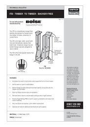
We are pleased to present you with the 2013 Anchors for <strong>Masonry</strong><br />
<strong>and</strong> <strong>Concrete</strong> product catalogue.<br />
Testing Innovation <strong>and</strong> Performance<br />
<strong>Simpson</strong> <strong>Strong</strong>-<strong>Tie</strong>’s work has led to the creation of many anchor products<br />
that significantly improve the safety of homes, buildings, <strong>and</strong> other structures.<br />
Our state-of-the-art laboratory facilities are constantly testing new <strong>and</strong><br />
existing products to provide you with the best connecting <strong>and</strong> anchoring<br />
solutions <strong>and</strong> with the information you need in order to design with <strong>and</strong><br />
properly install our products.<br />
Technical Approvals<br />
Knowing that our products are extensively tested provides you with the<br />
reassurance that they will perform in the toughest conditions. Many of the<br />
products contained in this catalogue have been used in the most dem<strong>and</strong>ing<br />
safety-oriented applications such as nuclear power plants. We strive to<br />
ensure that our products are compliant with the highest European Technical<br />
Approvals for cracked <strong>and</strong> non cracked concrete.<br />
Customer Support<br />
The quality <strong>and</strong> variety of our product line provides engineers <strong>and</strong><br />
builders with design flexibility while offering reliable <strong>and</strong> proven performance.<br />
In addition, customers can count on our engineering technical support,<br />
experienced field representatives <strong>and</strong> training programs.<br />
www.strongtie.co.uk<br />
European Technical Approval<br />
Telephone: 01827 255600 | Visit: www.strongtie.co.uk<br />
2
CONTENTS<br />
Page<br />
Expansion <strong>and</strong> Undercut Anchor Systems<br />
WA, BOAX-II THROUGHBOLT 6-13<br />
Adhesive Anchor Systems<br />
POLY-GP 14-15<br />
AT-HP 16-18<br />
SET-XP 19-21<br />
KLS & KLP 22-25<br />
LMAS THREADED STUD 27<br />
C-ANCHORS-2013 © SIMPSON STRONG-TIE ®<br />
Accessories<br />
Applicator Guns, Brushes, Nozzles, Sleeves 26-27<br />
<strong>Simpson</strong> <strong>Strong</strong>-<strong>Tie</strong> ® reserves the right to change specifications, designs, <strong>and</strong> models without notice or liability for such changes.<br />
3
ANCHOR SELECTION GUIDE<br />
Page<br />
Anchoring<br />
Principle<br />
Cracked<br />
<strong>Concrete</strong><br />
Non-Cracked<br />
<strong>Concrete</strong><br />
Hollow<br />
<strong>Masonry</strong><br />
Type<br />
BOAX-II 8 • •<br />
WEDGE ANCHOR 6 •<br />
UNDERCUT ANCHOR 14 • •<br />
POLY-GP 18 •<br />
AT-HP 20 • •<br />
SET-XP 23 • •<br />
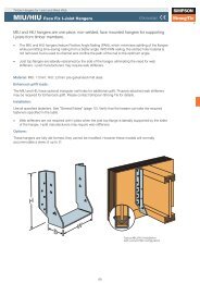
Expansion Anchor Systems Adhesive Anchor Systems Undercut Anchor Systems<br />
This type of anchor transfers load into<br />
the base material through friction grip<br />
that is established between the<br />
anchor’s expansion sleeve <strong>and</strong> the<br />
sidewalls of the drilled hole.<br />
This occurs when the anchor is set <strong>and</strong><br />
the cone is drawn into the expansion<br />
sleeve. Expansion anchors pro vide a<br />
reliable <strong>and</strong> economical fixing system.<br />
This type of anchor consists of a chemical<br />
mortar <strong>and</strong> a threaded metal stud. After<br />
installation a chemical reaction takes place<br />
that secures the stud in place <strong>and</strong> the<br />
chemical bonds to the sidewalls of the drilled<br />
hole.<br />
This system does not produce expansion<br />
forces, <strong>and</strong> therefore allows for smaller edge<br />
distances <strong>and</strong> spacings.<br />
This type of anchor transfers load into the base<br />
material through mechanical interlock with an<br />
undercut that is formed in the base material.<br />
The undercut can be formed before or during<br />
setting of the anchor.<br />
These systems have very high reliability <strong>and</strong><br />
performance.<br />
Tension Zone Anchor<br />
This anchor is suitable<br />
<strong>and</strong> approved for use<br />
in cracked (tension<br />
zone) <strong>and</strong> non-cracked<br />
(compression zone)<br />
concrete.<br />
Compression Zone<br />
Anchor<br />
This anchor is suitable<br />
<strong>and</strong> approved for<br />
use in non-cracked<br />
(compression zone)<br />
concrete.<br />
Hollow <strong>Masonry</strong><br />
This anchor is suitable<br />
<strong>and</strong> approved for use<br />
in solid masonry<br />
meet ing DIN 1053.<br />
Solid <strong>Masonry</strong><br />
This anchor is suitable<br />
<strong>and</strong> approved for use<br />
in solid masonry<br />
meet ing DIN 1053.<br />
European<br />
Technical Approval<br />
This anchor has<br />
been approved<br />
for construction<br />
applications in<br />
accordance with<br />
European Technical<br />
Approval Guidelines<br />
(ETAG).<br />
European<br />
Conformity Mark<br />
This product meets<br />
the requirements<br />
of the European<br />
Technical Approval <strong>and</strong><br />
can be used without<br />
restriction in the<br />
European Union.<br />
4
ANCHOR SELECTION GUIDE<br />
Solid<br />
<strong>Masonry</strong><br />
ETA-Approval<br />
Fire<br />
Resistance<br />
Sprinklers<br />
Steel,<br />
Zinc Plated<br />
Load Range<br />
Calculation<br />
Software<br />
Corrosion<br />
Resistance<br />
European Technical Approval<br />
Option 1 • • •<br />
Option 7<br />
Option 1 • • •<br />
• <strong>Masonry</strong> •<br />
•<br />
Option 8, <strong>Masonry</strong><br />
<strong>and</strong> Rebar<br />
Option 1<br />
•<br />
•<br />
•<br />
1.8–21.4<br />
kN<br />
3.4–26.7<br />
kN<br />
2.4–30.8<br />
kN<br />
0.3–0.7<br />
kN<br />
9.1–54.8<br />
kN<br />
5.4–57.4<br />
kN<br />
• •<br />
•<br />
•<br />
• •<br />
• •<br />
•<br />
Corrosion Resistance<br />
Approved Anchors<br />
C-ANCHORS-2013 © SIMPSON STRONG-TIE ®<br />
Corrosion is the destruction of metal through chemical or<br />
electrochemical attack by the environment. In most indoor<br />
conditions carbon steel anchors with zinc plating provide sufficient<br />
corrosion resistance. Stainless steel (A4) anchors are usually<br />
suitable for outdoor or damp indoor conditions. Stainless steel<br />
anchors with special corrosion resistant properties are necessary<br />
for aggressive conditions such as roadway tunnels or chloride<br />
atmospheres.<br />
To ensure that an anchor is capable of resisting the intended external<br />
loads, the anchor must be suitable for the intended application <strong>and</strong><br />
installed in accordance with the manufacturer’s recommended<br />
installation instructions.<br />
Anchors with independent technical approvals (such as DIBt or ETA)<br />
have demonstrated suitable behavior <strong>and</strong> performance<br />
for use in construction applications.<br />
Fire Resistance<br />
Suitable for use in fire<br />
protection applications.<br />
This anchor meets the<br />
requirements of VdS<br />
CEA 4001.<br />
Available in carbon steel,<br />
zinc plated <strong>and</strong> blue<br />
passivated.<br />
Permissible tension load.<br />
Calculation software.<br />
Corrosion Resistance.<br />
5
WA THROUGHBOLT<br />
ETA Option 7 Approved throughbolt for simple <strong>and</strong><br />
economical applications.<br />
The WA Throughbolt range. Providing an economical yet<br />
high performance fixing for installations with small space<br />
<strong>and</strong> edge distances in non-cracked concrete.<br />
Features <strong>and</strong> Benefits:<br />
• ETA Option 7 Approved (Non-Cracked <strong>Concrete</strong>)<br />
• Wide range of sizes from M6 to M20<br />
• M6 to M10 sizes require 100mm concrete thickness<br />
• High load capacity<br />
• Optimised design for fast installation<br />
• Suitable for small spacings between anchors<br />
• Suitable for small edge distances<br />
• Economical cost<br />
90°<br />
Drill hole Clean hole (blowing) Insert anchor through the<br />
fixture<br />
Apply recommended<br />
installation torque with a<br />
calibrated torque wrench<br />
6
Expansion Anchor Systems<br />
WA THROUGHBOLT<br />
ETA - 11/0080<br />
Material: Carbon Steel, Zinc Plated <strong>and</strong> Passivated<br />
Thread size M6 M8 M10 M12 M16 M20 (4)<br />
Effective embedment depth (h ef<br />
) [mm] 40 45 50 65 80 100<br />
Model WA 6/… WA 8/… WA 10/… WA 12/… WA 16/… WA 20/…<br />
Recommended tension loads for single anchors with no edge distances or spacings<br />
1) 5)<br />
N rec<br />
concrete 3) C40/50 [kN] 5.0 8.1 10.7 17.8 24.3 19.9<br />
C20/25 [kN] 4.3 5.7 7.6 12.6 17.2 19.9<br />
Non-cracked C30/37 [kN] 4.6 7.0 9.3 15.4 21.0 19.9<br />
C50/60 [kN] 5.3 8.9 11.8 19.5 26.7 19.9<br />
Recommended shear load for single anchors with no edge distances or spacings<br />
1) 2)<br />
V rec<br />
Non-cracked<br />
concrete 3)<br />
C20/25 [kN] 3.4 5.4 8.5 14.3 26.9 26.7<br />
C30/37 [kN] 3.4 5.4 9.7 14.3 26.9 26.7<br />
C40/50 [kN] 3.4 5.4 9.7 14.3 26.9 26.7<br />
C50/60 [kN] 3.4 5.4 9.7 14.3 26.9 26.7<br />
1. The recommended loads have been calculated using the partial safety factors for resistances stated in ETA-approval(s) <strong>and</strong> with a partial safety factor for actions of γᵧF=1.4. The loading figures<br />
are valid for unreinforced concrete <strong>and</strong> reinforced concrete with a rebar spacing s ≥ 15 cm (any diameter) or with a rebar spacing s ≥ 10 cm, if the rebar diameter is 10 mm or smaller.<br />
2. The figures for shear are based on a single anchor without influence of concrete edges. <strong>For</strong> anchorages close to edges (c ≤ max [10 hef; 60d]) the concrete edge failure shall be checked per<br />
ETAG 001, Annex C, design method A.<br />
3. <strong>Concrete</strong> is considered non-cracked when the tensile stress within the concrete is σσ L + σσ R ≤ 0. In the absence of detailed verification σσ R = 3 N/mm² can be assumed (σσ L equals the tensile<br />
stress within the concrete induced by external loads, anchors loads included).<br />
4. Not included in the approval ETA-11/0080 - Option 7.<br />
5. <strong>For</strong> combined tension <strong>and</strong> shear loads or anchor groups <strong>and</strong>/or in case of edge influence, a calculation per ETAG 001, Annex C, design method A shall be performed. <strong>For</strong> details see<br />
ETA - approval(s).<br />
With Hex Nut <strong>and</strong> Washer - Material: Carbon Steel, Zinc Plated <strong>and</strong> Blue Passivated<br />
C-ANCHORS-2013 © SIMPSON STRONG-TIE ®<br />
Type<br />
Item<br />
Code<br />
WA 6/5 (M6 x 60) WA06060 •<br />
ETA<br />
Thread Size<br />
Ø × Depth of<br />
Drilled Hole<br />
Max. Fixture<br />
Thickness<br />
Ø Fixture<br />
Hole<br />
Eff. Embedment<br />
Depth<br />
Length<br />
Thread<br />
Length<br />
d o<br />
x h 1<br />
t fix<br />
d f<br />
h ef<br />
L F<br />
mm mm mm mm mm mm<br />
WA 6/10 (M6 x 65) WA06065 • 10 65 30 100<br />
M6 6 x 55<br />
7 40<br />
WA 6/20 (M6 x 75) WA06075 • 20 75 35 100<br />
5<br />
Box<br />
Qty<br />
60 30 100<br />
WA 6/30 (M6 x 85) WA06085 • 30 85 40 100<br />
WA 8/5 (M8 x 68) WA08068 •<br />
WA 8/30 (M8 x 93) WA08093 • 30 93 50 50<br />
M8 8 x 65<br />
9 45<br />
WA 8/40 (M8 x 103) WA08103 • 40 103 50 50<br />
5<br />
68 40 50<br />
WA 8/10 (M8 x 73) WA08073 • 10 73 45 50<br />
WA 8/20 (M8 x 83) WA08083 • 20 83 45 50<br />
WA 8/50 (M8 x 113) WA08113 • 50 113 60 50<br />
WA 8/70 (M8 x 133) WA08133 • 70 133 85 50<br />
WA 8/100 (M8 x 163) WA08163 • 100 163 100 50<br />
WA 10/5 (M10 x 78) WA10078 •<br />
WA 10/30 (M10 x 103) WA10103 • 30 103 50 50<br />
M10 10 x 70<br />
12 50<br />
WA 10/40 (M10 x 113) WA10113 • 40 113 60 50<br />
5<br />
78 40 50<br />
WA 10/10 (M10 x 83) WA10083 • 10 83 40 50<br />
WA 10/20 (M10 x 93) WA10093 • 20 93 50 50<br />
WA 10/50 (M10 x 123) WA10123 • 50 123 60 50<br />
WA 10/70 (M10 x 143) WA10143 • 70 143 70 50<br />
WA 10/100 (M10 x 173) WA10173 • 100 173 80 50<br />
WA 12/5 (M12 x 104) WA12104 •<br />
WA 12/50 (M12 x 149) WA12149 • M12 12 x 90<br />
50 14 65<br />
149 100 25<br />
5<br />
104 60 25<br />
WA 12/10 (M12 x 109) WA12109 • 10 109 60 25<br />
WA 12/20 (M12 x 119) WA12119 • 20 119 70 25<br />
WA 12/30 (M12 x 129) WA12129 • 30 129 70 25<br />
WA 12/40 (M12 x 139) WA12139 • 40 139 80 25<br />
WA 12/80 (M12 x 179) WA12179 • 80 179 110 25<br />
WA 12/100 (M12 x 199) WA12199 • 100 199 110 25<br />
WA 12/120 (M12 x 219) WA12219 • 120 219 125 25<br />
WA 12/140 (M12 x 239) WA12239 • 140 239 125 25<br />
WA 12/160 (M12 x 259) WA12259 • 160 259 125 20<br />
WA 16/30 (M16 x 151) WA16151 •<br />
WA 16/80 (M16 x 201) WA16201 • M16 16 x 110<br />
80 18 80<br />
201 100 10<br />
30<br />
151 80 20<br />
WA 16/50 (M16 x 171) WA16171 • 50 171 80 20<br />
WA 16/100 (M16 x 221) WA16221 • 100 221 100 10<br />
WA 16/140 (M16 x 261) WA16261 • 140 261 110 10<br />
WA 20/30 (M20 x 173) WA20173 -<br />
WA 20/50 (M20 x 193) WA20193 - 50 193 100 10<br />
M20 20 x 130<br />
22 100<br />
WA 20/80 (M20 x 223) WA20223 - 80 223 125 10<br />
30<br />
173 100 10<br />
WA 20/120 (M20 x 263) WA20263 - 120 263 150 10<br />
Spacing, Edge Distance <strong>and</strong> Member Thickness<br />
M6 M8 M10 M12 M16 M20 (4)<br />
Effective Embedment Depth h ef mm 40 45 50 65 80 100<br />
Characteristic Spacing S cr,N mm 120 135 150 195 240 300<br />
Minimum Spacing S min mm 30 40 50 70 90 120<br />
Characteristic Edge Distance Ccr,N mm 60 67.5 75 97.5 120 150<br />
Minimum Edge Distance C min mm 40 40 50 70 90 120<br />
Minimum Member Thickness h min mm 100 100 120 140 170 180<br />
7
THROUGHBOLT BOAX-II<br />
<strong>For</strong> simple <strong>and</strong> economical applications. BOAX-II is<br />
ETA Option 1 approved.<br />
Function: Application of the installation torque draws the cone end of<br />
the stud into the expansion clip. The expansion clip exp<strong>and</strong>s <strong>and</strong><br />
develops a frictional grip with the sidewalls of the hole. This gives the<br />
anchor its resistance to tension loads.<br />
Benefits:<br />
• Economical anchor for medium-duty loads<br />
• Approved for use in cracked <strong>and</strong> non-cracked concrete<br />
8
Expansion Anchor Systems<br />
BOAX-II ETA - 08/0276<br />
CONSTRUCTION:<br />
BoAX-II<br />
with hex nut <strong>and</strong> washer<br />
MATERIAL:<br />
Carbon steel, zinc plated <strong>and</strong> blue passivated<br />
A4 stainless steel<br />
R 120<br />
BASE MATERIAL:<br />
Cracked <strong>and</strong> non-cracked concrete: C20/25 to C50/60 (B25 to B55)<br />
Also suitable for high density natural stones (σ D<br />
≥ 25 N/mm 2 )<br />
APPROVALS:<br />
ETA-08/0276 - Option 1: M8-M16, carbon steel, zinc plated<br />
ETA-08/0276 - Option 1: M8-M16, A4 stainless steel<br />
LOAD RANGE:<br />
Tension:<br />
Shear:<br />
N perm<br />
= 1.8 - 21.4 [kN]<br />
V perm<br />
= 1.8 - 22.4 [kN]<br />
PRODUCT RANGE:<br />
BoAX-II: M8 - M16, carbon steel, zinc plated <strong>and</strong> blue passivated<br />
BoAX-II A4: M8 - M16, A4 stainless steel<br />
APPLICATIONS:<br />
Steel construction<br />
Railing<br />
Brackets<br />
Facades<br />
Cable trays<br />
Ladders<br />
BENEFITS:<br />
Economical anchor for medium duty loads<br />
Less drilling effort: Anchor diameter = Drill bit diameter<br />
PRODUCT DESCRIPTION:<br />
The throughbolt anchor is installed through the fixture<br />
Torquing draws the cone end of the stud into the expansion clip. The expansion clip exp<strong>and</strong>s <strong>and</strong><br />
develops a frictional grip with the sidewalls of the hole.<br />
C-ANCHORS-2013 © SIMPSON STRONG-TIE ®<br />
INSTALLATION:<br />
Through-fix installation<br />
90°<br />
Drill hole Clean hole (blowing) Insert anchor<br />
through fixture<br />
Apply recommended<br />
fastening torque with a<br />
calibrated torque-wrench<br />
9
Expansion Anchor Systems<br />
BOAX-II<br />
Carbon steel, zinc plated<br />
THROUGHBOLT BOAX-II<br />
With hex nut <strong>and</strong> washer<br />
Material: Carbon steel, zinc plated <strong>and</strong> blue passivated<br />
Approval: ETA-08/0276 (M8 - M16) - Option 1<br />
Type<br />
Order Code<br />
Thread<br />
Size<br />
Ø x<br />
Depth of<br />
Drilled Hole<br />
Max.<br />
Fixture<br />
Thickness<br />
Ø Fixture<br />
Hole<br />
Eff.<br />
Embedment<br />
Depth<br />
Total<br />
Length<br />
d o x h 1 t fix d f h ef L f<br />
Thread<br />
Length Weight Box<br />
Quantity<br />
[mm] [mm] [mm] [mm] [mm] [mm] [mm] [kg/100 pcs] [pcs]<br />
BoAX-II 8/10 BOAXII08045010 M8 8 x 60 10 9 45 72 32 2.91 50<br />
BoAX-II 8/30 BOAXII08045030 M8 8 x 60 30 9 45 92 52 3.53 50<br />
BoAX-II 8/50 BOAXII08045050 M8 8 x 60 50 9 45 112 72 4.14 40<br />
BoAX-II 8/85 BOAXII08045085 M8 8 x 60 85 9 45 147 107 5.21 40<br />
BoAX-II 10/10 BOAXII10060010 M10 10 x 75 10 12 60 92 47 5.92 40<br />
BoAX-II 10/20 BOAXII10060020 M10 10 x 75 20 12 60 102 57 6.41 25<br />
BoAX-II 10/30 BOAXII10060030 M10 10 x 75 30 12 60 112 67 6.91 25<br />
BoAX-II 10/50 BOAXII10060050 M10 10 x 75 50 12 60 132 87 7.89 25<br />
BoAX-II 10/80 BOAXII10060080 M10 10 x 75 80 12 60 162 115 9.37 25<br />
BoAX-II 12/5 BOAXII12070005 M12 12 x 90 5 14 70 103 53 9.53 20<br />
BoAX-II 12/20 BOAXII12070020 M12 12 x 90 20 14 70 118 68 10.60 20<br />
BoAX-II 12/30 BOAXII12070030 M12 12 x 90 30 14 70 128 78 11.31 20<br />
BoAX-II 12/50 BOAXII12070050 M12 12 x 90 50 14 70 148 98 12.73 20<br />
BoAX-II 12/65 BOAXII12070065 M12 12 x 90 65 14 70 163 113 13.80 20<br />
BoAX-II 12/80 BOAXII12070080 M12 12 x 90 80 14 70 178 115 14.87 20<br />
BoAX-II 16/5 BOAXII16085005 M16 16 x 110 5 18 85 123 65 20.16 10<br />
BoAX-II 16/20 BOAXII16085020 M16 16 x 110 20 18 85 138 80 22.17 10<br />
BoAX-II 16/50 BOAXII16085050 M16 16 x 110 50 18 85 168 110 26.19 10<br />
BoAX-II 16/60 BOAXII16085060 M16 16 x 110 60 18 85 178 115 27.53 10<br />
10
Expansion Anchor Systems<br />
BOAX-II TECHNICAL DATA<br />
Carbon steel, zinc plated<br />
Permissible loads for single anchors with no influencing edge distances or spacings. Loads are calculated using partial safety<br />
factors from ETAG 001 <strong>and</strong> the characteristic anchor <strong>and</strong> installation data from this catalogue.<br />
Design calculations shall follow the requirements of ETA-08/0276.<br />
Material: Carbon steel, zinc plated <strong>and</strong> blue passivated<br />
Thread size M8 M10 M12 M16<br />
Effective embedment depth (h ef ) [mm] 45 60 70 85<br />
Type BoA-... BoAX-II 8/… BoAX-II 10/… BoAX-II 12/… BoAX-II 16/…<br />
1) 4)<br />
Permissible tension loads<br />
N perm<br />
Cracked<br />
<strong>Concrete</strong><br />
C20/25 [kN] 2.0 3.6 4.8 9.5<br />
C30/37 [kN] 2.2 4.0 5.3 10.5<br />
C40/50 [kN] 2.4 4.3 5.8 11.4<br />
C50/60 [kN] 2.6 4.6 6.1 12.2<br />
Non-cracked C20/25 [kN] 3.6 6.3 7.9 16.7<br />
concrete 3) C30/37 [kN] 3.9 6.9 8.7 18.4<br />
C40/50 [kN] 4.3 7.6 9.5 20.0<br />
C50/60 [kN] 4.6 8.1 10.1 21.4<br />
1) 2) 4)<br />
Permissible shear loads<br />
V perm<br />
Cracked<br />
<strong>Concrete</strong><br />
C20/25 [kN] 4.8 8.7 11.0 21.0<br />
C30/37 [kN] 4.8 8.7 11.0 21.0<br />
C40/50 [kN] 4.8 8.7 11.0 21.0<br />
C50/60 [kN] 4.8 8.7 11.0 21.0<br />
Non-cracked C20/25 [kN] 4.8 8.7 11.0 21.0<br />
concrete 3) C30/37 [kN] 4.8 8.7 11.0 21.0<br />
C40/50 [kN] 4.8 8.7 11.0 21.0<br />
C50/60 [kN] 4.8 8.7 11.0 21.0<br />
Permissible bending moments 1)<br />
4)<br />
M zul [Nm] 10.0 22.9 34.3 88.6<br />
Spacings, edge distances <strong>and</strong> member thicknesses<br />
Effective embedment depth h ef [mm] 45 60 70 85<br />
Characteristic spacing 4) s cr,N [mm] 135 180 210 255<br />
Minimum spacing s min [mm] 50 55 60 70<br />
Characteristic edge distance 4) c cr,N [mm] 68 90 105 128<br />
Minimum edge distance c min [mm] 50 50 55 85<br />
Minimum member thickness h min [mm] 100 120 140 170<br />
Installation data<br />
Drill hole diameter d 0 [mm] 8 10 12 16<br />
Drill hole depth h 1 [mm] 60 75 90 110<br />
Clearance hole in the fixture d f [mm] 9 12 14 18<br />
Width across flats sw [mm] 13 17 19 24<br />
Installation torque T inst [Nm] 20 35 50 120<br />
Installed anchor<br />
L<br />
f<br />
sw<br />
Tinst<br />
C-ANCHORS-2013 © SIMPSON STRONG-TIE ®<br />
d0<br />
1) The permissible loads have been calculated using the partial safety factors for resistances stated in the ETA-approval <strong>and</strong> a partial safety factor for<br />
actions of γ F = 1.4.<br />
The permissible loads are valid for unreinforced concrete <strong>and</strong> reinforced concrete with a rebar spacing s ≥ 15 cm <strong>and</strong> reinforced concrete with a rebar<br />
2) The permissible shear loads are based on a single anchor without influencing concrete edges. <strong>For</strong> shear loads applied close to an edge (c < 10 h ef or <<br />
60 d) concrete edge failure must be checked per ETAG 001, Annex C, design method A.<br />
3) <strong>Concrete</strong> is considered non-cracked when the tensile stress within the concrete is σ L + σ R ≤ 0. In the absence of detailed verification σ R = 3 N/mm 2 can<br />
be assumed (σ L equals the tensile stress within the concrete as a result of external loads, forces on anchors included).<br />
4) <strong>For</strong> combined tension <strong>and</strong> shear loads or anchor groups <strong>and</strong>/or in case of edge influence, a calculation per ETAG 001, Annex C, design method A<br />
shall be performed. <strong>For</strong> details see ETA - approval(s).<br />
h<br />
min<br />
h<br />
1<br />
h<br />
ef<br />
t fix<br />
df<br />
11
Expansion Anchor Systems<br />
BOAX-II<br />
A4 stainless steel<br />
THROUGHBOLT BOAX-II A4<br />
With hex nut <strong>and</strong> washer<br />
Material: A4 stainless steel<br />
Approval: ETA-08/0276 (M8 - M16) - Option 1<br />
Type<br />
Order Code<br />
Thread<br />
Size<br />
Ø x<br />
Depth of<br />
Drilled Hole<br />
Max.<br />
Fixture<br />
Thickness<br />
Ø Fixture<br />
Hole<br />
Eff.<br />
Embedment<br />
Depth<br />
Total<br />
Length<br />
Thread<br />
Length<br />
d o x h 1 t fix d f h ef L f<br />
Weight<br />
Box<br />
Quantity<br />
[mm] [mm] [mm] [mm] [mm] [mm] [mm] [kg/100 pcs] [pcs]<br />
BoAX-II 8/10 A4 BOAXII08045010A4 M8 8 x 60 10 9 45 72 32 2.9 50<br />
BoAX-II 8/30 A4 BOAXII08045030A4 M8 8 x 60 30 9 45 92 52 3.5 50<br />
BoAX-II 8/50 A4 BOAXII08045050A4 M8 8 x 60 50 9 45 112 72 4.1 40<br />
BoAX-II 10/10 A4 BOAXII10060010A4 M10 10 x 75 10 12 60 92 47 5.9 40<br />
BoAX-II 10/20 A4 BOAXII10060020A4 M10 10 x 75 20 12 60 102 57 6.4 25<br />
BoAX-II 10/30 A4 BOAXII10060030A4 M10 10 x 75 30 12 60 112 67 6.9 25<br />
BoAX-II10/50 A4 BOAXII10060050A4 M10 10 x 75 50 12 60 132 87 7.9 25<br />
BoAX-II 12/5 A4 BOAXII12070005A4 M12 12 x 90 5 14 70 103 53 9.5 20<br />
BoAX-II 12/20 A4 BOAXII12070020A4 M12 12 x 90 20 14 70 118 68 10.6 20<br />
BoAX-II 12/30 A4 BOAXII12070030A4 M12 12 x 90 30 14 70 128 78 11.3 20<br />
BoAX-II 12/50 A4 BOAXII12070050A4 M12 12 x 90 50 14 70 148 98 12.7 20<br />
BoAX-II 12/65 A4 BOAXII12070065A4 M12 12 x 90 65 14 70 163 113 13.8 20<br />
BoAX-II 16/5 A4 BOAXII16085005A4 M16 16 x 110 5 18 85 123 65 20.2 10<br />
BoAX-II 16/20 A4 BOAXII16085020A4 M16 16 x 110 20 18 85 138 80 22.2 10<br />
BoAX-II 16/50 A4 BOAXII16085050A4 M16 16 x 110 50 18 85 168 110 26.2 10<br />
12
Expansion Anchor Systems<br />
BOAX-II TECHNICAL DATA<br />
A4 stainless steel<br />
Permissible loads for single anchors with no influencing edge distances or spacings. Loads are calculated using partial safety<br />
factors from ETAG 001 <strong>and</strong> the characteristic anchor <strong>and</strong> installation data from this catalogue.<br />
Design calculations shall follow the requirements of ETA-08/0276.<br />
Material: A4 stainless steel<br />
Thread size M8 M10 M12 M16<br />
Effective embedment depth (h ef ) [mm] 45 60 70 85<br />
Type BoA-... BoAX-II 8/… BoAX-II 10/… BoAX-II 12/… BoAX-II 16/…<br />
Permissible tension loads 1)<br />
N perm<br />
Cracked<br />
<strong>Concrete</strong><br />
C20/25 [kN] 2.0 3.6 4.8 9.5<br />
C30/37 [kN] 2.2 4.0 5.3 10.5<br />
C40/50 [kN] 2.4 4.3 5.8 11.4<br />
C50/60 [kN] 2.6 4.6 6.1 12.2<br />
Non-cracked C20/25 [kN] 3.6 6.3 7.9 16.7<br />
concrete 3) C30/37 [kN] 3.9 6.9 8.7 18.4<br />
C40/50 [kN] 4.3 7.6 9.5 20.0<br />
C50/60 [kN] 4.6 8.1 10.1 21.4<br />
1) 2)<br />
Permissible shear loads<br />
V perm<br />
Cracked<br />
<strong>Concrete</strong><br />
C20/25 [kN] 5.2 8.1 11.9 22.4<br />
C30/37 [kN] 5.2 8.1 11.9 22.4<br />
C40/50 [kN] 5.2 8.1 11.9 22.4<br />
C50/60 [kN] 5.2 8.1 11.9 22.4<br />
Non-cracked C20/25 [kN] 5.2 8.1 11.9 22.4<br />
concrete 3) C30/37 [kN] 5.2 8.1 11.9 22.4<br />
C40/50 [kN] 5.2 8.1 11.9 22.4<br />
C50/60 [kN] 5.2 8.1 11.9 22.4<br />
Permissible bending moments 1)<br />
4)<br />
M zul [Nm] 10.5 21.4 37.6 95.2<br />
Spacings, edge distances <strong>and</strong> member thicknesses<br />
Effective embedment depth h ef [mm] 45 60 70 85<br />
Characteristic spacing 4) s cr,N [mm] 135 180 210 255<br />
Minimum spacing s min [mm] 50 55 60 70<br />
Characteristic edge distance 4) c cr,N [mm] 68 90 105 128<br />
Minimum edge distance c min [mm] 50 50 55 85<br />
Minimum member thickness h min [mm] 100 120 140 170<br />
Installation data<br />
Drill hole diameter d 0 [mm] 8 10 12 16<br />
Drill hole depth h 1 [mm] 60 75 90 110<br />
Clearance hole in the fixture d f [mm] 9 12 14 18<br />
Width across flats sw [mm] 13 17 19 24<br />
Installation torque T inst [Nm] 20 35 50 120<br />
Installed anchor<br />
L<br />
f<br />
sw<br />
Tinst<br />
C-ANCHORS-2013 © SIMPSON STRONG-TIE ®<br />
d0<br />
1) The permissible loads have been calculated using the partial safety factors for resistances stated in the ETA-approval <strong>and</strong> a partial safety factor for<br />
actions of γ F = 1.4.<br />
The permissible loads are valid for unreinforced concrete <strong>and</strong> reinforced concrete with a rebar spacing s ≥ 15 cm <strong>and</strong> reinforced concrete with a rebar<br />
2) The permissible shear loads are based on a single anchor without influencing concrete edges. <strong>For</strong> shear loads applied close to an edge (c < 10 h ef or <<br />
60 d) concrete edge failure must be checked per ETAG 001, Annex C, design method A.<br />
3) <strong>Concrete</strong> is considered non-cracked when the tensile stress within the concrete is σ L + σ R ≤ 0. In the absence of detailed verification σ R = 3 N/mm 2 can<br />
be assumed (σ L equals the tensile stress within the concrete as a result of external loads, forces on anchors included).<br />
4) If spacings or edge distances become smaller than the characteristic values (i.e. s ≤ s cr,N<br />
<strong>and</strong>/or c ≤ c cr,N<br />
) a calculation per ETAG 001, Annex C, design<br />
method A must be performed.<br />
h<br />
min<br />
h<br />
1<br />
h<br />
ef<br />
t fix<br />
df<br />
13
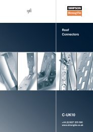
POLY-GP<br />
CHEMICAL ANCHOR SYSTEM<br />
Styrene free general purpose resin.<br />
POLY-GP is a<br />
styrene-free<br />
polyester resin<br />
specially formulated<br />
for light or medium<br />
duty fixings in<br />
hollow or solid base<br />
materials.<br />
Easy to use <strong>and</strong> fast<br />
curing, it enables<br />
good performance<br />
when used in<br />
applications such as<br />
fixing architectural<br />
steelwork, cable<br />
trays, h<strong>and</strong> rails <strong>and</strong><br />
gates.<br />
• Styrene free.<br />
• Use in solid or<br />
hollow masonry<br />
products.<br />
• Non-flammable.<br />
14
Adhesive Systems<br />
POLY-GP<br />
POLY-GP is a styrene-free polyester resin specially formulated to light or medium duty fixings in hollow or<br />
solid base materials. It's easy to use <strong>and</strong> fast curing. It enables good performance when used in basic jobs<br />
such as fixing a shutter, a satelllite dish, a boiler, shelves or a gate.<br />
POLY-GP is non-flammable product.<br />
Cartridges available are adapted to the needs of anyone who has a universal manual dispensing tool (such as<br />
a silicone dispensing tool) with the 300 ml cartridge.<br />
DAZ 0816/1<br />
Reference<br />
Contents<br />
POLY-GP300-UK<br />
300 ml<br />
Two mixers are supplied with each cartridge.<br />
BENEFITS:<br />
• Fast curing<br />
• Low odour<br />
• Non-flammable product<br />
• Good performance in hollow <strong>and</strong> solid base material<br />
CERTIFICATION: SOCOTEC Hollow blocks DAZ 0816/1<br />
MATERIAL:<br />
Hollow or solid bricks<br />
APPLICATIONS:<br />
• Blinds<br />
• Hinges<br />
• Air-conditioners<br />
• Satellite dishes<br />
• Boilers<br />
POLY-GP<br />
300 ml<br />
Beige<br />
Colour<br />
CURING SCHEDULE:<br />
Let anchor fully cure without disturbing<br />
Temp. of Resin °c Temp. of Support °c Working Time Curing time<br />
+5°c -5°c 25 mins 4 h<br />
+5°c 0°c 15 mins 3 h<br />
+5°c +5°c 12 mins 2 h 30 mins<br />
+10°c +10°c 8 mins 1 h 15 mins<br />
+15°c +15°c 7 mins 55 mins<br />
+20°c +20°c 4 mins 30 mins<br />
+30°c +30°c 2 mins 20 mins<br />
Working Loads<br />
Working loads limit performance details have been determined from minimal values of tests carried out in<br />
Laboratories. Those minimal values take into account a minimal safety of 4 (SOCOTEC-DAZ 0816/1).<br />
Strength limits take into account the position of the anchors in the material <strong>and</strong> the respect of the installation<br />
instructions. <strong>For</strong> hollow materials of unknown resitance, tests on construction sites are necessary<br />
(according to BS 8539).<br />
Tension Hollow block (kN) Hollow concrete (kN)<br />
Threaded Rod (M8 - M10 - M12) 0.6 0.9<br />
Shear Hollow block (kN) Hollow concrete (kN)<br />
Threaded Rod (M8 - M10 - M12) 1.5 1.5<br />
LMAS<br />
Zinc-plated steel<br />
See page 31.<br />
Graduated mixer MN1<br />
Sleeve SH<br />
See Page 30<br />
Installation Data<br />
C-ANCHORS-2013 © SIMPSON STRONG-TIE ®<br />
Material<br />
Threaded Rod<br />
diam xL (mm)<br />
Drill diam<br />
(mm)<br />
Sleeve<br />
diam xL (mm)<br />
Drill depth<br />
(mm)<br />
Tightening<br />
torque (Nm)<br />
Number of<br />
pressure<br />
Hollow block M8x140 16 16x85 90 4 8<br />
Hollow block M10x140 16 16x85 90 6 8<br />
Hollow block M12x140 16 16x85 90 8 8<br />
Hollow concrete M8x160 16 16x130 135 4 13<br />
Hollow concrete M10x160 16 16x130 135 6 13<br />
Hollow concrete M12x160 16 16x130 135 8 13<br />
Safety <strong>and</strong> environment<br />
We care about developing products that are user-safe <strong>and</strong> environmentally respectful<br />
when properly h<strong>and</strong>led <strong>and</strong> disposed of. Once empty, dispose of this cartridge in a<br />
hazardous waste disposal skip.<br />
Xi irritant O Oxidising<br />
Observe these safety precautions (Contains dibenzoyl peroxide):<br />
R52/53 Harmful to aquatic organisms, may cause long-term adverse effects in the aquatic environment (A).<br />
R43 May cause sensitisation by skin contact (B). R7 May cause fire (B). S3/14 Keep in a cool place away<br />
from-combustible or reducing materials-acids-oxidation catalysts (B). S36/37/39 Wear suitable protective<br />
clothing, gloves <strong>and</strong> eye/face protection (B). S7 Keep container tightly closed (B). S60 This material <strong>and</strong> its<br />
container must be disposed of as hazardous waste (B).<br />
15
AT-HP<br />
HIGH PERFORMANCE<br />
Methacrylate resin for threaded rod <strong>and</strong> rebar.<br />
AT-HP is a styrene<br />
free methacrylate<br />
resin suitable for<br />
high performance<br />
fixing applications<br />
of threaded rod <strong>and</strong><br />
rebar into concrete<br />
(ETA approved for<br />
each application).<br />
Easy to dispense<br />
<strong>and</strong> fast curing,<br />
specially designed<br />
for structural fixings<br />
<strong>and</strong> construction<br />
uses.<br />
Applications for<br />
metallic racking or<br />
work in reinforced<br />
concrete.<br />
• ETA approve for<br />
masonry <strong>and</strong><br />
rebar.<br />
• Fast curing.<br />
• Low odour.<br />
• Non-flammable.<br />
• High<br />
performance<br />
in threaded<br />
rod <strong>and</strong> rebar<br />
connections.<br />
16
Adhesive Systems<br />
AT-HP TECHNICAL DATA<br />
ETA - 11/0139, ETA-13/0416, ETA-11/0150, ETA-11/0151<br />
AT-HP is a styrene free methacrylate resin suitable for high performance fixing applications of threaded rod<br />
<strong>and</strong> rebar into concrete (double ETA). Easy to dispense <strong>and</strong> fast curing, specially designed for structural<br />
fixings <strong>and</strong> very technical construction sites. Applications for metallic racking or for work in reinforced<br />
concrete.<br />
Cartridges available are adapted to the needs of a craftsman who uses from time to time chemical anchors<br />
(such as a peeler cartridge 160 ml with a silicone gun) or to the needs of a professional<br />
accustomed to chemical fixing <strong>and</strong> who uses a coaxial cartridge in 380 ml.<br />
ETA-13/0416<br />
ETA-11/0150<br />
ETA-11/0151<br />
ETA-11/0139<br />
Reference<br />
Contents<br />
AT-HP<br />
160 ml<br />
AT-HP<br />
280 ml<br />
AT-HP160-UK<br />
160 ml<br />
AT-HP280-UK<br />
280 ml<br />
AT-HP380-UK<br />
380 ml<br />
Two mixers are supplied with each cartridge.<br />
BENEFITS:<br />
• Fast curing<br />
• low odour<br />
• Non-flammable<br />
MATERIAL:<br />
Non-Cracked <strong>Concrete</strong><br />
Solid Bricks<br />
Hollow Blocks<br />
AAC Blocks<br />
AAC Blocks<br />
APPLICATIONS:<br />
• Threaded rod <strong>and</strong> rebar connections<br />
• Racking<br />
• Balconies<br />
• Facade<br />
CERTIFICATION:<br />
AT-HP<br />
380 ml<br />
Grey<br />
WRAS<br />
MA3404/E<br />
0706528<br />
CURING SCHEDULE:<br />
Let anchor fully cure without disturbing<br />
Temperature of Anchorage Base<br />
T anchorage base<br />
Working Time<br />
t gel<br />
Curing Time<br />
t cure<br />
Graduated mixer MN1<br />
C-ANCHORS-2013 © SIMPSON STRONG-TIE ®<br />
-5°C 45 min 9 h<br />
0°C 15 min 4 h<br />
+5°C 12 min 1 h 30 min<br />
+10°C 9 min 60 min<br />
+20°C 4 min 30 min<br />
+30°C 1 min 20 min<br />
Note: temperature of the resin ≥ 5°C.<br />
METHOD OF CLEANING HOLES IN<br />
SOLID BASE MATERIALS:<br />
Normal diameter<br />
Method of cleaning hole<br />
All diameter<br />
2 blow<br />
+ 2 brush<br />
+ 2 blow<br />
+ 2 brush<br />
+ 2 blow<br />
17
Adhesive Systems<br />
AT-HP TECHNICAL DATA<br />
Material: Carbon steel, Grade 5.8, zinc plated <strong>and</strong> blue passivated; A4-70 stainless steel / AT-HP TM<br />
TECHNICAL DATA FOR THREADED ROD FOR FIXINGS IN CONCRETE<br />
Installation parameters<br />
M8 M10 M12 M16 M20<br />
Drill hole diameter, d 0<br />
mm 10 12 14 18 22<br />
Drill hole depth, h 0<br />
mm 64 96 80 120 96 144 128 192 160 240<br />
Clearance hole in the fixture, d f<br />
mm 9 12 14 18 22<br />
Width across flats, sw mm 13 17 19 24 30<br />
Installation torque, T inst<br />
Nm 10 20 40 80 150<br />
Spacings, edge distances <strong>and</strong> member thicknesses<br />
M8 M10 M12 M16 M20<br />
Effective embedment depth, h ef<br />
mm 64 96 80 120 96 144 128 192 160 240<br />
Characteristic spacing 4) , s cr,N<br />
mm 128 192 160 240 192 288 256 384 320 480<br />
Minimum spacing, s min<br />
mm 35 48 40 60 48 72 64 96 80 120<br />
Characteristic edge distance 4) , c cr,N<br />
mm 64 96 80 120 96 144 128 192 160 240<br />
Minimum edge distance, c min<br />
mm 35 48 40 60 48 72 64 96 80 120<br />
Minimum member thickness, h min<br />
mm 100 130 110 150 130 175 160 225 200 280<br />
Recommended loads Steel<br />
C24/25<br />
C30/37<br />
C40/50<br />
C50/60<br />
C20/25<br />
C30/37<br />
C40/50<br />
C50/60<br />
Tension N rec<br />
kN<br />
1) 3)<br />
M8 8) M10 8) M12 M16 M20<br />
h ef 64 96 80 120 96 144 128 192 160 240<br />
9.1 9.1 14.3 14.4 19.0 19.0 28.6 38.8 35.7 54.8<br />
Shear 5) V rec 4.5 4.5 7.2 7.2 10.4 10.4 19.4 19.4 30.3 30.3<br />
BENDING MOMENT M rec Nm 9.0 9.0 18.6 18.6 32.4 32.4 82.4 82.4 160.5 160.5<br />
Recommended loads A4 1) 3) M8 8) M10 8) M12 M16 M20<br />
C24/25<br />
C30/37<br />
C40/50<br />
C50/60<br />
C20/25<br />
C30/37<br />
C40/50<br />
C50/60<br />
Tension N rec<br />
kN<br />
h ef 64 96 80 120 96 144 128 192 160 240<br />
9.8 9.8 14.3 15.4 19.0 22.2 28.6 41.4 35.7 54.8<br />
Shear 5) V rec 5.9 5.9 9.3 9.3 13.5 13.5 25.2 25.2 39.3 39.3<br />
BENDING MOMENT M rec Nm 11.9 11.9 23.8 23.8 42.1 42.1 106.7 106.7 207.9 207.9<br />
L<br />
sw<br />
inst<br />
T<br />
LMAS<br />
Zinc-plated steel<br />
See page 31<br />
0<br />
d<br />
f<br />
d<br />
0 ef fix<br />
h = h t<br />
min<br />
h<br />
NOTES :<br />
1. Steel failure decisive.<br />
2. The design resistances have been<br />
calculated using the partial safety<br />
factors for resistances stated in ETAapprovals(s).<br />
3. The recommended loads have been<br />
calculated using the partial safety factors<br />
for resistances stated in ETA-approval(s)<br />
<strong>and</strong> with a partial safety factor for actions<br />
of ᵧf=1.4.<br />
4. The load figures are valid for reinforced<br />
concrete with a rebar spacing ≥ 15cm<br />
(any diameter) or with a rebar spacing<br />
≥ 15cm if the rebar diameter is 10mm<br />
or smaller.<br />
5. The figures for shear are based on<br />
a single anchor without influence of<br />
concrete edges. <strong>For</strong> anchorages close<br />
to the edges (c ≤ hef 60d) the concrete<br />
edge failure shall be calculated per ETAG<br />
001, Annex C, design method A.<br />
6. <strong>Concrete</strong> is considered non-cracked<br />
when the tensile stress within the<br />
concrete is σ L +σ R ≤ 0. In the absence<br />
of detailed verification σ R = 3 N/mm 2 can<br />
be assumed (σ L equals the tensile stress<br />
within the concrete induced by external<br />
loads, anchors loads included).<br />
7. <strong>For</strong> combined tension <strong>and</strong> shear loads<br />
or anchor groups <strong>and</strong>/or in the case of<br />
edge influence, a calculation per ETAG<br />
001, Annex C, design method A shall<br />
be performed. <strong>For</strong> details see the ETAapproval(s).<br />
8. Load values for carbon steel hot dip<br />
galvanised for threaded studs with<br />
undersized threads acc EN ISO 10684:<br />
M8: N rk / N rd / N Rec = 16.5 / 11.1 / 7.9 kN V rk / V rd / V rec = 8.4 / 5.6 / 4.0 kN<br />
M10: N rk / N rd / N Rec = 26.7 / 17.9 / 12.8 kN V rk / V rd / V rec = 13.5 / 9.0 / 6.4 kN<br />
18
SET-XP<br />
PURE EPOXY<br />
Seismically approved, pure epoxy adhesive.<br />
Set-XP is a high<br />
strength epoxy<br />
injection adhesive<br />
for fastening heavy<br />
structural fixings in<br />
cracked <strong>and</strong> noncracked<br />
concrete.<br />
It's high bond<br />
strength <strong>and</strong> nonshrinking<br />
formula<br />
are suitable for use<br />
in oversized or wet<br />
holes.<br />
• ICC-ES approved<br />
for cracked<br />
concrete.<br />
• ETA option 1<br />
approved.<br />
• Extended<br />
working time.<br />
• High bond<br />
strength.<br />
• Non-shrinking<br />
formula.<br />
• Seismically<br />
approved.<br />
19
Adhesive Systems<br />
SET-XP TECHNICAL DATA<br />
ETA - 11/0360<br />
SET-XP is a pure epoxy resin suitable for heavy threaded rod fixing applications in both cracked <strong>and</strong> noncracked<br />
concrete (ETA Option 1). It's specially designed for highly technical <strong>and</strong> structural fixings. This<br />
solution is perfect for large diameters <strong>and</strong> applications in hot weather countries. SET-XP is tested in seismic<br />
conditions.<br />
Cartridges available (650 ml) perfectly adapted for big job sides.<br />
Reference Contents Weight Qty. Box Qty. Outer-box Unit Bar Code<br />
SET-XP650-UK 650 ml 1,1 kg 10 10 3523140538402<br />
Two mixers are supplied with each cartridge.<br />
BENEFITS:<br />
• ETA <strong>and</strong> ICC-ES for cracked concrete (option 1)<br />
• Extended working time<br />
• High-bond strength<br />
• Non-shrinking<br />
• Suitable for wet holes<br />
• Easy storage in hot weather countries<br />
MATERIAL:<br />
Cracked or non-cracked concrete<br />
APPLICATIONS:<br />
• Heavy structural fixings into cracked or noncracked<br />
concrete<br />
• Oversized holes<br />
CERTIFICATION:<br />
• ICC-ES for cracked concrete<br />
• ETA 11-0360 (Option 1)<br />
SET-XP<br />
650 ml<br />
Teal<br />
colour<br />
Tested according to<br />
ACI 355.2.<br />
ICC-ES ESR-2508<br />
NSF/ANSI Std. 61<br />
LMAS<br />
Zinc-plated steel<br />
See page 31.<br />
CURING SCHEDULE:<br />
Let anchor fully cure without disturbing<br />
T °C Working time Curing time 6)<br />
10 60 min 72 h<br />
21 45 min 24 h<br />
32 25 min 24 h<br />
43 12 min 24 h<br />
METHOD OF CLEANING HOLES:<br />
Normal diameter<br />
Method of cleaning hole<br />
All diameter<br />
Clean hole by brushing <strong>and</strong><br />
blowing alternately with<br />
oil-free compressed air at<br />
minimum 5.5 bar: 2x blow,<br />
4x brush, 2x blow.<br />
Mixer MN2<br />
20
Adhesive Systems<br />
SET-XP TECHNICAL DATA<br />
Material: Carbon steel, Grade 5.8, zinc plated <strong>and</strong> blue passivated; A4-70 (≤M24) <strong>and</strong> A4-50 (>M24) stainless steel / SET-XP TM<br />
Installation parameters<br />
Spacings, edge distances <strong>and</strong> member thicknesses<br />
M12 M16 M20 M24 M27<br />
Drill hole diameter, d 0<br />
mm 14 18 24 28 30<br />
Drill hole depth, h 0<br />
mm 70 240 80 320 90 400 100 480 110 540<br />
Clearance hole in the fixture, d f<br />
mm 14 18 22 26 30<br />
Width across flats, sw mm 19 24 30 36 41<br />
Installation torque, T inst<br />
Nm 40 60 80 100 120<br />
M12 M16 M20 M24 M27<br />
Effective embedment depth, h ef<br />
mm 70 240 80 320 90 400 100 480 110 540<br />
Characteristic spacing 4) , s cr,N<br />
mm 210 720 240 960 270 1200 300 1440 330 1620<br />
Minimum spacing, s min<br />
mm 45 60 70 80 90<br />
Characteristic edge distance 4) , c cr,N<br />
mm 105 360 120 480 135 600 150 720 165 810<br />
Minimum edge distance, c min<br />
mm 80 100 115 135 155<br />
Minimum member thickness, h min<br />
mm 100 270 116 356 138 448 156 536 170 600<br />
Recommended values for resistance to tension <strong>and</strong> shear loads<br />
M12 M16 M20 M24 M27<br />
h ef 70 240 80 320 90 400 100 480 110 540<br />
Steel A4 Steel A4 Steel A4 Steel A4 Steel A4 Steel A4 Steel A4 Steel A4 Steel A4 Steel A4<br />
Permissible tension loads 1) , for Temperature range: I 5) in Cracked concrete 3) ≥ C20/25, N perm<br />
kN 5.4 5.4 18.4 18.4 6.1 6.1 24.6 24.6 5.7 5.7 25.6 25.6 7.6 7.6 36.9 36.9 9.5 9.5 46.7 46.7<br />
Permissible tension loads 1) , for Temperature range: I 5) in Non-cracked concrete 3) ≥ C20/25, N perm<br />
kN 10.0 10.0 20.0 22.5 12.3 12.3 37.6 42.0 14.6 14.6 58.5 65.6 17.1 17.1 84.2 94.3 19.8 19.8 109.0 57.4<br />
Permissible shear loads 1)2) for Temperature range: I 5) in Cracked concrete 3) ≥ C20/25, V perm<br />
kN 12.0 13.7 12.0 13.7 17.2 17.2 22.2 25.1 16.1 16.1 34.8 39.3 21.6 21.6 50.2 56.7 26.6 26.6 65.7 34.5<br />
NOTES :<br />
1)<br />
The permissible loads have been calculated<br />
using the partial safety factors for<br />
resistances stated in the ETA-approvals<br />
<strong>and</strong> a partial safety factor for actions of<br />
γ F<br />
= 1.4. The permissible loads are valid<br />
for unreinforced concrete <strong>and</strong> reinforced<br />
concrete with a rebar spacing s ≥ 15<br />
cm <strong>and</strong> reinforced concrete with a rebar<br />
spacing s ≥ 10 cm if the rebar is 10 mm<br />
or smaller.<br />
2)<br />
The permissible shear loads are based<br />
on a single anchor without influencing<br />
concrete edges. <strong>For</strong> shear loads applied<br />
close to an edge (c ≤ 10 h ef<br />
<strong>and</strong> 60d)<br />
concrete edge failure must be checked<br />
per ETAG 001, Annex C, design method<br />
A.<br />
3)<br />
<strong>Concrete</strong> is considered non-cracked<br />
when the tensile stress within the<br />
concrete is σ L + σ R ≤ 0. In the absence<br />
of detailed verification σ R = 3 N/mm² can<br />
be assumed (σ L equals the tensile stress<br />
within the concrete as a result of external<br />
loads, forces on anchors included).<br />
4)<br />
<strong>For</strong> combined tension <strong>and</strong> shear loads or<br />
anchor groups <strong>and</strong>/or in case of edge influence,<br />
a calculation per TR 029 shall be performed.<br />
<strong>For</strong> details see ETA - approval(s).<br />
5)<br />
Temperature range I: -40°C to +43°C<br />
(max long term temperature: +24°C; max<br />
short term temperature: 43°C).<br />
6)<br />
<strong>For</strong> installation in wet concrete the<br />
curing times shall be doubled (installation<br />
in water-filled drill holes is not<br />
allowed).<br />
Permissible shear loads 1)2) for Temperature range: I 5) in Non-cracked concrete 3) ≥ C20/25, V perm<br />
kN 12.0 13.7 12.0 13.7 22.2 25.1 22.2 25.1 34.8 39.3 34.8 39.3 48.0 48.0 50.2 56.7 55.4 34.5 65.7 34.5<br />
Permissible bending moments 1) , M perm<br />
Nm 37.7 42.1 37.7 42.1 94.8 106.6 94.8 106.6 185.7 207.9 185.7 207.9 320.5 359.9 320.5 359.9 475.4 249.7 475.4 249.7<br />
C-ANCHORS-2013 © SIMPSON STRONG-TIE ®<br />
21
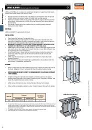
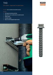
CHEMICAL ANCHOR PLUS<br />
Polyester anchoring system for secure fixing<br />
into non-cracked concrete.<br />
Function: After drilling <strong>and</strong> cleaning the hole, the capsule is inserted into<br />
the hole <strong>and</strong> the anchor stud is driven with a rotating/hammering action.<br />
This breaks the capsule <strong>and</strong> mixes the contents. The resulting chemical<br />
reaction creates a durable expansion pressure free bond between the<br />
anchor stud, the reacted resin, <strong>and</strong> the concrete.<br />
Benefits:<br />
• Expansion pressure free<br />
• Reduced permissible edge distances <strong>and</strong> spacings<br />
• Completely seals drilled hole<br />
22
Adhesive Systems<br />
CHEMICAL ANCHOR PLUS<br />
CONSTRUCTION:<br />
KLS Threaded stud<br />
KLP Capsule<br />
Setting tool<br />
C-ANCHORS-2013 © SIMPSON STRONG-TIE ®<br />
MATERIAL:<br />
KLS: Carbon steel, zinc plated <strong>and</strong> blue passivated<br />
KLS A4: A4-70 stainless steel<br />
KLP: Glass capsule with polyester resin, hardener <strong>and</strong> mineral aggregates<br />
BASE MATERIAL:<br />
Non-cracked concrete C20/25 to C50/60 (B25 to B55)<br />
LOAD RANGE:<br />
Tension:<br />
Shear:<br />
TEMPERATURE RANGE:<br />
N perm<br />
= 4.0 - 60.0 [kN]<br />
V perm<br />
= 4.0 - 60.0 [kN]<br />
Maximum long-term service temperature = +50°C; Maximum short-term service temperature = +80 °C<br />
RANGE SUPPLIED:<br />
KLS: M8 – M30, carbon steel, zinc plated <strong>and</strong> blue passivated / A4 stainless steel<br />
APPLICATIONS:<br />
Brackets<br />
Base plates<br />
Railings<br />
BENEFITS:<br />
Causes no expansion pressure<br />
Reduced edge distances <strong>and</strong> spacings<br />
High capacity in non-cracked concrete<br />
PRODUCT DESCRIPTION:<br />
Steel construction<br />
Storage racks<br />
Machines<br />
Stud with hex head for easy installation<br />
with setting tool<br />
Completely seals drilled hole<br />
The Chemical Anchor Plus adhesive fixing system consists of a threaded stud <strong>and</strong> chemical-filled<br />
glass capsule.<br />
During installation, the capsule is crushed <strong>and</strong> the rotating <strong>and</strong> hammering action mixes the contents.<br />
After the recommended cure time, the fixture can be installed <strong>and</strong> the fixing can be loaded.<br />
Capsule have shelf life of 2 years when stored correctly. Don’t use if capsule is damaged or if the<br />
contents do not flow in a honey-like fashion of room temperature.<br />
The bond strength between the cured chemical <strong>and</strong> the drilled hole is dependent on the thorough<br />
cleaning of the drilled hole. Follow the installation instructions carefully.<br />
STORAGE OF KLP:<br />
Dry, dark, at a temperature between +5°C <strong>and</strong> +25°C. Avoid direct sunlight.<br />
SHELF LIFE:<br />
18 months after manufacturing date when stored according to the above recommendations.<br />
Information from Koelner Stahl.<br />
INSTALLATION:<br />
Pre-fix installation shown<br />
90°<br />
Photo: Lödige<br />
Drill hole <strong>and</strong> thoroughly<br />
clean (brushing <strong>and</strong> blowing)<br />
Insert KLP capsule into<br />
drilled hole<br />
Spin in KLS stud to the<br />
em bedment depth marking<br />
using a rotary hammer drill<br />
After the specified cure time,<br />
install the fixture <strong>and</strong> apply<br />
the recommended fastening<br />
torque with a calibrated<br />
torque-wrench<br />
23
Adhesive Systems<br />
CHEMICAL ANCHOR PLUS<br />
Carbon steel, zinc plated / A4 stainless steel<br />
KLS, CARBON STEEL, ZINC PLATED<br />
Threaded stud with hex head, hex nut <strong>and</strong> washer<br />
Material: Grade 5.8 steel, zinc plated <strong>and</strong> blue passivated<br />
Type<br />
Order Code<br />
Thread<br />
Size<br />
Ø x<br />
Depth of<br />
Drilled Hole<br />
Max.<br />
Fixture<br />
Thickness<br />
Ø Fixture<br />
Hole<br />
Eff.<br />
Embedment<br />
Depth<br />
Total<br />
Length<br />
Weight<br />
Box<br />
Quantity*<br />
Compatible<br />
Capsule<br />
d o x h 1 t fix d f h ef L<br />
[mm] [mm] [mm] [mm] [mm] [mm] [kg/100 pcs] [pcs] [Type]<br />
KLS 8/110 KLS0810080016 M8 10 x 80 16 9 80 110 4.0 10 KLP 8<br />
KLS 10/130 KLS1012090022 M10 12 x 90 22 12 90 130 9.0 10 KLP 10<br />
KLS 10/165 KLS1012090057 M10 12 x 90 57 12 90 165 10.6 10 KLP 10<br />
KLS 10/190 KLS1012090082 M10 12 x 90 82 12 90 190 11.7 10 KLP 10<br />
KLS 12/160 KLS1214110030 M12 14 x 110 30 14 110 160 14.5 10 KLP 12<br />
KLS 12/220 KLS1214110090 M12 14 x 110 90 14 110 220 18.6 10 KLP 12<br />
KLS 12/250 KLS1214110120 M12 14 x 110 120 14 110 250 20.7 10 KLP 12<br />
KLS 12/300 KLS1214110170 M12 14 x 110 170 14 110 300 24.1 10 KLP 12<br />
KLS 16/165 KLS1618125013 M16 18 x 125 13 18 125 165 26.0 10 KLP 16<br />
KLS 16/190 KLS1618125038 M16 18 x 125 38 18 125 190 29.0 10 KLP 16<br />
KLS 16/250 KLS1618125098 M16 18 x 125 98 18 125 250 36.3 10 KLP 16<br />
KLS 16/300 KLS1618125148 M16 18 x 125 148 18 125 300 42.3 10 KLP 16<br />
KLS 20/220 KLS2025170020 M20 25 x 170 20 22 170 220 50.1 6 KLP 20<br />
KLS 20/260 KLS2025170060 M20 25 x 170 60 22 170 260 58.0 6 KLP 20<br />
KLS 24/300 KLS2428210055 M24 28 x 210 55 26 210 300 98.5 6 KLP 24<br />
KLS 30/380 KLS3035280055 M30 35 x 280 55 33 280 380 196.0 4 KLP 30<br />
*Each box of KLS contains one setting tool.<br />
Custom lengths available on request.<br />
KLS, A4 STAINLESS STEEL<br />
Threaded stud with hex head, hex nut <strong>and</strong> washer<br />
Material: A4-70 stainless steel<br />
Type<br />
Order Code<br />
Thread<br />
Size<br />
Ø x<br />
Depth of<br />
Drilled Hole<br />
Max.<br />
Fixture<br />
Thickness<br />
Ø Fixture<br />
Hole<br />
Eff.<br />
Embedment<br />
Depth<br />
Total<br />
Length<br />
Weight<br />
Box<br />
Quantity*<br />
Compatible<br />
Capsule<br />
d o x h 1 t fix d f h ef L<br />
[mm] [mm] [mm] [mm] [mm] [mm] [kg/100 pcs] [pcs] [Type]<br />
KLS 8/110A4 KLS0810080016A4 M8 10 x 80 16 9 80 110 4.0 10 KLP 8<br />
KLS 10/130A4 KLS1012090022A4 M10 12 x 90 22 12 90 130 9.0 10 KLP 10<br />
KLS 10/165A4 KLS1012090057A4 M10 12 x 90 57 12 90 165 10.6 10 KLP 10<br />
KLS 10/190A4 KLS1012090082A4 M10 12 x 90 82 12 90 190 11.7 10 KLP 10<br />
KLS 12/160A4 KLS1214110030A4 M12 14 x 110 30 14 110 160 14.5 10 KLP 12<br />
KLS 12/220A4 KLS1214110090A4 M12 14 x 110 90 14 110 220 18.6 10 KLP 12<br />
KLS 12/250A4 KLS1214110120A4 M12 14 x 110 120 14 110 250 20.7 10 KLP 12<br />
KLS 12/300A4 KLS1214110170A4 M12 14 x 110 170 14 110 300 24.1 10 KLP 12<br />
KLS 16/165A4 KLS1618125013A4 M16 18 x 125 13 18 125 165 26.0 10 KLP 16<br />
KLS 16/190A4 KLS1618125038A4 M16 18 x 125 38 18 125 190 29.0 10 KLP 16<br />
KLS 16/250A4 KLS1618125098A4 M16 18 x 125 98 18 125 250 36.3 10 KLP 16<br />
KLS 16/300A4 KLS1618125148A4 M16 18 x 125 148 18 125 300 42.3 10 KLP 16<br />
KLS 20/220A4 KLS2025170020A4 M20 25 x 170 20 22 170 220 50.1 6 KLP 20<br />
KLS 20/260A4 KLS2025170060A4 M20 25 x 170 60 22 170 260 58.0 6 KLP 20<br />
KLS 24/300A4 KLS2428210055A4 M24 28 x 210 55 26 210 300 98.5 6 KLP 24<br />
KLS 30/380A4 KLS3035280055A4 M30 35 x 280 55 33 280 380 196.0 4 KLP 30<br />
*Each box of KLS contains one setting tool.<br />
Custom lengths available on request.<br />
KLP CAPSULE<br />
Glass capsule<br />
24<br />
Type<br />
Order Code<br />
Diameter Length Weight Box Quantity<br />
Ø<br />
L<br />
[mm] [mm] [kg/100 pcs] [pcs]<br />
KLP 8 KLP08 9 80 2.0 10<br />
KLP 10 KLP10 11 80 2.0 10<br />
KLP 12 KLP12 13 95 2.5 10<br />
KLP 16 KLP16 17 95 4.0 10<br />
KLP 20 KLP20 22 170 11.0 6<br />
KLP 24 KLP24 24 210 13.0 6<br />
KLP 30 KLP30 33 265 36.5 2
Adhesive Systems<br />
CHEMICAL ANCHOR PLUS TECHNICAL DATA<br />
Carbon steel, zinc plated / A4 stainless steel<br />
Permissible loads for single anchors without influence from edge <strong>and</strong> spacing distances.<br />
Material: Carbon steel, zinc plated <strong>and</strong> blue passivated; A4 stainless steel<br />
Thread size M8 M10 M12 M16 M20 M24 M30<br />
Effective embedment depth [mm] 80 90 110 125 170 210 280<br />
Type KLS... 8/... 10/... 12/... 16/... 20/... 24/... 30/...<br />
Permissible loads at any angle 1) Steel A4 Steel A4 Steel A4 Steel A4 Steel A4 Steel A4 Steel A4<br />
F perm<br />
Non-cracked concrete 2)<br />
C20/25 - C50/60<br />
[kN] 4.0 4.0 7.0 7.0 10.0 10.0 15.0 15.0 27.0 27.0 37.0 37.0 60.0 60.0<br />
Permissible bending moments<br />
M perm [Nm] 10.7 12.1 21.4 24.1 37.4 42.7 94.9 107.0 186.0 209.0 321.0 360.8 642.0 723.2<br />
Spacings, edge distances <strong>and</strong> member thicknesses<br />
Effective embedment depth h ef [mm] 80 80 90 90 110 110 125 125 170 170 210 210 280 280<br />
Characteristic spacing 3) a [mm] 200 200 220 220 270 270 310 310 420 420 520 520 700 700<br />
Minimum spacing a min [mm] 80 80 90 90 110 110 125 125 170 170 210 210 280 280<br />
Characteristic edge distance 3) a r [mm] 100 100 110 110 135 135 155 155 210 210 260 260 350 350<br />
Minimum edge distance a r,min [mm] 40 40 45 45 55 55 65 65 85 85 105 105 140 140<br />
Minimum member width b min [mm] 80 80 90 90 110 110 125 125 170 170 210 210 280 280<br />
Minimum member thickness h min [mm] 130 130 140 140 160 160 175 175 220 220 260 260 330 330<br />
Installation data<br />
Drill hole diameter d 0 [mm] 10 12 14 18 25 28 35<br />
Drill hole depth h 1 [mm] 80 90 110 125 170 210 280<br />
Clearance hole in the fixture d f [mm] 9 12 14 18 22 26 33<br />
Width across flats hex nut sw [mm] 13 17 19 24 30 36 46<br />
Installation torque T inst [Nm] 10 20 40 80 150 200 400<br />
Installed anchor<br />
L<br />
sw<br />
Tinst<br />
Curing schedule<br />
d0<br />
h 0 = hef<br />
t fix<br />
hmin<br />
df<br />
Drill hole temperature Curing time<br />
[°C]<br />
[min]<br />
> 20 10<br />
10 - 20 20<br />
0 - 10 60<br />
1) Permitted loads per anchor in non-cracked concrete of strength C20/25 to C50/60 (B25 to B55) for axial tension, shear, <strong>and</strong> oblique loads.<br />
2) <strong>Concrete</strong> is considered non-cracked when the tensile stress within the concrete σ L<br />
+ σ R<br />
≤ 0. In the absence of a detailed analysis σ R = 3 N/mm2 can be assumed (σ L<br />
equals the tensile stress within the<br />
concrete resulting from external loads, including forces on the anchor).<br />
3) If spacings or edge distances are smaller than the characteristic values, the permissible loads shall be reduced based on the Kappa method.<br />
Complete your designs more easily by downloading our anchor software from our home-page: www.simpson-liebig.com<br />
C-ANCHORS-2013 © SIMPSON STRONG-TIE ®<br />
Quick-Set Drive Unit<br />
Use this setting tool with a st<strong>and</strong>ard drill to provide problem-free setting of M8-M20 threaded studs with the Chemical Anchor Plus<br />
(KLP) system (see page 50). The Quick-Drive setting tool also has a hexagonal recess that allow it to set threaded studs with hex<br />
heads.<br />
Type BE<br />
Type Order Code Size<br />
Weight<br />
[kg/100 pcs]<br />
Quick-Set Drive Unit M8 BE08 M8 11<br />
Quick-Set Drive Unit M10 BE10 M10 14<br />
Quick-Set Drive Unit M12 BE12 M12 14<br />
Quick-Set Drive Unit M16 BE16 M16 20<br />
Quick-Set Drive Unit M20 BE20 M20 34<br />
25
ACCESSORIES<br />
Dispensing Tools<br />
Equipped with a comfortable h<strong>and</strong>le they release a perfectly adapted pressure during dispensing. We striclty<br />
control the quality of the steel rods. Their hexagonal form makes them keep their shape. The reinforced<br />
cradle has been designed for an optimal positioning of the cartridge. Its anti-corrosive steel coating makes<br />
it a solid tool. <strong>Simpson</strong> <strong>Strong</strong>-<strong>Tie</strong> ® has developed a line of professional manual applicator guns that are<br />
powerful, strong <strong>and</strong> pefectly matched to our products.<br />
Name Code Qty. Box Qty. Outer-box Cartridges<br />
Extrusion tool DT300 DT300 1 12 160/280/300 ml<br />
Extrusion tool DT380 DT380 1 6 380 ml<br />
Extrusion tool DT650 DT650 1 6 400/650 ml<br />
DT300<br />
DT380<br />
High quality steel rod<br />
Reinforced cradle<br />
DT650<br />
Adequate number of<br />
pressure<br />
Comfortable h<strong>and</strong>le<br />
Sleeves<br />
Sleeves are required for fixings in hollow bricks. Various sizes are available depending on the product to be<br />
fixed.<br />
Name Code Qty. Box Qty. Large Box Dimensions<br />
Sleeve SH 12x50 SH12050-RP10 10 160 12x50 mm<br />
Sleeve SH 16x85 SH16085-RP6 6 96 16x85 mm<br />
Sleeve SH 16x130 SH16130-RP6 6 96 16x130 mm<br />
Sleeve SH 20x85 SH20085-RP4 4 64 20x85 mm<br />
Sleeve SH<br />
Mixing Nozzles<br />
Always use the proper <strong>Simpson</strong> <strong>Strong</strong>-<strong>Tie</strong>® mixing nozzle. Always inject the resin starting from the bottom<br />
of the hole <strong>and</strong> withdrawing gradually as the hole is filled. Ensure that the mixing nozzle reaches the bottom<br />
of the hole before starting injection. Use extension tubing if needed.<br />
Name Code Qty. Box Qty. Large Box Products<br />
Mixing nozzle MN1 MN1-RP10 10 60 POLY-GP/AT-HP<br />
Mixing nozzle MN2 MN2 20 20 SET-XP<br />
Extension Tubes<br />
In case of deep embedments it may be necessary to extend the mixer by attaching an extension tubes which<br />
enables to reach the bottom of the hole.<br />
Name Code Qty. Box Qty. Large Box Notes<br />
Extension MNE MNE-RP10 10 130 <strong>For</strong> MN1<br />
MN1<br />
MN2<br />
MNE<br />
26
ACCESSORIES<br />
Dust Pump<br />
Dust pumps are «a must» for proper hole cleaning.<br />
Name Code Qty. Box Qty. Large Box Notes<br />
Dust pump PUMP 1 4 Solid blocks<br />
Brushes<br />
Wire brushes with nylon bristles are available in two diameters <strong>and</strong> lengths. Always brush holes to loosen<br />
dust as per the installation instructions.<br />
Name Code Qty. Box Qty. Large Box Notes<br />
Brushes BR BR17-30 1 15<br />
One pack =<br />
1 BR17 + 1 BR30<br />
(Solid/Hollow blocks)<br />
PUMP<br />
BR17<br />
BR30<br />
Rods<br />
LMAS - Zinc-plated steel Grade 5.8<br />
Reference<br />
Threaded<br />
Rod<br />
Total<br />
length<br />
(mm)<br />
L<br />
Max<br />
thickness<br />
of the item<br />
to be fixed<br />
(mm)<br />
t fix<br />
Max Ø of the<br />
hole for the<br />
item to fix<br />
(mm)<br />
d f<br />
Embedment<br />
depth (mm)<br />
h ef<br />
Ø x min drill<br />
depth (mm)<br />
d 0<br />
x h 1<br />
LMAS0810064020 M8 95 20 9 64 10 x 64 30<br />
LMAS1012080025 M10 120 25 12 80 12 x 80 30<br />
LMAS1012080060 M10 155 60 12 80 12 x 80 30<br />
LMAS1214096035 M12 150 35 14 96 14 x 96 30<br />
LMAS1214096070 M12 185 70 14 96 14 x 96 30<br />
LMAS1618128020 M16 170 20 18 128 18 x 128 10<br />
LMAS1618128050 M16 200 50 18 128 18 x 128 10<br />
LMAS2022160050 M20 240 50 22 160 22 x 160 5<br />
LMAS A4 - Stainless Steel A4-70<br />
Box<br />
Qty<br />
LMAS<br />
Reference<br />
Threaded<br />
Rod<br />
Total<br />
length<br />
(mm)<br />
L<br />
Max<br />
thickness<br />
of the item<br />
to be fixed<br />
(mm)<br />
t fix<br />
Max Ø of the<br />
hole for the<br />
item to fix<br />
(mm)<br />
d f<br />
Embedment<br />
depth (mm)<br />
h ef<br />
Ø x min drill<br />
depth (mm)<br />
d 0<br />
x h 1<br />
LMAS0810064020A4 M8 95 20 9 64 10 x 64 20<br />
LMAS1012080025A4 M10 120 25 12 80 12 x 80 20<br />
LMAS1012080060A4 M10 155 60 12 80 12 x 80 20<br />
LMAS1214096035A4 M12 150 35 14 96 14 x 96 20<br />
LMAS1214096070A4 M12 185 70 14 96 14 x 96 20<br />
LMAS1618128020A4 M16 170 20 18 128 18 x 128 10<br />
LMAS1618128050A4 M16 200 50 18 128 18 x 128 10<br />
LMAS2022160050A4 M20 240 50 22 160 22 x 160 5<br />
Metal Sieve SHM<br />
Steel sieve (cut to length required)<br />
Box<br />
Qty<br />
C-ANCHORS-2013 © SIMPSON STRONG-TIE ®<br />
Compatible<br />
LMAS<br />
Ø Sieve<br />
Sieve<br />
Length<br />
Ø x<br />
Depth of<br />
Drilled Hole<br />
Weight<br />
Box<br />
Quantity<br />
Type<br />
Order Code<br />
d 0<br />
[mm] [mm] [mm] [mm] [kg/100 pcs] [pc]<br />
SHM 16/1000* SHM161000 LMAS M10 + M12 16 1000 16 7.6 1<br />
*Not included in approval.<br />
Internally Threaded Sleeve IGH<br />
Steel internally threaded sleeve<br />
Ø x<br />
Compatible<br />
Sieve<br />
Ø Sieve<br />
Depth of Drilled Hole<br />
Box<br />
Weight<br />
Type<br />
Order Code LMAS<br />
Length<br />
Quantity<br />
d 0 x h 1<br />
[mm] [mm] [mm] [mm] [kg/100 pcs] [pcs]<br />
IGH M8x80* IGH08080 LMAS M8 12 80 14 x 90 3.5 12<br />
IGH M10x80* IGH10080 LMAS M10 14 80 16 x 90 4.8 12<br />
IGH M12x80* IGH12080 LMAS M12 16 80 18 x 90 5.6 12<br />
*Not included in approval.<br />
27
SIMPSON STRONG-TIE ®<br />
Winchester Road<br />
Cardinal Point<br />
Tamworth<br />
Staffordshire<br />
B78 3HG<br />
United Kingdom<br />
Tel: +44 1827 255 600<br />
Fax: +44 1827 255 616<br />
www.strongtie.co.uk<br />
Telephone: 01827 255600 | Visit: www.strongtie.co.uk