REVERSE OPG - A REVIVAL. C. Pravda, D. Koteeswaran. - Aosr.co.in
REVERSE OPG - A REVIVAL. C. Pravda, D. Koteeswaran. - Aosr.co.in
REVERSE OPG - A REVIVAL. C. Pravda, D. Koteeswaran. - Aosr.co.in

Create successful ePaper yourself
Turn your PDF publications into a flip-book with our unique Google optimized e-Paper software.
C. <strong>Pravda</strong> * , D. <strong>Koteeswaran</strong> †<br />
ABSTRACT<br />
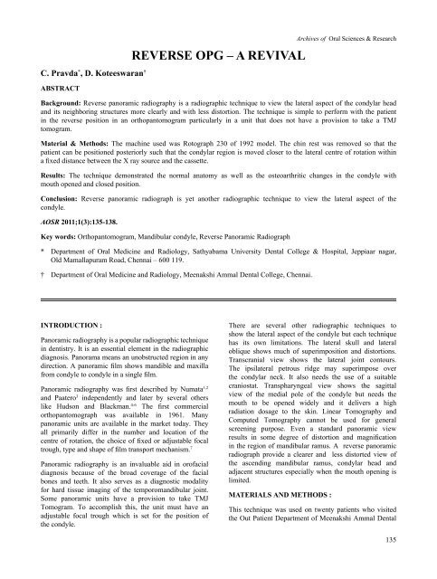
<strong>REVERSE</strong> <strong>OPG</strong> – A <strong>REVIVAL</strong><br />
Background: Reverse panoramic radiography is a radiographic technique to view the lateral aspect of the <strong>co</strong>ndylar head<br />
and its neighbor<strong>in</strong>g structures more clearly and with less distortion. The technique is simple to perform with the patient<br />
<strong>in</strong> the reverse position <strong>in</strong> an orthopantomogram particularly <strong>in</strong> a unit that does not have a provision to take a TMJ<br />
tomogram.<br />
Material & Methods: The mach<strong>in</strong>e used was Rotograph 230 of 1992 model. The ch<strong>in</strong> rest was removed so that the<br />
patient can be positioned posteriorly such that the <strong>co</strong>ndylar region is moved closer to the lateral centre of rotation with<strong>in</strong><br />
a fixed distance between the X ray source and the cassette.<br />
Results: The technique demonstrated the normal anatomy as well as the osteoarthritic changes <strong>in</strong> the <strong>co</strong>ndyle with<br />
mouth opened and closed position.<br />
Conclusion: Reverse panoramic radiograph is yet another radiographic technique to view the lateral aspect of the<br />
<strong>co</strong>ndyle.<br />
AOSR 2011;1(3):135-138.<br />
Key words: Orthopantomogram, Mandibular <strong>co</strong>ndyle, Reverse Panoramic Radiograph<br />
* Department of Oral Medic<strong>in</strong>e and Radiology, Sathyabama University Dental College & Hospital, Jeppiaar nagar,<br />
Old Mamallapuram Road, Chennai – 600 119.<br />
† Department of Oral Medic<strong>in</strong>e and Radiology, Meenakshi Ammal Dental College, Chennai.<br />
Archives of Oral Sciences & Research<br />
INTRODUCTION :<br />
Panoramic radiography is a popular radiographic technique<br />
<strong>in</strong> dentistry. It is an essential element <strong>in</strong> the radiographic<br />
diagnosis. Panorama means an unobstructed region <strong>in</strong> any<br />
direction. A panoramic film shows mandible and maxilla<br />
from <strong>co</strong>ndyle to <strong>co</strong>ndyle <strong>in</strong> a s<strong>in</strong>gle film.<br />
Panoramic radiography was first described by Numata 1,2<br />
and Paatero 3 <strong>in</strong>dependently and later by several others<br />
like Hudson and Blackman. 4-6 The first <strong>co</strong>mmercial<br />
orthopantomograph was available <strong>in</strong> 1961. Many<br />
panoramic units are available <strong>in</strong> the market today. They<br />
all primarily differ <strong>in</strong> the number and location of the<br />
centre of rotation, the choice of fixed or adjustable focal<br />
trough, type and shape of film transport mechanism. 7<br />
Panoramic radiography is an <strong>in</strong>valuable aid <strong>in</strong> orofacial<br />
diagnosis because of the broad <strong>co</strong>verage of the facial<br />
bones and teeth. It also serves as a diagnostic modality<br />
for hard tissue imag<strong>in</strong>g of the temporomandibular jo<strong>in</strong>t.<br />
Some panoramic units have a provision to take TMJ<br />
Tomogram. To ac<strong>co</strong>mplish this, the unit must have an<br />
adjustable focal trough which is set for the position of<br />
the <strong>co</strong>ndyle.<br />
There are several other radiographic techniques to<br />
show the lateral aspect of the <strong>co</strong>ndyle but each technique<br />
has its own limitations. The lateral skull and lateral<br />
oblique shows much of superimposition and distortions.<br />
Transcranial view shows the lateral jo<strong>in</strong>t <strong>co</strong>ntours.<br />
The ipsilateral petrous ridge may superimpose over<br />
the <strong>co</strong>ndylar neck. It also needs the use of a suitable<br />
craniostat. Transpharyngeal view shows the sagittal<br />
view of the medial pole of the <strong>co</strong>ndyle but needs the<br />
mouth to be opened widely and it delivers a high<br />
radiation dosage to the sk<strong>in</strong>. L<strong>in</strong>ear Tomography and<br />
Computed Tomography cannot be used for general<br />
screen<strong>in</strong>g purpose. Even a standard panoramic view<br />
results <strong>in</strong> some degree of distortion and magnification<br />
<strong>in</strong> the region of mandibular ramus. A reverse panoramic<br />
radiograph provide a clearer and less distorted view of<br />
the ascend<strong>in</strong>g mandibular ramus, <strong>co</strong>ndylar head and<br />
adjacent structures especially when the mouth open<strong>in</strong>g is<br />
limited.<br />
MATERIALS AND METHODS :<br />
This technique was used on twenty patients who visited<br />
the Out Patient Department of Meenakshi Ammal Dental<br />
135
C. <strong>Pravda</strong> et al.<br />
College, Chennai to demonstrate the normal anatomy<br />
as well as the osteoarthitic changes of the <strong>co</strong>ndyle. The<br />
mach<strong>in</strong>e that was used for the study was Rotograph<br />
230 of 1992 model. * Despite the advent of new<br />
technological advancement and <strong>in</strong>novation this unit<br />
is still <strong>in</strong> use to take <strong>OPG</strong>s and reverse <strong>OPG</strong>s. Certa<strong>in</strong><br />
modifications were made <strong>in</strong> the mach<strong>in</strong>e. The ch<strong>in</strong> rest<br />
was removed so that the patient can be positioned<br />
posteriorly such that the <strong>co</strong>ndylar region is moved<br />
closer to the lateral centre of rotation with<strong>in</strong> a fixed<br />
distance between the X ray source and the cassette. The<br />
procedure was expla<strong>in</strong>ed to the patients regard<strong>in</strong>g the<br />
movement of the tube around the patient’s head. Patient<br />
was asked to remove the eyeglasses, earr<strong>in</strong>gs, dentures,<br />
hairp<strong>in</strong>s, etc. Patient can sit or stand erectly <strong>in</strong> the mach<strong>in</strong>e<br />
<strong>in</strong> the reverse position (Figure 1). The head was aligned<br />
with the mid sagittal plane perpendicular to the floor.<br />
The ch<strong>in</strong> was slightly tilted down so that the Frankfort<br />
l<strong>in</strong>e is parallel to the floor. Lateral head stabilizers<br />
are used to ensure that the patient’s head is central.<br />
Exposure is made with both mouth opened and<br />
closed position. It should be remembered that if the<br />
left and right markers are built-<strong>in</strong> the cassette, they will<br />
be <strong>in</strong><strong>co</strong>rrect. So the film mark<strong>in</strong>g has to be altered.<br />
Figure 2a : Normal radiographic anatomy – Standard<br />
panoramic view.<br />
Figure 2b : Normal radiographic anatomy – reverse panoramic<br />
view.<br />
Figure 1 : Patient positioned <strong>in</strong> a reverse direction <strong>in</strong> the<br />
<strong>OPG</strong> mach<strong>in</strong>e. The unit is Rotograph 230 of 1992 model.<br />
RESULTS :<br />
Figure 3a : Position of the <strong>co</strong>ndyle <strong>in</strong> a reverse <strong>OPG</strong> –<br />
Mouth opened position<br />
This technique can demonstrate the normal anatomy as<br />
well as the osteoarthritic changes <strong>in</strong> the <strong>co</strong>ndyle with<br />
mouth opened and closed position. (Figure 2 and 3)<br />
DISCUSSION :<br />
Panoramic radiograph is a curved surface tomogram.<br />
It is based on the pr<strong>in</strong>ciple of reciprocal movement of<br />
an x ray source and an image receptor around a central<br />
plane while the patient rema<strong>in</strong>s stationary. This central<br />
plane of the object that is not blurred on the radiograph<br />
is called as the plane of acceptable detail or image<br />
layer.<br />
Figure 3b : Position of the <strong>co</strong>ndyle <strong>in</strong> a reverse <strong>OPG</strong> -<br />
Mouth closed position<br />
*<br />
Villa Sistemi Medicall Spa, Italy<br />
136
Reverse <strong>OPG</strong><br />
Patient position<strong>in</strong>g is critical and needs to be accurate<br />
such that <strong>co</strong>ndylar region is close to the lateral centre<br />
of rotation. The speed is reduced so that the image<br />
layer moves closer to the centre of rotation and<br />
be<strong>co</strong>mes th<strong>in</strong>ner result<strong>in</strong>g <strong>in</strong> a clearer and less distorted<br />
view. This view is used especially when the mouth<br />
open<strong>in</strong>g is limited.<br />
Errors <strong>in</strong> the technique mostly occur with improper<br />
position<strong>in</strong>g of the patient.<br />
Advantages<br />
- Shows the <strong>co</strong>ndyle and its neighbor<strong>in</strong>g structures<br />
with the ascend<strong>in</strong>g ramus that is usually overlapped<br />
by the soft tissue shadows <strong>in</strong> the <strong>OPG</strong><br />
- The technique is simple to perform. Retakes are<br />
possible. And quality <strong>co</strong>ntrol is easier to ma<strong>in</strong>ta<strong>in</strong>.<br />
- Requires m<strong>in</strong>imum <strong>co</strong>operation from the patient<br />
- It practically elim<strong>in</strong>ates problem <strong>in</strong> patient with<br />
trismus or un<strong>co</strong>operative patient<br />
Limitations<br />
- Reverse <strong>OPG</strong> is not without problems. Position<strong>in</strong>g<br />
of the patient is more critical than for the standard<br />
view.<br />
- It is believed that this view <strong>in</strong>creases the exposure<br />
to the eye. It is precautious to use lead eye shields.<br />
Direct measurement of the eye doses were made<br />
us<strong>in</strong>g thermolum<strong>in</strong>escent dosimeters mounted on<br />
a ‘Rando’ tissue equivalent skull phantom. † Dosimetric<br />
studies shows that with <strong>co</strong>rrect position<strong>in</strong>g of the<br />
patient the dose delivered appears on an average to<br />
be very similar <strong>in</strong> both standard and reverse<br />
technique and that there is no <strong>in</strong>crease when us<strong>in</strong>g<br />
the reverse method. (Table 1)<br />
Table 1 : Comparison of dosages <strong>in</strong> Standard and reverse positions us<strong>in</strong>g ‘Rando’ phantom<br />
Sites<br />
Reverse cGy<br />
Markus 8<br />
Standard cGy<br />
Williams 9<br />
Standard cGy<br />
Bartolotta 10 Standard cGy Wall 11<br />
Left eye 0.003 0.002 0.002 0.002<br />
Right eye O.003 0.002 0.002 0.002<br />
Left external TMJ 0.010 0.007<br />
Right External TMJ 0.007 0.006<br />
Left Mastoid 0.006 0.006<br />
Right mastoid 0.004 0.005<br />
Back neck 0.002 0.008 0.100 0.12<br />
Centre tongue 0.035 0.013 0.024 0.22<br />
CONCLUSION :<br />
Reverse panoramic radiograph is yet another radiographic<br />
technique to view the lateral aspect of the<br />
<strong>co</strong>ndyle especially <strong>in</strong> patients with limited mouth<br />
open<strong>in</strong>g and it can be taken with orthopantomographic<br />
units that do not have the provision to take a TMJ<br />
tomogram.<br />
REFERENCES :<br />
1. Numata H. Considerations of the parabolic radiography<br />
of the dental arch. J. Shimizu Stud 1933;10:13 ( <strong>in</strong><br />
Japanese).<br />
2. Numata H, A trial on the narrow beam radiography.<br />
J. Shimizu Stud 1934;12:6 (<strong>in</strong> Japanese).<br />
3. Paatero Y. V. A New radiographic method <strong>in</strong> dentistry.<br />
Svom Hammaslaak Toimi 1946; 87:37 (F<strong>in</strong>nish).<br />
4. Hudson D.C. Kumpala J. W. Dickson G. A panoramic<br />
X ray dental mach<strong>in</strong>e. U S Armed Forces Med J.<br />
1957;13:46.<br />
5. Blackman S. Panoramic tomography. Dental Pract<br />
1955;5:368.<br />
6. Blackman S. Rotational tomography of the face. Br J<br />
Radiol. 1960 Jul;33:408-418.<br />
7. Fromer, Stabulas – Savage, Radiology for Dental<br />
Professionals: 8th edition: 260, 264.<br />
†<br />
Alderson Research Laboratories, NY.<br />
137
C. <strong>Pravda</strong> et al.<br />
8. A.F.Markus, D.I. Poswillo, J. Semple. The Reverse<br />
panoral radiograph. Br Dent J. 1987;162(4):145-148.<br />
9. Williams F.R, Hudson F.R, Markus A. F. Rotational<br />
panoramic radiography – a <strong>co</strong>mparison of radiation<br />
doses <strong>in</strong> the standard and reverse positions ( unpublished<br />
data).<br />
10. Bartolla A, Calenda E, Calcichia A, Indov<strong>in</strong>a P.L. Dental<br />
orthopaantomography : survey of patient dose.<br />
Radiology 1983;146:821-823.<br />
11. Wall BF, Fisher ES, Paynter R, Hudson A, Bird PD.<br />
Doses to patients from pantomographic and <strong>co</strong>nventional<br />
dental radiography. Br J Radiol. 1979;52:727-<br />
734.<br />
Correspondence :<br />
Dr. C. <strong>Pravda</strong> M.D.S<br />
Reader<br />
Department of Oral Medic<strong>in</strong>e and Radiology, Sathyabama University Dental College & Hospital<br />
Jeppiaar nagar, Old Mamallapuram Road, Chennai – 600 119<br />
EMAIL: prabhakaranramachandran@yahoo.<strong>co</strong>.<strong>in</strong><br />
138