digital Mass Flow Meters and Controllers for Gases - Tablar ...
digital Mass Flow Meters and Controllers for Gases - Tablar ...
digital Mass Flow Meters and Controllers for Gases - Tablar ...

You also want an ePaper? Increase the reach of your titles
YUMPU automatically turns print PDFs into web optimized ePapers that Google loves.
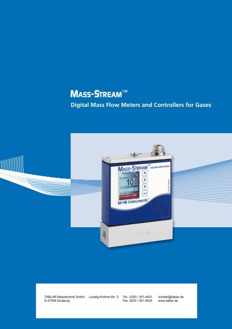
Digital <strong>Mass</strong> <strong>Flow</strong> <strong>Meters</strong> <strong>and</strong> <strong>Controllers</strong> <strong>for</strong> <strong>Gases</strong><br />
<br />
A subsidiary of Bronkhorst High-Tech.
M+W Instruments . Your specialists <strong>for</strong> inline measurement<br />
WORTH KNOWING<br />
M+W Instruments was founded in 1988 <strong>and</strong><br />
has always specialised in thermal mass flow<br />
meters <strong>and</strong> controllers <strong>for</strong> gases. Based on<br />
our long-lasting experience with the previous<br />
<strong>and</strong> well-established model series D-62xx<br />
our new series D-63xx works on the basis of<br />
direct through-flow measurement following<br />
the constant temperature anemometer<br />
principle.<br />
Having benefitted from continuous<br />
per<strong>for</strong>mance enhancements this through-<br />
flow technique can now be applied to lower<br />
flow ranges previously only covered by our<br />
by-pass technique (series D-51xx).<br />
Our instruments are suitable <strong>for</strong> use in the<br />
chemical <strong>and</strong> pharmaceutical industries, in<br />
mechanical engineering <strong>and</strong> semi-industrial<br />
applications, as well as in gas production,<br />
food <strong>and</strong> beverage industries. We are<br />
committed to a long lasting cooperation with<br />
our customers <strong>and</strong> of course we are also<br />
your competent contact <strong>for</strong> special solutions.<br />
You benefit from our well-trained, highly<br />
motivated team <strong>and</strong> our culture of quality.<br />
Our st<strong>and</strong>ardised product range guarantees<br />
short delivery times.<br />
Being a subsidiary of Bronkhorst High-Tech<br />
since 1997 we nowadays cooperate with<br />
more than 30 distributors worldwide. Please<br />
visit our website www.mw-instruments.com<br />
<strong>for</strong> the contact data of your local distributor.<br />
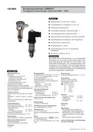
Principle of Through-<strong>Flow</strong> Measurement<br />
The mass flow meters <strong>and</strong> controllers consist<br />
of a metal body with a straight throughflow<br />
path. Two sensors are encased with stainless<br />
steel <strong>and</strong> protrude inside this bore; one is<br />
designed as a heater <strong>and</strong> the other one is<br />
designed as a temperature probe. A constant<br />
difference in temperature (ΔT) is created<br />
between the two sensors. The heater energy<br />
required to maintain this ΔT is dependent on<br />
the mass flow. The working principle is based<br />
on King’s law of the ratio between the mass<br />
flow <strong>and</strong> the heater energy. That means the<br />
higher the flow, the more energy is required<br />
to maintain the chosen ΔT.<br />
2
MASS-STREAM . Features <strong>and</strong> applications<br />
WORTH KNOWING<br />
For the thermal mass flow measurement<br />
of gases the new MASS-STREAM D-63xx<br />
series now offers the proven direct inline<br />
measurement <strong>for</strong> an increased measuring<br />
range:<br />
Smallest st<strong>and</strong>ard range<br />
0.01...0.2 ln/min (Air)<br />
Highest st<strong>and</strong>ard range<br />
100...5,000 ln/min (Air)<br />
Within the above mentioned borders<br />
intermediate calibrations with a turn-downratio<br />
up to 1:100 are also possible.<br />
In addition Bronkhorst High-Tech supplies<br />
instruments with smaller <strong>and</strong> higher<br />
flow ranges.<br />
Features<br />
Applications<br />
» Direct inline measurement principle<br />
» Measurement <strong>and</strong> control technology<br />
» Usable <strong>for</strong> virtually every kind of gas » Analytical instruments<br />
or gas-mix<br />
» Biogas applications<br />
» <strong>Mass</strong> flow measurement <strong>and</strong> control <strong>for</strong> » Burner controls<br />
a wide scope of applications<br />
» Coating plants<br />
» Digital pc-board with additional interfaces » Exhaust gas measurement<br />
<strong>for</strong> <strong>Flow</strong>-Bus, DeviceNet, Profibus-DP ® , » Gas consumption measurement<br />
ModBus-RTU<br />
» Gas monitoring systems<br />
» Precise control mode <strong>and</strong> good<br />
» Mechanical engineering<br />
response times<br />
» N 2<br />
/O 2<br />
-generators<br />
» Compact <strong>and</strong> robust design<br />
» Paint-spray lines<br />
» IP65 <strong>for</strong> full product range<br />
» <strong>and</strong> much more<br />
» Bodies available in aluminium <strong>and</strong> stainless<br />
steel (AISI 316) <strong>for</strong> corrosive gases<br />
» Sensor made of stainless steel<br />
» Less sensitive to dirt <strong>and</strong> humidity<br />
» No inlet pipe required<br />
» Measurement without moving parts<br />
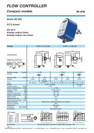
» Modern multi-coloured TFT display<br />
« IP65 compliant<br />
« Operator buttons on the instrument<br />
« Customised adjustable multi-functional display:<br />
actual flow, totaliser with memory <strong>and</strong> reset,<br />
alarm, setup <strong>and</strong> much more<br />
3
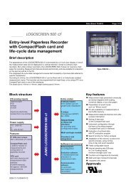
<strong>Mass</strong> flow meter (MFM) . D-63x0<br />
<strong>Mass</strong> flow controller (MFC) . D-63x1, D-63x3<br />
Principle of operation<br />
The <strong>digital</strong> MASS-STREAM mass flow meters <strong>and</strong> controllers are operated<br />
with a main-board with all functions <strong>for</strong> the flow measurement <strong>and</strong><br />
control. The instruments can be supplied with commonly used <strong>digital</strong> or<br />
analogue input/output signals <strong>and</strong> when ordering a <strong>digital</strong> instrument<br />
please <strong>for</strong>ward the required presettings. Along with the st<strong>and</strong>ard RS 232<br />
interface the additional interfaces Profibus-DP ® , DeviceNet, <strong>Flow</strong>-Bus<br />
<strong>and</strong> ModBus-RTU are also available.<br />
The <strong>digital</strong> MASS-STREAM model series is characterised by a high<br />
degree of signal integrity <strong>and</strong>, as an option, up to 8 calibration curves<br />
of different gases can be memorised in the instrument.<br />
To provide adaptability <strong>and</strong> flexibility <strong>for</strong> a wide range of different<br />
process conditions our customers are offered the possibility to adjust,<br />
to optimise <strong>and</strong> to evaluate the parameters <strong>and</strong> control characteristics,<br />
even whilst on site. The referring software is a basic part of our scope<br />
of supply of <strong>digital</strong> mass flow meters <strong>and</strong> controllers, as well as<br />
the calibration certificate, the 8-pin DIN connector <strong>for</strong> the electrical<br />
connection <strong>and</strong> the software <strong>and</strong> documentation on CD.<br />
The MASS-STREAM mass flow controllers are delivered as compact<br />
control units up to flows of 1,000 ln/min Air-equivalent, with the<br />
modular constructed solenoid valve integrated onto the body. The<br />
following kv-values are available as a st<strong>and</strong>ard: 0.066; 0.17; 1.0.<br />
In addition the control of higher gas flows is possible by using<br />
separate valves with the following kv-values: 2.8; 3.4; 4.4.<br />
(Further special valves <strong>and</strong> combinations on request.)<br />
4
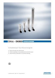
Dimensions M+W D-63xx series (in mm)<br />
Model A B C D E F G H I<br />
D-6310 95 G1/8“ G1/8“ 34 15 117<br />
D-6320 95 G1/8“ G1/8“ 34 15 117<br />
D-6340 95 G1/4“ G1/4“ 34 15 114<br />
D-6360 95 G1/2“ G1/2“ 34 16 122<br />
D-6370 117 G1/2“ G1/2“ 58 25 136 95<br />
D-6380 143 G1“ G1“ 83 37,5 164 95<br />
D-6311 95 G1/8“ G1/8“ 34 15 117<br />
D-6321 95 G1/8“ G1/8“ 34 15 117<br />
D-6341 95 G1/4“ G1/4“ 34 15 114<br />
D-6361 110 G1/2“ G1/2“ 34 16 122 95<br />
D-6371 185 G1/2“ G1/2“ 65 25 136 95 36 186<br />
Model D-6310 D-6320 D-6340 D-6360<br />
D-6311 D-6321 D-6341 D-6361<br />
Model D-6370 D-6380 Model D-6371<br />
D-6383 dimensions on request<br />
St<strong>and</strong>ard Measurement Ranges<br />
<strong>Mass</strong> flow meter<br />
<strong>Flow</strong> ranges (Air)<br />
<strong>Mass</strong> flow controller<br />
<strong>Flow</strong> ranges (Air)<br />
Model<br />
intermediate ranges are available<br />
Model<br />
intermediate ranges are available<br />
D - 6310 - H♦♦ - AA - ♦♦ - 22 - ♦ - S - D♦<br />
0.01...0.2 ln/min<br />
- 23 - 0.02...2.0 ln/min<br />
D - 6320 - H♦♦ - AA - ♦♦ - 13 - ♦ - S - D♦<br />
0.02...1.0 ln/min<br />
- 53 - 0.05...5.0 In/min<br />
D - 6340 - H♦♦ - BB - ♦♦ - 53 - ♦ - S - D♦<br />
0.1...5.0 ln/min<br />
- 54 - 0.5...50.0 ln/min<br />
D - 6360 - H♦♦ - CC - ♦♦ - 24 - ♦ - S - D♦<br />
0.4...20.0 ln/min<br />
- 25 - 2.0...200 ln/min<br />
D - 6370 - H♦♦ - CC - ♦♦ - 15 - ♦ - S - D♦<br />
2.0...100 ln/min<br />
- 16 - 10.0...1,000 ln/min<br />
D - 6380 - H♦♦ - DD - ♦♦ - 55 - ♦ - S - D♦<br />
10.0...500 ln/min<br />
- 56 - 50.0...5,000 ln/min<br />
D - 6311 - F♦♦ - AA - ♦♦ - 22 - ♦ - S - D ♦<br />
0.01...0.2 ln/min<br />
- 23 - 0.04...2.0 ln/min<br />
D - 6321 - F♦♦ - AA - ♦♦ - 13 - ♦ - S - D ♦<br />
0.02...1.0 ln/min<br />
- 53 - 0.1...5.0 ln/min<br />
D - 6341 - F♦♦ - BB - ♦♦ - 53 - ♦ - S - D ♦<br />
0.1...5.0 ln/min<br />
- 54 - 1.0...50.0 ln/min<br />
D - 6361 - F♦♦ - CC - ♦♦ - 24 - ♦ - S - D ♦<br />
0.4...20.0 ln/min<br />
- 25 - 4.0...200 ln/min<br />
D - 6371 - F♦♦ - CC - ♦♦ - 15 - ♦ - S - D ♦<br />
2.0...100 ln/min<br />
- 16 - 20.0...1,000 ln/min<br />
D - 6383 - Z♦♦ - DD - ♦♦ - 55 - ♦ - S - D ♦<br />
10.0...500 ln/min<br />
- 56 - 100...5,000 ln/min<br />
Technical changes <strong>and</strong> alterations in construction are reserved.<br />
5
MASS-STREAM . Worth knowing<br />
Conversion factor<br />
MASS-STREAM mass flow meters <strong>and</strong><br />
controllers are basically calibrated on air.<br />
If other gases or gas mixtures are used<br />
a conversion factor CF has to be applied.<br />
This factor is determined by applying a<br />
complex <strong>for</strong>mula. For a number of<br />
commonly used gases you will find<br />
the value in the adjoining chart.<br />
Conversion factorS (ln ≙ 1013 mbar <strong>and</strong> 0 °C air temperature)<br />
– please refer to www.fluidat.com<br />
Gas<br />
CF D-631x<br />
<strong>and</strong> D-632x<br />
CF D-634x<br />
up to D-638x<br />
Gas<br />
CF D-631x<br />
<strong>and</strong> D-632x<br />
Air 1.00 1.00 CO 2<br />
0.86 1.15<br />
Ar 1.50 2.02 HCl 1.12 1.54<br />
CH 4<br />
0.77 0.62 N 2<br />
1.00 1.00<br />
C 2<br />
H 2<br />
0.66 0.69 NH 3<br />
0.82 0.75<br />
C 2<br />
H 4<br />
0.70 0.77 NO 1.00 1.01<br />
C 2<br />
H 6<br />
0.58 0.63 N 2<br />
O 0.83 1.10<br />
C 3<br />
H 8<br />
0.43 0.53 O 2<br />
0.99 0.97<br />
C 4<br />
H 10<br />
0.32 0.42 Xe 1.96 6.10<br />
CF D-634x<br />
up to D-638x<br />
CO 1.01 1.04 Other gases on request.<br />
Above mentioned values are only regarded<br />
as an indication. The exact conversion factors<br />
are significantly dependent on the process<br />
parameters, like media temperature <strong>and</strong><br />
operating pressure, <strong>and</strong> on the physical<br />
characteristics of the gas. The best accuracy<br />
can be obtained by calibrating the instrument<br />
under operating conditions. The conversion<br />
factor causes an additional error in the absolute<br />
accuracy. With a conversion factor >1 this<br />
error is 2 x CF (in % FS) <strong>and</strong> with a conversion<br />
factor
Model number identification . MASS-STREAM<br />
D<br />
N N N<br />
N<br />
♦ ♦ ♦<br />
♦ ♦<br />
♦ ♦<br />
Base model<br />
Function<br />
Design<br />
Input/Output<br />
signal<br />
Supply voltage<br />
Gas connection<br />
inlet/outlet<br />
Material<br />
Seals<br />
D-631 up to 2 ln/min<br />
D-632 up to 5 ln/min<br />
D-634 up to 50 ln/min<br />
D-636 up to 200 ln/min<br />
D-637 up to 1,000 ln/min<br />
D-638 up to 5,000 ln/min<br />
0 = Meter<br />
1 = Controller<br />
with<br />
integrated<br />
valve<br />
3 = Controller<br />
with external<br />
valve<br />
F = Controller N/C<br />
(Valve normally<br />
closed)<br />
H = Meter<br />
Z = individual<br />
A = 0-5 Vdc<br />
B = 0-10 Vdc<br />
F = 0-20 mA<br />
G = 4-20 mA<br />
D = 15-24 Vdc<br />
Internal thread<br />
AA = G1/8” (= 1/8” BSPP)<br />
BB = G1/4” (= 1/4” BSPP)<br />
CC = G1/2” (= 1/2” BSPP)<br />
DD = G1” (= 1” BSPP)<br />
Fittings<br />
11 = 1/8“ compression<br />
22 = 1/4“ compression<br />
33 = 6 mm compression<br />
44 = 12 mm compression<br />
55 = 1/2“ compression<br />
66 = 20 mm compression<br />
88 = 1/4“ VCR<br />
99 = individual<br />
A = Aluminium AL 50ST/51ST<br />
S = Stainless steel SS 316<br />
E = EPDM<br />
K = Kalrez ®<br />
V = Viton<br />
Z = individual<br />
Enquiry <strong>and</strong> Order In<strong>for</strong>mation<br />
In order to supply the correct instrument <strong>for</strong> your application please<br />
<strong>for</strong>ward the following data: type of gas, flow range, operating<br />
temperature <strong>and</strong> pressure (<strong>for</strong> controllers supply <strong>and</strong> back pressure),<br />
electrical connection, desired output signal, type of gas connections<br />
(fittings) <strong>and</strong> seals, analogue or <strong>digital</strong> presettings.<br />
Based on this in<strong>for</strong>mation the following calculations <strong>and</strong> checks will be<br />
carried out:<br />
» Conversion of the requested flow to the Air-equivalent flow (the<br />
requested flow is divided by the referred conversion factor).<br />
Technical Specifications<br />
Measurement system<br />
Accuracy (based on calibration with<br />
Air at 5 bar (a) <strong>and</strong> T = 20 °C)<br />
Repeatability<br />
Pressure sensitivity<br />
Temperature sensitivity<br />
Attitude sensitivity<br />
Control stability<br />
Leak integrity<br />
Response time sensor (98 %)<br />
Settling time (controller)<br />
RFI (radio frequency interference)<br />
± 2 % FS including non-linearity*<br />
± 1.5 % FS on request*<br />
< ± 0.2 % FS<br />
± 0.3 % / bar typical (Air)<br />
± 0.2 % RD / °C (Air)<br />
at 90° deviation from horizontal<br />
max. error 0,2 % at 1 bar typical N 2<br />
< 0.2 % FS typical<br />
< 2 x 10⁻⁸ mbar l/s He<br />
τ ≤ 2 seconds<br />
plus approx. 2 seconds<br />
according to CE<br />
* The calibration of instruments in the lower measurement range <strong>and</strong> <strong>for</strong> some gases<br />
could result in a reduced accuracy.<br />
Mechanical parts<br />
Sensor Stainless steel SS 316 (AISI 316L)<br />
Instrument body Aluminium AL 50ST/51ST (anodised) or stainless steel SS 316<br />
Sieves <strong>and</strong> rings Teflon or stainless steel SS 316<br />
Protection IP65 (with <strong>and</strong> without display)<br />
Operating limits<br />
Measuring range up to 1...100 % (1:100) <strong>for</strong> meters<br />
(turn-down-ratio) up to 1...50 % (1:50) <strong>for</strong> controllers<br />
Type of gases almost all gases, compatible with chosen materials<br />
Temperature 0...50 °C<br />
Pressure rating 0...10 bar (g) <strong>for</strong> instrument body in aluminium,<br />
0...20 bar (g) <strong>for</strong> instrument body in stainless steel SS 316,<br />
0...6 bar (g) <strong>for</strong> D-6361 mass flow controller<br />
Warm-up time 30 minutes <strong>for</strong> optimum accuracy<br />
within 30 seconds <strong>for</strong> accuracy ± 4 % FS
N N<br />
♦<br />
S<br />
D<br />
♦<br />
<strong>Flow</strong> rate <strong>for</strong> air<br />
Display<br />
St<strong>and</strong>ard<br />
sensor<br />
Communication<br />
22 = 0.2 ln/min<br />
52 = 0.5 ln/min<br />
13 = 1 ln/min<br />
23 = 2 ln/min<br />
53 = 5 ln/min<br />
14 = 10 ln/min<br />
24 = 20 ln/min<br />
54 = 50 ln/min<br />
15 = 100 ln/min<br />
25 = 200 ln/min<br />
45 = 400 ln/min<br />
55 = 500 ln/min<br />
16 = 1,000 ln/min<br />
26 = 2,000 ln/min<br />
36 = 3,000 ln/min<br />
46 = 4,000 ln/min<br />
56 = 5,000 ln/min<br />
99 = other gases/<br />
other flow rates<br />
0 = without<br />
display<br />
D = with display<br />
DR = RS 232<br />
DF = <strong>Flow</strong>-Bus<br />
DP = Profibus-DP ®<br />
DN = DeviceNet<br />
DM = Modbus-RTU<br />
» For mass flow controllers only:<br />
- Check if the differential pressure over the valve (ΔP) is<br />
within the allowed limits.<br />
- Check if the calculated kv-value is within the specification.<br />
Electrical properties<br />
Supply voltage +15...24 Vdc ± 10 %<br />
Current peak values Meter approx. 75 mA at 0 % flow<br />
approx. 125 mA at 100 % flow<br />
Controller add 250 mA<br />
add 30 mA <strong>for</strong> display, if applicable<br />
add 50 mA <strong>for</strong> field bus, if applicable<br />
Output signal 0...10 Vdc / 0...5 Vdc active<br />
or 0...20 mA / 4...20 mA active<br />
Connector 8-pol round DIN (male) <strong>for</strong> analogue <strong>and</strong> RS 232<br />
additional conncetors <strong>for</strong> interfaces:<br />
» 5-pol M12 (male) <strong>for</strong> <strong>Flow</strong>-Bus<br />
DeviceNet<br />
Modbus-RTU<br />
» 5-pol M12 (female) <strong>for</strong> Profibus-DP ®<br />
Technical changes <strong>and</strong> alterations in construction are reserved.<br />
7