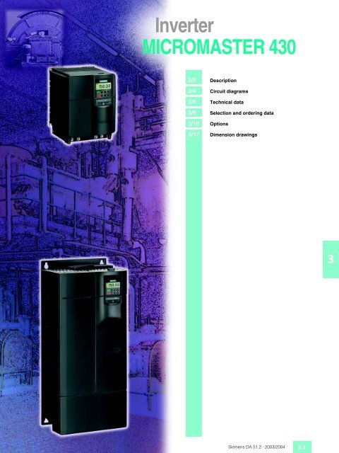
Inverter MICROMASTER 430
Inverter MICROMASTER 430
Inverter MICROMASTER 430

You also want an ePaper? Increase the reach of your titles
YUMPU automatically turns print PDFs into web optimized ePapers that Google loves.
<strong>Inverter</strong><br />
<strong>MICROMASTER</strong> <strong>430</strong><br />
3/2 Description<br />
3/4 Circuit diagrams<br />
3/6 Technical data<br />
3/9 Selection and ordering data<br />
3/10 Options<br />
3/17 Dimension drawings<br />
3<br />
Siemens DA 51.2 · 2003/2004 3/1
<strong>MICROMASTER</strong> <strong>430</strong><br />
Description<br />
3<br />
■ Applications ■ Main characteristics ■ Options (overview) ■ International standards<br />
The <strong>MICROMASTER</strong> <strong>430</strong> inverter<br />
is suitable for a variety<br />
of variable-speed drive applications.<br />
Its flexibility provides<br />
for a wide spectrum of applications.<br />
It is especially suitable<br />
for use with industrial<br />
pumps and fans. The inverter<br />
is especially characterized by<br />
its customer-oriented performance<br />
and ease-of-use. It has<br />
more inputs and outputs than<br />
the <strong>MICROMASTER</strong> 420, an<br />
optimized operator panel with<br />
manual/automatic switchover<br />
and adapted software functionality.<br />
■ Design<br />
The <strong>MICROMASTER</strong> <strong>430</strong> inverter<br />
has a modular design.<br />
The operator panels and communication<br />
modules can be<br />
easily exchanged.<br />
■ Easy, guided start-up<br />
■ Modular construction allows<br />
maximum configuration<br />
flexibility<br />
■ Six programmable isolated<br />
digital inputs<br />
■ Two scaleable analog inputs<br />
(0 V to 10 V, 0 mA to<br />
20 mA) can also be used as<br />
a 7th/8th digital input<br />
■ Two programmable analog<br />
outputs (0 mA to 20 mA)<br />
■ Three programmable relay<br />
outputs (30 V DC/5 A resistive<br />
load; 250 V AC/2A inductive<br />
load)<br />
■ Low-noise motor operation<br />
thanks to high pulse frequencies,<br />
adjustable (observe<br />
derating if necessary)<br />
■ Complete protection for<br />
motor and inverter<br />
■ Control of up to three additional<br />
drives on the basis of<br />
PID control (motor staging)<br />
■ Operation of drive directly<br />
on mains (with external bypass<br />
circuit)<br />
■ Low-energy mode<br />
■ Detects dry run of pumps<br />
(belt failure detection).<br />
■ Line commutating chokes<br />
■ Output chokes<br />
■ LC filter<br />
■ Gland plates<br />
■ Basic Operator Panel 2<br />
(BOP-2) for parameterizing<br />
the inverter<br />
■ Communication modules<br />
– PROFIBUS<br />
– DeviceNet<br />
–CANopen<br />
■ PC connection kits<br />
■ Mounting kits for installing<br />
the operator panels in the<br />
control cabinet doors<br />
■ PC start-up tools executable<br />
under Windows 95/98<br />
and NT/2000/<br />
XP Professional.<br />
■ TIA integration with<br />
Drive ES<br />
■ The <strong>MICROMASTER</strong> <strong>430</strong><br />
inverter complies with the<br />
requirements of the EU lowvoltage<br />
guideline<br />
■ The <strong>MICROMASTER</strong> <strong>430</strong><br />
inverter has the > marking<br />
■ acc. to u and cu certified<br />
■ c-tick ●✔<br />
Note:<br />
See Appendix for standards.<br />
3/2 Siemens DA 51.2 · 2003/2004
<strong>MICROMASTER</strong> <strong>430</strong><br />
■ Mechanical features ■ Performance features ■ Protection features<br />
■ Modular design<br />
■ Operating temperature<br />
–10 °C to +40 °C<br />
(+14 °F to +104 °F)<br />
■ Compact housing as a result<br />
of high power density<br />
■ Easy cable connection,<br />
mains and motor connections<br />
are separated for optimum<br />
electromagnetic compatibility<br />
■ Detachable operator<br />
panels<br />
■ Screwless control terminal<br />
strip on detachable I/O<br />
board.<br />
■ Latest IGBT technology<br />
■ Digital microprocessor<br />
control<br />
■ Flux Current Control (FCC)<br />
for improved dynamic response<br />
and optimized motor<br />
control<br />
■ Linear V/f characteristic<br />
■ Quadratic V/f characteristic<br />
■ Multipoint characteristic<br />
(programmable V/f characteristic)<br />
■ Flying restart<br />
■ Slip compensation<br />
■ Automatic restart following<br />
mains failure or fault<br />
■ Energy saving mode (stopping<br />
e.g. of a pump at low<br />
speeds)<br />
■ Motor staging (connection<br />
and disconnection of additional<br />
motors, use of inverter<br />
as control drive in a<br />
pump cascade)<br />
■ Manual/automatic mode<br />
■ Load torque monitoring<br />
(detects dry run of pumps)<br />
■ High-grade internal PID<br />
controller for simple process<br />
control<br />
■ Programmable acceleration/deceleration<br />
times<br />
from 0 s to 650 s<br />
■ Ramp smoothing<br />
■ Fast Current Limit (FCL) for<br />
trip-free operation<br />
■ Fast, repeatable digital input<br />
response time<br />
■ Fine adjustment using two<br />
high-resolution 10-bit analog<br />
inputs<br />
■ Compound braking for controlled<br />
rapid braking<br />
■ Four skip frequencies<br />
■ Removable “Y” capacitor for<br />
use on IT systems (with<br />
non-grounded mains supplies,<br />
the “Y” capacitor<br />
must be removed and an<br />
output choke installed).<br />
Description<br />
■ Overload capability<br />
7.5 kW to 90 kW:<br />
Overload current 1.4 x rated<br />
output current (i.e.<br />
+140 % overload capability)<br />
for 3 s, and 1.1 x rated<br />
output current (i.e. 110 %<br />
overload capability) for<br />
60 s, cycle time 300 s<br />
110 kW to 250 kW:<br />
Overload current 1.5 x rated<br />
output current (i.e.<br />
150 % overload capability)<br />
for 1 s, and 1.1 x rated output<br />
current (i.e. 110 % overload<br />
capability) for 59 s,<br />
cycle time 300 s<br />
■ Overvoltage/undervoltage<br />
protection<br />
■ <strong>Inverter</strong> overtemperature<br />
protection<br />
■ Special direct connection<br />
for PTC or KTY to protect<br />
the motor<br />
■ Earth fault protection<br />
■ Short-circuit protection<br />
■ I 2 t motor thermal protection<br />
■ Locked motor protection<br />
■ Stall prevention<br />
■ Parameter interlock<br />
3<br />
Siemens DA 51.2 · 2003/2004 3/3
<strong>MICROMASTER</strong> <strong>430</strong><br />
Circuit diagrams<br />
■ General circuit diagram<br />
F A H= J HF = A F JE <br />
! & J " & 8 ! ) +<br />
2 -<br />
5 <br />
" % 9<br />
) 1 <br />
) 1 <br />
<br />
!<br />
"<br />
8<br />
8<br />
)<br />
,<br />
* 2<br />
5 A HE= <br />
2 H J ? <br />
2 -<br />
!<br />
H= @ @ EJE = @ EC EJ= E F K JI<br />
, 1 % , 1 & A N JA H = <br />
? A ? JE I I D K @ > A = @ A <br />
<br />
<br />
) 1 <br />
) 1 <br />
<br />
<br />
)<br />
,<br />
, 1 %<br />
!<br />
"<br />
, 1 &<br />
<br />
<br />
, 1 <br />
3<br />
J H<br />
2 6 + 6 ;<br />
2 2<br />
H<br />
2 <br />
, 1<br />
, 1 !<br />
, 1 "<br />
, 1 #<br />
, 1 $<br />
2 6 + )<br />
2 6 + *<br />
#<br />
$<br />
%<br />
&<br />
$<br />
%<br />
'<br />
&<br />
"<br />
#<br />
)<br />
F J EI = JE <br />
K JF K J " 8 <br />
EI = JA @ <br />
K JF K J 8 <br />
EI = JA @ <br />
,<br />
+ 2 7<br />
) +<br />
, +<br />
JA I <br />
9 D A = = = C E F K JEI<br />
? BEC K HA @ = I = @ EC EJ= E F K J<br />
JD A JD HA I D @ L = K A I = HA = I<br />
B M I <br />
% # 8 , + BB<br />
! % 8 , + <br />
) 1 8 J 8 ) J )<br />
= @ 8 J 8<br />
) 1 8 J 8<br />
= @ ) J )<br />
) <br />
= N # 9<br />
) <br />
= N # 9<br />
K JF K JHA = O<br />
? J= ? JI<br />
# 8 ) + = N )<br />
E @ K ? JEL A = @ <br />
! 8 , + = N # )<br />
HA I EI JEL A = @ <br />
9 D A = ? K E? = JE I<br />
@ K A EI ? A ? JA @ <br />
JD A I A HE= E JA HB= ? A<br />
@ A I JM H <br />
) 7 6 <br />
) 7 6 <br />
) 7 6 <br />
) 7 6 <br />
4 +<br />
4 *<br />
4 )<br />
4 +<br />
4 *<br />
4 ! +<br />
4 ! *<br />
4 ! )<br />
2 <br />
<br />
<br />
!<br />
$<br />
%<br />
<br />
'<br />
&<br />
<br />
#<br />
"<br />
!<br />
'<br />
! <br />
) , ) # # " & ?<br />
)<br />
)<br />
,<br />
,<br />
4 5 " & #<br />
4 <br />
4 <br />
4 !<br />
$ 0 <br />
J<br />
K I A @<br />
# 0 <br />
<br />
, 12 5 M EJ? D A I<br />
+ JH * = H@ <br />
)<br />
) 1 ) 1<br />
8<br />
<br />
, 12 5 M EJ? D A I<br />
1 * = H@ <br />
, +<br />
2 -<br />
<br />
! <br />
) +<br />
7 8 9<br />
3/4 Siemens DA 51.2 · 2003/2004
<strong>MICROMASTER</strong> <strong>430</strong><br />
Circuit diagrams<br />
■ Terminal connection diagram<br />
Example, frame size C<br />
View A<br />
Mains connections<br />
Motor connections<br />
View A<br />
<br />
<br />
<br />
<br />
<br />
<br />
<br />
<br />
<br />
<br />
<br />
<br />
<br />
<br />
3<br />
<br />
<br />
<br />
<br />
<br />
<br />
<br />
<br />
<br />
<br />
<br />
<br />
<br />
<br />
<br />
<br />
<br />
<br />
<br />
<br />
Siemens DA 51.2 · 2003/2004 3/5
<strong>MICROMASTER</strong> <strong>430</strong><br />
Technical data<br />
■ <strong>MICROMASTER</strong> <strong>430</strong> inverter<br />
3<br />
Mains voltage and<br />
Power ranges<br />
Power frequency<br />
Output frequency<br />
7.5 kW to 90 kW<br />
110 kW to 250 kW<br />
3 AC 380 V to 480 V ± 10% 7.5 kW to 250 kW (variable torque)<br />
47 Hz to 63 Hz<br />
0 Hz to 650 Hz<br />
0 Hz to 267 Hz<br />
Power factor ˜ 0.95<br />
<strong>Inverter</strong> efficiency<br />
7.5 kW to 90 kW<br />
110 kW to 250 kW<br />
96 % to 97 %<br />
97 % to 98 %<br />
Overload capability 7.5 kW to 90 kW<br />
110 kW to 250 kW<br />
Overload current 1.4 x rated output current (i.e. +140 % overload capability) for 3 s, and<br />
1.1 x rated output current (i.e. 110 % overload capability) for 60 s, cycle time 300 s<br />
Overload current 1.5 x rated output current (i.e. 150 % overload capability) for 1 s and<br />
1.1 x rated output current (i.e. 110 % overload capability) for 60 s, cycle time 300 s<br />
Inrush current<br />
Less than rated input current<br />
Control method<br />
Linear V/f characteristic; quadratic V/f characteristic; multipoint characteristic<br />
(programmable V/f characteristic); flux current control (FCC), energy saving mode<br />
Pulse frequency 7.5 kW to 90 kW<br />
110 kW to 250 kW<br />
4 kHz (standard)<br />
2 kHz to 16 kHz (in 2 kHz steps)<br />
2 kHz (standard)<br />
2 kHz to 4 kHz (in 2 kHz steps)<br />
Fixed frequencies<br />
15, programmable<br />
Skip frequency ranges<br />
4, programmable<br />
Setpoint resolution<br />
0.01 Hz digital<br />
0.01 Hz serial<br />
10 bit analog<br />
Digital inputs<br />
6 fully programmable isolated digital inputs; switchable PNP/NPN<br />
Analog inputs<br />
2 programmable analog inputs<br />
• 0 V to 10 V, 0 mA to 20 mA and –10 V to +10 V (AIN1)<br />
• 0 V to 10 V and 0 mA to 20 mA (AIN2)<br />
• both can be used as 7th/8th digital input<br />
Relay outputs<br />
3, programmable, 30 V DC/5 A (resistive load); 250 V AC/2A (inductive load)<br />
Analog outputs<br />
2, programmable (0/4 mA to 20 mA)<br />
Serial interfaces<br />
RS-485, optional RS-232<br />
Motor cable length<br />
7.5 kW to 90 kW<br />
without output choke<br />
without output choke<br />
110 kW to 250 kW<br />
without output choke<br />
with output choke<br />
Electromagnetic compatibility<br />
7.5 kW to 90 kW<br />
For inverters without filter<br />
7.5 kW to 15 kW<br />
18.5 kW to 90 kW<br />
110 kW to 250 kW<br />
Braking<br />
Degree of protection<br />
Operating temperature range<br />
7.5 kW to 90 kW<br />
110 kW to 250 kW<br />
Storage temperature<br />
Relative humidity<br />
Installation altitude<br />
Protection features for<br />
7.5 kW to 90 kW<br />
110 kW to 250 kW<br />
Conformity with standards<br />
7.5 kW to 90 kW<br />
110 kW to 250 kW<br />
max. 50 m (shielded)<br />
max. 100 m (unshielded)<br />
see variant dependent options<br />
max. 100 m (shielded)<br />
max. 150 m (unshielded)<br />
Available soon<br />
<strong>Inverter</strong> with internal filter Class A available<br />
EMC filter, Class B to EN 55 011 available as an option<br />
EMC filter, Class B from Schaffner available as an option<br />
EMC filter, Class A available as an option<br />
DC braking, compound braking<br />
IP20<br />
–10 °C to +40 °C (+14 °F to +104 °F)<br />
0 °C to +40 °C (+32 °F to +104 °F)<br />
–40 °C to +70 °C (–40 °F to +158 °F)<br />
95 % (non-condensing)<br />
Up to 1000 m above sea level without derating<br />
Up to 2000 m above sea level without derating<br />
undervoltage, overvoltage, overload, earth faults, short-circuits, stall prevention, locked motor protection,<br />
motor overtemperature, inverter overtemperature, parameter change protection<br />
u, cu, >, c-tick ●✔<br />
u available soon, cu available soon, ><br />
> marking Conformity with low-voltage directive 73/23/EEC<br />
Dimensions and weights<br />
(without options)<br />
Frame size (FS)<br />
C<br />
D<br />
E<br />
F without filter<br />
F with filter<br />
FX<br />
GX<br />
H x W x D (mm)<br />
245 x 185 x 195<br />
520 x 275 x 245<br />
650 x 275 x 245<br />
850 x 350 x 320<br />
1150 x 350 x 320<br />
1400 x 326 x 356<br />
1533 x 326 x 545<br />
Weight, approx. (kg)<br />
5.7<br />
17<br />
22<br />
56<br />
75<br />
116<br />
176<br />
3/6 Siemens DA 51.2 · 2003/2004
<strong>MICROMASTER</strong> <strong>430</strong><br />
Technical data<br />
■ Derating data<br />
Pulse frequency<br />
Output<br />
(for 3 AC 400 V)<br />
Rated output current in A<br />
for a pulse frequency of<br />
kW 2 kHz 4 kHz 6 kHz 8 kHz 10 kHz 12 kHz 14 kHz 16 kHz<br />
7.5 19.0 19.0 17.1 15.2 13.3 11.4 9.5 7.6<br />
11.0 26.0 26.0 24.7 23.4 20.8 18.2 15.6 13.0<br />
15.0 32.0 32.0 28.8 25.6 22.4 19.2 16.0 12.8<br />
18.5 38.0 38.0 36.1 34.2 30.4 26.6 22.8 19.0<br />
22 45.0 45.0 40.5 36.0 31.5 27.0 22.5 18.0<br />
30 62.0 62.0 55.8 49.6 43.4 37.2 31.0 24.8<br />
37 75.0 75.0 71.3 67.5 60.0 52.5 45.0 37.5<br />
45 90.0 90.0 81.0 72.0 63.0 54.0 45.0 36.0<br />
55 110.0 110.0 93.5 77.0 63.3 49.5 41.3 33.0<br />
75 145.0 145.0 123.3 101.5 83.4 65.3 54.4 43.5<br />
90 178.0 178.0 138.0 97.9 84.6 71.2 62.3 53.4<br />
110 205.0 180.4 – – – – – –<br />
132 250.0 220.0 – – – – – –<br />
160 302.0 265.8 – – – – – –<br />
200 370.0 325.6 – – – – – –<br />
250 477.0 419.8 – – – – – –<br />
Operating temperature<br />
<strong>Inverter</strong> 7.5 kW to 90 kW<br />
G_DA51_EN_05045b<br />
<strong>Inverter</strong> 110 kW to 250 kW<br />
) , ) # # " % =<br />
Rated output current<br />
100<br />
%<br />
80<br />
60<br />
40<br />
20<br />
4 = JA @ K JF K J? K HHA J<br />
<br />
& #<br />
& <br />
<br />
$ <br />
" <br />
<br />
3<br />
0<br />
-10<br />
0 10 20 30 40 °C 50<br />
Operating temperature<br />
<br />
<br />
<br />
! " " # + # #<br />
F A H= JE C JA F A H= JK HA<br />
Siemens DA 51.2 · 2003/2004 3/7
<strong>MICROMASTER</strong> <strong>430</strong><br />
Technical data<br />
■ Derating data (continued)<br />
Installation height above sea level<br />
Permissible output current<br />
in % of the rated output current<br />
<strong>Inverter</strong> 7.5 kW to 90 kW<br />
Rated output current<br />
100<br />
%<br />
80<br />
60<br />
40<br />
20<br />
ADA51-5018c<br />
<strong>Inverter</strong> 110 kW to 250 kW<br />
<br />
<br />
<br />
<br />
<br />
<br />
<br />
<br />
<br />
0<br />
0 1000 2000 3000 m 4000<br />
Operational altitude<br />
<br />
<br />
<br />
<br />
<br />
3<br />
Permissible mains voltage<br />
in % of the max. possible mains voltage<br />
<strong>Inverter</strong> 7.5 kW to 90 kW<br />
Mains voltage<br />
100<br />
%<br />
80<br />
77<br />
60<br />
40<br />
20<br />
ADA51-5019b<br />
0<br />
0 1000 2000 3000 m 4000<br />
Operational altitude<br />
<strong>Inverter</strong> 110 kW to 250 kW<br />
Mains voltage<br />
100<br />
%<br />
80<br />
77<br />
ADA51-5019b<br />
60<br />
40<br />
20<br />
0<br />
0 1000 2000 3000 m 4000<br />
Operational altitude<br />
3/8 Siemens DA 51.2 · 2003/2004
<strong>MICROMASTER</strong> <strong>430</strong><br />
Selection and ordering data<br />
■ <strong>MICROMASTER</strong> <strong>430</strong> inverter<br />
Output<br />
Rated input<br />
current<br />
Rated output<br />
current<br />
kW hp A A (FS)<br />
Frame size<br />
Order No.<br />
<strong>MICROMASTER</strong> <strong>430</strong><br />
without filter 4 )<br />
<strong>MICROMASTER</strong> <strong>430</strong><br />
with internal filter<br />
Class A 3 )<br />
Mains operating voltage 3 AC 380 V to 480 V<br />
7.5 10 20.2 1 ) 19 C 6SE6<strong>430</strong>-2UD27-5CA0 6SE6<strong>430</strong>-2AD27-5CA0<br />
11.0 15 29.0 1 ) 26 C 6SE6<strong>430</strong>-2UD31-1CA0 6SE6<strong>430</strong>-2AD31-1CA0<br />
15.0 20 39.0 1 ) 32 C 6SE6<strong>430</strong>-2UD31-5CA0 6SE6<strong>430</strong>-2AD31-5CA0<br />
18.5 25 45.2 1 ) 38 D 6SE6<strong>430</strong>-2UD31-8DA0 6SE6<strong>430</strong>-2AD31-8DA0<br />
22 30 54.7 1 ) 45 D 6SE6<strong>430</strong>-2UD32-2DA0 6SE6<strong>430</strong>-2AD32-2DA0<br />
30 40 74.8 1 ) 62 D 6SE6<strong>430</strong>-2UD33-0DA0 6SE6<strong>430</strong>-2AD33-0DA0<br />
37 50 91.0 1 ) 75 E 6SE6<strong>430</strong>-2UD33-7EA0 6SE6<strong>430</strong>-2AD33-7EA0<br />
45 60 111.0 1 ) 90 E 6SE6<strong>430</strong>-2UD34-5EA0 6SE6<strong>430</strong>-2AD34-5EA0<br />
55 75 143.0 1 ) 110 F 6SE6<strong>430</strong>-2UD35-5FA0 6SE6<strong>430</strong>-2AD35-5FA0<br />
75 100 190.0 1 ) 145 F 6SE6<strong>430</strong>-2UD37-5FA0 6SE6<strong>430</strong>-2AD37-5FA0<br />
90 120 223.0 1 ) 178 F 6SE6<strong>430</strong>-2UD38-8FA0 6SE6<strong>430</strong>-2AD38-8FA0<br />
110 150 204.5 2 ) 205 FX 6SE6<strong>430</strong>-2UD41-1FA0 –<br />
132 200 244.5 2 ) 250 FX 6SE6<strong>430</strong>-2UD41-3FA0 –<br />
160 250 296.4 2 ) 302 GX 6SE6<strong>430</strong>-2UD41-6GA0 –<br />
200 300 354.0 2 ) 370 GX 6SE6<strong>430</strong>-2UD42-0GA0 –<br />
250 350 442.0 2 ) 477 GX 6SE6<strong>430</strong>-2UD42-5GA0 –<br />
See Appendix for note on ordering.<br />
All <strong>MICROMASTER</strong> <strong>430</strong> inverters<br />
are supplied with a Status<br />
Display Panel (SDP). A BOP-2<br />
or other options have to be<br />
ordered separately (see<br />
Pages 3/11 to 3/13).<br />
■ Motors for<br />
<strong>MICROMASTER</strong> <strong>430</strong><br />
Catalog M 11 contains selection<br />
and ordering data for motors<br />
which are particularly suitable<br />
for operation with the<br />
<strong>MICROMASTER</strong> <strong>430</strong> inverters<br />
(see Appendix for overview).<br />
This catalog is suitable for IEC<br />
motors. For motors according<br />
to US standards (NEMA)<br />
please refer to:<br />
http://www.sea.siemens.com/<br />
motors<br />
3<br />
1) Supplementary conditions:<br />
Input current at rated operating<br />
point, applicable at short-circuit<br />
voltage of the supply<br />
U SC = 1 % with reference to the<br />
inverter rated power and rated<br />
mains operating voltage of<br />
400 V without a line commutating<br />
choke.<br />
If a line commutating choke is<br />
used, the specified values at<br />
380 V to 480 V are reduced to<br />
between 70% and 80%<br />
2) Supplementary conditions:<br />
Input current at rated operating<br />
point, applicable at short-circuit<br />
voltage of the supply<br />
U SC $ 2.33 % with reference to<br />
the inverter rated power and<br />
rated mains voltage of 400 V.<br />
3) Use of <strong>MICROMASTER</strong> inverters<br />
with internal filter is not permissible<br />
on non-grounded<br />
mains supplies.<br />
4) Generally suited to heavy<br />
industrial applications. For<br />
details please refer to Appendix<br />
on page A/4.<br />
Siemens DA 51.2 · 2003/2004 3/9
<strong>MICROMASTER</strong> <strong>430</strong><br />
Options<br />
Variant dependent options<br />
■ Overview<br />
EMC filter, Class A<br />
All 7.5 kW to 90 kW inverters<br />
are supplied with an internal<br />
filter Class A.<br />
For inverters 110 kW to<br />
250 kW, EMC filters Class A<br />
are available. In this performance<br />
range, the EMC filters<br />
are only permitted to be used<br />
in combination with a line<br />
commutating choke.<br />
The requirements are fulfilled<br />
using shielded cables with a<br />
max. length of 25 m.<br />
3<br />
EMC filter, Class B<br />
Available for inverters 7.5 kW<br />
to 15 kW with an internal Class<br />
A EMC filter.<br />
The requirements are fulfilled<br />
using shielded cables with a<br />
max. length of 25 m.<br />
For inverters 18.5 kW to 90 kW<br />
without filters, EMC filters of<br />
Class B from Schaffner can be<br />
used.<br />
The requirements are fulfilled<br />
using shielded cables with a<br />
max. length of 25 m to 50 m<br />
(depending on the type, details<br />
on request).<br />
With this filter, the inverter<br />
complies with the emission<br />
standard EN 55 011, Class B.<br />
Leakage currents:<br />
The leakage currents of the inverters<br />
with/without filter (internal/external)<br />
may exceed<br />
30 mA. Typical values in practice<br />
are between 10 mA and<br />
50 mA. The exact values depend<br />
on the design, environment<br />
and cable lengths. Interference-free<br />
operation with<br />
residual current operated devices<br />
with a trigger value of<br />
30 mA cannot be guaranteed.<br />
However, operation with residual<br />
current operated devices<br />
with a trigger value of 300 mA<br />
is possible. Please refer to the<br />
Instruction Manual for details.<br />
LC filter<br />
The LC filter limits the rate of<br />
rise of voltage and the capacitive<br />
charge/discharge currents<br />
which usually occur with<br />
inverter operation. This means<br />
that much longer shielded motor<br />
cables are possible when<br />
using LC filters and the service<br />
life of the motor achieves<br />
values similar to those with direct<br />
mains operation.<br />
The LC filters can be used for<br />
all <strong>MICROMASTER</strong> <strong>430</strong> inverters<br />
of frame sizes C to F.<br />
•Frame size C:<br />
Only one footprint component<br />
is permissible for frame<br />
size C. If a line choke and LC<br />
filter are used, the line choke<br />
must be located on the left of<br />
the inverter. Required spacing:<br />
75 mm.<br />
• Frame sizes D to F:<br />
The LC filters, frame sizes D<br />
to F, are designed for<br />
mounting upright in the control<br />
cabinet. Due to leakage<br />
flux lines caused by physical<br />
sources, a minimum distance<br />
of 50 mm to adjacent<br />
modules and metal parts is<br />
recommended.<br />
Please note when using<br />
LC filters:<br />
•Only V/f, FCC control permissible<br />
• Increased inverter load: approx.<br />
10 % to 15 %<br />
• Operation only permissible<br />
with 4 kHz pulse frequency<br />
• The output frequency is limited<br />
to 150 Hz.<br />
Line commutating choke<br />
Line commutating chokes are<br />
used to smooth voltage peaks<br />
or to bridge commutating<br />
dips.<br />
In addition, line commutating<br />
chokes reduce the effects of<br />
harmonics on the inverter and<br />
the power supply. If the line<br />
impedance is < 1 %, a line<br />
commutating choke must be<br />
used in order to reduce the<br />
current peaks.<br />
No limits are currently defined<br />
in the EN 61 000-3-2 standard<br />
for professionally used devices<br />
with a connected load<br />
>1kW.<br />
This means that the inverters<br />
with an output power<br />
˜ 0.75 kW comply with the<br />
EN 61 000-3-2 standard.<br />
Output choke<br />
Output chokes can be supplied<br />
for reducing the capacitive<br />
compensation currents<br />
and dV/dt in the case of motor<br />
cables >50 m (shielded) or<br />
> 100 m (unshielded).<br />
For max. permissible cable<br />
lengths, see Technical Data.<br />
Gland plate<br />
Gland plates are available for<br />
inverters of frame size C. In<br />
frame sizes D, E and F, the<br />
gland plates are integrated.<br />
The gland plate facilitates the<br />
shield connection of power<br />
and control cables and thus<br />
ensure optimum EMC performance.<br />
3/10 Siemens DA 51.2 · 2003/2004
<strong>MICROMASTER</strong> <strong>430</strong><br />
Options<br />
Variant dependent options<br />
■ Technical data<br />
LC filter<br />
Mains voltage<br />
Current at (40 °C / 50 °C)<br />
For frame size C (7.5 to 15 kW)<br />
For frame size D (18.5 kW)<br />
For frame size D (22 kW)<br />
For frame size D (30 kW)<br />
For frame size E (37 kW)<br />
For frame size E (45 kW)<br />
For frame size F (55 kW)<br />
For frame size F (75 kW)<br />
For frame size F (90 kW)<br />
Limiting of motor overvoltage<br />
dV/dt limiting<br />
Pulse frequency<br />
Max. motor frequency<br />
Max. permissible motor cable lengths<br />
Shielded<br />
Unshielded<br />
3 AC 380 V to 480 V<br />
32.6 A/ 29.7 A<br />
38.8 A/ 32 A<br />
45.9 A/ 38 A<br />
63.2 A/ 45 A<br />
76.5 A/ 62 A<br />
112.2 A/ 90 A<br />
112.2 A/ 90 A<br />
147.9 A/110 A<br />
181.6 A/145 A<br />
ˆ 1078 V<br />
ˆ 500 V/ms<br />
4 kHz<br />
150 Hz<br />
200 m<br />
300 m<br />
Insulation strength Overvoltage category III to VDE 0110<br />
Electromagnetic compatibility<br />
Up to 200 m motor cable length with emissions to Class A according to EN 55 011 in conjunction<br />
with filtered inverters and unshielded cables<br />
Conformity<br />
CE according to the low-voltage directive 73/23/EEC<br />
Approvals<br />
UL available soon<br />
Strain resistance EN 60 068-2-31<br />
Humidity<br />
95 % humidity, non-condensing<br />
Degree of protection<br />
Frame size C<br />
Frame sizes D to F<br />
IP20 (to EN 60 529)<br />
IP00 / IP20 (to EN 60 529 with terminal covers)<br />
Insulation class<br />
H (180 °C)<br />
Temperature range<br />
Operation –10 °C to +40 °C (+14 °F to +104 °F) 100 % P n<br />
to +50 °C (to +122 °F)<br />
80 % P n<br />
Storage –25 °C to +70 °C (–13 °F to +158 °F)<br />
Installation altitude<br />
Frame size C Up to 2000 m: 100 % P n<br />
2000 to 4000 m: 62.5 % P n<br />
Frame sizes D to F to 1000 m:<br />
100 % P n<br />
1000 to 4000 m: 12.5 % derating for each 1000 m<br />
Mounting position<br />
Free space<br />
Connection system<br />
Torque for<br />
conductor connections<br />
Weight, approx.<br />
Input, litz wire or terminal<br />
Output, terminals<br />
Frame size C<br />
Frame sizes D to F<br />
for frame size C<br />
for frame size D<br />
for frame size E<br />
for frame size F<br />
Vertical<br />
100 mm<br />
100 mm<br />
100 mm<br />
1U1, 1V1, 1W1<br />
1U2, 1V2, 1W2<br />
Terminal cross-section Torque<br />
– 1.5 Nm to 1.8 Nm<br />
16 mm 2 2.0 Nm to 4.0 Nm<br />
35 mm 2 2.5 Nm to 5.0 Nm<br />
50 mm 2 3.0 Nm to 6.0 Nm<br />
95 mm 2 6.0 Nm to 12.0 Nm<br />
150 mm 2 10.0 Nm to 20.0 Nm<br />
29 kg<br />
21 kg to 34 kg<br />
49.5 kg to 67 kg<br />
67 kg to 77.5 kg<br />
3<br />
Max. permissible cable lengths from the motor to the inverter when using output chokes<br />
The following table shows the<br />
maximum permissible cable<br />
lengths from the motor to the<br />
inverter when using output<br />
chokes.<br />
Frame size Output choke Max. permissible motor cable lengths (shielded/unshielded)<br />
for a mains voltage of<br />
(FS) Type 380 V to 400 V ± 10 % 401 V to 480 V ± 10 %<br />
C 6SE6400-3TC03-2CD3 200 m/300 m 100 m/150 m<br />
D to F 6SE6400-3TC . . -. . D0 200 m/300 m 200 m/300 m<br />
FX/GX<br />
Available soon<br />
Siemens DA 51.2 · 2003/2004 3/11
<strong>MICROMASTER</strong> <strong>430</strong><br />
Options<br />
Variant dependent options<br />
■ Selection and ordering data<br />
The options listed here (filters,<br />
chokes, gland plates, fuses<br />
and circuit-breakers) must be<br />
selected to match the inverter.<br />
The inverter and the associated<br />
options have the same voltage<br />
ratings.<br />
All options are certified to<br />
u, except fuses.<br />
The 3NE1 fuses are u-listed<br />
(equivalent to U).<br />
l Use in America requires u-listed<br />
fuses such as the Class NON<br />
range from Bussmann.<br />
Mains voltage Output <strong>Inverter</strong><br />
Order No. of the options<br />
kW hp without filter<br />
EMC filter, Class A EMC filter, Class B LC filter<br />
3 AC 380 V to 480 V 7.5 10 6SE6<strong>430</strong>-2UD27-5CA0 – – 6SE6400-3TD03-2CD0<br />
11.0 15 6SE6<strong>430</strong>-2UD31-1CA0 – –<br />
15.0 20 6SE6<strong>430</strong>-2UD31-5CA0 – –<br />
18.5 25 6SE6<strong>430</strong>-2UD31-8DA0 – EMC filter, Class B, 6SE6400-3TD03-7DD0<br />
22 30 6SE6<strong>430</strong>-2UD32-2DA0 – available from Schaffner 6SE6400-3TD04-8DD0<br />
30 40 6SE6<strong>430</strong>-2UD33-0DA0 – 6SE6400-3TD06-1DD0<br />
37 50 6SE6<strong>430</strong>-2UD33-7EA0 – 6SE6400-3TD07-2ED0<br />
45 60 6SE6<strong>430</strong>-2UD34-5EA0 – 6SE6400-3TD11-5FD0<br />
55 75 6SE6<strong>430</strong>-2UD35-5FA0 –<br />
75 100 6SE6<strong>430</strong>-2UD37-5FA0 – 6SE6400-3TD15-0FD0<br />
90 120 6SE6<strong>430</strong>-2UD38-8FA0 – 6SE6400-3TD18-0FD0<br />
110 150 6SE6<strong>430</strong>-2UD41-1FA0 6SL3000-0BE32-5AA0 *) – Available soon<br />
132 200 6SE6<strong>430</strong>-2UD41-3FA0 6SL3000-0BE34-4AA0 *) –<br />
160 250 6SE6<strong>430</strong>-2UD41-6GA0 –<br />
*) Must be used in combination<br />
with a line 200 300 6SE6<strong>430</strong>-2UD42-0GA0 –<br />
commutating choke. 250 350 6SE6<strong>430</strong>-2UD42-5GA0 6SL3000-0BE36-0AA0 *) –<br />
3<br />
Mains voltage Output <strong>Inverter</strong><br />
Order No. of the options<br />
without filter<br />
Line commutating Output choke<br />
Gland plate<br />
kW hp<br />
choke<br />
3 AC 380 V to 480 V 7.5 10 6SE6<strong>430</strong>-2UD27-5CA0 6SE6400-3CC02-2CD3 6SE6400-3TC03-2CD3 6SE6400-0GP00-0CA0<br />
11.0 15 6SE6<strong>430</strong>-2UD31-1CA0<br />
15.0 20 6SE6<strong>430</strong>-2UD31-5CA0 6SE6400-3CC03-5CD3<br />
18.5 25 6SE6<strong>430</strong>-2UD31-8DA0 6SE6400-3CC04-4DD0 6SE6400-3TC05-4DD0 Integrated as standard<br />
22 30 6SE6<strong>430</strong>-2UD32-2DA0 6SE6400-3TC03-8DD0<br />
30 40 6SE6<strong>430</strong>-2UD33-0DA0 6SE6400-3CC05-2DD0 6SE6400-3TC05-4DD0<br />
37 50 6SE6<strong>430</strong>-2UD33-7EA0 6SE6400-3CC08-3ED0 6SE6400-3TC08-0ED0<br />
45 60 6SE6<strong>430</strong>-2UD34-5EA0 6SE6400-3TC07-5ED0<br />
55 75 6SE6<strong>430</strong>-2UD35-5FA0 6SE6400-3CC11-2FD0 6SE6400-3TC14-5FD0<br />
75 100 6SE6<strong>430</strong>-2UD37-5FA0 6SE6400-3TC15-4FD0<br />
90 120 6SE6<strong>430</strong>-2UD38-8FA0 6SE6400-3CC11-7FD0 6SE6400-3TC14-5FD0<br />
110 150 6SE6<strong>430</strong>-2UD41-1FA0 6SL3000-0CE32-3AA0 Available soon<br />
132 200 6SE6<strong>430</strong>-2UD41-3FA0 6SL3000-0CE32-8AA0<br />
160 250 6SE6<strong>430</strong>-2UD41-6GA0 6SL3000-0CE33-3AA0<br />
200 300 6SE6<strong>430</strong>-2UD42-0GA0 6SL3000-0CE35-1AA0<br />
250 350 6SE6<strong>430</strong>-2UD42-5GA0<br />
Mains voltage Output <strong>Inverter</strong><br />
without filter<br />
Order No. of the options<br />
Fuses (see Catalog LV 10)<br />
Circuit-breaker<br />
kW hp 3NA3 3NE1 (U) (see Catalog LV 10)<br />
3 AC 380 V to 480 V 7.5 10 6SE6<strong>430</strong>-2UD27-5CA0 3NA3807 l 3RV1031-4EA10<br />
11.0 15 6SE6<strong>430</strong>-2UD31-1CA0 3NA3812 3RV1031-4FA10<br />
15.0 20 6SE6<strong>430</strong>-2UD31-5CA0 3NA3814 3RV1031-4HA10<br />
18.5 25 6SE6<strong>430</strong>-2UD31-8DA0 3NA3820 3NE1817-0 3RV1042-4KA10<br />
22 30 6SE6<strong>430</strong>-2UD32-2DA0 3NA3822 3NE1818-0<br />
30 40 6SE6<strong>430</strong>-2UD33-0DA0 3NA3824 3NE1820-0 3RV1042-4MA10<br />
37 50 6SE6<strong>430</strong>-2UD33-7EA0 3NA3830 3NE1021-0 3VL1712- . DD33- . . . .<br />
45 60 6SE6<strong>430</strong>-2UD34-5EA0 3NA3832 3NE1022-0 3VL1716- . DD33- . . . .<br />
55 75 6SE6<strong>430</strong>-2UD35-5FA0 3NA3836 3NE1224-0 3VL3720- . DC36- . . . .<br />
75 100 6SE6<strong>430</strong>-2UD37-5FA0 3NA3140 3NE1225-0 3VL3725- . DC36- . . . .<br />
90 120 6SE6<strong>430</strong>-2UD38-8FA0 3NA3144 3NE1227-0 3VL4731- . DC36- . . . .<br />
110 150 6SE6<strong>430</strong>-2UD41-1FA0 – On request<br />
132 200 6SE6<strong>430</strong>-2UD41-3FA0 – 3NE1230-0<br />
160 250 6SE6<strong>430</strong>-2UD41-6GA0 – 3NE1332-0<br />
200 300 6SE6<strong>430</strong>-2UD42-0GA0 – 3NE1333-0<br />
250 350 6SE6<strong>430</strong>-2UD42-5GA0 – 3NE1435-0<br />
3/12 Siemens DA 51.2 · 2003/2004
<strong>MICROMASTER</strong> <strong>430</strong><br />
Options<br />
Variant dependent options<br />
■ Selection and ordering data (continued)<br />
Mains voltage Output <strong>Inverter</strong><br />
with internal filter<br />
kW hp Class A<br />
Order No. of the options<br />
LC filter<br />
Line commutating<br />
choke<br />
Output choke<br />
3 AC 380 V to 480 V 7.5 10 6SE6<strong>430</strong>-2AD27-5CA0 6SE6400-3TD03-2CD0 6SE6400-3CC02-2CD3 6SE6400-3TC03-2CD3<br />
11.0 15 6SE6<strong>430</strong>-2AD31-1CA0<br />
15.0 20 6SE6<strong>430</strong>-2AD31-5CA0 6SE6400-3CC03-5CD3<br />
18.5 25 6SE6<strong>430</strong>-2AD31-8DA0 6SE6400-3TD03-7DD0 6SE6400-3CC04-4DD0 6SE6400-3TC05-4DD0<br />
22 30 6SE6<strong>430</strong>-2AD32-2DA0 6SE6400-3TD04-8DD0 6SE6400-3TC03-8DD0<br />
30 40 6SE6<strong>430</strong>-2AD33-0DA0 6SE6400-3TD06-1DD0 6SE6400-3CC05-2DD0 6SE6400-3TC05-4DD0<br />
37 50 6SE6<strong>430</strong>-2AD33-7EA0 6SE6400-3TD07-2ED0 6SE6400-3CC08-3ED0 6SE6400-3TC08-0ED0<br />
45 60 6SE6<strong>430</strong>-2AD34-5EA0 6SE6400-3TD11-5FD0 6SE6400-3TC07-5ED0<br />
55 75 6SE6<strong>430</strong>-2AD35-5FA0 6SE6400-3CC11-2FD0 6SE6400-3TC14-5FD0<br />
75 100 6SE6<strong>430</strong>-2AD37-5FA0 6SE6400-3TD15-0FD0 6SE6400-3TC15-4FD0<br />
90 120 6SE6<strong>430</strong>-2AD38-8FA0 6SE6400-3TD18-0FD0 6SE6400-3CC11-7FD0 6SE6400-3TC14-5FD0<br />
Mains voltage Output <strong>Inverter</strong><br />
with internal filter<br />
Class A<br />
Order No. of the options<br />
Additional EMC filter,<br />
Class B<br />
Gland plate<br />
kW hp<br />
3 AC 380 V to 480 V 7.5 10 6SE6<strong>430</strong>-2AD27-5CA0 6SE6400-2FS03-8CD0 6SE6400-0GP00-0CA0<br />
11.0 15 6SE6<strong>430</strong>-2AD31-1CA0<br />
15.0 20 6SE6<strong>430</strong>-2AD31-5CA0<br />
18.5 25 6SE6<strong>430</strong>-2AD31-8DA0 An inverter without filter<br />
22 30 6SE6<strong>430</strong>-2AD32-2DA0<br />
30 40 6SE6<strong>430</strong>-2AD33-0DA0<br />
37 50 6SE6<strong>430</strong>-2AD33-7EA0<br />
45 60 6SE6<strong>430</strong>-2AD34-5EA0<br />
55 75 6SE6<strong>430</strong>-2AD35-5FA0<br />
75 100 6SE6<strong>430</strong>-2AD37-5FA0<br />
90 120 6SE6<strong>430</strong>-2AD38-8FA0<br />
must be selected to satisfy<br />
the EMC requirements<br />
of Class B. In<br />
addition, an appropriate<br />
EMC filter of Class B is<br />
from Schaffner is<br />
required.<br />
Integrated as standard<br />
3<br />
Mains voltage Output <strong>Inverter</strong> with internal filter<br />
Class A<br />
Order No. of the options<br />
Fuses (see Catalog LV 10)<br />
kW hp 3NA3 3NE1 (U)<br />
Circuit-breaker<br />
(see Catalog LV 10)<br />
3 AC 380 V to 480 V 7.5 10 6SE6<strong>430</strong>-2AD27-5CA0 3NA3807 l 3RV1031-4EA10<br />
11.0 15 6SE6<strong>430</strong>-2AD31-1CA0 3NA3812 3RV1031-4FA10<br />
15.0 20 6SE6<strong>430</strong>-2AD31-5CA0 3NA3814 3RV1031-4HA10<br />
18.5 25 6SE6<strong>430</strong>-2AD31-8DA0 3NA3820 3NE1817-0 3RV1042-4KA10<br />
22 30 6SE6<strong>430</strong>-2AD32-2DA0 3NA3822 3NE1818-0<br />
30 40 6SE6<strong>430</strong>-2AD33-0DA0 3NA3824 3NE1820-0 3RV1042-4MA10<br />
37 50 6SE6<strong>430</strong>-2AD33-7EA0 3NA3830 3NE1021-0 3VL1712- . DD33- . . . .<br />
45 60 6SE6<strong>430</strong>-2AD34-5EA0 3NA3832 3NE1022-0 3VL1716- . DD33- . . . .<br />
55 75 6SE6<strong>430</strong>-2AD35-5FA0 3NA3836 3NE1224-0 3VL3720- . DC36- . . . .<br />
75 100 6SE6<strong>430</strong>-2AD37-5FA0 3NA3140 3NE1225-0 3VL3725- . DC36- . . . .<br />
90 120 6SE6<strong>430</strong>-2AD38-8FA0 3NA3144 3NE1227-0 3VL4731- . DC36- . . . .<br />
l Use in America<br />
requires u-listed fuses<br />
such as the Class<br />
NON range from<br />
Bussmann.<br />
Siemens DA 51.2 · 2003/2004 3/13
<strong>MICROMASTER</strong> <strong>430</strong><br />
Options<br />
Variant independent options<br />
■ Overview<br />
Basic Operator Panel 2<br />
(BOP-2)<br />
With the BOP-2, individual parameter<br />
settings can be made.<br />
Values and units are shown on<br />
a 5-digit display.<br />
3<br />
Basic Operator Panel (BOP-2)<br />
A BOP-2 can be used for several<br />
inverters. It can be directly<br />
mounted on the inverter or in<br />
a control cabinet door using a<br />
mounting kit.<br />
PROFIBUS module<br />
For a complete PROFIBUS<br />
connection with up to<br />
ˆ12 Mbaud. Remote control<br />
of the inverter is possible with<br />
the PROFIBUS module. Remote<br />
control and operation at<br />
the inverter can be combined<br />
using an operator panel<br />
plugged onto the PROFIBUS<br />
module. The PROFIBUS module<br />
can be supplied by an external<br />
24 V DC power supply<br />
and is thus also active when<br />
the inverter is disconnected<br />
from the power supply.<br />
Connection by means of a<br />
9-pin Sub-D connector (available<br />
as an option).<br />
DeviceNet module<br />
For networking the inverters to<br />
the DeviceNet fieldbus system<br />
widely used on the American<br />
market. A maximum transmission<br />
rate of 500 kbaud is possible.<br />
Remote control of the inverter<br />
is possible with the<br />
DeviceNet module.<br />
Remote control and operation<br />
at the inverter can be combined<br />
using an operator panel<br />
plugged onto the DeviceNet<br />
module.<br />
The connection to the<br />
DeviceNet bus system is<br />
made using a 5-pin connector<br />
with terminal strip.<br />
CANopen module<br />
Using the CANopen communications<br />
module, an inverter<br />
can be linked to the CANopen<br />
fieldbus system and remote<br />
control is then possible.<br />
Remote control and operation<br />
at the inverter can be combined<br />
using an operator panel<br />
plugged onto the CANopen<br />
module.<br />
The module is connected to<br />
the bus system through a<br />
9-pin Sub-D connector.<br />
Connection kit for<br />
PC to inverter<br />
For controlling an inverter directly<br />
from a PC if the appropriate<br />
software has been installed<br />
(e.g. STARTER).<br />
Isolated RS-232 adapter module<br />
for reliable point-to-point<br />
connection to a PC. Includes a<br />
Sub-D connector and an<br />
RS-232 standard cable (3 m).<br />
Operator panel door mounting<br />
kit for single inverter<br />
For mounting an operator panel<br />
BOP-2 in a control cabinet<br />
door. Degree of protection<br />
IP56. Contains a cable adapter<br />
module with screwless terminals<br />
for use with user’s own<br />
RS-232 cables 1 ).<br />
Start-up tools<br />
•STARTER<br />
is a graphic start-up software<br />
for guided start-up for<br />
<strong>MICROMASTER</strong> 410/420/<br />
<strong>430</strong>/440 frequency inverters<br />
under Windows NT/2000/<br />
XP Professional. Parameter<br />
lists can be read out, altered,<br />
stored, entered and<br />
printed.<br />
• DriveMonitor<br />
is a start-up software for listoriented<br />
programming of<br />
frequency inverters. This<br />
program executes under<br />
Windows 95/98/NT/2000/<br />
XP Professional.<br />
Both programs are included<br />
on the Docu CD which is provided<br />
with every inverter.<br />
1) A shielded cable of type<br />
Belden 8132 (28 AWG) is<br />
recommended.<br />
The maximum cable length is<br />
5 m for RS-232.<br />
■ Selection and ordering data<br />
The options listed here are<br />
suitable for all<br />
<strong>MICROMASTER</strong> <strong>430</strong> inverters.<br />
Options<br />
Basic Operator Panel 2 (BOP-2)<br />
PROFIBUS module<br />
DeviceNet module<br />
CANopen module<br />
RS485/PROFIBUS bus connector<br />
Connection kit for PC to inverter<br />
Operator panel door mounting kit for single inverter<br />
Order No.<br />
6SE6400-0BE00-0AA0<br />
6SE6400-1PB00-0AA0<br />
6SE6400-1DN00-0AA0<br />
6SE6400-1CB00-0AA0<br />
6GK1500-0FC00<br />
6SE6400-1PC00-0AA0<br />
6SE6400-0PM00-0AA0<br />
3/14 Siemens DA 51.2 · 2003/2004
<strong>MICROMASTER</strong> <strong>430</strong><br />
Options<br />
Variant independent options<br />
■ Technical data of the communication modules<br />
PROFIBUS module<br />
6SE6400-1PB00-0AA0<br />
DeviceNet module<br />
6SE6400-1DN00-0AA0<br />
Size (height x width x depth)<br />
Degree of protection<br />
Degree of pollution<br />
Strain resistance<br />
• Stationary<br />
•Transport<br />
Deflection<br />
Acceleration<br />
Deflection<br />
Acceleration<br />
Climatic category (during operation) 3K3 to IEC 60 721-3-3<br />
Cooling method<br />
Natural air cooling<br />
Permissible ambient or cooling agent temperature<br />
• Operation<br />
• Storage and transport<br />
Relative humidity<br />
(permissible humidity rating)<br />
• Operation<br />
• Storage and transport<br />
Electromagnetic compatibility Emission<br />
Interference<br />
Power supply<br />
Output voltage<br />
161 mm x 73 mm x 46 mm<br />
IP20<br />
2 to IEC 60 664-1 (DIN VDE 0110/T1), no condensation permitted during operation<br />
to IEC 60 068-2-6 (if module is installed correctly)<br />
0.15 mm in the frequency range of 10 Hz to 58 Hz<br />
19.6 m/s 2 in the frequency range of 58 Hz to 500 Hz<br />
3.5 mm in the frequency range of 5 Hz to 9 Hz<br />
9.8 m/s 2 in the frequency range of 9 Hz to 500 Hz<br />
–10 °C to +50 °C (+14 °F to +122 °F)<br />
–25 °C to +70 °C (–13 °F to +158 °F)<br />
ˆ 85 % (non-condensing)<br />
ˆ 95 %<br />
to EN 55 011 (1991) Class A<br />
to IEC 60 801-3 and EN 61 000-4-3<br />
6.5 V ± 5 %, max. 300 mA,<br />
internal from inverter or<br />
24 V ± 10 %, max. 350 mA, external<br />
5 V ± 10 %, max. 100 mA,<br />
galvanically isolated supply<br />
• for terminating the serial interface bus or<br />
• for supplying the OLP (Optical Link Plug)<br />
6.5 V ± 5 %, max. 300 mA<br />
internal from inverter or<br />
24 V, max. 60 mA from DeviceNet-Bus<br />
Data transmission rate max. 12 Mbaud 125, 250 and 500 Kbaud<br />
–<br />
3<br />
Siemens DA 51.2 · 2003/2004 3/15
<strong>MICROMASTER</strong> <strong>430</strong><br />
Options<br />
Variant independent options<br />
■ Technical data of the communication modules (continued)<br />
CANopen module<br />
6SE6400-1CB00-0AA0<br />
3<br />
Size (height x width x depth)<br />
161 mm x 73 mm x 46 mm<br />
Degree of protection<br />
IP20<br />
Degree of pollution<br />
2 to IEC 60 664-1 (DIN VDE 0110/T1), no condensation permitted during operation<br />
Strain resistance<br />
• Stationary<br />
•Transport<br />
Deflection<br />
Acceleration<br />
Deflection<br />
Acceleration<br />
to IEC 60 068-2-6 (if module is installed correctly)<br />
0.15 mm in the frequency range of 10 Hz to 58 Hz<br />
19.6 m/s 2 in the frequency range of 58 Hz to 500 Hz<br />
3.5 mm in the frequency range of 5 Hz to 9 Hz<br />
9.8 m/s 2 in the frequency range of 9 Hz to 500 Hz<br />
Climatic category (during operation) 3K3 to IEC 60 721-3-3<br />
Cooling method<br />
Natural air cooling<br />
Permissible ambient or cooling agent temperature<br />
• Operation<br />
•Storage<br />
•Transport<br />
Relative humidity<br />
(permissible humidity rating)<br />
• Operation<br />
• Storage and transport<br />
Power supply<br />
Data transmission rate<br />
–10 °C to +50 °C (+14 °F to +122 °F)<br />
–40 °C to +70 °C (–40 °F to +158 °F)<br />
–25 °C to +70 °C (–13 °F to +158 °F)<br />
ˆ 85 % (non-condensing)<br />
ˆ 95 %<br />
The CAN bus is supplied from the inverter power supply<br />
10, 20, 50, 125, 250, 500, 800 Kbaud and 1 Mbaud<br />
Documentation<br />
■ Selection and ordering data<br />
Type of documentation Language Order No.<br />
Docu pack,<br />
supplied with each inverter,<br />
containing CD-ROM 1 ) and Getting<br />
Started Guide 2 )<br />
(paper version)<br />
Multilanguage<br />
6SE6400-5AE00-1AP0<br />
Operating instructions 2 )<br />
(paper version)<br />
Parameter list 2 )<br />
(paper version)<br />
German<br />
English<br />
French<br />
Italian<br />
Spanish<br />
German<br />
English<br />
French<br />
Italian<br />
Spanish<br />
6SE6400-5AE00-0AP0<br />
6SE6400-5AE00-0BP0<br />
6SE6400-5AE00-0DP0<br />
6SE6400-5AE00-0CP0<br />
6SE6400-5AE00-0EP0<br />
6SE6400-5AF00-0AP0<br />
6SE6400-5AF00-0BP0<br />
6SE6400-5AF00-0DP0<br />
6SE6400-5AF00-0CP0<br />
6SE6400-5AF00-0EP0<br />
1) The CD-ROM contains operating<br />
instructions, parameter list,<br />
commissioning tools STARTER<br />
and DriveMonitor, multilanguage<br />
2) Available on Internet at<br />
http://www.siemens.com/<br />
micromaster<br />
3/16 Siemens DA 51.2 · 2003/2004
<strong>MICROMASTER</strong> <strong>430</strong><br />
Dimension drawings<br />
■ <strong>MICROMASTER</strong> <strong>430</strong> inverter<br />
Frame size<br />
C<br />
D<br />
E<br />
3 AC 380 V to 480 V<br />
7.5 kW to 15 kW<br />
18.5 kW to 30 kW<br />
37 kW to 45 kW<br />
Drill pattern<br />
245 (9.65)<br />
ADA51-5002d<br />
204 (8.03)<br />
309 (12.16)<br />
ADA51-5009b<br />
174 (6.85)<br />
185 (7.28)<br />
<strong>Inverter</strong> frame size C<br />
195<br />
(7.68)<br />
Fixing with<br />
4 x M5 bolts<br />
4 x M5 nuts<br />
4 x M5 washers<br />
Tightening torque with washers fitted:<br />
3.0 Nm<br />
Ventilation clearance required at top<br />
and bottom: 100 mm<br />
<strong>Inverter</strong> frame size C<br />
with gland plate<br />
Drill pattern<br />
Drill pattern<br />
3<br />
ADA51-5020b<br />
520 (20.47)<br />
486 (19.13)<br />
650 (25.59)<br />
616.4 (24.27)<br />
275 (10.82)<br />
<strong>Inverter</strong> frame size D<br />
245<br />
(9.65)<br />
235 (9.25)<br />
Fixing with<br />
4 x M8 bolts<br />
4 x M8 nuts<br />
4 x M8 washers<br />
Tightening torque with<br />
washers fitted: 3.0 Nm<br />
Ventilation clearance<br />
required at top and bottom:<br />
300 mm<br />
ADA51-5021b<br />
275 (10.82)<br />
<strong>Inverter</strong> frame size E<br />
245<br />
(9.65)<br />
235 (9.25)<br />
Fixing with<br />
4 x M8 bolts<br />
4 x M8 nuts<br />
4 x M8 washers<br />
Tightening torque with<br />
washers fitted: 3.0 Nm<br />
Ventilation clearance<br />
required at top and bottom:<br />
300 mm<br />
With the communication module, the mounting depth increases<br />
for frame size C by 23 mm (0.91 inches).<br />
All dimensions in mm (values in brackets are in inches)<br />
Siemens DA 51.2 · 2003/2004 3/17
<strong>MICROMASTER</strong> <strong>430</strong><br />
Dimension drawings<br />
■ <strong>MICROMASTER</strong> <strong>430</strong> inverter<br />
Frame size<br />
F<br />
3 AC 380 V to 480 V<br />
55 kW to 90 kW<br />
Drill pattern<br />
Drill pattern<br />
850 (33.46)<br />
810 (31.89)<br />
1150 (45.28)<br />
1110 (43.70)<br />
3<br />
ADA51-5022b<br />
350 (13.78)<br />
320<br />
(12.6)<br />
<strong>Inverter</strong> frame size F without filter<br />
300 (11.81)<br />
Fixing with<br />
4 x M8 bolts<br />
4 x M8 nuts<br />
4 x M8 washers<br />
Tightening torque with<br />
washers fitted: 3.0 Nm<br />
Ventilation clearance<br />
required at top and bottom:<br />
350 mm<br />
ADA51-5023b<br />
350 (13.78)<br />
320<br />
(12.6)<br />
<strong>Inverter</strong> frame size F with filter<br />
300 (11.81)<br />
Fixing with<br />
4 x M8 bolts<br />
4 x M8 nuts<br />
4 x M8 washers<br />
Tightening torque with<br />
washers fitted: 3.0 Nm<br />
Ventilation clearance<br />
required at top and bottom:<br />
350 mm<br />
All dimensions in mm (values in brackets are in inches)<br />
3/18 Siemens DA 51.2 · 2003/2004
<strong>MICROMASTER</strong> <strong>430</strong><br />
Dimension drawings<br />
■ <strong>MICROMASTER</strong> <strong>430</strong> inverter<br />
Frame size<br />
FX<br />
GX<br />
3 AC 380 V to 480 V<br />
110 kW to 132 kW<br />
160 kW to 250 kW<br />
Drill pattern<br />
Drill pattern<br />
125 125<br />
(4.92) (4.92)<br />
125 125<br />
(4.92) (4.92)<br />
1400 (55.12)<br />
1375 (54.13)<br />
1533 (60.35)<br />
1508 (59.37)<br />
G_DA51_EN_05074<br />
326<br />
(12.83)<br />
356<br />
(14.06)<br />
<strong>Inverter</strong> frame size FX<br />
125<br />
(4.92) (4.92)<br />
125<br />
Fixing with<br />
6 x M8 bolts<br />
6 x M8 nuts<br />
6 x M8 washers<br />
Tightening torque<br />
with washers<br />
fitted: 13.0 Nm<br />
Ventilation clearance<br />
required:<br />
at top: 250 mm<br />
at bottom: 150 mm<br />
in front: 100 mm<br />
G_DA51_EN_05075<br />
326<br />
(12.83)<br />
545<br />
(21.46)<br />
<strong>Inverter</strong> frame size GX<br />
125<br />
(4.92) (4.92)<br />
125<br />
Fixing with<br />
6 x M8 bolts<br />
6 x M8 nuts<br />
6 x M8 washers<br />
Tightening torque<br />
with washers<br />
fitted: 13.0 Nm<br />
Ventilation clearance<br />
required:<br />
at top: 250 mm<br />
at bottom: 150 mm<br />
in front: 100 mm<br />
3<br />
All dimensions in mm (values in brackets are in inches)<br />
Siemens DA 51.2 · 2003/2004 3/19
<strong>MICROMASTER</strong> <strong>430</strong><br />
Dimension drawings<br />
■ EMC filter<br />
38<br />
(1.5)<br />
185 (7.28)<br />
156 (6.14)<br />
4 x M5<br />
245 (9.65)<br />
204 (8.03)<br />
ADA51-5012c<br />
219 (8.62)<br />
232 (9.13)<br />
174<br />
(6.85)<br />
54 (2.13)<br />
EMC filter for frame size C<br />
b 1<br />
c<br />
n 4<br />
b<br />
3<br />
G_DA51_XX_05103<br />
n 3<br />
a 1<br />
a<br />
EMC filter<br />
Class A<br />
Type<br />
6SL3000-<br />
for inverter Dimensions Weight,<br />
approx.<br />
Frame size<br />
(FS)<br />
a a 1 b b 1 c n 3 n 4 kg<br />
0BE32-5AA0 FX 270<br />
(10.63)<br />
0BE34-4AA0 FX/GX 270<br />
(10.63)<br />
0BE36-0AA0 GX 310<br />
(12.2)<br />
EMC filter for frame sizes FX and GX<br />
360<br />
(14.17)<br />
360<br />
(14.17)<br />
400<br />
(15.75)<br />
200<br />
(7.87)<br />
200<br />
(7.87)<br />
215<br />
(8.46)<br />
240<br />
(9.45)<br />
240<br />
(9.45)<br />
265<br />
(10.43)<br />
116<br />
(4.57)<br />
116<br />
(4.57)<br />
140<br />
(5.51)<br />
210<br />
(8.27)<br />
210<br />
(8.27)<br />
250<br />
(9.84)<br />
220<br />
(8.66)<br />
220<br />
(8.66)<br />
240<br />
(9.45)<br />
12.3<br />
12.3<br />
19.0<br />
All dimensions in mm (values in brackets are in inches)<br />
3/20 Siemens DA 51.2 · 2003/2004
<strong>MICROMASTER</strong> <strong>430</strong><br />
Dimension drawings<br />
■ LC filter<br />
140<br />
(5.51)<br />
185 (7.28)<br />
Drill pattern<br />
174 (6.85)<br />
320 (12.6)<br />
382 (15.04)<br />
335 (13.19)<br />
G_DA51_EN_05078a<br />
156 (6.14)<br />
G_DA51_EN_05081<br />
Fixing with M5 bolts<br />
LC filter 6SE6400-3TD03-2CD0 for frame size C<br />
a<br />
c<br />
b<br />
n 2<br />
n 1<br />
G_DA51_XX_05082<br />
LC filter<br />
Type<br />
for inverter<br />
Frame size<br />
(FS)<br />
Dimensions<br />
6SE6400-3TD03-7DD0 D 278<br />
(10.94)<br />
6SE6400-3TD04-8DD0 D 290<br />
(11.42)<br />
6SE6400-3TD06-1DD0 D 345<br />
(13.58)<br />
6SE6400-3TD07-2ED0 E 355<br />
(13.98)<br />
6SE6400-3TD11-5FD0 E/F 460<br />
(18.11)<br />
6SE6400-3TD15-0FD0 F 460<br />
(18.11)<br />
6SE6400-3TD18-0FD0 F 520<br />
(20.47)<br />
a b c n 1 n 2<br />
240 230 115<br />
(9.45) (9.06) (4.53)<br />
240<br />
(9.45)<br />
300<br />
(11.81)<br />
300<br />
(11.81)<br />
360<br />
(14.17)<br />
360<br />
(14.17)<br />
420<br />
(16.54)<br />
240<br />
(9.45)<br />
220<br />
(8.66)<br />
235<br />
(9.25)<br />
235<br />
(9.25)<br />
250<br />
(9.84)<br />
290<br />
(11.42)<br />
125<br />
(4.92)<br />
120<br />
(4.72)<br />
145<br />
(5.71)<br />
125<br />
(4.92)<br />
140<br />
(5.51)<br />
173<br />
(6.81)<br />
190<br />
(7.48)<br />
190<br />
(7.48)<br />
240<br />
(9.45)<br />
240<br />
(9.45)<br />
264<br />
(10.39)<br />
264<br />
(10.39)<br />
316<br />
(12.44)<br />
3<br />
Fixing with M10 bolts<br />
LC filter for frame sizes D to F<br />
All dimensions in mm (values in brackets are in inches)<br />
Siemens DA 51.2 · 2003/2004 3/21
<strong>MICROMASTER</strong> <strong>430</strong><br />
Dimension drawings<br />
■ Line commutating chokes<br />
c<br />
b<br />
c<br />
b<br />
a<br />
G_DA51_XX_05014e<br />
a<br />
DA51-5051<br />
Line commutating<br />
choke for<br />
Frame size C 245<br />
(9.65)<br />
Dimensions Weight<br />
(max.)<br />
a b c kg<br />
185<br />
(7.28)<br />
50<br />
(1.97)<br />
Line commutating choke for frame size C<br />
2.3<br />
Line commutating<br />
choke for<br />
Frame size D 520<br />
(20.47)<br />
Frame size E 650<br />
(25.59)<br />
Dimensions<br />
Weight<br />
(max.)<br />
a b c kg<br />
275<br />
(10.83)<br />
275<br />
(10.83)<br />
85<br />
(3.35)<br />
95<br />
(3.74)<br />
Line commutating choke for frame sizes D and E<br />
9.5<br />
17.0<br />
c<br />
b<br />
3<br />
a<br />
DA51-5052<br />
Line commutating<br />
choke<br />
type 6SE6400-<br />
for inverter Dimensions Weight<br />
(max.)<br />
Frame size a b c n 1 n 2 kg<br />
3CC11-.... F 210<br />
(8.27)<br />
240<br />
(9.45)<br />
141<br />
(5.55)<br />
109<br />
(4.29)<br />
190<br />
(7.48)<br />
25.0<br />
n 2<br />
n 1<br />
Line commutating choke for inverter frame size F<br />
c<br />
b<br />
a<br />
DA51-5053<br />
Line commutating<br />
choke<br />
type<br />
6SL3000-<br />
for inverter<br />
Frame size<br />
(FS)<br />
Dimensions<br />
0CE32-.... FX 248<br />
(9.76)<br />
0CE33-.... GX 248<br />
(9.76)<br />
0CE35-.... GX 269<br />
(10.59)<br />
Weight<br />
(max.)<br />
a b c n 1 n 2 kg<br />
255 203 101 200 24.0<br />
(10.04) (7.99) (3.98) (7.87)<br />
255<br />
(10.04)<br />
275<br />
(10.83)<br />
203<br />
(7.99)<br />
210<br />
(8.27)<br />
101<br />
(3.98)<br />
118<br />
(4.65)<br />
200<br />
(7.87)<br />
224<br />
(8.82)<br />
25.0<br />
35.0<br />
n 2<br />
n 1<br />
Line commutating choke for inverters of frame sizes FX and GX<br />
All dimensions in mm (values in brackets are in inches)<br />
3/22 Siemens DA 51.2 · 2003/2004
<strong>MICROMASTER</strong> <strong>430</strong><br />
Dimension drawings<br />
■ Output chokes<br />
c<br />
b<br />
a<br />
G_DA51_XX_05050a<br />
Output chokes for Dimensions Weight<br />
(max.)<br />
a b c kg<br />
Frame size C 245<br />
(9.65)<br />
185<br />
(7.28)<br />
80<br />
(3.15)<br />
5.6<br />
Line commutating choke<br />
for frame size C<br />
c<br />
b<br />
Output<br />
choke<br />
type<br />
6SE6400-<br />
for inverter Dimensions Weight<br />
(max.)<br />
Frame size a b c n 1 n 2 kg<br />
(FS)<br />
(to DIN 41308)<br />
a<br />
DA51-5052<br />
3TC03-8DD0 D 210<br />
(8.27)<br />
3TC05-4DD0 D 210<br />
(8.27)<br />
225<br />
(8.86)<br />
225<br />
(8.86)<br />
179<br />
(7.05)<br />
150<br />
(5.91)<br />
76<br />
(2.99)<br />
76<br />
(2.99)<br />
176<br />
(6.93)<br />
176<br />
(6.93)<br />
16.1<br />
10.7<br />
n 2<br />
n 1<br />
Output chokes<br />
for inverters of size D, E and F<br />
3TC07-5ED0 E 248<br />
(9.76)<br />
3TC08-0ED0 E 210<br />
(8.27)<br />
3TC14-5FD0 F 321<br />
(12.64)<br />
3TC15-4FD0 F 210<br />
(8.27)<br />
270<br />
(10.63)<br />
225<br />
(8.86)<br />
350<br />
(13.78)<br />
225<br />
(8.86)<br />
209<br />
(8.23)<br />
150<br />
(5.91)<br />
288<br />
(11.34)<br />
150<br />
(5.91)<br />
88<br />
(3.46)<br />
76<br />
(2.99)<br />
120<br />
(4.72)<br />
76<br />
(2.99)<br />
200<br />
(7.87)<br />
176<br />
(6.93)<br />
264<br />
(10.39)<br />
176<br />
(6.93)<br />
24.9<br />
10.4<br />
51.5<br />
11.2<br />
3<br />
All dimensions in mm (values in brackets are in inches)<br />
Siemens DA 51.2 · 2003/2004 3/23
<strong>MICROMASTER</strong> <strong>430</strong><br />
Dimension drawings<br />
■ Assembly of inverter and options<br />
G_DA51_XX_05042b<br />
Example:<br />
Assembly of<br />
inverter, filter and choke<br />
If additional options are<br />
required, they must be<br />
mounted on the side.<br />
3<br />
3/24 Siemens DA 51.2 · 2003/2004