Instruction Manual book - Pichler
Instruction Manual book - Pichler
Instruction Manual book - Pichler

You also want an ePaper? Increase the reach of your titles
YUMPU automatically turns print PDFs into web optimized ePapers that Google loves.
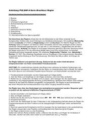
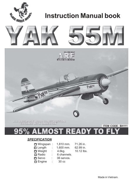
<strong>Instruction</strong> <strong>Manual</strong> <strong>book</strong><br />
ITEM CODE: BH111<br />
SPECIFICATION<br />
Wingspan : 1,810 mm. 71.26 in.<br />
Length : 1,600 mm. 62.99 in.<br />
Weight : 4.6kg. 10.12 lbs.<br />
Radio : 6 channels.<br />
Servo : 06 servos.<br />
Engine : 30 cc<br />
Made in Vietnam.
YAK 55 - ITEM CODE:BH111.<br />
<strong>Instruction</strong> <strong>Manual</strong><br />
This instruction manual is designed to help you build a great flying aeroplane. Please read this<br />
manual thoroughly before starting assembly of your YAK 55M. Use the parts listing below to identify<br />
all parts.<br />
WARNING.<br />
Please be aware that this aeroplane is not a toy and if assembled or used incorrectly it is<br />
capable of causing injury to people or property. WHEN YOU FLY THIS AEROPLANE YOU<br />
ASSUME ALL RISK & RESPONSIBILITY.<br />
If you are inexperienced with basic R/C flight we strongly recommend you contact your R/C supplier<br />
and join your local R/C Model Flying Club. R/C Model Flying Clubs offer a variety of training<br />
procedures designed to help the new pilot on his way to successful R/C flight. They will also be able<br />
to advise on any insurance and safety regulations that may apply.<br />
TOOLS & SUPPLIES NEEDED.<br />
<br />
<br />
<br />
<br />
<br />
<br />
<br />
<br />
<br />
<br />
<br />
<br />
<br />
<br />
<br />
Thick cyanoacrylate glue.<br />
30 minute epoxy.<br />
5 minute epoxy.<br />
Hand or electric drill.<br />
Assorted drill bits.<br />
Modelling knife.<br />
Straight edge ruler.<br />
2mm ball driver.<br />
Phillips head screwdriver.<br />
220 grit sandpaper.<br />
90° square or builder’s triangle.<br />
Wire cutters.<br />
Masking tape & T-pins.<br />
Thread-lock.<br />
Paper towels.<br />
PARTS LISTING.<br />
FUSELAGE ASSEMBLY<br />
(1) Fuselage.<br />
WING ASSEMBLY<br />
<br />
<br />
(1) Right wing half with pre-installed<br />
aileron.<br />
(1) Left wing half with pre-installed<br />
aileron.<br />
Tail section assembly<br />
<br />
<br />
(1) Vertical stabilizer with preinstalled<br />
rudder.<br />
(1) Horizontal stabilizer with preinstalled<br />
elevator halves.<br />
Some more parts.<br />
HARDWARE PACK<br />
COWLING.<br />
Landing gear.....<br />
SUGGESTION.<br />
To avoid scratching your new airplane, do not<br />
unwrap the pieces until they are needed for<br />
assembly. Cover your workbench with an old<br />
towel or brown paper, both to protect the aircraft<br />
and to protect the table. Keep a couple of<br />
jars or bowls handy to hold the small parts after<br />
you open the bag.<br />
NOTE.<br />
Please trial fit all the parts. Make sure you have<br />
the correct parts and that they fit and are<br />
aligned properly before gluing! This will assure<br />
proper assembly. YAK 55M ARF is hand made<br />
from natural materials, every plane is unique<br />
and minor adjustments may have to be made.<br />
However, you should find the fit superior and<br />
assembly simple.<br />
The painted and plastic parts used in this kit<br />
are fuel proof. However, they are not tolerant<br />
of many harsh chemicals including the following:<br />
paint thinner, C/A glue accelerator, C/A glue<br />
debonder and acetone. Do not let these chemicals<br />
come in contact with the colors on the<br />
covering and the plastic parts.<br />
2
YAK 55 - ITEM CODE:BH111.<br />
<strong>Instruction</strong> <strong>Manual</strong><br />
Caution: this model is not a toy!<br />
If you are a beginner to this type of powered<br />
model, please ask an experienced model flyer<br />
for help and support. If you attempt to operate<br />
the model without knowing what you are doing<br />
you could easily injure yourself or somebody<br />
else. Please keep your safety and well-being<br />
in mind at all times.<br />
Important: before you start construction<br />
Even if you have already built a large number<br />
of RC models please read right through these<br />
instructions and check all the kit components<br />
against the parts list. We have taken great<br />
trouble to keep construction as simple as<br />
possible, without making any compromises<br />
in the area of safety.<br />
Note regarding the film covering<br />
Minor creases or bubbles may develop in the<br />
film covering due to major fluctuations in<br />
weather conditions (temperature, humidity<br />
etc.); in rare cases you may even find a slight<br />
warp in a component. These minor faults are<br />
in the nature of film-covered built-up wooden<br />
structures, and can easily be corrected using<br />
a heat gun, as commonly used for modelling.<br />
Creases: Blow warm air over the area<br />
and rub down with a soft<br />
cloth.<br />
Wing warp: Hold the panel twisted<br />
gently in the opposite<br />
direction to the warp, and<br />
apply warm air to remove<br />
the creases from the<br />
covering.<br />
B.<br />
REPLACEMENT LARGE PARTS<br />
D.<br />
Caution! do not heat the film more than is<br />
absolutely necessary. If the air or the iron is<br />
too hot, the film may melt and holes may be<br />
formed.<br />
This model is highly pre-fabricated and can<br />
be built in a very short time. However, the work<br />
which you have to carry out is important and<br />
must be done carefully. The model will only<br />
be strong and fly well if you complete your<br />
tasks competently - so please work slowly and<br />
accurately.<br />
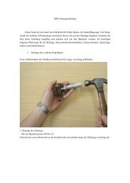
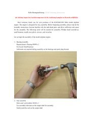
When self-tapping screws have to be<br />
screwed into wood, apply a little white glue<br />
to prevent them shaking loose: just squirt<br />
white glue into the hole and fit the screw.<br />
SAFETY PRECAUTION.<br />
+ This is not a toy<br />
+ Be sure that no other flyers are using your<br />
radio frequency.<br />
+The glow plug clip must be securely attached<br />
to the glow plug.<br />
+ Do not flip the propeller with your fingers.<br />
+ Keep loose clothing and wires away from<br />
the propeller.<br />
+ Do not start the motor if people are near.<br />
Do not stand in line with the side of the propeller.<br />
D.<br />
C.<br />
B.<br />
G.<br />
A.<br />
F.<br />
A. Cowling.<br />
B. Wing panel.<br />
C. Fuselage.<br />
D . Horizon stabilizer.<br />
F. Aluminium wing dihedral brace.<br />
G. Decal sheet.<br />
3
YAK 55 - ITEM CODE:BH111.<br />
<strong>Instruction</strong> <strong>Manual</strong><br />
REPLACEMENT SMALL PARTS<br />
1.<br />
4.<br />
2.<br />
3.<br />
6.<br />
5.<br />
1. Aluminium landing gear.<br />
2. Wheels.<br />
3. Fuel Tank.<br />
INSTALLING THE AILERON SERVOS.<br />
1. Install the rubber grommets and brass<br />
eyelets onto the aileron servo.<br />
4. Spinner.<br />
5.Engine mount ply of wood .<br />
6. Tail gear set.<br />
Aileron<br />
Bottom side<br />
2) Using a modeling knife, remove the covering<br />
at possition show below.<br />
3) Using the thread as a guide and using<br />
masking tape, tape the servo lead to the end<br />
of the thread: carefully pull the thread out.<br />
When you have pulled the servo lead out, remove<br />
the masking tape and the servo lead<br />
from the thread.<br />
4
YAK 55 - ITEM CODE:BH111.<br />
<strong>Instruction</strong> <strong>Manual</strong><br />
4) Drill 1,6mm pilot holes through the block<br />
of wood for each of the four mounting screws<br />
provided with the servo.<br />
Electric wire<br />
Thread<br />
Aileron Control<br />
horn.<br />
5. Instal servo tray with aileron servo into<br />
the wing as same as picture below.<br />
3.INSTALLING THE AILERON<br />
LINKAGES.<br />
Installing the aileron linkages as pictures<br />
below.<br />
55 mm<br />
Secure<br />
2x8 mm.<br />
Secure.<br />
Repeat the procedure for the other wing<br />
half.<br />
INSTALLING THE AILERON CONTROL HORN<br />
.<br />
3 x 20 mm.<br />
Secure.<br />
Install aileron control horn as same as<br />
picture below.<br />
Aileron<br />
Bottom side<br />
Repeat the procedure for the other wing<br />
half.<br />
5
YAK 55 - ITEM CODE:BH111.<br />
<strong>Instruction</strong> <strong>Manual</strong><br />
INSTALLING THE ENGINE MOUNT.<br />
See pictures below:<br />
After installing the adjustable metal connector<br />
apply a small drop of thin C/A to<br />
the bottom nut. This will prevent the connector<br />
from loosening during flight.<br />
Throttle servo<br />
Throttle servo<br />
Drill a hole<br />
4mm diameter.<br />
Throttle cable.<br />
Secure<br />
INSTALLING THE THROTTLE - CABLE.<br />
1. Install one adjustable metal connector<br />
through the third hole out from the center of<br />
one servo arm, enlarge the hole in the servo<br />
arm using a 2mm drill bit to accommodate the<br />
servo connector. Remove the excess material<br />
from the arm.<br />
6
YAK 55 - ITEM CODE:BH111.<br />
<strong>Instruction</strong> <strong>Manual</strong><br />
MAIN GEAR INSTALATION.<br />
PARTS REQUIRED<br />
1) Assemble and mounting the wheel pants<br />
as shown in the following pictures.<br />
Engine mount<br />
ply of wood .<br />
3 x 12mm.<br />
Secure.<br />
Secure.<br />
Secure.<br />
Left side.<br />
Secure.<br />
Landing<br />
gear.<br />
7
YAK 55 - ITEM CODE:BH111.<br />
<strong>Instruction</strong> <strong>Manual</strong><br />
3) Carefully bend the second nylon tube<br />
up at a 45 degree angle (using a cigarette<br />
lighter). This tube will be the vent tube to the<br />
muffler.<br />
4) Carefully bend the third nylon tube down<br />
at a 45 degree angle (using a cigarette lighter).<br />
This tube will be vent tube to the fueling valve.<br />
Secure<br />
When the stopper assembly is installed in the<br />
tank, the top of the vent tube should rest just<br />
below the top surface of the tank. It should not<br />
touch the top of the tank.<br />
2) A drop of C/A glue on the wheel collar<br />
screws will help keep them from coming lose<br />
during operation.<br />
Bottom side.<br />
Repeat the process for the other wheel.<br />
FUEL TANK.<br />
INSTALLING THE STOPPER ASSEMBLY<br />
Silicon tube.<br />
(Silicon tube not included)<br />
1) The stopper has been pre-assembled<br />
at the factory.<br />
2) Using a modeling knife, cut one length<br />
of silicon fuel line (the length of silicon fuel line<br />
is calculated by how the weighted clunk should<br />
rest about 8mm away from the rear of the tank<br />
and move freely inside the tank). Connect one<br />
end of the line to the weighted clunk and the<br />
other end to the nylon pick up tube in the stopper.<br />
Vent tube<br />
Fuel fill tube<br />
Fuel pick- up tube<br />
5) Test fit the stopper assembly into the<br />
tank. It may be necessary to remove some of<br />
the flashing around the tank opening using<br />
a modeling knife. If flashing is present, make<br />
sure none of it falls into the tank.<br />
8
YAK 55 - ITEM CODE:BH111.<br />
6) When satisfied with the alignment of<br />
the stopper assembly tighten the 3mm x 20mm<br />
machine screw until the rubber stopper expands<br />
and seals the tank opening. Do not over<br />
tighten the assembly as this could cause the<br />
tank to split.<br />
7) Using a modeling knife, cut 3 lengths of<br />
fuel line 150mm long. Connect 2 lines to the 2<br />
vent tubes and 1 line to the fuel pickup tube in<br />
the stopper.<br />
8) Feed three lines through the fuel tank<br />
compartment and through the pre-drilled hole<br />
in the firewall. Pull the lines out from behind<br />
the engine, while guiding the fuel tank into<br />
place. Push the fuel tank as far forward as<br />
possible, the front of the tank should just about<br />
touch the back of the firewall.<br />
Blow through one of the lines to ensure<br />
the fuel lines have not become kinked inside<br />
the fuel tank compartment. Air should flow<br />
through easily.<br />
9) To secure the fuel tank in place, apply a<br />
bead of silicon sealer to the forward area of<br />
the tank, where it exits the fuselage behind the<br />
engine mounting box and to the rear of the tank<br />
at the forward bulkhead.<br />
Do not secure the tank into place permanently<br />
until after balancing the airplane. You<br />
may need to remove the tank to mount the<br />
battery in the fuel tank compartment<br />
<strong>Instruction</strong> <strong>Manual</strong><br />
Tie wrap.<br />
Fuel tank<br />
1. Slide the fiberglass cowl over the engine<br />
and line up the back edge of the cowl with<br />
the marks you made on the fuselage.<br />
Top side.<br />
COWLING.<br />
Secure<br />
2. While keeping the back edge of the<br />
cowl flush with the marks, align the front of<br />
the cowl with the crankshaft of the engine. The<br />
front of the cowl should be positioned so the<br />
crankshaft is in nearly the middle of the cowl<br />
opening. Hold the cowl firmly in place using<br />
pieces of masking tape.<br />
3. Slide the cowl back over the engine<br />
and secure it in place using four wood screws.<br />
See picture below.<br />
9
YAK 55 - ITEM CODE:BH111.<br />
<strong>Instruction</strong> <strong>Manual</strong><br />
Drill a hole<br />
2.5mm diameter.<br />
4. Install the muffler and muffler extension<br />
onto the engine and make the cutout in the<br />
cowl for muffler clearance. Connect the fuel<br />
and pressure lines to the carburetor, muffler<br />
and fuel filler valve.<br />
Drill a hole<br />
2.5mm diameter.<br />
Trim and<br />
cut<br />
Mark point<br />
65 mm<br />
Top side<br />
Mark point<br />
Left side.<br />
3x 12mm<br />
65 mm<br />
Mark point.<br />
10
YAK 55 - ITEM CODE:BH111.<br />
<strong>Instruction</strong> <strong>Manual</strong><br />
Front view.<br />
Mark point.<br />
Drill a hole<br />
2.5mm diameter.<br />
INSTALLING THE SPINNER.<br />
Install the spinner backplate, propeller and<br />
spinner cone. The spinner cone is held in<br />
place using two 3mm x 12mm wood screws.<br />
Secure.<br />
Secure.<br />
Secure.<br />
Secure.<br />
Machine screw.<br />
11
YAK 55 - ITEM CODE:BH111.<br />
<strong>Instruction</strong> <strong>Manual</strong><br />
Secure<br />
HORIZONTAL STABILIZER.<br />
See pictures below:<br />
9 mm<br />
247 mm<br />
3 x 15 mm<br />
Top side.<br />
Bottom side.<br />
Bottom side.<br />
3 x 15mm<br />
12
YAK 55 - ITEM CODE:BH111.<br />
<strong>Instruction</strong> <strong>Manual</strong><br />
Secure<br />
130 mm<br />
2x8 mm.<br />
Secure<br />
Secure<br />
ELEVATOR CONTROL HORN AND<br />
ELEVATOR PUSHROD INSTALLATION.<br />
Secure<br />
3 x 20 mm.<br />
Elevator<br />
pushrod<br />
Elevator<br />
pushrod<br />
Bottom side.<br />
VERTICAL INSTALLATION.<br />
Rudder servo install as same as method of<br />
elevator servo. See picture below:<br />
Elevator<br />
control<br />
horn.<br />
Rudder servo<br />
13
YAK 55 - ITEM CODE:BH111.<br />
<strong>Instruction</strong> <strong>Manual</strong><br />
2 x 8 mm.<br />
Rudder servo<br />
Secure.<br />
RUDDER CONTROL HORN INSTALLA-<br />
TION.<br />
Rudder control horn install as same as the<br />
way of aileron control horn. Please see pictures<br />
below.<br />
2 x 8 mm.<br />
Control horn of Rudder.<br />
Secure.<br />
3 x 35 mm<br />
Secure.<br />
Control horn of<br />
Rudder.<br />
14
YAK 55 - ITEM CODE:BH111.<br />
<strong>Instruction</strong> <strong>Manual</strong><br />
Secure.<br />
MOUNTING THE TAIL WHEEL<br />
BRACKET.<br />
3x12mm<br />
3x15mm<br />
Drill 2.5mm<br />
hole.<br />
Bottom side.<br />
Elevator<br />
pushrod<br />
Elevator<br />
pushrod<br />
Rudder cable<br />
Rudder cable<br />
INSTALLING THE SWITCH.<br />
Secure.<br />
1) Cut out the switch hole using a modeling<br />
knife. Use a 2mm drill bit and drill out the two<br />
mounting holes through the fuselage side.<br />
2) Secure the switch in place using the<br />
two machine screws provided with the radio<br />
system.<br />
Switch<br />
15
YAK 55 - ITEM CODE:BH111.<br />
<strong>Instruction</strong> <strong>Manual</strong><br />
3. Position the battery pack and receiver<br />
behind the fuel tank. Use two tie wraps to hold<br />
the battery and receiver securely in place as<br />
pictures below<br />
Drill a hole<br />
3mm diameter<br />
Tie wrap.<br />
4 x 40mm<br />
Battery.<br />
Receiver<br />
Secure.<br />
Switch<br />
WING ATTACHMENT.<br />
Locate the aluminium wing dihedral brace.<br />
25 mm<br />
605mm<br />
*** Test fit the aluminium tube dihedral brace<br />
into each wing haft. The brace should slide in<br />
easily. If not, use 220 grit sand around the<br />
edges and ends of the brace until it fits properly.<br />
INSTALLING THE RECEIVER AND BATTERY.<br />
1. Plug the servo leads and the switch<br />
lead into the receiver. You may want to plug<br />
an aileron extension into the receiver to make<br />
plugging in the aileron servo lead easier<br />
when you are installing the wing . Plug the<br />
battery pack lead into the switch.<br />
2. Wrap the receiver and battery pack in<br />
the protective foam to protect them from vibration.<br />
Use a rubber band or masking tape to<br />
hold the foam in place.<br />
16
YAK 55 - ITEM CODE:BH111.<br />
<strong>Instruction</strong> <strong>Manual</strong><br />
Right wing<br />
Drill a hole<br />
3mm diameter<br />
See picture wing attach to fuselage.<br />
Wing bolt.<br />
Secure.<br />
Wing bolt.<br />
Top side<br />
Left wing<br />
Secure.<br />
BALANCING.<br />
1) It is critical that your airplane be balanced<br />
correctly. Improper balance will cause<br />
your plane to lose control and crash.<br />
THE CENTER OF GRAVITY IS LOCATED<br />
130MM BACK FROM THE LEADING EDGE<br />
OF THE WING.<br />
2) Mount the wing to the fuselage. Using a<br />
couple of pieces of masking tape, place them<br />
on the top side of the wing 130 mm back from<br />
the leading edge, at the fuselage sides.<br />
3. Turn the airplane upside down. Place<br />
your fingers on the masking tape and carefully<br />
lift the plane .<br />
17
YAK 55 - ITEM CODE:BH111.<br />
<strong>Instruction</strong> <strong>Manual</strong><br />
Accurately mark the balance point on the top<br />
of the wing on both sides of the fuselage. The<br />
balance point is located 130mm back from the<br />
leading edge. This is the balance point at which<br />
your model should balance for your first flights.<br />
Later, you may wish to experiment by shifting<br />
the balance up to 10mm forward or back to<br />
change the flying characteristics. Moving the<br />
balance forward may improve the smoothness<br />
and arrow- like tracking, but it may then<br />
require more speed for take off and make it<br />
more difficult to slow down for landing. Moving<br />
the balance aft makes the model more agile<br />
with a lighter and snappier ”feel”. In any case,<br />
please start at the location we recommend .<br />
CONTROL THROWS.<br />
1. We highly recommend setting up a plane<br />
using the control throws listed.<br />
2. The control throws should be measured<br />
at the widest point of each control surface.<br />
3. Check to be sure the control surfaces<br />
move in the correct directions.<br />
Ailerons : 25 mm up 25mm down<br />
Elevator : 30 mm up 30mm down<br />
Rudder : 35 mm right 35mm left<br />
With the wing attached to the fuselage, all<br />
parts of the model installed ( ready to fly), and<br />
empty fuel tanks, hold the model at the<br />
marked balance point with the stabilizer level.<br />
Lift the model. If the tail drops when you<br />
lift, the model is “tail heavy” and you must add<br />
weigh* to the nose. If the nose drops, it is “nose<br />
heavy” and you must add weight* to the tail to<br />
balance.<br />
Aileron Control<br />
25<br />
25<br />
30<br />
30<br />
35<br />
35<br />
PRE-FLIGHT CHECK.<br />
1. Completely charge your transmitter and<br />
receiver batteries before your first day of flying.<br />
2. Check every bolt and every glue joint in<br />
your plane to ensure that everything is tight<br />
and well bonded.<br />
3. Double check the balance of the<br />
airplane.<br />
4. Check the control surface.<br />
5. Check the receiver antenna . It should<br />
be fully extended and not coiled up inside the<br />
fuselage.<br />
6. Properly balance the propeller.<br />
We wish you many safe and enjoyable<br />
flights with your YAK 55M.<br />
18