Chapter 3 Shearing Force and Bending Moment Diagram - FET
Chapter 3 Shearing Force and Bending Moment Diagram - FET
Chapter 3 Shearing Force and Bending Moment Diagram - FET

Create successful ePaper yourself
Turn your PDF publications into a flip-book with our unique Google optimized e-Paper software.
Department of Chemical Engineering<br />
Strength of Materials for Chemical Engineers (0935381)<br />
<strong>Chapter</strong> 3<br />
<strong>Shearing</strong> <strong>Force</strong> <strong>and</strong> <strong>Bending</strong> <strong>Moment</strong> <strong>Diagram</strong><br />
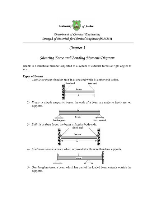
Beam: is a structural member subjected to a system of external forces at right angles to<br />
axis.<br />
Types of Beams<br />
1- Cantilever beam: fixed or built-in at one end while it’s other end is free.<br />
2- Freely or simply supported beam: the ends of a beam are made to freely rest on<br />
supports.<br />
3- Built-in or fixed beam: the beam is fixed at both ends.<br />
4- Continuous beam: a beam which is provided with more than two supports.<br />
5- Overhanging beam: a beam which has part of the loaded beam extends outside the<br />
supports.
Statically Determinate Beams<br />
Cantilever, simply supported, overhanging beams are statically determinate beams as the<br />
reactions of these beams at their supports can be determined by the use of equations of<br />
static equilibrium <strong>and</strong> the reactions are independent of the deformation of the beam.<br />
There are two unknowns only.<br />
Statically Indeterminate Beams<br />
Fixed <strong>and</strong> continuous beams are statically indeterminate beams as the reactions at<br />
supports cannot be determined by the use of equations of static equilibrium. There are<br />
more than two unknown.<br />
Types of Loads:<br />
1- Concentrated load assumed to act at a point <strong>and</strong> immediately introduce an<br />
oversimplification since all practical loading system must be applied over a finite<br />
area.<br />
2- Distributed load are assumed to act over part, or all, of the beam <strong>and</strong> in most cases<br />
are assumed to be equally or uniformly distributed.<br />
a- Uniformly distributed.<br />
b- Uniformly varying load.
<strong>Shearing</strong> <strong>Force</strong> (S.F.)<br />
<strong>Shearing</strong> force at the section is defined as the algebraic sum of the forces taken on one<br />
side of the section.<br />
<strong>Bending</strong> <strong>Moment</strong> (B.M)<br />
<strong>Bending</strong> moment is defined as the algebraic sum of the moments of the forces about the<br />
section, taken on either sides of the section.<br />
1. S.F.<strong>and</strong> B.M. <strong>Diagram</strong>s for Beams Carrying Concentrated Loads Only:
• If the S.F. is zero the bending moment will remain constant.<br />
• If the S.F. is positive the slope of the B.M. curve is positive.<br />
• If the S.F. is negative the slope of the B.M. curve is negative.<br />
• The difference in B.M. between any two points equals the area under the S.F.<br />
curve for the same points.<br />
• Between concentrated loads, there is no change in shear <strong>and</strong> the shear force curve<br />
plots as a straight horizontal line.<br />
• At each concentrated load or reaction, the value of the shear force changes<br />
abruptly by an amount equal to the load or reaction force.<br />
• The maximum bending moment occurs at a point where the shear curve crosses<br />
its zero axis.<br />
2. S.F.<strong>and</strong> B.M. <strong>Diagram</strong>s for Beams Carrying Distributed Loads Only:
3. S.F. <strong>and</strong> B.M. <strong>Diagram</strong>s for Beams Carrying Combined Concentrated <strong>and</strong><br />
Uniformly Distributed Loads:
Points of Contraflexure<br />
It is a point where the curvature of the beam changes sign <strong>and</strong> occurs at a point where the<br />
B.M. is zero (other than the ends).<br />
In order to find the exact location of the contraflexure point you have to solve <strong>and</strong> find<br />
the zeros of the bending moment equation applied in the interval where the curve crosses<br />
the zero line.<br />
For the above example find the zeros of the second order bending moment equation in the<br />
third interval.<br />
4. S.F. <strong>and</strong> B.M. <strong>Diagram</strong>s for Beams Carrying Couple or <strong>Moment</strong>:
At each couple or moment, the value of the bending moment changes abruptly by an<br />
amount equal to the couple or moment.<br />
Relationship between Shear <strong>Force</strong> <strong>and</strong> <strong>Bending</strong> <strong>Moment</strong><br />
dM<br />
• The maximum or minimum B.M. occurs where = S. F.<br />
= 0<br />
dx<br />
• Thus where S.F. is zero <strong>and</strong> crosses the zero axis B.M. is maximum or minimum.<br />
dM<br />
• If S.F. is zero then = 0 ⇒ ∫ dM = ∫ 0dx<br />
⇒ M = constant<br />
dx<br />
dM<br />
• Since = S.F.<br />
then where the S.F. is positive the slope of the B.M. diagram is<br />
dx<br />
positive, <strong>and</strong> where the S.F. is negative the slope of the B.M. diagram is also<br />
negative.<br />
• The area of the S.F. diagram between any two points, from basic calculus<br />
dM<br />
= S.<br />
F.<br />
⇒ ∫ dM = ∫ S.<br />
F.<br />
dx ⇒ M = ∫ S.<br />
F.<br />
dx<br />
dx