Christie Entero Projector and Cube Installation Manual
Christie Entero Projector and Cube Installation Manual
Christie Entero Projector and Cube Installation Manual

Create successful ePaper yourself
Turn your PDF publications into a flip-book with our unique Google optimized e-Paper software.
Projection Engines<br />
<strong>Entero</strong> RPMSP–LED01<br />
<strong>Entero</strong> RPMHD–LED01<br />
<strong>Entero</strong> RPMWU–LED 01<br />
<strong>Cube</strong>s<br />
CC50<br />
CC67<br />
CC70<br />
CC70HD<br />
CC72<br />
<strong>Installation</strong> <strong>Manual</strong><br />
020-100839-01<br />
<strong>Entero</strong> <strong>Projector</strong> <strong>and</strong> <strong>Cube</strong> <strong>Installation</strong> Guide 1<br />
020-100839-01 Rev. 1 (04-2013)
Projection Engines<br />
<strong>Entero</strong> RPMSP–LED01<br />
<strong>Entero</strong> RPMHD–LED01<br />
<strong>Entero</strong> RPMWU–LED01<br />
<strong>Cube</strong>s<br />
CC50<br />
CC67<br />
CC70<br />
CC72<br />
<strong>Installation</strong> <strong>Manual</strong><br />
020-100839-01
NOTICES<br />
COPYRIGHT AND TRADEMARKS<br />
© 2008 – 2013 <strong>Christie</strong> Digital Systems, Inc.–2012 <strong>Christie</strong> Digital Systems USA, Inc. All rights reserved. All br<strong>and</strong> names <strong>and</strong><br />
product names are trademarks, registered trademarks or trade names of their respective holders.<br />
REGULATORY<br />
The product has been tested <strong>and</strong> found to comply with the limits for a Class A digital device, pursuant to Part 15 of the FCC Rules.<br />
These limits are designed to provide reasonable protection against harmful interference when the product is operated in a<br />
commercial environment. The product generates, uses, <strong>and</strong> can radiate radio frequency energy <strong>and</strong>, if not installed <strong>and</strong> used in<br />
accordance with the instruction manual, may cause harmful interference to radio communications. Operation of the product in a<br />
residential area is likely to cause harmful interference in which case the user will be required to correct the interference at the<br />
expense of the user.<br />
This Class A digital apparatus complies with CAN ICES–3.<br />
Cet appareil numérique de la classe A est conforme à la norme NMB–3 (A) du Canada.<br />
이 기기는 업무용 (A 급 ) 으로 전자파적합등록을 한 기기이오니 판매자 또는 사용자는 이점을 주의하시기 바라며 , 가정 외의 지역에서<br />
사용하는 것을 목적으로 합니다 .<br />
GENERAL<br />
Every effort has been made to ensure accuracy, however in some cases changes in the products or availability could occur which<br />
may not be reflected in this document. <strong>Christie</strong> reserves the right to make changes to specifications at any time without notice.<br />
Performance specifications are typical, but may vary depending on conditions beyond the control of <strong>Christie</strong> such as maintenance of<br />
the product in proper working conditions. Performance specifications are based on information available at the time of printing.<br />
<strong>Christie</strong> makes no warranty of any kind with regard to this material, including, but not limited to, implied warranties of fitness for a<br />
particular purpose. <strong>Christie</strong> will not be liable for errors contained herein or for incidental or consequential damages in connection<br />
with the performance or use of this material.<br />
The product is designed <strong>and</strong> manufactured with high–quality materials <strong>and</strong> components that can be recycled <strong>and</strong> reused. This<br />
symbol means that electrical <strong>and</strong> electronic equipment, at their end–of–life, should be disposed of separately from regular<br />
waste. Please dispose of the product appropriately <strong>and</strong> according to local regulations. In the European Union, there are separate<br />
collection systems for used electrical <strong>and</strong> electronic products. Please help us to conserve the environment we live in!<br />
Canadian manufacturing facility is ISO 9001 <strong>and</strong> 14001 certified.<br />
GENERAL WARRANTY STATEMENTS<br />
For complete information about the <strong>Christie</strong> limited warranty, please contact your <strong>Christie</strong> dealer. In addition to the other limitations<br />
that may be specified in the <strong>Christie</strong> limited warranty, the warranty does not cover:<br />
a. Damage occurring during shipment, in either direction.<br />
b. <strong>Projector</strong> lamps (See the separate <strong>Christie</strong> lamp program policy).<br />
c. Damage caused by use of a projector lamp beyond the recommended lamp life, or use of a lamp supplied by a supplier<br />
other than <strong>Christie</strong>.<br />
d. Problems caused by combination of the product with non–<strong>Christie</strong> equipment, such as distribution systems, cameras,<br />
video tape recorders, etc., or use of the product with any non–<strong>Christie</strong> interface device.<br />
e. Damage caused by misuse, improper power source, accident, fire, flood, lightning, earthquake or other natural disaster.<br />
f. Damage caused by improper installation/alignment, or by product modification, if by other than a <strong>Christie</strong> authorized<br />
repair service provider.<br />
g. For LCD projectors, the warranty period specified applies only where the LCD projector is in “normal use.” “Normal<br />
use” means the LCD projector is not used more than 8 hours a day, 5 days a week. For any LCD projector where “normal<br />
use” is exceeded, warranty coverage under this warranty terminates after 6000 hours of operation.<br />
h. Failure due to normal wear <strong>and</strong> tear.<br />
PREVENTATIVE MAINTENANCE<br />
Preventative maintenance is an important part of the continued <strong>and</strong> proper operation of your product. Please see the Maintenance<br />
section for specific maintenance items as they relate to your product. Failure to perform maintenance as required, <strong>and</strong> in<br />
accordance with the maintenance schedule specified by <strong>Christie</strong>, will void the warranty.
Addendum<br />
The CD included with this printed manual contains an electronic copy in English. Please read all<br />
instructions before using or servicing this product.<br />
手 册 中 包 含 的 光 盘 , 带 有 着 中 文 的 电 子 副 本 , 使 用 或 维 修 本 产 品 前 , 请 仔 细 查 阅 所<br />
有 的 指 示 。<br />
Le DC fourni avec ce manuel imprimé contient une copie électronique en français. S'il vous plaît lire<br />
toutes les instructions avant d'utiliser ou de réparer ce produit.<br />
Das CD, das mit diesem gedruckten H<strong>and</strong>buch eingeschlossen ist, enthält eine elektronische Kopie auf in<br />
deutscher Sprache. Vor der Anwendung oder der Inst<strong>and</strong>haltung dieses Produktes lesen Sie bitte alle<br />
Anweisungen.<br />
Il CD fornito con il manuale stampato contiene una copia elettronica in lingua italiano. Si prega di leggere<br />
tutte le istruzioni prima di utilizzare o riparare questo prodotto.<br />
この 印 刷 されたマニュアルに 同 梱 されております CD には、 日 本 語 での 説 明 書 が 入 ってお<br />
ります。この 製 品 を 使 用 あるいは 修 理 点 検 される 際 に、ご 参 照 下 さい。<br />
매뉴얼과 함께 포함되어 있는 CD 에는 한글로 된 전자사본을 포함하고 있습니다 . 본<br />
제품을 사용 혹은 서비스하기 전에 모든 지침 사항들을 읽어 보시기 바랍니다 .<br />
O CD incluído com o impresso livro contém um eletrônico cópia em Português. Por favor lido todas as<br />
instruções antes de usar ou prest<strong>and</strong>o serviço esse resultado.<br />
Поставляемый в комплекте с документацией компакт-диск (CD) содержит<br />
электронную копию руководства пользователя на русском языке. Перед началом<br />
использования изделия или проведения сервиса пожалуйста прочтите все<br />
инструкции изложенные в руководстве.<br />
El DC incluido con este manual impreso contiene una copia electrónica en español. Por favor, lea todas las<br />
instrucciones antes de usar o dar servicio a este producto.<br />
Компакт диск, що постачається з цим друковане керівництво містить електронну<br />
копію українською мовою. Будь ласка, прочитайте всі інструкції перед використанням<br />
або обслуговуванням цього продукту.
Table of Contents<br />
1: Introduction<br />
1.1 Safety Warnings <strong>and</strong> Guidelines .................................................................................................1-1<br />
1.2 Contact Support ...........................................................................................................................1-2<br />
2: <strong>Cube</strong> <strong>Installation</strong> <strong>and</strong> Setup<br />
2.1 <strong>Christie</strong> Pedestals.........................................................................................................................2-1<br />
2.2 Stacking Limitations....................................................................................................................2-1<br />
2.3 Components <strong>and</strong> Hardware .........................................................................................................2-2<br />
2.3.1 <strong>Cube</strong> Enclosures ..................................................................................................................2-2<br />
2.3.2 Screens .................................................................................................................................2-2<br />
2.3.3 Pedestals...............................................................................................................................2-2<br />
2.3.4 <strong>Entero</strong> <strong>Projector</strong>s..................................................................................................................2-3<br />
2.3.5 Recommended <strong>Installation</strong> Tools ........................................................................................2-3<br />
2.4 Unpack <strong>Cube</strong> Enclosures <strong>and</strong> Pedestals ......................................................................................2-4<br />
2.5 Unpack <strong>and</strong> Stabilize Screens......................................................................................................2-5<br />
2.6 Install the Pedestals .....................................................................................................................2-5<br />
2.6.1 Construct a Multiple Pedestal Platform...............................................................................2-6<br />
2.7 Install Display <strong>Cube</strong> Enclosures..................................................................................................2-8<br />
2.8 Install Permanent External Support.............................................................................................2-11<br />
2.8.1 Tieback Application.............................................................................................................2-11<br />
2.8.2 Lag Bolt Application ...........................................................................................................2-12<br />
2.9 Install Screens..............................................................................................................................2-13<br />
3: <strong>Projector</strong> <strong>Installation</strong> <strong>and</strong> Setup<br />
3.1 What’s in the Box ........................................................................................................................3-1<br />
3.2 Unpack <strong>Projector</strong>s........................................................................................................................3-1<br />
3.3 <strong>Projector</strong> Components .................................................................................................................3-2<br />
3.3.1 Projection Head Module (PHM)..........................................................................................3-2<br />
3.3.2 Light Module (LM)..............................................................................................................3-2<br />
3.3.3 Electronics Module (EM) ....................................................................................................3-2<br />
3.4 Install <strong>Projector</strong>s into <strong>Cube</strong> Enclosures.......................................................................................3-3<br />
3.4.1 Tools <strong>and</strong> Hardware Required .............................................................................................3-3<br />
3.5 Installing the <strong>Projector</strong> in a Custom Structure.............................................................................3-5<br />
3.5.1 Change <strong>Projector</strong> Orientation for Direct Throw <strong>Installation</strong>s .............................................3-5<br />
3.6 Wiring..........................................................................................................................................3-7<br />
3.6.1 Tips for Running External Cables to <strong>Projector</strong>s ..................................................................3-7<br />
3.6.2 Connect the PHM to the EM <strong>and</strong> AC ..................................................................................3-8<br />
3.6.3 Connect <strong>Projector</strong>s for External Communication................................................................3-9<br />
Ethernet .................................................................................................................................3-9<br />
Mixed Network .....................................................................................................................3-10<br />
RS232 Network ....................................................................................................................3-11<br />
Mixed Serial Network (RS232 <strong>and</strong> RS422) .........................................................................3-12<br />
3.7 Connect <strong>Projector</strong>s for ArrayLOC...............................................................................................3-13<br />
3.7.1 Hardware Requirements ......................................................................................................3-13<br />
3.7.2 ArrayLOC Over PHM Network ..........................................................................................3-14<br />
<strong>Entero</strong> <strong>Projector</strong> <strong>and</strong> <strong>Cube</strong> <strong>Installation</strong> <strong>Manual</strong><br />
020-100839-01 Rev. 2 (04-2013)<br />
i
Table of Contents<br />
Calculate Your Hardware Requirement ................................................................................3-14<br />
PHM Network Example: 2 x 3 Wall .....................................................................................3-14<br />
PHM Network Example: 4 x 6 wall ......................................................................................3-15<br />
3.7.3 ArrayLOC Over EM Network .............................................................................................3-15<br />
Calculate Hardware Requirements .......................................................................................3-16<br />
EM Network Example: 2 x 3 Wall .......................................................................................3-16<br />
EM Network Example: 4 x 6 Wall .......................................................................................3-17<br />
3.7.4 Enable ArrayLOC ................................................................................................................3-18<br />
3.8 Source Connections .....................................................................................................................3-18<br />
3.8.1 DVI Digital Video................................................................................................................3-18<br />
3.8.2 Dual Link DVI Input Card ...................................................................................................3-19<br />
3.8.3 Twin HDMI Input Card .......................................................................................................3-19<br />
3.8.4 Analog BNC Input Card ......................................................................................................3-20<br />
3.8.5 Dual SD/HD – SDI Input Card ............................................................................................3-20<br />
3.8.6 Video Decoder Input Card ...................................................................................................3-21<br />
3.9 System Integration – GPIO Connector ........................................................................................3-22<br />
4: Adjust the Image<br />
4.1 Adjustment Tips...........................................................................................................................4-1<br />
4.2 Power the <strong>Projector</strong> On................................................................................................................4-1<br />
4.3 Focus .64:1 Fixed Lens................................................................................................................4-2<br />
4.4 Adjust Image Geometry Using the 6–axis Adjuster ....................................................................4-3<br />
4.5 Fine–tune Image Geometry using the Mirror ..............................................................................4-5<br />
4.5.1 Mirror Adjustment Screws...................................................................................................4-6<br />
4.5.2 Adjust the Mirror .................................................................................................................4-6<br />
4.5.3 Image Geometry Troubleshooting using the Mirror ............................................................4-7<br />
4.5.4 Barrel <strong>and</strong> Pincushion Distortion.........................................................................................4-9<br />
4.6 Optimize Image Setup <strong>and</strong> Display .............................................................................................4-9<br />
4.6.1 Initialization <strong>and</strong> Auto Setup ...............................................................................................4-9<br />
4.6.2 Adjust Image Geometry Using the <strong>Projector</strong> Software .......................................................4-10<br />
4.6.3 Adjust Black Levels <strong>and</strong> Input Drives .................................................................................4-10<br />
4.7 Adjust Color Using ArrayLOC....................................................................................................4-10<br />
4.8 Adjust Brightness Uniformity......................................................................................................4-11<br />
4.8.1 Cancel Brightness Uniformity .............................................................................................4-11<br />
5: Troubleshooting<br />
5.1 System Warnings <strong>and</strong> Errors .......................................................................................................5-1<br />
5.2 Error Codes ..................................................................................................................................5-2<br />
5.3 LED Status Indicators.................................................................................................................5-3<br />
5.4 <strong>Projector</strong> Does Not Turn On........................................................................................................5-4<br />
5.5 Light Module Suddenly Goes Off ...............................................................................................5-4<br />
5.6 No Display When the <strong>Projector</strong> is On..........................................................................................5-4<br />
5.7 The Display is Unstable...............................................................................................................5-4<br />
5.8 The Display is Faint.....................................................................................................................5-4<br />
5.9 The Upper Portion of the Display is Waving, Tearing or Jittering..............................................5-5<br />
ii<br />
<strong>Entero</strong> <strong>Projector</strong> <strong>and</strong> <strong>Cube</strong> <strong>Installation</strong> <strong>Manual</strong><br />
020-100839-01 Rev. 2 (04-2013)
Table of Contents<br />
5.10 Portions of the Display are Cut Off or Warped to the Opposite Edge ......................................5-5<br />
5.11 Display Appears Compressed (Vertically Stretched)................................................................5-5<br />
5.12 Data is Cropped from Edges......................................................................................................5-5<br />
5.13 Inconsistent Picture Quality.......................................................................................................5-5<br />
5.14 Static Display.............................................................................................................................5-5<br />
5.15 Inaccurate Display Colors .........................................................................................................5-5<br />
5.16 Display is Not Rectangular........................................................................................................5-5<br />
5.17 Display is Noisy.........................................................................................................................5-6<br />
6: Maintenance<br />
6.1 Ventilation ...................................................................................................................................6-1<br />
6.2 Clean the Mirror ..........................................................................................................................6-1<br />
6.2.1 Items Required.....................................................................................................................6-1<br />
6.2.2 Prerequisites.........................................................................................................................6-1<br />
6.2.3 Instructions...........................................................................................................................6-1<br />
Remove Water Droplet rings, marks, <strong>and</strong> other surface stains ............................................6-1<br />
Remove Finger Prints ...........................................................................................................6-2<br />
6.3 Clean the Screen ..........................................................................................................................6-2<br />
6.3.1 Items Required.....................................................................................................................6-2<br />
6.3.2 Prerequisites.........................................................................................................................6-2<br />
6.3.3 Instructions...........................................................................................................................6-2<br />
6.4 Clean the Projection Lens............................................................................................................6-3<br />
6.4.1 Items Required.....................................................................................................................6-3<br />
6.4.2 Instructions...........................................................................................................................6-3<br />
Remove Dust ........................................................................................................................6-3<br />
Remove Fingerprints, Smudges, or Oil ................................................................................6-3<br />
A: Specifications<br />
A.1 CC50 Specifications ...................................................................................................................A-2<br />
A.1.1 CC50 Brightness <strong>and</strong> Performance Characteristics ............................................................A-3<br />
A.2 CC67 Specifications ...................................................................................................................A-4<br />
A.2.1 CC67 Brightness <strong>and</strong> Performance Characteristics ............................................................A-5<br />
A.3 CC70 Specifications ...................................................................................................................A-6<br />
A.3.1 CC70 Brightness <strong>and</strong> Performance Characteristics ............................................................A-7<br />
A.4 CC72 Specifications ...................................................................................................................A-8<br />
A.4.1 CC72 Brightness <strong>and</strong> Performance Characteristics ...........................................................A-9<br />
<strong>Entero</strong> <strong>Projector</strong> <strong>and</strong> <strong>Cube</strong> <strong>Installation</strong> <strong>Manual</strong><br />
020-100839-01 Rev. 2 (04-2013)<br />
iii
1 Introduction<br />
This manual provides instructions for installing a display system using <strong>Christie</strong> <strong>Entero</strong> RPMSP–LED01,<br />
RPMWU–LED01 or RPMHD–LED01 projectors, CC50, CC67, CC70, CC70HD <strong>and</strong> CC72 display cubes,<br />
<strong>and</strong> PE50, PE67, PE70, PE70HD <strong>and</strong> PE72 pedestals.<br />
The information within this manual is intended for audio visual technicians with experience installing display<br />
systems. To avoid personal injury or damage to the projector, read all procedures before starting the installation<br />
<strong>and</strong> observe all precautions. For information on installing the projector in a non–<strong>Christie</strong> enclosure, contact<br />
your dealer. For information about using the projector, see RPMSP/RPMWU/RPMHD–LED01 User <strong>Manual</strong><br />
(P/N: 020-100367-xx).<br />
1.1 Safety Warnings <strong>and</strong> Guidelines<br />
Failure to comply with the following may result in death or serious injury:<br />
• Tip Load! The maximum stacking limitation is 5 cubes high in a minimum 2 column display wall. The<br />
display wall must be properly anchored anytime the wall is 2 rows or higher to prevent tipping <strong>and</strong><br />
provide stability. Use all the hardware provided to fasten the display cubes to the support structure.<br />
See 2.8 Install Permanent External Support, on page 2-11.<br />
• Disconnect the AC cord before disconnecting the light module from the <strong>Projector</strong> Head Module<br />
(PHM).<br />
Failure to comply with the following could result in minor or moderate injury:<br />
• Do not look directly into the projection lens. The high brightness of this projector could cause permanent<br />
eye damage. For protection, keep all projector shielding intact during operation.<br />
• Lift equipment must be used to lift the display cubes into position on rows 2 or higher. A crew of 2 or<br />
more can lift a display cube into position on the first row.<br />
• Always power down <strong>and</strong> disconnect/disengage all power sources to the projector before servicing or<br />
cleaning.<br />
• Mount the projector in a <strong>Christie</strong> display cube or to a sturdy, flat surface that fits the entire projector.<br />
Use all 4 mounting points to secure the projector to the surface.<br />
• Power should always be disconnected from<br />
the light module before servicing, to avoid<br />
the possibility of inadvertent exposure to visible<br />
LED radiation. Directly viewing the light<br />
module optical output through certain optical<br />
instruments (for example, eye loupes, magnifiers<br />
<strong>and</strong> microscopes) within a distance of<br />
100 mm (3.94”) may pose an eye hazard.<br />
<strong>Entero</strong> <strong>Projector</strong> <strong>and</strong> <strong>Cube</strong> <strong>Installation</strong> <strong>Manual</strong> 1-1<br />
020-100839-01 Rev. 2 (04-2013)
NOTICES: <br />
Failure to comply with the following may result in equipment damage:<br />
• Maintain a minimum clearance of 25 mm (1.0”) around the projector for air circulation <strong>and</strong> a 75 mm (3”) clearance<br />
for cable connections to the input panel. Insufficient clearance can cause the projector to overheat during operation<br />
<strong>and</strong>/or place undue stress on source connections.<br />
• This projector must be operated in an environment that meets the operating range specification, as listed in Appendix<br />
A Specifications.<br />
1.2 Contact Support<br />
Trained service technicians are available to diagnose <strong>and</strong> correct system–related problems. If you encounter<br />
any problems during the setup <strong>and</strong> installation of your system, contact the authorized dealer or <strong>Christie</strong> Partner<br />
from whom the system was purchased.<br />
1-2 <strong>Entero</strong> <strong>Projector</strong> <strong>and</strong> <strong>Cube</strong> <strong>Installation</strong> <strong>Manual</strong><br />
020-100839-01 Rev. 2 (04-2013)
2 <strong>Cube</strong> <strong>Installation</strong> <strong>and</strong> Setup<br />
NOTICE: Only qualified installers should attempt installation of a <strong>Christie</strong> display wall.<br />
NOTE: A clearance of 3 ft or more is recommended behind the display cube for serviceability <strong>and</strong> installation.<br />
2.1 <strong>Christie</strong> Pedestals<br />
<strong>Christie</strong> pedestals (models PE50, PE67, PE70, PE70HD, PE72) are recommended when you install <strong>Christie</strong><br />
display cubes (models CC50, CC67, CC70, CC70HD, CC72).<br />
2.2 Stacking Limitations<br />
Tip Load! The maximum stacking limitation is 5 cubes high in a minimum 2 column<br />
display wall. The display wall must be properly anchored anytime the wall is 2 rows or higher to prevent<br />
tipping <strong>and</strong> provide stability. Use all the hardware provided to fasten the display cubes to the support<br />
structure. See 2.8 Install Permanent External Support, on page 2-11.<br />
When stacking display cubes, they must be installed on a level surface. If the surface is not level the stacked<br />
cubes could tip over <strong>and</strong> cause personal injury or damage to the cubes. Stacking limitations apply to all the<br />
display cube models; the CC50, CC67, CC70, CC70HD, <strong>and</strong> CC80. Anytime the display wall is 2 rows or<br />
higher the wall must be anchored to prevent tipping <strong>and</strong> provide stability. <strong>Christie</strong> recommends either using<br />
tiebacks or lag bolts to secure the display wall. For details, see 2.8 Install Permanent External Support, on<br />
page 2-11. Do not stack display cubes higher than the specified stacking limits. Stacking display cubes higher<br />
than what is recommended increases the possibility of the display wall becoming unstable <strong>and</strong> unsafe. It also<br />
increases the chance that the pedestals may buckle from the extra weight.death or serious injury.<br />
STACKING HEIGHT<br />
(2 COLUMNS WIDE OR MORE)<br />
ANCHORING REQUIRED<br />
1 No<br />
2 Yes<br />
3 Yes<br />
4 Yes<br />
5 Yes<br />
<strong>Entero</strong> <strong>Projector</strong> <strong>and</strong> <strong>Cube</strong> <strong>Installation</strong> <strong>Manual</strong> 2-1<br />
020-100839-01 Rev. 2 (04-2013)
2.3 Components <strong>and</strong> Hardware<br />
All major components required to assemble a complete display cube are packaged <strong>and</strong> shipped separately to<br />
the installation site. This includes the display cube enclosure, projector, display screen, <strong>and</strong> pedestal. Each<br />
component comes with the hardware required for installation. Check the contents of your shipment against the<br />
list below to make sure that you have all the necessary hardware. Hardware is listed by component <strong>and</strong> applies<br />
to all models unless otherwise noted.<br />
2.3.1 <strong>Cube</strong> Enclosures<br />
• M6 x 75mm hex screws (Qty. 10)<br />
• M6 x 18mm flat washers (Qty. 20)<br />
• M6 lock washers (Qty. 10)<br />
• M6 hex nuts (Qty. 10)<br />
• M6 x 60mm hex screws (Qty. 2)<br />
• M6 x 24mm flat washers (Qty. 4)<br />
• Cable covers<br />
• Long-screen bolts (Qty. 4)<br />
• Short-screen bolts (Qty. 2)<br />
•Panel plug<br />
2.3.2 Screens<br />
• M6 screws (Qty. 8)<br />
• M8 set screws (Qty. 4)<br />
NOTE: The long <strong>and</strong> short-screen bolts required to secure a screen to the cube are shipped with the cube.<br />
2.3.3 Pedestals<br />
• M6 x 75mm hex screws (Qty. 4)<br />
• M6 flat washers (Qty. 8)<br />
• M6 lock washers (Qty. 4)<br />
• M6 hex nuts (Qty. 4)<br />
• Cable covers (Qty. 4)<br />
2-2 <strong>Entero</strong> <strong>Projector</strong> <strong>and</strong> <strong>Cube</strong> <strong>Installation</strong> <strong>Manual</strong><br />
020-100839-01 Rev. 2 (04-2013)
2.3.4 <strong>Entero</strong> <strong>Projector</strong>s<br />
Each display wall requires a User Kit (P/N: 125-108100-xx). One User Kit is provided with each order, <strong>and</strong> 2<br />
are provided with every 4 or more units ordered.<br />
•Power Cord<br />
• <strong>Entero</strong> User Kit (P/N:125-108100-xx).<br />
Each kit includes:<br />
• <strong>Entero</strong> <strong>Projector</strong> <strong>and</strong> <strong>Cube</strong> <strong>Installation</strong> Guide (this manual, P/N: 020-100839-xx)<br />
• <strong>Entero</strong> RPMSP/RPMWU–LED01 User <strong>Manual</strong> (P/N: 020-100367-xx)<br />
• IR remote control with 2 AA batteries<br />
• Ball drivers: 8 mm, 5 mm, 4 mm (long), 2 mm<br />
• Lint–free gloves (required for mirror <strong>and</strong> screen h<strong>and</strong>ling)<br />
2.3.5 Recommended <strong>Installation</strong> Tools<br />
•Level<br />
• 10 mm hex wrench or socket driver<br />
• 5 mm ball driver (provided with the user kit)<br />
• 4 mm ball driver (provided with the user kit)<br />
• Adjustable wrench<br />
• Torque wrench<br />
• #2 Phillips screwdriver<br />
<strong>Entero</strong> <strong>Projector</strong> <strong>and</strong> <strong>Cube</strong> <strong>Installation</strong> <strong>Manual</strong> 2-3<br />
020-100839-01 Rev. 2(04-2013)
2.4 Unpack <strong>Cube</strong> Enclosures <strong>and</strong> Pedestals<br />
NOTICES:<br />
Failure to comply with the following may result in equipment damage:<br />
• Do not cut the protective film off the mirror with a knife.<br />
• Do not touch the optical mirror with your bare h<strong>and</strong>s. Fingerprints left on the surface can impact image<br />
quality.<br />
1. Lift the cardboard packaging off of the cube enclosures <strong>and</strong> pedestals. Do not cut the packaging with a<br />
knife.<br />
CC50<br />
CC70<br />
6<br />
1<br />
4<br />
2<br />
3<br />
5<br />
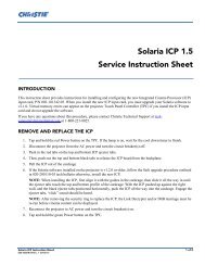
1, 3 Cable covers<br />
2 CC50 back panel. Similar for CC72.<br />
4 3 rear access panels for CC67, CC70, <strong>and</strong> CC70HD<br />
5 Rear access panel spring release<br />
6 Panel plugs<br />
2. Remove the back panels <strong>and</strong> set aside in a location where the panels will not be damaged.<br />
• CC50/CC72 panels are secured with 10 screws in keyhole slots. To remove the panel, loosen the<br />
screws <strong>and</strong> slide the panel up.<br />
• CC67/CC70/CC70HD panels are secured with 2 spring clips each. Press down on the spring clips<br />
<strong>and</strong> tilt the top of the panel out. Lift the panel away.<br />
3. Put on the lint–free cotton gloves from the user kit <strong>and</strong> remove the protective film from the optical mirror.<br />
Do not bump or scratch the mirror during unpacking.<br />
4. Install a cable cover over each exposed opening. See the illustration above.<br />
2-4 <strong>Entero</strong> <strong>Projector</strong> <strong>and</strong> <strong>Cube</strong> <strong>Installation</strong> <strong>Manual</strong><br />
020-100839-01 Rev. 2 (04-2013)
2.5 Unpack <strong>and</strong> Stabilize Screens<br />
1. Wear the lint–free cotton gloves provided in the user kit, remove the screen from the packaging <strong>and</strong> st<strong>and</strong><br />
it vertically against a wall or flat surface. Select a low–traffic area away from the installation to protect the<br />
screens from accidental scratching or tipping.<br />
2. Let the screen stabilize to ambient site conditions for a minimum 24 hours.<br />
3. Wearing lint-free cotton gloves, remove the protective film from the back of the screen.<br />
2.6 Install the Pedestals<br />
When you install <strong>Christie</strong> display cubes, <strong>Christie</strong> recommends that you use a <strong>Christie</strong> pedestal which is<br />
designed to support the maximum stacking limit of the display cubes. Alternatively, custom designed pedestals<br />
can be used; however, it is the responsibility of the designer/installer to make sure the custom structure meets<br />
performance <strong>and</strong> safety requirements.<br />
CUBE<br />
CC50<br />
CC67<br />
CC70<br />
CC70HD<br />
CC72<br />
PEDESTAL<br />
PE50<br />
PE67<br />
PE70<br />
PE70HD<br />
PE72<br />
<strong>Entero</strong> <strong>Projector</strong> <strong>and</strong> <strong>Cube</strong> <strong>Installation</strong> <strong>Manual</strong> 2-5<br />
020-100839-01 Rev. 2(04-2013)
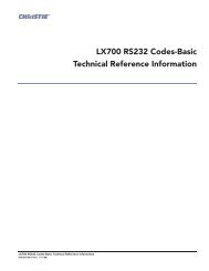
3<br />
2<br />
2<br />
2<br />
3<br />
2<br />
4<br />
1<br />
1<br />
1<br />
1<br />
5<br />
1 Use to fasten pedestals together, 4 on each side panel<br />
2 Use to install display cubes, 2 at the back <strong>and</strong> 2 at the front<br />
3 On PE67/PE70/PE72 pedestals only, use to install display cubes, 2 on support bracket<br />
4 Front Panel (faces the room)<br />
5 Adjustable feet (Qty. 4)<br />
2.6.1 Construct a Multiple Pedestal Platform<br />
Before starting, check that you have all the required hardware. See 2.3 Components <strong>and</strong> Hardware.<br />
Failure to comply with the following could result in minor or moderate injury:<br />
• Make sure that the appropriately rated lifting equipment <strong>and</strong> a minimum of 2 people are available for<br />
installation.<br />
• Mount the pedestals on a permanent, hard surface such as a concrete floor. Elevated surfaces, such as<br />
wood platforms are not recommended.<br />
<br />
NOTES: 1) Always start at the center <strong>and</strong> work outward, ensuring each pedestal is level. 2) Do not fully<br />
tighten the hardware that attaches pedestals together until you have completed all of your adjustments <strong>and</strong><br />
installed all of the pedestals.<br />
1. Slide 2 pedestals together <strong>and</strong> align the front <strong>and</strong> rear edges.<br />
2. Apply downward pressure on the pedestal to make sure that the feet are flat to the floor.<br />
3. Match the height of adjacent pedestals. Turn the bottom nut on each pedestal foot to raise or lower the<br />
pedestal.<br />
4. Use a level to verify that the pedestal is level on all sides <strong>and</strong> with the other pedestal.<br />
2-6 <strong>Entero</strong> <strong>Projector</strong> <strong>and</strong> <strong>Cube</strong> <strong>Installation</strong> <strong>Manual</strong><br />
020-100839-01 Rev. 2 (04-2013)
5. Tighten the middle nut against the top nut to lock the pedestal foot in position.<br />
6. Check that you can see threads inside the pedestal, at the top of the corner bracket where the foot is<br />
installed. If threads are not visible, then you have over–extended the pedestal foot. Readjust the foot before<br />
continuing with the installation.<br />
7. H<strong>and</strong>-tighten the 2 pedestals together using 4 M6 x 75mm hex screws, 8 flat washers, 4 lock washers, <strong>and</strong><br />
4 M6 hex nuts. Make sure that the vertical seam between adjacent pedestals is as narrow as possible <strong>and</strong><br />
uniform from top to bottom.<br />
8. Slide the next pedestal into position <strong>and</strong> repeat steps 2 to 7.<br />
9. Confirm that the platform is level <strong>and</strong> that all of the rear edges of the pedestals are aligned.<br />
10. To secure the pedestals, tighten the loose hardware to a maximum torque setting of 11.1 Nm / 98 lbf-in.<br />
11. Use a level to confirm that the platform structure is level.<br />
<strong>Entero</strong> <strong>Projector</strong> <strong>and</strong> <strong>Cube</strong> <strong>Installation</strong> <strong>Manual</strong> 2-7<br />
020-100839-01 Rev. 2(04-2013)
2.7 Install Display <strong>Cube</strong> Enclosures<br />
Failure to comply with the following may result in death or serious injury:<br />
• Tip Load! The maximum stacking limitation is 5 cubes high in a minimum 2 column display wall. The<br />
display wall must be properly anchored anytime the wall is 2 rows or higher to prevent tipping <strong>and</strong><br />
provide stability. Use all the hardware provided to fasten the display cubes to the support structure.<br />
See 2.8 Install Permanent External Support, on page 2-11.<br />
• When stacking display cubes, they must be installed on a level surface. If the surface is not level the<br />
stacked cubes could tip over <strong>and</strong> cause personal injury or damage to the cubes.<br />
• Appropriate lift equipment must be used to list display cubes onto rows 2 or higher.<br />
NOTE: A clearance of 3 ft. or more is recommended behind the display cubes for serviceability <strong>and</strong><br />
installation.<br />
Before starting, check that you have all the required hardware. See 2.3 Components <strong>and</strong> Hardware. Complete<br />
each row of cube enclosures before starting the next. Proper alignment reduces issues with image geometry <strong>and</strong><br />
makes sure that the wall has a seamless appearance. Once the wall is installed, it is difficult <strong>and</strong> timeconsuming<br />
to fix an alignment problem near the bottom of a wall.<br />
1<br />
1<br />
3<br />
2<br />
3<br />
2<br />
2<br />
1 Use to fasten side–by–side display cubes together, <br />
4 on each side panel.<br />
2 Use to fasten the display cube to the pedestal or to the <br />
cube below, 2 at the back <strong>and</strong> 2 at the front.<br />
1<br />
1<br />
3 For CC67/CC70/CC72 display cubes only, use to fasten<br />
the display cube to the pedestal or cube below it, 2 on<br />
the support bracket.<br />
2-8 <strong>Entero</strong> <strong>Projector</strong> <strong>and</strong> <strong>Cube</strong> <strong>Installation</strong> <strong>Manual</strong><br />
020-100839-01 Rev. 2 (04-2013)
1. If space behind the display wall is limited, it is recommended the long-screen<br />
bolts are inserted into the back of the cubes before the cubes are installed.<br />
2. Install the first row of cube enclosures starting from the center <strong>and</strong> working<br />
outwards.<br />
a. From the back of the display structure, lift the cube enclosure over the<br />
pedestal or cube row <strong>and</strong> lower it in the center of the pedestal or cube. A<br />
crew of 2 or more can lift a display cube into position on the first row.<br />
b. With the display cube enclosure resting on the lower level, adjust its<br />
alignment so that the side <strong>and</strong> rear edges between the 2 components are<br />
flush <strong>and</strong> the mounting holes are aligned.<br />
short bolts<br />
(used only on top row)<br />
long screen bolts<br />
Side View<br />
c. Use 6 M6 x 75 mm screws (4 for CC50) with washers <strong>and</strong> hex nuts to secure the cube to the pedestal<br />
or cube in the lower level. To allow for small adjustments, do not fully tighten the mounting hardware.<br />
NOTE: For a single, st<strong>and</strong>–alone unit, tighten the hardware until components are fully secured, then<br />
proceed to 2.9 Install Screens, on page 2-13.<br />
d. Use 4 M6 x 75 mm screws with washers <strong>and</strong> hex nuts to attach the cube to the one adjacent to it. H<strong>and</strong><br />
tighten the mounting hardware.<br />
<strong>Entero</strong> <strong>Projector</strong> <strong>and</strong> <strong>Cube</strong> <strong>Installation</strong> <strong>Manual</strong> 2-9<br />
020-100839-01 Rev. 2(04-2013)
3. Loosen each of the adjustment screws on the optical mirror to minimize<br />
tension against the mirror at each adjustment point.<br />
4. Check the alignment between all of the display cubes <strong>and</strong> make<br />
adjustments as required. All cubes must be aligned vertically <strong>and</strong><br />
horizontally.<br />
5. Tighten all mounting hardware between the display cubes <strong>and</strong> pedestals<br />
before installing another row of display cubes. Tighten hardware to a<br />
maximum torque setting of 11.1 Nm / 98 lbf.-in.<br />
6. Make sure that the wall is externally supported before adding the<br />
second row of display cubes. See 2.8 Install Permanent External<br />
Support, on page 2-11.<br />
7. To add the next row of cube enclosures, repeat the installation<br />
instructions from step 1.<br />
2-10 <strong>Entero</strong> <strong>Projector</strong> <strong>and</strong> <strong>Cube</strong> <strong>Installation</strong> <strong>Manual</strong><br />
020-100839-01 Rev. 2 (04-2013)
2.8 Install Permanent External Support<br />
Tip Load! The maximum stacking limitation is 5 cubes high in a minimum 2<br />
column display wall. The display wall must be properly anchored anytime the wall is 2 rows<br />
or higher to prevent tipping <strong>and</strong> provide stability. Use all the hardware provided to fasten<br />
the display cubes to the support structure.<br />
When stacking display cubes, they must be installed on a level surface. If the surface is not<br />
level the stacked cubes could tip over <strong>and</strong> cause personal injury or damage to the cubes.<br />
Failure to comply may result in death or serious injury.<br />
External support for a display wall must be designed <strong>and</strong> implemented by a qualified<br />
installer <strong>and</strong> must comply to local area safety st<strong>and</strong>ards. All display walls must have permanent external<br />
supports. Failure to comply could result in minor or moderate injury.<br />
All display walls must be supported externally anytime the display wall is 2 rows or higher. External support<br />
prevents the wall from tipping <strong>and</strong> causing personal injury or damage to the display cubes. <strong>Christie</strong> requires<br />
that either the tieback or the lag bolt application is used to support a display wall.<br />
2.8.1 Tieback Application<br />
Every column of cubes requires 1 tie back. Each tieback must be capable of withst<strong>and</strong>ing a pull out force of<br />
500 lbs.<br />
DANGER! The amount of external support required is dependent on the size of<br />
the display wall. Support structures must be designed <strong>and</strong> implemented by a<br />
qualified installer <strong>and</strong> comply to local area safety st<strong>and</strong>ards.<br />
Failure to comply results in death or serious injury.<br />
<strong>Entero</strong> <strong>Projector</strong> <strong>and</strong> <strong>Cube</strong> <strong>Installation</strong> <strong>Manual</strong> 2-11<br />
020-100839-01 Rev. 2(04-2013)
2.8.2 Lag Bolt Application<br />
Each column of cubes requires 4 lag bolts. Each lag bolt must be capable of withst<strong>and</strong>ing a pull out force of<br />
500 lbs.<br />
DANGER! The amount of external support required is dependent on the size of<br />
the display wall. Support structures must be designed <strong>and</strong> implemented by a<br />
qualified installer <strong>and</strong> comply to local area safety st<strong>and</strong>ards.<br />
Failure to comply results in death or serious injury.<br />
2-12 <strong>Entero</strong> <strong>Projector</strong> <strong>and</strong> <strong>Cube</strong> <strong>Installation</strong> <strong>Manual</strong><br />
020-100839-01 Rev. 2 (04-2013)
2.9 Install Screens<br />
NOTICE:<br />
Failure to comply with the following may result in equipment damage:<br />
• Read this entire section before installing the screens.<br />
• Wear the lint-free gloves provided in the user kit when h<strong>and</strong>ling the screens to prevent leaving fingerprints on<br />
the surface.<br />
• Start with the center cube of the first row <strong>and</strong> work outwards.<br />
• Check that you have all the required hardware. See 2.3 Components <strong>and</strong> Hardware.<br />
1. Install the M6 depth adjustment screws <strong>and</strong> the M8 vertical alignment screws into the designated positions<br />
on the screen. Make sure the screws are flush with the frame.<br />
Insert M6 Depth Adjustment Screw<br />
Insert Long–Screen Bolt<br />
Insert M8 Vertical Alignment Screw<br />
2. Working with a partner, lift the screen into position at the front of the display cube. Align the screen with<br />
the cube face.<br />
3. With 1 person supporting the screen from the front, secure the screen to the display cube using 4 long–<br />
screen bolts. H<strong>and</strong>-tighten the mounting hardware. Leave enough play to allow for alignment adjustments.<br />
Install the long-screen bolts from the rear of the display cube <strong>and</strong> run them through the body of the cube.<br />
4. For screens on the top row, use 2 long-screen bolts to secure the bottom of the screen <strong>and</strong> 2 short M6 x 60<br />
mm screws to secure the top. Each M6 x 60 mm screw should have 2 M6 x 24 mm washers on it. <br />
NOTE: Always complete installing screens on the first row before starting onto the next row.<br />
5. Check <strong>and</strong> correct alignment <strong>and</strong> screen gap issues before adding another screen. NOTE: These<br />
adjustments require 2 people. One person to make the adjustments on the inside of the frame <strong>and</strong> the other<br />
person to check the adjustments on the outside of the frame.<br />
a. For depth adjustment: Insert 4 M6 screws at each corner of the screen, from the inside of the frame<br />
so that the screw surfaces are flush. Turn a screw clockwise to push the corresponding corner out from<br />
the cube body.<br />
<strong>Entero</strong> <strong>Projector</strong> <strong>and</strong> <strong>Cube</strong> <strong>Installation</strong> <strong>Manual</strong> 2-13<br />
020-100839-01 Rev. 2(04-2013)
. For vertical adjustment: Insert 2 M8 vertical alignment screws at each end of the screen, from the<br />
inside of the frame so that they are flush with the inside surface of the screen frame. Turn a screw<br />
clockwise to increase the height on that side of the screen. Use vertical adjustments to equalize the<br />
seams between the cubes.<br />
Screen adjustment screws<br />
H<strong>and</strong>–tighten<br />
long–screen bolts<br />
before setting<br />
screen gap<br />
short– screen bolts<br />
(for top row only)<br />
From inside screen,<br />
raise or lower<br />
screen adjustment<br />
screws to adjust<br />
screen gap<br />
0.5 mm<br />
Side View<br />
6. For the bottom row only, adjust the screen height so that the screen touches the pedestals to prevent the<br />
screen from shifting.<br />
7. Repeat steps 1 to 4 to install additional screens in the row. Leave a 0.5 mm (0.019”) gap between each<br />
screen. Work from the center outwards.<br />
8. Check <strong>and</strong> correct alignment <strong>and</strong> screen gap issues before adding a row of screens. Misalignment is<br />
difficult to correct once all screens are in place.<br />
9. Repeat steps 1 to 7 to install additional rows. As rows are added, adjust the screen depth adjustment screws<br />
to make sure the screen is flat.<br />
10. Once the second row of screens has been installed, adjust the depth screws on the first row of screens, <strong>and</strong><br />
tighten the long–screen bolts to lock in place.<br />
11. Once the third row of screens has been installed, adjust the depth screws on the second row, <strong>and</strong> tighten the<br />
long–screen bolts to lock in place.<br />
12. Continue until all rows have been completed.<br />
13. Tighten all screen mounting hardware to a maximum torque setting of 4.5 Nm / 39.6 lbf.in.<br />
2-14 <strong>Entero</strong> <strong>Projector</strong> <strong>and</strong> <strong>Cube</strong> <strong>Installation</strong> <strong>Manual</strong><br />
020-100839-01 Rev. 2 (04-2013)
3 <strong>Projector</strong> <strong>Installation</strong> <strong>and</strong> Setup<br />
The projector is designed for installation in a <strong>Christie</strong> cube display or a custom display structure. Before<br />
installing projectors, make sure that the screens have been installed <strong>and</strong> that screen depth <strong>and</strong> height<br />
adjustments are complete.<br />
For information about installing an <strong>Entero</strong> projector in a custom installation, see 3.5 Installing the <strong>Projector</strong> in<br />
a Custom Structure.<br />
Use a stable cart to transport the projector. See the drawings given for your specific projector model for the<br />
mounting hole location, <strong>and</strong> other technical information <strong>and</strong> restrictions which may be useful during<br />
installation.<br />
3.1 What’s in the Box<br />
• <strong>Projector</strong> Head Module (PHM), with attached Light Module (LM)<br />
• Electronics Module (EM)<br />
• Warranty Card<br />
• Web Registration Form<br />
• Line Cord (rated, North American)<br />
NOTE: A User Kit is supplied with each projection system. Additional User Kits can be purchased separately<br />
(P/N: 125-108100-xx).<br />
3.2 Unpack <strong>Projector</strong>s<br />
The projector is shipped fully assembled.<br />
1. Remove the projector from the box. NOTE: Keep<br />
packaging for 1 projector to use for returning a<br />
projector for servicing.<br />
2. Tighten the lens lock knob.<br />
Lens Lock Knob<br />
<strong>Entero</strong> <strong>Projector</strong> <strong>and</strong> <strong>Cube</strong> <strong>Installation</strong> <strong>Manual</strong> 3-1<br />
020-100839-01 Rev. 2 (04-2013)
3.3 <strong>Projector</strong> Components<br />
3<br />
4<br />
2<br />
1<br />
1 6–axis Adjuster<br />
2 Projection Head Module (PHM)<br />
3 Electronics Module (EM)<br />
4 Light Module (LM)<br />
3.3.1 Projection Head Module (PHM)<br />
The PHM contains the projection lens, infrared sensor, digital micromirror device (DMD), light module, <strong>and</strong><br />
other optical components. The module includes the electrical connections that are used to drive these<br />
components.<br />
3.3.2 Light Module (LM)<br />
The LM consists of 3 LEDs <strong>and</strong> associated optics.<br />
3.3.3 Electronics Module (EM)<br />
The EM module contains the main electronics <strong>and</strong> input connectors. If additional connections are required,<br />
install an optional input module.<br />
3-2 <strong>Entero</strong> <strong>Projector</strong> <strong>and</strong> <strong>Cube</strong> <strong>Installation</strong> <strong>Manual</strong><br />
020-100839-01 Rev. 2 (04-2013)
3.4 Install <strong>Projector</strong>s into <strong>Cube</strong> Enclosures<br />
The PHM <strong>and</strong> adjuster plate are shipped installed on the 6–axis adjuster.<br />
3.4.1 Tools <strong>and</strong> Hardware Required<br />
• M6 Cap screws (Qty. 8)<br />
• M5 Cap screws (Qty. 5)<br />
• M6 flat washers (Qty. 8)<br />
• M3 Phillips screwdriver (Qty. 2)<br />
• Cable ties (Qty. 5)<br />
• Cable anchor<br />
• M5 hex key<br />
• M4 hex key<br />
CC50<br />
Others<br />
2<br />
2<br />
1<br />
1<br />
1 Location for 2 front M6 cap screws <strong>and</strong> washers, viewed from the front.<br />
2 Slotted mounts on the 6–axis adjuster, viewed from the front.<br />
1. For custom installation requiring direct throw, change the orientation of the projector before installing. <br />
See 3.5 Installing the <strong>Projector</strong> in a Custom Structure.<br />
2. Install the 2 front M6 cap screws <strong>and</strong> washers on the mounting plate in the cube. To allow for adjustment,<br />
do not fully tighten the bolts. NOTE: The cube model determines the type <strong>and</strong> height of the mounting plate.<br />
<strong>Projector</strong> installation is the same for all.<br />
3. From the rear of the display cube, place the projector assembly on the mounting plate with the 6–axis<br />
adjuster controls toward the back of the display cube.<br />
4. Slide the projector assembly forward so that the slotted mounts in the base of the 6–axis adjuster align with<br />
the M6 cap screws.<br />
<strong>Entero</strong> <strong>Projector</strong> <strong>and</strong> <strong>Cube</strong> <strong>Installation</strong> <strong>Manual</strong> 3-3<br />
020-100839-01 Rev. 2 (04-2013)
Remove<br />
Tape <strong>and</strong><br />
Loosen<br />
Securing<br />
Bolt<br />
Before<br />
Operation<br />
Remove<br />
Tape <strong>and</strong><br />
Loosen<br />
Securing<br />
Bolt<br />
Before<br />
Operation<br />
5. Install the remaining 2 M6 cap screws <strong>and</strong> M6 flat washers. Tighten all 4 screws.<br />
only front screws shown<br />
6. Remove the 4 shipping bolts from the adjuster.<br />
shipping bolts<br />
7. Turn the EM so the bracket extension<br />
faces the back of the cube.<br />
8. Install the EM to the left of the projector<br />
using the 3 M6 cap screws <strong>and</strong> 3 flat<br />
washers. The EM mounting location is<br />
determined by the cube model. For<br />
example in a CC70 cube, the EM<br />
bracket is mounted to the rail.<br />
CC50 / CC67<br />
All other models<br />
3-4 <strong>Entero</strong> <strong>Projector</strong> <strong>and</strong> <strong>Cube</strong> <strong>Installation</strong> <strong>Manual</strong><br />
020-100839-01 Rev. 2 (04-2013)
3.5 Installing the <strong>Projector</strong> in a Custom Structure<br />
When installing in a custom structure, refer to the design <strong>and</strong> installation instructions for the custom structure.<br />
<strong>Projector</strong> position <strong>and</strong> orientation should be part of the installation design. To review <strong>Christie</strong>–provided<br />
information about the projector such as measurements, clearance requirements, <strong>and</strong> throw distance calculation,<br />
download the CAD drawing for the projector. Visit www.christiedigital.com <strong>and</strong> search for your projector<br />
model <strong>and</strong> CAD, for example RPMXX–LED01 CAD.<br />
3.5.1 Change <strong>Projector</strong> Orientation for Direct Throw <strong>Installation</strong>s<br />
1. Remove the 2 M6 screws that secure the projector to the adjuster <strong>and</strong> set them aside.<br />
2. Slide the projector back off of the pins on the flange of the mounting plate.<br />
3. Set the projector on a level, stable surface.<br />
4. Remove the 4 screws that secure the mounting plate to the adjuster, <strong>and</strong> set them aside.<br />
<strong>Entero</strong> <strong>Projector</strong> <strong>and</strong> <strong>Cube</strong> <strong>Installation</strong> <strong>Manual</strong> 3-5<br />
020-100839-01 Rev. 2 (04-2013)
5. Turn the adjuster 180°.<br />
6. Align the holes on the mounting plate with the 4 holes on the adjuster, as shown.<br />
180°<br />
7. Secure with 4 mounting screws removed in step 4.<br />
8. Unscrew the guide pins <strong>and</strong> re–install them in the mounting plate in the holes marked Pin H.<br />
3-6 <strong>Entero</strong> <strong>Projector</strong> <strong>and</strong> <strong>Cube</strong> <strong>Installation</strong> <strong>Manual</strong><br />
020-100839-01 Rev. 2 (04-2013)
9. Loosely install 2 M6 cap screws (removed in step 1) onto the<br />
back of the projector, as shown.<br />
10. Position the projector with the guide holes over the guide<br />
pins <strong>and</strong> the loosely install the screws over the slots in the<br />
flange.<br />
11. Settle the projector on the guide pins <strong>and</strong> secure to the flange<br />
with M5 screws installed in step 9.<br />
3.6 Wiring<br />
3.6.1 Tips for Running External Cables to <strong>Projector</strong>s<br />
All <strong>Christie</strong> cubes have cable channels in st<strong>and</strong>ard locations. Cable covers are included for external cube walls.<br />
• System wide, keep cabling down to the lengths<br />
you need.<br />
• Run cables across the display wall through the<br />
pedestals. Always keep cable lengths to a <br />
minimum needed length.<br />
• Run cables up the columns to displays.<br />
• When you have run your cables, zip tie bundles<br />
of like cables (zip ties not included). Zip tie cable<br />
bundles to the anchors on the projector to prevent<br />
putting strain on cables <strong>and</strong> connectors.<br />
<strong>Entero</strong> <strong>Projector</strong> <strong>and</strong> <strong>Cube</strong> <strong>Installation</strong> <strong>Manual</strong> 3-7<br />
020-100839-01 Rev. 2 (04-2013)
3.6.2 Connect the PHM to the EM <strong>and</strong> AC<br />
1. Install the projector cables. To determine the location of<br />
each cable, see the Interconnection Diagram affixed to the<br />
LM.<br />
Interconnection Diagram<br />
Electronics Module<br />
2. Move the cables connecting the projector to the EM away<br />
from the projector vents <strong>and</strong> the light path, <strong>and</strong> secure<br />
with cable ties.<br />
Link A<br />
EM Power<br />
EM Network<br />
Projection Head Module<br />
Link A<br />
EM Network<br />
3. Attach a cable anchor to the cube frame with an M6 cap<br />
screw <strong>and</strong> a flat washer. Secure the projector power cable<br />
to the anchor with a cable tie.<br />
9<br />
Light Module<br />
EM Power<br />
Shown in lens-vertical configuration (top view)<br />
Same connections for lens-horizontal configuration<br />
3-8 <strong>Entero</strong> <strong>Projector</strong> <strong>and</strong> <strong>Cube</strong> <strong>Installation</strong> <strong>Manual</strong><br />
020-100839-01 Rev. 2 (04-2013)
3.6.3 Connect <strong>Projector</strong>s for External Communication<br />
By default, communications originating from one type of serial controller (RS232, RS422, or Ethernet) stay on<br />
the corresponding network path. A Configuration > Communications > Network Routing > Separate setting<br />
indicates this separation. For example, when using an RS422 controller, it will communicate only with the<br />
projector to which it is connected, unless the setting is changed to RS232 <strong>and</strong> RS422 Joined or All Joined.<br />
Ethernet<br />
In the illustrated Ethernet network, the controller communicates with each projector separately.<br />
To add a projector to an Ethernet network:<br />
1. Connect a st<strong>and</strong>ard CAT5 Ethernet cable between the controller (or Ethernet hub) <strong>and</strong> the Ethernet port on<br />
the projector EM.<br />
2. Set the projector IP address in Configuration > Communications > Ethernet Settings.<br />
3. Set Configuration > Communications > Network Routing to Separate.<br />
See the <strong>Entero</strong> RPMWU/RPMSP/RPMHD–LED01 User <strong>Manual</strong> (P/N: 020-100367-xx) for information<br />
about projector menu options.<br />
Ethernet<br />
Ethernet<br />
Hub<br />
CAT5<br />
To other<br />
Ethernet devices<br />
CAT5<br />
CAT5<br />
<strong>Entero</strong> <strong>Projector</strong> <strong>and</strong> <strong>Cube</strong> <strong>Installation</strong> <strong>Manual</strong> 3-9<br />
020-100839-01 Rev. 2 (04-2013)
Mixed Network<br />
In the illustrated mixed network, the controller can communicate with the first projector <strong>and</strong> the comm<strong>and</strong> can be<br />
relayed to each serially connected projector. This configuration is useful if you are using a non–RS232 controller<br />
with the RS232 linking available between these projectors. The example shows both an RS422–compatible<br />
controller <strong>and</strong> an Ethernet–connected PC for working with a network of projectors linked using their RS232 IN/<br />
OUT ports.<br />
CAT5<br />
Ethernet<br />
Hub<br />
CAT5<br />
1. Connect the controller to 1 projector:<br />
• A st<strong>and</strong>ard CAT5 Ethernet cable between the controller (or Ethernet hub) <strong>and</strong> the Ethernet port on the<br />
EM.<br />
• A RS422 serial cable between the PC <strong>and</strong> the RS422 IN (pictured).<br />
2. Connect a serial cable between the RS232 OUT connector of the first projector’s electronics module <strong>and</strong><br />
the RS232 IN connector of the next projector’s electronics module. Connect the remaining projectors.<br />
RS232 communication cables must be of good quality <strong>and</strong> no more than 25 ft (7.6 m) in length.<br />
3. If you connected the controller, using an Ethernet cable, set the IP address in Configuration ><br />
Communications > Ethernet Settings. Set the serial options in Configuration > Communications.<br />
4. Set Configuration > Communications > Network Routing:<br />
• To relay comm<strong>and</strong>s to all projectors set Network Routing to All Join.<br />
• To isolate just RS422 communications, select RS232 <strong>and</strong> Ethernet Joined. Only projector #3 will<br />
respond to the RS422 controller.<br />
• To isolate Ethernet communications, select RS232 <strong>and</strong> RS422 Joined—only projector #1 will respond<br />
using Ethernet.<br />
See the <strong>Entero</strong> RPMWU/RPMSP/RPMHD–LED01 User <strong>Manual</strong> (P/N: 020-100367-xx) for information<br />
about projector menu options.<br />
3-10 <strong>Entero</strong> <strong>Projector</strong> <strong>and</strong> <strong>Cube</strong> <strong>Installation</strong> <strong>Manual</strong><br />
020-100839-01 Rev. 2 (04-2013)
RS232 Network<br />
In the illustrated RS232 network, the controller can communicate with the first projector <strong>and</strong> the comm<strong>and</strong> can<br />
be relayed to each serially connected projector.<br />
NOTICE: Using the wrong type of serial cable can damage the projector.<br />
1. Connect the controller to one projector using a serial cable between the PC <strong>and</strong> the RS232 IN port on the<br />
electronics module.<br />
2. Connect a serial cable between the RS232 OUT connector of the first projector’s electronics module <strong>and</strong><br />
the RS232 IN connector of the next projector’s electronics module. Connect the remaining projectors.<br />
RS232 communication cables must be of good quality <strong>and</strong> no more than 25 ft (7.6 m) in length.<br />
3. Set the RS232 serial options in Configuration > Communications.<br />
4. Set Configuration > Communications > Network Routing to RS232 <strong>and</strong> RS422 Joined.<br />
<strong>Entero</strong> <strong>Projector</strong> <strong>and</strong> <strong>Cube</strong> <strong>Installation</strong> <strong>Manual</strong> 3-11<br />
020-100839-01 Rev. 2 (04-2013)
Mixed Serial Network (RS232 <strong>and</strong> RS422)<br />
RS422 serial communication is better over long distances than RS232 communication. Use the RS422 port only<br />
if your device has the capability. Always read the equipment literature before connecting.<br />
NOTICE: Connecting to the RS422 port with incompatible equipment, including the wrong type of serial cable,<br />
can damage the projector.<br />
In the illustrated RS–422 network, the controller can communicate with the first projector <strong>and</strong> the comm<strong>and</strong> can<br />
be relayed to each serially connected projector.<br />
1. Connect the controller to 1 projector using a RS422 serial cable between the PC <strong>and</strong> the RS422 IN port on<br />
the electronics module.<br />
2. Connect an RS232 serial cable between the RS232 OUT connector of the first projector’s electronics<br />
module <strong>and</strong> the RS232 IN connector of the next projector’s electronics module. Connect the remaining<br />
projectors using RS232 cables. RS232 communication cables must be good of quality <strong>and</strong> no more than 25<br />
ft (7.6 m) in length.<br />
3. Set the serial options in Configuration > Communications.<br />
4. Set Configuration > Communications > Network Routing to RS232 <strong>and</strong> RS422 Joined.<br />
3-12 <strong>Entero</strong> <strong>Projector</strong> <strong>and</strong> <strong>Cube</strong> <strong>Installation</strong> <strong>Manual</strong><br />
020-100839-01 Rev. 2 (04-2013)
3.7 Connect <strong>Projector</strong>s for ArrayLOC<br />
<strong>Christie</strong> <strong>Entero</strong> projectors use <strong>Christie</strong> ArrayLOC technology to automatically <strong>and</strong> continuously synchronize<br />
color <strong>and</strong> brightness settings across all projectors in an array.<br />
3.7.1 Hardware Requirements<br />
One or more external Ethernet switches are required to create a private ArrayLOC network. To make sure the<br />
network operates effectively, do not connect the ArrayLOC network to other external or internal networks. To<br />
isolate the ArrayLOC network, you can physically separate the ArrayLOC network switches. You can also isolate<br />
specific ports on some switches. If you are able to isolate specific ports, you might not need to purchase<br />
additional hardware.<br />
There are 2 configuration methods for ArrayLOC wiring: PHM <strong>and</strong> EM. PHM is the recommended method. See<br />
the chart below for the hardware requirements.<br />
Selected ArrayLOC Network<br />
PHM Network<br />
EM Network<br />
Description<br />
Recommended option for new<br />
installations to reduce switch<br />
size<br />
Typically used in installations with<br />
pre–existing network hardware<br />
between the EM <strong>and</strong> PHM.<br />
Supported projector software versions 1.3.x or later 1.2.x or later<br />
Additional Hardware Requirements<br />
Additional Ethernet cables required 1 At least 1<br />
Network switches required At least 1 At least 1<br />
Number of ports per switch<br />
N = # of projectors<br />
S = # of switches<br />
(N + 2S) / S<br />
See Calculate Your Hardware<br />
Requirement, on page 3-14.<br />
(2N + 2S) / S<br />
See Calculate Hardware Requirements,<br />
on page 3-16.<br />
NOTES: 1) Network switches do not need to contain a DHCP server (i.e., switches do not have to be routers). <br />
2) <strong>Christie</strong> recommends, at minimum, a 100BASE–T type switch, 100 megabit Ethernet st<strong>and</strong>ard.<br />
<strong>Entero</strong> <strong>Projector</strong> <strong>and</strong> <strong>Cube</strong> <strong>Installation</strong> <strong>Manual</strong> 3-13<br />
020-100839-01 Rev. 2 (04-2013)
3.7.2 ArrayLOC Over PHM Network<br />
In a PHM Network for ArrayLOC, only the PHM of each projector is<br />
connected to the network switch. The projector EM remains connected to<br />
the PHM.<br />
Calculate Your Hardware Requirement<br />
In an PHM Network for ArrayLOC, each projector requires 1 port on a<br />
network switch. For example, if you install a 2 x 4 cube wall with 8<br />
projectors, 8 ports are required (8 x 1 = 8).<br />
If you use multiple switches, they must be connected to one another to<br />
form a single network. Typically, 2 extra ports are required on each<br />
switch when you install multiple switches. For example, 14 ports are<br />
required if you install 3 switches for a 2 x 4 cube wall with 8 projectors (8<br />
x 1 = 8) + (2 x 3 = 6) = 14.<br />
PHM Network Example: 2 x 3 Wall<br />
This illustration shows a 2 x 3 wall with a single 6–port switch.<br />
EM<br />
PHM<br />
LM<br />
EM<br />
PHM<br />
LM<br />
EM<br />
PHM<br />
LM<br />
Adjuster<br />
Adjuster<br />
Adjuster<br />
EM<br />
PHM<br />
LM<br />
EM<br />
PHM<br />
LM<br />
EM<br />
PHM<br />
LM<br />
Adjuster<br />
Adjuster<br />
Adjuster<br />
ArrayLOC Network<br />
Switch<br />
3-14 <strong>Entero</strong> <strong>Projector</strong> <strong>and</strong> <strong>Cube</strong> <strong>Installation</strong> <strong>Manual</strong><br />
020-100839-01 Rev. 2 (04-2013)
PHM Network Example: 4 x 6 wall<br />
This illustration shows a 4 x 6 ArrayLOC configuration with three 10–port network switches.<br />
EM<br />
PHM<br />
EM<br />
PHM<br />
EM<br />
PHM<br />
EM<br />
PHM<br />
EM<br />
PHM<br />
EM<br />
PHM<br />
EM<br />
PHM<br />
EM<br />
PHM<br />
EM<br />
PHM<br />
EM<br />
PHM<br />
EM<br />
PHM<br />
EM<br />
PHM<br />
Switch<br />
Switch<br />
Switch<br />
EM<br />
PHM<br />
EM<br />
PHM<br />
EM<br />
PHM<br />
EM<br />
PHM<br />
EM<br />
PHM<br />
EM<br />
PHM<br />
EM<br />
PHM<br />
EM<br />
PHM<br />
EM<br />
PHM<br />
EM<br />
PHM<br />
EM<br />
PHM<br />
EM<br />
PHM<br />
3.7.3 ArrayLOC Over EM Network<br />
In an EM Network for ArrayLOC, the projector EM <strong>and</strong> PHM are<br />
connected to a network switch.<br />
To interconnect the projectors:<br />
1. Disconnect the connection between the EM <strong>and</strong> the PHM.<br />
2. Connect the EM Network port on the EM to an ArrayLOC<br />
network switch.<br />
3. Connect the EM Network port on the PHM to an ArrayLOC<br />
network switch<br />
<strong>Entero</strong> <strong>Projector</strong> <strong>and</strong> <strong>Cube</strong> <strong>Installation</strong> <strong>Manual</strong> 3-15<br />
020-100839-01 Rev. 2 (04-2013)
Calculate Hardware Requirements<br />
In an EM Network for ArrayLOC, each projector requires 2 ports on a network switch. For example, if you install<br />
a 2 x 4 cube wall with 8 projectors, 16 ports are required (8 x 2 = 16).<br />
Multiple switches must be connected to one another to form a single network. Typically, 2 extra ports are<br />
required on each switch when you install multiple switches. For example, 22 ports are required if you install 3<br />
switches for a 2 x 4 cube wall with 8 projectors (8 x 2 = 16) + (2 x 3 = 6).<br />
EM Network Example: 2 x 3 Wall<br />
This illustration shows a 2x3 wall with a single 12–port network switch.<br />
EM<br />
PHM<br />
LM<br />
EM<br />
PHM<br />
LM<br />
EM<br />
PHM<br />
LM<br />
Adjuster<br />
Adjuster<br />
Adjuster<br />
EM<br />
PHM<br />
LM<br />
EM<br />
PHM<br />
LM<br />
EM<br />
PHM<br />
LM<br />
Adjuster<br />
Adjuster<br />
Adjuster<br />
ArrayLOC Network<br />
Switch<br />
3-16 <strong>Entero</strong> <strong>Projector</strong> <strong>and</strong> <strong>Cube</strong> <strong>Installation</strong> <strong>Manual</strong><br />
020-100839-01 Rev. 2 (04-2013)
EM Network Example: 4 x 6 Wall<br />
To reduce the length of the Ethernet cabling for larger installations, use multiple, smaller switches instead of a<br />
single, large switch. This illustration shows an ArrayLOC configuration with 6 10–port network switches.<br />
EM<br />
PHM<br />
EM<br />
PHM<br />
EM<br />
PHM<br />
EM<br />
PHM<br />
EM<br />
PHM<br />
EM<br />
PHM<br />
EM<br />
PHM<br />
EM<br />
PHM<br />
EM<br />
PHM<br />
EM<br />
PHM<br />
EM<br />
PHM<br />
EM<br />
PHM<br />
Switch Switch Switch Switch Switch Switch<br />
EM<br />
PHM<br />
EM<br />
PHM<br />
EM<br />
PHM<br />
EM<br />
PHM<br />
EM<br />
PHM<br />
EM<br />
PHM<br />
EM<br />
PHM<br />
EM<br />
PHM<br />
EM<br />
PHM<br />
EM<br />
PHM<br />
EM<br />
PHM<br />
EM<br />
PHM<br />
This illustration shows a 4 x 6 ArrayLOC configuration with 3 18–port network switches.<br />
EM<br />
PHM<br />
EM<br />
PHM<br />
EM<br />
PHM<br />
EM<br />
PHM<br />
EM<br />
PHM<br />
EM<br />
PHM<br />
EM<br />
PHM<br />
EM<br />
PHM<br />
EM<br />
PHM<br />
EM<br />
PHM<br />
EM<br />
PHM<br />
EM<br />
PHM<br />
Switch<br />
Switch<br />
Switch<br />
EM<br />
PHM<br />
EM<br />
PHM<br />
EM<br />
PHM<br />
EM<br />
PHM<br />
EM<br />
PHM<br />
EM<br />
PHM<br />
EM<br />
PHM<br />
EM<br />
PHM<br />
EM<br />
PHM<br />
EM<br />
PHM<br />
EM<br />
PHM<br />
EM<br />
PHM<br />
<strong>Entero</strong> <strong>Projector</strong> <strong>and</strong> <strong>Cube</strong> <strong>Installation</strong> <strong>Manual</strong> 3-17<br />
020-100839-01 Rev. 2 (04-2013)
3.7.4 Enable ArrayLOC<br />
If using projector software version 1.3.x or later, the type of ArrayLOC network configuration being used must<br />
be specified.<br />
1. Navigate to the Main Menu > Configuration > ArrayLOC > ArrayLOC Configuration > ArrayLOC<br />
Network option.<br />
2. Select an ArrayLOC Network type in the list.<br />
IMPORTANT: For the ArrayLOC functionality to work correctly, each projector in the array must be<br />
configured to use the sam ArrayLOC network configuration.<br />
3.8 Source Connections<br />
All source connections are made to the input panel of the EM. The input panel has 1 slot for an image processor<br />
board, <strong>and</strong> 4 slots for input cards. The first slot includes a st<strong>and</strong>ard Dual Link DVI input module, which includes<br />
a single dual link DVI input <strong>and</strong> an analog VGA input.<br />
Input cards are hot swappable; they can be inserted <strong>and</strong> removed while the projector is running. Sources can also<br />
be plugged in <strong>and</strong> unplugged while the projector is running.<br />
There are 5 input cards available:<br />
• Twin HDMI (High–Definition Multimedia Interface)<br />
• Analog BNC<br />
• Dual SD/HD–SDI (Serial Digital Interface)<br />
• Dual Link DVI (st<strong>and</strong>ard with the projector)<br />
•Video Decoder<br />
These cards slide into any of the available input slots. One or more of the input slots may be used with any<br />
combination of option cards, including multiples of the same card type. There may be up to 2 active inputs<br />
displayed at any time, either from 1 card or from 2 cards. These 2 inputs can be routed to outputs or to the main or<br />
PIP video image.<br />
NOTE: Use the correct cable(s) to connect your source. Use only high–quality shielded cables for all<br />
connections.<br />
3.8.1 DVI Digital Video<br />
• Use the DVI–I connector to connect either analog or digital video devices to the projector. Use a cable with<br />
DVI–I connectors at both ends to connect devices that transmit digital <strong>and</strong> analog video signals such as high–<br />
quality DVD players, satellite receivers <strong>and</strong> digital cable televisions.<br />
• For true digital output from devices that transmit digital signals, connect to the DVI–I connector.<br />
3-18 <strong>Entero</strong> <strong>Projector</strong> <strong>and</strong> <strong>Cube</strong> <strong>Installation</strong> <strong>Manual</strong><br />
020-100839-01 Rev. 2 (04-2013)
3.8.2 Dual Link DVI Input Card<br />
This card accepts a single DVI signal over a DVI–I connector <strong>and</strong> analog video signals over the DVI–I or 15–pin<br />
VGA connector. The module can simultaneously support a digital signal on the DVI input <strong>and</strong> an analog signal<br />
on the VGA port; however, it does not support 2 analog signals at the same time. There are 4 LEDs on the<br />
module faceplate. PWR indicates that power is applied <strong>and</strong> the card is initialized, <strong>and</strong> the other 3 LEDs on the<br />
right–side of the corresponding connectors indicate that a valid signal has been detected. NOTE: <strong>Entero</strong><br />
projectors do not support High–b<strong>and</strong>width Digital Content Protection (HDCP) video signal.<br />
3.8.3 Twin HDMI Input Card<br />
This card accepts 1 or 2 HDMI inputs, <strong>and</strong> can route 1 or both inputs to the card’s outputs. Any input from any<br />
card can be looped out of this card. The output label 1–OUT loops out the main image being displayed on the<br />
projector. The output labelled 2–OUT loops out the image displayed in the picture–in–picture (PIP). Any input<br />
from any optional input card can be looped out of this card.<br />
There are 5 LEDs on the module faceplate. The PWR LED on the left side indicates power is applied, <strong>and</strong> that the<br />
card is initialized. The LEDs to the right side of the corresponding connectors indicate that a valid signal is<br />
detected. In the case of the outputs, the LED indicates that a signal is currently being looped out.<br />
<strong>Entero</strong> <strong>Projector</strong> <strong>and</strong> <strong>Cube</strong> <strong>Installation</strong> <strong>Manual</strong> 3-19<br />
020-100839-01 Rev. 2 (04-2013)
3.8.4 Analog BNC Input Card<br />
This card accepts several types of Sync modes. In 5–wire Sync mode, all 5 BNC connectors are used. If H/C <strong>and</strong><br />
V connectors are swapped, this card will still operate normally. An analog graphic source, such as a VGA from a<br />
PC, can be connected. The card can operate in 4–wire Sync mode, which accommodates 4–wire RGBC sources.<br />
The composite Sync cable can be connected to either the H/C BNC or the V BNC. The card supports 3–wire<br />
RGB or YPBPr Sync modes, sometimes called Sync–On–Green (SOG). In this mode, the H/C <strong>and</strong> V connectors<br />
are not used. The Sync is connected to the Green/Y BNC connector. This card offers no loop–out capability.<br />
There are 2 LEDs on the module faceplate. PWR indicates power has been applied, <strong>and</strong> the card is initialized.<br />
Signal indicates a valid signal has been detected.<br />
3.8.5 Dual SD/HD – SDI Input Card<br />
This card accepts both st<strong>and</strong>ard–definition (SD) <strong>and</strong> high–definition (HD) serial–digital–interface (SDI) signals<br />
from 1 of 2 SD or HD SDI sources. Both single–link HD <strong>and</strong> dual–link HD signals are accepted. The card has 2<br />
SD/HD–SDI outputs, each of which is “loop through” for its respective input. There are 3 LEDs on the module<br />
faceplate. PWR indicates power has been applied <strong>and</strong> the card is initialized, <strong>and</strong> the 2 Signal LEDs indicate a<br />
valid signal has been detected on the respective input.<br />
3-20 <strong>Entero</strong> <strong>Projector</strong> <strong>and</strong> <strong>Cube</strong> <strong>Installation</strong> <strong>Manual</strong><br />
020-100839-01 Rev. 2 (04-2013)
3.8.6 Video Decoder Input Card<br />
This card accepts <strong>and</strong> decodes SD video. This includes CVBS (composite video), S–Video, <strong>and</strong> component<br />
sources. This card supports as many as 6 video signals, 4 of them on BNC connectors <strong>and</strong> 2 on 4–pin mini–DIN<br />
connectors. Each mini–DIN connector accepts one S–Video signal. The first BNC accepts composite video<br />
(only), while the remaining 3 BNCs can be grouped to allow one of the following combinations:<br />
• 3 CVBS sources on 4, 5 & 6<br />
• 1 CVBS source, 1 S–Video source: Luma (Y) connected to 4 (Sy) <strong>and</strong> Chroma (C) connected to 6 (Sc)<br />
• 1 YPbPr source: component signal on 4(Pr), 5(Y) & 6(Pb)<br />
The video decoder input card has 8 LED indicators. The PWR LED indicates that the module is installed<br />
properly, <strong>and</strong> has been successfully configured. The YPbPr LED indicates that a valid component signal has been<br />
detected on inputs 4, 5, <strong>and</strong> 6. Component Input grouping must also be selected in the projector menu. The<br />
remaining LEDs are each associated with 1 of the inputs <strong>and</strong> indicate that a valid signal has been detected on that<br />
input.<br />
<strong>Entero</strong> <strong>Projector</strong> <strong>and</strong> <strong>Cube</strong> <strong>Installation</strong> <strong>Manual</strong> 3-21<br />
020-100839-01 Rev. 2 (04-2013)
3.9 System Integration – GPIO Connector<br />
The General Purpose Input Output (GPIO) connector located on the input panel provides a flexible method of<br />
interfacing external I/O devices to the projector. There are 7 GIO pins on the 9–pin D–Sub GPIO connector,<br />
which are configured via RS232 comm<strong>and</strong>s. The other 2 pins are reserved for ground, <strong>and</strong> power. The cable<br />
required for connecting the external device to the projector GPIO connector, whether it is a st<strong>and</strong>ard serial cable<br />
or a custom one, must be compatible with the external device.<br />
GPIO<br />
1 2 3 4 5<br />
6 7 8 9<br />
Pin Number<br />
Signal<br />
1,9 + 12V (200mA)<br />
2 GPIO 1<br />
3 GPIO 2<br />
4 GPIO 3<br />
5 Ground<br />
6 GPIO 4<br />
7 GPIO 5<br />
8 GPIO 6<br />
9 GPIO 7<br />
The GPIO connector can be configured to automate any number of events using the GIO serial comm<strong>and</strong> code.<br />
Each pin is defined as either an input or output depending on the desired outcome. In general, configure the pin as<br />
an input if you want the projector to respond to something the device does, <strong>and</strong> as an output if you want the<br />
external device to respond to an action taken by the projector. For example, configure the pin as an output if you<br />
want the lighting in a room to automatically dim when the projector is powered on. By using the GIO comm<strong>and</strong>,<br />
you can also set the state of each pin as high or low. By default, the state of each pin is high. The voltage applied<br />
to pins in the high state is + 3.3V. See (GIO) General Purpose Input/Output in the <strong>Entero</strong> RPMWU/RPMSP/<br />
RPMHD–LED01 User <strong>Manual</strong> (P/N: 020-100367-xx).<br />
3-22 <strong>Entero</strong> <strong>Projector</strong> <strong>and</strong> <strong>Cube</strong> <strong>Installation</strong> <strong>Manual</strong><br />
020-100839-01 Rev. 2 (04-2013)
4 Adjust the Image<br />
If necessary, make the adjustments outlined in this section for each display. Obtain the best results possible<br />
before moving on to the next adjustment.<br />
Image adjustments include:<br />
• 6–axis adjustment: Adjusts image geometry to best match the screen perimeter.<br />
• Lens focus adjustment: Adjust for best image focus on the screen.<br />
• Mirror adjustment (only if required): Adjusts fine geometry around the perimeter of the screen.<br />
• Color primaries <strong>and</strong> brightness adjustment of individual projectors, if required.<br />
4.1 Adjustment Tips<br />
• In a multiple–cube display, adjust the center cube first, <strong>and</strong> then adjust the adjacent cubes to match, working<br />
out <strong>and</strong> up from the center.<br />
• Adjust 1 projector at a time until the entire wall is adjusted.<br />
• Make a rough adjustment of the 6–axis adjuster, focus the image using the focus adjustment knob on the<br />
lens, <strong>and</strong> lock the focus by tightening the focus adjustment knob. Then make a fine adjustment to the 6–axis<br />
adjuster.<br />
• Do not over–adjust the knobs on the 6–axis adjuster. A slight resistance during adjustment indicates the end<br />
of the adjustment range for that knob.<br />
• Use small 1/4 – 1/2 turns on the 6–axis adjuster to achieve the desired image. This will aid in returning the<br />
adjuster back to an original position in the event you lose track of your adjustments <strong>and</strong> want to start over.<br />
• The adjuster is shipped in nominal position. Nominals are marked; a flashlight may assist in <br />
locating the marks.<br />
4.2 Power the <strong>Projector</strong> On<br />
Each projector is supplied with a power cord appropriate for your territory.<br />
1. Plug 1 end of the power cord into the AC receptacle on the projector.<br />
2. Plug the other end of the power cord into a grounded AC outlet. Use only an AC supply within the<br />
specified voltage <strong>and</strong> power range.<br />
3. Flip On the Power switch on the LM (Light Module). The projector takes about 2 minutes to initialize.<br />
4. When the LED display shows 2 dashes <strong>and</strong> the status light is yellow, press the Power button, <strong>and</strong> then the<br />
up arrow on the remote control.<br />
<strong>Entero</strong> <strong>Projector</strong> <strong>and</strong> <strong>Cube</strong> <strong>Installation</strong> <strong>Manual</strong> 4-1<br />
020-100839-01 Rev. 2 (04-2013)
4.3 Focus .64:1 Fixed Lens<br />
The focus <strong>and</strong> geometry for <strong>Entero</strong> projectors are preset for installation in CC67 cubes. For all other installations,<br />
follow the steps outlined below.<br />
1. Press Test once on the remote to display the internal geometry test pattern. The test image should<br />
approximately fill the screen. If not, make a course adjustment using the 6–axis adjuster (see 4.4 Adjust<br />
Image Geometry Using the 6–axis Adjuster).<br />
2. Loosen the corner focus–locking screw (A) <strong>and</strong> the center focus–locking screw (C).<br />
A<br />
B<br />
C<br />
3. Adjust the focus:<br />
a. Adjust the focus at screen center (B).<br />
b. Adjust corner focus <strong>and</strong> geometry by rotating the collar on the front of the lens. Use the illustration<br />
below to gauge the preset position for your screen size.<br />
120” 100” 80”<br />
60” 50”<br />
40”<br />
c. Adjust the center focus (2) again for best overall screen focus.<br />
4. Tighten the locking screws loosened in step 1.<br />
4-2 <strong>Entero</strong> <strong>Projector</strong> <strong>and</strong> <strong>Cube</strong> <strong>Installation</strong> <strong>Manual</strong><br />
020-100839-01 Rev. 2 (04-2013)
4.4 Adjust Image Geometry Using the 6–axis Adjuster<br />
Use the adjuster controls to adjust image geometry: position, keystone, zoom <strong>and</strong> tilt. Adjustment knobs are<br />
color-coded. The 6–axis adjustment label on the product illustrates the function of each. Before making<br />
adjustments, make sure the lock screws for each adjustment knob are loosened. Use the 5 mm hex key provided<br />
to loosen the M6 lock screws <strong>and</strong> a 2 mm hex key (not provided) to loosen the collar lock screws. Tighten all lock<br />
screws after image adjustments are complete.<br />
Red Adjustment Knob: Use to adjust tilt.<br />
Blue Adjustment Knob: Use to adjust the vertical position.<br />
White Adjustment Knob: Use to adjust keystone.<br />
Yellow Adjustment Knob: Use to adjust keystone.<br />
Orange Adjustment Knob: Use to adjust the horizontal position.<br />
Green Adjustment Knob: Use to adjust zoom.<br />
unlocks<br />
zoom control on<br />
rear side of adjuster<br />
The orientation of the projector in relation to the screen changes the effect of the knob adjustments. Vertical (lens<br />
up) is the default installation. A label for the horizontal (lens forward) installation is included with the projector<br />
for installations where the projector is configured for direct throw.<br />
<strong>Entero</strong> <strong>Projector</strong> <strong>and</strong> <strong>Cube</strong> <strong>Installation</strong> <strong>Manual</strong> 4-3<br />
020-100839-01 Rev. 2 (04-2013)
NOTES: 1) If it is necessary to make mirror adjustments do so only after you have completed this procedure. <br />
2) Start with the displays in the center of the bottom row <strong>and</strong> work towards the end of the row.<br />
1. Work from the back of the display cube. Make sure you can see all 4 sides of the image on the inside of the<br />
screen.<br />
2. Adjust the lens for best image focus on the screen. See 4.5 Fine–tune Image Geometry using the Mirror, on<br />
page 4-5.<br />
3. Press Test on the remote once to display the internal geometry test pattern. The image on the left in the<br />
illustration below provides an example of what you will observe after installing the light engine <strong>and</strong> before<br />
any adjustments are made.<br />
4. Make the following adjustments for each display to achieve the image shown on the right in the illustration<br />
below. The edge of the test image should be within 5 mm (0.2”) of the perimeter.<br />
a. Adjust the vertical <strong>and</strong> horizontal position of the image until it is centered on the screen.<br />
b. Zoom the image until it fits just inside the borders of the screen.<br />
c. Adjust vertical <strong>and</strong> horizontal keystone, <strong>and</strong> tilt.<br />
5. Once the image is geometrically aligned with the screen, as illustrated below in the image on the right,<br />
zoom out until the edge of the test pattern is evenly aligned along the edges of the screen.<br />
6. If necessary, readjust lens focus.<br />
7. For each screen make sure image geometry matches between each display.<br />
These adjustments usually require a second person in front of the display providing feedback <strong>and</strong> guidance with<br />
display to display alignment. Start with the displays in the center cubes in the bottom row <strong>and</strong> work towards the<br />
ends of the row. Then start with the next row in the same way.<br />
a. Zoom out the image until it completely fills the screen.<br />
b. If necessary, repeat step 4.<br />
c. Repeat steps 1 to 6 for each display.<br />
4-4 <strong>Entero</strong> <strong>Projector</strong> <strong>and</strong> <strong>Cube</strong> <strong>Installation</strong> <strong>Manual</strong><br />
020-100839-01 Rev. 2 (04-2013)
4.5 Fine–tune Image Geometry using the Mirror<br />
NOTICE: Do not use tools to tighten the thumbscrews on the mirror to prevent the possibility of it cracking.<br />
NOTE: Adjust the optical mirror only when image geometry cannot be corrected with the 6–axis adjuster.<br />
This section outlines how to fine adjust the image geometry using the mirror adjustments. For example when the<br />
edges of a single corner do not properly line up to the screen, or when a side of the image bows in or out slightly.<br />
Guidance for fixing specific issues follows the general instructions for mirror adjustments. Mirror adjustments<br />
should only be performed if absolutely necessary.<br />
You can also use the mirror to correct slight misalignments between projected images where the edges align<br />
properly with the screens, but adjoining images do not line up correctly.<br />
<strong>Entero</strong> <strong>Projector</strong> <strong>and</strong> <strong>Cube</strong> <strong>Installation</strong> <strong>Manual</strong> 4-5<br />
020-100839-01 Rev. 2 (04-2013)
4.5.1 Mirror Adjustment Screws<br />
Turn screws clockwise to pull the mirror away from the screen <strong>and</strong> make the image larger in the corresponding<br />
area. NOTE: Turning the D1 adjustment screw clockwise pushes the mirror towards the screen.<br />
Turn screws counter–clockwise to push the mirror towards the screen <strong>and</strong> make the image smaller in the<br />
corresponding area. NOTE: Turning the D1 adjustment screw counter– clockwise pulls the mirror away from<br />
the screen.<br />
The illustration on the right shows the locations of adjustment screws on the mirror <strong>and</strong> the corresponding zone<br />
on the screen that they affect. The adjustment screws allow you to adjust the mirror in both directions. Meaning<br />
the mirror can be pushed in or pulled out.<br />
C1<br />
A<br />
A1<br />
B<br />
C2<br />
C<br />
D1<br />
B2<br />
D<br />
B1<br />
4.5.2 Adjust the Mirror<br />
1. Loosen each of the thumbscrews. Turn each thumbscrew in either direction until you feel resistance. This<br />
is the neutral position.<br />
2. Turn the thumbscrews, in either direction to move the image 1 to 2 pixels from any corner or edge. Adjust<br />
the corners of the image first, then the edges.<br />
3. See 4.5.3 Image Geometry Troubleshooting using the Mirror, on page 4-7 for information on the<br />
adjustments required to troubleshoot specific image problems.<br />
4-6 <strong>Entero</strong> <strong>Projector</strong> <strong>and</strong> <strong>Cube</strong> <strong>Installation</strong> <strong>Manual</strong><br />
020-100839-01 Rev. 2 (04-2013)
4.5.3 Image Geometry Troubleshooting using the Mirror<br />
The following examples illustrate what areas of the optical mirror to adjust to achieve the desired image.<br />
Image Problem<br />
Screws to Adjust<br />
Direction of Movement by<br />
Mirror During Adjustment<br />
A1<br />
C1<br />
B1<br />
C2<br />
B2<br />
D1<br />
Turn thumbscrews clockwise in<br />
zones C1–A–A1 to pull the mirror<br />
A1<br />
C1<br />
C2<br />
D1<br />
Turn thumbscrews<br />
in zones<br />
B1<br />
B2<br />
D1<br />
Turn thumbscrews counter–clockwise<br />
in zones C1–A–A1 to push the mirror<br />
A1<br />
C1<br />
C2<br />
D1<br />
Turn thumbscrews<br />
in zones<br />
B1<br />
B2<br />
D1<br />
Turn thumbscrews clockwise<br />
in zones C1–C2–A to pull the mirror<br />
<strong>Entero</strong> <strong>Projector</strong> <strong>and</strong> <strong>Cube</strong> <strong>Installation</strong> <strong>Manual</strong> 4-7<br />
020-100839-01 Rev. 2 (04-2013)
Image Problem<br />
Screws to Adjust<br />
A1<br />
Direction of Movement by<br />
Mirror During Adjustment<br />
Image Problem<br />
C1<br />
C2<br />
Screws to Adjust<br />
A1<br />
B1<br />
B2<br />
D1<br />
Turn thumbscrews clockwise in<br />
zones C1– C2 to pull the mirror<br />
A1<br />
C1<br />
B1<br />
C2<br />
B2<br />
D1<br />
Turn thumbscrews clockwise in zones C <strong>and</strong> D,<br />
<strong>and</strong> counter–clockwise in D1 to pull the mirror<br />
A1<br />
C1<br />
B1<br />
C2<br />
B2<br />
D1<br />
Turn thumbscrews counter–clockwise<br />
in zones A–A1–B to push the mirror.<br />
A1<br />
Linearity Problem<br />
C1<br />
C2<br />
B1<br />
B2<br />
D1<br />
Turn thumbscrews counter–clockwise<br />
in zones C <strong>and</strong> B to push the mirror.<br />
And/Or<br />
Turn thumbscrews clockwise in zones<br />
A–A1–B, C–D–D1 to pull the mirror.<br />
And/Or<br />
D-D1 counter–clockwise to pull the mirror.<br />
NOTE: This adjustment is<br />
required if the mirror is slightly<br />
curved in.<br />
4-8 <strong>Entero</strong> <strong>Projector</strong> <strong>and</strong> <strong>Cube</strong> <strong>Installation</strong> <strong>Manual</strong><br />
020-100839-01 Rev. 2 (04-2013)
4.5.4 Barrel <strong>and</strong> Pincushion Distortion<br />
To correct barrel or pincushion distortion, adjust the A1 <strong>and</strong> B1, B2, C1, C2, <strong>and</strong> D1 mirror screws.<br />
Barrel Distortion Pincushion<br />
4.6 Optimize Image Setup <strong>and</strong> Display<br />
4.6.1 Initialization <strong>and</strong> Auto Setup<br />
NOTE: To adjust image position, size/zoom, tilt, or keystone in a display wall system, see 4.4 Adjust Image<br />
Geometry Using the 6–axis Adjuster, on page 4-3. Software adjustments to image geometry in a display wall<br />
are rarely used.<br />
1. Display an image from an external source. Use an image that has no black border <strong>and</strong> that contains at least<br />
3 adjacent black <strong>and</strong> 3 adjacent white pixels for input level adjustments for analog sources.<br />
2. If the image is not oriented correctly, select Configuration > Output Settings > Image Orientation <strong>and</strong><br />
change the orientation of the displayed image to suit the installation. For example, for <strong>Christie</strong> cube<br />
installations, select Rear Projection Inverted.<br />
3. Assign a unique projector ID number for each projector. Select Main Menu > Configuration ><br />
Communications > <strong>Projector</strong> Address.<br />
4. If the projectors are connected serially, you can check Broadcast Keys in the Communications menu for<br />
the master projector. All other serially connected projectors should have this option cleared. Control the<br />
master projector with a wired remote <strong>and</strong> comm<strong>and</strong>s are automatically forwarded to the other serially<br />
linked projectors.<br />
5. Select Auto Setup to allow the projector to setup the best possible settings for the chosen incoming signal:<br />
image size based on resolution, horizontal <strong>and</strong> vertical phase <strong>and</strong> pixel tracking, <strong>and</strong> video input levels (for<br />
analog sources).<br />
6. Make sure that the Processing Mode (Image Settings menu) is correct for the selected source.<br />
7. Change Resize Presets if you want the image displayed at a resolution other than Native. Native<br />
resolution gives the best image quality.<br />
8. For analog sources, adjust Pixel Phase <strong>and</strong> Pixel Tracking from the Size <strong>and</strong> Position menu to eliminate<br />
noise from the displayed image.<br />
Image settings for an input are stored in projector memory locations called channels. Starting Auto Setup will<br />
create a new channel if any of the following conditions are met:<br />
• Change in the vertical frequency > .17Hz<br />
• Change in the horizontal frequency > 90 Hz<br />
• Change in either horizontal or vertical sync polarity<br />
• An interlaced signal is encountered<br />
<strong>Entero</strong> <strong>Projector</strong> <strong>and</strong> <strong>Cube</strong> <strong>Installation</strong> <strong>Manual</strong> 4-9<br />
020-100839-01 Rev. 2 (04-2013)
For information about managing channels, see the <strong>Entero</strong> RPMWU/RPMSP/RPMHD–LED01 User <strong>Manual</strong><br />
(P/N: 020-100367-xx).<br />
4.6.2 Adjust Image Geometry Using the <strong>Projector</strong> Software<br />
Only use projector software options if the images still requires adjusting after the hardware has been optimized<br />
<strong>and</strong> Auto Setup has been run. See the <strong>Entero</strong> RPMWU–RPMSP–RPMHD–LED01 User <strong>Manual</strong> (P/N: 020-<br />
100367-xx) for details about software based geometry changes: Size <strong>and</strong> Position, Resize Presets, Geometry<br />
Correction.<br />
4.6.3 Adjust Black Levels <strong>and</strong> Input Drives<br />
For analog sources, optimize input levels.<br />
1. Display the source image. The image must have at least 3 adjacent black <strong>and</strong> 3 adjacent white pixels. For<br />
best results, display a 16–step grayscale pattern.<br />
2. Select Main Menu > Image Settings > Input Levels.<br />
3. Select Auto Input Levels.<br />
4. When the values for black levels <strong>and</strong> input drives start to stabilize, clear Auto Input Levels.<br />
5. Exit the projector menus.<br />
NOTE: To adjust input drives <strong>and</strong> black levels manually, set black levels for all colors at full black. Set drive<br />
levels at 60–70% white.<br />
4.7 Adjust Color Using ArrayLOC<br />
Use projector color adjustments to match the color primaries for all the<br />
projectors in the array.<br />
This procedure requires that the projectors are wired for ArrayLOC. See 3.7<br />
Connect <strong>Projector</strong>s for ArrayLOC, on page 3-13.<br />
1. Select Main Menu > Configuration > ArrayLOC > Array Color<br />
Target.<br />
2. Set Target Color Space to User 1.<br />
3. Check that Copy Color Space From is set to Maximum.<br />
4. Check that Select White Point is set to 6500 (D65).<br />
5. Select 1 projector to work with <strong>and</strong> select Main Menu > Configuration > ArrayLOC > Synchronize to<br />
This <strong>Projector</strong>.<br />
6. Adjust colors for each projector in the array to calibrate the array as a system.<br />
a. Select Main Menu > Configuration > ArrayLOC > <strong>Projector</strong> Color Adjustment.<br />
b. Set Target Color Space to User 1<br />
c. Use White Brightness Adjustment to match the brightness on all the projectors in the array.<br />
d. Use the color settings (red part/green part/blue part) to adjust the color primaries to match across all<br />
projectors.<br />
• You may need to add some green to some of the reds.<br />
• Greens are usually pretty consistent.<br />
4-10 <strong>Entero</strong> <strong>Projector</strong> <strong>and</strong> <strong>Cube</strong> <strong>Installation</strong> <strong>Manual</strong><br />
020-100839-01 Rev. 2 (04-2013)
• You may have to add some red to some of the blues.<br />
e. Use the white color settings to achieve a uniform white across all projectors.<br />
f. Exit the color adjustment menus.<br />
Once you have completed these adjustments, the ArrayLOC feature automatically monitors <strong>and</strong> maintains the<br />
color <strong>and</strong> brightness uniformity across the display wall.<br />
4.8 Adjust Brightness Uniformity<br />
This brightness uniformity adjustment improves the brightness uniformity of the selected display cube; it does<br />
not affect the uniformity across the display wall. This adjustment is rarely required, but when used it slightly<br />
decreases the overall brightness of the projector.<br />
1. Adjust the primary colors before attempting to work with Brightness Uniformity. Make sure that primary<br />
colors, color temperature, <strong>and</strong> maximized light output are all well matched from 1 screen to another. These<br />
matches are needed before you can achieve good brightness uniformity results. See the <strong>Entero</strong> RPMWU–<br />
RPMSP–RPMHD–LED01 User <strong>Manual</strong> (P/N: 020-100367-xx).<br />
IMPORTANT: Double–check that all WHITES <strong>and</strong> LIGHT OUTPUT are well–matched.<br />
2. Select Main Menu > Configuration > Geometry & Color > Brightness Uniformity. Select the<br />
Brightness Uniformity Enable check box. This will enable access to the uniformity controls <strong>and</strong> will<br />
apply the settings to the image.<br />
3. From Test Pattern, select the 13–Point test pattern for Full White<br />
for display. The 13–Point test pattern provides 9 screen “zones”<br />
with 13 targets.<br />
4. Determine by eye or meter which areas need to be adjusted.<br />
FOR BEST RESULTS Rather than examining the CENTER<br />
of each zone when assessing Brightness Uniformity adjustments,<br />
focus on extreme edges, as indicated in the illustration to the right.<br />
4.8.1 Cancel Brightness Uniformity<br />
If you do not want to use or apply brightness uniformity settings, clear<br />
the Uniformity Enable check box at the top of the Brightness<br />
Uniformity menu.<br />
13–Point Test Pattern<br />
<strong>Entero</strong> <strong>Projector</strong> <strong>and</strong> <strong>Cube</strong> <strong>Installation</strong> <strong>Manual</strong> 4-11<br />
020-100839-01 Rev. 2 (04-2013)
5 Troubleshooting<br />
NOTICE: To avoid personal injury or damage to the projector read, underst<strong>and</strong>, <strong>and</strong> observe all warnings <strong>and</strong><br />
precautions before servicing the projector.<br />
This section provides information <strong>and</strong> procedures for resolving common display issues. If you cannot resolve a<br />
display issue, contact your dealer. Only <strong>Christie</strong> accredited service technicians are authorized to service this<br />
product.<br />
When diagnosing an issue:<br />
• Make sure that the system is plugged in.<br />
• Make sure that cables are connected <strong>and</strong> not damaged.<br />
• Power off the system, wait 90 seconds to allow for cooling, <strong>and</strong> power the projector back on. Check for a<br />
normal power up sequence.<br />
• Check the projector LEDs for error codes <strong>and</strong> correct any issues if possible. See the user manual for your<br />
projector.<br />
• Check source connectivity. Switch sources if possible.<br />
• Use RS232 serial communications to communicate with the projector during diagnosis.<br />
5.1 System Warnings <strong>and</strong> Errors<br />
A warning or error message appears when a projector malfunction occurs. These options are available for<br />
viewing status <strong>and</strong> error information:<br />
• LEDs on the input panel. See 5.3 LED Status Indicators.<br />
• The Status window in the projector <strong>and</strong> web menus. The Status window updates automatically when the<br />
error condition is corrected.<br />
• On the projector display if system messages are enabled. To clear an error code on the projector display,<br />
press Exit twice. If an error code recurs, reset the projector by turning it off <strong>and</strong> on. If an error code persists,<br />
contact <strong>Christie</strong> Support.<br />
• A warning message replaces the input signal message <strong>and</strong> disappears when the input signal status changes.<br />
The projector remains operational, but the message indicates a serious problem that should be reported to the<br />
<strong>Christie</strong>.<br />
• A error message indicates a serious malfunction has occurred <strong>and</strong> it must be reported to the <strong>Christie</strong>. The<br />
projector is not operational.<br />
<strong>Entero</strong> <strong>Projector</strong> <strong>and</strong> <strong>Cube</strong> <strong>Installation</strong> <strong>Manual</strong> 5-1<br />
020-100839-01 Rev. 2 (04-2013)
5.2 Error Codes<br />
If the status display window shows one of the codes in the Error Codes table you may need a <strong>Christie</strong><br />
accredited service technician to repair the component identified by the error code.<br />
Error codes are displayed in a 3–phase format:<br />
• First 2 digits represent the component or error category<br />
• Second 2 digits represent the specific problem<br />
• Display off<br />
This cycle repeats. The LED will be red while the error code is displayed.<br />
Acknowledge <strong>and</strong> clear the error by pressing Exit twice when at the presentation level (no OSD on the screen).<br />
If the error recurs then try resetting the projector by powering off <strong>and</strong> on again. Contact the dealer if the<br />
problem persists or if you see a code not listed in the table.<br />
CODE<br />
Light Engine (LE)<br />
DESCRIPTION<br />
LE 01 Light engine link error<br />
LE 02 Light engine initialization error<br />
LE 03 Light engine run time error<br />
Link (LI)<br />
LI 01 Error on EM network<br />
LI 02 Error on PHM network<br />
LI 03 Error on ArrayLOC link<br />
<strong>Projector</strong> Head Module Fan (FP)<br />
FP 01 PHM FD Fan 1 stalled<br />
FP 02 PHM FD Fan 2 stalled<br />
FP 03 PHM LMC Fan 1 stalled<br />
FP 04 PHM LMC Fan 1 stalled<br />
Electronic Module Fan (FE)<br />
FE 01 EM Fan 1 stalled<br />
FE 02 EM Fan 2 stalled<br />
<strong>Projector</strong> Head Module Sensors (SP)<br />
SP 01 PHM FD sensor 1 overtemp or sensor not functioning<br />
SP 02 PHM FD air inlet overtemp or sensor not functioning<br />
SP 03 PHM FD air exhaust overtemp or sensor not functioning<br />
SP 04 PHM FD DMD overtemp or sensor not functioning<br />
SP 05 PHM QDPC board overtemp or sensor not functioning<br />
5-2 <strong>Entero</strong> <strong>Projector</strong> <strong>and</strong> <strong>Cube</strong> <strong>Installation</strong> <strong>Manual</strong><br />
020-100839-01 Rev. 2 (04-2013)
SP 06 LM Air inlet overtemp or sensor not functioning<br />
SP 07 LM C Air exhaust overtemp or sensor not functioning<br />
SP 08 LM LED Driver overtemp or sensor not functioning<br />
SP 09 LM Power supply overtemp or sensor not functioning<br />
SP 10 LM ambient overtemp or sensor not functioning<br />
SP 11 LM Red thermistor overtemp or sensor not functioning<br />
SP 12 LM Green thermistor overtemp or sensor not functioning<br />
SP 13 LM Blue thermistor overtemp or sensor not functioning<br />
SP 14 LM IR thermistor overtemp or sensor not functioning<br />
5.3 LED Status Indicators<br />
Electronics Module Sensors (SE)<br />
SE 01 PHM FD sensor 1 overtemp or sensor not functioning<br />
LEDs on the projector indicate the projector status. This table lists the LED state <strong>and</strong> its associated meaning.<br />
LED STATUS 2–CHARACTER DISPLAY DESCRIPTION<br />
Rotating<br />
•<br />
Solid yellow<br />
•<br />
Solid green<br />
•<br />
Solid Red<br />
<br />
yellow<br />
<br />
Flashing green<br />
<br />
Flashing red<br />
BO (Booting) when power first applied<br />
B1 (Boot phase 1) starting main script<br />
B2 (Boot phase 2) starting projector<br />
code<br />
B3 (Boot phase 3) about to initialize<br />
connections<br />
SH (Shutter Mode) active EM<br />
System error – see corresponding error<br />
code on status display<br />
PR (Programming TI)<br />
• Hardware initializing<br />
• Waiting to establish connection with PHM<br />
• St<strong>and</strong>by (connected to PHM)<br />
When powering on (booting) the projector the LED<br />
will go through phases, which are shown on the status<br />
display.<br />
• Powered ON<br />
• Normal operations<br />
• EM on<br />
Keypad comm<strong>and</strong> sent – comm<strong>and</strong> received<br />
• Key press error<br />
• Wrong protocol sent<br />
<strong>Entero</strong> <strong>Projector</strong> <strong>and</strong> <strong>Cube</strong> <strong>Installation</strong> <strong>Manual</strong> 5-3<br />
020-100839-01 Rev. 2 (04-2013)
5.4 <strong>Projector</strong> Does Not Turn On<br />
• Make sure the projector is plugged in.<br />
• Make sure cables are connected <strong>and</strong> not damaged.<br />
5.5 Light Module Suddenly Goes Off<br />
1. Check shutter setting – if status display shows SH then the shutter may be active. Toggle through shutter<br />
modes. In gray shutter mode it should be possible to display menus.<br />
2. Verify RGB Brightness is set sufficiently higher than zero to ensure a visible image.The DMDs may be<br />
overheated. Check for an alarm condition.<br />
5.6 No Display When the <strong>Projector</strong> is On<br />
1. Make sure the lens cover is removed from the lens.<br />
2. Make sure the correct display button is selected in the channel setups.<br />
3. Make sure AC power is connected.<br />
4. Make sure an active source is connected properly. Check the cable connections <strong>and</strong> make sure the<br />
alternative source is selected.<br />
5. Make sure that the DVI cable from the PHM to the EM is connected.<br />
6. Make sure the test patterns are accessible? If so, check source connections again.<br />
5.7 The Display is Unstable<br />
1. If the non–cinema display is jittery or blinking erratically, make sure the source is properly connected <strong>and</strong><br />
of adequate quality for detection. With a poor quality or improperly connected source, the projector<br />
repeatedly tries to display an image, however briefly.<br />
2. The horizontal or vertical scan frequency of the input signal may be out of range for the projector.<br />
3. The sync signal may be inadequate. Correct the source problem.<br />
5.8 The Display is Faint<br />
1. The source may be double terminated. Make Sure the source is terminated only once.<br />
2. The source (if non–video) may need sync tip clamping.<br />
3. Make sure the RGB Brightness setting <strong>and</strong> the Brightness Uniformity settings are set to 100%.<br />
4. If the Twist software was used, test by disabling the blend.<br />
5. Brightness <strong>and</strong>/or contrast may be set very low.<br />
5-4 <strong>Entero</strong> <strong>Projector</strong> <strong>and</strong> <strong>Cube</strong> <strong>Installation</strong> <strong>Manual</strong><br />
020-100839-01 Rev. 2 (04-2013)
5.9 The Upper Portion of the Display is Waving, Tearing or Jittering<br />
1. Check that the RGB Brightness setting is not too low.<br />
2. Check the signal level on the input device.<br />
5.10 Portions of the Display are Cut Off or Warped to the Opposite Edge<br />
If you have resized the image, adjust the resizing settings until the entire image is visible <strong>and</strong> centered.<br />
5.11 Display Appears Compressed (Vertically Stretched)<br />
1. Adjust the frequency of the pixel sampling clock for the input source.<br />
2. Verify the size <strong>and</strong> position settings are correct for the input source.<br />
3. Check the geometry correction for warp or keystone correction.<br />
5.12 Data is Cropped from Edges<br />
1. To display the missing material, reduce image size to fill the display area available in the projector, then<br />
stretch vertically to fill the screen from top to bottom. Add the anamorphic lens to regain image width.<br />
2. Check blend settings <strong>and</strong> masking.<br />
5.13 Inconsistent Picture Quality<br />
1. Verify the quality of the signal from the input source.<br />
2. Verify the H <strong>and</strong> V frequencies of the input source are correct.<br />
5.14 Static Display<br />
1. Power the projector off <strong>and</strong> unplug the power cord from the power source.<br />
2. Plug the projector power cord into a power source <strong>and</strong> power the projector on.<br />
5.15 Inaccurate Display Colors<br />
Adjust the color, tint, color space, <strong>and</strong> color temperature settings of the input source. Make sure you select the<br />
correct PCF, TCGD, or color space file for the source.<br />
5.16 Display is Not Rectangular<br />
1. Verify the projector is level <strong>and</strong> the lens surface <strong>and</strong> screen are parallel to one another.<br />
2. Adjust the vertical offset of the lens mount.<br />
3. Verify the geometry correction settings.<br />
<strong>Entero</strong> <strong>Projector</strong> <strong>and</strong> <strong>Cube</strong> <strong>Installation</strong> <strong>Manual</strong> 5-5<br />
020-100839-01 Rev. 2 (04-2013)
5.17 Display is Noisy<br />
1. Adjust the input source pixel tracking, phase, <strong>and</strong> filter.<br />
2. Verify the video input is terminated (75 ohms). If the device is the last device in a linked series, verify the<br />
video input is terminated at the last input source.<br />
3. Verify the cables connecting the input device to the projector meet the minimum requirements.<br />
4. Add signal amplification or conditioning if the distance between the input device <strong>and</strong> the projector exceeds<br />
25 ft (7.6 m).<br />
5-6 <strong>Entero</strong> <strong>Projector</strong> <strong>and</strong> <strong>Cube</strong> <strong>Installation</strong> <strong>Manual</strong><br />
020-100839-01 Rev. 2 (04-2013)
6 Maintenance<br />
The following procedures are provided for use as needed. There is no required set maintenance schedule for<br />
this product.<br />
6.1 Ventilation<br />
The operating environment in which you operate the display cubes should not exceed the temperatures defined<br />
in Appendix A Specifications. Make sure there is adequate airflow around the display cubes.<br />
6.2 Clean the Mirror<br />
NOTICE: Typically, it is not necessary to clean the mirror; however, if required do not use ammoniated window<br />
cleaner. This can damage the protective layer of the mirror. Aggressive cleaning techniques increase the risk of<br />
mirror damage.<br />
6.2.1 Items Required<br />
• Distilled or de–ionized water<br />
• Isopropyl alcohol (high purity with no coloration or additives)<br />
• Clean pure acetone (high purity with no additives)<br />
• Lint–free cloths (without color)<br />
• Cotton swabs, with non–synthetic stalks (wooden–stick)<br />
• Dry, clean compressed air<br />
• Cotton exam gloves <strong>and</strong>/or vinyl or latex exam gloves<br />
6.2.2 Prerequisites<br />
• Make sure the work area is free of fumes, fluids <strong>and</strong> dust.<br />
• Put a support below the mirror to make sure it is equally supported during cleaning.<br />
• Use cotton, vinyl or latex gloves when h<strong>and</strong>ling the mirror.<br />
6.2.3 Instructions<br />
NOTICE: Make sure there is no direct or diffused sunlight in the room. Do not wipe or rub the mirror surface.<br />
Only light touch or “dab” the mirror.<br />
Remove Water Droplet rings, marks, <strong>and</strong> other surface stains<br />
Use isopropyl alcohol on the corner of a cotton wipe or a swab to “dab” the area. If stains cannot be<br />
removed with the isopropyl alcohol use acetone as an alternative. Stains located in or under the protective<br />
layer can not be removed.<br />
<strong>Entero</strong> <strong>Projector</strong> <strong>and</strong> <strong>Cube</strong> <strong>Installation</strong> <strong>Manual</strong> 6-1<br />
020-100839-01 Rev. 2 (04-2013)
Remove Finger Prints<br />
1. Use a lint free cotton cloth with acetone <strong>and</strong> alcohol to dab the stain. For a finger print that is hard to<br />
remove, use a cotton swab dipped in acetone.<br />
2. Use compressed air to dry the solvent.<br />
6.3 Clean the Screen<br />
Notice: Typically, it is not necessary to clean the screen; however, if required follow the guidelines listed here.<br />
6.3.1 Items Required<br />
• Mild soap or detergent diluted with luke warm water<br />
• Lint-free cloths (without color)<br />
•Chamois<br />
• Cotton exam gloves <strong>and</strong>/or vinyl or latex exam gloves<br />
6.3.2 Prerequisites<br />
• Make sure the work area is free of fumes, fluids <strong>and</strong> dust.<br />
• Never drop or slide screens on their edges or surfaces.<br />
• Before laying screens onto flat work surfaces, lay foam slip sheets down to protect screen.<br />
• Avoid laying screens on uneven or dirty work surfaces. Small chips or dirt particles can damage the screen<br />
surface.<br />
• Use cotton, vinyl or latex gloves when touching or h<strong>and</strong>ling the screen.<br />
6.3.3 Instructions<br />
1. Apply soap or detergent solution to lint–free cloth.<br />
2. Wipe the screen surface to remove dirt or oils. Apply light pressure only.<br />
3. Use another lint-free cloth <strong>and</strong> clean water to wipe the soap from the screen surface. Apply light pressure<br />
only.<br />
4. Use a dry lint–free cloth to blot the surface dry.<br />
6-2 <strong>Entero</strong> <strong>Projector</strong> <strong>and</strong> <strong>Cube</strong> <strong>Installation</strong> <strong>Manual</strong><br />
020-100839-01 Rev. 2 (04-2013)
6.4 Clean the Projection Lens<br />
NOTICE: Clean only if necessary. A small amount of dust on the lens has little effect on picture quality.<br />
6.4.1 Items Required<br />
• Camel–hair brush<br />
• Lint free cloths (without color)<br />
• Coated optics cleaning solution<br />
6.4.2 Instructions<br />
Remove Dust<br />
1. Brush most of the dust from the lens with a camel-hair brush or blow dust away with a dust-free blower.<br />
2. Fold a microfibre cloth smooth <strong>and</strong> gently wipe remaining dust particles from the lens. Wipe evenly with<br />
the smooth portion of the cloth that has no folds or creases. Do not apply pressure with your fingers - use<br />
the tension in the folded cloth itself to collect dust.<br />
3. If significant dust is still bound to the surface, dampen a clean microfibre cloth with coated optics cleaning<br />
solution (damp, not dripping). Wipe gently until clean.<br />
Remove Fingerprints, Smudges, or Oil<br />
NOTICE: Do not use a cleaning solvent that contains ammonia. Avoid lens contact with Xylene <strong>and</strong> Ether.<br />
1. Brush away most of the dust with a camel-hair brush <strong>and</strong>/or blow away using a dust-free blower.<br />
2. Roll a lens tissue around a swab <strong>and</strong> soak it in coated optics cleaning solution. Tissue should be damp, but<br />
not dripping.<br />
3. Gently wipe the surface using a figure-8 motion. Repeat this motion until the blemish is removed.<br />
<strong>Entero</strong> <strong>Projector</strong> <strong>and</strong> <strong>Cube</strong> <strong>Installation</strong> <strong>Manual</strong> 6-3<br />
020-100839-01 Rev. 2 (04-2013)
A<br />
Specifications<br />
This appendix includes specifications <strong>and</strong> brief dimension drawings for the following display units:<br />
• CC50<br />
• CC67<br />
• CC70<br />
• CC70HD<br />
• CC72<br />
Additional information <strong>and</strong> drawings are available for download from www.christiedigital.com.<br />
<strong>Entero</strong> <strong>Projector</strong> <strong>and</strong> <strong>Cube</strong> <strong>Installation</strong> <strong>Manual</strong> A-1<br />
020-100839-01 Rev. 2 (04-2013)
A.1 CC50 Specifications<br />
SXGA+<br />
Product<br />
cube CC50-2301<br />
make-up 1 projection engine RPMSP-LED01<br />
screen options SC50-LE02 SC50-XP01<br />
Imaging<br />
imaging 1-chip DLP, Dark C hip<br />
technology native resolution SXG A+ (1400 x 1050)<br />
illumination<br />
Light Emitting Diodes (Red, Green, Blue)<br />
Pixel density pitch 35 pixels per linear inch<br />
Screen gap 1mm nominal gap between adjacent images/screens<br />
types Wide angle cross prism High gain lenticular<br />
Inputs st<strong>and</strong>ard Digital DVI-I with analog VGA<br />
scan rates<br />
Horizontal: 15-120kHz Vertical: 23.97-150Hz Pixel clock: 165 MHz<br />
expansion<br />
3 input module slots available<br />
optional modules VGA, Digital (DVI), Analog (RGB), dual SDI/HDSI, twin HDMI<br />
compatibility Compatible with <strong>Christie</strong> TVC Series video wall controllers or other input sources from VGA to QXGA as well as st<strong>and</strong>ard HD for<br />
Illumination technology LED (RGB)<br />
LED life rating 2 >60,000 hrs<br />
Color<br />
temperature 3200-9300K<br />
range<br />
gamut<br />
Beyond 100% EBU<br />
adjustment<br />
<strong>and</strong> control<br />
Screen to Screen: ArrayLOC automatic brightness <strong>and</strong> color management<br />
Individual: Comprehensive Color Adjustment (CCA)<br />
Optical lens types 0.69:1 low distortion, zero offset, with field curvature correction<br />
brightness<br />
Brightness uniformity control provides up to 100% uniformity capability for critical applications<br />
uniformity<br />
contrast ratio 3 >100,000:1 (full field using shutter mode) 1400:1 (full field); up to 450:1 ANSI<br />
Control/<br />
networking<br />
ports/controls 2 RS-232 ports <strong>and</strong> 1 RS-422 port Field upgradable software via RS-232 network or Ethernet<br />
IR remote control GPIO port On-board <strong>Christie</strong>NET connectivity (RJ45)<br />
Upgradability software <strong>Christie</strong> KoRE 10-bit librarian communication software for field upgrade of firmware<br />
Optional inputs<br />
See input option modules above<br />
Accessories other Wired remote control Pedestal<br />
Physical<br />
dimensions<br />
Depth: 24" See included line drawings for additional dimensions<br />
characteristics weight (approx.) <strong>Cube</strong> enclosure: 97lbs (44kg) Screen (XPS type): 46lbs (21kg) Light engine: 60lbs (27kg)<br />
shipping weight <strong>Cube</strong> enclosure: 130lbs (59kg) Screen (XPS type): 70lbs (31.5kg) Light engine: 68lbs (31kg)<br />
(approx.)<br />
stackability<br />
Maximum of up to 5 units high. Tie backs or lagging required for units 50,000 hrs MTBF for all major modules<br />
serviceability MTTR
A.1.1 CC50 Brightness <strong>and</strong> Performance Characteristics<br />
Engine option Screen option Screen type Viewability Screen 1/2 gain Brightness 1<br />
Horiz. Verti. Horiz. Verti.<br />
(cd/m 2 )<br />
SXGA+ A RPMSP-LED01 SC50-LE02 Lenticular 160° 60° ±40° ±10° 913<br />
B RPMSP-LED01 SC50-XP01 Cross prism 180° 120° ±35° ±27° 470<br />
1 Brightness specifications are at reduced color space settings.<br />
<strong>Entero</strong> <strong>Projector</strong> <strong>and</strong> <strong>Cube</strong> <strong>Installation</strong> <strong>Manual</strong> A-3<br />
020-100839-01 Rev. 2(04-2013)
A.2 CC67 Specifications<br />
SXGA+<br />
Product<br />
cube CC67-3001<br />
make-up 1 projection engine RPMSP-LED01<br />
screen options SC67-XP01<br />
Imaging<br />
imaging<br />
1-chip DLP, Dark Chip<br />
technologies native resolution SXGA+ (1400 x 1050)<br />
illumination<br />
Light Emitting Diodes (Red, Green, Blue)<br />
Pixel density pitch 26.1 pixels per linear inch<br />
Screen gap 1mm nominal gap between adjacent images/screens<br />
types<br />
Wide angle cross prism<br />
Inputs st<strong>and</strong>ard Digital DVI-I with analog VGA<br />
scan rates<br />
Horizontal: 15-120kHz Vertical: 23.97-150Hz Pixel clock: 165 MHz<br />
expansion<br />
3 input module slots available<br />
optional modules VGA, Digital (DVI), Analog (RGB), dual SDI/HDSI, twin HDMI<br />
compatibility Compatible with <strong>Christie</strong> TVC Series video wall controllers or other input sources from VGA to QXGA as well as st<strong>and</strong>ard HD formats<br />
Illumination technology LED (RGB)<br />
LED life rating 2 >60,000 hrs<br />
Color<br />
temperature 3200-9300K<br />
range<br />
gamut<br />
Beyond 100% EBU<br />
adjustment<br />
<strong>and</strong> control<br />
Screen to Screen: ArrayLOC automatic brightness <strong>and</strong> color management<br />
Individual: Comprehensive Color Adjustment (CCA)<br />
Optical lens types 0.69:1 low distortion, zero offset, with field curvature correction<br />
brightness<br />
Brightness uniformity control provides up to 100% uniformity capability for critical applications<br />
uniformity<br />
contrast ratio 3 >100,000:1 (full field using shutter mode) 1400:1 (full field); up to 450:1 ANSI<br />
Control/<br />
networking<br />
ports/controls 2 RS-232 ports <strong>and</strong> 1 RS-422 port Field upgradable software via RS-232 network or Ethernet<br />
IR remote control GPIO port On-board <strong>Christie</strong>NET connectivity (RJ45)<br />
Upgradability software <strong>Christie</strong> KoRE 10-bit librarian communication software for field upgrade of firmware<br />
Optional inputs<br />
See input option modules above<br />
Accessories other Wired remote control Pedestal<br />
Physical<br />
dimensions<br />
Depth: 30" See included line drawings for additional dimensions<br />
characteristics weight (approx.) <strong>Cube</strong> enclosure: 141lbs (64kg) Screen (XPS type): 90lbs (41kg) Light engine: 60lbs (27kg)<br />
shipping weight <strong>Cube</strong> enclosure: 196lbs (89kg) Screen (XPS type): 125lbs (45kg) Light engine: 68lbs (31kg)<br />
(approx.)<br />
stackability<br />
Maximum of up to 5 units high. Tie backs or lagging required for units 50,000 hrs MTBF for all major modules<br />
serviceability MTTR
A.2.1 CC67 Brightness <strong>and</strong> Performance Characteristics<br />
Engine option Screen option Screen type Viewability Screen 1/2 gain Brightness 1<br />
Horiz. Verti. Horiz. Verti.<br />
(cd/m 2 )<br />
SXGA+ RPMSP-LED01 SC67-XP01 Cross prism 180° 120° ±35° ±27° 260<br />
1 Brightness specifications are at reduced color space settings.<br />
<strong>Entero</strong> <strong>Projector</strong> <strong>and</strong> <strong>Cube</strong> <strong>Installation</strong> <strong>Manual</strong> A-5<br />
020-100839-01 Rev. 2(04-2013)
A.3 CC70 Specifications<br />
WUXGA<br />
Product<br />
cube CC70-3501<br />
make-up 1 projection engine RPMHD-LED01<br />
screen options SC70-XP01<br />
Imaging<br />
imaging<br />
P<br />
technologies native resolution <br />
illumination<br />
<br />
Pixel density pitch <br />
Screen gap <br />
types<br />
W<br />
Inputs st<strong>and</strong>ard <br />
scan rates<br />
<br />
expansion<br />
<br />
optional modules <br />
compatibility CttCtitthpcfQXtt<br />
Illumination technology <br />
LED life rating 2 <br />
Color<br />
temperature <br />
range<br />
gamut<br />
<br />
adjustment<br />
<strong>and</strong> control<br />
<br />
<br />
Optical lens type ff<br />
brightness<br />
<br />
uniformity<br />
contrast ratio <br />
Control/<br />
networking<br />
ports/controls <br />
<br />
Upgradability software <br />
Optional<br />
inputs<br />
<br />
accessories other<br />
Wi <br />
Physical<br />
dimensions<br />
<br />
characteristics weight (approx.) Sc <br />
shipping weight Sc <br />
(approx.)<br />
stackability<br />
<br />
service type<br />
<br />
Environment Sc<br />
operating<br />
<br />
temperature 3<br />
non-operating <br />
<br />
temperature<br />
humidity <br />
altitude <br />
Power rating voltage<br />
<br />
(projection current<br />
<br />
engine)<br />
consumption <br />
dissipation<br />
<br />
(maximum)<br />
Reliability <strong>and</strong> MTBF<br />
<br />
serviceability MTTR <br />
Regulatory (projection engine) <br />
<br />
<br />
<br />
Calibration<br />
<br />
Limited warranty <br />
Additional features <strong>and</strong> benefits <br />
<br />
W<br />
’<br />
<br />
<br />
1 2 3 <br />
<br />
A-6 <strong>Entero</strong> <strong>Projector</strong> <strong>and</strong> <strong>Cube</strong> <strong>Installation</strong> <strong>Manual</strong><br />
020-100839-01 Rev. 2 (04-2013)
A.3.1 CC70 Brightness <strong>and</strong> Performance Characteristics<br />
Engine option Screen option Screen type Viewability Screen 1/2 gain Brightness 1<br />
Horiz. Verti. Horiz. Verti.<br />
(cd/m 2 )<br />
HD native RPMHD-LED01 SC70-XP01 Cross prism 180° 120° ±35° ±27° 216<br />
1 Brightness specifications are at reduced color space settings.<br />
<strong>Entero</strong> <strong>Projector</strong> <strong>and</strong> <strong>Cube</strong> <strong>Installation</strong> <strong>Manual</strong> A-7<br />
020-100839-01 Rev. 2(04-2013)
A.4 CC72 Specifications<br />
WUXGA<br />
Product<br />
cube CC72-3301<br />
make-up 1 projection engine RPMWU-LED01<br />
screen options SC72-XP01<br />
Imaging<br />
imaging<br />
P<br />
technologies native resolution <br />
illumination<br />
<br />
Pixel density pitch <br />
Screen gap <br />
types<br />
W<br />
Inputs st<strong>and</strong>ard <br />
scan rates<br />
<br />
expansion<br />
<br />
optional modules <br />
compatibility CCipcfQX<br />
Illumination technology <br />
LED life rating 2 <br />
Color<br />
temperature <br />
range<br />
gamut<br />
<br />
adjustment<br />
<strong>and</strong> control<br />
<br />
<br />
Optical lens type ff<br />
brightness<br />
<br />
uniformity<br />
contrast ratio 3 <br />
Control/<br />
networking<br />
ports/controls <br />
<br />
Upgradability software <br />
Optional<br />
inputs<br />
<br />
accessories other<br />
Wi <br />
Physical<br />
dimensions<br />
<br />
characteristics weight (approx.) Sc <br />
shipping weight Sc <br />
(approx.)<br />
stackability<br />
<br />
service type<br />
<br />
Environment Sc<br />
operating<br />
<br />
temperature 4<br />
non-operating <br />
<br />
temperature<br />
humidity <br />
altitude <br />
Power rating voltage<br />
<br />
(projection current<br />
<br />
engine)<br />
consumption <br />
dissipation<br />
<br />
(maximum)<br />
Reliability <strong>and</strong> MTBF<br />
<br />
serviceability MTTR <br />
Regulatory (projection engine) <br />
<br />
<br />
<br />
Calibration<br />
<br />
Limited warranty <br />
Additional features <strong>and</strong> benefits <br />
<br />
W<br />
’<br />
<br />
<br />
1 2 3 <br />
p<br />
4 ,<br />
<br />
A-8 <strong>Entero</strong> <strong>Projector</strong> <strong>and</strong> <strong>Cube</strong> <strong>Installation</strong> <strong>Manual</strong><br />
020-100839-01 Rev. 2 (04-2013)
A.4.1 CC72 Brightness <strong>and</strong> Performance Characteristics<br />
Engine option Screen option Screen type Viewability Screen 1/2 gain Brightness 1<br />
Horiz. Verti. Horiz. Verti.<br />
(cd/m 2 )<br />
WUXGA RPMWU-LED01 SC72-XP01 r <br />
1 rr<br />
<strong>Entero</strong> <strong>Projector</strong> <strong>and</strong> <strong>Cube</strong> <strong>Installation</strong> <strong>Manual</strong> A-9<br />
020-100839-01 Rev. 2(04-2013)
*000-103704-01*<br />
ASSY TECH DOCS <strong>Entero</strong> <strong>Projector</strong> <strong>and</strong> <strong>Cube</strong> Install
*000-103704-01*<br />
ASSY TECH DOCS <strong>Entero</strong> <strong>Projector</strong> <strong>and</strong> <strong>Cube</strong> Install<br />
Corporate offices<br />
Worldwide offices<br />
USA – Cypress<br />
ph: 714-236-8610<br />
Canada – Kitchener<br />
ph: 519-744-8005<br />
United Kingdom<br />
ph: +44 118 977 8000<br />
France<br />
ph: +33 (0) 1 41 21 00 36<br />
Germany<br />
ph: +49 2161 664540<br />
Eastern Europe<br />
ph: +36 (0) 1 47 48 100<br />
Middle East<br />
ph: +971 (0) 4 299 7575<br />
Spain<br />
ph: + 34 91 633 9990<br />
Singapore<br />
ph: +65 6877-8737<br />
Beijing<br />
ph: +86 10 6561 0240<br />
Shanghai<br />
ph: +86 21 6278 7708<br />
Japan<br />
ph: 81-3-3599-7481<br />
South Korea<br />
ph: +82 2 702 1601<br />
For the most current technical documentation, please visit www.christiedigital.com