6700XTR Upflow - Hydrotech
6700XTR Upflow - Hydrotech
6700XTR Upflow - Hydrotech

Create successful ePaper yourself
Turn your PDF publications into a flip-book with our unique Google optimized e-Paper software.
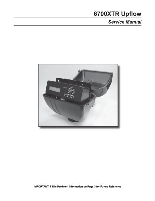
<strong>6700XTR</strong> <strong>Upflow</strong><br />
Service Manual<br />
IMPORTANT: Fill in Pertinent Information on Page 3 for Future Reference<br />
IMPORTANT: Fill in Pertinent Information on Page 3 for Future Reference
Table of Contents<br />
****Update Once Manual Finalized****<br />
IMPORTANT PLEASE READ:<br />
• The information, specifications and illustrations in this manual are based on the latest information available at the time of<br />
printing. The manufacturer reserves the right to make changes at any time without notice.<br />
• This manual is intended as a guide for service of the valve only. System installation requires information from a number of<br />
suppliers not known at the time of manufacture. This product should be installed by a plumbing professional.<br />
• This unit is designed to be installed on potable water systems only.<br />
• This product must be installed in compliance with all state and municipal plumbing and electrical codes. Permits may be<br />
required at the time of installation.<br />
• If daytime operating pressure exceeds 80 psi, nighttime pressures may exceed pressure limits. A pressure reducing valve must<br />
be installed.<br />
• Do not install the unit where temperatures may drop below 32°F (0°C) or above 125°F (52°C).<br />
• Do not place the unit in direct sunlight. Black units will absorb radiant heat increasing internal temperatures.<br />
• Do not strike the valve or any of the components.<br />
• Warranty of this product extends to manufacturing defects. Misapplication of this product may result in failure to properly<br />
condition water, or damage to product.<br />
• A prefilter should be used on installations in which free solids are present.<br />
• In some applications local municipalities treat water with Chloramines. High Chloramine levels may damage valve components.<br />
• Correct and constant voltage must be supplied to the control valve to maintain proper function.
Job Specification Sheet<br />
NOTE: Some options may not be available depending on valve model or other options chosen.<br />
Circle and/or Fill in the Appropriate Data for Future Reference.<br />
System Type:<br />
Valve Type: 56XT/6700 Proprietary C<br />
Regenerant Flow:<br />
Display Format:<br />
Unit Capacity:<br />
Water Hardness:<br />
Capacity Safety Factor: Zero or ______ %<br />
Volume Override: _________ (Gallons or M 3 )<br />
Regeneration Day Override:<br />
Regeneration Time:<br />
Meter Immediate / Time Clock Delayed / Volume Override Delayed<br />
Volume Override Immediate / Meter Delayed Weekly Reserve<br />
Meter Delayed Variable Reserve / Meter Delayed Fixed Reserve<br />
Down Flow / Up Flow / Downflow Double Backwash / Up Flow Back Wash<br />
Back Wash Filter / Up Flow Variable Flow<br />
U.S. or Metric (French Degrees, German Degrees, or PPM)<br />
_____________ Grains/French Degrees/German Degrees/PPM<br />
_____________ Grains/French Degrees/German Degrees/PPM<br />
Off or Every ______ Days<br />
Regeneration Cycle Step #1: _ _ : _ _ : _ _<br />
Regeneration Cycle Step #2: _ _ : _ _ : _ _<br />
Regeneration Cycle Step #3: _ _ : _ _ : _ _<br />
Regeneration Cycle Step #4: _ _ : _ _ : _ _<br />
Regeneration Cycle Step #5: _ _ : _ _ : _ _<br />
Media Volume:<br />
Salt Dosage:<br />
BLFC Size:<br />
Auxiliary Relay:<br />
Auxiliary Relay Start 1:<br />
Auxiliary Relay End 1:<br />
Auxiliary Relay Start 2:<br />
Auxiliary Relay End 2:<br />
Chemical Pump:<br />
Delayed _________ AM/PM or ______Immediate<br />
_________ (CuFt or Liter)<br />
_________ (lbs/CuFt or grams/Liter)<br />
_________ gpm<br />
Enabled or Disabled<br />
_ : _ _ : _ _<br />
_ : _ _ : _ _<br />
_ : _ _ : _ _<br />
_ : _ _ : _ _<br />
Enabled or Disabled<br />
CPO Aux Relay Volume: _________ (Gallons or M 3 )<br />
CPO Aux Relay:<br />
_ _ : _ _ : _ _<br />
Flow Meter Size: .75” Paddle .75” Turbine<br />
Generic Flow Meter:<br />
Maximum Flow Rate: Add _ _ Gallons every _ _ Pulses<br />
Page
General Residential Installation Check List<br />
Water Pressure<br />
A minimum of 25 lbs of water pressure is required for regeneration valve to operate effectively.<br />
Electrical Facilities<br />
An uninterrupted alternating current (A/C) supply is required. Please make sure voltage supply is compatible with<br />
unit before installation.<br />
Existing Plumbing<br />
Condition of existing plumbing should be free from lime and iron buildup. Replace piping that has heavy lime and/<br />
or iron build-up. If piping is clogged with iron, install a separate iron filter unit ahead of the water softener.<br />
Location of Softener and Drain<br />
Locate the softener close to a clean working drain and connect according to local plumbing codes.<br />
Valve Installation and Start-Up Procedures<br />
Bypass Valves<br />
1.<br />
2.<br />
3.<br />
.<br />
5.<br />
6.<br />
7.<br />
8.<br />
9.<br />
10.<br />
11.<br />
12.<br />
13.<br />
Always provide for the installation of a bypass valve if unit is not equipped with one.<br />
Place the softener tank where you want to install the unit. NOTE: Be sure the tank is level and on a firm<br />
base.<br />
During cold weather it is recommended that the installer warm the valve to room temperature before<br />
operating.<br />
Perform all plumbing according to local plumbing codes.<br />
— Use a 1/2” minimum pipe size for the drain.<br />
— Use a 3/4” drain line for backwash flow rates that exceed 7 gpm or length that exceeds 20’ (6 m).<br />
Cut the 1” distributor tube (1.050 O.D.) flush with top of each tank.<br />
Lubricate the distributor o-ring seal and tank o-ring seal. Place the main control valve<br />
on the tank. NOTE: Use only non-petroleum based silicone lubricant.<br />
Solder joints near the drain must be done before connecting the Drain Line Flow<br />
Control fitting (DLFC).<br />
Leave at least 6” (152 mm) between the DLFC and solder joints when soldering pipes<br />
that are connected on the DLFC. Failure to do this could cause interior damage to<br />
DLFC. Use only Teflon tape on the drain fitting.<br />
Be sure the floor under the salt storage tank is clean and level.<br />
With a grid plate ensure the air check fill mark is above the grid plate. With or without a<br />
grid plate, fill the brine tank with water to the mark indicated on the air check assembly.<br />
See illustration to the right.<br />
On units with a bypass, place in the bypass position.<br />
— Turn on the main water supply.<br />
— Open a cold soft water tap nearby and let water run a few minutes or until the<br />
system is free of foreign material (usually solder) resulting from the installation. Close<br />
the water tap when water runs clean.<br />
Place the bypass in the in service position and let water flow into the mineral tank.<br />
When water flow stops, slowly open a cold water tap nearby and let water run until air<br />
is purged from the unit. Then close tap.<br />
Plug the valve into an approved power source. When the valve has power it drives to<br />
the in service position.<br />
Page
Timer Operation<br />
Valve State:<br />
CHG (Change of State)<br />
CHG will be displayed when the lower drive changes from one state to another in dual piston valves.<br />
INI (Initializing)<br />
INI will display on the screen for 30 to 45 seconds when initializing after a power failure reset or programming.<br />
RGQ (Regeneration Queued)<br />
RGQ indicates that the reserve has been entered in a delayed system and regeneration has been queued.<br />
When in the main screen, press the Shift button to toggle service (SRV) with RGQ.<br />
Service (SRV)<br />
SRV will display when the unit is in service.<br />
LED Status Lights:<br />
Blue LED:<br />
Illuminates while the unit is in service and no errors exist. The unit will always be in service unless a<br />
regeneration trigger has occurred (green LED light will be displayed).<br />
Green LED:<br />
Illuminates when the unit is in Regeneration mode, unless an error condition exists.<br />
Red LED:<br />
Illuminates when there is an error.<br />
Flow Indicator:<br />
A rotating line (appearing as a rotating star shape) will display on the screen when flow is going through the<br />
the meter.<br />
Page
Timer Operation<br />
Regeneration:<br />
• A time initiated control valve regenerates when the number of programmed days has been reached<br />
• A flow initiated control valve regenerates when the volume count is zero or is below reserve<br />
capacity<br />
System Type<br />
Time Clock Delayed<br />
Meter Immediate<br />
Meter Delayed Fixed Reserve<br />
Meter Delayed Variable Reserve<br />
Meter Delayed Weekly Reserve<br />
Volume Override Immediate<br />
Volume Override Delayed<br />
Regeneration Trigger<br />
A) Day override parameter is reached and B) the time of day<br />
matches the regeneration day override time<br />
Regenerates as soon as the volume remaining has been<br />
depleted<br />
A) Volume remaining has been depleted to the fixed reserve<br />
volume and B) the regeneration time has been reached<br />
A) Volume remaining has been depleted to the variable<br />
reserve volume and B) the regeneration time has been<br />
reached<br />
A) Volume remaining has been depleted to the weekly<br />
variable reserve volume and B) the regeneration time has<br />
been reached<br />
As soon as the programmed volume remaining has been<br />
depleted from the tank<br />
As soon as soon as the programmed volume remaining has<br />
been depleted from the tank and the regeneration time has<br />
been reached<br />
Setting the Time of Day<br />
1. Press and hold the Up or Down button for 2 seconds.<br />
2. Press the Shift button to select the digit you want to modify.<br />
3. Press the Up or Down buttons to adjust the value.<br />
. Press the Extra Cycle button to return to the normal display screen, or after a 5 second timeout.<br />
NOTE: The “D” button (Diagnostic) can be pressed to exit without saving.<br />
Manually Initiating a Regeneration<br />
1. When timer is in service, press the Extra Cycle button for 5 seconds on the main screen.<br />
2. The timer advances to Regeneration Cycle Step #1, and begins programmed time count down.<br />
3. Press the Extra Cycle button once to advance valve to Regeneration Cycle Step #2 (if active).<br />
. Press the Extra Cycle button once to advance valve to Regeneration Cycle Step #3 (if active).<br />
5. Press the Extra Cycle button once to advance valve to Regeneration Cycle Step #4 (if active).<br />
6. Press the Extra Cycle button once to advance valve to Regeneration Cycle Step #5 (if active).<br />
7. Press the Extra Cycle button once more to advance the valve back to in service.<br />
NOTE: A manually initiated or queued regeneration can be cleared by pressing the Extra Cycle button for less<br />
than 5 seconds. A system queued regeneration cannot be manually cleared. If regeneration occurs for any reason<br />
prior to the delayed regeneration time, the manual regeneration request shall be cleared. Pressing the Extra Cycle<br />
button while in regeneration will cause the upper drive to advance to the next step immediately.<br />
Page
Timer Operation<br />
Queued Regeneration (RGQ)<br />
From the display screen, while the unit is in service, hold down the Extra Cycle button until “RGQ” displays. The<br />
valve will regenerate when the set regeneration time has been reached.<br />
Timer Operation During Regeneration<br />
In the main display screen, the timer shows the current regeneration cycle and the time for that step. The green<br />
LED light will display when the unit is in regeneration. Once all regeneration steps are complete, the timer returns<br />
to in service, displays a blue LED light, and resumes normal operation.<br />
Timer Operation During Programming<br />
The timer enters program mode (unit must be in service). While in the program mode the timer continues to<br />
operate normally, monitoring water usage. Timer programming is stored in memory permanently upon a normal<br />
exit from programming mode.<br />
Timer Operation During A Power Failure<br />
All program settings are stored in permanent memory. Current valve position, cycle step time elapsed, and time of<br />
day are stored during a power failure, and will be restored upon power re-application. Time is kept during a power<br />
failure, and time of day is adjusted upon power up (as long as power is restored within 12 hours).<br />
NOTE: The time of day on the main display screen will flash for 5 minutes when there has been a power outage.<br />
The flashing of the time of day can be stopped by pressing any button on the display.<br />
Regeneration Day Override Feature<br />
If the Day Override option is turned on and the valve reaches the set Regeneration Day Override value, the<br />
Regeneration Cycle starts at the programmed regeneration time.<br />
Flow Meter Equipped Timer<br />
As treated water is used, the Volume Remaining display counts down from the calculated system capacity, less<br />
the reserve volume. Once capacity reaches zero or reserve, if the immediate system the unit will regenerate<br />
immediately. If it is a Fixed, Variable, or Weekly reserve, the unit will queue a regeneration (RGQ) and count down<br />
Reserve Volume until the set regeneration time.<br />
NOTE: Reserve Volume is only available in a RGQ system.<br />
Volume Remaining<br />
(Less Reserve)<br />
Reserve<br />
Volume<br />
Page
Master Programming Mode Flow Chart<br />
NOTE: Depending on current option settings, some displays cannot be viewed or set.<br />
Entering Master<br />
Programming Mode:<br />
1. Press and hold the Shift and Set Up<br />
buttons for 5 seconds.<br />
OR<br />
2. Set the Time of Day display to 12:01 P.M.<br />
or 12:01HR (See the User Programming<br />
Section). Then go to the main display<br />
screen, press the Set Up and Set Down<br />
buttons at the same time for 5 seconds.<br />
CAUTION: Before entering Master Programming, please contact your local professional water dealer.<br />
Page
Master Programming Mode Flow Chart<br />
NOTE: Depending on current option settings, some displays cannot be viewed or set.<br />
CAUTION: Before entering Master Programming, please contact your local professional water dealer.<br />
Page
Master Programming Mode Flow Chart<br />
NOTE: Depending on current option settings, some displays cannot be viewed or set.<br />
CAUTION: Before entering Master Programming, please contact your local professional water dealer.<br />
Page 10
Master Programming Mode Flow Chart<br />
NOTE: Depending on current option settings, some displays cannot be viewed or set.<br />
CAUTION: Before entering Master Programming, please contact your local professional water dealer.<br />
Page 11
Master Programming Mode<br />
When the Master Programming Mode is entered, parameters can be set to make the timer function as needed.<br />
NOTE: Depending on current option settings, some displays cannot be viewed or set.<br />
Entering Master Programming Mode:<br />
1. Press and hold the Shift and Up buttons for 5 seconds.<br />
OR<br />
2. Set the time of day display to 12:01 PM or 12:01HR (See the User Programming section to<br />
learn how to do this). Then go to the main display screen, press the Up and Down buttons at the<br />
same time for 5 seconds.<br />
Exiting Master Programming Mode:<br />
Resets:<br />
1.<br />
1. Press the Extra Cycle button once per display until all are viewed. Master Programming Mode is<br />
exited and the normal display screen appears.<br />
2. To exit the Master Programming Mode without saving, press the Diagnostic button.<br />
NOTE: If no keypad activity is made for 5 minutes while in the Master Programming Mode, or if<br />
there is a power failure, no changes will be made, and the unit will go back to the main display<br />
screen.<br />
Soft Reset: Press and hold the Up and Down buttons for 25 seconds until 12:00PM (or 12:00HR)<br />
appears. This resets all parameters except for the flow meter totalizer volume.<br />
Master Reset: Hold the Extra Cycle button while powering up the unit. This resets all of the<br />
parameters in the unit. Check and verify the choices selected in Master Programming Mode.<br />
System Type<br />
This program step selects the system type.<br />
— Press the Up or Down buttons to adjust this value.<br />
— Press the Extra Cycle button.<br />
2.<br />
Valve Type<br />
This program step selects the valve type.<br />
— Press the Up or Down buttons to adjust this value.<br />
— Press the Extra Cycle button.<br />
CAUTION: Before entering Master Programming, please contact your local professional water dealer.<br />
Page 12
Master Programming Mode<br />
3.<br />
Regenerant Flow<br />
This program step selects how the regenerant flows through the tank (must match cam). The selections<br />
available will vary depending on the previously chosen valve model.<br />
— Press the Up or Down buttons to adjust this value.<br />
— Press the Extra Cycle button.<br />
4.<br />
Display Format<br />
This program step selects the display format.<br />
— Press the Up or Down buttons to adjust this value.<br />
— Press the Extra Cycle button.<br />
5.<br />
Unit Capacity<br />
This program step selects the timer’s total capacity of hardness that can be removed.<br />
— Press the Shift button to select the digit you want to modify.<br />
— Press the Up or Down buttons to adjust this value.<br />
— Press the Extra Cycle button.<br />
6.<br />
Feed Water (Hardness)<br />
This program step is used to set the feed water hardness. The system will automatically calculate volume<br />
remaining based on the unit capacity, capacity safety factor (reserve systems only), and feed water hardness<br />
entered.<br />
— Press the Shift button to select the digit you want to modify.<br />
— Press the Up or Down buttons to adjust this value.<br />
— Press the Extra Cycle button.<br />
CAUTION: Before entering Master Programming, please contact your local professional water dealer.<br />
Page 13
Master Programming Mode<br />
1.<br />
Capacity Safety Factor<br />
This program step is used to set the reserve capacity of the unit. This is a percentage by which the unit’s<br />
capacity is reduced.<br />
— Press the Shift button to select the digit you want to modify.<br />
— Press the Up or Down buttons to adjust this value.<br />
— Press the Extra Cycle button.<br />
2.<br />
3.<br />
Volume Override<br />
This program step is used to set the volume override of the unit.<br />
— Press the Shift button to select the digit you want to modify.<br />
— Press the Up or Down buttons to adjust this value.<br />
— Press the Extra Cycle button.<br />
Regeneration Day Override<br />
This program step sets the maximum amount of time (in days) the unit can be in service without a<br />
regeneration.<br />
— Press the Shift button to select the digit you want to modify.<br />
— Press the Up or Down buttons to adjust this value.<br />
— Press the Extra Cycle button.<br />
4.<br />
Regeneration Time<br />
This program step sets the time of day for the regeneration to occur in delayed systems.<br />
— Press the Shift button to select the digit you want to modify.<br />
— Press the Up or Down buttons to adjust this value.<br />
— Press the Extra Cycle button.<br />
CAUTION: Before entering Master Programming, please contact your local professional water dealer.<br />
Page 14
Master Programming Mode<br />
5.<br />
Regeneration Cycle Step Programming<br />
This program step programs the Regeneration Cycle step times 1 through 5. Please refer to the chart below<br />
for regenerant flow default cycle steps and times.<br />
Regenerant Flow Cycle 1 Time Cycle 2 Time Cycle 3 Time Cycle 4 Time Cycle 5 Time<br />
Down Flow<br />
Back Wash<br />
10<br />
Minutes<br />
Brine<br />
& Slow<br />
Rinse<br />
1 Hour<br />
Rapid<br />
Rinse<br />
10<br />
Minutes<br />
Brine Tank Fill 12 Minutes N/A N/A<br />
Back Wash Filter<br />
Back Wash<br />
15<br />
Minutes<br />
Draw 0<br />
Settling<br />
Rinse<br />
10<br />
Minutes<br />
Refill 0 N/A N/A<br />
UF Back Wash<br />
Backwash<br />
10<br />
Minutes<br />
Brine<br />
& Slow<br />
Rinse<br />
1 Hour<br />
Rapid<br />
Rinse<br />
10<br />
Minutes<br />
Brine Tank Fill 12 Minutes N/A N/A<br />
Down Flow Double<br />
Backwash<br />
Back Wash<br />
10<br />
Minutes<br />
Brine<br />
& Slow<br />
Rinse<br />
1 Hour<br />
Back<br />
Wash<br />
10<br />
Minutes<br />
Rapid Rinse 10 Minutes Brine Tank Fill 12 Minutes<br />
Up Flow Brine Rinse 60<br />
Back<br />
Wash<br />
10<br />
Rapid<br />
Rinse<br />
10<br />
Minutes<br />
Brine Tank Fill 12 Minutes N/A N/A<br />
<strong>Upflow</strong> Variable Fill Brine Rinse Variable Pause<br />
60<br />
minutes<br />
Brine<br />
Rinse<br />
60<br />
Minutes<br />
Back Wash 12 Minutes Rapid Rise 10 Minutes<br />
6.<br />
7.<br />
8.<br />
9.<br />
Media Volume<br />
This program step sets the volume of the media in the resin tank.<br />
— Press the Shift button to select the digit you want to modify.<br />
— Press the Up or Down buttons to adjust this value.<br />
— Press the Extra Cycle button.<br />
Salt Dosage<br />
This program step sets the salt dosage in the unit.<br />
— Press the Shift button to select the digit you want to modify.<br />
— Press the Up or Down buttons to adjust this value.<br />
— Press the Extra Cycle button.<br />
Brine Line Flow Control Size<br />
This program step allows the selection of the desired brine line flow control size in the unit (must match<br />
physical brine line flow control).<br />
— Press the Up or Down buttons to adjust this value.<br />
— Press the Extra Cycle button.<br />
Auxiliary Relay Output<br />
The next two displays are part of a series of settings used to program the optional relay output. The first<br />
setting turns the output on/off during regeneration only. The second turns the output on during service only,<br />
every time a set volume of water used has accumulated.<br />
NOTE: When auxiliary outputs are in the OFF (default) setting, press the Up or Down buttons to set<br />
CAUTION: Before entering Master Programming, please contact your local professional water dealer.<br />
Page 15
Master Programming Mode<br />
1.<br />
the first setting. Then press the Extra Cycle button to advance to the second setting.<br />
a. Timed Auxiliary Relay Output Window (Start & End Time Setting)<br />
This option setting consists of two displays. The first display sets the turn-on time of the output, referenced<br />
to the start of the first regeneration cycle. The second display sets the output turn-off time, referenced again<br />
to the start of the first regeneration cycle. An OFF setting cancels this setting. All settings are in minutes and<br />
output timing is synchronized with regeneration cycle timing.<br />
Start Time: Any time during regeneration.<br />
End Time: At start time, and anytime during the regeneration cycle.<br />
b. Chemical Pump Auxiliary Relay Output Window<br />
This option setting consists of two displays. The first display sets the volume of water flow at which the output<br />
turns on. The second display sets the on time (in seconds) of the output.<br />
— Activate output after volume set is reached.<br />
— Press the Shift button to select the digit you want to modify.<br />
— Press the Up or Down buttons to adjust this value.<br />
— Press the Extra Cycle button.<br />
2.<br />
Flow Meter Size<br />
This program step sets the size of the flow meter.<br />
— Press the Up or Down buttons to adjust this value.<br />
— Press the Extra Cycle button.<br />
3.<br />
4.<br />
5.<br />
Maximum Flow Rate<br />
This program step sets maximum flow rate of the generic flow meter.<br />
— Press the Shift button to select the digit you want to modify.<br />
— Press the Up or Down buttons to adjust this value.<br />
— Press the Extra Cycle button.<br />
Pulses per Gallon/Liter<br />
This program step sets the pulses per gallon/liter for generic flow meters.<br />
— Press the Shift button to select the digit you want to modify.<br />
— Press the Up or Down buttons to adjust this value.<br />
— Press the Extra Cycle button.<br />
End of Master Programming Mode<br />
CAUTION: Before entering Master Programming, please contact your local professional water dealer.<br />
Page 16
User Programming Mode & Flow Chart<br />
NOTE: Depending on current option settings, some displays cannot be viewed or set.<br />
Entering User Mode:<br />
Press and hold the Up and Down<br />
buttons for 5 seconds.<br />
NOTE: Depending on current option settings, some displays cannot be viewed or set.<br />
1.<br />
2.<br />
3.<br />
4.<br />
5.<br />
Enter User Mode<br />
— Press and hold the Up and Down buttons for 5 seconds.<br />
Set Feed Water Hardness<br />
— Press the Shift, Up, and Down buttons to move the cursor and change the value of the numbers.<br />
— Press the Extra Cycle button to proceed to the next step.<br />
NOTE: Only displayed when a metered option is chosen under System Type.<br />
Set Regeneration Day Override<br />
— To turn on and set the days, press the Down button.<br />
— Press the Shift, Up, and Down buttons to move the cursor and change the value of the numbers.<br />
— Press the Extra Cycle button to proceed to the next step.<br />
Regeneration Time<br />
— Press the Shift, Up, and Down buttons to move the cursor and change the value of the numbers.<br />
— Press the Extra Cycle button<br />
End of User Programming Mode<br />
Page 17
Diagnostic Programming Mode Flow Chart<br />
NOTE: Depending on current option settings, some displays cannot be viewed or set.<br />
Entering Diagnostic Mode:<br />
1.<br />
2.<br />
3.<br />
.<br />
Press and release the “D” button.<br />
Press the Extra Cycle button once per<br />
display until all displays are viewed and the<br />
normal display screen appears.<br />
Press and release the “D” button during this<br />
mode to exit the Diagnostic Mode.<br />
Depending on current option settings, some<br />
displays cannot be viewed.<br />
Page 18
Diagnostic Programming Mode<br />
NOTE: Depending on current option settings, some displays cannot be viewed.<br />
Overview Diagnostic Mode<br />
The current Diagnostic Programming Mode screen will display until either the Extra Cycle button is pressed<br />
through for each screen, or the Diagnostic button is pressed. In the event of regeneration occurring while in the<br />
Diagnostic Programming Mode, the regeneration step and time remaining will be displayed. When regeneration<br />
completes, the display will return to the normal time of day display screen.<br />
Entering and Exiting Diagnostic Mode<br />
Press and release the “D” button to enter the Diagnostic Programming Mode. Pressing the Extra Cycle button will<br />
move to the next diagnostic screen. Press the Extra Cycle button once per display until all are viewed. Pressing<br />
the Diagnostic button while in Diagnostic Mode will cause the unit to leave the Diagnostic Mode and return to the<br />
normal time of day display screen.<br />
1.<br />
2.<br />
3.<br />
4.<br />
5.<br />
6.<br />
7.<br />
8.<br />
9.<br />
Current Flow Rate<br />
This program step displays the calculated flow rate for the timer. The below flow rates are the maximum flow<br />
rate the timer will read for each meter.<br />
.75” Paddle: 15 gpm (0.06 m3/m) .75” Turbine: 15 gpm (0.06 m3/m)<br />
— Press the Extra Cycle button.<br />
Peak Flow Rate<br />
This program step displays the peak flow rate since the last regeneration.<br />
— Press the Extra Cycle button.<br />
Totalizer<br />
This program step displays the total volume of treated water that passes through the meter.<br />
— Reset to zero by holding the Up and Down buttons for five seconds while in the totalizer screen.<br />
— Press the Extra Cycle button.<br />
Hours Between Last Two Regenerations<br />
This program step displays the time between the last two regenerations saved.<br />
— Press the Extra Cycle button.<br />
Hours Since Last Regeneration<br />
This program step displays the hours since the last regeneration.<br />
— Press the Extra Cycle button.<br />
Volume Remaining<br />
This program step displays the volume remaining. The timer will regenerate if the volume remaining is set to<br />
zero. The maximum ranges are the same as the maximum volume calculated on the main screen.<br />
— Press the Extra Cycle button.<br />
Reserve Capacity<br />
This program step displays the reserve capacity, ensuring soft water is available at all times.<br />
— Press the Extra Cycle button.<br />
Previous Day’s Water Usage<br />
This program step displays the previous day’s water usage.<br />
— Press the Extra Cycle button.<br />
Software Version<br />
This program step displays the timer’s software program version number.<br />
— Press the Extra Cycle button to exit.<br />
NOTE: Diagnostic Programming Mode will stop if the system goes into a regeneration.<br />
Page 19
6700 Powerhead Assembly<br />
61501-6700_REVC<br />
Page 20
6700 Power Head Assembly<br />
Item No. Quantity Part No. Description<br />
1..................1....................15494-04.................Drive Panel Assy, 6700<br />
2..................1....................17844.......................Bracket, Support, 6700<br />
3..................1....................13299.......................Washer, Spring, 3/8<br />
4..................1....................13017.......................Gear, Idler<br />
5..................1....................23045.......................Gear, Drive, 6700<br />
6..................1....................13175.......................Plate, Motor Mounting<br />
7..................2....................19080.......................Spring, Compression, 6700<br />
8..................2....................13300.......................Ball, 1/4” SS<br />
9..................2....................13296.......................Screw, Hex Wsh, 6-20 x 1/2<br />
10................1....................25005-10.................Gear, Main Drive, ET, SE<br />
11................1....................18722.......................Cam, Brine Valve, 6600/6700, Blk<br />
19025.......................Cam, Brine Valve, Variable<br />
12................1....................12037.......................Washer, Plain, #10<br />
13................1....................40214.......................Screw, Hex Wsh, 6-20 x 3/4<br />
14................2....................18754.......................Pin, 6700<br />
15................1....................19079.......................Washer, Friction<br />
16................1....................17438.......................Cam, 6600, Downflow<br />
4 0609.......................Cam, Double Backwash, D/F<br />
17919.......................Cam, Variable Brining, Gray<br />
17................1....................15151.......................Screw, Flat Head St, 6-20 x 3/4<br />
18................2....................10218.......................Switch, Micro<br />
19................1....................10302.......................Insulator, Limit Switch<br />
20................2....................17876.......................Screw, Phil Pan, 4-40 x 1 1/8<br />
21................1....................17841-XXX..............Cover, Bottom, 6700<br />
22................1....................13547.......................Strain Relief, Flat Cord<br />
23................1....................16944.......................Motor Drive, 24V, 60 Hz, 2RPM<br />
24................3....................11384.......................Screw, Phil, 6-32 x 1/4<br />
25................4....................17798.......................Screw, Slot Hex Hd<br />
26................2....................12473.......................Screw, Hex Wsh, 10-24 x 5/8<br />
27................1....................17845.......................Pin, Hinge, 6700<br />
28................1....................18679.......................Cap, Tapered, Black<br />
29................1....................17842-XX.................Cover, Top 6700<br />
30................1....................18615.......................Seal, Neoprene, .125<br />
31................1....................19674.......................Transformer, 24V, 9.6VA, Residential Valves<br />
4 1475.......................Transformer, 24V, 9.6VA, European<br />
32................1....................42115.......................Harness Assy, 5066/6600/6700<br />
33................1....................19313-XX.................Circuit Board Housing Assy<br />
Page 21
Control Valve Assembly<br />
61500-6600-6700_UF_REVB<br />
Page 22
Control Valve Assembly<br />
Item No. Quantity Part No. Description<br />
1.........................1............................19707-30............................ Valve Body, 5600 <strong>Upflow</strong>, Bayonet<br />
2.........................1............................13255................................. Clip, Mounting<br />
3.........................5............................13242................................. Seal, 5600<br />
4.........................1............................13304................................. O-ring, -121<br />
5.........................1............................12281................................. O-ring, -338<br />
6.........................4............................14241................................. Spacer, 5600<br />
7.........................1............................14309................................. Retainer, Piston Rod<br />
8.........................1............................13030................................. Retainer, Dist Tube, O-ring<br />
9.........................3............................12112................................. Screw, Hex Hd Mach, 10-24 x 1/2<br />
10.......................1............................13302................................. O-ring, -014<br />
11.......................1............................10913-XX........................... Nozzle, Injector (specify size)<br />
12.......................1............................10914-XX........................... Throat, Injector (specify size)<br />
13.......................1............................11973................................. Spring, Brine Valve<br />
14.......................1............................11981-01............................ Ring, Retaining<br />
15.......................1............................12088................................. Washer, Flow 2.4 GPM<br />
16.......................1............................12550................................. Quad Ring, -009<br />
17.......................1............................12626................................. Seat, Brine Valve<br />
18.......................1............................12638................................. O-ring, -013, Injector<br />
19.......................1............................12977................................. O-ring, -015<br />
20.......................1............................13163................................. Body, Injector<br />
21.......................1............................13165................................. Cap, Brine Valve<br />
22.......................1............................13167................................. Spacer, Brine Valve<br />
23.......................1............................13172................................. Brine Valve Stem<br />
24.......................1............................13173................................. Retainer, DLFC Button<br />
25.......................1............................13244................................. Adapter, BLFC<br />
26.......................1............................13245................................. Retainer, BLFC<br />
27.......................2............................13301................................. O-ring, -011, Injector<br />
28.......................1............................13303................................. O-ring, -021<br />
29.......................1............................13497................................. Disperser, Air, 5600<br />
30.......................1............................15348................................. O-ring, -563<br />
31.......................1............................16098................................. Washer, Nylon Brine<br />
32.......................1............................13302-01............................ O-ring, -014, 560CD<br />
33.......................1............................13296................................. Screw, Hex Wsh, 6-20 x 1/2<br />
34.......................2............................13314................................. Screw, Slot Ind Hex, 8-18 x .60<br />
35.......................1............................13363................................. Washer, Plain, .145 ID SS<br />
36.......................1............................13546................................. Retainer, End Plug<br />
37.......................2............................19228................................. Coupling, Adapter<br />
38.......................4............................13305................................. O-ring, -119<br />
39.......................1............................14067................................. Adapter, <strong>Upflow</strong> Brine<br />
40.......................1............................15449................................. Body, Regulator<br />
41.......................1............................14851................................. Cap, Regulator<br />
42.......................1............................17307................................. Washer, Flow, .125 gpm<br />
43.......................2............................15607................................. Screw, Hex Hd Mach, 10-24 x 1 3/8<br />
44.......................1............................15548................................. Screen, Pressure Regulator<br />
45.......................1............................23391................................. Seat, Regulator Spring<br />
46.......................1............................23393................................. Poppet, Regulator<br />
47.......................1............................14850................................. Spring, Compression<br />
48.......................1............................14846................................. Washer, Pressure Regulator<br />
49.......................1............................14847................................. Diaphragm, Regulator<br />
50.......................1............................14848................................. Ring, Slip, Regulator, SS<br />
51.......................1............................24602................................. Link, Piston Rod<br />
52.......................1............................15558................................. Rod, Piston, <strong>Upflow</strong><br />
53A....................1............................41026-01............................ Yoke, 1”, NPT, Cast, Machd, SS<br />
4 1027-01............................ Yoke, 3/4”, NPT, Cast, Machd<br />
53B....................1............................18706................................. Yoke, 1”, NPT, Plastic<br />
18706-02............................ Yoke, 3/4”, NPT, Plastic<br />
Not Shown:<br />
1............................12638................................. O-ring, -013, Injector<br />
1............................12626................................. Seat, Brine Valve<br />
1............................14613................................. Flow Straightener<br />
1............................14846................................. Washer, Pressure Regulator<br />
1............................14847................................. Diaphragm, Regulator<br />
1............................14848................................. Ring, Slip, Regulator SS<br />
1............................14850................................. Spring, Compresssion<br />
1............................14851................................. Cap, Regulator<br />
1............................15449................................. Body, Regulator<br />
1............................23391................................. Seat, Regulator Spring<br />
1............................23393................................. Poppet, Regulator<br />
1............................15548................................. Screen, Pressure Regulator<br />
2............................15607................................. Screw, Hex Hd Mach, 10-24 x 1 3/8<br />
Page 23
Meter Assembly<br />
60086_REVD_60086-50<br />
Item No. Quantity Part No. Description<br />
1..................1....................13874.......................Cap, Meter, Electronic<br />
2..................1....................14715.......................Gear Assy, Electronic Meter Cap<br />
3..................1....................41055.......................Plate, Intermediate<br />
4..................1....................13847.......................O-ring, -137, Std, Meter<br />
5..................5....................17798.......................Screw, Slot Hex Wsh Hd<br />
6..................1....................13821.......................Body, Meter, 5600<br />
7..................1....................13509.......................Impeller, Meter<br />
8..................4....................12473.......................Screw, Hex Wsh, 10-24 x 5/8<br />
9..................4....................13255.......................Clip, Mounting<br />
10................4....................13314.......................Screw, Slot Ind Hex, 8-18 x .60<br />
11................4....................13305.......................O-ring, -119<br />
12................1....................14613.......................Flow Straightener<br />
Page 24
Bypass Valve Assembly, Non-Metallic<br />
60049_REVD<br />
Item No. Quantity Part No. Description<br />
1..................2....................13305.......................O-ring, -119<br />
2..................2....................13255.......................Clip, Mounting<br />
3..................2....................13314.......................Screw, Slot Ind Hex, 8-18 x .60<br />
4A................1....................18706.......................Yoke, 1”, NPT, Plastic<br />
18706-02.................Yoke, 3/4”, NPT, Plastic<br />
4B................1....................41027-01.................Yoke, 3/4”, NPT, Cast, Machd<br />
4 1026-01.................Yoke, 1”, NPT, Cast, Machd, SS<br />
Page 25
Bypass Valve Assembly, Brass<br />
60040SS_REVL 60041_REVK<br />
Item No. Quantity Part No. Description<br />
1..................1....................40614.......................By-pass Body, 3/4”<br />
4 0634.......................By-pass Body, 1”, SS<br />
2..................1....................14105.......................Seal, By-pass, 560CD<br />
3..................1....................11972.......................Plug, By-pass<br />
4..................1....................11978.......................Plate, By-pass, Top<br />
5..................1....................11979-02..................Lever, By-pass, Black<br />
6..................1....................11986.......................Plate, By-pass, Bottom<br />
7..................8....................15727.......................Screw, Hex Wsh Hd, 10-24 x 1/2<br />
8..................1....................13604-03.................Label, By-pass, Standard Mount<br />
13604-04.................Label, By-pass, Reverse Mount, Blue<br />
9..................1....................40974.......................Washer, Plain, 3/8”<br />
10................1....................40973.......................Screw, Phil Hd, Indented Hex Hd 1/4-14 x .50<br />
Page 26
2300 Safety Brine Valve<br />
60027_REVA<br />
Item No. Quantity Part No. Description<br />
1..................1....................60027-00.................Safety Brine Valve, 2300 Less Elbow<br />
2..................1....................10138.......................Ball, 3/8” Brass<br />
3..................1....................11566.......................Ball Stop, Slow-Fill<br />
4..................1....................10328.......................Fitting, Elbow, 90 Deg. 1/4 NPT x 3/8 T<br />
5..................2....................10332.......................Fitting, Insert, 3/8<br />
6..................2....................10330.......................Fitting, Sleeve, 3/8 Celcon<br />
7..................2....................10329.......................Fitting, Tube, 3/8 Nut, Brass<br />
8..................1....................10186.......................Nut, Hex, 10-32 Nylon<br />
9..................1....................60002.......................Air Check, #500<br />
10................1....................10149.......................Rod, Float<br />
11................1....................10700.......................Float Assy, Blue/White<br />
12................4....................10150.......................Grommet, .30 Dia.<br />
Page 27
2310 Safety Brine Valve<br />
42112_REVA<br />
Item No. Quantity Part No. Description<br />
1..................1....................19645.......................Body, Safety Brine Valve, 2310<br />
2..................1....................19803.......................Safety Brine Valve, Arm Assy<br />
3..................1....................19804.......................Screw, Sckt Hd, Set, 10-24 x .75<br />
4..................1....................19805.......................Nut, Hex, 10-24, Nylon Black<br />
5..................1....................19652-01.................Poppet Assy, SBV w/o O-ring<br />
6..................1....................19649.......................Flow Dispenser<br />
7..................1....................11183.......................O-ring, -017<br />
8..................1....................19647.......................Elbow, Safety Brine Valve<br />
9..................2....................19625.......................Nut Assy, 3/8” Plastic<br />
10................1....................18312.......................Retainer, Drain<br />
11................1....................60014.......................Safety Brine Valve Assy, 2310 (includes items 1-10)<br />
12................2....................10150.......................Grommet, .30 Dia (included with item 13)<br />
13................1....................60068.......................Float Assy, 2310, w/30” Rod<br />
14................1....................60002.......................Air Check, #500<br />
Page 28
Troubleshooting - Timer<br />
If an error is detected, an error screen will alternate with the main display screen every few seconds, and the LED<br />
light will be red.<br />
During an error condition, the unit continues to monitor the flow meter and update the remaining capacity.<br />
Once an error condition is corrected, the unit returns to the operating status it was in prior to the error, and<br />
regeneration resumes according to normal programming. If an error is cleared by reprogramming the unit in<br />
the Master Programming Mode, the volume remaining may be reset to the full unit capacity (as though it had<br />
just regenerated). If an error is present, a regeneration can only occur manually by pressing and holding the<br />
Extra Cycle button for 5 seconds. If the unit was in regeneration when the error occurred, it will complete the<br />
regeneration cycle and go into service.<br />
When the problem is corrected, and the error no longer displays (it may take several seconds for the unit to stop<br />
displaying the error message), the unit will return to normal operation. The LED light will no longer be red, and<br />
will turn Green if the unit is regenerating, or Blue if the unit is in service.<br />
Problem<br />
Correction<br />
A. Flashing/blinking display A. Power outage has occurred. Either wait 5 minutes for<br />
blinking to stop, or press any key on the keypad.<br />
B. Unit not responding after going into<br />
regeneration<br />
C. Unit displays “ERROR CODE: REPLACE<br />
UNIT” (corrupted UAP)<br />
B. Verify the unit is configured correctly (ex: wiring valve type).<br />
Perform a Master Reset by holding the Extra Cycle button and<br />
cycling power. Check and verify the choices selected in Master<br />
Programming Mode.<br />
C. Contact your local water treatment professional.<br />
Error Codes<br />
Error<br />
Code<br />
Display Message<br />
01 ERROR CODE:<br />
PROGRAM UNIT<br />
02 ERROR CODE:<br />
PROGRAM UNIT<br />
03 ERROR CODE:<br />
SERVICE UNIT<br />
04 ERROR CODE:<br />
SERVICE UNIT<br />
05 ERROR CODE:<br />
SERVICE UNIT<br />
Correction<br />
Go through all screens in Master Programming Mode.<br />
Go through all screens in Master Programming Mode.<br />
Perform a Master Reset by holding the Extra Cycle button and cycling power.<br />
Go through all screens in Master Programming Mode. Manually initiate a<br />
regeneration cycle by pressing the Extra Cycle button for 5 seconds.<br />
Perform a Master Reset by holding the Extra Cycle button and cycling power.<br />
Go through all screens in Master Programming Mode. Manually initiate a<br />
regeneration cycle by pressing the Extra Cycle button for 5 seconds.<br />
Call your local water treatment professional as soon as possible. Leave the unit<br />
running (do not unplug).<br />
NOTE: If the above corrections do not work, please contact your local water treatment professional.<br />
Error Display Screen Examples<br />
Page 29
Troubleshooting - Control Valve<br />
Problem Cause Correction<br />
1. Water conditioner fails to<br />
regenerate.<br />
A. Electrical service to unit has<br />
been interrupted<br />
B. Timer is defective. B. Replace timer.<br />
A. Assure permanent electrical service<br />
(check fuse, plug, pull chain, or switch)<br />
C. Power failure. C. Reset time of day.<br />
2. Hard water. A. By-pass valve is open. A. Close by-pass valve.<br />
B. No salt is in brine tank. B. Add salt to brine tank and maintain<br />
salt level above water level.<br />
C. Injector screen plugged. C. Clean injector screen.<br />
D. Insufficient water flowing into<br />
brine tank.<br />
D. Check brine tank fill time and clean<br />
brine line flow control if plugged.<br />
E. Hot water tank hardness. E. Repeated flushings of the hot water<br />
tank is required.<br />
F. Leak at distributor tube. F. Make sure distributor tube is not<br />
cracked. Check O-ring and tube pilot.<br />
G. Internal valve leak. G. Replace seals and spacers and/or<br />
piston.<br />
3. Unit used too much salt. A. Improper salt setting. A. Check salt usage and salt setting.<br />
B. Excessive water in brine tank. B. See problem 7.<br />
4. Loss of water pressure. A. Iron buildup in line to water<br />
conditioner.<br />
5. Loss of mineral through drain<br />
line.<br />
B. Iron buildup in water<br />
conditioner.<br />
C. Inlet of control plugged due<br />
to foreign material broken loose<br />
from pipes by recent work done on<br />
plumbing system.<br />
A. Clean line to water conditioner.<br />
B. Clean control and add mineral cleaner<br />
to mineral bed. Increase frequency of<br />
regeneration.<br />
C. Remove piston and clean control.<br />
A. Air in water system. A. Assure that well system has proper<br />
air eliminator control. Check for dry well<br />
condition.<br />
B. Improperly sized drain line flow<br />
control.<br />
B. Check for proper drain rate.<br />
6. Iron in conditioned water. A. Fouled mineral bed. A. Check backwash, brine draw, and<br />
brine tank fill. Increase frequency of<br />
regeneration. Increase backwash time.<br />
7. Excessive water in brine<br />
tank.<br />
A. Plugged drain line flow control. A. Clean flow control.<br />
B. Plugged injector system. B. Clean injector and screen.<br />
C. Timer not cycling. C. Replace timer.<br />
D. Foreign material in brine valve. D. Replace brine valve seat and clean<br />
valve.<br />
E. Foreign material in brine line<br />
flow control.<br />
E. Clean brine line flow control.<br />
Page 30
Troubleshooting - Control Valve<br />
Problem Cause Correction<br />
8. Softener fails to draw brine. A. Drain line flow control is<br />
plugged.<br />
A. Clean drain line flow control.<br />
B. Injector is plugged. B. Clean injector<br />
C. Injector screen plugged. C. Clean screen.<br />
D. Line pressure is too low. D. Increase line pressure to 20 P.S.I.<br />
E. Internal control leak E. Change seals, spacers, and piston<br />
assembly.<br />
F. Service adapter did not cycle. F. Check drive motor and switches.<br />
9. Control cycles continuously. A. Misadjusted, broken, or shorted<br />
switch.<br />
10. Drain flows continuously. A. Valve is not programming<br />
correctly.<br />
A. Determine if switch or timer is faulty<br />
and replace it, or replace complete<br />
power head.<br />
A. Check timer program and positioning<br />
of control. Replace power head assembly<br />
if not positioning properly.<br />
B. Foreign material in control. B. Remove power head assembly and<br />
inspect bore. Remove foreign material<br />
and check control in various regeneration<br />
positions.<br />
C. Internal control leak. C. Replace seals and piston assembly.<br />
General Service Hints For Meter Control<br />
Problem: Softener delivers hard water<br />
Reason: Reserve capacity has been exceeded.<br />
Correction: Check salt dosage requirements and reset program wheel to provide additional reserve.<br />
Reason: Meter is not measuring flow.<br />
Correction: Check meter with meter checker.<br />
Page 31
Water Conditioner Flow Diagrams<br />
Service Position (Yellow, Red, & Gray Cams)<br />
Backwash Position (Yellow & Red Cams)<br />
Page 32
Water Conditioner Flow Diagrams<br />
Brine/Slow Rinse Position (Regeneration Cycle Step #1, Red Cam)<br />
Brine/Slow Rinse Position (Regeneration Step #2, Yellow Cam)<br />
Page 33
Water Conditioner Flow Diagrams<br />
Brine Making Position (Regeneration Cycle Step #2, Gray Cam)<br />
Brine/Slow Rinse Position (Regeneration Cycle Step #3, Gray Cam)<br />
Page 34
Water Conditioner Flow Diagrams<br />
Rapid Rinse Position (Regeneration Step #3, Yellow, Red, & Gray Cams)<br />
Brine Tank Fill Position (Regeneration Cycle Step #4, Red Cam)<br />
Page 35
Water Conditioner Flow Diagrams<br />
Backwash Position (Regeneration Cycle Step #4, Gray Cam)<br />
Brine Tank Fill Position (Regeneration Cycle Step #4, Yellow & Gray Cams)<br />
Page 36
Valve Wiring Diagram<br />
42139_REVA<br />
Page 37
Service Assemblies<br />
Air Check:<br />
60002-34......... Air Check, #500, 34” Long<br />
Brine Line Flow Control:<br />
60022-12......... BLFC, .125 GPM, 5000/5600/9000<br />
60022-25......... BLFC, .25 GPM, 5000/5600/9000<br />
60022-50......... BLFC, .50 GPM, 5000/5600/9000<br />
60022-100....... BLFC, 1.0 GPM, 5000/5600/9000<br />
17307.............. Washer, Flow, .125 GPM<br />
12094.............. Washer, Flow, .25 GPM<br />
12095.............. Washer, Flow, .50 GPM<br />
12097.............. Washer, Flow, 1.0 GPM<br />
12977.............. O-ring, -015<br />
13244.............. Adapter, BLFC<br />
13245.............. Retainer, BLFC<br />
60032.............. Brine Valve, 4600/5600<br />
Bypass:<br />
60040SS......... Bypass Assy, 3/4” NPT SS<br />
60041SS......... Bypass Assy, 1” NPT SS<br />
60049.............. Bypass Plastic Assy<br />
Control Valve:<br />
11973.............. Spring, Brine Valve<br />
11981-01......... Ring, Retaining<br />
12550.............. Quad Ring, -009<br />
13165.............. Cap, Brine Valve<br />
13167.............. Spacer, Brine Valve<br />
13302.............. O-ring, -014<br />
16098.............. Washer, Nylon Brine<br />
13172.............. Brine Valve Stem<br />
12626.............. Seat, Brine Valve<br />
Floats:<br />
60028-XX........ 2300 Blue/White Float<br />
60068-XX........ 2310 Blue/White Float<br />
Injector:<br />
60084-XX........ Injector, Module Assembly<br />
Meter:<br />
60086-50......... Meter Assy, 3/4”, Electronic<br />
Pistons:<br />
60102-62......... Piston Assy, 6600/6700, <strong>Upflow</strong><br />
14309.............. Retainer, Piston Rod<br />
13001-03......... Piston Rod Assy, 6600, <strong>Upflow</strong><br />
15561.............. End Plug Assy, 6600<br />
18848.............. Piston, 6600, <strong>Upflow</strong><br />
Powerhead:<br />
60751-121....... Panel, 6600, Front, 24V, Black<br />
Safety Brine Valve:<br />
60014.............. 2310 Safety Brine Valve Assy<br />
60027-FFA...... 2300 Safety Brine Valve Assy<br />
60027-FFS...... 2300 Safety Brine Valve Assy<br />
Seal & Spacer Kit:<br />
60125.............. Seal & Spacer Kit, 5600/9000 Top<br />
13242.............. Seal, 5600<br />
14241.............. Spacer, 5600<br />
Timer:<br />
42274.............. Assy, XTR Timer, 6700<br />
Yokes:<br />
18706.............. Yoke, 1”, NPT, Plastic<br />
18706-02......... Yoke, 3/4”, NPT, Plastic<br />
41026-01......... Yoke, 1”, NPT, SS<br />
41027-01......... Yoke, 3/4” NPT<br />
Page 38
Notes<br />
Page 39
Notes<br />
Page 40
Notes<br />
Page 41
Notes<br />
Page 42
Notes<br />
Page 43
P/N 42134<br />
Rev. A