THE NAVAL ENGINEER
THE NAVAL ENGINEER
THE NAVAL ENGINEER

You also want an ePaper? Increase the reach of your titles
YUMPU automatically turns print PDFs into web optimized ePapers that Google loves.
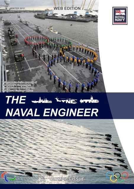
WINTER 2012<br />
WEB EDITION<br />
This magazine is the property of<br />
Her Majesty’s Government.<br />
It is produced on behalf of the<br />
Chief Naval Engineer Officer.<br />
<strong>THE</strong><br />
<strong>NAVAL</strong> <strong>ENGINEER</strong><br />
OLYMPICS ISSUE
<strong>THE</strong> <strong>NAVAL</strong> <strong>ENGINEER</strong><br />
Contents<br />
Editorial Board, Editor’s Corner ............................................................................................................ 1<br />
London 2012 – Engineers and Engineering ................................................................................................ 2<br />
Cutting Edge Integration Facility Opens By the Editor ........................................................................ 12<br />
Innovative All-Electric Launch Solution for Future Electric Submarine By Daniel Pettitt ..................... 14<br />
The Eastney Microwave “Oven” ........................................................................................................... 17<br />
Who is MCTA? By Lt M.J. Hawkes ...................................................................................................... 18<br />
Optimising Fleet Fuel Usage – Hull Review By Steve Marshall .......................................................... 22<br />
HMS Albion Achieving Extended Readiness By WO1 S.M. Southern and Andrew Davies ................ 26<br />
Mobile Phone Technology in a Clockwork World ................................................................................. 31<br />
The Re-Invigoration of ME Officers’ Training By Lt P.A. Still ............................................................... 32<br />
‘The Engineers’ – Frustrating RN Golfers since 1994 By ex-CMEM(M) M. Williams ................................ 34<br />
ITIL Never Work! By Lt D.N. Nyugo ............................................................................................................ 36<br />
Growing Royal Navy Engineering Technicians of the Future By Lt Cdr P.C. O’Shaughnessy ........................ 39<br />
Armourers and Brasiers Medal ......................................................................................................................... 43<br />
Naval Engineering – Lessons Identified ............................................................................................... 44<br />
• The magazine is published for information, entertainment and to promote discussion on matters of general interest to<br />
engineers of all sub specialisations (Air, Marine, Weapon and Training Management).<br />
• Articles and letters are welcomed and may be submitted in any format from handwriting to e-mail, CD or DVD.<br />
• All correspondence to: The Editor, The Naval Engineer, HMS Collingwood, Fareham, Hants PO14 1AS.<br />
Tel 01329 333895 (Military – 93825 3895): Navynet MWS-TNE-EDITOR, Internet – mws-tne-editor@fleetfost.mod.uk<br />
• All enquiries concerning distribution should be addressed to: Ministry of Defence, Forms & Pubs Commodity<br />
Management, Building C16, C Site, Lower Arncott, Bicester, OXON, OX25 1LP, copy to the Editor.<br />
• The contents do not necessarily bear the authority of the Ministry of Defence, may articulate personal views, and may<br />
bear privately owned rights.<br />
Photographs:<br />
The cover: Front – Members of HMS Ocean’s Ship’s Company form the Olympic Rings as she enters London and the<br />
Offshore Raiding Craft Boat Group, part of the security arrangements for the Olympic sailing events at Portland – see<br />
article on Page 2; Back – A “retro” warning from a 1960s issue of TNE’s predecessor – still equally valid today.<br />
Acknowledgements to the Fleet Photographic Unit who supply most of the general photographs.<br />
Other photos supplied by the authors or as credited.
The Naval Engineer<br />
EDITORIAL BOARD<br />
Chairman<br />
Captain R.C. Rusbridger MSc, RN IAC Programme Manager, DTTCP<br />
1<br />
Captain N.T. Blackman, OBE, BSc, MA, MBA, CEng, FIET, RN DACOS (Air Engineering), Navy Command HQ<br />
Captain R.J. Carrick BEng, MSc, MBA, CEng, FIMechE, RN CSO(E) Submarines, Navy Command HQ<br />
Captain A.M. Cree BEng MSc, MA, MIET, FCIPD, RN Commanding Officer, Defence Centre of Training Support<br />
Captain A.M.G. Glennie BSc, CEng, MIMarEST, RN Superintendent Fleet Maintenance, Portsmouth<br />
Captain R.E.H. Spalding BSc, CMgr, CEng, FIET, RN DACOS (Personnel Planning), Navy Command HQ<br />
Warrant Officer D.J. Archer IEng, IMarEng, MIMarEST, MCGI Chief Naval Engineer Warrant Officer<br />
Warrant Officer A.C. Boswell MSc, MCGI, NDipM, IEng, MIET Devonport Heritage Site Manager<br />
Warrant Officer G. Humphreys MA, FCMI Deputy Training Officer (Outreach), RNSME<br />
Warrant Officer T. P. Maloney MCGI, IEng Training Officer FasMat, FOST(SM)<br />
Warrant Officer N. Potter SFM (Devonport) Staff WO1<br />
Professor C.G. Hodge MSc, CEng, FIMarEST, FREng BMT Defence Services<br />
Editor’s Corner<br />
Have you ever re-invented the<br />
wheel? Of course not, you’re<br />
much too intelligent to spend time<br />
producing an answer to a problem<br />
that’s already been investigated,<br />
discussed and laid to rest, with a<br />
solution devised, put into operation<br />
and proved to be effective – or are<br />
you?<br />
Twice in the last month, I was<br />
party to discussions where “new”<br />
processes were being put in place<br />
to deal with “new” problems when,<br />
in fact, those problems were<br />
very similar, if not identical, to<br />
those experienced in a previous<br />
generation.<br />
As an example, those charged<br />
with overseeing the operation<br />
and maintenance of new,<br />
technologically advanced<br />
equipment in a front-line warship<br />
EDITOR<br />
Commander T.J. Stoneman BSc, MA, RN (Retd) HMS Collingwood<br />
93 825 3895 (BT 01329 333895), fax 93 825 2712 (BT 01329 332712)<br />
E-mail: MWS-TNE-EDITOR (Internet E-mail: mws-tne-editor@fleetfost.mod.uk)<br />
were bemoaning the lack of system<br />
knowledge held by those with<br />
hands-on tasks to perform. Nothing<br />
new there, then – I recall, in the<br />
early days of the Seawolf system,<br />
endlessly drilling my team in the<br />
intricacies of secondary and tertiary<br />
modes, capabilities and limitations<br />
of the kit, how to get the best out of<br />
the picture presented and how to<br />
provide the Command with the best<br />
possible service – and it paid off.<br />
Similarly, an article in this issue of<br />
TNE speaks of the (re)introduction<br />
of DC Drills, rounds, revitalising<br />
leadership training and the like in<br />
career courses – didn’t we used to<br />
do those things years ago?<br />
I was once advised by an “old<br />
and bold” colleague that, if faced<br />
with a problem, I should look back<br />
in the records for, say, seven or<br />
eight years, and I might well find a<br />
solution in what our predecessors<br />
had done – but that I should<br />
always be alert to the value of new<br />
developments as well.<br />
Just because a solution or<br />
remedy is one that was developed<br />
many years before, that doesn’t<br />
necessarily mean that it’s no<br />
longer valid, or can be safely<br />
consigned to history. We must<br />
(obviously) consider new and<br />
better ways of doing things,<br />
but always remember that our<br />
predecessors also devoted time<br />
and effort to solving problems<br />
(in many cases similar to some<br />
of today’s concerns) – and while<br />
modern technology and new<br />
thinking often produces improved<br />
ways of achieving the aim,<br />
sometimes the existing processes<br />
may do the trick or, with minor<br />
changes, may still be useful today.<br />
Thinking of writing for TNE? Deadline for articles or letters is Friday 25 January 2013.<br />
This issue of The Naval Engineer is also available on the Intranet at<br />
http://defenceintranet.diiweb.r.mil.uk/DefenceIntranet/Library/ (search for TNE)<br />
A full index of The Naval Engineer, and of Review of Naval Engineering, and soft<br />
copies of recent back issues are available at:<br />
http://cwd-r-web-001.cwd.dii.r.mil.uk/mws_csg/publications/naval_engineering.html.<br />
Back issues of the Journal of Naval Engineering (JNE) can be found through the<br />
JNE Internet webpage: http://www.jneweb.com/login.aspx.
2<br />
London 2012 –<br />
Engineers and Engineering<br />
For many, the most memorable part of the summer of sport in 2012 was the Olympic opening ceremony. Others<br />
recall the efforts of Olympic and Paralympic athletes in achieving their peak performances in many fields of sport,<br />
whilst still others found themselves amongst the many thousands of individuals making the events run (as far as<br />
the world-wide audience could see) smoothly and efficiently. In each of these spheres, RN engineers could be<br />
found, some carrying out engineering functions and others participating or contributing in ways which had nothing<br />
whatsoever to do with their professional role. To give a flavour of what was involved, here are some of their stories.<br />
The Olympic<br />
Flag<br />
Ceremonial<br />
Team<br />
By Lt Jamie Weller<br />
Lieutenant Weller, a Weapon<br />
Engineer Officer from DE&S Abbey<br />
Wood, was one of 16 specially<br />
selected military personnel from<br />
across Defence who were chosen to<br />
raise the Union and Olympic Flags in<br />
the Opening Ceremony of the 2012<br />
London Olympics Games. A former<br />
competitive gymnast with many<br />
competition titles to his name, who,<br />
upon retiring from competing, has<br />
turned to dedicating his free time<br />
to the British Schools Gymnastic<br />
Association developing gymnastics<br />
within schools across the country.<br />
“The whole experience made<br />
me immensely proud and I was<br />
incredibly excited to be part of an<br />
event that signalled the start of the<br />
2012 Olympic Games. Even though<br />
we spent weeks training for the<br />
event, it still couldn’t prepare me for<br />
the overwhelming euphoria that hit<br />
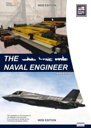
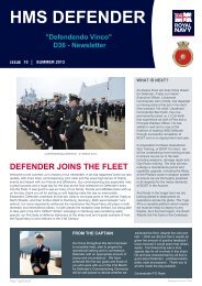
Lieutenant Weller and his seven colleagues parade the Union Flag at the<br />
Olympics Opening Ceremony<br />
me as we started to march into the I was also fortunate to be selected<br />
stadium. The atmosphere generated as I/C of the Naval ceremonial team<br />
by 80,000 people was immense and at the O2 arena for the remaining<br />
the noise levels were indescribable. period of the games, where the<br />
Listening to all of those people team undertook ceremonial duties<br />
cheering for you and knowing in the for 18 finals including Gymnastics,<br />
back of your mind that you were live Trampoline, and Basketball. It was<br />
in front of an estimated TV audience a privilege to represent the country<br />
of four billion people. If I had made and my Service; being able to<br />
a mistake or fallen out of step it participate in this once in a lifetime<br />
would haunt me for the rest of my opportunity is something I will never<br />
career!<br />
forget.”<br />
Ocean’s<br />
Experience<br />
By Cdr J.J. Bailey, Cdr (E)<br />
and Lt Oli Fairbairn, SSEO<br />
Preparing for and deploying on<br />
Joint Operations is something<br />
HMS Ocean and her Ship’s<br />
Company have extensive<br />
experience of; operating from open<br />
sea, transporting an embarked force<br />
into the littoral and flexing her Ship<br />
to Objective Manoeuvre (STOM)<br />
capabilities is what she does.<br />
HMS Ocean deployed from Plymouth<br />
to Greenwich, on the River Thames<br />
on completion of an early summer<br />
leave period, passing the Thames<br />
Barrier inbound on Friday 13 July<br />
2012 (!) without incident or more than<br />
a few metres to spare. On station<br />
the task was to operate helicopters<br />
for both the Air and Maritime security<br />
plans in support of the Metropolitan<br />
Police and provide accommodation<br />
for our TAG and up to circa 500<br />
Venue Security Personnel (mostly<br />
Army) as embarked forces who<br />
made up the Venue Security<br />
Force for the Greenwich Olympic<br />
Equestrian site. The air group, for<br />
the most part at five minutes notice<br />
to launch, reducing to up to 45<br />
minutes on occasions, provided<br />
both Air STOP and Maritime STOP<br />
capabilities to complement the high<br />
speed interception capabilities of<br />
the Eurofighter Typhoon squadron<br />
forward deployed to RAF Northolt.<br />
This meant support systems were<br />
required to be maintained at, or very<br />
near to, immediate notice in support<br />
of aviation throughout the time on<br />
task upriver of the barrier.
3<br />
Preparations for Ocean’s<br />
Op Olympic deployment were<br />
methodical and broad thinking.<br />
Exercising high tempo aviation<br />
operations from Greenwich<br />
for an exercise week in May<br />
2012 provided opportunities for<br />
lessons to be identified, solutions<br />
generation in slow time and areas<br />
that may develop issues during<br />
sustained operations to be probed<br />
and understood. The engineering<br />
challenges of running a system<br />
to its design threshold are well<br />
known and broadly understood.<br />
Often however, in the envelopes<br />
of military tasking these thresholds<br />
are stretched to use assets in new<br />
ways, maximising the efficiency of<br />
the Armed Forces personnel and<br />
equipment. Mooring in the shallow<br />
waters of the River Thames at<br />
Greenwich, with no ability to<br />
produce our own fresh water, a<br />
salt water cooling system and<br />
firemain system that was highly<br />
effective at dredging most of our<br />
mooring for us coupled with the<br />
task of accommodating up to 1100<br />
personnel in total and maintaining<br />
their hotel services with<br />
embarked forces on continuous<br />
watchkeeping cycles was no<br />
textbook amphibious operation –<br />
effectively we delivered exactly<br />
what Ocean was designed to do,<br />
moving a company’s worth of<br />
personnel ashore on a daily basis.<br />
The majority of the embarked force<br />
had also never lived on a ship<br />
before so education was the key to<br />
maintaining safety and to support<br />
their security of the Greenwich<br />
Olympic Venue. This was ably<br />
provided by a forward thinking<br />
and a prepared engineering team<br />
all set up to rectify all manner<br />
of issues possible on a selfcontained,<br />
command and control,<br />
aviation, transport, accommodation<br />
and public engagement platform.<br />
With a Chippy’s party of only 11<br />
(two senior rates, one leading<br />
hand and eight ETMEs) to cover<br />
a full 22,000 tonnes of operational<br />
real estate, the team stepped up<br />
to the challenge. Heads defect<br />
rectification over the 10 week<br />
period in London alone got through<br />
over 300 bobbins (ordered ahead<br />
of deploying to tackle emergent<br />
defects) and 1120 man hours<br />
alongside 210 HPSW strainer<br />
cleans without starting on the DG<br />
plate coolers that acted like sieves<br />
for the silt drawn through our LPSW<br />
cooling system; another 72 manhours<br />
cleaning to maintain the<br />
material condition of ship’s systems.<br />
The most critical deployment<br />
defect, loss of two of three sewage<br />
transfer pumps, leading to a B2<br />
OPDEF on our ability to sustain<br />
heads facilities to over 200 of our<br />
embarked forces personnel, was<br />
dealt with professionally and timely<br />
with the fragility of the remaining<br />
pump unknown growing the risk<br />
against Ocean’s Op Olympic<br />
accommodation tasking. Support<br />
availability for one-off systems and<br />
non-patternised stores with the<br />
strains on personnel supporting<br />
equipment ashore were felt but<br />
the RN organisation held firm and<br />
achieved risk reduction against the<br />
defect to sustain Ocean and all<br />
services for her embarked service<br />
personnel. Ocean operates at the<br />
high end of UK maritime influence<br />
activity (approx 20,000 visitors<br />
onboard in the Op Olympic effort)<br />
and her personnel, modestly “just<br />
doing their job”, remained the key<br />
to success of her activities and<br />
deployment through Op Olympic<br />
and back to Devonport where she<br />
is now deep into preparations for<br />
her third major refit, that were on<br />
going long before Op Olympic<br />
preparations.<br />
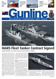
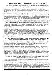
HMS Ocean moored on Greenwich Reach in preparation for Operation Olympic
4<br />
Triumph!<br />
By WO1 ET(ME) Andy Cray MBE,<br />
OCRN SP TP 10 TRG SQN and<br />
CPO ET(ME) Darby Allan,<br />
Group Head ORC Section<br />
10 (LC) Training Squadron, based<br />
in Poole, Dorset is responsible<br />
for conducting, amongst other<br />
things, the Landing Craft vocational<br />
courses for the LC specialisation of<br />
the Royal Marines. As a relatively<br />
small but efficient squadron and<br />
part of 1 Assault Group RM, we<br />
were tasked with providing security<br />
measures for the 2012 Olympic<br />
sailing events at Portland, Dorset.<br />
From the initial planning meetings<br />
it soon became evident that there<br />
would be a requirement for 13<br />
Offshore Raiding Craft (ORC) and<br />
two PAC 24 to be operated and<br />
maintained by 10 Training Squadron<br />
based in RFA Mounts Bay in<br />
Portland Harbour. Our craft would<br />
form part of a larger Task Force<br />
of small craft operated by military<br />
personnel and the Police force,<br />
with the overall command being<br />
the responsibility of HMS Bulwark.<br />
Further recces identified what<br />
equipment would be required to be<br />
deployed and how the craft would<br />
operate from an LSD(A) which<br />
was docked down alongside a jetty<br />
with a floating pontoon tied to the<br />
outboard side of the ship.<br />
With only eight ORC initially<br />
available at Poole, the first act was<br />
to co-ordinate the safe return of<br />
our two craft used for training in the<br />
Falkland Islands back to the UK,<br />
where upon they were serviced<br />
and inspected for hull damage.<br />
(An unfortunate occurrence when<br />
dealing with inexperienced learner<br />
RM boat drivers!) To augment<br />
the flotilla further we “borrowed”<br />
three ORC from our sister units,<br />
539 ASRM and 43 Cdo FPGRM,<br />
based at Turnchapel and Faslane,<br />
along with two PAC 24s for boarding<br />
operations.<br />
With all the pre-deployment preps<br />
completed – craft fully serviced,<br />
equipment such as trailers and<br />
containers transferred by landing<br />
craft to RFA Mounts Bay, extra<br />
personnel trained and additional<br />
equipment, such as blue lights and<br />
positional awareness GPS systems,<br />
fitted – the flotilla was ready to<br />
sail. However nobody had booked<br />
suitable weather and the British<br />
summer struck again; due to the<br />
poor conditions the initial attempt at<br />
sailing around to Portland had to be<br />
aborted until later in the day!<br />
Eventually the flotilla from Poole,<br />
including around 10 RN engineers<br />
(consisting of all ranks from WO1<br />
to ET), arrived in theatre and<br />
embarked in RFA Mounts Bay,<br />
along with hundreds of other<br />
service and civilian personnel<br />
supporting the Olympic sailing<br />
events – accommodation onboard<br />
by this time was at a premium; all<br />
available EMF beds and cabins<br />
were accounted for. After the initial<br />
planned practice and training<br />
evolutions, the daily pattern of<br />
work soon emerged for the small<br />
team of engineering technicians<br />
looking after their steeds. A routine<br />
was soon established which would<br />
ensure that all the boats were<br />
checked over and fuelled by 0700<br />
hours every morning, with any<br />
defects rectified such that the craft<br />
were fit for purpose and ready in<br />
all respects for the day’s tasking<br />
on the waters off Weymouth and<br />
Portland. A full craft status report<br />
was communicated to Bulwark at<br />
the end of every day.<br />
The high tempo operational tasking<br />
required maximum craft availability,<br />
which therefore required any<br />
reported defects which occurred<br />
during the daily patrols to be<br />
The Task Group<br />
immediately rectified, where<br />
possible, after the day’s activities.<br />
Craft coxswains were regularly<br />
interrogated to ensure that any<br />
emergent defects were captured<br />
and dealt with accordingly. This<br />
often kept the team busy well<br />
into the night to ensure that<br />
maintenance routines and defects<br />
were driven down to a minimum,<br />
ensuring the craft were available<br />
for the next day. Some reliability<br />
issues were identified, the biggest<br />
concern being the continued<br />
unreliability of the standard fit<br />
Raymarine GPS units, with several<br />
items requiring replacement. Many<br />
other defects were successfully<br />
rectified by the team; these<br />
included anything from oil leaks,<br />
bilge pump issues and engine circ<br />
water pumps to complete engine<br />
changes.<br />
Unfortunately two ORC required<br />
engine changes, but thankfully<br />
these were due to rare failures<br />
to the tune of a cracked piston in<br />
one and a low lube oil pressure<br />
indication in another. To carry out<br />
this evolution, the craft required<br />
extraction from the water via<br />
the mother ship’s floating dock<br />
at the stern of the vessel to its<br />
maintenance cradle on the vehicle<br />
deck. Initially, this proved to be<br />
challenging and too time consuming<br />
due to the requirement to utilise<br />
two separate lifting gantries<br />
to successfully carry out the<br />
procedure in a safe manner. Given<br />
the extremely tight time frame to<br />
complete the engine change, a<br />
decision was taken to adapt and
5<br />
utilise an existing launching trailer<br />
(held in Poole) which significantly<br />
improved the process to extract the<br />
craft from the dock and transfer it<br />
to the maintenance cradle on the<br />
vehicle deck. A piece of ingenuity<br />
that saved valuable time!<br />
Such was the engineering<br />
prowess displayed by the<br />
engineering team that the CO<br />
of HMS Bulwark commented<br />
on how impressed he was with<br />
the reliability and availability<br />
demonstrated by the ORC during<br />
the Olympic and Paralympics<br />
campaigns – not one single tasking<br />
was missed! (Little did he know<br />
of the technical dramas that were<br />
unfolding behind the scenes; which<br />
is often the case with the ME world<br />
of engineering.) A good analogy<br />
which sums up the operation is<br />
that of a swan – sleek and elegant<br />
on the water but paddling like mad<br />
to keep things moving underneath!<br />
Operation Olympics in Portland<br />
was deemed very successful,<br />
and upon completion of the<br />
tasking all craft were successfully<br />
delivered back to their respective<br />
parent units in one piece, unlike<br />
our stores container onboard<br />
RFA Mounts Bay which was last<br />
seen in Gibraltar! The Offshore<br />
Raiding Craft not only proved their<br />
worth and fit for purpose, but the<br />
Engineering team proved to be<br />
a valuable asset and justifiably<br />
proud of their achievements, whilst<br />
enjoying the once in a lifetime<br />
experience.<br />
Operation Minerva – Training<br />
Management Support to the<br />
Olympics<br />
Lt Cdr K L Mehta, NETS OPS OC<br />
Operation Minerva was initiated by<br />
the Army Education and Training<br />
Service (ETS) branch to deliver<br />
accredited exams to Armed Forces<br />
personnel employed as part of the<br />
security force for the London 2012<br />
Olympics.<br />
As part of Operation Olympics,<br />
7500 armed forces personnel<br />
were deployed to support venue<br />
security for the London 2012<br />
Olympics. After engaging with the<br />
deployed troops, Commander<br />
Land Forces (CLF, General Sir<br />
Nick Parker KCB CBE) decreed<br />
that all personnel who had<br />
completed the G4S Venue Security<br />
Force training should be given<br />
the opportunity to achieve the<br />
same accredited awards as the<br />
G4S security guards. The RN<br />
adopted the same stance within a<br />
day of CLF’s announcement and<br />
as a result the Army ETS branch<br />
initiated ‘Operation Minerva’. The<br />
accreditation given consisted of<br />
three multiple choice papers and<br />
a practical assessment, with the<br />
theory paper exams given to the<br />
personnel ‘in situ’ at Olympic sites<br />
and accommodation areas and<br />
the practical to be conducted by<br />
each service on return to units.<br />
Successful completion would result<br />
in two City & Guilds awards from<br />
the Security Industry Authority;<br />
Security Guarding Level 2 and<br />
Door Supervision Level 2.<br />
To support the ETS and to cover<br />
the Naval contingent deployed<br />
to Op Olympics, a team of TMs,<br />
led by the Naval Education and<br />
Training Service (NETS(OPS)), was<br />
deployed to London, HMS Ocean,<br />
Weymouth and HMS Bulwark. With<br />
two days notice, the RN team went<br />
armed with sleeping bags and kit<br />
to London for a briefing in ETS HQ<br />
in the Royal Artillery Barracks,<br />
Woolwich. What followed was a<br />
full-on fortnight of ground recces,<br />
troop briefings, exam administration<br />
and exam invigilation. Impressively,<br />
after a lot of Ops planning and<br />
leave juggling, seven NETS(Ops)<br />
personnel and two volunteers from<br />
elsewhere in the TM specialisation<br />
were released – an impressive<br />
number at such short notice which<br />
maintained RN visibility throughout<br />
Op Minerva.<br />
Ops Room at Woolwich RA Barracks<br />
Accommodated in a variety of<br />
locations, the RN team was able<br />
to cover most central London<br />
Olympic sites and the main camp<br />
(Chickerell) in Weymouth. After<br />
the initial HQ brief and a City and<br />
Guilds presentation it was clear that<br />
the Operation had been organised<br />
at very short notice and initial recce<br />
and set-up work was still required.<br />
This led to the first couple of days<br />
being spent accessing sites, gaining<br />
security passes, speaking to<br />
Comms Centre military personnel<br />
from all Services and briefing troops<br />
on the accreditation and what we<br />
were trying to achieve. The key was<br />
to do as much work up front and to<br />
get as many contacts in place to aid<br />
the future exam work, and the RN<br />
excelled, swiftly gaining entrance<br />
and setting up initial programmes of<br />
testing that ensured the success of<br />
the later weeks.<br />
With so many troops to test it was<br />
always going to be a challenge. The<br />
exams were not compulsory, but<br />
initial indications showed that most
6<br />
would want to take them. Overall, the<br />
takeup completed in two weeks was<br />
around 3000 personnel – considering<br />
that a large proportion of contingency<br />
personnel left early, this was a good<br />
number of initial assessments.<br />
The main challenge was finding<br />
suitable City and Guilds approved<br />
exam testing venues. In some<br />
instances, exams were conducted<br />
in security search tents or in<br />
temporary dining halls between<br />
meals. The areas covered included<br />
Weymouth, Greenwich Park,<br />
Tobacco Docks, Chatham Docks,<br />
HMS Ocean and Horseguards<br />
Parade. Logistically this made daily<br />
work complex but was eased by<br />
the free travel for<br />
military personnel<br />
across London<br />
during the period.<br />
Overall, Op<br />
Minerva was very<br />
busy but enjoyable<br />
and provided<br />
an excellent<br />
opportunity to<br />
contribute to the<br />
military contingent<br />
for the Olympics.<br />
Additional<br />
testing continued<br />
throughout the Paralympics,<br />
and work is still ongoing for all<br />
three services on the overall<br />
A converted Search Bay area!<br />
accreditation, practical intervention<br />
assessments and the administration<br />
of results, re-sits and awards.<br />
Testing in Horseguards Parade<br />
Testing in Tobacco Docks dining area<br />
PORTLAND<br />
SECURITY<br />
By Lt Billy Ralston<br />
Learning & Development Officer,<br />
DISC<br />
The Venue Security Force (VSF)<br />
at the Olympic Sailing Venue in<br />
Portland, Dorset, consisted of six<br />
Royal Navy officers as Command<br />
and Control and approximately<br />
200 other ranks from 42<br />
Commando Royal Marines, 30<br />
Commando IX Group, the Royal<br />
Marines Band Service and the<br />
Royal Wessex Yeomanry. The<br />
command and control element<br />
was based in ‘Venue Bronze<br />
Command.’ Venue Bronze was<br />
manned 24/7 for the duration of<br />
both the Olympic and Paralympic<br />
Games and enabled empowered<br />
members of the Armed Forces,<br />
Police, Fire, Ambulance, local<br />
Council, G4S and the London<br />
Organising Committee of the<br />
Olympic Games to communicate,<br />
organise effectively and escalate<br />
issues to Silver and Gold<br />
Commands as required. At some<br />
points, especially during the<br />
between-games period, the 12<br />
hour night shift dragged and was<br />
only brightened by watching live,<br />
‘You’ve Been Framed’ moments on<br />
the Weymouth CCTV: highlights<br />
included a stumbling drunk getting<br />
his head stuck between a wall<br />
and a drainpipe and an amorous<br />
couple on the beach.<br />
After the area went into security<br />
lock-down, which involved aboveand<br />
underwater bomb sweeps,<br />
sealing drains and erecting security<br />
fences around the area to control<br />
access and egress, the VSF stood<br />
up. Interestingly, there were also<br />
state of the art Kevlar booms<br />
and sonar systems to prevent<br />
unauthorised boats and warn off<br />
unauthorised swimmers and divers.<br />
The booms and sonar systems<br />
were controlled from Venue<br />
Bronze.<br />
Duties undertaken by VSF members<br />
at the Athletes’ Village and venue<br />
were vehicle searching, personal<br />
searching, X-ray scanning, static<br />
guarding and perimeter patrolling.<br />
The Portland site was significantly<br />
different from the other Olympic<br />
venues in that knives were regularly<br />
allowed through the search area<br />
as competitors and rescuers might<br />
have needed them to untangle<br />
themselves in an emergency<br />
situation. The other main difference<br />
from other areas was that no<br />
spectators came through the venue
7<br />
as the spectator area was three<br />
miles away in Weymouth itself: this<br />
significantly improved throughput of<br />
the search areas as people got to<br />
know what activated the scanners<br />
and what they could retain on their<br />
person.<br />
When not on duty there was<br />
the opportunity to explore the<br />
Chesil Beach area and walks and<br />
runs on the Jurassic Coastal path<br />
were popular, as was sampling the<br />
nightlife in ‘Weybiza.’ Interestingly,<br />
the local taxi drivers spoke of the<br />
trade being down on a normal<br />
summer. In their opinion, visitor<br />
numbers were overestimated,<br />
resulting in hotels cancelling their<br />
normal coach-trip companies<br />
in the promise of better paying<br />
guests who did not appear.<br />
Personnel Search Area<br />
Archery and<br />
boxing Flag<br />
Ceremonial<br />
Team<br />
By WO2 Stirling “Spike” Way<br />
Submarine Admin + Personnel,<br />
NBC Devonport<br />
I am WO2 Stirling “Spike” Way<br />
and was nominated as the team<br />
leader for flag raising duties at the<br />
Olympic archery and boxing victory<br />
ceremonies.<br />
Initial training took place at MWS.<br />
This included a baseline flag-raising<br />
drill along with plenty of other<br />
briefings about security, the media<br />
and what to expect from LOCOG. We<br />
were then all left until the seemingly<br />
chaotic roll-call at Feltham Barracks<br />
a week before the event. We were all<br />
perhaps a little concerned because<br />
there were literally thousands<br />
of troops milling about and all<br />
apparently living in huge field tents<br />
bolted into the parade ground!<br />
Upon arrival at Woolwich Barracks<br />
our fears were allayed, being<br />
accommodated in real buildings,<br />
with real facilities like running<br />
water, showers even! Compared<br />
to the horrors of Tea Wharf where<br />
1500 personnel were ‘living’ in a<br />
warehouse, we were indeed living<br />
the dream! OK it was a Transit<br />
Accom dream but certainly not the<br />
nightmare most others were likely to<br />
be experiencing.<br />
Training for flag-raising was patience<br />
draining but you know there are<br />
worse places to be left waiting<br />
for something to happen than the<br />
England changing room at Lords.<br />
Lunch was a pretty arduous affair<br />
also… You can imagine the trauma<br />
we felt eating it while looking over<br />
the hallowed turf from the executive<br />
lounge. Tough times indeed.<br />
After the training we were quickly<br />
into the detail with Archery starting<br />
straight away. There were plenty of<br />
highlights with respect to the sport,<br />
but for us a lot of the enjoyment<br />
was derived from watching how<br />
the ‘Professional Event Organisers’<br />
rushed around, while we pretty much<br />
chilled out as everyone else seemed<br />
to be losing their heads. Some were<br />
quite taken aback at how relaxed<br />
we were and how quickly we could<br />
switch to “Doing our job” role – for us<br />
it wasn’t exactly rocket science.<br />
At the ExCel centre it was very<br />
different because we were right<br />
in the pugilistic mix. Again the<br />
Organisers rushed around while we<br />
were able to take the opportunity of<br />
interacting with the boxers. Meeting<br />
the British and Irish winners was<br />
certainly a highlight along with<br />
speaking at length with Wladimir<br />
Klitschko, the Super Heavy Weight<br />
Champion of the world. And with a<br />
roof over us the atmosphere was<br />
almost overwhelming; certainly the<br />
proudest moment was being able<br />
to salute the Union Flag raised<br />
for Nicola Adams, the first female<br />
boxing gold medallist in Olympic<br />
history.<br />
For us all the organisation<br />
was good with regard to<br />
accommodation and travel<br />
arrangements. Indeed it was a<br />
joy to be so readily welcomed<br />
wherever we went, certainly<br />
members of London Transport<br />
and the Police were all keen to<br />
acknowledge us in uniform, while<br />
the public frequently just started<br />
speaking with us or wanted a<br />
photograph with them surrounded<br />
by Servicemen.<br />
For us in Team 8, it was brilliant!
8<br />
RIB Coxswain<br />
By POMEM(L) “Morph” Clayton<br />
SFM Defiance Workshop<br />
HMS Drake<br />
Following a request for volunteers<br />
in March of this year, I put my name<br />
forward for RIB Coxn, for the sailing<br />
at Weymouth.<br />
At this point the Olympic Manpower<br />
Command structure seemed<br />
to “have disappeared” and no<br />
information was forthcoming despite<br />
constant requests.<br />
Finally, three months later, on the<br />
Thursday prior to the Double Bank<br />
Holiday I received a phone call to<br />
say my three week training course<br />
would start the following Monday.<br />
Along with the rest of the course,<br />
this was inconvenient timing and<br />
was not popular with families losing<br />
our Double Bank holiday at such<br />
short notice, due to someone else’s<br />
poor planning.<br />
With no choice, I rocked up at<br />
Jupiter Point the following Monday,<br />
as instructed, with about another<br />
25 equally disgruntled potential<br />
coxns. There was a varied mixture<br />
of young and old, junior rates up to<br />
a Lieutenant, with the only thing in<br />
common being the Thursday phone<br />
call. The training staff at Jupiter<br />
Point were equally in the dark about<br />
what to teach us and had only just<br />
received the boats that we were to<br />
use. Fortunately the staff utilized<br />
their experience and put together a<br />
good course. We were all desperate<br />
for information, and finally a<br />
Colonel RM from HMS Bulwark<br />
came to speak to us about what<br />
he believed would be happening.<br />
Although we all left the course as<br />
qualified coxns, we were still pretty<br />
much in the dark about the details<br />
of what we were going to be doing.<br />
The most senior members of our<br />
course, an MAA and the Lieutenant,<br />
took it upon themselves to find out<br />
more information and forward it via<br />
email or phone. Information started<br />
to trickle through as the event got<br />
nearer.<br />
Four weeks later we had our kit<br />
packed, and caught a coach to<br />
Portland. We were accommodated<br />
on RFA Mounts Bay which was<br />
perfectly adequate for this task.<br />
We were issued specialist clothing<br />
items from the Mounts Bay. It was<br />
fortunate that we had three Seaman<br />
Specs as part of the group, as they<br />
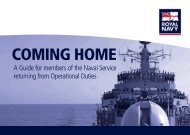
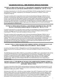
Weymouth<br />
1.6nm<br />
1.6nm<br />
0.6nm<br />
1.6nm<br />
1nm<br />
Precautionary Area<br />
Sailing<br />
Venue<br />
Portland<br />
Precautionary Area<br />
Weymouth & Portland<br />
Approach Area<br />
Mooring/Anchorage<br />
Sailing Courses<br />
Competition Areas<br />
Commercial Anchorage<br />
Approach Sector<br />
Weymouth and Portland Sailing Areas
9<br />
were able to ensure our safety<br />
equipment was in good order as it<br />
had been “storob’d” from around the<br />
fleet and some items were blatantly<br />
“second hand”. We spent the next<br />
few days having lots of briefs and<br />
getting to know the police crews<br />
that we would be teamed up with.<br />
Prior to the Olympic sailing events<br />
starting for real, we spent two<br />
days in our shift patterns, doing<br />
exercises, and learning the local<br />
areas. There was a layered<br />
defence system in place to protect<br />
the sailing areas from being<br />
encroached, whether accidentally<br />
or deliberately. The first layer being<br />
local fishing boats directing vessels<br />
via radio. The RN contingent<br />
was the second layer in unarmed<br />
RIBs, accompanied by two Police<br />
Officers. There were also a number<br />
of armed police RIBs, and the RM<br />
ORCs. This was all backed up by<br />
a Merlin helicopter and we were<br />
under the control of HMS Bulwark.<br />
The exercises consisted of various<br />
scenarios from “blatantly clueless”<br />
boats encroaching on the sailing<br />
areas to “rogue terrorist vessels”<br />
attempting to break the cordon.<br />
The early shift started at Portland<br />
Marina at 0700 for briefing. Each<br />
crew were allocated a different boat<br />
each day, and this was the time to<br />
find out our area, and to obtain an<br />
up to date weather report. The Coxn<br />
would then draw the keys for the<br />
boat and sign out a Police radio.<br />
The other crew also received their<br />
individual briefs, and then we would<br />
proceed to our allocated vessel. We<br />
would check the boat over, make<br />
ourselves comfortable and then<br />
proceed to our allocated area. We<br />
were to be on station by 0800 to<br />
allow two hours to secure the cordon<br />
before allowing the Olympic sailing<br />
boats and their support vessels<br />
uninterrupted access from 1000.<br />
We would eagerly anticipate the<br />
arrival of the “Shuttle” boat which<br />
would bring our bag meals out to<br />
us. This was the highlight of any<br />
shift. We would patrol our allocated<br />
area, listening out on the radio<br />
for any possible instructions from<br />
Bulwark. Depending on the day’s<br />
area, we could be out there until<br />
between 1400–1700 before relief.<br />
The afternoon shift would start<br />
with the brief at 1300, and then a<br />
succession of shuttle boats to carry<br />
out handovers. There was one<br />
shuttle for four boats, and we could<br />
carry two crews in the boat. Due<br />
to strict speed limits in the harbour<br />
and around the cordon, it would<br />
take over half an hour to reach the<br />
furthest point with the first two crews,<br />
and if you were last it could be 1700<br />
before you were back alongside. The<br />
procedure did improve towards the<br />
end to reduce this time. The racing<br />
would typically finish between 1700<br />
and 1800, and once all Olympic<br />
vessels were safely back in harbour<br />
we would “stand down”.<br />
Most of the days were uneventful,<br />
however my vessel was twice<br />
tasked with a “Blue Light”<br />
response. The first time was to<br />
head off a yacht that had not<br />
responded to instructions. The<br />
Skipper was a little upset that the<br />
cordon was in place and thought<br />
he “knew best”, acting like a<br />
petulant child. The police officer<br />
on board pointed out the error of<br />
his ways and that was the end of<br />
the incident. The second one was<br />
much more exciting, with a rogue<br />
RIB approaching the cordon at 40<br />
knots, ignoring all radio requests<br />
to slow down and identify himself.<br />
Three RIBs were dispatched to<br />
intercept as well as the Merlin. As<br />
soon as the Rogue RIB realised all<br />
the Blue Lights were heading his<br />
way he immediately slowed and<br />
was compliant, apologising for his<br />
lack of awareness regarding the<br />
cordon.<br />
Overall it was a good experience,<br />
and a chance to do something<br />
different. It was a shame that those<br />
that volunteered had to fight for<br />
every scrap of information leading<br />
up to the event, and that we lost our<br />
Double Bank holiday at such short<br />
notice. The armed forces may have<br />
gained good PR overall from the<br />
Olympics, but the families of those<br />
involved in the Sailing security<br />
at Portland are not so impressed<br />
with the Navy’s organization or<br />
communication.<br />
Senior Military<br />
Rep<br />
By Cdr Mike Toft<br />
DES Ships<br />
The Task<br />
Contrary to the impression that<br />
might have been gained from the<br />
media, a lot of Service personnel<br />
were earmarked for Olympics<br />
duties long before the G4S shortfall<br />
occurred. I was fortunate enough<br />
to be one of those people, swayed<br />
by the opportunity of a “home draft”<br />
for the first time in 16 years and the<br />
rather grand title of Venue Senior<br />
Military Representative, Weymouth<br />
and Portland. Responsible to the<br />
London Organising Committee of<br />
the Olympic and Paralympic Games<br />
(LOCOG) Venue Security Manager,<br />
this role put me in the privileged<br />
position of Commanding Officer<br />
of the 200 military personnel who<br />
would form the Venue Security<br />
Force (VSF) for the Olympic and<br />
Paralympic Sailing Venue. Our<br />
mission – to deliver a safe and<br />
secure games, whilst enhancing the<br />
reputation of the Armed Forces.<br />
A great deal of preparatory work<br />
had already been done by the staffs<br />
of the Joint Military Commander<br />
(Dorset), the Army Brigadier I would<br />
be working for, and the Naval<br />
Regional Commander Wales and<br />
Western England. However there<br />
was still plenty to be done and<br />
from April I was quickly immersed<br />
in numerous training and planning<br />
exercises, supplemented with a<br />
plethora of staff work. The scope<br />
of the task was immense, drawing<br />
me into such things as VSF<br />
training plans, force generation,<br />
accommodation, logistics,<br />
transport, feeding, uniform, legal<br />
powers, policing and discipline. All<br />
fascinating topics, and supported by<br />
more Warning Orders, Op Orders<br />
and Fragmentary Orders than I’ve
10<br />
ever seen. Just three months after<br />
I started work, we were ready to<br />
deploy.<br />
The Venue<br />
Meanwhile LOCOG was working<br />
hard to transform the Weymouth<br />
and Portland National Sailing<br />
Academy into a secure Sailing<br />
Venue and Olympic Village. The<br />
Venue and the Village were two<br />
separate locations, with the Venue<br />
secured by the MOD VSF and<br />
the Village secured by G4S. The<br />
race sites around Weymouth Bay<br />
were secured by the Maritime<br />
Force Commander Dorset, the<br />
CO of HMS Bulwark. LOCOG<br />
requested a small MOD VSF<br />
contingent to start work earlier than<br />
originally planned, so schedules<br />
were quickly re-arranged and we<br />
moved into our accommodation at<br />
Chickerell Territorial Army camp on<br />
30 June, ready for duty on 1 July.<br />
Unfortunately extreme weather and<br />
technical problems meant that the<br />
Venue wasn’t ready to commence<br />
security operations; however<br />
this gave us time to familiarise<br />
ourselves with the area and<br />
The White Ensign flies alongside the Union Flag over Chickerell Camp<br />
proved invaluable for our next big<br />
challenge – supporting G4S.<br />
The Challenge<br />
Initially G4S was able to provide<br />
sufficient personnel at Weymouth<br />
and Portland; however backlog in<br />
the accreditation process meant that<br />
they hadn’t been vetted properly<br />
and in very short order some 40%<br />
of their staff had to be withdrawn.<br />
With the athletes due to arrive at<br />
the Olympic Village on 16 July, the<br />
decision was made to move the<br />
MOD VSF into the Village to provide<br />
support. As well as overcoming the<br />
G4S shortfall, this had the additional<br />
Portland<br />
Marina<br />
Olympic<br />
Village<br />
The Olympic Venue and Village
11<br />
benefit of presenting a much more<br />
robust security appearance to the<br />
public. Many of the Olympic teams<br />
gave positive feedback on how glad<br />
they were to see such professional<br />
and efficient security provided by<br />
the military after all the scare stories<br />
in the press. Watch routines had to<br />
be swiftly amended and additional<br />
manpower provided at short notice<br />
from the Contingency Force. The<br />
MOD VSF covered the gap for a<br />
further 12 days, until G4S was able<br />
to resolve its difficulties and resume<br />
full duties in the Village.<br />
The Highlights<br />
The Ceremonial Team<br />
up such a fine body of men and<br />
women. Throughout the trials and<br />
tribulations everyone performed<br />
to the highest standard both on<br />
and off duty, proving once again<br />
how resilient and professional our<br />
people truly are – the single most<br />
important factor.<br />
Once into our routines, there<br />
was some opportunity to take<br />
in the enormity of what we were<br />
supporting, from visits by Royalty<br />
and other VVIPs through to the<br />
sailing and medal ceremonies.<br />
It was certainly a once in a<br />
lifetime experience, but most of<br />
all I was proud to be heading<br />
Ben Ainslie Gold Medal Ceremony<br />
Bravo Zulus<br />
Congratulations to the RN Engineers who were<br />
awarded commendations for outstanding contributions to<br />
Operation Olympics:<br />
Standing Joint Commander’s Commendations<br />
Lieutenant N. Muyambo<br />
Lieutenant Commander A.J. Thomas<br />
Commander M.D. Toft<br />
Lieutenant Commander R.P. Wallace<br />
Commander N.S. Wright<br />
Maritime Component Commander’s Commendations<br />
The Olympic Flame<br />
Lieutenant M.A. Wakefield<br />
Warrant Officer 1 ET(ME) G. Moss
12<br />
Cutting Edge Integration<br />
Facility Opens<br />
First Sea Lord Opens<br />
QE Class Mission System Integration Facility<br />
By the Editor<br />
Lieutenant Commander Alastair Graham, DE&S<br />
Maritime Combat Systems, QEC Acceptance<br />
officer, demonstrating the key capabilities offered<br />
by the Lyster Building integration facility to the<br />
First Sea Lord<br />
Admiral Sir Mark Stanhope, the First<br />
Sea Lord, opened Lyster Building,<br />
the Queen Elizabeth Class Mission<br />
System Large Scale Integration<br />
Facility, at HMS Collingwood on<br />
12 September 2012. The facility,<br />
established at a cost of £1m, will<br />
allow full-scale testing of the ships’<br />
mission system, using the actual<br />
hardware which will subsequently<br />
be fitted in HMS Queen Elizabeth,<br />
thus de-risking the installation at<br />
an early stage, and increasing<br />
confidence that the Mission<br />
System (MS) will be fit for use in<br />
the planned timescale. Investing in<br />
shore integration facilities reduces<br />
the time required to conduct costly<br />
mission system acceptance trials on<br />
the ships from years to months.<br />
The Mission System is the “brain” of<br />
the ship, which enables it to conduct<br />
air traffic control, navigation, tactical<br />
picture compilation, communications,<br />
mission planning for the embarked<br />
F-35 Joint Strike Fighters and<br />
Merlin helicopters and to carry<br />
out engineering maintenance and<br />
logistics support. Whilst the MS’s<br />
Illustrations courtesy of Photography<br />
Department, HMS Collingwood<br />
complexity is<br />
a step change<br />
from existing<br />
systems,<br />
much of its<br />
capabilities are<br />
described as<br />
evolution, rather<br />
than revolution;<br />
operators<br />
familiar with<br />
Type 23 or<br />
Type 45, or with<br />
aircraft control<br />
at airfields<br />
ashore, will find<br />
that many of<br />
the “building<br />
blocks” of the<br />
new MS are<br />
not unfamiliar – but the scale of the<br />
system is significantly greater than<br />
any predecessor. The MS will bring<br />
together the combat management,<br />
communications and visual<br />
surveillance systems on the ship’s<br />
fibre-optic network and integrate<br />
these key capabilities on a scale<br />
never undertaken in previous ships<br />
– the QEC MS has twice as many<br />
interfaces as Type 45’s CMS.<br />
The equipment in Lyster Building<br />
will allow engineers to test the MS<br />
in all its roles and functions – they’ll<br />
be assisted by trainees from the<br />
Maritime Warfare School, both<br />
as operators, who will stress the<br />
system by putting high-intensity<br />
loading on the various elements,<br />
and as maintainers to look at<br />
the impact on maintenance<br />
requirements. Once the tests<br />
are complete, and the relevant<br />
compartments in HMS Queen<br />
Elizabeth are ready to receive<br />
the kit (currently planned for the<br />
second and third quarters of 2013),<br />
the hardware and software will be<br />
packaged up and sent to Rosyth<br />
for fitting. The hardware will be slid<br />
into its racking on board, powered<br />
up, and a similar series of tests run<br />
on board to prove the MS in situ,<br />
using the same control system for<br />
emulation as in Lyster Building<br />
(which, incidentally, uses the same<br />
system as is used in MWS’ MCTS 1 ).<br />
Just a few facts about the system:<br />
• Those familiar with older ships<br />
will not find a computer room –<br />
instead there are a large number<br />
of node rooms which provide<br />
considerable redundancy on a<br />
network that is designed to heal<br />
itself following action damage.<br />
• 300 cameras are provided<br />
for surveillance of unmanned<br />
spaces and visibility of “outof-sight”<br />
areas (eg under the<br />
flare of the bow, or flight-deck<br />
overhangs) and all of these<br />
are linked to the MS – and all<br />
of them are part of the testing<br />
taking place in Lyster Building<br />
(the ones to be fitted on<br />
weather decks are known as<br />
“Metal Mickeys” – a nickname<br />
which will only mean something<br />
to those familiar with certain<br />
1980s TV shows).<br />
1. See the Winter 2011 edition of TNE.<br />
A “Metal Mickey” – one of the<br />
weather deck surveillance cameras
13<br />
The First Sea Lord formally opening Lyster Building.<br />
Left to right: Steve Dowdell, BAE Mission System Director,<br />
Rear Admiral Steve Brunton, Director Ship Acquisition<br />
DE&S, 1SL and Commodore Mike Mansergh CBE,<br />
Commodore Maritime Warfare School<br />
• Four integration facilities for<br />
various elements of the QEC’s<br />
systems are now up and<br />
running, at Portsdown, Crawley,<br />
Cowes on the Isle of Wight and<br />
Collingwood.<br />
• Some elements have already<br />
been proven – for example,<br />
HMS Prince of Wales’s Link 16<br />
has already linked from<br />
BAE Cowes to the Type 45<br />
reference set at Portsdown,<br />
and has just successfully<br />
completed collaborative<br />
over-the-air testing with<br />
HMS Illustrious.<br />
In opening Lyster Building, Admiral<br />
Stanhope paid tribute to its<br />
namesake: “Lyster was a leader<br />
and innovator in delivering Air<br />
Power from the Sea; and this will<br />
be the primary role for the Queen<br />
Elizabeth class carriers, as part<br />
of our Future Navy 2020 vision.<br />
It is apt therefore that the Aircraft<br />
Carrier Alliance should take him<br />
as their inspiration in developing<br />
this world-class engineering and<br />
training facility that will help ensure<br />
HMS Queen Elizabeth enters front<br />
line service before the end of the<br />
decade.”<br />
Want to Know More?<br />
For further information please contact:<br />
Commander Steve Roberts<br />
Maritime Combat Systems – QE CSM<br />
Tel 0306 793 5459 or 9679 35459<br />
DII: DES SHIPS MCS-SSCSG-QE-CSM<br />
Why “Lyster Building”?<br />
Vice Admiral Sir Lumley Lyster,<br />
KCB, CVO, CBE, DSO, captained<br />
the aircraft carrier HMS Glorious<br />
in the late 1930s, during which<br />
time he developed plans to<br />
attack the Italian Fleet using<br />
carrier-based air power, in the<br />
event of hostilities, in its base of<br />
Taranto. Subsequently, as Rear-<br />
Admiral Aircraft Carriers in the<br />
Mediterranean Fleet in 1940,<br />
flying his flag in HMS Illustrious,<br />
he commanded Operation Judgement, the attack on<br />
Taranto by Swordfish torpedo-bombers; based on his<br />
earlier planning, this attack knocked out half of the<br />
Italian Fleet’s battleships and materially altered the<br />
balance of maritime power in the Mediterranean.<br />
After declaring the building open,<br />
he presented Rear Admiral Steve<br />
Brunton, Director Ship Acquisition<br />
DE&S, with a “Queen Elizabeth” cap<br />
tally which Admiral Brunton would,<br />
in turn, present to the first member<br />
of her Ship’s Company, who would<br />
join her in October 2012 – the first<br />
of her RN engineers was to join<br />
in March 2013. (The cap tally was<br />
subsequently presented to Leading<br />
Writer Claire Butler on 2 October<br />
2012 in a ceremony at Rosyth.)<br />
Glossary of Terms<br />
CMS Combat Management System<br />
MCTS Maritime Composite Training<br />
System<br />
MS Mission System<br />
MWS Maritime Warfare School<br />
QEC Queen Elizabeth class<br />
C-DOCS – Submarine Combat System Documentation<br />
Dear Editor,<br />
Just a brief comment about “Editor’s<br />
Corner” in a recent issue of TNE:<br />
In the TNE Summer Issue,<br />
you mention the distribution of<br />
The Naval Engineer in its various<br />
guises. An additional method<br />
of distribution, which was not<br />
mentioned in your article, is the<br />
inclusion of the three most recent<br />
issues of TNE within C-DOCS.<br />
Aimed primarily at the submarine<br />
fraternity, C-DOCS provides<br />
technical information about the<br />
Combat System and is distributed<br />
to all submarines by Restricted<br />
CD-ROM media, as well as being<br />
available on the RLI 1 .<br />
Regards,<br />
Steve Osliff MBCS, MInstLM<br />
Combat System Senior Engineer<br />
SSMG Combat Systems<br />
Babcock Integrated Technology<br />
Devonport House<br />
PO Box 77<br />
Keynsham BS31 2YH<br />
1. http://www.dgsm.dii.r.mil.uk/cdocs/cdocs.htm
14<br />
Innovative all-electric<br />
launch solution for<br />
future electric submarine<br />
By Daniel Pettitt MEng MIET<br />
R&D Manager – Defence Systems Technology,<br />
Marine & Technology Division, Babcock International Group<br />
Editor’s View<br />
Developments in the use of electric<br />
technologies for naval applications<br />
present an opportunity to explore<br />
all-electric payload launch solutions<br />
for a submarine of the future,<br />
with potential benefits including<br />
improved operational capability,<br />
and low through-life cost.<br />
A critical and substantial element of<br />
a submarine’s operational capability<br />
is the ability to launch a payload,<br />
from weapons to countermeasures<br />
and, in the future, potentially,<br />
unmanned underwater vehicles.<br />
The launch system is therefore<br />
a fundamental component, with<br />
specific design requirements. In<br />
Daniel Pettitt holds a Masters of Engineering degree in Electrical<br />
and Electronic Engineering from the University of Nottingham. He<br />
joined Babcock in 2009 and has undertaken a number of projects<br />
focused on the development of electric actuation for submarine<br />
systems and equipment. He now manages the Research and<br />
Development department within Defence Systems Technology,<br />
with the responsibility to deliver a range of development projects<br />
for both submarine and surface ship applications.<br />
addition to providing sufficient exit<br />
velocity to enable the payload<br />
to clear the host submarine and<br />
go on to perform its mission, the<br />
launch must also be performed in a<br />
functionally safe manner (particularly<br />
if crossing the submarine’s pressure<br />
boundary, as with torpedo launch),<br />
and the system must be available<br />
when required, and must not<br />
compromise the submarine’s stealth.<br />
Typically, weapons and other<br />
payloads are launched from a<br />
horizontal tube that provides an<br />
interface between the internal<br />
stowage compartment and the<br />
external environment, in various<br />
Figure 1: HMS Astute’s state-of-the-art weapons handling and launch system<br />
is supplied by Babcock. Future payload launch systems may become ‘allelectric’<br />
in line with moves towards electric systems on naval platforms<br />
UK MOD/Crown copyright 2012<br />
This article discusses the outcome<br />
of company-funded R&D work;<br />
there is currently no MODsponsored<br />
capability development<br />
activity to which it relates, and<br />
the subject is included in TNE in<br />
order to inform you, the reader, of<br />
possible future developments. As<br />
always, the Editor would welcome<br />
your comments.<br />
arrangements for different payloads<br />
and tending to use compressed air<br />
to provide the launch power.<br />
A submarine’s weapons handling<br />
and launch system (WHLS) is one<br />
such example, with Babcock’s<br />
WHLS design, for instance, using<br />
an air turbine pump (ATP) to provide<br />
the motive power to the weapon,<br />
controlled by a programmable<br />
firing valve (PFV) to make the<br />
most efficient use of the firing air,<br />
according to the weapon to be<br />
launched, and providing a covert<br />
means of launching a weapon in a<br />
compact volume. Other payloads,<br />
such as countermeasures, are<br />
typically launched from a single-shot<br />
launcher mounted under the casing,<br />
or through a submerged signal<br />
ejector.<br />
Future launch systems may be<br />
different, potentially becoming<br />
‘all-electric’, in line with moves<br />
towards electric systems on naval<br />
platforms. With an increasing<br />
focus on the benefits to be<br />
gained by electrification of power,<br />
propulsion and auxiliary systems<br />
(including reduced through-life<br />
cost and potential for increased<br />
operational capability), plus ongoing<br />
developments such as<br />
electric weapons and aircraft
15<br />
Figure 2: The submarine of the future may be predominantly, or entirely,<br />
electrically actuated. This may present some challenges for the payload<br />
launch system, but also some valuable opportunities<br />
launch on surface ships, it may<br />
be that the submarine of the<br />
future is predominantly, or entirely,<br />
electrically actuated. For the<br />
payload launch system this may<br />
present some challenges, but also<br />
some valuable opportunities.<br />
New technology options<br />
The possibility of a future electric<br />
submarine presents an opportunity<br />
to use developing technology; in<br />
particular, the electric linear motor<br />
and the ‘rodless cylinder’. The linear<br />
motor, working on a similar principle<br />
to the typical rotary electric motor,<br />
has a stator and rotor (commonly<br />
referred to as a reaction plate) in<br />
a linear rather than a rotary form.<br />
The two main variants – the Linear<br />
Induction Motor (LIM) and Linear<br />
Synchronous Motor (LSM) – have<br />
various differences, but the major<br />
distinction lies in the LSM being<br />
smaller and lighter but requiring<br />
use of permanent magnets in<br />
the reaction plate, whereas the<br />
LIM uses a conductive plate. LIM<br />
technology has been widely used in<br />
the commercial sector and also in<br />
designs for naval applications such<br />
as the EMALS (General Atomics)<br />
and EMCAT (GE Power Conversion)<br />
aircraft launch systems for aircraft<br />
carriers, and the EMKIT Unmanned<br />
Air Vehicle launcher demonstrator<br />
(GE Power Conversion).<br />
The cable-type ‘rodless cylinder’,<br />
operating using compressed air<br />
(as demonstrated on the Babcock<br />
single-shot countermeasure<br />
launcher), is also of interest, being<br />
adaptable to make it suitable for<br />
launching larger payloads, and<br />
with the potential to use a ‘slit’<br />
mechanism suitable for repeatable<br />
launch operations.<br />
Combining LIM and rodless<br />
cylinder technology can overcome<br />
the traditional size disadvantage<br />
of linear actuation methods for<br />
launch systems. By integrating the<br />
LIM stator into the launch tube,<br />
the force-producing equipment is<br />
contained within the tube itself,<br />
providing a launch system with a<br />
very compact volume, that can be<br />
referred to as the Integrated Electric<br />
Launch Tube (IELT).<br />
The IELT arrangement provides<br />
various benefits. The pressure<br />
hull penetrations for the forcegenerating<br />
equipment (being<br />
power and control cables only)<br />
are reduced compared to existing<br />
methods. Additionally, the<br />
launch tube is the same for both<br />
payload launch methodologies<br />
and the speed and acceleration<br />
of the launch operation can be<br />
electronically controlled (similar<br />
to the capabilities of the ATP and<br />
PFV combination) providing an<br />
adaptable solution that can launch a<br />
number of payloads.<br />
Harmonising payload and<br />
launcher<br />
Importantly, the payload and<br />
launcher must be considered as subsystems<br />
of a ‘payload launch system’<br />
in order to achieve a solution that<br />
recognises the practical constraints<br />
of each. This leads to two variants of<br />
the solution. In the first, the reaction<br />
plate is integrated with the payload.<br />
This is the most elegant variation<br />
from a launcher perspective,<br />
reducing the number of components<br />
and simplifying the launch solution,<br />
but has some disadvantages for<br />
the payload, making it complex to<br />
achieve as a system. Firstly the<br />
reaction plate (a conductive sheet)<br />
must be integrated with the payload<br />
in a physically suitable manner<br />
to allow the payload to meet its<br />
operational requirements, and the<br />
launch force required could be large,<br />
which could increase the payload<br />
mass, limit its manoeuvrability, or<br />
reduce the capacity available within<br />
the payload body. Further, heating<br />
of the reaction plate during launch<br />
must be managed. Multiple payload<br />
types would require a defined<br />
interface standard for incorporation<br />
of the reaction plates which could<br />
affect payload capability, and the<br />
electromagnetic field emitted by<br />
the LIM also needs to be closely<br />
managed, particularly with respect<br />
to electromagnetically sensitive<br />
munitions and weapon control<br />
systems, which may make it<br />
unfeasible for some payloads.<br />
The second variant sees the<br />
reaction plate integrated into a<br />
separate ‘reaction unit’. With this<br />
approach the design of the payload<br />
is not compromised, although it<br />
will still need to accept a launch<br />
force applied at the rear. Equally,<br />
the separate reaction unit means<br />
the electromagnetic field is more<br />
local to the reaction unit, and the<br />
effect on sensitive equipment is<br />
minimised.<br />
The reaction unit itself could be<br />
either disposable or re-usable. A<br />
disposable unit would simplify the<br />
control and power system solution,<br />
having no requirement for energy<br />
dissipation or recovery, and loading<br />
of payloads into the tube would<br />
be easier. By avoiding the need to<br />
handle the stresses of continuous<br />
heating and cooling cycles, the<br />
size and cost of the reaction unit<br />
could also be minimised. On the<br />
other hand, a re-usable unit would
16<br />
mean no requirement for stowage<br />
and handling of multiple reaction<br />
units, but the mechanism to install<br />
a weapon past the reaction unit<br />
would need close consideration,<br />
and the unit is likely to be larger<br />
than a disposable option, to combat<br />
the effects of multiple operations.<br />
The control and power system<br />
would also need to be capable of<br />
braking and recovering the reaction<br />
unit from within the tube, which<br />
would increase launcher length to<br />
accommodate a braking zone.<br />
A key benefit is that the IELT design<br />
is the same for both variants, the<br />
only major difference being the<br />
position of the reaction plate with<br />
respect to the payload. A single tube<br />
can therefore be used to launch<br />
payloads with an integrated reaction<br />
plate or a separate reaction unit,<br />
providing an adaptable system.<br />
Design considerations<br />
Among the technical challenges<br />
involved in realising the integrated<br />
electric launch tube configuration is<br />
the need to achieve sufficient force<br />
to launch a weapon within a compact<br />
system volume. However, as the<br />
launch force is applied directly to the<br />
payload, the system is more efficient<br />
than current methods, reducing the<br />
power needed to achieve equal<br />
performance. Given that a launch<br />
operation is discontinuous, analysis<br />
of the duty cycle would allow the<br />
system to be optimised to use the<br />
peak rating of the motor. It is also<br />
anticipated that cooling would not be<br />
required, due to the thermal mass<br />
of a typical launch tube, and the fact<br />
Reaction Plate<br />
Stator<br />
Payload<br />
Tube Structure<br />
that the tube is flooded internally and<br />
externally provides a good thermal<br />
heat sink, although a demanding<br />
salvo launch requirement could<br />
affect this.<br />
The LIM stator, which is typically<br />
formed from a multi-phase<br />
winding in a laminated iron core,<br />
is another factor. It must be<br />
integrated within the launch tube<br />
without compromising its structural<br />
integrity, while also maintaining<br />
corrosion resistance in a seawater<br />
environment. This can be<br />
addressed by encasing the stator in<br />
a non-magnetic material to provide<br />
corrosion resistance.<br />
A further consideration is the<br />
‘airgap’ between the stator and<br />
reaction unit, which needs to be<br />
flooded for the integrated launch<br />
tube. However, the concept is<br />
already in use with canned rotary<br />
induction motors that operate<br />
while flooded, so is not considered<br />
a major design issue. The<br />
acceleration of the payload within<br />
the flooded tube during launch, and<br />
the consequent movement of water<br />
as a result, may, however, have an<br />
effect on the airgap specification.<br />
The tube must also be capable of<br />
providing follow-up water behind the<br />
payload as it is launched.<br />
With regard to the power system<br />
design and control, multiple LIMs<br />
connected via power switches to the<br />
launch inverters provides the most<br />
cost-effective and efficient method<br />
of transferring power to the reaction<br />
unit, and has been proven to operate<br />
successfully in various applications,<br />
Reaction Plate<br />
Stator<br />
notably GE Power Conversion’s<br />
EMKIT UAV launch demonstrator.<br />
This methodology enables the speed<br />
and acceleration of the payload to be<br />
controlled during a launch operation,<br />
allowing different payloads to be<br />
launched from the same tube.<br />
Also relating to power, the pulsed<br />
demand (payload launch being a high<br />
power, discontinuous operation) is<br />
likely to be too high to derive directly<br />
from the submarine electrical supply<br />
and therefore requires a local energy<br />
storage system. Developments in<br />
the surface ship sector to provide<br />
energy storage for UAV launch, as<br />
well as developments for aircraft,<br />
rail gun and directed energy weapon<br />
applications, are of interest here. A<br />
number of technologies exist, such as<br />
ultracapacitors and advanced battery<br />
technology, with the potential to<br />
provide a submarine energy storage<br />
system, after necessary development<br />
and proving for the operating<br />
environment.<br />
Mission modularity<br />
The IELT concept is scalable<br />
in terms of both the launcher<br />
mechanism and the energy<br />
storage, enabling it to be used to<br />
launch a variety of payloads, from<br />
countermeasures using a smaller<br />
scale system to weapons using a<br />
larger scale one, as well as being<br />
applicable to UUV launch and<br />
recovery. This aligns well with a<br />
mission modular approach, as<br />
additional tube modules and energy<br />
storage could be added to adjust<br />
the capability of the launcher to the<br />
platform’s operational requirements.<br />
Tube Structure<br />
Payload<br />
Reaction Unit<br />
REACTION<br />
PLATE<br />
INTEGRATED<br />
WITH<br />
PAYLOAD<br />
REACTION<br />
PLATE IN<br />
EXTERNAL<br />
PUSHER<br />
UNIT<br />
Figure 3: Diagrams showing the LIM integrated with a launch tube and payload, the Integrated Electric Launch<br />
Tube concept. The reaction plate may be integrated with the payload (left) or in a separate ‘reaction unit’ (right)
17<br />
Importantly, the development from<br />
the current state-of-the-art ATP<br />
with PFV launch system to an<br />
electric system to meet the interface<br />
requirements of a future all-electric<br />
submarine can be achieved in<br />
a series of incremental steps by<br />
electrifying individual sub-systems.<br />
This will ensure minimised risk,<br />
while ultimately providing an allelectric<br />
system with a compact<br />
volume, and contributing to a<br />
low through-life cost at platform<br />
level. Moreover, there is further<br />
potential for the IELT concept to<br />
be developed into a true external<br />
tube that aligns with the mission<br />
modular submarine concept,<br />
enabling the submarine to adapt<br />
its payload launch capability<br />
according to mission requirements.<br />
In short, the development of an<br />
all-electric payload launch system<br />
for submarines is not without its<br />
challenges, but also presents<br />
valuable opportunities.<br />
Want to Know More?<br />
For further information please<br />
contact:<br />
Daniel Pettitt, R&D Manager,<br />
Babcock International Group<br />
Ashton House, Ashton Vale<br />
Road, Bristol BS3 2HQ<br />
+44 (0)1173 449 312 daniel.<br />
pettitt@babcockinternational.com<br />
Glossary of Terms<br />
ATP Air Turbine Pump<br />
EMALS Electromagnetic Aircraft<br />
Launch System<br />
EMCAT Electromagnetic Catapult<br />
EMKIT Electromagnetic Kinetic<br />
Integrated Technology<br />
IELT Integrated Electric Launch<br />
Tube<br />
LIM Linear Induction Motor<br />
LSM Linear Synchronous Motor<br />
PFV Programmable Firing<br />
Valve<br />
UAV Unmanned Aerial Vehicles<br />
UUV Unmanned Underwater<br />
Vehicle<br />
WHLS Weapons Handling and<br />
Launch System<br />
Recollections<br />
of World War II<br />
The Eastney<br />
Microwave “Oven”<br />
The advent of the 1 megawatt peak<br />
power 10 cm magnetron heralded<br />
almost a quantum leap forward in<br />
radar development. Harnessing<br />
the actual radio frequency power<br />
and transferring it to the aerial was<br />
in itself quite difficult, and many<br />
designs were tried and tested<br />
before a satisfactory solution<br />
was found. A Polish major was<br />
instrumental in designing a suitable<br />
launching device which projected<br />
the radio frequency power into a<br />
3 inch x 1 inch rectangular brass<br />
tube known as a wave guide.<br />
The design and dimensions of<br />
the wave guides resulted from<br />
advanced mathematics, much of<br />
which stemmed from the pens of<br />
some Polish mathematicians who<br />
had escaped from Poland and<br />
had joined the Admiralty scientific<br />
teams.<br />
George King was given the task<br />
of co-ordinating all the other<br />
components of a new high power<br />
centrimetric radar which was to be<br />
the nucleus of a new generation of<br />
land based and sea borne sets.<br />
Taken from Journal of Naval<br />
Science Vol 16 No 4.<br />
Whilst all the separate<br />
components such as pulse<br />
transformers, modulators, aerials,<br />
wave guide rotating joints, receiver<br />
protection water vapour switches<br />
and the TRE 1 developed Plan<br />
Position Indicator (PPI) were going<br />
through their natural progressions,<br />
George King hand-made a wave<br />
guide and horn to transmit the<br />
power of the new high power<br />
monster into the laboratory – just<br />
above our heads.<br />
The embryo transmitter and<br />
modulator were sited in a 15 ft x<br />
15 ft wooden hut on the flat roof<br />
of one of the laboratories at EFE 2 ,<br />
the access to which was by a 20 ft<br />
vertical steel ladder – rather like<br />
climbing up a ship’s side.<br />
One of the first tasks was to assess<br />
the life expectancy of the new<br />
magnetrons now being produced<br />
by the GEC 3 factory and to this end<br />
we started a life test, taking it in<br />
1. Telecommunications Research<br />
Establishment.<br />
2. Eastney Fort (East) – used during the<br />
war by the Admiralty Signals Establishment<br />
for development of naval radar.<br />
3. General Electric Company.<br />
turns on a watch keepers’ basis to<br />
continuously monitor results. Our<br />
natural curiosity took over during<br />
the tedious hours of watch keeping<br />
and we soon found that the bones<br />
inside a finger placed in front of the<br />
“aerial” horn became unpleasantly<br />
warm and painful. We progressed<br />
from this by cooking potatoes,<br />
sausages, toast (on the inside like<br />
the finger) and tomatoes – all in<br />
the space of a few minutes. We<br />
had a visit during this testing period<br />
from a Professor F.E. Terman (who<br />
was the Dean of the School of<br />
Engineering of Stanford University<br />
in the States): a venerable figure,<br />
who although not in the first flush of<br />
youth had no difficulty in shinning<br />
up the 20 ft vertical iron ladder<br />
to inspect our new high power<br />
monster.<br />
He seemed more impressed with<br />
our cooking menu than the rest<br />
of the technical breakthrough<br />
which we had achieved! If only we<br />
had taken out a patent then for<br />
microwave cooking! One could not<br />
delve into the economics of kilowatt/<br />
potato costs!<br />
Scanning Professor Terman’s post<br />
war editions of his famous Radio<br />
Engineering volume, I have not<br />
been able to find reference to Radio<br />
Cooking! One wonders what stories<br />
he told when he returned to the<br />
States to pass on the data gained<br />
during his UK visit!<br />
A.H.G. Oberman
18<br />
Who is MCTA?<br />
By Lieutenant Mick Hawkes MSc RN<br />
NPA2, MCTA (Maritime Capability, Trials and Assessment)<br />
MCTA is a Fleet unit, made up<br />
from Service and civilian Suitably<br />
Qualified & Experienced Personnel<br />
(SQEP), engaged in providing<br />
independent engineering capability<br />
assurance across the maritime<br />
domain. More information about<br />
MCTA can be found on the Intranet<br />
at MCTA’s team site and full details<br />
can be obtained from the MCTA<br />
Trials Guide (BRd 9463), accessed<br />
via BR1 web. The intention of this<br />
article is to refresh the readership<br />
about MCTA’s services.<br />
Lieutenant Mick Hawkes joined the Royal Navy as an<br />
artificer apprentice in 1989. On completion of the fouryear<br />
apprenticeship at HMS Sultan he served in various<br />
Type 22 and Type 23 frigates including HMS Lancaster<br />
as WO2MEA. During periods working ‘shoreside’ he has<br />
been employed in the Noise Test Cell and the Refrigeration<br />
section at HMNB Clyde; in addition, he has been a member<br />
of the Afloat Repair team and a Ship Manager at DFTE<br />
Portsmouth. He was selected for a commission in 2007 and<br />
joined BRNC Dartmouth in January 2008. On completion of<br />
SEMC he joined HMS Montrose, during upkeep, as DMEO.<br />
This appointment was especially rewarding, as it provided<br />
valuable and varied experience of the upkeep, regeneration and deployment of a FF/DD.<br />
He subsequently joined the Capability Assurance Group in MCTA in February 2011 as a<br />
New Platform Assessor, mainly involved in the QEC build project. In addition, he is also<br />
acting as Assurance Officer for other UK and non-UK projects including a small, highspeed<br />
patrol boat and a vessel under construction for the Royal Navy of Oman.<br />
Key Threads<br />
Three key threads run through all of<br />
MCTA’s output:<br />
• Operational Focus – Correct<br />
equipment and system<br />
performance is fundamental<br />
to the delivery of Operational<br />
Capability (OC). During MCTA<br />
trials, performance is measured<br />
against original design aim and<br />
military need. In other words,<br />
if an MCTA trial is successfully<br />
completed and Standards 1 are<br />
assessed as Achieved, the<br />
user and other stakeholders<br />
are assured that the kit is ‘Fit<br />
for Purpose’. The best example<br />
of this work is an Operational<br />
Capability Confidence Check<br />
(OCCC) or a Propulsion<br />
Performance Assessment.<br />
• Independence – MCTA<br />
has built up a reputation of<br />
professionalism and fairness<br />
throughout Fleet, MOD and<br />
Industry. MCTA trials reports<br />
present the facts, which<br />
sometimes make uncomfortable<br />
reading. However, by being<br />
consistently independent,<br />
MCTA occupies an invaluable<br />
position being both referred<br />
to and deferred to by Industry<br />
and MOD authorities alike.<br />
Additionally, MCTA was<br />
established in 2011 as a<br />
1. Standards are iaw BRd 9463, MCTA<br />
Trials Guide.<br />
recognised organisation (RO)<br />
for the Naval Authority Groups<br />
covering Explosives, Fire,<br />
Escape & Evacuation and<br />
Propulsion & Manoeuvring<br />
systems.<br />
• Safety – MCTA plays a very<br />
significant role in providing<br />
Level 2 assurance information<br />
that forms part of the safety<br />
case for all Fleet activity. All<br />
inspections, Harbour and<br />
Sea Trials, weapon firings,<br />
assessments and advice are<br />
predicated upon safety. As<br />
an example, the Machinery<br />
Vibration Analysis Unit (MVAU)<br />
“MCTA trials reports ... sometimes<br />
make uncomfortable reading”<br />
identified a significant adverse,<br />
and potentially unsafe, vibration<br />
characteristic present on Type 45<br />
GTAs. Following detection of<br />
this issue, MVAU’s independent<br />
and objective recommendations<br />
led to corrective action that<br />
safeguarded the build, trials<br />
and delivery programme for<br />
HMS Diamond and avoided<br />
significant adverse effects on<br />
the remaining Type 45 delivery<br />
programme.<br />
MCTA Groups,<br />
Responsibilities and<br />
Locations<br />
The majority of MCTA personnel<br />
are based in Victory Building within<br />
Portsmouth Naval Base. There are<br />
also outstations in Faslane, Rosyth,<br />
Barrow, Glasgow (Govan and<br />
Scotstoun) and Devonport. Despite<br />
being mainly located in Portsmouth,<br />
more than 70% of MCTA activity<br />
takes place elsewhere, for example<br />
weapon firings from submarines in<br />
the Atlantic, acceptance trials in the<br />
Falkland Islands, post upkeep trials<br />
of RFAs in Singapore and land based<br />
Phalanx system trials in the Arizona<br />
desert. However, a significant<br />
number of trials taking place during<br />
winter months or in UK waters<br />
balance these more exotic locations!<br />
MCTA is commanded by a<br />
Captain; working directly to him<br />
are a Commander (ME) leading<br />
the Marine Systems Group, a
19<br />
Cdr Mark Hughesdon<br />
Weapon Trials<br />
Weapon Assessment<br />
FORACS<br />
Commander (WE) leading the<br />
Weapon Systems Group and a<br />
Band B2 Civil Servant as lead of<br />
both the Capability Assurance<br />
Group (CAG) and the Business<br />
Enabling Group (BEG).<br />
Core Functions and<br />
Outputs<br />
MCTA’s main output is assurance.<br />
The definition of assurance is ‘a<br />
positive declaration intended to<br />
give confidence’. Following MCTA’s<br />
recommendation, MOD stakeholders<br />
can be confident that new and<br />
legacy systems and capabilities will<br />
be safe, effective, fit for purpose and<br />
operationally acceptable for Fleet<br />
introduction (or re-introduction) and<br />
employment in-service.<br />
MCTA aims to maximise OC<br />
by ensuring that individual<br />
equipments and whole systems<br />
are not only acceptable but are<br />
also optimised in performance<br />
terms to deliver their maximum<br />
potential.<br />
As previously mentioned, MCTA<br />
is also a RO, providing support to<br />
Naval Authority groups, especially<br />
Explosives, Fire, Escape &<br />
Evacuation and Propulsion &<br />
Manoeuvring Systems, thereby<br />
Captain Dick Hobbs<br />
Captain MCTA<br />
Cdr Brett Burlingham<br />
Machinery Trials Assessment<br />
Machinery Vibration Analysis<br />
Fire/Hull/Signature Survey<br />
MCTA’s Command Team<br />
“... trials taking place during<br />
winter months or in UK waters ...<br />
ensuring that the correct standards<br />
in these areas are achieved.<br />
Additional benefit provided by early<br />
MCTA involvement in new build<br />
projects is in obtaining value for<br />
money for the UK taxpayer. MCTA<br />
experience can identify problems<br />
early before costly re-work becomes<br />
necessary. A recent example of<br />
this is the Teekay pipe coupling<br />
system used in Type 45 seawater<br />
systems. In QEC the use of Teekay<br />
has been extended to include most<br />
fluid systems. Because of concerns<br />
raised by MCTA, further trials took<br />
place on large bore (> 300mm) pipe<br />
installations. The results showed<br />
that the coupling is not suitable for<br />
pipes in excess of this diameter.<br />
More generally, MCTA’s early<br />
involvement in the build process<br />
assists with the maintenance of<br />
engineering standards. Evidence of<br />
this benefit is visible in the defect<br />
data from the Type 45 project. High<br />
numbers of defects are identified,<br />
recorded and tracked throughout<br />
the programme, allowing the<br />
contractor plenty of time to rectify<br />
them before an acceptance event.<br />
MCTA’s Customers<br />
Mr Andy Britton<br />
Deputy Team Leader<br />
Capability Assurance<br />
New Platform Assessors<br />
UKTI Liaison<br />
Business Enabling<br />
The main customers of MCTA<br />
are Ship’s Staff, Navy Command<br />
HQ (NCHQ –<br />
as Operating<br />
Duty Holder<br />
and Command<br />
Duty Holder),<br />
Project Team (as<br />
Materiel Duty<br />
Holder), Capability<br />
Sponsors and<br />
UK Trade &<br />
Investment (UKTI).<br />
NCHQ is the<br />
primary customer<br />
for operational<br />
and safety assurance; this is<br />
predominantly delivered through<br />
Maritime Force Capability Assurance<br />
(MFCA). A full description of MFCA<br />
for MCMVs was given by Lieutenant<br />
Commander Paul Maddison in the<br />
Summer 2012 issue of TNE. The<br />
individual activities which combine<br />
for MFCA are:<br />
• Post Upkeep Combat System<br />
Trial<br />
• Maintenance Audits<br />
• Combat Systems Confidence<br />
Check<br />
• Ship’s Performance<br />
Assessment (SPA) – ME and<br />
WE<br />
• FORACS (alignment trials and/<br />
or OCCC)<br />
MCTA’s analysis of weapon<br />
firings and practices is passed to<br />
Capability Sponsors; it is often<br />
MCTA analysis that highlights<br />
any shortfalls that require to be<br />
addressed.<br />
Defence sales is an important part<br />
of MCTA’s work, supporting UK plc;<br />
together with UKTI, MCTA provides<br />
advice and support for foreign<br />
customers under terms set down<br />
in Government to Government<br />
contracts. BAe is currently building<br />
three Offshore Patrol Vessels for<br />
the Royal Navy of Oman (RNO) and<br />
MCTA has been assisting the RNO<br />
team throughout the procurement<br />
process. MCTA have been involved<br />
from the outset, attending factory<br />
acceptance trials in the very early<br />
stages of the project, right through<br />
to Installation Inspections (IIs),<br />
development of trials documentation<br />
and finally, attending the customer<br />
Sea Acceptance Trials (SATs). This<br />
role helps support UK plc and also<br />
our overseas allies.<br />
Interaction During the<br />
CADMID Cycle (see diagram<br />
overleaf)<br />
CADMID = Concept Assessment<br />
Demonstration Manufacture Inservice<br />
Disposal<br />
MCTA plays a major role in the<br />
cycle and early involvement in a<br />
project is critical to ensure that<br />
the Integrated Test Evaluation and
20<br />
MCTA Interacts throughout the CADMID cycle<br />
The major projects are shown below<br />
C<br />
A D M<br />
I<br />
D<br />
T26<br />
Astute<br />
V & T Boats<br />
T42<br />
MARS<br />
QEC<br />
T45<br />
River Class, MCM, SRPB, T23, T42, LPD/H, LSD(A), CVS<br />
Oman Saudi IPS<br />
MCTA’s involvement throughout the CADMID cycle<br />
Weapon Systems<br />
Acceptance and<br />
Development Trials<br />
• Development trials<br />
in support of PT<br />
and Industry<br />
• Installation<br />
Inspections, HAT/<br />
Naval Weapons<br />
Harbour Trials,<br />
SAT/Naval<br />
Weapons Sea<br />
Trials<br />
• Naval Authority<br />
Inspections<br />
Platform Evaluation<br />
and Operational<br />
Capability Trials<br />
• FORACS ranging<br />
(measurement<br />
of system<br />
performance<br />
and alignment);<br />
3 NATO ranges<br />
• OCCC<br />
• SPA (System<br />
Performance<br />
Assessment)<br />
Weapon<br />
Assessment<br />
• Weapon firing<br />
assessments and<br />
Annual Surflot<br />
Practice Firings<br />
Summary<br />
• Assessment of<br />
non-firing practices<br />
• Heavyweight<br />
Torpedo Analysis<br />
Marine Systems<br />
Machinery<br />
Inspection & Trials<br />
• New Build & major<br />
project assurance<br />
• In service Pre/Post<br />
Upkeep<br />
• Fleet time trials<br />
including Ship<br />
Performance<br />
Assessments (ME)<br />
• Evidence in support<br />
of Naval Authority<br />
Propulsion<br />
Certification<br />
Machinery Condition<br />
Based Monitoring &<br />
Vibration Analysis<br />
• New installation,<br />
upkeep & in-service<br />
surveys<br />
• SM Noise Ranging<br />
Support<br />
• OPDEF Support<br />
• MIMIC tools and<br />
process assurance<br />
The outputs of MCTA’s Groups<br />
Platform Materiel<br />
Assessment<br />
• SM periodic noise<br />
& shock surveys<br />
• Upkeep installation<br />
noise & shock<br />
• Naval Authority<br />
Material State<br />
Inspections<br />
covering Fire safety<br />
and Escape &<br />
Evacuation
21<br />
Acceptance Plan will demonstrate<br />
the capability to meet the<br />
requirement but also ensure that<br />
the requirement is realistic and<br />
measurable. This is where MCTA’s<br />
reputation for independence<br />
is especially important as our<br />
independent assurance benefits<br />
both the customer and contractor,<br />
because early capability<br />
deficiencies can be highlighted,<br />
thus providing a cost benefit to the<br />
project.<br />
Traditional Trials Output<br />
One of the more traditional areas<br />
for MCTA, and where you are most<br />
likely to have seen MCTA before, is<br />
during the conduct of marine and<br />
weapon system inspections and<br />
trials. For readers who remember<br />
the old approach of ‘box ticking’ it is<br />
worth highlighting how much MCTA<br />
has moved towards working with<br />
other parties to provide solutions<br />
to problems rather than simply<br />
assessing and reporting.<br />
The central pillars for MCTA trials<br />
output are Harbour Acceptance<br />
Trials (HATs) and SATs, although<br />
MCTA still conducts IIs on some<br />
new equipment types. The current<br />
Glossary of Terms<br />
BEG Business Enabling<br />
Group<br />
CADMID Concept, Assessment,<br />
Demonstration,<br />
Manufacture, In-service,<br />
CAG<br />
Disposal<br />
Capability Assurance<br />
Group<br />
FORACS Forces Sensors And<br />
Weapons Accuracy<br />
Check Site<br />
HAT<br />
II<br />
MFCA<br />
MVAU<br />
OC<br />
OCCC<br />
RNO<br />
RO<br />
SAT<br />
SPA<br />
SQEP<br />
UKTI<br />
Harbour Acceptance<br />
Trial<br />
Installation Inspection<br />
Maritime Force<br />
Capability Assurance<br />
Machinery Vibration<br />
Analysis Unit<br />
Operational Capability<br />
Operational Capability<br />
Confidence Check<br />
Royal Navy of Oman<br />
Recognised Organisation<br />
Sea Acceptance Trial<br />
Ship’s Performance<br />
Assessment<br />
Suitably Qualified &<br />
Experienced Personnel<br />
UK Trade & Investment<br />
approach is that MCTA should<br />
not duplicate industry activity for<br />
basic quality assurance, as this<br />
should be provided commercially,<br />
but experience shows that the<br />
involvement of SQEP MOD staff<br />
is still important. Haddon-Cave<br />
commented in his report on<br />
the 2006 Nimrod crash 2 on the<br />
importance of the MOD’s intelligent<br />
customer capability.<br />
As part of Ship’s Performance<br />
Assessment (SPA), MCTA also<br />
provides support for practice<br />
firings, Gunnery Alignments and<br />
Maintenance Audits. It is also worthy<br />
of note that MCTA is the only SQEP<br />
organisation authorised to advise<br />
on material state assessments of<br />
magazines and explosive handling<br />
facilities, advising the Naval<br />
Authority Explosives on the relevant<br />
safety certification.<br />
New Build Projects<br />
MCTA’s involvement in new build<br />
projects is focussed through the<br />
CAG. The CAG gathers information<br />
from within MCTA and from other<br />
MOD Authorities and assesses<br />
this data against the capability<br />
requirement for vessels. Any<br />
anomalies that could delay the<br />
programme and cause the inservice<br />
date to alter are highlighted.<br />
The CAG represents Captain MCTA<br />
at all Programme Boards, Capability<br />
Working Groups (Acceptance) and<br />
2. Haddon-Cave QC C, The Nimrod<br />
Review: an independent review into the<br />
broader issues surrounding the loss of<br />
the RAF Nimrod MR2 aircraft XV230 in<br />
Afghanistan in 2006 report, October 2009.<br />
at any other significant gatherings. A<br />
fortnightly rolling report is produced,<br />
covering all equipment and platform<br />
projects being assessed. Although<br />
there is a ‘no surprises’ policy, its<br />
contents can sometimes make<br />
uncomfortable reading. The key<br />
sources of information for the<br />
CAG report are the New Platform<br />
Assessors (NPAs) who are based in<br />
the construction yards and monitor<br />
the build progress, but inputs are<br />
collated from all weapon and marine<br />
systems teams, as and when<br />
specific trials/acceptance events are<br />
carried out.<br />
Bottom Line<br />
Being part of the MCTA team<br />
means employment in an interesting<br />
and vital engineering role with the<br />
excellent opportunity to directly<br />
assist frontline units in optimising<br />
equipment and systems to deliver<br />
full operational capability. MCTA<br />
is protecting the frontline by<br />
safeguarding engineering standards<br />
and operational performance<br />
for both ships and submarines<br />
throughout the entire CADMID<br />
cycle. The multi-disciplined SQEP<br />
team offers a professional and<br />
flexible output and the organisation<br />
continues to build its activities in<br />
Fleet Time and new build assurance<br />
to ensure that we, as a Service, get<br />
it right both now and in the future.<br />
“... multi-disciplined SQEP team ...”<br />
Want to Know More?<br />
For further information please<br />
contact:<br />
Lt Mick Hawkes (9380 24093)<br />
Email: DES MCTA-CAG-NPA2
22<br />
Optimising Fleet Fuel Usage –<br />
Hull Review<br />
By Steve Marshall CEng RCNC<br />
Naval Authority Group<br />
Introduction<br />
The initiative to Optimise Fleet Fuel<br />
Usage to Maximise Effectiveness<br />
(OFFU) was created in 2006,<br />
triggered by activity cuts. The need<br />
was strengthened in 2007 by the<br />
dramatic increase in the cost of<br />
fuel at the time. The programme<br />
addressed an array of fuel efficiency<br />
measures including operation &<br />
ship handling, training, machinery<br />
configuration, hull fouling, use of<br />
shore supply & changes to hull<br />
design (eg transom flaps). Progress<br />
on the hull fouling aspects has<br />
been previously published in the<br />
Review of Naval Engineering 1 ,<br />
however this article provides a<br />
review of the performance of all<br />
the hull aspects introduced and the<br />
associated increases in availability.<br />
Whilst the cost of fuel is fairly<br />
stable at the moment (Figure 1),<br />
1. See Optimising Fuel Usage By Reducing<br />
Hull Resistance by Michael Walker (RNE,<br />
Summer 2008).<br />
F76 Stock Price (£/m 3 )<br />
600<br />
500<br />
400<br />
300<br />
200<br />
100<br />
0<br />
2001<br />
2002<br />
Steve Marshall has been a naval architect in the MOD for<br />
20 years, having worked in both submarine and ship project<br />
offices. He is currently the Ship Stability Naval Authority providing<br />
safety certification for the fleet and is also the lead on ship<br />
hydrodynamics.<br />
it is likely to increase again as the<br />
global economy starts to expand<br />
once more, as it does the extant<br />
gains from OFFU will become more<br />
significant.<br />
Background<br />
In 2007 the Fleet’s activity was<br />
being cut, and prioritisations of<br />
activity over capability led to the<br />
approach of OFFU to buy back<br />
previously imposed “activity” cuts<br />
and further develop the existing<br />
culture among the operators to<br />
use fuel more efficiently. It was<br />
CinCFleet’s intention to recover<br />
the loss of 20% of Fleet activity<br />
as far as possible and not reduce<br />
fuel allocations in order to sustain<br />
current reduced activity levels.<br />
The success of this programme was<br />
dependent upon a wide range of<br />
naval organisations doing their bit<br />
to achieve the common goal, it also<br />
lead to a change in behaviours eg<br />
2003 2004 2005 2006 2007 2008 2009 2010 2011 2012<br />
Year<br />
Figure 1: Marine Dieso (F76) Stock Price 2001 – 2012<br />
spending resource for no individual<br />
direct benefit. The edict “costs fall<br />
where they lie” was decreed and<br />
waterfront organisations now had to<br />
find budget to perform unscheduled<br />
hull cleans. As part of this initiative<br />
it was felt that the greatest savings<br />
could be gained from improving<br />
the efficiency of the hull and<br />
reducing the effects of fouling.<br />
Other areas would also contribute<br />
and every percentage would make<br />
a difference. The hydrodynamic<br />
aspects of the initiative were:<br />
• Hull fouling & cleaning<br />
• Anti-foul paints<br />
• Propeller polishing<br />
• Stern flaps<br />
• Displacement and trim<br />
At cruising speeds the majority of<br />
ship resistance is due to friction, it<br />
being mainly influenced by the area<br />
of wetted surface and its associated<br />
roughness. The influence of fouling<br />
increases the roughness, requiring<br />
more power which in turn increases<br />
fuel consumption.<br />
Anti-foul paints and hull<br />
fouling<br />
In 2006 self-polishing anti-fouling<br />
paints on RN warships had an<br />
effective life of approximately three<br />
years. This did not tie in with the<br />
change in docking cycles from<br />
two and a half years to five or six<br />
years. As a result the paint wore<br />
out midway between dockings<br />
and the hull became fouled. It was<br />
evident this needing managing<br />
and the fouling trigger system<br />
was launched. This compared<br />
in-service resistance with clean<br />
hull values; immediately four<br />
ships reported high increases<br />
in resistance and thus fuel<br />
consumption. It was evident a<br />
change was needed when a<br />
Type 22 OPDEF’d a two knot
23<br />
Figure 2: HMS Campbeltown – top of sonar dome<br />
reduction in top speed … the ship<br />
had a 70% increase in skin friction.<br />
The photograph from a Type 22<br />
(Figure 2) is now a thing of the<br />
past. Monitoring shaft power once<br />
a month led to informed timing<br />
on cleaning decisions and a 20%<br />
increase in availability during the<br />
two and a half years prior to a<br />
docking period, without the need to<br />
uplift fuel allocations.<br />
At the same time as the hull<br />
fouling management system was<br />
being introduced, two ships were<br />
trialled with the new foul release<br />
silicone-based anti-foul paint<br />
being used by the Merchant Navy.<br />
This works by providing an ultrasmooth<br />
surface which prevents<br />
fouling from adhering strongly to<br />
the hull. If ships are alongside for<br />
an extended period fouling will<br />
attach itself, however once the<br />
ships exceed a threshold speed,<br />
typically 10–15kts (depending on<br />
coating specification), the fouling<br />
will wash off. This foul release<br />
coating does not damage the<br />
environment (unlike conventional<br />
anti-fouling paints which kill fouling<br />
life with toxins) and is easier to<br />
maintain as well as lasting for the<br />
period between docking. Some<br />
confidence in this paint system had<br />
been gained from the operation<br />
of the trimaran demonstrator<br />
RV Triton. During a docking (now<br />
with a commercial owner) the hull<br />
was inspected and “one was able<br />
to move the barnacles around with<br />
your hand”. The coating was seven<br />
years old. However there were<br />
risks for RN ships, which regularly<br />
experience extended periods<br />
alongside, unlike their merchant<br />
counterparts, that foul release may<br />
not be as effective. The completion<br />
of the first coating trials around<br />
2008 on HMS Northumberland and<br />
HMS Montrose were, however, a<br />
success and the decision made to<br />
adopt foul release across the fleet.<br />
An example of its effectiveness is<br />
illustrated in Figure 3, which shows<br />
HMS Daring after six years in the<br />
water without any cleans.<br />
Nearly all RN ships are now<br />
coated with foul release coatings<br />
with projected benefits in the<br />
order of £600k to £1m of fuel over<br />
ten years of operation for each<br />
destroyer or frigate. This does<br />
not include any allowance for<br />
manufacturers’ stated claims that<br />
the lower skin friction of the coating<br />
can reduce the frictional resistance<br />
by up to four percent. In general<br />
the move to the new coatings<br />
has been an overriding success;<br />
there of course have been the odd<br />
occurrences of application issues<br />
and on one occasion an MCMV<br />
with one engine down was unable<br />
to steam above the paint threshold<br />
speed thus entering an ever<br />
worsening spiral of fouling. These<br />
issues are rare however, and<br />
are compensated by the overall<br />
cost savings achieved through<br />
application of the new coatings.<br />
The regime of detecting fouling<br />
and managing hull cleaning<br />
needed to adapt with the<br />
implementation of foul release, the<br />
key concern being the extended<br />
period of inactivity. Another navy<br />
Figure 3: HMS Daring – Foul Release coating after six<br />
years in service<br />
had trialled this coating and found<br />
it to be ineffective, but the ship on<br />
which the trial was conducted had<br />
spent nine months inactive in a<br />
tropical climate and the calcareous<br />
growth had taken a stronghold<br />
going through the coating and<br />
would not wash off. The Standard<br />
Manoeuvre and RN operational<br />
doctrine in high risk fouling areas<br />
is adequate to avoid the imposition<br />
of any new condition monitoring<br />
processes such as a routine “full<br />
ahead”.<br />
The monthly shaft power “trigger”<br />
returns used to inform the hull<br />
fouling management system<br />
(identifying ships with 18% increase<br />
in resistance) will continue in order<br />
to detect any coating damage or<br />
fouling accumulation, and where<br />
fouling is suspected the ship is<br />
advised to steam at full power for<br />
an hour to remove the growth. The<br />
E-Flubcon system has simplified<br />
the return system for these trigger<br />
results, however the number and<br />
quality of returns made is below par<br />
and the practice not yet completely<br />
embedded. Figure 4 overleaf<br />
contains actual data showing how<br />
the monitoring is used to inform<br />
decision making for each individual<br />
ship.<br />
Propeller Fouling<br />
Polishing propellers annually is<br />
routine, noting that during a year<br />
a fouled propeller can add up to<br />
4% to fuel consumption. There has<br />
always been nervousness about<br />
following the merchant marine
24<br />
Total Shaft power (kW)<br />
2600<br />
2400<br />
2200<br />
•<br />
2000<br />
1800<br />
1600<br />
1400<br />
Shaft Power Trigger<br />
Oct 09<br />
• •<br />
Clean Hull Shaft Power<br />
Jan 10<br />
•<br />
with anti-fouling propellers and<br />
the impact it may have on naval<br />
capabilities. To assess the issues<br />
of adherence, performance and<br />
signature, HMS Chatham had one<br />
of her propellers coated with foul<br />
release as part of a minor trial<br />
(Figure 5). Unfortunately the ship<br />
was decommissioned whilst only 18<br />
months into the trial. Another trial on<br />
a Type 23 is nearly a year old and<br />
she has had the first diver survey; in<br />
general the adherence is good, as<br />
expected there has been some loss<br />
of coating at the propeller tips, but<br />
not enough to cause concern, and<br />
no significant growth was seen in<br />
the exposed areas, most probably<br />
as it will have been washed off by<br />
the same mechanism that removed<br />
the coating. The diver’s video<br />
showed that the build-up of slime<br />
from recent inactivity was washed<br />
off easily by the diver’s hand. The<br />
ship has been noise ranged and the<br />
results show no differences from<br />
before.<br />
•<br />
• •<br />
Propellor Polish<br />
•<br />
Apr 10 Jul 10 Oct 10 Jan 11 Apr 11 Jul 11 Oct 11 Jan 12 Apr 12 Jul 12 Oct 12<br />
Date<br />
Figure 4: Example of ship shaft power returns<br />
Transom Flaps<br />
Transom flaps create a vertical lift<br />
force at the transom, and modify the<br />
pressure distribution on the after<br />
portion of the hull. These flow field<br />
changes cause a reduction in drag<br />
on the ship’s afterbody, and modify<br />
the wave resistance of the ship.<br />
This relatively inexpensive change<br />
to the ship can significantly reduce<br />
fuel consumption. The transom<br />
flap fitted to the Type 23 (Figure 6)<br />
provides, on average, a reduction of<br />
6% in resistance in the speed range<br />
of 7–13 knots and 13% at speeds<br />
above 13 knots. On the basis of<br />
the success of the Type 23 trial,<br />
transom flaps were also fitted on<br />
Type 42 and CVS.<br />
The reductions in resistance are<br />
worth in the order of £60m over<br />
10 years for the fleet at £500/m 3<br />
fuel costs, this represents a good<br />
return for £100k fitting costs per<br />
ship.<br />
3 Speed Full Fouling<br />
Trial Results (X)<br />
X<br />
• •<br />
FLUBCON Shaft •<br />
Power Returns (•)<br />
• •<br />
•<br />
•<br />
•<br />
• X<br />
Hull Clean<br />
• •<br />
•<br />
•<br />
Displacement and Trim<br />
•<br />
The payload in proportion to the<br />
Basic Ship is small in warships, as<br />
most operate at relatively constant<br />
displacement, however reducing<br />
unnecessary payload will deliver<br />
savings in a similar manner to a car.<br />
The ability to capitalise on these<br />
savings is more limited for RN ships<br />
as they carry fuel and munitions<br />
necessary to expedite immediate<br />
tasking. The percentage reductions<br />
can be scaled linearly up to a 10%<br />
reduction in displacement (eg if<br />
a 1% reduction in displacement<br />
reduces shaft power by 1%, then<br />
a 10% reduction in displacement<br />
reduces shaft power by 10%).<br />
Most ships of the Fleet are<br />
considerably heavier than designed,<br />
due to capability insertion through<br />
life, as was the case for the<br />
Type 22s. This meant they sit<br />
deeper in the water, with transom<br />
stern immersions much greater<br />
Figure 5: HMS Chatham propeller foul release coating<br />
Figure 6: Transom Flap being fitted to a Type 23 frigate
25<br />
than desired. At speeds below<br />
approximately 20 knots the flow<br />
of water off the bottom edge of<br />
the transom does not break away<br />
cleanly to leave a “dry” transom,<br />
but becomes entrained and is<br />
dragged along by the ship. This<br />
results in significant parasitic drag.<br />
Conversely, at speeds above<br />
20 knots the flow breaks away<br />
cleanly, leaving a void behind the<br />
ship. This gives the ship a virtual<br />
increase in effective length which<br />
reduces resistance.<br />
Optimising trim has a relatively<br />
small effect; a level to slight stern<br />
trim is best, but managing trim is<br />
difficult for warships as most are not<br />
designed with extensive ballasting<br />
capacity.<br />
The Future<br />
The majority of solutions offering<br />
major hydrodynamic savings have<br />
been explored and implemented,<br />
and it is likely that future<br />
developments in this area will be<br />
limited only to small percentages.<br />
These will be worth pursuing where<br />
through life cost/benefit demands,<br />
potential examples being new<br />
propulsion devices and onboard<br />
condition monitoring of fouling.<br />
The RN will continue to follow, and<br />
most likely adopt, new mercantile<br />
anti-foul coatings as they arise, with<br />
developments driven by profitability<br />
due to the rising cost of fuel. Future<br />
sustainability targets are pending<br />
with a government-wide operational<br />
fossil fuel consumption reduction<br />
of 18% by 2020 and 20% by 2030.<br />
Unfortunately the baseline date for<br />
these targets already includes the<br />
implemented savings outlined in<br />
this article and with bigger ships<br />
replacing the existing RN fleet, fuel<br />
consumption savings on current<br />
allocations will be a real challenge.<br />
Summary<br />
When the Hull Fouling Management<br />
Programme was instigated in 2007,<br />
four heavily fouled ships were<br />
immediately identified. Over the<br />
following two years cleaning hulls<br />
became routine, but since 2009,<br />
as awareness about managing the<br />
issue grew and furthermore as a<br />
result of the implementation of new<br />
anti-foul technology, cleans have<br />
reduced dramatically. Now, with the<br />
majority of hulls having the siliconebased<br />
foul release (where the<br />
fouling has difficulty attaching and<br />
washes off at cruising speeds), no<br />
demands for hull cleans have been<br />
received in the past two years. The<br />
programme commenced following<br />
demands for increasing activity by<br />
20% with no uplift in fuel allowance.<br />
By combining the hydrodynamic<br />
initiatives of hull fouling monitoring,<br />
new anti-foul coating, transom<br />
flaps, reducing displacement,<br />
optimising trim and ensuring<br />
propellers are polished, this target<br />
has been met.<br />
Want to Know More?<br />
The Hull Fouling Management<br />
Programme is run by Steve<br />
Marshall, Ship Hydrodynamics,<br />
Naval Authority Group. For<br />
further information regarding<br />
the Programme please contact<br />
desnag-shipstab@mod.uk<br />
CNEO SEMINAR &<br />
<strong>ENGINEER</strong>S’ DINNER<br />
Launch of the<br />
Future Naval Engineering Strategy<br />
HMS SULTAN 14 March 2013<br />
Register before 18 February 2013 to secure your place<br />
For more details, please see DIN 2012DIN07-178<br />
To register or for any enquiries, please make contact<br />
at:<br />
TELEPHONE: (MIL) 93843 2957<br />
(CIV) 02392 542957<br />
EMAIL:<br />
WEB:<br />
fleet-cneo-conf-sec@mod.uk<br />
fleet-cneo-conf-sec@diif.r.mil.uk<br />
http://cwd-r-web-001.cwd.dii.r.mil.uk/cneo/<br />
index.html
26<br />
HMS Albion Achieving<br />
Extended Readiness<br />
By WO1 Steve Southern BA, HMS Albion PEO and<br />
Mr Andrew Davies, Strategic Class Authority,<br />
LPD Through Life Manager<br />
Introduction<br />
As engineers, artificers or<br />
technicians our professional life is<br />
centred on the ability to keep a ship<br />
at sea, fully capable of any tasking<br />
or operation that can be asked<br />
of it, adopting a mindset centred<br />
on maintaining that operational<br />
capability. Laying a ship up and<br />
putting it into “mothballs”, as it has<br />
become known, goes against the<br />
grain. Davits, landing craft and the<br />
embarked military force form the<br />
function to fight in a ship such as<br />
the Landing Platform Dock (LPD).<br />
The ship is equipped with many<br />
Joining up as an Artificer Apprentice in 1984 and completing an apprenticeship at the RNSME in 1987, Steve followed<br />
an extended period of training across Marine Engineering platform aspects in the HM Ships Sheffield and Broadsword<br />
until passing a CPO PQE. This was quickly followed by drafts to HMS Montrose as the propulsion artificer and a Hunt<br />
class minesweeper in the Northern Ireland patrol as DMEO. After completing Charge Course, he experienced the<br />
pleasures of rejoining Montrose, taking her out of Upkeep and to the Middle East before taking HMS Ocean out of<br />
Upkeep and to the Far East. Selected for WO1, he was drafted to HMS Albion in time to join the early deployment for<br />
Cougar, including a period supporting Op Ellamy. This included being involved at the outset in the planning and delivery<br />
of HMS Albion into Extended Readiness. Away from the RN he now continues to raise three children and as an outlet<br />
for other talents has recently graduated from the Open University with a First Class History Degree.<br />
Andrew joined the Ministry of Defence in 1997 as an Apprentice Airframe and Propulsion technician at RAF St Athan<br />
in South Wales. On completion of his training joining the Harrier maintenance facility working on Pegasus gas turbine<br />
engines. In 2002 moving away from aviation to marine engineering in service support as part of Major Warships Integrated<br />
Project Team as it was then known. Providing Design Authority support for the Propulsion systems of the LPD. From there<br />
promoted and took on the role of Gas Turbine Propulsion manager caring for the not quite so modern Type 42 Destroyers<br />
and CVS Propulsion systems. In 2009 a brief spell working back in the Aviation side of life in Saudi Arabia. However, after a<br />
year of this returning to the creature comforts of Abbey wood and took up the role of the Through Life Manager for the LPD.<br />
Success’s to date have included delivery of Bulwark through her first upkeep and the lay up of HMS Albion. An avid cyclist,<br />
both mountain and road disciplines, getting out whenever free from injury; friends and colleagues will say he falls off a lot!<br />
sensors and weapons honed in<br />
order to protect such a fighting<br />
ship. Her engines, generators<br />
and chilled water systems supply<br />
the movement and power that<br />
facilitate her fighting ability. Finally,<br />
without getting the recognition they<br />
deserve are the equally essential<br />
but unglamorous support systems<br />
fundamental to ship’s habitability<br />
and fighting ethos; refrigeration for<br />
food, domestic equipment in the<br />
galley, air conditioning, ventilation,<br />
fresh water production, fire fighting<br />
systems and the sewage systems,<br />
without which a ship will cease to<br />
function.<br />
The October 2010 SDSR set out a<br />
reduction in fleet numbers. In order<br />
to balance the nation’s overdraft<br />
one of the casualties of the SDSR<br />
was HMS Albion. However, such<br />
a valuable asset was not to be<br />
condemned to a Turkish breakers<br />
yard; instead HMS Albion has been<br />
placed into Extended Readiness (ER)<br />
for a period of 33 months. She will<br />
then be regenerated as part of her<br />
natural upkeep cycle and return to<br />
the Fleet in March 2016. The current<br />
plan shows Bulwark entering a similar<br />
period and an indicative timeline for<br />
the various phases and cross over of<br />
the ships is given in Table 1 below.<br />
2012 2013 2014 2015 2016<br />
Albion LPP R11 (U) Extended Readiness Support Period 2 R4 R2<br />
Bulwark R2 High Readiness LPD LPP<br />
Table 1: LPD Readiness Plan
27<br />
The process of laying up a ship<br />
and keeping her in ER is not new<br />
to MOD; however, laying up a High<br />
Voltage (HV) LPD certainly was<br />
uncharted territory. Completely<br />
counterintuitive to our Service<br />
engineering ethos, it required a<br />
complete change of mindset for<br />
those involved. It tested the planning<br />
and teamwork of all stakeholders<br />
to the limit and proved to be one<br />
of the most unusual engineering<br />
challenges of the 21 st Century.<br />
Planning<br />
Planning involved all of the HMS<br />
Albion stakeholder community and<br />
from the very outset was conducted<br />
against the clock, as the ER date for<br />
HMS Albion was fixed for 31 March<br />
2012. The first decision to be made<br />
was which ER option would realise<br />
the best value for money. Three<br />
main options were considered:<br />
• Hot lay-up – A lay-up that<br />
maintained a ship’s crew and<br />
essential systems. This included<br />
keeping the ship’s HV system<br />
live. This method was deemed as<br />
the best course to de-risk future<br />
regeneration. Systems would be<br />
maintained by Ship’s Staff and<br />
the ability to train engineers and<br />
technicians would ensure a high<br />
level of SQEP. This also afforded<br />
the quickest regeneration and<br />
subsequently would incur the<br />
smallest costs. These positives<br />
were offset by the large running<br />
costs at a time when manpower<br />
redundancies dictated personnel<br />
drawdown. This option was<br />
ultimately considered unfeasible<br />
in the current financial climate,<br />
but may be deemed feasible for<br />
future projects.<br />
• Cold lay-up – This included<br />
the preservation of all systems,<br />
removal of equipment<br />
including shafts, blanking of all<br />
underwater fittings and leaving<br />
the ship unmanned and uncared<br />
for over a period of 33 months.<br />
Whilst this generated the<br />
greatest short term savings, it<br />
was quickly recognised that the<br />
increased risk to regeneration<br />
in terms of equipment overhaul<br />
and set to work was counter<br />
productive. Given the added real<br />
risk to regeneration of having to<br />
identify LPD qualified personnel<br />
to support the work package,<br />
set to work and subsequent<br />
sea trials, this option was also<br />
considered unfeasible.<br />
• Warm lay-up – Unlike<br />
the majority of committee<br />
decisions that attempt to<br />
create an unsatisfactory<br />
middle ground, the option<br />
of a warm lay-up contained<br />
some very real benefits. In<br />
the first incidence the ship’s<br />
crew could be reduced to<br />
just fifteen, allowing the rest<br />
of the crew to move to other<br />
essential Fleet tasking. The ER<br />
crew would be able to perform<br />
the required maintenance to<br />
equipment left in place such as<br />
main generators, shafting and<br />
pumps thereby reducing the<br />
need for removal, replacement<br />
or inordinately expensive<br />
overhauls. It would also allow<br />
an LCVP davit to be kept live,<br />
offering the opportunity for<br />
training of the Fleet’s davit<br />
maintainers, operators and<br />
Royal Marine LCVP Coxswains.<br />
A ship’s personnel presence<br />
would also lead to greater<br />
continuity and clarity during the<br />
regeneration planning. This was<br />
clearly the preferred course.<br />
Key stakeholders were quickly<br />
inducted into the planning process to<br />
determine the best lay-up solutions<br />
for the various equipments. This<br />
included Capital Ships (now the<br />
Strategic Class Authority) from the<br />
DE&S organisation which owns the<br />
project, its delivery and the ER Duty<br />
Holder responsibility. Equipment IPTs<br />
were involved to determine the most<br />
suitable course of preservation for<br />
equipment. In a number of cases,<br />
this involved exploring the support of<br />
British industry for the most recent<br />
advice and suitable guidance. The<br />
salient area where this was evident<br />
and proved most challenging<br />
occurred around the HV preservation<br />
policy. There is very little documented<br />
evidence of successfully laying up<br />
a HV ship, either within the MOD<br />
or in industry. Others Stakeholders<br />
included SFM(D) and Babcock<br />
Marine as the project to put Albion<br />
into ER was to be conducted in<br />
Devonport by the Fleet Time Support<br />
Group. They used the combined<br />
efforts of the Royal Navy and<br />
Babcock Marine under the Warship<br />
Support Modernisation Initiative<br />
(WSMI). Naval Base services were<br />
also engaged in order to manage the<br />
removal of fuels, lubricants, ballast,<br />
grey and black water. Engagement<br />
with Ship’s Staff proved to be pivotal<br />
in highlighting misunderstandings and<br />
potential conflicts at an early stage.<br />
The process for identifying these<br />
misunderstandings was conducted<br />
primarily through the medium<br />
of e-mail, given that Albion was<br />
deployed to the Mediterranean in<br />
support of Op Ellamy and spent<br />
time East of Suez thereafter.<br />
The method employed included<br />
forwarding to the ship an outline of<br />
the ER requirements that were to<br />
form the basis for the engineering<br />
lay-up plan. These were discussed<br />
by Ship’s Staff who then detailed<br />
and submitted a number of focussed<br />
questions. Albion’s Senior Engineer<br />
formed the central communication<br />
node for Ship’s Staff with regard<br />
to questions and answers in and<br />
out of the ship. Issues raised by<br />
Ship’s Staff were directed through<br />
Capital Ships and then distributed<br />
out to the appropriate EIPTs. This<br />
process ensured engagement and<br />
an open transparency with the<br />
wider engineering community. A<br />
first iteration of the work-package<br />
was conducted whilst on passage<br />
between Malta and Palma and<br />
a series of normal Dynamic<br />
Machinery Trials were undertaken<br />
between Palma and Albion’s return<br />
to Devonport. Following leave,<br />
and conforming to a more normal<br />
planning evolution, a two week<br />
FTSP was overlaid with a PUMA,<br />
including a paint survey to help<br />
form the spine of the SP2 workpackage<br />
and complete the input to<br />
the lay-up package. These were<br />
all fundamental steps in enabling<br />
an integrated lay-up plan that was<br />
shaped to fit the time allowed and<br />
identify the resources required.<br />
The warm lay-up option also<br />
created further challenges that<br />
needed to be managed which
28<br />
included some path-finding options<br />
and undertakings. The need to<br />
control Albion’s internal humidity<br />
levels to prevent condensation and<br />
corrosion introduced a need for<br />
a dehumidification system. This<br />
would need to cover large areas<br />
of real estate with the exception<br />
of the vehicle deck and well dock.<br />
As an added complication, it was<br />
identified that HV rotating machinery<br />
and switchboards needed to be in a<br />
temperature controlled environment<br />
as well as a dehumidified one.<br />
Dehumidification would involve the<br />
siting of 23 dehumidification units<br />
(including three heater units) around<br />
the upper-deck of the ship (see<br />
Figures 1 and 2). In order to ensure<br />
that areas that were not covered by<br />
Figure 1: Dehumidification<br />
trunking feeding the ship<br />
Figure 2: Constant temperature<br />
(18ºC) de-humidified air supply to<br />
HV Systems<br />
the dehumidifiers were appropriately<br />
preserved “HITEK Solutions”<br />
employed various methods of<br />
applying corrosion inhibiting foam<br />
into enclosed areas to ensure<br />
the internals of electrical cabinets<br />
were protected from the ingress of<br />
moisture. In some instances large<br />
pieces of upperdeck equipment could<br />
not sensibly or cost effectively be<br />
removed and stored so in effect they<br />
were shrink wrapped and sealed with<br />
corrosion inhibiting foam. This came<br />
as a welcome solution to an issue<br />
that had attracted some significant<br />
head scratching after initial plans<br />
of storing the Caley davits on the<br />
vehicle deck were scuppered when<br />
they would not fit through the side<br />
ramp (see Figures 3 and 4). Given<br />
the manning and regeneration<br />
Figure 3: HITEK Solutions wrap<br />
with chemical impregnated foam<br />
to absorb moisture<br />
Figure 4: Caley davit wrapped and<br />
foam inserts applied<br />
intention for Albion, it was identified<br />
that the ship’s Platform Management<br />
System could provide an excellent<br />
fire and flood detection system<br />
if supplied with 24V. This would<br />
involve running 24V to the output of<br />
seven Transformer Rectifier Units<br />
in order to power the 25 Remote<br />
Terminal Units that provided the<br />
fire and flood sensor monitoring. In<br />
order to do this a power container<br />
was designed, manufactured and<br />
commissioned, which weighed in<br />
at seven tonnes. This container<br />
included all of the transformers and<br />
converters required for the 440V,<br />
115V and 24V systems, which are<br />
used to power both the ship’s organic<br />
Minerva fire detection system with<br />
24V and the dehumidification units<br />
with 440V. It also houses its own<br />
built-in fire detection system and<br />
fixed gaseous extinguisher system<br />
for safety (see Figure 5). The power<br />
supply container allowed power to be<br />
applied to the various systems whilst<br />
minimising the fire risk to ALARP by<br />
not having power running through<br />
the normal systems on an unmanned<br />
ship.<br />
Figure 5: Power supply container.<br />
This ensures that the fire risk<br />
is reduced as there is only a<br />
24V supply feeding the Platform<br />
Management System within<br />
the ship. All other supplies are<br />
external<br />
In conjunction with this was a<br />
separate strand of planning,<br />
including risk meetings, developing<br />
a ship’s safety and operating plan<br />
for the ER period, a procedure for<br />
rotating shafts on a dead ship and<br />
identification of the appropriate<br />
power supplies required for<br />
equipment such as plummer<br />
bearing jacking pumps and the<br />
port aft davit. The compilation of an<br />
UMMS maintenance package that<br />
would accurately reflect the keepalive<br />
systems and maintenance<br />
required during the ER period<br />
was also undertaken. A simple<br />
paragraph does not give justice to<br />
the level of planning, oversight and<br />
management that went into laying<br />
the foundations of a lay-up plan.<br />
To further add to the organisational<br />
problems, Ship’s Staff planning<br />
took another twist. It was quickly<br />
identified that a key milestone was<br />
the “Ship’s Staff move ashore” date.<br />
Given the difficulty of managing a<br />
total de-store, the need for a Ship’s<br />
Staff Wharfmaster was identified to<br />
control the choke points of the jetty<br />
and the vehicle deck. A tank plan<br />
was produced, in order to manage<br />
the different arms of the Naval Base<br />
Services including the removal of<br />
fluids, control of vent and cleaning<br />
of tanks. Detailed meetings were<br />
undertaken, to clarify the HV lay-up<br />
policy for inclusion in the overall<br />
lay-up work-package. During this<br />
time the ship continued with normal<br />
Service programming such as<br />
performing ceremonial functions<br />
in Liverpool and Copenhagen.<br />
Finally, the end berth for the lay-up<br />
preparations period was decreed by<br />
Babcock Marine as 5 Basin (East).
29<br />
The ship would cold move into the<br />
Basin following her arrival and deammunition<br />
in Devonport ready<br />
to commence this most unusual<br />
engineering package.<br />
Execution<br />
“No plan survives first contact with<br />
the enemy”. The lay-up plan that had<br />
given a number of people sleepless<br />
nights proved no exception. All<br />
ship’s plans had been based on the<br />
preparations berth being at 15 Wharf<br />
in Devonport’s Weston Mill Lake<br />
followed by a later cold move into 5<br />
Basin. This provided easy access for<br />
defuelling barges, the Tank Cleaning<br />
Vessel and vehicles required for<br />
the de-store. This was ideal given<br />
previous lessons learnt from the<br />
constraints that had affected the defuel<br />
of HMS Ocean with limited barge<br />
access into 5 Basin. Unfortunately,<br />
these plans were all dislocated at<br />
the very start by the late notification<br />
that Albion had to be placed directly<br />
in 5 Basin on completion of deammunitioning,<br />
in order to allow<br />
the refitting V-Boat to flood up and<br />
move from her dock. Immediately<br />
Ship’s Staff, Babcock Marine and<br />
Base Services subcontractors had to<br />
work together on the defuel and tank<br />
cleaning operations to ensure the<br />
overlapping evolutions of emptying,<br />
ventilation, cleaning and ragging out<br />
kept each party engaged and none<br />
of the interested parties waiting on<br />
each other.<br />
All of these evolutions were<br />
conducted with severe machinery<br />
space access restrictions as Albion<br />
undertook the pioneering High<br />
Voltage testing regime. Under the<br />
direction of the EIPT, all of the<br />
HV equipment was surveyed with<br />
Pannell and Partners conducting<br />
Partial Discharge of the HV rotating<br />
machinery. This involved utilising<br />
an 11kVA transformer in the<br />
machinery space to test the rotating<br />
machinery. A second regime of<br />
Oscillating Waveform Testing was<br />
also conducted on all the HV cables<br />
fitted to the ship. The purpose of this<br />
highly intrusive testing regime was<br />
to take a system baseline of Albion’s<br />
HV system before she entered ER.<br />
A repeat of this evolution will be<br />
conducted at the mid point of the ER<br />
period to ensure that degradation<br />
to the sensitive equipment is not<br />
taking place. By conducting this at<br />
the mid point of the ER, if any issues<br />
are identified the team can look at<br />
putting further mitigation in place and<br />
have the benefit of an early heads<br />
up before the regeneration work<br />
package is finalised. The path-finding<br />
evolutions of HV testing proved<br />
educational for all parties. Pannell<br />
and Partners learnt much about the<br />
“hands-on” attitude of Royal Navy<br />
technicians and their adherence<br />
to Naval engineering standards,<br />
including safety, and the constraints<br />
that these sometimes impose. Ship’s<br />
Staff also expanded their portfolio of<br />
HV knowledge and understanding of<br />
why these tests were important, how<br />
they were conducted and analysis of<br />
the results. The equipment group’s<br />
intention is for the tests conducted<br />
to form a HV benchmark for LPDs<br />
(Albion in particular) and would allow<br />
greater testing to be undertaken that<br />
was far less intrusive and destructive<br />
than the previous regime. It was<br />
from the results obtained that the<br />
first emergent large scale work<br />
came to light: both Auxiliary DGs<br />
were discovered to have tracking on<br />
the ends of the windings indicating<br />
the presence of dirt/debris; this<br />
would lead to a requirement to<br />
cryogenically clean both Auxiliary<br />
DGs prior to entering ER. This would<br />
ensure that they were in the best<br />
possible condition when laid up.<br />
Particularly testing for the project<br />
was the managing of the overlapping<br />
work during the docking period.<br />
The paint survey had identified<br />
bilge preservation that could only<br />
be completed with the hull out of<br />
the water. At the same time all the<br />
water systems and coolers were to<br />
be drained into bilges to facilitate<br />
chemical cleaning and drying out. All<br />
of the 169 underwater valves were to<br />
be removed and blanked during the<br />
same period as a safety measure;<br />
these valves are notoriously<br />
unreliable and have proved<br />
problematic on both vessels during<br />
fleet time and upkeep (see Figure 6).<br />
Adjacent hydraulic remotely-operated<br />
valves were to be disconnected,<br />
with the pipe-work looped out and<br />
flushed through with preservative<br />
oil. The plethora of work strands<br />
Figure 6: All underwater valves<br />
are removed and solidly blanked<br />
with steel. LPD underwater valves<br />
fail to hold in Fleet time<br />
being undertaken resulted in the<br />
unusual abomination of bright orange<br />
vent trunking, temporary lighting<br />
and power cables running through<br />
many doors and hatches. This<br />
would eventually became the source<br />
of some pointed discussions and<br />
required rapid action from Ship’s Staff<br />
and Babcock Marine as flood up and<br />
undocking deadlines approached.<br />
The late arrival of the power<br />
container from British industry<br />
delayed the establishment of the<br />
dehumidification system. The<br />
removal of the vast majority of<br />
weather deck doors, with wooden<br />
doors put in their place, caused<br />
some concern. This was required<br />
to accept the 350mm diameter<br />
supply and exhaust trunking that<br />
was to wind itself across decks,<br />
into the ship and down ladder<br />
chains. Original planning had been<br />
undertaken by the company from<br />
ship’s drawings, but constructive<br />
discussions with Ship’s Staff<br />
on site soon identified better<br />
dehumidification routes to machinery<br />
spaces, utilising the straight drops<br />
of the machinery space uptakes.<br />
Babcock and subcontractor ability<br />
to adopt these recommendations at<br />
short notice saved time and proved<br />
better as engineering solutions.<br />
Maintaining the Ingress Protection<br />
Figure 7: Engine de-coupled to<br />
allow generator to be rotated by<br />
hand
30<br />
integrity to rotating HV machinery<br />
and HV units proved a challenge that<br />
was overcome again by the close<br />
teamwork between Babcock Marine<br />
and Ship’s Staff which allowed<br />
sensible solutions to be achieved for<br />
all problems encountered.<br />
Other notable achievements during<br />
the period included: the removal of<br />
the fwd and aft Goalkeeper mounts<br />
and their associated equipment<br />
(see Figure 8), the fitting and wiring<br />
of an externally mounted cathodic<br />
protection system (see Figure 9),<br />
the fitting of a temporary safe<br />
lighting system throughout the ship<br />
Figure 8: Goalkeeper was<br />
removed from the ship<br />
Figure 9: Stand alone Cathodic<br />
Protection Unit<br />
Figure 10: Temporary lighting<br />
(shown here fitted to 2 Deck) is also<br />
utilised in main machinery spaces<br />
giving light to areas requiring to be<br />
accessed during the ER period, ie<br />
airlock access, machinery spaces<br />
and main passageways (see<br />
Figure 10). Babcock Marine took the<br />
lead in devising and completing a<br />
Configuration Management system<br />
to account for the whereabouts of<br />
every pipe, valve or other piece of<br />
equipment removed to ease the<br />
regeneration jigsaw puzzle. All<br />
items removed were bar-coded and<br />
their position and storage location<br />
were recorded on each item.<br />
External factors were also taken into<br />
account. As an isolated unit, Ship’s<br />
Staff undertook all the additional<br />
lay-up engineering preparation tasks<br />
required of them in the respective<br />
engineering policy documents. On<br />
top of this, Ship’s Staff also had to<br />
return stores, completely de-store<br />
the ship, close down cash accounts,<br />
affiliates and PLRs, complete<br />
Divisional write ups for all personnel,<br />
drive to ensure all personnel had<br />
future drafts and were accounted for,<br />
and close down the ship’s computer<br />
and telephone systems. There was<br />
also the need to move the Ship’s<br />
Company off the ship, establishing<br />
and managing personnel in new<br />
accommodation and in new<br />
office facilities, which in turn also<br />
eventually had to be closed down.<br />
Planning for the ER period was<br />
also a concern. It was important<br />
to ensure the equipment deemed<br />
necessary for the ER period was<br />
reflected by an UMMS package<br />
that was accurate and up to date.<br />
Establishing the 15 personnel that<br />
were to remain with the ship and<br />
setting up their new positions,<br />
routines and management chains in<br />
JPA also took a concentrated effort.<br />
A permanent base was established<br />
for the Albion 15, with lines and<br />
means of communication.<br />
Conclusion<br />
HMS Albion is now in ER, but she<br />
continues to provide invaluable<br />
support to the operational fleet,<br />
giving an operational davit to<br />
train the Fleet’s operators and<br />
maintainers, both Royal Marine<br />
and Royal Navy. Watching the<br />
Olympics unfold on the television<br />
it was hard to imagine that Albion<br />
played a vital role in training both<br />
MOD and civilian security forces,<br />
and providing engineering support<br />
and hardware to her amphibious<br />
sister ships Bulwark and Ocean on<br />
a regular basis. Albion supports not<br />
only the operational fleet but also<br />
the wider aspects of in-Service life,<br />
hosting a RN Equality and Diversity<br />
film crew. Given the current world<br />
financial climate, Albion has even<br />
managed to find an international<br />
role by demonstrating many of the<br />
pathfinding initiatives and solutions<br />
to a similarly financially challenged<br />
French Naval delegation. She now<br />
rests in 5 Basin (East), high in the<br />
water and dominating the basin<br />
and surrounding area. To proud<br />
engineers schooled in fighting<br />
and maintaining warships, she<br />
looks a forlorn sight, tied up, upper<br />
deck doors and hatches closed,<br />
ribbons of bumblebee coloured<br />
dehumidification trunking snaking<br />
down her waists and into wooden<br />
doors as if plugged into some sort<br />
of emergency medical life support<br />
system. However, whatever the<br />
financial climate that has driven<br />
the MOD to lay-up one of its most<br />
valuable assets, don’t feel sorry<br />
for HMS Albion, because she is<br />
not forgotten and the job is not<br />
complete. 15 people now keep<br />
HMS Albion alive at the coal face,<br />
but far more people are standing<br />
by with the defibrillator to shock her<br />
back to life when the regeneration<br />
period commences in 2014. Clearly<br />
the task of putting HMS Albion<br />
into ER was complex, difficult and<br />
counterintuitive. It was achieved<br />
through hard work, flexibility and<br />
at times sheer bloodymindedness,<br />
but the real pride for a job<br />
complete lies in the future, in 2016<br />
when Regeneration completes,<br />
HMS Albion takes her rightful place<br />
as the Fleet Flagship.<br />
Want to Know More?<br />
For further information please<br />
contact:<br />
Andrew Davies,<br />
DES Ships SSA-SCA-LPD-TLM1<br />
(9352-32099)<br />
or<br />
WO1 Steve Southern<br />
DES NBCD-SFM-ALBION-DOIC<br />
(9375-54770)
Mobile Phone Technology<br />
in a Clockwork World<br />
31<br />
temperature and relative humidity<br />
continuously at a rate of one sample<br />
per second.”<br />
After the 75 flying hours or two<br />
months, the MSR units are removed<br />
and sent to Dstl for analysis. The<br />
data are processed and used to<br />
allow a direct comparison with<br />
historic data and fatigue-test results.<br />
Scientists at the Defence Science<br />
and Technology Laboratory (Dstl)<br />
have used technology similar to that<br />
found in mobile phones to assess<br />
the structural usage of some of<br />
Britain’s most famous aircraft.<br />
The technology used in a mobile<br />
phone to flip the display on the<br />
screen from horizontal to a lateral<br />
display has been adapted by<br />
Dr Steve Reed from the Physical<br />
Sciences Department of Dstl, to<br />
measure the structural usage of<br />
aircraft in flight.<br />
Steve Reed, said, “The traditional<br />
approach to gathering this type of<br />
data can be extremely costly. The<br />
aim of this work is to provide a costeffective<br />
approach to understanding<br />
the structural usage of historic and<br />
small-fleet fixed-wing aircraft by<br />
adapting technology that is already<br />
available”.<br />
A Swordfish of the RN Historic Flight<br />
mobile phones. The unit also has<br />
pressure, temperature and relative<br />
humidity sensors incorporated in it.<br />
Reducing the burden on<br />
maintenance crews is also<br />
important in today’s military. “One of<br />
the key benefits of the MSR165 unit<br />
is that it can be fitted very simply<br />
and remain autonomous for up to<br />
75 flying hours or two months”,<br />
continued Steve. “The units have<br />
been programmed to start recording<br />
acceleration data automatically<br />
from engine start until engine shut<br />
down, at a rate of 50 samples per<br />
second. It will also sample pressure,<br />
Steve has been very pleased with<br />
the results from the initial data<br />
capture programmes. “So far we<br />
have over 1000 hours of flight data<br />
from the Defender and Islander<br />
fleets and over 100 flying hours<br />
from the Battle of Britain Memorial<br />
Flight Lancaster and the Royal<br />
Navy Historic Flight Swordfish<br />
aircraft. These data are being<br />
used to support the airworthiness<br />
assurance of these fleets. Also,<br />
several other air platforms are<br />
considering the application of this<br />
technology in the near future.”<br />
This article first appeared on the<br />
Dstl website and is repeated with<br />
permission.<br />
Working with MOD aircraft project<br />
teams and defence contractors,<br />
Dstl has carried out a series of<br />
laboratory tests and flight trials<br />
with a Modular Signal Recorder®<br />
(MSR) data logger. The small,<br />
lightweight, battery powered<br />
MSR165 unit is being used to<br />
capture basic structural information<br />
on several aircraft fleets, including<br />
Islander and Defender and<br />
the Lancaster and Swordfish<br />
historic aircraft. The flexible and<br />
affordable unit contains a threeaxis<br />
micro-electro-mechanicalsystem<br />
accelerometer, found<br />
more commonly these days in<br />
An Army Air Corps Islander aircraft<br />
The Lancaster of the Battle of Britain Memorial Flight
32<br />
The Re-Invigoration of<br />
ME Officers’ Training<br />
By Lieutenant Pete Still BSc, PGDip, IEng, MIET RN<br />
Officers Course Manager (MESM), DSMarE<br />
Introduction<br />
The demise of military-centric,<br />
undergraduate, academic<br />
engineering training 1 and the<br />
gradual erosion of operational<br />
platform-based sea training from<br />
Phase 1 and Phase 2 Initial Officer<br />
Training 2 (IOT) has resulted in a<br />
need to address the shortcomings<br />
that such changes have brought<br />
about, so that we as trainers can<br />
deliver a better product to the Fleet.<br />
The Problem<br />
To some extent, we can look<br />
back towards the source and<br />
specifically undergraduate studies.<br />
Our graduate engineering Officer<br />
Cadets now come from a wide field<br />
of universities with a broad spread<br />
of engineering degree types (such<br />
as Civil Engineering, Electronics and<br />
Mechanical Engineering). Relevant<br />
1. Closure of RNEC Manadon 1995.<br />
2. Loss of Common Fleet Time/introduction<br />
of IOT 09.<br />
Lieutenant Peter Alan Still joined the RN in 1986 as an Artificer<br />
Apprentice, and following specialisation as a Marine Engineering<br />
Artificer (Electrical), spent time at sea in HM Submarines Turbulent,<br />
Talent, Sovereign and Spartan, interspersed with time spent<br />
instructing nuclear systems at HMS Sultan in Gosport up until<br />
2005. He filled spare time in the latter of these years studying<br />
sciences for a first degree before gaining a commission as an<br />
Engineering Training Management Officer. Following his first job as<br />
the Management Training Officer in the RN Leadership Academy<br />
in HMS Collingwood, he transferred specialisations to Marine<br />
Engineering (Submarines) (MESM) Officer where he assisted in the<br />
recommissioning and subsequent regeneration of HMS Triumph<br />
as an Engineering Officer. Leaving Triumph after operations in the<br />
Mediterranean in 2011 he took up his present assignment as the<br />
Officers Course Manager (MESM) in HMS Sultan. Peter lives with<br />
his wife Suzette and sons Harrison and Lauchlan in Gosport.<br />
degrees in recent years have begun<br />
to lose much of their practical<br />
elements, which have required the<br />
student to design and physically<br />
produce engineering projects, and,<br />
as a result, have suffered a reduction<br />
in contact time with industry.<br />
The modern day graduate<br />
Engineering Officer will pass out of<br />
BRNC having completed 28 weeks<br />
of Phase 1 IOT 3 . Other than this,<br />
military contact time may well have<br />
been nonexistent or minimal (if<br />
graduated from a Defence Training<br />
University Scheme). Those Officers<br />
will then be presented for Phase 2<br />
professional engineering training here<br />
at HMS Sultan without the benefit<br />
of having lived within a wardroom<br />
environment and being afforded<br />
the time and opportunity to develop<br />
the Officer-Like Qualities (OLQs)<br />
3. 2008 DIN07-171 Changes to RN Initial<br />
Officer Training.<br />
“... military contact time may well have been non-existent ...<br />
without the benefit of having lived within a wardroom environment ...”<br />
and Command, Leadership and<br />
management (CLM) skills introduced<br />
during Phase 1 training.<br />
Within the Marine Engineering<br />
Branch Officer Corps, we have<br />
seen the attrition of professional<br />
engineering standards in recent<br />
years. These standards can be<br />
improved through stronger leadership<br />
and core values as expected from a<br />
modern day Naval Officer.<br />
This has been highlighted by<br />
the Defence School of Marine<br />
Engineering (DSMarE) 4 which has<br />
(as directed by DFOST) taken<br />
ownership of RN values and<br />
standards during Phase 2 Systems<br />
Engineering and Management<br />
Course training, in order to underpin<br />
engineering standards.<br />
The Solution<br />
Whilst it is acknowledged that a<br />
strong leader cannot be ‘grown’<br />
or trained within a set timeframe<br />
(Training Objective 1.1 – Produce<br />
strong leader), individual leadership<br />
skills and OLQs can be developed<br />
further through time investment,<br />
intelligent selection of training tasks<br />
and robust mentoring.<br />
DSMarE made recommendations 4<br />
for additional Naval General<br />
Training that could be partly<br />
inserted into existing training<br />
pipelines as well as added to<br />
them, with a pipeline extension of<br />
five training weeks. The pipeline<br />
extension attracted little resistance<br />
and much support from a variety of<br />
stakeholders.<br />
4. DSMarE Paper, Improving Phase 2<br />
Officer Development in Support of<br />
Engineering Standards during the Systems<br />
Engineering and Management Course, dated<br />
20 September 2011.
33<br />
Since then<br />
Officers’ Course<br />
Managers have<br />
implemented the<br />
extensions and<br />
have populated<br />
the additional<br />
training time<br />
with diverse<br />
leadershipcentric<br />
elements<br />
to typically<br />
include:<br />
• Revisit<br />
of AIB<br />
practical<br />
“Revisit of AIB practical leadership tasks ...”<br />
leadership<br />
(MESM Trainees are in the red helmets)<br />
tasks,<br />
utilising AIB staff for feedback.<br />
• Programming JOLC 1 into the<br />
Phase 2 training pipeline.<br />
• A week of structured and<br />
challenging AT resulting in a<br />
formal qualification.<br />
• A sea ride with the FOST<br />
organisation to experience<br />
operational DC drills.<br />
• Guided and assessed platform<br />
machinery EOOW rounds.<br />
• Assessed duty-watch plant<br />
flash-up exercise within<br />
HMS Sultan.<br />
• Senior Officer fireside chats<br />
focussed on leadership real-life<br />
situations.<br />
• Planned discussions with<br />
Chaplaincy on Emotional<br />
Intelligence.<br />
“... practical leadership tasks ...<br />
structured and challenging AT ...”<br />
“... experience operational DC drills.”<br />
The pipeline changes have been<br />
briefed to a wide audience that<br />
has included the Second Sea Lord<br />
and our customers at Fleet, so that<br />
we can provide assurances that<br />
the situation is being addressed at<br />
the Phase 2 level and that we are<br />
fulfilling our remit to reduce, as far<br />
as is reasonably practicable, the<br />
passing on of training risk to the<br />
front line.<br />
To complement the enhanced<br />
training pipeline, a more robust and<br />
ultimately logical warning system<br />
has been introduced within DSMarE.<br />
As a result, the Course Manager’s<br />
level of training warning has been<br />
removed. Only two levels of warning<br />
(Commander ME and Commandant<br />
DSMarE) now exist for professional<br />
and character & leadership training<br />
warning prior to Establishment CO<br />
and Admiralty Board Warning, as<br />
outlined in BR3 Chapter 57.<br />
This system of training warnings<br />
not only helps UTS ME Officers<br />
realise the gravity of further<br />
shortcomings, but is also<br />
more intelligent as to how and<br />
when warnings are reviewed.<br />
Automatically lowering a warning<br />
level following a three month<br />
period, during which only the<br />
original shortcoming had been<br />
addressed, allowed potential<br />
training risks to ‘saw tooth’ along<br />
the bottom of the warning structure<br />
and not draw suitable attention<br />
to their progress. Officers under<br />
warning will now only be reviewed<br />
at quality control points within their<br />
pipeline structure as close to three<br />
monthly as possible. It is quite<br />
likely that this period will provide<br />
insufficient evidence to justify the<br />
removal of the warning and so the<br />
officer will be advised as to his or<br />
her progress but will remain on<br />
that level of warning. This level<br />
of ‘protection’ allows far better<br />
control of training risk and helps to<br />
highlight potential risks earlier, so<br />
that rectifying action can be taken.<br />
Conclusion<br />
Whilst dealing with a reduction<br />
in platform availability with which<br />
to train our Junior Officers, we<br />
can mitigate to some extent the<br />
shortfall in Naval General CLM<br />
Training through the insertion of<br />
additional leadership-bias elements<br />
embedded within Branch specific<br />
pipelines. However, we are very<br />
much driven by varying human<br />
factors and success can only be<br />
sustained through continuous and<br />
determined application of quality<br />
training that changes in-tune<br />
to the needs of the current raw<br />
product from universities, as well<br />
as assigning our best people to<br />
train and mentor these individuals.<br />
Photos courtesy of S/Lt B.M. Gray RN<br />
Want to Know More?<br />
For further information please<br />
contact:<br />
Lieutenant Pete Still<br />
(email SULTAN-OCMMESM<br />
Tel 93843 2989)
34<br />
‘The Engineers’ –<br />
Frustrating<br />
RN Golfers<br />
since 1994<br />
Royal Navy Engineers – Open Golf Championship<br />
By ex-CMEM “Bungy” Williams<br />
En-gi-neer:<br />
a) A person trained and skilled in the design, construction, and<br />
use of engines or machines, or in any of various branches of<br />
engineering.<br />
b) A person who operates or is in charge of an engine.<br />
c) A member of an army, NAVY, or air force specially trained in<br />
engineering work.<br />
d) A skilful manager.<br />
En-gi-neer-ing:<br />
a) The art or science of making practical application of the<br />
knowledge of pure sciences, as physics or chemistry.<br />
b) The action, work, or profession of an engineer.<br />
c) Skilful or artful contrivance; manoeuvring.<br />
The modern game of golf has<br />
travelled a long way since the<br />
days of hickory shafted clubs and<br />
hand stuffed feather & leather<br />
balls. Pure science & engineering<br />
has played a huge part in the<br />
development of the games latest<br />
equipment and courses. Balls<br />
have become a work of scientific<br />
wonder; one-, two- three- and<br />
four-piece balls using many<br />
combinations of resins, rubbers,<br />
plastics and polymers, finished<br />
with up to 500 precisely placed<br />
dimples to create lift, promoting<br />
Mark ‘Bungy’ Williams Joined RN as a JMEM2 in 1978 at age 16,<br />
and served over 30 years, in seven classes of ship (12 different<br />
platforms), including drafts as Chief Shipwright in HMS Glasgow<br />
2000/2002 and HMS Ocean 2005/2006. He has been RN<br />
Engineers Open Golf Championship Secretary in 2004, 2005 and<br />
2008 and was RN Engineers Open Golf Champion in 2003<br />
Since leaving the RN in 2009 he has worked as an NVQ<br />
assessor for Babcock International in HMS Sultan as part of<br />
the Accreditation Team, administering the Apprenticeships and<br />
Advanced Apprenticeships offered to ET MEs, AETs & LET MEs<br />
through their RN career course training.<br />
desired flight patterns, partnered<br />
with clubs designed to the very<br />
highest of engineering standards<br />
these go a long way to make<br />
the game what it is today. A<br />
coefficient-of-restitution (COR) of<br />
0.83 has been set as an upper<br />
limit for the newest family of thin<br />
faced titanium drivers, with a COR<br />
of around 0.78 combining to set<br />
the initial velocity standards for<br />
the 42.67mm Ø spherical object<br />
all golfers endeavour to putt<br />
into a hole precisely measuring<br />
107.949999mm Ø.<br />
Is it this link to science and<br />
engineering that draws RN<br />
engineers to the game of golf<br />
and in particular the ‘Royal<br />
Navy Engineers Open Golf<br />
Championship’? Do golfing<br />
engineers sit around discussing<br />
the latest Merlin helicopter, the<br />
marvels of Type 45 or the wonders<br />
of the 21 st Century weapons and<br />
sensors? Answer: they certainly do<br />
not! ‘The Engineers’, as this golfing<br />
icon has affectionately become<br />
known, provides a many-faceted<br />
arena where golfers of all standards<br />
from Air, Marine and Weapon<br />
Engineering disciplines gather to<br />
test their skills and maybe, with<br />
the required elements of good play<br />
and luck, walk away with the title<br />
of ‘Engineers Open Champion’.<br />
For many who have now come<br />
to realise their best golf is long<br />
behind them, ‘The Engineers’ purely<br />
serves to provide a platform where<br />
old friendships can be revitalised<br />
over a friendly practice round<br />
and the mandatory libation(s) on<br />
completion.<br />
Founded in 1994 the first ‘Royal<br />
Navy Engineers Open Golf<br />
Championship’ was played at the<br />
newly opened China Fleet Golf<br />
and Country Club (CFGCC) in<br />
Plymouth. CFGCC, built using<br />
funds raised from the sale of the<br />
Royal Navy China Fleet Club,<br />
Hong Kong, opened in 1991 and<br />
proved to be the perfect venue for<br />
Photos courtesy of<br />
PO(Logs) SC Darren Oswald
35<br />
Sponsor, “Sid” Eyre, applies the minimum<br />
amount of force required to crack the nut<br />
the first 14 years of the event’s<br />
life. In 2008, following contractual<br />
problems with China Fleet the<br />
decision was made to move away<br />
from the spiritual home of ‘The<br />
Engineers’.<br />
Like the game of golf itself, to<br />
survive in an ever changing world<br />
‘The Engineers’ had to evolve.<br />
Originally a pure gross Strokeplay<br />
competition, by 2004 organising<br />
committees started to realise the<br />
nature of the golfer attending the<br />
event was changing and a format<br />
change had to be made to allow all<br />
serving engineers participating the<br />
opportunity to become champion.<br />
The Engineers Open<br />
was no longer the<br />
preserve of the single<br />
figure golfer! As with all<br />
change, some disagreed,<br />
but in time the decision<br />
to make the event a<br />
36-hole combined Nett/<br />
Stableford competition<br />
has been proven to be<br />
the right one.<br />
2009 saw further<br />
change, when for the<br />
first time, participating<br />
ex-RN Engineers were<br />
eligible to become<br />
champion. Also in 2009<br />
‘The Engineers’ moved<br />
away from the West<br />
Country, finding itself at<br />
Botley Park Golf Club<br />
(near Southampton)<br />
where Tracey ‘Ticker’<br />
Hart took full advantage of the<br />
new rules by becoming the first<br />
non-serving RN Engineer to<br />
win the tournament. By 2009<br />
‘The Engineers’ had also started<br />
to utilise the latest media methods<br />
available, ensuring information<br />
regarding the event was available<br />
to all. Traditionally the RNTM was<br />
the only method of informing golfers<br />
of the up-coming RN Engineers<br />
Open Golf Championship; in 2005<br />
‘The Engineers’ went online! Today<br />
information will be found in the<br />
previously mentioned annual RNTM<br />
and a DIN but much more can be<br />
found at http://www.engineersopen.<br />
net.<br />
The annual YMCA dance competition gets off to a poor start<br />
2 September 2013, as reported<br />
by the event organisers (via the<br />
website), will see the tournament<br />
return to China Fleet Golf &<br />
Country Club. Always played on<br />
the first Monday of September, RN<br />
Engineers from across the nation will<br />
again make the journey to the West<br />
Country, many arriving on Friday to<br />
take the opportunity to play several<br />
practice rounds on local courses as<br />
well as at China Fleet and to partake<br />
in the much loved ‘catch-up’ with old<br />
shipmates and comrades!<br />
The Royal Navy Engineers Open<br />
Golf Championship is for many RN<br />
Engineers the Holy Grail of golfing<br />
events; three time champion and<br />
now retiree ‘Rod’ Teagle continues<br />
his annual quest to become not<br />
just the first three time winner but<br />
to win what would probably be<br />
an insurmountable fourth title; 19<br />
tournaments have witnessed 15<br />
different champions, with only three<br />
repeating the feat. Further testament<br />
to the event’s prestige is upheld by<br />
the longstanding connections with<br />
a large number of sponsors; the<br />
event would not be possible without<br />
the generosity of the many and<br />
varied sponsors, several of whom<br />
participate at each year’s event and<br />
who kindly provide the exceptional<br />
array of prizes on offer. The event<br />
committee is always looking for new<br />
sponsors, especially those who wish<br />
to take an active role in the event.<br />
Serving RN/RFA ME/WE/AE/MT,<br />
ex-RN Engineers & Past Champions<br />
are all eligible to play. The RN<br />
Open Golf Championship truly<br />
is one of a kind – with no direct<br />
funding, ‘The Engineers’ remains<br />
arguably the biggest event of its<br />
kind in the RN and serves not only<br />
to provide a creditable, demanding<br />
and valuable sporting challenge for<br />
serving personnel but, maybe more<br />
importantly, an opportunity for many<br />
to maintain essential links with old<br />
shipmates and the Service in general.<br />
Want to Know More?<br />
For further information please<br />
contact:<br />
WO1 John ‘Taff’ Reha<br />
(email john.reha831@mod.uk)<br />
or go to<br />
http://www.engineersopen.net
36<br />
ITIL Never Work!<br />
ITIL Service Management in the Royal Navy<br />
By Lieutenant David Nguyo RN<br />
DIST Service Performance 4 (DII Maritime Deployed)<br />
This article describes ITIL Service<br />
Management and how it affects<br />
managing IS in the RN. The article<br />
will provide a background of ITIL,<br />
definitions of the key lifecycle<br />
stages and its effect on managing<br />
IS in the RN.<br />
So what is ITIL? ITIL stands<br />
for Information Technology<br />
Infrastructure Library. It is a public<br />
framework that describes best<br />
practice in IT service management 1 .<br />
This covers the governance of<br />
IT, the service wrap, and focuses<br />
on the continual measurement<br />
and improvement of the quality<br />
of IT service 2 delivered, from<br />
both a business and a customer<br />
perspective. It provides a practical,<br />
no-nonsense framework for<br />
identifying, planning, delivering<br />
and supporting IT services to the<br />
business.<br />
What does that mean to the<br />
average person? If followed<br />
correctly, it means there will be<br />
increased user and customer<br />
satisfaction with IT services,<br />
improved service availability,<br />
financial savings from reduced<br />
rework, lost time, improved resource<br />
management and usage, improved<br />
time to market for new products and<br />
services and, improved decision<br />
1. Service Management is a set of<br />
specialised organisational capabilities for<br />
providing value to customers in the form of<br />
services.<br />
2. A service is a means of delivering<br />
value to customers by facilitating outcomes<br />
customers want to achieve without the<br />
ownership of specific costs and risks.<br />
David Nguyo joined the Royal Navy in September 2000, having graduated in Electrical and Electronic Engineering<br />
from the University of Nottingham. On receiving his officer’s commission from Britannia Royal Naval College, he<br />
joined HMS Sutherland where he completed Common Fleet Time followed by Specialist Fleet Time in HMS Cardiff.<br />
David then studied with the System Engineer Management Training unit at HMS Collingwood in 2002.<br />
His first role was as a Weapon Section Officer and Deputy Weapon Engineer Officer in HMS Cornwall. From<br />
there, he was appointed to MOD Abbey Wood as the Combat System Engineer for Communications within the<br />
Frigates Team. During this time he was seconded for a year to join the industry-led Naval Design Partnership as a<br />
Combat System Engineer supporting the Future Surface Combatant programme. He now supports the Fleet on DII<br />
Maritime Deployed matters.<br />
David is married with three children and enjoys the demands and rewards of family life. He actively participates<br />
in team related sports such as basketball and volleyball. His other interests include employing Open Source and<br />
sustainable development principles.<br />
making and optimised risk.<br />
That is why ITIL enjoys worldwide<br />
success; it is used by many<br />
international organisations. ITIL is<br />
the most widely adopted approach<br />
for IT Service Management in the<br />
world. It may be hard to believe<br />
ITIL is more than 20 years old. In<br />
the early 1980s, the evolution of<br />
computing technology moved from<br />
mainframe-centric infrastructure<br />
and centralised IT organisations<br />
to distributed computing and<br />
geographically dispersed resources.<br />
While the ability to distribute<br />
technology afforded organisations<br />
more flexibility, the side effect<br />
was inconsistent application of<br />
processes for technology delivery<br />
and support. The Office of<br />
Government Commerce recognised<br />
that a consistent practice for<br />
all aspects of a service<br />
lifecycle could assist in<br />
driving organisational<br />
effectiveness and<br />
efficiency as well<br />
as predictable<br />
service levels and<br />
thus, ITIL was<br />
born. ITIL was<br />
published between<br />
1989 and 1995<br />
by Her Majesty’s<br />
Stationery Office.<br />
Its early use was<br />
principally confined<br />
to the UK and<br />
Netherlands. A<br />
second version of<br />
ITIL was published<br />
as a set of revised<br />
books in 2001. ITIL v3 is the latest<br />
iteration, and was published in<br />
July 2011.<br />
The ITIL best practices are detailed<br />
within five core publications<br />
which provide a systematic and<br />
professional approach to the<br />
management of IT services.<br />
These five publications map the<br />
entire ITIL Service Lifecycle,<br />
beginning with the identification of<br />
customer needs and drivers of IT<br />
requirements, through to the design<br />
and implementation of the service<br />
into operation and finally, on to the<br />
monitoring and improvement phase<br />
of the service. The service lifecycle<br />
consists of: Service Strategy,<br />
Service Design, Service Transition,<br />
Service Operation and Continual<br />
ITIL Service Management life cycle
37<br />
Service Improvement.<br />
The lifecycle starts with Service<br />
Strategy – understanding who<br />
the IT customers are, the service<br />
offerings that are required to meet<br />
the customers’ needs, the IT<br />
capabilities and resource that are<br />
required to develop these offerings<br />
and the requirements for executing<br />
successfully. IT must always try<br />
to assure that cost of delivery is<br />
consistent with the value delivered<br />
to the customer.<br />
Service Design assures that new<br />
changes to services are designed<br />
effectively to meet customer<br />
expectations. The technology<br />
and architecture required to meet<br />
customer needs cost effectively<br />
is an integral part of Service<br />
Design. Additionally, processes<br />
required to manage services are<br />
also part of the design phase.<br />
Service management systems<br />
and tools that are necessary to<br />
adequately monitor and support<br />
new or modified services must be<br />
considered as well as mechanisms<br />
for measuring service levels,<br />
technology and process efficiency<br />
and effectiveness.<br />
Through the Service Transition<br />
phase of the lifecycle, the design<br />
is built, tested and moved into<br />
production to assure that the<br />
business customer can achieve<br />
the desired value. This phase<br />
addresses managing changes,<br />
controlling the assets and<br />
configuration items (underlying<br />
components – hardware, software,<br />
etc) associated with new and<br />
changed systems, service validation<br />
and testing and transition planning<br />
to assure that users, support<br />
personnel and the production<br />
environment has been prepared for<br />
the release to production.<br />
end user requests and managing<br />
service access.<br />
Enveloping the Service Lifecycle<br />
is Continual Service Improvement<br />
(CSI). CSI offers a mechanism for<br />
IT to measure and improve the<br />
service levels, the technology and<br />
the efficiency and effectiveness<br />
or processes used in the overall<br />
management of services.<br />
It is worth paying closer attention<br />
to Service Operations because it is<br />
only during this stage of the lifecycle<br />
that services actually deliver value<br />
to the business (customer), and<br />
it is the responsibility of Service<br />
Operation staff to ensure that this<br />
value is delivered.<br />
The purpose of Service Operation<br />
is to deliver agreed levels of<br />
service to users and customers,<br />
and to manage the applications,<br />
technology and infrastructure that<br />
support delivery of the services.<br />
The Service Desk provides a single<br />
central point of contact for all users<br />
of IT. The Service Desk usually logs<br />
and manages all incidents 3 , service<br />
requests 4 and access requests 5<br />
3. An incident is unplanned interruption to<br />
an IT service, or a reduction in the quality of<br />
an IT service.<br />
4. A service request is a request from<br />
a User for information, or advice, or for<br />
a standard change or for access to an IT<br />
service eg to reset a password, or to provide<br />
standard IT services for a new User.<br />
5. An access request takes place when<br />
the User needs authorised access to use<br />
and provides an interface for all<br />
other Service Operation processes<br />
and activities. Specific Service<br />
Desk responsibilities include<br />
logging incidents and requests,<br />
categorising and prioritising them,<br />
first-line investigation and diagnosis,<br />
managing the lifecycle of incidents<br />
and requests, escalating as<br />
appropriate and closing them when<br />
the user is satisfied and keeping<br />
users informed of the status of<br />
services, incidents and requests.<br />
It is important any incidents –<br />
unplanned interruptions to an IT<br />
service, or a reduction in the quality<br />
of an IT service – are resolved<br />
promptly. The purpose of Incident<br />
Management is to restore normal<br />
service as quickly as possible, and<br />
to minimize the adverse impact on<br />
business operations.<br />
As mentioned earlier, ITIL has been<br />
adopted by many organisations in<br />
different nations. The MOD is one<br />
beneficiary of this framework. The<br />
Defence Information Infrastructure<br />
(DII) developed for the MOD by<br />
the ATLAS Consortium follows ITIL<br />
principles.<br />
DII has now been in service for<br />
over three years. Most of the<br />
establishments have DII/F and<br />
22 ships are using DII Maritime<br />
Deployed (MD). The support model<br />
a service, while preventing access to nonauthorised<br />
users. Access management is<br />
rights management or identity management<br />
on the IT service.<br />
Once transitioned, Service<br />
Operation then delivers the service<br />
on an ongoing basis, overseeing the<br />
daily overall health of the service.<br />
This includes managing disruptions<br />
to service through rapid restoration<br />
of incidents, determining the root<br />
cause of problems and detecting<br />
trends associated with recurring<br />
issues, handling daily routine<br />
... incident – unplanned interruptions to an IT service ...
38<br />
is simple: find anything that does<br />
not work as expected, call the<br />
service desk or the SPOC. For<br />
personnel on ships, the Single<br />
Point of Contact (SPOC) is the<br />
Military Service Provider (MSP),<br />
a member of the Communication<br />
and Information Systems (CIS)<br />
or WE branch. They will log the<br />
call, prioritise and resolve the<br />
issue using the standard incident<br />
management process mentioned<br />
earlier. Any issues that cannot<br />
be resolved are escalated to<br />
the ATLAS Deployed Service<br />
Management Team based in<br />
Newcastle. This team operates<br />
24/7 and supports DII MD and other<br />
legacy deployed IS.<br />
On ships and submarines, all<br />
equipment faults are managed<br />
within the platform by use of the<br />
Defect Book/Log. The departmental<br />
head escalates issues to shoreside<br />
design authorities via the standard<br />
engineering processes, such as<br />
OPDEF or S2022. For ship-borne<br />
systems, the maintainers onboard<br />
ships provide the first line of<br />
support. When a user identifies<br />
a fault, they usually inform the<br />
appropriate maintainer directly.<br />
The maintainer will then attempt to<br />
resolve the fault, depending on the<br />
perceived priority. If not within his<br />
capacity to resolve, the maintainer<br />
will inform his departmental head,<br />
and this fault is escalated to the<br />
equipment delivery team for further<br />
support.<br />
The delivery team in this case,<br />
Defence Information Systems<br />
Team, are not directly involved in<br />
incident management. All incidents<br />
are managed within the ATLAS<br />
service management service wrap.<br />
There are few exceptions where<br />
complex issues need support from<br />
other vendors for network faults<br />
or non-DII applications such as<br />
JPA or UMMS. Operational Level<br />
Agreements do exist with other<br />
organisations, again in line with<br />
ITIL principles, to provide support<br />
and coordinate resolution activity.<br />
Managing relationships between<br />
delivery teams and partners is<br />
vital to provide valuable service to<br />
the Fleet, the end-user. The RN<br />
needs to adopt this subtle change<br />
in culture to benefit fully from the<br />
ITIL Service Management support<br />
model.<br />
Interestingly, ISS has loosely<br />
adopted the ITIL Service<br />
Management model in relation<br />
to Service Operations. The<br />
Global Operations Security<br />
Control Centre primarily deals<br />
with incidents which affect the<br />
availability of CIS service to the<br />
end-user. ISS Svc Ops maintains<br />
a close watch on how these<br />
organisations react and manage<br />
the delivery team repair activity for<br />
high profile issues. The Incident<br />
Management Group coordinates<br />
the efforts of the delivery teams<br />
and partners until the service is<br />
restored.<br />
All DII incidents are recorded<br />
and stored in a database.<br />
This information is used to<br />
identify trends and, in this case,<br />
opportunities for improvement.<br />
Proactive management of these<br />
trends ensures that incidents<br />
are minimised through system<br />
improvements or further training<br />
to users and MSPs. This continual<br />
service improvement process<br />
becomes critical to ensuring user<br />
satisfaction and experience.<br />
Glossary of Terms<br />
CIS Communication and<br />
Information Systems<br />
CSI Continual Service<br />
Improvement<br />
DII Defence Information<br />
Infrastructure<br />
ITIL Information Technology<br />
Infrastructure Library<br />
MD Maritime Deployed<br />
MSP Military Service<br />
Provider<br />
SPOC Single Point of Contact<br />
UMMS Unit Maintenance<br />
Management System<br />
The maintainer will then attempt to resolve the fault ...<br />
Want to Know More?<br />
If you want to become an<br />
ITIL wizard, or want further<br />
information regarding training,<br />
qualification and examinations,<br />
please visit<br />
http://www.itil-officialsite.com/
Growing Royal Navy<br />
Engineering Technicians of<br />
the Future<br />
By Lieutenant Commander Paul O’Shaughnessy BEng MSc MIET RN<br />
RMSO2 WEGS, NPT(E)<br />
Foreword<br />
The Royal Navy’s Personnel<br />
Change Programme (PCP)<br />
introduced the Engineering<br />
Technician initiative in 2005, at<br />
which time it was clear that the<br />
‘shape’ of the General Service<br />
Engineering Branch would<br />
require further modification to<br />
ensure longer term sustainability.<br />
Today, analysis of the current<br />
liability and strength show them<br />
to be a long way from the ‘ideal’<br />
sustainable pyramid structure –<br />
more Portsmouth’s Spinnaker<br />
Tower than Egypt’s Pyramids (see<br />
graphs and photographs on this<br />
page).<br />
Within both specialisations, the<br />
relationship between the number<br />
of Leading Hand (LHs), Petty<br />
Officers (POs) and Chief Petty<br />
Officers (CPOs) indicate that it<br />
will become increasingly difficult<br />
to satisfy selective promotion<br />
requirements. Furthermore, as the<br />
reserved rights of legacy Artificers<br />
come to a natural end, long term<br />
manpower modelling identifies the<br />
WO1<br />
WO2<br />
CPO<br />
PO<br />
LET<br />
ET<br />
400 300 200 100 0 100 200 300 400<br />
ME Rating Strength April 2012<br />
need to address this structural<br />
problem. The purpose of this<br />
article is to explain the structural<br />
change being trialled through the<br />
Weapon Engineering Manning<br />
trial in HMS Lancaster and Marine<br />
Engineering trial in HMS Portland.<br />
It is import to understand that<br />
there are a number of contributory<br />
factors behind the shapes<br />
illustrated below:<br />
• Legacy Artificers will retain<br />
reserve rights to automatically<br />
advance to CPOET on<br />
successful completion of<br />
Professional Qualification<br />
Examinations until<br />
December 2015 (WE) and<br />
December 2016 (ME).<br />
• Shore-side employers have<br />
not realigned their positions to<br />
a post PCP paradigm whereby<br />
the PO (vice the CPO) is<br />
the deliverer of Operational<br />
Capability (OC).<br />
• A sea requirement that retains<br />
equipment maintenance<br />
responsibility<br />
at the<br />
CPOET<br />
level.<br />
Why Now?<br />
39<br />
The need to review, test and tune<br />
the branch structure now is driven<br />
by a maturing PCP Engineering<br />
Technician (ET) structure; personnel<br />
initially recruited as ETs are now<br />
reaching the rate of Petty Officer<br />
and the numbers of legacy Artificers<br />
with reserved rights to CPOET<br />
is diminishing; future POETs and<br />
WO1<br />
WO2<br />
CPO<br />
PO<br />
LET<br />
ET<br />
800 600 400 200 0 200 400 600 800<br />
WE Rating Strength April 2012
40<br />
CPOETs need to be grown via<br />
experience during time spent at sea<br />
as ETs and LETs.<br />
In three years we will have ‘grown<br />
out’ all non-selection advancements<br />
resulting in a branch based entirely<br />
upon the PCP construct. These<br />
trials aim to identify improved<br />
ways to man and operate current<br />
platforms to capitalise on these<br />
changes, to put the future structure<br />
of the branch on a sustainable<br />
footing.<br />
In a nutshell, if we do not address<br />
the underlying structural integrity of<br />
the Branch now we will be unable<br />
to develop sufficient numbers of<br />
people with appropriate skill sets<br />
and levels of experience to retain<br />
the responsibility of the Engineering<br />
departments to safely operate,<br />
maintain, diagnose and repair<br />
equipment in the future.<br />
Scope<br />
The following work strands,<br />
developed under the Naval Board<br />
Personnel Change Programme<br />
(NBPCP) Next Steps initiative, are<br />
being investigated:<br />
• Reinvigoration of the Group<br />
Head Concept. Responsibility<br />
for individual equipment<br />
sections to be held at lower<br />
levels, generating capacity for<br />
CPOETs to contribute fully at a<br />
management level and ensure<br />
consistency across sections<br />
within their group.<br />
• Warrant Officer Employment.<br />
Refine the requirement for<br />
and employment of technical<br />
Warrant Officers in front line<br />
platforms.<br />
• Leading Engineering<br />
Technician Employment.<br />
Increasing the responsibility<br />
given to LETs will generate the<br />
higher levels of experience<br />
anticipated by the principle<br />
of PCP; matching this to<br />
increased employability in<br />
shore-side roles will assist<br />
development of experience<br />
as people develop towards<br />
promotion to POET.<br />
Benefits<br />
This work will inform further<br />
development of the Engineering<br />
Branch in such a way that it more<br />
accurately realises the original<br />
direction and intent of the Naval<br />
Board PCP.<br />
These benefits, which should<br />
deliver effect in current platforms<br />
and inform the options to man and<br />
operate future platforms, will be:<br />
• Improved Operational<br />
Capability. CPOET workload<br />
will be reallocated to provide<br />
sufficient headroom for Group<br />
Heads to properly mentor and<br />
guide their subordinates; LETs<br />
will be introduced to equipment<br />
responsibilities at an earlier<br />
point in their career to prepare<br />
them better for future roles as<br />
Senior Ratings.<br />
• Improved manpower<br />
sustainability. The<br />
numerical balance between<br />
Senior Ratings (SRs) and<br />
Junior Ratings (JRs) will<br />
more accurately reflect the<br />
‘sustainability pyramid’.<br />
• Improved employment<br />
conditions. The Group Head<br />
will have a clearer more defined<br />
role, which gives due recognition<br />
to their experience and<br />
enhances their position within<br />
the department and platform.<br />
LETs will receive a greater<br />
challenge and be provided with<br />
an opportunity to develop their<br />
maintenance and management<br />
skills en route to becoming<br />
a Senior Rating. Empirical<br />
evidence from an alternative<br />
structure will be available to<br />
inform the wider debate on the<br />
best method of discharging<br />
the technical Warrant Officer<br />
function in front line platforms.<br />
Success of these trials is not just<br />
the short term delivery of OC within<br />
the trial ships; success will also be<br />
defined by the assessment of the<br />
risk inherent in refining the structure<br />
of the engineering departments at<br />
sea and in rolling that out across the<br />
DD/FF force.<br />
Trials Status<br />
Weapon Engineering (WE)<br />
Manning Trial – HMS Lancaster<br />
The WE manning trial commenced<br />
in April 2011 and will run for two<br />
and half years. Thus far, her timely<br />
regeneration from upkeep supported<br />
the following key achievements:<br />
• Successful, on time,<br />
regeneration following a<br />
significant investment in<br />
uplifting HMS Lancaster’s<br />
equipment fit during an<br />
extensive refit period.<br />
• Flexibility of training pipeline<br />
to deliver sufficient Suitably<br />
Qualified and Experienced<br />
Personnel (SQEP) as required<br />
by the revised departmental<br />
structure.<br />
• High-end warfighting State<br />
One manning posture revised<br />
to ensure the revised structure<br />
supports defect repair<br />
organisation in most demanding<br />
war-like scenarios.<br />
• Credible performance in the<br />
preparation for, and completion<br />
of Operational Sea Training;<br />
tangible benefit witness due<br />
to the revised Head of Group<br />
role underpinning improved<br />
consistency of performance<br />
across sections.<br />
• LET response to increased<br />
responsibility is sustaining high<br />
levels of engineering standards.<br />
• The SURFLOT wide WE/CIS<br />
Phase 1 integration has been<br />
successfully implemented, and<br />
will illustrate the additional benefit<br />
of CIS and WE communication<br />
maintainers working under a<br />
single Group Head.<br />
Manpower – Roles<br />
• Single Warrant Officer.<br />
Reduction from two Warrant<br />
Officers to one is enabled<br />
by increasing management<br />
responsibility held at CPOET<br />
level. Early evidence gained<br />
from the trial demonstrated
41<br />
Old New<br />
WO2 2 1<br />
CPO 4 3<br />
PO 8 6<br />
LET 4(+1) 8<br />
AB 8 8<br />
Total 26 26<br />
LANCASTER TRIAL<br />
WEO<br />
DWEO<br />
WO<br />
– Single Warrant Officer<br />
– 3 HoGs (no section<br />
responsibilities)<br />
– POETs with major sections<br />
– LETs with minor sections &<br />
equipment responsibilities<br />
Comms<br />
Gp Hd<br />
CPO<br />
Cmnd Info<br />
Gp Hd<br />
CPO<br />
Wpn<br />
Gp Hd<br />
CPO<br />
SCOT/<br />
ICS6 PO<br />
DNA PO<br />
996/UAT<br />
PO<br />
2050/2087<br />
PO<br />
Ord<br />
PO<br />
Missiles<br />
PO<br />
Ext<br />
Comms<br />
LET<br />
Int<br />
Comms<br />
LET<br />
1007/1008<br />
LET<br />
Navaids<br />
LET<br />
Close<br />
Range<br />
LET<br />
Air<br />
Weapons<br />
LET<br />
Fwd 911<br />
LET<br />
Aft 911<br />
LET<br />
ET<br />
ET<br />
ET<br />
ET<br />
ET<br />
ET<br />
ET<br />
ET<br />
the increased loading of the<br />
Departmental Coordinator<br />
(DEPCO) role was detracting<br />
from the technical Warrant<br />
Officers output; accordingly the<br />
DEPCO responsibility is now<br />
being successfully discharged<br />
by the Command Information<br />
Group Head.<br />
• Group Heads. Generating<br />
spare capacity at the Group<br />
Head level by removing direct<br />
equipment responsibility has<br />
been achieved by empowering<br />
POETs as Section Heads<br />
and LETs with equipment<br />
responsibilities. This provides<br />
space for the Group Heads to<br />
contribute to the management<br />
of the Department whilst<br />
retaining focus on oversight of<br />
their group, through guidance<br />
and mentoring. Gapping<br />
at Section Head level has<br />
impacted this aspect of the trial.<br />
• LETs. Increased responsibility<br />
given to LETs sees equipment<br />
responsibilities discharged at<br />
this level following enhanced<br />
training packages; two LETs<br />
are performing well as Officer<br />
of the Quarters, responsible<br />
for safe custody of explosives<br />
and ammunitions. All LETs<br />
have embraced the additional<br />
responsibility with initial<br />
assessments returning positive<br />
feedback.<br />
Way Ahead<br />
The trial will continue to optimise the<br />
manning structure during a period<br />
of national tasking and generation<br />
for, and execution of, NATO tasking<br />
through 2013. The resilience of the<br />
new structure to sustain support<br />
to operational capability during an<br />
extended period will be assessed<br />
prior to endorsement of the finalised<br />
profile and subsequent rollout to the<br />
remainder of the Fleet.<br />
In the near term, work to test and<br />
tune the Type 45 WE departmental<br />
structure is underway ahead of<br />
assessing feasibility of a revision to<br />
Type 45 manning in 2013.<br />
Marine Engineering (ME)<br />
Manning Trial – HMS Portland<br />
HMS Portland was selected<br />
as she emerges from Upkeep,<br />
enabling the ME department to<br />
be trained and mentored such<br />
that the trialled structure is the<br />
closest representation of a true ET<br />
construct and can be rigorously<br />
tested, assessed and, where<br />
necessary, adjusted prior to a wider<br />
implementation across the surface<br />
Fleet. The modified trial structure is<br />
detailed in the diagram overleaf.<br />
The trial commenced in May 2012<br />
and aims to generate branch<br />
sustainability whilst ensuring<br />
(and potentially improving) the<br />
fundamental responsibility of the<br />
ME department to operate, maintain<br />
and repair equipment to provide<br />
the highest level of Operational<br />
Capability.<br />
The benefits expected to deliver<br />
effect in current platforms and<br />
inform the options to man and<br />
operate future platforms are:<br />
• Improved Operational<br />
Capability. Group Heads<br />
operating with capacity<br />
to manage, mentor and<br />
guide their Section Heads<br />
(POETs) to sustain equipment<br />
operational capability. LETs<br />
will be delegated equipment<br />
responsibilities at an earlier<br />
point in their career to prepare<br />
them better for future roles as<br />
Senior Ratings. LET elevated<br />
responsibility and greater
42<br />
PORTLAND TRIAL<br />
Old New<br />
CPO 4 3<br />
PO 8 7<br />
LET 8(6+2) 10<br />
AB 16 16<br />
Total 36 36<br />
MEO<br />
DMEO<br />
WO2<br />
CPOET<br />
PROP<br />
CPOET<br />
SERVICES<br />
COP<br />
SYSTEMS<br />
POET<br />
POWER<br />
POET<br />
CONTROLS<br />
POET<br />
DIST<br />
POET<br />
GEN<br />
POET<br />
AUX<br />
POET<br />
DOMS<br />
POET<br />
HULL<br />
LET<br />
M1G1<br />
LET<br />
M1G2<br />
LET<br />
M1C<br />
LET<br />
M2D<br />
LET<br />
M2G1<br />
LET<br />
M2G2<br />
LET<br />
M3A<br />
LET<br />
M3D<br />
LET<br />
M3H1<br />
LET<br />
M3H2<br />
equipment ownership will<br />
develop essential experience<br />
for future Section Head role.<br />
• Improved manpower<br />
sustainability. The numerical<br />
balance between SRs and JRs<br />
will more accurately reflect the<br />
‘sustainability pyramid’.<br />
• Evidence to support and<br />
inform the future employment<br />
initiatives and manning<br />
constructs that include Type 26,<br />
journeyman time for LETs<br />
ashore, training pipeline time<br />
refinement and early streaming.<br />
• HMS Portland’s regeneration<br />
from upkeep remains on track<br />
with Ship’s Staff move onboard<br />
achieved on time.<br />
• The Department is now<br />
fully manned in line with the<br />
revised departmental structure<br />
(see diagram); although<br />
some personnel are awaiting<br />
completion of minor training<br />
packages to fulfil required<br />
competencies.<br />
• Terms of Reference for<br />
department continue to be<br />
assessed throughout the trial to<br />
optimise lines of demarcation<br />
and delegated responsibility.<br />
Manpower – Roles<br />
• Single Warrant Officer. WO2<br />
ME coping with increased<br />
loading associated with DEPCO<br />
responsibility, supported by<br />
designated LET(ME) acting as<br />
the Assistant DEPCO.<br />
• Group Heads. Spare capacity<br />
at Group Head level is used to<br />
contribute to the management<br />
of the Department, whilst<br />
retaining focus on the running<br />
of their group, via guidance,<br />
mentoring as well as using<br />
any spare capacity to conduct<br />
secondary duties that in<br />
the past were traditionally<br />
conducted at the WO2 level.<br />
• LETs. Although at the<br />
embryonic stage, it is clear<br />
LETs are starting to embrace<br />
the increased responsibility<br />
with initial assessments<br />
encouraging.<br />
So What Happens Next?<br />
Under the direction of the Navy<br />
Board Personnel Change<br />
Programme the outcome of the<br />
engineering manning trials will<br />
be assessed. Work is underway<br />
on options for implementation of<br />
the final endorsed Departmental<br />
structures – which, in the interim,<br />
will continue to be tested and<br />
tuned under the direction of their<br />
Project Boards.<br />
Want to Know More?<br />
For further information please<br />
contact:<br />
Lt Cdr P.C. O’Shaughnessy<br />
RMSO2 WEGS<br />
02392 62 8963 | Mil 93832 8963<br />
FLEET-DNPERS-NPTE-<br />
RMSO2WEGS@mod.uk<br />
IN MEMORIAM<br />
Engineering Technician (MESM)2 Peter Roberts Petty Officer Air Engineering Technician (M) Christopher Jones<br />
Lieutenant David Tilson<br />
Petty Officer Marine Engineering Mechanic (L) Philip Dale<br />
These four members of the Engineering Branch have died in Naval Service during the past year.
Armourers and Brasiers Medal<br />
Since 1997 the Royal Naval<br />
Engineering Sponsorship Scheme<br />
has received academic prizes<br />
from the Worshipful Company<br />
of Armourers and Brasiers.<br />
As the Sponsorship Scheme<br />
has transformed into a joint<br />
organisation, the Worshipful<br />
Company believed that the future of<br />
this prize lay elsewhere and looked<br />
to the Maritime Warfare School, and<br />
specifically the System Engineering<br />
and Management Course, as the<br />
natural home for the prize.<br />
The prize, consisting of a cheque<br />
for £250, a certificate and an<br />
Armourers and Brasiers Medal,<br />
is awarded annually to the<br />
Section Officer or DWEO who has<br />
achieved their Recommendation<br />
for Charge and gained the greatest<br />
professional success during their<br />
time onboard. It aims to recognise<br />
an individual’s performance during<br />
their initial period in a complement<br />
assignment at sea and also takes<br />
into account the contribution made<br />
to a unit’s operational capability.<br />
The prize for 2010 was awarded<br />
to Lieutenant Robert Richards,<br />
of HMS Astute (now serving in<br />
FASFLOT). His expert contribution<br />
as CISE and then as DWEO, and<br />
as the SCOOW, greatly assisted the<br />
continuing success of first of class<br />
trials. Of note is his leadership and<br />
preparation of the WSC<br />
team in support of the<br />
successful firing of 17<br />
Spearfish and two TLAM.<br />
He was also a key player<br />
in assisting the new WEO<br />
after the Southampton<br />
tragedy and displayed<br />
resilience and deep<br />
professionalism, helping<br />
to drive through the<br />
DRP in the immediate<br />
aftermath. Richards<br />
is imbued with deep<br />
specialist weapon<br />
system knowledge<br />
and maintains a keen<br />
wholeship overview<br />
which bodes very well for<br />
his Charge Assignment.<br />
43<br />
He has been a major influence<br />
on wholeship training, providing<br />
coaching and inspirational mentoring<br />
for qualifications ranging from<br />
Part III, Basic Ship’s Qualification,<br />
OOD, SCOOW, planesmen, panel<br />
and TWS. He keeps a sharp focus<br />
on command priorities and uses his<br />
intuitive engineering judgement and<br />
deep TWS knowledge to ensure<br />
that OC is kept as high as possible<br />
through the vigorous pursuit of<br />
defects.<br />
The Master of the Worshipful Company presents<br />
the award to Lieutenant Richards<br />
Would This Happen in Your Ship?<br />
An example of how ships get it wrong – these photos were taken recently.<br />
Don’t see a problem? See the box at the bottom of Page 49
44<br />
Introduction<br />
Lessons Identified from the SURFLOT:<br />
Risk Mitigation and the Role of SOPs<br />
Standard Operating Procedures<br />
(SOPs) are key to the effective<br />
management of Hazards. The term<br />
SOP is used here to define any<br />
operating procedure no matter how<br />
described, including equipment and<br />
maintenance procures and planned<br />
responses to set situations. The link<br />
between hazard management and<br />
SOP is fundamental but, in recent<br />
months, this link has proved not to<br />
be as robust as previously thought.<br />
Building this link will be a significant<br />
challenge, and one that must be led<br />
by the Operating Duty Holder and<br />
the Platform Duty Holder, but will<br />
require engagement and effective<br />
management of SOPs by those who<br />
face the hazards they are designed<br />
to protect against.<br />
Type 23 Steering Gear<br />
Failure at SSD<br />
A ship experienced a steering gear<br />
failure during a recent sailing from a<br />
base port. The ship was conducting a<br />
standard outbound pilotage and had<br />
just passed the narrowest section of<br />
water when they suffered a steering<br />
gear control system failure; the<br />
rudder remained at 20º to Port with<br />
only two cables of clear water ahead<br />
and two cables clear to port. The<br />
ship quickly established emergency<br />
lever steering before conducting an<br />
Naval Engineering<br />
Welcome to another edition of Lessons Identified. The authors are<br />
Lieutenant Commander Duncan McDonald (FLEET-CAP SS OSG SO2) (GS)<br />
and Lieutenant Scott Redpath (FLEET-CAP SM E ASSUR SM SO3) (SM),<br />
to whom any immediate queries should be addressed.<br />
The above named officers and Commander Philip Parvin (SM) (FLEET‐CAP<br />
SM E NPOS SO1) are the current Navy Command HQ sponsors for this<br />
series of articles; they welcome feedback or material for future editions of<br />
Lessons Identified.<br />
— Lessons Identified —<br />
Editor’s Comment – When Will We Ever Learn?<br />
Reading these reports of disasters, near-disasters and near misses, whether surface, sub-surface or air, and reviewing<br />
previous Lessons Identified articles, your Editor has been struck by the number of types of mishap which recur in<br />
similar guises, despite being well-documented problems (and, often, with equally well-documented procedures to<br />
avoid them). There are many examples where an incident reported here was the subject of a recent article in TNE or<br />
elsewhere, and/or where the correct procedure is covered in detail in the relevant handbook or manual. It’s no accident<br />
(pun intended) that this section of TNE is called Lessons Identified rather than the more usual Lessons Learned!<br />
emergency anchorage. Subsequent<br />
investigation found the cause of<br />
the failure to be air in the hydraulic<br />
system and a number of actions<br />
have been pursued to prevent<br />
reoccurrence.<br />
The ship’s response to the<br />
emergency was effective but, of<br />
note, one of the findings of the<br />
investigation was that the steering<br />
gear SAFER cards had been<br />
pen-amended. Whilst this did not<br />
contribute to the incident, it is<br />
nevertheless of significant concern.<br />
Such amendments will inherently<br />
either make operation more safe<br />
or less safe. If more safe, these<br />
amendments should be endorsed as<br />
policy and applied across all relevant<br />
units; if less safe, local procedures<br />
can represent an uncontrolled<br />
hazard. Either way, suggestions for<br />
such changes should be properly<br />
reported so that the impact can be<br />
fully assessed by an appropriate<br />
SQEP panel and endorsed<br />
accordingly. The aim of considering<br />
hazards by a SQEP panel, as<br />
opposed to by an individual, is<br />
to ensure all implications of such<br />
hazards are considered. Are any of<br />
your SOPs pen-amended?<br />
Type 23 Strainer Box Flood<br />
A Type 23 frigate experienced a<br />
flood during a main machinery<br />
space strainer box clean. The<br />
ETs conducting the task correctly<br />
checked the hull valve was closed<br />
in the local position and left one<br />
butterfly clip on the strainer lid<br />
to allow the residual pressure to<br />
disperse. Unfortunately the internal<br />
mechanism of the hull valve failed<br />
and the hinge pin of the strainer<br />
box lid was missing, rendering both<br />
precautions useless. The resultant<br />
flood required concerted effort from<br />
the Duty Watch to control – an effort<br />
which is, in itself, worthy of praise.<br />
The presence of two relatively minor<br />
defects in the system, although<br />
individually hard to spot, led to a<br />
potentially very significant incident.<br />
The SOP for this activity, which is<br />
by nature high hazard, had been<br />
generated locally and did not, with<br />
the wisdom of hindsight, properly<br />
mitigate against the hazard (this is<br />
being actively addressed). Although<br />
this incident has prompted a review<br />
of strainer cleaning procedures, it<br />
also prompts the wider question of<br />
what other hazardous activity has<br />
yet to be appropriately controlled.<br />
In attempting to move from a blame<br />
culture to a just culture we, as the<br />
engineering community, have the<br />
opportunity to try and address some<br />
of these issues before they lead<br />
to an accident. This is easy to say<br />
and hard to do but if you recognize<br />
the next strainer box issue in<br />
your ship – hazardous activity not
45<br />
properly controlled by SOP – you<br />
should raise the issue by Safety<br />
S2022 or other means.<br />
Injured YO<br />
During a set of Machinery<br />
Breakdown Drills, a Young Officer<br />
(YO) witnessing the drills leant on<br />
the top of a filter pack ‘for balance’.<br />
In doing so he inadvertently released<br />
the securing mechanism of the filter<br />
pack lid (which was not properly<br />
padlocked shut), and the steel lid,<br />
forced open under residual pressure,<br />
hit him in the chest. The YO had<br />
not attended the pre-drills safety<br />
brief nor had he completed his<br />
ship’s induction or undergone any<br />
machinery space familiarisation.<br />
Machinery Spaces are dangerous<br />
places and personnel who are not<br />
familiar with them must be properly<br />
briefed and supervised; supervision<br />
cannot be done properly if concurrent<br />
with another task. Who is going into<br />
compartments that you control – are<br />
they safe to do so? Again a number<br />
of standard procedures had been<br />
by-passed, the individual had not<br />
conducted the mandated ship safety<br />
training; more fundamentally this<br />
reinforces the requirement to conduct<br />
the full range of safety induction and<br />
to do so to a high standard – what is<br />
happening on your ship?<br />
SW Flood During<br />
Maintenance<br />
A ship identified a defect on<br />
an HPSW pressure transducer<br />
which required the removal of an<br />
associated section of small bore pipe.<br />
Unfortunately the section of pipework<br />
in question had not been isolated<br />
correctly and the subsequent flood<br />
when the union of the small bore pipe<br />
was undone required Duty Watch<br />
action to control. Although a relatively<br />
minor incident it is indicative of how<br />
easily correct procedures can be<br />
left undone (and the same mistake<br />
made elsewhere could have been<br />
much more serious). The supervising<br />
Petty Officer had stated to the LET<br />
conducting the task that isolations<br />
would be required but had not been<br />
explicit about the use of Tag Out. The<br />
LET then failed to inform the SCC or<br />
conduct a Tag Out. The use of safe<br />
systems of work cannot be left to<br />
chance and the appropriate system<br />
must be used unless there are<br />
overriding extenuating circumstances<br />
and deviation from the safe system of<br />
work has been properly authorised.<br />
Responsible individuals throughout<br />
the full chain of command must make<br />
it their business to know that safe<br />
systems of work are being followed –<br />
the essence of JSP 430.<br />
Inadvertent Operation<br />
of Main Machinery Space<br />
Mulsispray<br />
Over the last few months there have<br />
been several reported instances of<br />
inadvertent operations of Mulsispray<br />
systems into main machinery spaces.<br />
Although these incidents have not<br />
caused a casualty, they have caused<br />
significant damage, loss of equipment<br />
availability and represent an error set<br />
that has the potential to cause injury<br />
in other circumstances. In the most<br />
recent case, an ET(ME) operated<br />
the wrong valve whilst conducting<br />
‘de-isolation’ of the space following<br />
a fire exercise. He was experienced,<br />
had the correct de-isolation ‘card’<br />
(ie SOP), had been properly briefed<br />
and was not excessively fatigued.<br />
Understanding this type of ‘failure to<br />
follow SOP’ can be difficult; a guide to<br />
Human Factors will be issued shortly<br />
which is intended to be the first stage<br />
in developing Naval Service thinking<br />
in this area and will support better<br />
understanding and hence prevention<br />
of this type of accident.<br />
Damaged Hangar Door.<br />
A hangar door on a Type 23 was<br />
damaged when it was operated by<br />
the duty ET(WE) with the wind post<br />
in the incorrect position. On closing<br />
the door the ET, who was not familiar<br />
with the operation of the door, heard<br />
a loud noise from the port side, whilst<br />
the starboard side of the door was a<br />
metre lower – the result was a great<br />
deal of damage to the door. Clearly,<br />
before any equipment is operated it<br />
must be checked to ensure that it is in<br />
a standby state and ‘safe to operate’;<br />
this requires an understanding of<br />
the equipment involved. Operating<br />
procedures are only effective if those<br />
conducting the task understand and<br />
follow them. In some cases there<br />
may be ambiguity about who is<br />
SQEP to conduct such tasks – it is<br />
the responsibility of all those involved<br />
in hazard management, at sea and<br />
ashore, to eliminate this ambiguity.<br />
Final Thought<br />
Unless an SOP has been properly<br />
endorsed it may not be fit for<br />
purpose – question the status quo – if<br />
a procedure hasn’t been written down<br />
or is only written down locally, ask<br />
yourself whether it is fit for purpose.<br />
It is easy to identify where SOPs<br />
have been ineffective in hindsight<br />
but much harder in advance, hence<br />
the requirement for all involved in<br />
conducting and supporting equipment<br />
operation to be involved. SOPs are<br />
there for your safety, as part of a<br />
range of risk control measures that<br />
mitigate risks to ALARP – ensure<br />
they are fit for purpose and use them.<br />
Lessons Identified from the SM domain<br />
The following events have been reported through the Submarine Safety Feedback Report (SSFR)<br />
mechanism over the last term. The reports identify key lessons that can be transferred across all domains.<br />
A T-Class Submarine (SM)<br />
conducting COIX<br />
The SM was on COIX and<br />
conducting FOST(SM) assisted<br />
training. The Sea State was<br />
moderate, the SM was in the Half<br />
Power State and the ‘Safeguard<br />
Rule’ was in force.<br />
A Main Precipitator Wash had taken<br />
place nine hours before the event,<br />
after which the Precip’ Drain Tank<br />
had not been blown due to other<br />
conflicting evolutions.<br />
The SM was established at PD with<br />
the intention of Ventilating VS-Yellow<br />
for training as part of the COIX. The<br />
order was given to drain the Snort<br />
Induction System. An experienced<br />
Forward Staff Watchkeeper<br />
conducted the evolution and<br />
reported “Full Bore” in both the Vent<br />
Line and Drain Line tundishes.<br />
After four minutes and with a full<br />
bore of water in both tundishes
46<br />
still being reported, the SCOOW<br />
ordered a ‘Stop Snorting Drill.’<br />
Concurrently a member of the<br />
Ship’s Company saw water issuing<br />
from around the shut door of<br />
the Garbage Ejector Space. He<br />
promptly raised the alarm and the<br />
Manual Flood Alarm was initiated<br />
from the 2-to-3 Deck ladder.<br />
This alarm was received before<br />
the ‘Stop Snorting Drill’ had begun<br />
and so the Ship Control Team<br />
conducted an Emergency Surface.<br />
The Full Ahead order was passed<br />
to Manoeuvring and the Battleshort<br />
Switch made.<br />
Once established on the surface,<br />
the source of water issuing from<br />
the Garbage Ejector Space was<br />
found to be coming out of the<br />
compartment’s scupper drain,<br />
caused by the overfilling of the<br />
Precip’ Drain Tank from the Snort<br />
Induction System.<br />
Although the Precip’ Tank had not<br />
been Blown Prior to Snorting, the<br />
cause of this event was due to SW<br />
ingress to the Precip’ Tank via the<br />
Snort Induction System. The cause<br />
of this remains unknown though it<br />
is speculated that the Snort Head<br />
Float may have been temporarily<br />
obstructed in its free travel.<br />
The emergency surface was<br />
conducted in response to the<br />
Manual Flood Alarm and the actions<br />
taken by SCOOW were correct.<br />
However the volume of water and<br />
rate of ingress were not significant<br />
and need not have been identified<br />
as a flood.<br />
The event may have been avoided<br />
if the indications (full bore in<br />
the Vent Line tundish) and its<br />
subsequent report had been<br />
correctly understood and acted on<br />
by the Control Room Team.<br />
Clear reports. Positive<br />
communication and correct, prompt<br />
actions – any abnormal indications<br />
on any system must be actioned<br />
and reported appropriately – in<br />
this case, positive reporting (report<br />
and acknowledgement) and action<br />
within the CR team for an excessive<br />
SOP drain time may have averted<br />
the situation. If SOP Precautions<br />
& Limitations or normal system<br />
dynamics are being exceeded, in<br />
this case a drain time of two and<br />
a half minutes, then this must be<br />
questioned and acted upon.<br />
Standard submarine routines. If<br />
these are not conducted to restore<br />
system datum conditions, this will<br />
inevitably reduce the margins for<br />
error on subsequent routines &<br />
system operations, and will be<br />
compounded by defects. Whenever<br />
presented with this situation,<br />
mitigate by fully considering<br />
foreseeable, downstream actions,<br />
routines, failures and their potential<br />
impact, eg I have a high tank level:<br />
what will potentially cause an<br />
overflow, how/when will this become<br />
an issue, how do I control/mitigate<br />
this unwanted event?<br />
Assessment. A correct, dynamic<br />
assessment, particularly in<br />
potentially emergency situations,<br />
is fundamental to ensuring the<br />
correct and appropriate response.<br />
Fundamentally, situations requiring<br />
possible EOP action for a ‘Flood’<br />
require such an assessment based<br />
on the following principles:<br />
• Is the water coming from an<br />
internal source/direct from sea<br />
(ie breach of seawater system)?<br />
• Is the volume of water<br />
significant?<br />
• Is the rate of water flow<br />
significant?<br />
An Astute Class SSN<br />
conducting a dived Transit<br />
to the Gulf of Mexico<br />
The submarine was conducting<br />
a routine depth change from<br />
Safe Depth to continue passage<br />
in accordance with the Safe<br />
Manoeuvring Envelope (SME) when<br />
she experienced a flood in the Main<br />
Machinery Space (MMS) on the<br />
stbd circ water pump.<br />
Following a PD run the submarine<br />
went deep, caught a slow speed<br />
trim and made preparations to<br />
continue the dived transit. In order<br />
to increase speed, and remain<br />
within the SME, there was a<br />
requirement to increase depth<br />
further.<br />
As the submarine was descending,<br />
a Full Main Broadcast pipe was<br />
made by the Manoeuvring Room<br />
Supervisor (MRS) bringing the<br />
submarine to emergency stations<br />
for a flood in the MMS. EOP actions<br />
were conducted by the SCOOW<br />
and EOOW, which resulted in a<br />
Full Ahead telegraph order and the<br />
Battleshort Switch being made.<br />
MBTs were blown in Normal and<br />
Emergency and the submarine<br />
surfaced safely. However during<br />
the course of the incident both Main<br />
Engines and both TGs tripped on loss<br />
of vacuum. Follow-up actions isolated<br />
the leak to the Stbd Circ Water Pump<br />
and restored propulsion and electrical<br />
systems to the submarine.<br />
This event highlighted a number of<br />
specific issues in the conduct of,<br />
and plant response to, the Flood<br />
EOP.<br />
• Identification of the Flood.<br />
As the MMS watchkeeper was<br />
investigating a slow ingress<br />
of seawater on the circ water<br />
system, he witnessed a plug<br />
bolt on the Starboard Circ<br />
Pump fail. He then incorrectly<br />
reported the incident as a flood<br />
on the Port Circ Water system<br />
over internal communications.<br />
This resulted in the incorrect<br />
side being repeated over Main<br />
Broadcast by the EOOW.<br />
Although not critical in this<br />
incident, mis-identification of<br />
the flood site may have proved<br />
pivotal in subsequent EOP<br />
actions in other circumstances.<br />
• Impact on Propulsion of<br />
Shutting Circ Hull Valves.<br />
Shaft revolutions were<br />
increased immediately after the<br />
initial receipt of the Full Ahead.<br />
At two to five seconds after the<br />
circ hull valves were shut by<br />
the SCCO, both main engines<br />
tripped in quick succession on<br />
low vacuum (-0.34 bar falling).<br />
The RPO, who was focused on<br />
achieving the maximum shaft<br />
rpm, had not had sufficient time<br />
to put in place the MS201/202
47<br />
low vacuum overrides<br />
(consistent with the Full Ahead<br />
order). Furthermore, vacuum<br />
fell sufficiently to trip both<br />
TGs on low vacuum (-0.2 bar<br />
falling), resulting in a loss of<br />
both non-essential busbars. In<br />
this incident, all main propulsion<br />
and both TGs were lost well<br />
within this timeframe and before<br />
the submarine was safe on the<br />
surface.<br />
• Hydraulics – NE7. Following<br />
the loss of both non-essential<br />
busbars, the SCOOW identified<br />
that both the rudder and Stbd<br />
After planes had lost hydraulic<br />
supplies. The SCOOW forced<br />
all control surfaces onto the<br />
external hydraulic system<br />
to restore instant control<br />
before instructing the SCCO<br />
to put the HS&D DC pump<br />
to Line control. This enabled<br />
the control surfaces to be<br />
returned to the NSGLU and<br />
restore full submarine control.<br />
Although adequate control<br />
of the afterplanes, supported<br />
by the accumulator back-up,<br />
was maintained, the failure of<br />
the DC pump to adequately<br />
manage the hydraulic<br />
demand in this circumstance<br />
is of concern. An intended<br />
modification to the HS&D plant<br />
to put a changeover switch<br />
of the AC pump supplies<br />
(from NE7 (normal) and NE8<br />
(alternative)) would not have<br />
benefited in this case since both<br />
non-essential busbars were<br />
lost.<br />
• Internal Communication<br />
System (ICS). During this<br />
incident, Aft Broadcast from<br />
manoeuvring was lost on<br />
two separate occasions.<br />
This resulted in difficulty in<br />
communicating with the space<br />
watchkeepers and directly<br />
slowed the accurate report of<br />
the leak site to the starboard<br />
circ system. In both cases,<br />
Main Broadcast was checked<br />
clear from both ship control<br />
and DCHQ (Main automatically<br />
‘locks out’ Aft Broadcast once<br />
the key is made and has to be<br />
manually cancelled before Aft<br />
Broadcast can be cleared and<br />
re-selected). Overall the ICS<br />
did not support the actions of<br />
the watchkeepers well. A S2022<br />
has been raised to detail the<br />
specific shortcomings.<br />
• Bulkheads. The Flooding<br />
Accident Dived EOP calls for<br />
bulkhead doors to be shut on<br />
immediate receipt of the alarm,<br />
coupled with considerations for<br />
operating compartment blows.<br />
Excluding the RC bulkheads,<br />
the two remaining bulkheads<br />
in ASTUTE Class submarines<br />
are Damage Control Bulkheads<br />
(ie not designed as pressure/<br />
watertight). The shutting of 26<br />
and 88 DCB doors prevents<br />
the movement of personnel<br />
and slows the response to<br />
the emergency down. The<br />
benefit in shutting the doors to<br />
allow the use of compartment<br />
(self salvage) blows may be<br />
questionable, since the blows<br />
are only designed to be “…<br />
applied when the vessel is<br />
approaching the surface or is on<br />
the surface.” 26 and 88 DCBs<br />
are designed to withstand 2 bar<br />
differential pressure only. On<br />
balance, therefore, the risk<br />
associated with leaving the<br />
bulkhead doors open during<br />
the initial stages of a flooding<br />
incident may be outweighed by<br />
the benefit of getting personnel<br />
to investigate support the initial<br />
actions at the scene.<br />
Recommendations raised in the<br />
SSFR submission are under<br />
consideration by the relevant<br />
Authorities. The following are<br />
offered as generic key lessons:<br />
• Operating in a confused,<br />
dynamic situation. Accurate<br />
reporting of system failures is<br />
essential to ensure subsequent,<br />
correct actions. It is inevitable<br />
that communications will be<br />
complicated in noisy and<br />
stressful situations, but this<br />
is when the consequences of<br />
failing to correctly identify and<br />
report failures are likely to be<br />
more severe. Acting promptly<br />
and correctly ‘first time’ is aided<br />
by calmness and clarity.<br />
• System and equipment<br />
dynamics and limitations.<br />
Watchkeepers must remain<br />
aware of dynamic effects when<br />
the system status is changed,<br />
particularly when submarine<br />
safety relies on the capability<br />
provided by that system. When<br />
system/equipment trip overrides<br />
are selected, operator vigilance<br />
and corrective actions are<br />
essential to ensure design limits<br />
are not breached. The ability to<br />
recover from a flood is dependent<br />
on propulsion availability, which<br />
is clearly impacted when Main<br />
Circulating Water System hull<br />
valves are shut and vacuum<br />
starts to collapse; retaining<br />
vacuum to maintain main engine<br />
propulsion is key.<br />
• The number of occasions<br />
that submarines surface in<br />
emergency (for flood EOP 13)<br />
is being reviewed and the<br />
conclusions of this study will be<br />
reported in due course.<br />
• The importance of timely<br />
reporting of unusual plant<br />
dynamic behaviour to the<br />
Platform Duty Holder. TA advice<br />
should be sought if necessary<br />
to fully investigate and establish<br />
the root cause of all events.<br />
• The importance of recognising<br />
the distinction between nuclear<br />
event reports and ISIs, together<br />
with the need for investigating<br />
and reporting wider issues. It<br />
is important to learn all lessons<br />
from all events, take an overall<br />
view and not just focus on<br />
mandatory reporting aspects.<br />
An SSN alongside at<br />
HMNB Devonport<br />
The submarine had just completed<br />
Day 3 of a FOST Fast Cruise where<br />
problems had been experienced<br />
in raising the periscopes. In order<br />
to de-conflict with the FOST<br />
programme, the defect investigation<br />
was delayed until the end of the<br />
training day and conducted by two<br />
experienced CPOETs. Collectively,<br />
they decided to initiate defect<br />
prosecution by proving the operation<br />
of all masts and periscopes first.
48<br />
At approximately 1815Z, permission<br />
was obtained from the OOD to cycle<br />
the Search and Attack periscopes<br />
and raise the Snort Induction and<br />
Diesel Exhaust masts. The OOD<br />
granted permission, briefing that<br />
the ‘normal safety precautions’<br />
were to be in place before any mast<br />
movements. Knowing that CPOET 1<br />
was a fully qualified CPOOD, the<br />
OOD was content that this was a<br />
sufficient brief for the task to be<br />
undertaken safely.<br />
Prior to entering the fin, CPOET 1<br />
believed that he had checked that<br />
EHS 629 (shutter supply hydraulic<br />
isolation to ESM and Radar Masts)<br />
was shut. However, this was not the<br />
case and neither the experienced<br />
CPOET 2 nor Lower Deck Trot<br />
(LDT) had checked the position of<br />
EHS 629 beforehand.<br />
CPOET 1 then proceeded to the<br />
Bridge in order to observe the<br />
operation of the Search and Attack<br />
periscope shutters (which cycled<br />
successfully). He then left the Bridge<br />
and proceeded into the Radar Mast<br />
Well (RMW) before attempting to<br />
remove the RMW shutter strongback<br />
(a physical barrier that stops the<br />
shutter from closing). Hydraulic<br />
interlocks associated with the Radar<br />
and ESIX masts prevent the shutter<br />
from closing when either mast is<br />
raised but on this occasion, both<br />
masts were lowered (resulting in<br />
hydraulic pressure still being applied<br />
to the shutter that was now only held<br />
open by the strongback). Finding<br />
the strongback wing-nut too stiff to<br />
loosen by hand, CPOET 1 returned<br />
to the Control Room for a spanner<br />
before proceeding back to the RMW.<br />
Using the spanner, he released the<br />
wing nut, but could not remove the<br />
securing bolt. He then freed the<br />
strongback by hitting it which then<br />
allowed the RMW shutters to move<br />
under hydraulic pressure. This then<br />
caused an injury when the shutters<br />
closed against the head of CPOET 1.<br />
At this point, loud screaming from<br />
the RMW was heard in the Control<br />
Room and on the jetty/casing.<br />
CPOET 2 (located in the Control<br />
Room) was mindful of operating the<br />
shutters without first ascertaining<br />
the position of CPOET 1 and went<br />
into the fin to check it was safe<br />
to open them. Observing CPOET<br />
1’s head trapped in the shutters,<br />
CPOET 2 made his way back to<br />
the Control Room shouting for the<br />
shutters to be opened.<br />
The LDT opened the RMW shutter<br />
by local operation of the hydel,<br />
ensuring that EHS 629 was open<br />
prior to pressing the hydel. Opening<br />
the shutters released CPOET 1,<br />
who then moved unassisted into<br />
the fin. It is assessed that his head<br />
was trapped in the shutters for<br />
approximately one minute.<br />
CPOET 1 was an experienced<br />
CPOOD / CPOET(WESM) and also<br />
a qualified Risk Assessor. As such,<br />
he was a Suitably Qualified and<br />
Experienced Person and should<br />
have been fully conversant with<br />
safe operation of masts, periscopes,<br />
shutters and the hazards and<br />
safety precautions associated<br />
with working in the RMW. He<br />
requested the OOD’s permission<br />
to operate masts but did not state<br />
his intention to enter the RMW<br />
and remove the strongback. The<br />
mandated precautions were not<br />
taken prior to entering the RMW<br />
and EHS 629 was not tagged shut.<br />
Although detailed in more than one<br />
publication, the laid-down control<br />
measures for working in the RMW<br />
are adequate but were not followed<br />
in this instance which directly<br />
contributed to the accident.<br />
Immediately following the incident,<br />
the external hydraulic plant<br />
pressure was 180 bar. Hydraulic<br />
oil to the shut side of the RMW<br />
shutters passes through a variable<br />
restrictor which reduces flow and<br />
allows the shutters to close in a<br />
smooth controlled manner. If this<br />
restrictor was not fitted, it is highly<br />
possible that the injuries sustained<br />
could have been fatal.<br />
This event was entirely avoidable<br />
and could have easily resulted in a<br />
death. The injured person did not<br />
follow the formal safety procedures<br />
and this was the primary cause of<br />
the incident. However, there were<br />
others who should have realised<br />
that unsafe practices were taking<br />
place but did not interject. Although<br />
the OOD was not aware that a<br />
RMW entry was about to take place,<br />
the order to follow ‘normal safety<br />
precautions’ for mast operations is<br />
essentially meaningless. Whenever<br />
safety precautions are required,<br />
it is important that they are stated<br />
explicitly and monitored thereafter.<br />
An SSN at sea experienced<br />
a loss of control of the<br />
afterplanes<br />
The submarine was dived,<br />
conducting high speed planesman<br />
training with the boat in level trim<br />
and at approximately 17 knots.<br />
The foreplanes were centred, the<br />
afterplanes were in automatic<br />
control, and the rudder was in hand<br />
control.<br />
The Officer of the Watch (OOW)<br />
ordered the planesman to take the<br />
submarine deep using a 1° bow<br />
down angle. The planesman took<br />
the afterplanes into hand control<br />
and used a 6° dive plane angle to<br />
achieve 1° bow down. As the bow<br />
down angle began to exceed 1°,<br />
the planesman put rise onto the<br />
afterplanes to correct the pitch<br />
angle. The afterplanes misaligned<br />
and then dropped into position<br />
control hydraulic. On attempting a<br />
misalignment drill, the afterplanes<br />
remained at 6° to dive. The pitch<br />
angle of the submarine continued<br />
to increase. As the auto pilot was<br />
still set to a previously-used depth,<br />
the Ship Control Officer of the<br />
Watch (SCOOW) put depth back<br />
into automatic control in an attempt<br />
to regain control of the submarine.<br />
This had no effect and the<br />
afterplanes remained at 6° to dive.<br />
The SCOOW initiated the EOP action<br />
for the afterplanes jammed to dive,<br />
and the OOW ordered full astern.<br />
The trainee planesman experienced<br />
difficulty selecting air emergency, at<br />
which point his qualified supervisor<br />
completed the correct actions.<br />
Due to the delay, the Commanding<br />
Officer (CO) took the submarine<br />
and ordered Starboard 30 and a two<br />
second blow into No 1 Main Ballast<br />
Tank (MBT). The submarine levelled<br />
out approximately 20 seconds after<br />
the initial failure. The afterplanes<br />
were centred using air emergency
49<br />
and the submarine returned to safe<br />
depth using the foreplanes. The<br />
afterplanes were then realigned and<br />
tested correct in both electric and<br />
hydraulic control.<br />
The submarine returned to her<br />
previous depth in order to maintain<br />
Speed of Advance, and depth<br />
control was returned to automatic.<br />
To aid fault diagnosis, the decision<br />
was made to return to safe depth for<br />
further testing. With fully qualified<br />
and briefed watchkeepers in all<br />
positions, the afterplanes were<br />
taken into hand control and the<br />
planesman put rise on the planes in<br />
order to achieve a 1° bow up pitch<br />
angle. Once again the afterplanes<br />
misaligned and then dropped into<br />
position control hydraulic. The<br />
correct EOP was initiated for the<br />
afterplanes jammed to dive. The<br />
OOW ordered “50 revolutions half<br />
astern” and the SCC operator to<br />
put a one second blow into No<br />
1 MBT. The planesman selected<br />
air emergency and centred the<br />
afterplanes. The CO again took the<br />
submarine and ordered “Starboard<br />
30” in order to further reduce the<br />
pitch. The maximum bow down<br />
angle achieved was 7°, and the<br />
submarine regained a level trim<br />
approximately 15 seconds after the<br />
misalignment. The submarine was<br />
returned to safe depth and again the<br />
afterplanes were tested in all modes<br />
of control and functioned correctly.<br />
A careful search of Technical<br />
Documentation revealed that the<br />
symptoms could be caused by an<br />
overcharged hydraulic accumulator<br />
in the OMC hydraulic system.<br />
During the transit, sea water<br />
temperature had risen from around<br />
12°C near the UK to a high of<br />
22°C as the submarine neared<br />
the Equator. As a result, the<br />
temperature in the Main Machinery<br />
Space had risen considerably,<br />
causing thermal expansion of<br />
the Houghtosafe oil and, with the<br />
relatively small bore of pipework<br />
in the Engine Room, caused a<br />
significant rise in accumulator level.<br />
The significance of this was not<br />
understood at the time.<br />
Changes in Main Machinery Space<br />
temperature can greatly affect the<br />
level in the afterplanes accumulator.<br />
Accumulator levels should be<br />
carefully monitored and drained as<br />
required to ensure that they remain<br />
below the maximum level.<br />
Lessons Identified from the FAA<br />
Continuous reviewing of on board<br />
procedures and documentation is<br />
part of ensuring that submarines<br />
continue to be operated safely. As<br />
a result of this incident the boat<br />
ensured that OMC accumulator<br />
levels are checked hourly by the<br />
SCC Operator and recorded on<br />
the Control Room Log Board<br />
allowing trends to be monitored<br />
and corrective action to be taken<br />
before failure, and an amendment<br />
the Control Room Log Board was<br />
proposed.<br />
The first incident highlights the<br />
need for continuous and careful<br />
supervision of trainees by qualified<br />
watchkeepers. The qualified<br />
planesman was able to select air<br />
emergency when his trainee was<br />
struggling.<br />
Modes of failure will not always<br />
have been observed by personnel<br />
onboard but this doesn’t mean that<br />
they won’t happen. It is therefore<br />
just as important to understand<br />
engineering basics and principles<br />
as it is system knowledge and<br />
EOPs; it is the combination of<br />
these that will allow for rapid<br />
diagnosis and rectification of<br />
problems at sea.<br />
The following events have been reported recently in the Fleet Air Arm Briefscan system. The reports identify key<br />
Accidental damage to<br />
Radar Transmitter set<br />
Whilst refitting overhead<br />
soundproofing an AET lost his<br />
balance and his foot impacted<br />
the Radar Transmitter set. The<br />
Transmitter set was inspected and<br />
found to be leaking Nitrogen which<br />
was beyond unit repair and placed<br />
unserviceable.<br />
Human Factors (Maintenance)<br />
Layout of equipment in the cabin<br />
forced the AET to work in a<br />
constrained position, from where<br />
he overbalanced. Fortunately this<br />
avoidable incident did not impact<br />
the operational tempo. Have you<br />
lessons that can be transferred across all domains.<br />
found yourself working in confined<br />
areas where an incident like this<br />
could happen? Did you highlight the<br />
problem to your supervisor? If not<br />
then you should have.<br />
Brake master cylinders<br />
overfilled during<br />
servicing<br />
After taxiing for approximately<br />
200m, the brakes of the aircraft<br />
seized causing the aircraft to<br />
nose forward severely. A strong<br />
acrid smell from the brakes was<br />
noticeable directly after the incident.<br />
Checks were then carried out on the<br />
system and the brakes remained<br />
in the locked position. There was<br />
a noticeable lack of pressure in<br />
the system which did not allow<br />
the parking brake to be applied.<br />
The aircraft was hover-taxied to<br />
dispersal and shut down.<br />
Human Factors (Maintenance)<br />
Port and starboard brake master<br />
cylinders were inspected and<br />
the fluid level was found to<br />
be overfilled: the system was<br />
drained to the correct level. The<br />
overfilling of the master cylinders<br />
had occurred as a result of nonadherence<br />
to a well-documented<br />
technical process. Do you<br />
follow the documented technical<br />
process? If not WHY NOT? If you<br />
feel the process is wrong, report it<br />
to your supervisor.<br />
Would This Happen in Your Ship? Problems with the shore cable in the photos on Page 43<br />
The phase tape on the cable lugs was hiding corrosion and heat damage. The lugs are also in a poor condition through frequent use.<br />
The cable lugs became detached when the cables were being connected to a shore generator. Had these been inspected regularly and<br />
protected when not in use, this incident may not have happened.
WEB EDITION<br />
WINTER 2012<br />
WINTER 2012<br />
Do not assume that<br />
electrical equipment<br />
is safe – test it<br />
WEB EDITION