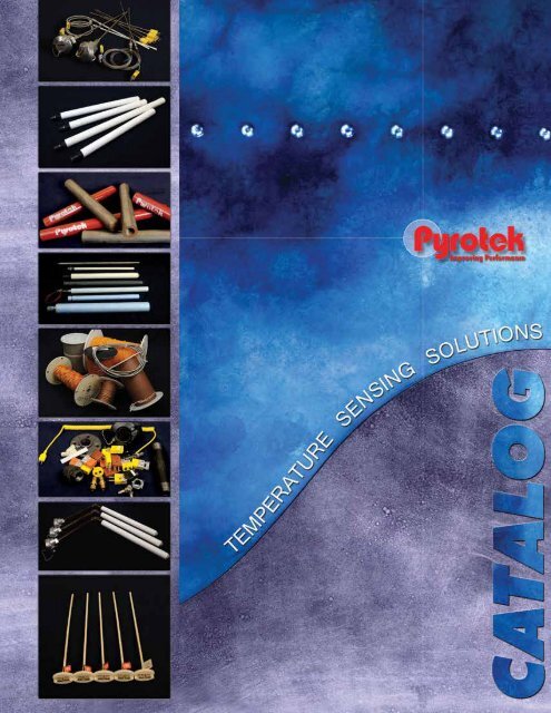
Thermocouple Catalog (North America) - English - Pyrotek
Thermocouple Catalog (North America) - English - Pyrotek
Thermocouple Catalog (North America) - English - Pyrotek

Create successful ePaper yourself
Turn your PDF publications into a flip-book with our unique Google optimized e-Paper software.
Table of Contents<br />
Introduction...............................................................................................................................................................................3<br />
Selection Guide for Aluminium Smelting and Casting Applications.........................................................................4–5<br />
I Series<br />
I1 Series – Base Metal and Noble Metal TC Elements...............................................................................................6<br />
IA Series – Angle Base Metal TC Element..................................................................................................................7<br />
IP Series – Metal Alloy Protection Tubes....................................................................................................................8<br />
I2 Series – Base Metal Elements Protection Tube Style.............................................................................................9<br />
I3 Series – Angle Base Metal TC or Noble Metal TC Elements................................................................................10<br />
I4 Series – MgO, Base Metal TC or Noble Metal TC Elements................................................................................. 11<br />
I5 Series – Straight MgO, Base Metal TC Assemblies: Refractory / Pipe Reinforced Assemblies............................12<br />
I6 Series – Angled MgO, Base Metal TC Assemblies: Refractory / Pipe Reinforced Assemblies.............................13<br />
I7 Series – Straight MgO, Base Metal TC Assemblies: Refractory Tube Assemblies...............................................14<br />
I8 Series – Angled MgO, Base Metal TC Assemblies: Refractory Tube Assemblies.................................................15<br />
I9 Series – Straight MgO, Base Metal TC Assemblies: Cast Iron and Enameled Cast Iron......................................16<br />
I10 Series – Angled MgO, Base Metal TC Assemblies: Cast Iron and Enameled Cast Iron.....................................17<br />
T Series<br />
T1 Series – <strong>Thermocouple</strong> Protection Tubes (O’-Sialon, Sialon, Pinnacle, RFM and SiC)......................................18<br />
T2 Series – <strong>Thermocouple</strong> Protection Tubes (Plain and Red Enameled Cast Iron).................................................19<br />
M Series<br />
M1 Series – Mineral Insulated <strong>Thermocouple</strong> Elements...........................................................................................20<br />
M2 Series – Mineral Insulated Elements Plug and Jack Style..................................................................................21<br />
M3 Series – Mineral Insulated Elements Head and Block Style...............................................................................22<br />
M4 Series – Mineral Insulated <strong>Thermocouple</strong>s with Lead Wire................................................................................23<br />
P Series<br />
P1 Series – General Application Die <strong>Thermocouple</strong>s...............................................................................................24<br />
P2 Series – Spring Adjustable Bayonet Style............................................................................................................25<br />
P3 Series – Armor Adjustable Bayonet Style............................................................................................................26<br />
P4 Series – <strong>Thermocouple</strong> Extensions.....................................................................................................................27<br />
A Series<br />
A1 Series – <strong>Thermocouple</strong> Accessories....................................................................................................................28<br />
A2 Series – Insulated <strong>Thermocouple</strong> Wire & Quick Tip <strong>Thermocouple</strong>s...................................................................29<br />
General Technical References and Tables<br />
<strong>Thermocouple</strong> Protection Tubes.........................................................................................................................30–32<br />
TCPT Matrix..............................................................................................................................................................33<br />
Letter of Calibration...................................................................................................................................................34<br />
Table 1 – Tolerances on Initial Values of EMF vs Temperature for <strong>Thermocouple</strong>s..................................................35<br />
Table 2 – Suggested Upper Temperature Limits for Protected <strong>Thermocouple</strong>s........................................................36<br />
<strong>Thermocouple</strong> Elements, Junctions and Sheaths...............................................................................................37–38<br />
Table 3 – United States Color Codes for Single and Duplex Insulated <strong>Thermocouple</strong> Wire.....................................39<br />
Table 4 – IEC Color Codes for Insulated <strong>Thermocouple</strong> Wire and Extension Materials...........................................40<br />
Temperature Conversion Table.................................................................................................................................41<br />
Inch to Metric Conversion Table................................................................................................................................42<br />
Glossary of Terms...............................................................................................................................................43–45<br />
PYROTEK INC.<br />
Page Revision: OCT-13-EL-1128<br />
www.pyrotek.info/thermocouples • email: info@pyrotek.info Page 2
INTRODUCTION<br />
<strong>Pyrotek</strong> is a leading international company supplying aluminium, foundry, glass, zinc, steel, sound and hearth customers with performance-improving<br />
technical products, integrated processing systems and consulting services worldwide. Our mission is to provide innovative<br />
solutions to customer needs utilizing our global resources.<br />
<strong>Pyrotek</strong> offers a complete line of thermocouple elements, protective tubes and assemblies for molten metal applications. <strong>Thermocouple</strong><br />
elements must be protected from atmospheres that are not compatible with thermocouple alloys. <strong>Thermocouple</strong> protection tubes (TCPT)<br />
guard their elements against corrosion by providing a shield from the harmful surroundings. Proper TCPT should be selected based on<br />
several factors: exposed temperatures and heating rates, number of temperature cycles, mechanical movements, chemical and / or alloy<br />
contents, and applications. <strong>Pyrotek</strong> offers a wide variety of TCPTs for almost every high temperature application; from cast iron (plain or<br />
enameled), reinforced fiberglass material (RFM ® ) and high performance ceramics, to standard refractory types.<br />
Our global sales engineers are trained to assist in selecting the correct temperature measuring solution for your typical and custom<br />
specific application or process. <strong>Pyrotek</strong> stocks a wide variety of thermocouple protection tubes, combined with an extensive range of<br />
elements. We provide a total solution for all your temperature-measuring needs. Together, with 60+ years in thermocouple experience<br />
and <strong>Pyrotek</strong>’s global team of engineering and technical specialists, we can improve your manufacturing process.<br />
<strong>Pyrotek</strong> is committed to:<br />
· Customer Satisfaction · Profitable Growth<br />
· Integrity · Employee Development<br />
· Reliability, Quality and Service · Partnerships with Customers and Suppliers<br />
· Environmental Awareness<br />
PYROTEK INC.<br />
Page Revision: OCT-13-EL-1128<br />
www.pyrotek.info/thermocouples • email: info@pyrotek.info Page 3
SELECTION GUIDE FOR ALUMINIUM SMELTING AND CASTING APPLICATIONS<br />
MELTING AND HOLDING FURNACE<br />
There are various types of melting furnaces used in the aluminium industry. Today’s most common furnaces are reverbatory or “Reverb”<br />
furnaces. These furnaces have a common chamber for the products of combustion and metal charge. Immersion TCPT assemblies are<br />
utilized to monitor and control the temperature of the liquid metal in melt preparation, holding, degassing and casting operations. Typical<br />
installations have mechanical extractors that pull the complete TCPT assembly out of the melting furnace during charging and high fire.<br />
Some assemblies have two thermocouple elements of different lengths to monitor temperatures at two critical depths. A feedback loop<br />
may be used to modify the heat energy input to achieve optimal metal temperatures.<br />
Application Conditions<br />
• Direct molten aluminium immersion<br />
• Exposed to typical aluminium melting temperature range<br />
• Maximum mechanical impacts from metal charges<br />
• Maximum mechanical impacts from maintenance<br />
Recommended TCPT Type and Assemblies<br />
Use plain or enamel cast iron straight series:<br />
go to I9 series with type K<br />
Example: I9-MIK-CIP60-01-CI-00<br />
Use plain or enamel cast iron angled series:<br />
go to I6 series with type K, use CIP or CIR in slot #4<br />
Example: I6-MIK-CIP-24-12-41<br />
Application Conditions<br />
• Direct molten aluminium immersion<br />
• Non-wetting to aluminium and its alloys<br />
• Less dross buildup at metal line<br />
• Excellent thermal shock resistance<br />
• Pipe reinforced assembly<br />
Recommended TCPT Type and Assemblies<br />
Use RFM series:<br />
go to I5 series for straight TCPT assemblies<br />
Example: I5-MIK-RFM-24-00-12-21-C<br />
go to I6 series for angled TCPT assemblies<br />
Example: I6-MIK-RFM-24-12-41<br />
Use Pinnacle series:<br />
go to I5 series for straight TCPT assemblies<br />
Example: I5-MIK-PIN-24-00-12-21-C<br />
go to I6 series for angled TCPT assemblies<br />
Example: I6-MIK-PIN-24-12-41<br />
Application Conditions<br />
• Direct molten aluminium immersion<br />
• Pressurized chamber containing molten aluminium<br />
• Non-wetting to aluminium and its alloys<br />
• Corrosion resistance<br />
• High performance ceramic<br />
• Less dross buildup at metal line<br />
• Excellent thermal shock resistance<br />
Recommended TCPT Type and Assemblies<br />
Use O’-Sialon series:<br />
go to I7 series for straight TCPT assemblies<br />
Example: I7-MIK-OSI-70-41<br />
go to I8 series for angled TCPT assemblies<br />
Example: I8-MIK-OSI-90-12-00-6-21-H<br />
Use SiN/Sialon series:<br />
go to I7 series for straight TCPT assemblies<br />
Example: I7-MIK-SIA-70-41<br />
go to I8 series for angled TCPT assemblies<br />
Example: I8-MIK-SIA-90-12-00-6-21-H<br />
THERMOCOUPLE EXTENSIONS, WIRE, ACCESSORIES AND QUICK TIP<br />
A wide variety of TC extensions and accessories are available to connect to the instrumentation or control panels. Often, extensions<br />
are used to extend the length of the thermocouple to reduce waste and the replacement of sensor lead wire. Many parts are typically<br />
available from stock and many other options are available upon request.<br />
Recommended TC Assemblies<br />
<strong>Thermocouple</strong> extensions:<br />
go to P4 series<br />
Insulated thermocouple wire and quick tip:<br />
go to A2 series<br />
<strong>Thermocouple</strong> accessories:<br />
go to A1 series<br />
PYROTEK INC.<br />
Page Revision: OCT-13-EL-1128<br />
www.pyrotek.info/thermocouples • email: info@pyrotek.info Page 4
SELECTION GUIDE FOR ALUMINIUM SMELTING AND CASTING APPLICATIONS<br />
BASE METAL OR INDUSTRIAL THERMOCOUPLE<br />
If application requires installations of industrial type thermocouples on-site, <strong>Pyrotek</strong> offers various configurations and designs. All base<br />
metal thermocouple assemblies are available in ASTM E230 types K and J, can be twisted or butt welded.<br />
Recommended TC Assemblies<br />
For basic metal TC elements with no connectors:<br />
Base elements:<br />
go to I1 series<br />
Example I1-11KVT-24<br />
Noble elements:<br />
go to I1 series<br />
Example I1-24R-24<br />
Base metal angled TC element with no connectors:<br />
go to IA series<br />
Example IA-11JVT-36-12<br />
CARBON BAKE<br />
Carbon baking furnaces are used to bake carbon anodes and cathode blocks, preparing them for use in the reduction cells (pots) of<br />
primary aluminium plants. A carbon bake furnace is made up of a number of hollow flue walls arranged to form pits for baking anodes.<br />
Once the pits are prepared and loaded, the anodes are ready to be heated or baked. To properly control firing and cooling cycles, choosing<br />
the right thermocouple element and protection tube is critical.<br />
Application Conditions<br />
• No direct molten aluminium immersion, installed in preheat,<br />
flue and pit walls<br />
• Exposed to heated gasses in severe corrosive atmospheres<br />
• Highest temperature range at 2156–2228°F (1180–1220°C),<br />
close to firing frames<br />
• Minimal to no mechanical impact<br />
• Minimal to no maintenance cleaning<br />
Recommended TCPT Type and Assemblies<br />
In preheat sections:<br />
go to M2 series, type K<br />
Example: M2-K1L60U-44-FCZ-21L<br />
In flue and pit sections:<br />
go to M2 series, type N<br />
Example: M2-N1L50U-44-FCZ-21L<br />
In all sections INCONEL ® 601 TCPT type:<br />
go to IP series, INCONEL type<br />
Example: IP-C-61-44-FX<br />
Recommended TC Element Extensions<br />
Connecting from TCPT to control ports:<br />
go to P4 series<br />
MOLDS METAL CASTING<br />
Die thermocouples are used in all aluminium casting molds. Casting molds come in various shapes and forms; some are temporary and<br />
others are permanent. <strong>Pyrotek</strong> provides die thermocouples with compression fittings or bayonet adapters for quick attachment to tooling<br />
and dies. Special constructions and designs are available upon request.<br />
Application Conditions<br />
• Die molds at temperatures up to 1600°F (870°C)<br />
• Bayonet adapter or compression fitting for quick connection<br />
• Spring adjustable style<br />
• Fiberglass insulated thermocouple elements<br />
• Armor adjustable style<br />
Recommended TC Assemblies<br />
General die thermocouple: go to P1 series<br />
Spring adjustable bayonet: go to P2 series<br />
Armor adjustable bayonet: go to P3 series<br />
Continued next page<br />
PYROTEK INC.<br />
Page Revision: OCT-13-EL-1128<br />
www.pyrotek.info/thermocouples • email: info@pyrotek.info Page 5
I1 SERIES – BASE METAL AND NOBLE METAL TC ELEMENTS<br />
<strong>Pyrotek</strong>’s straight base metal (K and J) and noble metal (R, S, and B) thermocouple elements are for typical protection tube<br />
assemblies utilized in industrial applications. Special construction styles may be available upon request.<br />
Base Metal Element<br />
I1<br />
—<br />
2 3 4 5 6<br />
—<br />
2-WIRE AWG<br />
Order Code<br />
8<br />
11<br />
14<br />
3-THERMOCOUPLE CALIBRATION<br />
Order Code<br />
J<br />
K<br />
JJ<br />
KK<br />
Description<br />
8 AWG (0.128 Inches)<br />
11 AWG (0.091 Inches)<br />
14 AWG (0.064 Inches)<br />
Description<br />
Type J<br />
Type K<br />
Dual Type J<br />
Dual Type K<br />
Other calibrations available upon request.<br />
6-ELEMENT LENGTH IN INCHES “L” DIMENSION<br />
Order Code<br />
XX<br />
5-WELD JUNCTION STYLE<br />
Order Code<br />
S<br />
T<br />
4-INSULATOR TYPE<br />
Order Code<br />
R<br />
N<br />
V<br />
For fractional lengths, specify as follows.<br />
Example: 12(1/2) for 12-½ inch<br />
Description<br />
Butt Weld<br />
Twist and Weld (Standard)<br />
Description<br />
Round Insulators<br />
No Insulators; Bare Element Only<br />
Oval Insulators<br />
Noble Metal Element<br />
I1<br />
—<br />
2 3 4 5<br />
—<br />
2-WIRE AWG<br />
Order Code<br />
24<br />
26<br />
Description<br />
24 AWG (0.020 Inches)<br />
26 AWG (0.016 Inches)<br />
5-ELEMENT LENGTH IN INCHES “L” DIMENSION<br />
Order Code<br />
XX<br />
For fractional lengths, specify as follows.<br />
Example: 12(1/2) for 12-½ inch<br />
3-THERMOCOUPLE CALIBRATION<br />
Order Code<br />
R<br />
S<br />
B<br />
Description<br />
Type R<br />
Type S<br />
Type B<br />
4-INSULATOR TYPE<br />
Order Code<br />
N<br />
R<br />
Description<br />
No Insulators; Bare Element Only<br />
Round Solid Insulator<br />
PYROTEK INC.<br />
Page Revision: OCT-13-EL-1128<br />
www.pyrotek.info/thermocouples • email: info@pyrotek.info Page 6
IA SERIES – ANGLE BASE METAL TC ELEMENT<br />
<strong>Pyrotek</strong>’s angle base metal thermocouples are elements for typical angle assemblies utilized in industrial applications.<br />
Special construction styles may be available upon request.<br />
2 3 4 5 6 7<br />
IA —<br />
V — —<br />
2-WIRE AWG<br />
Order Code<br />
8<br />
11<br />
14<br />
3-THERMOCOUPLE CALIBRATION<br />
Order Code<br />
J<br />
K<br />
JJ<br />
KK<br />
Description<br />
8 AWG (0.128 Inches)<br />
11 AWG (0.091 Inches)<br />
14 AWG (0.064 Inches)<br />
Description<br />
Type J<br />
Type K<br />
Dual Type J<br />
Dual Type K<br />
Other calibrations available upon request.<br />
7-COLD LEG LENGTH IN INCHES “CL” DIMENSION<br />
Order Code<br />
XX<br />
For fractional lengths, specify as follows.<br />
Example: 12(1/2) for 12-½ inch<br />
6-HOT LEG LENGTH IN INCHES “HL” DIMENSION<br />
Order Code<br />
XX<br />
5-WELD JUNCTION STYLE<br />
Order Code<br />
S<br />
T<br />
For fractional lengths, specify as follows.<br />
Example: 12(1/2) for 12-½ inch<br />
Description<br />
Butt Weld<br />
Twist and Weld (Standard)<br />
4-INSULATOR TYPE<br />
Order Code<br />
V<br />
Description<br />
Oval Insulators<br />
PYROTEK INC.<br />
Page Revision: OCT-13-EL-1128<br />
www.pyrotek.info/thermocouples • email: info@pyrotek.info Page 7
IP SERIES – METAL ALLOY PROTECTION TUBES<br />
Metal alloy protection tubes are replacement tubes for thermocouple assemblies. These tubes are for general purpose<br />
industrial applications. Special materials and sizes available upon request.<br />
2 3 4 5 5.1<br />
IP — — — —<br />
2-PIPE SIZE<br />
Order Code<br />
C<br />
D<br />
Description<br />
1/2 Inch NPT Sch40<br />
3/4 NPT Sch40<br />
Other sizes available on request.<br />
3-PROTECTION TUBE MATERIAL<br />
Order Code<br />
34<br />
36<br />
30<br />
61<br />
Description<br />
304SS<br />
316SS<br />
310SS<br />
INCONEL 601<br />
5.1-INSERTION LENGTH “U” DIMENSION<br />
Order Code<br />
XX<br />
5-OPTIONAL MOUNTING CHOICES<br />
Order Code<br />
00<br />
FX<br />
FD<br />
FE<br />
GD<br />
GE<br />
For fractional lengths, specify as follows.<br />
Example: 12(1/2) for 12-½ Inches<br />
Description<br />
No optional fitting<br />
Adjustable Flange with Set Screw<br />
Welded SS Bushing 3/4 Inch NPT Thread<br />
Welded SS Bushing 1 Inch NPT Thread<br />
Welded Steel Bushing 3/4 Inch NPT Thread<br />
Welded Steel Bushing 1 Inch NPT Thread<br />
4-TUBE LENGTH IN INCHES “L” DIMENSION<br />
Order Code<br />
XX<br />
For fractional lengths, specify as follows.<br />
Example: 12(1/2) for 12-½ Inches<br />
PYROTEK INC.<br />
Page Revision: OCT-13-EL-1128<br />
www.pyrotek.info/thermocouples • email: info@pyrotek.info Page 8
I2 SERIES – BASE METAL ELEMENTS PROTECTION TUBE STYLE<br />
<strong>Pyrotek</strong>’s metal protection tube style assemblies are most commonly utilized in medium to high temperature industrial<br />
applications. Roof sensors, boiler temperatures, heat treatment and other industrial applications are typical. Special<br />
protection tube materials and construction styles are available upon request.<br />
I2<br />
2 3 4 5 6 7 8 9 9.1 10<br />
— V — — —<br />
—<br />
2-WIRE AWG<br />
Order Code<br />
8<br />
11<br />
14<br />
MI<br />
4-INSULATOR TYPE<br />
Order Code<br />
V<br />
Description<br />
Oval Insulators<br />
If using option MI from box 2 skip this option.<br />
5-WELD JUNCTION STYLE<br />
Order Code<br />
S<br />
T<br />
Description<br />
8 AWG (0.128 Inches)<br />
11 AWG (0.091 Inches)<br />
14 AWG (0.064 Inches)<br />
3/16 Inch Diameter I600<br />
Ungrounded MgO Element<br />
3-THERMOCOUPLE CALIBRATION<br />
Order Code<br />
J<br />
K<br />
N<br />
JJ<br />
KK<br />
NN<br />
Description<br />
Type J<br />
Type K<br />
Type N<br />
Dual Type J<br />
Dual Type K<br />
Dual Type N<br />
Other calibrations available upon request.<br />
Description<br />
Butt Weld<br />
Twist and Weld (Standard)<br />
If using option MI from box 2 skip this option.<br />
6-PIPE SIZE<br />
Order Code<br />
C<br />
D<br />
Description<br />
1/2 Inch NPT Sch40<br />
3/4 NPT Sch40<br />
Other sizes available on request.<br />
10-SCREW COVER HEAD STYLE<br />
Order Code<br />
00<br />
41<br />
42<br />
9-OPTIONAL MOUNTING CHOICES<br />
Order Code<br />
00<br />
FX<br />
FD<br />
FE<br />
GD<br />
GE<br />
Description<br />
No Head and Block<br />
Cast Aluminium Screw Cover Head<br />
Cast Iron Screw Cover Head<br />
Description<br />
No optional fitting<br />
Adjustable Flange with Set Screw<br />
Welded SS Bushing 3/4 Inch NPT Thread<br />
Welded SS Bushing 1 Inch NPT Thread<br />
Welded Steel Bushing 3/4 Inch NPT Thread<br />
Welded Steel Bushing 1 Inch NPT Thread<br />
7-PROTECTION TUBE MATERIAL<br />
Order Code<br />
34<br />
36<br />
30<br />
61<br />
9.1-INSERTION LENGTH IN WHOLE INCHES<br />
Order Code<br />
XX<br />
Description<br />
304SS<br />
316SS<br />
310SS<br />
INCONEL 601<br />
Example: GD09 for a 9 Inch U<br />
Dimension<br />
8-TUBE LENGTH IN INCHES “L” DIMENSION<br />
Order Code<br />
XX<br />
For fractional lengths, specify as follows.<br />
Example: 12(1/2) for 12-½ Inches<br />
PYROTEK INC.<br />
Page Revision: OCT-13-EL-1128<br />
www.pyrotek.info/thermocouples • email: info@pyrotek.info Page 9
I3 SERIES – ANGLE BASE METAL TC OR NOBLE METAL TC ELEMENTS<br />
<strong>Pyrotek</strong>’s angle metal protection tube style assemblies are most commonly utilized in medium to high temperature industrial<br />
applications. Special protection tube materials and construction styles are available upon request.<br />
I3<br />
2 3 4 5 6 7 8 9 10 10.1 11<br />
— V — — — — —<br />
2-WIRE AWG<br />
Order Code<br />
8<br />
11<br />
14<br />
MI<br />
Description<br />
8 AWG (0.128 Inches)<br />
11 AWG (0.091 Inches)<br />
14 AWG (0.064 Inches)<br />
3/16 Inch Diameter<br />
I600 Ungrounded MgO<br />
Element<br />
3-THERMOCOUPLE CALIBRATION<br />
Order Code<br />
K<br />
N<br />
KK<br />
NN<br />
5-WELD JUNCTION STYLE<br />
Order Code<br />
S<br />
T<br />
Description<br />
Type K<br />
Type N<br />
Dual Type K<br />
Dual Type N<br />
Other calibrations are available upon request.<br />
4-INSULATOR TYPE<br />
Order Code<br />
V<br />
Description<br />
Oval Insulators<br />
If using option MI from box 2 skip this option.<br />
Description<br />
Butt Weld<br />
Twist and Weld (Standard)<br />
If using option MI from box 2 skip this option.<br />
11-SCREW COVER HEAD STYLE<br />
Order Code<br />
00<br />
41<br />
42<br />
10-OPTIONAL MOUNTING CHOICES<br />
Order Code<br />
00<br />
FX<br />
FD<br />
FE<br />
GD<br />
GE<br />
Description<br />
No Head and Block<br />
Cast Aluminium Screw<br />
Cover Head<br />
Cast Iron Screw Cover<br />
Head<br />
10.1-INSERTION LENGTH IN WHOLE INCHES<br />
Order Code<br />
XX<br />
Example: GD09 for a 9 Inch U<br />
Dimension<br />
Description<br />
No optional fitting<br />
Adjustable Flange with Set Screw<br />
Welded SS Bushing 3/4 Inch NPT Thread<br />
Welded SS Bushing 1 Inch NPT Thread<br />
Welded Steel Bushing 3/4 Inch NPT Thread<br />
Welded Steel Bushing 1 Inch NPT Thread<br />
9-COLD LENGTH IN WHOLE INCHES (STEEL PIPE EXTENSION)<br />
Order Code<br />
XX<br />
For fractional lengths, specify as follows.<br />
Example: 12(1/2) for 12-½ Inches<br />
8-HOT LEG LENGTH IN WHOLE INCHES<br />
Order Code<br />
XX<br />
For fractional lengths, specify as follows.<br />
Example: 12(1/2) for 12-½ Inches<br />
6-PIPE SIZE<br />
Order Code<br />
C<br />
D<br />
Description<br />
1/2 Inch NPT Sch40<br />
3/4 Inch NPT Sch40<br />
7-PROTECTION TUBE MATERIAL<br />
Order Code<br />
34<br />
36<br />
30<br />
61<br />
Description<br />
304SS<br />
316SS<br />
310SS<br />
INCONEL 601<br />
PYROTEK INC.<br />
Page Revision: OCT-13-EL-1128<br />
www.pyrotek.info/thermocouples • email: info@pyrotek.info Page 10
I4 SERIES – MgO, BASE METAL TC OR NOBLE METAL TC ELEMENTS<br />
<strong>Pyrotek</strong>’s ceramic protection tube assemblies are typically utilized in temperatures exceeding 2200°F (1204°C). The noble<br />
metal elements offer the advantages of handling higher temperatures and providing greater accuracy than base metal elements.<br />
I4<br />
2 3 4 5 6 6.1 7<br />
— — —<br />
—<br />
2-WIRE AWG<br />
Order Code<br />
MI<br />
8<br />
11<br />
14<br />
24<br />
26<br />
Description<br />
3/16 Inch Diameter I600<br />
Ungrounded MgO Element<br />
8 AWG (0.128 Inches)<br />
11 AWG (0.091 Inches)<br />
14 AWG (0.064 Inches)<br />
24 AWG (0.020 Inches)<br />
26 AWG (0.016 Inches)<br />
3-THERMOCOUPLE CALIBRATION<br />
Order Code<br />
K<br />
N<br />
R<br />
S<br />
KK<br />
NN<br />
RR<br />
SS<br />
Description<br />
Type K<br />
Type N<br />
Type R<br />
Type S<br />
Dual Type K<br />
Dual Type N<br />
Dual Type R<br />
Dual Type S<br />
Other calibrations available upon request.<br />
4-CERAMIC PROTECTION TUBE TYPE<br />
Order Code<br />
M<br />
A<br />
Description<br />
Mullite<br />
Alumina<br />
Type<br />
Type K & J Only<br />
Type K Only<br />
Type K Only<br />
Type K Only<br />
Type R & S Only<br />
Type R & S Only<br />
7-SCREW COVER HEAD<br />
Order Code<br />
00<br />
41<br />
42<br />
6.1-OPTIONS<br />
Order Code<br />
FX<br />
Description<br />
No Head and Block<br />
Cast Aluminium Screw Cover Head<br />
Cast Iron Screw Cover Head<br />
Description<br />
Adjustable Flange with Set Screw<br />
6-TUBE LENGTH IN INCHES “L” DIMENSION<br />
Order Code<br />
XX<br />
For fractional lengths, specify as follows.<br />
Example: 12(1/2) for 12-½ inch<br />
5-CERAMIC PROTECTION TUBE DIAMETER AND FITTINGS<br />
Order Code Description and Order Instructions ID OD Process Thread Termination Thread<br />
LC Steel Close Nipple 1/4 Inch 3/8 Inch 1/2 Inch NPT 1/2 Inch NPT<br />
L(X) Steel Pipe Nipple (Specify “X” Dimension) 1/4 Inch 3/8 Inch 1/2 Inch NPT 1/2 Inch NPT<br />
LH Steel Hex Nipple 1/4 Inch 3/8 Inch 1/2 Inch NPT 1/2 Inch NPT<br />
NC Steel Close Nipple 7/16 Inch 11/16 Inch 3/4 Inch NPT 3/4 Inch NPT<br />
N(X) Steel Pipe Nipple (Specify “X” Dimension) 7/16 Inch 11/16 Inch 3/4 Inch NPT 3/4 Inch NPT<br />
NH Steel Hex Nipple 7/16 Inch 11/16 Inch 3/4 Inch NPT 1/2 Inch NPT<br />
PC Steel Close Nipple 1/2 Inch 3/4 Inch 3/4 Inch NPT 3/4 Inch NPT<br />
P(X) Steel Pipe Nipple (Specify “X” Dimension) 1/2 Inch 3/4 Inch 3/4 Inch NPT 3/4 Inch NPT<br />
PH Steel Hex Nipple 1/2 Inch 3/4 Inch 3/4 Inch NPT 1/2 Inch NPT<br />
QC Steel Close Nipple 5/8 Inch 7/8 Inch 1 Inch NPT 1 Inch NPT<br />
Q(X) Steel Pipe Nipple (Specify “X” Dimension) 5/8 Inch 7/8 Inch 1 Inch NPT 1 Inch NPT<br />
QH Steel Hex Nipple 5/8 Inch 7/8 Inch 1 Inch NPT 3/4 Inch NPT<br />
PYROTEK INC.<br />
Page Revision: OCT-13-EL-1128<br />
www.pyrotek.info/thermocouples • email: info@pyrotek.info Page 11
I5 SERIES – STRAIGHT MgO, BASE METAL TC ASSEMBLIES:<br />
REFRACTORY / PIPE REINFORCED ASSEMBLIES<br />
<strong>Pyrotek</strong>’s refractory / pipe reinforced assemblies are typically utilized in applications such as holding, melting and laundering<br />
of molten aluminium. They provide non-wetting attributes, extended life and a steel inner tube that provides support for<br />
strength and assembly mounting options.<br />
Figure A<br />
Figure B<br />
2 3 4 5 6 7 8 8.1<br />
I5 —<br />
— — — — —<br />
2-WIRE AWG<br />
Order Code<br />
MI<br />
8<br />
11<br />
14<br />
4-THERMOCOUPLE PROTECTION TUBE MATERIAL<br />
Order Code Description Standard Stocked Lengths<br />
RFM<br />
Description<br />
3/16 Inch Diameter 304SS<br />
Ungrounded MgO Element<br />
8 AWG (0.128 Inches)<br />
11 AWG (0.091 Inches)<br />
14 AWG (0.064 Inches)<br />
3-THERMOCOUPLE CALIBRATION<br />
Order Code<br />
K<br />
KK<br />
Description<br />
Type K<br />
Dual Type K<br />
Other calibrations available upon request.<br />
Reinforced Fiberglass<br />
Material TC Protection Tube<br />
PIN Pinnacle Cast O’-Sialon /<br />
Silicon Carbide Protection<br />
Tube<br />
Type<br />
Type K<br />
Type K<br />
Type K<br />
Type K<br />
12, 18, 24, 30, 36, 48 Inches<br />
Special lengths are available.<br />
6, 12, 18, 24, 30, 36, 48 Inches<br />
Special lengths are available.<br />
RSC SiC-Graphite Protection Tube 12, 18, 24, 30, 36, 48 Inches<br />
5-TUBE LENGTH IN WHOLE INCHES “L” DIMENSION<br />
Order Code<br />
XX<br />
For length order code, insert whole inch dimension from<br />
Box 4. Example: 18 for 18 Inch Tube Length<br />
7-EXTENSION LENGTH IN WHOLE INCHES “X” DIMENSION<br />
Order Code<br />
XX<br />
6- SCREW COVER HEAD OR EXTENSION<br />
Order Code<br />
41<br />
42<br />
8.1-SHEATH TERMINATION OPTIONS<br />
Order Code<br />
M<br />
H<br />
C<br />
8-SHEATH TERMINATION<br />
Order Code<br />
21<br />
22<br />
23<br />
24<br />
Insert length in whole inches. For fractional<br />
length, specify as follows.<br />
Example: 12(1/2) for 12-½ Inches<br />
Description<br />
Cast Aluminium<br />
Cast Iron<br />
Description<br />
Medium Temperature Connectors<br />
500°F (260°C)<br />
High Temperature Connectors<br />
800°F (427°C)<br />
Compression Tube Adaptor<br />
Holding Plug to Sheath<br />
Only add option designation letter if those options are<br />
desired.<br />
Description<br />
Standard Male Plug<br />
Standard Female Jack<br />
Standard Plug / Jack<br />
Standard Solid Pin Plug<br />
The temperature rating for all standard temperature<br />
plugs is 425°F (218°C).<br />
00 MI Cable Extension Beyond<br />
<strong>Thermocouple</strong> Protection Tube*<br />
Figure A<br />
Figure B<br />
*For MI Cable Extension Option (Figure B), continue building part<br />
number using boxes 7, 8 and 8.1.<br />
PYROTEK INC.<br />
Page Revision: OCT-13-EL-1128<br />
www.pyrotek.info/thermocouples • email: info@pyrotek.info Page 12
I6 SERIES – ANGLED MgO, BASE METAL TC ASSEMBLIES:<br />
REFRACTORY / PIPE REINFORCED ASSEMBLIES<br />
<strong>Pyrotek</strong>’s refractory / pipe reinforced assemblies are typically utilized in applications such as holding, melting and laundering<br />
of molten aluminium. They provide non-wetting attributes, extended life and a steel inner tube that provides support for<br />
strength and assembly mounting options.<br />
Figure A<br />
Figure B<br />
2 3 4 5 6 7 8 9 9.1<br />
I6 — — — — — — —<br />
2-WIRE AWG<br />
Order Code<br />
MI<br />
8<br />
11<br />
14<br />
4-THERMOCOUPLE PROTECTION TUBE MATERIAL<br />
Order Code Description Standard Stocked Lengths<br />
RFM<br />
Description<br />
3/16 Inch Diameter 304SS<br />
Ungrounded MgO Element<br />
8 AWG (0.128 Inches)<br />
11 AWG (0.091 Inches)<br />
14 AWG (0.064 Inches)<br />
3-THERMOCOUPLE CALIBRATION<br />
Order Code<br />
K<br />
KK<br />
Description<br />
Type K<br />
Dual Type K<br />
Other calibrations available upon request.<br />
Reinforced Fiberglass<br />
Material TC Protection Tube<br />
PIN Pinnacle Cast O’-Sialon /<br />
Silicon Carbide Protection<br />
Tube<br />
Type<br />
Type K<br />
Type K<br />
Type K<br />
Type K<br />
12, 18, 24, 30, 36, 48 Inches<br />
Special lengths are available.<br />
6, 12, 18, 24, 30, 36, 48 Inches<br />
Special lengths are available.<br />
RSC SiC Protection Tube 12, 18, 24, 30, 36, 48 Inches<br />
5-HOT LENGTH IN WHOLE INCHES “L” DIMENSION<br />
Order Code<br />
XX<br />
For length order code, insert whole inch dimension from<br />
Box 4. Example: 18 for 18 Inch Tube Length<br />
6-COLD LENGTH IN WHOLE INCHES (STEEL PIPE EXTENSION)<br />
Order Code<br />
XX<br />
For fractional lengths, specify as follows.<br />
Example: 12(1/2) for 12-½ Inches<br />
8-EXTENSION LENGTH IN WHOLE INCHES “X” DIMENSION<br />
Order Code<br />
XX<br />
7- SCREW COVER HEAD OR EXTENSION<br />
Order Code<br />
41<br />
42<br />
9.1-SHEATH TERMINATION OPTIONS<br />
Order Code<br />
M<br />
H<br />
C<br />
9-SHEATH TERMINATION<br />
Order Code<br />
21<br />
22<br />
23<br />
24<br />
Insert length in whole inches. For fractional<br />
lengths, specify as follows.<br />
Example: 12(1/2) for 12-½ Inches<br />
Description<br />
Cast Aluminium<br />
Cast Iron<br />
Description<br />
Medium Temperature Connectors<br />
500°F (260°C)<br />
High Temperature Connectors<br />
800°F (427°C)<br />
Compression Tube Adaptor<br />
Holding Plug to Sheath<br />
Only add option designation letter if those options are<br />
desired.<br />
Description<br />
Standard Male Plug<br />
Standard Female Jack<br />
Standard Plug / Jack<br />
Standard Solid Pin Plug<br />
The temperature rating for all standard temperature<br />
plugs is 425°F (218°C).<br />
00 MI Cable Extension Beyond<br />
<strong>Thermocouple</strong> Protection Tube*<br />
Figure A<br />
Figure B<br />
*For MI Cable Extension Option (Figure B), continue building part<br />
number using boxes 7, 8, 9, and 9.1.<br />
PYROTEK INC.<br />
Page Revision: OCT-13-EL-1128<br />
www.pyrotek.info/thermocouples • email: info@pyrotek.info Page 13
I7 SERIES – STRAIGHT MgO, BASE METAL TC ASSEMBLIES:<br />
REFRACTORY TUBE ASSEMBLIES<br />
<strong>Pyrotek</strong>’s refractory tube assemblies are typically utilized in applications such as holding, melting and laundering of molten<br />
aluminium. These assemblies provide non-wetting attributes, as well as higher life expectancy in applications with limited<br />
impact from solids.<br />
Figure A<br />
Figure B<br />
2 3 4 5 6 7 8 8.1<br />
I7 — — — — — —<br />
2-WIRE AWG<br />
Order Code<br />
MI<br />
8<br />
11<br />
14<br />
3-THERMOCOUPLE CALIBRATION<br />
Order Code<br />
K<br />
KK<br />
4-THERMOCOUPLE PROTECTION TUBE MATERIAL<br />
Order Code Description Standard Stocked Lengths<br />
OSI Extruded O’-Sialon /<br />
Silicon Carbide Protection<br />
Tube, 28 mm x 16 mm ID<br />
SIA<br />
Description<br />
Type K<br />
Dual Type K<br />
Other calibrations available upon request.<br />
Extruded Silicon Nitride<br />
<strong>Thermocouple</strong> Protection<br />
Tube, 28 mm x 16 mm ID<br />
5-TUBE LENGTH IN MILLIMETERS “L” DIMENSION<br />
Order Code<br />
30<br />
40<br />
50<br />
60<br />
70<br />
80<br />
90<br />
10<br />
12<br />
Description<br />
3/16 Inch Diameter 304SS<br />
Ungrounded MgO Element<br />
8 AWG (0.128 Inches)<br />
11 AWG (0.091 Inches)<br />
14 AWG (0.064 Inches)<br />
Length<br />
300 mm<br />
400 mm<br />
500 mm<br />
600 mm<br />
700 mm<br />
800 mm<br />
900 mm<br />
1000 mm<br />
1200 mm<br />
Type<br />
Type K<br />
Type K<br />
Type K<br />
Type K<br />
300, 400, 500, 600, 700, 800,<br />
900, 1000 and 1200 mm<br />
400, 500, 600, 700, 800, 900<br />
and 1000 mm<br />
7-EXTENSION LENGTH IN WHOLE INCHES X DIMENSION<br />
Order Code<br />
XX<br />
6- SCREW COVER HEAD OR EXTENSION<br />
Order Code<br />
41<br />
42<br />
8.1-SHEATH TERMINATION OPTIONS<br />
Order Code<br />
M<br />
H<br />
C<br />
8-SHEATH TERMINATION<br />
Order Code<br />
21<br />
22<br />
23<br />
24<br />
Insert length in whole inches.<br />
For fractional lengths, specify as follows.<br />
Example: 12(1/2) for 12-½ Inches<br />
Description<br />
Cast Aluminium<br />
Cast Iron<br />
Description<br />
Medium Temperature Connectors<br />
500°F (260°C)<br />
High Temperature Connectors<br />
800°F (427°C)<br />
Compression Tube Adaptor<br />
Holding Plug to Sheath<br />
Only add option designation letter if those options are<br />
desired.<br />
Description<br />
Standard Male Plug<br />
Standard Female Jack<br />
Standard Plug / Jack<br />
Standard Solid Pin Plug<br />
The temperature rating for all standard temperature<br />
plugs is 425°F (218°C).<br />
00 MI Cable Extension Beyond<br />
<strong>Thermocouple</strong> Protection Tube*<br />
Figure A<br />
Figure B<br />
*For MI Cable Extension Option (Figure B), continue building part<br />
number using boxes 7, 8 and 8.1.<br />
PYROTEK INC.<br />
Page Revision: OCT-13-EL-1128<br />
www.pyrotek.info/thermocouples • email: info@pyrotek.info Page 14
I8 SERIES – ANGLED MgO, BASE METAL TC ASSEMBLIES:<br />
REFRACTORY TUBE ASSEMBLIES<br />
<strong>Pyrotek</strong>’s refractory tube assemblies can be utilized in applications such as holding, melting and laundering of molten<br />
aluminium. These assemblies provide non-wetting attributes, as well as higher life expectancy in applications where limited<br />
impact from solids would occur.<br />
Figure A<br />
Figure B<br />
2 3 4 5 6 7 8 9 9.1<br />
I8 — — — — — — —<br />
2-WIRE AWG<br />
Order Code<br />
MI<br />
8<br />
11<br />
14<br />
Description<br />
3/16 Inch Diameter 304SS<br />
Ungrounded MgO Element<br />
8 AWG (0.128 Inches)<br />
11 AWG (0.091 Inches)<br />
14 AWG (0.064 Inches)<br />
3-THERMOCOUPLE CALIBRATION<br />
Order Code<br />
K<br />
KK<br />
Description<br />
Type K<br />
Dual Type K<br />
Other calibrations available upon request.<br />
Type<br />
Type K<br />
Type K<br />
Type K<br />
Type K<br />
4-THERMOCOUPLE PROTECTION TUBE MATERIAL<br />
Order Code Description Standard Stocked Lengths<br />
OSI Extruded O’-Sialon /<br />
Silicon Carbide Protection<br />
Tube, 28 mm x 16 mm ID<br />
SIA<br />
Extruded Silicon Nitride<br />
<strong>Thermocouple</strong> Protection<br />
Tube, 28 mm x 16 mm ID<br />
300, 400, 500, 600, 700, 800,<br />
900, 1000 and 1200 mm<br />
400, 500, 600, 700, 800, 900<br />
and 1000 mm<br />
5-TUBE HOT LEG LENGTH IN MILLIMETERS “L” DIMENSION<br />
Order Code<br />
30<br />
40<br />
50<br />
60<br />
70<br />
80<br />
90<br />
10<br />
12<br />
Length<br />
300 mm<br />
400 mm<br />
500 mm<br />
600 mm<br />
700 mm<br />
800 mm<br />
900 mm<br />
1000 mm<br />
1200 mm<br />
8-EXTENSION LENGTH IN WHOLE INCHES X DIMENSION<br />
Order Code<br />
XX<br />
7- SCREW COVER HEAD OR EXTENSION<br />
Order Code<br />
41<br />
42<br />
9.1-SHEATH TERMINATION OPTIONS<br />
Order Code<br />
M<br />
H<br />
C<br />
9-SHEATH TERMINATION<br />
Order Code<br />
21<br />
22<br />
23<br />
24<br />
Insert length in whole inches. For fractional<br />
lengths, specify as follows.<br />
Example: 12(1/2) for 12-½ Inches<br />
Description<br />
Cast Aluminium<br />
Cast Iron<br />
Description<br />
Medium Temperature Connectors<br />
500°F (260°C)<br />
High Temperature Connectors<br />
800°F (427°C)<br />
Compression Tube Adaptor<br />
Holding Plug to Sheath<br />
Only add option designation letter if those options are<br />
desired.<br />
Description<br />
Standard Male Plug<br />
Standard Female Jack<br />
Standard Plug / Jack<br />
Standard Solid Pin Plug<br />
The temperature rating for all standard temperature<br />
plugs is 425°F (218°C).<br />
00 MI Cable Extension Beyond<br />
<strong>Thermocouple</strong> Protection Tube*<br />
Figure A<br />
Figure B<br />
*For MI Cable Extension Option (Figure B), continue building part<br />
number using boxes 7, 8, 9, and 9.1.<br />
6-COLD LEG LENGTH IN WHOLE INCHES (STEEL PIPE EXTENSION)<br />
Order Code<br />
XX<br />
For fractional lengths, specify as follows.<br />
Example: 12(1/2) for 12-½ Inches<br />
PYROTEK INC.<br />
Page Revision: OCT-13-EL-1128<br />
www.pyrotek.info/thermocouples • email: info@pyrotek.info Page 15
I9 SERIES – STRAIGHT MgO, BASE METAL TC ASSEMBLIES:<br />
CAST IRON AND ENAMELED CAST IRON<br />
<strong>Pyrotek</strong>’s cast iron thermocouples are designed to be utilized in molten aluminium applications where a high degree of impact<br />
from solids would be expected. These tubes are available plain and enameled in lengths from 12 inches to 108 inches.<br />
Figure A<br />
Figure B<br />
I9<br />
—<br />
2 3 4 5 6 7 8 9 9.1 10<br />
— — — — —<br />
—<br />
2-WIRE AWG<br />
Order Code<br />
MI<br />
8<br />
11<br />
14<br />
3-THERMOCOUPLE CALIBRATION<br />
Order Code<br />
K<br />
N<br />
KK<br />
NN<br />
Description<br />
Type K<br />
Type N<br />
Dual Type K<br />
Dual Type N<br />
Other calibrations available upon request.<br />
4-THERMOCOUPLE PROTECTION TUBE MATERIAL<br />
Order Code Description Standard Stocked Lengths<br />
CIP<br />
CIR<br />
6-PIPE NIPPLE EXTENSION LENGTH “N” DIMENSION<br />
Order Code<br />
XX<br />
Uncoated Cast Iron<br />
<strong>Thermocouple</strong> Protection<br />
Tube<br />
Red Enamel Coated<br />
Cast Iron <strong>Thermocouple</strong><br />
Protection Tube<br />
5-TUBE LENGTH IN WHOLE INCHES “L” DIMENSION<br />
Order Code<br />
XX<br />
Description<br />
3/16 Inch Diameter 304SS<br />
Ungrounded MgO Element<br />
8 AWG (0.128 Inches)<br />
11 AWG (0.091 Inches)<br />
14 AWG (0.064 Inches)<br />
Type<br />
Type K<br />
Type K<br />
Type K<br />
Type K<br />
For length description, insert whole inch<br />
dimension from Box 4.<br />
Example: 18 for 18 inch tube length<br />
12, 18, 24, 30, 36, 48, 54,<br />
60, 66, 72, 96 and 108<br />
Inches<br />
12, 18, 24, 30, 36, 48, 54,<br />
60, 66, 72, 88 and 96 Inches<br />
Insert length of pipe nipple extension required<br />
(1 inch minimum) Example: 01<br />
Standards: 1, 6, 12 and 18 Inches<br />
10-HARDWARE OPTION<br />
Order Code<br />
T(XX)<br />
7-SCREW COVER HEAD OR EXTENSION<br />
Order Code<br />
41<br />
42<br />
Description<br />
1/2 Inch Diameter x 6 inch Steel<br />
Bar Welded to Pipe Extension<br />
XX=Insert U Dimension. Leave blank if not desired.<br />
9.1-TERMINATION OPTIONS<br />
Order Code<br />
B<br />
C<br />
M<br />
H<br />
Description<br />
Cast Aluminium Screw Cover Head<br />
Cast Iron Screw Cover Head<br />
Description<br />
Box Connector / Clamp<br />
Cable Clamp for Plug / Jack<br />
Medium Temp Plug / Jack<br />
(Standard Size Only; 500°F / 260°C)<br />
High Temp Plug / Jack<br />
(Standard Size Only; 800°F / 427°C)<br />
The temperature rating for all standard plugs and jacks is<br />
425°F (218°C). Leave box blank if no options needed.<br />
9-LEAD WIRE TERMINATION STYLE<br />
Order Code<br />
31<br />
32<br />
21<br />
22<br />
23<br />
11<br />
12<br />
13<br />
8-LEAD WIRE LENGTH IN INCHES “X” DIMENSION<br />
Order Code<br />
XXX<br />
Description<br />
2 Inch Split Leads<br />
2 Inch Leads with Spade Lugs<br />
*Standard Plug<br />
*Standard Jack<br />
*Standard Plug / Jack<br />
Miniature Plug<br />
Miniature Female Jack<br />
Miniature Plug / Jack<br />
*The temperature rating for all standard plugs and jacks is<br />
425°F (218°C).<br />
Insert length in whole inches.<br />
Example: 060 for 60 inches<br />
For the following selections, continue building part number using boxes 8–10.<br />
PYROTEK INC.<br />
Page Revision: OCT-13-EL-1128<br />
www.pyrotek.info/thermocouples • email: info@pyrotek.info Page 16<br />
00<br />
E<br />
F<br />
G<br />
MI Cable Extension Beyond <strong>Thermocouple</strong> Protection Tube<br />
Hi-Temp Fiberglass Solid Wire<br />
1300°F (722°C)<br />
Hi-Temp Fiberglass Solid Wire With Stainless Overbraid<br />
1300°F (722°C)<br />
Hi-Temp Fiberglass Solid Wire With Flex Armor<br />
1300°F (722°C)
I10 SERIES – ANGLED MgO, BASE METAL TC ASSEMBLIES:<br />
CAST IRON AND ENAMELED CAST IRON<br />
<strong>Pyrotek</strong>’s cast iron thermocouples are designed to be utilized in molten aluminium applications where a high degree of impact<br />
from solids would be expected. These tubes are available plain and enameled in lengths from 12 inches to 108 inches.<br />
Figure A<br />
Figure B<br />
2 3 4 5 6 7 8 9 10 10.1<br />
I10 —<br />
— — — — — — —<br />
2-WIRE AWG<br />
Order Code<br />
MI<br />
8<br />
11<br />
14<br />
4-THERMOCOUPLE PROTECTION TUBE MATERIAL<br />
Order Code Description Standard Stocked Lengths<br />
CIP<br />
CIR<br />
Description<br />
3/16 Inch Diameter 304SS<br />
Ungrounded MgO Element<br />
8 AWG (0.128 Inches)<br />
11 AWG (0.091 Inches)<br />
14 AWG (0.064 Inches)<br />
3-THERMOCOUPLE CALIBRATION<br />
Order Code<br />
K<br />
N<br />
KK<br />
NN<br />
Description<br />
Type K<br />
Type N<br />
Dual Type K<br />
Dual Type N<br />
Other calibrations available upon request.<br />
Uncoated Cast Iron<br />
<strong>Thermocouple</strong> Protection<br />
Tube<br />
Red Enamel Coated Cast<br />
Iron <strong>Thermocouple</strong> Protection<br />
Tube<br />
Type<br />
Type K<br />
Type K<br />
Type K<br />
Type K<br />
5-HOT LENGTH IN WHOLE INCHES “L” DIMENSION<br />
Order Code<br />
XX<br />
12, 18, 24, 30, 36, 48, 54, 60,<br />
66, 72, 96 and 108 Inches<br />
12, 18, 24, 30, 36, 48, 54, 60,<br />
66, 72, 88 and 96 Inches<br />
For length order code, insert whole inch dimension from<br />
Box 4. Example: 18 for 18 Inch Tube Length<br />
6-PIPE NIPPLE EXTENSION LENGTH “N” DIMENSION<br />
Order Code<br />
XX<br />
Insert length of pipe nipple extension required<br />
(1 inch minimum) Example: 01<br />
Standards: 1, 6, 12 and 18 Inches<br />
9-EXTENSION LENGTH IN WHOLE INCHES “X” DIMENSION<br />
Order Code<br />
XX<br />
8- SCREW COVER HEAD OR EXTENSION<br />
Order Code<br />
41<br />
42<br />
10.1-SHEATH TERMINATION OPTIONS<br />
Order Code<br />
M<br />
H<br />
C<br />
10-SHEATH TERMINATION<br />
Order Code<br />
21<br />
22<br />
23<br />
24<br />
Insert length in whole inches. For fractional<br />
lengths, specify as follows.<br />
Example: 12(1/2) for 12-½ Inches<br />
Description<br />
Cast Aluminium<br />
Cast Iron<br />
Description<br />
Medium Temperature Connectors<br />
500°F (260°C)<br />
High Temperature Connectors<br />
800°F (427°C)<br />
Compression Tube Adaptor<br />
Holding Plug to Sheath<br />
Only add option designation letter if those options are<br />
desired.<br />
Description<br />
Standard Male Plug<br />
Standard Female Jack<br />
Standard Plug / Jack<br />
Standard Solid Pin Plug<br />
The temperature rating for all standard temperature<br />
plugs is 425°F (218°C).<br />
00 MI Cable Extension Beyond<br />
<strong>Thermocouple</strong> Protection Tube*<br />
Figure A<br />
Figure B<br />
*For MI Cable Extension Option (Figure B), continue building part<br />
number using boxes 8, 9, 10 and 10.1.<br />
7-COLD LENGTH IN WHOLE INCHES (STEEL PIPE EXTENSION)<br />
Order Code<br />
XX<br />
For fractional lengths, specify as follows.<br />
Example: 12(1/2) for 12-½ Inches<br />
PYROTEK INC.<br />
Page Revision: OCT-13-EL-1128<br />
www.pyrotek.info/thermocouples • email: info@pyrotek.info Page 17
T1 SERIES – THERMOCOUPLE PROTECTION TUBES<br />
(O’-SIALON, SIALON, PINNACLE, RFM AND SIC)<br />
<strong>Pyrotek</strong> offers a wide variety of thermocouple protection tubes for direct immersion into molten non-ferrous metals. Each<br />
tube is designed to have non-wetting characteristics coupled with strength to withstand the harsh environments they will<br />
encounter. <strong>Pyrotek</strong> offers several styles in an effort to satisfy all customers’ combination of life expectancy and value. Special<br />
sizes and construction methods are available upon request.<br />
O’-SIALON TC TUBE ONLY<br />
O’-SIALON TC TUBE WITH FITTING<br />
O’-SIALON TC PROTECTION TUBE<br />
Tube Only<br />
Part Number<br />
Tube Length<br />
Tube with Fitting<br />
Part Number<br />
001528 28 mm X 16 mm X 300 mm 011397<br />
006608 28 mm X 16 mm X 400 mm 007370<br />
005886 28 mm X 16 mm X 500 mm 007371<br />
000795 28 mm X 16 mm X 600 mm 007372<br />
006607 28 mm X 16 mm X 700 mm 001130<br />
006606 28 mm X 16 mm X 800 mm 019453<br />
006724 28 mm X 16 mm X 900 mm 001339<br />
006725 28 mm X 16 mm X 1000 mm 007374<br />
007122 28 mm X 16 mm X 1200 mm 007375<br />
SIALON TC TUBE ONLY<br />
SIALON TC TUBE WITH FITTING<br />
PINNACLE PROTECTION TUBE 3/4” NPT PIPE FITTING<br />
Part Number Outside Diameter Tube Length<br />
011250 2 Inches 6 Inches<br />
001431 2 Inches 12 Inches<br />
001450 2 Inches 18 Inches<br />
001415 2 Inches 24 Inches<br />
001517 2 Inches 30 Inches<br />
001414 2 Inches 36 Inches<br />
003352 2 Inches 42 Inches<br />
RFM PROTECTION TUBE 3/4” NPT PIPE FITTING<br />
Part Number Outside Diameter Tube Length<br />
006757 1.5 Inches 12 Inches<br />
006756 1.5 Inches 18 Inches<br />
001578 1.5 Inches 24 Inches<br />
006754 1.5 Inches 30 Inches<br />
006753 1.5 Inches 36 Inches<br />
009702 1.5 Inches 42 Inches<br />
009701 1.5 Inches 48 Inches<br />
SIALON TC PROTECTION TUBE ONLY<br />
Tube Only<br />
Part Number<br />
Tube Length<br />
Tube with Fitting<br />
Part Number<br />
005897 28 mm X 16 mm X 400 mm *<br />
005898 28 mm X 16 mm X 500 mm *<br />
005899 28 mm X 16 mm X 600 mm 010265<br />
005900 28 mm X 16 mm X 700 mm *<br />
005901 28 mm X 16 mm X 800 mm *<br />
005902 28 mm X 16 mm X 900 mm 010263<br />
009079 28 mm X 16 mm X 1000 mm 005062<br />
*Product number is not yet determined.<br />
CARBON BONDED SIC-GRAPHITE TUBE 3/4” NPT PIPE FITTING<br />
Part Number Outside Diameter Tube Length<br />
006925 1 3/4 Inches 12 Inches<br />
005920 1 3/4 Inches 18 Inches<br />
000292 1 3/4 Inches 24 Inches<br />
000262 1 3/4 Inches 30 Inches<br />
000926 1 3/4 Inches 36 Inches<br />
PYROTEK INC.<br />
Page Revision: MAY-14-EL-1128<br />
www.pyrotek.info/thermocouples • email: info@pyrotek.info Page 18
T2 SERIES – THERMOCOUPLE PROTECTION TUBES<br />
(PLAIN AND RED ENAMEL CAST IRON)<br />
<strong>Pyrotek</strong>’s cast iron protection tubes have been designed to provide long life when subjected to the demanding process of<br />
melting non-ferrous alloys. The tubes have been designed with characteristics such as consistent wall thickness and highly<br />
controlled metal chemistry to ensure consistent supply and confidence in the areas of life expectancy, value and availability<br />
of stock. <strong>Pyrotek</strong> offers both plain and enameled tubes in multiple sizes and are stocked in our global warehouses.<br />
CAST IRON THERMOCOUPLE PROTECTION TUBE<br />
(PLAIN TUBE)<br />
Part Number<br />
P009-P012NPT<br />
P009-P018NPT<br />
P009-P024NPT<br />
P009-P030NPT<br />
P009-P036NPT<br />
P009-P042NPT<br />
P009-P048NPT<br />
P009-P060NPT<br />
P009-P066NPT<br />
P009-P072NPT<br />
P009-P096NPT<br />
P009-P108NPT<br />
Tube Length<br />
Plain Cast Iron Protection Tube 12 inches<br />
Plain Cast Iron Protection Tube 18 inches<br />
Plain Cast Iron Protection Tube 24 inches<br />
Plain Cast Iron Protection Tube 30 inches<br />
Plain Cast Iron Protection Tube 36 inches<br />
Plain Cast Iron Protection Tube 42 inches<br />
Plain Cast Iron Protection Tube 48 inches<br />
Plain Cast Iron Protection Tube 60 inches<br />
Plain Cast Iron Protection Tube 66 inches<br />
Plain Cast Iron Protection Tube 72 inches<br />
Plain Cast Iron Protection Tube 96 inches<br />
Plain Cast Iron Protection Tube 108 inches<br />
CAST IRON THERMOCOUPLE PROTECTION TUBE<br />
(RED ENAMELED TUBE)<br />
Part Number<br />
P009-R012NPT<br />
P009-R018NPT<br />
P009-R024NPT<br />
P009-R030NPT<br />
P009-R036NPT<br />
P009-R042NPT<br />
P009-R048NPT<br />
P009-R054NPT<br />
P009-R060NPT<br />
P009-R066NPT<br />
P009-R072NPT<br />
P009-R088NPT<br />
P009-R096NPT<br />
Tube Length<br />
Red Cast Iron Protection Tube 12 inches<br />
Red Cast Iron Protection Tube 18 inches<br />
Red Cast Iron Protection Tube 24 inches<br />
Red Cast Iron Protection Tube 30 inches<br />
Red Cast Iron Protection Tube 36 inches<br />
Red Cast Iron Protection Tube 42 inches<br />
Red Cast Iron Protection Tube 48 inches<br />
Red Cast Iron Protection Tube 54 inches<br />
Red Cast Iron Protection Tube 60 inches<br />
Red Cast Iron Protection Tube 66 inches<br />
Red Cast Iron Protection Tube 72 inches<br />
Red Cast Iron Protection Tube 88 inches<br />
Red Cast Iron Protection Tube 96 inches<br />
PYROTEK INC.<br />
Page Revision: OCT-13-EL-1128<br />
www.pyrotek.info/thermocouples • email: info@pyrotek.info Page 19
M1 SERIES – MINERAL INSULATED THERMOCOUPLE ELEMENTS<br />
<strong>Pyrotek</strong>’s mineral insulated (MgO) elements are fast responding, durable and capable of handling high temperatures to<br />
2300°F (1260°C). These elements can be utilized in metal and ceramic protection tubes as replacements for base and<br />
metal ceramic insulated elements. Pyro-Pak elements are available in several diameters and sheath materials for even the<br />
most demanding applications. Special construction styles and materials are available upon request.<br />
M1<br />
—<br />
2 2.1 3 4 5 6<br />
—<br />
2-THERMOCOUPLE CALIBRATION<br />
Order Code<br />
J<br />
K<br />
N<br />
JJ<br />
KK<br />
2.1-SHEATH OPTION<br />
Order Code<br />
1<br />
2<br />
3-SHEATH DIAMETER<br />
Order Code<br />
D<br />
E<br />
F<br />
I<br />
L<br />
Description<br />
Type J<br />
Type K<br />
Type N<br />
Dual Type J<br />
Dual Type K<br />
Description<br />
Standard Limits of Error (Standard)<br />
Special Limits of Error Material<br />
Description<br />
1/16 Inch Diameter<br />
1/8 Inch Diameter<br />
3/16 Inch Diameter<br />
1/4 Inch Diameter<br />
3/8 Inch Diameter<br />
4-SHEATH MATERIAL<br />
Order Code<br />
34<br />
36<br />
30<br />
50<br />
60<br />
5-THERMOCOUPLE JUNCTION<br />
Order Code<br />
U<br />
G<br />
E<br />
6-ELEMENT LENGTH IN INCHES “L” DIMENSION<br />
Order Code<br />
XX<br />
Description<br />
304SS<br />
316SS<br />
310SS<br />
Pyrocable<br />
INCONEL<br />
For fractional lengths, specify as follows.<br />
Example: 12(1/2) for 12-½ inch<br />
Description<br />
Ungrounded<br />
Grounded (Standard)<br />
Exposed<br />
Max. Temperature<br />
1600°F (870°C)<br />
1600°F (870°C)<br />
2100°F (1150°C)<br />
2300 °F (1260°C)<br />
2150°F (1175°C)<br />
PYROTEK INC.<br />
Page Revision: OCT-13-EL-1128<br />
www.pyrotek.info/thermocouples • email: info@pyrotek.info Page 20
M2 SERIES – MINERAL INSULATED ELEMENTS PLUG AND JACK STYLE<br />
<strong>Pyrotek</strong>’s mineral insulated (MgO) elements are fast responding, durable, and capable of temperatures of up to 2300°F<br />
(1260°C). Plug and jack assemblies utilize either miniature or standard size plugs and jacks to ensure sensors are<br />
interchangeable. These probes are available in several diameters, a variety of sheath materials and customer specific<br />
lengths. Special construction styles and materials are available upon request.<br />
M2<br />
—<br />
2 2.1 3 4 5 6 7 7.1 8 8.1<br />
— — —<br />
2-THERMOCOUPLE CALIBRATION<br />
Order Code<br />
J<br />
K<br />
N<br />
JJ<br />
KK<br />
2.1-SHEATH OPTION<br />
Order Code<br />
1<br />
2<br />
3-SHEATH DIAMETER<br />
Order Code<br />
D<br />
E<br />
F<br />
I<br />
L<br />
5-THERMOCOUPLE JUNCTION<br />
Order Code<br />
U<br />
G<br />
E<br />
6-ELEMENT LENGTH IN INCHES “L” DIMENSION<br />
Order Code<br />
XX<br />
Description<br />
Type J<br />
Type K<br />
Type N<br />
Dual Type J<br />
Dual Type K<br />
4-SHEATH MATERIAL<br />
Order Code<br />
34<br />
36<br />
30<br />
50<br />
60<br />
Description<br />
Standard Limits of Error (Standard)<br />
Special Limits of Error Material<br />
Description<br />
1/16 Inch Diameter<br />
1/8 Inch Diameter<br />
3/16 Inch Diameter<br />
1/4 Inch Diameter<br />
3/8 Inch Diameter<br />
Description<br />
304SS<br />
316SS<br />
310SS<br />
Pyrocable<br />
INCONEL<br />
Description<br />
Ungrounded<br />
Grounded (Standard)<br />
Exposed<br />
Max. Temperature<br />
1600°F (870°C)<br />
1600°F (870°C)<br />
2100°F (1150°C)<br />
2300°F (1260°C)<br />
2150°F (1175°C)<br />
For fractional lengths, specify as follows.<br />
Example: 12(1/2) for 12-½ inch<br />
7-SHEATH MOUNTING OPTIONS<br />
Order Code<br />
00<br />
BA<br />
SA<br />
BB<br />
SB<br />
BC<br />
SC<br />
RA<br />
FC<br />
HY<br />
ZZ<br />
8.1-SHEATH TERMINATION OPTIONS<br />
Order Code<br />
M<br />
H<br />
L<br />
8-SHEATH TERMINATION<br />
Order Code<br />
21<br />
22<br />
23<br />
24<br />
11<br />
12<br />
13<br />
Description<br />
Medium Temperature<br />
Connectors<br />
(500°F / 260°C)<br />
High Temperature<br />
Connectors<br />
(800°F / 427°C)<br />
Compression Tube<br />
Adaptor Holding Plug to<br />
Sheath<br />
Only add option designation letter if those<br />
options are desired.<br />
Description<br />
*Standard Male Plug<br />
*Standard Female Jack<br />
*Standard Plug / Jack<br />
*Standard Solid Pin Plug<br />
Miniature Male Plug<br />
Miniature Female Jack<br />
Miniature Plug / Jack<br />
*The temperature rating for all standard plugs and<br />
jacks is 425°F (218°C).<br />
7.1-BEND MOUNTING OPTIONS<br />
Order Code<br />
9XX<br />
4XX<br />
Description<br />
90° Bend (XX = Hot Leg Length in Inches)<br />
45° Bend (XX = Hot Leg Length in Inches)<br />
When ordering an angled assembly, the sum of the Hot Leg and<br />
Cold Leg will equal the total L dimension. Leave box blank if no<br />
options needed.<br />
Description<br />
No Mounting Options<br />
Brass Compression Fitting 1/8 Inch NPT<br />
Stainless Compression Fitting 1/8 Inch NPT<br />
Brass Compression Fitting 1/4 Inch NPT<br />
Stainless Compression Fitting 1/4 Inch NPT<br />
Brass Compression Fitting 1/2 Inch NPT<br />
Stainless Compression Fitting 1/2 Inch NPT<br />
Readjustable SS Compression Fitting 1/8 Inch NPT<br />
Fixed SS Bushing 1/2 NPT (Insert L Dimension)<br />
Compression Bayonet Fitting (1/8 Inch Sheath Only)<br />
Special Option-Consult Factory<br />
PYROTEK INC.<br />
Page Revision: OCT-13-EL-1128<br />
www.pyrotek.info/thermocouples • email: info@pyrotek.info Page 21
M3 SERIES – MINERAL INSULATED ELEMENTS HEAD AND BLOCK STYLE<br />
<strong>Pyrotek</strong>’s mineral insulated (MgO) elements are fast responding, durable and capable of handling high temperatures to<br />
2300°F (1260°C). Assemblies are available with a host of attachment fittings, including cast iron or cast aluminium screw<br />
cover heads for ease of installation. Special construction styles and materials are available upon request.<br />
M3<br />
—<br />
2 2.1 3 4 5 6 7 7.1 8 8.1<br />
— — —<br />
2-THERMOCOUPLE CALIBRATION<br />
Order Code<br />
K<br />
J<br />
N<br />
KK<br />
JJ<br />
2.1-T/C CALIBRATION TOLERANCE<br />
Order Code<br />
1<br />
2<br />
3-SHEATH DIAMETER<br />
Order Code<br />
E<br />
F<br />
I<br />
L<br />
6-ELEMENT LENGTH IN INCHES “L” DIMENSION<br />
Order Code<br />
XX<br />
Description<br />
Type K<br />
Type J<br />
Type N<br />
Dual Type K<br />
Dual Type J<br />
4-SHEATH MATERIAL<br />
Order Code<br />
34<br />
36<br />
30<br />
50<br />
60<br />
Description<br />
Standard Limits of Error (Standard)<br />
Special Limits of Error Material<br />
Description<br />
1/8 Inch Diameter<br />
3/16 Inch Diameter<br />
1/4 Inch Diameter<br />
3/8 Inch Diameter<br />
5-THERMOCOUPLE JUNCTION<br />
Order Code<br />
U<br />
G<br />
E<br />
Description<br />
304SS<br />
316SS<br />
310SS<br />
Pyrocable<br />
INCONEL<br />
Description<br />
Ungrounded<br />
Grounded (Standard)<br />
Exposed<br />
Max. Temperature<br />
1600°F (870°C)<br />
1600°F (870°C)<br />
2100°F (1150°C)<br />
2300°F (1260°C)<br />
2150°F (1175°C)<br />
For fractional lengths, specify as follows.<br />
Example: 12(1/2) for 12-½ inch<br />
8.1-SCREW COVER HEAD STYLE<br />
Order Code<br />
00<br />
41<br />
42<br />
8-HEAD TERMINATION OPTIONS<br />
Order Code<br />
75C<br />
65C<br />
55B<br />
85C<br />
85D<br />
7-SHEATH MOUNTING OPTIONS<br />
Order Code<br />
00<br />
BA<br />
SA<br />
BB<br />
SB<br />
BC<br />
SC<br />
FC<br />
HY<br />
ZZ<br />
7.1-SHEATH BEND OPTIONS<br />
Order Code<br />
9XX<br />
4XX<br />
Description<br />
No Head; Threaded<br />
Fitting Only; 2 Inch<br />
Stripped Leads<br />
Beyond Fitting,<br />
Standard<br />
Cast Aluminium<br />
Screw Cover Head<br />
Cast Iron Screw<br />
Cover Head<br />
Description<br />
1/2 NPT x 1/2 NPT SS Hex Nipple<br />
1/2 NPT x 1/2 NPT Steel Hex<br />
Nipple<br />
1/4 Brass Compression Fitting<br />
1/2 Inch NPT Steel Hex Plug<br />
3/4 Inch NPT Steel Hex Plug<br />
Description<br />
90° Bend (XX = Hot Leg Length in Inches)<br />
45° Bend (XX = Hot Leg Length in Inches)<br />
When ordering an angled assembly, the sum of the Hot Leg and<br />
the Cold Leg will equal the total L dimension. Leave box blank if<br />
no options needed.<br />
Description<br />
No Mounting Options<br />
Brass Compression Fitting 1/8 Inch NPT<br />
Stainless Compression Fitting 1/8 Inch NPT<br />
Brass Compression Fitting 1/4 Inch NPT<br />
Stainless Compression Fitting 1/4 Inch NPT<br />
Brass Compression Fitting 1/2 Inch NPT<br />
Stainless Compression Fitting 1/2 Inch NPT<br />
Fixed SS Bushing 1/2 NPT (Insert L Dimension)<br />
Compression Bayonet Fitting (1/8 Inch Sheath Only)<br />
Special Option-Consult Factory<br />
PYROTEK INC.<br />
Page Revision: OCT-13-EL-1128<br />
www.pyrotek.info/thermocouples • email: info@pyrotek.info Page 22
M4 SERIES – MINERAL INSULATED THERMOCOUPLES WITH LEAD WIRE<br />
<strong>Pyrotek</strong>’s mineral insulated (MgO) elements are fast responding, durable and capable of temperatures of up to 2300°F<br />
(1260°C). Assemblies are available with several wire styles and temperature ranges, including SS overbraid and flexible<br />
armor. Special construction styles and materials are available upon request.<br />
M4<br />
—<br />
2 2.1 3 4 5 6 7 7.1 8 9 9.1 10 10.1<br />
— — — —<br />
2-THERMOCOUPLE CALIBRATION<br />
Order Code<br />
K<br />
J<br />
N<br />
KK<br />
JJ<br />
Description<br />
Type K<br />
Type J<br />
Type N<br />
Dual Type K<br />
Dual Type J<br />
2.1-T/C CALIBRATION TOLERANCE<br />
Order Code<br />
1<br />
2<br />
3-SHEATH DIAMETER<br />
Order Code<br />
D<br />
E<br />
F<br />
I<br />
L<br />
4-SHEATH MATERIAL<br />
Order Code<br />
34<br />
36<br />
30<br />
50<br />
60<br />
Description<br />
Standard Limits of Error<br />
(Standard)<br />
Special Limits of Error<br />
Description<br />
1/16 Inch Diameter<br />
1/8 Inch Diameter<br />
3/16 Inch Diameter<br />
1/4 Inch Diameter<br />
3/8 Inch Diameter<br />
5-THERMOCOUPLE JUNCTION<br />
Order Code<br />
U<br />
G<br />
E<br />
Description<br />
Ungrounded<br />
Grounded<br />
Exposed<br />
6-ELEMENT LENGTH IN INCHES “L” DIMENSION<br />
Order Code<br />
XX<br />
For fractional lengths, specify as follows.<br />
Example: 12(1/2) for 12-½ inch<br />
7-SHEATH MOUNTING OPTIONS<br />
Order Code<br />
00<br />
BA<br />
SA<br />
BB<br />
SB<br />
BC<br />
SC<br />
RA<br />
FC<br />
HY<br />
ZZ<br />
Description<br />
304SS<br />
316SS<br />
310SS<br />
Pyrocable<br />
INCONEL<br />
Max. Temperture<br />
1600°F (870°C)<br />
1600°F (870°C)<br />
2100°F (1150°C)<br />
2300 °F (1260°C)<br />
2150°F (1175°C)<br />
Description<br />
No Mounting Options<br />
Brass Compression Fitting 1/8 Inch NPT<br />
Stainless Compression Fitting 1/8 Inch NPT<br />
Brass Compression Fitting 1/4 Inch NPT<br />
Stainless Compression Fitting 1/4 Inch NPT<br />
Brass Compression Fitting 1/2 Inch NPT<br />
Stainless Compression Fitting 1/2 Inch NPT<br />
Readjustable SS Compression Fitting 1/8 Inch NPT<br />
Fixed SS Bushing 1/2 NPT (Insert L Dimension)<br />
Compression Bayonet Fitting (1/8 Inch Sheath Only)<br />
Special Option-Consult Factory<br />
10.1-TERMINATION OPTIONS<br />
Order Code<br />
B<br />
C<br />
M<br />
H<br />
Description<br />
Box Connector / Clamp<br />
Cable Clamp for Plug / Jack<br />
Medium Temp Plug / Jack<br />
(Standard Size Only; 500°F / 260°C)<br />
High Temp Plug / Jack<br />
(Standard Size Only; 800°F / 427°C)<br />
*The temperature rating for all standard plugs and jacks is 425°F<br />
(218°C). Leave box blank if no options needed.<br />
8-WIRE TRANSITION OPTIONS<br />
Order Code<br />
7<br />
6<br />
8<br />
7.1-SHEATH BEND OPTIONS<br />
Order Code<br />
9XX<br />
4XX<br />
10-LEAD WIRE TERMINATION STYLE<br />
Order Code<br />
31<br />
32<br />
21<br />
22<br />
23<br />
11<br />
12<br />
13<br />
9.1-LEAD WIRE LENGTH IN INCHES “X” DIMENSION<br />
Order Code<br />
XXX<br />
Description<br />
2 Inch Split Leads<br />
2 Inch Leads with Spade Lugs<br />
Standard Plug<br />
Standard Jack<br />
Standard Plug and Jack<br />
Miniature Plug<br />
Miniature Female Jack<br />
Miniature Plug and Jack<br />
*The temperature rating for all standard plugs and jacks is 425°F (218°C).<br />
Insert length in whole inches.<br />
Example: 060 for 60 inches<br />
9-LEAD WIRE TYPES (SOME CONFIGURATIONS MAY NOT BE AVAILABLE)<br />
Order Code<br />
E<br />
F<br />
G<br />
H<br />
T<br />
Description<br />
Hi-Temp Fiberglass Solid 1300°F (704°C)<br />
Hi-Temp Fiberglass Solid w/ SSOB 1300°F (704°C)<br />
Hi-Temp Fiberglass Solid w/ Flex Armor 1300°F (704°C)<br />
Hi-Temp Fiberglass Stranded w/ SSOB 1300°F (704°C)<br />
FEP Teflon Solid 500°F (260°C) (1/8 Inch Probes Only)<br />
Description<br />
HT Transition with Spring 1000°F (538°C) (Standard)<br />
Transition with Spring 400°F (204°C)<br />
Transition with Heat Shrink 220°F (104°C)<br />
Description<br />
90° Bend (XX = Hot Leg Length in Inches)<br />
45° Bend (XX = Hot Leg Length in Inches)<br />
When ordering an angled assembly, the sum of the Hot Leg and Cold Leg will equal the total<br />
L dimension. Leave box blank if no options needed.<br />
PYROTEK INC.<br />
Page Revision: OCT-13-EL-1128<br />
www.pyrotek.info/thermocouples • email: info@pyrotek.info Page 23
P1 SERIES – GENERAL APPLICATION DIE THERMOCOUPLES<br />
<strong>Pyrotek</strong>’s fiberglass insulated elements with tubular sheaths are capable of typical temperatures up to 1600°F (870°C).<br />
Compression fitting or bayonet adapter connections are typical for direct and quick attachment to your tooling and dies.<br />
Special construction styles and materials are available upon request.<br />
P1<br />
—<br />
2 3 4 5 6 7 8 9 10 10.1<br />
G — — — —<br />
2-THERMOCOUPLE CALIBRATION<br />
Order Code<br />
J<br />
K<br />
JJ<br />
KK<br />
5-BEND ANGLE<br />
Order Code<br />
S<br />
F<br />
N<br />
Description<br />
Type J<br />
Type K<br />
Dual Type J<br />
Dual Type K<br />
3-TUBING DIAMETER 304SS<br />
Order Code<br />
E<br />
F<br />
Description<br />
1/8 Inch Diameter<br />
3/16 Inch Diameter (Standard)<br />
4-THERMOCOUPLE JUNCTION<br />
Order Code<br />
G<br />
Description<br />
Grounded<br />
(Ungrounded Available by Request Only)<br />
Description<br />
Straight<br />
45° Bend<br />
90° Bend<br />
6-ELEMENT LENGTH IN INCHES “L” DIMENSION<br />
Order Code<br />
XX<br />
For fractional lengths, specify as follows.<br />
Example: 12(1/2) for 12-½ Inch<br />
7-SHEATH MOUNTING OPTIONS<br />
Order Code<br />
00<br />
BA<br />
SA<br />
BB<br />
SB<br />
HY<br />
FB<br />
Description<br />
No Mounting Options<br />
Brass Compression Fitting 1/8 Inch NPT<br />
Stainless Compression Fitting 1/8 Inch NPT<br />
Brass Compression Fitting 1/4 Inch NPT<br />
Stainless Compression Fitting 1/4 Inch NPT<br />
Compression Bayonet Fitting 1/8 Inch Sheath Only<br />
Fixed Bayonet Fitting<br />
10.1-TERMINATION OPTIONS<br />
Order Code<br />
B<br />
C<br />
M<br />
H<br />
Description<br />
Box Connector/Clamp<br />
Cable Clamp<br />
Medium High Temp Plug / Jack<br />
(Standard Size Only; 500°F / 260°C)<br />
High Temp Plug / Jack<br />
(Standard Size Only; 800°F / 427°C)<br />
Only add option designation letter if those options are<br />
desired.<br />
10-LEAD WIRE TERMINATION STYLE<br />
Order Code<br />
31<br />
32<br />
21<br />
22<br />
23<br />
11<br />
12<br />
13<br />
9-LEAD WIRE LENGTH IN INCHES “X” DIMENSION<br />
Order Code<br />
XXX<br />
Description<br />
2 Inch Split Leads<br />
2 Inch Leads with Spade Lugs<br />
*Standard Plug<br />
*Standard Jack<br />
*Standard Plug / Jack<br />
Miniature Plug<br />
Miniature Female Jack<br />
Miniature Plug / Jack<br />
*The temperature rating for all standard plugs and jacks is<br />
425°F (218°C).<br />
Insert length in whole inches.<br />
Example: 060 for 60 Inches<br />
8-LEAD WIRE TYPES (SOME CONFIGURATIONS MAY NOT BE AVAILABLE)<br />
Order Code<br />
E<br />
F<br />
G<br />
H<br />
T<br />
Description<br />
Hi-Temp Fiberglass Solid 1300°F (704°C)<br />
Hi-Temp Fiberglass Solid w/ SSOB 1300°F (704°C)<br />
Hi-Temp Fiberglass Solid w/ Flex Armor 1300°F (704°C)<br />
Hi-Temp Fiberglass Stranded w/ SSOB 1300°F (704°C)<br />
FEP Teflon Solid 500°F (260°C) (1/8 Inch Probes Only)<br />
PYROTEK INC.<br />
Page Revision: OCT-13-EL-1128<br />
www.pyrotek.info/thermocouples • email: info@pyrotek.info Page 24
P2 SERIES – SPRING ADJUSTABLE BAYONET STYLE<br />
<strong>Pyrotek</strong>’s spring adjustable style allows for varying depth adjustment up to 7 inches maximum. Utilized with a bayonet<br />
adapter, this assembly allows for quick installation. The assembly is capable of typical temperature limits up to 1600°F<br />
(870°C). Special construction styles and materials are available upon request.<br />
P2<br />
—<br />
2 3 4 5 6 7 7.1<br />
G<br />
— —<br />
2-THERMOCOUPLE CALIBRATION<br />
Order Code<br />
J<br />
K<br />
JJ<br />
KK<br />
5-LEAD WIRE TYPES<br />
Order Code<br />
P<br />
S<br />
Description<br />
Fiberglass Solid with SSOB 1600°F (870°C)<br />
Fiberglass Stranded with SSOB 1600°F (870°C)<br />
Only available in 3/16” OD tube size.<br />
E<br />
N<br />
Description<br />
Type J<br />
Type K<br />
Dual Type J<br />
Dual Type K<br />
3-SHEATH DIAMETER<br />
Order Code<br />
E<br />
F<br />
Description<br />
1/8 Inch Diameter<br />
(Not available in dual elements)<br />
3/16 Inch Diameter (Standard)<br />
4-THERMOCOUPLE JUNCTION<br />
Order Code<br />
G<br />
Description<br />
Grounded (Standard)<br />
(Ungrounded Available by Request Only)<br />
Hi-Temp Fiberglass Solid 1300°F (704°C)<br />
Fiberglass Stranded 1300°F (704°C)<br />
7.1-TERMINATION OPTIONS<br />
Order Code<br />
B<br />
C<br />
M<br />
H<br />
Description<br />
Box Connector / Clamp<br />
Cable Clamp for Plug / Jack<br />
Medium Temp Plug / Jack<br />
(Standard Size Only; 500°F / 260°C)<br />
High Temp Plug / Jack<br />
(Standard Size Only; 800°F / 427°C)<br />
Leave box blank if no options needed.<br />
7-LEAD WIRE TERMINATION STYLE<br />
Order Code<br />
31<br />
32<br />
21<br />
22<br />
23<br />
11<br />
12<br />
13<br />
Description<br />
2 Inch Split Leads<br />
2 Inch Leads with Spade Lugs<br />
*Standard Plug<br />
*Standard Jack<br />
*Standard Plug / Jack<br />
Miniature Plug<br />
Miniature Female Jack<br />
Miniature Plug / Jack<br />
*The temperature rating for all standard plugs and jacks is 425°F<br />
(218°C).<br />
6-LEAD WIRE LENGTH IN INCHES “X” DIMENSION<br />
Order Code<br />
XXX<br />
Insert length in whole inches.<br />
Example: 060 for 60 inches<br />
PYROTEK INC.<br />
Page Revision: OCT-13-EL-1128<br />
www.pyrotek.info/thermocouples • email: info@pyrotek.info Page 25
P3 SERIES – ARMOR ADJUSTABLE BAYONET STYLE<br />
<strong>Pyrotek</strong>’s armor adjustable style allows for immersion up to the entire length of the flexible armor jacketing on the wire.<br />
Utilized with a bayonet adapter, this assembly allows for quick installation. The assembly is capable of typical temperature<br />
limits up to 1600°F (870°C). Special construction styles and materials are available upon request.<br />
P3<br />
—<br />
2 3 4 5 6 7 7.1<br />
G<br />
— —<br />
2-THERMOCOUPLE CALIBRATION<br />
Order Code<br />
J<br />
K<br />
JJ<br />
KK<br />
3-SHEATH DIAMETER<br />
Order Code<br />
E<br />
F<br />
5-LEAD WIRE TYPES<br />
Order Code<br />
G<br />
R<br />
Description<br />
Fiberglass Solid with Armor 1600°F (870°C)<br />
Fiberglass Stranded with Armor 900°F (482°CF)<br />
Only available in 3/16” OD tube size.<br />
E<br />
N<br />
Description<br />
1/8 Inch Diameter<br />
(Not available in dual elements)<br />
3/16 Inch Diameter (Standard)<br />
4-THERMOCOUPLE JUNCTION<br />
Order Code<br />
G<br />
Description<br />
Type J<br />
Type K<br />
Dual Type J<br />
Dual Type K<br />
Description<br />
Grounded (Standard)<br />
(Ungrounded Available by Request Only)<br />
Hi-Temp Fiberglass Solid 1300°F (704°C)<br />
Fiberglass Stranded 1300°F (704°C)<br />
7.1-TERMINATION OPTIONS<br />
Order Code<br />
B<br />
C<br />
M<br />
H<br />
Description<br />
Box Connector / Clamp<br />
Cable Clamp for Plug / Jack<br />
Medium Temp Plug / Jack<br />
(Standard Size Only; 500°F / 260°C)<br />
High Temp Plug / Jack<br />
(Standard Size Only; 800°F / 427°C)<br />
Leave box blank if no options needed.<br />
7-LEAD WIRE TERMINATION STYLE<br />
Order Code<br />
31<br />
32<br />
21<br />
22<br />
23<br />
11<br />
12<br />
13<br />
Description<br />
2 Inch Split Leads<br />
2 Inch Leads with Spade Lugs<br />
*Standard Plug<br />
*Standard Jack<br />
*Standard Plug / Jack<br />
Miniature Plug<br />
Miniature Female Jack<br />
Miniature Plug / Jack<br />
*The temperature rating for all standard plugs and jacks is 425°F<br />
(218°C).<br />
6-LEAD WIRE LENGTH IN INCHES “X” DIMENSION<br />
Order Code<br />
XXX<br />
Insert length in whole inches.<br />
Example: 060 for 60 inches<br />
PYROTEK INC.<br />
Page Revision: OCT-13-EL-1128<br />
www.pyrotek.info/thermocouples • email: info@pyrotek.info Page 26
P4 SERIES – THERMOCOUPLE EXTENSIONS<br />
<strong>Pyrotek</strong>’s thermocouple extensions provide a suitable connection from the thermocouple to the instrumentation panel. Often,<br />
extensions will be utilized to extend the length of the thermocouple to reduce waste and the replacement of sensor lead wire. A<br />
wide variety of lengths, thermocouple wire and terminations are available along with special construction styles upon request.<br />
P4<br />
—<br />
2 3 3.1 4 5 6 6.1<br />
— —<br />
2-THERMOCOUPLE CALIBRATION<br />
Order Code<br />
K<br />
J<br />
N<br />
KK<br />
JJ<br />
Description<br />
Type K<br />
Type J<br />
Dual Type N<br />
Dual Type K<br />
Dual Type J<br />
3-LEAD WIRE TERMINATION STYLE<br />
Order Code<br />
31<br />
32<br />
21<br />
22<br />
23<br />
11<br />
12<br />
13<br />
3.1-TERMINATION OPTIONS<br />
Order Code<br />
B<br />
C<br />
M<br />
H<br />
Description<br />
2 Inch Split Leads<br />
2 Inch Leads with Spade Lugs<br />
*Standard Plug<br />
*Standard Jack<br />
*Standard Plug / Jack<br />
Miniature Plug<br />
Miniature Female Jack<br />
Miniature Plug / Jack<br />
*The temperature rating for all standard plugs and jacks is 425°F<br />
(218°C).<br />
Description<br />
Box Connector / Clamp<br />
Cable Clamp for Plug / Jack<br />
Medium Temp Plug / Jack<br />
(Standard Size Only; 500°F / 260°C)<br />
High Temp Plug / Jack<br />
(Standard Size Only; 800°F / 427°C)<br />
Leave box blank if no options needed.<br />
5-LEAD WIRE LENGTH IN INCHES “X” DIMENSION<br />
Order Code<br />
XXX<br />
6.1-TERMINATION OPTIONS<br />
Order Code<br />
B<br />
C<br />
M<br />
H<br />
6-LEAD WIRE TERMINATION STYLE<br />
Order Code<br />
31<br />
32<br />
21<br />
22<br />
23<br />
11<br />
12<br />
13<br />
Description<br />
2 Inch Split Leads<br />
2 Inch Leads with Spade Lugs<br />
*Standard Plug<br />
*Standard Jack<br />
*Standard Plug / Jack<br />
Miniature Plug<br />
Miniature Female Jack<br />
Miniature Plug / Jack<br />
*The temperature rating for all standard plugs and jacks is 425°F<br />
(218°C).<br />
Insert length in whole inches.<br />
Example: 060 for 60 inches<br />
Description<br />
Box Connector / Clamp<br />
Cable Clamp for Plug / Jack<br />
Medium Temp Plug / Jack<br />
(Standard Size Only; 500°F / 260°C)<br />
High Temp Plug / Jack<br />
(Standard Size Only; 800°F / 427°C)<br />
Leave box blank if no options needed.<br />
4-LEAD WIRE TYPES (SOME CONFIGURATIONS MAY NOT BE AVAILABLE)<br />
Order Code<br />
E<br />
F<br />
G<br />
H<br />
T<br />
C<br />
Description<br />
Hi-Temp Fiberglass Solid 1300°F (704°C)<br />
Hi-Temp Fiberglass Solid w/ SSOB 1300°F (704°C)<br />
Hi-Temp Fiberglass Solid w/ Flex Armor 1300°F (704°C)<br />
Hi-Temp Fiberglass Stranded w/ SSOB 1300°F (704°C)<br />
FEP Teflon Solid 500°F (260°C) (1/8 Inch Probes Only)<br />
PVC / PVC Coil Cord Extension (Must use “060” inches as<br />
the extended X dimension in box 5; other sizes available<br />
upon request).<br />
PYROTEK INC.<br />
Page Revision: OCT-13-EL-1128<br />
www.pyrotek.info/thermocouples • email: info@pyrotek.info Page 27
A1 SERIES – THERMOCOUPLE ACCESSORIES<br />
<strong>Pyrotek</strong> offers a wide variety of thermocouple accessories including plugs, jacks, compression fittings and replacement screw<br />
cover heads. These replacement parts are typically available from stock and many other options are available upon request.<br />
COMPRESSION FITTINGS<br />
Part Number *Description Part Number *Description<br />
007252 SS Adjustable 1/8 Inch Tube x 1/8 Inch NPT 007130 Brass Adjustable 1/8 Inch Tube x 1/8 Inch NPT<br />
007114 SS Adjustable 3/16 Inch Tube x 1/8 Inch NPT 008396 Brass Adjustable 3/16 Inch Tube x 1/8 Inch NPT<br />
006141 SS Adjustable 1/4 Inch Tube x 1/8 Inch NPT 006140 Brass Adjustable 1/4 Inch Tube x 1/8 Inch NPT<br />
007033 SS Adjustable 3/8 Inch Tube x 1/4 Inch NPT 006589 Brass Adjustable 1/4 Inch Tube x 1/4 Inch NPT<br />
007399 SS Adjustable 1/4 Inch Tube x 1/4 Inch NPT 007207 Brass Adjustable 3/16 Inch Tube x 1/4 Inch NPT<br />
013454 SS Adjustable 3/16 Inch Tube x 1/4 Inch NPT 007792 Brass Adjustable 1/8 Inch Tube x 1/4 Inch NPT<br />
001342 SS Adjustable 3/8 Inch Tube x 1/2 Inch NPT 007156 Brass Adjustable 3/8 Inch Tube x 1/2 Inch NPT<br />
007321 SS Readjustable 1/8 Inch x 1/8 Inch NPT 008405 Brass Adjustable 1/4 Inch Tube x 1/2 Inch NPT<br />
* Adjustable = one time adjustable compression fitting<br />
PLUGS AND JACKS<br />
Part Number Description Part Number Description<br />
015412 Standard Plug-K 425°F (218°C) 015413 Standard Jack-K 425°F (218°C)<br />
006139 Standard Plug-Type K Medium Temp 500°F (260°C) 005840 Standard Jack-K Medium Temp 500°F (260°C)<br />
010178 Standard Plug-K High Temp 800°F (427°C) 010179 Standard Jack-K High Temp 800°F (427°C)<br />
007031 Standard Plug-N 425°F (218°C) 008099 Standard Jack-N 425°F (218°C)<br />
007711 Standard Plug-J 425°F (218°C) 009469 Standard Jack-J 425°F (218°C)<br />
006688 Standard Plug-J Medium Temp 500°F (260°C) 009724 Standard Jack-J Medium Temp 500°F (260°C)<br />
007016 Cable Clamp Standard Temp 007000 Mini Jack-K 425°F (218°C)<br />
007599 Cable Clamp High Temp Plug/Jack 007906 Mini Jack-J 425°F (218°C)<br />
005831 Mini Plug-K 425°F (218°C) 007769 Cable Clamp for use with Mini Plug<br />
007905 Mini Plug-J 425°F (218°C)<br />
SCREW COVER HEADS AND BLOCKS<br />
Part Number Description Part Number Description<br />
011664 Cast Iron 1/2 Inch NPT Process Opening 005938 Cast Aluminium 1/2 Inch NPT Process Opening<br />
005826 Cast Iron 3/4 Inch NPT Process Opening 005481 Cast Aluminium 3/4 Inch NPT Process Opening<br />
005827 Cast Iron 1 Inch NPT Process Opening 013558 Cast Aluminium 1 Inch NPT Process Opening<br />
000651 Single <strong>Thermocouple</strong> Block 2 Terminals 005825 Dual <strong>Thermocouple</strong> Block 4 Terminals<br />
PYROTEK INC.<br />
Page Revision: OCT-13-EL-1128<br />
www.pyrotek.info/thermocouples • email: info@pyrotek.info Page 28
A2 SERIES – INSULATED THERMOCOUPLE WIRE & QUICK TIP THERMOCOUPLES<br />
<strong>Pyrotek</strong> offers several styles of thermocouple and thermocouple extension wire for demanding aluminium applications.<br />
Several insulation materials including fiberglass, ceramic fiber, Teflon ® and PVC are often available from stock. Special<br />
construction styles and insulation combinations are available upon request.<br />
THERMOCOUPLE WIRE<br />
Part Number TC Calibration AWG Conductor Outer Jacket Insulation Conductor Insulation SS Braid *Limits<br />
of Error<br />
Temp Rating<br />
006135 K 16 Solid Heavy Fiberglass Braid Serv-Tex Braid No STD 550°F (288°C)<br />
000982 K 20 Solid High Temp Glass Braid High Temp Glass Braid No SLOE 1300°F (704°C)<br />
007716 K 20 Solid FEP with Shield & Drain Wire FEP Teflon No SLOE 400°F (204°C)<br />
006804 K 20 Solid High Temp Glass Braid High Temp Glass Braid SS SLOE 1300°F (704°C)<br />
007158 K 20 Solid Ceramic Fiber Ceramic Fiber No STD 2200°F (1204°C)<br />
008100 **KX 20 Solid PVC PVC No EXT 221°F (105°C)<br />
008245 K 20 Solid Fiberglass Braid Fiberglass Braid No STD 900°F (482°C)<br />
007574 K 20 Solid High Temp Glass Braid None No SLOE 1300°F (704°C)<br />
007112 K 20 Stranded High Temp Glass Braid High Temp Glass Braid SS SLOE 1300°F (704°C)<br />
007352 K 20 Stranded FEP Teflon FEP Teflon No STD 400°F (204°C)<br />
005906 K 20 Stranded Double Fiberglass Braid Fiberglass Braid No STD 900°F (482°C)<br />
007093 K 24 Solid TFE TFE No STD 500°F (260°C)<br />
006850 J 20 Solid Double Fiberglass Braid Fiberglass Wrap No STD 900°F (482°C)<br />
007949 J 20 Solid Fiberglass Braid Fiberglass Braid SS SLOE 900°F (482°C)<br />
007669 J 20 Solid FEP Teflon FEP Teflon No STD 400°F (204°C)<br />
006809 J 20 Stranded Double Fiberglass Braid Fiberglass Braid SS STD 900°F (482°C)<br />
007907 J 20 Stranded Double Fiberglass Braid Fiberglass Braid No STD 900°F (482°C)<br />
000809 **SX 20 Solid Fiberglass Braid Fiberglass Braid No STD 900°F (482°C)<br />
* STD = standard. SLOE = special limit of error. EXT = extended.<br />
** KX and SX = extension grade.<br />
QUICK TIP THERMOCOUPLES<br />
Part Number Description<br />
000170 TCE, 8 Inch Tip with 43 Inch Lead Wire<br />
005927 TCE, 12 Inch Tip with 43 Inch Lead Wire<br />
005304 TCE, 15 Inch Tip with 43 Inch Lead Wire<br />
005928 TCE, 18 Inch Tip with 43 Inch Lead Wire<br />
005829 LANCE, 43 Inch with Plastic Grip, 90 Degree Bend<br />
PYROTEK INC.<br />
Page Revision: OCT-13-EL-1128<br />
www.pyrotek.info/thermocouples • email: info@pyrotek.info Page 29
THERMOCOUPLE PROTECTION TUBES<br />
Plain Cast Iron<br />
Cast iron tubes are designed to provide excellent physical strength for demanding environments<br />
including aluminium and zinc melting furnaces, the charging of scrap and ingot, as well as other<br />
applications requiring physical strength. Its design creates a robust and durable option for temperature<br />
measurement.<br />
Applications<br />
• Melting & holding furnaces<br />
• Degassing crucibles<br />
• Transfer<br />
• Reverb melting furnaces<br />
Advantages<br />
• Robust and durable<br />
• Increased thickness & uniform wall<br />
• 100% ultrasonic tested<br />
• Ideally suited when required longer than 48<br />
inches (1200 mm)<br />
Enamel Cast Iron<br />
Cast iron tubes are designed to provide excellent physical strength for demanding environments<br />
including aluminium and zinc melting furnaces, the charging of scrap and ingot, as well as other<br />
applications requiring physical strength. The ceramic-based enamel coating provides for longer<br />
life and less routine maintenance than the uncoated tube.<br />
Applications<br />
• Melting & holding furnaces<br />
• Degassing crucibles<br />
• Transfer<br />
• Reverb melting furnaces<br />
SiN / Sialon<br />
This high strength, high density ceramic provides thermocouple users with an excellent choice<br />
for a protection tube. These tubes offer excellent chemical stability, prevent molten aluminium<br />
contamination, provide long life, reduced maintenance costs, and require no surface treatment.<br />
Applications<br />
• Low pressure holding furnaces<br />
• Melting furnaces<br />
• Transfers<br />
• Launders<br />
Advantages<br />
• High quality coating provides oxidation<br />
resistance<br />
• Robust and durable<br />
• Increased thickness & uniform wall<br />
• 100% ultrasonic tested<br />
• Ideally suited when required longer than 48<br />
inches (1200 mm)<br />
Advantages<br />
• High performance ceramic<br />
• High thermal conductivity<br />
• Excellent thermal shock<br />
• Corrosion resistance<br />
Pyrocast C-3<br />
Pyrocast C-3 protection tubes are constructed of a phosphate bonded refractory material developed<br />
for use in molten non-ferrous metals, specifically molten aluminium and zinc. This tube<br />
has excellent non-wetting properties, allowing easy slag removal. The smaller diameter provides<br />
fast thermal response to process temperature changes. Pyrocast C-3 tubes also provide good<br />
resistance to thermal shock and mechanical breakage.<br />
Applications<br />
• Melting furnaces<br />
• Degassing crucible<br />
• Holding furnaces<br />
• Transfer<br />
Advantages<br />
• Cost effective<br />
• Excellent non-wetting properties<br />
• Resistance to thermal shock<br />
• Single unit design, ready to use<br />
PYROTEK INC.<br />
Page Revision: OCT-13-EL-1128<br />
www.pyrotek.info/thermocouples • email: info@pyrotek.info Page 30
THERMOCOUPLE PROTECTION TUBES<br />
SiC-Graphite<br />
In addition to its non-wetting, good thermal shock properties, high abrasion resistance and good<br />
response time, this tube exhibits good oxidation resistance due to its microstructure and can be<br />
used in many applications.<br />
Applications<br />
• Melting furnaces<br />
• Degassing crucibles<br />
• Holding furnaces<br />
• Transfer<br />
Advantages<br />
• High thermal conductivity<br />
• Good life in metal<br />
Pinnacle<br />
<strong>Pyrotek</strong>’s Pinnacle thermocouple protection tubes are made from O’-Sialon, a long-life, nonwetting,<br />
temperature sensitive (bonded silicon carbide) material. The properties of the Pinnacle<br />
make it a superior alternative to other tubes in temperature measurement. This tube provides excellent<br />
thermal shock resistance, less dross buildup at the metal line, and can provide longer life.<br />
Applications<br />
• Crucible furnaces<br />
• Melting furnaces<br />
• Degassing crucibles<br />
• Holding furnaces<br />
• Launders<br />
Advantages<br />
• Non-wetting to aluminium and its alloys<br />
• Less dross buildup at metal line<br />
• Excellent thermal shock resistance<br />
RFM ®<br />
<strong>Pyrotek</strong>’s RFM ® (Reinforced Fiberglass Material) thermocouple protection tubes are specifically<br />
designed to provide a robust non-wetting product that will result in longer life. The RFM composite<br />
is a fiberglass reinforced material with extremely high thermal shock resistance, and the ability<br />
to withstand mechanical abuse. The SiC tip has excellent thermal conductivity which results in<br />
fast response time to temperature fluctuations.<br />
Applications<br />
• Crucible furnaces<br />
• Degassing crucibles<br />
• Holding furnaces<br />
• Melting furnaces<br />
• Launders<br />
• Casting areas<br />
Advantages<br />
• Non-wetting to aluminium and its alloys<br />
• Less dross buildup at metal line<br />
• Superior response time<br />
• Narrow temperature control band for energy<br />
conservation<br />
• Excellent thermal shock resistance<br />
O’-Sialon<br />
O’-Sialon tubes are a composite of SiC and O’-Sialon materials. They are ideally suited for use in<br />
molten aluminium applications. They are non-wetted by aluminium, have a high level of oxidation<br />
resistance, high resistance to chemical corrosion, high abrasion resistance and excellent thermal<br />
response properties.<br />
Applications<br />
• Low pressure holding furnaces<br />
• Melting furnaces<br />
• Transfer<br />
• Launders<br />
Advantages<br />
• Excellent oxidation resistance<br />
• Non-wetting to aluminium and its alloys<br />
• Excellent thermal shock resistance<br />
PYROTEK INC.<br />
Page Revision: OCT-13-EL-1128<br />
www.pyrotek.info/thermocouples • email: info@pyrotek.info Page 31
THERMOCOUPLE PROTECTION TUBES<br />
Clay Bonded SiC<br />
In addition to its non-wetting, good thermal shock properties, high abrasion resistance, and good<br />
response time. <strong>Pyrotek</strong>’s clay bonded silicon carbide tube can withstand direct flame impingement.<br />
Applications<br />
• Melting & holding furnaces<br />
• Degassing crucibles<br />
• Crucible furnaces<br />
• Transfer<br />
Advantages<br />
• Cost effective<br />
• Good thermal response<br />
• Non-wetting to aluminium and its alloys<br />
Alumina<br />
Alumina thermocouple tubes are designed for a roof furnace at free air in heat treat, glass and<br />
ferrous metal industries. They are not intended for direct immersion to molten metal.<br />
Applications<br />
• Roof thermocouples<br />
• Heat treat furnace thermocouples<br />
• Kiln thermocouples<br />
• Vacuum furnace application<br />
Advantages<br />
• High temperature capabilities. Max 3400°F<br />
(1870°C)<br />
• Moderate cost<br />
• Fair resistance to thermal shock<br />
• Impervious to gases at high temperatures<br />
Mullite<br />
Mullite thermocouple tubes are another option for a roof furnace at free air application, with a<br />
lower temperature rating than alumina.<br />
Applications<br />
• Roof thermocouples<br />
• Heat treat furnace thermocouples<br />
• Kiln thermocouples<br />
Advantages<br />
• High temperature capabilities. Max 2750°F<br />
(1510°C)<br />
• Low Cost<br />
• Good thermal shock resistance<br />
• Impervious to gases at high temperatures<br />
MC-1 (aka LT-1)<br />
MC-1 thermocouple tubes are specially designed for immersion in molten copper, brass, zinc<br />
and lead. They are a unique blend of metal and ceramic. These tubes are also known as LT-1.<br />
Applications<br />
• Molten copper based alloy immersion<br />
• Surfer burner and blast furnaces<br />
• Chemical process reactors<br />
Advantages<br />
• Can be used in oxidizing applications<br />
• High temperature capabilities. Max 2500°F<br />
(1370°C)<br />
PYROTEK INC.<br />
Page Revision: OCT-13-EL-1128<br />
www.pyrotek.info/thermocouples • email: info@pyrotek.info Page 32
TCPT MATRIX<br />
*Always consult with a <strong>Pyrotek</strong> sales engineer to properly define the TCPT solution that’s right for your application.<br />
*TCPT Type Typical Applications Initial Investment<br />
($$$$ is most<br />
expensive)<br />
FOR DIRECT IMMERSION TO MOLTEN ALUMINIUM<br />
RFM (Reinforced Fiberglass Material). RFM thermocouple tubes are<br />
engineered to provide robust, non-wetting to aluminium and its alloys. This fiberglass reinforced<br />
material coupled with internal steel tube have the ability to withstand mechanical<br />
abuse. This type is also excellent to be used in the zinc industry.<br />
Pinnacle. The unique properties of Pinnacle thermocouple tubes provide long-life, nonwetting,<br />
and are ideal for foundry and other temperature-sensitive applications.<br />
O'-Sialon. O'-Sialon thermocouple tubes are ideally suited for use in the Aluminium industry.<br />
They are non-wetting, have high level of oxidation resistance, have high resistance<br />
to chemical corrosion, high abrasion resistance and provides excellent thermal response.<br />
Cast Iron Plain / Cast Iron Enamel. Both plain and enamel coated cast iron<br />
thermocouple tubes can withstand rigors of furnace environment. Their physical strength<br />
is ideal for casthouse handling. Ceramic coated tubes provide 25–50% longer life than<br />
plain cast iron tubes.<br />
Recrystalized SiC. In addition to its non-wetting, good thermal shock properties, high<br />
abrasion resistance and good response time. This tube exhibits good oxidation resistance<br />
due to its recrystalized microstructure and can be used in many applications.<br />
Sialon / SiN. Silicon nitride thermocouple tubes are our highest performance ceramic<br />
technology. The superior strength, high thermal conductivity, excellent thermal shock and<br />
corrosion resistance contribute to the longest service life in molten application.<br />
NOT INTENDED FOR DIRECT IMMERSION TO MOLTEN ALUMINIUM<br />
INCONEL 601. Well known and standard material with great resistance to heat and<br />
corrosion. This thermocouple tube is not intended for direct immersion to molten metal.<br />
Alumina. Alumina thermocouple tubes are designed for roof furnace at free air in heat<br />
treat, glass, and ferrous metal industries. It is not intented for direct immersion to molten<br />
metal.<br />
Mullite. Mullite thermocouple tubes are not intended for direct immersion to molten<br />
metal. But it is another option for roof furnace at free air applications with lower<br />
temperature rating than alumina tubes.<br />
• Crucible Furnaces<br />
• Degassing Crucibles<br />
• Holding Furnaces<br />
• Launder<br />
• Melting Furnaces<br />
• Degassing Crucibles<br />
• Holding Furnaces<br />
• Transfer<br />
• Reverb Melting Furnaces<br />
• Low Pressure Holding<br />
Furnaces<br />
• Melting Furnaces<br />
• Transfer<br />
• Launder<br />
• Melting Furnaces<br />
• Degassing Crucibles<br />
• Holding Furnaces<br />
• Transfer<br />
• Reverb Melting Furnaces<br />
• Melting Furnaces<br />
• Degassing Crucibles<br />
• Holding Furnaces<br />
• Transfer<br />
• Reverb Melting Furnaces<br />
• Low Pressure Holding<br />
Furnaces<br />
• Melting Furnaces<br />
• Transfer<br />
• Launder<br />
• Open Carbon Bake Furnace:<br />
Preheat Section and<br />
Pit / Flue firing chambers<br />
• Roof Furnace<br />
• Heat Treat<br />
• Roof Furnace<br />
• Heat Treat<br />
• Roof Furnace<br />
• Heat Treat<br />
Relative<br />
Mechanical<br />
Strength<br />
$$$ Refractory<br />
with<br />
steel pipe<br />
reinforced<br />
$$$ Refractory with<br />
steel pipe<br />
reinforced<br />
$$$ Strong without<br />
pipe fitting<br />
$–$$ Cast Iron<br />
Strong<br />
$$$ Refractory with<br />
steel pipe<br />
reinforced<br />
$$$$ Strongest without<br />
pipe fitting<br />
$$–$$$ Stainless Steel<br />
Strong<br />
Relative Typical<br />
Life<br />
Maximum<br />
Working<br />
Temperature<br />
3–6 months 1472°F<br />
(800°C)<br />
3–6 months 2012°F<br />
(1100°C)<br />
2–4 months 2012°F<br />
(1100°C)<br />
1–2 weeks 1472°F<br />
(800°C)<br />
1–3 months 2732°F<br />
(1500°C)<br />
10–13 months 2012°F<br />
(1100°C)<br />
7–9 months 2300°F<br />
(1260°C)<br />
$$$ Alumina Ceramic 3–5 months 2912°F<br />
(1600°C)<br />
$$$ Mullite Ceramic 3–5 months 2552°F<br />
(1400°C)<br />
Relative<br />
Response<br />
Time<br />
(#1 fastest)<br />
Available Models<br />
and<br />
Configurations<br />
#3 Refer to I5 and I6<br />
series. For TCPT only<br />
refer to T1 series.<br />
#3 Refer to I5 and I6<br />
series. For TCPT only<br />
refer to T1 series.<br />
#2 Refer to I7 and I8<br />
series. For TCPT only<br />
refer to T1 series.<br />
#4 Refer to I9 series. For<br />
TCPT only refer to T2<br />
series.<br />
#3 Refer to I5 and I6<br />
series. For TCPT only<br />
refer to T1 series.<br />
#1 Refer to I7 and I8<br />
series. For TCPT only<br />
refer to T1 series.<br />
#1 Refer to IP and I4<br />
series<br />
#5 Refer to I4 series<br />
#5 Refer to I4 series<br />
PYROTEK INC.<br />
Page Revision: OCT-13-EL-1128<br />
www.pyrotek.info/thermocouples • email: info@pyrotek.info Page 33
GENERAL TECHNICAL REFERENCES AND TABLES<br />
LETTER OF CALIBRATION<br />
<strong>Thermocouple</strong>s are classified by calibration type because they have differing EMF (electromotive force) versus temperature curves.<br />
Some generate considerably more voltage at lower temperatures, while others do not begin to develop a significant voltage until<br />
subjected to high temperatures. Calibration types are designed to deliver as close to a straight line voltage curve inside their temperature<br />
application range as possible. This makes it easier for an instrument or temperature controller to correctly correlate the received voltage<br />
to a particular temperature.<br />
80<br />
<strong>Thermocouple</strong> Millivolts / Temperature Curves<br />
70<br />
60<br />
50<br />
J<br />
K<br />
N<br />
Millivolts<br />
40<br />
30<br />
20<br />
R<br />
S<br />
B<br />
10<br />
0<br />
0 1000 2000 3000 4000 5000<br />
Temperature (°F)<br />
BASE METAL TYPES<br />
Type K<br />
Type K is used extensively at temperatures up to 2300°F (1260°C). This type works in most applications since they are nickel based<br />
and have good corrosion resistance. It is the most common sensor calibration type providing the widest operating temperature range.<br />
Type N<br />
This nickel based thermocouple alloy is used primarily at high temperatures up to 2300°F (1260°C). While not a direct replacement for<br />
Type K, Type N provides better resistance to oxidation at high temperatures and longer life in applications where sulfur is present.<br />
Type J<br />
The Type J may be used, exposed or unexposed, where there is a deficiency of free oxygen. For cleanliness and longer life, a protecting<br />
tube is recommended. Since JP (iron) wire will oxidize rapidly at temperatures over 1000°F (540°C), it is recommended that larger<br />
gauge wires be used to compensate. Maximum recommended operating temperature is 1400°F (760°C). Type J is the second most<br />
common calibration and a good choice for general purpose applications where moisture is not present.<br />
NOBLE METAL TYPES<br />
Types S, R, B<br />
Maximum recommended operating temperature for Type S or R is 2640°F (1450°C). Type B is recommended for use as high as 3100°F<br />
(1700°C). These thermocouples are easily contaminated. Noble metal thermocouples should always be protected with a gas-tight<br />
ceramic tube, a secondary tube of porcelain, and a silicon carbide or metal outer tube as conditions require.<br />
PYROTEK INC.<br />
Page Revision: OCT-13-EL-1128<br />
www.pyrotek.info/thermocouples • email: info@pyrotek.info Page 34
GENERAL TECHNICAL REFERENCES AND TABLES<br />
TABLE 1 - TOLERANCES ON INITIAL VALUES OF EMF VS<br />
TEMPERATURE FOR THERMOCOUPLES<br />
NOTE 1: Tolerances in this table apply to new essentially homogeneous thermocouple wire, normally in the size range 0.25 to 3 mm<br />
in diameter (No. 30 to No. 8 AWG) and used at temperatures not exceeding the recommended limits of Table 2. If used at higher<br />
temperatures these tolerances may not apply.<br />
NOTE 2: At a given temperature that is expressed in °C, the tolerance expressed in °F is 1.8 times larger than the tolerance expressed<br />
in °C. Note that wherever applicable, percentage-based tolerances must be computed from temperatures that are expressed in °C.<br />
NOTE 3: CAUTION—Users should be aware that certain characteristics of thermocouple materials, including the EMF versus<br />
temperature relationship may change with time in use. Consequently, test results and performance obtained at time of manufacture may<br />
not necessarily apply throughout an extended period of use. Tolerances given in this table apply only to new wire as delivered to the user<br />
and does not allow for changes in characteristics with use. The magnitude of such changes will depend on such factors as wire size,<br />
temperature, time of exposure and environment. It should be further noted that due to possible changes in homogeneity, attempting to<br />
recalibrate used thermocouples is likely to yield irrelevant results, and is not recommended. However, it may be appropriate to compare<br />
used thermocouples in-situ with new or known good ones to ascertain their suitability for further service under the conditions of the<br />
comparison.<br />
THERMOCOUPLE<br />
TYPE<br />
T<br />
J<br />
E<br />
K or N<br />
R or S<br />
B<br />
TEMPERATURE RANGE<br />
°F °C<br />
32 to 700<br />
32 to 1400<br />
32 to 1600<br />
32 to 2300<br />
32 to 2700<br />
1600 to 3100<br />
0 to 370<br />
0 to 760<br />
0 to 870<br />
0 to 1260<br />
0 to 1480<br />
870 to 1700<br />
TOLERANCES-REFERENCE JUNCTION 32°F (0°C)<br />
Standard Tolerances<br />
°F °C<br />
(whichever is greater)<br />
Note 2 ±1 or ±0.75%<br />
±2.2 or ±0.75%<br />
±1.7 or ±0.5%<br />
±2.2 or ±0.75%<br />
±1.5 or ±0.25%<br />
±0.5%<br />
C 32 to 4200 0 to 2315 Note 2 ±4.4 or 1%<br />
-328 to 32<br />
T A<br />
K A -328 to 32<br />
E A<br />
-328 to 32<br />
-200 to 0<br />
-200 to 0<br />
-200 to 0<br />
±1 or ±1.5%<br />
±1.7 or ±1%<br />
±2.2 or ±2%<br />
Special Tolerances<br />
°F °C<br />
(whichever is greater)<br />
Note 2 ±0.5 or 0.4%<br />
±1.1 or ±0.4%<br />
±1 or ±0.4<br />
±1.1 or ±0.4%<br />
±0.6 or ±0.1%<br />
±0.25%<br />
A<br />
<strong>Thermocouple</strong>s and thermocouple materials are normally supplied to meet the tolerances specified in the table for temperatures above<br />
0°C. The same materials, however, may not fall within the tolerances given for temperatures below °C in the second section of the<br />
table. If materials are required to meet the tolerances stated for temperatures below 0°C the purchase order must so state. Selection of<br />
materials usually will be required.<br />
B<br />
Special tolerances for temperatures below 0°C are difficult to justify due to limited available information. However, the following values<br />
for Types E and T thermocouples are suggested as a guide for discussion between purchaser and supplier.<br />
Type E: - 200 to 0°C ± 1°C or ± 0.5% (whichever is greater)<br />
Type T: - 200 to 0°C ± 0.5°C or ± 0.8% (whichever is greater)<br />
Initial values of tolerance for Type J thermocouples at temperatures below 0°C and special tolerances for Type K thermocouples below<br />
0°C are not given due to the characteristics of the materials.<br />
B<br />
B<br />
B<br />
PYROTEK INC.<br />
Page Revision: OCT-13-EL-1128<br />
www.pyrotek.info/thermocouples • email: info@pyrotek.info Page 35
GENERAL TECHNICAL REFERENCES AND TABLES<br />
TABLE 2 - SUGGESTED UPPER TEMPERATURE LIMITS FOR<br />
PROTECTED THERMOCOUPLES<br />
NOTE 1: This table gives the recommended upper temperature limits for the various thermocouples and wire sizes. These limits apply<br />
to protected thermocouples, that is, thermocouples in conventional closed-end protecting tubes. They do not apply to sheathed thermocouples<br />
having compacted mineral oxide insulation.<br />
NOTE 2: The temperature limits given here are intended only as a guide to the user and should not be taken as absolute values nor as<br />
guarantees of satisfactory life or performance. These types and sizes are sometimes used at temperatures above the given limits, but<br />
usually at the expense of stability, or life, or both. In other instances it may be necessary to reduce the above limits in order to achieve<br />
adequate service. ASTM MNL-12 A and other literature sources should be consulted for additional application information.<br />
<strong>Thermocouple</strong><br />
Type<br />
No. 8 Gauge<br />
0.128 inches<br />
3.25 mm<br />
T<br />
J<br />
1400 (760)<br />
E<br />
1600 (870)<br />
K and N<br />
2300 (1260)<br />
R and S<br />
B<br />
C B<br />
UPPER TEMPERATURE LIMIT FOR VARIOUS WIRE SIZES (AWG), °F (°C)<br />
No. 14 Gauge<br />
0.064 inches<br />
1.63 mm<br />
700 (370)<br />
1100 (590)<br />
1200 (650)<br />
2000 (1090)<br />
No. 20 Gauge<br />
0.032 inches<br />
0.81 mm<br />
500 (260)<br />
900 (480)<br />
1000 (540)<br />
1800 (980)<br />
No. 24 Gauge<br />
0.020 inches<br />
0.51 mm<br />
No. 28 Gauge<br />
0.013 inches<br />
0.33 mm<br />
400 (200)<br />
400 (200)<br />
700 (370)<br />
700 (370)<br />
800 (430)<br />
800 (430)<br />
1600 (870) 1600 (870)<br />
2700 (1480)<br />
3100 (1700)<br />
4200 (2315) C<br />
No. 30 Gauge<br />
0.010 inches<br />
0.25 mm<br />
300 (150)<br />
600 (320)<br />
700 (370)<br />
1400 (760)<br />
A<br />
Manual on the Use of <strong>Thermocouple</strong>s in Temperature Measurement, ASTM MNL-12, 1993.<br />
B<br />
Type C thermoelements cannot operate in presence of oxygen; therefore, protection for these thermocouples must provide an inert or<br />
non-oxidizing environment.<br />
C<br />
No. 24 Gauge thermoelements are common for this thermocouple type, but other sizes are possible and, with adequate protection, are<br />
generally useable over the same temperature range.<br />
<strong>Thermocouple</strong> Calibration Requirements<br />
<strong>Pyrotek</strong> offers lot and individual certification of thermocouples in compliance with one or more applicable industry standards including<br />
ASTM E-207, E-200, E-230, ITS 90 and AMS2750D. Temperature test points are determined by individual customer requirements and<br />
specifications. All results are traceable to NIST Standards as required in the applicable standards. Please consult factory to determine<br />
availability and costs for your testing requirements.<br />
PYROTEK INC.<br />
Page Revision: OCT-13-EL-1128<br />
www.pyrotek.info/thermocouples • email: info@pyrotek.info Page 36
GENERAL TECHNICAL REFERENCES AND TABLES<br />
THERMOCOUPLE ELEMENTS, JUNCTIONS AND SHEATHS<br />
THERMOCOUPLE ELEMENTS<br />
Base Metal (Industrial) Element<br />
• Easily fabricated<br />
• Ceramic bead insulation<br />
• Unprotected hot junction<br />
• Susceptible to green rot<br />
• Commonly used in low cost TCPT<br />
Mineral Insulated Metal-Sheathed Cable (MgO or MI)<br />
• Formable and ability to withstand corrosive environment<br />
• Metal sheath enclosing highly compacted powder material, typically magnesium<br />
oxide (MgO)<br />
• Temperature range from -200°C to +1250°C<br />
• Diameter range from 0.010 inches to 0.5 inches<br />
JUNCTIONS<br />
All junctions are welded by inert gas method to ensure performance and to prevent contamination from the sheath / insulation.<br />
EXPOSED GROUNDED UNGROUNDED<br />
• Exposed junction wires are welded to form a junction that extends beyond the sheath for a distance equal to the sheath diameter.<br />
Used where fast response is required and contamination is not a factor<br />
• Grounded junction is welded directly to the sheath. Provides good thermocouple protection against pressure, moisture and<br />
mechanical damage, yet retains good response characteristics<br />
• Ungrounded junction is electrically and mechanically insulated from the sheath for long life characteristics under maximum<br />
corrosion, thermal shock, and vibration conditions<br />
PYROTEK INC.<br />
Page Revision: OCT-13-EL-1128<br />
www.pyrotek.info/thermocouples • email: info@pyrotek.info Page 37
GENERAL TECHNICAL REFERENCES AND TABLES<br />
THERMOCOUPLE ELEMENTS, JUNCTIONS AND SHEATHS<br />
SHEATH MATERIAL<br />
304 SS (Stainless Steel)<br />
• Maximum temperature: 1650°F (900°C)<br />
• Most widely used low temperature sheath material<br />
• Extensively used in food, beverage, chemical and other industries where corrosion resistance is required<br />
316 SS (Stainless Steel)<br />
• Maximum temperature: 1650°F (900°C)<br />
• Best corrosion resistance of the austenitic stainless steel grades<br />
• Widely used in the food and chemical industry<br />
• Subject to damaging carbide precipitation in 900–1600°F (482–870°C) range<br />
310 SS (Stainless Steel)<br />
• Maximum temperature: 2100°F (1150°C)<br />
• Mechanical and corrosion resistance, similar to but better than 304 SS<br />
• Very good-heat resistance<br />
• This alloy contains 25% chromium, 20% nickel<br />
• Not as ductile as 304 SS<br />
446 SS (Stainless Steel)<br />
• Maximum temperature: 2100°F (1150°C)<br />
• Stainless steel which has good resistance to sulfurous atmospheres at high temperatures<br />
• Good corrosion resistance to nitric acid, sulfuric acid and most alkalis<br />
• 27% chromium content gives this alloy the highest heat resistance of any stainless steel<br />
Alloy 600<br />
• Maximum temperature: 2150°F (1175°C)<br />
• Most widely used thermocouple sheath material<br />
• High temperature strength<br />
• Corrosion resistant<br />
• Resistance to chloride ion corrosion<br />
• Oxidation resistance to high temperature<br />
• Do not use in sulfur bearing environments<br />
• Good in nitrating environments<br />
Pyrocable<br />
• Maximum temperature: 2300°F (1260°C)<br />
• Similar to Alloy 600 with the addition of aluminium for outstanding oxidation resistance<br />
• Designed for high temperature corrosion resistance<br />
• This material is good in carburizing environments, and has good creep rupture strength<br />
PYROTEK INC.<br />
Page Revision: OCT-13-EL-1128<br />
www.pyrotek.info/thermocouples • email: info@pyrotek.info Page 38
GENERAL TECHNICAL REFERENCES AND TABLES<br />
TABLE 3 - UNITED STATES COLOR CODES FOR SINGLE AND DUPLEX<br />
INSULATED THERMOCOUPLE WIRE<br />
NOTE 1: Data in this table represents customary practice in the United States of <strong>America</strong>. Different color code conventions may be found<br />
in use in other parts of the world.<br />
NOTE 2: For some types of insulations, colors may appear as a stripe or trace strand. High temperature braided insulation is not normally<br />
color coded.<br />
THERMOCOUPLE TYPE THERMOELEMENT DESIGNATION INDIVIDUAL CONDUCTOR COLOR OVERALL JACKET<br />
COLOR<br />
T<br />
J<br />
E<br />
K<br />
N<br />
TP(+)<br />
TN(-)<br />
JP(+)<br />
JN(-)<br />
EP(+)<br />
EN(-)<br />
KP(+)<br />
KN(-)<br />
NP(+)<br />
NN(-)<br />
Blue<br />
Red<br />
White<br />
Red<br />
Purple<br />
Red<br />
Yellow<br />
Red<br />
Orange<br />
Red<br />
Brown<br />
Brown<br />
Brown<br />
Brown<br />
Brown<br />
PYROTEK INC.<br />
Page Revision: OCT-13-EL-1128<br />
www.pyrotek.info/thermocouples • email: info@pyrotek.info Page 39
GENERAL TECHNICAL REFERENCES AND TABLES<br />
TABLE 4 - IEC COLOR CODES FOR INSULATED THERMOCOUPLE WIRE<br />
AND EXTENSION MATERIALS<br />
NOTE 1: Data in this table are taken from IEC Standard 584-3. These colors are not compatible with the traditional colors widely used<br />
in the United States.<br />
NOTE 2: For some types of insulations, colors may appear as a stripe or trace strand. High temperature braided insulation is not normally<br />
color coded.<br />
NOTE 3: The noble metal thermocouples are not normally supplied with colored insulations, however, if they were so furnished, the color<br />
codes would be those given below.<br />
NOTE 4: The IEC color coding system does not distinguish by color among thermocouple, extension, and compensating cables. Instead,<br />
a system of code letters are used to designate such cables. A single letter without a suffix denotes a thermocouple cable, an additional<br />
suffix “X” indicates an extension cable, and a suffix “C” is used to represent a compensating cable. Although the table below includes<br />
all three cable designations for each type, this should not be taken to mean that all three classes of cable are necessarily available for<br />
every type.<br />
THERMOCOUPLE CABLE TYPE THERMOELEMENT POLARITY INDIVIDUAL CONDUCTOR COLOR OVERALL JACKET COLOR<br />
T, TX, TC (+)<br />
Brown<br />
Brown<br />
(-)<br />
White<br />
J, JX, JC (+)<br />
(-)<br />
E, EX, EC (+)<br />
(-)<br />
K, KX, KC (+)<br />
(-)<br />
N, NX, NC (+)<br />
(-)<br />
B, BX, BC A (+)<br />
(-)<br />
R, RX, RC B (+)<br />
(-)<br />
S, SX, SC B (+)<br />
(-)<br />
Black<br />
White<br />
Purple<br />
White<br />
Green<br />
White<br />
Pink<br />
White<br />
Gray<br />
White<br />
Orange<br />
White<br />
Orange<br />
White<br />
Black<br />
Purple<br />
Green<br />
Pink<br />
Grey<br />
Orange<br />
Orange<br />
A<br />
Color code is applicable to constructions incorporating proprietary Type B compensating alloy wires. When uncompensated (copper / copper) extension<br />
materials are used with Type B thermocouples (at low temperatures and over limited temperature spans) the extension wire insulation is not normally<br />
color coded.<br />
B<br />
Type R and S thermocouples utilize the same compensating cable.<br />
PYROTEK INC.<br />
Page Revision: OCT-13-EL-1128<br />
www.pyrotek.info/thermocouples • email: info@pyrotek.info Page 40
GENERAL TECHNICAL REFERENCES AND TABLES<br />
TEMPERATURE CONVERSION TABLE<br />
°C °F °C °F °C °F °C °F °C °F<br />
-273 -459.4 -17.2 1 16.1 61 149 300 482 900<br />
-268 -450 -16.7 2 16.7 62 154 310 488 910<br />
-262 -440 -16.1 3 17.2 63 160 320 493 920<br />
-257 -430 -15.6 4 17.8 64 166 330 499 930<br />
-251 -420 -15.0 5 18.3 65 171 340 504 940<br />
-246 -410 -14.4 6 18.9 66 177 350 510 950<br />
-240 -400 -13.9 7 19.4 67 182 360 516 960<br />
-234 -390 -13.3 8 20.0 68 188 370 521 970<br />
-229 -380 -12.8 9 20.6 69 193 380 527 980<br />
-223 -370 -12.2 10 21.1 70 199 390 532 990<br />
-218 -360 -11.7 11 21.7 71 204 400 538 1000<br />
-212 -350 -11.1 12 22.2 72 210 410 549 1020<br />
-207 -340 -10.6 13 22.8 73 216 420 560 1040<br />
-201 -330 -10.0 14 23.3 74 221 430 571 1060<br />
-196 -320 -9.4 15 23.9 75 227 440 582 1080<br />
-190 -310 -8.9 16 24.4 76 232 450 593 1100<br />
-184 -300 -8.3 17 25.0 77 238 460 604 1120<br />
-179 -290 -7.8 18 25.6 78 243 470 616 1140<br />
-173 -280 -7.2 19 26.1 79 249 480 627 1160<br />
-169 -273 -6.7 20 26.7 80 254 490 638 1180<br />
-168 -270 -6.1 21 27.2 81 260 500 649 1200<br />
-162 -260 -5.6 22 27.8 82 266 510 660 1220<br />
-157 -250 5.0 23 28.3 83 271 520 671 1240<br />
-151 -240 -4.4 24 28.9 84 277 530 682 1260<br />
-146 -230 -3.9 25 29.4 85 282 540 693 1280<br />
-140 -220 -3.3 26 30.0 86 288 550 704 1300<br />
-134 -210 -2.8 27 30.6 87 293 560 732 1350<br />
-129 -200 -2.2 28 31.1 88 299 570 760 1400<br />
-123 -190 -1.7 29 31.7 89 304 580 788 1450<br />
-118 -180 -1.1 30 32.2 90 310 590 816 1500<br />
-112 -170 -.6 31 32.8 91 316 600 843 1550<br />
-107 -160 0 32 33.3 92 321 610 871 1600<br />
-101 -150 .6 33 33.9 93 327 620 899 1650<br />
-96 -140 1.1 34 34.4 94 332 630 927 1700<br />
-90 -130 1.7 35 35.0 95 338 640 954 1750<br />
-84 -120 2.2 36 35.6 96 343 650 982 1800<br />
-79 -110 2.8 37 36.1 97 349 660 1010 1850<br />
-73 -100 3.3 38 36.7 98 354 670 1038 1900<br />
-68 -90 3.9 39 37.2 99 360 680 1066 1950<br />
-62 -80 4.4 40 37.8 100 366 690 1093 2000<br />
-57 -70 5.0 41 43 110 371 700 1121 2050<br />
-51 -60 5.6 42 49 120 377 710 1149 2100<br />
-46 -50 6.1 43 54 130 382 720 1177 2150<br />
-40 -40 6.7 44 60 140 388 730 1204 2200<br />
-34 -30 7.2 45 66 150 393 740 1232 2250<br />
-29 -20 7.8 46 71 160 399 750 1260 2300<br />
-23 -10 8.3 47 77 170 404 760 1288 2350<br />
-17.8 0 8.9 48 82 180 410 770 1316 2400<br />
9.4 49 88 190 416 780 1343 2450<br />
10.0 50 93 200 421 790 1371 2500<br />
10.6 51 99 210 427 800 1399 2550<br />
11.1 52 100 212 432 810 1427 2600<br />
11.7 53 104 220 438 820 1454 2650<br />
12.2 54 110 230 443 830 1482 2700<br />
12.8 55 116 240 449 840 1510 2750<br />
13.3 56 121 250 454 850 1538 2800<br />
13.9 57 127 260 460 860 1566 2850<br />
14.4 58 132 270 466 870 1593 2900<br />
15.0 59 138 280 471 880 1621 2950<br />
15.6 60 143 290 477 890 1649 3000<br />
PYROTEK INC.<br />
Page Revision: OCT-13-EL-1128<br />
www.pyrotek.info/thermocouples • email: info@pyrotek.info Page 41
GENERAL TECHNICAL REFERENCES AND TABLES<br />
INCH TO METRIC CONVERSION TABLE<br />
1 Inch Equals 25.4 mm<br />
Fraction Decimal Millimeter Fraction Decimal Millimeter<br />
1/64 .0156 .3962 33/64 .5156 13.0962<br />
1/32 .0313 .7950 17/32 .5313 13.4950<br />
3/64 .0469 1.1913 35/64 .5469 13.8913<br />
1/16 .0625 1.5875 9/16 .5625 14.2875<br />
5/64 .0781 1.9837 37/64 .5781 14.6837<br />
3/32 .0938 2.3825 19/32 .5938 15.0825<br />
7/64 .1094 2.7788 39/64 .6094 15.4788<br />
1/8 .1250 3.1750 5/8 .6250 15.8750<br />
9/64 .1406 3.5712 41/64 .6406 16.2712<br />
5/32 .1563 3.9700 21/32 .6563 16.6700<br />
11/64 .1719 4.3663 43/64 .6719 17.0663<br />
3/16 .1875 4.7625 11/16 .6875 17.4625<br />
13/64 .2031 5.1587 45/64 .7031 17.8587<br />
7/32 .2188 5.5575 23/32 .7188 18.2575<br />
15/64 .2344 5.9538 47/64 .7344 18.6538<br />
1/4 .2500 6.3500 3/4 .7500 19.0500<br />
17/64 .2656 6.7462 49/64 .7656 19.4462<br />
9/32 .2813 7.1450 25/32 .7813 19.8450<br />
19/64 .2969 7.5413 51/64 .7969 20.2413<br />
5/16 .3125 7.9375 13/16 .8125 20.6375<br />
21/64 .3281 8.3337 53/64 .8281 21.0337<br />
11/32 .3438 8.7325 27/32 .8438 21.4325<br />
23/64 .3594 9.1288 55/64 .8594 21.8288<br />
3/8 .3750 9.5250 7/8 .8750 22.2250<br />
25/64 .3906 9.9212 57/64 .8906 22.6212<br />
13/32 .4063 10.3200 29/32 .9063 23.0200<br />
27/64 .4219 10.7163 59/64 .9219 23.4163<br />
7/16 .4375 11.1125 15/16 .9375 23.8125<br />
29/64 .4531 11.5087 61/64 .9531 24.2087<br />
15/32 .4688 11.9075 31/32 .9688 24.6075<br />
31/64 .4844 12.3038 63/64 .9844 25.0038<br />
1/2 .5000 12.7000 1 1.0000 25.4000<br />
Tables 1, 2 and 3 were extracted from ASTM E230-03 “Standard Specifications and Temperature-Electromotive Force (EMF) Tables for Standardized <strong>Thermocouple</strong>s.”<br />
.<br />
PYROTEK INC.<br />
Page Revision: OCT-13-EL-1128<br />
www.pyrotek.info/thermocouples • email: info@pyrotek.info Page 42
GLOSSARY OF TERMS<br />
Ambient Temperature: The average or mean temperature of the surrounding environment in contact with sensor or equipment<br />
concerned.<br />
Annealing: Heat treatment of materials to relieve internal stresses and dislocations.<br />
ASTM: A nonprofit organization that develops and publishes technical standards used worldwide. ASTM also serves as the administrator<br />
for the U.S. Technical Advisory Group (TAG) to an enormous amount of ISO technical committees and their subcommittees.<br />
Base Metals: Metals that oxidize tarnish or corrode relatively easily when exposed to air or moisture—aluminium, copper, lead, nickel,<br />
tin and zinc.<br />
Bonded Hot Junction: Refers to a type of mineral insulated thermocouple where the measuring junction is integral with the tip of the<br />
sheath, and thus electrically grounded to it.<br />
Calibration: The process of determining or adjusting values of an instrument by independent measurements of the relevant phenomenon.<br />
Celsius Scale: The most commonly used temperature scale where degrees Celsius (°C) designate a point on the temperature scale<br />
and the magnitude of a temperature interval. 0°C is the ice point; 100°C is the boiling point of water.<br />
Ceramic Insulation: High temperature compositions of metal oxides insulating thermocouple wires—most commonly alumina, beryllia<br />
and magnesium oxide; available as single and multi-hole tubes and as beads.<br />
Cold Junction: Original name for the reference junction of a thermocouple—now implying floating temperature.<br />
Color Codes: The IEC standard color identification and tolerance codes for thermocouple extension and compensating cables,<br />
connectors.<br />
Compensating Cable: Cable for extending thermocouple circuits more cheaply. It has conductors that, in combination, match the<br />
thermocouple characteristics over a limited temperature range.<br />
Compensator: An externally powered electrical network containing a temperature sensitive element connected to a thermocouple to<br />
provide an equivalent 0°C reference voltage.<br />
Connection Head: A cover or enclosure fitted over a thermocouple protection tube at the end remote from the sensor. It contains<br />
electrical terminals to allow convenient connection of the sensor to the rest of the circuit.<br />
Drift: Shift of a signal or reading over the long periods due to factors like ambient temperature change, hysteresis of the sensor and other<br />
physical, chemical and electromagnetic effects.<br />
Duplex: A name commonly given when two thermocouples are housed in the same probe.<br />
EMF: Abbreviation for electromotive force—the electrical potential difference developed by sources of energy in electrical circuits.<br />
EMI: Electromagnetic interference.<br />
Emissivity: The ratio of emitted energy from a surface compared with a black body at the same temperature.<br />
Exposed Junction: A form of faster response thermocouple probe constructed such that the measuring junction protrudes beyond the<br />
sheath, and is thus fully exposed to the medium being measured.<br />
Extension Cable: A method of extending thermocouple circuits with lower cost or more suitable types of wiring cable—contains similar<br />
materials to those of the thermocouple itself.<br />
PYROTEK INC.<br />
Page Revision: OCT-13-EL-1128<br />
www.pyrotek.info/thermocouples • email: info@pyrotek.info Page 43
GLOSSARY OF TERMS<br />
Fahrenheit Scale: A temperature scale still in use for historical reasons where degrees Fahrenheit (°F) designate a point on the<br />
temperature scale and the magnitude of a temperature interval. 32°F is the ice point; 212°F is the boiling point of water.<br />
Ground: The reference point for an electrical system.<br />
Grounded Junction: Construction of a thermocouple probe where the measuring junction is in electrical contact with the sheath so that<br />
sheath and thermocouple are at the same potential.<br />
Heat Transfer: Thermal energy flow from one body having higher energy to a body of lower energy—by conduction, convection and<br />
radiation.<br />
Hot Junction: Original and commonly used name for the measuring junction of the thermocouple. See measuring junction.<br />
Impedance: Total resistance to electrical current flow (resistive plus reactive).<br />
Insulated Hot Junction: A form of construction adopted primarily for mineral insulated thermocouple units where the measuring junction<br />
is separated and electrically insulated from the cable sheath.<br />
Junction: The point in a thermocouple where the two dissimilar metals are joined. See measuring junction.<br />
Kelvin: The fundamental unit of temperature. 1 Kelvin is equal to 1°C.<br />
Linearity: The deviation of an instrument’s response from a straight line.<br />
Maximum Operating Temperature: The maximum ambient, continuous temperature at which an instrument or sensor can be safely<br />
operated.<br />
Mean Temperature: The average of the maximum and minimum temperatures of a process in equilibrium.<br />
Measuring Junction: The electrical connection that comprises one end of the conductors in a thermocouple, and is used as the<br />
temperature sensor. See hot junction.<br />
Melting Point: The temperature at which a substance transforms state from the solid phase to the liquid phase.<br />
MI (Mineral Insulated) <strong>Thermocouple</strong>: Common name for a thermocouple unit manufactured from metal sheathed, mineral insulated<br />
thermocouple cable.<br />
Noble Metals: Metals which tend towards a positive electrochemical potential, are inert and have a high resistance to corrosion and<br />
oxidation—gold, silver and platinum.<br />
Noise: An unwanted electrical interference on the signal wires.<br />
Platinum Metals: These are platinum, osmium, iridium, palladium, rhodium and ruthenium. Platinum has a melting point of 3100°F<br />
(1700°C), and is used for resistance thermometry. Together with iridium and rhodium alloys, it is also used in thermocouple thermometry.<br />
See Noble metals.<br />
Polarity: The sign (positive or negative) of an electrical conductor.<br />
Protection Head: A cover or enclosure fitted over a thermocouple protection tube at the end remote from the sensor. It contains<br />
electrical terminals to allow convenient connection of the sensor to the rest of the circuit. See connection head.<br />
Protection Tube: A closed end, cylindrical sleeve fitted over a sensor to provide mechanical and environmental protection. Can be made<br />
from metal, plastic, ceramic or refractory material.<br />
PYROTEK INC.<br />
Page Revision: OCT-13-EL-1128<br />
www.pyrotek.info/thermocouples • email: info@pyrotek.info Page 44
GLOSSARY OF TERMS<br />
Resistance: The restriction to electrical current flow through a material, measured in Ohms. For a conductor wire, resistance is a<br />
function of diameter, length and resistivity (resistance per unit length—a physical material property).<br />
Response Time: The time interval between the application of a sudden change of temperature to a sensor and the attainment of a given<br />
output. The change is frequently defined as 63.2% of the final value.<br />
Sensitivity: The output response—in time or magnitude—developed by a thermocouple for a given temperature change.<br />
Sheathed MI Cable: Cable comprising one or more conductors embedded in a powdered insulant and surrounded by a metal sheath.<br />
Final diameter is produced by drawing or swaging.<br />
Signal: General term for an electrical current or voltage representing a quantity or event.<br />
Thermal Conductivity: The rate at which heat flows through a material for a given temperature difference applied to it, with no gain or<br />
loss of heat by the material.<br />
Thermal Expansion: The increase in material size resulting from an increase in temperature—thermal coefficient normally expressed<br />
as the length change per degree Centigrade.<br />
<strong>Thermocouple</strong>: An electrical circuit comprising two dissimilar materials. A voltage is generated that is dependent on the temperatures<br />
at the junctions forming the limits of the dissimilar materials. The reference junction at one end of the conductors is usually maintained<br />
at 0°C to allow the measuring junction to be used as a temperature sensor.<br />
Transducer: A device that converts a physical quantity into a related electrical signal—for example: a resistance thermometer,<br />
thermocouple, strain gauge.<br />
Transmitter: A device incorporating an electrical circuit that converts a signal from a transducer into a standard transmittable form—<br />
typically, a two wire DC current output ranging from 4–20 mA.<br />
Ungrounded Junction: A thermocouple probe constructed such that the measuring junction is fully enclosed by, and insulated from,<br />
the sheath material.<br />
INCONEL ® is a registered trademark of the Special Metals Corporation group of companies.<br />
RFM ® is a registered trademark of <strong>Pyrotek</strong> Inc.<br />
Teflon ® is a registered trademark of the DuPont Corporation.<br />
PYROTEK INC.<br />
Page Revision: OCT-13-EL-1128<br />
www.pyrotek.info/thermocouples • email: info@pyrotek.info Page 45
Our mission is to provide<br />
innovative solutions to our customer needs<br />
utilizing our global resources.<br />
www.pyrotek.info/thermocouples<br />
Contact Information: www.pyrotek.info/locations<br />
PYROTEK INC. • CORPORATE OFFICE PHONE: 1-509-926-6212<br />
www.pyrotek.info • email: info@pyrotek.info<br />
EL-1128