Untitled - bei Regulus GmbH
Untitled - bei Regulus GmbH
Untitled - bei Regulus GmbH

Create successful ePaper yourself
Turn your PDF publications into a flip-book with our unique Google optimized e-Paper software.
Summary<br />
1 Bedienungsanleitung .................................. Fehler! Textmarke nicht definiert.<br />
2 Model Kennzeichnung ....................................................................................... 3<br />
3 Technische Daten.............................................................................................. 4<br />
3.1 General Eigenschaften............................................................................... 4<br />
3.2 Hardware Eigenschaften ............................................................................ 4<br />
3.3 Software Eigenschaften.............................................................................. 5<br />
4 Abmessung und Installation........................................................................ 5<br />
4.1 Panel Montage ........................................................................................... 6<br />
4.2 Electronics Removal................................................................................... 6<br />
5 Electrical wirings ......................................................................................... 7<br />
5.1 Wiring diagram ........................................................................................... 7<br />
6 Display- und Schlüsselfunktionen ............................................................. 13<br />
6.1 Numeric Indicators (Display) .................................................................... 13<br />
6.2 Bedeutung von den Status-Leuchten (Lichtern)....................................... 13<br />
6.3 Schlüssel .................................................................................................. 14<br />
7 Controllfunktion ........................................................................................ 14<br />
7.1 Änderung des Hauptstandverbindung und Alarm-Standverbindung Wertes14<br />
7.2 Auto-Tune................................................................................................. 15<br />
7.3 Manualler Tuning...................................................................................... 15<br />
7.4 Automatischer Tuning............................................................................... 15<br />
7.5 Soft Start................................................................................................... 16<br />
7.6 Automatic/Manual Regulation für % Output Control ................................ 16<br />
7.7 Pre-Programmed Cycle............................................................................ 17<br />
7.8 Memory Card (optional)............................................................................ 18<br />
8 Funktion LATCH ON .............................................................................. 19<br />
8.1 Loop Break Alarm On Amperometric Transformer................................... 21<br />
8.2 Funkiton digital Eingabe ......................................................................... 22<br />
8.3 Dual Action Heating-Cooling .................................................................... 23<br />
9 Serielle Kommunikation................................................................................... 25<br />
10 Konfiguration.................................................................................................... 29<br />
10.1 Modify Configuration Parameter............................................................... 29<br />
11 Table of Configuration Parameters.................................................................. 30<br />
12 Alarm Intervention Modes................................................................................ 43<br />
13 Table of Anomaly Signals................................................................................ 48<br />
14 Übersicht von den Konfigurationsparameter ................................................... 49
1 Bedienungsanleitung<br />
Vielen Dank, das Sie den Pixsys Regler gewält haben.<br />
Mit dem ATR243 model von Pixsys makes available in a single device<br />
all the resources relevant to sensor input and actuators command, in<br />
addition to the extended power range 24…230 Vac/Vdc. With 18<br />
sensors to select and outputs configurable as relay, SSR command,<br />
4…20 mA and 0…10Volt, the user or retailer can reduce warehouse<br />
stock by rationalising investment and device availability. The series is<br />
completed with models equipped with serial communication RS485<br />
Modbus RTU and with a loading control function via the amperometric<br />
transformer. The configuration is further simplified by the Memory<br />
cards which are equipped with internal battery and therefore don’t<br />
require cabling to power the controller.<br />
2 Model Identification<br />
Die Auswahl von dem ATR243 Regler kommt in drei Versionen..<br />
Refer to the table below to easily select your preferred model.<br />
Models available, with power 24…230 Vac/Vdc +/-15% 50/60Hz – 3VA<br />
ATR243-20-ABC<br />
2 relays 5A or 1 relay + 1 Ssr/V/mA<br />
ATR243-21-ABC-T 2 relays 5A + 1 Ssr/V/mA + Rs485 +amperometric<br />
transformer*<br />
ATR243-31-ABC 3 relays 5A + 1 Ssr/V/mA + amperometric<br />
transformer*<br />
* Models with amperometric transformer input for Loop break alarm<br />
function.<br />
3
3 Technical Data<br />
3.1 General Features<br />
Displays 4 0.40 inch displays +<br />
4 0.30 displays<br />
Operating 0-45°C, humidity 35..95uR%<br />
temperature<br />
Sealing IP65 front panel (with gasket)<br />
IP20 casing and terminals<br />
Material PC ABS UL94VO self-extinguishing<br />
Weight 165 g (-20ABC) / 185 g (-21/31ABC)<br />
3.2 Hardware Features<br />
Analogue 1: AN1<br />
input Configurable via software<br />
Input<br />
Thermocouple type K, S, R, J<br />
Automatic compensation of cold<br />
junction from 0°C to 50°C.<br />
Thermoresistance: PT100,<br />
PT500, PT1000, Ni100, PTC1K,<br />
NTC10K (β 3435K)<br />
Linear: 0-10V, 0-20 or<br />
4-20mA, 0-40mV, amperometric<br />
transformer 50mA, 1024 points on<br />
version ATR243-21/-31<br />
4<br />
Relay<br />
output<br />
Potentiometers: 6K, 150K,<br />
2 relays (Atr243-20...-21…)<br />
3 relays (Atr243-31...)<br />
Configurable as command and/or<br />
alarm output<br />
SSR output 1 linear 0/4…20mA<br />
/SSR/0…10Volt<br />
>deselecting OUT2 relay on<br />
ATR243-20…<br />
Configurable as command output<br />
or retransmission of setpoint or<br />
process.<br />
Tolerance (25°C)<br />
+/-0.2 % ± 1 digit<br />
for thermocouple<br />
input, thermo<br />
resistance and<br />
V/mA.<br />
Cold junction<br />
accuracy 0.1°C/°C<br />
Contacts 5A-250V~<br />
Configurable:<br />
> 4-20mA,<br />
> 0…10Volt,<br />
> 0-20mA.<br />
Resolution<br />
4000 points
3.3 Software Features<br />
Regulation algorithms ON-OFF with hysteresis.<br />
P, PI, PID, PD with proportional time<br />
Proportional band 0...9999°C or °F<br />
Integral time 0,0...999,9 sec (0 excluded)<br />
Derivative time 0,0...999,9 sec (0 excluded)<br />
Controller functions Manual or automatic Tuning, configurable<br />
alarms, protection of command and alarm<br />
setpoints, activation of functions via digital<br />
input, preset cycle with Start/Stop.<br />
4 Dimensions and Installation<br />
Memory Card (optional)<br />
Cod. MEMORY C241<br />
42mm<br />
inserimento<br />
Memory Card<br />
42mm<br />
insert<br />
Memory Card<br />
16<br />
5<br />
48 mm<br />
15 14 13<br />
4<br />
3<br />
12 11<br />
2<br />
1<br />
48 mm<br />
10<br />
125 mm<br />
Dima di foratura<br />
46 x 46 mm<br />
Frontal panel cut-out<br />
Trou de panneau<br />
Memory Card<br />
Spessore suggerito<br />
2 ÷ 6 mm<br />
Suggested thickness<br />
Épaisseur suggérée<br />
5
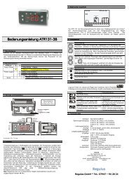
4.1 Panel Assembly<br />
Method of panel assembly and fixing of anchorage hooks.<br />
To dismantle, use a screwdriver and slightly force the fixing hooks to<br />
remove them from the fixing guide.<br />
4.2 Electronics Removal<br />
To remove the electronics, grip the front part using the two specific<br />
side ridges.<br />
WARNING !!<br />
Disconnect the device from<br />
the mains before starting to<br />
configuration or service it.<br />
6
5 Electrical wirings<br />
Although this controller was designed to resist noises in<br />
industrial environments, pease notice following safety<br />
guidelines:<br />
• Separate the feeder line from the power lines.<br />
• Avoid placing near units with remote control switches,<br />
electromagnetic contactors, high powered motors and in all instances<br />
use specific filters.<br />
• Avoid placing near power units, particularly if phase controlled.<br />
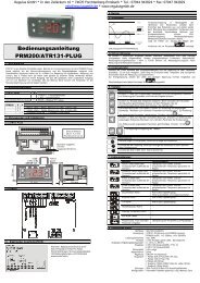
5.1 Wiring diagram<br />
The connections are reported below for the three models available.<br />
5 4 3 2 1<br />
11 12 13 14 15 16<br />
6 7 8 9 10<br />
7
Power<br />
Switching power supply with extended range<br />
24…230 Vac/dc ±15% 50/60Hz - 3VA.<br />
AN1 Analogue Input<br />
For thermocouples K, S, R, J.<br />
• Comply with polarity<br />
• For possible extensions, use a compensated<br />
wire and terminals suitable for the<br />
thermocouples used (compensated)<br />
For thermoresistances PT100, NI100<br />
• For the three-wire connection use wires with<br />
the same section<br />
• For the two-wire connection short-circuit<br />
terminals 1 and 3<br />
• Select internal jumper JP3 as in the figure<br />
3<br />
2<br />
1<br />
For linear signals V/mA<br />
• Comply with polarity<br />
• Select internal jumper JP3 as in the figure<br />
If jumpers are not properly selected,<br />
12Vdc are not available on terminal 3 to<br />
power the sensor.<br />
8
Examples of Connection for linear input<br />
For signals 0….10V<br />
Comply with polarity<br />
For signals 0/4….20mA with three-wire<br />
sensor<br />
OUT : 4...20mA<br />
IN :9...33V DC<br />
P :0...100mbar<br />
Pmax :3bar<br />
T :0..70°C<br />
Comply with polarity<br />
A=Sensor output<br />
B=Sensor ground<br />
C=Sensor power<br />
For signals 0/4….20mA with external power<br />
of sensor<br />
OUT : 4...20mA<br />
IN :9...33V DC<br />
P :0...100mbar<br />
Pmax :3bar<br />
T :0..70°C<br />
Comply with polarity<br />
A=Sensor output<br />
B=Sensor round<br />
For signals 0/4….20mA with two-wire sensor<br />
OUT : 4...20mA<br />
IN :9...33V DC<br />
P :0...100mbar<br />
Pmax :3bar<br />
T :0..70°C<br />
Comply with polarity<br />
A=Sensor output<br />
C=Sensor power supply<br />
Serial input<br />
RS485 Modbus RTU communication<br />
9
Relay Q1 Output<br />
Capacity 5A/250V~ for resistive loads<br />
Relay Q2 output for ATR243-20ABC<br />
Capacity 5A/250V~ for resistive loads<br />
To select Q2 as relay output, remove jumpers<br />
JP5 and JP7 as indicated in the figure (in the<br />
figure is shown default configuration)<br />
Connecting a load without removing the<br />
jumpers will permanently damage the<br />
controller<br />
For models ATR243-21ABC-T and ATR243-<br />
31ABC output Q2 is on terminals 14 and 13.<br />
Relay Q2 output for ATR243-21ABC-T and ATR243-31ABC<br />
Capacity 5A/250V~ for resistive loads<br />
Q3 Relay Output on ATR243-31ABC<br />
Capacity 5A/250V~ resistive loads<br />
10
SSR output<br />
SSR command output 12V/30mA<br />
Insert JP5 and JP7 and select JP9 as in<br />
the figure to use the SSR output.<br />
mA / Volt output<br />
Linear output in mA configurable using<br />
parameters as command (Parameter )<br />
or retransmission of process-setpoint<br />
(Parameter )<br />
Insert JP5 and JP7 and select JP9 as in<br />
figure to use the output in mA.<br />
Linear output in Volt configurable using<br />
parameters as command (Parameter )<br />
or retransmission of process-setpoint<br />
(Parameter )<br />
Insert JP5 and JP7 and select JP9 as in<br />
figure to use the linear output in Volt.<br />
11
Amperometric Transformer Input on ATR243-21ABC-T and<br />
ATR243-31ABC<br />
• Input 50mA for amperometric transformer<br />
• Sampling time 80ms<br />
• Configurable by parameters<br />
Insert JP4 and JP6 as in figure to select<br />
the amperometric transformer input.<br />
Digital Input on ATR243-20ABC<br />
Digital input using parameter .<br />
The use of digital input in this version is possible<br />
only with TC sensors, 0…10V, 0/4…20mA and<br />
0…40mV<br />
Select internal jumper JP3 as in figure.<br />
Digital Input on ATR243-21ABC-T and ATR243-31ABC<br />
Digital input using parameter<br />
Insert JP4 as in figure to select the<br />
digital input.<br />
12
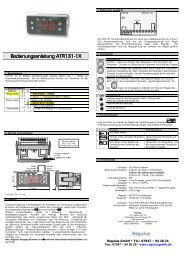
6 Display and Key Functions<br />
1<br />
2<br />
3<br />
7<br />
4<br />
6<br />
8 9 10 5<br />
6.1 Numeric Indicators (Display)<br />
Normally displays the process. During the<br />
1<br />
configuration phase, it displays the parameter<br />
<strong>bei</strong>ng inserted.<br />
2<br />
Normally displays the setpoint. During the<br />
configuration phase, it displays the parameter<br />
value <strong>bei</strong>ng inserted.<br />
6.2 Meaning of Status Lights (Led)<br />
3 C 1<br />
C 2<br />
ON when the output command is on. C1 with<br />
relay/SSR/mA/Volt command or C1 (open) and C2<br />
4 A 1<br />
A 2<br />
A 3<br />
(close) for a motorised valve command.<br />
ON when the corresponding alarm is on.<br />
5 MAN ON when the “Manual” function is on.<br />
6 TUN ON when the controller is running an “Autotune” cycle.<br />
7 REM ON when the controller communicates via serial port.<br />
13
6.3 Keys<br />
8 • Allows to increase the main setpoint.<br />
• During the configuration phase, allows to slide<br />
through parameters. Together with the<br />
modifies them.<br />
key it<br />
• Pressed after the key it allows to increase the<br />
alarm setpoint.<br />
9 • Allows to decrease the main setpoint.<br />
• During the configuration phase, allows to slide<br />
through parameters. Together with the<br />
modifies them.<br />
key it<br />
• Pressed after the key it allows to decrease the<br />
alarm setpoint.<br />
10 • Allows to display the alarm setpoint and runs the<br />
autotuning function.<br />
• Allows to vary the configuration parameters.<br />
7 Controller Functions<br />
7.1 Modifying Main Setpoint and Alarm Setpoint Values<br />
The setpoint value can be changed from the keyboard as follows:<br />
Press Effect Operation<br />
1<br />
Value on display 2<br />
changes<br />
or<br />
2 Visualize alarm<br />
setpoint on display<br />
1<br />
3<br />
Value on display 2<br />
changes<br />
o<br />
Increases or decreases the<br />
main setpoint<br />
Increases or decreases the<br />
alarm set point value<br />
14
7.2 Auto-Tune<br />
The Tuning procedure calculates the controller parameters and can be<br />
manual or automatic according to selection on parameter 57<br />
).<br />
7.3 Manual Tuning<br />
The manual procedure allows the user greater flexibility to decide<br />
when to update PID algorithm work parameters. The procedure can be<br />
activated in two ways.<br />
• By running Tuning from keyboard:<br />
Press the key until display 1 shows the writing with<br />
display 2 showing , press , display 2 shows .<br />
The TUN led switches on and the procedure begins.<br />
• By running Tuning from digital input:<br />
Select on parameter 61 .<br />
On first activation of digital input (commutation on front panel) the<br />
TUN led switches on and on second activation switches off.<br />
7.4 Automatic Tuning<br />
Automatic tuning activates when the controller is switched on or when<br />
the setpoint is modified to a value over 35%.<br />
To avoid an overshoot, the treshold where the controller calculates the<br />
new PID parameters is determined by the setpoint value minus the<br />
“Set Deviation Tune” ( see Parameter 58 ).<br />
To exit Tuning and leave the PID values unchanged, just press the<br />
key until display 1 shows the writing<br />
with the display<br />
showing , press , display 2 shows .<br />
The TUN led switches off and the procedure finishes.<br />
15
7.5 Soft Start<br />
To reach the setpoint the controller can follow a gradient expressed in<br />
units (e.g. degree/hour).<br />
Set the increase value in parameter 62 with the desired<br />
units/hour; only on subsequent activation the controller uses the soft<br />
start function.<br />
Automatic/manual tuning cannot be enabled if the Soft start is active.<br />
7.6 Automatic/Manual Regulation for % Output Control<br />
This function allows you to select automatic functioning or manual<br />
command of the output percentage.<br />
With parameter 60 , you can select two methods.<br />
1. The first selection allows you to enable the<br />
key with the writing<br />
display two shows .<br />
on display 1, while<br />
Press the key to show ; it is<br />
now possible, during the process display, to change the<br />
output percentage using the keys and . To return<br />
to automatic mode, using the same procedure, select<br />
on display 2: the MAN led switches off and<br />
functioning returns to automatic mode.<br />
2. The second selection enables the same<br />
functioning, but with two important variants:<br />
• If there is a temporary lack of voltage or after switch-off, the<br />
manual functioning will be maintained as well as the previously<br />
set output percentage value.<br />
• If the sensor breaks during automatic functioning, the controller<br />
moves to manual mode while maintaining the output percentage<br />
command unchanged as generated by the PID immediately<br />
before breakage.<br />
16
7.7 Pre-Programmed Cycle<br />
The pre-programmed cycle function activates by setting or<br />
in parameter 59 .<br />
First option : the controller reaches setpoint1 basing on the<br />
gradient set in parameter 62 , then it reaches maximum power<br />
up to setpoint2. When the process reaches maximum power, this<br />
setpoint is maintained for the time set in parameter 63 . On<br />
expiry, the command output is disabled and the controller displays<br />
.<br />
Setpoint<br />
Max.<br />
power<br />
Setpoint 2<br />
Hold<br />
Natural<br />
cooling<br />
Setpoint 1<br />
Gradient<br />
Time<br />
The cycle starts at each activation of the controller, or via digital input if<br />
it is enabled for this type of functioning (see parameter 61 ).<br />
Second option : start-up is decided only on activation of the<br />
digital input, according to the setting of parameter 61 . On<br />
start-up, the controller reaches setpoint 1 basing on the gradient set in<br />
parameter 62 . When the process reaches this gradient, it is<br />
maintained for the time set in parameter 63 . On expiry, the<br />
command output is disabled and the controller displays .<br />
Setpoint<br />
Gradient<br />
Setpoint 1<br />
Hold<br />
Natural<br />
cooling<br />
Time<br />
17
7.8 Memory Card (optional)<br />
Parameters and setpoint values can be duplicated from one controller<br />
to another using the Memory card.<br />
There are two methods:<br />
• With the controller connected to the power supply<br />
Insert the memory card when the controller is off.<br />
On activation display 1 shows and display 2 shows<br />
(Only if the correct values are saved in the memory card). By<br />
pressing the key display 2 shows , then confirm using the<br />
key. The controller loads the new data and starts again.<br />
RED LIGHT: waiting for programming<br />
GREEN LIGHT: done<br />
LED ROSSO: acceso in programmazione<br />
LED VERDE: programmazione eseguita<br />
• With the controller not connected to power supply.<br />
The memory card is equipped with an internal battery with an<br />
autonomy of about 1000 uses.<br />
Insert the memory card and press the programming buttons.<br />
When writing the parameters, the led turns red and on completing the<br />
procedure it changes to green. It is possible to repeat the procedure<br />
without any particular attention.<br />
18
Updating Memory Card<br />
To update the memory card values, follow the procedure described in<br />
the first method, setting display 2 to so as not to load the<br />
parameters on controller 2 .<br />
Enter configuration and change at least one parameter.<br />
Exit configuration. Changes are saved automatically.<br />
8 LATCH ON Functions<br />
For use with input (potentiometer 6K) and<br />
(potentiometer 150K ) and with linear input (0…10V, 0...40mV,<br />
0/4…20mA), you can associate start value of the scale (parameter 6<br />
) to the minimum position of the sensor and value of the scale<br />
end (parameter 7<br />
) to the maximum position of the sensor<br />
(parameter 8 configured as ).<br />
It is also possible to fix the point in which the controller will display 0<br />
(however keeping the scale range between and )<br />
using the “virtual zero” option by setting or in<br />
parameter 8 . If you set the virtual zero will reset after<br />
each activation of the tool; if you set the virtual zero remains<br />
fixed once tuned.<br />
To use the LATCH ON function configure as you wish the parameter<br />
. 3<br />
2 If on activation the controller does not display it means no data have been<br />
saved on the memory card, but it is possible to update values.<br />
3 The tuning procedure starts by exiting the configuration after changing the parameter.<br />
19
For the calibration procedure refer to the following table:<br />
Press Effect Operation<br />
1 Exit parameters<br />
configuration. Display 2<br />
Position the sensor on the<br />
minimum functioning value<br />
shows the writing .<br />
2 Set the value to minimum.<br />
The display shows<br />
3 Set the value to maximum.<br />
The display shows<br />
4 Set the virtual zero value.<br />
The display shows<br />
N.B.: for selection of<br />
the procedure in<br />
point 4 should be followed<br />
on each re-activation.<br />
(associated with )<br />
Position the sensor on the<br />
maximum functioning<br />
position (associated with<br />
)<br />
To exit the standard<br />
procedure press .<br />
For “virtual zero” settings<br />
position the sensor on the<br />
zero point.<br />
To exit the procedure press<br />
.<br />
MAX<br />
MIN<br />
ZERO<br />
20
8.1 Loop Break Alarm On Amperometric Transformer<br />
This function allows to measure load current and to manage an alarm<br />
during malfunctioning with power in short circuit or always off. The<br />
amperometric transformer connected to terminals 15 and 16 must be<br />
50mA (sampling time 80ms).<br />
• Set scale end value of the amperometric transformer in Amperes<br />
on parameter 47<br />
• Set the intervention threshold of the Loop break alarm in Amperes<br />
on parameter 48<br />
• Set the intervention delay time of the Loop break alarm on<br />
parameter 49<br />
• You can associate the alarm with a relay by setting the parameter<br />
, or as .<br />
If a remote control switch or SSR remains closed, the controller signals<br />
the fault by showing on display 2 (alternatively with a<br />
command setpoint).<br />
If instead the power stage remains open, or the load current is lower<br />
than the value set on , the controller shows on<br />
display.<br />
You can display the current absorbed during the closure phase of the<br />
power stage.<br />
Press Effect Operation<br />
1 This key enables to scroll<br />
on display 2 the output Press until the writing<br />
percentage, auto/man<br />
appears on<br />
selection, setpoint and<br />
display 1 and display 2<br />
alarms.<br />
shows the current in<br />
amperes ( >0).<br />
The value is also<br />
maintained when no<br />
current circulates on the<br />
load.<br />
21
8.2 Digital Input Functions<br />
Digital input is programmable for several functions which are useful to<br />
simplify controller operability. Select the desired function on parameter<br />
62 .<br />
1. Hold function (enabled by setting or ) allows to<br />
lock the reading of sensors when the digital input is active<br />
(useful for wide ranging oscillation on less significant values).<br />
During the lock phase, display 2 flashes and shows .<br />
2. Enables/disables the autotuning function from digital input if the<br />
parameter is set on .<br />
3. Enable regulation with or .<br />
4. Switch from automatic to manual functioning if is set<br />
on or .<br />
5. Start of pre-programmed cycle (see paragraph 7.7) with<br />
.<br />
6. Change setpoint function.<br />
This function is useful where there are 2 to 4 working thresholds<br />
required during system functioning without having to press the<br />
arrow keys.<br />
To enable the function use the parameter , by<br />
selecting the number of setpoints desired (no. thresholds<br />
switch). They can be switched during functioning by pressing<br />
the<br />
key.<br />
N.B.:<br />
The digital input functions are not available with sensors PT100 and<br />
NI100 on model ATR243-20ABC.<br />
22
8.3 Dual Action Heating-Cooling<br />
ATR243 is also suitable also for systems requiring a combined heatingcooling<br />
action.<br />
The command output must be configured as Heating PID<br />
( = and with a greater than 0), and one of the<br />
alarms ( , or ) must be configured as .<br />
The command output must be connected to the actuator responsible<br />
for heat, while the alarm will control cooling action.<br />
The parameters to configure for the Heating PID are:<br />
= Command output type (Heating)<br />
: Heating proportional band<br />
: Integral time of heating and cooling<br />
: Derivative time of heating and cooling<br />
: Heating time cycle<br />
The parameters to configure for the Cooling PID are the following<br />
(example: action associated to alarm1):<br />
= Alarm1 selection (cooling)<br />
: Proportional band multiplier<br />
: Overlapping/Dead band<br />
: Cooling time cycle<br />
The parameter (that ranges from 1.00 to 5.00) determines the<br />
proportional band of cooling basing on the formula:<br />
Cooling proportional band = *<br />
This gives a proportional band for cooling which will be the same as<br />
heating band if = 1.00, or 5 times greater if = 5.00.<br />
The integral time and derivative time are the same for both actions.<br />
The parameter determines the percentage overlapping<br />
between the two actions. For systems in which the heating output and<br />
cooling output must never be simultaneously active a dead band<br />
( ≤ 0) must be configured, and vice versa you can configure an<br />
overlapping ( > 0).<br />
23
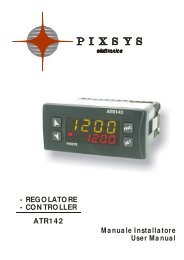
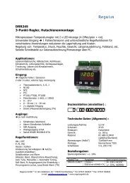
The following figure shows an example of dual action PID (heatingcooling)<br />
with = 0 and = 0.<br />
24
The parameter<br />
cycle .<br />
The parameter<br />
has the same meaning as the heating time<br />
(cooling fluid) pre-selects the proportional<br />
band multiplier and the cooling PID time cycle basing<br />
on the type of cooling fluid:<br />
Cooling fluid type<br />
Air 1.00 10<br />
Oil 1.25 4<br />
Water 2.50 2<br />
Once selected, the parameter , the parameters ,<br />
and<br />
can however be changed.<br />
9 Serial Communication<br />
ATR243-21ABC-T, equipped with RS485, can receive and broadcast<br />
data via serial communication using MODBUS RTU protocol. The<br />
device can only be configured as a Slave. This function enables the<br />
control of multiple controllers connected to a supervisory system<br />
(SCADA).<br />
Each controller responds to a master query only if the query contains<br />
the same address as that in the parameter . The addresses<br />
permitted range from 1 to 254 and there must not be controllers with<br />
the same address on the same line.<br />
Address 255 can be used by the master to communicate with all the<br />
connected equipment (broadcast mode), while with 0 all the devices<br />
receive the command, but no response is expected.<br />
ATR243 can introduce a delay (in milliseconds) in the response to the<br />
master request. This delay must be set on parameter 72<br />
Each parameter change is saved by the controller in the EEPROM<br />
memory (100000 writing cycles), while the setpoints are saved with a<br />
delay of ten seconds after the last change.<br />
NB: Changes made to words that are different from those reported in<br />
the following table can lead to malfunction.<br />
25
Modbus RTU protocol features<br />
Baud-rate Can be selected on parameter 70<br />
4800bit/sec<br />
9600bit/sec<br />
19200bit/sec<br />
28800bit/sec<br />
38400bit/sec<br />
57600bit/sec<br />
Format 8, N, 1 (8bit, no parity, 1 stop)<br />
Supported<br />
functions<br />
WORD READING (max 20 word) (0x03, 0x04)<br />
SINGLE WORD WRITING (0x06)<br />
MULTIPLE WORDS WRITING (max 20 word)<br />
(0x10)<br />
The list below includes all the available addresses, where:<br />
RO = Read Only<br />
R/W = Read/Write<br />
WO = Write Only<br />
Modbus<br />
address<br />
Description<br />
Read<br />
Write<br />
Reset<br />
value<br />
0 Device type RO EEPROM<br />
1 Software version RO EEPROM<br />
5 Slave Address R/W EEPROM<br />
6 Boot version RO EEPROM<br />
50 Automatic addressing WO -<br />
51 System code comparison WO -<br />
1000 Process (with tenths of degree for temperature RO ?<br />
sensors; digits for linear sensors)<br />
1001 Setpoint1 R/W EEPROM<br />
1002 Setpoint2 R/W EEPROM<br />
1003 Setpoint3 R/W EEPROM<br />
1004 Setpoint4 R/W EEPROM<br />
1005 Alarm1 R/W EEPROM<br />
1006 Alarm2 R/W EEPROM<br />
1007 Alarm3 R/W EEPROM<br />
1008 Setpoint gradient RO EEPROM<br />
26
1009 Relay status (0=off, 1=on)<br />
RO 0<br />
Bit 0 = Q1 relay<br />
Bit 1 = Q2 relay<br />
Bit 2 = reserved<br />
Bit 3 = SSR<br />
1010 Heating output percentage<br />
RO 0<br />
(0-10000)<br />
1011 Cooling output percentage<br />
RO 0<br />
(0-10000)<br />
1012 Alarms status (0=none, 1=active)<br />
RO 0<br />
Bit0 = Alarm 1<br />
Bit1 = Alarm 2<br />
1013 Manual reset: write 0 to reset all the alarms. WO 0<br />
In reading (0=not resettable, 1=resettable):<br />
Bit0 = Alarm 1<br />
Bit1 = Alarm 2<br />
1014 Error flags<br />
RO 0<br />
Bit0 = Eeprom writing error<br />
Bit1 = Eeprom reading error<br />
Bit2 = Cold junction error<br />
Bit3 = Process error (sensor)<br />
Bit4 = Generic error<br />
Bit5 = Hardware error<br />
Bit6 = L.B.A.O. error<br />
Bit7 = L.B.A.C. error<br />
1015 Cold junction temperature (tenths of degree) RO ?<br />
1016 Start/Stop<br />
R/W 0<br />
0=controller in STOP<br />
1=controller in START<br />
1017 Lock conversion ON/OFF<br />
0=Lock conversion off<br />
R/W 0<br />
1=Lock conversion on<br />
1018 Tuning ON/OFF<br />
R/W 0<br />
0=Tuning off<br />
1=Tuning on<br />
1019 Automatic/manual selection<br />
R/W 0<br />
0=automatic<br />
1=manual<br />
1020 TA Current ON (amperes to tenths) RO ?<br />
1021 TA Current OFF (ampere to tenths) RO ?<br />
1022 OFF LINE 1 time (milliseconds) R/W 0<br />
1023 Instant Current (Ampere) RO 0<br />
1 If value is 0, the control is disabled. If different from 0, it is the max. time which can<br />
elapse between two pollings before the controller goes off-line.<br />
If it goes off-line, the controller returns to Stop mode, the control output is disabled<br />
but the alarms are active.<br />
27
2001 Parameter 1 R/W EEPROM<br />
2002 Parameter 2 R/W EEPROM<br />
... ... ... ...<br />
2072 Parameter 72 R/W EEPROM<br />
3000 Disabling serial control of machine 2 WO 0<br />
3001 First word display1 (ASCII) R/W 0<br />
3002 Second word display1 (ASCII) R/W 0<br />
3003 Third word display1 (ASCII) R/W 0<br />
3004 Fourth word display1 (ASCII) R/W 0<br />
3005 Fifth word display1 (ASCII) R/W 0<br />
3006 Sixth word display1 (ASCII) R/W 0<br />
3007 Seventh word display1 (ASCII) R/W 0<br />
3008 Eighth word display1 (ASCII) R/W 0<br />
3009 First word display2 (ASCII) R/W 0<br />
3010 Second word display2 (ASCII) R/W 0<br />
3011 Third word display2 (ASCII) R/W 0<br />
3012 Fourth word display2 (ASCII) R/W 0<br />
3013 Fifth word display2 (ASCII) R/W 0<br />
3014 Sixth word display2 (ASCII) R/W 0<br />
3015 Seventh display2 (ASCII) R/W 0<br />
3016 Eighth word display2 (ASCII) R/W 0<br />
3017 Word LED<br />
R/W 0<br />
Bit 0 = LED C1<br />
Bit 1 = LED C2<br />
Bit 2 = LED A1<br />
Bit 3 = LED A2<br />
Bit 4 = LED A3<br />
Bit 5 = LED MAN<br />
Bit 6 = LED TUN<br />
Bit 7 = LED REM<br />
3018 Word keys<br />
(write 1 to command keys)<br />
R/W 0<br />
Bit 0 =<br />
Bit 1 =<br />
Bit 2 =<br />
3019 Word serial relay<br />
R/W 0<br />
Bit 0 = Q1 relay<br />
Bit 1 = Q2 relay<br />
3020 Word SSR serial (0=off, 1=on) R/W 0<br />
3021 Word output 0...10V serial (0…10000) R/W 0<br />
2 By writing 1 on this word, the effects of the writing are cancelled on all the Modbus<br />
addresses from 3001 to 3022. Control therefore returns to the controller.<br />
28
3022 Word output 4...20mA serial (0…10000) R/W 0<br />
10 Configuration<br />
10.1 Modify Configuration Parameter<br />
For configuration parameters see paragraph 11.<br />
1<br />
2<br />
3<br />
4<br />
5<br />
6<br />
Press Effect Operation<br />
for 3<br />
seconds.<br />
or<br />
to confirm<br />
or<br />
or<br />
+<br />
+<br />
Simultaneou<br />
sly<br />
Display 1 shows<br />
with the 1st<br />
digit flashing, while<br />
display 2 shows<br />
.<br />
Change the flashing digit<br />
and move to the next<br />
one using the<br />
key.<br />
Display 1 shows the first<br />
parameter and display 2<br />
shows the value.<br />
Slide up/down through<br />
parameters<br />
Increase or decrease the<br />
value displayed by<br />
pressing firstly and<br />
then an arrow key.<br />
End of configuration<br />
parameter change.<br />
The controller exits from<br />
programming.<br />
Enter password<br />
Enter the new data which<br />
will be saved on<br />
releasing the keys.<br />
To change another<br />
parameter return to point<br />
4.<br />
29
11 Table of Configuration Parameters<br />
The following table includes all parameters. Some of them will not be<br />
visible on the models which are not provided with relevant hardware<br />
features.<br />
no. Display Parameter description Entering range<br />
1<br />
Command<br />
Output<br />
Select command output<br />
type<br />
Default<br />
(necessary to use retransmission<br />
function)<br />
ATR243-20ABC<br />
COMMAND ALARM 1<br />
Q1<br />
Q2<br />
Q2<br />
SSR<br />
Q1(opens)<br />
Q2(closes)<br />
4...20mA<br />
0...20mA<br />
0...10V<br />
ATR243-21ABC-T<br />
COMMAND ALARM 1 ALARM 2<br />
Q1 Q2 SSR<br />
Q1<br />
Q1<br />
-<br />
Q1<br />
Q1<br />
Q1<br />
Q2 Q1 SSR<br />
SSR Q1 Q2<br />
Q1(opens)<br />
SSR -<br />
Q2(closes)<br />
4...20mA Q1 Q2<br />
0...20mA Q1 Q2<br />
0...10V Q1 Q2<br />
30
ATR243-31ABC<br />
COMMAND ALARM 1 ALARM 2 ALARM 3<br />
Q1 Q2 Q3 SSR<br />
Q2 Q1 Q3 SSR<br />
SSR Q1 Q2 Q3<br />
Q2(opens) Q1 SSR -<br />
Q3(closes)<br />
4...20mA Q1 Q2 Q3<br />
0...20mA Q1 Q2 Q3<br />
0...10V Q1 Q2 Q3<br />
2<br />
Sensor<br />
Analog input<br />
configuration<br />
Tc-K -260…1360°C<br />
(Default setting)<br />
Tc-S -40…1760°C<br />
Tc-R -40…1760°C<br />
Tc-J -200…1200°C<br />
PT100 -100…600°C<br />
PT100 -100…140°C<br />
NI100 -60…180°C<br />
NTC10K -40…125°C<br />
PTC1K -50…150°C<br />
PT500 -100…600°C<br />
PT1000 -100…600°C<br />
0…10Volt<br />
0…20mA<br />
4…20mA<br />
0…40mVolt<br />
Potentiometer<br />
max 6Kohm<br />
Only ATR243-21/31ABC<br />
Select number of<br />
displayed decimal points<br />
Potentiometer<br />
max 150Kohm<br />
50mA secondary<br />
amperometric transformer<br />
Default<br />
31
3 Decimal Point<br />
4<br />
5<br />
6<br />
7<br />
8<br />
Lower Limit<br />
Setpoint<br />
Upper Limit<br />
Setpoint<br />
Lower Linear<br />
Input<br />
Upper Linear<br />
Input<br />
Latch On<br />
Function<br />
Lower limit setpoint<br />
Upper limit setpoint<br />
Lower range limit An1<br />
only for linear input<br />
Upper range limit An1<br />
only for linear input<br />
Automatic setting of limits<br />
for Linear input<br />
-999…+9999 digit ∗<br />
(degrees if temperature)<br />
Default: 0.<br />
-999…+9999 digit*<br />
(degrees if temperature)<br />
Default: 1750.<br />
-999…+9999 digit*<br />
Default: 0.<br />
-999…+9999 digit*<br />
Default: 1000.<br />
(Disabled) Default<br />
(Standard)<br />
(Virtual Zero Stored)<br />
9<br />
10<br />
11<br />
Offset<br />
Calibration<br />
Gain<br />
Calibration<br />
Action type<br />
Offset calibration<br />
Number added to<br />
displayed value of<br />
process (normally<br />
corrects the room<br />
temperature value)<br />
Gain calibration<br />
Value multiplied with<br />
process value to perform<br />
calibration on working<br />
point<br />
Regulation type<br />
(Virtual Zero Initialized)<br />
-999…+1000 digit* for linear sensors<br />
and potentiometers.<br />
-200.0…+100.0 tenths for<br />
temperature sensors.<br />
Default: 0.0.<br />
-10.0%…+10.0%<br />
Default: 0.0.<br />
: Heating (N.O.) Default<br />
: Cooling (N.C.)<br />
12<br />
Command<br />
Reset<br />
Type of reset for state of<br />
command contact<br />
(always automatic in PID<br />
functioning)<br />
: HEat Off Over Setpoint<br />
(Automatic Reset) Default<br />
(Manual Reset)<br />
(Manual Reset Stored)<br />
∗ The display of the decimal point depends on the setting of parameter<br />
and the parameter .<br />
32
13<br />
14<br />
15<br />
16<br />
17<br />
18<br />
19<br />
20<br />
21<br />
22<br />
Command<br />
State Error<br />
Command<br />
Led<br />
Command<br />
Hysteresis<br />
Command<br />
Delay<br />
Command<br />
Setpoint<br />
Protection<br />
Proportional<br />
Band<br />
Integral Time<br />
Derivative<br />
Time<br />
Cycle Time<br />
Output Power<br />
Limit<br />
State of contact for<br />
command output in case<br />
of error<br />
State of the OUT1 led<br />
corresponding to the<br />
relevant contact<br />
Hysteresis in ON/OFF or<br />
dead band in P.I.D.<br />
Command delay (only in<br />
ON/OFF functioning).<br />
(In case of servo valve it<br />
also functions in PID and<br />
represents the delay<br />
between the opening and<br />
closure of the two<br />
contacts)<br />
Allows or not to change<br />
the command setpoint<br />
value<br />
Proportional band<br />
Process inertia in units<br />
(E.g.: if temperature is in<br />
°C)<br />
Integral time. Process<br />
inertia in seconds<br />
Derivative time. Normally<br />
¼ the integral time<br />
Cycle time (for PID on<br />
remote control switch<br />
10/15sec, for PID on<br />
SSR 1 sec) or servo<br />
time (value declared by<br />
servo-motor<br />
manufacturer)<br />
Limit of output power % 10-100 %<br />
Default: 100.<br />
Default<br />
Default<br />
-999…+999 digits ∗<br />
(tenths of degree if temperature)<br />
Default: 0.0.<br />
-180…+180 seconds (tenths of<br />
second in case of servo valve).<br />
Negative: delay in switching off<br />
phase.<br />
Positive: delay in activation phase.<br />
Default: 0.<br />
Default<br />
0 on/off if<br />
equal to 0. Default<br />
1-9999 digit* (degrees if<br />
temperature)<br />
0.0-999.9 seconds (0 integral<br />
disabled)<br />
Default: 0.<br />
0.0-999.9 seconds (0 derivative<br />
disabled)<br />
Default: 0.<br />
1-300 seconds<br />
Default: 10.<br />
∗ The display of the decimal point depends on the setting of parameter<br />
and parameter .<br />
33
23<br />
Alarm 1<br />
Alarm 1 selection.<br />
Intervention of the alarm<br />
is associated with AL1<br />
(Disabled) Default<br />
(Absolute Alarm)<br />
(Band Alarm)<br />
(High Deviation Alarm)<br />
(Low Deviation Alarm)<br />
(Absolute Command setpoint Alarm)<br />
(Start Alarm) Active in Run<br />
24<br />
Alarm 1 State<br />
Output<br />
Only ATR243-21/31ABC<br />
Alarm 1 output contact<br />
and intervention type<br />
(Cooling)<br />
(Loop Break Alarm)<br />
(n.o. start) Default<br />
Normally open, active at start<br />
(n.c. start)<br />
Normally closed, active at start<br />
(n.o. threshold)<br />
Normally open, active on reaching<br />
alarm 4<br />
25<br />
Alarm 1<br />
Reset<br />
Type of Reset for contact<br />
of alarm 1<br />
(n.c. threshold)<br />
Normally closed on reaching alarm 4<br />
(Automatic Reset) Default<br />
(Manual Reset)<br />
26<br />
27<br />
28<br />
Alarm 1 State<br />
Error<br />
Alarm 1 Led<br />
Alarm 1<br />
Hysteresis)<br />
State of contact for alarm<br />
1 output in case of error<br />
State of the OUT2 led<br />
corresponding to the<br />
relative contact<br />
Alarm 1 hysteresis<br />
(Manual Reset Stored)<br />
Default<br />
Default<br />
-999…+999 digit ∗<br />
(tenths of degree if temperature).<br />
Default: 0.<br />
4 On activation, the output is inhibited if the controller is in alarm mode. Activates only<br />
if alarm condition reappers, after that it was restored.<br />
34
29<br />
30<br />
31<br />
Alarm 1 Delay<br />
Alarm 1<br />
Setpoint<br />
Protection<br />
Alarm 2<br />
Alarm 1 delay<br />
Alarm 1 set protection.<br />
Does not allow user to<br />
modify setpoint<br />
Alarm 2 selection.<br />
Alarm intervention is<br />
associated with AL2<br />
-180…+180 Seconds<br />
Negative: delay in alarm output<br />
phase.<br />
Positive: delay in alarm entry phase.<br />
Default: 0.<br />
Default<br />
(Disabled) Default<br />
(Absolute Alarm)<br />
(Band Alarm)<br />
(High Deviation Alarm)<br />
(Low Deviation Alarm)<br />
(Absolute Command setpoint Alarm)<br />
(Start Alarm)<br />
(Cooling)<br />
32<br />
Alarm 2 State<br />
Output<br />
Alarm 2 output contact<br />
and intervention type<br />
(Loop Break Alarm)<br />
(n.o. start) Default<br />
Normally open, active at start<br />
(n.c. start)<br />
Normally closed, active at start<br />
(n.o. threshold)<br />
Normally open, active on reaching<br />
alarm 5<br />
(n.c. threshold)<br />
Normally closed, active on reaching<br />
alarm 5<br />
∗ The display of the decimal point depends on the setting of parameter<br />
and parameter .<br />
5 On activation, the output is inhibited if the controller is in alarm mode. It activates<br />
only if alarm condition reappears after that it was restored.<br />
35
33<br />
Alarm 2<br />
Reset<br />
Type of Reset for contact<br />
of alarm 2<br />
(Automatic Reset)<br />
Default<br />
(Manual Reset)<br />
34<br />
35<br />
36<br />
37<br />
38<br />
39<br />
Alarm 2 State<br />
Error<br />
Alarm 2 Led<br />
Alarm 2<br />
Hysteresis<br />
Alarm 2 Delay<br />
Alarm 2<br />
Setpoint<br />
Protection<br />
Alarm 3<br />
State of contact for alarm<br />
2 output in case of error<br />
State of OUT2 led<br />
corresponding to relative<br />
contact<br />
Alarm 2 hysteresis<br />
Alarm 2 delay<br />
Alarm 2 set protection.<br />
Does not allow operator<br />
to change value of<br />
setpoint<br />
Alarm 3 selection.<br />
Alarm intervention is<br />
associated with AL3<br />
(Manual Reset Stored)<br />
Default<br />
Default<br />
-999…+999 digit ∗<br />
(tenths of degree if temperature).<br />
Default: 0.<br />
-180…+180 Seconds<br />
Negative: delay in alarm output<br />
phase.<br />
Positive: delay in alarm entry phase.<br />
Default: 0.<br />
Default<br />
(Disabled) Default<br />
(Absolute Alarm)<br />
(Band Alarm)<br />
(High Deviation Alarm)<br />
(Low Deviation Alarm)<br />
(Absolute Command setpoint Alarm)<br />
(Start Alarm)<br />
(Cooling)<br />
(Loop Break Alarm)<br />
∗ The display of the decimal point depends on the setting of parameter<br />
and parameter .<br />
36
40<br />
Alarm 3 State<br />
Output<br />
Alarm 3 output contact<br />
and intervention type<br />
(n.o. start) Default<br />
Normally open, active at start<br />
(n.c. start)<br />
Normally closed, active at start<br />
(n.o. threshold)<br />
Normally open, active on reaching<br />
alarm 6<br />
41<br />
Alarm 3<br />
Reset<br />
Type of Reset for contact<br />
of alarm 3<br />
(n.c. threshold)<br />
Normally closed, active on reaching<br />
alarm 6<br />
(Automatic Reset) Default<br />
(Manual Reset)<br />
42<br />
43<br />
44<br />
45<br />
46<br />
47<br />
Alarm 3 State<br />
Error<br />
Alarm 3 Led<br />
Alarm 3<br />
Hysteresis<br />
Alarm 3 Delay<br />
Alarm 3<br />
Setpoint<br />
Protection<br />
Amperometric<br />
Transformer<br />
State of contact for alarm<br />
3 output in case of error<br />
Defines the state of<br />
OUT3 led corresponding<br />
to the relative contact<br />
Alarm 3 hysteresis<br />
Alarm 3 delay<br />
Alarm 3 set protection.<br />
Does not allow the<br />
operator to change the<br />
value of setpoint<br />
Activation and scale of<br />
amperometric<br />
transformer<br />
(Manual Reset Stored)<br />
Default<br />
Default<br />
-999…+999 digit ∗<br />
(tenths of degree if temperature).<br />
Default: 0.<br />
-180…+180 Seconds<br />
Negative: delay in alarm output<br />
phase.<br />
Positive: delay in alarm entry phase.<br />
Default: 0.<br />
Default<br />
0 Disabled<br />
1-200 Ampere<br />
Default: 0.<br />
6 On activation, the output is inhibited if the controller is in alarm mode. It activates<br />
only if alarm condition reappears after that it was restored.<br />
∗ The display of the decimal point depends on the setting of parameter<br />
and parameter .<br />
37
48<br />
49<br />
50<br />
Loop Break<br />
Alarm<br />
Threshold<br />
(Loop Break<br />
Alarm Delay)<br />
Cooling Fluid<br />
Intervention threshold of<br />
Loop break alarm<br />
Delay time for Loop<br />
break alarm intervention<br />
Type of cooling fluid<br />
0.0-200.0 Ampere<br />
Default: 50.0.<br />
00.00-60.00 mm.ss<br />
Default: 01.00.<br />
Default<br />
51<br />
52<br />
53<br />
54<br />
38<br />
Proportional<br />
Band<br />
Multiplier<br />
(Overlap/Dea<br />
d Band)<br />
Cooling Cycle<br />
Time<br />
Conversion<br />
Filter<br />
Proportional band<br />
multiplier<br />
1.00-5.00<br />
Default: 1.00.<br />
Overlapping/Dead band -20.0-50.0%<br />
Default: 0.<br />
Cycle time for cooling<br />
output<br />
ADC filter: number of<br />
means on analog-digital<br />
conversions<br />
1-300 seconds<br />
Default: 10.<br />
Default<br />
(Disabled)<br />
(2 Samples Mean)<br />
(3 Samples Mean)<br />
(4 Samples Mean)<br />
(5 Samples Mean)<br />
(6 Samples Mean)<br />
(7 Samples Mean)<br />
(8 Samples Mean)<br />
(9 Samples Mean)<br />
(10 Samples Mean)<br />
(11 Samples Mean)<br />
(12 Samples Mean)<br />
(13 Samples Mean)<br />
(14 Samples Mean)<br />
(15 Samples Mean)
55<br />
Conversion<br />
Frequency<br />
Frequency of sampling of<br />
analog-digital converter<br />
(242 Hz)<br />
(123 Hz)<br />
(62 Hz)<br />
(50 Hz)<br />
(39 Hz)<br />
(33.2 Hz)<br />
(19.6 Hz)<br />
(16.7 Hz) Default<br />
(12.5 Hz)<br />
(10 Hz)<br />
(8.33 Hz)<br />
(6.25 Hz)<br />
56<br />
Visualisation<br />
Filter<br />
Visualisation filter<br />
(4.17 Hz)<br />
(Disabled) Default<br />
(First Order)<br />
(2 Samples Mean)<br />
(3 Samples Mean)<br />
(4 Samples Mean)<br />
(5 Samples Mean)<br />
(6 Samples Mean)<br />
(7 Samples Mean)<br />
(8 Samples Mean)<br />
(9 Samples Mean)<br />
(10 Samples Mean)<br />
(no filter without damping)<br />
57<br />
Tune<br />
Tuning type selection<br />
damping)<br />
(First Order without<br />
(Disabled) Default<br />
(Automatic)<br />
PID parameters are calculated at<br />
activation and change of set.<br />
(Manual)<br />
39
58<br />
59<br />
Setpoint<br />
Deviation<br />
Tune<br />
Operating<br />
Mode<br />
Select the deviation from<br />
the command setpoint,<br />
for the threshold used by<br />
autotuning to calculate<br />
the PID parameters<br />
Select operating mode<br />
Launch from keys or digital input.<br />
0-5000 digit ∗ (tenths of degree if<br />
temperature).<br />
Default: 10.<br />
(Controller) Default<br />
(Programmed Cycle)<br />
(2 Thresholds Switch)<br />
(2 Thresholds Switch<br />
Impulsive)<br />
(3 Thresholds Switch<br />
Impulsive)<br />
(4 Thresholds Switch<br />
Impulsive)<br />
(Time Reset)<br />
60<br />
Automatic /<br />
Manual<br />
Enable automatic/manual<br />
selection<br />
(Programmed Cycle<br />
Start/Stop)<br />
(Disabled) Default<br />
(Enabled)<br />
61<br />
Digital Input<br />
Digital input functioning<br />
(P59 selection must be<br />
or )<br />
(Enabled Stored)<br />
(Disabled) Default: 0.<br />
(Start/Stop)<br />
(Run n.o.)<br />
(Run n.c.)<br />
(Lock Conversion n.o.)<br />
(Lock Conversion n.c.)<br />
(Tune) Manual<br />
impulse)<br />
(Automatic Manual<br />
(Automatic Manual<br />
∗ The display of the decimal point depends on the setting of the parameter<br />
and the parameter .<br />
40
62<br />
63<br />
64<br />
65<br />
Gradient<br />
Maintenance<br />
Time<br />
User Menu<br />
Cycle<br />
Programmed<br />
Visualization<br />
Type<br />
Increase gradient for soft<br />
start or pre-programmed<br />
cycle<br />
Maintenance time for<br />
pre-programmed cycle<br />
Allows the rise gradient<br />
and the maintenance<br />
time to be changed from<br />
the user menu, in preprogrammed<br />
cycle<br />
functioning<br />
Select visualization for<br />
display 1 and 2<br />
Contact)<br />
0 disabled<br />
1-9999 Digit/time ∗<br />
(degrees/hours with display of tenths<br />
if temperature)<br />
Default: 0.<br />
00.00-24.00 hh.mm<br />
Default: 00.00.<br />
(Disabled) Default<br />
(Gradient)<br />
(Maintenance Time)<br />
(All)<br />
(1 Process, 2 Setpoint) Default<br />
(1 Process, 2 Hide after 3 sec.)<br />
(1 Setpoint, 2 Process)<br />
(1 Setpoint, 2 Hide after 3 sec.)<br />
66<br />
Degree<br />
Select degree type<br />
Default<br />
(1 Process, 2 Ampere.)<br />
: Centigrade<br />
67<br />
Retransmissi<br />
on<br />
Retransmission for<br />
output 0-10V or<br />
4…20mA.<br />
(Select Jumper JP5,<br />
JP7 and JP9).<br />
Parameters 68 and 69<br />
define the lower and<br />
upper limits of the scale.<br />
:Fahrenheit<br />
(Disabled) Default<br />
(Volt Process)<br />
(mA Process)<br />
(Volt Command setpoint)<br />
(mA Command setpoint)<br />
N.B. It's suggested to<br />
supply device at 24Vdc<br />
to warrant an higher<br />
stability for<br />
(Volt Output Percentage)<br />
(mA Output Percentage)<br />
∗ The display of the decimal point depends on the setting of parameter<br />
and parameter .<br />
41
etransmission output<br />
(Volt Alarm 1 setpoint)<br />
(mA Alarm 1 setpoint)<br />
(Volt Alarm 2 setpoint)<br />
(mA Alarm 2 setpoint)<br />
(Volt A.T.)<br />
(mA A.T.)<br />
68<br />
69<br />
70<br />
Lower Limit<br />
Retransmissi<br />
on<br />
Upper Limit<br />
Retransmissi<br />
on<br />
Baud Rate<br />
Lower limit range of<br />
linear output<br />
Upper limit range of<br />
linear output<br />
Select baud rate for<br />
serial communication<br />
-999…+9999 digit ∗ (degrees if<br />
temperature)<br />
Default: 0.<br />
-999…+9999 digit* (degrees if<br />
temperature)<br />
Default: 1000.<br />
Default<br />
71<br />
72<br />
Slave<br />
Address<br />
Serial Delay<br />
Select slave address for<br />
serial communication<br />
Select serial delay<br />
1 – 254<br />
Default: 254.<br />
0 – 100 milliseconds<br />
Default: 20.<br />
∗ The display of the decimal point depends on the setting of parameter<br />
parameter .<br />
42<br />
and
12 Alarm Intervention Modes<br />
Absolute Alarm or Threshold Alarm ( selection)<br />
Pv<br />
Alarm Spv<br />
Hysteresis<br />
parameter<br />
> 0<br />
Absolute alarm with controller<br />
in heating functioning<br />
(Par.11 selected )<br />
and hysteresis value greater<br />
than “0” (Par.28 > 0).<br />
Off<br />
On<br />
Off<br />
On<br />
Time<br />
Alarm<br />
output<br />
N.B.: The example refers to alarm 1;<br />
the function can also be enabled for<br />
alarms 2 and 3 on models that<br />
include it.<br />
Pv<br />
Hysteresis<br />
parameter<br />
< 0<br />
Alarm Spv<br />
Absolute alarm with controller<br />
in heating functioning<br />
(Par.11 selected )<br />
and hysteresis value less than<br />
“0” (Par.28 < 0).<br />
Off<br />
On<br />
Off<br />
On<br />
Time<br />
Alarm<br />
output<br />
N.B.: The example refers to alarm 1;<br />
the function can also be enabled for<br />
alarms 2 and 3 on models that<br />
include it.<br />
Off<br />
Pv<br />
On<br />
Off<br />
On<br />
Time<br />
Hysteresis<br />
parameter<br />
> 0<br />
Alarm Spv<br />
Alarm<br />
output<br />
Absolute alarm with controller<br />
in cooling functioning<br />
(Par.11 selected<br />
) and hysteresis value<br />
greater than “0” (Par.28<br />
> 0).<br />
N.B.: The example refers to alarm 1;<br />
the function can also be enabled for<br />
alarms 2 and 3 on models that<br />
include it.<br />
43
Off<br />
Pv<br />
On<br />
Off<br />
On<br />
Time<br />
Alarm Spv<br />
Hysteresis<br />
parameter<br />
< 0<br />
Alarm<br />
output<br />
Absolute alarm with controller<br />
in cooling functioning<br />
(Par.11 selected<br />
) and hysteresis value<br />
less than “0” (Par.28 <<br />
0).<br />
N.B.: The example refers to alarm 1;<br />
the function can also be enabled for<br />
alarms 2 and 3 on models that<br />
include it.<br />
Absolute Alarm or Threshold Alarm Referring to Setpoint<br />
Command ( selection)<br />
Off<br />
On<br />
Off<br />
Comand Spv<br />
Hysteresis<br />
parameter<br />
> 0<br />
Alarm Spv<br />
Time<br />
Alarm<br />
output<br />
Absolute alarm refers to the<br />
command set, with the<br />
controller in heating<br />
functioning<br />
(Par.11 selected )<br />
and hysteresis value greater<br />
than “0” (Par.28 > 0).<br />
The command set can be<br />
changed by pressing the<br />
arrow keys on front panel or<br />
using serial port RS485<br />
commands.<br />
N.B.: The example refers to alarm 1;<br />
the function can also be enabled for<br />
alarms 2 and 3 on models that<br />
include it.<br />
44
Band Alarm ( selection)<br />
Pv<br />
Comand Spv<br />
Alarm Spv<br />
Hysteresis<br />
parameter<br />
> 0<br />
Alarm Spv<br />
Time<br />
Band alarm hysteresis value<br />
greater than “0” (Par.28<br />
> 0).<br />
N.B.: The example refers to alarm 1;<br />
the function can also be enabled for<br />
alarms 2 and 3 on models that<br />
include it.<br />
On<br />
Off<br />
On<br />
Off<br />
On<br />
Off<br />
Alarm<br />
output<br />
Pv<br />
Comand Spv<br />
On On On<br />
Off Off Off<br />
Hysteresis<br />
parameter<br />
< 0<br />
Alarm Spv<br />
Hysteresis<br />
parameter<br />
< 0<br />
Time<br />
Alarm<br />
output<br />
Band alarm hysteresis value<br />
less than “0” (Par.28 <<br />
0).<br />
N.B.: The example refers to alarm 1;<br />
the function can also be enabled for<br />
alarms 2 and 3 on models that<br />
include it.<br />
45
Upper Deviation Alarm ( selection)<br />
Pv<br />
Off<br />
On<br />
Off<br />
On<br />
Alarm Spv<br />
Hysteresis<br />
parameter<br />
> 0<br />
Comand Spv<br />
Time<br />
Alarm<br />
output<br />
Upper deviation alarm value of<br />
alarm setpoint greater than “0”<br />
and hysteresis value greater<br />
than “0” (Par.28 > 0).<br />
N.B.:<br />
a) The example refers to alarm 1;<br />
the function can also be enabled for<br />
alarms 2 and 3 on models that<br />
include it.<br />
b) With hysteresis less than “0”<br />
( < 0) the broken line moves<br />
above the alarm setpoint.<br />
Pv<br />
Off<br />
On<br />
Off<br />
On<br />
Comand Spv<br />
Alarm Spv<br />
Hysteresis<br />
parameter<br />
> 0<br />
Time<br />
Alarm<br />
output<br />
Upper deviation alarm value of<br />
alarm setpoint less than “0”<br />
and hysteresis value greater<br />
than “0” (Par.28 > 0).<br />
N.B.:<br />
a) The example refers to alarm 1;<br />
the function can also be enabled for<br />
alarms 2 and 3 on models that<br />
include it.<br />
b) With hysteresis less than “0”<br />
( < 0) the broken line moves<br />
above the alarm setpoint.<br />
46
Lower Deviation Alarm ( selection)<br />
Pv<br />
Comand Spv<br />
Hysteresis<br />
parameter<br />
> 0<br />
Lower deviation alarm value of<br />
alarm setpoint greater than “0”<br />
and hysteresis value greater<br />
than “0” (Par.28 > 0).<br />
On<br />
Off<br />
On<br />
Off<br />
Alarm Spv<br />
Time<br />
Alarm<br />
output<br />
N.B.:<br />
a) The example refers to alarm 1;<br />
the function can also be enabled for<br />
alarms 2 and 3 on models that<br />
include it.<br />
b) With hysteresis less than “0”<br />
( < 0) the broken line moves<br />
under the alarm setpoint.<br />
Pv<br />
Hysteresis<br />
parameter<br />
> 0<br />
Alarm Spv<br />
Comand Spv<br />
Lower deviation alarm value of<br />
alarm setpoint less than “0”<br />
and hysteresis value greater<br />
than “0” (Par.28 > 0).<br />
On<br />
Off<br />
On<br />
Off<br />
Time<br />
Alarm<br />
output<br />
N.B.:<br />
a) The example refers to alarm 1;<br />
the function can also be enabled for<br />
alarms 2 and 3 on models that<br />
include it<br />
b) With hysteresis value less than<br />
“0”<br />
( < 0) the broken line moves<br />
under the alarm setpoint.<br />
47
13 Table of Anomaly Signals<br />
In case of malfunctioning of the system, the controller switches off the<br />
regulation output and displays the type of anomaly.<br />
For example the controller will signal the breakage of any connected<br />
thermocouple by displaying<br />
notifications, see the table below.<br />
# Cause What to do<br />
E-01 Error in E ² PROM cell<br />
programming<br />
E-02 Cold junction sensor fault or room<br />
temperature outside of allowed<br />
limits.<br />
E-04 Incorrect configuration data.<br />
Possible loss of calibration values.<br />
E-05 Thermocouple open or<br />
temperature outside of limits.<br />
(flashing) on display. For other<br />
Call Assistance<br />
Call Assistance<br />
Check if the configuration parameters<br />
are correct.<br />
Check the connection with the<br />
sensors and their integrity.<br />
48
14 Summary of Configuration parameters<br />
Date:<br />
Installer:<br />
Notes:<br />
Model ATR243:<br />
System:<br />
Command output type selection<br />
Analog input configuration<br />
Number of decimal points<br />
Lower limit setpoint<br />
Upper limit setpoint<br />
Lower limit range An1 only for linear<br />
Upper limit range An1 only for linear<br />
Automatic setting of linear input limits.<br />
Offset calibration<br />
Gain calibration<br />
Regulation type<br />
Command output reset type<br />
Contact state for command output in case of error<br />
Define the OUT1 led state<br />
Hysteresis in ON/OFF or dead band in P.I.D.<br />
Command delay<br />
Command setpoint protection<br />
Proportional band<br />
Integral time<br />
Derivative time<br />
Cycle time<br />
Limit of output power %<br />
Alarm 1 selection<br />
Alarm 1 output contact and intervention type<br />
Reset type of alarm 1 contact.<br />
State of contact for alarm 1 output<br />
State of OUT2 led<br />
49
Alarm 1 hysteresis<br />
Alarm1 delay<br />
Alarm 1 set protection<br />
Alarm 2 selection<br />
Alarm 2 output contact and intervention type<br />
Reset type of alarm 2 contact<br />
State of contact for alarm 2 output<br />
State of OUT2 led<br />
Alarm 2 hysteresis<br />
Alarm 2 delay<br />
Alarm 2 set protection<br />
Alarm 3 selection<br />
Alarm 3 output contact and intervention type<br />
Reset type of alarm 3 contact<br />
State of contact for alarm 3 output<br />
State of OUT3 led<br />
Alarm 3 hysteresis<br />
Alarm 3 delay<br />
Alarm 3 set protection<br />
Activation and scale range of amperometric transformer<br />
Intervention threshold of Loop break alarm<br />
Delay time for Loop break alarm intervention<br />
Cooling fluid type<br />
Proportional band multiplier<br />
Overlapping/Dead band<br />
Cycle time for cooling output<br />
Analog converter filter<br />
Sampling frequency of analog converter<br />
Display filter<br />
Autotuning type selection<br />
Command setpoint deviation for tuning threshold<br />
Operating mode<br />
Automatic/manual selection<br />
50
Digital input functioning<br />
Gradient for soft start<br />
Cycle maintenance time<br />
Gradient change and maintenance time by user<br />
Display data selection<br />
Degree type selection<br />
Retransmission for output 0-10V or 4…20mA<br />
Lower limit range for linear output<br />
Upper limit range for linear output<br />
Select baud rate for serial communication<br />
Select slave address<br />
Select the serial delay<br />
51
52<br />
Notes / Updates
PIXSYS<br />
Via Tagliamento, 18<br />
30030 Mellaredo di Pianiga (VE)<br />
www.pixsys.net<br />
e-mail: sales@pixsys.net - support@pixsys.net<br />
Software Rev. 1.04<br />
2300.10.081-RevA EN 121207<br />
*2300.10.081-A*<br />
56