

Catalog sheets of TGA and TGP servoamplifiers - TG Drives
Catalog sheets of TGA and TGP servoamplifiers - TG Drives
Catalog sheets of TGA and TGP servoamplifiers - TG Drives

Create successful ePaper yourself
Turn your PDF publications into a flip-book with our unique Google optimized e-Paper software.
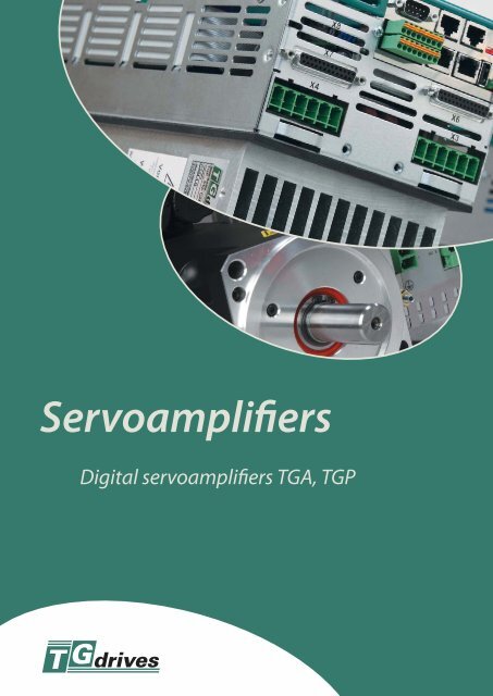
Servoamplifiers<br />
Digital <strong>servoamplifiers</strong> <strong><strong>TG</strong>A</strong>, <strong><strong>TG</strong>P</strong>
Digital <strong>servoamplifiers</strong> <strong><strong>TG</strong>A</strong>_300<br />
Digital <strong>servoamplifiers</strong> <strong><strong>TG</strong>A</strong>_300 are designed for driving rotary <strong>and</strong> linear<br />
synchronous servomotors. Servoamplifiers <strong><strong>TG</strong>A</strong>_300 are equipped with<br />
multiple inputs for communication with many types <strong>of</strong> positioning sensors.<br />
This gives us the possibility to find an optimum priced solution <strong>of</strong> used<br />
feedback sensors.<br />
Digital <strong>servoamplifiers</strong> <strong><strong>TG</strong>A</strong>_300 are designed to be easily connected to<br />
different control systems, because <strong>of</strong> this the <strong>servoamplifiers</strong> can be used in<br />
many applications. In relation to the application <strong>and</strong> control system used, it<br />
is possible to utilize the integrated motion functions or to use only the basic<br />
functions <strong>of</strong> control loops. A huge selection <strong>of</strong> expansion cards enable the<br />
<strong><strong>TG</strong>A</strong>_300 to connect to digital <strong>servoamplifiers</strong> with most available integrated<br />
interfaces (CANopen, PROFIBUS DP, SERCOS, EtherCat).<br />
Digital <strong>servoamplifiers</strong> <strong><strong>TG</strong>A</strong>_300 :<br />
analogue voltage +/-10V for<br />
speed or torque control<br />
Digital control inputs (4) <strong>and</strong> outputs<br />
(2) - activation <strong>of</strong> programmed<br />
position pr<strong>of</strong>iles.<br />
control signals for step motors<br />
„STEP“ <strong>and</strong> „DIRECTION“<br />
control in the form <strong>of</strong> an electronic<br />
gear-box<br />
control using the RS232 communication<br />
interface, CANopen<br />
control using expansion cards<br />
<strong><strong>TG</strong>A</strong>_300 can be connected to the<br />
following position sensors:<br />
Resolver-EnDAT<br />
(single-turn or multi-turn)<br />
Hiperface<br />
(single-turn or multi-turn)<br />
A sensor with sincos signals<br />
An Incremental sensor<br />
with commutative signals.<br />
The possibility to simultaneously<br />
connect two sensors<br />
(e.g. resolver <strong>and</strong> sincos)<br />
Other properties<br />
<strong>of</strong> servoamplifier:<br />
Digital current (32,25µs ..62,5µs),<br />
speed (62,5µs) <strong>and</strong> position loops<br />
(125µs) ensure high motion<br />
dynamics <strong>and</strong> recursion <strong>of</strong> set<br />
operation movements.<br />
The <strong><strong>TG</strong>A</strong>_300 <strong>servoamplifiers</strong> are<br />
equipped with an anti-interference<br />
network filter (class A).<br />
A built in internal brake resistor (with<br />
the ability to connect to external one).<br />
Control <strong>of</strong> the motor holding brake.<br />
Input (AS-enable) for the blocking <strong>of</strong><br />
repeated running.<br />
The versatility <strong>of</strong> use is increased by<br />
the wide spectrum <strong>of</strong> supply voltages<br />
1x115 – 3x230V for the 230V version<br />
<strong>and</strong> 3x208 – 3x480 V <strong>and</strong> CE, UL<br />
<strong>and</strong> cUL certification.<br />
The control s<strong>of</strong>tware that works under<br />
Windows allows: parameter controlling<br />
<strong>of</strong> the servoamplifier, tracking<br />
current values, oscilloscope function<br />
<strong>and</strong> service drive activation.<br />
2
Operating data<br />
Table <strong>of</strong> parameters for <strong><strong>TG</strong>A</strong>_300<br />
Rated data DIM 303 306* 310* 341 343* 346* 312* 324*<br />
1x110V-10% ... 1x230V+10%<br />
Rated supply voltage<br />
3x187–528 V / 50-60 Hz<br />
V~ 3x110V-10% ... 3x230V+10%<br />
(grounded supply, phase to phase)<br />
50 / 60 Hz 50 / 60 Hz<br />
Rated installed power for S1 operation kVA 1.1 2 3.5 1.1 2 3.5 8.5 16.8<br />
Rated DC bus link voltage V= 135–450 300–675<br />
Rated output current (rms value, ± 3%)<br />
Peak output current (max. approx. 5s, +/-3%)<br />
– at 1 x 110V rated voltage Aef 3 / 5 3 / 5 3 / 5 – – – – –<br />
– at 1 x 230 / 240V rated voltage Aef 3 / 9 4 / 9 4 / 9 – – – – –<br />
– at 3 x 115V mains voltage Aef 3,5 / 9 8 / 15 10 / 20 – – – – –<br />
– at 3 x 230V mains voltage Aef 3 / 9 6 / 15 10 / 20 2 / 4,5 5 / 7,5 6 / 12 12 / 24 24 / 48<br />
– at 3 x 400V mains voltage Aef – – – 1,5 / 4,5 4 / 7,5 6 / 12 12 / 24 24 / 48<br />
– at 3 x 480V mains voltage Aef – – – 1,5 / 4,5 3 / 7,5 6 / 12 12 / 24 24 / 48<br />
Continuous power regen circuit (RBint) W 20 50 50 50 50 50 200 200<br />
Continuous power regen circuit (RBext) max. kW 0,3 1 1 0,3 1 1 2 2<br />
Peak power regen circuit (RBext) max. kW 0,75–3 0,75–3 0,75–3 2,1–9 2,1–9 2,1–9 5–21 5–21<br />
* with fan<br />
Dimensions <strong><strong>TG</strong>A</strong>_300<br />
Model 303 306/310 341 343/346 312 324<br />
Height (with fan) (mm) 246 279 246 279 280 280<br />
Width (mm) 70 70 70 70 70 100<br />
Depth (mm) 171 171 171 171 245 245<br />
Depth with connectors (mm) < 200 < 200 < 235 < 235 < 275 < 275<br />
Additional Interfaces<br />
PROFIBUS-DP – expansion card<br />
The servoamplifier can be operated<br />
through a PROFIBUS DP interface.<br />
This expansion card makes it possible<br />
to transmit setpoint <strong>and</strong> to read actual<br />
values <strong>of</strong> the <strong><strong>TG</strong>A</strong>_300 servoamplifier.<br />
Transmission baud rates are from 187.5 k<br />
Baud to 12 M baud.<br />
SERCOS- expansion card<br />
This expansion card makes it possible to<br />
connect <strong>servoamplifiers</strong> <strong><strong>TG</strong>A</strong>_300 with<br />
the data bus through optical fibers. The<br />
pre-selectable baud rate is 2 or 4 Mbaud.<br />
This expansion card makes it possible<br />
to transmit setpoint <strong>and</strong> to read actual<br />
values with different cycle times (1 to 65<br />
ms) with an additional interpolation <strong>of</strong><br />
the setpoints within the drive.<br />
This enables a synchronization that is<br />
exact to the µs, for fast, precise multi-axis<br />
controling.<br />
EtherCat – Ethernet expansion card<br />
This expansion card connects your<br />
servoamplifier <strong><strong>TG</strong>A</strong>_300 through LAN<br />
to the protocol EtherCat.<br />
DeviceNet- expansion card<br />
A DeviceNet Interface expansion card<br />
can be used as an option to connect<br />
<strong>servoamplifiers</strong> <strong><strong>TG</strong>A</strong>_300 to the data bus.<br />
I/O expansion card<br />
The I/O-expansion card is an extremely<br />
economical way <strong>of</strong> operating servo<br />
controllers under position control for<br />
simple automation tasks.<br />
14 additional digital inputs permit<br />
the selection <strong>and</strong> start <strong>of</strong> the motion<br />
tasks that are stored in the motion-task<br />
memory <strong>of</strong> the Digital <strong>servoamplifiers</strong><br />
<strong><strong>TG</strong>A</strong>_300.<br />
8 digital outputs report the status <strong>of</strong> the<br />
drive to the higher-level control.<br />
Single Axis Controller – The motion<br />
controller option card is the solution for<br />
complex motion controlling.<br />
Enables the <strong><strong>TG</strong>A</strong>_300 digital servoamplifier<br />
to be connected with a PROFIBUS-DP.<br />
This expansion card makes it possible<br />
to transmit setpoint <strong>and</strong> to read actual<br />
values on servoamplifier <strong><strong>TG</strong>A</strong>_300.<br />
Transmission baud rate is up to 2Mbauds.<br />
3
Digital <strong>servoamplifiers</strong><br />
The <strong><strong>TG</strong>P</strong>ower is a servo_drive designed as an intelligent<br />
power module with integrated positioning (62,5µs), velocity<br />
(62,5µs) <strong>and</strong> current (62,5µs) control loop.<br />
The servodrive is optimally designed to be easily connected<br />
to control systems with digital communication. Optimal<br />
price solutions can be met by choosing one, two or three<br />
axes module.<br />
Properties <strong>of</strong> <strong><strong>TG</strong>P</strong>ower<br />
Direct connection to an ordinary<br />
power supply (3x230V to 3x480V)<br />
Direct connection to a special power<br />
supply (3x48-85 V, 3x115-230V)<br />
Built in anti-interference filter<br />
Control <strong>of</strong> the motor holding brake<br />
A built in internal brake resistor (with<br />
the ability to connect an external one)<br />
Interpolation (linear or spline)<br />
in a positioning controller<br />
Communicates via CAN bus-protocol<br />
CANopen<br />
Communicates via network bus with<br />
EtherCAT protocol<br />
Digital inputs for capturing fast actions<br />
occurring at the same time point<br />
Reduced losses due to new space<br />
vector modulation (SVM)<br />
CE, UL, <strong>and</strong> cUL certificate<br />
Input for blocking <strong>of</strong> repeated running<br />
to insure personnel safety, category 4<br />
according to EN 954-1<br />
<strong>and</strong> EN 61508<br />
Feedback<br />
Resolver<br />
EnDAT (single-turn or multi-turn)<br />
Hiperface (single-turn or multi-turn)<br />
A sensor with sincos signals<br />
An incremental sensor with<br />
commutative signals (comcoder)<br />
The possibility to simultaneously<br />
connect two sensors (e.g. resolver<br />
<strong>and</strong> sincos)<br />
Control<br />
Current control – applied current<br />
controller only<br />
Speed control – applied current<br />
<strong>and</strong> speed controller<br />
Position control – applied current,<br />
speed <strong>and</strong> position controller<br />
<strong><strong>TG</strong>P</strong> control (same for all models)<br />
Digital inputs:<br />
Enable (blocking <strong>of</strong>f control circuits)<br />
Lock (blocking <strong>of</strong>f the power supply for IGBT modules rousers)<br />
EN-Brake releasing <strong>of</strong> elmag. brake (release elmag. brake)<br />
5 programmable digital inputs (e.g. position lock)<br />
Digital outputs:<br />
Relay READY<br />
Relay for locking <strong>of</strong> the power supply<br />
2 programmable outputs<br />
Communication:<br />
RS232 Service channel for adjusting all parameters<br />
(applicable in all models)<br />
USB Service channel for adjusting all parameters<br />
(applicable in all models)<br />
CAN Real time motion control through the CANbus<br />
EtherCat Real time motion control through the network bus EtherCat<br />
SSI Real time motion control through serial channel SSI<br />
Modules <strong><strong>TG</strong>P</strong> can be<br />
ordered with these<br />
communication cards:<br />
CAN Communication<br />
through CAN bus<br />
ETH Communication<br />
through EtherCat<br />
UNI Communication<br />
through CAN bus<br />
or EtherCat<br />
SSI Communication<br />
through a fast serial<br />
interface with SSI<br />
protocol<br />
4
Technical data for models 3x48-230V<br />
Description <strong><strong>TG</strong>P</strong>_A310 <strong><strong>TG</strong>P</strong>_E305<br />
DIM 10A/10A/10A 5A/5A/5A<br />
Number <strong>of</strong> axis 3 3<br />
Rated supply voltage V AC<br />
3(1)×44–100 V/45–65 Hz 3(1)×104–276 V/45–65 Hz<br />
Rated installed load for S1 operation kVA 3 6<br />
Rated DC link voltage VDC 60–130 150–360<br />
Rated output <strong>of</strong> current axis 1 (+/- 3%) A rms<br />
10 5<br />
Rated output <strong>of</strong> current axis 2 (+/- 3%) A rms<br />
10 5<br />
Rated output <strong>of</strong> current axis 3 (+/- 3%) A rms<br />
10 5<br />
Peak output <strong>of</strong> current axis 1 (+/- 3%) A rms<br />
20 10<br />
Peak output <strong>of</strong> current axis 2 (+/- 3%) A rms<br />
20 10<br />
Peak output <strong>of</strong> current axis 3 (+/- 3%) A rms<br />
20 10<br />
Max. continuous sum current (cooling) A rms<br />
20 15<br />
Rated load <strong>of</strong> internal regen circuit W 66 66<br />
Peak power regen circuit (ext) W 200 400<br />
Peak power regen circuit W 800 1500<br />
Width mm 114<br />
Height mm 241<br />
Depth (with connectors) mm 255 (300)<br />
Technical data for models 3x230-480V<br />
Description <strong><strong>TG</strong>P</strong>_S120 <strong><strong>TG</strong>P</strong>_S315 <strong><strong>TG</strong>P</strong>_S310 <strong><strong>TG</strong>P</strong>_S315<br />
DIM 20A 10A/15A 10A/10A/10A 10A/10A/15A<br />
Number <strong>of</strong> axis 1 2 3 3<br />
Rated supply voltage V AC<br />
3×207–528 V/45–65 Hz<br />
Rated installed load for S1 operation kVA 14 14 14 14<br />
Rated DC link voltage VDC 290–690<br />
Rated output <strong>of</strong> current axis 1 (+/- 3%) A rms<br />
20 10 10 10<br />
Rated output <strong>of</strong> current axis 2 (+/- 3%) A rms<br />
– 15 10 10<br />
Rated output <strong>of</strong> current axis 3 (+/- 3%) A rms<br />
– – 10 15<br />
Peak output <strong>of</strong> current axis 1 (+/- 3%) A rms<br />
40 20 20 20<br />
Peak output <strong>of</strong> current axis 2 (+/- 3%) A rms<br />
– 30 20 20<br />
Peak output <strong>of</strong> current axis 3 (+/- 3%) A rms<br />
– – 20 30<br />
Max. continuous sum current (cooling) A rms<br />
20 20 20 20<br />
Rated load <strong>of</strong> internal regen circuit W 200 200 200 200<br />
Peak power regen circuit (ext) W 1500 1500 1500 1500<br />
Peak power regen circuit kW 6,5–27<br />
Width mm 158<br />
Height (with connectors) mm 378 (472)<br />
Depth mm 235<br />
5
DIGITAL SERVOAMPLIFIERS <strong><strong>TG</strong>A</strong>-24-9/20<br />
<strong><strong>TG</strong>A</strong>-24-9/20 controllers are designed to operate AC synchronous servomotors<br />
<strong>of</strong> up to 150W. A power supply <strong>of</strong> 24VDC allows the <strong>servoamplifiers</strong> to be<br />
used in applications, where it is not possible to supply a voltage <strong>of</strong> 230 / 400V<br />
AC e.g. in mobile equipment or in environments that require safe voltages to<br />
be used.<br />
A high-performance processor ensures not only high quality, accuracy, control<br />
<strong>and</strong> dynamics <strong>of</strong> the servomotor but also ensures a selection <strong>of</strong> user functions<br />
that allow the universal utilization <strong>of</strong> the servomotor.<br />
A digital current loop (current measuring, vector control, position measuring<br />
from a resolver) is calculated every 62,5µs, speed loop is calculated every<br />
250µs, position is calculated every 1ms.<br />
Operating modes<br />
The <strong><strong>TG</strong>A</strong> servoamplifier can operate<br />
in the following modes:<br />
Torque control<br />
Speed control<br />
Absolute positioning<br />
Relative positioning<br />
Pulse <strong>and</strong> direction signals control<br />
(stepper-motor control)<br />
Electronic gearing<br />
Continuous control via CAN-BUS<br />
Communication<br />
The <strong><strong>TG</strong>A</strong> servoamplifier is able to communicate<br />
via the RS 232 serial interface,<br />
RS 485 (422) - protocol MODBUS<br />
<strong>and</strong> via CAN BUS.<br />
Inputs / outputs<br />
The <strong><strong>TG</strong>A</strong> is equipped with 8 digital<br />
inputs, 4 digital outputs, 1 analogue<br />
input (+/-10V or 0-5V or 0-10V), 2 fast<br />
configurable count inputs/outputs.<br />
Parameter settings,<br />
status monitoring<br />
The SETUP program (included in the<br />
delivery) allowing parameter settings<br />
<strong>and</strong> status monitoring using a PC.<br />
The program SETUP is executable under<br />
Windows operating systems <strong>and</strong> communicates<br />
with the <strong><strong>TG</strong>A</strong> servoamplifier via<br />
the RS 232 serial interface.<br />
Operation<br />
The <strong><strong>TG</strong>A</strong> servoamplifier can be operated<br />
using:<br />
Analog voltage – torque or speed<br />
Stepper-motor signals (pulse <strong>and</strong><br />
direction)<br />
Digital inputs – start <strong>of</strong> programmable<br />
position or speed pr<strong>of</strong>iles<br />
Digital control by serial interface<br />
RS 232 (422 / 485) or by CAN-BUS<br />
(torque, speed, position pr<strong>of</strong>iles etc.)<br />
Firmware - customized<br />
We <strong>of</strong>fer customized firmware made<br />
for special applications. The <strong><strong>TG</strong>A</strong><br />
Firmware Loader is a program that allows<br />
new firmware to be uploaded to the<br />
<strong><strong>TG</strong>A</strong> servoamplifier via the RS 232 serial<br />
interface. The firmware upload takes<br />
several seconds.<br />
Mechanical design:<br />
The L-section allows variable mounting<br />
<strong>of</strong> the servoamplifier to the switchboard<br />
or directly to the machine.<br />
6
Technical data <strong>of</strong> <strong>servoamplifiers</strong> <strong><strong>TG</strong>A</strong>-24-9/20<br />
<strong><strong>TG</strong>A</strong>-24-9/20<br />
Parameters Unit Data<br />
Rated supply voltage V = 24 (15–42)<br />
Rated installed load for S1 operation W 230<br />
Rated output current A rms<br />
9<br />
Peak output current (max. ca 5 s) A rms<br />
18,5<br />
Overvoltage protection threshold (transil) V 47<br />
Loss at rated load W 20<br />
Fusing<br />
Supply 24 VDC<br />
Inputs / outputs<br />
Analog input, resolution 12 bit<br />
Input resistance<br />
Digital inputs with adjustable function<br />
24 VDC<br />
Digital outputs with adjustable function,<br />
24 VDC, PNP<br />
– internal – T 10 A<br />
– external – C 8 A<br />
V 0–5 / 0–10/ ±10 V<br />
kΩ 6.6<br />
qty 8<br />
V low 0–5/high 7–30<br />
mA 6<br />
qty 4<br />
V max. 36<br />
mA 25<br />
Counter inputs for IRC<br />
or stepper-motor signals<br />
– 5V (RS422)<br />
Connectors<br />
Control signals – Interhart 3.81, 1.5 mm 2<br />
Power – Interhart 5.08, 2.5 mm 2<br />
Resolver input – Interhart 3.81, 1.5 mm 2<br />
Communication – SubD 9-pole plug<br />
Mechanical data<br />
Weight kg 0.6<br />
Dimensions without connectors mm 157×86×40<br />
Environment<br />
Operating temperature °C 0–40<br />
Relative humidity % max. 85<br />
7
Digital <strong>servoamplifiers</strong><br />
AC brushless servomotors<br />
Universal PC based control system<br />
This project shall be co-financedby the European Fund<br />
for Regional Development<strong>and</strong> by the Ministry <strong>of</strong> Trade <strong>and</strong> Industry.<br />
8<br />
<strong>TG</strong> <strong>Drives</strong> s. r. o., Jeneweinova 37, CZ-617 00 Brno,<br />
tel. (+420) 545 234 935, fax (+420) 545 234 735<br />
info@tgdrives.cz<br />
www.tgdrives.cz


