A summary of KEPCO's 345kV Marine Transmission Line Project
A summary of KEPCO's 345kV Marine Transmission Line Project
A summary of KEPCO's 345kV Marine Transmission Line Project

Create successful ePaper yourself
Turn your PDF publications into a flip-book with our unique Google optimized e-Paper software.
A <strong>summary</strong> <strong>of</strong> KEPCO’s <strong>345kV</strong> <strong>Marine</strong> <strong>Transmission</strong> <strong>Line</strong> <strong>Project</strong><br />
Tai young Kim, Byung ho Kim and Chan hyeong Park<br />
Power System construction <strong>of</strong>fice, KEPCO<br />
5, 2Ga Namdaemoon-Ro Jung-Gu, Seoul, 100-092<br />
Abstract<br />
This paper describes the <strong>summary</strong> <strong>of</strong> design and construction technologies about KEPCO’s <strong>345kV</strong> marine transmission<br />
line. This has been operating commercially since July 2004 in Korea. We designed and constructed this line to supply the<br />
enormous electric power stably from the Yonghung thermal power plant into the metropolitan area. We considered this<br />
project in all aspects very deeply to decide design conditions and construction methods such as the electric environmental<br />
design, insulation design, conductor design, selection <strong>of</strong> tower types and material, design <strong>of</strong> insulator strings, foundation<br />
design, erection, wiring and so on because it crossed the western sea and lake Siwha about twenty five kilometers and<br />
moreover we had not yet experienced in making a great plan <strong>of</strong> <strong>345kV</strong> marine transmission line like this until now.<br />
Keyword : <strong>345kV</strong>, marine, transmission, technology<br />
1. INTRODUCTION<br />
Since the very first light bulb was lit in our country in<br />
1887, we KEPCO have been contributing to industrial<br />
development in Korea and improvements in the quality<br />
<strong>of</strong> life for the nation by producing and providing high<br />
quality electricity at very competitive prices for the past<br />
century. The total consumption <strong>of</strong> electric power in<br />
Korea is currently 51.3 million kilowatts, 45 percent <strong>of</strong><br />
which is being consumed in Seoul and the metropolitan<br />
areas. Recently most <strong>of</strong> the electric power supplied to<br />
metropolitan area has been transported from the power<br />
plants located in southern and far eastern parts <strong>of</strong> the<br />
Korea.<br />
In this paper we would like to introduce the design &<br />
construction methods <strong>of</strong> the <strong>345kV</strong> marine Yonghung<br />
transmission line that has been developed with pure<br />
domestic technologies.<br />
MY T/L outline is as following.<br />
- Total length <strong>of</strong> line is about 39km (25km on the sea)<br />
- Its power supply capacity is 12,000MW<br />
- Steel pipe 137 towers (89 on the sea), 21,000 tons totally<br />
80 ~ 165m high<br />
- Wires are required approximately 1,900km.<br />
- Used 6 types <strong>of</strong> porcelain insulators such as 210kN,<br />
300kN, 400kN and Normal, Fog and totally 83,145<br />
- Generating capacity <strong>of</strong> Yonghung Plant is 6,400MW<br />
2. MAIN DISCUSSION<br />
2.1 Outline <strong>of</strong> <strong>Transmission</strong> line<br />
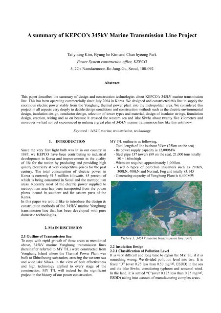
To cope with rapid growth <strong>of</strong> those areas as mentioned<br />
above, <strong>345kV</strong> marine Yonghung transmission lines<br />
(hereinafter referred to MY T/L) were constructed from<br />
Yonghung Island where the Thermal Power Plant was<br />
built to Shinsiheung substation, crossing the western sea<br />
and wide lake Sihwa. In the view <strong>of</strong> both effectiveness<br />
and high technology applied to every stage <strong>of</strong> the<br />
construction, MY T/L will indeed be the significant<br />
project in the history <strong>of</strong> our power construction.<br />
Picture 1. <strong>345kV</strong> marine transmission line route<br />
2.2 Insulation Design<br />
2.2.1 Classification <strong>of</strong> Pollution Level<br />
It is very difficult and long time to repair the MY T/L if it is<br />
something wrong. We divided pollution level into two. It is<br />
fixed “D” (over 0.25 less than 0.50 mg/cm2, ESDD) in the sea<br />
and the lake Siwha, considering typhoon and seasonal wind.<br />
In the land, it is settled “C”(over 0.125 less than 0.25 mg/cm2,<br />
ESDD) taking into account <strong>of</strong> manufacturing complex areas.
2.2.2 Number <strong>of</strong> insulator <strong>of</strong> strings<br />
We used the resistance voltage method to calculate the<br />
number <strong>of</strong> insulator <strong>of</strong> strings instead <strong>of</strong> IEC 60815. The<br />
resistance voltage <strong>of</strong> insulator for <strong>345kV</strong> is 251kV.<br />
362 kV × 3 × 1.2 = 251kV<br />
The number <strong>of</strong> insulator can be given that the resistance<br />
voltage divided by each insulator resistance voltage.<br />
The number <strong>of</strong> insulator is shown as following table 1.<br />
Items<br />
Sea<br />
lake<br />
Land<br />
Table 1. Number <strong>of</strong> insulator<br />
Number <strong>of</strong> insulator<br />
Type <strong>of</strong><br />
Insulator<br />
Salt fog<br />
(0.5mg/cm2)<br />
Salt fog<br />
(0.25mg/cm2)<br />
Number Number<br />
210kN 27<br />
300kN 23<br />
400kN 28<br />
210kN 24<br />
300kN 27<br />
2.2.3 Insulator device<br />
After the study <strong>of</strong> insulator strength, suspension type<br />
insulator was determined 210kN x 2 strings on condition<br />
that the horizontal span was less than 700m in the sea<br />
section. If the horizontal span exceeded 700m, it would<br />
be 300kN x 2 strings. For the strain type insulator, it<br />
would be 400kN x 2 strings. In case <strong>of</strong> the land section,<br />
suspension type insulator was selected 210kN x 2 strings<br />
and strain type insulator was 300kN x 2 strings.<br />
2.2.4 Arcing Horn<br />
Arcing horn gap <strong>of</strong> insulator is the basic element in the<br />
calculation <strong>of</strong> insulation distance. After considering the<br />
required gap distance and horn efficiency by switching<br />
over voltage and lightning surge, the arcing horn gap was<br />
calculated. In case <strong>of</strong> <strong>345kV</strong> marine <strong>Transmission</strong> line, it<br />
didn’t only cross the sea section with no shelter, but also<br />
there was some chance for lightning to concentrate on<br />
the transmission line when lightning occurs, because <strong>of</strong><br />
height <strong>of</strong> tower. And it was very important for <strong>345kV</strong><br />
marine <strong>Transmission</strong> line to transport a large capacity <strong>of</strong><br />
electricity. So we should reduce lightning flashover rate.<br />
Table 2. Comparison <strong>of</strong> the lightning accident rate<br />
Items<br />
Horn distance<br />
2,730mm 3,000mm 3,200mm Ref.<br />
1 1.5560 1.1893 1.0118<br />
2 1.3229 1.0065 0.8577<br />
Item 1: All lightning Accident rate<br />
Item 2: All lightning Accident rate except special type<br />
As you see the table 2, to maintain the lightning accident<br />
rate within one, it was recommended that arcing distance<br />
was 3,000mm and installed SBI(lightning protector<br />
device) in special tower.<br />
2.2.5 Pre-fabricated Jumper<br />
We selected Pre-fabricated jumper while horizontal angle<br />
was below 40 degrees. If horizontal angle exceeded 40°,<br />
we used string jumper or ‘V’ string. Pre-fabricated<br />
jumper was used to improve work efficiency, because<br />
thick conductor had been a problem to be formed and<br />
handled. Pre-fabricated jumper supported jumper<br />
conductor with spacer at the horizontal member. Prefabricated<br />
jumper could decrease height <strong>of</strong> tower because<br />
it maintained jumper conductor with horizon. It didn’t<br />
need to have restraint swing reinforced conductor and it<br />
was easy to control insulator distance through the<br />
support device adjustment.<br />
Picture 2. Pre-fabricated jumper<br />
2.2.6 Length <strong>of</strong> Strings and depth <strong>of</strong> jumper<br />
The length <strong>of</strong> suspension strings was 5,129 mm(210kN),<br />
5,670mm(210kN) in land but 5,870mm(300kN) in sea.<br />
The depth <strong>of</strong> jumper was 3,740mm applied to 110% <strong>of</strong><br />
the standard insulator distance<br />
(1.115 x 3,000 + 21) x 110% = 3,740 mm<br />
Table 3. Length <strong>of</strong> Strings (suspension type)<br />
Items<br />
Land Sea and lake<br />
210kN 210kN 300kN<br />
1 686 mm 686 mm 858 mm<br />
2 4,080 mm 4,590 mm 4,485 mm<br />
3 363 mm 363 mm 509 mm<br />
4 5,129 mm 5,639 mm 5,852 mm<br />
5 5,170 mm 5,670 mm 5,852 mm<br />
Item 1: Hardware distance at arm<br />
Item 2: Length <strong>of</strong> Insulator strings<br />
Item 3: Hardware distance at conductor<br />
Item 4: calculated distance<br />
Item 5: total distance, Considering a margin<br />
2.3 Design <strong>of</strong> Conductor<br />
2.3.1 Selection <strong>of</strong> Conductor<br />
The new type <strong>of</strong> conductor was developed and used for<br />
this marine project, considering the characteristics <strong>of</strong> the<br />
construction areas. In some cases, it was impossible to<br />
avoid long distance span between the two towers.<br />
Therefore it was selected as HTACSR/AW, High-
Strength Thermal-resistant Aluminum-alloy Conductors<br />
Aluminum-clad Steel Reinforced. As a result, capacity <strong>of</strong><br />
transport was improved by 1.5 times compared to that <strong>of</strong><br />
the normal <strong>345kV</strong> transmission line. The span (distance<br />
between two towers) was extended from 350m to 600m,<br />
and tensile strength was improved by 1.6 times from 11<br />
tons to 18 tons.<br />
To select the best suited conductor for marine project, we<br />
were considering four kinds <strong>of</strong> conductors such as<br />
HTACSR/AW 480 mm2 Cardinal, HTACSR/AW 480 mm2<br />
Rail, TACSR/AW 480 mm2 Rail, TACSR/AW 480 mm2<br />
Cardinal. After studying many kinds <strong>of</strong> the factors such<br />
as capacity <strong>of</strong> transport, mechanical strength and<br />
economical efficiency. We finally selected HTACSR/AW<br />
480 mm2 x 4 bundles (Cardinal) for the sea section and<br />
TACSR/AW 480 mm2 x 4 bundles (Rail) for the land<br />
section.<br />
Table 4. Character <strong>of</strong> conductor<br />
Items unit TACSR/AW HTACSR/AW<br />
Stranding<br />
Num/ Al 45/3.7 54/3.38<br />
mm St 7/2.47 7/3.38<br />
Area mm2<br />
Al 483.84 484.53<br />
St 33.54 62.81<br />
Ultimate<br />
Strength<br />
kgf 11,260 18,880<br />
Diameter mm<br />
Al 29.61 30.42<br />
St 7.41 10.14<br />
Weight kg/km 1,561 1,756<br />
Resistance Ω/km 0.0595 0.0633<br />
Temperature ℃ 150(max) 150 (max)<br />
Permitted<br />
current<br />
A 1,431(max) 1,411(max)<br />
Elastic coef kg/mm2 6,910 7,570<br />
Coefficient /℃ 21.5x10 -6 20.5x10 -6<br />
2.3.2 Capacity <strong>of</strong> Transport<br />
Conductor should satisfy the 1,712 MW capacity <strong>of</strong><br />
transport because the whole generating power <strong>of</strong> the<br />
Yonghung power plant was 6,400MW. We planned<br />
four(4) circuits <strong>of</strong> marine transmission line.<br />
Table 5. Capacity <strong>of</strong> transport<br />
Items<br />
TACSR/AW HTACSR/AW<br />
(Rail) (Cardinal)<br />
1 1,431 A 1,411 A<br />
2 3,078 MW 3,035 MW<br />
3 111 % 113 %<br />
Item 1 : Continuous Current Capacity<br />
Item 2 : Thermal Capacity <strong>of</strong> continuous current capacity<br />
Item 3 : Overload Rate compared to thermal capacity for<br />
one root accident(%)<br />
Two types <strong>of</strong> conductors were all satisfied the capacity <strong>of</strong><br />
transport because overload rate compared to thermal<br />
capacity for the one root accident is below 150%.<br />
2.3.3 Ground Wire<br />
Ground wire should be able to allow fault current to flow<br />
when transmission line is failed. Ground wire tension<br />
was determined to ensure that the sag at the lowest<br />
temperature with no wind should not exceed 80% <strong>of</strong> the<br />
conductor sag. By thinking over the induced current,<br />
maximum fault current and mechanical characteristic, we<br />
selected two conductors, AW 200 mm2 and OPGW 200 mm2.<br />
2.3.4 Boltless type spacer damper<br />
It is very difficult to maintain marine transmission lines,<br />
because the towers were located on the sea. And we had<br />
a few troubles with bolt type spacer damper in the past.<br />
So the boltless type spacer dampers were developed to<br />
prevent bolts from getting too loose. There are no<br />
chances for these dampers to damage ACSR conductors.<br />
2.4 Foundation Design<br />
KEPCO adopted two special foundation methods to set<br />
the tower in the sea. We selected Jacket Pile method and<br />
altered it into individual jacket pile method. It was a safe<br />
method to withstand any load <strong>of</strong> tower, wind load etc.<br />
Picture 3. Jacket pile method<br />
Steel Pipe Concrete method was used in lake Sihwa<br />
where the “Jacket Pile” method could not be used and<br />
some areas where the layer <strong>of</strong> the ground was not<br />
suitable to support the structure. This method was highly<br />
stable and cost effective.<br />
Picture 4. Steel Pipe Concrete method
2.5 Tower Design<br />
As tower materials are mostly used angle steel until now,<br />
some problems happened in the maintenance and<br />
construction because the towers are getting bigger due to<br />
the shape <strong>of</strong> double-post. To resolve these problems in<br />
the MY T/L, the steel pipe was fixed for safety and<br />
reliability after studying the merits and demerits in using<br />
the angle steel and the steel.<br />
2.6 Construction Works<br />
2.6.1 Erection<br />
Towers are steel pipe. Generally we used a tower crane<br />
to erect tower. Huge tower was over 150m high, it could<br />
not be accomplished by ordinary tower crane. It was<br />
required special cranes. We applied new method to erect<br />
tower in the sea. It needed many kinds <strong>of</strong> equipment as<br />
follows.<br />
- one towboat<br />
- three barges : set a crane, transport and store material<br />
- hydraulic truck crane, crawler crane, tower crane.<br />
300ton class sea cranes are used to erect towers in the sea.<br />
Hydraulic crane that was set on barges were used for<br />
towers up to 80m, and tower cranes were used for towers<br />
over 80m<br />
Picture 6. Drum site on the barge<br />
2.7. Environment-Friendly Design<br />
Deliberations with the Aviation Administration and local<br />
<strong>of</strong>ficials resulted in the hiring <strong>of</strong> a color specialist who<br />
designed the different colors used in painting the towers<br />
to match the various characteristics <strong>of</strong> the areas. We<br />
painted towers blue-green color in seashore area and<br />
light yellow color in cultural asset area, light blue color<br />
in factory area, light green color in resident areas, graygreen<br />
in farm land, blue-green in sea light.<br />
To remind people living nearby about the transmission<br />
line <strong>of</strong> environment-friendly tower, we established shape<br />
<strong>of</strong> bird and lighted it at night. And we installed nighttime<br />
viewable illumination in lake Sihwa to protect birds and<br />
improve image <strong>of</strong> electricity facilities<br />
2.8 Air Pollution Counter Plan<br />
Because some <strong>of</strong> the transmission line went adjacent to<br />
manufacturing complex areas, there will be a corrosion<br />
<strong>of</strong> the tower, conductor and hardware attached with SO 2<br />
(sulfurous acid gas ) , NO 2 (nitrogenous oxide), T.S.P (total<br />
suspended particle). After consulting with the specialist,<br />
we made countermeasures as the following.<br />
Picture 5. Tower Erection<br />
2.6.2 Wiring<br />
A large part <strong>of</strong> MY T/L route crosses bodies <strong>of</strong> water, so<br />
different wiring methods were developed. Helicopters<br />
and floating cranes helped install and separate electric<br />
wires from the surface <strong>of</strong> the sea during the wiring stages<br />
<strong>of</strong> the sections between Yonghung Island and Sunjae<br />
Island where ships passes. Floating platforms were used<br />
to perform this same task during wiring work in lake<br />
Sihwa. To reduce the amount <strong>of</strong> work to be done in the<br />
air above the sea while wiring and stringing wires, a<br />
compromise method was used that was combining<br />
conventional method and Pre-fabricated method.<br />
This plan not only helped reduce working time but also<br />
improved quality and wire loss. When working on<br />
tension towers, wire compression works ere done about<br />
50% on the ground.<br />
Table 6. Countermeasure against air pollution<br />
Items T.S.P Condition Counter measure<br />
Tower Not clean by water painting<br />
Insulator Can clean by water Install water pipe<br />
Hardware<br />
Conductor<br />
Spacer<br />
Jumper<br />
possible to clean by<br />
water<br />
- remove TSP<br />
by brushing<br />
- coating<br />
2.9 <strong>Transmission</strong> Tower Exposure Test<br />
We had built the transmission tower exposure test site in<br />
lake Siwha to improve life management <strong>of</strong> towers in the<br />
MY T/L through assessment <strong>of</strong> corrosion protection and<br />
concrete durability.<br />
Test methods are as follows.<br />
- Degradation evaluation <strong>of</strong> steel material coating<br />
- Corrosion evaluation <strong>of</strong> steel material<br />
- Concrete durability evaluation<br />
- Lifetime analysis <strong>of</strong> Corrosion pro<strong>of</strong> facility
4. REFERENCES<br />
[1] Lee, sang-gyu etc, “The technology book <strong>of</strong> <strong>345kV</strong><br />
yonghung transmission line project”, vol 1, 2003<br />
[2] Kim, tai-young etc, “The technology book <strong>of</strong> <strong>345kV</strong><br />
yonghung transmission line project”, vol 2, 2004<br />
[3] “Manual for transmission tower exposure test”<br />
KEPCO, August 2004<br />
Picture 7. <strong>Transmission</strong> Tower Exposure Test<br />
We had organized special team to make a systematic<br />
study <strong>of</strong> the MY T/L, made a manual how to inspect<br />
material samples in the <strong>Transmission</strong> Tower Exposure<br />
Test. We have been studying all gained data and<br />
analyzing the effects <strong>of</strong> the steel material degradation<br />
and corrosion, concrete durability and Lifetime <strong>of</strong> facility.<br />
3. CONCLUSION<br />
MY T/L performed by purely domestic technologies<br />
was completed in June <strong>of</strong> 2004, we have no error until<br />
now. It means that we have independent technologies<br />
on the design and construction <strong>of</strong> the ultra highvoltage<br />
transmission facilities in the sea as well as the<br />
facility reliability improvement by making regular<br />
interval tests and progressing the technologies on the<br />
design, construction, project management and check<br />
& test based on power transmission construction<br />
experience accumulated for the last 30 years.<br />
Picture 8. View <strong>of</strong> erected towers in the sea