

Download My SINUMERIK Operate - CNC4you - Siemens
Download My SINUMERIK Operate - CNC4you - Siemens
Download My SINUMERIK Operate - CNC4you - Siemens

You also want an ePaper? Increase the reach of your titles
YUMPU automatically turns print PDFs into web optimized ePapers that Google loves.
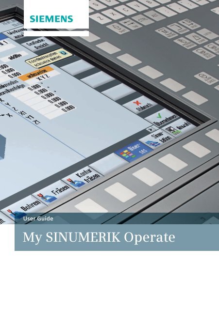
User Guide<br />
<strong>My</strong> <strong>SINUMERIK</strong> <strong>Operate</strong>
Contents<br />
1 Introduction......................................................................... 7<br />
2 <strong>SINUMERIK</strong> <strong>Operate</strong>............................................................. 9<br />
2.1 Uniform user interface for turning and milling..................................... 10<br />
2.2 Help screens, animated elements, graphic view, tooltips, help............ 14<br />
2.3 TSM mode/zero offsets....................................................................... 16<br />
2.4 Programming..................................................................................... 17<br />
2.5 Tool management.............................................................................. 21<br />
2.6 Zero offset......................................................................................... 24<br />
2.7 Program management........................................................................ 25<br />
2.8 Workpiece visualization (simulation and mold making view)................ 29<br />
2.9 CNC operation in Automatic mode (AUTO) ......................................... 31<br />
3 Turning technology............................................................ 35<br />
3.1 Setting up.......................................................................................... 36<br />
3.1.1 Setting the zero point...................................................................... 36<br />
3.1.2 Workpiece zero............................................................................... 37<br />
3.1.3 Tool measurement.......................................................................... 37<br />
3.2 Programming..................................................................................... 40<br />
3.2.1 ShopTurn........................................................................................ 40<br />
3.2.2 programGUIDE................................................................................ 42<br />
3.3 Drilling.............................................................................................. 44<br />
3.3.1 Overview of drilling cycles .............................................................. 44<br />
3.3.2 Drilling centered/off-centered with ShopTurn................................... 47<br />
3.3.3 Drilling with programGUIDE............................................................. 49<br />
3.4 Turning.............................................................................................. 51<br />
3.4.1 Overview of the turning cycles......................................................... 51<br />
Contents 3
3.5 Contour turning................................................................................. 54<br />
3.5.1 Overview of the turning cycles for the contour machining................... 54<br />
3.5.2 Contour turning with ShopTurn machining step programming.......... 55<br />
3.5.3 Contour turning with programGUIDE................................................ 57<br />
3.6 Milling............................................................................................... 60<br />
3.6.1 Overview of the milling cycles.......................................................... 60<br />
3.7 Contour milling.................................................................................. 63<br />
3.7.1 Overview of the milling cycles for the contour machining....................63<br />
3.7.2 Contour milling with ShopTurn machining step programming........... 65<br />
3.7.3 Contour milling with programGUIDE................................................ 67<br />
3.8 Counterspindle.................................................................................. 70<br />
3.9 Measuring in the Automatic mode - in-process measurement.............. 71<br />
3.9.1 Measure workpiece......................................................................... 71<br />
3.9.2 Example.......................................................................................... 72<br />
4 Milling technology............................................................. 75<br />
4.1 Setting up.......................................................................................... 76<br />
4.1.1 Setting the zero point...................................................................... 76<br />
4.1.2 Workpiece zero............................................................................... 77<br />
4.1.3 Tool measurement.......................................................................... 78<br />
4.1.4 Face milling.................................................................................... 79<br />
4.1.5 Swiveling in JOG............................................................................. 80<br />
4.2 Programming..................................................................................... 81<br />
4.2.1 ShopMill machining step programming............................................ 81<br />
4.2.2 programGUIDE................................................................................ 83<br />
4.3 Drilling cycles.................................................................................... 85<br />
4.4 Milling cycles..................................................................................... 88<br />
4.5 Contour milling.................................................................................. 92<br />
4.5.1 Overview of the milling cycles for the contour machining....................92<br />
4.5.2 Contour milling with ShopMill machining step programming............ 94<br />
4.5.3 Contour milling with programGUIDE................................................ 96<br />
4.6 Miscellaneous.................................................................................... 99<br />
4.7 Measuring in the Automatic mode – in-process measurement........... 103<br />
4.7.1 Measure workpiece....................................................................... 103<br />
4.7.2 Measure tool................................................................................. 105<br />
4
5 Multitasking (with <strong>SINUMERIK</strong> 840D sl)........................... 107<br />
5.1 Tool management............................................................................ 108<br />
5.2 Turning-milling technology with ShopTurn and programGUIDE.......... 109<br />
5.2.1 Swivel axis in TSM mode................................................................ 109<br />
5.2.2 Turning with ShopTurn and B axis.................................................. 109<br />
5.2.3 Turning with programGUIDE and B axis.......................................... 110<br />
5.2.4 Milling with ShopTurn and B axis................................................... 110<br />
5.2.5 Milling with programGUIDE and B axis............................................ 112<br />
5.3 Milling-turning technology with programGUIDE.................................114<br />
5.3.1 Align turning tool.......................................................................... 114<br />
5.3.2 Overview of the turning cycles in the milling technology................ 115<br />
5.3.3 Contour turning in the milling technology...................................... 118<br />
5.3.3.1 Overview of the contour turning cycles in programGUIDE............ 118<br />
5.3.3.2 Contour turning with programGUIDE in the milling technology.... 120<br />
5.4 Multi-channel machining...................................................................124<br />
5.4.1 Machine basic screen.................................................................... 124<br />
5.4.2 programSync multi-channel........................................................... 125<br />
5.4.3 Multi-channel program data.......................................................... 126<br />
5.4.4 Dual editor.................................................................................... 126<br />
5.4.5 Time synchronization.................................................................... 127<br />
5.4.6 Synchronous view......................................................................... 128<br />
5.4.7 Simulation.................................................................................... 128<br />
5.4.8 Determining the machining time, optimization............................... 129<br />
5.4.9 Program control............................................................................ 130<br />
6 Appendix.......................................................................... 133<br />
6.1 G-Code.............................................................................................133<br />
6.2 Shortcuts......................................................................................... 134<br />
6.3 Further information..........................................................................137<br />
7 Index................................................................................ 139<br />
Contents 5
1 Introduction<br />
The <strong>SINUMERIK</strong> <strong>Operate</strong> user interface provides a clear and intuitive user and<br />
programming interface. This provides a uniform look & feel not only for turning<br />
and milling but also the connection of machining step and high-level language<br />
programming under a single system user interface. <strong>SINUMERIK</strong> <strong>Operate</strong> also<br />
brings new, powerful functions.<br />
This user guide provides you with an overview of the range of functions of<br />
<strong>SINUMERIK</strong> <strong>Operate</strong> and gives you useful tips and tricks for your daily work.<br />
In addition to the <strong>SINUMERIK</strong> <strong>Operate</strong> chapter – with general operating tips –<br />
the other chapters give practical expert knowledge for the milling, turning and<br />
working with multitasking machines. The appendix contains an overview of the<br />
<strong>SINUMERIK</strong> <strong>Operate</strong> shortcuts and an overview of G code commands.<br />
Introduction 7
2 <strong>SINUMERIK</strong> <strong>Operate</strong><br />
<strong>SINUMERIK</strong> <strong>Operate</strong> has a uniform operating and programming interface with<br />
powerful functions for turning and milling. The functions and operating instructions<br />
described in this chapter therefore apply irrespective of whether you work<br />
on a turning or a milling machine or at a machining center.<br />
<strong>SINUMERIK</strong> <strong>Operate</strong> 9
2.1 Uniform user interface for turning and milling<br />
<strong>SINUMERIK</strong> <strong>Operate</strong> has a uniform operating and programming interface with<br />
powerful functions for turning and milling. The functions and operating instructions<br />
described in this chapter therefore apply irrespective of whether you work<br />
on a turning or a milling machine or at a machining center.<br />
• HMI-Advanced, ShopMill and ShopTurn combined under a single interface<br />
• Intuitive and clear operation and programming, including animated<br />
elements<br />
• Representation in the modern Windows style<br />
• New powerful functions …<br />
· Setup, programming, tool and program management<br />
· for complete machining<br />
· Multi-channel capability with ShopTurn for multi-channel machines,<br />
among other things, synchronization of programs with programSYNC<br />
and much more…<br />
• CNC programming for the highest level of productivity using<br />
programGUIDE<br />
• Machining step programming for the shortest programming time with<br />
ShopMill and ShopTurn<br />
10
The following overview provides an initial introduction to the look & feel of<br />
<strong>SINUMERIK</strong> <strong>Operate</strong>:<br />
Setting-up operation<br />
A single user interface for almost all <strong>SINUMERIK</strong> controllers …<br />
Turning<br />
Milling<br />
<strong>SINUMERIK</strong> <strong>Operate</strong> universal<br />
<strong>SINUMERIK</strong> <strong>Operate</strong> turning<br />
<strong>SINUMERIK</strong> <strong>Operate</strong> milling<br />
<strong>SINUMERIK</strong> <strong>Operate</strong> 11
Tool management<br />
Efficient management of the tool data including all details and sister tool<br />
handling …<br />
Turning<br />
Milling<br />
Program manager<br />
Time savings thanks to user-friendly data transmission and simple program<br />
handling …<br />
Turning<br />
Milling<br />
Backing up<br />
setup data ...<br />
Preview window ...<br />
Multiple clamping for<br />
ShopMill …<br />
12
programGUIDE<br />
Maximum productivity and flexibility in the programming combined with innovative<br />
technology and machining cycles …<br />
Turning<br />
Milling<br />
ShopTurn/ShopMill<br />
In addition to programGUIDE, ShopTurn/ShopMill offers the unique machining<br />
step programming to achieve the shortest programming times in the single-part<br />
production.<br />
Turning<br />
Milling<br />
<strong>SINUMERIK</strong> <strong>Operate</strong> 13
2.2 Help screens, animated elements, graphic view, tooltips,<br />
help<br />
Help screens ...<br />
A help screen is displayed for each machining<br />
cycle. The current parameter is color-highlighted<br />
in the help screen.<br />
Animated elements …<br />
Animated elements help you for the parameterization<br />
of cycles with intuitive animation of<br />
the motion sequences.<br />
The animation starts automatically after a few<br />
seconds.<br />
The “Graphic view” softkey can be used to<br />
change to the individual cycle screens or to<br />
call the broken-line graphics for the complete<br />
workpiece.<br />
14
A tooltip is displayed for each input field.<br />
Selection fields are indicated with the additional<br />
symbol in the tooltip.<br />
If an entered value is not permitted, the<br />
tooltip and the input field are displayed in red<br />
font and with a red background, respectively.<br />
The “Help” key fetches the context-sensitive<br />
help that can be used in all screens (also in<br />
the machine data area).<br />
<strong>SINUMERIK</strong> <strong>Operate</strong> 15
2.3 TSM mode/zero offsets<br />
or<br />
In TSM cycle (manual mode), you can, among<br />
other things,<br />
• perform tool change (T) with direct access<br />
via the tool table,<br />
• define the spindle speed and direction (S),<br />
• enter M functions (M),<br />
• activate zero offsets,<br />
• select the machining plane.<br />
With selection fields, such as machining<br />
plane, you can use the “Select” key to make a<br />
selection; clicking any button opens the list.<br />
or<br />
In the “Set ZO” dialog box, you can write<br />
direct position values for individual axes in<br />
the actual value display.<br />
The difference between the position value in<br />
the machine coordinate system (MCS) and the<br />
workpiece coordinate system (WCS) is saved<br />
in the active zero offset.<br />
Note: More information about setup functions in JOG and for in-process measurements<br />
can be found in the appropriate chapters for turning or milling.<br />
16
2.4 Programming<br />
<strong>SINUMERIK</strong> <strong>Operate</strong> provides the appropriate programming method for every<br />
field of application.<br />
ShopMill/ShopTurn programGUIDE programSYNC ISO-Code<br />
workstep<br />
programming<br />
DIN/ISO & <strong>SINUMERIK</strong><br />
high-level language<br />
multi channel<br />
programming<br />
with cycle support<br />
• Designed for<br />
shortest programming<br />
time<br />
• Tailored for single<br />
parts and small<br />
batch sizes<br />
• Designed for maximal<br />
flexibility and<br />
shortest machining<br />
time<br />
• Tailored for medium<br />
to large batch sizes<br />
• Increased productivity<br />
for multi-channel<br />
machines<br />
• Suitable for singlepiece<br />
small-batch<br />
and batch<br />
production<br />
• Designed for maximal<br />
ISO-code<br />
compatibility<br />
• Focused on medium<br />
to large batch sizes<br />
The user and programming interface is uniform for all cycle screen forms irrespective<br />
of whether you use programGUIDE or ShopMill/ShopTurn. The only<br />
difference, the tool call and the technological information are directly integrated<br />
in the cycle for ShopMill/ShopTurn. More detailed information on the cycles is<br />
contained in the turning and milling sections.<br />
Tips for working with the editors and the cycle screens, such as how to structure<br />
programs using blocks, follow.<br />
<strong>SINUMERIK</strong> <strong>Operate</strong> 17
You can configure the editor for ShopMill/<br />
ShopTurn or programGUIDE. Among other<br />
things, you can set whether, for example,<br />
block numbers should be displayed.<br />
If, for example, you want to compare programs<br />
or transfer program sections from one<br />
program to another program, you can open<br />
two programs concurrently.<br />
You can use the “Next window” key to the<br />
switch between the windows.<br />
Click the “Close” softkey to close the second<br />
program.<br />
18
Click the “Find” softkey to start the search in<br />
the editors.<br />
Ctrl+F shortcut<br />
If you select a line before calling the search<br />
screen, the selected text will be transferred to<br />
the search field.<br />
To structure large programs and individual<br />
machining steps, you can form program<br />
blocks in ShopMill/ShopTurn and in programGUIDE.<br />
The lines selected in the editor<br />
are grouped to form a program block.<br />
or<br />
You can open and close the program blocks of<br />
the program.<br />
or<br />
You can use the arrow keys to open and close<br />
individual blocks.<br />
<strong>SINUMERIK</strong> <strong>Operate</strong> 19
You can use parameters and variables to<br />
define the ShopMill/ShopTurn or programGUIDE<br />
cycles.<br />
For more information about defining variables<br />
and the use of parameters, consult the<br />
documentation.<br />
In ShopMill/ShopTurn, the feedrate/speed values<br />
are converted automatically by pressing<br />
the “SELECT” button.<br />
20
2.5 Tool management<br />
or<br />
Tools with their complete operating data can<br />
be managed in the tool list. This includes:<br />
• The tool type (displayed as an icon)<br />
• The unique tool name<br />
(max. 24 characters)<br />
• Number of cutting edges per tool (max. 9)<br />
Tools with the same name are created<br />
as sister tools. In the ST column<br />
(ST = Sister tool), the sister<br />
tools are identified with an incrementing<br />
number.<br />
• Tool length and diameter and/or cutting<br />
plate geometry<br />
• Nose angle for drills or number of teeth<br />
for milling tools<br />
• Direction of spindle rotation and coolant<br />
(level 1 and 2)<br />
or<br />
You can view the tool details, such as tool status,<br />
using the “Details” softkey. The tool is displayed<br />
graphically.<br />
<strong>SINUMERIK</strong> <strong>Operate</strong> 21
or<br />
The tool wear list contains all the information<br />
required during operation.<br />
You can automatically monitor the tools’<br />
working times via the workpiece count, tool<br />
life or wear.<br />
In addition, you can disable tools when you<br />
no longer wish to use them.<br />
The following overview shows the used symbols<br />
and explains the tool status:<br />
Icon/Designation<br />
Red “X”<br />
Yellow triangle pointing<br />
downward<br />
Yellow triangle pointing upward<br />
Green border<br />
Meaning<br />
The tool is disabled.<br />
The prewarning limit has been reached.<br />
The tool is in a special state.<br />
Place the cursor on the marked tool. A<br />
tooltip provides a short description.<br />
The tool is preselected.<br />
Magazine/location number<br />
Green double arrow<br />
Gray double arrow (configurable)<br />
Red “X”<br />
Meaning<br />
The magazine location is positioned at the<br />
change position.<br />
The magazine location is positioned at the<br />
loading position.<br />
The magazine location is disabled.<br />
22
or<br />
When you create new tools, you can select<br />
the relevant tool from clearly arranged tables<br />
for the associated tool types. Among other<br />
things, the favorites are grouped in a separate<br />
table.<br />
Multitools can also be created when a milling<br />
spindle or a dual tool holder is used.<br />
or<br />
Click the “Find” softkey to open the tool<br />
search. You can search for tools, magazine<br />
locations or empty locations.<br />
Ctrl+F shortcut<br />
<strong>SINUMERIK</strong> <strong>Operate</strong> 23
2.6 Zero offset<br />
This view shows in a single screen all zero offsets<br />
and frames, incl. details, active at<br />
runtime.<br />
Rotations, scaling and mirroring also shown<br />
as icons<br />
Active zero offsets can be edited in the<br />
Reset status.<br />
This view shows an overview of all offsets.<br />
All settable offsets, divided into coarse and<br />
fine offsets, are displayed in the “Zero Offset -<br />
G54..G599” window. Rotation, scaling and<br />
mirroring are displayed.<br />
24
2.7 Program management<br />
You can use the program manager to manage<br />
folders and programs in a similar manner as<br />
the Windows Explorer.<br />
Functions, such as copy and select, can be<br />
found on the vertical softkey bar.<br />
Active programs have a green background.<br />
The storage capacity of the external memory<br />
media or the NC memory is displayed at the<br />
lower right.<br />
You can directly access all connected drives/<br />
network drives.<br />
The shortcuts for program management<br />
can be found in the appendix.<br />
or<br />
You can create folders and programs in a tree<br />
structure (on local drives). The program<br />
names of the part programs have a maximum<br />
length of 24 characters.<br />
<strong>SINUMERIK</strong> <strong>Operate</strong> 25
You can also store and display subdirectories<br />
and files of any type (e.g. *.PDF, *.png, *.ini)<br />
on external storage media and local drives.<br />
You use the “Preview window” softkey to activate<br />
the display of the preview window.<br />
You can rename programs and folders in the<br />
“Properties” dialog. You can also define access<br />
rights for programs and folders, such as<br />
according to service, user, etc.<br />
26
To backup and archive programs or program<br />
directories, you can create archives on drives/<br />
network drives.<br />
A data backup for the complete setup data,<br />
such as zero offsets, tool data, etc., can be<br />
performed for ShopMill/ShopTurn or programGUIDE<br />
programs. This allows a simple<br />
restore of workpiece setups.<br />
You can use the “Multiple clamping” function<br />
to group the machining programs for the<br />
respective clampings to form a complete<br />
program. The machining programs for the<br />
clampings can be identical or differ, as<br />
necessary.<br />
The machining steps are sorted in this<br />
program so that the number of tool changes<br />
(and thus the idle times) is reduced to a<br />
minimum.<br />
<strong>SINUMERIK</strong> <strong>Operate</strong> 27
28<br />
In this view, you assign the associated zero<br />
offsets and programs to the clampings.
2.8 Workpiece visualization (simulation and mold making<br />
view)<br />
To increase the programming reliability and as control capability, <strong>SINUMERIK</strong><br />
<strong>Operate</strong> provides a user-friendly simulation (2D and 3D) as well as the fast display<br />
for mold making applications.<br />
or<br />
The simulation offers the following different<br />
views:<br />
• 3D simulation with 3-level view and volume<br />
model of the finished part.<br />
The shortcuts for operating the simulation<br />
are contained in the appendix.<br />
The machining time is calculated<br />
automatically (display at the lower<br />
right).<br />
or<br />
• Details zoom, magnifying glass for enlarging<br />
a workpiece detail, rotate view.<br />
The shortcuts for operating the simulation<br />
are contained in the appendix.<br />
<strong>SINUMERIK</strong> <strong>Operate</strong> 29
or<br />
• 3D cross-section view details.<br />
The shortcuts for operating the simulation<br />
are contained in the appendix.<br />
For particularly large part programs, the mold<br />
making view is available in Edit mode. The<br />
mold making view shows only the G0/G1<br />
blocks (no cycle processing). No syntax check<br />
is performed.<br />
30
2.9 CNC operation in Automatic mode (AUTO)<br />
You can perform a block search in the Reset<br />
machine status. The program data is prepared<br />
so that all relevant parameters (tool, zero offsets,<br />
M functions, etc.) are available when the<br />
program is entered.<br />
The following search variants are available:<br />
• Specifically to the interruption point<br />
Requirement: The program is<br />
selected and the controller is in<br />
Reset status.<br />
• To any CNC block in the DIN/ISO programs<br />
• To any subroutine levels in DIN/ISO<br />
programs<br />
• In ShopMill/ShopTurn machining step<br />
programs<br />
• In the position patterns for the ShopMill/<br />
ShopTurn machining step programming<br />
• Accelerated block search in large mold<br />
making programs<br />
The block search can be customized:<br />
• With calculation/without calculation<br />
• With approach/without approach<br />
<strong>SINUMERIK</strong> <strong>Operate</strong> 31
or<br />
If required, you can activate the simultaneous<br />
recording while machining the workpiece.<br />
You can select various display formats for the<br />
simultaneous recording.<br />
The shortcuts for the simultaneous<br />
recording are described in the appendix.<br />
32
You can influence the execution of a program<br />
in AUTO and MDA mode:<br />
• PRT – no axis movement<br />
You can also activate the program processing<br />
without axis movements, also together<br />
with the “Dry run feedrate” function.<br />
• DRY – dry run feedrate<br />
The traversing velocity programmed in<br />
conjunction with G1, G2, G3, CIP and CT is<br />
replaced with a defined dry run feedrate.<br />
Caution for activated dry run feedrate - the<br />
modified feedrate values may cause a violation<br />
of the cutting rate.<br />
• RG0 – reduced rapid traverse<br />
You define the reduced rapid traverse in<br />
the settings for Automatic mode.<br />
• M01 – programmed Stop 1<br />
The program processing stops for those<br />
blocks in which the M01 supplementary<br />
function is programmed. In this way you<br />
can check the previously-obtained result<br />
during the machining of a workpiece.<br />
• DRF – handwheel offset<br />
This selection enables an additional incremental<br />
zero offset with the electronic<br />
handwheel while being machined in Automatic<br />
mode.<br />
• SKP<br />
Skip blocks are skipped during machining.<br />
<strong>SINUMERIK</strong> <strong>Operate</strong> 33
3 Turning technology<br />
In addition to the guidelines for setup and programming, this chapter provides<br />
an overview of the technology cycles for drilling, turning, contour turning,<br />
milling and contour milling. You can also obtain information on the machining<br />
of workpieces on a counter-spindle and an overview of the cycles for the<br />
in-process measurement.<br />
Turning technology 35
3.1 Setting up<br />
The following sections contain information for setting the zero offset and measuring<br />
workpieces and tools in JOG.<br />
3.1.1 Setting the zero point<br />
In the “Set ZO” dialog box, you can write<br />
direct position values for individual axes in<br />
the actual value display.<br />
The difference between the position value in<br />
the machine coordinate system (MCS) and the<br />
workpiece coordinate system (WCS) is saved<br />
in the active zero offset.<br />
Requirement: A zero offset must be<br />
active.<br />
36
3.1.2 Workpiece zero<br />
You are guided graphically for setting the<br />
workpiece zero.<br />
To determine the zero point, determine the<br />
length of the workpiece and save the position<br />
of the cylinder face surface in the direction Z<br />
in a zero offset.<br />
When the workpiece zero/zero offset is calculated,<br />
the tool length is automatically taken<br />
into account.<br />
If you wish to measure the workpiece zero in<br />
“Measuring Only” mode, the measured values<br />
are merely displayed without any changes<br />
being made to the coordinate system.<br />
3.1.3 Tool measurement<br />
You are guided graphically for calibrating the<br />
tools (all tool types).<br />
Turning technology 37
If you wish to measure your tools with a tool<br />
probe, the machine manufacturer must<br />
parameterize special measuring functions for<br />
that purpose.<br />
Enter the cutting edge position and the radius<br />
or diameter of the tool in the tool list before<br />
performing the actual measurement.<br />
If turning tools with tool carrier that can be<br />
oriented are measured around Y using any<br />
positions of the swivel axis, then it should be<br />
taken into consideration that the turning tool<br />
is measured with the same tool position in<br />
both axes X/Z, assuming that this is possible.<br />
During the tool measurement, you can also<br />
scratch at the primary or counterclamping<br />
holder (fixed point in the machine).<br />
38
Define the main and counterclamp holder in<br />
the spindle chuck data.<br />
Parameter ZC1 is used as reference point for<br />
the tool measurement.<br />
You must enter this parameter if you are<br />
machining with the counterspindle! This function<br />
is available only in the ShopTurn machining<br />
step programming.<br />
Turning technology 39
3.2 Programming<br />
This section provides you with an overview of the design of the programs under<br />
ShopTurn machining step programming and programGUIDE.<br />
3.2.1 ShopTurn<br />
Each program line in the ShopTurn machining step editor represents a technological<br />
machining step (example: face turning, centering, ...) or the geometric<br />
data required for the machining steps (position patterns or contours). You do<br />
not need any knowledge of DIN/ISO for entering the individual machining steps.<br />
All required technical and geometric parameters are entered in cycle screen<br />
forms. If necessary you can also enter DIN/ISO blocks and control functions in<br />
the machining step editor.<br />
The example shows the linking of the contours<br />
with the associated stock removal<br />
cycles.<br />
You can decide in the program header<br />
whether a value from the program is to be<br />
written to the zero offset. This avoids the<br />
need for the separate back up of the zero<br />
points.<br />
40
The technology data is directly integrated in<br />
the cycle.<br />
The workpiece is shown dynamically during<br />
programming.<br />
You can also enter parameters in the input<br />
fields of the cycles.<br />
Turning technology 41
3.2.2 programGUIDE<br />
In programGUIDE, in additional to the DIN/ISO editor, the technology cycles are<br />
also available similar to the ShopTurn machining step programming. This<br />
ensures an optimum integration. You also enter the calls for tool, feedrate,<br />
spindle speed, etc. in the DIN/ISO editor.<br />
The following figure shows the structure of a program.<br />
1.<br />
2.<br />
3.<br />
4.<br />
5.<br />
6.<br />
1. Program header<br />
4. Approach<br />
2. Tool call<br />
5. Cycle call<br />
3. Technology block<br />
6. Retract<br />
42
As example, you see from the above example<br />
the technology cycle for stock removal (see<br />
cycle call).<br />
Turning technology 43
3.3 Drilling<br />
This section provides an overview of the drilling cycles in the ShopTurn<br />
machining step programming and programGUIDE. As an example, the cycles for<br />
centered and off-centered drilling for ShopTurn machining step programming<br />
and programGUIDE are explained.<br />
3.3.1 Overview of drilling cycles<br />
An overview of the drilling cycles in ShopTurn machining step programming and<br />
programGUIDE with application tips is shown below.<br />
Only ShopTurn<br />
Cycle to generate<br />
centric drill holes<br />
with a static tool<br />
Cycle for creating<br />
centric threads with a<br />
static tool<br />
44
Cycle for centering at<br />
any positions<br />
For ShopTurn, only with a driven tool<br />
ShopTurn:<br />
Cycle for drilling<br />
holes in an infeed at<br />
any positions<br />
For ShopTurn,<br />
only with a<br />
driven tool<br />
Cycle for drilling corrective<br />
work with a<br />
reamer at any<br />
positions<br />
For ShopTurn,<br />
only with a<br />
driven tool<br />
programGUIDE:<br />
Cycle for boring<br />
drilled hole diameters<br />
with special boring<br />
tools at any positions<br />
Turning technology 45
Cycle for creating<br />
holes with more than<br />
one infeed at any<br />
positions<br />
For ShopTurn, only with a driven tool<br />
Cycle for tapping at<br />
any positions<br />
For ShopTurn,<br />
only with a<br />
driven tool<br />
Cycle for thread cutting<br />
with special drill<br />
and thread milling<br />
cutters at any<br />
positions<br />
For ShopTurn,<br />
only with a<br />
driven tool<br />
46
Cycle for the input of<br />
free positional data<br />
Cycle for the input of<br />
a position series<br />
Cycle for entering a<br />
circle of holes<br />
3.3.2 Drilling centered/off-centered with ShopTurn<br />
The following example explains how you drill a centered/off-centered hole with<br />
ShopTurn machining step programming.<br />
You can use this cycle to drill a hole in the<br />
center of the end face. You can choose<br />
between chip breaking during drilling or<br />
retraction from the workpiece for stock<br />
removal.<br />
This cycle is available only under<br />
ShopTurn.<br />
During machining, either the main spindle or<br />
the counterspindle rotates. You can use a<br />
drill, a rotary drill or even a milling cutter as<br />
the tool.<br />
Turning technology 47
To make a drill hole at any position on the<br />
end face or the peripheral surface, use the<br />
“Drill” cycle.<br />
Enter the feedrate F, the final depth X1 and<br />
the dwell time DT. Then define the drilling<br />
position using the positions cycle (see below).<br />
e.g.<br />
You can define a maximum of eight drill positions.<br />
To program other freely programmable<br />
positions, you must call the “Freely programmable<br />
positions” function again.<br />
48
3.3.3 Drilling with programGUIDE<br />
To make a drill hole at any position (centered<br />
or off-centered) on the end face or the<br />
peripheral surface, use the “Drill” cycle.<br />
Irrespective of whether you want to create a<br />
hole on the end face or peripheral surface,<br />
select the PL machining plane. Enter the drilling<br />
depth in the field Z1.<br />
Then define the drilling position using the<br />
positions cycle (see below).<br />
Turning technology 49
e.g.<br />
You can define a maximum of eight drill positions.<br />
To program other freely programmable<br />
positions, you must call the “Freely programmable<br />
positions” function again.<br />
Note: You define the technology data,<br />
such as tool, direction of spindle rotation,<br />
feedrate, etc., before calling the<br />
cycle.<br />
For the machining on the end face,<br />
activate the TRANSMIT function; for<br />
machining operations on the peripheral<br />
surface, activate the TRACYL function.<br />
The position pattern must be deselected<br />
again with MCALL.<br />
50
3.4 Turning<br />
This section provides an overview of the turning cycles in the ShopTurn machining<br />
step programming and programGUIDE.<br />
3.4.1 Overview of the turning cycles<br />
Cycle for turning a<br />
shoulder or, for<br />
example, for simple<br />
face turning<br />
Cycle for turning a<br />
shoulder with corner<br />
rounding or chamfers<br />
Cycle for turning a<br />
conical shoulder with<br />
optional corner<br />
rounding or chamfers<br />
Turning technology 51
Grooving cycle without<br />
rounding<br />
Extended grooving<br />
cycle with optional<br />
rounding or chamfers<br />
and additional<br />
conicity<br />
Extended grooving<br />
cycle on conical<br />
turned parts<br />
Cycle for external or<br />
internal undercuts<br />
according to the<br />
standard E<br />
Cycle for external or<br />
internal undercuts<br />
according to the<br />
standard F<br />
Cycle for external or<br />
internal thread<br />
undercuts according<br />
to the DIN standard<br />
Cycle for external or<br />
internal thread<br />
undercuts without<br />
any standard (freely<br />
programmable)<br />
52
Thread cycle for longitudinal<br />
thread<br />
Thread cycle for<br />
tapered threads<br />
Thread cycle for face<br />
thread<br />
Thread cycle for<br />
chaining different<br />
threads in a single<br />
operation<br />
Cycle for parting rod<br />
parts<br />
Turning technology 53
3.5 Contour turning<br />
This section provides an overview of the contour machining cycles in the<br />
ShopTurn machining step programming and programGUIDE. The contour turning<br />
with ShopTurn machining step programming and programGUIDE is<br />
explained as an example.<br />
3.5.1 Overview of the turning cycles for the contour machining<br />
or<br />
Stock removal cycle<br />
for machining any<br />
contours with the<br />
stock removal technology;<br />
it can be<br />
combined with automatic<br />
residual material<br />
detection<br />
or<br />
Grooving cycle for<br />
machining any contours<br />
with the<br />
plunge-cutting technology;<br />
it can be<br />
combined with automatic<br />
residual material<br />
detection<br />
54
or<br />
Plunge-turning cycle<br />
for machining any<br />
contours with the<br />
plunge-turning technology;<br />
it can be<br />
combined with automatic<br />
residual material<br />
detection<br />
Note: The technologies can be combined on a contour!<br />
3.5.2 Contour turning with ShopTurn machining step<br />
programming<br />
Create a new contour in the contour<br />
calculator.<br />
You can enter as many as 256<br />
geometric elements.<br />
Turning technology 55
The settings that can be selected for stock<br />
removal and stock removal residual material<br />
include:<br />
• Align cut segmentation to edges<br />
• Alternating cutting depth<br />
The “Stock removal residual material” cycle<br />
automatically performs a residual material<br />
detection.<br />
The contour and the stock removal cycles are<br />
linked in the machining step editor.<br />
Before the residual stock removal cycle,<br />
you must always set a preceding<br />
roughing cycle on which the residual<br />
stock removal is based.<br />
You can also program several successive<br />
residual material cycles, when, for<br />
example, different tools must be used.<br />
56
3.5.3 Contour turning with programGUIDE<br />
The contour call and calls of the stock removal and residual stock removal cycles<br />
are explained using the following example program.<br />
1.<br />
2.<br />
3.<br />
1. Contour call<br />
3. Stock removal along contour<br />
2. Stock removal along contour<br />
Turning technology 57
You have the following ways of including a contour call in a programGUIDE<br />
program:<br />
The contour is contained in the main program directly<br />
behind M30<br />
The contour is contained in a subroutine<br />
The contour is contained in the main program<br />
between two labels<br />
Call using labels in a subroutine<br />
First insert the contour call at the desired<br />
location in the program. Note the above figure<br />
for contour calls.<br />
You can enter as many as 256<br />
geometric elements.<br />
Create a new contour in the contour<br />
calculator.<br />
58
Enter the name of a program (PRG) to be generated<br />
and the name of the updated residual<br />
material contour (CONR) for the stock<br />
removal and the stock removal residual (see<br />
below). The program names can be chosen<br />
freely.<br />
During the program execution, the G codes<br />
for the stock removal or the milling of contour<br />
elements using CYCLE952 (contour turning)<br />
or CYCLE63 (contour milling), including<br />
the residual material removal, will be generated<br />
in the programs described above. Since<br />
these are normal NC programs, you can continue<br />
to use them, for example, to use the<br />
calculated code for a cycle-free and thus<br />
faster program.<br />
Turning technology 59
3.6 Milling<br />
This section provides an overview of the milling cycles in the ShopTurn machining<br />
step programming and programGUIDE.<br />
3.6.1 Overview of the milling cycles<br />
Cycle to produce a<br />
rectangular pocket<br />
on the end face or<br />
the peripheral<br />
surface<br />
Cycle to produce a<br />
circular pocket on the<br />
end face or the<br />
peripheral surface<br />
60
Cycle to produce a<br />
rectangular spigot<br />
with a rectangular<br />
blank on the end face<br />
or the peripheral<br />
surface<br />
Cycle to produce a<br />
circular spigot with a<br />
round blank on the<br />
end face or the<br />
peripheral surface<br />
Cycle to produce a<br />
polyhedron on the<br />
end face<br />
Cycle to produce longitudinal<br />
grooves on<br />
the end face or the<br />
peripheral surface<br />
Cycle to produce any<br />
number of circumferential<br />
grooves on the<br />
end face or the<br />
peripheral surface<br />
Cycle to produce<br />
open grooves on the<br />
end face or the<br />
peripheral surface<br />
using the vortex milling<br />
or plunge cutting<br />
technologies<br />
Cycle to produce<br />
elongated holes on<br />
the end face or the<br />
peripheral surface<br />
Only in<br />
programGUIDE<br />
Turning technology 61
To produce internal<br />
or external threads<br />
on the end face or<br />
the peripheral surface<br />
using the milling<br />
technology<br />
Engraving cycle for<br />
characters and numbers<br />
on the end face<br />
or the peripheral surface<br />
with any<br />
alignment<br />
62
3.7 Contour milling<br />
This section provides an overview of the contour milling cycles in the ShopTurn<br />
machining step programming and programGUIDE. The contour milling with<br />
ShopTurn machining step programming and programGUIDE is explained as an<br />
example.<br />
3.7.1 Overview of the milling cycles for the contour machining<br />
Cycle for machining<br />
arbitrary contours by<br />
milling along the<br />
contour path on the<br />
end face or the<br />
peripheral surface<br />
Cycle for centered<br />
drilling for the specific<br />
predrilling of a<br />
start hole for pocket<br />
milling<br />
Cycle for drilling for<br />
the specific predrilling<br />
of a start hole for<br />
pocket milling<br />
Turning technology 63
or<br />
Cycle for machining<br />
any pocket contours<br />
on the end face and<br />
the peripheral surface;<br />
it can be combined<br />
with automatic<br />
residual material<br />
detection<br />
or<br />
Cycle to produce any<br />
spigot contours with<br />
a defined initial blank<br />
on the end face and<br />
the peripheral surface;<br />
it can be combined<br />
with automatic<br />
residual material<br />
detection<br />
64
3.7.2 Contour milling with ShopTurn machining step<br />
programming<br />
You can define open contours or closed contours<br />
(pockets, islands, spigots) and machine<br />
them with path milling or milling cycles.<br />
In the example, a raw and finished part contour<br />
is created in the contour calculator. Contours<br />
for spigots must be closed. ShopTurn<br />
interprets the first specified contour as a<br />
blank contour and all others as spigots.<br />
You can enter as many as 256<br />
geometric elements.<br />
Define whether the contour is to be created<br />
on the end face or the peripheral surface.<br />
Turning technology 65
66<br />
The contours and the milling cycle are linked<br />
in the machining step editor.
3.7.3 Contour milling with programGUIDE<br />
The contour call for the unmachined and finished part and the call for the<br />
“Mill spigot” milling cycle are explained using the following example program.<br />
1.<br />
2.<br />
3.<br />
1. Contour call, blank<br />
3. Contour milling<br />
2. Contour call, finished part<br />
For the machining on the end face, activate the TRANSMIT function; for machining operations<br />
on the peripheral surface, activate the TRACYL function. TRAFOOF deselects the<br />
transformations again.<br />
Turning technology 67
You have the following ways of including a contour call in a programGUIDE<br />
program:<br />
The contour is contained in the main program directly<br />
behind M30<br />
The contour is contained in a subroutine<br />
The contour is contained in the main program<br />
between two labels<br />
Call using labels in a subroutine<br />
First insert the contour calls at the desired<br />
location in the program.<br />
Note the above figure for contour calls.<br />
68
Create the unmachined and finished part contour<br />
in the contour calculator.<br />
You can enter as many as 256<br />
geometric elements.<br />
Enter the name for a program to be generated<br />
and select the machining plane. The program<br />
names can be chosen freely.<br />
During the program execution, the G codes<br />
for the stock removal or the milling of contour<br />
elements using CYCLE952 (contour turning)<br />
or CYCLE63 (contour milling), including<br />
the residual material removal, will be generated<br />
in the program described above. Since<br />
these are normal NC programs, you can continue<br />
to use them, for example, to use the<br />
calculated code for a cycle-free and thus<br />
faster program.<br />
Turning technology 69
3.8 Counterspindle<br />
If your lathe has a counterspindle, you can machine workpieces using turning,<br />
drilling and milling functions on the front and rear faces without reclamping the<br />
workpiece manually.<br />
The cycle and contour definition support is<br />
identical to that for machining with the main<br />
spindle; the Z axis values are simply mirrored.<br />
A dialog provides support for the transfer of<br />
the main spindle to the counterspindle. You<br />
can choose between the following options for<br />
the transfer:<br />
• Gripping: Grip the workpiece with the<br />
counterspindle<br />
• Withdrawing: Withdraw the workpiece<br />
from the main spindle with the<br />
counterspindle<br />
• Rear face: Move the workpiece with the<br />
counterspindle to the new machining<br />
position<br />
• Complete: Grip, withdraw (optionally with<br />
cutting-off) and rear face steps<br />
Z2W is the position of the counterspindle<br />
on which machining is<br />
performed after the transfer. For<br />
the first workpiece, move as far<br />
right as possible!<br />
ZV is the workpiece length dimension<br />
specified on the drawing.<br />
Caution! negative value.<br />
• Front face: Zero offset for machining the<br />
next front face (for bars)<br />
Refer also to the information about the<br />
setting data in the Tool measurement<br />
section.<br />
70
3.9 Measuring in the Automatic mode - in-process<br />
measurement<br />
For measurement tasks in Automatic mode, powerful measuring cycles are available<br />
for both ShopTurn and programGUIDE. Input screens with dynamic help<br />
displays are used for convenient entry of the measuring parameters.<br />
3.9.1 Measure workpiece<br />
The figure below provides an overview of the measuring variants.<br />
Turning technology 71
Using this measuring variant, a workpiece<br />
probe can be calibrated at any position in<br />
space.<br />
3.9.2 Example<br />
The following example for ShopTurn illustrates the use of the measuring cycles.<br />
Sample program with measuring cycles in the<br />
machining step editor.<br />
To automatically determine the workpiece<br />
zero at the program start and to write the<br />
zero offset, the “Measure front edge” cycle is<br />
used in this example.<br />
72
Turn a 70-mm diameter with the stock<br />
removal cycle.<br />
Automatic measuring of the D70 diameter<br />
with the “Measure external diameter” cycle.<br />
Any deviations of the specified dimension are<br />
automatically written in the wear parameter<br />
of the tool and so compensated.<br />
Turning technology 73
4 Milling technology<br />
In addition to the guidelines for setup and programming, this chapter provides<br />
an overview of the technology cycles for drilling, milling and contour milling.<br />
You also obtain information on functions such as cylinder surface transformation,<br />
unmachined part input for simulation, swivel plane, high-speed settings<br />
and an overview of the cycles for the in-process measurement.<br />
Milling technology 75
4.1 Setting up<br />
In addition to the guidelines for setup and programming, this chapter provides<br />
an overview of the technology cycles for drilling, milling and contour milling.<br />
You also obtain information on functions such as cylinder surface transformation,<br />
unmachined part input for simulation, swivel plane, high-speed settings<br />
and an overview of the cycles for the in-process measurement.<br />
4.1.1 Setting the zero point<br />
In the “Set ZO” dialog box, you can write<br />
direct position values for individual axes in<br />
the actual value display.<br />
The difference between the position value in<br />
the machine coordinate system (MCS) and the<br />
workpiece coordinate system (WCS) is saved<br />
in the active zero offset.<br />
Requirement: A zero offset must be<br />
active.<br />
76
4.1.2 Workpiece zero<br />
The reference point for programming a workpiece<br />
is always the workpiece zero. You are<br />
guided graphically for setting the workpiece<br />
zero.<br />
You can perform the measurement using<br />
edge finders, dial gauges, reference tool or<br />
switching 3D button.<br />
The following measuring variants are available<br />
for selection:<br />
• Calibrate probe calibration length/<br />
diameter<br />
• Measuring point/edge/rib, align edge at<br />
2 points<br />
• Measure perpendicular/any corner<br />
• Measure rectangular/circular pocket<br />
• Measure/align at 2, 3 or 4 holes<br />
• Measure rectangular/circular spigot<br />
• Measure/align at 2, 3 or 4 spigots<br />
• Align measuring plane in conjunction with<br />
multi-axis machines<br />
Milling technology 77
You can select favorites for the measuring<br />
variant starting at the third softkey of the<br />
vertical softkey bar. To do so, press the<br />
softkey to which you want to assign the<br />
desired measuring variant. Open the selection<br />
list with any key and accept the desired measuring<br />
variant (see figure) with the Input key.<br />
4.1.3 Tool measurement<br />
You are guided graphically for calibrating the<br />
tools (all tool types).<br />
The tool compensation value can be directly<br />
determined in the machine set-up.<br />
The following versions are available for determining<br />
the compensation values of the tools:<br />
• Manually measure the length/diameter<br />
• Automatically measure the length/diameter<br />
(cycle for switching measuring boxes)<br />
• Fixed-point calibration of probe/adjustment<br />
t<br />
78
4.1.4 Face milling<br />
To prepare the blank for machining, a face<br />
milling cycle is provided in setup mode. You<br />
can select the tool directly from the tool list.<br />
In addition to the input of the feedrate and<br />
the spindle speed or cutting speed, you can<br />
specify the machining strategy and direction<br />
as well as the machining limitation.<br />
Because the input values are retained even<br />
after the power has been switched off and on,<br />
the user can restart the face milling operation<br />
with minimum effort.<br />
Milling technology 79
4.1.5 Swiveling in JOG<br />
The swivel function (JOG) gives you the capability<br />
of swiveling a machining plane as<br />
required:<br />
• Machining inclined surfaces<br />
• Measure with approached axes<br />
Animated elements provide support for the<br />
direction selection:<br />
You can swivel directly and axis-by-axis,<br />
including an optional coordinate rotation.<br />
Note: Support is provided for all common<br />
machine kinematics!<br />
80
4.2 Programming<br />
4.2.1 ShopMill machining step programming<br />
Each program line in the ShopMill machining step editor represents a technological<br />
machining step (example: face milling, thread milling, ...) or geometric data<br />
required for the machining steps (position patterns or contours). You do not<br />
need any knowledge of DIN/ISO for entering the individual machining steps.<br />
All required technical and geometric parameters are entered in cycle screen<br />
forms. If necessary you can also enter DIN/ISO blocks and control functions in<br />
the machining step editor.<br />
In the program header, you define program<br />
parameters such as the blank and the zero<br />
offset.<br />
Milling technology 81
The technology data such as the tool call, the<br />
feedrate via mm/min or feed per tooth<br />
(including automatic conversion) and the<br />
speed or the cutting rate (including automatic<br />
conversion) is integrated directly in the cycle.<br />
You can also enter parameters in the input<br />
fields of the cycles.<br />
Note: The conversion when changing<br />
between feedrate using mm/<br />
min and feed per tooth and<br />
between speed and cutting rate is<br />
performed automatically.<br />
During the programming, you can use the<br />
“Graphic view” function to dynamically display<br />
the workpiece.<br />
The example shows the linking of the contour<br />
with the contour milling cycles.<br />
82
4.2.2 programGUIDE<br />
In programGUIDE, in additional to the DIN/ISO editor, the technology cycles are<br />
also available similar to the ShopMill machining step programming. This ensures<br />
an optimum integration. The calls for tool, feedrate and cutting rate, etc. are<br />
also entered in the DIN/ISO editor. The following figure shows the structure of<br />
a program.<br />
1.<br />
2.<br />
3.<br />
4.<br />
5.<br />
1. Program header/blank input<br />
4. Approach<br />
2. Tool call<br />
5. Cycle call<br />
3. Technology block<br />
Milling technology 83
84<br />
The example shown here uses the “Mill<br />
pocket” technology cycle from above (see<br />
CYCLE63 cycle call).
4.3 Drilling cycles<br />
An overview of the drilling cycles in ShopMill and programGUIDE with application<br />
tips is shown below.<br />
Cycle for centering at<br />
any positions/<br />
position patterns<br />
Cycle for drill holes in<br />
an infeed with drilling<br />
depth based on<br />
the shank or tip at<br />
any positions/position<br />
patterns<br />
Cycle for reaming at<br />
any positions/<br />
position patterns<br />
Milling technology 85
Cycle for drill holes<br />
with drilling depth<br />
based on the shank<br />
or tip at any<br />
positions/position<br />
patterns<br />
Cycle for boring drill<br />
hole diameters with<br />
special boring tools<br />
at any positions/<br />
position patterns<br />
86
Cycle for tapping<br />
with and without<br />
compensating chuck<br />
at any positions/position<br />
patterns<br />
Cycle for producing a<br />
thread with special<br />
tapping drill and<br />
thread milling cutters<br />
at any positions/<br />
position patterns<br />
Display rotary axis in<br />
the position patterns<br />
Cycle for the input of<br />
free positional data<br />
Cycle for entering a<br />
position pattern -<br />
hide line, grid and<br />
frame, incl. position<br />
Input of a position<br />
pattern - hide graduated<br />
circle, full circle<br />
and position on<br />
rotary axes, incl.<br />
position<br />
Milling technology 87
4.4 Milling cycles<br />
An overview of the milling cycles in the ShopMill machining step programming<br />
and programGUIDE with application tips is shown below.<br />
You can use this<br />
cycle to face mill any<br />
workpiece. A rectangular<br />
surface is<br />
always machined.<br />
You can optionally select the limits using the appropriate softkeys. You can<br />
select a maximum of three limits in combination, otherwise use the pocket<br />
milling cycle.<br />
88
Cycle to produce any<br />
circular pocket at any<br />
positions or position<br />
patterns.<br />
Machining methods:<br />
Roughing, finishing,<br />
chamfering<br />
Infeed:<br />
Plane-by-plane,<br />
helical<br />
Insertion strategies:<br />
Vertical, helical,<br />
predrilled<br />
Cycle to produce a<br />
circular pocket at any<br />
positions or position<br />
patterns.<br />
Machining methods:<br />
Roughing, finishing,<br />
chamfering<br />
Infeed:<br />
Plane-by-plane,<br />
helical<br />
Insertion strategy:<br />
Vertical, helical.<br />
Milling technology 89
Cycle for producing a<br />
rectangular spigot at<br />
any positions/position<br />
patterns<br />
Cycle for producing a<br />
circular spigot at any<br />
positions/position<br />
patterns<br />
Cycle for producing a<br />
polyhedron at any<br />
positions/position<br />
patterns<br />
Cycle for producing<br />
longitudinal grooves<br />
with vertical, helical<br />
and oscillating insertion<br />
strategies at any<br />
positions/position<br />
patterns<br />
Cycle to produce any<br />
number of circumferential<br />
grooves on a<br />
graduated circle or<br />
full circle<br />
Cycle for producing<br />
open grooves with<br />
the vortex milling or<br />
plunge cutting technologies<br />
at any<br />
positions/position<br />
patterns<br />
Cycle for producing<br />
elongated holes<br />
Machining types:<br />
Plane-by-plane,<br />
oscillating<br />
Only in<br />
programGUIDE<br />
90
Cycle for producing<br />
internal or external<br />
threads with the milling<br />
technology at any<br />
positions/position<br />
patterns<br />
Engraving cycle for<br />
characters and<br />
numbers with any<br />
alignment<br />
Milling technology 91
4.5 Contour milling<br />
This section provides an overview of the contour milling cycles in the ShopMill<br />
machining step programming and programGUIDE. The contour milling with<br />
ShopMill machining step programming and programGUIDE is explained using an<br />
example.<br />
4.5.1 Overview of the milling cycles for the contour machining<br />
Cycle for the<br />
machining of arbitrary<br />
contours, incl.<br />
radius compensation<br />
and approach/departure<br />
movements<br />
Cycle for centered<br />
drilling for the specific<br />
predrilling of a<br />
start hole for pocket<br />
milling<br />
Cycle for predrilling<br />
for the specific predrilling<br />
of a start hole<br />
for pocket milling<br />
92
or<br />
Cycle for machining any pocket contours,<br />
with helical and oscillation insertion strategies;<br />
it can be combined with automatic<br />
residual material detection<br />
or<br />
Cycle to produce any spigot contours with a<br />
defined initial blank; it can be combined with<br />
automatic residual material detection<br />
Milling technology 93
4.5.2 Contour milling with ShopMill machining step<br />
programming<br />
You can define open contours or closed contours<br />
(pockets, islands, spigots) and machine<br />
them with contour milling cycles.<br />
The example shows the creation of a contour<br />
pocket and two contours for the islands. This<br />
allows you to easily cut the surface/pocket<br />
outside the islands.<br />
You can enter as many as 256<br />
geometric elements.<br />
In the “Mill pocket” technology cycle, you create<br />
the tool, the feedrate, the spindle speed,<br />
as well as the complete machining and insertion<br />
strategy, etc.<br />
94
The contours and the “mill pocket” and<br />
“pocket residual material” milling cycles are<br />
linked in the machining step editor.<br />
Milling technology 95
4.5.3 Contour milling with programGUIDE<br />
The following example program explains the contour call for the pocket and the<br />
islands and the call of the “Mill pocket” milling cycle.<br />
1.<br />
2.<br />
3.<br />
4.<br />
5.<br />
1. Pocket contour call<br />
4. Contour milling<br />
2. Island contour call<br />
5. Contour description<br />
3. Island contour call<br />
96
First insert the contour calls at the desired<br />
location in the program.<br />
Note the above figure for contour calls.<br />
Create the pocket and the island contours in<br />
the contour calculator.<br />
You can enter as many as 256<br />
geometric elements.<br />
Milling technology 97
Enter the name for a program to be generated<br />
and select the machining plane. The program<br />
names can be chosen freely.<br />
During the program execution, the G codes<br />
for the milling of contour elements using<br />
CYCLE952 (contour turning) or CYCLE63 (contour<br />
milling), including the residual material<br />
removal, will be generated in the program<br />
described above. Since these are normal NC<br />
programs, you can continue to use them, for<br />
example, to use the calculated code for a<br />
cycle-free and thus faster program.<br />
98
4.6 Miscellaneous<br />
The “Miscellaneous” softkey provides the following functions<br />
ShopMill only<br />
All parameters defined in the program<br />
header, with the exception of the dimension<br />
unit, can be changed at any location in the<br />
program.<br />
The settings in the program header are<br />
modal, i.e. they remain active until they are<br />
changed.<br />
programGUIDE only<br />
The “Blank input” cycle can be used in programGUIDE<br />
to enter the blank data. Among<br />
other things, you select the shape of the<br />
blank, e.g. cylinder.<br />
Milling technology 99
The CYCLE800 swivel cycle is used to swivel<br />
to any surface in order to either machine or<br />
measure it. In this cycle, the active workpiece<br />
zeros and the zero offsets are converted to<br />
the inclined surface taking into account the<br />
kinematic chain of the machine by calling the<br />
appropriate NC functions, and rotary axes<br />
(optionally) positioned.<br />
To set and align the tool, call the “Swivel tool”<br />
function.<br />
Machining of free-form surfaces involves high<br />
requirements regarding velocity, precision<br />
and surface quality.<br />
You can achieve optimum velocity control<br />
depending on the type of processing (roughing,<br />
rough-finishing, finishing) very simply<br />
with the “HighSpeed Settings” cycle.<br />
The “HighSpeed Settings” function is used to<br />
specify the tolerance of the machining axes<br />
and the machining type. You can choose<br />
between the following technological machining<br />
types:<br />
• Finishing<br />
• Rough-finishing<br />
• Roughing<br />
• Deselection (default setting)<br />
100
You can use the following functions under ShopMill:<br />
You can call zero offsets (G54, etc.) from any<br />
program.<br />
For each axis, you can program an offset of<br />
the zero point.<br />
You can rotate every axis through a specific<br />
angle. A positive angle corresponds to counterclockwise<br />
rotation.<br />
Milling technology 101
You can specify a scale factor for the scaling<br />
in X/Y/Z. The programmed coordinates are<br />
then multiplied by this factor.<br />
You have the option of mirroring all axes.<br />
Enter the axis to be mirrored in each case.<br />
You can use this function to mill parallel-sided<br />
grooves with and without groove side offset.<br />
102
4.7 Measuring in the Automatic mode – in-process<br />
measurement<br />
For measurement tasks in automatic mode, powerful measuring cycles are available<br />
for both ShopMill and programGUIDE. Input screens with dynamic help displays<br />
are used for convenient entry of the measuring parameters.<br />
4.7.1 Measure workpiece<br />
The figure below provides an overview of the measuring variants.<br />
Milling technology 103
Measuring cycles for workpiece probe for the milling technology:<br />
• Calibration – length, radius in ring, radius at edge, trim to sphere, alignment<br />
in groove<br />
• Measure edge – point/surface, align edge, groove/rib distance,<br />
• Measure corner – right-angled corner with 3 points or any corner with 4<br />
internal/external points<br />
• Measure drill holes – circle segment with 4 or 3 points – rectangular<br />
pocket<br />
• Measure spigots – circle segment with 4 or 3 points – rectangular<br />
• Measure 3D – align plane - sphere<br />
Applications: Measuring only, zero offset, tool offset<br />
Note: The Measure multiple axis kinematics function must be enabled.<br />
Using this measuring variant, a workpiece<br />
probe can be calibrated at any position in<br />
space.<br />
104
4.7.2 Measure tool<br />
The following measuring cycles for measuring<br />
with measuring box are available for<br />
selection:<br />
• Calibration: Length, radius, complete<br />
• Measure: Length and radius<br />
• Measure with rotating or stationary<br />
spindle<br />
• Tool offset in geometry or wear<br />
• Measure in machine MCS or workpiece<br />
WCS coordinate system<br />
Milling technology 105
106
5 Multitasking<br />
(with <strong>SINUMERIK</strong> 840D sl)<br />
This chapter contains useful information regarding the machining of workpieces<br />
on multitasking machines. This includes the extended tool management, multiaxis<br />
kinematics, turning functionality for milling (milling-turning technology) as<br />
well as milling functionality for turning (turning-milling technology).<br />
Multitasking 107
5.1 Tool management<br />
or<br />
For multitasking machines - for turning-milling<br />
or milling-turning - extended tool management<br />
for turning and milling tools is available.<br />
You can also deploy complex tools such<br />
as multitools. Additional parameters, such as<br />
distance description using location number or<br />
angle and different tool types for each location,<br />
are available for multitools. All tools are<br />
represented as icons.<br />
108
5.2 Turning-milling technology with ShopTurn and<br />
programGUIDE<br />
5.2.1 Swivel axis in TSM mode<br />
In TSM mode, you can control the swivel axis<br />
by entering a value or with the direction<br />
arrows.<br />
You can approach the β angle (B axis position)<br />
and the γ angle (tool spindle position)<br />
using input parameters, e.g. to manually set<br />
the zero point or calibrate the tool.<br />
5.2.2 Turning with ShopTurn and B axis<br />
e.g.<br />
In all turning cycles under ShopTurn, enter<br />
the setting angle of the B axis (β) and the<br />
positioning angle of the tool spindle (γ)<br />
directly in the technology area of the cycle.<br />
Use the γ angle to specify whether a tool<br />
operates as standard or overhead.<br />
Multitasking 109
5.2.3 Turning with programGUIDE and B axis<br />
You can use the “Align turning tool” function<br />
to align the turning tool in the CYCLE800.<br />
You can then program the turning.<br />
5.2.4 Milling with ShopTurn and B axis<br />
e.g.<br />
All milling cycles on the lathe are identical<br />
with those in the ShopMill machining step<br />
programming.<br />
You define in the cycle the selection of the<br />
plane when milling on the end face or the<br />
peripheral surface.<br />
110
For milling on swiveled planes, use the<br />
CYCLE800 swivel cycle on the turning<br />
machine.<br />
Note: The first choice is normally YXZ,<br />
according to the hardware, for the axis<br />
sequence. Turning around the Y axis!<br />
e.g.<br />
In the milling cycle, then select the “Face B”<br />
plane for the combination with swiveling.<br />
Multitasking 111
5.2.5 Milling with programGUIDE and B axis<br />
You use the “Align milling tool” function to<br />
position the milling tools for machining on<br />
the end face or peripheral surface.<br />
Note: The alignment of the milling tool<br />
causes, however, only a swivel of the B<br />
axis and the calculation of the tool tip,<br />
but no swivel of the plane!<br />
You can then program on the end face,<br />
for example with TRANSMIT.<br />
112
To program on the swiveled plane, use the<br />
“Swivel plane” function to select the<br />
CYCLE800. In this case, a new machining<br />
plane will be created on which you can now<br />
create all milling functionality, also with the<br />
help of cycles.<br />
Multitasking 113
5.3 Milling-turning technology with programGUIDE<br />
This section provides an overview of the technology cycles in programGUIDE for<br />
turning and contour turning with the milling technology. The contour turning is<br />
explained using an example. To check the programming, you can also use the<br />
“Simulation” function for the milling-turning.<br />
5.3.1 Align turning tool<br />
The “Align turning tool” function provides<br />
support for the milling/turning centers with<br />
multi-axis kinematics. The position and orientation<br />
of the turning tool can be changed by<br />
rotating the swivel axis (β angle) and rotating<br />
at the tool axis (γ angle).<br />
114
5.3.2 Overview of the turning cycles in the milling technology<br />
An overview of the turning cycles in programGUIDE with application tips<br />
follows.<br />
Cycle for turning a<br />
shoulder or, for<br />
example, for simple<br />
face turning<br />
Cycle for turning a<br />
shoulder with corner<br />
rounding or chamfers<br />
Cycle for turning a<br />
conical shoulder with<br />
optional corner<br />
rounding or chamfers<br />
Multitasking 115
Grooving cycle without<br />
rounding<br />
Extended grooving<br />
cycle with optional<br />
rounding or chamfers<br />
and additional<br />
conicity<br />
Extended grooving<br />
cycle on conical<br />
turned parts<br />
Cycle for external or<br />
internal undercuts<br />
according to the<br />
standard E<br />
Cycle for external or<br />
internal undercuts<br />
according to the<br />
standard F<br />
Cycle for external or<br />
internal thread<br />
undercuts according<br />
to the DIN standard<br />
Cycle for external or<br />
internal thread<br />
undercuts without<br />
any standard (freely<br />
programmable)<br />
116
Thread cycle for longitudinal<br />
thread<br />
Thread cycle for<br />
tapered threads<br />
Thread cycle for face<br />
thread<br />
Thread cycle for<br />
chaining different<br />
threads in a single<br />
operation<br />
Cycle for parting rod<br />
parts<br />
Multitasking 117
5.3.3 Contour turning in the milling technology<br />
This section provides an overview of the cycles for contour turning with programGUIDE<br />
in the milling technology. The contour turning with programGUIDE<br />
is explained as an example.<br />
5.3.3.1 Overview of the contour turning cycles in<br />
programGUIDE<br />
or<br />
Stock removal cycle<br />
for machining any<br />
contours with the<br />
stock removal<br />
technology; it can be<br />
combined with<br />
automatic residual<br />
material detection<br />
or<br />
Plunge-turning cycle<br />
for machining any<br />
contours with the<br />
plunge-turning<br />
technology; it can be<br />
combined with<br />
automatic residual<br />
material detection<br />
118
or<br />
Plunge-turning cycle<br />
for machining any<br />
contours with the<br />
plunge-turning<br />
technology; it can be<br />
combined with<br />
automatic residual<br />
material detection<br />
Multitasking 119
5.3.3.2 Contour turning with programGUIDE in the milling<br />
technology<br />
The contour call and calls of the stock removal and residual stock removal cycles<br />
are explained using the following example program.<br />
1.<br />
2.<br />
3.<br />
4.<br />
5.<br />
6.<br />
1. Zero swivel<br />
4. Contour call<br />
2. Blank input<br />
5. Stock removal along contour<br />
3. Align turning tool<br />
6. Contour description<br />
120
The “Align turning tool” function provides<br />
support for the milling/turning centers with<br />
multi-axis kinematics. The position and orientation<br />
of the turning tool can be changed by<br />
rotating the swivel axis (β angle) and rotating<br />
at the tool axis (γ angle).<br />
You have the following ways of including a contour call in a programGUIDE<br />
program:<br />
The contour is contained in the main program<br />
directly behind M30<br />
The contour is contained in a subroutine<br />
The contour is contained in the main program<br />
between two labels<br />
Call using labels in a subroutine<br />
Multitasking 121
First insert the contour call at the desired<br />
location in the program. Note the above figure<br />
for contour calls.<br />
Create a new contour in the contour<br />
calculator.<br />
Create a new contour in the contour<br />
calculator.<br />
122
Enter for grooving the name of a program to<br />
be generated (PRG). The program names can<br />
be chosen freely.<br />
During the program execution, the G codes<br />
for the stock removal or the milling of contour<br />
elements using CYCLE952 (contour turning)<br />
or CYCLE63 (contour milling), including<br />
the residual material removal, will be generated<br />
in the programs described above. Since<br />
these are normal NC programs, you can continue<br />
to use them, for example, to use the<br />
calculated code for a cycle-free and thus<br />
faster program.<br />
Multitasking 123
5.4 Multi-channel machining<br />
You can use programSYNC to easily synchronize and visualize multi-channel<br />
machining. To this end, proceed as follows:<br />
• Create the structure of the part programs with the help of blocks<br />
• Program the individual machining steps<br />
• Simulate the part programs<br />
• Load the part programs (for each channel or spindle)<br />
The following sections describe the programming under programSYNC.<br />
5.4.1 Machine basic screen<br />
You can choose between a one- or two-channel<br />
view as machine basic screen.<br />
The active channel is color-highlighted for the<br />
two-channel view.<br />
124
5.4.2 programSync multi-channel<br />
To structure multi-channel programs, use the<br />
“programSYNC multi-channel” softkey to create<br />
a job list.<br />
You can then assign any ShopTurn or G code<br />
programs to the appropriate channels.<br />
or<br />
To edit the assigned programs, open the job<br />
list (*.JOB) in the program manager. The programs<br />
open together in the dual editor.<br />
Multitasking 125
5.4.3 Multi-channel program data<br />
Open the program header in the editor.<br />
The program header shows a standard overview<br />
of the multi-channel data for both<br />
ShopTurn and programGUIDE.<br />
5.4.4 Dual editor<br />
The dual editor supports you for the concurrent<br />
creation of the programs for both<br />
channels.<br />
The block generation is the basis of the multichannel<br />
programming.<br />
Generate the program structure with the help<br />
of blocks. Then enter the appropriate program<br />
code within the respective blocks.<br />
126
You can configure the editor. You can specify<br />
how many programs should be visible, etc.<br />
5.4.5 Time synchronization<br />
You can insert wait markers for the chronological<br />
matching of the machining blocks in<br />
the various channels, e.g. WAITM(1,1,2).<br />
WAITM(1,1,2)<br />
Channel 2<br />
Channel 1<br />
Number of wait<br />
marker<br />
Multitasking 127
5.4.6 Synchronous view<br />
You can use the “Synchronous view” function<br />
to check the wait markers.<br />
The wait markers are compared with each<br />
other to produce a clear program<br />
presentation.<br />
The result is visualized:<br />
Without conflict/fault<br />
Conflict/fault<br />
5.4.7 Simulation<br />
and/or<br />
3D simulation with 3-level view and volume<br />
model of the finished part.<br />
128
and/or<br />
Simulation in the side view.<br />
You can also use the simultaneous recording<br />
function in Automatic mode.<br />
5.4.8 Determining the machining time, optimization<br />
After a successful simulation, the system<br />
determines the execution time of the machining<br />
steps. This allows you to optimize the<br />
channels with each other.<br />
Multitasking 129
5.4.9 Program control<br />
In Automatic mode, you can choose between<br />
different approach variants - by channel or by<br />
spindle.<br />
130
Multitasking 131
132
6 Appendix<br />
6.1 G-Code<br />
• G code<br />
G-code according to DIN66025 and in ISO dialect mode<br />
• G Functions<br />
G0, G1, G2, G71 ...<br />
• Language commands (extended G functions)<br />
CIP, SOFT, FFWON ...<br />
• Frame operations (programmable work offsets)<br />
The workpiece coordinate system can be shifted, scaled, mirrored or<br />
rotated with the commands TRANS, SCALE, MIRROR, ROT.<br />
• User variables<br />
The user can define his own variables by name and type.<br />
• System variables<br />
System variables can be read/written in all programs. They enable access<br />
to work offsets, tool offsets, axis positions, measured values, controller<br />
states, etc.<br />
• Arithmetic operations<br />
Arithmetic operations are available to combine the variables:<br />
· Computational operations + - * / sin cos exp etc.<br />
· Logical operations == >= etc.<br />
• Program control structures<br />
BASIC-style language commands are available for flexible programming<br />
of the user cycles: IF-ELSE-ENDIF, FOR, CASE ...Shortcuts<br />
Appendix 133
6.2 Shortcuts<br />
Functions – Softkeys – Shortcut keys<br />
Control key:<br />
CTRL +<br />
P<br />
For screenshots – Storage location: Commissioning<br />
(password) – System data – HMI data<br />
– Logs – Screenshots<br />
CTRL + L Language switchover<br />
CTRL + C Copy<br />
CTRL + X Cut<br />
CTRL + V Paste<br />
CTRL + Y Redo (editor functionality)<br />
CTRL +<br />
Z<br />
Undo – max. five lines in the editor (editor<br />
functionality)<br />
CTRL + A Select all (editor functionality)<br />
CTRL +<br />
NEXT<br />
WINDOW<br />
Go to start of program<br />
CTRL + END<br />
Go to end of program<br />
CTRL + ALT + S Save complete archive – NCK/PLC/drives/HMI<br />
CTRL + ALT + D Backup log files on USB or CompactFlash card<br />
CTRL + E Control energy<br />
134
CTRL + M<br />
Maximum simulation speed<br />
CTRL +<br />
F<br />
Search in all screen forms<br />
Wildcards "?" and '"*" can be used in search<br />
screen forms. “?“ stands for any character, “*“<br />
for any number of any characters.<br />
Miscellaneous:<br />
Shift +<br />
INSERT<br />
Commenting out of cycles and direct editing<br />
of programGUIDE cycles<br />
Shift + END<br />
Select up to end of block<br />
Shift +<br />
NEXT<br />
WINDOW<br />
Select up to start of line<br />
ALT +<br />
NEXT<br />
WINDOW<br />
Jump to start of line<br />
ALT + S Enter Asian characters<br />
= Calculator function<br />
HELP<br />
Help function<br />
END<br />
Jump to end of line<br />
Appendix 135
Simulation and simultaneous recording:<br />
Move<br />
Shift + / Rotate in 3D display<br />
Move section<br />
CTRL + / Override +/- (simulation)<br />
CTRL + S Single block on/off (simulation)<br />
Insert key:<br />
INSERT<br />
It brings you into the Edit mode for text boxes<br />
or into the Selection mode of combo boxes<br />
and toggle fields. You can exit this without<br />
making any changes by pressing Insert again.<br />
INSERT<br />
Undo function,as long as no Input key is<br />
pressed or no data has already been transferred<br />
to the fields.<br />
Toggle key:<br />
SELECT<br />
You can directly switch between toggle fields<br />
using the Toggle key (Select) without having<br />
to open them. With Shift-Toggle you can<br />
switch through these in the reverse direction.<br />
Cursor key:<br />
Open/close directory<br />
Open/close program<br />
Open/close cycle<br />
136
6.3 Further information<br />
CNC equipment of <strong>SINUMERIK</strong><br />
www.siemens.com/sinumerik<br />
<br />
Doconweb<br />
www.automation.siemens.com/doconweb<br />
<br />
<strong>CNC4you</strong> - User portal<br />
www.siemens.com/cnc4you<br />
<br />
<strong>SINUMERIK</strong> - User forum<br />
www.siemens.cnc-arena.com<br />
<br />
CAD/CAM from <strong>Siemens</strong><br />
www.siemens.com/plm<br />
<br />
Appendix 137
138
7 Index<br />
Aligning milling tool<br />
Multitasking machines...............112<br />
Aligning turning tool<br />
Multitasking machines...............110<br />
Animated elements.........................14<br />
Blank..............................................99<br />
Block search....................................31<br />
Boring.............................................86<br />
Centering.................................. 45, 85<br />
Centric drilling.................................44<br />
Contour call programGUIDE<br />
Contour milling..................... 68, 97<br />
Contour turning.................. 58, 121<br />
Contour milling<br />
programGUIDE............................96<br />
ShopMill.....................................94<br />
Contour turning<br />
programGUIDE..........................120<br />
Counterspindle................................70<br />
Cutoff..................................... 53, 117<br />
Cutting................................... 51, 115<br />
Cycles<br />
Parameters..................................20<br />
Variables.....................................20<br />
Cylinder jacket...............................102<br />
Deep hole drilling...................... 46, 86<br />
Drilling Reaming........................ 45, 85<br />
Drilling with programGUIDE.............49<br />
Drilling with ShopTurn<br />
centered/off center......................47<br />
Dual editor<br />
programSYNC............................126<br />
Editor<br />
Open second program.................18<br />
Search........................................19<br />
Settings......................................18<br />
Settings multi-channel...............127<br />
Engraving................................. 62, 91<br />
Face milling............................... 79, 88<br />
Graphic view...................................14<br />
Groove.................................... 52, 115<br />
Help<br />
context-sensitive.........................15<br />
Help Screen.....................................14<br />
HighSpeed settings........................100<br />
in-process measurement.......... 71, 103<br />
Workpiece measurement – alignment<br />
workpiece probe....... 104, 105<br />
Machine basic screen<br />
Multi-channel machining...........124<br />
Machining time<br />
programSYNC............................129<br />
Measuring cycles<br />
Example......................................72<br />
Overview............................ 71, 103<br />
Mirroring......................................102<br />
Mold making view...........................30<br />
Multi-channel program data...........126<br />
Multiple clamping............................28<br />
Offset...........................................101<br />
Open job list..................................125<br />
Path milling<br />
Contour................................ 63, 92<br />
Plunge-cutting<br />
Index 139
Contour.............................. 54, 118<br />
Plunge-turning<br />
Contour.............................. 55, 119<br />
Pocket....................................... 60, 89<br />
Contour................................ 64, 93<br />
Positions................................... 47, 87<br />
Program control<br />
programSYNC............................130<br />
Program management.....................25<br />
Create archive.............................27<br />
Create directory..........................25<br />
Create ShopMill/<br />
ShopTurn program......................25<br />
Create tool..................................25<br />
*.jpg, *.png, *.bmp.....................26<br />
PDF.............................................26<br />
Preview.......................................26<br />
programGUIDE create G code.......25<br />
Properties...................................26<br />
Save setup data...........................27<br />
Programming<br />
Form blocks................................19<br />
ISO code.....................................17<br />
programGUIDE...................... 17, 84<br />
programSYNC..............................17<br />
ShopMill.....................................82<br />
ShopMill/ShopTurn......................17<br />
programSYNC................................124<br />
Dual editor................................126<br />
Job list JOB................................125<br />
Machining time.........................129<br />
program control........................130<br />
Simulation................................128<br />
Synchronous view.....................128<br />
Time synchronization................127<br />
Wait marks................................127<br />
Rotation........................................101<br />
Rough drill................................ 63, 92<br />
Scaling..........................................102<br />
Settings<br />
Editor.........................................18<br />
Editor multi-channel..................127<br />
Set ZO................................. 16, 36, 76<br />
ShopMill<br />
Program header..........................81<br />
ShopTurn<br />
Program header..........................40<br />
Simulation<br />
programSYNC............................128<br />
Simultaneous recording...................32<br />
Slot........................................... 61, 90<br />
Spigot<br />
Contour................................ 64, 93<br />
Spigot polyhedron..................... 61, 90<br />
Stock removal<br />
Contour.............................. 54, 118<br />
Swivel<br />
Plane..........................................80<br />
Swivel axis<br />
TSM mode.................................109<br />
Swivel plane<br />
Multitasking machines....... 111, 113<br />
Synchronous view<br />
programSYNC............................128<br />
Thread.........................46, 53, 87, 116<br />
Thread milling........................... 62, 91<br />
Time synchronization<br />
programSYNC............................127<br />
Tool<br />
Favorites.....................................23<br />
Multitool.....................................23<br />
Search........................................23<br />
Tool list...........................................21<br />
Details........................................21<br />
Sister tool...................................21<br />
Tool management<br />
Multitasking machines...............108<br />
Multitools.................................108<br />
Tool measurement<br />
Counterclamping holder..............38<br />
140
JOG...................................... 37, 78<br />
Tool probe..................................38<br />
Tool simulation<br />
3D..............................................29<br />
Cross-section...............................30<br />
Details........................................29<br />
Tooltip............................................15<br />
Tool wear........................................22<br />
Transformation..............................101<br />
TSM cycle........................................16<br />
TSM mode<br />
Swivel axis................................109<br />
Undercut................................. 52, 116<br />
Wait marks<br />
programSYNC............................127<br />
Workpiece zero.......................... 37, 77<br />
Zero offset.............................. 24, 101<br />
Index 141
CNC equipment of <strong>SINUMERIK</strong><br />
www.siemens.com/sinumerik<br />
Doconweb<br />
www.automation.siemens.com/doconweb<br />
<strong>CNC4you</strong> - User portal<br />
www.siemens.com/cnc4you<br />
<strong>SINUMERIK</strong> - User forum<br />
www.siemens.cnc-arena.com<br />
CAD/CAM from <strong>Siemens</strong><br />
www.siemens.com/plm<br />
The information provided in this brochure contains<br />
descriptions or characteristics of performance which in<br />
case of actual use do not always apply as described or<br />
which may change as a result of further development of<br />
the products. An obligation to provide the respective characteristics<br />
shall only exist if expressly agreed in the terms<br />
of contract.<br />
All product designations may be trademarks or product<br />
names of <strong>Siemens</strong> AG or supplier companies whose use by<br />
third parties for their own purposes could violate the<br />
rights of the owners.<br />
<strong>Siemens</strong> AG<br />
Industry Sector<br />
Motion Control Systems<br />
Postfach 31 80<br />
91050 ERLANGEN<br />
GERMANY<br />
Subject to change without prior notice<br />
Order no.: 6FC5095-0AA84-0BA0<br />
Printed in Germany<br />
© <strong>Siemens</strong> AG 2011


