Diaphragm seals Application - operating principle - designs - sini.se
Diaphragm seals Application - operating principle - designs - sini.se
Diaphragm seals Application - operating principle - designs - sini.se

You also want an ePaper? Increase the reach of your titles
YUMPU automatically turns print PDFs into web optimized ePapers that Google loves.
Technical information<br />
<strong>Diaphragm</strong> <strong><strong>se</strong>als</strong><br />
<strong>Application</strong> - <strong>operating</strong> <strong>principle</strong> - <strong>designs</strong><br />
WIKA data sheet IN 00.06<br />
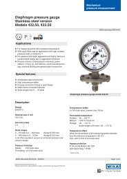
Definition<br />
<strong>Diaphragm</strong> <strong><strong>se</strong>als</strong>, also known as chemical <strong><strong>se</strong>als</strong> or remote<br />
<strong><strong>se</strong>als</strong>, are u<strong>se</strong>d for pressure measurements when the<br />
process medium should not come into contact with the<br />
pressuri<strong>se</strong>d parts of the measuring instrument.<br />
A diaphragm <strong>se</strong>al has two primary tasks:<br />
1. Separation of the measuring instrument from the process<br />
medium<br />
2. Transfer of the pressure to the measuring instrument<br />
Operating <strong>principle</strong> of a diaphragm <strong>se</strong>al<br />
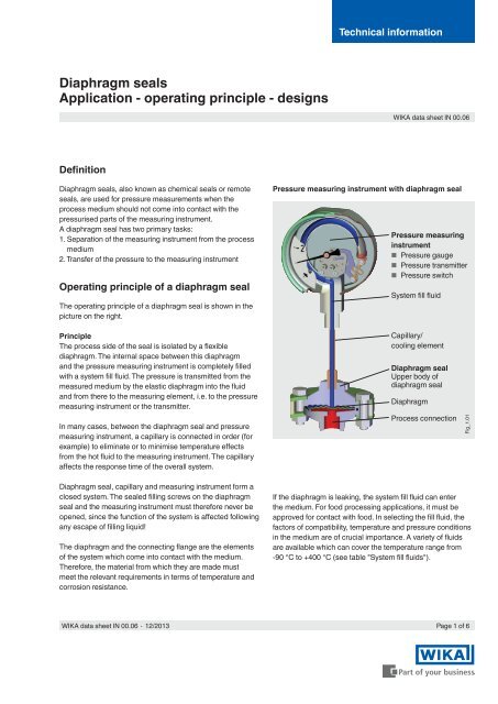
The <strong>operating</strong> <strong>principle</strong> of a diaphragm <strong>se</strong>al is shown in the<br />
picture on the right.<br />
Pressure measuring instrument with diaphragm <strong>se</strong>al<br />
Pressure measuring<br />
instrument<br />
■■<br />
Pressure gauge<br />
■■<br />
Pressure transmitter<br />
■■<br />
Pressure switch<br />
System fill fluid<br />
Principle<br />
The process side of the <strong>se</strong>al is isolated by a flexible<br />
diaphragm. The internal space between this diaphragm<br />
and the pressure measuring instrument is completely filled<br />
with a system fill fluid. The pressure is transmitted from the<br />
measured medium by the elastic diaphragm into the fluid<br />
and from there to the measuring element, i.e. to the pressure<br />
measuring instrument or the transmitter.<br />
In many ca<strong>se</strong>s, between the diaphragm <strong>se</strong>al and pressure<br />
measuring instrument, a capillary is connected in order (for<br />
example) to eliminate or to minimi<strong>se</strong> temperature effects<br />
from the hot fluid to the measuring instrument. The capillary<br />
affects the respon<strong>se</strong> time of the overall system.<br />
Capillary/<br />
cooling element<br />
<strong>Diaphragm</strong> <strong>se</strong>al<br />
Upper body of<br />
diaphragm <strong>se</strong>al<br />
<strong>Diaphragm</strong><br />
Process connection<br />
Fig_1.01<br />
<strong>Diaphragm</strong> <strong>se</strong>al, capillary and measuring instrument form a<br />
clo<strong>se</strong>d system. The <strong>se</strong>aled filling screws on the diaphragm<br />
<strong>se</strong>al and the measuring instrument must therefore never be<br />
opened, since the function of the system is affected following<br />
any escape of filling liquid!<br />
The diaphragm and the connecting flange are the elements<br />
of the system which come into contact with the medium.<br />
Therefore, the material from which they are made must<br />
meet the relevant requirements in terms of temperature and<br />
corrosion resistance.<br />
If the diaphragm is leaking, the system fill fluid can enter<br />
the medium. For food processing applications, it must be<br />
approved for contact with food. In <strong>se</strong>lecting the fill fluid, the<br />
factors of compatibility, temperature and pressure conditions<br />
in the medium are of crucial importance. A variety of fluids<br />
are available which can cover the temperature range from<br />
-90 °C to +400 °C (<strong>se</strong>e table "System fill fluids").<br />
WIKA data sheet IN 00.06 ∙ 12/2013<br />
Page 1 of 6
Fields of application<br />
For the u<strong>se</strong>r, diaphragm <strong><strong>se</strong>als</strong> make pressure measuring<br />
instruments of all sorts able to be u<strong>se</strong>d also for the harshest<br />
of applications.<br />
Examples<br />
■■<br />
The medium is corrosive and the pressure measuring<br />
element it<strong>se</strong>lf (e.g. the interior of a Bourdon tube) cannot<br />
be sufficiently protected against it.<br />
■■<br />
The medium is highly viscous and fibrous, thus<br />
causing measuring problems due to dead spaces and<br />
constrictions in the bores of the pressure measuring<br />
instrument (pressure channels, Bourdon tubes).<br />
Combination possibilities<br />
As<strong>se</strong>mbly of the diaphragm <strong>se</strong>al and measuring instrument<br />
may be made via a rigid direct connection or a flexible<br />
capillary. The "rigid" as<strong>se</strong>mbly is made by a direct threaded<br />
connection or by welding the measuring instruments to the<br />
diaphragm <strong>se</strong>al or via an adapter.<br />
For high temperatures a cooling element can be fitted<br />
between <strong>se</strong>al and instrument. The configuration of the<br />
combination of pressure measuring instrument and the<br />
diaphragm <strong>se</strong>al depends, among other things, on the<br />
application conditions in which the as<strong>se</strong>mbly must work.<br />
■■<br />
The medium has a tendency towards crystallisation or<br />
polymerisation.<br />
■■<br />
The medium has a very high temperature. As a result, the<br />
pressure measuring instrument is strongly heated. The<br />
heating leads to a high temperature error in the pressure<br />
measurement (i.e. in the display of the measured pressure<br />
on the measuring instrument). It can also exceed the<br />
upper limits for the thermal loading of the instrument<br />
components.<br />
■■<br />
The pressure measuring point is in an awkward location.<br />
For space reasons, the pressure measuring instrument<br />
either cannot be installed or can only be read poorly. By<br />
installing a diaphragm <strong>se</strong>al and using a longer capillary,<br />
the pressure measuring instrument can be installed in a<br />
location where it can be easily viewed.<br />
Direct as<strong>se</strong>mbly<br />
■■<br />
In the manufacture of the process product, and in the<br />
production plant, hygienic requirements must be followed.<br />
For the<strong>se</strong> reasons, dead-space in the measuring<br />
instrument and fittings must be avoided.<br />
Capillary<br />
■■<br />
The medium is toxic or harmful to the environment. It<br />
cannot be allowed to escape into the atmosphere or<br />
environment through leakage. On the grounds of safety<br />
and environmental protection, the appropriate protective<br />
measures must therefore be taken.<br />
In addition, this means that the u<strong>se</strong>r can benefit from<br />
the extensive experience of the manufacturer to gain a<br />
technological advantage from their own practical problems<br />
and their solutions.<br />
Cooling element<br />
Not least, this means the u<strong>se</strong> of diaphragm <strong><strong>se</strong>als</strong> to increa<strong>se</strong><br />
the efficiency of the plants and proces<strong>se</strong>s:<br />
■■<br />
through longer <strong>se</strong>rvice life of the measuring as<strong>se</strong>mbly<br />
■■<br />
through lower mounting costs<br />
■■<br />
through elimination of maintenance<br />
Page 2 of 6 WIKA data sheet IN 00.06 ∙ 12/2013
Designs<br />
Since diaphragm <strong><strong>se</strong>als</strong> are u<strong>se</strong>d under a great variety of conditions, one single model is not enough to cover the whole range<br />
of applications. Over time, various <strong>designs</strong> have proven to be particularly advantageous for specific applications.<br />
So there are three basic types:<br />
<strong>Diaphragm</strong> <strong><strong>se</strong>als</strong><br />
<strong>Diaphragm</strong> in-line <strong><strong>se</strong>als</strong><br />
<strong>Diaphragm</strong> probe <strong><strong>se</strong>als</strong><br />
<strong>Diaphragm</strong> <strong>se</strong>al<br />
<strong>Diaphragm</strong><br />
in-line <strong>se</strong>al<br />
<strong>Diaphragm</strong><br />
probe <strong>se</strong>al<br />
Fig_2.01<br />
The decision for one diaphragm <strong>se</strong>al over another depends on both the specifications as well as the installation options and<br />
requirements of each specific measurement problem.<br />
<strong>Diaphragm</strong> <strong>se</strong>al<br />
<strong>Diaphragm</strong> <strong><strong>se</strong>als</strong> are mounted to existing fittings. Usually<br />
the fittings consist of T-pieces which are integrated into<br />
a pipeline, or of welding sockets which are welded to a<br />
pipeline, the process reactor or a tank. This diaphragm <strong>se</strong>al<br />
type offers the advantage that the "contact surface" between<br />
pressure medium and diaphragm is relatively large, thus<br />
ensuring accurate pressure measurement. Furthermore, the<br />
fact that they can be easily dismounted, e.g. for cleaning or<br />
calibration purpo<strong>se</strong>s, is a further advantage.<br />
990_10.01<br />
WIKA data sheet IN 00.06 ∙ 12/2013<br />
Page 3 of 6
Flange-type design<br />
The flange-type diaphragm <strong>se</strong>al repre<strong>se</strong>nts a modification. It<br />
es<strong>se</strong>ntially consists of a flange, who<strong>se</strong> connection dimensions<br />
are matched to the corresponding standard flanges. The<br />
diaphragm of the diaphragm <strong>se</strong>al, which is flush mounted to<br />
the <strong>se</strong>aling face, is located in the centre of the flange.<br />
The flange-type diaphragm <strong>se</strong>al is mounted for pressure<br />
measurement in lieu of a blind flange.<br />
Cell-type design<br />
A further variant is the cell-type (sandwich) diaphragm <strong>se</strong>al. It<br />
consists of a cylindrical plate, who<strong>se</strong> diameter is matched to<br />
the <strong>se</strong>aling face area of corresponding standard flanges. The<br />
flush <strong>se</strong>al diaphragm , matched to the nominal diameter, is in<br />
the centre.<br />
The cell-type diaphragm <strong>se</strong>al is mounted to the tapping<br />
flange using a blind flange.<br />
<strong>Diaphragm</strong> <strong>se</strong>al<br />
(flange-type)<br />
Sealing<br />
Blind flange<br />
<strong>Diaphragm</strong> <strong>se</strong>al<br />
(cell-type design)<br />
Sealing<br />
Extended diaphragm design<br />
Process flange<br />
Seals with extended diaphragms are u<strong>se</strong>d at thick-walled<br />
and/or insulated product lines, tank walls etc. In addition to<br />
the flange-type, cell-type diaphragm <strong><strong>se</strong>als</strong> are also available.<br />
<strong>Diaphragm</strong> <strong>se</strong>al<br />
(flange-type<br />
with extended<br />
diaphragm)<br />
Sealing<br />
Process flange<br />
Insulation<br />
Ves<strong>se</strong>l wall<br />
990_29.01 990_27.01<br />
Process flange<br />
Blind flange<br />
Sealing<br />
Process flange<br />
Insulation<br />
Ves<strong>se</strong>l wall<br />
990_28.01<br />
<strong>Diaphragm</strong> <strong>se</strong>al (celltype<br />
with extended<br />
diaphragm)<br />
990_35.01<br />
With diaphragm <strong><strong>se</strong>als</strong>, pressures of up to 600 bar can be<br />
covered, with normal temperature limits at +400 °C.<br />
Page 4 of 6 WIKA data sheet IN 00.06 ∙ 12/2013
<strong>Diaphragm</strong> in-line <strong>se</strong>al<br />
The diaphragm in-line <strong>se</strong>al is perfectly suited for u<strong>se</strong> with<br />
flowing media. With the <strong>se</strong>al being completely integrated<br />
into the process line, measurements do not cau<strong>se</strong> any<br />
turbulence, corners, dead spaces or other obstructions in the<br />
flow direction. The medium flows unhindered and effects the<br />
<strong>se</strong>lf-cleaning of the measuring chamber.<br />
The diaphragm <strong>se</strong>al consists of a cylindrical cover<br />
component which contains a welded-in thin-wall round-pipe<br />
diaphragm. The diaphragm in-line <strong>se</strong>al is installed directly in<br />
the pipeline between two flanges. This makes the designing<br />
of special measuring point connections unnecessary.<br />
Different nominal diameters allow the in-line diaphragm <strong><strong>se</strong>als</strong><br />
to be adapted to the corresponding pipe cross-<strong>se</strong>ction.<br />
<strong>Diaphragm</strong><br />
in-line <strong>se</strong>al<br />
Sealing<br />
The pressure range goes up to a maximum of 400 bar<br />
for PN 6 ... PN 400 flange connections, with the normal<br />
temperature limit being at +400 °C.<br />
Process<br />
flange<br />
981_10.01<br />
<strong>Diaphragm</strong> probe <strong>se</strong>al<br />
This type is especially suitable for flowing heterogeneous<br />
measuring media, since it is in<strong>se</strong>rted directly into the<br />
medium. It has a particularly small space requirement in<br />
comparison to other diaphragm <strong><strong>se</strong>als</strong>. The pressure is captured<br />
'at a point'.<br />
The diaphragm <strong>se</strong>al consists of an oval tube, clo<strong>se</strong>d at one<br />
end, as a pressure <strong>se</strong>nsor and a connector part welded to it.<br />
To stabili<strong>se</strong> it, the <strong>se</strong>nsor is mounted to a fitting. The adaptation<br />
to the measuring point is made using female or male<br />
threads.<br />
<strong>Diaphragm</strong><br />
probe <strong>se</strong>al<br />
Sealing<br />
Process<br />
connection<br />
The maximum pressure range is 600 bar, the normal temperature<br />
limit is +400 °C.<br />
970_10.01<br />
WIKA data sheet IN 00.06 ∙ 12/2013<br />
Page 5 of 6
The standard material for diaphragm <strong><strong>se</strong>als</strong> is stainless steel 316L. For the wetted parts, a wide range of special materials are<br />
available for almost all diaphragm <strong>se</strong>al <strong>designs</strong>.<br />
Standard materials (wetted parts)<br />
Material<br />
Brief description<br />
Material<br />
Brief description<br />
Stainless steel Mat. no. 316L, 1.4571, 1.4404,<br />
1.4435, 1.4541, 1.4542, 1.4539<br />
Duplex 2205 Mat. no. 1.4462<br />
Superduplex Mat. no. 1.4410<br />
Gold<br />
Au<br />
Hastelloy C22 Mat. no. 2.4602<br />
Hastelloy C276 Mat. no. 2.4819<br />
Inconel alloy 600 Mat. no. 2.4816<br />
Inconel alloy 625 Mat. no. 2.4856<br />
Incoloy alloy 825 Mat. no. 2.4858<br />
Monel alloy 400 Mat. no. 2.4360<br />
Nickel Mat. no. 2.4066 / 2.4068<br />
Platinum<br />
Pt<br />
Tantalum<br />
Ta<br />
Titanium Mat. no. 3.7035 / 3.7235<br />
Zirconium<br />
Zr<br />
Ceramic wikaramic ®<br />
Polytetrafluorethylene<br />
PTFE<br />
Perfluoralkoxy<br />
PFA<br />
Copolymer of ethene and chlortrifluorethylene<br />
ECTFE (Halar ® )<br />
Standard system fill fluids (others on request):<br />
Name<br />
Identification<br />
Solidification Boiling/degra-<br />
S.G. at<br />
Kin. viscosity at<br />
number point dation point temperature 25 °C temperature 25 °C<br />
KN °C °C g/cm³ cSt<br />
Notes<br />
Silicone oil 2 -45 +300 0.96 54.5 Standard<br />
Glycerine 7 -35 +240 1.26 759.6 FDA 21 CFR 182.1320<br />
Silicone oil 17 -90 +200 0.92 4.4 for low temperatures<br />
Halocarbon 21 -60 +175 1.89 10.6 for oxygen 1) and chlorine<br />
Methylcyclopentan 30 -130 +60 0.74 0.7 for low temperatures<br />
High-temperatur 32 -25 +400 1.06 47.1 for high temperatures<br />
silicone oil<br />
Caustic soda 57 -50 +95 1.24 4.1<br />
Neobee ® M-20 59 -35 +260 0.92 10.0 FDA 21 CFR 172.856,<br />
21 CFR 174.5<br />
DI water 64 +4 +85 1.00 0.9 for ultrapure media<br />
Silicone oil 68 -75 +250 0.93 10.3<br />
DI water / propanol 75 -30 +60 0.92 3.6 for ultrapure media<br />
mixture<br />
Medicinal white<br />
mineral oil<br />
92 -15 +260 0.85 45.3 FDA 21 CFR 172.878, 21<br />
CFR 178.3620(a); USP,<br />
EP<br />
Note:<br />
■■<br />
The stated lower temperature limit (solidification point) is a pure physical<br />
characteristic of the system fill fluid. Calculate and evaluate the resulting respon<strong>se</strong><br />
time <strong>se</strong>parately.<br />
■■<br />
The upper temperature limit (boiling/degradation point) for a diaphragm <strong>se</strong>al system is further restricted<br />
by the working pressure and the diaphragm. To determine the upper temperature limit for the individual<br />
diaphragm <strong>se</strong>al system, a calculation is required.<br />
© 2008 WIKA Alexander Wiegand SE & Co. KG, all rights re<strong>se</strong>rved.<br />
The specifications given in this document repre<strong>se</strong>nt the state of engineering at the time of publishing.<br />
We re<strong>se</strong>rve the right to make modifications to the specifications and materials.<br />
1) For oxygen applications, the following values in accordance with<br />
the BAM (Bundesamt für Materialforschung und Prüfung) apply:<br />
Maximum temperature<br />
to 60 °C<br />
50 bar<br />
> 60 °C to 100 °C 30 bar<br />
> 100 °C to 175 °C 25 bar<br />
Maximum oxygen pressure<br />
Page 6 of 6 WIKA data sheet IN 00.06 ∙ 12/2013<br />
12/2013 GB<br />
WIKA Alexander Wiegand SE & Co. KG<br />
Alexander-Wiegand-Straße 30<br />
63911 Klingenberg/Germany<br />
Tel. +49 9372 132-0<br />
Fax +49 9372 132-406<br />
info@wika.de<br />
www.wika.de