Pump Guardian - Hansen Technologies
Pump Guardian - Hansen Technologies
Pump Guardian - Hansen Technologies

Create successful ePaper yourself
Turn your PDF publications into a flip-book with our unique Google optimized e-Paper software.
Bulletin HP519b<br />
JAN 2011<br />
Specifications, Applications,<br />
Service Instructions & Parts<br />
PUMP GUARDIAN<br />
PUMP CONTROLLER<br />
for Refrigerant Recirculator<br />
Packages, Accumulators,<br />
Receivers and Intercoolers<br />
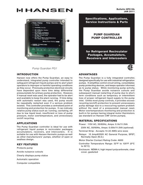
<strong>Pump</strong> <strong>Guardian</strong> PG1<br />
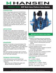
INTRODUCTION<br />
<strong>Hansen</strong> now offers the <strong>Pump</strong> <strong>Guardian</strong>, an easy to<br />
understand, integrated pump controller intended to<br />
safeguard refrigerant liquid pumps and to alert plant<br />
operators to improper or harmful operating conditions<br />
as they occur. Previously protective electrical circuits<br />
have depended upon mere time delay differential<br />
pressurestats for primary pump protection. However,<br />
if manual reset was used, the operator had to be alert<br />
and available to keep the plant running. If time delay<br />
with automatic restart was used, the pump would<br />
be repeatedly restarted even if a serious problem<br />
existed. This controller provides a centralized point of<br />
monitoring and protection for pumps. It can indicate<br />
relative pump status such as: running, cavitating, off<br />
due to low liquid level, insufficient or loss of pump<br />
pressure, motor overtemperature, and unnecessary<br />
on/off recycling.<br />
APPLICATIONS<br />
The <strong>Pump</strong> <strong>Guardian</strong> controller is ideal for use with<br />
refrigerant liquid pumps in recirculator packages,<br />
accumulators, receivers, and intercoolers. It is<br />
suitable for use with <strong>Hansen</strong> Hermetic pumps as well<br />
as other manufacturers’ pumps, whether of open or<br />
sealless design.<br />
KEY FEATURES<br />
Protects pump<br />
Avoids nuisance cutouts<br />
Clearly displays pump status<br />
Automatic operation<br />
Computer compatible<br />
ADVANTAGES<br />
The <strong>Pump</strong> <strong>Guardian</strong> is a fully integrated controller,<br />
designed specifically for use with industrial refrigeration<br />
pumps. It simplifies control circuit wiring, consolidates<br />
pump protecting devices, and keeps operator informed<br />
as to pump status. While monitoring pump activity,<br />
the <strong>Pump</strong> <strong>Guardian</strong> avoids nuisance cutouts and<br />
subsequent manual restarting of pump due to shortterm<br />
conditions such as temporary or intermittent<br />
loss of proper refrigerant liquid supply to the pump<br />
inlet. Unlike most pump controls, it provides excessrecycling<br />
(on/off) protection to prevent unnecessary<br />
pump damage due to a reoccurring system problem<br />
without the need of a pressurestat manual reset.<br />
Motor overtemperature monitoring and protection is<br />
built-in for pumps having integral motor thermistors<br />
(as standard on <strong>Hansen</strong> CNF series pumps).<br />
MATERIAL SPECIFICATIONS<br />
Power: 115V AC, 50/60Hz, Amps: 0.1A/11.5VA<br />
230V AC, 50/60Hz, Amps: 0.05A/11.5VA (optional)<br />
Terminal Strip: Accepts 14-22 AWG wire sizes<br />
Relays: 10 Amp@250V AC General Purpose, SPST,<br />
Normally Open (N.O.)<br />
Motor Starter Contact Rating Code: A600<br />
Controller Temperature Range: 32ºF to 120ºF (0ºC<br />
to 50°C)<br />
Enclosure: NEMA 4, high impact polycarbonate, clear<br />
cover, gasketed
INSTALLATION<br />
Mount controller, which has a watertight enclosure,<br />
at “eye level” in an accessible indoor location away<br />
from potential impact or vibration. Use four screws<br />
(0.5” or longer) to fasten enclosure. See installation<br />
dimensions on page 4. Leave adequate space for<br />
electrical connections. A ½” conduit knockout (0.88”<br />
hole) is provided. Any additional conduit entrances<br />
must be located at the bottom of the enclosure to<br />
avoid possible dust and water damage to electronics.<br />
Use of rigid or flexible conduit constructed from<br />
metallic or non-metallic material is acceptable. When<br />
using rigid conduit, the conduit hub must be preassembled<br />
to the rigid conduit before installation on<br />
the enclosure. Conduit fitting should be of a watertight<br />
seal design where applicable.<br />
Except during installation and possible servicing, the<br />
clear cover of the controller should remain on the<br />
enclosure and screwed tight. This will help prevent<br />
possible damage to controller by inadvertent water<br />
spray, physical damage or corrosive chemicals in the<br />
atmosphere.<br />
INSTALLATION DIMENSIONS<br />
6.89"<br />
(175 mm)<br />
6.18"<br />
(157 mm)<br />
0.34"<br />
(9 mm)<br />
HP519b<br />
JAN 2011<br />
0.34"<br />
(9 mm)<br />
WIRE ONLY FROM<br />
BOTTOM OF<br />
ENCLOSURE<br />
3.94"<br />
(100 mm)<br />
1.28"<br />
(33 mm)<br />
3.45"<br />
(88 mm)<br />
6.89"<br />
(175 mm)<br />
6.18"<br />
(157 mm)<br />
<strong>Pump</strong> Status<br />
Running<br />
Cavitating(Low p)<br />
Off 3 Minutes: Caution<br />
(Auto Restart)<br />
Off: Excess Cavitations<br />
(Alarm) (Manual Reset Button)<br />
Off Due to Low Level<br />
(Auto Restart)<br />
Off Due to Motor Overtemperature<br />
(Motor Option) (Auto Restart)<br />
Manual Reset Button<br />
HANSEN TECHNOLOGIES<br />
CORPORATION<br />
FRONT VIEW<br />
CLEAR COVER<br />
BOTTOM VIEW<br />
2.00"<br />
(51 mm)<br />
MANUAL<br />
RESET<br />
BUTTON<br />
0.19" (5 mm) MOUNTING<br />
HOLES LOCATED<br />
BEHIND COVER SCREWS<br />
COVER SCREWS<br />
(TYPICAL)<br />
1/2" CONDUIT KNOCK-OUT<br />
ENCLOSURE BASE<br />
2<br />
PUMP STATUS<br />
The <strong>Pump</strong> Status Lights visually indicate to the<br />
operator the pump activity. These bright LED lights<br />
are located on the front of controller and, when<br />
illuminated, can be seen from afar. Their functional<br />
meaning is described below:<br />
RUNNING<br />
This status light (green) is on anytime the pump is<br />
running and the motor starter relay (terminals 3 & 4)<br />
is closed. When pumping conditions are normal, this<br />
will be the only status light on.<br />
CAVITATING (OR LOW ΔP)<br />
If pump begins to cavitate or loses pumping pressure<br />
due to an absence of liquid at pump inlet and the<br />
pressure difference across pump drops below a preset<br />
value (10 psid), the differential pressurestat switch<br />
contacts open and the status light (amber) goes on.<br />
OFF 3 MINUTES: CAUTION<br />
This status light (red) indicates that the pump was<br />
CAVITATING continuously for 30 seconds and is now<br />
off (motor starter relay open) for 3 minutes. Afterwards,<br />
if conditions are normal, the pump will automatically<br />
restart (motor starter relay closed).<br />
OFF: EXCESS CAVITATIONS<br />
If controller turns pump off and on 6 times within an<br />
hour due to cavitation, this status light (red) goes on,<br />
the alarm relay (terminals 5 & 6) closes and pump will<br />
remain off (motor starter relay open). Alternately, if<br />
accumulated CAVITATING time within an hour reaches 6<br />
minutes, the same result occurs except this status light<br />
will blink. If a system contains no liquid refrigerant,<br />
as for a noncommissioned new plant, the pump would<br />
be stopped (thereby protected from dry running) by<br />
this excess cavitations feature. In either case, the<br />
pump can be restarted (motor starter relay closed)<br />
by pushing the Manual Reset Button on the side of<br />
the controller. Whenever a pump is shutdown due<br />
to “excess cavitations”, it is important to determine<br />
what caused the condition and correct it promptly to<br />
avoid future incidents.<br />
OFF DUE TO LOW LEVEL<br />
If refrigerant liquid inside vessel drops below the low<br />
level float switch or other low level control, this status<br />
light (red) goes on and the pump turns off (motor<br />
starter relay open). If the level does not recover within<br />
a 1/2 hour, the alarm relay will close. When the liquid<br />
level rises above the low level point, including any<br />
differential, this status light goes off and the pump<br />
automatically restarts (motor starter relay closed).<br />
OFF DUE TO MOTOR OVERTEMPERATURE<br />
<strong>Hansen</strong> CNF series pumps have integral motor<br />
overtemperature thermistors inside the motor windings.<br />
When these thermistors are properly connected to<br />
controller (terminals 11 & 12), motor temperature can<br />
be accurately sensed. If motor becomes too hot, this<br />
status light (red) goes on and pump is turned off (motor<br />
starter relay open). If the motor does not cool down<br />
within a 1/2 hour, the alarm relay will close. When<br />
the temperature lowers sufficiently, the status light<br />
goes off and the pump automatically restarts (motor<br />
starter relay closed). This built-in feature replaces<br />
the need for the INT-69 motor overtemperature control<br />
device.
WIRING DIAGRAM<br />
This wiring diagram is for illustration purposes only and does not show all controls and safety devices. Final<br />
control wiring is the responsibility of the system designer.<br />
PUMP STATUS<br />
LIGHTS (TYPICAL)<br />
PUMP STATUS<br />
Running<br />
Cavitating (Low p)<br />
Off 3 Minutes: Caution<br />
(Auto Restart)<br />
Off: Excess Cavitations<br />
(Alarm) (Manual Reset Button)<br />
Off Due to Low Level<br />
(Auto Restart)<br />
Off Due to Motor Overtemperature<br />
(Motor Option) (Auto Restart)<br />
MANUAL RESET<br />
BUTTON<br />
REPLACEABLE<br />
250 mA FUSE<br />
(P/N 61-0421)<br />
FUSE<br />
Manual Reset Button<br />
HANSEN TECHNOLOGIES<br />
CORPORATION<br />
COMMUNICATION PORT<br />
TERMINAL STRIP<br />
GROUND SCREW<br />
L<br />
DIFFERENTIAL<br />
PRESSURE STAT<br />
(61-0418)<br />
N<br />
INSTALL JUMPER<br />
IF NO THERMISTORS<br />
FIELD INSTALLED<br />
5 AMP FUSE<br />
VARI-LEVEL (OR<br />
FLOAT SWITCH)<br />
ALARM<br />
THERMISTORS IN<br />
PUMP MOTOR<br />
MOTOR<br />
STARTER<br />
COIL<br />
PUMP ON-OFF SWITCH<br />
LINE VOLTAGE<br />
*Note: A non-time delay, non-manual restart differential pressurestat (such as 61-0418) is required. However, an existing differential<br />
pressurestat having a time delay relay can be field retrofitted to suit, see <strong>Hansen</strong> Sales Drawing #6100-73.<br />
ELECTRICAL<br />
The motor starter and alarm relays (terminals 3 & 4 and<br />
5 & 6) are 10 AMP, SPST, Normally Open, dry contact<br />
relays. (“Dry contact” refers to a device in which an<br />
electrical connection is made by a pair of metallic<br />
contacts.) Circuits for these relays can be powered<br />
by line voltage. Conversely, the input terminals (7<br />
thru 12) should never have line voltage applied to<br />
them. The differential pressurestat input (terminals<br />
7 & 8) and low level input (terminals 9 & 10) require<br />
a dry contact, Normally Open switch or relay. The<br />
motor temperature input (terminals 11 & 12) normally<br />
requires a motor thermistor circuit. The controller will<br />
indicate pump motor overtemperature if the resistance<br />
at these terminals becomes greater than 4K ohms. If<br />
the pump motor does not have thermistors (such as<br />
<strong>Hansen</strong> CAM series pumps) or if non-<strong>Hansen</strong> pump<br />
thermistors are not compatible with this circuit, simply<br />
use a wire jumper across terminals 11 & 12 to bypass<br />
this feature.<br />
3<br />
Electrical power should be connected in series from<br />
the pump on-off switch to the controller. This is so<br />
the controller is powered only during desired pump<br />
run situations; otherwise erroneous alarms may occur.<br />
Install a 5 amp fuse to protect electrical circuits<br />
connected to the controller; see wiring diagram above.<br />
Before connecting electrical power to controller<br />
(terminals 1 & 2), check voltage on nameplate and<br />
power at the electrical leads to be sure they are the<br />
same. Supply voltage must be within +10% or -15%<br />
of nameplate voltage. A small, replaceable 250 mA<br />
fuse is located on circuit board to protect controller<br />
electronics; fuse p/n 61-0421.<br />
HP519b<br />
JAN 2011
HANSEN TECHNOLOGIES Vari-Level<br />
CORPORATION<br />
HANSEN TECHNOLOGIES<br />
CORPORATION<br />
1 2 3 4 5 6 7 8 9 10 11 12<br />
MOTOR OPTIONAL<br />
P-STAT<br />
STARTER ALARM<br />
P<br />
115V<br />
AC<br />
50/60 Hz<br />
LOW<br />
LEVEL<br />
MOTOR<br />
TEMP<br />
DIFFERENTIAL PRESSURESTAT<br />
A non-time delay, non-manual restart differential<br />
pressurestat (such as 61-0418) is required. This<br />
provides a dependable and economical pressure<br />
indicator for liquid refrigerant pumps. It enables the<br />
controller to detect a loss of pressure thus preventing<br />
the pump from running dry. The factory differential<br />
pressure setting is 10 psid.<br />
Pressure is sensed across the inlet and outlet of the<br />
pump. <strong>Pump</strong> outlet pressure should be sensed at<br />
the ¼” NPT fitting (discharge port adapter) located<br />
just below pump discharge flange. For non-<strong>Hansen</strong><br />
pumps, use a fitting near pump discharge to sense<br />
outlet pressure. <strong>Pump</strong> inlet pressure should be sensed<br />
near the pump inlet on top of the suction line.<br />
MANUAL RESET BUTTON<br />
The Manual Reset Button is located on the right side<br />
of the controller enclosure. If an OFF: EXCESSIVE<br />
CAVITATIONS status occurs, this button must be<br />
momentarily pushed to restart pump (motor starter<br />
relay closed). Using the Manual Reset Button also<br />
resets the count of pump shutdowns (6 count) to<br />
zero; see OFF: EXCESSIVE CAVITATIONS in <strong>Pump</strong><br />
Status section.<br />
COMMUNICATIONS<br />
The <strong>Pump</strong> <strong>Guardian</strong> has a computer compatible<br />
RS232 serial communications port. This port, in<br />
conjunction with a computer and communication<br />
software, enables access to additional information<br />
available from the microprocessor inside of the<br />
controller. This information includes: total number<br />
of cavitation shutdowns, total pump run time, total<br />
number of level and temperature shutdowns, input<br />
device status and more. Contact factory for the RS232<br />
serial communications port specifications and field<br />
installation recommendations.<br />
CAUTION<br />
The <strong>Hansen</strong> <strong>Pump</strong> <strong>Guardian</strong> pump controller is only for<br />
use in refrigeration systems. These instructions and<br />
related safety precautions must be read completely<br />
and understood before selecting or using this<br />
controller. Only knowledgeable, trained refrigeration<br />
mechanics should install or operate this controller.<br />
Stated electrical and temperature ranges should not<br />
be exceeded. Any wiring and application diagrams<br />
provided are for illustration purposes only. The<br />
system designer has the final responsibility as to<br />
how this pump controller is connected and operated.<br />
The designer is also responsible for systems and<br />
components being designed to prevent abnormal<br />
pressures or velocity impact pressure surges. Where<br />
critical temperatures or products are involved, backup<br />
temperature controls or alarms are required. See<br />
also Safety Precautions in current List Price Bulletin<br />
and Safety Precautions Sheet supplied with product.<br />
Escaping refrigerant might cause personal injury,<br />
particularly to the eyes and lungs.<br />
HP519b<br />
JAN 2011<br />
4<br />
TYPICAL APPLICATION<br />
VESSEL<br />
PUMP SUCTION LINE<br />
TYPICAL SPECIFICATIONS<br />
“<strong>Pump</strong> controllers shall provide a means of protection<br />
against cavitation, dry running, low liquid level,<br />
excessive on-off recycling and motor overtemperature,<br />
and have manual reset capability, a communications<br />
port for computer monitoring, and a visual display<br />
of pump status, such as the <strong>Pump</strong> <strong>Guardian</strong> as<br />
manufactured by <strong>Hansen</strong> <strong>Technologies</strong> Corporation<br />
or approved equal.”<br />
WARRANTY<br />
<strong>Pump</strong> <strong>Guardian</strong> pump controllers are guaranteed<br />
against defective materials or workmanship for 90<br />
days F.O.B. our plant. No consequential damages or<br />
field labor is included.<br />
ORDERING INFORMATION<br />
CAT. NO.<br />
PG1<br />
LEVEL<br />
COLUMN<br />
ALTERNATE<br />
LOW LEVEL<br />
FLOAT SWITCH<br />
DIFFERENTIAL<br />
PRESSURESTAT<br />
(NO DELAY, NO RESET)<br />
PUMP<br />
VARI-LEVEL®<br />
LEVEL CONTROLLER<br />
<strong>Pump</strong> Status<br />
PUMP DISCHARGE LINE<br />
Manual Reset Button<br />
DESCRIPTION<br />
PUMP GUARDIAN <strong>Pump</strong> Controller with<br />
Watertight Enclosure<br />
Specify Catalog Number PG1 and Voltage (115V AC<br />
or 230V AC; 50/60Hz).<br />
The <strong>Pump</strong> <strong>Guardian</strong> controller requires a differential<br />
pressurestat having no time delay and no manual reset.<br />
If needed, please also order differential pressurestat<br />
p/n 61-0418 when ordering controller.<br />
<strong>Hansen</strong> <strong>Technologies</strong> Corporation<br />
400 Quadrangle Dr, Suite F<br />
Bolingbrook, Illinois 60440 USA<br />
Tel: 630.325.1565 Fax: 630.325.1572 Toll: 800.426.7368<br />
Email: sales@hantech.com Web: www.hantech.com<br />
USA ∙ Asia ∙ Europe ∙ India ∙ Latin America ∙ Middle East<br />
© 2011 <strong>Hansen</strong> <strong>Technologies</strong> Corporation<br />
+65<br />
FROM MOTOR<br />
THERMISTORS<br />
REMOTE<br />
ALARM<br />
MOTOR<br />
STARTER