Welcome to Practical Components - Standard ICs
Welcome to Practical Components - Standard ICs
Welcome to Practical Components - Standard ICs

Create successful ePaper yourself
Turn your PDF publications into a flip-book with our unique Google optimized e-Paper software.
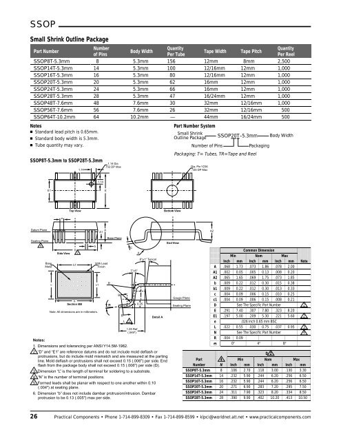
SSOP<br />
Small Shrink Outline Package<br />
Part Number<br />
Number<br />
Quantity<br />
Quantity<br />
Body Width<br />
Tape Width Tape Pitch<br />
of Pins<br />
Per Tube<br />
Per Reel<br />
SSOP8T-5.3mm 8 5.3mm 156 12mm 8mm 2,500<br />
SSOP14T-5.3mm 14 5.3mm 100 12/16mm 12mm 1,000<br />
SSOP16T-5.3mm 16 5.3mm 80 12/16mm 12mm 1,000<br />
SSOP20T-5.3mm 20 5.3mm 62 16mm 12mm 1,000<br />
SSOP24T-5.3mm 24 5.3mm 66 16mm 12mm 1,000<br />
SSOP28T-5.3mm 28 5.3mm 47 16/24mm 12mm 1,000<br />
SSOP48T-7.6mm 48 7.6mm 30 32mm 12/16mm 1,000<br />
SSOP56T-7.6mm 56 7.6mm 26 32mm 12/16mm 500<br />
SSOP64T-10.2mm 64 10.2mm — 44mm 16/24mm 500<br />
Notes<br />
<strong>Standard</strong> lead pitch is 0.65mm.<br />
<strong>Standard</strong> body width is 5.3mm.<br />
Tube quantity may vary.<br />
SSOP8T-5.3mm <strong>to</strong> SSOP28T-5.3mm<br />
1.14<br />
1.14 Dia<br />
.152 DP Max<br />
Part Number System<br />
Small Shrink<br />
Outline Package SSOP20T–5.3mm Body Width<br />
Number of Pins<br />
Packaging<br />
Packaging: T= Tubes, TR=Tape and Reel<br />
Dia. Pin Y236<br />
.125 DP Max<br />
1.14<br />
E1<br />
E<br />
Top View<br />
Bot<strong>to</strong>m View<br />
e<br />
Datum Plane<br />
A1 A<br />
A2<br />
Seating Plane<br />
5<br />
Base<br />
Metal<br />
c<br />
Side View<br />
D<br />
2<br />
b1<br />
b<br />
Section BB<br />
Note: All dimensions are in millimeters.<br />
b<br />
With Lead<br />
Finish<br />
c1<br />
Base Plane<br />
Notes:<br />
1. Dimensions and <strong>to</strong>lerancing per ANSI Y14.5M-1982.<br />
2. “D” and “E1” are reference datums and do not include mold deflash or<br />
protrusions, but do include mold mismatch and are measured at the parting<br />
line. Mold deflash or protrusions shall not exceed 0.15 (.006") per side. End<br />
flash from the package body shall not exceed 0.15 (.006") per side (D).<br />
3. Dimension “L” is the length of terminal for soldering <strong>to</strong> a substrate.<br />
4. “N” is the number of terminal positions.<br />
5. Formed leads shall be planar with respect <strong>to</strong> one another within 0.10<br />
(.004") at seating plane.<br />
6. Dimension “b” does not include dambar protrusion/intrusion. Dambar<br />
protrusion <strong>to</strong> be 0.13 (.005") max per side.<br />
R<br />
D<br />
B<br />
B<br />
L<br />
3<br />
C<br />
7°±5°<br />
1.25 Ref<br />
(.049")<br />
A<br />
8°±1° Typical<br />
0.25<br />
Detail A<br />
End View<br />
Gauge Plane<br />
Seating Plane<br />
Common Dimension<br />
Min Nom Max<br />
Inch mm Inch mm Inch mm Note<br />
A .068 1.73 .073 1.86 .078 2.00<br />
A1 .002 0.05 .005 0.13 .008 0.20<br />
A2 .065 1.65 .069 1.75 .073 1.85<br />
b .009 0.22 .012 0.30 .015 0.38<br />
b1 .009 0.22 .012 0.30 .013 0.33<br />
c .004 0.09 .006 0.15 .010 0.25<br />
c1 .004 0.09 .006 0.15 .008 0.21<br />
D See The Specific Part Number 2<br />
E .291 7.40 .307 7.80 .323 8.20<br />
E1 .197 5.00 .209 5.30 .221 5.60 2<br />
e<br />
.026 Inch 0.65 mm BSC<br />
L .022 0.55 .030 0.75 .037 0.95 3<br />
N See The Specific Part Number 4<br />
R .004 0.09<br />
0° 4° 8°<br />
D<br />
D 2<br />
Part 4 Min Nom Max<br />
Number N Inch mm Inch mm Inch mm<br />
SSOP8T-5.3mm 8 .106 2.70 .118 3.00 .130 3.30<br />
SSOP14T-5.3mm 14 .232 5.90 .244 6.20 .256 6.50<br />
SSOP16T-5.3mm 16 .232 5.90 .244 6.20 .256 6.50<br />
SSOP20T-5.3mm 20 .271 6.90 .283 7.20 .295 7.50<br />
SSOP24T-5.3mm 24 .311 7.90 .323 8.20 .334 8.50<br />
SSOP28T-5.3mm 28 .390 9.90 .402 10.20 .413 10.50<br />
26 <strong>Practical</strong> <strong>Components</strong> • Phone 1-714-899-8309 • Fax 1-714-899-8599 • klpci@worldnet.att.net • www.practicalcomponents.com