198934 Roof Stairs INSTALLATION INSTRUCTIONS.pdf - Westeel
198934 Roof Stairs INSTALLATION INSTRUCTIONS.pdf - Westeel
198934 Roof Stairs INSTALLATION INSTRUCTIONS.pdf - Westeel

You also want an ePaper? Increase the reach of your titles
YUMPU automatically turns print PDFs into web optimized ePapers that Google loves.
Optional <strong>Roof</strong> Stair Block-Off Assembly<br />
The “<strong>Roof</strong> Stair Block-off Package” is an option that mates with a roof stair package when the<br />
roof stairs is not used in combination with a <strong>Westeel</strong> ladder package. Such would be the case if<br />
the roof stair was being accessed from an overhead conveyor, and there was no wall ladder.<br />
The “Stair Block-off Package” is intended to provide a barrier at the lower end of the roof stair to<br />
prevent somebody from stepping off into space.<br />
Some of the necessary parts are supplied with the roof stair package that forms the “Inspection<br />
Hatch Cage Assembly” (see applicable section). The balance of the parts are supplied as part<br />
of the “<strong>Roof</strong> Stair Block-off Package”.<br />
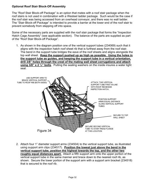
1. As shown in the diagram position one of the vertical support tubes (234069) such that it<br />
aligns with the inspection hatch roof sheet rib that is furthest away from the roof stair.<br />
The bend in the support tube bridges the eave of the roof sheets and aligns alongside the<br />
top wall sheet. Keep the support pushed up as high as possible. Using the holes in<br />
the support tube as guides, and keeping the support tube in a vertical orientation,<br />
drill 3/8” holes through the crest of the mating wall sheet corrugations and attach<br />
using 3/8” x 2 ½” bolts. Putting the sealing washers on the inside insures a water tight<br />
seal.<br />
USE SUPPORT ARM TO<br />
BRACE VERTICAL SUPPORT<br />
TUBE TO ROOF RIB (BOTH SIDES)<br />
ATTACH THIS VERTICAL<br />
SUPPORT TUBE FIRST IN-LINE<br />
WITH ROOF RIB BESIDE<br />
INSPECTION HATCH.<br />
POSITION SUPPORT<br />
ARMS EQUAL DISTANCE<br />
ALONG VERTICAL SUPPORT<br />
TUBES<br />
SECURE TO TOP<br />
WALL SHEET<br />
Figure 34<br />
SECURE SECOND VERTICAL<br />
TUBE TO STAIR TREAD FLANGE<br />
AT THIS LOCATION<br />
2. Attach four 1” diameter support arms (234504) to the vertical support tube, as illustrated<br />
using support arm clips (234517). Position the lowest just above the bend in the<br />
vertical support tube, position the highest towards the top, and the other two<br />
roughly equal distances apart. Attach a fifth support arm onto the upper portion of the<br />
vertical support tube in the same manner and brace down to the nearest roof rib, as<br />
shown. Secure the lower portion of the support arm with a support arm bracket (234518)<br />
that is secured to the roof rib.<br />
Page 32