INSTALLATION INSTRUCTIONS Râ410A Ductless Split System Air ...
INSTALLATION INSTRUCTIONS Râ410A Ductless Split System Air ...
INSTALLATION INSTRUCTIONS Râ410A Ductless Split System Air ...

Create successful ePaper yourself
Turn your PDF publications into a flip-book with our unique Google optimized e-Paper software.
<strong>INSTALLATION</strong> <strong>INSTRUCTIONS</strong><br />
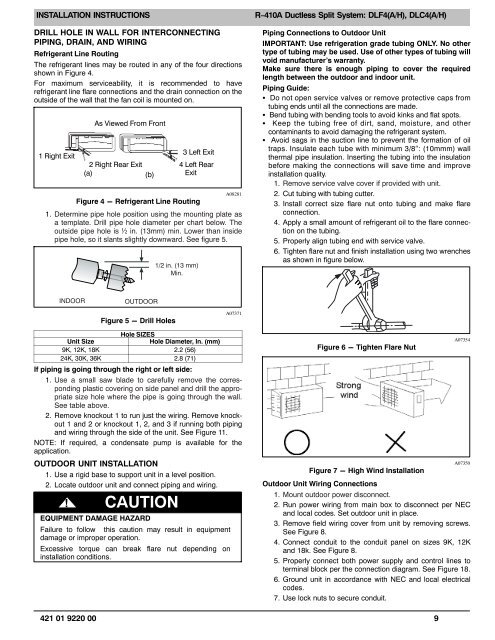
DRILL HOLE IN WALL FOR INTERCONNECTING<br />
PIPING, DRAIN, AND WIRING<br />
Refrigerant Line Routing<br />
The refrigerant lines may be routed in any of the four directions<br />
shown in Figure 4.<br />
For maximum serviceability, it is recommended to have<br />
refrigerant line flare connections and the drain connection on the<br />
outside of the wall that the fan coil is mounted on.<br />
1 Right Exit<br />
As Viewed From Front<br />
2 Right Rear Exit<br />
(a)<br />
(b)<br />
3 Left Exit<br />
4 Left Rear<br />
Exit<br />
A08281<br />
Figure 4 - Refrigerant Line Routing<br />
1. Determine pipe hole position using the mounting plate as<br />
a template. Drill pipe hole diameter per chart below. The<br />
outside pipe hole is ½ in. (13mm) min. Lower than inside<br />
pipe hole, so it slants slightly downward. See figure 5.<br />
1/2 in. (13 mm)<br />
Min.<br />
R−410A <strong>Ductless</strong> <strong>Split</strong> <strong>System</strong>: DLF4(A/H), DLC4(A/H)<br />
Piping Connections to Outdoor Unit<br />
IMPORTANT: Use refrigeration grade tubing ONLY. No other<br />
type of tubing may be used. Use of other types of tubing will<br />
void manufacturer’s warranty.<br />
Make sure there is enough piping to cover the required<br />
length between the outdoor and indoor unit.<br />
Piping Guide:<br />
Do not open service valves or remove protective caps from<br />
tubing ends until all the connections are made.<br />
Bend tubing with bending tools to avoid kinks and flat spots.<br />
Keep the tubing free of dirt, sand, moisture, and other<br />
contaminants to avoid damaging the refrigerant system.<br />
Avoid sags in the suction line to prevent the formation of oil<br />
traps. Insulate each tube with minimum 3/8“: (10mmm) wall<br />
thermal pipe insulation. Inserting the tubing into the insulation<br />
before making the connections will save time and improve<br />
installation quality.<br />
1. Remove service valve cover if provided with unit.<br />
2. Cut tubing with tubing cutter.<br />
3. Install correct size flare nut onto tubing and make flare<br />
connection.<br />
4. Apply a small amount of refrigerant oil to the flare connection<br />
on the tubing.<br />
5. Properly align tubing end with service valve.<br />
6. Tighten flare nut and finish installation using two wrenches<br />
as shown in figure below.<br />
INDOOR<br />
OUTDOOR<br />
Figure 5 - Drill Holes<br />
A07371<br />
Hole SIZES<br />
Unit Size<br />
Hole Diameter, In. (mm)<br />
9K, 12K, 18K 2.2 (56)<br />
24K, 30K, 36K 2.8 (71)<br />
If piping is going through the right or left side:<br />
1. Use a small saw blade to carefully remove the corresponding<br />
plastic covering on side panel and drill the appropriate<br />
size hole where the pipe is going through the wall.<br />
See table above.<br />
2. Remove knockout 1 to run just the wiring. Remove knockout<br />
1 and 2 or knockout 1, 2, and 3 if running both piping<br />
and wiring through the side of the unit. See Figure 11.<br />
NOTE: If required, a condensate pump is available for the<br />
application.<br />
OUTDOOR UNIT <strong>INSTALLATION</strong><br />
1. Use a rigid base to support unit in a level position.<br />
2. Locate outdoor unit and connect piping and wiring.<br />
! CAUTION<br />
EQUIPMENT DAMAGE HAZARD<br />
Failure to follow this caution may result in equipment<br />
damage or improper operation.<br />
Excessive torque can break flare nut depending on<br />
installation conditions.<br />
Figure 6 - Tighten Flare Nut<br />
A07354<br />
A07350<br />
Figure 7 - High Wind Installation<br />
Outdoor Unit Wiring Connections<br />
1. Mount outdoor power disconnect.<br />
2. Run power wiring from main box to disconnect per NEC<br />
and local codes. Set outdoor unit in place.<br />
3. Remove field wiring cover from unit by removing screws.<br />
See Figure 8.<br />
4. Connect conduit to the conduit panel on sizes 9K, 12K<br />
and 18k. See Figure 8.<br />
5. Properly connect both power supply and control lines to<br />
terminal block per the connection diagram. See Figure 18.<br />
6. Ground unit in accordance with NEC and local electrical<br />
codes.<br />
7. Use lock nuts to secure conduit.<br />
421 01 9220 00 9