Download Manual - Silvan Australia
Download Manual - Silvan Australia
Download Manual - Silvan Australia

Create successful ePaper yourself
Turn your PDF publications into a flip-book with our unique Google optimized e-Paper software.
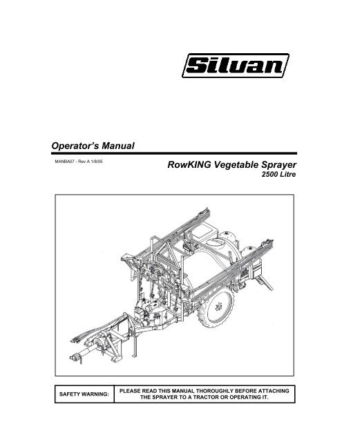
Operator’s <strong>Manual</strong><br />
MANBA07 - Rev A 1/8/05<br />
RowKING Vegetable Sprayer<br />
2500 Litre<br />
SAFETY WARNING:<br />
PLEASE READ THIS MANUAL THOROUGHLY BEFORE ATTACHING<br />
THE SPRAYER TO A TRACTOR OR OPERATING IT.
No liability can be accepted for any inaccuracies or omissions<br />
in this publication, although due care has been taken to make it<br />
as complete and accurate as possible.<br />
The information, illustrations and technical data were<br />
considered to be correct at the time of preparation.<br />
In accordance with our policy of continuous development<br />
<strong>Silvan</strong> <strong>Australia</strong> Pty. Ltd. reserves the right to make changes<br />
at any time without notice and without incurring any obligation.<br />
YOUR SPRAYER DETAILS<br />
Record the details of your RowKING sprayer here for future reference when<br />
discussing service with your <strong>Silvan</strong> dealer, ordering parts or making a warranty claim.<br />
SERIAL NUMBER<br />
MODEL<br />
DATE OF DELIVERY<br />
SELLING DEALER<br />
ADDRESS<br />
TELEPHONE NO.<br />
INSTALLED BY<br />
_____________________________<br />
________________________________________________<br />
_____________________________<br />
________________________________________________<br />
________________________________________________<br />
_____________________________<br />
_____________________________
Contents<br />
Page<br />
Introduction 2<br />
Warranty<br />
About Your Warranty 2<br />
New Product Warranty 3<br />
Safety Information 4<br />
Features and Specifications 7<br />
Description of Fluid Flow 10<br />
Installation<br />
Cabin Controls - Silvamatic and Farmscan 12<br />
Boom Cabin Controls, Adjusting Axle Track Width 13<br />
Matching Hydraulic Motor to Tractor (Hydraulic Model only) 13<br />
Connecting to the Tractor<br />
Hitching to the Tractor 15<br />
Connecting the PTO Shaft (PTO Drive Model only) 15<br />
Connecting Hydraulic Hoses and Electrical Looms 16<br />
Operation<br />
Filling the Main Tank, Bottom Filter 17<br />
Filling the Flushing Tanks 17<br />
Fresh Water Tank, Suction Filter 18<br />
Starting the Sprayer for the First Time 18<br />
Silvamatic Controls - Initial Start Up 18<br />
Setting Pressure Compensators 19<br />
Regular Operation 19<br />
Farmscan Controller - Initial Start Up 19<br />
Regular Operation 20<br />
Pump Operating Speed 20<br />
Adding Chemicals - Through Top Opening 20<br />
With Silmix and Silmix Probe 21<br />
Venturi Agitator 21<br />
Stopping the Sprayer Pump (Hydraulic Drive Model only) 22<br />
Draining the Tank, Flushing the System 22<br />
Road Travel 22<br />
Spray Boom Operation – Electric over Hydraulic Controls 23<br />
Folding and Unfolding 23<br />
Setting Boom Height 24<br />
Outer Section Break-Back 24<br />
Outer Arm Fold, Boom Tilt 24<br />
Spraybar Operation 24<br />
General Spraying Information 25<br />
Calibrating the Sprayer<br />
Nozzle Selection, Nozzle Chart 26<br />
Testing the Spray Pattern 27<br />
Verifying the Calibration, Nozzle Test and Boom Test 27<br />
Nozzle Care and Maintenance 27<br />
Optional Equipment<br />
Foam Marker, Farmscan Spray Controller 28<br />
Digital Fill Meter, Mudguards 29<br />
Boom Fence Line Kit 29<br />
Lubrication and Maintenance<br />
Start-up Inspection, Daily Maintenance 30<br />
Annual Maintenance 31<br />
1
Introduction<br />
<strong>Silvan</strong> is an <strong>Australia</strong>n owned company<br />
specialising in the supply of crop protection<br />
equipment to primary producers. A leader in the<br />
design of agricultural sprayers, the company<br />
was established in 1962 and has grown to<br />
become the largest manufacturer and supplier of<br />
crop protection equipment in <strong>Australia</strong>.<br />
Our operations are fully accredited to the<br />
international quality standard ASNZS ISO 9002-<br />
1994 and we are extremely proud of our<br />
reputation for quality products backed by quality<br />
service. Your investment in a <strong>Silvan</strong> sprayer is<br />
an investment in quality.<br />
This manual covers the 2500 litre RowKING<br />
Vegetable Sprayer with PTO or hydraulically<br />
driven pump and front or rear mounted boom.<br />
These sprayers have been designed and<br />
manufactured to provide a high standard of<br />
performance and safety and incorporate many<br />
innovative features.<br />
To ensure continued efficient performance and<br />
safe operation of your sprayer, you need to read<br />
this manual thoroughly and fully familiarise<br />
yourself with all aspects of the sprayer’s<br />
operation, maintenance and safety procedures.<br />
Now that you are a proud <strong>Silvan</strong> owner, all our<br />
services and dealer support are available to you<br />
should you need them. We assure you of our<br />
best attention at all times.<br />
Note: Because RowKING sprayers can be<br />
supplied from <strong>Silvan</strong> with a variety of spray<br />
booms, this manual only contains information<br />
relevant to the tanker unit and the general<br />
operation of the boom. For information about<br />
boom adjustment and maintenance consult the<br />
Spray Boom Operator’s <strong>Manual</strong>, which is<br />
supplied in addition to this manual.<br />
About Your Warranty<br />
<strong>Silvan</strong> <strong>Australia</strong> Pty. Ltd. welcomes any warranty<br />
repair and apologises for any inconvenience.<br />
See the previous page for the express warranty<br />
coverage offered. The following information will<br />
assist your understanding of warranty<br />
procedures.<br />
Any authorised <strong>Silvan</strong> dealer service outlet can<br />
perform warranty repairs for you, however, we<br />
recommend that such repairs be carried out by<br />
the Dealer from whom you bought the product.<br />
Most warranty repairs are handled routinely, but<br />
sometimes requests cannot be accepted under<br />
warranty. Normal wear and tear is not covered<br />
by warranty nor does warranty apply if a product<br />
failure can be attributed to abuse or neglect.<br />
Whilst <strong>Silvan</strong> will abide by its warranty policy<br />
under all genuine circumstances, we must<br />
emphasise that such can only apply when our<br />
equipment has been used in applications for<br />
which it was designed and manufactured and<br />
that a reasonable degree of care and common<br />
sense has been exercised by the operator.<br />
To avoid misunderstandings, which might occur<br />
between the customer and the service outlet,<br />
items subject to normal wear and tear such as<br />
drive belts, solenoid diaphragms, pump<br />
diaphragms, mechanical seals, spray nozzles<br />
and similar items are not covered under<br />
warranty.<br />
Warranty Repair Site<br />
The warranty provides for repairs to be carried<br />
out at the servicing dealer’s normal place of<br />
business. An owner may elect to have repairs<br />
carried out at his own residence but, whilst<br />
<strong>Silvan</strong> will accept the actual repair cost of the<br />
failed component(s), the travelling costs will not<br />
be covered under warranty - see following.<br />
Items Not Covered By Warranty<br />
The warranty does not allow for the cost of the<br />
following items. These are the responsibility of<br />
the owner.<br />
1) Labour to travel to and from a broken-down<br />
product or for any distance charges.<br />
2) Labour premiums that might apply for any<br />
repairs that are made outside the dealer’s<br />
normal business hours.<br />
3) Transportation costs of the machine to and<br />
from the service outlet.<br />
4) Freight costs to get parts to and from the<br />
service outlet.<br />
5) All communication costs made by the owner<br />
in connection with the warranty repair.<br />
2
New Product Warranty<br />
WARRANTY POLICY<br />
<strong>Silvan</strong> <strong>Australia</strong> Pty. Ltd. warrants to its authorised dealer, who in turn warrants to the<br />
original purchaser (owner) of each new <strong>Silvan</strong> product, that it will repair or replace,<br />
without charge for labour or parts, any defective or malfunctioning parts in accordance<br />
with the warranty limitations and adjustments schedule below.<br />
PRODUCT – ALL<br />
PRIVATE DOMESTIC USE – 12 MONTHS<br />
PRIVATE and COMMERCIAL AGRICULTURAL USE – 12 MONTHS<br />
AGRICULTURAL CONTRACTORS – 6 MONTHS<br />
GOVERNMENT and MUNICIPAL DEPARTMENTS – 6 MONTHS<br />
ALL OTHER NON-AGRICULTURAL APPLICATIONS – 3 MONTHS<br />
HIRE COMPANIES – 3 MONTHS<br />
The warranty period will begin on the date the product is delivered to the first retail<br />
purchaser.<br />
THIS WARRANTY COVERS:<br />
• Claims resulting from defects in workmanship or material under normal use and service.<br />
THIS WARRANTY DOES NOT COVER:<br />
• Conditions resulting from misuse, negligence, alteration, accidental damage or failure to<br />
perform normal maintenance services;<br />
• Any product which has been repaired by other than an authorised <strong>Silvan</strong> <strong>Australia</strong> Pty.<br />
Ltd. service outlet so as, in any way in the sole and absolute judgement of <strong>Silvan</strong><br />
<strong>Australia</strong> Pty. Ltd., to affect adversely its performance and reliability;<br />
• The replacement of wear and tear items such as diaphragms, V belts and ground<br />
engaging components;<br />
• Loss of time, inconvenience, loss of use of the product or any other consequential<br />
damages.<br />
The repair of defective products qualifying under this warranty will be performed by an<br />
authorised <strong>Silvan</strong> <strong>Australia</strong> Pty. Ltd. service outlet within a reasonable time following the<br />
delivery of the product, at the cost of the owner, to the service outlet’s place of business.<br />
The product will be repaired or replaced, using new parts sold by <strong>Silvan</strong> <strong>Australia</strong> Pty.<br />
Ltd.<br />
The owner is responsible for the performance of regular maintenance services as<br />
specified in the Operator’s <strong>Manual</strong> applicable to the product.<br />
• THIS WARRANTY IS THE ONLY WARRANTY APPLICABLE TO SILVAN<br />
AUSTRALIA PTY. LTD. NEW PRODUCTS AND, TO THE MAXIMUM EXTENT<br />
PERMITTED BY LAW, IS EXPRESSLY IN LIEU OF ANY OTHER WARRANTIES<br />
EXPRESSED OR IMPLIED, INCLUDING ANY IMPLIED WARRANTY OF<br />
MERCHANTABILITY OR FITNESS FOR A PARTICULAR PURPOSE.<br />
• SILVAN AUSTRALIA PTY. LTD. DOES NOT AUTHORISE ANY PERSON TO<br />
CREATE FOR IT ANY OTHER OBLIGATION OR LIABILITY IN CONNECTION WITH<br />
THESE PRODUCTS.<br />
• SUBJECT ONLY TO LEGISLATIVE OBLIGATIONS TO THE CONTRARY, SILVAN<br />
AUSTRALIA PTY. LTD. SHALL NOT BE LIABLE FOR INCIDENTAL OR<br />
CONSEQUENTIAL DAMAGES RESULTING FROM A PRODUCT PERFORMING IN<br />
BREACH OF THIS WRITTEN WARRANTY.<br />
3
Safety Information<br />
Before operating the sprayer read the following safety instructions.<br />
Failure to comply with these warnings may result in serious injury or death.<br />
Whilst your RowKING sprayer has been designed and manufactured to incorporate all<br />
necessary safety features it is essential that any person who operates or works on the machine<br />
is aware of the safety precautions that should be exercised.<br />
This sprayer is designed and manufactured<br />
solely for the purpose of applying agricultural<br />
chemicals to crops. Under no circumstances<br />
should it be used for any other purpose.<br />
Before using the sprayer carefully read and<br />
ensure you understand the contents of this<br />
manual and any other manual supplied with the<br />
sprayer.<br />
Before operating the sprayer read all the safety<br />
warnings which are carried on various parts of<br />
the machine. Refer to the next two pages for a<br />
location diagram and the wording of these<br />
warnings.<br />
Never allow an inadequately trained person to<br />
attach or operate the sprayer.<br />
Do not operate the sprayer whilst wearing loose<br />
clothing, unrestrained long hair, jewellery or<br />
anything which could become entangled in<br />
rotating components or limit your vision.<br />
Only operate the sprayer on a tractor fitted with<br />
a roll-over protective structure (ROPS), or a cab<br />
incorporating a ROPS, complying with AS1636<br />
or equivalent.<br />
Wear ear protection when operating the sprayer<br />
on a tractor that is not fitted with a sound<br />
proofed cabin.<br />
Ensure the operating capacity of the tractor<br />
matches the weight and power requirement of<br />
the sprayer. Refer to the tractor operator’s<br />
manual for safe working loads and relevant<br />
tractor safety instructions.<br />
Exercise extreme care when operating in hilly<br />
or uneven terrain to ensure proper stability.<br />
Refer also to the tractor manufacturer’s<br />
operating and safety instructions.<br />
Never allow anyone to ride on the sprayer.<br />
Do not operate the sprayer without all the<br />
tractor and sprayer safety shields in place.<br />
Apply the parking brake and switch off the<br />
tractor engine before performing any service<br />
work on the sprayer. Ensure the sprayer and<br />
boom are properly supported and restrained<br />
before performing any maintenance work.<br />
The sprayer can be supported by the folding<br />
stand if the tank is full or partly filled with liquid<br />
but take care to select a firm level surface.<br />
Do not stand under or perform maintenance<br />
work on the boom without first supporting it to<br />
ensure it cannot drop due to inadvertent<br />
operation of controls or hydraulic failure.<br />
Relieve all hydraulic pressure before<br />
disconnecting hoses. Oil escaping under<br />
pressure can penetrate the skin, causing<br />
serious injury. Seek medical advice immediately<br />
if injured by escaping oil.<br />
Before use of any chemicals refer to the<br />
chemical manufacturer’s label and safety<br />
instructions for safe handling procedures and<br />
correct method of use. Always use the<br />
recommended personal protective clothing and<br />
equipment.<br />
Ensure that all operators and associated<br />
personnel are familiar with the legal regulations<br />
and codes of practice that apply to the safe use,<br />
storage and disposal of spray chemicals.<br />
Do not enter the sprayer tank under any<br />
circumstances. If service to the tank is<br />
required contact <strong>Silvan</strong> for correct maintenance<br />
procedures.<br />
Ensure that all chemicals used in the sprayer<br />
are compatible with all components of the<br />
sprayer.<br />
4
Safety Information<br />
Locations of Safety Warnings<br />
The locations of the safety warning decals fitted to the 2500 litre RowKING sprayer are shown below. The<br />
following page shows the wording on these decals. Refer to the Spray Boom Operator’s <strong>Manual</strong> for<br />
information on safety warning decals fitted to the boom.<br />
It is important that all operators read and follow the information given on all safety decals. They should be<br />
kept clean and legible at all times. If any are missing or unreadable they should be replaced by ordering<br />
new decals from your <strong>Silvan</strong> dealer under the part numbers shown.<br />
Part No. 399 14 1000<br />
PTO Drive Model Only<br />
Part No. DEC 48<br />
Part No. DEC 52<br />
Part No. DEC 13<br />
Part No. DEC 121<br />
Both sides<br />
FILLING CONTROL PANEL<br />
Part No. DEC 52<br />
PRESSURE CONTROL PANEL<br />
Part No. DEC 10<br />
Part No. DEC 48<br />
Part No. DEC 52<br />
Part No. DEC 12<br />
Part No. DEC 119<br />
Both sides<br />
Part No. DEC 51<br />
Part No. DEC 91<br />
Spray Nozzle<br />
Selection Chart<br />
Decal positions shown for PTO model with front mounted boom.<br />
Decal positions for other models are similar.<br />
5
Safety Information<br />
Wording of Safety Warnings<br />
The wording of the safety decals shown on the previous page is given below.<br />
Before operating the sprayer read all safety warning decals.<br />
Failure to comply with these warnings could result in serious injury or death<br />
Part Number DEC 48<br />
Part Number DEC 13<br />
Part Number DEC 10<br />
Part Number DEC 12<br />
Part Number DEC 51 Part Number DEC 52<br />
Part Number DEC 121<br />
Part Number DEC 119<br />
6<br />
Part Number 399 14 1000
Features and Specifications<br />
Tank<br />
Polytuff impact resistant polyethylene.<br />
Capacity 2500 litres.<br />
455 mm screw down lid with basket strainer.<br />
Calibrated liquid level sight gauge.<br />
Dual rotating chemical rinse nozzles inside tank.<br />
50 mm bottom drain with ball valve.<br />
Bottom Fill<br />
50 mm cam-lever hose coupling.<br />
High capacity filter.<br />
Agitation<br />
Continuous agitation from by-pass flow line plus<br />
high volume venturi agitator.<br />
Pump and Drive<br />
PTO Drive Model<br />
Three cylinder, constant displacement, oil backed<br />
diaphragm pump.<br />
Direct coupled to 540 rpm shielded PTO shaft.<br />
Standard<br />
Pump Model No.<br />
BP151/20<br />
Max flow (l/min) 142<br />
Max pressure (Bar)<br />
20 (290 psi)<br />
Hydraulic Drive Model<br />
Centrifugal pump with cast iron body, glass nylon<br />
impellor, viton seals and self-priming chamber.<br />
Direct coupled to hydraulic motor suitable for<br />
closed or open centre systems.<br />
Pump Model No. Hypro 9303C-HM4C-SP<br />
Max flow (l/min) 360<br />
Max pressure (Bar) 5.5 (80 psi)<br />
Tractor hydraulic flow required 19 - 26 l/min<br />
(4.2 - 5.7 Imp GPM)<br />
Cabin Controls<br />
Standard<br />
Silvamatic Spray Controller<br />
Master On/Off switch.<br />
Boom section On/Off for up to 5 sections<br />
Spraying pressure regulating switch.<br />
Pressure gauge 0 - 20 Bar.<br />
Circuit protection fuse 10 amp.<br />
Optional<br />
Farmscan Primo 400 Spray Controller<br />
Programmable spray computer<br />
with single function digital display panel.<br />
Power switch.<br />
Boom switches - Master and 4 sections.<br />
Valve Block Assembly<br />
Flow Sensor and Flow Control valve.<br />
Electric On/Off valves for 3, 4 or 5 boom sections.<br />
Glycerine filled pressure gauge (at front of sprayer)<br />
Maximum Pressure 20 Bar<br />
Operating Voltage 12 volt DC<br />
Spray Boom – Front or Rear Mounted<br />
Front mounted <strong>Silvan</strong> RowMASTER folding boom<br />
of 12 or 15 metre width.<br />
Requires three sets of remote hydraulic outlets.<br />
Optional electric over hydraulic 3 bank controls for<br />
lift, inner fold and outer fold.<br />
Optional individual wing tilt and 5 bank controls.<br />
or<br />
Rear mounted <strong>Silvan</strong> RowMASTER folding boom<br />
of 12 or 15 metre width.<br />
Requires two sets of remote hydraulic outlets.<br />
Optional electric over hydraulic 3 bank controls for<br />
lift, inner and outer fold.<br />
Optional individual wing tilt and 5 bank controls.<br />
or<br />
Rear mounted <strong>Silvan</strong> PaddockKING folding boom<br />
of 18 or 21 metre width.<br />
See relevant boom manual for specifications.<br />
Filtration<br />
Four stage with removable elements.<br />
Standard mesh shown. Alternatives available.<br />
1) Tank lid strainer 18 mesh.<br />
Bottom fill filter 50 mesh (blue)<br />
2) Suction line filter 80 mesh (grey)<br />
3) High pressure filter 100 mesh (red)<br />
4) Nozzle strainers 50 mesh (<strong>Silvan</strong> booms)<br />
Chassis, Wheels and Suspension<br />
Heavy duty galvanised steel chassis.<br />
Three point linkage swivelling hitch.<br />
Folding support stand.<br />
Single axle with adjustable track.<br />
Track widths 1524mm min. to 1828mm max.<br />
(60 inches to 72 inches)<br />
Tyre size & pressure – 11.2 x 44 radial - 45 psi.<br />
Standard Equipment<br />
Flushing Tanks<br />
two 100 litre<br />
Fresh Water Tank<br />
14 litre<br />
Silmix - with 60 litre hopper on drop down frame<br />
for induction of powdered chemicals.<br />
Optional Equipment<br />
Foam Marker<br />
Arag digital flow meter.<br />
Boom fence line kit.<br />
100 litre<br />
Dimensions and Weights<br />
With standard equipment, single axle and 15m<br />
front boom. Mass with tanks empty. To calculate<br />
Gross Mass add 1 kg per litre of water fill.<br />
Length Width Height Mass Max.Gross Mass<br />
(dimensions in mm) (kg) (kg)<br />
5750 2550 3100 2500 5200<br />
Tractor Requirement<br />
Minimum recommended PTO power rating.<br />
75 Kw (100 HP)<br />
7
Features and Specifications<br />
Bottom Fill<br />
Filter<br />
Fill Control Panel<br />
Fill Control Panel<br />
(Not visible<br />
in this view)<br />
Two 100 litre<br />
Flushing Tanks<br />
Main Tank<br />
Top Fill Lid<br />
2500 litre<br />
Main Tank<br />
Optional<br />
Fill Meter<br />
Front Mounted<br />
Boom Lift Frame<br />
Main Tank Contents<br />
Sight Gauge<br />
Boom<br />
Transport Saddle<br />
Bottom Fill<br />
Connection<br />
Bottom Fill<br />
Valve<br />
Folding<br />
Access Steps<br />
60 litre Simix<br />
Chemical Inductor<br />
(in transport position)<br />
Silmix<br />
Controls<br />
11.2 x 44 Radial Tyres<br />
on adjustable track axle<br />
Adjustable Height<br />
Ball Hitch<br />
14 litre<br />
Fresh Water<br />
Tank<br />
Optional<br />
Foam Marker<br />
100 litre Tank<br />
and<br />
Compressor<br />
Standard Boom<br />
Lift and Fold Hydraulic Hoses<br />
(single hose<br />
electric over hydraulic<br />
system optional)<br />
Main Tank<br />
Drain Valve<br />
System Pressure<br />
Regulator<br />
and Gauge<br />
Pressure Control Panel<br />
Adjustable Length<br />
Drawbar<br />
PTO Shaft<br />
and Diaphragm Pump<br />
(replaced by<br />
hydraulic motor and centrifugal pump<br />
on hydraulic drive model)<br />
Three Point<br />
Linkage Frame<br />
Pressure Control<br />
Folding Panel<br />
Support Stand<br />
Suction<br />
Filter<br />
FEATURES OF THE RowKING 2500 LITRE VEGETABLE SPRAYER – FRONT MOUNTED BOOM MODEL<br />
PTO Drive Model shown with Boom removed<br />
Suction Valve<br />
Tank Rinse Tap<br />
Silmix Tap<br />
Agitator Tap<br />
8
Features and Specifications<br />
2500 litre<br />
Main Tank<br />
Main Tank<br />
Top Fill Lid<br />
Two 100 litre<br />
Flushing Tanks<br />
14 litre<br />
Fresh Water<br />
Tank<br />
Main Tank Contents<br />
Sight Gauge<br />
PTO Shaft and Diaphragm Pump<br />
(replaced by<br />
hydraulic motor and centrifugal pump<br />
on hydraulic drive model)<br />
Suction Valve<br />
System Pressure<br />
Regulator<br />
and Gauge<br />
Three Point<br />
Linkage Frame<br />
11.2 x 44 Radial Tyres<br />
on adjustable track axle<br />
Main Tank<br />
Drain Valve<br />
Optional<br />
Foam Marker<br />
100 litre Tank<br />
and<br />
Compressor<br />
(hidden)<br />
Standard Boom<br />
Lift and Fold Hydraulic Hoses<br />
(single hose electric over hydraulic system optional)<br />
Fill Control Panel<br />
Adjustable Length<br />
Drawbar<br />
Adjustable Height<br />
Ball Hitch<br />
Folding<br />
Support Stand<br />
Pressure<br />
Control Panel<br />
Suction Filter<br />
Pressure Control Panel<br />
Folding Access Steps<br />
(not visible in this view)<br />
Agitator Tap<br />
Tank Rinse Tap<br />
Silmix Tap<br />
Boom Transport<br />
Saddle<br />
Rear Mounted<br />
Boom Lift Frame<br />
Bottom Fill<br />
Filter Bottom Fill<br />
Connection<br />
Optional<br />
Bottom Fill<br />
Fill Meter<br />
Valve<br />
Fill Control Panel<br />
(not visible in this view)<br />
60 litre Silmix<br />
Chemical inductor<br />
(in transport position)<br />
Silmix<br />
Controls<br />
FEATURES OF THE RowKING 2500 LITRE VEGETABLE SPRAYER – REAR MOUNTED BOOM MODEL<br />
PTO Drive Model shown with Boom removed<br />
9
Description of Fluid Flow<br />
Tank Rinse<br />
Nozzle<br />
Flushing<br />
Tanks<br />
Main Tank<br />
Venturi<br />
Agitator<br />
To<br />
Silmix<br />
System<br />
Pressure<br />
Gauge<br />
Bottom Fill<br />
Connection<br />
Pressure<br />
Relief<br />
Valve<br />
Drain<br />
Valve<br />
Bottom Fill<br />
Valve<br />
Silmix<br />
Tap<br />
Tank<br />
Rinse<br />
Tap<br />
Agitator<br />
Tap<br />
High<br />
Pressure<br />
Filter<br />
Pump<br />
Pressure<br />
Regulator<br />
Flow<br />
Meter<br />
Bottom Fill<br />
Filter<br />
Suction<br />
Filter<br />
Boom Section<br />
Valves<br />
Suction<br />
Valve<br />
Four Section Spray Boom<br />
SCHEMATIC CIRCUIT DIAGRAM<br />
10
Description of Fluid Flow<br />
The schematic diagram on the previous page<br />
shows the fluid flow and filtration system of the<br />
RowKING 2500 litre sprayer. A typical four section<br />
spray boom is shown but the operating principles<br />
are the same for booms with three sections.<br />
Tanker Circuit<br />
The tanks can be filled either through the top or<br />
bottom but the usual method is through the bottom<br />
fill connection, which is more convenient and<br />
prevents chemicals from frothing.<br />
The bottom fill incorporates a cam-lever hose<br />
coupling and a high volume filter. It can be used to<br />
fill either the main tank or the two flushing tanks by<br />
turning the handle of the bottom fill valve, below<br />
the filling control panel, to the appropriate position.<br />
During filling, the suction valve must be set to<br />
‘Main Tank’ at the pressure control panel. After<br />
filling, the bottom fill valve is turned to the closed<br />
position and the suction valve is switched to either<br />
‘Main Tank’ or ‘Flush Tank’ to enable fluid to flow<br />
from the selected tank to the pump.<br />
If the top lids are used for filling, a basket strainer<br />
is provided in the fillers of the main and flushing<br />
tanks to prevent entry of foreign material.<br />
The level of liquid in the main tank is shown by a<br />
sightline at the RH front of the sprayer and for<br />
rapid emptying a large diameter outlet discharges<br />
through a manual drain valve under the LH side of<br />
the sprayer. An optional digital fill meter can be<br />
fitted to measure the amount of fluid entering both<br />
the main tank and the flushing tanks.<br />
The hand wash tank is filled by attaching a hose to<br />
its connector.<br />
The liquid to be sprayed is drawn from the<br />
underside of the tank through the suction line to<br />
the inlet side of the pump. A filter in the suction<br />
line ensures that no foreign material enters the<br />
pump. The suction valve on the control panel<br />
should be closed to allow the element to be<br />
removed for cleaning while there is liquid in the<br />
tank. Depending upon the sprayer model, the<br />
pump is directly driven either by the tractor PTO or<br />
by a hydraulic motor connected to the tractor<br />
hydraulics.<br />
Fluid is discharged from the pump to a pressure<br />
relief valve mounted on the pressure control panel.<br />
This valve is manually operated to set the<br />
maximum pressure within the system. The required<br />
spraying pressure can then be regulated from the<br />
control unit in the tractor cab, up to the maximum<br />
set at the manual valve. The gauge on the<br />
pressure control panel shows the system<br />
maximum pressure.<br />
From the relief valve, fluid is directed to the spray<br />
boom at system pressure through a high pressure<br />
filter under the control panel. This filter can be<br />
purged by means of a knob at the filter that opens<br />
a valve connected to a return line to the tank.<br />
Surplus capacity from the pump is by-passed at<br />
the main relief valve. If the boom valves are<br />
closed, or if the pump is producing more volume<br />
than required at the boom, the outlet pressure will<br />
rise until the relief valve opens and the excess is<br />
by-passed to the bottom of the tank, thus keeping<br />
the contents well mixed.<br />
Selecting the agitator valve on the pressure control<br />
panel opens the agitator valve and provides<br />
additional mixing of the main tank contents by<br />
directing pressurised fluid to the venturi jet in the<br />
rear of the tank.<br />
To flush the system with clean water from the<br />
flushing tank, the suction valve on the pressure<br />
control panel is switched to ‘Flush Tank’. To wash<br />
the interior of the main tank the ‘Tank Rinse’ valve<br />
can be opened on the pressure control panel. This<br />
pumps pressurised water to the rotating rinse jet in<br />
the top of the tank and also rinses the main tank<br />
sightline.<br />
Spraying Controls<br />
Fluid from the high pressure filter is directed to the<br />
boom sections via electrically operated on/off<br />
valves in the valve block mounted at the rear of the<br />
sprayer. The valves are operated from the cabin<br />
using the control unit and can be opened or closed<br />
independently by selecting the required section<br />
switches or, once a pattern is selected, as a group<br />
by operating the Master switch that controls the<br />
main on/off valve.<br />
If a spray computer is fitted, the valve block<br />
incorporates a flow meter that is electrically<br />
connected to the spray computer. Once the<br />
spraying pressure and application rate are set they<br />
are monitored by the flow meter and maintained by<br />
the by-pass or throttling action of the pressure<br />
regulator in the valve block.<br />
All <strong>Silvan</strong> booms are fitted with interchangeable fan<br />
jet nozzles at 50 cm intervals in non-drip bayonet<br />
holders that incorporate a strainer for final filtration.<br />
11
Installation<br />
Before attaching the sprayer to the tractor, install<br />
the cabin control units supplied with the sprayer.<br />
On the hydraulic drive model it may also be<br />
necessary to adjust the sprayer hydraulic motor to<br />
match the tractor hydraulic system, refer page 14.<br />
Silvamatic Spray Controller<br />
Install the control box in the tractor cabin using the<br />
hardware provided. Ensure it is clearly visible and<br />
within easy reach of the driver. The master switch<br />
should be in the “Off” position whilst installing.<br />
Plug the short electrical loom into the rear of the<br />
control box and connect the free end directly to the<br />
battery. The connections are:<br />
Positive = Brown Negative = Blue<br />
If the cable needs extending it is important to use<br />
wire of the same diameter (no less than 0.75mm 2 ).<br />
Plug the terminal block of the front section of the<br />
main loom into the rear of the control box and run<br />
the quick coupling end of the loom through a<br />
convenient opening in the tractor cabin. If it is<br />
necessary to drill a hole for the loom install a<br />
rubber grommet so that the cable is not chaffed.<br />
Remove the protective cap from the threaded<br />
connection of the pressure gauge on the rear of<br />
the cabin control and screw on the reduction fitting,<br />
then screw the 1/8in threaded hose connector to<br />
the reduction fitting. Use a small amount of sealant<br />
on the threads but take care to avoid clogging the<br />
gauge inlet.<br />
Insert the pressure hose into the connector on the<br />
pressure gauge and securely tighten the coupling.<br />
Run the hose back to the sprayer along the same<br />
route as the wiring loom and strap or tape it to the<br />
loom at convenient locations. Cut the hose to the<br />
appropriate length near the wiring quick connector<br />
and fit the quick release hydraulic coupling.<br />
Boom Section<br />
On/Off Switches<br />
Mounting Bracket<br />
Pressure<br />
Toggle Switch<br />
SILVAMATIC CABIN CONTROL BOX<br />
Master<br />
On/Off Switch<br />
Boom<br />
Section<br />
Switches<br />
Boom Master<br />
Switch<br />
Digital Display<br />
Computer<br />
Power Switch<br />
FARMSCAN PRIMO 400 SPRAY CONTROLLER<br />
Farmscan Primo 400 Spray Controller<br />
(Optional Equipment)<br />
Using the bracket, securing knobs and hardware<br />
provided, install the monitor in a suitably protected<br />
position within the cabin where it will be easily<br />
seen and within convenient reach. Refer to the<br />
Farmscan manual for information on important<br />
points to note when selecting the position<br />
Ensure that the power switch of the controller is off<br />
whilst making these connections. Connect the<br />
electrical power supply cables of the loom directly<br />
to the 12 volt tractor battery. The connection<br />
method and the positive and negative cable<br />
colours are shown in the Farmscan manual.<br />
Plug the rectangular end of the loom into the<br />
socket on the rear of the controller and tighten the<br />
securing screws.<br />
Run the quick coupling end of the loom through a<br />
convenient opening in the tractor cabin, taking note<br />
of the points given in the Farmscan manual.<br />
Use the cable ties provided to secure the loom. If it<br />
is necessary to drill a hole for the loom, install a<br />
rubber grommet so the cable is not chaffed.<br />
Do not switch the power on to the controller until<br />
the content of the Farmscan manual has been<br />
read and is understood.<br />
Electric Over Hydraulic Boom Controls<br />
(Optional Equipment for some models)<br />
Mount the control box in a convenient location that<br />
is clearly visible to the driver using the bracket<br />
provided.<br />
Connect the electrical cable provided directly to the<br />
battery. The connections are:<br />
Positive = Red Negative = Red/Black<br />
12
Installation<br />
Left Tilt<br />
Main Fold<br />
Right Tilt<br />
Outer Fold<br />
Lift Switch<br />
Spare<br />
Switches<br />
Foam<br />
Marker<br />
Switch<br />
Master<br />
On/Off<br />
Switch<br />
ELECTRIC OVER HYDRAULIC BOOM CONTROL BOX<br />
Run the control loom back to the sprayer through a<br />
convenient outlet in the tractor cabin ensuring that<br />
it does not rub on any sharp edges. If it is<br />
necessary to drill a hole in the cabin, fit a rubber<br />
grommet. The loom is fitted with a 4 pin quick<br />
release coupling for connecting to the sprayer.<br />
If an optional foam marker is fitted at the factory,<br />
the wiring for the marker will be incorporated in the<br />
loom and the Foam Marker switch on the control<br />
box can be used to operate the marker.<br />
Adjusting the Axle Track Width<br />
The track width between the wheels can be<br />
adjusted to suit the row spacing of the crops being<br />
sprayed. It can be set between a minimum of<br />
1524mm (60 inches) and a maximum of 1828mm<br />
(72 inches) measured between the centrelines of<br />
the tyre treads. As delivered from the factory the<br />
track is set to the minimum width.<br />
Caution: As it is necessary to get under the<br />
sprayer to adjust the track, follow the safety<br />
precautions stated below.<br />
Before adjusting the track, empty the tanks and<br />
place the sprayer on a flat hard surface. Do not lift<br />
the sprayer with fluid in the tanks.<br />
Loosen the nuts on the U-bolts at each side of the<br />
axle just sufficiently for the axle halves to be<br />
moved in or out by the turnbuckles, which are<br />
positioned on the front face of each axle half.<br />
Loosen the locknut on each turnbuckle and<br />
lengthen or shorten it, using a bar in the holes, to<br />
move the axle halves in or out until the desired<br />
track width is achieved. Adjust the turnbuckles by<br />
an equal number of turns. Measure the track width<br />
between the centres of the tyre treads.<br />
Check whether the axle is central by measuring<br />
the distance between the sprayer frame and the<br />
inner face of each tyre. This should be equal on<br />
each side. If necessary adjust the turnbuckles to<br />
centralise the axle.<br />
Position the centre bar connecting the two axle<br />
halves so the lug marking its centre is midway<br />
between the inner ends of the axle halves. This will<br />
ensure the bar is inserted equally into each axle.<br />
When the required track width has been set and<br />
the axle is centralised, tighten the locknut on each<br />
turnbuckle. Tighten the nuts on the U-bolts then<br />
tighten the 16 lock-bolts securing the axle halves<br />
to the centre bar. Recheck to ensure that all<br />
hardware is securely tightened.<br />
Raise each side of the sprayer in turn with the jack,<br />
remove the support stand and lower the sprayer.<br />
Note: U bolts are shown fully unscrewed and<br />
axle lowered for clarity of the illustration only.<br />
U bolts should only be loosened to adjust axle.<br />
Sprayer Frame<br />
Disconnect the sprayer from the tractor and<br />
support it at the front on the folding support stand.<br />
Lift each side of the sprayer in turn with an<br />
hydraulic jack and lower it onto a steel support<br />
stand placed under the main frame so that the tyre<br />
on each side is just clear of the surface.<br />
Ensure the support stands are of the same height<br />
and capable of safely supporting the weight of the<br />
sprayer (see Specifications page). Do not work on<br />
the sprayer whilst only supported by the jack.<br />
Loosen the 16 square headed lock-screws that<br />
clamp the right and left axle halves to the centre<br />
bar. On each axle half, there are four screws on<br />
the underside and four on the rear face.<br />
Turnbuckle<br />
Lock Nut<br />
Axle Half<br />
Centre Bar<br />
Square Headed<br />
Lock-screws<br />
ADJUSTING THE AXLE TRACK WIDTH<br />
U bolts<br />
13
Installation<br />
Matching the Hydraulic Motor to the Tractor<br />
Hydraulic Drive Model Only<br />
The sprayer pump motor is suitable for either an<br />
open centre or closed centre hydraulic system.<br />
Before operating the sprayer consult the tractor<br />
Operator’s <strong>Manual</strong> to determine the type of<br />
hydraulic system and its flow rate.<br />
Depending upon the type of tractor system it may<br />
be necessary to regulate the hydraulic oil flow to<br />
the sprayer motor by installing a metering orifice in<br />
the pressure port or by opening the by-pass screw.<br />
If the motor requires either of these changes it will<br />
be necessary to check the performance by test<br />
running the sprayer with water. Refer to the<br />
Operation section for information on filling the tank<br />
and running the sprayer.<br />
Motor Flow Metering Orifice<br />
No orifice is fitted to the motor as shipped from the<br />
factory. Three sizes of orifice are supplied loose<br />
with the sprayer. To install or remove an orifice:<br />
1. Disconnect the hose at the pressure port.<br />
2. Remove the port adaptor using a 1 1 / 16 ” wrench.<br />
3. To remove an orifice - tap out from the small<br />
end of the adaptor.<br />
4. To install an orifice - tap in from the large end of<br />
the adaptor. Ensure the O-ring is fitted. A snap<br />
is heard when the orifice is seated.<br />
Load Sensing Closed Center Systems<br />
Flow and pressure compensated or load sensing<br />
closed centre systems are fitted to many current<br />
tractors. Flow is adjustable by means of a control<br />
valve on the tractor. Once set the tractor maintains<br />
a constant flow of oil for a given pressure drop.<br />
Any variation in demand at the motor will cause a<br />
change in flow. Hence there is no need to restrict<br />
the flow or by-pass oil within the motor.<br />
For tractors with these systems no orifice is<br />
required in the pressure port adaptor (motor as<br />
delivered) but the by-pass screw should be fully<br />
closed and locked.<br />
Pressure Compensated Closed Centre Systems<br />
Pressure compensated closed centre systems use<br />
a variable displacement pump to deliver oil at a<br />
rate necessary to maintain the required pressure.<br />
The sprayer may be used without an orifice in the<br />
motor (as delivered) providing the pressure drop<br />
across the motor does not exceed 145 Bar (1800<br />
psi), measured with oil at operating temperature.<br />
If necessary the flow rate can be reduced by fitting<br />
a metering orifice in the motor. To determine the<br />
size required test run the system. Start with the<br />
smallest orifice. Raise the oil to operating<br />
temperature by running the motor with the by-pass<br />
screw open 3 turns for about 10 to 15 minutes.<br />
Centrifugal Pump<br />
Hydraulic<br />
Motor<br />
Pressure Port<br />
Adaptor<br />
Pump<br />
Priming Plug<br />
By-pass Screw<br />
HYDRAULIC MOTOR FLOW ADJUSTMENTS<br />
With the screw open the sprayer will not operate.<br />
When the oil has reached operating temperature<br />
fully close and lock the screw.<br />
With the boom switches “Off” set the sprayer<br />
pressure to 5.5 bar (80 psi) at the pressure relief<br />
valve. Open all boom valves with the cabin control<br />
and set the spraying pressure to 5.5 bar.<br />
If the required pressure cannot be maintained<br />
install a larger orifice or remove it altogether, until<br />
the sprayer can maintain the required pressure.<br />
Open Centre Systems<br />
In an open centre system the tractor delivers a<br />
constant oil flow at any given engine speed. If the<br />
pump delivers more oil than the sprayer motor can<br />
use a portion of the oil must be by-passed within<br />
the motor. The by-pass volume should be kept to a<br />
minimum to avoid unnecessary heat build up.<br />
If the flow rate is up to 38 l/min (8.3 Imperial GPM)<br />
no orifice is required in the pressure port (motor as<br />
delivered). Systems with a higher flow rate should<br />
be run at reduced engine speed to limit the flow or<br />
alternatively they may need an orifice installed.<br />
To adjust the by-pass flow, open the screw 2 1 / 2<br />
turns and tighten the lock nut. Run the tractor with<br />
hydraulic control in neutral for 10 to 15 minutes<br />
until the oil reaches operating temperature then<br />
engage the hydraulic control to start the sprayer.<br />
The cabin control boom switches should be “Off”.<br />
Set the system pressure to 5.5 bar (80 psi) using<br />
the pressure relief valve. Open all boom valves at<br />
cabin control and set spraying pressure to 5.5 bar.<br />
If the sprayer achieves 5.5 bar the motor by-pass<br />
setting is satisfactory.<br />
If the sprayer cannot achieve 5.5 bar close the bypass<br />
screw until this pressure is achieved. This<br />
reduces the volume of oil being by-passed and<br />
directs more to the motor drive.<br />
14
Connecting to the Tractor<br />
Adjustable Length<br />
Drawbar<br />
Tension Spring<br />
and Chain<br />
Hitch Height<br />
Adjustment Holes<br />
and<br />
Attaching Bolts<br />
When the hitching set-up is correct, raise the<br />
sprayer with the tractor linkage, remove the locking<br />
pin from the folding support stand and swing the<br />
stand up to the transport position. Reinstall the pin<br />
in the upper hole and secure it with the ‘R’ clip.<br />
PTO Shaft<br />
Support Hook<br />
Sprayer<br />
TPL Frame<br />
Reversible<br />
Swivel Hitch<br />
SPRAYER HITCH AND SUPPORT STAND<br />
Locking Pin<br />
and<br />
‘R’ Clip<br />
Folding<br />
Support Stand<br />
Hitching to the Tractor<br />
The sprayer TPL (three point linkage) frame should<br />
be level when the sprayer main frame is horizontal<br />
and the tractor three point linkage is at a suitable<br />
operating height. The sprayer main frame is<br />
horizontal when supported by the folding leg on<br />
level ground.<br />
Connect the sprayer TPL frame to the tractor<br />
linkage using the linkage pins supplied with the<br />
sprayer. Set the tractor linkage to the required<br />
operating height. Adjust the height of the swivel<br />
hitch at the front of the sprayer so that the TPL<br />
frame is approximately level.<br />
The height of the sprayer hitch can be adjusted by<br />
removing the four attaching bolts and installing it in<br />
the high, mid or low position. The range of<br />
adjustment can be further extended by rotating the<br />
hitch whilst unbolted so that the tongue is either to<br />
the top or the bottom. Ensure that the attaching<br />
bolts are securely tightened.<br />
The length of the drawbar on the TPL frame should<br />
be adjusted so that the swivel hitch is<br />
approximately mid-way between the tractor rear<br />
axle and the sprayer axle to provide the best<br />
turning geometry. To adjust the length of the<br />
drawbar remove the two horizontal bolts and slide<br />
it to align with one of the three bolt positions. After<br />
adjusting re-install the bolts and securely tighten.<br />
The tension spring supports the TPL frame when it<br />
is disconnected from the tractor to facilitate<br />
hitching. The length of the chain should be set so<br />
that the TPL frame is approximately level when<br />
disconnected from the tractor.<br />
Connecting the PTO Shaft (PTO Model Only)<br />
The sprayer TPL frame should be set so the PTO<br />
shaft is approximately horizontal when attached to<br />
the tractor to minimise the joint angles.<br />
Clean and grease the splines on the tractor and<br />
sprayer PTO stub shafts and install the PTO shaft<br />
making sure that the spring loaded locking pins<br />
engage in the grooves of both stub shafts.<br />
Ensure that the tractor’s PTO shaft guard is<br />
attached to the tractor.<br />
The ‘U’ shaped hook on the sprayer TPL frame is<br />
used to support the PTO shaft when it is<br />
disconnected from the tractor.<br />
Note: Upon delivery of a new sprayer it is the<br />
selling dealer’s responsibility to install and set the<br />
PTO shaft to the correct length. The following<br />
information is provided for reference.<br />
The telescoping tubes must overlap by at least 1/3<br />
their length, but not less than 150mm, in all<br />
possible operating positions and there must be at<br />
least 25mm telescopic movement remaining at the<br />
minimum operating length, refer diagram below.<br />
If the PTO shaft has to be shortened cut equal<br />
amounts from both male and female shafts and<br />
safety covers. Carefully remove all burrs then<br />
clean and relubricate before reassembling.<br />
PTO SHAFT LENGTH<br />
15
Connecting to the Tractor<br />
Connecting Hydraulic Hoses<br />
Relieve all hydraulic pressure<br />
before connecting or disconnecting<br />
hoses. Oil escaping under pressure<br />
can penetrate skin, causing serious<br />
injury. Seek immediate medical<br />
treatment if injured by escaping oil.<br />
When attaching or removing hydraulic hoses<br />
ensure that the quick release connections are<br />
clean to avoid contaminating the system.<br />
Ensure that the hoses are well supported and clear<br />
of the tractor wheels.<br />
Hydraulic Drive Model<br />
A pair of 1/2’’ diameter hoses are used to drive the<br />
spray pump motor. The pressure hose is identified<br />
with a red tag. Plug the hoses into the tractor<br />
remote outlets with the pressure and return hoses<br />
in the corresponding tractor sockets.<br />
The tank (out) adaptor of the hydraulic motor<br />
incorporates a check valve which guards against<br />
reverse operation if the hoses are inadvertently<br />
connected in the opposite manner. It also allows<br />
the flow from the tractor to be reversed (if<br />
necessary to operate other equipment, which may<br />
be attached) without the risk of damaging the<br />
sprayer. This adaptor must not be removed.<br />
Spray Boom Hoses<br />
Pressure hoses should be identified with a red tag<br />
or some similar method so they can be connected<br />
to a pressure outlet of the tractor. If the boom<br />
hoses are connected in the opposite manner no<br />
damage will be done to the boom or hydraulic<br />
components but the tractor control will work in the<br />
reverse direction. For safety reasons it is therefore<br />
important to always connect the boom hoses to the<br />
correct sockets.<br />
Booms supplied by <strong>Silvan</strong> can be fitted with an<br />
optional electric over hydraulic control unit which<br />
enables the lift and fold functions (and tilt if<br />
applicable) to be operated by a single pair of<br />
hydraulic hoses.<br />
If an electric over hydraulic control is not fitted a<br />
pair of remote outlets is required for each boom<br />
function. A tap is located on the end of the lift<br />
pressure hose to facilitate connection and<br />
disconnection. It should be turned off before<br />
removing the hose. Failure to do this will result in<br />
excessive pressure build up in the hose making it<br />
difficult to reconnect the hose. Ensure the tap is<br />
open before operating the boom.<br />
Connecting Electrical Looms<br />
Connect the electrical looms for the cabin controls.<br />
A different type of coupling is used for each system<br />
to avoid confusion.<br />
Ensure that the looms are well supported to avoid<br />
chafing and that they are clear of the tractor<br />
wheels when turning.<br />
Silvamatic Spray Controller Plug the quick<br />
release coupling on the tractor electrical loom into<br />
the socket of the sprayer loom.<br />
Connect the threaded couplings on the ends of the<br />
tractor and sprayer pressure hoses and tighten<br />
securely.<br />
Farmscan Spray Controller Remove the threaded<br />
end caps from each section of the loom and plug<br />
the two ends together, noting the position of the<br />
indexing lug, then tighten the screw coupling.<br />
When disconnecting ensure that the screw caps<br />
are refitted to each section of the loom to avoid<br />
damage or contamination of the connecting pins.<br />
Electric Over Hydraulic Boom Controls Plug the<br />
multi-pin quick release coupling on the tractor<br />
electrical loom into the socket of the sprayer loom.<br />
16
Operation<br />
Bottom Fill<br />
Filter<br />
Optional<br />
Fill Meter<br />
Bottom Fill<br />
Valve<br />
FILLING CONTROL PANEL<br />
Bottom Fill<br />
Connection<br />
Filling the Main Tank using Bottom Connection<br />
The main tank can be filled through either the top<br />
or bottom but the recommended method is through<br />
the bottom fill connection, which is more convenient<br />
and prevents chemicals frothing.<br />
Before filling, first check that the red handle of the<br />
tank drain valve is turned to the “Pump” position.<br />
The drain valve is located under the LH rear of the<br />
sprayer if a front mounted boom is fitted and the<br />
RH front of the sprayer if a rear boom is fitted.<br />
Open the bottom fill valve underneath the filling<br />
control panel by moving the red handle to “Main<br />
Tank Fill “. The fill panel is at the RH rear of front<br />
boom sprayers and LH front of rear boom models.<br />
Remove the dust cap and connect the filling hose<br />
to the bottom fill connection on the filling control<br />
panel. Then turn on the water supply.<br />
When filling is complete, shut off the supply and<br />
close the bottom fill valve by moving it to “Off”.<br />
Disconnect the hose and replace the dust cap.<br />
The red ball in the sight gauge indicates the level<br />
of liquid in the tank. The volume can be read from<br />
the litre scale. The gauge is visible from the tractor<br />
so the content can be observed whilst spraying.<br />
If an optional digital fill meter is fitted it will indicate<br />
the volume added to the tank through the bottom<br />
fill connection, refer Optional Equipment section.<br />
Using the Main Tank Top Filler<br />
If filling the tank through the top use the folding<br />
steps to gain access to the sprayer platform. The<br />
steps are secured in the transport position by a<br />
safety latch.<br />
Fill the tank through the inner screw cap. The outer<br />
cap is for access to the basket strainer or for<br />
inspection purposes (but under no circumstances<br />
enter the tank).<br />
After filling the tank fold the steps up to the<br />
transport position and secure with the safety latch<br />
before moving the sprayer.<br />
Bottom Fill Filter<br />
The high volume bottom fill filter is capable of<br />
handling a flow of 180 litres per minute. It should<br />
be checked regularly and cleaned if necessary.<br />
The standard element is 50 mesh but elements of<br />
32 and 80 mesh are also available.<br />
The filter is located on the filling control panel and<br />
can be removed by unscrewing the black plastic<br />
ring and removing the cover. Ensure the bottom fill<br />
valve is in the “Off’ position before removing the<br />
filter.<br />
Filling the Flushing Tanks<br />
The flushing tanks provide a convenient water<br />
supply for flushing the pump, valves, spray lines<br />
and nozzles with water whilst still in the paddock.<br />
This should be done whenever spraying is stopped<br />
for any length of time to avoid chemical sediment<br />
blocking the nozzles or accumulating in the lines or<br />
working parts.<br />
The flushing tanks should be filled with water at the<br />
same time as the main tank. The most convenient<br />
method is through the bottom fill system, which<br />
also utilises the high volume filter and the optional<br />
digital fill meter, if fitted.<br />
The procedure for filling the flushing tanks is the<br />
same as for the main tank except the bottom fill<br />
valve is positioned to “Flush Tank Fill”.<br />
The flushing tanks can also be filled through the<br />
top using the screw lids. The folding steps provide<br />
safe access for top filling. After filling ensure that<br />
the steps are folded up to the transport position<br />
and the latch secured before moving the sprayer.<br />
Fresh Water Tank<br />
The 14 litre fresh water tank is located at the LH<br />
front of the sprayer above the pressure control<br />
panel. The discharge tap is located at the front of<br />
the tank.<br />
The tank can be filled through the discharge outlet,<br />
which is fitted with a ½” hose snap coupling and a<br />
protective cover. The tap must be opened when<br />
filling through the discharge outlet.<br />
This tank is intended to provide water for personal<br />
washing purposes only.<br />
Under no circumstances should water in the fresh<br />
water tank ever be used for drinking.<br />
17
Operation<br />
System<br />
Pressure<br />
Regulator<br />
Suction<br />
Filter<br />
System<br />
Pressure<br />
Gauge<br />
Silmix<br />
Valve<br />
Tank<br />
Rinse<br />
Valve<br />
PRESSURE CONTROL PANEL<br />
Agitator<br />
Valve<br />
Suction<br />
Valve<br />
Suction Filter<br />
The suction filter should be cleaned after each tank<br />
of chemical mixture is emptied. This routine<br />
ensures it is ready for the next filling.<br />
The filter is located on the pressure control panel<br />
at the LH front of the sprayer. It can be removed by<br />
unscrewing the black plastic ring and removing the<br />
cover. Before removing the filter, turn the suction<br />
valve to “Off”. This prevents liquid draining from<br />
the tank when the element is removed. After<br />
reinstalling the element turn the suction valve to<br />
“Main Tank”. Refer to the Maintenance section for<br />
filter cleaning information.<br />
Starting the Sprayer for the First Time<br />
When starting the sprayer for the first time conduct<br />
a trial run using water only (no chemicals) to<br />
familiarise with the operation of the controls and to<br />
check that all systems are functioning correctly<br />
without any leakage. Fill the tank through the<br />
bottom fill for the start up run.<br />
To allow liquid to flow from the tank, switch the<br />
suction valve to “Main Tank” at the pressure<br />
control panel.<br />
On the hydraulic drive model also open the agitator<br />
and tank rinse valves on the pressure control panel<br />
to assist the initial priming of the pump by purging<br />
air from the system.<br />
The sprayer should be started in by-pass mode<br />
with the cabin controls set so that the boom will not<br />
operate. The starting procedure differs depending<br />
upon the type of controls fitted.<br />
Silvamatic Controls<br />
1. Initial Start-up<br />
At the cabin control, refer diagram on page 12, turn<br />
the master switch “Off” and close all boom<br />
switches. Hold the pressure toggle switch down for<br />
a few seconds to fully open the pressure regulating<br />
valve The electric motor will wind the valve open<br />
until stopped by the limit switch. No damage will<br />
occur if the switch is held on.<br />
At the sprayer pressure control panel, fully open<br />
the system pressure regulator by screwing it anticlockwise<br />
to the end of its travel.<br />
Start the tractor, run the engine slowly and engage<br />
the PTO, or on the Hydraulic Drive Model open the<br />
remote hydraulic flow from the tractor. Once the<br />
pump is primed, gradually increase engine speed<br />
to 540 PTO rpm.<br />
At the cabin control, set the master switch “On”<br />
then progressively increase pressure with the<br />
pressure toggle switch whilst observing the gauge.<br />
Raising the switch increases pressure and<br />
lowering it decreases pressure. For the initial trial<br />
set the pressure to the upper end of the range to<br />
be used for spraying.<br />
Move all boom section switches to “On” and check<br />
that all sections are spraying.<br />
At the sprayer pressure control panel, set the<br />
maximum system pressure by screwing the knob<br />
of pressure regulator and observing the pressure<br />
gauge on the panel. Turning the knob clockwise<br />
increases pressure and turning it anti-clockwise<br />
decreases pressure. Set the system pressure<br />
higher than that which will be used for spraying but<br />
below the maximum allowable safe working<br />
pressure of 20 Bar.<br />
Spraying is normally carried out in the range of 2 to<br />
4 Bar but the maximum system pressure should be<br />
set at least 50% higher so the proportional<br />
pressure regulator can maintain a constant<br />
application rate if travel speed changes whilst<br />
spraying. The system maintains a uniform<br />
application rate for speed changes of plus or minus<br />
15%, providing the tractor remains in the same<br />
drive gear.<br />
With the switch on the cabin control, adjust the<br />
pressure to that which is required for spraying.<br />
Refer to the section on Calibrating the Sprayer for<br />
information on spraying rates and pressures.<br />
The pressure compensators on the boom section<br />
valves can now be adjusted.<br />
18
Operation<br />
To increase pressure turn<br />
knob clockwise.<br />
To decrease pressure turn<br />
anti-clockwise.<br />
ADJUSTING PRESSURE COMPENSATORS<br />
Silvamatic Controls<br />
2. Setting the Pressure Compensators<br />
The pressure compensators ensure that spraying<br />
pressure remains constant when one or more<br />
boom section is closed or opened during spraying<br />
operations.<br />
At the cabin control, close No.1 section valve with<br />
its switch and observe the pressure gauge. At the<br />
valve block, at the centre of the front crossmember<br />
of the sprayer frame, adjust the red knob<br />
on the side of No.1 valve until the pressure is<br />
restored to the original setting. Screwing the knob<br />
clockwise raises the pressure and screwing it anticlockwise<br />
lowers pressure.<br />
Open and close the section valve several times<br />
whilst observing whether the pressure remains<br />
constant and adjust the compensator if necessary.<br />
Repeat with each section valve in turn and when<br />
all compensators have been adjusted make a final<br />
check by opening and closing each valve in turn<br />
and observing whether the pressure remains<br />
constant. Re-adjust the compensators if necessary<br />
until each valve can be opened or closed without<br />
any change in system pressure.<br />
Once correctly set the compensators will not<br />
require adjustment if the spraying pressure is<br />
changed.<br />
With the sprayer running at operating pressure and<br />
with all boom sections open, check for any leaks<br />
and tighten hoses as required.<br />
Chemicals can now be added to the system.<br />
3. Regular Operation<br />
After the initial trials the following procedure can be<br />
used for regular operation of the Silvamatic<br />
controls.<br />
1. Set the suction valve to “Main Tank”. The rinse<br />
and agitator valves should be closed. Set the<br />
master switch of the cabin control to “Off” and<br />
close all boom switches.<br />
2. Start the sprayer and set the manual pressure<br />
regulator to the required maximum system<br />
pressure.<br />
3. Turn the master switch “On” and set the<br />
required spraying pressure with the pressure<br />
switch.<br />
4. Open and close each boom section switch and<br />
check that pressure remains constant. If<br />
necessary adjust the pressure compensators as<br />
previously described.<br />
5. To commence spraying open the required<br />
boom sections with their control switches.<br />
Spraying may then be stopped and started using<br />
the master switch, so as to maintain the required<br />
boom configuration.<br />
Farmscan Primo 400 Controller – Optional<br />
1. Initial Start-up<br />
On the cabin spray controller, turn the “Master”<br />
switch off and set all boom switches to the closed<br />
position, refer drawing on page 12.<br />
The sprayer should be initially started without<br />
pressure in the system. Switch on the computer<br />
section of the controller, set the unit to manual<br />
control and set the spraying pressure to zero.<br />
Depress the down button for a few seconds to<br />
ensure the electric pressure regulating valve is<br />
fully opened. The motor will wind the valve open<br />
until stopped by its limit switch. Refer to the<br />
Farmscan Operator’s <strong>Manual</strong> for information on<br />
regulating the pressure.<br />
At the sprayer pressure control panel, open the<br />
manual pressure regulator fully by screwing the<br />
knob anti-clockwise to the end of its travel.<br />
Engage the PTO, or on the Hydraulic Drive Model<br />
open the remote hydraulic flow from the tractor,<br />
and allow the sprayer to run in by-pass mode for a<br />
few minutes. Once it is running satisfactorily the<br />
operating speed can be increased.<br />
Set the controller display to “Pressure” and<br />
progressively increase pressure. For the initial trial<br />
set the pressure to the upper end of the range to<br />
be used for spraying.<br />
Switch all boom sections on and check that all are<br />
spraying.<br />
19
Operation<br />
At the sprayer pressure control panel, set the<br />
maximum system pressure with the regulator while<br />
observing the pressure gauge. Turning clockwise<br />
increases pressure and turning anti-clockwise<br />
decreases pressure. Set the system pressure<br />
higher than that to be used for spraying but below<br />
the maximum safe working pressure of 20 Bar.<br />
Spraying is normally carried out in the range of 2 to<br />
4 Bar but the maximum system pressure should be<br />
set at least 50% higher so that the pressure<br />
regulator can function correctly.<br />
With the cabin spray controller, adjust the<br />
application rate to that required for spraying. Refer<br />
to the Calibrating the Sprayer section for<br />
information on spraying rates and pressures.<br />
2. Starting Procedure for Regular Operation<br />
After the initial trials the following starting<br />
procedure can be used for regular spraying using<br />
the Farmscan controller.<br />
1. Set the suction valve to “Main Tank”. The rinse<br />
and agitator valves should be closed.<br />
2. Set the cabin spray controller power switch to<br />
‘on’ and the master switch to ‘off’ and close all<br />
boom switches.<br />
3. Start the sprayer.<br />
4. Set the manual pressure regulator to the<br />
required maximum system pressure.<br />
5. Set the required application rate with the cabin<br />
spray controller.<br />
6. Set the cabin spray controller master switch on<br />
and open and close each boom section to<br />
check that it is functioning.<br />
7. To commence spraying open the required<br />
boom sections with their control switches.<br />
8. Spraying may then be stopped and started<br />
using the master switch on the cabin spray<br />
controller, so as to maintain the required boom<br />
configuration.<br />
Pump Operating Speed<br />
Under most spraying conditions the sprayer can be<br />
operated at less than the maximum pump speed of<br />
540 rpm.<br />
The tractor engine speed can be reduced under<br />
most conditions to save fuel and unnecessary<br />
wear. The speed chosen should ensure that the<br />
pressure set at the relief valve can be maintained<br />
when all boom sections are operating, so that fluid<br />
is by-passed to the tank to maintain agitation.<br />
The hydraulic flow available from most tractors at<br />
rated engine speed exceeds the requirements of<br />
the hydraulic drive model. If the tractor is fitted with<br />
a load sensing hydraulic system with a variable<br />
flow control this can be used to reduce the rate.<br />
Adding Chemicals<br />
Before adding chemicals read and<br />
follow the chemical manufacturer's<br />
instructions and wear the<br />
recommended protective clothing.<br />
Chemicals can be added to the tank through the<br />
top opening or more safely and conveniently<br />
through the Silmix inductor.<br />
The Silmix is ideal for adding and thoroughly<br />
mixing powdered or granulated chemicals and is<br />
fitted with a probe for inducting liquid chemicals.<br />
Before adding any chemicals fill the tank with<br />
approximately 600 litres of water.<br />
Switch the suction valve to “Main Tank” and run<br />
the sprayer to circulate the mixture whilst<br />
chemicals are being added. Ensure the boom<br />
sections are switched off so that the pump output<br />
will be by-passed at the relief valve and returned to<br />
the tank to mix the solution. The venturi agitator<br />
can also be switched on to improve the mixing of<br />
the solution.<br />
When all chemical has been added, continue filling<br />
the main tank with water and keep the sprayer<br />
running to thoroughly mix the solution.<br />
Take care to avoid the spillage of chemicals or<br />
mixed solution. Wear gloves, eye protection and<br />
the recommended protective clothing whilst filling<br />
with chemicals. Wash your hands after filling if they<br />
have come into contact with concentrate or mixed<br />
solution.<br />
Store unused chemicals and dispose of empty<br />
chemical containers as recommended by the<br />
chemical manufacturer or relevant authority.<br />
Adding Chemicals through the Top Opening<br />
If adding chemicals through the top opening use<br />
the folding steps to access the sprayer platform.<br />
When adding liquid chemical remove the inner<br />
screw lid and use the basket strainer. If adding<br />
powdered chemical remove the outer section of<br />
the screw lid and remove the basket strainer.<br />
20
Operation<br />
Empty Valve<br />
open<br />
Knife Valve<br />
SILMIX CHEMICAL INDUCTOR<br />
In lowered position<br />
Empty Valve<br />
Powder Washer<br />
Valve<br />
Drum Rinser<br />
Valve<br />
Adding Chemicals with the Silmix<br />
The Silmix operates through an adjustable 50 mm<br />
venturi inductor connected to a pressure hose from<br />
the sprayer pump. Chemicals are transferred from<br />
the hopper to the bottom of the main tank with the<br />
sprayer running to recirculate and thoroughly mix<br />
the solution.<br />
The 60 litre hopper has a hinged lid with a rubber<br />
catch and includes a mesh grate to prevent<br />
blockages from large particles. The knife valve<br />
beneath the hopper is opened by pulling the<br />
handle out when the Silmix is to be used and<br />
closed after use.<br />
The hopper is mounted on a linkage incorporating<br />
adjustable support springs that enable it to be<br />
easily lowered to a convenient height for use, or<br />
raised to provide clearance while spraying. The<br />
linkage is secured by a safety latch, which must be<br />
lifted before lowering and reset when raised.<br />
To operate the Silmix first open the “On/Off” valve<br />
on the sprayer pressure control panel. The three<br />
valves on the hopper then control Silmix functions.<br />
The “Empty” valve directs high pressure fluid to the<br />
venturi to draw chemicals from the hopper into the<br />
tank. It should also be open when the “Powder<br />
Wash” or “Drum Rinse” valves are in use.<br />
The ”Powder Wash“ valve directs pressurised fluid<br />
to the hopper spraybars to mix powdered<br />
chemicals or to rinse the hopper after use.<br />
The “Drum Rinse“ valve sprays pressurised fluid<br />
through a rotating nozzle to wash empty chemical<br />
drums that are inverted over the nozzle.<br />
When all chemicals have been added close the<br />
Silmix “On/Off” valve and the knife valve.<br />
Knife Valve<br />
closed<br />
SILMIX CHEMICAL FILLING PROBE<br />
Silmix in raised position.<br />
Probe Valve<br />
Continue the water filling process with the sprayer<br />
running in by-pass to thoroughly mix the solution.<br />
When completed lift the Silmix and apply the safety<br />
latch before moving the sprayer.<br />
Using the Silmix Probe<br />
Liquid chemical may be transferred to the main<br />
tank via the Silmix using the inductor probe. The<br />
original container can be used or a measured<br />
amount of chemical can be decanted into a<br />
suitable container.<br />
With the sprayer running in by-pass mode close<br />
the knife valve, open the “On/Off” valve on the<br />
sprayer control panel and open the “Empty” valve.<br />
Place the probe in the container and open its valve<br />
by turning the handle to align with the probe.<br />
Chemical will be drawn from the container and<br />
transferred to the tank. When the container is<br />
empty, shut the probe valve and place the probe in<br />
its transport holder. Close the Silmix tap on the<br />
sprayer pressure control panel.<br />
Continue the water filling process with the sprayer<br />
running to thoroughly mix the solution. Before<br />
spraying ensure the probe valve is fully closed.<br />
Venturi Agitator<br />
The venturi agitator provides additional mixing of<br />
the solution within the main tank over that created<br />
by the fluid by-passed from the relief valve. It is<br />
operated by the Agitator valve on the pressure<br />
control panel. Turning the valve on directs<br />
pressurised fluid from the pump to a venturi jet in<br />
the rear of the main tank. The pressure drop<br />
caused by the fluid passing through the venturi<br />
draws solution from within the tank and entrains it<br />
with the discharge from the jet. This keeps the<br />
solution circulating within the tank and prevents<br />
chemicals from settling.<br />
21
Operation<br />
The agitator should be on during normal operation.<br />
The amount of agitation is determined by the<br />
speed at which the pump is driven as any solution<br />
that is not required at the spray boom will be<br />
recirculated through the agitator circuit.<br />
The extent of agitation should be observed through<br />
the tank top opening to ensure it is adequate but<br />
frothing is not occurring. As the tank nears empty it<br />
may be necessary to close the agitator to prevent<br />
excessive frothing of the remaining solution.<br />
Stopping the Sprayer Pump (Hydraulic Model)<br />
The standard spool valves of tractor hydraulic<br />
systems can cause potentially damaging high peak<br />
pressures when being closed because of the<br />
abrupt shut-off of oil flow in both the supply and<br />
return lines. When shutting the sprayer down,<br />
move the tractor hydraulic selector to the “Float”<br />
position to allow the motor and pump to come to a<br />
gradual stop.<br />
Draining the Tank<br />
Before draining the main tank ensure that any<br />
chemical residue will not be discharged into, or<br />
near, a prohibited area or an environmentally<br />
sensitive location. If necessary drain chemical<br />
residue into containers for disposal.<br />
To drain the tank, turn the red handle of the drain<br />
valve to the “Drain” position. After draining close<br />
the valve by turning the handle to the “Pump”<br />
position.<br />
The drain valve is located under the LH rear of the<br />
sprayer if fitted with a front mounted boom, or<br />
under the RH front if fitted with a rear boom.<br />
Flushing the System<br />
The flushing tank can be used to provide the water<br />
supply for purging the system. At the end of each<br />
day switch the suction valve to “Flush Tank’ and<br />
run clean water through the pump and the lines to<br />
purge them of any chemicals.<br />
Rinse the main tank out thoroughly to remove all<br />
powdered material. Never leave chemicals in the<br />
tank that may settle to the bottom, harden and<br />
break into lumps as this may block the suction<br />
filter. The interior of the tank can be washed by<br />
operating the “Tank Rinse” valve on the pressure<br />
control panel. This directs pressurised clean water<br />
to rotating rinse jet in the top of the tank.<br />
When flushing the tank with water leave the drain<br />
valve open until uncontaminated water runs<br />
through the valve.<br />
On some booms supplied for the RowKING the<br />
flushing of boom lines and spraybars can be<br />
assisted by opening the taps at either end of each<br />
spraybar. After closing the taps flush the boom<br />
again to ensure all nozzles are cleared and<br />
spraying correctly.<br />
Road Travel<br />
When towing the sprayer on a public road always<br />
ensure that it is equipped with all the necessary<br />
lights and signs to comply with local regulations.<br />
Travel at slow speed and only with the main tank<br />
empty. When all tanks are full the weight of the<br />
sprayer could overload the braking capability of the<br />
tractor and result in an accident.<br />
Ensure that the spray boom is correctly folded and<br />
secured with transport locks or safety chains.<br />
The master switch of the Silvamatic or Farmscan<br />
controller should be switched off to avoid<br />
inadvertent operation of the boom nozzles.<br />
If electric over hydraulic controls are fitted make<br />
sure that the master switch is off to prevent<br />
accidental unfolding or lowering.<br />
Check that the Silmix hopper is in the raised<br />
position with the safety lock secured and that the<br />
probe is securely installed in its holder.<br />
Check that the sprayer access steps are raised<br />
and secured with the latch.<br />
22
Operation<br />
Spray Boom Operation<br />
The RowKING sprayer is normally fitted with a<br />
<strong>Silvan</strong> RowMASTER Vegetable Boom of 12 or 15<br />
metre width. Field operation of the boom is<br />
described below. Refer to the Boom Operators<br />
<strong>Manual</strong> for information on boom safety,<br />
specifications, adjustment and maintenance.<br />
The standard method of boom control is by three<br />
sets of remote outlets on front mounted booms and<br />
two sets on rear mounted booms, using the tractor<br />
levers for the lifting and folding operations<br />
If optional electric-over-hydraulic controls are fitted<br />
only one set of remote hydraulics is required.<br />
Lifting and folding is controlled by the switches on<br />
the cabin box. Three bank controls are needed for<br />
lifting and folding and five bank if the optional outer<br />
wing fold or individual wing tilt is fitted.<br />
Left Tilt<br />
Main Fold<br />
Right Tilt<br />
Outer Fold<br />
Lift Switch<br />
Spare<br />
Switches<br />
Foam<br />
Marker<br />
Switch<br />
Master<br />
On/Off<br />
Switch<br />
ELECTRIC OVER HYDRAULIC BOOM CONTROL BOX<br />
Electric-Over-Hydraulic Boom Controls<br />
<strong>Silvan</strong> electric-over-hydraulic controls enable all<br />
operations to be controlled by one set of tractor<br />
remotes. The lift and fold functions and optional tilt<br />
function, if fitted, are selected by using the<br />
switches of the cabin control to operate solenoid<br />
valves on the sprayer that connect the appropriate<br />
hydraulic circuit.<br />
The control box also incorporates a Master On/Off<br />
switch and a 3-position switch for the optional foam<br />
marker. Two vacant switches are available for<br />
connecting other equipment and the system is<br />
protected by a 10 amp fuse on the rear of the<br />
control box.<br />
To operate the boom, the lever controlling<br />
hydraulic flow to the remote outlet is set to the<br />
open position. The Master switch of the control box<br />
is set to “On” and all further boom movements are<br />
controlled by the switches on the control box.<br />
Raising or lowering the “Lift” switch raises or<br />
lowers the boom. Ensure that the hydraulic hoses<br />
are correctly connected so the boom moves in the<br />
same direction as the switch. The lift hose can be<br />
identified by the tap fitted at its end.<br />
The “Main Fold” switch folds or unfolds both<br />
sections of the boom.<br />
The “Outer Fold” switch folds only the outer section<br />
so that the boom can be used at reduced width.<br />
When this position is selected it is necessary to<br />
stop the outer section from spraying with the<br />
section switches on the Silvamatic control box or<br />
Farmscan controller.<br />
Folding and Unfolding the Boom<br />
Always ensure that the boom is folded or unfolded<br />
in a safe area where it will not foul on any other<br />
objects. Never fold or unfold near overhead power<br />
lines. Ensure that all bystanders are clear and<br />
sound the horn before moving the boom with the<br />
tractor hydraulics.<br />
The speed at which the boom folds or unfolds can<br />
be adjusted, refer to the Boom Operators <strong>Manual</strong><br />
for details.<br />
Unfolding. The arms rest on a resilient pad in a<br />
support saddle on each side of the sprayer and are<br />
not held by any lock mechanism. Before unfolding,<br />
the boom must be raised so the arms can swing<br />
clear of the saddle as the unfolding action occurs.<br />
Use the “Main Fold” switch to unfold the arms. As<br />
the arms unfold the outer section will swing<br />
forward at the hinge, thus straightening the boom.<br />
The boom can now be lowered for operation by<br />
using the “Lift” switch.<br />
Folding<br />
To fold the boom, first raise it to full height to lock it<br />
in the level position by using the “Lift” switch.<br />
Use the “Main Fold” switch to slowly swing the<br />
arms back over the support saddles. As the arms<br />
swing back the outer section will fold back against<br />
the inner section.<br />
When the arms are fully folded use the “Lift” switch<br />
to lower them onto the support saddles. Lower the<br />
boom just sufficiently to rest fully on the saddles.<br />
Check that a spraybar nozzle is not too close to<br />
the saddle as it may be damaged as the boom<br />
slides back and forth on the saddle during<br />
transport over uneven ground. Raising or lowering<br />
the boom slightly whilst folded will alter the position<br />
of the nozzles relative to the saddle.<br />
23
Operation<br />
Setting the Boom Height<br />
Correct boom height is most important to achieve a<br />
uniform spraying pattern. The boom needs to be<br />
set at a height above the target, either the ground<br />
or the crop depending on the spraying operation,<br />
which will achieve 50% overlap of the spray from<br />
adjacent nozzles, refer to the section on<br />
Calibrating the Sprayer.<br />
To set the boom height use the “Lift” switch to<br />
raise or lower the boom to the required spraying<br />
height. To help judge boom height from the tractor<br />
a weighted cord can be attached to the boom at<br />
the hinge location on each side.<br />
Outer Section Break Back<br />
The outer arm fold incorporates a hydraulic valve<br />
which enables the outer section to break back if it<br />
contacts an obstacle whilst travelling. After clearing<br />
the obstacle, it is necessary to return the outer<br />
section to the working position by operating the<br />
boom “Outer Fold” switch of the electric-overhydraulic<br />
control box, or the tractor hydraulic<br />
control lever if electric-over-hydraulics are not<br />
fitted.<br />
The force required to fold the outer section back<br />
can be adjusted, refer to the Boom Operators<br />
manual for details.<br />
Outer Arm Fold<br />
This function enables the operating width of the<br />
boom to be reduced by hydraulically folding the<br />
outer sections back whilst keeping the inner<br />
sections in the operating position. Chemical flow to<br />
the folded section is stopped by selection of the<br />
appropriate switch on the spray controller.<br />
Do not fold the outer arms whilst moving as this<br />
may cause damage to the boom joints.<br />
Use the “Outer Fold” switch of the electric-overhydraulic<br />
controls to fold or unfold the outer<br />
section.<br />
For normal operations where the boom is required<br />
to be horizontal, the boom arms are set horizontal<br />
with the tilt cylinders. The boom will then self level<br />
to the horizontal position if disturbed.<br />
Spraybar Operation<br />
The selection and operation of the boom sections<br />
is controlled from the Silvamatic cabin controller or<br />
the optional Farmscan controller. The individual<br />
section switches activate electric solenoid valves<br />
on the sprayer that direct fluid to the selected<br />
sections. The Master switch controls the main<br />
solenoid valve that starts and stops fluid flow.<br />
On both the Silvamatic and the Farmscan<br />
controllers select the required spray boom sections<br />
with the individual switches. Once the pattern is<br />
set, spraying can then be started and stopped with<br />
the Master switch.<br />
Boom Tilt (Optional Equipment)<br />
The boom can pivot laterally and is self-levelling.<br />
When unsettled by travelling over a bump the<br />
boom pivots laterally and is brought back to its<br />
central position by tension springs each side of the<br />
central pivot bearing. An hydraulic damper at each<br />
side of the support structure damps the boom<br />
oscillations as the sprayer travels over undulating<br />
ground.<br />
Either side of the boom can be raised for clearing<br />
obstacles such as a check bank or fence line, or<br />
for operating on a sloping surface.<br />
To tilt either arm, or both arms, use the “Left Tilt”<br />
and/or “Right Tilt” switches of the control box.<br />
24
General Spraying Information<br />
When to Spray<br />
Results will be best when the wind speed is low,<br />
the temperature is low and the relative humidity is<br />
high. An ideal time is at sun up when these<br />
conditions are most likely to apply.<br />
Droplet Size<br />
Although more research is needed to define which<br />
is the optimum droplet size collected by particular<br />
targets, certain generalisations can be made. The<br />
trend with herbicides has been to apply large<br />
droplets (250 microns) to reduce the risk of drift but<br />
smaller droplets are often the most effective as<br />
shown by the following table.<br />
5 0 offset<br />
50 c m<br />
Spray height<br />
40 cm for 110 0<br />
50 cm for 80 0 50% overlap<br />
DROPLET SIZE<br />
COMMENTS<br />
BOOM SPRAY PATTERN<br />
Large<br />
(above 300 microns)<br />
Medium<br />
(150 - 300 microns)<br />
Small<br />
(below 250 microns)<br />
Poor coverage and poor<br />
penetration.<br />
Stripping or uneven deposit.<br />
Minimal drift.<br />
Coverage, deposit and<br />
penetration fair.<br />
Some drift.<br />
Good coverage and good<br />
penetration.<br />
Uniform application.<br />
Drift increased.<br />
<strong>Silvan</strong> has a range of standard flat fan nozzles<br />
designed for a normal operating pressure of 3.0<br />
bar. For larger droplets there is also a range of low<br />
pressure flat fan nozzles designed for a normal<br />
operating pressure of 1.0 bar.<br />
In general the following factors can be varied to<br />
change droplet size.<br />
• Reducing pressure increases droplet size.<br />
• Reducing the nozzle fan angle (from 110 0 to<br />
80 0 ) increases droplet size.<br />
• For an equivalent pressure and fan angle a<br />
larger size jet produces larger droplets.<br />
Nozzle Height and Spacing<br />
To achieve a uniform spray pattern without gaps<br />
the output from adjacent nozzles should overlap by<br />
50% at the point of contact with the surface being<br />
sprayed.<br />
The boom nozzles are spaced at 50 cm intervals<br />
and the nozzle caps are offset 5 0 to the axis of the<br />
spray line to avoid interference between adjacent<br />
spray fans. They can be supplied in either 110 0 or<br />
80 0 fan angle.<br />
The correct spray boom height to achieve 50%<br />
overlap is 40 cm for 110 0 nozzles and 50 cm for<br />
80 0 but a variation in the order of 5 to 8 cm can be<br />
accommodated without noticeable effect.<br />
The height referred to is the distance above the<br />
target which may be either the vegetation or the<br />
ground surface depending upon the operation.<br />
Application Rate<br />
The application rate depends on the following<br />
factors.<br />
• Speed of travel - increasing speed reduces<br />
application rate and vice versa.<br />
• Operating pressure - increasing pressure<br />
increases the application rate and reducing<br />
pressure decreases the rate.<br />
• Nozzle size - increasing the nozzle size<br />
increases the application rate.<br />
Ground Speed<br />
The ground speed read out on modern tractors will<br />
normally be sufficiently accurate for spraying<br />
purposes but if in doubt it should be checked by<br />
the following method.<br />
Measure and mark a distance of 100 metres. Fill<br />
the sprayer with water and engage the tractor<br />
hydraulic drive to the sprayer to simulate normal<br />
spraying conditions. Approach the starting mark at<br />
the required spraying speed and accurately<br />
measure the time in seconds to reach the finishing<br />
mark. The ground speed can then be calculated as<br />
follows.<br />
360<br />
Speed (km/hr) =<br />
Time in seconds for 100 m<br />
25
Calibrating the Sprayer<br />
Nozzle Selection<br />
Refer to the chemical manufacturer’s information<br />
to determine the recommended application rate for<br />
your situation in litres per hectare (l/ha). Then<br />
determine the speed in kilometres per hour<br />
(km/hr) at which you intend to spray, taking into<br />
consideration the particular ground conditions.<br />
Using the chart below select the most appropriate<br />
nozzle to use at the normal recommended<br />
pressure of 3.0 bar. The Chart is also shown on a<br />
decal affixed to the pressure control panel of the<br />
sprayer. The leading digits in the nozzle number<br />
indicate whether it is an 80 0 or 110 0 fan angle and<br />
the last two digits refer to the size. Nozzles are<br />
colour coded for easy identification.<br />
For example a rate of 96 l/ha can be achieved at<br />
10 km/hr using 3.0 Bar pressure with an AXI 8002<br />
or AXI 11002 nozzle. The boom will have to be set<br />
to a different height depending on whether an 80 0<br />
or 110 0 nozzle is chosen.<br />
If the exact application rate does not appear in the<br />
chart it can be achieved by slightly adjusting the<br />
speed or pressure. For example, if a rate of 100<br />
l/min is required rather than 96 l/min, it can be<br />
achieved with the same nozzles by reducing the<br />
speed to approximately 9.5 km/hr or increasing<br />
pressure to approximately 3.2 Bar.<br />
Alternatively the required rate could also be<br />
achieved with an AXI 8003 or an AXI 11003 blue<br />
nozzle at 15 km/hr and 3.0 Bar (midway between<br />
rates shown for 14 and 16 km/hr).<br />
It can thus be seen that a variety of choices exist<br />
for most application rates and the final selection<br />
will depend upon the circumstances that best suit<br />
your conditions.<br />
After selection always perform a calibration check<br />
to confirm your nozzle choice - refer next page.<br />
SPRAY NOZZLE SELECTION CHART<br />
FAN TIP<br />
SPRAY<br />
APPLICATION RATE: LITRES PER HECTARE<br />
COLOUR & FILTER PRESSURE CAPACITY 6 8 10 12 14 16 18 20 22 24 26 28 30<br />
NUMBER BAR L/Min km/h km/h km/h km/h km/h km/h km/h km/h km/h km/h km/h km/h km/h<br />
1.0 0.30 66 51 41 34 29 26 23 20 19 17 16 15 14<br />
1.5 0.42 84 63 50 42 36 32 28 25 23 21 19 18 17<br />
GREEN 2.0 0.49 96 74 59 49 42 37 33 29 27 25 23 21 20<br />
AXI80015 100 2.5 0.55 110 82 66 55 47 41 37 33 30 27 25 23 22<br />
AXI110015 Mesh 3.0 0.60 120 90 72 60 51 45 40 36 33 30 28 26 24<br />
3.5 0.65 130 97 78 65 56 49 43 39 35 32 30 28 26<br />
4.0 0.69 139 104 83 69 59 52 46 42 38 35 32 30 28<br />
1.0 0.46 92 69 55 46 39 35 31 27 25 23 21 20 18<br />
1.5 0.57 114 86 68 57 49 42 37 34 31 28 26 24 23<br />
YELLOW 2.0 0.65 131 98 78 65 56 49 44 39 36 33 30 28 26<br />
AXI8002 100 2.5 0.73 143 110 88 73 63 55 49 44 40 37 34 31 29<br />
AXI11002 Mesh 3.0 0.80 160 120 96 80 69 60 53 48 44 40 37 34 32<br />
3.5 0.86 173 130 104 86 74 65 58 52 47 43 40 37 35<br />
4.0 0.92 185 139 111 92 79 69 62 55 50 46 43 40 37<br />
1.0 0.68 136 102 82 68 58 51 45 41 37 34 31 29 27<br />
1.5 0.85 170 128 102 85 73 64 57 51 46 42 39 36 34<br />
BLUE 2.0 0.98 196 147 118 98 84 74 65 59 53 49 45 42 39<br />
AXI8003 50 2.5 1.10 219 164 131 110 94 82 73 66 60 55 51 47 44<br />
AXI11003 Mesh 3.0 1.20 240 180 144 120 103 90 80 72 65 60 55 51 48<br />
3.5 1.30 259 194 156 130 111 97 86 78 71 65 60 56 52<br />
4.0 1.39 277 208 166 139 119 104 92 83 76 69 64 59 55<br />
1.0 0.91 182 137 109 91 78 68 61 54 49 45 42 40 36<br />
1.5 1.13 226 170 136 113 97 85 75 67 61 56 52 48 46<br />
RED 2.0 1.31 261 196 157 131 112 96 87 78 71 65 60 56 52<br />
AXI8004 50 2.5 1.46 292 219 175 146 125 110 97 88 80 73 67 63 58<br />
AXI11004 Mesh 3.0 1.60 320 240 192 160 137 120 107 96 87 80 74 69 64<br />
3.5 1.73 346 259 207 173 148 130 115 104 94 86 80 74 69<br />
4.0 1.85 369 277 222 185 158 139 123 111 101 92 85 79 74<br />
1.0 1.14 228 171 137 114 96 86 76 68 62 57 53 49 46<br />
1.5 1.41 282 212 169 141 121 106 94 84 77 70 65 60 56<br />
BROWN 2.0 1.63 326 245 196 163 140 122 109 98 89 82 75 70 65<br />
AXI8005 50 2.5 1.82 364 273 218 182 156 137 121 109 99 91 84 78 73<br />
AXI11005 Mesh 3.0 2.00 400 300 240 200 171 150 133 120 109 100 92 86 80<br />
3.5 2.16 432 324 259 216 185 162 144 130 118 108 100 93 86<br />
4.0 2.31 462 346 277 231 198 173 154 139 126 115 107 99 92<br />
26
Calibrating the Sprayer<br />
Testing the Spray Pattern<br />
The overlap pattern of the boom and the spray<br />
pattern of individual nozzles can be tested in the<br />
following manner.<br />
1. Fill the sprayer tank with clean water and<br />
operate the boom at spraying pressure with the<br />
machine stationary.<br />
2. Examine the spray pattern from each nozzle<br />
against a dark background. Discard and replace<br />
any nozzles that show streaks or signs of<br />
blockage.<br />
3. Compare the nozzles by placing a container of<br />
equal size under each nozzle and run the<br />
sprayer for one minute. The water level in each<br />
jar should be the same. Any nozzles showing<br />
too much or too little output should be replaced<br />
until all are within plus or minus 10% of the<br />
datum.<br />
4. Set the boom height at the appropriate height<br />
above the ground for the spray nozzle angle, ie.<br />
40 cm for 80 0 nozzles and 50 cm for 110 0<br />
nozzles. Run the sprayer and check that the<br />
spray patterns from adjacent nozzles just meet<br />
as shown in the diagram on the previous page.<br />
Verifying the Calibration<br />
a) Nozzle Test<br />
After conducting the above tests to ensure the<br />
spray pattern is correct and the output from all<br />
nozzles is uniform, repeat the procedure at 3.0 bar<br />
and measure the amount of fluid collected in the<br />
container during one minute. The amount should<br />
agree with the flow rate shown in the Spray Nozzle<br />
Selection Chart on the previous page, for the<br />
particular nozzles fitted.<br />
If the volume collected is too low the operating<br />
pressure may be increased and the test repeated,<br />
alternatively if the volume is too high the pressure<br />
can be lowered.<br />
b) Boom Test<br />
1. Partly fill the sprayer tank with water and mark<br />
the level or refer to the sight gauge.<br />
2. Run the sprayer for several minutes with all<br />
booms sections operating and measure the<br />
time carefully.<br />
3. Refill the sprayer tank to the mark using a<br />
measuring jug and record the amount added.<br />
4. The average output for one nozzle in litres per<br />
minute can be calculated as follows.<br />
The output calculated should agree with the<br />
flow rate shown in the Spray Nozzle Selection<br />
Chart, for the particular nozzles fitted.<br />
5. If the nozzle output is lower than shown in the<br />
table the pressure may be increased and the<br />
test repeated or, if more than shown, the<br />
pressure may be reduced.<br />
Nozzle Care and Maintenance<br />
Nozzles are one of the most critical components in<br />
the spraying system and yet are often the most<br />
neglected. Worn or damaged nozzles result in over<br />
application of expensive chemicals, crop damage<br />
and environmental contamination.<br />
They should be examined and checked regularly to<br />
the method shown above. Replace nozzles that<br />
are not within 10% of the datum.<br />
Always keep a new nozzle available as a basis for<br />
comparison.<br />
Always keep a quantity of spare nozzles with the<br />
sprayer for immediate replacement in the field<br />
when necessary.<br />
Never attempt to clear a nozzle by blowing through<br />
by mouth and never remove stubborn deposits<br />
with a pin, wire or sharp instrument.<br />
Blocked nozzles should be soaked in clean, warm<br />
water with mild detergent added and carefully<br />
cleaned only with a soft brush or airline.<br />
It is recommended that nozzles are renewed once<br />
a year or at the first signs of deterioration,<br />
whichever occurs first.<br />
Nozzle output =<br />
Litres used<br />
No. nozzles x No. minutes<br />
27
Optional Equipment<br />
The following optional equipment is normally<br />
factory fitted at the time of manufacture but can<br />
also be installed during the life of the sprayer.<br />
Contact your <strong>Silvan</strong> dealer for further information<br />
about installation during service life.<br />
Foam Marker<br />
The foam marker is used to identify the sprayed<br />
area. The system generates foam at the end of the<br />
boom from diluted foam solution and air, pumped<br />
separately through small bore hoses. This<br />
produces superior quality foam by avoiding the<br />
deterioration that can occur from heat and vibration<br />
when foam is pumped through long hoses.<br />
Diluted foam concentrate from a 100 litre tank is<br />
forced by air pressure to the boom. A needle valve<br />
is used to regulate the flow rate. The 12 volt<br />
compressor generates a large volume of air at low<br />
pressure. A safety valve is incorporated in case a<br />
hose is accidentally kinked or blocked.<br />
A selector switch on the control box or the electric<br />
over hydraulic boom control, if fitted, operates<br />
electric solenoid valves that direct air and foam<br />
solution to a foam generating chamber and<br />
dropper at either the left or right end of the boom.<br />
A mesh screen in the generator aids foam control.<br />
Full installation and operating details are given in<br />
the Operators <strong>Manual</strong> supplied with the unit.<br />
Lock Nut<br />
Filler Cap<br />
Fluid Flow<br />
Knob<br />
Pressure<br />
Relief Valve<br />
Left or Right<br />
Indicator Lights<br />
Left/Off/Right<br />
Selector Switch<br />
FOAM MARKER CABIN CONTROL<br />
Not used with Electric over Hydraulic Boom Controls<br />
Primo 400 Farmscan Spray Controller<br />
The controller can be fitted to automatically<br />
maintain the required chemical application rate to<br />
maximise spraying efficiency. It includes switches<br />
for a four section boom and can be set to cease<br />
spraying when speed falls below a selected figure.<br />
The unit monitors and displays a continuous digital<br />
read out of critical spraying information by means<br />
of a single function display that can be switched<br />
between a number of factors, including:<br />
• Application rate.<br />
• Flow rate.<br />
• Ground speed.<br />
• Area sprayed.<br />
• Distance travelled.<br />
• Chemical volume used.<br />
Full installation and operational details are given in<br />
the Operator’s <strong>Manual</strong> supplied with the controller.<br />
Digital Display<br />
Air Pressure<br />
Gauge<br />
Contents<br />
Sight<br />
Line<br />
Air<br />
Compressor<br />
Filter<br />
Boom<br />
Section<br />
Switches<br />
Foam<br />
Solution<br />
Tank<br />
Air Compressor<br />
Boom Master<br />
Switch<br />
Computer<br />
Power Switch<br />
FOAM MARKER<br />
FARMSCAN PRIMO 400 SPRAY CONTROLLER<br />
28
Optional Equipment<br />
Hand<br />
Valve<br />
DIGITAL FILL METER<br />
Filling Control Panel<br />
Swivel<br />
Nozzle<br />
Solenoid<br />
Valve<br />
<strong>Manual</strong> Control Version<br />
Digital Fill Meter<br />
An Arag digital fill meter can be installed on the<br />
filling control panel to provide an accurate reading<br />
of the amount of water added to the main tank and<br />
flushing tank when using the bottom fill connection.<br />
The flow rate during filling can also be read.<br />
The readout unit is connected to a flow meter<br />
installed in the filling circuit of the sprayer and the<br />
system operates from a 12 volt power supply. The<br />
reading can be set for whole litres or to one<br />
decimal place. Operating instructions are supplied<br />
with the meter.<br />
Boom Fence Line Kit<br />
The fence line kit enables the sprayer to be<br />
positioned far enough away during the spraying of<br />
a fence line to avoid the risk of the boom<br />
contacting the fence.<br />
It uses and adjustable swivel nozzle holder that<br />
can be screwed into the end of the boom spray bar<br />
to direct chemical to the base of the fence. It is<br />
available either as a manual or electric unit.<br />
The manual version uses a hand operated on/off<br />
tap adjacent to the swivel nozzle to stop and start<br />
the flow.<br />
The electric version uses a solenoid valve to stop<br />
and start the flow so that the operation can be<br />
controlled from the tractor. The vacant switch on<br />
the cabin auxiliary control panel can be used as<br />
the valve switch.<br />
Swivel<br />
Nozzle<br />
Electric Control Version<br />
BOOM FENCE LINE KIT<br />
29
Lubrication and Maintenance<br />
Start-up Inspection<br />
During the first few days of operation, before<br />
starting each day check that all hardware is tight,<br />
in particular the wheel bolts. Inspect for any leaks<br />
whilst running and tighten all hose clamps.<br />
PTO SHAFT LUBRICATION POINTS<br />
PTO Shaft<br />
Grease the PTO shaft with multi-purpose grease at<br />
the locations shown before starting for the first time<br />
and then at the intervals shown. This is the amount<br />
of lubrication recommended for normal operation.<br />
More frequent inspection and lubrication may be<br />
needed under very dusty conditions.<br />
Diaphragm Pump (PTO Model only)<br />
Check the oil level in the viewer daily and if<br />
necessary top up with SAE 20-40 multigrade<br />
engine oil.<br />
Filters<br />
Clean all filters daily or as stated below. More<br />
frequent cleaning may be found necessary<br />
depending upon circumstances.<br />
Check and, if necessary, clean the basket strainer<br />
under the tank lid before each top fill.<br />
Check and, if necessary, clean the bottom fill filter<br />
before each bottom fill. Unscrew the plastic ring to<br />
remove the element. The sprayer should be<br />
stopped with the fill valve closed (mid position).<br />
Always clean the suction filter after each tank of<br />
chemicals is emptied. Close the internal shut-off<br />
valve before removing the element by turning the<br />
yellow cap to the “Unlock” position. This prevents<br />
liquid draining from the tank when the element is<br />
removed. Unscrew the black plastic ring to remove<br />
the element. After replacing the element, reopen<br />
the shut-off valve by turning the yellow cap to the<br />
“Lock” position.<br />
The bottom fill and suction filters are both located<br />
on the sprayer control panel. The sprayer should<br />
be stopped before removing these filters.<br />
Purge the high pressure filter daily. It is located<br />
beneath the control panel and can be purged of<br />
accumulated foreign material by opening the tap<br />
with the black knob on its base whilst the sprayer<br />
is running.<br />
Also remove the bowl of the high pressure filter<br />
regularly to inspect and, if necessary, clean the<br />
element. Stop the sprayer before removing the<br />
bowl.<br />
The best method for cleaning filters is to wash<br />
them with a soft bristle brush. Check for any tears<br />
or holes and replace if damaged. Take care that<br />
the sealing ‘O’ ring is refitted.<br />
Tank and Spray Lines<br />
At the end of each day run clean water through the<br />
pump and lines to purge them of chemicals. Rinse<br />
out the tank to remove powdered material.<br />
Never leave chemicals in the tank that may settle<br />
to the bottom, harden and break into lumps as this<br />
may block the suction filter. Refer to the Operating<br />
section for information on draining the tank and<br />
flushing the system.<br />
Tyres<br />
Inspect the tyres regularly and keep inflated to the<br />
correct pressure. For 11.2 x 44 radial tyres the<br />
pressure is 45psi.<br />
Foam Marker (Optional Equipment)<br />
Foam Lines<br />
For efficient performance it is important to remove<br />
unused foam and foam solution from the system<br />
after each day’s use.<br />
Fully close the concentrate needle valve and fully<br />
open the water needle valve then run the marker<br />
system for several minutes until clean water runs<br />
from the dropper at each end of the boom. Operate<br />
the solenoid valve several times during this<br />
process to flush the fluid line to each end of the<br />
boom.<br />
Foam Marker Air Compressor Filter<br />
The filter on the compressor box should be<br />
checked each day and cleaned if necessary.<br />
Unscrew the filter cap and remove the paper<br />
element to check its condition.<br />
To clean the element blow the dust out using<br />
compressed air but do not exceed 50 psi air<br />
pressure. Replace the filter if it is damaged or<br />
unable to be cleaned satisfactorily.<br />
Reinstall the element in its holder and refit the cap<br />
securely.<br />
30
Lubrication and Maintenance<br />
Annual Maintenance<br />
Inspection and Hardware<br />
At the end of each season carefully inspect the<br />
sprayer for any signs of damage, leakage or<br />
chemical corrosion. Rectify any items that are<br />
defective.<br />
Check that all bolts are tight. In particular check<br />
the tightness of the hitch bolts, wheel bolts, axle<br />
attaching U-bolts and the tank hold down straps.<br />
Do not over-tighten the tank strap bolts as this may<br />
distort the tank.<br />
Wheel Hubs<br />
Remove the hubs and check that the bearings are<br />
in good condition. Repack with multi-purpose<br />
grease as required.<br />
Adjust the bearings by tightening the axle nut, then<br />
backing it off approximately 1/6 turn before<br />
installing the cotter pin. Check that the hubs are<br />
free to rotate without any signs of end-play.<br />
Diaphragm Pump (PTO Model only)<br />
Refer to the pump Operator’s <strong>Manual</strong> supplied with<br />
the sprayer for all specifications. Generally note<br />
the following.<br />
Drain the oil from the diaphragm pump annually, or<br />
at the end of each spraying season, and refill with<br />
SAE 20-40 multigrade engine oil.<br />
Remove the pump heads, carefully inspect the<br />
diaphragms for wear and/or fractures and replace<br />
if necessary. Also check the inlet and outlet valves,<br />
seats and springs for wear, damage or chemical<br />
corrosion and replace as necessary. Complete<br />
service kits are available from your <strong>Silvan</strong> dealer.<br />
The pump is fitted with a surge chamber to smooth<br />
out the pulsations in fluid flow. It is located on top<br />
of the pump and the air pressure behind the<br />
diaphragm should be checked and, if necessary,<br />
set in accordance with the spraying pressure being<br />
used, as shown in the chart below.<br />
Adjust the pressure at the valve fitting on the<br />
chamber using a compressed air hose fitted with a<br />
tire valve connection and a reliable pressure<br />
gauge.<br />
Spraying Pressure (Bar) 2 - 5 5 - 10 10 - 20<br />
Surge Air Pressure (Bar) 2 2 - 5 5 - 7<br />
31
Notes<br />
32
SILVAN AUSTRALIA PTY. LTD.<br />
ABN 48 099 851 144<br />
www.silvanagcess.com<br />
VICTORIA (HEAD OFFICE)<br />
89 Lewis Rd.<br />
Wantirna South 3152<br />
Telephone: (03) 9887 2788<br />
Facsimile: (03) 9887 1035<br />
Spare Parts Facsimile: (03) 9887 1637<br />
QUEENSLAND<br />
44 Lysaght St.<br />
Acacia Ridge 4110<br />
Telephone: (07) 3345 9500<br />
Facsimile: (07) 3345 9511<br />
WESTERN AUSTRALIA<br />
12 Cressall Rd.<br />
Balcatta 6021<br />
Telephone: (08) 6241 0900<br />
Facsimile: (08) 9240 1832