Propulsion Trends in LNG Carriers - MAN Diesel & Turbo
Propulsion Trends in LNG Carriers - MAN Diesel & Turbo
Propulsion Trends in LNG Carriers - MAN Diesel & Turbo

You also want an ePaper? Increase the reach of your titles
YUMPU automatically turns print PDFs into web optimized ePapers that Google loves.
<strong>Propulsion</strong> <strong>Trends</strong> <strong>in</strong> <strong>LNG</strong><br />
<strong>Carriers</strong><br />
Two-stroke Eng<strong>in</strong>es<br />
<strong>MAN</strong> <strong>Diesel</strong>
Contents<br />
Introduction..................................................................................................5<br />
Market Development.....................................................................................6<br />
Def<strong>in</strong>ition and types of liquefied gas.........................................................6<br />
Types of <strong>LNG</strong> carriers and their conta<strong>in</strong>ment systems..............................6<br />
Size of the <strong>LNG</strong> carriers...........................................................................7<br />
Ship classes............................................................................................7<br />
<strong>LNG</strong> carrier market..................................................................................8<br />
Average Ship Particulars as a Function of Ship Size..................................... 11<br />
Average hull design factor, F des ............................................................. 11<br />
Average design ship speed.................................................................... 12<br />
<strong>Propulsion</strong> Power Demand as a Function of Ship Size................................. 14<br />
Average <strong>LNG</strong> carriers............................................................................ 14<br />
<strong>Propulsion</strong> Power Demand of Average<br />
<strong>LNG</strong> <strong>Carriers</strong> as a Function of Ship Speed.................................................. 16<br />
Summary.................................................................................................... 18<br />
References................................................................................................. 18<br />
<strong>MAN</strong> B&W <strong>Diesel</strong><br />
<strong>Propulsion</strong> <strong>Trends</strong> <strong>in</strong> <strong>LNG</strong> <strong>Carriers</strong><br />
3
<strong>Propulsion</strong> <strong>Trends</strong> <strong>in</strong> <strong>LNG</strong> <strong>Carriers</strong><br />
Introduction<br />
Natural gas is a “clean” fuel compared<br />
to diesel and heavy fuel oil and, together<br />
with an <strong>in</strong>creas<strong>in</strong>g environmental responsibility,<br />
there is a ris<strong>in</strong>g demand for<br />
natural gas worldwide.<br />
Where it is not possible to transport<br />
natural gas by means of pipel<strong>in</strong>es, the<br />
<strong>LNG</strong> (Liquid Natural Gas) carriers have<br />
to take over the transportation because<br />
natural gas <strong>in</strong> liquid form at atmospheric<br />
pressure only takes up 1/600 of the<br />
natural gas volume. <strong>LNG</strong> is a clear liquid<br />
with a density of about 450 kg/m 3 , i.e.<br />
45% of the density of water [1]. However,<br />
the liquid form at atmospheric pressure<br />
can only be ma<strong>in</strong>ta<strong>in</strong>ed by boil-off<br />
of some of the gas.<br />
The first <strong>LNG</strong> carrier was the 150 m 3<br />
forerunner Suehiro Maru No. 8 from<br />
1962 (scrapped 1983) with a four-stroke<br />
diesel eng<strong>in</strong>e as prime mover.<br />
However, s<strong>in</strong>ce the second <strong>LNG</strong> carrier,<br />
the 27,400 m 3 Methane Pr<strong>in</strong>cess, was<br />
taken <strong>in</strong>to operation <strong>in</strong> 1964 (scrapped<br />
<strong>in</strong> 1998), the steam turb<strong>in</strong>e has almost<br />
exclusively been used as the ma<strong>in</strong><br />
propulsion eng<strong>in</strong>e. The reason is the<br />
simplicity of utilis<strong>in</strong>g the boil-off gas<br />
<strong>in</strong> steam boilers to produce steam for<br />
the steam turb<strong>in</strong>es, even though the<br />
conventional steam propulsion system<br />
has a low efficiency of about 28% compared<br />
to the approx. 50% valid for the<br />
conventional two-stroke diesel propulsion<br />
system.<br />
Because of the relatively high price of<br />
natural gas today, it may be an economical<br />
advantage to utilise the expensive<br />
boil-off gas <strong>in</strong> a dual fuel (heavy<br />
fuel and compressed natural gas) diesel<br />
eng<strong>in</strong>e for ma<strong>in</strong> propulsion, as there will<br />
be no need for forced boil-off. A possibility<br />
is also to reliquefy the expensive<br />
boil-off gas by means of a reliquefaction<br />
plant, and then use an ord<strong>in</strong>ary<br />
heavy fuel oil driven diesel eng<strong>in</strong>e for<br />
ma<strong>in</strong> propulsion. In both cases, fuel<br />
sav<strong>in</strong>gs are obta<strong>in</strong>ed compared to the<br />
standard steam turb<strong>in</strong>e system.<br />
<strong>MAN</strong> B&W <strong>Diesel</strong><br />
<strong>Propulsion</strong> <strong>Trends</strong> <strong>in</strong> <strong>LNG</strong> <strong>Carriers</strong><br />
5
Market Development<br />
Def<strong>in</strong>ition and types of liquefied gas<br />
A liquefied gas has a gaseous form at<br />
normal ambient temperature and pressure,<br />
but is liquefied by pressurisation<br />
or refrigeration, or by a comb<strong>in</strong>ation of<br />
both.<br />
Most liquefied gases are hydrocarbons<br />
and flammable <strong>in</strong> nature. The ma<strong>in</strong><br />
groups of gas cargoes are <strong>LNG</strong> (Liquefied<br />
Natural Gas), LPG (Liquefied Petrol<br />
Gas) and a variety of petrochemical<br />
gases.<br />
<strong>LNG</strong> conta<strong>in</strong>s mostly methane naturally<br />
occurr<strong>in</strong>g <strong>in</strong> association with oil fields,<br />
whereas LPG conta<strong>in</strong>s the heavier gas<br />
types butane and/or propane. LPG is<br />
for example used as a bottled cook<strong>in</strong>g<br />
gas.<br />
LPG may be carried <strong>in</strong> either the pressurised<br />
or refrigerated form (butane<br />
−5ºC and propane −42ºC), but <strong>in</strong> few<br />
cases also <strong>in</strong> the semi-pressurised<br />
form.<br />
Only <strong>LNG</strong> carriers will be discussed <strong>in</strong> <strong>in</strong> 1969, and <strong>in</strong> some few cases of the<br />
this paper.<br />
structural prismatic design. The spherical<br />
tanks and tanks of the structural<br />
Types of <strong>LNG</strong> carriers and their conta<strong>in</strong>ment<br />
systems<br />
and are tied to the ma<strong>in</strong> hull structure.<br />
prismatic design are self-support<strong>in</strong>g<br />
The gas tankers are constructed accord<strong>in</strong>g<br />
to the double-hull concept, The tanks with the membrane wall system<br />
are rectangular and fully <strong>in</strong>tegrated<br />
<strong>in</strong>clud<strong>in</strong>g the bottom areas as a protection<br />
aga<strong>in</strong>st ship ground<strong>in</strong>g <strong>in</strong>cidents. <strong>in</strong>to the hull and rely on the strength of<br />
the ship’s hull. The membrane system<br />
Furthermore, the gas must be carried is based on a very th<strong>in</strong> primary steel<br />
accord<strong>in</strong>g to the so-called “cargo conta<strong>in</strong>ment<br />
system” pr<strong>in</strong>ciple, i.e. the carless<br />
steel alloy) supported through the<br />
barrier (0.7-1.5 mm membrane of sta<strong>in</strong>go<br />
tanks are <strong>in</strong>stalled separately <strong>in</strong> the <strong>in</strong>sulation [2]. Such tanks, therefore, are<br />
ship’s holds, and are not a part of the not self-support<strong>in</strong>g, but only a relatively<br />
ship’s structure.<br />
small amount of steel has to be cooled.<br />
The gas tanks (fully refrigerated at atmospheric<br />
pressure) used today <strong>in</strong> <strong>LNG</strong> be<strong>in</strong>g ordered because of its relatively<br />
Today, membrane tanks are mostly<br />
carriers (see Fig. 1) [2] are normally of higher utilisation of the hull volume for<br />
the spherical (Moss) type, <strong>in</strong>troduced <strong>in</strong> the cargo capacity, i.e. for the same<br />
1971, and membrane type, <strong>in</strong>troduced cargo capacity, the ship dimensions<br />
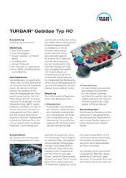
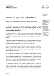
Examples on on equal sized <strong>LNG</strong> carriers based on the Membrane and the the Spherical (Moss) types types<br />
<strong>LNG</strong> is always carried/transported cold<br />
at atmospheric pressure, i.e. <strong>in</strong> its liquefied<br />
form at its boil<strong>in</strong>g po<strong>in</strong>t of as low<br />
as −163ºC. As previously mentioned, <strong>in</strong><br />
its liquid form, natural gas reduces its<br />
volume by 600 times and has a density<br />
of approx. 450 kg/m 3 . The <strong>LNG</strong> is<br />
always be<strong>in</strong>g refrigerated by means of<br />
its boil-off gas and, therefore, the <strong>LNG</strong><br />
tanks will normally not be completely<br />
emptied because some of the <strong>LNG</strong> still<br />
has to cool down the tanks.<br />
138,000<br />
138,000<br />
m<br />
m 3 3 <strong>LNG</strong> carrier<br />
of<br />
of<br />
the<br />
the membrane<br />
type<br />
type<br />
138,000 m 3 <strong>LNG</strong> carrier of the membrane type<br />
138,000 138,000 m 3 <strong>LNG</strong> m 3 <strong>LNG</strong> carrier of of the the spherical spherical (Moss) (Moss) type type<br />
138,000 m 3 <strong>LNG</strong> carrier of the spherical (Moss) type<br />
All liquefied gases carried <strong>in</strong> bulk must<br />
be carried on a gas carrier <strong>in</strong> accordance<br />
with the Gas Code rules of IMO<br />
(International Maritime Organisation).<br />
Fig. 1: Examples of equal-sized <strong>LNG</strong> carriers based on the membrane and the spherical (Moss) types<br />
shown <strong>in</strong> the same scale<br />
6 <strong>Propulsion</strong> <strong>Trends</strong> <strong>in</strong> <strong>LNG</strong> <strong>Carriers</strong>
are smaller than for a similar spherical<br />
(Moss) type <strong>LNG</strong> carrier, as also illustrated<br />
<strong>in</strong> Fig. 1, show<strong>in</strong>g the ships <strong>in</strong><br />
the same scale. However, the boil-off<br />
gas amount is higher for the membrane<br />
tank type compared to that of the<br />
spherical tank type.<br />
The membrane systems have been<br />
greatly improved s<strong>in</strong>ce the <strong>in</strong>troduction<br />
<strong>in</strong> 1969, and especially over the last<br />
decade, they have, after the improvements,<br />
proved their suitability for <strong>LNG</strong><br />
carriers.<br />
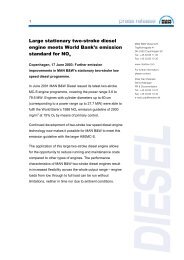
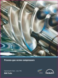
About 55% of the exist<strong>in</strong>g fleet <strong>in</strong> service<br />
(31 July 2007) consists of the membrane<br />
type, whereas about 80% of the<br />
<strong>LNG</strong> carriers on order today (31 July<br />
2007), <strong>in</strong> numbers, are based on the<br />
membrane types [3], see Fig. 2.<br />
The ma<strong>in</strong> ship particulars of <strong>LNG</strong> carriers<br />
analysed <strong>in</strong> this paper are based<br />
on the two, and almost only used, ma<strong>in</strong> capacity, of course, corresponds to<br />
groups of <strong>LNG</strong> carriers:<br />
a certa<strong>in</strong> deadweight tonnage, which<br />
normally, when referr<strong>in</strong>g to the design<br />
1. Spherical (Moss) conta<strong>in</strong>ment system draught, is of the magnitude of 0.47-<br />
2. Membrane conta<strong>in</strong>ment system 0.52 times the correspond<strong>in</strong>g size <strong>in</strong><br />
m 3 , and when referr<strong>in</strong>g to the scantl<strong>in</strong>g<br />
Size of the <strong>LNG</strong> carriers<br />
(max.) draught is of the magnitude of<br />
The deadweight of a ship is the carry<strong>in</strong>g<br />
capacity <strong>in</strong> metric tons (1,000 kg)<br />
0.52-0.58.<br />
<strong>in</strong>clud<strong>in</strong>g the weight of bunkers and Ship classes<br />
other supplies necessary for the ship’s As mentioned earlier, there is a split up<br />
propulsion. The maximum possible <strong>in</strong> <strong>LNG</strong> carriers, but this is based on<br />
deadweight tonnage of a tanker, for example,<br />
will normally be used as the size the cargo conta<strong>in</strong>ment system, as for<br />
the differences <strong>in</strong> the construction of<br />
of the tanker.<br />
example the spherical (Moss) and the<br />
membrane conta<strong>in</strong>ment systems.<br />
The size of an <strong>LNG</strong> carrier is, however,<br />
normally not based on its deadweight Depend<strong>in</strong>g on the ship size and particulars,<br />
the three ma<strong>in</strong> groups of mer-<br />
tonnage, but on its obta<strong>in</strong>able volumetric<br />
capacity of liquid natural gas <strong>in</strong> m 3 . chant ships, tankers, bulk carriers and<br />
conta<strong>in</strong>er vessels, are split <strong>in</strong>to different<br />
Depend<strong>in</strong>g on the density of the <strong>LNG</strong> ma<strong>in</strong> groups or classes, like handymax,<br />
and the ship size, the volumetric <strong>LNG</strong> panamax, etc.<br />
Distribution <strong>in</strong> conta<strong>in</strong>ment systems of <strong>LNG</strong> fleet<br />
Number of<br />
<strong>LNG</strong> carriers<br />
<strong>in</strong> %<br />
Exist<strong>in</strong>g <strong>LNG</strong> fleet<br />
80<br />
239 ships - 31 July 2007<br />
Ref.: <strong>LNG</strong> World Shipp<strong>in</strong>g Journal<br />
September/October 2007<br />
70<br />
<strong>LNG</strong> carriers on order<br />
136 ships - 31 July 2007<br />
80%<br />
60<br />
55%<br />
50<br />
40<br />
42%<br />
109<br />
30<br />
132<br />
20<br />
100<br />
17%<br />
10<br />
23<br />
0<br />
3%<br />
7<br />
Others<br />
Moss<br />
Membrane<br />
Conta<strong>in</strong>ment system<br />
3%<br />
4<br />
Others<br />
Moss<br />
Membrane<br />
Conta<strong>in</strong>ment system<br />
Fig. 2: Distribution <strong>in</strong> conta<strong>in</strong>ment systems on <strong>LNG</strong> fleet<br />
<strong>MAN</strong> B&W <strong>Diesel</strong><br />
<strong>Propulsion</strong> <strong>Trends</strong> <strong>in</strong> <strong>LNG</strong> <strong>Carriers</strong><br />
7
However, for <strong>LNG</strong> carriers, there is no<br />
such similar general split-up <strong>in</strong>to different<br />
groups or classes based on the dimensions<br />
alone. The reason is that ever<br />
s<strong>in</strong>ce 1962, <strong>LNG</strong> carriers have normally<br />
been designed for specific purposes/<br />
routes and <strong>LNG</strong> term<strong>in</strong>als (with the<br />
result<strong>in</strong>g limitations to the ship dimensions)<br />
<strong>in</strong> large series of the same size.<br />
Thus, the most common size of <strong>LNG</strong><br />
carriers delivered or on order is between<br />
120,000-180,000 m 3 , and often referred<br />
to as Conventional.<br />
The demand for lower <strong>LNG</strong> transportation<br />
costs is most effectively met by<br />
<strong>in</strong>creas<strong>in</strong>g the <strong>LNG</strong> capacity of the <strong>LNG</strong><br />
carriers. Thus, the <strong>LNG</strong> carriers to and<br />
from Qatar ordered over the last few<br />
years are of the large sizes of approx.<br />
210,000 m 3 and 265,000 m 3 , and referred<br />
to as Q-flex and Q-max, respectively.<br />
Thus, the <strong>LNG</strong> carrier classes often<br />
used today can therefore be referred to<br />
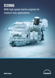
as listed <strong>in</strong> Table I and Fig. 3.<br />
<strong>LNG</strong> carrier classes Dimensions Ship size - <strong>LNG</strong> capacity<br />
Small<br />
Small Conventional<br />
Fig. 3: <strong>LNG</strong> carrier classes<br />
B:<br />
L OA :<br />
B:<br />
L OA :<br />
Large Conventional T des :<br />
B:<br />
L OA :<br />
Q-flex T des :<br />
B:<br />
L OA :<br />
Q-max T des :<br />
B:<br />
L OA :<br />
up to 40 m<br />
up to 250 m<br />
41 - 49 m<br />
270 - 298 m<br />
up to 12.0 m<br />
43 - 46 m<br />
285 - 295 m<br />
Examples of special <strong>LNG</strong> carrier sub-classes:<br />
up to 12.0 m<br />
approx. 50 m<br />
approx. 315 m<br />
up to 12.0 m<br />
53 - 55 m<br />
approx. 345 m<br />
Med-max (Mediterranean maximum size) about 75,000 m 3<br />
Atlantic-max (Atlantic sea maximum size) about 165,000 m 3<br />
Number of<br />
<strong>LNG</strong> carriers<br />
<strong>in</strong> %<br />
90<br />
80<br />
83%<br />
up to 90,000 m 3<br />
120,000 - 149,999 m 3<br />
150,000 - 180,000 m 3<br />
200,000 - 220,000 m 3<br />
more than 260,000 m 3<br />
<strong>LNG</strong> carrier fleet 31 July 2007 - 239 ships<br />
Ref.: Lloyd’s Register - Fairplay’s “PC-Register”<br />
Besides the ma<strong>in</strong> classes described for<br />
<strong>LNG</strong> carriers, special sub-classes are<br />
often used to describe the specialty of<br />
the ship <strong>in</strong> question, as for example the<br />
Med-max and Atlantic-max, see Fig. 3.<br />
<strong>LNG</strong> carrier market<br />
70<br />
60<br />
50<br />
40<br />
30<br />
198<br />
Small: Up to 90,000 m 3<br />
Small<br />
Conventional: 120,000-149,999 m 3<br />
Large<br />
Conventional: 150,000-180,000 m 3<br />
0<br />
Small<br />
Q-max: More than 260,000 m 3<br />
Q-flex: 200,000-220,000 m 3<br />
Small<br />
Conventional<br />
Table I: Ma<strong>in</strong> <strong>LNG</strong> classes<br />
20<br />
10<br />
15%<br />
36<br />
2%<br />
5<br />
Large<br />
Conventional<br />
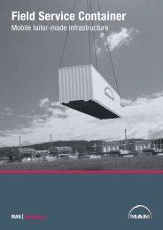
Fig. 4a: Distribution of exist<strong>in</strong>g <strong>LNG</strong> carriers <strong>in</strong> service (number of ships)<br />
0%<br />
Q-flex<br />
0%<br />
Q-max<br />
Classes<br />
8 <strong>Propulsion</strong> <strong>Trends</strong> <strong>in</strong> <strong>LNG</strong> <strong>Carriers</strong>
Distribution of <strong>LNG</strong> carriers on order (number of ships)<br />
The first <strong>LNG</strong> carrier with a capacity of<br />
150 m 3 was <strong>in</strong>troduced <strong>in</strong> 1962, and<br />
the second one of 27,400 m 3 <strong>in</strong> 1964,<br />
and s<strong>in</strong>ce the mid 1970s the maximum<br />
and commonly used <strong>LNG</strong> carrier size<br />
has been approx. 125,000-140,000 m 3<br />
for 30 years.<br />
However, recently there has been a<br />
dramatic <strong>in</strong>crease <strong>in</strong> the size of the<br />
<strong>LNG</strong> carriers ordered, with 266,000 m 3<br />
(Q-max) as the largest one (31 July 2007),<br />
but <strong>LNG</strong> carriers as large as 300,000 m 3 are<br />
now on the project stage. The reason<br />
for this is that the larger the <strong>LNG</strong> carrier,<br />
the lower the transportation costs.<br />
This <strong>in</strong>crease <strong>in</strong> ship size will also <strong>in</strong>volve<br />
design modifications of new <strong>LNG</strong><br />
plants and term<strong>in</strong>als. Today, the maximum<br />
loaded ship draught <strong>in</strong> service is<br />
still approx. 12 m, because of the limitations<br />
of the exist<strong>in</strong>g harbour facilities.<br />
Distribution of <strong>LNG</strong> carriers today<br />
As of 31 July 2007, the number of <strong>LNG</strong><br />
carriers on order is 136, correspond<strong>in</strong>g<br />
to about 57% of the exist<strong>in</strong>g fleet <strong>in</strong><br />
service (239), see Fig. 2.<br />
Fig. 4a shows the split-up <strong>in</strong> <strong>LNG</strong><br />
classes of the exist<strong>in</strong>g <strong>LNG</strong> carriers <strong>in</strong><br />
service. As can be seen, the current<br />
fleet is dom<strong>in</strong>ated by relatively small<br />
ships of the ‘‘Small’’ and ‘‘Small Conventional’’<br />
classes. Only 2% of the <strong>LNG</strong><br />
carrier fleet is larger than 150,000 m 3<br />
(Large Conventional).<br />
<strong>LNG</strong> carriers on order<br />
However, accord<strong>in</strong>g to Fig. 4b, which<br />
shows the <strong>LNG</strong> carriers on order as of<br />
31 July 2007, the distribution of the fleet<br />
on <strong>LNG</strong> classes will change drastically.<br />
Thus, the number of large <strong>LNG</strong> carriers<br />
ordered over the last three years has <strong>in</strong>-<br />
<strong>MAN</strong> B&W <strong>Diesel</strong><br />
Number of<br />
<strong>LNG</strong> carriers<br />
<strong>in</strong> %<br />
40<br />
35<br />
30<br />
25<br />
20<br />
15<br />
10<br />
5<br />
0<br />
5%<br />
7<br />
Small<br />
<strong>LNG</strong> carriers on order 31 July 2007 - 136 ships<br />
Ref.: Lloyd’s Register - Fairplay’s “PC-Register”<br />
26%<br />
36<br />
Small<br />
Conventional<br />
37%<br />
50<br />
Large<br />
Conventional<br />
Fig. 4b: Distribution of <strong>LNG</strong> carriers on order (number of ships)<br />
Number of <strong>LNG</strong><br />
carriers delivered<br />
60<br />
50<br />
40<br />
30<br />
20<br />
10<br />
0<br />
Q-max<br />
Q-flex<br />
Large Conventional<br />
Small Conventional<br />
Small<br />
Fig. 4c: Year of delivery of <strong>LNG</strong> carriers<br />
1990<br />
1991<br />
1992<br />
1993<br />
1994<br />
1995<br />
1996<br />
1997<br />
1998<br />
1999<br />
creased greatly dur<strong>in</strong>g this period.<br />
At the same time, the contract<strong>in</strong>g of<br />
“Small” ships has come to a complete<br />
standstill. On the other hand, some<br />
“Small Conventional” <strong>LNG</strong> carriers have<br />
been ordered as well, probably because<br />
of the application for a specific<br />
trade/route.<br />
23%<br />
31<br />
Q-flex<br />
<strong>LNG</strong> carrier fleet 31 July 2007<br />
Ref.: Lloyd’s Register - Fairplay’s “PC-Register”<br />
2000<br />
2001<br />
2002<br />
2003<br />
2004<br />
2005<br />
2006<br />
2007<br />
2008<br />
2009<br />
2010<br />
9%<br />
12<br />
Q-max<br />
Year of delivery<br />
Classes<br />
Fig. 4c shows, as <strong>in</strong>dicated <strong>in</strong> Fig. 4b,<br />
that large <strong>LNG</strong> carriers like the “Large<br />
Conventional” and Q-flex and Q-max<br />
will enter operation <strong>in</strong> the com<strong>in</strong>g years.<br />
Fig. 4d, which shows the average ship<br />
size of the ships delivered, also confirms<br />
that the average <strong>LNG</strong> size to be<br />
delivered will be larger <strong>in</strong> the future.<br />
<strong>Propulsion</strong> <strong>Trends</strong> <strong>in</strong> <strong>LNG</strong> <strong>Carriers</strong><br />
9
Average size of ship,<br />
<strong>LNG</strong> capacity<br />
m 3<br />
200,000<br />
<strong>LNG</strong> carrier fleet 31 July 2007<br />
Ref.: Lloyd’s Register - Fairplay’s “PC-Register”<br />
175,000<br />
150,000<br />
125,000<br />
100,000<br />
75,000<br />
Fig. 4d: Average size of <strong>LNG</strong> carriers delivered<br />
However, because many small <strong>LNG</strong><br />
carriers have also been ordered, the<br />
average <strong>LNG</strong> size may not be as high<br />
as expected.<br />
1990<br />
1991<br />
1992<br />
1993<br />
1994<br />
1995<br />
1996<br />
1997<br />
1998<br />
1999<br />
2000<br />
2001<br />
2002<br />
2003<br />
2004<br />
2005<br />
2006<br />
2007<br />
Number of<br />
<strong>LNG</strong> carriers<br />
on order, <strong>in</strong> %<br />
50<br />
2008<br />
2009<br />
2010<br />
Year of delivery<br />
Average of the<br />
2007 fleet<br />
Distribution of <strong>Propulsion</strong> Systems of <strong>LNG</strong> Fleet on order<br />
<strong>LNG</strong> carriers on order<br />
136 ships - 31 July 2007<br />
Ref.: <strong>LNG</strong> World Shipp<strong>in</strong>g Journal<br />
September/October 2007<br />
Until now, very few <strong>LNG</strong> carriers have<br />
40<br />
40%<br />
been scrapped.<br />
33%<br />
Distribution of propulsion systems<br />
on <strong>LNG</strong> carriers<br />
Of the ships on order as of 31 July<br />
2007, 33% are with two-stroke diesel<br />
eng<strong>in</strong>es and reliquefaction, 26% with<br />
diesel electric propulsion and 40% with<br />
steam turb<strong>in</strong>e propulsion [3], see Fig. 5a.<br />
30<br />
20<br />
10<br />
0<br />
55<br />
Steam<br />
turb<strong>in</strong>e<br />
45<br />
Two-stroke<br />
diesel and<br />
reliquefaction<br />
26%<br />
35<br />
<strong>Diesel</strong>electric<br />
1%<br />
1<br />
Others<br />
Fig. 5b shows the distribution of the<br />
propulsion systems chosen <strong>in</strong> the <strong>LNG</strong><br />
fleet delivered or on order as of 31 July<br />
2007, and shown as a function of year<br />
of delivery. This curve also confirms the<br />
emerg<strong>in</strong>g shift from steam turb<strong>in</strong>e to<br />
diesel.<br />
Fig. 5a: Distribution of propulsion systems of <strong>LNG</strong> fleet on order<br />
10 <strong>Propulsion</strong> <strong>Trends</strong> <strong>in</strong> <strong>LNG</strong> <strong>Carriers</strong>
Number of<br />
ships per year<br />
60<br />
50<br />
40<br />
30<br />
<strong>LNG</strong> carrier fleet<br />
Delivered or on order 31 July 2007<br />
Two-stroke diesel<br />
<strong>Diesel</strong>-Electric<br />
Steam turb<strong>in</strong>e<br />
Average Ship Particulars as a<br />
Function of Ship Size<br />
On the basis of <strong>LNG</strong> carriers built or<br />
contracted <strong>in</strong> the period 1997-2007, as<br />
reported <strong>in</strong> the Lloyd’s Register – Fairplay’s<br />
“PC-Register”, we have estimated<br />
the average ship particulars of the<br />
different sizes of <strong>LNG</strong> carriers based on<br />
the spherical (Moss) and the membrane<br />
conta<strong>in</strong>ment systems, respectively.<br />
20<br />
10<br />
0<br />
1965 1970 1975 1980 1985 1990 1995 2000 2005 2010<br />
Year of delivery<br />
Fig. 5b: Distribution of propulsion systems of <strong>LNG</strong> fleet <strong>in</strong> year of delivery<br />
Average Hull Design Factor of <strong>LNG</strong> <strong>Carriers</strong> (Membrane Type)<br />
Average hull<br />
design factor, F des<br />
1.5<br />
1.4<br />
1.3<br />
1.2<br />
1.1<br />
1.0<br />
0.9<br />
0.8<br />
0.7<br />
Ma<strong>in</strong> ship particulars<br />
0.6<br />
L pp<br />
: Length between perpendiculars (m)<br />
0.5<br />
B : Breadth (m)<br />
D<br />
0.4<br />
scant<br />
: Scantl<strong>in</strong>g draught (m)<br />
Q : <strong>LNG</strong> capacity (m 3 )<br />
0.3<br />
F des<br />
: Average hull design factor<br />
0.2<br />
F<br />
0.1<br />
des<br />
= L pp<br />
x B x D scant<br />
/Q<br />
0<br />
0 50,000 100,000 150,000 200,000 250,000 300,000 m 3<br />
Size of ship, <strong>LNG</strong> capacity<br />
Fig. 6: Average hull design factor of <strong>LNG</strong> carriers (membrane type)<br />
However, as only very few <strong>LNG</strong> carriers<br />
of some ship sizes have been built <strong>in</strong><br />
this period, for these ship types, it has<br />
also been necessary to look back to the<br />
time before 1997.<br />
Average hull design factor, F des<br />
Based on the above statistical material,<br />
the average design relationship between<br />
the ship particulars of the <strong>LNG</strong><br />
carriers can, as an <strong>in</strong>dication, be expressed<br />
by means of the average hull<br />
design factor, F des , see below and Fig. 6:<br />
F des = L PP x B x D scant /Q<br />
where<br />
L PP : length between perpendiculars (m)<br />
B: ship breadth (m)<br />
D scant : scantl<strong>in</strong>g draught (max.) (m)<br />
Q: <strong>LNG</strong> capacity (max.) of ship (m 3 )<br />
Based on the above design factor Fdes,<br />
any miss<strong>in</strong>g particular can approximately<br />
be found as:<br />
L PP = F des x Q/(B x D scant ) m<br />
B = F des x Q/(L PP x D scant ) m<br />
D scant = F des x Q/(L PP x B)<br />
m<br />
Q = L PP x B x D scant /F des m 3<br />
<strong>MAN</strong> B&W <strong>Diesel</strong><br />
<strong>Propulsion</strong> <strong>Trends</strong> <strong>in</strong> <strong>LNG</strong> <strong>Carriers</strong><br />
11
Length between<br />
perpendiculars<br />
m<br />
400<br />
300<br />
200<br />
100<br />
Small<br />
Spherical (Moss)<br />
Small<br />
Conventional<br />
Large<br />
Conventional<br />
Membrane<br />
Q-flex<br />
Q-max<br />
0<br />
0 50,000 100,000 150,000 200,000 250,000 300,000 m 3<br />
Size of ship, <strong>LNG</strong> capacity<br />
Fig. 7: Average length between perpendiculars of <strong>LNG</strong> carriers (membrane and Moss types)<br />
In Figs. 7, 8 and 9, the first three ship<br />
particulars are shown as a function of<br />
the ship size <strong>in</strong> <strong>LNG</strong> capacity (Q). The<br />
ma<strong>in</strong> groups of <strong>LNG</strong> carrier classes are<br />
also shown.<br />
The ship particulars of the Moss type<br />
ships are only shown up to about<br />
150,000 m 3 as be<strong>in</strong>g the largest one<br />
built of this conta<strong>in</strong>ment type.<br />
Average design ship speed<br />
In Fig. 10, the average ship speed V des ,<br />
used for design of the propulsion system<br />
and valid for the design draught of<br />
the ship, is shown as a function of the<br />
ship size. The design draught is normally<br />
from 5% to 10% lower than the<br />
scantl<strong>in</strong>g draught (max. draught) used<br />
for calculations of the hull strength.<br />
Breadth<br />
m<br />
60<br />
50<br />
40<br />
Small<br />
Spherical (Moss)<br />
Small<br />
Conventional<br />
Large<br />
Conventional<br />
Membrane<br />
Q-flex<br />
Q-max<br />
The larger the <strong>LNG</strong> capacity of the ships,<br />
the higher the ship speed, and today the<br />
average design ship speed is about 20<br />
knots for ships larger than 150,000 m 3 .<br />
30<br />
20<br />
10<br />
0<br />
0 50,000 100,000 150,000 200,000 250,000 300,000 m 3<br />
Size of ship, <strong>LNG</strong> capacity<br />
Fig. 8: Average ship breadth (beam) of <strong>LNG</strong> carriers (membrane and Moss types)<br />
12 <strong>Propulsion</strong> <strong>Trends</strong> <strong>in</strong> <strong>LNG</strong> <strong>Carriers</strong>
Design draught<br />
m<br />
14<br />
13<br />
12<br />
11<br />
10<br />
9<br />
8<br />
7<br />
6<br />
5<br />
4<br />
3<br />
2<br />
1<br />
Small<br />
Spherical (Moss)<br />
Membrane<br />
Small<br />
Conventional<br />
Large<br />
Conventional<br />
Q-flex<br />
Q-max<br />
0<br />
0 50,000 100,000 150,000 200,000 250,000 300,000 m 3<br />
Size of ship, <strong>LNG</strong> capacity<br />
Fig. 9: Average design draught of <strong>LNG</strong> carriers (membrane and Moss types)<br />
Average design<br />
ship speed<br />
knots<br />
22<br />
Large<br />
Conventional<br />
Q-flex<br />
Q-max<br />
20<br />
Small<br />
Conventional<br />
18<br />
Small<br />
16<br />
14<br />
12<br />
10<br />
0 50,000 100,000 150,000 200,000 250,000 300,000 m 3<br />
Size of ship, <strong>LNG</strong> capacity<br />
Fig. 10: Average design ship speed of <strong>LNG</strong> carriers<br />
<strong>MAN</strong> B&W <strong>Diesel</strong><br />
<strong>Propulsion</strong> <strong>Trends</strong> <strong>in</strong> <strong>LNG</strong> <strong>Carriers</strong><br />
13
<strong>Propulsion</strong> Power Demand as a<br />
Function of Ship Size<br />
Average <strong>LNG</strong> carriers<br />
Based on the average ship particulars<br />
and ship speeds already described for<br />
<strong>LNG</strong> carriers built or contracted <strong>in</strong> the<br />
period of 1997-2007, we have made a<br />
power prediction calculation (Holtrop &<br />
Mennen’s Method) for such <strong>LNG</strong> carriers<br />
<strong>in</strong> various sizes from 19,000 m 3<br />
to 265,000 m 3 . However, as the membrane<br />
type <strong>LNG</strong> carrier seems to become<br />
the dom<strong>in</strong>at<strong>in</strong>g type <strong>in</strong> the future,<br />
cf. Fig. 2, a power prediction has only been<br />
made for <strong>LNG</strong> carriers of this type.<br />
For all cases, we have assumed a sea<br />
marg<strong>in</strong> of 15% and an eng<strong>in</strong>e marg<strong>in</strong><br />
of 10%, i.e. a service rat<strong>in</strong>g of 90%<br />
SMCR, <strong>in</strong>clud<strong>in</strong>g 15% sea marg<strong>in</strong>.<br />
Furthermore, the size of the propeller<br />
diameter is assumed to be as high<br />
as up to approx. 76% of the design<br />
draught, because the ships are normally<br />
sail<strong>in</strong>g with a big draught also <strong>in</strong><br />
ballast conditions (low density cargo).<br />
The average ship particulars of these<br />
<strong>LNG</strong> carriers are shown <strong>in</strong> the tables<br />
<strong>in</strong> Fig. 11, and Figs 12 and 13 valid<br />
for <strong>LNG</strong> capacity 19,000-138,000 m 3<br />
and 150,000-265,000 m 3 , respectively.<br />
On this basis, and valid for the design<br />
draught and design ship speed, we<br />
have calculated the specified eng<strong>in</strong>e<br />
MCR power needed for propulsion.<br />
The maximum design draught for the<br />
large <strong>LNG</strong> carriers <strong>in</strong> service is limited<br />
to about 12.0 m because of harbour facilities.<br />
This results <strong>in</strong> beam/design draught<br />
ratios be<strong>in</strong>g relatively high (above 4.0).<br />
In such a case, a tw<strong>in</strong>-skeg/tw<strong>in</strong>-screw<br />
solution will be an attractive alternative<br />
to the standard s<strong>in</strong>gle-screw solution,<br />
as a potential reduction of the propulsion<br />
power up to 9% is possible.<br />
Therefore, the large <strong>LNG</strong> carriers, besides<br />
the s<strong>in</strong>gle-screw version, see Fig. 12,<br />
have also been calculated for the tw<strong>in</strong>skeg/tw<strong>in</strong>-screw<br />
solution, see Fig. 13.<br />
The tw<strong>in</strong>-skeg/tw<strong>in</strong> ma<strong>in</strong> eng<strong>in</strong>e <strong>LNG</strong><br />
carrier would also meet the safety demands<br />
of the future to <strong>in</strong>stall at least<br />
double propulsion drives enhanc<strong>in</strong>g the<br />
redundancy of the prime movers.<br />
In fact, the Q-flex and Q-max ships<br />
have only been made/ordered <strong>in</strong> the<br />
tw<strong>in</strong>-skeg/tw<strong>in</strong>-screw version.<br />
Membrane Type Small Small Small<br />
S<strong>in</strong>gle-Screw (Med-max) Conventional<br />
Ship size, <strong>LNG</strong> capacity m 3 19,000 75,000 138,000<br />
Scantl<strong>in</strong>g draught<br />
Length overall<br />
Length between pp<br />
Breadth<br />
Design draught<br />
Sea marg<strong>in</strong><br />
Eng<strong>in</strong>e marg<strong>in</strong><br />
m 7.1 10.6 12.0<br />
m 130.0 220.0 276.0<br />
m 124.0 210.0 263.0<br />
m 25.6 35.0 43.4<br />
m 6.5 9.7 11.3<br />
% 15 15 15<br />
% 10 10 10<br />
Average design ship speed<br />
SMCR power<br />
Ma<strong>in</strong> eng<strong>in</strong>e options<br />
Average design ship speed - 0.5 kn<br />
SMCR power<br />
Ma<strong>in</strong> eng<strong>in</strong>e options<br />
Knots 15.0 17.5 19.5<br />
kW<br />
5,300 14,200 28,000<br />
1. 5S40ME-B9 6S60ME-C8 7K80ME-C9<br />
2. 5S42MC7 7S60ME-C7 6K90ME-C9<br />
3. 7S35ME-B9 5L70ME-C7 8K80ME-C6<br />
4. 5S65ME-C8 6K90ME9<br />
Knots 14.5 17.0 19.0<br />
kW 4,600 12,800 25,500<br />
1. 5S40ME-B9 6S60ME-C7 6K80ME-C9<br />
2. 5S42MC7 5L70ME-C7 6K90ME-C6<br />
3. 6S35ME-B9 5S65ME-C8 8L70ME-C8<br />
4. 8S70ME-C8<br />
Average design ship speed + 0.5 kn Knots 15.5 18.0 20.0<br />
SMCR power<br />
Ma<strong>in</strong> eng<strong>in</strong>e options<br />
KW<br />
1.<br />
6,150<br />
6S40ME-B9<br />
15,900<br />
7S60ME-C7<br />
30,800<br />
7K80ME-C9<br />
2. 6S42MC7 5L70ME-C8 6K90ME-C9<br />
3. 8S35ME-B9 6L70ME-C7 7K90ME-C6<br />
4. 6S65ME-C8 6K90ME9<br />
Fig. 11: Ship particulars and propulsion SMCR power demand (membrane type), <strong>LNG</strong> capacity 19,000-138,000 m 3 , s<strong>in</strong>gle-screw<br />
14 <strong>Propulsion</strong> <strong>Trends</strong> <strong>in</strong> <strong>LNG</strong> <strong>Carriers</strong>
Membrane Type Large Q-flex Q-max<br />
S<strong>in</strong>gle-Screw<br />
Conventional<br />
Ship size, <strong>LNG</strong> capacity m 3 150,000 210,000 265,000<br />
Scantl<strong>in</strong>g draught<br />
Length overall<br />
Length between pp<br />
Breadth<br />
Design draught<br />
Sea marg<strong>in</strong><br />
Eng<strong>in</strong>e marg<strong>in</strong><br />
Average design ship speed<br />
SMCR power<br />
Ma<strong>in</strong> eng<strong>in</strong>e options<br />
m 12.3 12.7 12.7<br />
m 288.0 315.0 345.0<br />
m 275.0 303.0 332.0<br />
m 44.2 50.0 54.0<br />
m 11.6 12.0 12.0<br />
% 15 15 15<br />
% 10 10 10<br />
Knots 20.0 20.0 20.0<br />
kW 31,400 39,300 45,200<br />
1. 6K90ME9 7K90ME9 8K90ME9<br />
2. 7K98ME7 8K98ME6<br />
3. 8K98ME7<br />
4.<br />
Average design ship speed - 0.5 kn Knots 19.5 19.5 19.5<br />
SMCR power<br />
Ma<strong>in</strong> eng<strong>in</strong>e options<br />
kW<br />
1.<br />
2.<br />
28,500<br />
6K90ME9<br />
35,700<br />
7K90ME9<br />
6K98ME7<br />
41,100<br />
8K90ME9<br />
7K98ME7<br />
3. 8K98ME6<br />
4.<br />
Average design ship speed + 0.5 kn Knots 20.5 20.5 20.5<br />
SMCR power<br />
Ma<strong>in</strong> eng<strong>in</strong>e options<br />
kW<br />
1.<br />
34,300<br />
6K90ME9<br />
43,200<br />
8K90ME9<br />
49,600<br />
9K90ME9<br />
2. 7K98ME7 9K98ME6<br />
3. 9K98ME7<br />
4.<br />
All above ME eng<strong>in</strong>es can also be delivered <strong>in</strong> ME-GI version (gas <strong>in</strong>jected)<br />
The SMCR power results are also<br />
shown <strong>in</strong> the tables <strong>in</strong> Figs. 11-13 ‘‘Ship<br />
Particulars and <strong>Propulsion</strong> SMCR Power<br />
Demand’’ together with the selected<br />
ma<strong>in</strong> eng<strong>in</strong>e options of the <strong>MAN</strong> B&W<br />
two-stroke eng<strong>in</strong>e types. The similar results<br />
valid for +/- 0.5 knots compared<br />
to the average design ship speed are<br />
also shown.<br />
Fig. 12: Ship particulars and propulsion SMCR power demand (membrane type), <strong>LNG</strong> capacity 150,000-265,000 m 3 , s<strong>in</strong>gle-screw<br />
Membrane Type Large Q-flex Q-max<br />
Tw<strong>in</strong>-Screw<br />
Conventional<br />
Ship size, <strong>LNG</strong> capacity m 3 150,000 210,000 265,000<br />
Scantl<strong>in</strong>g draught<br />
Length overall<br />
Length between pp<br />
Breadth<br />
Design draught<br />
Sea marg<strong>in</strong><br />
Eng<strong>in</strong>e marg<strong>in</strong><br />
m 12.3 12.7 12.7<br />
m 288.0 315.0 345.0<br />
m 275.0 303.0 332.0<br />
m 44.2 50.0 54.0<br />
m 11.6 12.0 12.0<br />
% 15 15 15<br />
% 10 10 10<br />
Average design ship speed<br />
SMCR power<br />
Ma<strong>in</strong> eng<strong>in</strong>e options<br />
Average design ship speed - 0.5 kn<br />
SMCR power<br />
Ma<strong>in</strong> eng<strong>in</strong>e options<br />
Knots 20.0 20.0 20.0<br />
kW 2x14,900 2x18,300 2x20,800<br />
1. 2x5S70ME-C7 2x6S70ME-C7 2x7S70ME-C7<br />
2. 2x6S65ME-C8 2x7S65ME-C8 2x8S65ME-C8<br />
3.<br />
4.<br />
Knots 19.5 19.5 19.5<br />
kW 2x13,600 2x16,700 2x19,000<br />
1. 2x5S70ME-C7 2x6S70ME-C7 2x6S70ME-C8<br />
2. 2x5S65ME-C8 2x6S65ME-C8 2x7S65ME-C8<br />
3.<br />
4.<br />
Average design ship speed + 0.5 kn Knots 20.5 20.5 20.5<br />
SMCR power<br />
Ma<strong>in</strong> eng<strong>in</strong>e options<br />
kW<br />
1.<br />
2x16,300<br />
2x5S70ME-C8<br />
2x20,100<br />
2x7S70ME-C7<br />
2x22,800<br />
2x7S70ME-C8<br />
2. 2x6S70ME-C7 2x7S65ME-C8 2x8S65ME-C8<br />
3. 2x6S65ME-C8<br />
4.<br />
All above ME eng<strong>in</strong>es can also be delivered <strong>in</strong> ME-GI version (gas <strong>in</strong>jected)<br />
Fig. 13: Ship particulars and propulsion SMCR power demand (membrane type), <strong>LNG</strong> capacity 150,000-265,000 m3, tw<strong>in</strong>-skeg and tw<strong>in</strong>-screw<br />
<strong>MAN</strong> B&W <strong>Diesel</strong><br />
<strong>Propulsion</strong> <strong>Trends</strong> <strong>in</strong> <strong>LNG</strong> <strong>Carriers</strong><br />
15
<strong>Propulsion</strong> Power Demand of Average<br />
<strong>LNG</strong> <strong>Carriers</strong> as a Function of Ship<br />
Speed<br />
When the required ship speed is<br />
changed, the required SMCR power<br />
will change too, as mentioned above,<br />
and other ma<strong>in</strong> eng<strong>in</strong>e options could<br />
be selected. This trend – with the average<br />
ship particulars and average ship<br />
speed as the basis – is shown <strong>in</strong> detail<br />
<strong>in</strong> Figs. 14 and 15 for s<strong>in</strong>gle-screw vessels,<br />
and <strong>in</strong> Fig. 16 for large tw<strong>in</strong>-skeg/<br />
tw<strong>in</strong>-screw vessels.<br />
It is possible to derate the eng<strong>in</strong>e, i.e.<br />
use an SMCR power lower than the<br />
nom<strong>in</strong>al MCR power, if the nom<strong>in</strong>al<br />
MCR power needed for a given ma<strong>in</strong><br />
eng<strong>in</strong>e is too high for a required ship<br />
speed. This would also result <strong>in</strong> a lower<br />
specific fuel consumption of the eng<strong>in</strong>e.<br />
Therefore, <strong>in</strong> some cases it could be of<br />
particular advantage, consider<strong>in</strong>g the<br />
high fuel price today, to select a higher<br />
mark number than needed and derate<br />
the eng<strong>in</strong>e.<br />
SMCR power<br />
kW<br />
40,000<br />
Includ<strong>in</strong>g:<br />
15% sea marg<strong>in</strong><br />
10% eng<strong>in</strong>e marg<strong>in</strong><br />
Small<br />
Conventional<br />
21.0 kn<br />
7K90ME9/ME-C9<br />
20.5 kn<br />
8K80ME-C9<br />
6K90ME9/ME-C9<br />
30,000<br />
20,000<br />
Small<br />
7S60ME-C8<br />
5L70ME-C7<br />
6S60ME-C8<br />
6L70ME-C8<br />
7L70ME-C8<br />
8L70ME-C8<br />
Average design<br />
ship speed<br />
16.5 kn<br />
17.0 kn<br />
18.0 kn<br />
17.5 kn 6S65ME-C8<br />
5S65ME-C8<br />
20.0 kn<br />
19.5 kn<br />
19.0 kn<br />
18.5 kn<br />
7S70ME-C8<br />
6K80ME-C6<br />
7K80ME-C9<br />
6K80ME-C9<br />
8S70ME-C8<br />
10,000<br />
7S40ME-B9<br />
6S40ME-B9<br />
5S40ME-B9<br />
5S35ME-B9<br />
5S60ME-C7<br />
15.0 kn<br />
14.5 kn<br />
14.0 kn<br />
15.5 kn<br />
16.0 kn<br />
0<br />
0 50,000<br />
100,000<br />
150,000 m 3<br />
Size of ship, <strong>LNG</strong> capacity<br />
Fig. 14: <strong>Propulsion</strong> SMCR power demand of an average <strong>LNG</strong> carrier (membrane type), Small and Small Conventional – s<strong>in</strong>gle-screw<br />
16 <strong>Propulsion</strong> <strong>Trends</strong> <strong>in</strong> <strong>LNG</strong> <strong>Carriers</strong>
SMCR power<br />
kW<br />
70,000<br />
60,000<br />
Includ<strong>in</strong>g:<br />
15% sea marg<strong>in</strong><br />
10% eng<strong>in</strong>e marg<strong>in</strong><br />
Large<br />
Conventional<br />
Q-flex<br />
Q-max<br />
21.0 kn<br />
10K98ME7<br />
9K98ME7<br />
50,000<br />
40,000<br />
9K90ME9<br />
8K90ME9<br />
7K90ME9<br />
Average design ship speed<br />
20.5 kn<br />
20.0 kn<br />
19.5 kn<br />
19.0 kn<br />
8K98ME7<br />
7K98ME7<br />
7K98ME6<br />
30,000<br />
20,000<br />
6K90ME9<br />
7K80ME-C9<br />
5K90ME9<br />
8S70ME-C8<br />
7S70ME-C8<br />
6K98ME6<br />
10,000<br />
All above eng<strong>in</strong>es can<br />
also be delivered <strong>in</strong> ME-GI<br />
version (gas <strong>in</strong>jected)<br />
0<br />
100,000 150,000<br />
200,000<br />
250,000<br />
300,000 m 3<br />
Size of ship, <strong>LNG</strong> capacity<br />
<strong>Propulsion</strong> SMCR Power Demand of an Average <strong>LNG</strong> Carrier (Membrane Type)<br />
Large Conventional, Q-flex and Q-max - Tw<strong>in</strong> Screw<br />
Fig.15: <strong>Propulsion</strong> SMCR power demand of an average <strong>LNG</strong> carrier (membrane type), Large Conventional, Q-flex and Q-max – s<strong>in</strong>gle-screw<br />
Total SMCR power<br />
kW<br />
60,000<br />
Includ<strong>in</strong>g:<br />
15% sea marg<strong>in</strong><br />
10% eng<strong>in</strong>e marg<strong>in</strong><br />
50,000<br />
Large<br />
Conventional<br />
Q-flex<br />
Q-max<br />
21.0 kn 2 x 8S70ME-C8<br />
2 x 8S70ME-C7<br />
20.5 kn<br />
8S65ME-C8<br />
2 x 7S70ME-C8<br />
20.0 kn 2 x 7S70ME-C7<br />
40,000<br />
30,000<br />
2 x 6S70ME-C8<br />
2 x 6S70ME-C7<br />
2 x 6S65ME-C8<br />
2 x 5S70ME-C8<br />
2 x 5S70ME-C7<br />
2 x 5S65ME-C8<br />
Average design ship speed<br />
19.5 kn<br />
19.0 kn<br />
2 x 7S65ME-C8<br />
20,000<br />
10,000<br />
0<br />
All above eng<strong>in</strong>es can<br />
also be delivered <strong>in</strong> ME-GI<br />
version (gas <strong>in</strong>jected)<br />
100,000 150,000<br />
200,000<br />
250,000<br />
300,000 m 3<br />
Size of ship, <strong>LNG</strong> capacity<br />
Fig. 16: <strong>Propulsion</strong> SMCR power demand of an average <strong>LNG</strong> carrier (membrane type), Large Conventional, Q-flex and Q-max – tw<strong>in</strong>-skeg and tw<strong>in</strong>-screw<br />
<strong>MAN</strong> B&W <strong>Diesel</strong><br />
<strong>Propulsion</strong> <strong>Trends</strong> <strong>in</strong> <strong>LNG</strong> <strong>Carriers</strong><br />
17
Summary<br />
Safety and reliability of <strong>LNG</strong> carriers<br />
have always been important demands<br />
to the design of this type of ship, as can<br />
also be seen from the str<strong>in</strong>gent standards<br />
given by IMO and several countries.<br />
Thus, the most widely used <strong>LNG</strong><br />
conta<strong>in</strong>ment systems – the Moss and<br />
the membrane – have been applied for<br />
many years because of their reliability.<br />
Today, the membrane type <strong>LNG</strong> carrier<br />
seems to take over the major market<br />
share because of its better utilisation of<br />
the ship’s hull volume.<br />
For many years the steam turb<strong>in</strong>es<br />
have almost exclusively been used as<br />
prime movers for <strong>LNG</strong> carriers, even<br />
though its efficiency is much lower than<br />
e.g. directly coupled two-stroke diesel<br />
eng<strong>in</strong>es. The reason is the simplicity of<br />
utilis<strong>in</strong>g the boil-off gas <strong>in</strong> steam boilers<br />
to produce steam for steam turb<strong>in</strong>es.<br />
However, with the <strong>in</strong>troduction of the<br />
reliquefaction plant and/or gas-driven<br />
diesel eng<strong>in</strong>es some few years ago, it is<br />
today also possible to <strong>in</strong>stall high-efficiency<br />
diesel eng<strong>in</strong>es as prime movers,<br />
and thereby cut the fuel costs [4].<br />
The <strong>LNG</strong> carrier market is an <strong>in</strong>creas<strong>in</strong>gly<br />
important and attractive transport<br />
segment which, due to the <strong>in</strong>creas<strong>in</strong>g<br />
global demand to “clean” fuel, is expected<br />
to become of even greater importance<br />
<strong>in</strong> the future. Thus, the CO 2<br />
emission by burn<strong>in</strong>g <strong>LNG</strong> is about 23%<br />
lower than for heavy fuel oil.<br />
As described, <strong>MAN</strong> B&W eng<strong>in</strong>es are<br />
able to meet the eng<strong>in</strong>e power needs<br />
of any size <strong>in</strong> the modern <strong>LNG</strong> carrier<br />
fleet.<br />
It should be noted that today the alternative<br />
Compressed Natural Gas (CNG)<br />
transportation form has potential to<br />
match the <strong>LNG</strong> transportation form for<br />
shorter routes. Is now be<strong>in</strong>g <strong>in</strong>vestigated,<br />
but has so far not yet been materialised<br />
<strong>in</strong> a ship, even though there<br />
are some projects with CNG carriers.<br />
CNG’s gas density is about 2/3 of <strong>LNG</strong><br />
[5]. The advantage of CNG is that, <strong>in</strong><br />
contrast to <strong>LNG</strong>, CNG does not need<br />
any costly process<strong>in</strong>g plants to offload<br />
the gas. The tanks have to be of the cyl<strong>in</strong>drical<br />
pressure types or of the coselle<br />
type, i.e. of the coil/carousel type. Also<br />
for this ship type, the <strong>MAN</strong> B&W twostroke<br />
diesel eng<strong>in</strong>es are feasible.<br />
References<br />
[1] Introduction to <strong>LNG</strong> Center for<br />
Energy Economics<br />
The University of Texas at Aust<strong>in</strong><br />
January 2007<br />
[2] Liquefied Gas Handl<strong>in</strong>g Pr<strong>in</strong>ciples<br />
on Ships and <strong>in</strong> Term<strong>in</strong>als<br />
McGuire and White Witherby &<br />
Company Limited, London<br />
Third Edition 2000<br />
[3] <strong>LNG</strong> World Shipp<strong>in</strong>g Journal<br />
September/October 2007<br />
[4] <strong>LNG</strong> <strong>Carriers</strong><br />
ME-GI Eng<strong>in</strong>e with High Pressure<br />
Gas Supply System<br />
<strong>MAN</strong> <strong>Diesel</strong> A/S, Copenhagen,<br />
Denmark, January 2007<br />
[5] The Trans Ocean Gas<br />
CNG Transportation<br />
Technical & Bus<strong>in</strong>ess<br />
Development Plan<br />
Trans Ocean Gas Inc.<br />
April 2004<br />
18 <strong>Propulsion</strong> <strong>Trends</strong> <strong>in</strong> <strong>LNG</strong> <strong>Carriers</strong>
<strong>MAN</strong> B&W <strong>Diesel</strong><br />
<strong>Propulsion</strong> <strong>Trends</strong> <strong>in</strong> <strong>LNG</strong> <strong>Carriers</strong><br />
19
Copyright © <strong>MAN</strong> <strong>Diesel</strong> · Subject to modification <strong>in</strong> the <strong>in</strong>terest of technical progress. · 5510-0035-01ppr Aug 2009 · Pr<strong>in</strong>ted <strong>in</strong> Denmark<br />
<strong>MAN</strong> <strong>Diesel</strong><br />
Teglholmsgade 41, 2450<br />
Copenhagen, Denmark<br />
Phone +45 33 85 11 00<br />
Fax +45 33 85 10 30<br />
mandiesel-cph@mandiesel.com<br />
www.mandiesel.com