SPRING 2011
Distributor's Link Magazine Spring Issue 2011 / VOL 34 / NO.2
Distributor's Link Magazine Spring Issue 2011 / VOL 34 / NO.2

Create successful ePaper yourself
Turn your PDF publications into a flip-book with our unique Google optimized e-Paper software.
86 THE DISTRIBUTOR’S LINK<br />
TIGHTENING STRATEGIES FOR BOLTED JOINTS - Methods for Controlling and Analyzing Tightening continued from page 62<br />
After the yield load is reached, the clamping force will<br />
continue to increase in proportion to the increase in<br />
torque. In the elastic tightening zone, tension is<br />
proportional to the angle-of-turn from the elastic origin<br />
located on the torque-angle signature. When tightening<br />
beyond the yield point, the clamp force can be estimated<br />
by the procedure illustrated in Figure 8.<br />
The tangent line to the elastic straight-line tightening<br />
section of the signature is projected beyond the yield<br />
point and the final torque value is projected to the<br />
tangent line. The angle-of-turn from the elastic origin to<br />
the intercept of the backward projection from the final<br />
torque can be used to estimate the tension. This<br />
procedure can be seen as related to the strain-hardening<br />
phenomena observed when working materials beyond<br />
the yield point.<br />
where:<br />
AS N = Stress area of the nut<br />
L e = Effective grip length of the fastener<br />
D 2 = Pitch diameter<br />
D 3 = Root diameter<br />
After the material is first loaded beyond yield, Y1, the<br />
yield point is found to be at a higher level, Y2, on the<br />
next tightening cycle. After yielding, when the load is<br />
released, the release curve is offset and parallel to the<br />
elastic tightening curve.<br />
6. Thread Strip<br />
In general, a properly designed bolted joint will not<br />
fail by stripping of the threads either during installation<br />
or if the assembly is overloaded in tension. As a matter<br />
of good design practice, failure should always be due to<br />
fracture of the bolt.<br />
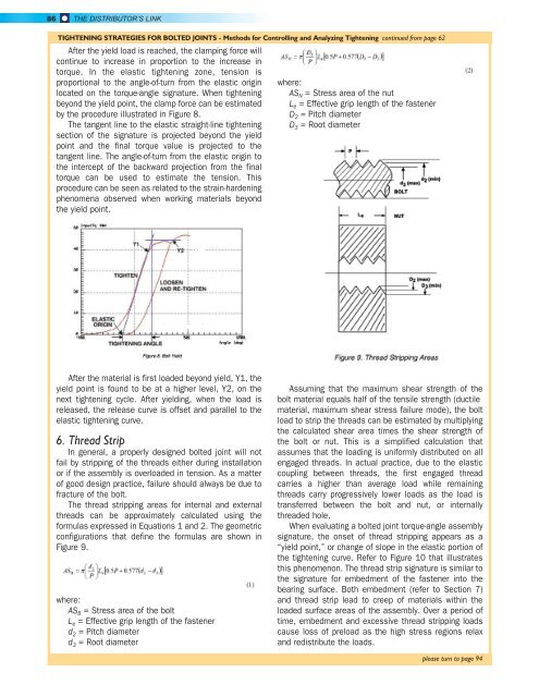
The thread stripping areas for internal and external<br />
threads can be approximately calculated using the<br />
formulas expressed in Equations 1 and 2. The geometric<br />
configurations that define the formulas are shown in<br />
Figure 9.<br />
where:<br />
AS B = Stress area of the bolt<br />
L e = Effective grip length of the fastener<br />
d 2 = Pitch diameter<br />
d 3 = Root diameter<br />
Assuming that the maximum shear strength of the<br />
bolt material equals half of the tensile strength (ductile<br />
material, maximum shear stress failure mode), the bolt<br />
load to strip the threads can be estimated by multiplying<br />
the calculated shear area times the shear strength of<br />
the bolt or nut. This is a simplified calculation that<br />
assumes that the loading is uniformly distributed on all<br />
engaged threads. In actual practice, due to the elastic<br />
coupling between threads, the first engaged thread<br />
carries a higher than average load while remaining<br />
threads carry progressively lower loads as the load is<br />
transferred between the bolt and nut, or internally<br />
threaded hole.<br />
When evaluating a bolted joint torque-angle assembly<br />
signature, the onset of thread stripping appears as a<br />
“yield point,” or change of slope in the elastic portion of<br />
the tightening curve. Refer to Figure 10 that illustrates<br />
this phenomenon. The thread strip signature is similar to<br />
the signature for embedment of the fastener into the<br />
bearing surface. Both embedment (refer to Section 7)<br />
and thread strip lead to creep of materials within the<br />
loaded surface areas of the assembly. Over a period of<br />
time, embedment and excessive thread stripping loads<br />
cause loss of preload as the high stress regions relax<br />
and redistribute the loads.<br />
please turn to page 94