Section 4.9 - Dry Swales - Sustainable Technologies Evaluation ...
Section 4.9 - Dry Swales - Sustainable Technologies Evaluation ...
Section 4.9 - Dry Swales - Sustainable Technologies Evaluation ...

Create successful ePaper yourself
Turn your PDF publications into a flip-book with our unique Google optimized e-Paper software.
Low Impact Development Stormwater Management Planning and Design Guide<br />
<strong>4.9</strong> <strong>Dry</strong> <strong>Swales</strong><br />
<strong>4.9</strong>.1 Overview<br />
Description<br />
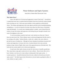
A dry swale can be thought of as an enhanced grass swale that incorporates an<br />
engineered soil (i.e., filter media or growing media) bed and optional perforated pipe<br />
underdrain or a bioretention cell configured as a linear open channel (Figure <strong>4.9</strong>.1).<br />
They can also be referred to as infiltration swales or bio-swales. <strong>Dry</strong> swales are similar<br />
to enhanced grass swales in terms of the design of their surface geometry, slope, check<br />
dams and pretreatment devices. They are similar to bioretention cells in terms of the<br />
design of the filter media bed, gravel storage layer and optional underdrain components.<br />
In general, they are open channels designed to convey, treat and attenuate stormwater<br />
runoff. Vegetation or aggregate material on the surface of the swale slows the runoff<br />
water to allow sedimentation, filtration through the root zone and engineered soil bed,<br />
evapotranspiration, and infiltration into the underlying native soil. <strong>Dry</strong> swales may be<br />
planted with grasses or have more elaborate landscaping (Figure <strong>4.9</strong>.1).<br />
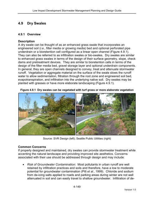
Figure <strong>4.9</strong>.1 <strong>Dry</strong> swales can be vegetated with turf grass or more elaborate vegetation<br />
Source: SVR Design (left); Seattle Public Utilities (right)<br />
Common Concerns<br />
If properly designed and maintained, dry swales can provide stormwater treatment while<br />
accenting the natural landscape and providing improved site aesthetics. Concerns<br />
associated with their use should be addressed through design and may include:<br />
• Risk of Groundwater Contamination: Most pollutants in urban runoff are well<br />
retained by infiltration practices and soils and therefore, have a low to moderate<br />
potential for groundwater contamination (Pitt et al., 1999). Chloride and sodium<br />
from de-icing salts applied to roads and parking areas during winter are not well<br />
attenuated in soil and can easily travel to shallow groundwater. Infiltration of de-<br />
4-149<br />
Version 1.0
Low Impact Development Stormwater Management Planning and Design Guide<br />
icing salt constituents is also known to increase the mobility of certain heavy<br />
metals in soil (e.g., lead, copper and cadmium), thereby raising the potential for<br />
elevated concentrations in underlying groundwater (Amrhein et al., 1992; Bauske<br />
and Goetz, 1993). However, very few studies that have sampled groundwater<br />
below infiltration facilities or roadside ditches receiving de-icing salt laden runoff<br />
have found concentrations of heavy metals that exceed drinking water standards<br />
(e.g., Howard and Beck, 1993; Granato et al., 1995). To minimize risk of<br />
groundwater contamination the following management approaches are<br />
recommended (Pitt et al., 1999; TRCA, 2009b):<br />
o stormwater infiltration practices should not receive runoff from high traffic<br />
areas where large amounts of de-icing salts are applied (e.g., busy<br />
highways), nor from pollution hot spots (e.g., source areas where land<br />
uses or activities have the potential to generate highly contaminated runoff<br />
such as vehicle fuelling, servicing or demolition areas, outdoor storage or<br />
handling areas for hazardous materials and some heavy industry sites);<br />
o prioritize infiltration of runoff from source areas that are comparatively less<br />
contaminated such as roofs, low traffic roads and parking areas; and,<br />
o apply sedimentation pretreatment practices (e.g., vegetated filter strip, pea<br />
gravel diaphragm, sedimentation forebay) before infiltration of road or<br />
parking area runoff.<br />
• Risk of Soil Contamination: Available evidence from monitoring studies indicates<br />
that small distributed stormwater infiltration practices do not contaminate<br />
underlying soils, even after more than 10 years of operation (TRCA, 2008).<br />
• On Private Property: If dry swales are installed on private lots, property owners or<br />
managers will need to be educated on their routine maintenance needs,<br />
understand the long-term maintenance plan, and be subject to a legally binding<br />
maintenance agreement. An incentive program such as a storm sewer user fee<br />
based on the area of impervious cover on a property that is directly connected to<br />
a storm sewer (i.e., does not first drain to a pervious area or LID practice) could<br />
be used to encourage property owners or managers to maintain existing<br />
practices. Alternatively, dry swales could be located in an expanded road rightof-way<br />
or “stormwater easement” so that municipal staff can access the facility in<br />
the event it fails to function properly.<br />
• Maintenance: The major maintenance requirement associated with dry swales is<br />
mowing or trimming vegetation. Occasionally, sediment will need to be removed,<br />
although this can be minimized by ensuring that upstream areas are stabilized<br />
and incorporating pretreatment devices (e.g., vegetated filter strips,<br />
sedimentation forebays, gravel diaphragms).<br />
• Erosion: Erosion can be prevented by limiting the allowable longitudinal slope<br />
and incorporating check dams. Additionally, designers can provide permanent<br />
reinforcement matting for swales with high velocity and temporary matting during<br />
the vegetation establishment period.<br />
4-150<br />
Version 1.0
Low Impact Development Stormwater Management Planning and Design Guide<br />
• Standing Water and Mosquitoes: Properly designed dry swales will not pond<br />
water at the surface for longer than 24 hours following a storm event. However,<br />
poor design, installation, or maintenance can lead to nuisance conditions.<br />
Physical Suitability and Constraints<br />
<strong>Dry</strong> swales can be implemented on a variety of development sites where development<br />
density, topography and depth to water table permit their application. Some key<br />
constraints for dry swales include:<br />
• Wellhead Protection: Facilities receiving road or parking lot runoff should not be<br />
located within two (2) year time-of-travel wellhead protection areas.<br />
• Available Space: <strong>Dry</strong> swale footprints are approximately 5 to 15% of their<br />
contributing drainage area. When applied to residential areas, the swale<br />
segments between driveways should be at least 5 metres in length.<br />
• Site Topography: <strong>Dry</strong> swales should be designed with longitudinal slopes<br />
generally ranging from 0.5 to 4%, and no greater than 6% (PDEP, 2006). On<br />
slopes steeper than 3%, check dams should be used.<br />
• Water Table: Designers should ensure that the bottom of the swale is separated<br />
from the seasonally high water table or top of bedrock elevation by at least one<br />
(1) metre to prevent groundwater contamination.<br />
• Soils: <strong>Dry</strong> swales can be located over any soil type, but hydrologic soil group A<br />
and B soils are best for achieving water balance benefits. Facilities should be<br />
located in portions of the site with the highest native soil infiltration rates. Where<br />
infiltration rates are less than 15 mm/hr (hydraulic conductivity less than 1x10 -6<br />
cm/s) an underdrain is required. Native soil infiltration rate at the proposed facility<br />
location and depth should be confirmed through measurement of hydraulic<br />
conductivity under field saturated conditions using the methods described in<br />
Appendix C.<br />
• Drainage Area and Runoff Volume to Site: <strong>Dry</strong> swales typically treat drainage<br />
areas of less than two hectares. If dry swales are used to treat larger areas, the<br />
velocity through the swale becomes too great to treat runoff or prevent erosion.<br />
Typical ratios of impervious drainage area to dry swale area range from 5:1 to<br />
15:1.<br />
<br />
Pollution Hot Spot Runoff: To protect groundwater from possible contamination,<br />
source areas where land uses or human activities have the potential to generate<br />
highly contaminated runoff (e.g., vehicle fueling, servicing and demolition areas,<br />
outdoor storage and handling areas for hazardous materials and some heavy<br />
industry sites) should not be treated dry swales designed for full or partial<br />
4-151<br />
Version 1.0
Low Impact Development Stormwater Management Planning and Design Guide<br />
infiltration. Facilities designed with an impermeable liner (filtration only facilities)<br />
can be used to treat runoff from pollution hot spots.<br />
• Setbacks from Buildings: <strong>Dry</strong> swales should be setback four (4) metres from<br />
building foundations. When located within 3 metres of building foundations, an<br />
impermeable liner and perforated pipe underdrain system should be used.<br />
• Proximity to Underground Utilities: Designers should consult local utility design<br />
guidance for the horizontal and vertical clearance between storm drains, ditches,<br />
and surface water bodies. It is feasible for on-site utilities to cross dry swales;<br />
however, this may require the use of special protection (e.g., double-casing) for<br />
the subject utility line.<br />
Typical Performance<br />
The ability of various dry swale design variations to help meet stormwater management<br />
objectives is summarized in Table <strong>4.9</strong>.1.<br />
BMP<br />
<strong>Dry</strong> swale with no<br />
underdrain or full<br />
infiltration<br />
<strong>Dry</strong> swale with<br />
underdrain or partial<br />
infiltration<br />
<strong>Dry</strong> swale with<br />
underdrain and<br />
impermeable liner or<br />
no infiltration<br />
Table <strong>4.9</strong>.1 Ability of dry swales to meet SWM objectives<br />
Water Balance<br />
Benefit<br />
Yes<br />
Partial – based on<br />
available storage<br />
volume beneath the<br />
underdrain and soil<br />
infiltration rate<br />
Partial – some volume<br />
reduction through<br />
evapotranspiration<br />
Water Quality<br />
Improvement<br />
Yes – size for water<br />
quality storage<br />
requirement<br />
Yes – size for water<br />
quality storage<br />
requirement<br />
Yes – size for water<br />
quality storage<br />
requirement<br />
Stream Channel<br />
Erosion Control<br />
Benefit<br />
Partial – based on<br />
available storage<br />
volume and infiltration<br />
rates<br />
Partial – based on<br />
available storage<br />
volume beneath the<br />
underdrain and soil<br />
infiltration rate<br />
Partial – some<br />
volume reduction<br />
through<br />
evapotranspiration<br />
Water Balance<br />
Limited data are available to define the typical runoff reduction rate for dry swales.<br />
Since they incorporate many of the same design elements, dry swales can be expected<br />
to perform similar to bioretention cells (Table <strong>4.9</strong>.2).<br />
Water Quality - Pollutant Removal Capacity<br />
While few field studies of the pollutant removal capacity of dry swales are available from<br />
cold climate regions like Ontario, it can be assumed that they would perform similar to<br />
bioretention facilities (see <strong>Section</strong> 4.5.1). Bioretention provides effective removal for<br />
many pollutants as a result of sedimentation, filtering, plant uptake, soil adsorption, and<br />
microbial processes. It is important to note that there is a relationship between the<br />
water balance and water quality functions. If a dry swale infiltrates and evaporates<br />
100% of the flow from a site, then there is essentially no pollution leaving the site in<br />
4-152<br />
Version 1.0
Low Impact Development Stormwater Management Planning and Design Guide<br />
surface runoff. Furthermore, treatment of infiltrated runoff will continue to occur as it<br />
moves through the native soils.<br />
Table <strong>4.9</strong>.2 Volumetric runoff reduction1 achieved by dry swales<br />
LID Practice Location Runoff Reduction 1 Reference<br />
<strong>Dry</strong> Swale<br />
without<br />
Washington 98% Horner et al. (2003)<br />
underdrain<br />
United Kingdom 94% Jefferies (2004)<br />
<strong>Dry</strong> Swale with<br />
underdrain<br />
Bioretention<br />
without<br />
underdrain<br />
Bioretention<br />
with underdrain<br />
Maryland 46 to 54% Stagge (2006)<br />
Connecticut 99% Dietz and Clausen (2006)<br />
Pennsylvania 80% Ermilio (2005)<br />
Pennsylvania 70% Emerson and Traver (2004)<br />
Ontario 58% TRCA (2008b)<br />
North Carolina 40 to 60% Smith and Hunt (2007)<br />
North Carolina 33 to 50% Hunt and Lord (2006)<br />
Maryland and North<br />
Carolina<br />
Runoff Reduction Estimate 2<br />
20 to 50% Li et al. (2009)<br />
85% without underdrain;<br />
45% with underdrain<br />
Notes:<br />
1. Runoff reduction estimates are based on differences in runoff volume between the practice and a<br />
conventional impervious surface over the period of monitoring.<br />
2. This estimate is provided only for the purpose of initial screening of LID practices suitable for achieving<br />
stormwater management objectives and targets. Performance of individual facilities will vary depending on<br />
site specific contexts and facility design parameters and should be estimated as part of the design process<br />
and submitted with other documentation for review by the approval authority.<br />
Performance results from both laboratory and field studies indicate that bioretention<br />
systems have the potential to be one of the most effective BMPs for pollutant removal<br />
(TRCA, 2009b). Excellent pollutant removal rates have been observed through field<br />
studies for total suspended solids (Roseen et al., 2009), polycyclic aromatic<br />
hydrocarbons (TRCA, 2008b; Diblasi et al., 2009), and metals (Davis et al., 2003; Hunt<br />
et al., 2006; Roseen et al., 2006; Davis, 2007; TRCA, 2008b). Good removal rates for<br />
metals have even been observed in bioretention facilities receiving snow melt that<br />
contains de-icing salt constituents (Muthanna et al., 2007).<br />
Field investigations of nutrient removal by bioretention facilities have produced more<br />
variable results (TRCA, 2009b). Some facilities have been observed to increase total<br />
phosphorus in infiltrated water (Dietz and Clausen, 2005; Hunt et al., 2006; TRCA,<br />
2008b). These findings have been attributed to leaching from the filter media soil<br />
mixture which contained high phosphorus content. To avoid phosphorus export, the<br />
phosphorus content (i.e., Phosphorus Index) of the filter media soil mixture should be<br />
examined and kept between 10 to 30 ppm (Hunt and Lord, 2006). While moderate<br />
4-153<br />
Version 1.0
Low Impact Development Stormwater Management Planning and Design Guide<br />
reductions in total nitrogen and ammonia nitrogen have been observed in laboratory<br />
studies (Davis et al., 2001) and field studies (Dietz and Clausen, 2005), nitrate nitrogen<br />
has consistently observed to be low.<br />
Little data exists on the ability of bioretention to reduce bacteria concentrations, but<br />
preliminary results report good removal rates for fecal coliform bacteria (Rusciano and<br />
Obropta, 2005; Hunt et al., 2008; TRCA, 2008b).<br />
Several factors that can greatly increase or decrease the pollutant removal capacity of<br />
dry swales are provided in Table <strong>4.9</strong>.4.<br />
Table <strong>4.9</strong>.3 Factors that influence the pollutant removal capacity of dry swales<br />
Factors that Reduce Removal Rates<br />
Factors that Enhance Removal Rates<br />
Longitudinal slope > 3% Longitudinal slope between 0.5 to 3%<br />
Measured soil infiltration rate is less than 15<br />
mm/hr<br />
Measured soil infiltration rate is 15 mm/hr or<br />
greater<br />
Filter media P-Index values > 30 ppm 1 Filter media P-Index values < 30 ppm 1<br />
Flow velocity within swale > 0.5 m/s during a 4<br />
hour, 25 mm Chicago storm event<br />
No pretreatment<br />
Swale side slopes steeper than 3:1 (H:V)<br />
Flow velocity within swale is 0.5 m/s or less<br />
during a 4 hour, 25 mm Chicago storm event<br />
Pretreatment with vegetated filter strips, gravel<br />
diaphragms and/or sedimentation forebays<br />
Swale side slopes 3:1 (H:V) or less<br />
Notes:<br />
1. P-index values refers to phosphorus soil test index values in parts per million (ppm). See www.omafra.gov.on.ca<br />
for information on soil testing and a list of accredited soil laboratories.<br />
Stream Channel Erosion Control<br />
While most dry swales are not designed to provide channel erosion control storage<br />
volume, the high degree of runoff reduction reported in performance monitoring studies<br />
suggests that they have the potential to protect downstream channels from erosion. If<br />
space is available, they may be designed for extended detention.<br />
<strong>4.9</strong>.2 Design Template<br />
Applications<br />
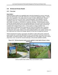
The linear nature of dry swales makes them well-suited to treat road runoff as they can<br />
be incorporated into road rights-of-way (see Figure <strong>4.9</strong>.2). They are also a suitable<br />
practice for managing runoff from parking lots, roofs and pervious surfaces, such as<br />
yards, parks and landscaped areas. <strong>Dry</strong> swales can be used for storing and treating<br />
snow from the contributing drainage area.<br />
<strong>Dry</strong> swales require a considerable amount of space, often making them impractical in<br />
densely developed urban areas. Where development density, topography and depth to<br />
water table permit, dry swales can be used to provide stormwater conveyance in place<br />
of conventional curb and gutter and storm drain systems.<br />
4-154<br />
Version 1.0
Low Impact Development Stormwater Management Planning and Design Guide<br />
<strong>Dry</strong> swales vary in appearance based on the type of vegetation. <strong>Swales</strong> can be planted<br />
with turf grass, tall meadow grasses, decorative herbaceous cover, or trees (Figure<br />
<strong>4.9</strong>.2).<br />
Figure <strong>4.9</strong>.2 <strong>Dry</strong> swales are well suited to road rights-of-way and parking lots<br />
Source: City of Portland (left); Lake County Illinois (centre); Portland Public Schools (right)<br />
Design Guidance<br />
Geometry and Site Layout<br />
Design guidance regarding the geometry and layout of dry swales is provided below:<br />
• Shape: A parabolic shape is preferable for aesthetic, maintenance and hydraulic<br />
reasons. However, design may be simplified with a trapezoidal cross section as<br />
long as the engineered soil (filter media) bed boundaries lay in the flat bottom<br />
areas. Swale length between culverts should be 5 metres or greater.<br />
• Bottom Width: For the trapezoidal cross section, the bottom width should be<br />
between 0.75 and 3 metres. When greater widths are desired, bioretention cell<br />
designs (<strong>Section</strong> 4.5) should be used.<br />
• Side Slopes: The side slopes of the channel should be no steeper than 3:1 for<br />
maintenance considerations (mowing). Flatter slopes are encouraged where<br />
adequate space is available to aid in providing pretreatment for sheet flows<br />
entering the swale.<br />
• Longitudinal Slope: The slope of the swale should be as gradual as possible to<br />
permit the temporary ponding of the water quality storage requirement. <strong>Dry</strong><br />
swales should be designed with longitudinal slopes generally ranging from 0.5 to<br />
4%. On slopes steeper than 3%, check dams should be used. Check dam<br />
spacing should be based on the slope and desired ponding volume. They should<br />
4-155<br />
Version 1.0
Low Impact Development Stormwater Management Planning and Design Guide<br />
be spaced far enough apart to allow access for maintenance equipment (e.g.,<br />
mowers).<br />
Typical Details<br />
Figure <strong>4.9</strong>.3 Schematic of a dry swale<br />
Also see Figure 4.10 from the OMOE Stormwater Management Planning and Design<br />
Manual (OMOE, 2003).<br />
Pretreatment<br />
Pretreatment devices capture and remove coarse sediment particles before they reach<br />
the engineered soil (i.e., filter media) bed to prevent premature clogging and prolong<br />
effective function of dry swales. A two-cell design that incorporates a sedimentation<br />
4-156<br />
Version 1.0
Low Impact Development Stormwater Management Planning and Design Guide<br />
forebay is recommended as it provides the most-effective pretreatment. Several<br />
pretreatment measures are feasible, depending on the method of conveyance and the<br />
drainage area:<br />
• Sedimentation forebay (two-cell design): Forebay ponding volume should<br />
account for 25% of the water quality storage requirement and be designed with a<br />
2:1 length to width ratio. This pre-treatment device is the most effective and has<br />
the easiest sediment-removal mechanism.<br />
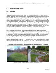
• Grass filter strip (sheet flow): These grass strips should ideally be a minimum of<br />
three metres in width. However, space constraints at some sites prohibit this<br />
width. If smaller strips are used, more frequent maintenance of the filter bed can<br />
be anticipated.<br />
• Gravel diaphragm (sheet flow): A gravel diaphragm at the end of pavement<br />
should run perpendicular to the flow path to promote settling. The pea gravel<br />
diaphragm (a small trench running along the top of the dry swale) serves two<br />
purposes. First, it acts as a pretreatment device, settling out sediment particles<br />
before they reach the practice. Second, it acts as a level spreader, maintaining<br />
sheet flow into the dry swale. If the contributing drainage area is steep, then<br />
larger stone should be used in the diaphragm. A 50 to 150 mm drop from a hardedged<br />
surface into a gravel or stone diaphragm can be used to dissipate energy<br />
and promote settling.<br />
• Rip rap and/or dense vegetation (channel flow): These energy dissipation<br />
techniques are acceptable as pre-treatment on small swales with a drainage area<br />
of less than 100 square metres.<br />
Conveyance and Overflow<br />
<strong>Dry</strong> swales should be designed for a maximum velocity of 0.5 m/s or less for a 4 hour<br />
25 mm Chicago storm event. The swale should also convey the locally required design<br />
storm (usually the 10 year storm) at non-erosive velocities with freeboard provided<br />
above the required design storm water level.<br />
Monitoring Wells<br />
A capped vertical standpipe consisting of an anchored 100 to 150 millimetre diameter<br />
perforated pipe with a lockable cap installed to the bottom of the facility at the furthest<br />
downgradient end is recommended for monitoring the length of time required to fully<br />
drain the facility between storms.<br />
Gravel Storage Layer<br />
• Depth: Should be a minimum of 300 mm deep and sized to provide the required<br />
storage volume. Granular material should be 50 mm diameter clear stone.<br />
4-157<br />
Version 1.0
Low Impact Development Stormwater Management Planning and Design Guide<br />
• Pea gravel choking layer: A 100 mm deep layer of pea gravel (3 to 10 mm<br />
diameter clear stone) should be placed on top of the coarse gravel storage layer<br />
as a choking layer separating it from the overlying filter media bed.<br />
Filter Media<br />
• Composition: The recommended bioretention filter media soil mixture is:<br />
Component Percent by Weight<br />
Sand (2.0 to 0.050 mm dia.) 85 to 88 %<br />
Fines (< 0.050 mm dia.) 8 to 12 %<br />
Organic matter 3 to 5 %<br />
To ensure a consistent and homogeneous bed, filter media should come premixed<br />
from an approved vendor. The filter media soil mixture should have the<br />
following properties:<br />
o The recommended Phosphorus soil test (P- index) value is between 10 to<br />
30 ppm (Hunt and Lord, 2006). Visit the Ontario Ministry of Agriculture,<br />
Food, and Rural Affairs website (www.omafra.gov.on.ca) for information<br />
on soil testing and a list of accredited soil laboratories.<br />
o Soils with cationic exchange capacity (CEC) exceeding 10 milliequivalents<br />
per 100 grams (meq/100 g) are preferred for pollutant removal (Hunt and<br />
Lord, 2006).<br />
o The mixture should be free of stones, stumps, roots, or other similar<br />
objects larger than 50 mm.<br />
o For optimal plant growth, the recommended pH is between 5.5 to 7.5.<br />
Lime can be used to raise the pH, or iron sulphate plus sulphur can be<br />
used to lower the pH. The lime and iron sulphate need to be uniformly<br />
mixed into the soil (Low Impact Development Center, 2003a).<br />
o The media should have an infiltration rate of greater than 25 mm/hr.<br />
One adaptation is to design the media as a sand filter with organic content only<br />
at the top. Leaf compost tilled into the top layers will provide organic content for<br />
the plants. If grass is the only vegetation, the ratio of compost may be reduced<br />
(Hirschman, 2008; Smith and Hunt, 2007).<br />
• Depth: The recommended filter bed depth is between 1.0 and 1.25 metres.<br />
However, in constrained applications, pollutant removal benefits may be<br />
achieved in filter beds as shallow as 500 millimetres. (Davis et al., 2009; and<br />
Hunt et al., 2006). If trees are included in the bioretention design, then the filter<br />
bed depth must be at least 1.0 metre and have soil volume to accommodate the<br />
root structure of mature trees. A minimum of 12 cubic metres of shared root<br />
space is recommended for healthy canopy trees. Use perennials, shrubs or<br />
grasses instead of trees when landscaping shallower filter beds.<br />
4-158<br />
Version 1.0
Low Impact Development Stormwater Management Planning and Design Guide<br />
• Mulch: A 75 millimetre layer of mulch on the surface of the filter bed enhances<br />
plant survival, suppresses weed growth, and pre-treats runoff before it reaches<br />
the filter bed. Shredded hardwood bark mulch makes a very good surface cover,<br />
as it retains a significant amount of nitrogen and typically will not float away. The<br />
mulch layer also plays a key role in the removal of heavy metals, sediment, and<br />
nutrients (Davis et al., 2001; Davis et al., 2003; Davis et al., 2006; Dietz and<br />
Clausen, 2006; Hunt, 2003; and Hsieh and Davis, 2005). Alternately, temporary<br />
or permanent erosion control matting can be used in lieu of the mulch layer. The<br />
matting should be coconut fiber or another durable material, and should be<br />
installed prior to the landscaping. Matting is recommended where flow velocities<br />
would likely wash the mulch away.<br />
Underdrain<br />
• Only needed where native soil infiltration rate is less than 15 mm/hr (hydraulic<br />
conductivity of less than 1x10 -6 cm/s).<br />
• Should consist of a perforated pipe embedded in the coarse gravel storage layer<br />
at least 100 mm above the bottom of the gravel storage layer.<br />
• HDPE or equivalent material perforated pipes with smooth interior walls should<br />
be used. Pipes should be over-sized to accommodate freezing conditions. A<br />
minimum 200 mm diameter underdrain is recommended for this reason (MPCA,<br />
2005). Underdrains should be capped on the upstream end(s).<br />
• A strip of geotextile filter fabric placed between the filter media and pea gravel<br />
choking layer over the perforated pipe is optional to help prevent fine soil<br />
particles from entering the underdrain. Table 4.5.7 provides further detail<br />
regarding geotextile specifications.<br />
• A vertical standpipe connected to the underdrain can be used as a cleanout and<br />
monitoring well.<br />
Landscaping<br />
Designers should choose grasses, herbaceous plants, or trees that can withstand both<br />
wet and dry periods as well as relatively high velocity flows within the swale. Where<br />
possible a combination of native trees, shrubs and perennial herbs should be used in<br />
addition to grasses. For applications along roads and parking lots, where snow may be<br />
plowed or stored, non-woody and salt tolerant species should be chosen. A list of<br />
native plant species suitable for dry swale applications and direction on picking the right<br />
plants is provided in Appendix B.<br />
Other Details<br />
Check dams or weirs may be used to obtain the necessary water quality storage<br />
volume. The check dams should be spaced based on the longitudinal slope and<br />
ponding requirements, while considering the maximum ponding depth. Check dams<br />
should be composed of wood or stone. Alternatively, driveway culverts can be used for<br />
this purpose.<br />
In urban settings, trash accumulation and pedestrian traffic call for special<br />
consideration. Consider the following adaptations:<br />
4-159<br />
Version 1.0
Low Impact Development Stormwater Management Planning and Design Guide<br />
• To protect vegetation and prevent soil compaction, fencing (low, wrought iron<br />
fences), low walls, bollards and chains, curbs, and constructed walkways can be<br />
incorporated.<br />
• Trash racks can be installed between pretreatment devices and the swale or<br />
across curb cuts.<br />
Other Design Resources<br />
Several other manuals that provide useful design guidance for dry swales are:<br />
Center for Watershed Protection (CWP). 2007b. Urban Stormwater Retrofit<br />
Practices: Manual 3 in the Urban Subwatershed Restoration Manual Series.<br />
Ellicott City, MD.<br />
Claytor, R. and T. Schueler. 1996. Design of Stormwater Filtering Systems.<br />
Center for Watershed Protection. Ellicott City, MD.<br />
Ontario Ministry of the Environment (OMOE). 2003. Stormwater Management<br />
Planning and Design Manual. Ontario, Canada.<br />
BMP Sizing<br />
The surface channel component of dry swales should be designed for a maximum flow<br />
velocity of 0.5 m/sec. during the 25 mm, 4 hour Chicago storm event over the drainage<br />
area.<br />
The sizing methodology for the filter media bed component of dry swales is the same as<br />
that for bioretention practices. The depth of a dry swale filter media bed designed for<br />
full infiltration (i.e., no underdrain) is dependent on the native soil infiltration rate,<br />
porosity (void space ratio) of the filter bed and gravel storage layer media (i.e,<br />
aggregate material used in the stone reservoir) and the targeted time period to achieve<br />
complete drainage between storm events. Assuming a void space ratio of 0.4 for both<br />
the filter bed and gravel storage layer media, the maximum allowable depth of the filter<br />
bed can be calculated using the following equation:<br />
d b max = i * (t s –d p / i) / V r<br />
Where:<br />
d b max = Maximum filter media bed depth (mm)<br />
i = Infiltration rate for native soils (mm/hr)<br />
V r = Void space ratio for filter bed and gravel layer (assume 0.4)<br />
t s = Time to drain (design for 48 hour time to drain is recommended)<br />
= Maximum surface ponding depth (mm)<br />
d p<br />
For designs that include an underdrain, the filter media bed should be 1 to 1.25 metres<br />
in depth. The following equation can be used to determine the maximum depth of the<br />
stone reservoir below the invert of the underdrain pipe:<br />
4-160<br />
Version 1.0
Low Impact Development Stormwater Management Planning and Design Guide<br />
d r max = i * t s / V r<br />
Where:<br />
d r max = Maximum depth of stone reservoir below the underdrain pipe<br />
The value for native soil infiltration rate (i) used in the above equations should be the<br />
design infiltration rate that incorporates a safety correction factor based on the ratio of<br />
the mean value at the proposed bottom elevation of the practice to the mean value in<br />
the least permeable soil horizon within 1.5 metres of the proposed bottom elevation<br />
(see Appendix C, Table C2). For designs with no underdrain that are located on less<br />
permeable soils, a minimum filter bed depth of 0.5 metres is recommended to ensure<br />
water quality benefits will be achieved. For designs with filter bed depths less than 1<br />
metre, a maximum surface ponding depth of 85 to 100 mm is recommended.<br />
Once the depth of the filter media bed is determined the water quality volume,<br />
computed using the methods in the relevant CVC and TRCA stormwater management<br />
criteria documents (CVC, 2010; TRCA, 2010), can be used to determine the footprint<br />
needed using the following equation:<br />
A f = WQV / (d b * V r )<br />
Where:<br />
A f = Footprint surface area (m 2 )<br />
WQV = Water quality volume (m 3 )<br />
d b = Filter media bed depth (m)<br />
V r = Void space ratio for filter bed and gravel layer (assume 0.4)<br />
The ratio of impervious drainage area to footprint surface area of the practice should be<br />
between 5:1 and 15:1 to limit the rate of accumulation of fine sediments and thereby<br />
prevent clogging.<br />
Design Specifications<br />
Recommended design specifications for dry swales are provided in Table <strong>4.9</strong>.4.<br />
Table <strong>4.9</strong>.4 Design specifications for dry swales<br />
Component Specification Quantity<br />
Filter Media<br />
Composition<br />
Filter Soil Mixtures to contain:<br />
85 to 88% sand<br />
8 to 12% soil fines<br />
3 to 5% organic matter in form of leaf<br />
compost<br />
Other Criteria:<br />
Phosphorus soil test (P-Index) value 10 to 30<br />
ppm<br />
Cationic exchange capacity (CEC) greater<br />
than 10 meq/100 g<br />
pH between 5.5 to 7.5<br />
Recommended depth is<br />
between 1.0 and 1.25 metres.<br />
Alternative depths may be<br />
appropriate in constrained<br />
applications.<br />
Volumetric computation based<br />
on surface area and depth used<br />
in design computations.<br />
4-161<br />
Version 1.0
Low Impact Development Stormwater Management Planning and Design Guide<br />
Component Specification Quantity<br />
Geotextile<br />
Material specifications should conform to<br />
Ontario Provincial Standard Specification<br />
(OPSS) 1860 for Class II geotextile fabrics.<br />
Should be woven monofilament or non-woven<br />
needle punched fabrics. Woven slit film and<br />
non-woven heat bonded fabrics should not be<br />
used as they are prone to clogging.<br />
Primary considerations are:<br />
- Suitable apparent opening size (AOS) for nonwoven<br />
fabrics, or percent open area (POA) for<br />
woven fabrics, to maintain water flow even with<br />
sediment and microbial film build-up;<br />
- Texture (i.e., grain size distribution) of the<br />
overlying native soil, filter media soil or<br />
aggregate material; and<br />
- Permeability of the native soil.<br />
The following geotextile fabric selection criteria<br />
are suggested (adapted from AASHTO, 2002;<br />
Smith, 2006; and U.S. Dept. of Defense, 2004):<br />
Apparent Opening Size (AOS; max. average<br />
roll value) or Percent Open Area (POA)<br />
For fine grained soils with more than 85% of<br />
particles smaller than 0.075 mm (passing a No.<br />
200 sieve):<br />
AOS ≤ 0.3 mm (non-woven fabrics)<br />
For fine grained soils with 50 to 85% of particles<br />
smaller than 0.075 mm (passing a No. 200<br />
sieve):<br />
AOS ≤ 0.3 mm (non-woven fabrics)<br />
POA ≥ 4% (woven fabrics)<br />
For coarser grained soils with 5 to 50% of<br />
particles smaller than 0.075 mm (passing a No.<br />
200 sieve):<br />
AOS ≤ 0.6 mm (non-woven fabrics)<br />
POA ≥ 4% (woven fabrics)<br />
For coarse grained soils with less than 5% of<br />
particles smaller than 0.075 mm (passing a No.<br />
200 sieve):<br />
AOS ≤ 0.6 mm (non-woven fabrics)<br />
POA ≥ 10% (woven fabrics)<br />
Hydraulic Conductivity (k, in cm/sec)<br />
k (fabric) > k (soil)<br />
Permittivity (in sec -1 )<br />
Where,<br />
Between the filter media bed<br />
and gravel storage layer (stone<br />
reservoir).<br />
4-162<br />
Version 1.0
Low Impact Development Stormwater Management Planning and Design Guide<br />
Component Specification Quantity<br />
Permittivity = k (fabric)/thickness (fabric):<br />
For fine grained soils with more than 50% of<br />
particles smaller than 0.075 mm (passing a No.<br />
200 sieve), Permittivity should be 0.1 sec -1<br />
For coarser grained soils with 15 to 50% of<br />
particles smaller than 0.075 mm (passing a No.<br />
200 sieve), Permittivity should be 0.2 sec -1 .<br />
Gravel<br />
For coarse grained soil with less than 15% of<br />
particles smaller than 0.075 mm (passing a No.<br />
200 sieve), Permittivity should be 0.5 sec -1 .<br />
Washed 50 mm diameter clear stone should be<br />
used to surround the underdrain and for the<br />
gravel storage layer<br />
Volume based on dimensions,<br />
assuming a void space ratio of<br />
0.4.<br />
Washed 3 to 10 mm diameter clear stone<br />
should be used for pea gravel choking layer.<br />
Underdrain Perforated HDPE or equivalent, minimum 100<br />
mm diameter, 200 mm recommended.<br />
Check Dams Check dams should be constructed of a<br />
non-erosive material such as wood,<br />
gabions, riprap, or concrete. All check dams<br />
should be underlain with filter fabric<br />
conforming to local design standards.<br />
Wood used for check dams should consist<br />
of pressure treated logs or timbers, or<br />
water-resistant tree species such as cedar,<br />
hemlock, swamp oak or locust.<br />
Mulch or Matting Mulch should be shredded hardwood bark<br />
at least 75 mm deep.<br />
Where flow velocities dictate, use erosion<br />
and sediment control matting – coconut<br />
fiber or equivalent.<br />
Perforated pipe for length of<br />
swale where required.<br />
Non-perforated pipe as<br />
needed to connect with storm<br />
drain system.<br />
One or more caps.<br />
T’s for underdrain<br />
configuration.<br />
Computation of check dam<br />
material needed based on<br />
surface area and depth used in<br />
design computations.<br />
<br />
<br />
A 75 mm layer on the<br />
surface of the filter bed.<br />
Matting – based on surface<br />
area of filter bed.<br />
Construction Considerations<br />
Sequencing<br />
Ideally, dry swale sites should remain outside the limit of disturbance until construction<br />
of the swale begins to prevent soil compaction by heavy equipment. <strong>Dry</strong> swale locations<br />
should never be used as the site of sediment basins during construction, as the<br />
concentration of fines will prevent post-construction infiltration. To prevent sediment<br />
from clogging the surface of a dry swale, stormwater should be diverted away from the<br />
practice until the drainage area is fully stabilized.<br />
4-163<br />
Version 1.0
Low Impact Development Stormwater Management Planning and Design Guide<br />
The construction sequence for dry swales is similar to that used for bioretention (for<br />
further details see section 4.5). Three key steps should be emphasized. First, the<br />
contributing drainage area has been fully stabilized prior to dry swale construction.<br />
Second, designers should check elevations at driveway culverts and check dams to<br />
ensure ponding depths are achieved. Lastly, the swale channel and side slopes should<br />
be rapidly stabilized using biodegradable geotextile blankets and seeding before<br />
bringing the swale “on line”.<br />
Construction Inspection<br />
Common construction pitfalls can be avoided by careful construction supervision that<br />
focuses on the following aspects:<br />
Erosion and Sediment Control<br />
• <strong>Dry</strong> swale locations should be blocked from construction traffic and should not be<br />
used for erosion and sediment control.<br />
• Proper erosion and sediment controls should be in place for the drainage area<br />
during construction, including sediment fencing around the swale.<br />
Materials<br />
• Gravel for the underdrain should be clean and washed; no fines should be<br />
present in the material.<br />
• Underdrain pipe material should be perforated and of the correct size.<br />
• A cap should be placed on the upstream (but not the downstream) end of the<br />
underdrain.<br />
• Filter media should be tested to confirm that it meets specifications.<br />
• Mulch composition should be correct.<br />
• Matting, if used, should be correct specification, and durable enough to last at<br />
least 2 growing seasons.<br />
Elevations<br />
Elevations of the following items should be checked for accuracy:<br />
• Depth of the gravel and invert of the underdrain<br />
• Inverts for inflow and outflow points<br />
• Filter depth after media is placed<br />
• Ponding depth provided between the surface of the filter bed and the overflow<br />
structure<br />
• Mulch depth<br />
Landscaping and Stabilization<br />
• Correct vegetation should be planted.<br />
• Pretreatment area should be stabilized.<br />
• Drainage area should be stabilized prior to directing water to the swale.<br />
The following items should be checked after the first rainfall event, and adjustments<br />
should be made as necessary:<br />
4-164<br />
Version 1.0
Low Impact Development Stormwater Management Planning and Design Guide<br />
• Sheet flow should occur as designed.<br />
• Outfall protection/energy dissipation at concentrated inflow should be stable.<br />
• Ponded water on the surface of the swale should drain within 24 hours of the end<br />
of the storm event. The filter media bed should fully drain within 72 hours.<br />
• Sediment accumulation should not be present.<br />
<strong>4.9</strong>.3 Maintenance and Construction Costs<br />
Inspection and Maintenance<br />
Maintenance of dry swales mostly involves maintenance of the vegetative cover as well<br />
as periodic inspection for less frequent maintenance needs. Generally, routine<br />
maintenance will be the same for any other landscaped area; weeding, pruning, mowing<br />
and litter removal. Inspections annually and after every major storm event (> 25 mm),<br />
will determine whether corrective action is necessary to address gradual deterioration or<br />
abnormal conditions.<br />
For the first six months following construction, the site should be inspected after each<br />
storm event greater than 10 mm, or a minimum of twice. Subsequently, inspections<br />
should be conducted in the spring of each year and after rainfall events greater than 25<br />
mm. Two or three growing seasons may be required to establish vegetation to the<br />
desired level. During this period, erosion and sediment control practices, such as mats<br />
or blankets, should be used to help protect swale structure.<br />
The expected lifespan of infiltration practices is not well understood, however, it can be<br />
expected that it will vary depending on pretreatment practice maintenance frequency,<br />
and the sediment texture and load coming from the catchment.<br />
Routine Inspection and Maintenance<br />
Routine inspection and maintenance activities, as shown in Table <strong>4.9</strong>.5, are necessary<br />
for the continued operation of dry swales. Suggested inspection items and corrective<br />
actions are provided in Table <strong>4.9</strong>.6.<br />
4-165<br />
Version 1.0
Low Impact Development Stormwater Management Planning and Design Guide<br />
<br />
<br />
<br />
<br />
<br />
<br />
<br />
<br />
<br />
<br />
Table <strong>4.9</strong>.5 Suggested routine inspection and maintenance activities for dry swales<br />
Activity<br />
Inspect for vegetation density (at least 80% coverage),<br />
damage by foot or vehicular traffic, channelization,<br />
accumulation of debris, trash and sediment, and structural<br />
damage to pretreatment devices.<br />
Regular watering may be required during the first two years<br />
while vegetation is becoming established;<br />
Mow grass to maintain height between 75 to 150 mm;<br />
Remove trash and debris from pretreatment devices, the<br />
swale surface and inlet and outlets.<br />
Remove accumulated sediment from pretreatment devices,<br />
inlets and outlets;<br />
Trim trees and shrubs;<br />
Replace dead vegetation, remove invasive growth, dethatch,<br />
remove thatching and aerate (PDEP, 2006;<br />
Repair eroded or sparsely vegetated areas;<br />
Remove accumulated sediment on the swale surface when<br />
dry and exceeds 25 mm depth (PDEP, 2006);<br />
If gullies are observed along the swale, regrading and<br />
revegetating may be required.<br />
Schedule<br />
After every major storm event<br />
(>25 mm), quarterly for the first<br />
two years, and twice annually<br />
thereafter.<br />
As needed for the first two years<br />
of operation.<br />
At least twice annually. More<br />
frequently if desired for aesthetic<br />
reasons.<br />
Annually or as needed<br />
Table <strong>4.9</strong>.6 Suggested inspection items and corrective actions for dry swales<br />
Inspection Item<br />
Vegetation health,<br />
diversity and<br />
density<br />
Sediment build up<br />
and clogging at<br />
inlets<br />
Ponding for more<br />
than 48 hours<br />
Corrective Actions<br />
• Remove dead and diseased plants.<br />
• Add reinforcement planting to maintain desired vegetation density.<br />
• Prune woody matter.<br />
• Check soil pH for specific vegetation.<br />
• Add mulch to maintain 75 mm layer.<br />
• Remove sand that may accumulate at the inlets or on the filter bed<br />
surface following snow melt.<br />
• Examine drainage area for bare soil and stabilize. Apply erosion control<br />
such as silt fence until the area is stabilized.<br />
• Check that pretreatment is properly functioning. For example, inspect<br />
filter strips for erosion or gullies. Reseed as necessary.<br />
• Check underdrain for clogging and flush out.<br />
• Apply core aeration or deep tilling<br />
• Mix amendments into the soil<br />
• Remove the top 75 mm of filter media soil<br />
• Replace filter media soil<br />
Installation and Operation Costs<br />
Very limited information is available regarding dry swale construction costs. Due to<br />
similarities in design, dry swale construction costs are likely comparable to those for<br />
bioretention. In a study by the Center for Watershed Protection to estimate and<br />
compare construction costs for various stormwater BMPs, the median base construction<br />
cost for bioretention was estimated to be $62,765 (2006 USD) per impervious hectare<br />
treated with estimates ranging from $49,175 to $103,165 (CWP, 2007b). These<br />
estimates do not include design and engineering costs, which could range from 5 to<br />
4-166<br />
Version 1.0
Low Impact Development Stormwater Management Planning and Design Guide<br />
40% of the base construction cost (CWP, 2007b). However, since dry swales serve as<br />
a conveyance measure, their cost is offset by the savings in curb and gutter, inlets, and<br />
storm sewer pipe as well as the reduction in other stormwater best management<br />
practices needed downstream.<br />
<strong>4.9</strong>.4 References<br />
American Association of State Highway and Transportation Officials (AASHTO). 2002.<br />
Geotextile Specification for Highway Applications. AASHTO M 288-00. Washington DC.<br />
Amrhein, C., Strong, J.E., and Mosher, P.A. 1992. Effect of de-icing salts on metal and<br />
organic matter mobilization in roadside soils. Environmental Science and Technology.<br />
Vol. 26, No. 4, pp. 703-709.<br />
Bauske, B., Goetz, D. 1993. Effects of de-icing salts on heavy metal mobility. Acta<br />
Hydrochimica Hydrobiologica. Vol. 21. pp. 38-42.<br />
Center for Watershed Protection (CWP). 2007a. National Pollutant Removal Database –<br />
Version 3. September 2007. Ellicott City, MD.<br />
Center for Watershed Protection (CWP). 2007b. Urban Stormwater Retrofit Practices:<br />
Manual 3 in the Urban Subwatershed Restoration Manual Series. Ellicott City, MD.<br />
City of Portland. 2004. Portland Stormwater Management Manual. Prepared by the<br />
Bureau of Environmental Services (BES). Portland, OR.<br />
Claytor, R. and T. Schueler. 1996. Design of Stormwater Filtering Systems. Center for<br />
Watershed Protection. Ellicott City, MD.<br />
Davis, A.P. 2007. Field performance of bioretention: Water Quality. Environmental<br />
Engineering Science. Vol. 24. No. 8. pp. 1048-1064.<br />
Davis, A. 2008. Field performance of bioretention: hydrology impacts. Journal of<br />
Hydrological Engineering. Feb 2008. 90-96.<br />
Davis, A., M. Shokouhian, H. Sharma and C. Minami. 2001. Laboratory Study of<br />
Biological Retention for Urban Stormwater Management. Water Environment Research.<br />
73(5): 5-14.<br />
Davis, A., M. Shokouhian, H. Sharma and C. Minami. 2006. Water Quality Improvement<br />
through Bioretention Media: Nitrogen and Phosphorus Removal. Water Environment<br />
Research. 78(3): 284-293.<br />
4-167<br />
Version 1.0
Low Impact Development Stormwater Management Planning and Design Guide<br />
Davis, A., M. Shokouhian, H. Sharma, C. Minami and D. Winogradoff. 2003. Water<br />
Quality Improvement Through Bioretention: Lead, Copper, and Zinc Removal. Water<br />
Environment Research. 75(1): 73-82.<br />
Davis, A., W. Hunt, R. Traver, and M. Clar. 2009. Bioretention Technology: Overview of<br />
Current Practice and Future Needs. Journal of Environmental Engineering. 135(3): 109-<br />
117<br />
Diblasi, C.J., Li, H., Davis, A.P. and Ghosh, U. 2009. Removal and Fate of Polycyclic<br />
Aromatic Hydrocarbon Pollutants in an Urban Stormwater Bioretention Facility.<br />
Environmental Science and Technology. Vol. 43. No. 2. Pp. 494-499.<br />
Dietz, M.E. and J.C. Clausen. 2006. Saturation to Improve Pollutant Retention in a Rain<br />
Garden. Environmental Science &Technology. 40(4): 1335-1340.<br />
Ermilio, J. 2005. Characterization study of a bio-infiltration stormwater BMP. M.S.<br />
Thesis. Villanova University. Department of Civil and Environmental Engineering.<br />
Philadelphia, PA.<br />
Emerson, C., Traver, R. 2004. The Villanova Bio-infiltration Traffic Island: Project<br />
Overview. Proceedings of 2004 World Water and Environmental Resources Congress<br />
(EWRI/ASCE). Salt Lake City, Utah, June 22 – July 1, 2004.<br />
Granato, G.E., Church, P.E., Stone, V.J. 1995. Mobilization of Major and Trace<br />
Constituents of Highway Runoff in Groundwater Potentially Caused by De-icing<br />
Chemical Migration. Transportation Research Record. No. 1483.<br />
Horner, R., H. Lim and S. Burges. 2003. Hydrologic monitoring of the Seattle ultra-urban<br />
stormwater management project. University of Washington. Department of Civil and<br />
Environmental Engineering. Water Resources Series. Technical Report 170.<br />
Howard, K.W.F. and Beck, P.J. 1993. Hydrogeochemical implications of groundwater<br />
contamination by road de-icing chemicals. Journal of Contaminant Hydrology. Vol. 12.<br />
pp. 245-268.<br />
Hsieh, C.H. and A.P. Davis. 2005. Multiple-Event Study of Bioretention for Treatment of<br />
Urban Storm Water Runoff. Water Science and Technology. 51(3-4): 177-181.<br />
Hunt, W.F. and W.G. Lord. 2006. Bioretention Performance, Design, Construction, and<br />
Maintenance. North Carolina Cooperative Extension Service Bulletin. Urban Waterways<br />
Series. AG-588-5. North Carolina State University. Raleigh, NC.<br />
Hunt, W.F., A.R. Jarrett, J.T. Smith, and L.J. Sharkey. 2006. Evaluating Bioretention<br />
Hydrology and Nutrient Removal at Three Field Sites in North Carolina. ASCE Journal<br />
of Irrigation and Drainage Engineering. 132(6): 600-608.<br />
4-168<br />
Version 1.0
Low Impact Development Stormwater Management Planning and Design Guide<br />
Jefferies, C. 2004. <strong>Sustainable</strong> drainage systems in Scotland: the monitoring<br />
programme. Scottish Universities SUDS Monitoring Project. Dundee, Scotland<br />
Li, H., Sharkey, L.J., Hunt, W.F., and Davis, A.P. 2009. Mitigation of Impervious Surface<br />
Hydrology Using Bioretention in North Carolina and Maryland. Journal of Hydrologic<br />
Engineering. Vol. 14. No. 4. pp. 407-415.<br />
Low Impact Development Center. 2003a. Bioretention Specification.<br />
http://lowimpactdevelopment.org/epa03/biospec.htm (last accessed Sept. 2009)<br />
Minnesota Pollution Control Agency (MPCA). 2005. The Minnesota Stormwater Manual.<br />
Newman, A.P., Coupe and Robinson, K. 2006a. Pollution Retention and Biodegradation<br />
within Permeable Pavements. In: Proceedings of the 8 th International Conference on<br />
Concrete Block Paving. November 6-8, 2006. San Francisco. California.<br />
Muthanna, T.M., Viklander, M., Blecken, G., Thorolfsson, S.T. 2007. Snowmelt pollutant<br />
removal in bioretention areas. Water Research. Vol. 41. pp. 4061-4072.<br />
Ontario Ministry of the Environment (OMOE). 2003. Stormwater Management Planning<br />
and Design Manual. Ontario, Canada.<br />
Pennsylvania Department of Environmental Protection (PDEP). 2006. Pennsylvania<br />
Stormwater Best Management Practices Manual. Prepared by Cahill Associates Inc.,<br />
Harrisburg, PA.<br />
Pitt, R., Clark, S. and Field, R. 1999. Groundwater contamination potential from<br />
stormwater infiltration. Urban Water. Vol. 1., pp. 217-236.<br />
Roseen, R.M., Ballestro, T.P., Houle, J.J., Avelleneda, P., Wildey, R. and Briggs, J.<br />
2006. Storm water low-impact development, conventional structural and manufactured<br />
treatment strategies for parking lot runoff. Transportation Research Record: Journal of<br />
the Transportation Research Board, pp. 134-147.<br />
Roseen, R.M., Ballestro, T.P., Houle, J.J., Avelleneda, P., Briggs, J., Fowler, G., and<br />
Wildey, R. 2009. Seasonal Performance Variations for Storm-Water Management<br />
Systems in Cold Climate Conditions. Journal of Environmental Engineering. Vol. 135.<br />
No. 3. pp. 128-137.<br />
Smith, D.R. 2006. Permeable Interlocking Concrete Pavements: Selection, Design,<br />
Construction, Maintenance. Interlocking Concrete Pavement Institute. Washington, D.C.<br />
Smith, R and W. Hunt. 2007. Pollutant removals in bioretention cells with grass cover.<br />
Proceedings 2 nd National Low Impact Development Conference. Wilmington, NC. March<br />
13-15, 2007.<br />
4-169<br />
Version 1.0
Low Impact Development Stormwater Management Planning and Design Guide<br />
Stagge, J. 2006. Field evaluation of hydrologic and water quality benefits of grass<br />
swales for managing highway runoff. Master of Science Thesis, Department of Civil and<br />
Environmental Engineering, University of Maryland.<br />
Toronto and Region Conservation (TRCA). 2008b. Performance <strong>Evaluation</strong> of<br />
Permeable Pavement and a Bioretention Swale, Seneca College, King City, Ontario.<br />
Prepared under the <strong>Sustainable</strong> <strong>Technologies</strong> <strong>Evaluation</strong> Program (STEP). Toronto,<br />
Ontario.<br />
Toronto and Region Conservation (TRCA). 2009b. Review of the Science and Practice<br />
of Stormwater Infiltration in Cold Climates. Prepared under the <strong>Sustainable</strong><br />
<strong>Technologies</strong> <strong>Evaluation</strong> Program (STEP). Toronto, Ontario.<br />
United States Department of Defense. 2004. Unified Facilities Criteria: Engineering Use<br />
of Geotextiles.<br />
4-170<br />
Version 1.0