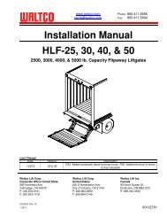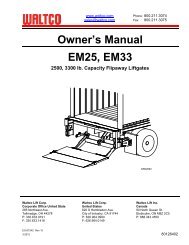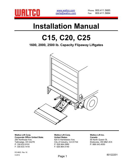
Installation Manual C15, C20, C25 - Waltco
Installation Manual C15, C20, C25 - Waltco
Installation Manual C15, C20, C25 - Waltco

You also want an ePaper? Increase the reach of your titles
YUMPU automatically turns print PDFs into web optimized ePapers that Google loves.
www.waltco.com Phone: 800.411.5685<br />
parts@waltco.com Fax: 800.411.5684<br />
<strong>Installation</strong> <strong>Manual</strong><br />
<strong>C15</strong>, <strong>C20</strong>, <strong>C25</strong><br />
1600, 2000, 2500 lb. Capacity Flipaway Liftgates<br />
<strong>Waltco</strong> Lift Corp. <strong>Waltco</strong> Lift Corp. <strong>Waltco</strong> Lift Inc.<br />
Corporate Office United State United States Canada<br />
285 Northeast Ave. 620 S Hambledon Ave. 90 North Queen St.<br />
Tallmadge, OH 44278 City of Industry, CA 91744 Etobicoke, ON M8Z 2C5<br />
P: 330.633.9191 P: 626.964.0990 P: 888-343.4550<br />
F: 330.633.1418 F: 626.964.0149<br />
EO:6823 Rev 16<br />
5-2012 80122201<br />
Page 1
Table of Contents<br />
Improper installation of this liftgate could result in severe personal injury or<br />
death.<br />
Read and understand the contents of these instructions before proceeding.<br />
When installed, this liftgate must not alter or prevent vehicle compliance to any<br />
existing state or federal standards.<br />
compliance.<br />
ommendations should be consulted for<br />
Introduction .....................................................................................................................3<br />
1. Safety Information................................................................................................................ 4<br />
2. Liftgate Terminology ............................................................................................................ 6<br />
3. Basic Mounting Requirements ............................................................................................. 9<br />
4. <strong>Installation</strong> ..........................................................................................................................11<br />
5. Placement of Decals...........................................................................................................29<br />
6. Lubrication Instructions.......................................................................................................30<br />
7. Final Inspection...................................................................................................................31<br />
8. How to Order Parts .............................................................................................................32<br />
9. Optional Kit Instructions:<br />
Hand Held Remote Kit.............................................................................................33<br />
Kit #80000430<br />
Aux Battery Kit (Truck) ............................................................................................34<br />
Kit #80001066<br />
Aux Battery Kit (Trailer) ...........................................................................................34<br />
Kit #80001069<br />
Tractor Wiring Kit ....................................................................................................39<br />
Kit #80000618<br />
Dual Control Kit .......................................................................................................40<br />
Kit #80000431<br />
Anti Theft Kit............................................................................................................41<br />
Kit #80001313<br />
Cab Shut-Off Kit......................................................................................................42<br />
Kit #80000827<br />
Rubber Snubber Kit.................................................................................................43<br />
Kit #80000421<br />
Remote Pump Mount Kit .........................................................................................44<br />
Kit #80000979<br />
Walk Ramp Install Kit ..............................................................................................45<br />
Kit #80000432<br />
Page 2
Introduction<br />
If anyone observes improper installation, improper operation, or damage, they should immediately<br />
contact a qualified person for assistance and correction. We strongly urge anyone that has any<br />
questions or doubts as to the installation, condition, use, operation, maintenance or repair of the liftgate<br />
to contact us at <strong>Waltco</strong> where we have qualified personnel that will be happy to assist you. Telephone<br />
Instructions.<br />
INSTALLATION<br />
<strong>Waltco</strong> liftgates should only be installed by those with sufficient basic skills to understand the<br />
installation and operation of the liftgate, along with the equipment on which the liftgate is being<br />
are given; however, it is the intent of these instructions to give the installer both the operations and<br />
what we believe to be the most desirable sequence of implementing these operations. These<br />
instructions can in no way expand into an area where they will replace a qualified person, or clear<br />
thinking and a basic knowledge that must be possessed by the installer.<br />
It has been our experience that a knowledgeable journeyman following these instructions and<br />
observing the operation of the liftgate will have a sufficient comprehension of the liftgate to enable this<br />
person to troubleshoot and correct all normal problems that may be encountered.<br />
Failure to follow the installation instructions, adjustments and mounting dimensions may result in<br />
improper and unsafe operation of the liftgate. Unauthorized alterations of the liftgate can cause an<br />
undesirable and dangerous condition.<br />
is no way intended to encourage usage or repair of the liftgate by those who are not qualified to do so.<br />
routine lubrication, parts lists, and an outline of things that should be checked but may not be obvious<br />
to those not technically qualified. This manual assumes the liftgate is properly installed, undamaged<br />
and operates correctly. Improper installation, improper operation, or damage should be immediately<br />
corrected by a qualified person.<br />
INSPECTION<br />
As part of the regular inspection of a liftgate and after damage or suspicion of an overload, inspect<br />
for wear or structural damage and make necessary repairs or replacements. Check all structural<br />
components and their attachment to the liftgate for cracked welds, loose fasteners, wear and part<br />
deformation. Check cylinder and hose for leaks. Inspections and repairs should be made by a qualified<br />
mechanic.<br />
REPLACEMENT PARTS<br />
Use only <strong>Waltco</strong> original equipment replacement parts. Components of other liftgate manufacturers<br />
may outwardly appear to be the same but are not interchangeable with <strong>Waltco</strong> products. <strong>Waltco</strong><br />
components are specifically designed for safety requirements, reliability and compatibility with our<br />
products. Refer to your <strong>Waltco</strong> parts manual when ordering parts. NOTE: When ordering, give model<br />
and serial number of liftgate.<br />
DECALS<br />
It is important that every vehicle that has a WALTCO Liftgate have legible DECALS clearly posted on<br />
d<br />
maintenance.<br />
an be obtained from WALTCO LIFT CORP.<br />
Page 3
Chapter 1<br />
Safety Information<br />
WARNING<br />
Read, understand, and follow all of the warning listed below.<br />
Failure to follow these warning could result in severe personal injury or death.<br />
Do not operate liftgate without a thorough knowledge and understanding of the operation of the liftgate.<br />
Liftgate hazards can result in crushing or falling.<br />
This liftgate is designed for loading and unloading of cargo. If personnel are required to ride liftgate, observe<br />
and familiarize yourself with the liftgate operation, decals and manuals. Ensure stable footing at all times.<br />
Do not ride liftgate with unstable loads.<br />
Wheeled loads must be properly retained from rolling.<br />
Tall, high center of gravity loads must be retained from falling over.<br />
Never overload liftgate:<br />
Load platform as close to the<br />
manual and capacity decal of liftgate for maximum load and load placement.<br />
Keep hands and feet clear of all potential pinch points.<br />
Never use liftgate if it makes any unusual noise, has unusual vibration, raises or lowers unevenly, or fails to<br />
operate smoothly.<br />
Never use liftgate if it shows any signs of structural damage such as cracked welds, bent or distorted<br />
members.<br />
Do not attempt any repairs unless you are qualified to do so. Care should be taken when work is performed<br />
on a disabled liftgate located near moving traffic. When possible the vehicle should be moved away from<br />
traffic areas for repair. Precautionary measures should be taken to ensure personal safety including those<br />
recommended in Federal Motor Vehicle Safety Standards 571.125.<br />
When welding to liftgate, or liftgate components, take all necessary safety precautions, including using<br />
respiratory protection and other pertinent personal protective gear when welding harmful materials.<br />
All protective covers, guards, and safety devices must be in place and access doors closed before operating<br />
liftgate.<br />
Do not allow anyone to stand in, or near area, in which Platform will open and close before opening or closing<br />
Platform.<br />
Do not allow anyone to stand near the Platform where a falling load could land on them.<br />
Take care to retain cargo during transit for liftgate Platforms which function as the tailgate or door of the cargo<br />
area. Small objects can fall through the space between the vehicle and the folded Platform.<br />
A Lock-Out device or Shut-Off Switch should always be used to prevent unauthorized use of liftgate.<br />
For liftgates with Runners, never use liftgate if Runners do not travel freely and smoothly.<br />
For liftgates with Roller Lifting Chain, the Chain should be replaced every (5) five years or 15,000 cycles,<br />
whichever comes first. Replace only with <strong>Waltco</strong> approved Roller Chain.<br />
Never transfer loads which exceed lifting capacity on or over any part of the Platform unless the liftgate is<br />
equipped with a special reinforced Platform and Platform Support Bars for use when the Platform is used as<br />
loading ramp (dock board). Refer to th<br />
For liftgates equipped with Trailer Hitches, never exceed the rated capacity of the hitch. Do not exceed the<br />
Vehicle must comply with all state and federal standards.<br />
Page 4
Liftgates with Tilt Function<br />
Proper use of the Control Switches is of extreme importance.<br />
Improper use of Tilt Switch could cause load to fall from the Platform or damage the liftgate.<br />
Platform should be in a generally horizontal position when raising or lowering with a load.<br />
In any tilt position, the Platform may vary from level while raising or lowering the Platform.<br />
Liftgates equipped with spring operated Cam Closer<br />
Replace Cam Release Spring every five (5) years or 15,000 cycles, whichever comes first.<br />
RGL-Series Liftgates<br />
Make certain Platform Brake mechanisms are operating properly.<br />
The Runners are always to remain powered up against the Up-stops Pins when in transit.<br />
Inspect Cables every three (3) months or 750 cycles, whichever comes first. Cables must be replaced if they<br />
show signs of wear, distortion, kinking or if any broken wires are visible<br />
Replace cables every five (5) years or 10,000 cycles, whichever comes first.<br />
This is the safety alert symbol. This manual uses this symbol to alert you to potential personal injury<br />
hazards.<br />
Obey all safety messages that follow this symbol to avoid personal injury or death.<br />
SIGNAL WORDS<br />
WARNING<br />
Indicates a potentially hazardous situation, which if not<br />
avoided, could result in death or serious injury.<br />
Black letters on an orange background<br />
CAUTION<br />
Indicates a potentially hazardous situation, which if not<br />
avoided, may result in minor or moderate injury. May<br />
also be used to alert against unsafe practices.<br />
Black letters on a yellow background.<br />
NOTICE<br />
Indicates a potentially hazardous situation, which if not<br />
avoided, may result in property damage.<br />
WARNING<br />
CAUTION<br />
NOTICE<br />
Page 5
Chapter 2<br />
Liftgate Terminology<br />
1. Hydraulic Cylinder<br />
2. Hose Assembly<br />
3. Return Line Barbed Fitting<br />
4. Return Line<br />
5. Breather<br />
6. Lowering Solenoid<br />
7. Pump Unit Starter Solenoid<br />
8. Pump Unit Motor<br />
9. Pump Unit Reservoir<br />
10. Hose fitting<br />
11. Pressure Compensative Flow Control Valve<br />
12. Drain Plug<br />
Gravity Down<br />
Power Down<br />
(optional)<br />
GR02594<br />
Page 6
Chapter 2<br />
Liftgate Terminology<br />
15. Transit Chain<br />
16. Pump Unit Cover<br />
17. Dock Bumper<br />
18. Mount Tube Assembly<br />
19. Parallel Arm Assembly<br />
20. Lift Arm Assembly<br />
21. Platform Deck Assembly<br />
22. Platform Extension Assembly<br />
23. Parting Bar<br />
24. Specification Tag<br />
25. Transit Chain Lug<br />
26. Bed Extension<br />
27. Hydraulic Pump Unit<br />
GR02557<br />
Page 7
Chapter 2<br />
Liftgate Terminology<br />
Explanation of Specification Tag<br />
Model Description Capacity<br />
<strong>C15</strong> SB Standard Bed Height 1600 lbs.<br />
<strong>C15</strong> HB High Bed Height 1600 lbs.<br />
<strong>C20</strong> SB Standard Bed Height 2000 lbs.<br />
<strong>C20</strong> HB High Bed Height 2000 lbs.<br />
<strong>C25</strong> HB High Bed Height (Only) 2500 lbs.<br />
MODEL NUMBER<br />
RATED CAPACITY<br />
Based on an evenly<br />
distributed load on the<br />
platform flat surface.<br />
SERIAL NUMBER<br />
of liftgate. To be used<br />
when ordering parts or<br />
when contacting <strong>Waltco</strong><br />
for service or warranty<br />
questions<br />
DATE OF<br />
MANUFACTURE<br />
Month / Year<br />
GR00241<br />
GR02558<br />
Page 8
Chapter 3<br />
BASIC MOUNTING REQUIREMENTS<br />
Measure distance from ground to floor level. This is<br />
the bed height.<br />
Refer to bed height dimension on mounting chart<br />
minimum mount frame clearance required.<br />
NOTE:<br />
Max bed height dimensions for unloaded vehicle.<br />
Min bed height dimensions for fully loaded vehicle<br />
NOTE:<br />
and mount frame.<br />
Bed Height<br />
(Ground to Floor)<br />
GR00139<br />
C-15 SB & C-20 SB<br />
STANDARD BED HEIGHT MODELS<br />
Bed<br />
Height<br />
Ground<br />
Clearance<br />
Dimension<br />
Mount<br />
Frame<br />
Clearance<br />
Notch<br />
Height<br />
Max.<br />
Sill<br />
Height<br />
Max.<br />
Dimension<br />
GR02529<br />
Dimension<br />
- 16<br />
-<br />
-<br />
- 12<br />
C-15 HB & C-20 HB<br />
HIGH BED HEIGHT MODELS<br />
Bed<br />
Height<br />
Ground<br />
Clearance<br />
Dimension<br />
Mount<br />
Frame<br />
Clearance<br />
Notch<br />
Height<br />
Max.<br />
Sill<br />
Height<br />
Max.<br />
Dimension<br />
GR02829<br />
Dimension<br />
-<br />
-<br />
C-25 HB<br />
HIGH BED HEIGHT MODELS<br />
Bed<br />
Height<br />
Ground<br />
Clearance<br />
Dimension<br />
Mount<br />
Frame<br />
Clearance<br />
Notch<br />
Height<br />
Max.<br />
Sill<br />
Height<br />
Max.<br />
Dimension<br />
GR02829<br />
Dimension<br />
- 16 16<br />
42 -47 21 33¾ ---- 4½ 18 12<br />
Page 9
Chapter 3<br />
BASIC MOUNTING REQUIREMENTS<br />
13-1/8<br />
A<br />
72-5/8<br />
26-1/8<br />
46-1/2<br />
23-7/8 37-1/8<br />
22-1/8<br />
7<br />
7-1/4<br />
Ground<br />
Clearance<br />
8-3/8<br />
Mount frame<br />
Clearance (Ref.)<br />
Page 10
Chapter 4<br />
<strong>Installation</strong><br />
PREPARATION OF BODY SILL<br />
Remove all obstructions that would interfere with<br />
operation of Liftgate; such as dock bumpers, trailer<br />
hitches, projections, etc.<br />
Locate and mark the center of body sill.<br />
NOTE:<br />
All mounting measurements for centering liftgate<br />
will come from centerline mark.<br />
Body sill must have clearances indicated. Cut or notch<br />
Rear Sill to obtain these clearances.<br />
Refer to chart p. 3-1<br />
Maximum<br />
Notch<br />
Height<br />
Maximum<br />
Sill Height<br />
45 deg TYP<br />
Cut away vehicle frame as required to obtain the<br />
minimum clearance indicated.<br />
Floor Level<br />
Maximum<br />
Sill Height<br />
GR02126<br />
Y<br />
X<br />
GR02127<br />
strap.<br />
Body Crossmember<br />
Vehicle Frame<br />
steel strap<br />
GR00625<br />
Page 11
Chapter 4<br />
<strong>Installation</strong><br />
INSTALLATION OF BED EXTENSION<br />
Place two Support Gussets on rear sill as shown.<br />
Hanger Tabs<br />
Gusset<br />
Tack weld Gussets to sill.<br />
NOTE:<br />
Do not weld hanger tabs to sill!<br />
Break off Hanger Tabs<br />
Approx.<br />
Approx.<br />
GR00144<br />
Place Bed Extension on Gussets and center Bed<br />
Extension with sill.<br />
(Two raised round spots on surface of diamond<br />
plate indicate centerline.)<br />
Weld Bed Extension to sill as shown.<br />
NOTE:<br />
Be certain centerline of body sill and centerline of<br />
bed extension are in line.<br />
gusset and end bar.<br />
GR02559<br />
Weld the two Support Gussets to Bed Extension and<br />
weld all gussets to sill as shown.<br />
NOTE:<br />
When irregular sill exists, cut or shim gussets<br />
to maintain a level attitude of bed extension<br />
with floor of body.<br />
Weld two support gussets<br />
of each.<br />
around three<br />
sides of<br />
each bar.<br />
of every gusset.<br />
GR02560<br />
Bolt Transit Chain to Bed Extension with 3/8-16 x 1-1/4<br />
Grade 8 bolt, Washer and Hex Locknut as shown.<br />
GR02569<br />
Page 12
Chapter 4<br />
<strong>Installation</strong><br />
Position liftgate up under vehicle.<br />
Using a forklift or crane, raise platform up to bed<br />
extension.<br />
Butt platform and bed extension skins together.<br />
Platform to be centered on vehicle.<br />
A jack, or come-a-long, can be used to position mount<br />
tube to proper A-Dimension.<br />
Be sure platform is centered on vehicle body and bed<br />
extension.<br />
Bed Extension<br />
Other means may be used to support<br />
Liftgate in position. ALWAYS verify the<br />
safety of your supporting method before<br />
proceeding.<br />
Centerline of body, bed<br />
extension and platform<br />
Platform<br />
Bed Extension<br />
Dimension<br />
GR02659A & 2651A<br />
Page 13
Chapter 4<br />
For C-15 and C-20 Only<br />
Assemble supports, using channels or tubes as<br />
supports, and rest them on 1" spacers as shown.<br />
Position deck centrally to and tight against bed<br />
extension and clamp securely to supports.<br />
Raise<br />
Rotate mount tu<br />
hinge assembly and platform stops are snug<br />
Other means may be used to support<br />
Mount Frame in position. ALWAYS verify<br />
the safety of your supporting method<br />
before proceeding.<br />
NOTE:<br />
Pump box end cover orientation may vary from<br />
horizontal up to 3 degrees rotation in either<br />
direction. This is normal. Amount of rotation will<br />
vary with bed height and mounting dimensions.<br />
<strong>Installation</strong><br />
il<br />
Platform Stop<br />
Supports<br />
Hinge<br />
Assembly<br />
Mount Tube<br />
lbs.<br />
Dimension<br />
GR01901A<br />
For C-25 Only<br />
The C-25 liftgate has platform adjusting bolts as shown.<br />
<strong>Installation</strong> is different, see below.<br />
Never get under platform to adjust bolts..<br />
Platform Adjustment Bolts<br />
GR02906<br />
For C-25 Only<br />
Assemble supports, using channels or tubes as<br />
supports, do not use spacers.<br />
Position deck centrally to and tight against bed<br />
extension as shown and clamp securely to supports.<br />
Supports<br />
No Spacers<br />
lbs.<br />
Raise mount tube into position to hold<br />
Rotate mount tube so pump bracket and cover are<br />
parallel to the ground.<br />
Platform<br />
Adjusting Bolt<br />
Hinge<br />
Assembly<br />
Dimension<br />
Other means may be used to support<br />
Mount Frame in position. ALWAYS verify<br />
the safety of your supporting method<br />
before proceeding.<br />
Mount Tube<br />
Pump Cover<br />
Parallel<br />
w/Ground<br />
NOTE:<br />
Platform angle will be adjusted later.<br />
GR01901B<br />
Page 14
Chapter 4<br />
MOUNT PLATE INSTALLATION<br />
Locate mount plates on mount tube. Mount plates<br />
should be approximately 90° to vehicle frame.<br />
Check that mount plates extend a minimum of 5-1/4"<br />
above bottom of vehicle frame. If dimension cannot be<br />
held, refer to the optional installation.<br />
See below for additiona<br />
A-Dimension on C-25 liftgates.<br />
<strong>Installation</strong><br />
sides of mount plates<br />
Shield all wires and hoses from heat and<br />
weld splatter.<br />
5-<br />
Mount<br />
Plate<br />
plates 100% to vehicle frame with 1/4<br />
Weld mount tube to the mount plates. Weld all around,<br />
both sides of the mount plates, and ends, with 1/4" weld.<br />
To avoid injury or property damage, do not<br />
remove<br />
clamps from deck. Use forklift, crane, or<br />
other safe<br />
means to support deck and then remove<br />
clamps.<br />
Mount Tube<br />
both sides and ends of mount<br />
plates<br />
GR00472A<br />
MOUNT PLATE INSTALLATION<br />
C- -DIMENSION<br />
Note how chassis frame cutout falls in relation to mount<br />
plate.<br />
Weld back side of mount plate<br />
weld x 100%<br />
Chassis frame<br />
cutout falls behind<br />
mount plate<br />
GR00472B<br />
Page 15
Chapter 4<br />
OPTIONAL INSTALLATION<br />
If the 5-<br />
plate must be added.<br />
<strong>Installation</strong><br />
1/4<br />
sides of mount plates and<br />
adapter plates as shown.<br />
Shield all wires and hoses from heat and<br />
weld splatter.<br />
5-<br />
Min.<br />
1/4<br />
Weld mount tube to mount plates. Weld all around, both<br />
sides of mount plates, and ends, with 1/4" weld.<br />
To avoid injury or property damage, do not<br />
remove<br />
clamps from deck. Use forklift, crane, or<br />
other safe<br />
means to support deck and then remove<br />
clamps.<br />
5-<br />
Min.<br />
adapter<br />
plate<br />
1/4<br />
around both sides and<br />
ends of mount plates.<br />
GR00473<br />
NOTE:<br />
If necessary, liftgate may be mounted to inside of<br />
frame as shown.<br />
Truck Frame<br />
5-<br />
Weld channel<br />
to Truck Frame<br />
with weld.<br />
Weld 100% all<br />
around as<br />
shown.<br />
3<br />
Weld Mount Plate to<br />
channel with 1/4<br />
after channel is welded<br />
to the Truck Frame.<br />
GR01713<br />
Page 16
Chapter 4<br />
INSTALLATION OF CONTROLS<br />
Locate Switch such that, when operating liftgate,<br />
operator will have clear view of entire platform area<br />
and will not be in area that liftgate will pass through.<br />
Install Switch Mounting Template Decal (or use this<br />
diagram). Locate screw holes. Drill four (4) holes with<br />
a #26 (0.147"dia.) drill bit.<br />
<strong>Installation</strong><br />
1.75<br />
Hole for<br />
Control Cord<br />
(optional)<br />
NOT ACTUAL SIZE<br />
Dia. Hole<br />
GR02181<br />
If Control Cord will be run through a hole in rear of body,<br />
remove all sharp edges from hole and insert a grommet.<br />
Use #8 Self-tapping Screws to secure switch.<br />
#8 Self-<br />
Tapping<br />
Screws<br />
GR02561<br />
Route Control Cord from Switch to Pump Plate.<br />
Install grommets (supplied) as shown on Control Cord<br />
and Battery Cable. Secure cables to vehicle with cable<br />
ties provided.<br />
Connect Control Cord and Battery Cable to pump as<br />
shown. Connectors are gendered to allow only correct<br />
connections.<br />
Add generous amount of dielectric grease to all<br />
electrical terminals and connections.<br />
NOTE:<br />
Do not connect battery cable to battery at this time.<br />
GREEN<br />
POWER<br />
WHITE<br />
RAISE<br />
BLACK<br />
LOWER<br />
GR02000<br />
Page 17
Chapter 4<br />
INSTALLATION OF POWER CABLE<br />
Locate and mount 150 Amp circuit breaker directly to<br />
batteries using copper terminal link supplied.<br />
Circuit breaker must be mounted to give good protection<br />
against any objects coming into contact with circuit<br />
breaker terminals and causing a short. Position must<br />
also be readily accessible to reset breaker.<br />
NOTE:<br />
Circuit Breaker is to rest solidly on battery<br />
to prevent vibration during transit.<br />
If unable to connect circuit breaker direct to batteries,<br />
may be used.<br />
Connect end of battery cable from liftgate to Terminal<br />
Link attached to circuit breaker.<br />
Apply a generous amount of Dielectric Grease to all<br />
Battery terminals and Circuit Breaker terminals.<br />
Secure all battery cables to chassis frame with cable<br />
ties provided.<br />
IMPORTANT:<br />
Original equipment ground cable furnished on<br />
vehicle should be at least a number 2 ga. to insure<br />
proper operation of pump unit. An auxiliary ground<br />
cable should be added between engine block and<br />
chassis frame if engine is not adequately grounded<br />
to chassis frame. When there are two or more<br />
batteries, all cables connecting batteries together<br />
must be 2 ga. or heavier. This includes all original<br />
equipment batteries on vehicle.<br />
Protect wires from any sharp edges or<br />
holes that may abrade insulated covering<br />
of wires.<br />
<strong>Installation</strong><br />
150 Amp Circuit Breaker<br />
Battery Cable<br />
From Liftgate<br />
Copper Terminal Link<br />
Secure battery cable so it does not come<br />
near, or in contact with, other vehicle<br />
wiring, fuel lines, brake lines, air hoses,<br />
exhaust system, etc.<br />
GR00080<br />
Page 18
Chapter 4<br />
DIVERT WATER FROM ENCLOSURE<br />
<strong>Installation</strong><br />
Zip Tie<br />
To help prevent channeling water into pump or battery<br />
enclosures:<br />
Secure hoses, cables and cords downward as<br />
they exit the enclosure.<br />
If a downward exit is impractical, a Zip Tie can<br />
be installed around hose or cable to help<br />
interrupt the flow of water as shown.<br />
Flow of water<br />
Pump or Battery<br />
Enclosure<br />
GR02460<br />
Basic gravity down liftgate wiring<br />
GR01994<br />
Hydraulic Schematic<br />
Gravity Down<br />
Hydraulic Cylinder<br />
Lowering Speed Flow<br />
Control Valve (pressure<br />
compensative, nonadjustable)<br />
Pump/Reservoir<br />
Lowering<br />
Solenoid<br />
Valve<br />
GR02595<br />
Page 19
Chapter 4<br />
Basic power down liftgate wiring<br />
<strong>Installation</strong><br />
GR02904<br />
Hydraulic Schematic<br />
Power Down<br />
Lowering Speed Flow<br />
Control Valve (pressure<br />
compensated)<br />
Hydraulic Cylinder<br />
Lowering Solenoid<br />
Valve<br />
Pump/Reservoir<br />
Raise<br />
Solenoid<br />
Valve<br />
GR02596<br />
Page 20
Chapter 4<br />
HOSE INSTALLATION<br />
Avoid twisting of hoses.<br />
Avoid sharp bends when routing hoses<br />
Hoses will contract under pressure. Allow plenty of<br />
slack between connecting points.<br />
Do not clamp hoses at bends to allow for length<br />
changes when hose is pressurized.<br />
<strong>Installation</strong><br />
High Pressure<br />
No Pressure<br />
GR00717<br />
FILLING HYDRAULIC RESERVOIR<br />
Position liftgate deck per chart below (use forklift,<br />
crane, or other safe device).<br />
Remove Reservoir Plug.<br />
of reservoir.<br />
If low, fill as required. Use appropriate fluid per chart.<br />
Replace Plug.<br />
Run liftgate full cycle several times to release trapped<br />
air from system.<br />
Plug<br />
GR02130<br />
LIFTGATE POSITION FOR OIL LEVEL CHECK<br />
Gravity Down Pump:<br />
Power Down Pump:<br />
Deck should be in this position:<br />
Ground Level<br />
Bed Level<br />
Recommended Fluids<br />
Fill reservoir<br />
Temperature Range Acceptable Fluids Fill with recommended fluid or equivalent.<br />
0 to 120 F <strong>Waltco</strong> Biodegradable<br />
Liftlube TM part #85803860<br />
F<br />
Fluids are available from the <strong>Waltco</strong> parts<br />
Shell Tellus S2 V 32<br />
Dept. 1-800-411-5685 www.waltco.com<br />
Chevron AW32<br />
-20 to 90 F <strong>Waltco</strong> Biodegradable<br />
LiftLube Arctic part<br />
#85803866<br />
NOTE:<br />
Do not use the following fluids:<br />
Shell Tellus S2 V 15<br />
Mobil DTE 13<br />
Brake Fluid<br />
Power steering fluid<br />
MIL H - 5606<br />
Automatic Transmission Fluid (ATF)<br />
A good quality SAE 10W motor oil may also be used in<br />
temperatures above 32 F.<br />
Page 21
Chapter 4<br />
There is no speed adjustment on this liftgate.<br />
Lowering speed is controlled by the pressure<br />
compensative valve plumbed at the cylinder.<br />
Regardless of weight on platform, liftgate should lower<br />
at approximately six (6) inches per second.<br />
<strong>Installation</strong><br />
Bed Height (inches)<br />
6<br />
= Lowering Time (seconds)<br />
This liftgate must have the correct<br />
pressure compensative valve installed:<br />
7010001-12<br />
Pressure Compensative<br />
Flow Control Valve<br />
GR02597<br />
Page 22
Chapter 4<br />
<strong>Installation</strong><br />
For C-25 Only<br />
ADJUST PLATFORM ANGLE<br />
Lower platform until stop blocks hit ground.<br />
Tip of platform should touch ground without platform<br />
breaking (starting to fold) as shown in top drawing.<br />
Properly adjusted<br />
platform<br />
If platform tip is off the ground, adjust platform down<br />
until it reaches ground.<br />
If platform tip reaches ground before stop blocks, and<br />
platform starts to fold, adjust platform up.<br />
Be sure both adjusting bolts are adjusted the same.<br />
Never get under platform to adjust bolts.<br />
Platform off ground<br />
adjust platform down<br />
Platform breaking<br />
adjust platform up<br />
Stop Block<br />
Always secure jam nuts after any<br />
adjustment is made.<br />
Raise platform back to bed level to check kick-up of<br />
platform.<br />
Initial kick-<br />
4- er bed heights.<br />
Platform Adjusting Bolt<br />
If kick-up is too little, or too great for specific<br />
application, adjust angle of platform as required.<br />
For additional assistance contact <strong>Waltco</strong> Tech Support.<br />
Kick-up of platform<br />
GR02816 GR02817<br />
Page 23
Chapter 4<br />
<strong>Installation</strong><br />
INSTALLATION OF PARTING BAR<br />
To assist the opening of the platform:<br />
Locate and position the parting bar using the appropriate diagram below.<br />
Tack weld in place.<br />
Check the opening and closing operation of the platform.<br />
Weld the parting bar to the mount tube 100% at all points of contact with 1/4<br />
C-15 & C-20 Only<br />
Note position<br />
of flat bar<br />
GR01789<br />
C-25 Only<br />
Parting Bar<br />
For<br />
-Dimension<br />
For: 21-<br />
-Dimension<br />
Note position<br />
of flat bar<br />
GR01791<br />
C-25 Only<br />
Parting Bar<br />
For<br />
-Dimension<br />
For: 21-<br />
42<br />
-Dimension<br />
Note position<br />
of flat bar<br />
GR01792<br />
Page 24
Chapter 4<br />
NOTE:<br />
If properly installed, skid plate will ride on<br />
parting bar when platform is opening.<br />
<strong>Installation</strong><br />
Skid<br />
Plate<br />
Platform Deck<br />
Platform Extension<br />
GR01906<br />
ACTIVATION OF FOLD OVER ASSIST SPRING<br />
With hinge (1) half way to ground and platform (4)<br />
resting on parting bar, drive coiled pin (2) through<br />
hinge pin (3).<br />
Check to ensure that torsion spring contacts coiled<br />
pin (2) when platform is rotated to vertical position.<br />
GR01725<br />
INSTALLATION OF UPSTOPS<br />
Purpose of up-stops is to prevent excessive bowing of<br />
bed extension when platform is powered up against<br />
extension.<br />
Stored position up-stop<br />
Bed Extension<br />
Hinge Assembly<br />
Fold platform to stored position and using Raise Switch,<br />
bed extension as shown.<br />
Upstop<br />
Position up-stop along outside of truck frame as shown.<br />
Only one up-stop is required.<br />
NOTE:<br />
Use up-stop supplied in parts box or use a piece<br />
of channel, angle, or bar stock. Up-stop should<br />
Tack weld up-stop in place. Check to make sure<br />
Up-stop does not interfere with opening or folding<br />
of platform before finish welding.<br />
Upstop should be located<br />
above deck tube.<br />
Weld upstop to truck frame only.<br />
GR02132<br />
Page 25
Chapter 4<br />
Open position up-stop<br />
NOTE:<br />
This up-stop is optional and only required if bed<br />
extension bows when platform is powered up<br />
against it while in the open (loading) position.<br />
With platform in the open position and using<br />
Raise Switch, raise platform to within 1/16"<br />
of bed extension as shown below.<br />
<strong>Installation</strong><br />
Up-stop<br />
Bed<br />
Extension<br />
(approx.)<br />
Platform<br />
Side Bar<br />
Up-stop to<br />
contact Side<br />
Bars<br />
GR01732<br />
NOTE:<br />
Upstock.<br />
Bed Extension<br />
Locate and weld up-stops to underside of bed<br />
extension. Up-stops are to contact the platform side<br />
bars on each side of platform.<br />
Upstop<br />
Platform<br />
Side Bar<br />
GR02562<br />
INSTALLATION OF DOCK BUMPERS<br />
Grind corners of bed extension as required for proper<br />
fit of dock bumper angles.<br />
Locate and weld dock bumper angles against outer<br />
edge of bed extension and snug up against underside<br />
of bed extension, 3/16" weld 100% as shown below.<br />
Position support bar as shown holding bar tight<br />
against sill. Weld 3/16" welds as shown to cross<br />
members and sill.<br />
Position support channel as shown holding channel<br />
tight against bumper angle and support bar.<br />
Weld 3/16" welds as shown.<br />
Install optional rubber bumper if ordered. Install optional<br />
step if desired by welding a 3/8" x 3" x 9-1/2"lg. bar<br />
between support channel and bumper angle as shown.<br />
3/16" weld<br />
Rubber<br />
Bumper<br />
3/16" weld<br />
Support Bar<br />
3/16" weld<br />
Support<br />
Channel<br />
Optional Step<br />
(not included in kit)<br />
3/16" weld<br />
Cross<br />
Member<br />
3/16" weld<br />
Bumper Angle<br />
GR02563<br />
Page 26
Chapter 4<br />
OPTIONAL SUPER DUTY DOCK BUMPER<br />
INSTALLATION.<br />
Position bumper assemblies as shown. Top of bumper<br />
assemblies to be flush with top of bed extensions.<br />
Weld into place with 3/16" weld as shown.<br />
Weld support gussets to bumper assembly and to<br />
cross members as shown below.<br />
<strong>Installation</strong><br />
weld 100%<br />
both sides<br />
Sill<br />
Cross Member<br />
Support<br />
Gusset<br />
welds as<br />
shown<br />
GR02564<br />
OPTIONAL DOCK BUMPER AND TAILLIGHT<br />
INSTALLATION<br />
Position bumper assemblies as shown.<br />
Weld into place with 3/16" fillet weld as shown.<br />
Weld support gussets to bumper assembly and to<br />
cross members as shown.<br />
100%<br />
Support<br />
Gusset<br />
GR01339<br />
Page 27
Chapter 4<br />
LIGHT INSTALLATION<br />
Install lights and rubber bumpers (if ordered) using<br />
parts and fasteners provided.<br />
<strong>Installation</strong><br />
Hex Nut<br />
Machine Screw<br />
Taillight Bracket<br />
Dock Bumper Assembly<br />
Harness, 2 lamps<br />
Light grommet<br />
Taillight,<br />
White back-up<br />
Taillight,<br />
Red S, T&T<br />
Rubber Bumper<br />
Hex Nut welded<br />
inside dock bumper<br />
GR02089<br />
<strong>Waltco</strong> offers three suggestions for the installation of the<br />
vehicle taillights. We believe these suggested locations<br />
meet D.O.T. regulations but do not warrant that they do.<br />
Your installation of the vehicle taillights should meet all<br />
applicable regulations and requirements. This is in no<br />
way to infer that these suggestions are the only correct<br />
method of installing taillights.<br />
skin, if there is sufficient room.<br />
the body rear corner posts.<br />
bumpers available that<br />
have lights included as part of the dock bumper.<br />
NOTE:<br />
Original equipment lights may not provide sufficient<br />
clearance at this location so a narrower light may be<br />
required.<br />
All lights must be installed in accordance<br />
with all applicable D.O.T. regulations.<br />
GR02503<br />
Page 28
02-09<br />
TRANS IT<br />
CHAIN<br />
8010151<br />
7<br />
Chapter 5<br />
Placement of Decals<br />
All decals must be in place and legible or all warranties are void.<br />
ITEM DECAL QTY PART NO. LOCATION<br />
1<br />
2<br />
Safety Instructions 1 80100850 Locate in a conspicuous place near controls.<br />
Operation 1 80101528<br />
Hazard Decal 1 80101370 If your liftgate is equipped with dual<br />
controls, an additional Safety Instruction<br />
Important Decal 1 80100828 decal (80100850) is to be placed in a<br />
Motor Thermal Switch 1 80101480 conspicuous place near the second set of<br />
controls.<br />
Stand Clear Decal 1 75089296<br />
<strong>C15</strong> 1600 lb 1 80100252<br />
<strong>C20</strong> 2000 lb 1 80100253<br />
<strong>C25</strong> 2500 lb 1 80100255<br />
Use Handle Decal 1 75089295<br />
Stand Clear Decal 1 75089296<br />
<strong>C15</strong> 1600 lb 1 80100252<br />
<strong>C20</strong> 2000 lb 1 80100253<br />
<strong>C25</strong> 2500 lb 1 80100255<br />
3 Store Tight Decal 1 80101517<br />
4 Circuit Breaker Decal 1 80100829<br />
5 Stand Clear Decal 1 75089296 Locate<br />
Refer to the following diagram showing decal locations.<br />
Locate near platform handle<br />
(positioned so as to be read when platform<br />
is being unfolded into loading position)<br />
Locate on back of deck on curb side<br />
(visible when platform is stored)<br />
Locate next to liftgate circuit breaker.<br />
In applications where more than one circuit breaker<br />
is used, this decal must be placed in both locations<br />
To maximize decal adhesion to surfaces:<br />
Surface must be dry and clean<br />
Firm pressure must be applied to decal<br />
Minimum surface temperature 65º<br />
Heat gun may be used to heat surface<br />
GR02565<br />
Page 29
Chapter 6<br />
Lubrication Instructions<br />
The liftgate should be lubricated every 120 days.<br />
There are no grease fittings provided on the liftgate.<br />
#1 Oil with a light weight machine oil (do not use oil on bearings in arms or cylinder).<br />
#2 These are bearings that do not require grease, however, bearing can be sprayed with a non-petroleum<br />
based lubricant such as Zep-45 to retard corrosion of pins, reduce friction, and increase life of bearings<br />
GR02566<br />
Page 30
Ch 7.<br />
FINAL INSPECTION SHEET<br />
IMPORTANT:<br />
All of the following are to be checked and verified<br />
before installation is complete.<br />
A. Is grade 8 bolt installed through collar and<br />
lower cylinder pin and retained with selflocking<br />
nut<br />
S. Are all decals properly in place and legible<br />
according to the decal placement drawings<br />
T. Is pump cover installed and securely<br />
latched<br />
U.<br />
B. Are all roll pins securely in place<br />
C. Are all fasteners tight<br />
D. Does liftgate fold and unfold properly<br />
E. Does the platform meet the bed extension<br />
properly<br />
F. Does transit chain properly hook onto transit<br />
chain lug<br />
G. Do controls operate properly<br />
H. Are bed extension, mount frame, mount<br />
plates, up-stops, dock bumpers, bumper<br />
braces, taillight guards and taillights all<br />
finish welded<br />
I. Are hydraulic hoses and fittings properly<br />
connected with no leaks<br />
J. Verified correct pressure compensative<br />
valve is installed<br />
K. Is battery cable attached and clamped<br />
tight<br />
L. Is 150 amp circuit breaker installed at<br />
battery<br />
M. Are all electrical connections coated with<br />
dielectric grease<br />
N. Has hydraulic system been properly bled<br />
of all air<br />
O. Is pump reservoir full of oil<br />
P. Are all parts properly lubricated according<br />
to the lubrication instructions<br />
Q. Do lights operate properly<br />
(Note: Lights must be installed in<br />
accordance with all applicable state<br />
and federal D.O.T. regulations)<br />
R. Is license plate properly installed<br />
Do not use liftgate if any of the above are not<br />
checked and verified. If you have any questions<br />
not covered in this manual, contact your nearest<br />
<strong>Waltco</strong> distributor, or the nearest <strong>Waltco</strong><br />
factory.<br />
Page 31
How To Order Parts<br />
Repairs should be made only by authorized mechanics using WALTCO<br />
Replacement parts.<br />
When ordering repair or replacement parts, please include all the information<br />
asked for below. If this information is not available, a complete written description<br />
or sketch of the required part will help WALTCO identify and deliver the needed<br />
part to you.<br />
________________________________________________________________<br />
THE FOLLOWING INFORMATION MUST BE INCLUDED:<br />
1. SERIAL NUMBER - [WALTCO liftgate serial numbers can be found on the<br />
Specification Tag attached to the mount frame.]<br />
2. MODEL NUMBER<br />
3. CAPACITY<br />
4. PLATFORM SIZE<br />
________________________________________________________________<br />
THEN INCLUDE THE FOLLOWING INFORMATION:<br />
5. PART NUMBERS<br />
6. DESCRIPTION<br />
7. QUANTITY REQUIRED<br />
________________________________________________________________<br />
MAIL, E-MAIL OR PHONE YOUR REQUEST TO:<br />
<strong>Waltco</strong> Lift Corp<br />
285 Northeast Avenue<br />
Tallmadge, OH 44278<br />
1-800-411-5685<br />
FAX: 1-800-411-5684<br />
E-MAIL: parts@waltco.com<br />
ALL PARTS ARE F.O.B. FROM THE SHIPPING FACTORY<br />
________________________________________________________________<br />
PLEASE NOTE:<br />
To assure you of continuing and effective quality control, our warranty policy<br />
permits replacement of hydraulic cylinders, valves and motor pump units when<br />
their factory seals are intact. Parts under warranty will be exchanged promptly<br />
after careful inspection of the returned assemblies.<br />
________________________________________________<br />
Page 32
Hand Held Remote <strong>Installation</strong><br />
DRILL SOCKET HOLES<br />
Using dimension shown, drill mounting<br />
holes in desired location for socket.<br />
1-<br />
GR00036<br />
INSTALL SOCKET<br />
Assemble socket as shown.<br />
Install wires according to colors:<br />
W = White (Raise)<br />
B or BK = Black (Lower)<br />
G = Green (Power)<br />
GR02240<br />
CONNECT WIRES TO PUMP UNIT<br />
This step is for most liftgates, see next<br />
page for MDL series liftgate instructions.<br />
Route Control Cord into pump enclosure.<br />
First connect Pump wires to Dual Control<br />
Adapter Harness as shown.<br />
Connect both Control Cords to other ends of<br />
Adapter Harness as shown.<br />
Note!<br />
Match wire connections male to female. Color<br />
of wire may vary.<br />
CONTROL<br />
CORD<br />
ADAPTOR<br />
HARNESS<br />
CONTROL<br />
CORD<br />
SOCKET<br />
GR02082<br />
80101485 EO6447 Rev.04<br />
Page 33
BATTERY KIT INSTALLATIONS 80101387<br />
DETERMINE BATTERY AND PUMP LOCATION, AND<br />
CABLE ROUTING<br />
Determine where pump unit and battery box will be<br />
located. Make certain hydraulic hoses supplied will<br />
reach pump.<br />
Your installation may use only one cable supplied with<br />
liftgate, or, it may also use a cable supplied with the<br />
trailer kit.<br />
Truck with auxiliary batteries:<br />
Cable supplied with liftgate will be cut into two lengths to<br />
reach from pump to auxiliary batteries and to vehicle<br />
batteries.<br />
PUMP<br />
AUXILIARY<br />
BATTERY<br />
VEHICLE<br />
BATTERY<br />
Trailer with auxiliary batteries:<br />
Use cable supplied with liftgate from pump to auxiliary<br />
batteries.<br />
Use cable supplied with trailer kit from auxiliary batteries<br />
to nose of trailer.<br />
Note: Auxiliary batteries on trailers are to be<br />
-<br />
GR01389<br />
Page 34<br />
EO6410 Rev 04<br />
7-22-10
BATTERY KIT INSTALLATIONS 80101387<br />
BATTERY AND PUMP BOX INSTALLATION<br />
Locate battery box and pump box in a suitable location<br />
under the vehicle body (refer to previous page.)<br />
Weld hanger channels to body crossmembers.<br />
BODY<br />
CROSSMEMBERS<br />
PUMP BOX<br />
HANGER<br />
CHANNELS<br />
BATTERY BOX<br />
Hint:<br />
To save space, hanger channels can be cut down and<br />
boxes moved closer together as shown.<br />
Install batteries.<br />
GR01390<br />
INSTALLATION OF BATTERY CABLE<br />
Install battery cable supplied with liftgate to the pump<br />
starter solenoid.<br />
For trucks:<br />
Route cable to vehicle batteries, cut to desired length.<br />
Cable runs to<br />
vehicle batteries or<br />
nose of trailer<br />
Cut cable to reach auxiliary batteries, and cut remaining<br />
piece to reach from auxiliary batteries to vehicle<br />
batteries.<br />
For trailers:<br />
Route cable to auxiliary batteries, cut to desired length.<br />
Use cable supplied with trailer kit and route from<br />
auxiliary batteries to nose of trailer.<br />
NOTE: Do not connect cables to any batteries at this<br />
time.<br />
GR01391<br />
Page 35<br />
EO6410 Rev 04<br />
7-22-10
BATTERY KIT INSTALLATIONS 80101387<br />
INSTALLATION OF TERMINAL LUG<br />
of cable.<br />
Slide heat shrinkable tubing onto cable.<br />
Insert bare wire into compression nut until it seats.<br />
NOTE: Be sure to use correct compression nut, use<br />
2 gauge nut for 2 gauge cable, use 0<br />
gauge nut for 0 gauge cable.<br />
Note: Copper wire should be flush with, or slightly<br />
past nut<br />
Heat shrinkable tubing<br />
before installation<br />
Compression Nut<br />
GR00299<br />
Grip nut with wrench and turn terminal until nut seats<br />
GR00300<br />
Position heat shrinkable tubing over terminal and end of<br />
cable<br />
Beads of Sealant<br />
Shrink tubing using electric heat gun or torch.<br />
Note: To reduce chance of damaging tube and<br />
cable, a heat gun is recommended<br />
Apply sufficient heat to produce thin bead of sealant all<br />
around tube edges<br />
Heat Shrinkable<br />
Tubing<br />
GR00301<br />
Page 36<br />
EO6410 Rev 04<br />
7-22-10
BATTERY KIT INSTALLATIONS 80101387<br />
INSTALLATION OF SOCKET<br />
Drill 1-<br />
e of trailer for trailer socket.<br />
Mount socket to trailer with bolts and nuts provided.<br />
Attach cable to back of socket with bolt provided.<br />
Apply a generous amount of Dielectric Grease over<br />
cable terminal.<br />
Trailer Socket<br />
Battery Cable<br />
GR02739<br />
Ground trailer socket to main structure of trailer.<br />
Trailer Socket<br />
trailer socket and suitable structure on the nose of the<br />
trailer.<br />
Angle<br />
An angle has been provided, it can be used by welding it<br />
to the crash plate, or other suitable structure.<br />
Ground Cable<br />
GR01414<br />
Page 37<br />
EO6410 Rev 04<br />
7-22-10
BATTERY KIT INSTALLATIONS 80101387<br />
INSTALLATION OF CIRCUIT BREAKER(S)<br />
Auxiliary batteries on a truck will require circuit breakers<br />
at both the auxiliary batteries and the vehicle batteries.<br />
Locate and mount 150 Amp circuit breaker directly to<br />
batteries using copper terminal link supplied.<br />
Circuit breaker must be mounted to give good protection<br />
against any objects coming into contact with circuit<br />
breaker terminals and causing a short. Position must<br />
also be readily accessible to reset breaker.<br />
Note: Circuit Breaker is to rest solidly on battery to<br />
prevent vibration during transit.<br />
If unable to connect circuit breaker direct to batteries, an<br />
Cable supplied<br />
with Liftgate<br />
See below<br />
For detail<br />
be used.<br />
Connect end of battery cable from liftgate to Terminal<br />
Link attached to circuit breaker.<br />
Apply a generous amount of Dielectric Grease to all<br />
Positive (Hot) Battery terminals and Circuit Breaker<br />
terminals.<br />
Secure all battery cables to chassis frame with cable ties<br />
provided.<br />
NOTE: Original equipment ground cable furnished<br />
on vehicle should be at least a number 2 ga. to<br />
insure proper operation of pump unit. An auxiliary<br />
ground cable should be added between engine<br />
block and chassis frame if engine is not adequately<br />
grounded to chassis frame. When there are two or<br />
more batteries, all cables connecting batteries<br />
together must be 2 ga. or heavier. This includes all<br />
original equipment batteries on vehicle.<br />
Protect wires from any sharp edges or<br />
holes that may abrade insulated covering<br />
of wires.<br />
Secure battery cable so it does not come<br />
near, or in contact with, other vehicle<br />
wiring, fuel lines, brake lines, air hoses,<br />
exhaust system, etc.<br />
Ground<br />
Cable<br />
Cable from Liftgate<br />
Terminal Links<br />
Cable supplied with<br />
Liftgate or with Trailer<br />
Kit<br />
150 Amp<br />
Circuit Breaker<br />
Cable to Vehicle Batteries<br />
or to Nose of Trailer<br />
GR01413<br />
Page 38<br />
EO6410 Rev 04<br />
7-22-10
Page 39
Dual Control Switch, <strong>Installation</strong> Instructions<br />
For Kit 80000434<br />
Note: Kit may include additional parts not used in all installations<br />
Locating and Mounting Switch<br />
Locate a position for Switch such that operator has<br />
a clear view of entire Platform area and will not be<br />
in the area that liftgate passes through.<br />
1.75<br />
IMPORTANT<br />
Verify that Control Cord is long enough to<br />
reach pump unit before advancing to the<br />
next step.<br />
2.80<br />
Using Switch Mounting Template or diagram<br />
the right, drill four fastener holes with a #26<br />
to<br />
GR00340<br />
If Control Cord will be run through a hole in the<br />
side of the truck, remove all sharp edges from<br />
center hole and insert a grommet.<br />
Mount Switch with #8 Self-tapping screws<br />
provided.<br />
#8 SELF-TAPPING<br />
SCREWS<br />
GR02080<br />
This step is for most liftgates, see next page for<br />
LPF liftgate instructions.<br />
Route Control Cord into pump enclosure.<br />
First connect Pump wires to Dual Control<br />
Adapter Harness as shown.<br />
Connect both Control Cords to other ends<br />
of Adapter Harness as shown.<br />
NOTE:<br />
Match wire connections male to female.<br />
Color of wire may vary.<br />
CONTROL<br />
CORD<br />
ADAPTOR<br />
HARNESS<br />
CONTROL<br />
CORD<br />
GR02081<br />
80101488 EO6187A Rev. 02<br />
Page 40
Date:8-23-2010<br />
No. TT100006<br />
Model: Many<br />
EO 6393<br />
New Theft Deterrent Pump Cover<br />
<strong>Waltco</strong> has released a new Theft Deterrent Pump Cover (lockable) for most Flipaway and<br />
Conventional liftgates. This new cover will allow user to install a simple pad lock to secure the<br />
cover in place, thus restricting access to the pump unit.<br />
This new cover will be an option on EM, EMTC, C, K, SL, FSL, 1090, and 1290 liftgates.<br />
This option will be available on liftgates October 1, 2010.<br />
Note: Cover can not be used on older<br />
liftgates unless pump bracket is also<br />
replaced.<br />
New Lockable<br />
Pump Cover<br />
Lock Bar<br />
Pad lock not<br />
included with cover<br />
GR02759<br />
Page 41
<strong>Installation</strong> of Cab Shut Off Switch<br />
Install cab shut off switch and shut off switch<br />
decal in convenient location in vehicle cab.<br />
Decal<br />
Cab Shut<br />
Off Switch<br />
GR00379<br />
Remove fuse line from motor solenoid.<br />
Unplug fuse line (or cut if required) from<br />
switch and save for later installation.<br />
Connect green 16 ga. cab shut off wire<br />
to switch.<br />
Install supplied bullet connector onto<br />
switch wire, if required.<br />
Remove<br />
To Battery<br />
16 Ga. Cab<br />
Shut Off Wire<br />
Motor Solenoid<br />
Switch<br />
GR02087<br />
Run green 16 ga. cab shut off wire to cab shut<br />
off switch.<br />
Cut off excess wire and connect to cab shut off<br />
switch with supplied #10 ring terminal.<br />
Re-using the fuse line, attach supplied bullet<br />
connector if not already equipped. Connect to<br />
excess 16 ga. wire.<br />
Run excess 16 ga. wire from vehicle battery to<br />
cab shut off switch. Fuse end to be toward<br />
battery.<br />
Note: Do not connect to battery at this time.<br />
Connect 16 ga. wire to cab shut off switch with<br />
supplied #10 ring terminal.<br />
To switch<br />
green wire<br />
Battery<br />
Cable<br />
Fuse<br />
NOTE: Circuit Breaker<br />
to rest solidly on battery<br />
to prevent vibration<br />
during transit<br />
Cab Shut Off Switch<br />
Excess<br />
Wire<br />
Bullet<br />
Connector<br />
ring terminal.<br />
Important: Heat shrink all connectors.<br />
GR00716<br />
80101363 REV 04 09-08-11<br />
Page 42
INSTALL RUBBER SNUBBERS<br />
Raise Platform to fully closed position.<br />
Snubber Kit Instructions 80100503<br />
NOTE:<br />
On F and FSL Series Liftgates only:<br />
Pull up and rearward on Deck Extension to<br />
make certain Platform is fully in stored<br />
position.<br />
GR00168<br />
selected spot on chassis frame.<br />
Lower platform slowly<br />
GR00168<br />
Position a Snubber Assembly approximately as shown<br />
on each Mount Plate and tack weld in place.<br />
Lower, open and re-store Platform a few times to check<br />
operation of Snubbers.<br />
Check that Snubber Assemblies do not interfere with<br />
opening or storing away of deck.<br />
Mount Plate<br />
Snubber Assembly<br />
Pad to touch Platform<br />
end tube.<br />
Weld 100%, all around<br />
GR00169<br />
EO6091 Rev 03<br />
8-08<br />
Page 43
REMOTE MOUNT BRACKET INSTALLATION INSTRUCTIONS<br />
1. Locate a position for the pump on the truck frame as near to the rear of the vehicle as practical.<br />
Shown below are three possible ways the pump may be mounted.<br />
If the p<br />
80000429) so that a switch can be mounted on the curb side.<br />
Mounted on crossmembers parallel<br />
to the vehicle frame<br />
Mounted on crossmembers<br />
perpendicular to the vehicle frame<br />
Bolted or welded to the vehicle<br />
frame<br />
2. Install Remote Bracket on to the vehicle.<br />
If welding to crossmembers<br />
Weld top ends of Mount Bracket to a<br />
crossmember.<br />
Weld both sides of one end of Brace to a<br />
crossmember.<br />
Weld (3) sides of other end of Brace to the<br />
Mount Bracket.<br />
If bolting Mount Bracket to<br />
vehicle frame<br />
Weld both sides of one end of<br />
Brace to the body long<br />
member.<br />
Weld (3) sides of other end of<br />
Brace to the Mount Bracket.<br />
If welding Mount Bracket to<br />
vehicle frame<br />
Weld the Mount Bracket as<br />
shown<br />
Also weld Brace as shown in<br />
previous picture.<br />
3. Add Gasket<br />
to Mount<br />
Bracket.<br />
4. Detach hoses and unfasten<br />
(4) hex-screws to<br />
remove pump.<br />
5. Replace vented<br />
plug with Square<br />
Head Plug<br />
6. Connect Hose<br />
Extension to Hydraulic<br />
Hose.<br />
7. Fasten Pump to Mount Bracket using the (4) hex<br />
screws.<br />
8. Re-attach hoses.<br />
9. Secure hoses to the vehicle using the hose<br />
clamps and self-tapping screws provided.<br />
Self-tapping Screw<br />
Hose Clamp<br />
IMPORTANT:<br />
Hydraulic hoses are to be<br />
protected from sharp<br />
edges, and never secured<br />
near exhaust system.<br />
80101284 Rev 02 3/16/01<br />
Page 44
Page 45
This page left intentionally blank.
Every vehicle that has a WALTCO Liftgate must have legible<br />
WARNING AND OPERATION DECALS clearly posted on the<br />
a guide for proper operation and maintenance.<br />
be obtained from WALTCO LIFT CORP.<br />
____________________<br />
NOTE:<br />
When ordering, give model<br />
and serial number of the liftgate.<br />
____________________
IMPORTANT<br />
WARNING<br />
Improper operation and maintenance of this<br />
liftgate could result in severe personal injury<br />
or death.<br />
Read and understand the contents of this<br />
manual and all warning and operation decals<br />
before operating and/or performing<br />
maintenance on this liftgate.<br />
For SAFETY information on this liftgate see<br />
Chapter 1 of this manual<br />
80101520 EO6156<br />
Rev 01