Hybrid Marine Propulsion on the Tugboat Carolyn Dorothy
Hybrid Marine Propulsion on the Tugboat Carolyn Dorothy
Hybrid Marine Propulsion on the Tugboat Carolyn Dorothy

Create successful ePaper yourself
Turn your PDF publications into a flip-book with our unique Google optimized e-Paper software.
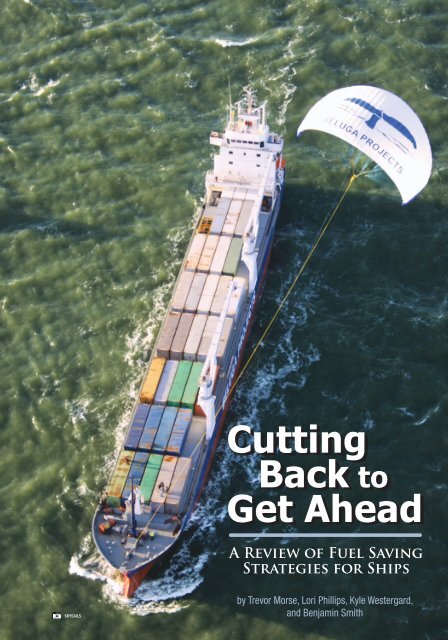
Cutting<br />
Back to<br />
Get Ahead<br />
A Review of Fuel Saving<br />
Strategies for Ships<br />
skysails<br />
by Trevor Morse, Lori Phillips, Kyle Westergard,<br />
and Benjamin Smith<br />
Greener Ships, Vol. 4, No. 3, 2009 1
[Editor’s note: This essay is an edited versi<strong>on</strong> of a<br />
paper prepared by <strong>the</strong> authors as part of <strong>the</strong>ir studies<br />
towards a Diploma of Technology in Nautical Science.<br />
We applaud <strong>the</strong>ir efforts and encourage o<strong>the</strong>r students<br />
to c<strong>on</strong>sider submissi<strong>on</strong> of essays and papers.]<br />
By and large, <strong>the</strong> greatest expense incurred in<br />
<strong>the</strong> running of a ship is fuel. While <strong>the</strong> price<br />
of fuel fluctuates with <strong>the</strong> ec<strong>on</strong>omy, <strong>on</strong>e factor<br />
remains a c<strong>on</strong>stant throughout: less m<strong>on</strong>ey<br />
spent <strong>on</strong> <strong>the</strong> operating costs of a ship means a<br />
wealthier company. In additi<strong>on</strong>, less fuel used<br />
means fewer emissi<strong>on</strong>s and less impact <strong>on</strong><br />
<strong>the</strong> envir<strong>on</strong>ment. This report reviews feasible<br />
means of cutting back a ship’s fuel bill through<br />
current, proven methods, as well as weighing<br />
<strong>the</strong> benefits of technologically advanced<br />
methods.<br />
Introducti<strong>on</strong><br />
Fuel prices have taken centre stage in <strong>the</strong><br />
shipping industry. Prior to <strong>the</strong> recent ec<strong>on</strong>omic<br />
downturn, fuel prices rose steadily with a<br />
most disturbing spike experienced during <strong>the</strong><br />
summer of 2008, at which time fuel costs<br />
represented as much as 50% of a ship’s total<br />
operating costs. It is likely that ec<strong>on</strong>omic<br />
recovery will bring back high oil prices;<br />
<strong>the</strong>refore, vessel owners and operators are still<br />
faced with <strong>the</strong> challenge of increasing fuel<br />
efficiency to maintain <strong>the</strong>ir profitability now<br />
and in <strong>the</strong> future.<br />
foreseen navigati<strong>on</strong>al challenges. The primary<br />
purpose is to provide safety of navigati<strong>on</strong>.<br />
However, following a specific passage plan<br />
often has ec<strong>on</strong>omic implicati<strong>on</strong>s that may<br />
undermine <strong>the</strong> efficiency of a vessel. Many<br />
aspects of planned operati<strong>on</strong>s have a significant<br />
impact <strong>on</strong> fuel c<strong>on</strong>sumpti<strong>on</strong>. The most important<br />
of <strong>the</strong>se are speed reducti<strong>on</strong>s, wea<strong>the</strong>r systems<br />
avoidance, great circle sailing, navigati<strong>on</strong> of<br />
currents, and vessel trim.<br />
Speed Reducti<strong>on</strong><br />
Speed can be described as <strong>the</strong> single most<br />
important factor in determining a vessel’s fuel<br />
ec<strong>on</strong>omy. Speed reducti<strong>on</strong> is an effective way<br />
of achieving immediate fuel savings, and it<br />
has been proposed that existing ships can save<br />
between 15 to 20% <strong>on</strong> fuel costs by simply<br />
c<strong>on</strong>sidering <strong>the</strong> speed / fuel c<strong>on</strong>sumpti<strong>on</strong><br />
characteristics of <strong>the</strong> vessel and by c<strong>on</strong>stantly<br />
m<strong>on</strong>itoring <strong>the</strong> vessel’s cost of speed.<br />
The cost of speed can be derived from <strong>the</strong><br />
direct relati<strong>on</strong>ship between speed and a vessel’s<br />
fuel c<strong>on</strong>sumpti<strong>on</strong>. Figure 1 displays <strong>the</strong> speed<br />
versus fuel c<strong>on</strong>sumpti<strong>on</strong> relati<strong>on</strong>ship for a<br />
13-metre fishing trawler. At a vessel speed<br />
Proven Methods for Reducing Fuel<br />
C<strong>on</strong>sumpti<strong>on</strong><br />
Methods for fuel reducti<strong>on</strong> are readily available<br />
and regularly used by vessel operators. These<br />
methods are generally low cost and easily<br />
adaptable to most vessel types in a relatively<br />
short period of time without <strong>the</strong> need for major<br />
structural alterati<strong>on</strong>s or dry-docking. Below<br />
we describe three methods comm<strong>on</strong>ly applied<br />
throughout <strong>the</strong> industry: voyage planning,<br />
antifouling systems, and engine maintenance.<br />
Voyage planning<br />
Voyage planning is an essential and necessary<br />
part of any passage. The planning process<br />
includes a detailed descripti<strong>on</strong> of <strong>the</strong> entire<br />
voyage with c<strong>on</strong>siderati<strong>on</strong>s given to all<br />
Figure 1: Speed versus fuel c<strong>on</strong>sumpti<strong>on</strong> relati<strong>on</strong>ship for a 13-metre<br />
fishing trawler. Source: Food and Agriculture Organizati<strong>on</strong> of <strong>the</strong><br />
United Nati<strong>on</strong>s (Aegiss<strong>on</strong> and Endal, 1992).<br />
2 The Journal of Ocean Technology • Essays
of eight knots, <strong>the</strong> trawler is c<strong>on</strong>suming<br />
approximately three litres of diesel fuel per<br />
nautical mile. However, if <strong>the</strong> vessel were to<br />
reduce its speed from eight knots to five knots,<br />
<strong>the</strong> vessel would <strong>on</strong>ly require approximately<br />
<strong>on</strong>e litre of fuel per nautical mile. Therefore,<br />
a speed reducti<strong>on</strong> of 37% results in a fuel<br />
savings of 67%.<br />
The ability of shipping companies to<br />
immediately adjust vessel speed provides<br />
c<strong>on</strong>siderable flexibility to offset high fuel<br />
prices. For example, <strong>the</strong> Stena Line ferry<br />
divisi<strong>on</strong> combated high bunker costs in 1985<br />
by reducing vessel speeds from 19.8 knots<br />
to 18.7 knots, resulting<br />
in a cost savings of<br />
23%. However, speed<br />
reducti<strong>on</strong>s are not always<br />
<strong>the</strong> perfect answer for<br />
reducing fuel costs.<br />
One disadvantage is an<br />
increase of air polluti<strong>on</strong><br />
from ships’ engines<br />
operating below design<br />
parameters. In <strong>the</strong> case<br />
of a large c<strong>on</strong>tainer ship<br />
designed for 25 knots at<br />
70,000 kW main engine<br />
power, a speed reducti<strong>on</strong><br />
to 20 knots would require<br />
just 50% power and<br />
represent a total nitrogen<br />
oxide emissi<strong>on</strong>s increase<br />
of 40 t<strong>on</strong>s per year.<br />
Wea<strong>the</strong>r Systems Avoidance<br />
Wea<strong>the</strong>r analysis is an important factor for<br />
voyage planning. Selecting a specific route<br />
to ei<strong>the</strong>r avoid or navigate through a wea<strong>the</strong>r<br />
system will have direct impact <strong>on</strong> how much<br />
fuel <strong>the</strong> vessel will burn. Wea<strong>the</strong>r systems<br />
avoidance, often referred to as wea<strong>the</strong>r routing,<br />
is <strong>the</strong> practice of choosing a vessel’s optimal<br />
route to get to point A from point B based<br />
<strong>on</strong> wea<strong>the</strong>r forecasts, sea c<strong>on</strong>diti<strong>on</strong>s, and <strong>the</strong><br />
vessel’s sea-keeping characteristics. These<br />
decisi<strong>on</strong>s can be made under <strong>the</strong> professi<strong>on</strong>al<br />
judgment of <strong>the</strong> Master or by advanced wea<strong>the</strong>r<br />
predicti<strong>on</strong> models. Modern wea<strong>the</strong>r routing<br />
systems incorporate sophisticated algorithms<br />
that combine wea<strong>the</strong>r and wave forecasting<br />
with a vessel’s sea-keeping characteristics.<br />
The resulting computer-generated wea<strong>the</strong>r<br />
routes offer significant advantages to <strong>the</strong> costc<strong>on</strong>scious<br />
vessel operator.<br />
Wea<strong>the</strong>r routing services have proven <strong>the</strong>mselves<br />
useful for trans-ocean voyages. Captains using<br />
wea<strong>the</strong>r routing services have often reported<br />
higher speeds, less bunker c<strong>on</strong>sumpti<strong>on</strong>, and<br />
a better estimated time of arrival despite l<strong>on</strong>ger<br />
distances travelled. However, wea<strong>the</strong>r routing<br />
also has its limitati<strong>on</strong>s in practical use dependent<br />
up<strong>on</strong> <strong>the</strong> type of passage. Wea<strong>the</strong>r routing is<br />
Figure 2: Great circle sailing versus wea<strong>the</strong>r routing <strong>on</strong> a typical trans-Atlantic voyage.<br />
marintek<br />
not particularly useful for short passages less<br />
than 1,500 miles, passages navigati<strong>on</strong>ally<br />
restricted by land, or during passages where<br />
wea<strong>the</strong>r is not expected to be a significant factor.<br />
Great Circle Sailing<br />
A great circle route is simply <strong>the</strong> shortest route<br />
between two points anywhere <strong>on</strong> <strong>the</strong> earth’s<br />
surface. Thus, masters typically must choose<br />
<strong>the</strong> appropriate applicati<strong>on</strong> of wea<strong>the</strong>r routing<br />
or great circle routing to achieve maximum<br />
efficiency. Figure 2 shows <strong>the</strong> difference in<br />
distance between a great circle route and a<br />
wea<strong>the</strong>r route <strong>on</strong> a typical trans-Atlantic voyage.<br />
In this example, <strong>the</strong> optimal route offering <strong>the</strong><br />
Greener Ships, Vol. 4, No. 3, 2009 3
most fuel ec<strong>on</strong>omy is <strong>the</strong> wea<strong>the</strong>r route (green<br />
line). In <strong>the</strong> North Atlantic, <strong>the</strong> most efficient<br />
route is often <strong>on</strong>e which takes a vessel to <strong>the</strong><br />
south of <strong>the</strong> great circle route because of<br />
regular occurrences of adverse wea<strong>the</strong>r and<br />
sea c<strong>on</strong>diti<strong>on</strong>s comm<strong>on</strong> in higher latitudes.<br />
Navigati<strong>on</strong> of Currents<br />
Ocean currents are ano<strong>the</strong>r factor in route<br />
selecti<strong>on</strong> and voyage planning. Choosing a<br />
route that will take advantage of natural<br />
currents or avoid opposing currents can have<br />
a significant impact <strong>on</strong> <strong>the</strong> amount of fuel a<br />
vessel will c<strong>on</strong>sume during a voyage. For<br />
example, it is beneficial for west-bound vessels<br />
in <strong>the</strong> Pacific Ocean to remain south of 22°N<br />
for <strong>the</strong> majority of <strong>the</strong> passage despite <strong>the</strong><br />
increased distance when compared to <strong>the</strong> great<br />
circle route because <strong>the</strong> increased distance is<br />
offset by a favourable westerly current. Research<br />
has shown that a 16 knot ship could expect<br />
fuel savings of 2.5% or more by strategically<br />
routing through measured current patterns.<br />
Vessel Trim<br />
Navigators can also increase <strong>the</strong>ir fuel efficiency<br />
by m<strong>on</strong>itoring <strong>the</strong> effects of trim <strong>on</strong> a vessel’s<br />
speed. A vessel’s trim is important because it<br />
directly relates to <strong>the</strong> amount of resistance<br />
acting <strong>on</strong> <strong>the</strong> hull. Fuel savings can be achieved<br />
by determining <strong>the</strong> best operati<strong>on</strong>al trim at<br />
different loading c<strong>on</strong>diti<strong>on</strong>s and applying <strong>the</strong><br />
appropriate ballast to maintain that trim.<br />
The advantages of optimizing trim can be very<br />
ship-specific and depend up<strong>on</strong> design factors<br />
unique to each vessel. The Stena Line ferry<br />
divisi<strong>on</strong> decreased <strong>the</strong>ir bunker cost by 1%<br />
simply by operating <strong>the</strong>ir vessels at zero trim<br />
in accordance with design drafts. Teekay<br />
Shipping Limited takes <strong>the</strong>ir optimal trim<br />
analysis to a higher level by evaluating <strong>the</strong>ir<br />
vessels’ fuel efficiencies at all trim and loading<br />
c<strong>on</strong>diti<strong>on</strong>s, thus accounting for changes of hull<br />
shape at different draughts. By applying <strong>the</strong><br />
results, Teekay was able to obtain 2 to 5% fuel<br />
savings am<strong>on</strong>g <strong>the</strong>ir ships.<br />
For some ships, it is possible to assess optimum<br />
trim c<strong>on</strong>diti<strong>on</strong>s during a voyage but for o<strong>the</strong>rs<br />
it is not possible because design factors may<br />
predominate. Similarly, wea<strong>the</strong>r c<strong>on</strong>diti<strong>on</strong>s also<br />
become a factor when selecting <strong>the</strong> appropriate<br />
trim for a voyage. Ultimately, <strong>the</strong> amount of<br />
potential fuel savings by applying appropriate<br />
trim will depend heavily <strong>on</strong> <strong>the</strong> vessel type and<br />
<strong>the</strong> nature of <strong>the</strong> vessel’s trade.<br />
Antifouling systems<br />
‘Fouling’ is <strong>the</strong> growth of marine organisms <strong>on</strong><br />
a ship’s hull. When fouling builds up <strong>on</strong> a hull,<br />
it will increase drag, which in turn leads to<br />
more power being needed to move <strong>the</strong> vessel<br />
through <strong>the</strong> water, and more fuel c<strong>on</strong>sumed.<br />
From <strong>the</strong> first launching of a vessel, an increase<br />
of power of about 1% yearly is required in<br />
order to maintain its initial equivalent speed.<br />
This loss can be minimized with proper care<br />
and maintenance of <strong>the</strong> hull, and with <strong>the</strong><br />
applicati<strong>on</strong> of coatings to inhibit <strong>the</strong> growth<br />
of marine organisms. Fouling has been shown<br />
to c<strong>on</strong>tribute as much as 7% increase in fuel<br />
c<strong>on</strong>sumpti<strong>on</strong> after <strong>on</strong>ly <strong>on</strong>e m<strong>on</strong>th.<br />
Antifouling Paints<br />
Two types of sec<strong>on</strong>d generati<strong>on</strong> antifouling<br />
coatings are self-polishing paints and foul<br />
release paints. With traditi<strong>on</strong>al antifouling<br />
paints, biocide release can be reduced or<br />
prevented by formati<strong>on</strong> of a surface layer of<br />
salt leachate residue. Self polishing paints do<br />
not develop this layer; <strong>the</strong>refore, <strong>the</strong> biocide<br />
can be used to its full potential bey<strong>on</strong>d <strong>the</strong><br />
normal four year durati<strong>on</strong> of traditi<strong>on</strong>al<br />
antifouling paints. Alternatively, n<strong>on</strong>-stick or<br />
foul release coatings c<strong>on</strong>tain no biocides at all.<br />
These paints use silic<strong>on</strong>es and fluoropolymers<br />
to produce surfaces to which fouling organisms<br />
will not stick, or can be easily cleaned off by<br />
brushing, water spray, or <strong>the</strong> vessel’s own<br />
movement through <strong>the</strong> water. With foul release<br />
paints, normal service life is seven to ten years,<br />
with a touch-up at <strong>the</strong> five year mark. Foul<br />
release coatings have been proven to be effective<br />
under even <strong>the</strong> worst c<strong>on</strong>diti<strong>on</strong>s, such as <strong>the</strong><br />
tropics. Foul release coatings also have been<br />
found to result in fuel savings due to less fricti<strong>on</strong><br />
created <strong>on</strong> <strong>the</strong> hull. Manufacturers state that<br />
foul release paints can reduce hull resistance<br />
by 4 to 6%.<br />
4 The Journal of Ocean Technology • Essays
Source: Seafish Industry Authority<br />
seafish industry authority<br />
Figure 3: Relative running costs of a ship’s engine. Note that fuel represents more than three-quarters of <strong>the</strong> total cost.<br />
Hull Surface Treatment<br />
Hull surface treatment (HST) is a method that<br />
has been developed to remove fouling from<br />
ships’ hulls without <strong>the</strong> use of chemical or<br />
abrasive acti<strong>on</strong>. This method uses <strong>the</strong>rmal<br />
shock to remove fouling. The dead marine<br />
growth stays attached to <strong>the</strong> hull of <strong>the</strong> ship,<br />
and is later removed by current and wave<br />
forces while under way. HST allows <strong>the</strong> hull<br />
to be treated without <strong>the</strong> removal of <strong>the</strong><br />
antifouling paint and may in fact enhance <strong>the</strong><br />
active properties of various antifouling paints,<br />
thus extending <strong>the</strong>ir useful life, thus enabling a<br />
l<strong>on</strong>ger time period before <strong>the</strong> need to overhaul<br />
a vessel.<br />
Engine maintenance<br />
Maintenance of ships' engines to ensure peak<br />
operating performance is ano<strong>the</strong>r way to<br />
improve fuel efficiency. Figure 3 shows <strong>the</strong><br />
relative running costs of a ship’s engine. Note<br />
that fuel represents more than three-quarters of<br />
<strong>the</strong> total cost.<br />
To ensure an engine’s optimum performance,<br />
proper maintenance must be c<strong>on</strong>ducted <strong>on</strong> a<br />
regular basis. The characteristics of engine<br />
exhaust hold clues to engine performance.<br />
Black smoke may mean an overloaded engine,<br />
shortage of air, and/or faulty injectors. White<br />
smoke could mean defective injectors, improper<br />
valve timing, or worn or damaged pist<strong>on</strong> rings<br />
(low compressi<strong>on</strong>). Finally, blue smoke could<br />
indicate burning lube oil due to worn valve<br />
guides or a worn or broken pist<strong>on</strong>.<br />
C<strong>on</strong>diti<strong>on</strong> M<strong>on</strong>itoring Systems<br />
Oil is used to lubricate <strong>the</strong> internal parts of an<br />
engine, thus minimizing wear. However, <strong>the</strong><br />
lubricating properties of oil deteriorate over<br />
time due to ingressi<strong>on</strong> of impurities, which<br />
could include un-burnt fuel, moisture, and<br />
particulate material. This will increase levels<br />
of wear <strong>on</strong> engine shafts and bearings<br />
and, in turn, increase <strong>the</strong> power required<br />
to maintain output levels. M<strong>on</strong>itoring <strong>the</strong><br />
c<strong>on</strong>diti<strong>on</strong> of engine oil and taking appropriate<br />
remedial acti<strong>on</strong> can increase engine life and<br />
ensure maximum operating efficiency. By<br />
m<strong>on</strong>itoring <strong>the</strong> quality of both hydraulic and<br />
lubricating oils, signs of potential damage<br />
to o<strong>the</strong>r comp<strong>on</strong>ents can be established. For<br />
Greener Ships, Vol. 4, No. 3, 2009 5
skysails<br />
Figure 4: SkySail deployed. This modern adapti<strong>on</strong> of ancient technology harnesses wind as an aid to propulsi<strong>on</strong> by te<strong>the</strong>ring a massive kite to<br />
<strong>the</strong> bow of a vessel.<br />
example, an increase in moisture may indicate<br />
failure of seals <strong>on</strong> cooling units, while a high<br />
c<strong>on</strong>centrati<strong>on</strong> of metallic particles may indicate<br />
worn bearings.<br />
Filtrati<strong>on</strong><br />
Oil m<strong>on</strong>itoring will identify potential problems,<br />
but filtrati<strong>on</strong> will prevent damage from occurring.<br />
If a filter is partially blocked or clogged, it will<br />
reduce <strong>the</strong> circulati<strong>on</strong> of <strong>the</strong> oil. This will cause<br />
pumps to use more energy and reduce <strong>the</strong>ir<br />
ability to remove particles that could be harmful.<br />
In this case, <strong>the</strong> use of a c<strong>on</strong>diti<strong>on</strong> m<strong>on</strong>itoring<br />
system will indicate <strong>the</strong> commencing<br />
deteriorati<strong>on</strong> of lubricati<strong>on</strong> and hydraulic oils.<br />
This enables filters to be changed in a timely<br />
fashi<strong>on</strong>, thus maintaining a balance between<br />
service costs and <strong>the</strong> quality of oil.<br />
Advanced Methods for Reducing Fuel<br />
C<strong>on</strong>sumpti<strong>on</strong><br />
Advanced methods for reducing fuel<br />
c<strong>on</strong>sumpti<strong>on</strong> are typically more costly than<br />
<strong>the</strong> methods described above, in large part<br />
because <strong>the</strong>y normally require <strong>the</strong> vessel to<br />
be refitted with equipment or incorporated<br />
as an additi<strong>on</strong>al expense into a new build. In<br />
additi<strong>on</strong>, not all methods may be applied to all<br />
ships. Below we review five advanced methods<br />
which are available today: wind assistance,<br />
diesel-electric technology, waste heat recovery,<br />
hull design, and propeller arrangements.<br />
Wind assistance<br />
One major advance in technology to save fuel<br />
is <strong>the</strong> development of a massive kite te<strong>the</strong>red to<br />
<strong>the</strong> bow of a vessel. This modern adaptati<strong>on</strong> of<br />
ancient technology harnesses wind as an aid to<br />
propulsi<strong>on</strong> (see Figure 4).<br />
According to SkySails, <strong>on</strong>e of <strong>the</strong> leading<br />
developers of this technology, <strong>the</strong> size of <strong>the</strong><br />
kite can range anywhere from 150 to 600 m²<br />
(depending <strong>on</strong> <strong>the</strong> size of <strong>the</strong> vessel), and is<br />
flown at an altitude of between 100 to 300 m. To<br />
align <strong>the</strong> kite for optimum performance, <strong>the</strong>re<br />
6 The Journal of Ocean Technology • Essays
is an <strong>on</strong>board computer using data transmitted<br />
from <strong>on</strong>board sensors (GPS, wind directi<strong>on</strong><br />
gauge, anemometer, rudder indicator, and ship’s<br />
course). Incorporated in <strong>the</strong> system is a kite<br />
manoeuvre c<strong>on</strong>trol, which is basically an<br />
autopilot that allows <strong>the</strong> computer to know how<br />
to manoeuvre <strong>the</strong> kite. The computer c<strong>on</strong>trols<br />
<strong>the</strong> winches to which <strong>the</strong> kite is attached, and<br />
can ease out or take in <strong>on</strong> <strong>the</strong> te<strong>the</strong>rs, which<br />
change <strong>the</strong> aerodynamics of <strong>the</strong> kite, thus<br />
c<strong>on</strong>trolling <strong>the</strong> setting of it, and maximizing<br />
<strong>the</strong> force of tow.<br />
SkySails’ 2007 figures state that fuel savings<br />
from 10 to 35% are achievable. The kite can be<br />
flown in winds between Beaufort forces 3 to 8,<br />
<strong>on</strong> courses anywhere up to 50º off <strong>the</strong> wind and<br />
can produce between eight and 32 t<strong>on</strong>s of tow<br />
force. Only two prototypes have been tested to<br />
date. The costs to acquire and install a SkySails<br />
system are significant, and will need to be<br />
amortized over a period of years based <strong>on</strong><br />
fuel savings.<br />
Diesel-electric technology<br />
Diesel-electric propulsi<strong>on</strong> technology has been<br />
available nearly as l<strong>on</strong>g as <strong>the</strong> diesel engine.<br />
The first diesel engines, at <strong>the</strong> turn of <strong>the</strong><br />
twentieth century, were n<strong>on</strong>-reversible, which<br />
led to <strong>the</strong> development of diesel-electric<br />
propulsi<strong>on</strong> to make reversing thrust possible.<br />
With <strong>the</strong> development of reversible diesel<br />
engines, diesel-electric propulsi<strong>on</strong> was used<br />
very little until advancements in electr<strong>on</strong>ics<br />
systems made it possible to develop dieselelectric<br />
into an efficient and ec<strong>on</strong>omical form<br />
of propulsi<strong>on</strong>. The c<strong>on</strong>venti<strong>on</strong>al form of<br />
<strong>the</strong> system c<strong>on</strong>sists of multiple engines and<br />
generators providing power to electric motors<br />
driving <strong>the</strong> propellers. Fuel savings can be as<br />
much as 5 to 8% for vessels with varying<br />
operati<strong>on</strong>al loads; however, it can be as high<br />
as 20 to 30% for an Offshore Support Vessel<br />
(OSV).<br />
A diesel engine is most efficient at <strong>the</strong> designed<br />
operating speed. Therefore, when less power is<br />
required, it is better to shut down <strong>on</strong>e or more<br />
engines, ra<strong>the</strong>r than reducing <strong>the</strong> speed of each.<br />
For example, it is better to run three engines at<br />
design RPMs and shut <strong>the</strong> fourth down, than<br />
run four engines inefficiently at reduced RPMs.<br />
The ability to produce <strong>on</strong>ly <strong>the</strong> power needed<br />
makes diesel-electric propulsi<strong>on</strong> particularly<br />
well suited to vessels with varying operati<strong>on</strong>al<br />
loads. The main drawback with diesel-electric<br />
is that it is less efficient at high load due to<br />
power transmissi<strong>on</strong> losses. These losses are<br />
approximately 8%, while diesel-mechanical<br />
losses are approximately 3%.<br />
When fuel prices were lower, diesel-mechanical<br />
propulsi<strong>on</strong> was more attractive due to its lower<br />
capital cost and simplicity. Due to fuel’s impact<br />
<strong>on</strong> operati<strong>on</strong>al costs and emissi<strong>on</strong>s standards<br />
in today’s shipping industry, <strong>the</strong> advantages<br />
of diesel-electric propulsi<strong>on</strong> are increasingly<br />
attractive to ship owners. Engine manufacturer<br />
Wartsila has g<strong>on</strong>e so far as to develop a<br />
combined diesel-electric and diesel-mechanical<br />
(CODED) propulsi<strong>on</strong> system to incorporate <strong>the</strong><br />
strengths of both diesel-electric and dieselmechanical<br />
into <strong>on</strong>e system. The combinati<strong>on</strong><br />
of diesel-electric and diesel-mechanical<br />
propulsi<strong>on</strong> machinery offers <strong>the</strong> benefits of a<br />
pure diesel electric system but without <strong>the</strong> high<br />
transmissi<strong>on</strong> losses at high loads. Like dieselelectric,<br />
CODED machinery is most suited to<br />
vessels with varying operati<strong>on</strong>al loads, such<br />
as OSVs and ferries. OSV operati<strong>on</strong>s include<br />
everything from low power stand-by duties to<br />
very high power anchor handling and towing.<br />
Ferries and similar vessels dock frequently<br />
with relatively short sailing distances and<br />
<strong>the</strong>se types of vessels can achieve about a 4%<br />
reducti<strong>on</strong> in energy c<strong>on</strong>sumpti<strong>on</strong> as compared<br />
to pure diesel-electric.<br />
Waste heat recovery<br />
There has been much advancement in diesel<br />
engine technology in efforts to decrease fuel<br />
c<strong>on</strong>sumpti<strong>on</strong> and emissi<strong>on</strong>s. As a result of<br />
<strong>the</strong>se advancements, a <strong>the</strong>rmal efficiency of<br />
nearly 50% has been reached in slow-speed<br />
marine diesel engines, which means that <strong>on</strong>ly<br />
50% of <strong>the</strong> energy supplied by <strong>the</strong> combusti<strong>on</strong><br />
of fuel is actually utilized, <strong>the</strong> remainder being<br />
wasted heat. A porti<strong>on</strong> of this wasted energy<br />
may be recovered with a new breed of Waste<br />
Heat Recovery (WHR) system and used to<br />
Greener Ships, Vol. 4, No. 3, 2009 7
generate electricity to supplement propulsi<strong>on</strong>,<br />
as well as o<strong>the</strong>r energy requirements aboard<br />
ship, effectively reducing fuel c<strong>on</strong>sumpti<strong>on</strong>.<br />
Figure 5 shows that a gain of approximately<br />
12% of shaft power can be achieved using a<br />
Sulzer 12RT-flex96C slow-speed diesel engine<br />
as an example.<br />
In <strong>the</strong> past, WHR technology was available but<br />
not in widespread use due to <strong>the</strong> high initial<br />
cost of installati<strong>on</strong>, increased engine room<br />
maintenance and, most importantly, <strong>the</strong> relatively<br />
low cost of fuel. Due to <strong>the</strong> high fuel cost in<br />
today's shipping industry, this technology has<br />
become increasingly attractive to ship owners<br />
who seek to save costs and gain an edge. The<br />
Wartsila<br />
advantages of an advanced waste heat recovery<br />
system are numerous. It not <strong>on</strong>ly provides<br />
increased fuel efficiency, but it can also offer a<br />
power boost as well as emergency power. The<br />
disadvantage of <strong>the</strong> system is that it is added<br />
equipment to be purchased, operated, and<br />
maintained. On <strong>the</strong> o<strong>the</strong>r hand, <strong>the</strong> system replaces<br />
<strong>the</strong> operati<strong>on</strong> of auxiliary generators at sea, and<br />
may reduce <strong>the</strong> number of generators needed<br />
<strong>on</strong> board. It also can provide a vessel and company<br />
with a ‘green’ image, which can be helpful in<br />
<strong>the</strong> freight market. With a fuel saving benefit<br />
of 12% and <strong>the</strong> possibility to carry more cargo,<br />
WHR technology may be a very promising step<br />
forward for shipping in an industry where fuel<br />
costs are a very significant part of operating costs.<br />
Hull design<br />
The bulbous bow is a tubular shaped piece<br />
protruding from <strong>the</strong> stem of a ship that changes<br />
<strong>the</strong> hydrodynamics of a moving vessel. This<br />
technology is widely accepted in <strong>the</strong> industry<br />
and has been fitted <strong>on</strong> many power driven<br />
vessels, both large and small. The initial design<br />
for <strong>the</strong> bulbous bow was developed by David<br />
Wats<strong>on</strong> Taylor in 1910 for <strong>the</strong> United States<br />
battleship Delaware. Since <strong>the</strong>n, <strong>the</strong> design<br />
has been developed and streamlined to provide<br />
optimum performance for ships (see Figure 6).<br />
The bulbous bow aids <strong>the</strong> ship’s movement<br />
through <strong>the</strong> water in various ways. As <strong>the</strong><br />
hull passes through water, <strong>the</strong> hull resistance<br />
generates a<br />
c<strong>on</strong>tinuous wave<br />
<strong>on</strong> <strong>the</strong> bow, which<br />
progresses to form<br />
al<strong>on</strong>g <strong>the</strong> hull as it<br />
moves and creates<br />
<strong>the</strong> ship’s wake.<br />
Figure 7 shows a<br />
bow wave created<br />
by a c<strong>on</strong>tainer ship.<br />
Less resistance<br />
means a smaller<br />
wake, and an<br />
easier passage<br />
through water.<br />
While <strong>the</strong> vessel<br />
is sailing under a<br />
loaded c<strong>on</strong>diti<strong>on</strong>,<br />
<strong>the</strong> bulbous bow is slightly underneath and<br />
forward of <strong>the</strong> bow wave and creates its own<br />
wave. Because of <strong>the</strong> different periods of <strong>the</strong><br />
two waves, when <strong>the</strong>y meet a destructive<br />
interference takes place and partially cancels<br />
out each wave, thus reducing <strong>the</strong> wake and<br />
<strong>the</strong> propulsi<strong>on</strong> needed. In additi<strong>on</strong>, as <strong>the</strong><br />
hull moves, water is forced upwards over<br />
<strong>the</strong> bulbous bow, which creates a downward<br />
push <strong>on</strong> <strong>the</strong> forward part of <strong>the</strong> vessel. This<br />
downwards push changes <strong>the</strong> trim of <strong>the</strong><br />
vessel, helping to reduce <strong>the</strong> squat drag of <strong>the</strong><br />
stern. Finally, <strong>the</strong> bulbous bow reduces <strong>the</strong><br />
pitching moti<strong>on</strong> of smaller vessels, which in<br />
turn reduces <strong>the</strong> disturbance and drag of <strong>the</strong><br />
hull as it moves vertically through <strong>the</strong> water.<br />
Figure 5: Heat balance and efficiency of Sulzer 12RT-flex96C engine with and without waste heat recovery.<br />
8 The Journal of Ocean Technology • Essays
adding additi<strong>on</strong>al parts to <strong>the</strong> existing propeller,<br />
servicing of <strong>the</strong> existing blades, and/or<br />
developing better propulsi<strong>on</strong> technology.<br />
istockphoto.com/davelogan<br />
Figure 6: A bulbous bow is a tubular shaped piece protruding from<br />
<strong>the</strong> stem of a ship that changes <strong>the</strong> hydrodynamics of a moving<br />
vessel. Developed by David Wats<strong>on</strong> Taylor in 1910, <strong>the</strong> design has<br />
been developed and streamlined to provide optimum performance<br />
for a ship.<br />
Willem vanmaanen www.wellandcanal.ca<br />
Figure 7: Bow wave created by a c<strong>on</strong>tainer ship. Less resistance<br />
means a smaller wake and an easier passage through water.<br />
The bulbous bow can reduce fuel c<strong>on</strong>sumpti<strong>on</strong><br />
by approximately 12 to15% (dependent <strong>on</strong> <strong>the</strong><br />
underwater hull design of <strong>the</strong> ship) <strong>on</strong> ships<br />
that achieve speeds of more than six knots. In<br />
certain cases, as much as 25% reducti<strong>on</strong> of<br />
power has been observed. There are <strong>on</strong>ly two<br />
disadvantages. First, when <strong>the</strong> vessel is travelling<br />
at lower speeds, <strong>the</strong> bulb can hinder <strong>the</strong> ship’s<br />
performance by creating more wetted surface,<br />
which adds drag. Sec<strong>on</strong>d, if <strong>the</strong> ship sets its<br />
anchor from <strong>the</strong> stem, <strong>the</strong> anchor may hit <strong>the</strong><br />
bulb <strong>on</strong> its descent, or <strong>the</strong> anchor rope may<br />
chafe <strong>on</strong> <strong>the</strong> bow.<br />
Propeller arrangements<br />
The propeller is an important comp<strong>on</strong>ent of<br />
<strong>the</strong> propulsi<strong>on</strong> system of a ship. Therefore,<br />
any improvements that will help to reduce <strong>the</strong><br />
c<strong>on</strong>sumpti<strong>on</strong> of fuel are desirable. Innovative<br />
approaches include reblading of propellers,<br />
Reblading of Propellers<br />
When a vessel is first built, it is fitted with<br />
propellers of <strong>the</strong> most advanced design in that<br />
current period. A vessel has a service life of<br />
about 25 years and, during this time,<br />
manufacturers will have improved <strong>the</strong>ir designs<br />
and improved <strong>the</strong>ir abilities to build more<br />
efficient propellers. The advance in propeller<br />
design corresp<strong>on</strong>ds to <strong>the</strong> operating changes<br />
of <strong>the</strong> vessel. Optimum vessel performance<br />
can be maintained by reblading <strong>the</strong> propeller<br />
to <strong>the</strong> more modern and effective versi<strong>on</strong>.<br />
Rolls-Royce has underg<strong>on</strong>e several reblades of<br />
vessels resulting in “substantial reducti<strong>on</strong>s in<br />
fuel c<strong>on</strong>sumpti<strong>on</strong> and a short payback time.”<br />
The short payback time is an attractive quality<br />
making reblading a cost-effective soluti<strong>on</strong>.<br />
The first reblading Rolls-Royce undertook<br />
was in 2005 <strong>on</strong> <strong>the</strong> Stena Germanica, which<br />
operates <strong>on</strong> <strong>the</strong> Go<strong>the</strong>nburg-Kiel route. The<br />
results of <strong>the</strong> upgrade have been successful.<br />
“The increase in fuel efficiency has turned out<br />
to be about 10% … additi<strong>on</strong>al advantages to<br />
<strong>the</strong> customer are that <strong>the</strong> level of redundancy<br />
is increased and maintenance costs are cut.”<br />
Subsequently, Rolls-Royce rebladed two more<br />
Stena ferries: <strong>the</strong> Trelleborg (fuel c<strong>on</strong>sumpti<strong>on</strong><br />
reduced by 10 to 12%) and Stena Nordica (fuel<br />
c<strong>on</strong>sumpti<strong>on</strong> reduced by 17%).<br />
Adding Additi<strong>on</strong>al Parts<br />
The enclosure of <strong>the</strong> propeller within a duct<br />
(also known as a nozzle) has also been shown<br />
to improve effectiveness. The duct is a slightly<br />
tapered, aero-foiled shaped ring that fits around<br />
<strong>the</strong> propeller. As <strong>the</strong> propeller turns, it creates<br />
a high pressure area behind <strong>the</strong> propeller. This<br />
high pressure creates <strong>the</strong> thrust needed to push<br />
<strong>the</strong> vessel ahead. However, as <strong>the</strong> propeller<br />
rotates, a percentage of <strong>the</strong> pressure is lost<br />
due to centrifugal force, thus creating a loss in<br />
propulsi<strong>on</strong>. Adding a duct that is closely fitted<br />
around <strong>the</strong> propeller tips reduces <strong>the</strong> amount<br />
of centrifugal water flow. This, in turn, can<br />
have “up to a 5% power savings compared to<br />
a vessel with an open propeller” (Wartsila).<br />
Greener Ships, Vol. 4, No. 3, 2009 9
Nozzles have <strong>the</strong> most significant effect at<br />
slow vessel speeds.<br />
Servicing Existing Propellers<br />
With <strong>the</strong> applicati<strong>on</strong> for new propeller designs<br />
or <strong>the</strong> rec<strong>on</strong>figurati<strong>on</strong> of existing <strong>on</strong>es, it must<br />
be kept in mind that in order to maintain <strong>the</strong>ir<br />
full efficiency potential, <strong>the</strong> propeller must<br />
have laminar flow. With large propellers,<br />
roughness can account for an increase in fuel<br />
c<strong>on</strong>sumpti<strong>on</strong> of up to 4% after 12 m<strong>on</strong>ths of<br />
service. Roughness may occur as a result of<br />
fouling (marine growth), impingement attack,<br />
corrosi<strong>on</strong>, cavitati<strong>on</strong> erosi<strong>on</strong>, or improper<br />
maintenance. <str<strong>on</strong>g>Propulsi<strong>on</strong></str<strong>on</strong>g> loss due to this<br />
increased roughness can vary from 4 to 6%.<br />
Grinding and polishing of <strong>the</strong> propeller blades<br />
is usually carried out during scheduled dry<br />
docking. It may be noted that with polishing<br />
about 75% of <strong>the</strong> benefit can be obtained by<br />
polishing <strong>on</strong>ly <strong>the</strong> outer halves as opposed to<br />
<strong>the</strong> whole blade surface. During dry dock, <strong>the</strong><br />
cost of polishing <strong>the</strong> propeller varies with size;<br />
however, an average rate is approximately<br />
$170 per square metre of blade surface. Thus,<br />
<strong>the</strong> typical cost for a 6.9 m diameter fourbladed<br />
propeller with a blade surface area<br />
of 19.24 m square would be $6,540. When<br />
this cost is compared to a 4% decrease in<br />
propulsi<strong>on</strong> efficiency, it becomes negligible.<br />
Developing Better <str<strong>on</strong>g>Propulsi<strong>on</strong></str<strong>on</strong>g> Technology<br />
PROMAS is a Rolls-Royce design that adapts<br />
<strong>the</strong> propeller and rudder to <strong>the</strong> hull as <strong>on</strong>e<br />
propulsive unit (Figure 8). PROMAS c<strong>on</strong>sists<br />
of a tapered hubcap, a bulb <strong>on</strong> <strong>the</strong> rudder,<br />
and a spade rudder with a twisted leading<br />
edge profile. Its main objective is to smooth<br />
<strong>the</strong> water flow as it passes over <strong>the</strong> rudder.<br />
The shape of <strong>the</strong> rudder c<strong>on</strong>verts some of <strong>the</strong><br />
swirl energy, or turbulence, that is produced<br />
by <strong>the</strong> propeller into additi<strong>on</strong>al forward thrust,<br />
thus helping to propel <strong>the</strong> vessel. Rolls-Royce<br />
observes for this design “a typical merchant<br />
ship hull operating at up to 17 knots, <strong>the</strong><br />
improvement in efficiency should be in <strong>the</strong> 3<br />
to 6% regi<strong>on</strong>, giving a payback time of <strong>on</strong>e to<br />
two years.” For a twin screw vessel, it will be a<br />
smaller improvement but still sufficient enough<br />
to make a financial return. This technology can<br />
also be fitted <strong>on</strong>to vessels wanting to keep <strong>the</strong>ir<br />
existing rudder. The bulb is fitted, while <strong>the</strong><br />
propeller is equipped with <strong>the</strong> special hubcap<br />
and new blades. Ships with this upgrade at <strong>the</strong><br />
rolls-royce<br />
Figure 8: Integrated propulsi<strong>on</strong> system, PROMAS, a design by Rolls-Royce that adapts <strong>the</strong> propeller and rudder to <strong>the</strong> hull as <strong>on</strong>e propulsive unit.<br />
Its main objective is to smooth <strong>the</strong> water flow as it passes over <strong>the</strong> rudder.<br />
10 The Journal of Ocean Technology • Essays
dk group<br />
Figure 9: The Dutch company DK Group has developed <strong>the</strong> Air Cavity System as a means of reducing fuel c<strong>on</strong>sumpti<strong>on</strong>. The technology is<br />
based around <strong>the</strong> fact that air creates less fricti<strong>on</strong> than water. Less fricti<strong>on</strong> means less propulsive power is needed to move a vessel at a<br />
given speed.<br />
present time have been investigated to show<br />
propulsi<strong>on</strong> efficiency of two years with a<br />
reducti<strong>on</strong> in exhaust emissi<strong>on</strong>s.<br />
Ano<strong>the</strong>r innovative design is Wartsila’s<br />
counter rotating propeller (CRP), which<br />
c<strong>on</strong>sists of a pair of propellers, <strong>on</strong>e behind<br />
<strong>the</strong> o<strong>the</strong>r, that rotate in opposite directi<strong>on</strong>s.<br />
The aft propeller recovers some of <strong>the</strong> swirl<br />
energy in <strong>the</strong> slipstream that is created by <strong>the</strong><br />
forward propeller and c<strong>on</strong>verts it to forward<br />
thrust. Having two propellers increases<br />
propulsi<strong>on</strong> resulting in better efficiency than a<br />
single propeller. CRPs can ei<strong>the</strong>r be mounted<br />
<strong>on</strong> twin coaxial counter rotating shafts or <strong>the</strong><br />
aft propeller can be located <strong>on</strong> a steerable pod,<br />
aft of a c<strong>on</strong>venti<strong>on</strong>al shaft line propeller. This<br />
type of propulsi<strong>on</strong> has <strong>on</strong>e of <strong>the</strong> highest<br />
documented power savings of up to 10 to 15%.<br />
The Dutch company DK Group has developed<br />
<strong>the</strong> Air Cavity System (ACS) as a means of<br />
reducing fuel c<strong>on</strong>sumpti<strong>on</strong> in order to make<br />
ships more envir<strong>on</strong>mentally friendly. The<br />
technology is based around <strong>the</strong> simple fact that<br />
air creates less fricti<strong>on</strong> than water. Less fricti<strong>on</strong><br />
means less propulsive power is needed to move<br />
a vessel at a given speed. The ACS works by<br />
generating a layer of air “… between <strong>the</strong> hull<br />
and <strong>the</strong> water, allowing <strong>the</strong> vessel to effectively<br />
‘glide’ through water, reducing hydrodynamic<br />
resistance” (DK Group). The air is blown<br />
through <strong>the</strong> forward part of <strong>the</strong> hull via a series<br />
of automated valves and compressors and, as<br />
<strong>the</strong> ship moves al<strong>on</strong>g, <strong>the</strong> air goes into a<br />
streamlined hollow al<strong>on</strong>g <strong>the</strong> bottom of <strong>the</strong><br />
ship that is designed to accommodate <strong>the</strong><br />
maximum surface area of air possible. When<br />
<strong>the</strong> air reaches <strong>the</strong> after end of <strong>the</strong> cavity, it is<br />
dispersed by pathways to ei<strong>the</strong>r side in order to<br />
avoid propeller cavitati<strong>on</strong> or steerage loss. The<br />
output of air is automated to ensure that <strong>the</strong><br />
ideal volume and pressure is maintained<br />
to corresp<strong>on</strong>d with <strong>the</strong> vessel’s speed (see<br />
Figure 9).<br />
The ACS is estimated to save up to 15% fuel<br />
c<strong>on</strong>sumpti<strong>on</strong> <strong>on</strong> flat bottom, box shaped vessels<br />
such as bulk carriers and tankers. On finer hull<br />
ships like liquid natural gas carriers and c<strong>on</strong>tainer<br />
vessels, an estimated 7 to 9% fuel savings are<br />
expected. The reducti<strong>on</strong> of <strong>the</strong> required fuel <strong>the</strong><br />
Greener Ships, Vol. 4, No. 3, 2009 11
ship needs has <strong>the</strong> added benefit of increasing<br />
<strong>the</strong> cargo-carrying capacity of <strong>the</strong> ship. This is<br />
achieved by ei<strong>the</strong>r adding cargo to replace <strong>the</strong><br />
weight of <strong>the</strong> no l<strong>on</strong>ger required fuel, or by<br />
having smaller machinery spaces due to <strong>the</strong><br />
reducti<strong>on</strong> of propulsive power needed. Due to<br />
<strong>the</strong> reducti<strong>on</strong> of fricti<strong>on</strong>, <strong>the</strong> vessel’s<br />
manoeuvrability is increased and, if an<br />
emergency stop is required, by stopping <strong>the</strong><br />
compressors, <strong>the</strong> sudden fricti<strong>on</strong> due to water<br />
reduces <strong>the</strong> distance that is needed by as much<br />
as 50%. Ano<strong>the</strong>r benefit of ACS is <strong>the</strong> reducti<strong>on</strong><br />
of sea growth clinging to <strong>the</strong> bottom of hull.<br />
This is due to air displacing water in <strong>the</strong> cavity,<br />
which prevents <strong>the</strong> growth from beginning.<br />
According to DK Group, <strong>the</strong> energy needed to<br />
generate <strong>the</strong> air will c<strong>on</strong>sume approximately<br />
0.5 to 1% of <strong>the</strong> ship’s output power.<br />
C<strong>on</strong>clusi<strong>on</strong>s<br />
There are many fuel saving methods that ship<br />
owners and operators can use to offset rising fuel<br />
costs. Each method has associated advantages<br />
and disadvantages. The methods that are<br />
ultimately chosen will vary c<strong>on</strong>siderably am<strong>on</strong>g<br />
different ship types and <strong>the</strong>ir respective trades.<br />
Generally, c<strong>on</strong>venti<strong>on</strong>al methods (voyage<br />
planning, antifouling systems, and engine<br />
maintenance) can be easily adapted to any<br />
existing vessel. Speed reducti<strong>on</strong>s produce<br />
significant fuel savings and can be deemed<br />
most flexible for achieving immediate results<br />
for all vessel types. O<strong>the</strong>r voyage planning<br />
methods, such as wea<strong>the</strong>r systems avoidance,<br />
great circle sailing, navigati<strong>on</strong> of currents, and<br />
vessel trim, offer marginal fuel savings<br />
potential, depending heavily <strong>on</strong> <strong>the</strong> type of<br />
vessel and its particular trade.<br />
O<strong>the</strong>r c<strong>on</strong>venti<strong>on</strong>al methods for fuel reducti<strong>on</strong>,<br />
such as antifouling systems and routine engine<br />
maintenance, are time tested and true methods<br />
to reduce fuel costs and obtain better ship<br />
performance. The fuel savings achieved through<br />
regular hull and propeller cleaning far outweigh<br />
<strong>the</strong> costs of performing <strong>the</strong> service and <strong>the</strong><br />
associated down-time for <strong>the</strong> vessel. Similarly,<br />
routine engine maintenance and c<strong>on</strong>diti<strong>on</strong><br />
m<strong>on</strong>itoring systems produce engine efficiencies<br />
and fuel savings that outweigh <strong>the</strong> additi<strong>on</strong>al<br />
costs of labour, replacement parts, and vessel<br />
down time.<br />
Advanced methods for reducing fuel<br />
c<strong>on</strong>sumpti<strong>on</strong> represent higher initial costs of<br />
implementati<strong>on</strong> for vessel owners and operators.<br />
These methods are ei<strong>the</strong>r incorporated into new<br />
ship designs or adapted to existing vessels<br />
through major refitting or dry-docking. As with<br />
c<strong>on</strong>venti<strong>on</strong>al methods, advanced technologies<br />
have a wide range of applicati<strong>on</strong>s and <strong>the</strong>ir<br />
effectiveness varies c<strong>on</strong>siderably am<strong>on</strong>g<br />
different ship types and <strong>the</strong>ir respective trades.<br />
SkySails technology and DK Group's air cavity<br />
system each offer c<strong>on</strong>siderable fuel savings<br />
when applied to new vessels or when adapted<br />
to existing vessels. However, <strong>the</strong> fuel savings<br />
must be amortized against <strong>the</strong> initial cost of <strong>the</strong><br />
systems. Also, vessels using <strong>the</strong> SkySails or air<br />
cavity systems take <strong>on</strong> a financial risk because<br />
<strong>the</strong> technologies have not yet been fully proven.<br />
However, <strong>the</strong> additi<strong>on</strong>al risks may pay off if<br />
ship owners and operators are able to achieve<br />
significant fuel savings and gain a competitive<br />
advantage. Alternatively, <strong>the</strong> bulbous bow is an<br />
advanced hull design feature well established<br />
as a method for decreasing fuel c<strong>on</strong>sumpti<strong>on</strong> at<br />
higher speeds. It can be incorporated into newbuilds<br />
or retrofitted to an existing hull. Again,<br />
<strong>the</strong> savings must be used to amortize <strong>the</strong> cost.<br />
Waste heat recovery systems and diesel-electric<br />
propulsi<strong>on</strong> systems are examples of<br />
advancements in engine technology that offer<br />
better fuel efficiency <strong>on</strong> board ships. Both<br />
systems offer increased fuel ec<strong>on</strong>omy and a<br />
proven track record for reliable service. The<br />
systems are expensive to install, but companies<br />
using <strong>the</strong> technologies have shown significant<br />
decreases in fuel costs. The waste heat recovery<br />
system is beneficial to companies looking for<br />
overall engine efficiency, and <strong>the</strong> diesel-electric<br />
system is best for companies that wish to have<br />
increased fuel efficiency at all levels of output<br />
power. The usefulness of each method is<br />
dependent <strong>on</strong> <strong>the</strong> applicati<strong>on</strong> for which it is<br />
intended.<br />
The best overall strategy for cutting fuel costs<br />
depends <strong>on</strong> <strong>the</strong> vessel type and <strong>the</strong> trade for<br />
which it operates. C<strong>on</strong>venti<strong>on</strong>al methods for<br />
12 The Journal of Ocean Technology • Essays
fuel reducti<strong>on</strong> are particularly good for achieving<br />
predictable levels of fuel savings in <strong>the</strong> short<br />
term, but may not provide <strong>the</strong> highest levels of<br />
fuel savings necessary to capture a competitive<br />
advantage. Advanced methods offer additi<strong>on</strong>al<br />
savings bey<strong>on</strong>d those achieved through current<br />
methods and offer competitive advantages in<br />
<strong>the</strong> l<strong>on</strong>ger term that, at least initially, must go<br />
to amortizing <strong>the</strong> cost of <strong>the</strong> initial investment.<br />
In <strong>the</strong> end, both <strong>the</strong> company (profitability) and<br />
<strong>the</strong> envir<strong>on</strong>ment (sustainability) win out. u<br />
Trevor Morse, Lori Phillips,<br />
Kyle Westergard, and<br />
Benjamin Smith prepared<br />
this paper as part of <strong>the</strong>ir<br />
studies towards a Diploma<br />
of Technology in Nautical<br />
Science at <strong>the</strong> Fisheries and <str<strong>on</strong>g>Marine</str<strong>on</strong>g> Institute of Memorial<br />
University. They have recently graduated and advanced into<br />
<strong>the</strong>ir chosen professi<strong>on</strong>.<br />
Greener Ships, Vol. 4, No. 3, 2009 13