iDEAl EsPRit - Ideal Heating
iDEAl EsPRit - Ideal Heating
iDEAl EsPRit - Ideal Heating

You also want an ePaper? Increase the reach of your titles
YUMPU automatically turns print PDFs into web optimized ePapers that Google loves.
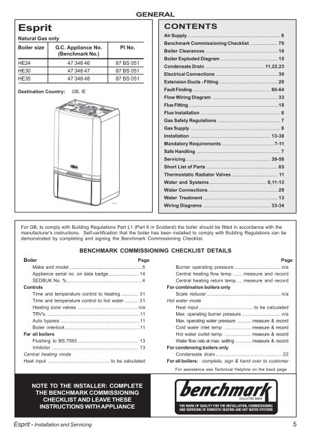
Esprit<br />
Natural Gas only<br />
Boiler size G.C. Appliance No.<br />
(Benchmark No.)<br />
PI No.<br />
HE24 47 348 46 87 BS 051<br />
HE30 47 348 47 87 BS 051<br />
HE35 47 348 48 87 BS 051<br />
Destination Country: GB, IE<br />
Esprit - Installation and Servicing<br />
Esp8896(1)<br />
Boiler Page<br />
Make and model .......................................................5<br />
Appliance serial no. on data badge ...................... 14<br />
SEDBUK No. % .........................................................4<br />
Controls<br />
Time and temperature control to heating ............. 31<br />
Time and temperature control to hot water .......... 31<br />
<strong>Heating</strong> zone valves ..............................................n/a<br />
TRV's ....................................................................... 11<br />
Auto bypass ............................................................ 11<br />
Boiler interlock ........................................................ 11<br />
For all boilers<br />
Flushing to BS.7593 .............................................. 13<br />
Inhibitor .................................................................. 13<br />
Central heating mode<br />
Heat input ................................................to be calculated<br />
GENERAL<br />
CONTENTS<br />
Air Supply ....................................................................... 8<br />
Benchmark Commissioning Checklist ..................... 70<br />
Boiler Clearances ....................................................... 10<br />
Boiler Exploded Diagram ............................................ 15<br />
Condensate Drain .............................................11,22,23<br />
Electrical Connections ............................................... 30<br />
Extension Ducts - Fitting ............................................. 20<br />
Fault Finding ........................................................... 60-64<br />
Flow Wiring Diagram .................................................. 33<br />
Flue Fitting .................................................................... 18<br />
Flue Installation ............................................................. 8<br />
Gas Safety Regulations ................................................ 7<br />
Gas Supply ..................................................................... 8<br />
Installation ............................................................. 13-38<br />
Mandatory Requirements ........................................ 7-11<br />
Safe Handling ................................................................ 7<br />
Servicing ................................................................ 39-58<br />
Short List of Parts ....................................................... 65<br />
Thermostatic Radiator Valves ................................... 11<br />
Water and Systems ........................................... 8,11-13<br />
Water Connections ..................................................... 29<br />
Water Treatment ......................................................... 13<br />
Wiring Diagrams ................................................... 33-34<br />
For GB, to comply with Building Regulations Part L1 (Part 6 in Scotland) the boiler should be fitted in accordance with the<br />
manufacturer's instructions. Self-certification that the boiler has been installed to comply with Building Regulations can be<br />
demonstrated by completing and signing the Benchmark Commissioning Checklist.<br />
BENCHMARK COMMISSIONING CHECKLIST DETAILS<br />
NOTE TO THE INSTALLER: COMPLETE<br />
THE BENCHMARK COMMISSIONING<br />
CHECKLIST AND LEAVE THESE<br />
INSTRUCTIONS WITH APPLIANCE<br />
Page<br />
Burner operating pressure ....................................n/a<br />
Central heating flow temp. ...... measure and record<br />
Central heating return temp. ... measure and record<br />
For combination boilers only<br />
Scale reducer .........................................................n/a<br />
Hot water mode<br />
Heat input ..........................................to be calculated<br />
Max. operating burner pressure ..............................n/a<br />
Max. operating water pressure ........... measure & record<br />
Cold water inlet temp ..................... measure & record<br />
Hot water outlet temp. .................... measure & record<br />
Water flow rate at max. setting ............ measure & record<br />
For condensing boilers only<br />
Condensate drain .................................................. 22<br />
For all boilers: complete, sign & hand over to customer<br />
For assistance see Technical Helpline on the back page<br />
5