i141 USER MANUAL - SIC-Venim s.r.o.
i141 USER MANUAL - SIC-Venim s.r.o.
i141 USER MANUAL - SIC-Venim s.r.o.

You also want an ePaper? Increase the reach of your titles
YUMPU automatically turns print PDFs into web optimized ePapers that Google loves.
<strong>i141</strong><br />
<strong>USER</strong> <strong>MANUAL</strong><br />
<strong>SIC</strong> MARKING<br />
13 route de Limonest<br />
Z.A.C. de la Braille<br />
69380 LISSIEU - FRANCE<br />
Phone : (+33).04.72.54.80.00<br />
Fax : (+33).04.78.47.39.40<br />
E-Mail : info@sic-marking.com<br />
http://www.sic-marking.com<br />
NOTI141US – R00
TABLE OF CONTENTS<br />
TABLE OF CONTENTS 3<br />
PRESENTATION 5<br />
INSTALLATION AND START-UP 7<br />
1. Unpacking...............................................................................................................7<br />
2. Installation ..............................................................................................................7<br />
2.1. Fastening............................................................................................................ 7<br />
2.2. Connections ....................................................................................................... 8<br />
USE OF THE MACHINE 9<br />
1. Safety......................................................................................................................9<br />
2. Controller................................................................................................................9<br />
3. Software..................................................................................................................9<br />
4. Marking machine.....................................................................................................9<br />
4.1. Positioning and clamping of the part to be marked ............................................. 9<br />
4.2. Machine adjustment ......................................................................................... 10<br />
4.3. Launch / Stop the marking ............................................................................... 10<br />
MAINTENANCE 13<br />
1. Introduction ..........................................................................................................13<br />
2. After-sales service.................................................................................................13<br />
3. Preventive maintenance .........................................................................................14<br />
4. Trouble shooting...................................................................................................15<br />
APPENDIX 17<br />
1. stylus assembly .....................................................................................................19<br />
1.1. General layout (overall dimensions) .................................................................. 19<br />
1.2. General layout (References)............................................................................... 20<br />
1.3. Terminology and references general layout....................................................... 21<br />
1.4. Terminology and references spare parts ........................................................... 21<br />
2. marking machine...................................................................................................23<br />
2.1. General layout (overall dimensions) .................................................................. 23<br />
2.2. I 141 Terminology and references..................................................................... 24<br />
NOTI141US – R00 3/30
2.3. Terminology and references X-Y table .............................................................. 26<br />
2.4. electrical chart.................................................................................................. 28<br />
2.5. External connection cables (5 or 10 meters)...................................................... 29<br />
2.6. Internal cabling plan ......................................................................................... 30<br />
NOTI141US – R00 4/30
PRESENTATION<br />
Thank you for choosing a dot marking system (also called micro-percussion) for your<br />
marking applications.<br />
<strong>SIC</strong> MARKING systems contribute to improve the tracability of your products while<br />
complying with the industrial standards.<br />
We would like to welcome you as a user of our systems.<br />
This guide contains the installation and use instructions of the dot marking type<br />
machines. We recommend that you read it carefully before installing the system.<br />
Please contact our technical department for any further information.<br />
NOTI141US – R00 5/30
NOTI141US – R00 6/30
INSTALLATION AND START-UP<br />
1. UNPACKING<br />
Except if we deliver the system, it is generally supplied in an appropriate packaging,<br />
which needs to be kept for any return of the material.<br />
Remove the sub-systems carefully (controller, control handbox, possible options …) from<br />
their packages.<br />
The machine should only be lifted by the column and the<br />
base ; it should never be lifted by the head housing.<br />
Weight of the machine : 35 kg<br />
2. INSTALLATION<br />
2.1. Fastening<br />
Column-type machines<br />
o Install the machine on a rigid and stable support frame<br />
o After installing the entire marking machine, fasten the base with 2 M10<br />
screws.<br />
Integrated-type machines<br />
o Install the machine on a rigid and stable support frame<br />
o Fasten the marking head onto the machine by complying with the<br />
indications of the integration plan, available thread length 12 mm max.<br />
Portable-type machines<br />
o No fastening : marking gun designed to be held manually<br />
Note : The integrated and portable type machines are designed to function in all<br />
positions (vertical, horizontal, stylus towards the bottom or the top)<br />
NOTI141US – R00 7/30
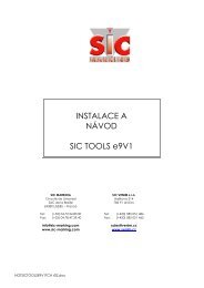
2.2. Connections<br />
• Using the SUB-D 25 connector, connect the marking machine to the "marker"<br />
connector located at the rear of the controller. For the integrated type machines,<br />
proceed the same way using a connection cable.<br />
• Correctly fasten the screws of the connector.<br />
Note : for more details about the connections, please check the controller manual.<br />
Never unplug the controller when it is under tension as<br />
it may seriously damage the material.<br />
switch on / off<br />
power supply<br />
Accessory<br />
(3 rd axis)<br />
MARKER<br />
I / O<br />
START / STOP<br />
KEYBOARD<br />
SERIAL<br />
HOST<br />
control handbox<br />
PC<br />
(port COM1)<br />
mechanical part<br />
keyboard (option)<br />
NOTI141US – R00 8/30
USE OF THE MACHINE<br />
1. SAFETY<br />
An intense use may cause the temperature of the<br />
system to rise up to 100°C.<br />
It is recommended to wear safety glasses.<br />
It is also recommended to wear a noise reducing<br />
helmet.<br />
Acoustic value of the machine : 76 dB on a piece of<br />
steel at medium speed<br />
The marking system should never be used without any<br />
surface to mark as the marking head may break.<br />
2. CONTROLLER<br />
See controller manual<br />
3. SOFTWARE<br />
See software manual<br />
4. MARKING MACHINE<br />
4.1. Positioning and clamping of the part to be marked<br />
Even if the part is not submitted to high forces, it is necessary to immobilize it in order to<br />
reach an optimal marking quality.<br />
NOTI141US – R00 9/30
Depending on the type of parts and the working conditions, the clamping system can vary<br />
from the simple manual fastening of the part against an angle iron (bracket) to the<br />
mechanical, magnetic or pneumatic fastening.<br />
When using a marking gun, place the universal non-skid support against the surface to<br />
be marked and manually hold the gun during the marking.<br />
The fastening device should maintain the part so that the stylus movements are parallel<br />
to the surface to be marked.<br />
For the portable type machines, if the marking is always conducted on the same type of<br />
parts, we advise you to make a customized tooling to always keep the same marking<br />
position.<br />
4.2. Machine adjustment<br />
The marking quality highly depends on the part to be marked ; a smooth and flat surface<br />
is much easier to mark than a rough and irregular surface.<br />
It is generally necessary to adapt the marking force to the height of the character. The<br />
smaller the character is, the lower the impact has to be to obtain a good legibility. The<br />
software also enables to choose various widths for the marking matrix.<br />
To obtain a good marking quality, it is fundamental to adjust the force and the distance.<br />
When using marking guns, the distance between the stylus and the part can be modified<br />
by adjusting the position of the front plate.<br />
For your information, hereafter are some values about the distance between the stylus<br />
and the part depending on the marking force :<br />
Force 1 2 3 4 5 6 7 8 9<br />
Minimum distance 0.5 0.5 0.5 1 1 2 3 5 6<br />
Maximum distance 1 2 3 5 6 7 9 9 9<br />
Maximum distance between the stylus and the part : 9 mm<br />
We recommend that you make trials before marking a new part.<br />
4.3. Launch / Stop the marking<br />
o Set the controller in marking mode (for more information, please see the software<br />
manual)<br />
NOTI141US – R00 10/30
o Position the part to be marked<br />
o Launch the marking by pressing the "Start" button on the control handbox or the<br />
"Marche" button on the gun handle (portable type machine)<br />
o To stop the marking, press the "Stop" button on the control handbox or press the<br />
"Marche" button of the gun handle for more than 2 seconds.<br />
NOTI141US – R00 11/30
NOTI141US – R00 12/30
MAINTENANCE<br />
1. INTRODUCTION<br />
Dot marking machines have been developed and realized especially to meet the needs<br />
of our clients who want a machine which is :<br />
- Performing,<br />
- Robust,<br />
- Reliable,<br />
- Ergonomic.<br />
It requires very little maintenance and if you observe the preventive maintenance<br />
recommendations, you will increase the life-expectancy of your machine.<br />
However, if a problem of any kind should occur, please refer to this manual, which will<br />
help you solve the problem.<br />
2. AFTER-SALES SERVICE<br />
Please contact our local distributor first.<br />
To find out about our local distributor, you can check our website :<br />
www.sic-marking.com<br />
If you can not reach our distributor, please call <strong>SIC</strong> MARKING at +33.4.72.54.80.00.<br />
<strong>SIC</strong> MARKING or its distributor offer the following services :<br />
Phone support<br />
Please do not hesitate to contact us for any technical problem.<br />
On-site intervention<br />
We can help you install, set up the machine on-site, as well as repair it and provide<br />
personal training.<br />
Maintenance contract<br />
Thanks to the maintenance contract, we provide regular maintenance of your marking<br />
machine.<br />
NOTI141US – R00 13/30
3. PREVENTIVE MAINTENANCE<br />
If you want to keep your machine in a good working condition, it is necessary to do the<br />
following actions :<br />
- clean the stylus pin guide and the stylus assembly regularly<br />
- avoid dust and abrasive particles on the guiding and driving elements<br />
How to clean the stylus pin guide and the stylus assembly<br />
- Unplug the marking machine<br />
- Unscrew the stylus pin guide (see General layout of the stylus assembly in<br />
appendix)<br />
- Remove the stylus, the spring and the core<br />
- Clean all parts and remove the grease<br />
- Lubricate the stylus and the stylus pin guide using exclusively the oil supplied<br />
with your maintenance kit.<br />
- Reassemble the machine and manually fasten the stylus pin guide<br />
Note : please pay attention to the direction when reassembling the core (see General<br />
layout of the stylus assembly in appendix)<br />
NOTI141US – R00 14/30
4. TROUBLE SHOOTING<br />
Problem Check Solution<br />
The stylus assembly does not<br />
move on the X and Y axes<br />
The marking head does not go<br />
back home before marking<br />
The stylus assembly moves<br />
(X,Y) but the stylus does not<br />
The marking quality is terrible :<br />
- The dots are not aligned<br />
Check that :<br />
- The controller is on<br />
- A marking program is loaded and the controller<br />
is in marking mode (see software manual)<br />
- The machine is correctly linked to the controller<br />
- The cable is in working condition<br />
- The control handbox is connected (except for<br />
gun marking machines)<br />
- The movements on the X and Y axes are not<br />
blocked when the machine is on.<br />
Check that :<br />
- The sensors cables are correctly connected and<br />
in good working condition<br />
- The origin sensors work properly (in home<br />
position, the red lights located on the sensors<br />
are off, otherwise they are on).<br />
- The driving belts are not broken on the<br />
integrated type or column type machines<br />
Check that :<br />
- The stylus is not blocked by anything<br />
- The solenoid is in good working condition (no<br />
overheating, short circuit…)<br />
Check that :<br />
- The part is correctly maintained during the entire<br />
marking process and the machine is correctly<br />
fastened<br />
- The marking speed is not too high compared<br />
with the marking to be made (size)<br />
- There is no backlash in the X and Y axes<br />
- See controller manual<br />
- Load a program and set the machine in marking<br />
mode<br />
- Reposition the connectors<br />
- Open the connectors and check the wires either<br />
visually or with a ohmmeter.<br />
- Reposition the connectors<br />
- Remove any obstacle or clean the guiding rails<br />
and the driving mechanisms<br />
- Reconnect the wires or replace the damaged<br />
cables<br />
- Replace the sensors<br />
- Replace the damaged belt<br />
- Disassemble the machine, clean it, lubricate it<br />
with the oil provided in your maintenance kit and<br />
re-assemble (see General layout in appendix)<br />
- Replace the solenoid<br />
- Redo the marking after fastening the part and/or<br />
the machine properly<br />
- Reduce the marking speed<br />
- Please contact the after sales service<br />
- The impacts are not<br />
regular<br />
- The distance between the stylus and the part is<br />
correct<br />
- The stylus pin is in good working condition<br />
- The stylus can move correctly<br />
- There is no backlash between the stylus pin<br />
guide and the stylus<br />
- Change the distance (see manual)<br />
- Replace the stylus<br />
- Clean the stylus pin guide and the stylus<br />
- Change the stylus pin guide<br />
If you have checked everything and the system still does not work, please contact our<br />
after sales services.<br />
NOTI141US – R00 15/30
APPENDIX<br />
NOTI141US – R00 17/30
NOTI141US – R00 18/30
1. STYLUS ASSEMBLY<br />
1.1. General layout (overall dimensions)<br />
NOTI141US – R00 19/30
1.2. General layout (References)<br />
NOTI141US – R00 20/30
1.3. Terminology and references general layout<br />
REF QTY CODE DESCRIPTION<br />
1 1 Body<br />
2 1 Solenoid<br />
3 1 Core<br />
4 1 Support mount<br />
5 1 Stylus guide l 60<br />
6 1 Stylus pin l 60<br />
10 1 Spring<br />
11 1 O ring<br />
12 1 Locking O ring<br />
1.4. Terminology and references spare parts<br />
REF QTY CODE DESCRIPTION<br />
1 à 4 1 3 200 003 Solenoid assembly<br />
6 1 1 120 012 Stylus pin L 60<br />
5 1 1 120 017 Stylus guide L 60<br />
1 1 120 013 Stylus pin L 80<br />
1 1 120 023 Stylus guide L 80<br />
1 1 120 014 Stylus pin L 100<br />
1 1 120 024 Stylus guide L 100<br />
10 1 2 120 006 Spring<br />
NOTI141US – R00 21/30
NOTI141US – R00 22/30
2. MARKING MACHINE<br />
2.1. General layout (overall dimensions)<br />
NOTI141US – R00 23/30
2.2. I 141 Terminology and references<br />
NOTI141US – R00 24/30
REF QTY CODE DESCRIPTION<br />
1 4 100 312 X-Y mechanism<br />
1 1 220 073 Cover with identification<br />
1 3 100 040 Power cable<br />
2 1 310 010 Side cap<br />
1 3 100 037 Intermediate cable<br />
2 3 100 038 X and Y motor cable<br />
1 1 220 017 Sheet metal 2 way connector support<br />
1 1 310 014 Carriage and support frame<br />
1 1 110 093 Bracket<br />
1 1 110 094 table fixation plate<br />
1 1 120 096 fixation plate<br />
1 1 110 095 bellow support<br />
1 1 220 074 bellow 1<br />
1 1 220 075 bellow 2<br />
1 1 220 076 bellow 3<br />
1 1 220 077 bellow 4<br />
1 1 220 078 bellow 5<br />
1 1 220 080 bellow 6<br />
2 1 220 079 bellow support bracket<br />
2 2 120 090 pin ∅5 x 20<br />
NOTI141US – R00 25/30
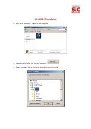
2.3. Terminology and references X-Y table<br />
NOTI141US – R00 26/30
REF QTY CODE DESCRIPTION<br />
16 1 1 110 066 X axis mount<br />
11 1 1 110 067 Y axis mount<br />
12 1 1 110 068 Y chariot<br />
19 1 1 220 057 X motor mount<br />
14 1 1 220 058 Y motor mount<br />
21 1 1 220 058 X lead screw support<br />
23 1 1 220 059 Y lead screw support<br />
6 2 1 120 073 Bushing<br />
13 1 4 100 318 X axis lead screw + nut mount<br />
8 1 4 100 319 Y axis lead screw + nut mount<br />
22 1 2 120 018 X guiding rail<br />
24 1 2 120 016 Y guiding rail<br />
15 1 2 230 055 Wired X motor<br />
18 1 2 230 054 Wired Y motor<br />
7 2 2 120 021 608ZZ ball bearing<br />
5 2 2 120 080 Bearing<br />
17 2 2 110 003 Pressure screw<br />
1 2 1 120 019 Washer<br />
10 2 2 120 010 Motor pulley<br />
2 2 2 120 011 Axis pulley<br />
9 1 2 120 023 X driving belt<br />
3 1 2 120 035 Y driving belt<br />
20 2 2 230 004 Origin sensor<br />
4 2 2 120 022 Seal<br />
25 1 2 110 005 detection screw<br />
26 1 2 110 006 pin ∅4x32<br />
NOTI141US – R00 27/30
2.4. electrical chart<br />
NOTI141US – R00 28/30
2.5. External connection cables (5 or 10 meters)<br />
SUB D 25 19 pins<br />
color<br />
color<br />
element<br />
connector connector (standard cable) (ROBOTIC cable)<br />
1 12 purple green & brown solenoid 1<br />
2 12 black green & white solenoid 1<br />
4 3 brown & gray red & brown Y axis motor<br />
5 4 whie & gray red & white Y axis motor<br />
6 5 brown blue & brown Y axis motor<br />
7 7 white blue & white Y axis motor<br />
8 8 yellow pink X axis motor<br />
9 9 green gray X axis motor<br />
10 10 brown & green pink & white X axis motor<br />
11 11 green & white pink & gray X axis motor<br />
12 1 pink white start / stop button<br />
13 2 gray brown start / stop button<br />
14 12 red yellow solenoid 1<br />
15 12 blue green solenoid 1<br />
16 18 white & yellow red & blue Dallas bus<br />
17 13 red & blue red "L" & "+" sensors<br />
18 14 pink & gray blue "-" sensors<br />
19 17 yellow & brown gray & pink Dallas ground<br />
20 15 red & white black Y sensor<br />
21 16 red & brown purple X sensor<br />
22 6 blue & white yellow & brown solenoid 2<br />
23 6 brown & blue yellow & white solenoid 2<br />
24 6 pink & brown white & gray solenoid 2<br />
25 6 pink & white gray & brown solenoid 2<br />
NOTI141US – R00 29/30
2.6. Internal cabling plan<br />
19 pins<br />
8 pins<br />
12 pins<br />
color<br />
element<br />
connector connector connector<br />
3 1 gray & pink Y axis motor (red)<br />
4 2 green Y axis motor (yellow)<br />
5 3 gray Y axis motor (blue)<br />
6 9 blue solenoid 2<br />
7 4 red & blue Y axis motor (orange)<br />
8 1 black X axis motor (red)<br />
9 2 white & gray X axis motor (yellow)<br />
10 3 white & green X axis motor (orange)<br />
11 4 white & yellow X axis motor (blue)<br />
12 8 green & yellow solenoid 1<br />
13 5 yellow & brown "L" & "+" sensors<br />
13 5 yellow & brown "L" & "+" sensors<br />
14 6 brown & green "-" sensors<br />
14 6 brown & green "-" sensors<br />
15 7 yellow Y sensor<br />
16 7 white X sensor<br />
17 11 brown & gray Dallas ground<br />
18 12 white & red Dallas bus<br />
NOTI141US – R00 30/30