Coil Spring Conversion Range Rover Classic ... - Paddock Spares
Coil Spring Conversion Range Rover Classic ... - Paddock Spares
Coil Spring Conversion Range Rover Classic ... - Paddock Spares

Create successful ePaper yourself
Turn your PDF publications into a flip-book with our unique Google optimized e-Paper software.
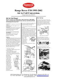
<strong>Coil</strong> <strong>Spring</strong> <strong>Conversion</strong> <strong>Range</strong> <strong>Rover</strong> <strong>Classic</strong> 1993-1995<br />
WARNING! Air suspension is pressurized at 145 psi<br />
WARNING! Wear safety goggles; ear and hand protection!<br />
Vehicle must be on level ground or lift.<br />
Air suspension must be deactivated and depressurized.<br />
How to Deactivate the System.<br />
On 1993 and 1994 models:<br />
1) Turn off disable switch prior to jacking or putting on lift.<br />
2) Remove 30amp compressor fuse.<br />
3) Locate the air suspension delay relay under the right front seat. Find the white/green<br />
wire at terminal 86 and trace this wire until it splits off. Cut the wire after the splice and tape<br />
off both ends. This will deactivate the control buttons light.<br />
4) The system is now deactivated.<br />
On 1995 models:<br />
1) Turn off disable switch prior to jacking or putting on lift.<br />
2) disconnect the Electronic Air Suspension (EAS) ECU located under the right front<br />
passenger seat .by unplugging the large black 35 pin connector.<br />
3) The system is now deactivated.<br />
AEW <strong>Paddock</strong> Motors Ltd, The Showground, The Cliff, Maltock, Derbyshire DE4 5EW, UK<br />
Tel: +44 (0) 1629 760877 Fax: +44 (0) 1629 584498 E-mail: sales@paddockspares.com<br />
www.paddockspares.com
1) Jack or lift the vehicle so the wheels are off the ground. If working on the ground<br />
use jack stands under the chassis for support. Remove all the wheels.<br />
2) Locate the air tank (under LH side of vehicle) open the drain plug approximately<br />
two turns and let the system drain. Once the system has drained, tighten the drain plug.<br />
3) Locate the compressor and valve block assembly (located on the RH side of the<br />
vehicle mounted on the chassis), remove the plastic cover using a 5/16” socket or wrench to<br />
gain access to the valve block.<br />
4) On valve block slowly remove the line from port #2 this will depressurize the right<br />
rear side, once the air bladder is deflated reinstall the line into the valve block port #2.<br />
5) Support the axle housing (right rear) with a jack or T-stand remove the shock from<br />
the top mount. Remove the clips from the top and bottom of the air bladder. Jet the pressure<br />
off of the jack or T-stand, as you remove the bladder disconnect the air line from the top of<br />
the bladder, Plug the air line to a ¼”rubber plug and tack the line out of the way with a<br />
6”plastic tie.<br />
6) Place the spring seat (part #RNH058) on the rear axle, place the rear spring (part<br />
#RNS041 – yellow\red\pink paint.) onto mount area. Make sure the mount holes of the spring<br />
seat and axle mount are aligned place two each 10mm washers over the hose. Place spring<br />
retainer plate (part #RNH06I) through the spring install two each 10mm bolts and nuts. Do<br />
Not Tighten At This Time.<br />
7) Turn the spring clockwise until the spring retainer is touching both sides of the<br />
spring; tighten the bolts. Raise the axle making sure to watch the top of the spring seat into<br />
the frame. Reinstall the top of the shock to the mount.<br />
8) Follow the same procedures for the left rear, except remove air line from port #1 at<br />
the valve block.<br />
9) Now for the left front. Remove the air line from port #3 on the valve block. When<br />
line is depressurized reconnect<br />
10) Remove the plastic cover (LF). Remove the air line from the top of the air bladder.<br />
Plug line with a ¼” rubber plug and Lay the line out of<br />
the way with a 6” plastic tie.<br />
11) Support the front axle with jack stand or T-stand.<br />
12) Remove the clips from the top and bottom of the air bladder and remove the air<br />
bladder. Remove the heat shield from the top of the spring mount and the plastic fastener or<br />
the spring will not seat properly.<br />
13) Remove the two 10mm nuts that hold the brake line bracket to the wheel well.<br />
1 4) disconnect the top of the shock from the shock mount then let the front axle down.<br />
Install the spring seat (part #RNH058), on the axle<br />
install the left front spring (part #RNS050 – yellow\white paint). Follow the same directions<br />
mentioned above in #11 and #12.
15) Reinstall the brake line bracket and tighten nuts; reinstall the plastic cover.<br />
I 6) The right front is to he done the same as the left front, except remove the air line<br />
from port #4 on the valve block. The right front spring part number is RNS051<br />
(yellow/yellow paint).<br />
17) Once all the air bladders have been replaced with the coil springs take a look and<br />
make sure the springs are seated properly and everything is tight.<br />
18) Reinstall the plastic cover on the valve block.<br />
19) Reinstall the four wheels and torque to 85 ft/lbs.<br />
20) The vehicle will sit approx 1” higher than standard height.<br />
IMPORTANT! The vehicle must be road tested, check for any suspension noises.<br />
Re-torque the wheels once the vehicle has been driven between 15-25 miles.<br />
AEW <strong>Paddock</strong> Motors Ltd, The Showground, The Cliff, Maltock, Derbyshire DE4 5EW, UK<br />
Tel: +44 (0) 1629 760877 Fax: +44 (0) 1629 584498 E-mail: sales@paddockspares.com<br />
www.paddockspares.com