STEPPER MOTOR CONTROLLER - AVRcard
STEPPER MOTOR CONTROLLER - AVRcard
STEPPER MOTOR CONTROLLER - AVRcard

Create successful ePaper yourself
Turn your PDF publications into a flip-book with our unique Google optimized e-Paper software.
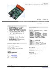
<strong>AVRcard</strong><br />
Building Blocks for Designers of Digital Products<br />
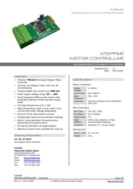
<strong>STEPPER</strong><br />
<strong>MOTOR</strong> <strong>CONTROLLER</strong><br />
Microstep Motor Controller for the I2C Bus<br />
Datasheet Rev.: 1.2<br />
Date: 09.10.2009<br />
Features<br />
<br />
<br />
<br />
<br />
<br />
<br />
<br />
<br />
<br />
<br />
<br />
<br />
Trinamic TMC222 Microstep Stepper Motor<br />
Controller<br />
Controls one stepper motor with four bit<br />
microstepping<br />
Programmable coil current up to 800 mA<br />
Motor supply voltage range: 8V ... 29V<br />
Fixed frequency PWM current control with<br />
automatic selection of fast and slow decay<br />
mode<br />
Full step frequencies up to 1 kHz<br />
High temperature, open circuit, short, overcurrent<br />
and under-voltage diagnostics<br />
Internal 16-bit wide position counter<br />
Configurable speed and acceleration settings<br />
Built-in ramp generator for autonomous<br />
positioning and speed control<br />
On-the-fly alteration of target position<br />
Reference switch input available for read out<br />
Ordering Information<br />
Art.-No. 01.0018<br />
I2C Stepper Motor Controller<br />
Specifications<br />
Motor Interface<br />
Supply<br />
Voltage<br />
Coil Current<br />
Step<br />
Frequency<br />
Connector<br />
MCU Interface<br />
Bus Type<br />
Bus Speed<br />
Signal levels<br />
Node<br />
address<br />
Connector<br />
Mechanical<br />
Size (L x W)<br />
Weight<br />
8…29VDC<br />
Max. 800mA<br />
Max. 1kHz<br />
Industry standard 8-way Weidmüller<br />
(BL3.5/8)<br />
I2C (SCL, SDA)<br />
Up to 350kHz<br />
TTL<br />
0x00, 0xC0 (default), 32 field<br />
programmable addresses<br />
Standard 0.1” 10-way header<br />
47 x 32 mm<br />
25 g<br />
Contact:<br />
Elektronik-Atelier Kallen<br />
Giacomettistrasse 33A<br />
CH-3006 Bern / Switzerland<br />
Web: www.avrcard.com<br />
Email: info@avrcard.com<br />
Tel: +41-31-832 1441<br />
Fax: +41-31-560 4110<br />
<strong>STEPPER</strong><br />
<strong>MOTOR</strong> <strong>CONTROLLER</strong> - Datasheet Page 1/5<br />
Rev.1.2 - 09.10.2009 © 2009 by Elektronik-Atelier Kallen www.avrcard.com
<strong>AVRcard</strong><br />
Building Blocks for Designers of Digital Products<br />
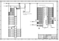
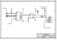
Connector Specifications<br />
Figure 1 – Connectors<br />
Power Supply<br />
and Motor,<br />
(X2)<br />
Address Selection (J1)<br />
Pin 8<br />
MCU<br />
Interface,<br />
(X2)<br />
Pin 1<br />
Pin 1<br />
MCU Interface<br />
X1: MCU Interface<br />
No. Function<br />
1<br />
2<br />
3<br />
4<br />
5<br />
6 GND<br />
7<br />
8<br />
9 SCL<br />
10 SDA<br />
Power Supply and<br />
Motor Interface<br />
X2: Power Supply and Motor<br />
No. Function Alt. Function<br />
1 SWI Reference Switch Input 1<br />
2 GND Power GND<br />
3 A1 Motor Coil 1<br />
4 A2 Motor Coil 1<br />
5 B1 Motor Coil 2<br />
6 B2 Motor Coil 2<br />
7 VBAT 8..29VDC Power Supply<br />
8 GND Power GND<br />
X2 Connection diagram. View into<br />
cable entries of connector<br />
8<br />
7<br />
6<br />
5<br />
4<br />
3<br />
2<br />
1<br />
VBAT min = 6.5V for I2C interface operation<br />
VBAT min = 8.5V for motor operation<br />
1 To activate the switch, connect this pin to GND or to VBAT. Leave this pin unconnected to<br />
deactivate the switch.<br />
<strong>STEPPER</strong><br />
<strong>MOTOR</strong> <strong>CONTROLLER</strong> - Datasheet Page 2/5<br />
Rev.1.2 - 09.10.2009 © 2009 by Elektronik-Atelier Kallen www.avrcard.com
<strong>AVRcard</strong><br />
Building Blocks for Designers of Digital Products<br />
Jumper Settings<br />
HW Bit Select<br />
No. Des. LEFT RIGHT<br />
J1 HW HW = 0 HW = 1<br />
Physical Address<br />
on I2C Bus<br />
HW = 0: I2C Slave address = 0xC0<br />
HW = 1: I2C Slave address = 0xC2<br />
The TCM222 supports a “general call” address. Therefore the circuit is addressable<br />
using either the physical slave address or address “000 0000”.<br />
Application Information<br />
Hardware Setup<br />
1. Connect the host microcontroller to X1. Make sure the I2C interface of the<br />
host works in master mode and has appropriate pull-up resistors on the<br />
bus.<br />
2. Set Jumper J1 to left position (HW=0).<br />
3. Connect VBAT on X2<br />
4. Verify that Communication on the I2C bus<br />
I2C Bus<br />
Addressing<br />
A total of 30 devices can be operated in parallel on the same I2C bus. They are<br />
discriminated by means of the physical address. The default address is 0xC0. This<br />
address can be field programmed in the OTP, using the reserved address ‘0’.<br />
All new devices are shipped with the OTP physical address bits set to zero. In order<br />
to program the address, it is therefore necessary to connect only one device at a<br />
time to the bus for programming. Please refer to the TMC222 datasheet for a<br />
description of the programming sequence.<br />
Note: All OTP parameters are programmable only once from ‘0’ to ‘1’.<br />
Motor Functional<br />
Test<br />
Following sequence of I2C commands can be used for testing the module.<br />
Step 1: Get full status<br />
I2COut (TMC222, GetFullStatus1);<br />
Step 2: Set motor parameters<br />
ar[0]:= $FF;<br />
ar[1]:= $FF;<br />
ar[2]:= $55; // Irun, Ihold<br />
ar[3]:= $81; // Vmax, Vmin<br />
ar[4]:= $10; // Shaft = 1<br />
ar[5]:= $00; // SecPos<br />
ar[6]:= $0C; // StepMode<br />
I2COut (TMC222, SetMotorParam, ar);<br />
Step 3: Get full status<br />
I2COut (TMC222, GetFullStatus1);<br />
for i:= 0 to 7 do<br />
I2COut (TMC222, i);<br />
I2CInp (TMC222, v);<br />
Write (SerOut, ByteToHex (v) + ' ');<br />
endfor;<br />
Now, Ihold is flowing into the motor.<br />
<strong>STEPPER</strong><br />
<strong>MOTOR</strong> <strong>CONTROLLER</strong> - Datasheet Page 3/5<br />
Rev.1.2 - 09.10.2009 © 2009 by Elektronik-Atelier Kallen www.avrcard.com
<strong>AVRcard</strong><br />
Building Blocks for Designers of Digital Products<br />
Step 4: Drive motor<br />
ar1[0]:= $FF;<br />
ar1[1]:= $FF;<br />
ar1[2]:= $FF; // Pos byte 1<br />
ar1[3]:= $7F; // Pos byte 2<br />
ar1[4]:= $00; //<br />
ar1[5]:= $00; //<br />
ar1[6]:= $00; //<br />
I2COut (TMC222, SetPosition, ar1);<br />
The motor drives to the set position and is then hold.<br />
Step 5: Reset position<br />
I2COut (TMC222, ResetPosition);<br />
Step 6: Drive Motor again, etc.<br />
Constant definitions used<br />
TMC222: Byte = %1100000;<br />
GetFullStatus1: Byte = $81;<br />
GetFullStatus2: Byte = $FC;<br />
SetMotorParam: Byte = $89;<br />
SetPosition: Byte = $8B;<br />
GetOtpParam: Byte = $82;<br />
ResetDefault: Byte = $87;<br />
ResetPosition: Byte = $86;<br />
<strong>STEPPER</strong><br />
<strong>MOTOR</strong> <strong>CONTROLLER</strong> - Datasheet Page 4/5<br />
Rev.1.2 - 09.10.2009 © 2009 by Elektronik-Atelier Kallen www.avrcard.com
<strong>AVRcard</strong><br />
Building Blocks for Designers of Digital Products<br />
Notice to Users<br />
The intended use of the Stepper modules is described in this document. Other than<br />
the described uses are not permitted or only after consultation with the<br />
manufacturer.<br />
Stepper modules are not authorized for use as critical components in life-support<br />
devices or systems.<br />
Life-support devices or systems are devices or systems intended for surgical<br />
implantation into the body or to sustain life, and whose failure to perform, when<br />
properly used in accordance with instructions for use provided in the labeling and<br />
user’s manual, can be reasonably expected to result in significant injury.<br />
No complex software or hardware system is perfect. Bugs are always present in a<br />
system of any size. In order to prevent danger to life or property, it is the<br />
responsibility of the system designer to incorporate redundant protective<br />
mechanisms appropriate to the risk involved.<br />
All Stepper modules are 100 percent functionally tested. Additional testing may<br />
include visual quality control inspections. Specifications are based on<br />
characterization of tested sample units rather than testing over temperature and<br />
voltage of each unit. Stepper modules may qualify components to operate within a<br />
range of parameters that is different from the manufacturer’s recommended range.<br />
<strong>STEPPER</strong><br />
<strong>MOTOR</strong> <strong>CONTROLLER</strong> - Datasheet Page 5/5<br />
Rev.1.2 - 09.10.2009 © 2009 by Elektronik-Atelier Kallen www.avrcard.com