table of contents - Robitronic
table of contents - Robitronic
table of contents - Robitronic
Create successful ePaper yourself
Turn your PDF publications into a flip-book with our unique Google optimized e-Paper software.
STEP I-01<br />
Intro to the 8IGHT Manual<br />
INTRO<br />
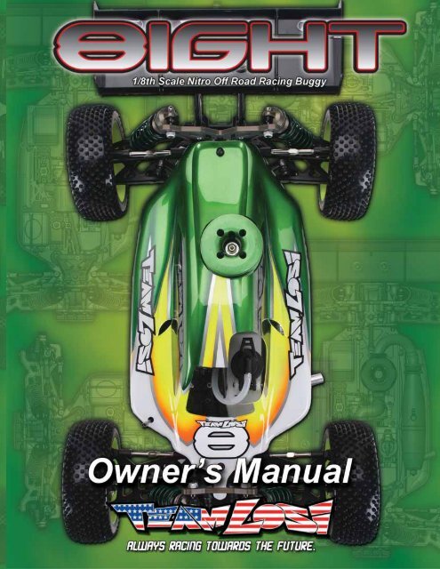
Welcome Team Losi 8IGHT Owner!<br />
Thank you for selecting the 8IGHT as your new racing buggy. The 8IGHT has already distinguished itself as a top caliber racing chassis<br />
and as you will see, we have made every effort to produce a kit that is not only the most competitive but also easy to build and maintain.<br />
The simple bag-by-bag assembly sequence and easily followed instructions and drawings combined with Team Losi’s world famous quality<br />
fitting parts will make building the 8IGHT a most enjoyable project.<br />
Before you open the first bag, or start assembly, please take a moment to read through the following instructions. This will familiarize<br />
you with the various parts, assembly tips, and descriptions as well as the tools needed. Taking an extra moment before starting can save a<br />
good deal <strong>of</strong> time and assure proper assembly.<br />
Good luck and good racing,<br />
Team Losi<br />
8IGHT COMPLETED KIT SPECIFICATIONS<br />
Overall Chassis Length: 16-1/4in (413mm) Wheelbase: 12.64-12.80in (321-325mm) *Front Track Width: 12.13in (308mm)<br />
Overall Length w/Tires: 19-1/4in (489mm) *Overall Height: 6-5/8in (168mm) *Rear Track Width: 12.13in (308mm)<br />
Note: Final kit weight will vary depending on accessories used.<br />
*All measurements taken at ride height (32mm).<br />
Table 1: 8IGHT Completed Kit Specifi cations.<br />
Kit/Manual Organization:<br />
The kit is composed <strong>of</strong> different bags marked A through H. Each<br />
bag contains all <strong>of</strong> the parts necessary to complete a particular section<br />
<strong>of</strong> the kit. Some <strong>of</strong> these bags have sub-assembly bags within<br />
them. It is essential that you open only one bag at a time and follow<br />
the correct assembly sequence, otherwise you may face difficulties in<br />
finding the correct part. It is helpful to read through the instructions<br />
for an entire bag prior to beginning assembly. Next to each <strong>of</strong> the step<br />
numbers is a check box. At the completion <strong>of</strong> each step, place a check<br />
in this box so that if you must stop and come back to the assembly,<br />
you will be able to pick up where you left <strong>of</strong>f.<br />
For your convenience, an actual-size Hardware Identification<br />
Guide is included as a fold-out page at the back <strong>of</strong> this manual. Hardware<br />
that is not easily differentiable in each step is called out with<br />
an icon which contains a small<br />
picture <strong>of</strong> the part genre (referenced<br />
on the Hardware Identification<br />
Guide), the quantity <strong>of</strong><br />
that part required for what is<br />
shown in the step, and the size<br />
or name <strong>of</strong> that part. To check a part, hold it against the silhouette until<br />
the correct part is identified. Associated with each <strong>of</strong> these parts, in<br />
the Hardware Identification Guide, is a LOSA-Number which is used<br />
when ordering replacement parts for your 8IGHT. In some cases, extra<br />
hardware has been supplied for parts that may be easy to lose.<br />
Components used in each step are identified by their relative<br />
LOSA-Number and the component’s name. With the exception <strong>of</strong><br />
a few parts, these are not referenced in the Hardware Identification<br />
Guide.<br />
The molded parts in Team Losi kits are manufactured to demanding<br />
tolerances. When screws are tightened to the point <strong>of</strong> being<br />
snug, the parts are held firmly in place. For this reason, it is very<br />
important that screws not be overtightened in any <strong>of</strong> the plastic<br />
parts.<br />
In some steps there will be a filled black circle with a white<br />
number. These indicate the specific order by which assembly must<br />
occur. In cases where steps are repeated (front/rear or left/right) these<br />
numbers may be omitted. Please note that these numbers will not call<br />
out every sub-step required for the step’s assembly procedures, they<br />
will only highlight the critical order required for assembly.<br />
In each step, there are specific “Detail Icons” (shaped like a stop<br />
sign) that call out critical precautions or assembly tips for the process.<br />
There is a reference key that describes the meaning <strong>of</strong> each <strong>of</strong><br />
the icons located on the fold-out Hardware Identification Guide at<br />
the back <strong>of</strong> this manual.<br />
To ensure that parts are not lost during construction, it is recommended<br />
that you work over a towel or mat to prevent parts from<br />
rolling away.<br />
IMPORTANT SAFETY NOTES:<br />
1. Select an area for assembly that is away from the reach <strong>of</strong> small<br />
children. Some parts in this kit are small and can be swallowed<br />
by children, causing choking and possible internal injury;<br />
PLEASE USE CAUTION!<br />
2. The shock fluid and greases supplied should be kept out <strong>of</strong> children’s<br />
reach. They are not intended for human consumption!<br />
3. Exercise care when using any hand tools, sharp instruments, or<br />
power tools during construction.<br />
4. Carefully read all manufacturer’s warnings and cautions for any<br />
chemicals, glues, or paints that may be used for assembly and<br />
operating purposes.<br />
i
INTRO<br />
TOOLS REQUIRED FOR ASSEMBLY<br />
Team Losi has supplied all necessary Allen wrenches and a special wrenchs that are needed for assembly and adjustments. The following<br />
common tools will also be required: Needle-nose pliers, regular pliers, hobby knife, scissors or other body cutting/trimming tools, and a<br />
soldering iron may be necessary for radio installation. 3/16”, 1/4”, 5/16”, and 11/32” nut drivers are optional.<br />
RADIO/ELECTRONICS<br />
A suggested radio layout is provided in this manual. Your high performance R/C center should be consulted regarding specific questions<br />
pertaining to radio/electrical equipment.<br />
HARDWARE IDENTIFICATION<br />
When in question, use the Hardware Identification Guide at the back <strong>of</strong> this manual.<br />
• For screws, the prefix number designates the thread size and number <strong>of</strong> threads per inch (i.e., 4-40 is a #4 size thread with 40 threads per<br />
inch). The second number, or fraction, designates the length <strong>of</strong> the screw. For cap head and button head screws, this number refers to the<br />
length <strong>of</strong> the threaded portion <strong>of</strong> the screw. For flat head and set screws, this number refers to the overall length <strong>of</strong> the screw.<br />
• Bearings and bushings are referenced by the inside diameter (I.D.) x outside diameter (O.D.).<br />
• Shafts and pins are designated by type (Roll, Solid) and referenced by diameter x length.<br />
• Washers, Spacers and Shims are described by inside diameter or the screw size that will pass through the inside diameter x the thickness<br />
or by their designated application (i.e., Ball Stud washer is primarily used under a Ball Stud).<br />
• Retaining Clips are sized by the shaft diameter that they attach to or by type (Body). The Hardware Icon associated with E/C-Clips only<br />
designates the part genre <strong>of</strong> clips, not the actual part.<br />
• Nuts come in four types, Non-Flanged, Flanged (F), Plain, and Locking (L) (designated on the Hardware Icons). The prefix number designates<br />
the thread size and number <strong>of</strong> threads per inch. The second number, or fraction, designates the size <strong>of</strong> the hex. For example, L 4-40<br />
x 1/4” designates a Lock nut that will thread onto a 4-40 screw using a 1/4” nut driver.<br />
• Setscrews come in three types, Cup (C), Flat (F) and Oval (O) (designated on the hardware Icons). The prefix number designates the thread<br />
size and number <strong>of</strong> thread per inch. The second number, or fraction, designates the length <strong>of</strong> the threade portion <strong>of</strong> the screw.<br />
TABLE OF CONTENTS<br />
SECTIONS<br />
1. INTRODUCTION................................................... i<br />
Kit/Manual Organization ................................... i<br />
Important Safety Notes ...................................... i<br />
Tools Required for Assembly ............................ ii<br />
Radio/Electronics .............................................. ii<br />
Hardware Identification .................................... ii<br />
2. Bag A: Steering Assembly ................................... 1-2<br />
3. Bag B: Front Clip ................................................ 3-8<br />
4. Bag C: Center Transmission .............................. 9-12<br />
5. Bag D: Rear Clip ............................................. 13-18<br />
6. Bag E: Shocks ................................................. 19-21<br />
7. Bag F: Radio Tray ........................................... 22-26<br />
8. Bag G: Engine Installation .............................. 27-30<br />
9. Bag H: Wheels, Tires, Body ............................ 31-34<br />
8. Checklist Before Your First Run ........................35<br />
9. Setup Guide .................................................... 35-39<br />
10. Blank 8IGHT Setup Sheet ...................................24<br />
11. Hardware Identification Guide ...........................25<br />
12. Filled-out 8IGHT Kit Setup Sheet ......................26<br />
TABLES<br />
Table 1: 8IGHT Completed Kit Specifications ............ i<br />
Table 2: Servo Installation .........................................23<br />
Team Losi is continually changing and improving designs; therefore, the actual part may appear slightly different than the illustrated part. Illustrations <strong>of</strong> parts and assemblies<br />
may be slightly distorted to enhance pertinent details.<br />
ii
BAG A<br />
<br />
STEP A-01<br />
Steering Link Assembly<br />
<br />
STEP A-02<br />
Servo Saver Assembly<br />
A9166<br />
Steering Servo Arm<br />
x 1<br />
L 4-40 x 3/16”<br />
x 1<br />
4-40 x 1/2”<br />
A4410<br />
Servo Saver Tube<br />
A6043<br />
Rod End Ball<br />
A6043<br />
Rod End<br />
A4409<br />
Steering Arm<br />
Maintenance Tip<br />
x 1<br />
5-40 x 5/8”<br />
x 1<br />
A4411<br />
Steering Drag Link<br />
x 1<br />
L 4-40 x 3/16”<br />
A4411<br />
Drag Link Screw<br />
4-40 x 1/2”<br />
A4409<br />
Steering Bellcrank R<br />
A4411<br />
Drag Link Bushing<br />
A4409<br />
Steering Bellcrank L<br />
A4410<br />
Servo Saver Spring<br />
2.26"<br />
57.40mm<br />
A4410<br />
Servo Saver Nut<br />
Tighten the Servo Saver<br />
nut all the way down and<br />
then back it <strong>of</strong>f 2 1/2 turns.<br />
<br />
STEP A-03<br />
Fuel Tank/Chassis Brace Assembly<br />
x 2<br />
4-40 x 1/2”<br />
A9160<br />
Fuel Tank<br />
A4424<br />
Fuel Tank Grommet<br />
#4 x .030<br />
x 2<br />
x 3<br />
L 5-40 x 1/4”<br />
A4413<br />
Front Chassis Support<br />
A4408<br />
Steering Post<br />
A4401<br />
Chassis<br />
A4424<br />
Tank Mount<br />
x 6<br />
5-40 x 1/2”<br />
1
STEP A-04<br />
Steering/Top Plate Assembly<br />
BAG A<br />
A4413<br />
Front Chassis Brace<br />
A4424<br />
Front Body Mount<br />
x 1<br />
5-40 x 1/2”<br />
x 2<br />
5-40 x 1/2”<br />
x 1<br />
5-40 x 3/8”<br />
x 4<br />
6x10x3mm<br />
<br />
STEP A-05<br />
Completed Steering Assembly<br />
2
STEP B-01<br />
Ring Gear Assembly<br />
BAG B<br />
<br />
STEP B-03<br />
Complete Diff Assembly<br />
Solid<br />
x 1<br />
2.5 x 12.80mm<br />
A3504<br />
Outdrive Cup<br />
Fill with 5000wt. oil just above<br />
the planetary gear<br />
3<br />
3x12mm<br />
x 4<br />
1<br />
2<br />
x 1<br />
F 8x14x4mm<br />
4<br />
A3509<br />
Ring Gear<br />
A3502<br />
Sun Gear<br />
A3505<br />
O-Ring<br />
A3505<br />
Diff Seal<br />
<br />
STEP B-02<br />
Diff Case Assembly<br />
Solid x 1<br />
2.5 x 12.80mm<br />
3<br />
A3502<br />
Planetary Gear<br />
A3502<br />
Planetary Gear<br />
Axle<br />
x 1<br />
F 8x14x4mm<br />
Tighten the diff screws<br />
in this order<br />
1<br />
1<br />
3<br />
2<br />
A3504<br />
Outdrive Cup<br />
4<br />
2<br />
A3500<br />
Diff Housing<br />
4<br />
A3502<br />
Sun Gear<br />
A3505<br />
O-ring<br />
3
STEP B-04<br />
Front Diff Install<br />
BAG B<br />
•<br />
To prevent fine dust from entering<br />
the gear box, apply a thin<br />
bead <strong>of</strong> grease along the edge<br />
<strong>of</strong> the case as pictured.<br />
x 1<br />
F 8-32 x 1/8”<br />
3<br />
4<br />
x 2<br />
5x11x4mm<br />
A3514<br />
Drive Adapter<br />
6<br />
2<br />
1<br />
A4427<br />
Front Bulkhead<br />
x 2<br />
5-40 x 7/8”<br />
A3508<br />
Pinion Gear, Bevel<br />
x 2<br />
5-40 x 1/2”<br />
5<br />
A4427<br />
Front Diff Cover<br />
<br />
STEP B-05<br />
Front Spindle & CV Assembly<br />
A3521<br />
Dogbone<br />
1<br />
A3523<br />
CV Coupling<br />
Solid<br />
x 1<br />
2.5 x 12.4mm<br />
2<br />
3<br />
x 1<br />
1/2” x 3/4”<br />
A1707<br />
Left Spindle<br />
A3522<br />
Axle<br />
4<br />
x 1<br />
8x14x4mm<br />
6<br />
Solid<br />
x 1<br />
3 x 17mm<br />
A3530<br />
Wheel Hex<br />
x 1<br />
C 8-32 x 1/8”<br />
5<br />
7<br />
4
STEP B-06<br />
Spindle/Carrier Assembly<br />
BAG B<br />
x 1<br />
O 10-32 x 3/8”<br />
2<br />
5<br />
A1700<br />
Left Front Arm<br />
4<br />
4<br />
A1701<br />
Front Arm Bushing<br />
1<br />
2<br />
5<br />
x 2<br />
C 5-40 x 3/16”<br />
3<br />
3<br />
A6050<br />
Steering Ball Stud<br />
x 1<br />
5-40 x 1/4”<br />
A6501<br />
Hinge Pin<br />
A1710<br />
Left Spindle Carrier<br />
x 2<br />
8/32 x 3/4”<br />
<br />
STEP B-07<br />
Front Suspension Arms Assembly<br />
Solid<br />
x 2<br />
4mm x 65mm<br />
A1744<br />
Front Inner Hinge Pin Brace<br />
A4431<br />
Front Inner Hinge Pin Cap<br />
A1744<br />
Front Outer Hinge Pin Brace<br />
x 4<br />
5-40 x 3/4”<br />
A4431<br />
Front Outer Hinge Pin Cap<br />
5
STEP B-08<br />
Swaybar Assembly<br />
BAG B<br />
Install the Swaybar Ball onto the Swaybar Wire<br />
until the end <strong>of</strong> the wire is flush with the ball as<br />
pictured above<br />
x 2<br />
C 5-40 x 1/8”<br />
A1750<br />
Swaybar Link<br />
A1750<br />
Swaybar Ball, Arm<br />
A4426<br />
Swaybar Mount<br />
Cap<br />
x 2<br />
4-40 x 5/8”<br />
x 2<br />
C 4-40 x 1/8”<br />
x 4<br />
2-56 x 1/4”<br />
A1750<br />
Front Swaybar<br />
A1750<br />
Swaybar Ball<br />
<br />
STEP B-09<br />
Tie Rod/Shock Tower Assembly<br />
A1715<br />
Front Shock Tower<br />
A6048<br />
Suspension Ball, Flanged<br />
x 2<br />
L 5-40 x 1/4”<br />
Be sure to install the assembled<br />
Tierod onto the car with the groove<br />
(next to the center square section)<br />
on the driver’s left side for easier<br />
adjustment later.<br />
A4426<br />
Shock Tower<br />
Mount Cap<br />
x 4<br />
5-40 x 1/2”<br />
A5438<br />
Shock Stand-Off<br />
x 2<br />
L 8-32 x 11/32”<br />
A6540<br />
Turnbuckle, Front<br />
A6047<br />
Rod End<br />
A6049<br />
Suspension Ball<br />
x 2<br />
5-40 x 3/4”<br />
5-40 x 1”<br />
x 1<br />
3.72"<br />
94.50 mm<br />
6
STEP B-10<br />
Front Camber Link Assembly<br />
BAG B<br />
Be sure to install the assembled<br />
Tierod onto the car with the groove<br />
(next to the center square section)<br />
on the driver’s left side for easier<br />
adjustment later.<br />
A6542<br />
Steering Turnbuckle<br />
A6046<br />
Steering Rod End<br />
A6050<br />
Steering Ball<br />
3.62"<br />
92.00mm<br />
<br />
STEP B-11<br />
Center CV Assembly<br />
Solid<br />
A3526<br />
CV Coupling, Center<br />
x 1<br />
2.5mm x 14mm<br />
3<br />
A3526<br />
Driveshaft, Center<br />
1<br />
2<br />
x 1<br />
F 5-40 x 1/8”<br />
7
STEP B-12<br />
Front Clip Assembly<br />
BAG B<br />
x 2<br />
5-40 x 3/4”<br />
x 2<br />
5-40 x 3/4”<br />
4<br />
1<br />
3<br />
A4426<br />
Front Bulkhead Space<br />
2<br />
A4422<br />
Front Bumper<br />
x 4<br />
8-32 x 1/2”<br />
<br />
STEP B-13<br />
Completed Front Assembly<br />
8
STEP C-01<br />
Ring Gear Assembly<br />
BAG C<br />
<br />
STEP C-03<br />
Complete Diff Assembly<br />
Solid x 1<br />
2.5 x 12.80mm<br />
Fill with 7000wt.<br />
oil just above the<br />
planetary gear<br />
3<br />
1<br />
A3502<br />
Sun Gear<br />
2<br />
3x12mm<br />
x 4<br />
4<br />
A3506<br />
Center Outdrive<br />
A3505<br />
O-ring<br />
x 1<br />
F 8x14x4mm<br />
A3516<br />
Spur Gear<br />
A3505<br />
Diff Seal<br />
A3502<br />
Planetary Gear Axle<br />
<br />
STEP C-02<br />
Diff Case Assembly<br />
A3502<br />
Planetary Gear<br />
A3502<br />
Sun Gear<br />
A3505<br />
O-ring<br />
A3500<br />
Diff Housing<br />
A3506<br />
Center Outdrive<br />
4<br />
2<br />
1<br />
Tighten the diff screws<br />
in this order<br />
3<br />
x 1<br />
F 8x14x4mm<br />
1<br />
4<br />
Solid x 1<br />
2.5 x 12.80mm<br />
3<br />
2<br />
9
STEP C-04<br />
(.5mm)(.020)<br />
2<br />
Center Top Brace Assembly<br />
A4415<br />
Top Brace,<br />
Center Diff<br />
x 1<br />
5mm E-Clip<br />
BAG C<br />
x 2<br />
5-40 x 1/8”<br />
<br />
STEP C-05<br />
Linkage Assembly<br />
A9166<br />
Front Brake Actuator<br />
A9166<br />
Threaded Servo Rod<br />
A9166<br />
Throttle Rod End<br />
2-56 x 1/2”<br />
A9166<br />
Rear Brake Rod<br />
x 1<br />
2-56 x 1/4”<br />
x 1<br />
x 2<br />
.250x.094x020<br />
x 3<br />
C 4-40 x 1/8”<br />
A3544<br />
Brake Cam Bushing<br />
1<br />
1<br />
A3544<br />
Front Brake Cam<br />
A9166<br />
Brake Wire<br />
A9166<br />
Throttle Return Spring<br />
A9166<br />
Threaded Servo Rod<br />
A9166<br />
Throttle Servo Arm<br />
A9166<br />
Throttle Actuator<br />
A9166<br />
Brake Lever Collar<br />
A9166<br />
Rear Brake Actuator<br />
A3544<br />
Rear Brake Cam<br />
A9166<br />
Adjuster Collar<br />
(7mm)<br />
(.2760in)<br />
2<br />
<br />
STEP C-06<br />
Linkage Assembly<br />
<br />
STEP C-07<br />
Air Filter Mount & Guard<br />
x 2<br />
C 4-40 x 1/8”<br />
A9166<br />
Brake Lever<br />
Collar<br />
A9166<br />
Brake Bushing<br />
(9mm)<br />
(.3545in)<br />
Cut two pieces<br />
<strong>of</strong> fuel tubing<br />
to size pictured<br />
A4422<br />
Air Filter Guard<br />
A9150<br />
Air Filter Mount<br />
x 2<br />
.250x.094x.020<br />
A9315<br />
Fuel Line<br />
x 5<br />
5-40 x 3/8”<br />
Assemble both Front and<br />
Rear Brake Lever Collars<br />
2.80mm (.11”) from the<br />
end <strong>of</strong> the Brake Rod.<br />
A4422<br />
Tank Guard<br />
10
STEP C-08<br />
Brake Caliper Assembly<br />
BAG C<br />
A3541<br />
Rear Brake Pad<br />
A3541<br />
Front Brake Pad<br />
0.230"<br />
5.80mm<br />
A4415<br />
Front Center Diff Mount<br />
A3541<br />
Brake Shoulder Screw<br />
A4415<br />
Rear Center Diff Mount<br />
<br />
STEP C-09<br />
Center Diff/Brake Rotor Assembly<br />
4<br />
x 4<br />
5-40 x 3/8”<br />
3<br />
2<br />
A4415<br />
Bearing Insert<br />
A3540<br />
Front Brake Disk<br />
A3540<br />
Rear Brake Disk<br />
3<br />
1<br />
1<br />
11
STEP C-10<br />
Center Diff Installation<br />
BAG C<br />
Caution! Ensure that the<br />
driveshaft is inserted into the<br />
slot <strong>of</strong> the center outdrive<br />
while installing the Center Diff.<br />
assembly.<br />
x 4<br />
8-32 x 1/2”<br />
<br />
STEP C-11<br />
Completed Center Diff Assembly<br />
12
STEP D-01<br />
Ring Gear Assembly<br />
BAG D<br />
<br />
STEP D-03<br />
Complete Diff Assembly<br />
A3504<br />
Outdrive Cup<br />
Fill with 2000wt.<br />
oil just above the<br />
planetary gear<br />
Solid x 1<br />
2.5 x 12.80mm<br />
3<br />
x 1<br />
F 8x14x4mm<br />
1<br />
3x12mm<br />
x 4<br />
4<br />
2<br />
A3502<br />
Sun Gear<br />
A3505<br />
O-ring<br />
A3510<br />
Rear Ring Gear<br />
A3505<br />
Diff Seal<br />
A3502<br />
Planetary Gear<br />
<br />
STEP D-02<br />
Diff Case Assembly<br />
A3502<br />
Sun Gear<br />
Solid<br />
x 1<br />
2.5 x 12.80mm<br />
A3505<br />
O-ring<br />
3<br />
4<br />
Tighten the diff screws<br />
in this order.<br />
2<br />
1<br />
3<br />
4<br />
2<br />
1<br />
A3504<br />
Outdrive Cup<br />
x 1<br />
F 8x14x4mm<br />
A3500<br />
Diff Housing<br />
13
STEP D-04<br />
Rear Diff Installation<br />
BAG D<br />
x 1<br />
5-40 x 7/8”<br />
A3514<br />
Drive Adapter<br />
x 1<br />
F 8-32 x 1/8”<br />
3<br />
4<br />
x 2<br />
5-40 x 7/8”<br />
A4429<br />
Bearing Insert, LR<br />
5<br />
2<br />
1<br />
A3508<br />
Pinion Gear<br />
A4428<br />
Rear Bulkhead<br />
x 1<br />
L 5-40 x 1/4”<br />
A4414<br />
Rear Chassis Support<br />
x 2<br />
5x11x4mm<br />
6<br />
A4428<br />
Rear Bulkhead Cover<br />
5<br />
A4429<br />
Bearing Insert, RR<br />
7<br />
<br />
STEP D-05<br />
Rear Hub & CV Assembly<br />
A3521<br />
Driveshaft<br />
A3523<br />
CV Coupling<br />
1<br />
3<br />
Solid<br />
x 1<br />
2.5 x 12.4mm<br />
A3522<br />
Axle<br />
2<br />
A1730<br />
Left Rear Hub<br />
4<br />
x 1<br />
1/2” x 3/4”<br />
x 1<br />
8x14x4mm<br />
6<br />
Solid<br />
x 1<br />
3 x 17mm<br />
A3530<br />
Wheel Hex<br />
x 1<br />
C 8-32 x 1/8”<br />
5<br />
7<br />
14
STEP D-06<br />
BAG D<br />
Rear Suspension Arm Assembly<br />
Solid<br />
x 2<br />
4mm x 65mm<br />
x 2<br />
5-40 x 1-7/8”<br />
A4431<br />
Rear Outer Pivot Brace Cap<br />
A6500<br />
Hinge Pin<br />
A1746<br />
3Toe/2 Anti-Squat Pivot Brace<br />
x2<br />
5/40 x 3/4”<br />
x 2<br />
O 10-32 x 3/8”<br />
A1722<br />
Left Rear Arm<br />
A4431<br />
Rear Inner Pivot Brace Cap<br />
A1745<br />
Rear Inner Pivot Brace<br />
A6502<br />
Hinge Pin<br />
x 1<br />
L 5-40 x 1/4”<br />
A4426<br />
Hub Spacer .050"<br />
<br />
STEP D-07<br />
Swaybar Assembly<br />
A1750<br />
Swaybar Ball, Arm<br />
A1750<br />
Swaybar Link<br />
x 2<br />
5-40 x 1/8”<br />
x 2<br />
4-40 x 5/8”<br />
A1750<br />
Swaybar Ball<br />
A1750<br />
Rear Swaybar<br />
A4426<br />
Swaybar Mount Cap<br />
x 4<br />
2-56 x 1/4”<br />
x 2<br />
C 4-40 x 1/8”<br />
Install the Swaybar Ball onto the Swaybar Wire<br />
until the end <strong>of</strong> the wire is flush with the ball as<br />
pictured above<br />
15
STEP D-08<br />
Wing Mount Assembly<br />
BAG D<br />
A4435<br />
Wing Mount Brace<br />
A4435<br />
Right Wing Mount<br />
x 2<br />
L 5-40 x 1/4”<br />
x 4<br />
5-40 x 3/4”<br />
A4435<br />
Left Wing Mount<br />
x 3<br />
5-40 x 1/2”<br />
A4424<br />
Rear Body Mount<br />
x 2<br />
A5438<br />
Shock Stand-Off<br />
L 8-32 x 11/32<br />
A1736<br />
Rear Shock Tower<br />
<br />
STEP D-09<br />
Rear Shock Tower Installation<br />
x 2<br />
5-40 x 3/4”<br />
x 2<br />
5-40 x 1/2”<br />
16
STEP D-10<br />
Tie Rod Installation<br />
BAG D<br />
A6048<br />
Suspension Ball, Flanged<br />
A6047<br />
Rod End<br />
A6541<br />
Turnbuckle, Rear<br />
A6049<br />
Suspension Ball<br />
x 1<br />
5-40 x 3/4”<br />
A6047<br />
Offset Rod End<br />
4.07"<br />
103.4mm<br />
x 2<br />
L 5-40 x 1/4”<br />
x 2<br />
5-40 x 1/4”<br />
5-40 x 1”<br />
x 1<br />
<br />
STEP D-11<br />
Center CV Assembly<br />
A3527<br />
CV Coupling, Center<br />
Solid<br />
x 1<br />
2.5mm x 14mm<br />
x00<br />
F 5-40 x 1/8”<br />
4<br />
2<br />
1<br />
A3527<br />
Driveshaft, Center Rear<br />
3<br />
17
STEP D-12<br />
Rear Clip Assembly<br />
BAG D<br />
x 2<br />
L 5-40 x 1/4”<br />
Caution! Ensure that the<br />
driveshaft is inserted into the<br />
slot <strong>of</strong> the center outdrive<br />
while installing the Rear Clip<br />
assembly.<br />
x 2<br />
5-40 x 1/2”<br />
x 4<br />
8-32 x 1/2”<br />
<br />
STEP D-13<br />
Completed Rear Assembly<br />
18
•<br />
•<br />
•<br />
•<br />
•<br />
•<br />
•<br />
•<br />
•<br />
•<br />
•<br />
•<br />
<br />
•<br />
•<br />
STEP E-01<br />
Shock Assembly<br />
BAG E<br />
Clean the 2-56 x 1/4” Button Head Screw and apply loctite to the threads.<br />
Install the #55 Shock Piston using the 2-56 x 1/4” Button Screw into the Shock Shaft with a .050” Allen Wrench<br />
Place a drop <strong>of</strong> Shock Oil into the bottom <strong>of</strong> the Shock Body to lubricate the Shock Seals.<br />
Thread the Shock Shaft into the Shock end using pliers. Used caution when threading the Shock Shaft Ends onto the Shafts. Avoid gouging or scratching the Shock<br />
Shaft while gripping the Shock Shaft with pliers by placing the edge <strong>of</strong> a towel over the shaft, then gripping the portion <strong>of</strong> the Shaft covered by the towel. This method<br />
will work very well to protect the Shock Shaafts from damage.<br />
Ensure the Shaft is fully extended when filling the shock.<br />
Fill the Shock Body with 35wt. Shock Oil until the Oil is to the top <strong>of</strong> the Body.<br />
“Work” the Shock Shaft up and down a times. This will release the air bubbles trapped beneath the Piston. Place the filled Shock, in the upright position, <strong>of</strong>f to the side<br />
for a few minutes until the air bubbles escape from the Oil.<br />
Once all the air bubbles are out <strong>of</strong> the Oil, gently place the Shock Bladder onto the Shock as shown. Some Oil should “bleed” from the Shock.<br />
Screw the Shock Cap onto the Body until some resistance is felt.<br />
Slowly push the Shock Shaft up. This will bleed excess Oil from the Shock.<br />
Tighten the cap all the way down using the shock tools included in your kit.<br />
Move the Shock Shaft up and down. The Shaft should be easy to push up into the Body <strong>of</strong> the Shock. If increased pressure is felt towards the top, there is to much oil in<br />
the Shock. Loosen the Shock Cap and “bleed” the Shock as done previously.<br />
Make sure each pair (front/rear) Shocks have the same rebound and compression. This is checked by holding one Shock in each hand horizontally and pushing them<br />
together by the Shock End. Watch carefully to ensure that both compress evenly. Now release both Shocks and again watch carefully as they should rebound the same.<br />
Install the Shock Adjustment Nut O-ring into the Shock Adjustment Nut before installing the Nut onto the Shock Body.<br />
x2<br />
x2<br />
Front<br />
Rear<br />
x 1<br />
2-56 x 1/4”<br />
A5440<br />
Shock Piston<br />
A5420<br />
Shock Cap<br />
A5421<br />
Shock Bottom Cap<br />
A5440<br />
O-ring Shield<br />
A5440<br />
Shock Shaft Bushing<br />
A5429<br />
Shock Shaft O-ring<br />
#55<br />
Shock Piston for<br />
Front and Rear<br />
Shocks<br />
A5411<br />
Front Shock Shaft<br />
A5413<br />
Rear Shock Shaft<br />
A5430<br />
Shock Bladder<br />
A5429<br />
Shock Bottom<br />
Cap O-ring<br />
A5401<br />
Front Shock Body<br />
A5403<br />
Rear Shock Body<br />
A5434<br />
Shock End<br />
A5434<br />
Shock End Ball<br />
A5424<br />
Shock Adjuster<br />
Nut O-ring<br />
A5424<br />
Shock Adjuster Nut<br />
19
STEP E-02<br />
BAG E<br />
Shock Boot & Spring Assembly<br />
x2<br />
Front<br />
x2<br />
Rear<br />
A5426<br />
Shock Boot<br />
A5426<br />
Shock Boot<br />
A5451<br />
Silver Front Spring<br />
A5458<br />
Green Rear Spring<br />
A5434<br />
Spring Cup<br />
A5434<br />
Spring Cup<br />
<br />
STEP E-03<br />
Front Shock Installation<br />
A5434<br />
Shock Mount<br />
Bushing<br />
x 2<br />
L 5-40 x 1/4”<br />
x 2<br />
5-40 x 3/4”<br />
20
STEP E-04<br />
Rear Shock Installation<br />
BAG E<br />
A5434<br />
Shock Mount<br />
Bushing<br />
x 2<br />
L 5-40 x 1/4”<br />
x 2<br />
5-40 x 3/4”<br />
<br />
STEP E-05<br />
Completed Shock Assembly<br />
21
STEP F-01<br />
Chassis Guard Installation<br />
BAG F<br />
A4425<br />
Chassis Guards<br />
x 5<br />
5-40 x 3/8”<br />
<br />
STEP F-02<br />
Switch Installation<br />
Optional Blank Switch Mount Plate<br />
If not using a switch, install the optional<br />
Blank Switch Mount Plate in place <strong>of</strong> the<br />
Switch Plate.<br />
A4418<br />
Blank Switch<br />
Plate<br />
x 3<br />
4-40 x 3/8”<br />
Supplied<br />
w/switch<br />
(not included)<br />
A4418<br />
Switch Mount<br />
A4418<br />
Switch Cover<br />
A4418<br />
Radio Tray<br />
22
STEP F-03<br />
Servo Chart/Wiring Diagram<br />
BAG F<br />
Servo Manufacturer, Make/Model<br />
Servo<br />
Spacer<br />
Servo<br />
Horn<br />
JR<br />
Airtronics<br />
Sanwa<br />
Hitec<br />
All (DZ9000T/S Needs Spacer ) No 23T<br />
94357Z, 94358Z, 94649Z, 94360Z,<br />
94452Z, 94758Z, 94737Z, 94738Z<br />
Yes<br />
94102Z, 94112Z Yes<br />
23T<br />
All No 24T<br />
Steering<br />
Servo<br />
Wires<br />
Throttle<br />
Servo<br />
Wires<br />
Futaba<br />
KO<br />
All (S9102 DOES NOT FIT) No 25T<br />
PDS-2123, 2344, 2363, 2365, 2366<br />
No<br />
No<br />
23T<br />
Table2: Servo assembly and installation<br />
Switch<br />
Wires<br />
<br />
STEP F-04<br />
Throttle Servo Installation<br />
A9166<br />
Servo Horn Insert<br />
x 4<br />
4-40 x 1/2”<br />
#4 x .030<br />
x 4<br />
A4426<br />
Servo Spacer<br />
See Table #2<br />
A4418<br />
Servo Mounting Back Plate<br />
23
STEP F-05<br />
Steering Servo Installation<br />
BAG F<br />
A9166<br />
Servo Horn Insert<br />
x 4<br />
4-40 x 1/2”<br />
x 4<br />
#4 x .030”<br />
A4426<br />
Servo Spacer<br />
See Table #2<br />
A4418<br />
Servo Mounting Back Plate<br />
<br />
STEP F-06<br />
Receiver/Antenna Tube Assembly<br />
A4003<br />
Antenna<br />
Cap<br />
A8313<br />
TL Name Plate<br />
A4002<br />
Antenna<br />
Tube<br />
A4418<br />
Receiver Cover<br />
1<br />
2<br />
x 1<br />
Body Clip<br />
x 1<br />
F 5-40 x 3/16”<br />
24
STEP F-07<br />
Receiver Battery Door<br />
BAG F<br />
Optional Battery Covers<br />
High Pr<strong>of</strong>ile Cover should be used with<br />
Hump pack type receiver packs.<br />
Low Pr<strong>of</strong>ile Cover should be used with<br />
Li-Po type receiver packs.<br />
A4418<br />
Battery Cover, High Pr<strong>of</strong>ile<br />
A4418<br />
Battery Cover, Low Pr<strong>of</strong>ile<br />
x 2<br />
Body Clip<br />
A4418<br />
Battery Foam Pad<br />
<br />
STEP F-08<br />
Radio Tray Installation<br />
x 4<br />
8-32 x 3/8”<br />
25
STEP F-09<br />
Servo Horn Installation<br />
BAG F<br />
Supplied<br />
w/servo<br />
(Not Included)<br />
Ensure the servo gear is centered before attaching the<br />
Servo Horns. This is best accomplished by connecting<br />
the servo’s to the radio system and setting the trim to<br />
center.<br />
<br />
STEP F-10<br />
Completed Radio Tray Installation<br />
26
STEP G-01<br />
Clutch Assembly<br />
BAG G<br />
A9107<br />
Composite Clutch Shoe<br />
A9114<br />
Clutch Spring<br />
Gold<br />
A9101<br />
Flywheel<br />
Plastic<br />
Shoe<br />
A9103<br />
Clutch Nut<br />
Aluminum<br />
Shoe<br />
2<br />
A9104<br />
Clutch Pin<br />
1<br />
A9101<br />
Flywheel Collet<br />
A9115<br />
Clutch Spring<br />
Silver Blue<br />
A9108<br />
Aluminum Clutch Shoe<br />
<br />
STEP G-02<br />
Clutch Bell Assembly<br />
Use the approriate number<br />
<strong>of</strong> shims to achieve proper<br />
clutchbell<br />
end play<br />
x 2<br />
5x7x0.2mm<br />
x 1<br />
5x13x4mm<br />
x 1<br />
3 x 8mm<br />
A9103<br />
Clutch Spacer<br />
x 1<br />
5x10x4mm<br />
A9117<br />
Clutch Bell 14T<br />
x 1<br />
5x7x0.2mm<br />
27
STEP G-03<br />
Engine Mount Assembly<br />
BAG G<br />
x 4<br />
5-40 x 1/2”<br />
Ball Stud<br />
x 4<br />
Pipe/Header<br />
(Not Supplied)<br />
A9154<br />
Right Engine Mount<br />
A9154<br />
Left Engine Mount<br />
<br />
STEP G-04<br />
Air Filter Assembly<br />
1<br />
2<br />
A9150<br />
Air Filter Body<br />
A9150<br />
Air Filter Boot<br />
A9151<br />
Secondary Air Filter<br />
A9151<br />
Primary Air Filter<br />
x 1<br />
4-40 x 3/8”<br />
A9150<br />
Air Filter End Cap<br />
28
STEP G-05<br />
Air Filter Installation<br />
BAG G<br />
1<br />
2<br />
<br />
STEP G-06<br />
Pipe Mount Assembly<br />
x 1<br />
8-32 x 1/8”<br />
A9165<br />
Pipe Wire Mount<br />
A9165<br />
Pipe Wire<br />
Trim pipe mount in small<br />
increments as needed to<br />
mount pipe. Ensure that<br />
the wire clears all steering<br />
components.<br />
x 1<br />
8-32 x 3/8”<br />
29
STEP G-07<br />
Engine Installation<br />
BAG G<br />
•<br />
•<br />
•<br />
•<br />
Adjust the Gear mesh between the Clutch Bell and the Spur Gear by<br />
sliding the Engine Mounts in the slots <strong>of</strong> the Chassis. In order to function<br />
properly, the Gears should be as close as possilbe, but still have a small<br />
amount <strong>of</strong> backlash (space between the Gear teeth).<br />
Place a piece <strong>of</strong> paper between the Clutch Bell Gear and Spur Gear, Slide<br />
the engine sideways until the paper is pinched between the Gears and<br />
Tighten the engine mount Screws. This will give a small amount <strong>of</strong> space<br />
between the gears.<br />
You should be able to rock one Gear back and forth slightly while holding<br />
the other one steady. Be sure to check the Gear mesh all the way around<br />
the Spur gear.<br />
Once the engine alignment and Gear mesh are correct, tighten all <strong>of</strong> the<br />
Screws. Re-check the Gear mesh after all the Screws are tight to ensure the<br />
Engine Mounts did not move.<br />
x 1<br />
Body Clip<br />
Supplied with<br />
pipe<br />
(Not included)<br />
2<br />
1<br />
x 1<br />
x 4<br />
#8 Countersink<br />
x 4<br />
8-32 x 1/2”<br />
<br />
STEP G-08<br />
Fuel Tube/Completed Engine Assy.<br />
A9316<br />
Fuel Line<br />
Clip<br />
30
STEP H-01<br />
Tire Mounting<br />
BAG H<br />
1<br />
2<br />
A7760S<br />
Step Pin Tire, Silver<br />
1/8 Buggy Foam Insert<br />
Only sold with Tires<br />
A7751<br />
1/8 Buggy Wheel, Yellow<br />
<br />
STEP H-02<br />
Tire Gluing<br />
•<br />
•<br />
The Tires need to be glued to the wheels. This can be done by using a fast-curing super glue or cyanoacrylate glue (LOSA7880, LOSA7881), available at your local<br />
hobby shop. Install a Tire gluing rubber band around the outside <strong>of</strong> the Tire, in line with the bead to hold it onto the Wheel.<br />
Now slightly pull back the tire bead from the wheel and apply a thin bead <strong>of</strong> glue between the Tire bead and the Wheel all the way around, wait for this side to dry and<br />
do the same to the other side until the Tire is firmly adhered to the Wheel. Allow the glue to dry thoroughly before continuing.<br />
31
STEP H-03<br />
Tire Installation<br />
BAG H<br />
A3531<br />
Wheel Hexes<br />
<br />
STEP H-04<br />
Wing Installation<br />
1<br />
A8130<br />
Wing Button<br />
x 2<br />
Body Clip<br />
2<br />
A8130<br />
Rear Wing<br />
32
STEP H-05<br />
Body Painting & Trimming<br />
BAG H<br />
Painting:<br />
Prepare the Lexan® Body and Wings for painting by washing them thoroughly (inside and out) with warm water and liquid detergent.<br />
Dry both the Body and Wings with a clean, s<strong>of</strong>t cloth. Use the supplied Window Masks to cover the windows from the inside. A high-quality<br />
masking tape should be used on the inside <strong>of</strong> the Body to mask <strong>of</strong>f any stripes, panels, or designs that you wish to paint on the Body or Wings.<br />
Use acrylic lacquer or other paints recommended for Lexan® (polycarbonate). (NOTE: LEXAN® R/C CAR BODIES ARE MEANT TO<br />
BE PAINTED FROM THE INSIDE!) Apply paint to the inside <strong>of</strong> the Body. Remove the masking tape for the next color and continue. Try<br />
to use darker colors first. If you use a dark color after a light color, apply a coat <strong>of</strong> white paint over the lighter color before applying the darker<br />
color, or if you are painting over white, coat it with silver. This will help prevent the darker color from bleeding through the lighter color.<br />
Mounting:<br />
After painting, trim the Body along the trim lines as shown below, emphasized by the dark shading in the figure below. There is an<br />
indented trim line around the Body which can be used as a guide for trimming. Make three 7mm (.2755”)-diameter holes at the locations<br />
marked with dimples. There is one at the back <strong>of</strong> the Body and one on the right side <strong>of</strong> the Body. Also trim the round shaped hole on the front<br />
<strong>of</strong> the Body. These will be the Body mounting and Antenna holes.<br />
Now cut out the large shaded areas on the body. These cut outs allow for fueling and to cool the engine.<br />
Stickers:<br />
After the Wings and Body are mounted, REMOVE THE PROTECTIVE FILM ON THE OUTER SURFACE, now you can apply<br />
the stickers. Cut the stickers from the sticker sheet that you wish to apply to the Body or Wing. Before removing the protective backing, find<br />
the desired location. Remove the backing completely and reattach an edge <strong>of</strong> the sticker to the shiny side <strong>of</strong> the backing material. Using the<br />
rest <strong>of</strong> the backing material as a handle, position the sticker and press firmly into place to complete its application.<br />
Remove<br />
Protective Film<br />
after painting<br />
A8099<br />
8IGHT Body<br />
33
STEP H-06<br />
Body Mounting<br />
BAG H<br />
x 2<br />
Body Clip<br />
34
STEP H-07<br />
Completed Chassis Assembly<br />
BAG H<br />
35
CHECKLIST<br />
BEFORE RUNNING YOUR NEW 8IGHT OFF-ROAD RACING BUGGY for the first time, you should run down the following checklist<br />
in order and complete the listed tasks. We’re sure you’re anxious to get out and run your new 8IGHT now that its built, but please note<br />
that fine tuning <strong>of</strong> the initial setup is an essential part <strong>of</strong> building a high performance racing buggy such as your new 8IGHT. Following this<br />
simple Checklist and the Team Tips will help to make the first run with your new car much more enjoyable.<br />
1. Breaking in the Differential:<br />
While holding the chassis with only the left side tires firmly on<br />
the ground, give the car about one eigth throttle, for 30 seconds.<br />
The right side tires should spin freely during this time. Repeat<br />
this with only the right side tires held firmly to the ground, allowing<br />
the left tires to spin. Repeat these steps at least two more<br />
times.<br />
2. Check for free suspension movement:<br />
All suspension arms and steering components should move freely.<br />
Any binds will cause the car to handle poorly.<br />
3. Set the ride height:<br />
Set the ride height on your buggy so that the bottom <strong>of</strong> the chassis<br />
is 27mm from the ground in front and 29mm in the rear by<br />
adjusting the shock adjustment nuts, effectively increasing or<br />
decreasing pre-load on the springs. See the Setup Guide for additional<br />
information on ride height adjustment.<br />
4. Set the camber:<br />
Adjusting the camber tierod length changes the amount <strong>of</strong> camber.<br />
Use the Team Losi wrench to adjust the tierods once installed.<br />
Rotating the tierods towards the front end <strong>of</strong> the vehicle<br />
will shorten the length, increasing negative camber. Rotating<br />
the tierods towards the back <strong>of</strong> the car will lengthen them, increasing<br />
negative camber. Set the front tires to have 1 degree <strong>of</strong><br />
negative camber and ensure that they are adjusted equally, left to<br />
right. Set the rear tires to have 2 degrees <strong>of</strong> negative camber and<br />
ensure that they are adjusted equally, left to right.<br />
5. Set the front toe-in:<br />
Adjust the front steering tierods so that when the servo is centered<br />
on the transmitter, the front tires are both pointing slightly<br />
out with 1 degree <strong>of</strong> toe-out. Refer to the Setup Guide for more<br />
information on toe-in/out.<br />
6. Charge a receiver battery pack:<br />
Charge a battery pack as per the battery manufacturer’s and/or<br />
charger manufacturer’s instructions so that radio adjustments<br />
can be made.<br />
7. Set the transmitter steering trim:<br />
The steering trim tab on the transmitter should be adjusted so<br />
that the car rolls straight when you are not touching the steering<br />
wheel/stick. If the servo and steering link were installed correctly,<br />
the wheels should turn equally to the left and right. If this<br />
is not the case, refer to Table 2 and ensure that the steering servo<br />
and horn were properly installed. Also check the Steering Link<br />
Length as noted in Step F-03. Make sure the throttle trim is set<br />
so that the brakes are not “dragging” in the neutral position.<br />
8. Set the transmitter throttle and brake trim:<br />
The throttle trim tab on the transmitter should be adjusted so<br />
that the the brakes are not dragging in the neutral position. The<br />
idle adjustment screw on the carburetor should be set at approximately<br />
1mm open. When the throttle trigger is pulled back to the<br />
maximum, the carburetor is fully opened<br />
36
SETUP GUIDE<br />
TIPS AND HINTS FROM THE TEAM<br />
Before you start making changes on your 8IGHT Off Road Racing Buggy, you need to make a few decisions. Tires, and how they are<br />
setup, have a tremendous impact on overall performance. Before you start making changes on the chassis setup, take a movement to observe<br />
a few <strong>of</strong> the fastest cars at the track and what type <strong>of</strong> tire and inner liner they are running. When making chassis changes, you should first<br />
decide where you feel the car needs to be different. This is commonly referred to as changing the “balance”. First decide if the front <strong>of</strong> the<br />
car needs to be adjusted or the back. You will want to work with the rear if the car enters the turn with the front end sticking, and tracking<br />
well, while the rear end either does not want to follow, or simply doesn’t know what it wants to do. The opposite is true if the rear end seems<br />
to want to push the front end through the corners or if the front drives into the corner uncontrollably. You will notice that several different<br />
adjustments have similar effects on the handling as well. You will find the best adjustment will become a personal decision based on the “feel”<br />
that each <strong>of</strong> these adjustments yield. This also reflects on the “balance” we referred to earlier. Never make more than one change at a time;<br />
if the change you made works adversely, or doesn’t address your need, return to the previous position and try something else. Team Losi’s<br />
development team has put hundreds <strong>of</strong> hours on the 8IGHT to arrive at the setup we put in the instruction manual. If you find that you have<br />
lost the “handle” go back to the kit (stock) setup, as this setup has proven to be reliable, consistent, and easy to drive.<br />
All <strong>of</strong> us at Team Losi are sure that you will find the 8IGHT Off Road Racing Buggy to be the most versatile and easiest car to drive<br />
fast, with great consistency. We hope the information in the following guide helps you to enjoy your 8IGHT Buggy, and racing it, as much as<br />
we do. For the latest in setup and accessory parts information, visit the Team Losi web site at: www.teamlosi.com regularly. For any technical<br />
questions go to the “Meet the Team” section <strong>of</strong> the site. We will try to answer your questions in the order received, to the best <strong>of</strong> our<br />
knowledge, by our own Team Losi R&D race team. Please check the Team Losi web site periodically to find out new setup information as<br />
we are always testing on all types <strong>of</strong> tracks and surfaces. Also note, that there are many ways to setup a car. The rules we follow can reverse<br />
sometimes with different driving styles or different setup styles, so test for yourself and you will find a setup that works right for you.<br />
Tuning the Engine: Should be done following the manufactures instructions. Turning the needle valve clockwise, the fuel mixture will<br />
become leaner – meaning that the will draw less fuel. When the needle valve is turned counter-clockwise, the fuel mixture becomes richer<br />
– meaning that the engine will draw more fuel. The high speed needle affects the fuel mixture at fuel throttle while the low seed needle only<br />
affects the fuel mixture at idle and the low end <strong>of</strong> the throttle band.<br />
To shut <strong>of</strong>f the engine: Simply use the included pipe plug or simply bump the flywheel with a wrench or plastic handle tool.<br />
The Receiver Battery: The Receiver Battery is an important, frequently overlooked part <strong>of</strong> gas-powered vehicles. It is important that the<br />
batteries always have a fair amount <strong>of</strong> change remaining in them. A low receiver battery can cause the buggy to have a mind <strong>of</strong> it’s own.<br />
The result can be runaway buggy or a poor responding radio system. The length <strong>of</strong> time that a receiver battery pack’s charge lasts depends<br />
on the type <strong>of</strong> servos that are used. Some <strong>of</strong> the high performance servos draw more current than standard servos, and will drain the receiver<br />
pack faster. Just remember to check the receiver pack from time to time. When the servos start to operate a little slower, or radio response<br />
feels sluggish, the batteries probably need to be recharged. If you will be using a Nicad receiver pack, it is recommended that a minimum<br />
battery size <strong>of</strong> 1000mAh and minimum voltage <strong>of</strong> 5.4 volts be used. The Nicad battery should be charged before every day’s outing with<br />
your 8IGHT, and after about every 45 minutes to 1 hour <strong>of</strong> operation. If you are planning on racing a long main event, be sure to charge the<br />
battery pack before the start <strong>of</strong> the main.<br />
Droop: Adjust the front and rear droop by adjusting the front / rear down stop screws. Tighten the screws to increase the droop height (less<br />
travel). Loosen the screws to decrease the droop height. (more travel).<br />
Less droop in the front has less on power steering and is better for small bumps. Less droop in the rear has less <strong>of</strong>f-power steering.<br />
More droop in the front has more on power steering and will be better on rough tracks. More travel in the rear increases rear traction and <strong>of</strong>f<br />
power steering.<br />
Front Camber Links: The lower camber link locations on the tower have more camber gain (total camber change through the suspension<br />
travel). Running the camber tie rod in the lower holes will increase <strong>of</strong>f-power steering and make the buggy more aggressive, however you<br />
may lose some consistency. More camber gain is good on small tight tracks. We have found that running less camber gain in the front suits<br />
the car the best for consistency and steering balance. A longer front camber link will make the buggy feel stiffer. This will keep the buggy<br />
flatter with less roll and increase high speed steering. A short front camber link will roll more and make the buggy more aggressive. Too<br />
short <strong>of</strong> a front link may make the buggy feel twitchy.<br />
Rear Camber Links: The lower camber link locations on the tower have more camber gain (total camber change through the suspension<br />
travel). Running the camber tie rod in the lower holes on the tower will increase corner speed and allow the buggy to sit on the rear more<br />
when on throttle. The lower camber position will not traction roll as easy. The upper camber link locations on the tower work better on high<br />
traction surfaces and improve stability. Using a longer rear camber link will have less roll and improve stability and traction. A shorter rear<br />
camber link will have more roll and increase steering and better in the bumps. Running “A” in the rear hub will generate more corner rotation<br />
entering the turn, but decrease steering on exit. Running “B” in the hub will be more s<strong>table</strong> entering the turn and increase steering on exit.<br />
Pistons: Smaller hole pistons have stiffer damping, slower weight transfer, slower response, and will land large jumps better.<br />
Larger hole pistons have s<strong>of</strong>ter damping, increased traction, quicker weight transfer / response, and bottom out easier <strong>of</strong>f large jumps.<br />
Shock Oil: Lighter shock oil has more overall traction and respond quicker. Thicker oil has less overall traction and react slower. On high<br />
37
SETUP GUIDE<br />
bite / smooth tracks, thick oil is easier to drive. Make sure you adjust oil when there is a drastic temperature change (20-25 degrees). If it<br />
gets cold outside you need to go to lighter shock oil. If it gets hotter outside you need to go to thicker weight shock oil.<br />
Front Toe: More front toe-in (longer steering rods) decreases steering response entering and in the middle <strong>of</strong> the turn. More toe-in also increases<br />
on power steering. More front toe-out (shorter steering rods) increases steering response when entering the turn and increase straightline<br />
stability. Toe out decrease on power steering.<br />
Rear Toe-in: More rear toe-in increase forward traction and stability on power.<br />
Less rear toe-in increase steering when on throttle and decrease stability on power.<br />
Wheel Base: Shorter wheelbase (spacers behind the rear hubs) increases on-power traction, rear weight transfer, and has more <strong>of</strong>f-power<br />
steering. Shorter wheelbase is better on tight or slick tracks. Longer wheelbase (spacers in front <strong>of</strong> the rear hubs) decreases <strong>of</strong>f-power steering.<br />
Longer wheelbase is more s<strong>table</strong>, better in bumps, and has more on-power steering.<br />
Sway Bars: Thinner front sway bar increases front traction <strong>of</strong>f power, but has less on power steering.<br />
Thicker front sway bar decrease front traction <strong>of</strong>f-power making the steering smoother entering the turn, but has more on power steering.<br />
Thinner rear sway bar increase rear traction and decreases on power steering.<br />
Thicker rear sway bar increases stability in the middle <strong>of</strong> the turn and increases on power steering.<br />
Thicker sway bars are more s<strong>table</strong> on high speed, high traction tracks.<br />
Clutch: S<strong>of</strong>ter springs engage at a lower RPM and have a smoother power band. If the engine doesn’t have enough low-end power try running<br />
more preload (spring with more angle) or a stiffer spring.<br />
Stiffer springs engage at a higher RPM and hit much harder. If the springs are too stiff it will cause the clutch to slip.<br />
Plastic vs. Aluminum clutch shoes. We have found the two plastic and two aluminum clutch set-up to work best on most tracks, but if the<br />
track is very loose, rough and doesn’t have jumps that are difficult to get over four plastic shoes will allow more slip and smoother acceleration.<br />
Running all four aluminum clutch shoes will have the most punch, but isn’t as good on slick, rough tracks.<br />
Diffferentials: Thinner front differential oil increases <strong>of</strong>f power steering, but if the oil is too thin the steering will become grabby and inconsistent.<br />
Thicker front differential oil increases <strong>of</strong>f power stability and increases on power steering.<br />
Thinner center differential has less forward drive, unload more under acceleration and is easier to drive on rough and slick tracks.<br />
Thicker center differential has more acceleration, increases on-power steering, and less <strong>of</strong>f-power steering. Thicker center differential is<br />
better on high bite / smooth tracks.<br />
Thinner rear differential has more corning traction and increases steering in the middle <strong>of</strong> the turn.<br />
Thicker rear differential has less steering in the middle <strong>of</strong> the turn and more forward traction.<br />
Shock mounting positions: More inclined (moving the shocks in on the tower) has s<strong>of</strong>ter initial damping and is more forgiving.<br />
Less inclined (moving the shocks out on the tower) makes the car more responsive and is better for technical tracks.<br />
Ackerman: Long Ackerman plate will have smooth steering and is more forgiving.<br />
Short Ackerman plate responds quicker and has more steering in the middle <strong>of</strong> the turn. Short Ackerman plate is better suited for tight technical<br />
tracks.<br />
Camber: More negative camber in the front has more steering and is more responsive.<br />
Less negative camber in the front will have less steering and will be smoother.<br />
More negative camber in the rear will have less rear traction, but will increase on power steering and will be less grabby in bumps.<br />
Less negative camber in the rear will have more rear traction and make the rear <strong>of</strong>f the buggy stay flatter, but if traction is lost it will be more<br />
violent.<br />
38
39<br />
Setup Notes: ____________________________________________________________________________________________________<br />
________________________________________________________________________________________________________________<br />
_________________________________________________________________________________________________________________________________<br />
_________________________________________________________________________________________________________________________________<br />
_________________________________________________________________________________________________________________________________<br />
_________________________________________________________________________________________________________________________________<br />
________________________________________________________________________________________________________________________________<br />
________________________________________________________________________________________________________________________________<br />
________________________________________________________________________________________________________________________________<br />
________________________________________________________________________________________________________________________________<br />
________________________________________________________________________________________________________________________________<br />
________________________________________________________________________________________________________________________________<br />
________________________________________________________________________________________________________________________________<br />
________________________________________________________________________________________________________________________________<br />
________________________________________________________________________________________________________________________________<br />
________________________________________________________________________________________________________________________________<br />
________________________________________________________________________________________________________________________________<br />
________________________________________________________________________________________________________________________________<br />
________________________________________________________________________________________________________________________________<br />
________________________________________________________________________________________________________________________________<br />
________________________________________________________________________________________________________________________________<br />
________________________________________________________________________________________________________________________________<br />
________________________________________________________________________________________________________________________________<br />
________________________________________________________________________________________________________________________________<br />
________________________________________________________________________________________________________________________________<br />
________________________________________________________________________________________________________________________________<br />
________________________________________________________________________________________________________________________________<br />
________________________________________________________________________________________________________________________________<br />
________________________________________________________________________________________________________________________________<br />
________________________________________________________________________________________________________________________________<br />
________________________________________________________________________________________________________________________________<br />
________________________________________________________________________________________________________________________________<br />
________________________________________________________________________________________________________________________________<br />
________________________________________________________________________________________________________________________________<br />
________________________________________________________________________________________________________________________________<br />
________________________________________________________________________________________________________________<br />
________________________________________________________________________________________________________________<br />
_______________________________________________________________________________________________________________________________<br />
______________________________________________________________________________________________________________________________<br />
________________________________________________________________________________________________________________<br />
________________________________________________________________________________________________________________<br />
_____________________________________________________________________________________________________________________________<br />
_____________________________________________________________________________________________________________________________<br />
________________________________________________________________________________________________________________<br />
________________________________________________________________________________________________________________<br />
_________________________________________________________________________________________________________________________<br />
_________________________________________________________________________________________________________________________<br />
________________________________________________________________________________________________________________<br />
________________________________________________________________________________________________________________<br />
_________________________________________________________________________________________________________________<br />
________________________________________________________________________________________________________________<br />
SETUP GUIDE<br />
SETUP GUIDE
Name:<br />
SETUP SHEET<br />
Date:<br />
Event:<br />
City:<br />
State:<br />
Track:<br />
Track Indoor<br />
Conditions Outdoor<br />
Tight<br />
Open<br />
Front Suspension<br />
Toe:<br />
Ride Height:<br />
Camber:<br />
Caster:<br />
Sway Bar:<br />
Piston/Oil:<br />
Spring:<br />
Limiter/Droop:<br />
Overall Shock Length:<br />
Steering Ackerman:<br />
Bump Steer:<br />
Camber Link:<br />
Shock Location:<br />
Front Diff Fluid:<br />
Receiver Battery Type:<br />
Smooth<br />
Rough<br />
Hard Packed<br />
Loose/Loamy<br />
Blue Groove<br />
Dry<br />
Wet<br />
Dusty<br />
Low Bite High Bite<br />
Med Bite Other<br />
Ackerman<br />
Notes:<br />
Long<br />
Short<br />
Bump Steer<br />
Up Down<br />
3<br />
2<br />
1<br />
Outside<br />
Inside<br />
1 2 34<br />
Center Diff Fluid:<br />
Rear Suspension<br />
Toe:<br />
Anti-Squat:<br />
Ride Height:<br />
Camber:<br />
Rear Hub Spacing:<br />
Sway Bar:<br />
Piston/Oil:<br />
Spring:<br />
Limiter/Droop:<br />
Overall Shock Length:<br />
Camber Link:<br />
Shock Location:<br />
Rear Diff Fluid:<br />
Engine<br />
Engine:<br />
Glow Plug:<br />
Pipe/Header:<br />
Clutch<br />
Fuel:<br />
Head Clearence:<br />
Gearing:<br />
Clutch Shoes and Springs Info<br />
Tires<br />
Front:<br />
Rear:<br />
Notes:<br />
Notes:<br />
C B A<br />
Outside<br />
Inside<br />
3<br />
2<br />
1<br />
3 2 1 5 4<br />
Type Compound Insert<br />
40
Name:<br />
Standard Kit<br />
KIT SETUP<br />
Date:<br />
Event:<br />
City:<br />
State:<br />
Track:<br />
Track Indoor<br />
Conditions Outdoor<br />
Tight<br />
Open<br />
Smooth<br />
Rough<br />
Front Suspension<br />
Toe: 1° Out<br />
Ride Height: 27mm<br />
Camber: -1°<br />
Caster: 20°<br />
Sway Bar: 2.32mm<br />
Piston/Oil: 55/35wt. Team Losi<br />
Spring: 4.4 Silver<br />
Limiter/Droop:<br />
Overall Shock Length: 4.100”<br />
Steering Ackerman: Long<br />
Bump Steer: Down<br />
Camber Link: #2<br />
Shock Location: #2/Inside<br />
Front Diff Fluid: 5000wt.<br />
Receiver Battery Type: 1400 mah<br />
Hard Packed<br />
Loose/Loamy<br />
Blue Groove<br />
Dry<br />
Wet<br />
Dusty<br />
Low Bite High Bite<br />
Med Bite Other<br />
Ackerman<br />
Notes:<br />
Long<br />
Short<br />
Bump Steer<br />
Up Down<br />
3<br />
2<br />
1<br />
Outside<br />
Inside<br />
1 2 34<br />
Center Diff Fluid: 7000wt.<br />
Rear Suspension<br />
Toe: 3°<br />
Anti-Squat: 2°<br />
Ride Height: 29mm<br />
Camber: -2°<br />
Rear Hub Spacing: Back<br />
Sway Bar: 2.68mm<br />
Piston/Oil: 55/35wt. Team Losi<br />
Spring: 3.1 Green<br />
Limiter/Droop:<br />
Overall Shock Length: 4.630”<br />
Camber Link: 4-B<br />
Shock Location: #2/Inside<br />
Rear Diff Fluid: 2000wt.<br />
Engine<br />
Engine:<br />
Glow Plug:<br />
Pipe/Header:<br />
Clutch<br />
Fuel: Team Losi Nitrotane<br />
Head Clearence:<br />
Gearing:<br />
Clutch Shoes and Springs Info<br />
2 Alum. with .040”/30° Silver Springs<br />
2 Black with .040”/25° Gold Springs<br />
Tires<br />
Front:<br />
Rear:<br />
Notes:<br />
Notes:<br />
C B A<br />
Outside<br />
Inside<br />
3<br />
2<br />
1<br />
3 2 1 5 4<br />
Type<br />
Step Pins<br />
Compound<br />
Silver<br />
Insert<br />
Stock Losi<br />
Step Pins Silver Stock Losi<br />
42
L<br />
HARDWARE<br />
Cap Head Flat Head 1 Flat Head 2 Button Head<br />
2-56 x 1/4” (A6232)<br />
2-56 x 1/2” (A6254)<br />
4-40 x 3/8” (A6206)<br />
4-40 x 1/2” (A6204)<br />
3 x 8mm (A9104)<br />
3 x 12mm (A3500)<br />
5-40 x 3/8” (A6270)<br />
8-32 x 3/8” (A6264)<br />
8-32 x 3/8” (A6262)<br />
2-56 x 1/4” (A6255)<br />
4-40 x 1/4” (A6234)<br />
4-40 x 1/2” (A6256)<br />
5-40 x 3/8” (A6277)<br />
4-40 x 5/8” (A6221)<br />
5-40 x 1/2” (A6240)<br />
5-40 x 1/2” (A6271)<br />
5-40 x 3/4” (A6272)<br />
5-40 x 1-7/8” (A6273)<br />
5-40 x 1/2” (A6278)<br />
5-40 x 3/4” (A6279)<br />
5-40 x 7/8” w/ 5/8” Shoulder (A4414)<br />
5-40 x 7/8” (A6273)<br />
5-40 x 1” (A6279)<br />
8-32 x 3/4” (A6263)<br />
Set Ball Bearings 1 Ball Bearings 2 Pins<br />
F 5-40 x 1/8” (A6228)<br />
C 4-40 x 1/8” (A6227)<br />
C 5-40 x 3/16” (A6299)<br />
C 8-32 x 1/8” (A6298)<br />
5x10x4mm (A6949)<br />
6x10x3mm (A6946)<br />
5x13x4mm (A6949)<br />
2.5 x14mm (A3526)<br />
2.5 x 12.37mm (A3523)<br />
3 x 17mm (A3531)<br />
F 5-40 x 1/8” (A6297)<br />
8x14x4mm (A6945)<br />
2.5 x 12.8mm (A3505)<br />
F 8-32 x 1/8” (A6296)<br />
O10-32 x 3/8” (A6295)<br />
5x11x4mm (A6947)<br />
4 x 66mm (A6500)<br />
5-40 x 5/8” (A6043)<br />
F 5x11x4mm (A6948)<br />
1/2” x 3/4” (A6953)<br />
Washers Shims Retaining Clips Nuts (Lock/Plain)<br />
Ball Stud (A6215)<br />
5x7x.2mm (A9104)<br />
5mm E-Clip (A6109)<br />
#4-40 (Mini) (A6306)<br />
#4 x .030” (A6350)<br />
#5-40 (A6302)<br />
.250 x .094 x .020” (A9166)<br />
Body Clip (A8200)<br />
#8-32 (A6311)<br />
DETAIL ICON REFERENCE KEY<br />
1 These numbers are used to identify the critical order in which assembly must occur. *Note: They will not call out every stage <strong>of</strong> the assembly process.<br />
LOCTITE Apply Loctite® CLEAR<br />
GREASE<br />
Apply Clear<br />
Grease<br />
GLUE<br />
Apply CA Glue<br />
Degrease with<br />
Motor Spray<br />
OIL<br />
Fill With<br />
Silicone Oil<br />
Pre-Tap<br />
Pay Special<br />
Attention CUT Cut/Trim<br />
Ensure Free<br />
Movement<br />
Ensure Free<br />
Rotation<br />
Ensure Proper<br />
Orientation<br />
Push Firm<br />
L<br />
Side Shown<br />
x2<br />
L<br />
R<br />
R<br />
Assemble Other<br />
Side the Same<br />
Repeat/Build<br />
Multiple<br />
Screw Partially<br />
DO NOT<br />
Over Tighten/<br />
Snug Tight<br />
Tighten<br />
41


