ck3fyb151kbs.pdf (595.66 KB) - Ropla Elektronik Sp. z oo
ck3fyb151kbs.pdf (595.66 KB) - Ropla Elektronik Sp. z oo
ck3fyb151kbs.pdf (595.66 KB) - Ropla Elektronik Sp. z oo

You also want an ePaper? Increase the reach of your titles
YUMPU automatically turns print PDFs into web optimized ePapers that Google loves.
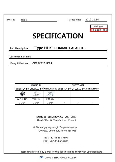
Messrs: <strong>Ropla</strong> Issued date : 2012.11.14<br />
SPECIFICATION<br />
Halogen<br />
Halogen Free<br />
Part Description :<br />
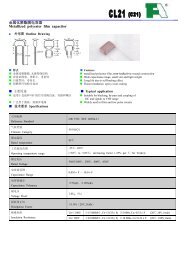
"Type HI-K" CERAMIC CAPACITOR<br />
Customer Part No :<br />
Dong il Part No :<br />
CK3FYB151<strong>KB</strong>S<br />
DONG IL<br />
WRITTEN by CHECKED by<br />
CUSTOMER<br />
APPROVED by WRITTEN by CHECKED by APPROVED by<br />
W.C.JUNG Y.H.LIM K.M.KIM<br />
11/14 11/14 11/14 / / /<br />
DONG IL ELECTRONICS CO., LTD.<br />
( Head Offics & Manufacture : Korea )<br />
6, Gaheunggongdan-gil, Gageum-myeon,<br />
Chungju, Chungbuk, Korea 380-921<br />
TEL : +82-43-855-7800<br />
FAX : +82-43-855-7803<br />
Please return to me by e-mail of this specification's cover with your signature<br />
DONG IL ELECTRONICS CO.,LTD
SPEC No.<br />
SPECIFICATION<br />
Rev. No. Page No.<br />
DIS-H-204 HIGH-DIELECTRIC HIGH VOLTAGE CERAMIC CAPACITOR 02 1<br />
Record of Revision<br />
Date Rev.No Description Issued by Checked by<br />
Remark<br />
2010.02.03 rev.01 Production specification review<br />
J.H Uhm B.S. Min<br />
2011.06.28 rev.02 2-1. Type Designation" Halogen Free "추가 S.H PARK H.S. CHI<br />
DONG IL ELECTRONICS CO.,LTD
SPEC No.<br />
SPECIFICATION<br />
Rev. No.<br />
Page No.<br />
DIS-H-204<br />
HIGH-DIELECTRIC HIGH VOLTAGE CERAMIC CAPACITOR<br />
02<br />
2<br />
1. SCOPE<br />
This specification is applied to high dielectric constant and<br />
temperature compensation ceramic capacitor.<br />
■ Features<br />
1. Small size and high capacitance<br />
2. Coated with flame-retardant epoxy resin<br />
(equivalent to UL94V-0 standard)<br />
3. Taping available for automatic insertion.<br />
2. Part Number for System<br />
2-1. Type Designation<br />
CK 3F YB 151 K B S P07 C04 F<br />
2-1-1 2-1-2 2-1-3 2-1-4 2-1-5 2-1-6 2-1-7 2-1-8 2-1-9 2-1-10<br />
For lead type straight short lead, lead tolerance is only ±0.3 mm available.<br />
2-1-1. Type<br />
CK : Epoxy coated High dielectric constant fixed ceramic capacitor.(class Ⅱ)<br />
2-1-2. Rating Voltage(DC)<br />
3A : 1KV, 3D : 2KV, 3F : 3KV, 3J : 6KV<br />
2-1-3. Temperature Characteristics<br />
T.C<br />
Temp. Char<br />
-25℃ ~ +85℃ +85℃ ~ +125℃<br />
R<br />
Within ±15 % Within +15% ~ -30 %<br />
B<br />
Within ±10 %<br />
E Within +22% ~ -56 %<br />
F Within +30% ~ -80 %<br />
Pre-heatment : Capacitor should be stored at 125±3℃ for 1 hr.,<br />
then placed at r<strong>oo</strong>m condition for 24 ±2 hrs.<br />
2-1-4. Nominal Capacitance<br />
The nominal capacitance value in pF is expressed by three digit number.<br />
The first two digits denote significant figure ; the last digit denotes the mulitiplier<br />
of 10 in pF of zero to follow. Ex) In case of 151 : 15 x 10 1 = 150pF<br />
DONG IL ELECTRONICS CO.,LTD
SPEC No.<br />
SPECIFICATION<br />
Rev. No.<br />
DIS-H-204 HIGH-DIELECTRIC HIGH VOLTAGE CERAMIC CAPACITOR 02<br />
Page No.<br />
3<br />
2-1-5. Capacitance Tolerance.<br />
K : ±10% M : ±20% P :-0 ~ +100% Z : +80~-20%<br />
2-1-6. Packing Style<br />
B<br />
F<br />
Bulk Type<br />
Taping Type "Flat Pack"<br />
2-1-7. Lead Variation<br />
K<br />
Kink Type or Vertical Type<br />
S<br />
Straight Type<br />
2-1-8. Lead <strong>Sp</strong>acing (F)<br />
Not mentioned 5.0 ( -02/+0.8 )<br />
P07 7.5 ± 1.0<br />
P10 10.0 ± 1.0<br />
2-1-9. Lead Cutting Length<br />
Lead Type Code Length (L)<br />
straight<br />
out kink<br />
vertical<br />
ㄱ Forming<br />
* Straight Long Type : 20 ± 1.0<br />
C03 2.8 ± 0.3<br />
C04 3.2 ± 0.3<br />
C07 6.3 ± 0.5<br />
C10 10.0 ± 0.3<br />
C04 LEFT : 2.9+0.6 / RIGHT : 4.9+0.6<br />
C05 LEFT : 4.7+0.6 / RIGHT : 6.7+0.6<br />
C07 7.0 ± 0.3<br />
2-1-10. Lead "ㄱ" Forming<br />
F<br />
Straight "ㄱ" Forming<br />
DONG IL ELECTRONICS CO.,LTD
SPEC No.<br />
SPECIFICATION<br />
Rev. No.<br />
DIS-H-204 HIGH-DIELECTRIC HIGH VOLTAGE CERAMIC CAPACITOR 02<br />
Page No.<br />
4<br />
3. Parts Numbering<br />
Part Number<br />
Temp<br />
Char<br />
R<br />
Capacitance<br />
(pF)<br />
CK3AYR471K**** R<br />
470<br />
CK3AYR681K****<br />
CK3AYR102K****<br />
CK3AYR222K****<br />
CK3AYR332K****<br />
R<br />
R<br />
R<br />
680<br />
Tolerance<br />
(%)<br />
±10<br />
D (max)<br />
CK3AYR101K**** R 100 ±10 6.0<br />
2200 ±10 13.0<br />
Dimensions(mm)<br />
T (max)<br />
CK3AYR221K**** R 220 ±10 6.0 4.5<br />
4.5<br />
6.0 4.5<br />
±10 7.0 4.5<br />
1000 ±10 8.0 4.5<br />
4.5<br />
3300 ±10 16.0 4.5<br />
Lead<br />
<strong>Sp</strong>acing(F)<br />
5.0<br />
( -02/+0.8 )<br />
5.0<br />
( -02/+0.8 )<br />
5.0<br />
( -02/+0.8 )<br />
5.0<br />
( -02/+0.8 )<br />
5.0<br />
( -02/+0.8 )<br />
5.0<br />
( -02/+0.8 )<br />
7.5±1<br />
CK3AYR472K****<br />
R<br />
4700 ±10 22.0<br />
4.5 10.0±1<br />
CK3DYR101K****<br />
CK3DYR221K****<br />
CK3DYR561K****<br />
R<br />
R<br />
R<br />
100 ±10 8.0<br />
220 ±10 8.0<br />
560 ±10 9.0<br />
5.0<br />
5.0<br />
5.0<br />
5.0<br />
( -02/+0.8 )<br />
5.0<br />
( -02/+0.8 )<br />
5.0<br />
( -02/+0.8 )<br />
CK3DYR102K****<br />
R<br />
1000 ±10 10.0 5.0<br />
7.5±1<br />
5.0<br />
CK3AYB101K****<br />
B<br />
100 ±10 6.0 4.5<br />
( -02/+0.8 )<br />
CK3AYB221K****<br />
B<br />
220 ±10 6.0 4.5<br />
5.0<br />
( -02/+0.8 )<br />
CK3AYB102K**** B 1000 ±10 7.0 4.5<br />
5.0<br />
( -02/+0.8 )<br />
CK3AYB152K****<br />
B<br />
1500 ±10 9.0 4.5<br />
5.0<br />
( -02/+0.8 )<br />
CK3AYB222K**** B 2200 ±10 9.0 4.5<br />
5.0<br />
( -02/+0.8 )<br />
5.0<br />
CK3AYB332K**** B 3300 ±10 13.0 4.5<br />
( -02/+0.8 )<br />
CK3AYB472K**** B 4700 ±10 16.0 4.5 7.5±1<br />
CK3DYB101K**** B 100 ±10 8.0 5.0<br />
5.0<br />
( -02/+0.8 )<br />
CK3DYB221K**** B 220 ±10 8.0 5.0<br />
5.0<br />
( -02/+0.8 )<br />
CK3DYB102K**** B 1000 ±10 9.0 5.0<br />
5.0<br />
( -02/+0.8 )<br />
CK3DYB152K**** B 1500 ±10 10.0 5.0 7.5±1<br />
CK3DYB222K**** B 2200 ±10 11.0 5.0<br />
7.5±1<br />
CK3DYB472K**** B 4700 ±10 16.0 5.0 10.0±1<br />
DONG IL ELECTRONICS CO.,LTD
SPEC No.<br />
SPECIFICATION<br />
Rev. No. Page No.<br />
DIS-H-204 HIGH-DIELECTRIC HIGH VOLTAGE CERAMIC CAPACITOR 02<br />
5<br />
Part Number<br />
Temp Capacitance Tolerance<br />
Dimensions(mm)<br />
Char<br />
(pF) (%)<br />
Lead<br />
D (max) T (max)<br />
<strong>Sp</strong>acing(F)<br />
CK3FYB101K****<br />
B<br />
100 ±10 7.0 5.5<br />
5.0<br />
( -02/+0.8 )<br />
CK3FYB151K**** B 150 ±10 7.0 5.5<br />
5.0<br />
( -02/+0.8 )<br />
CK3FYB561K****<br />
B<br />
560 ±10 8.0 5.5<br />
5.0<br />
( -02/+0.8 )<br />
CK3FYB821K**** B 820 ±10 9.0 5.5 7.5±1<br />
CK3FYB102K**** B 1000 ±10 10.0<br />
5.5<br />
7.5±1<br />
CK3FYB152K**** B 1500 ±10 12.0<br />
5.5 10.0±1<br />
CK3FYB222K****<br />
B<br />
2200 ±10 13.0 5.5<br />
10.0±1<br />
CK3JYB471K****<br />
B 470 ±10 8.0 6.0<br />
7.5±1<br />
CK3JYB681K**** B 680 ±10 9.0 6.0<br />
CK3JYB102K**** B 1000 ±10 10.0 6.0<br />
7.5±1<br />
10.0±1<br />
CK3AYE102P****<br />
E 1000 -0 ~ +100 6.0 4.5<br />
5.0<br />
( -02/+0.8 )<br />
CK3AYE222P****<br />
E 2200 -0 ~ +100 7.0 4.5<br />
5.0<br />
( -02/+0.8 )<br />
CK3AYE472P****<br />
CK3AYE103P****<br />
E<br />
E<br />
4700<br />
10000<br />
-0 ~ +100<br />
-0 ~ +100<br />
9.0<br />
16.0<br />
4.5<br />
4.5<br />
5.0<br />
( -02/+0.8 )<br />
7.5±1<br />
CK3DYE102P****<br />
E<br />
1000<br />
-0 ~ +100<br />
8.0<br />
5.0<br />
5.0<br />
( -02/+0.8 )<br />
CK3DYE222P****<br />
E<br />
2200 -0 ~ +100<br />
9.0<br />
5.0<br />
7.5±1<br />
CK3FYE472P****<br />
E<br />
4700 -0 ~ +100 12.0 5.5<br />
10.0±1<br />
CK3AYF103Z**** F 10000 -20 ~ + 80 9.0 4.5<br />
5.0<br />
( -02/+0.8 )<br />
CK3DYF103Z**** F 10000 -20 ~ + 80 16.0 5.0 10.0±1<br />
* DONG IL part number might have additional code digits due to lead type and speicial settings<br />
DONG IL ELECTRONICS CO.,LTD
SPEC No.<br />
SPECIFICATION<br />
Rev. No.<br />
DIS-H-204 HIGH-DIELECTRIC HIGH VOLTAGE CERAMIC CAPACITOR 02<br />
Page No.<br />
6<br />
4. Taping and Bulk Type<br />
4-1. Taping Type<br />
1 12.7 Pitch Straight<br />
2 12.7 Pitch KINK<br />
3 15.0 Pitch Straight<br />
4 15.0 Pitch KINK<br />
ITEM<br />
Bady Diameter<br />
Pitch of component<br />
Pitch of <strong>Sp</strong>rocket Hole<br />
Lead spacing<br />
Length from hole center to component center<br />
Length from hole center to lead<br />
Deviation along tape, left or right<br />
Carrier tape width<br />
Position of sproket hole<br />
Lead distance between and bottom planes<br />
Protrusion length<br />
Diameter of sprocket hole<br />
Lead diameter<br />
Total tape thickness<br />
Total thickness,tape and lead wire<br />
Body thickness<br />
Portion to cut in case of defect<br />
Hold down tape width<br />
Hold down tape position<br />
CODE<br />
Dimensions(mm)<br />
1 2 3 4<br />
D 5.0
SPEC No.<br />
SPECIFICATION<br />
Rev. No.<br />
Page No.<br />
DIS-H-204<br />
HIGH-DIELECTRIC HIGH VOLTAGE CERAMIC CAPACITOR<br />
02<br />
7<br />
4-2. Bulk Type<br />
straight<br />
out Kink<br />
5. Standard Marking<br />
MARKING ITEMS<br />
1. TEMPERATURE CHARACTERISTICS<br />
2. NOMINAL CAPACITANCE<br />
3. TOLERANCE<br />
4. RATED VOLTAGE<br />
EXAMPLE<br />
1<br />
B<br />
2 151K<br />
3<br />
4 3KV<br />
6. Packing <strong>Sp</strong>ecification<br />
6.1. Taping Type<br />
Type PITCH<br />
12.7<br />
DC<br />
15.0<br />
TAPING<br />
IN BOX<br />
OUT BOX<br />
2,000 12,000<br />
1,000 6,000<br />
6-2. Bulk Type<br />
Dia (DΦ)<br />
Straight Long type<br />
Forming Cutting type<br />
Vinyl In box Vinyl In box<br />
6Φ 1,000 5,000 1,000 6,000<br />
7Φ~8Φ 1,000 4,000 1,000 6,000<br />
9Φ~10Φ 500 2,000 1,000 4,000<br />
14Φ 500 2,000 500 2,000<br />
DONG IL ELECTRONICS CO.,LTD
SPEC No.<br />
SPECIFICATION<br />
Rev. No.<br />
Page No.<br />
DIS-H-204 HIGH-DIELECTRIC HIGH VOLTAGE CERAMIC CAPACITOR 02<br />
8<br />
7. <strong>Sp</strong>ecification and Reliability Test Method<br />
7-1 Capacitance<br />
Capacitance shall be within specified limits when measured at a<br />
Voltage of 1Vrms and a frequency of 1KHz at 20±3℃.<br />
7-2 Dissipation Factor tanδ(%)<br />
The dissipation factor shall be within limits when measured at a<br />
Voltage 1Vrms and a frequency of 1KHz at 20±3℃.<br />
table 1)<br />
Temp.Char. R B<br />
E F<br />
tanδ(%) 0.2% max 2.5% max 2.5% max 5.0% max<br />
7-3 Withstand Voltage (between Terminals)<br />
Capacitors shall be withst<strong>oo</strong>d the test voltage specified in the<br />
individual specification without damage or breakdown when measured<br />
60Sec after application twice of rated voltage.<br />
7-4 Withstand Voltage (between terminal and body)<br />
Capacitors shall not be damage when rated voltege as below condition<br />
Applied both connected leads and body.<br />
60Sec after appilcation twice of rated voltage.<br />
7-5 Reliability Test<br />
7-5-1 Temperature Charecteristics<br />
The rate of capacitance variation shall be satisfied table 2) when<br />
Measured the capacitance within the temperature range of table 2).<br />
(Standard temperature : 20±3℃)<br />
table 2)<br />
T.C<br />
Temp. Char<br />
RATE OF CAPACITANCE VARIATION<br />
R<br />
B<br />
-25℃∼+85℃ ±15 %<br />
+85℃ ~ +125℃ +15 ~ -30 %<br />
-25℃∼+85℃ ±10%<br />
E -25℃∼+85℃ +22%∼-56%<br />
F<br />
-25℃∼+85℃<br />
+30%∼-80%<br />
DONG IL ELECTRONICS CO.,LTD
SPEC No.<br />
SPECIFICATION<br />
Rev. No.<br />
Page No.<br />
DIS-H-204 HIGH-DIELECTRIC HIGH VOLTAGE CERAMIC CAPACITOR 02<br />
9<br />
7-5-2 Humidity Test<br />
Shall be subjected to a temperature of 40±3℃ and<br />
Relative humidity between 90∼95% for 500 (0∼+24) hours and the<br />
Maintaided at normal temperature and humidity for a period of 4~24<br />
hours the following table 3) shall be satisfied.<br />
table 3)<br />
TEMP. CHAR<br />
R<br />
B<br />
E<br />
F<br />
Change Rate<br />
±10%<br />
±10% ±20%<br />
±30%<br />
Dissipation Factor (Tanδ%)<br />
Insulation Resistance<br />
0.6%MAX 5% MAX 5% MAX 7.5% MAX<br />
3000MΩ MIN<br />
7-5-3 Humidity Loading Test<br />
Capacitors shall be subjested to a temperature of 40±3℃ and apply 100% of<br />
DC rated voltege, relative humidity between 90~95% after application rated<br />
voltege and limiting the charging and discharging current to 50mA for<br />
500Hours and then tested within 4~24 hours the following table 4)<br />
shall be satisfied.<br />
table 4)<br />
TEMP. CHAR<br />
R B E<br />
F<br />
Change Rate<br />
Dissipation Factor(Tanδ%)<br />
Insulation Resistance<br />
±10% ±10% ±20% ±30%<br />
0.6%MAX 5% MAX 5% MAX 7.5% MAX<br />
3000MΩ MIN<br />
DONG IL ELECTRONICS CO.,LTD
SPEC No.<br />
SPECIFICATION<br />
Rev. No.<br />
DIS-H-204 HIGH-DIELECTRIC HIGH VOLTAGE CERAMIC CAPACITOR 02<br />
Page No.<br />
10<br />
7-5-4 High Temperature Loading Test<br />
Capacitors shall be subjected to a temperature of 85±3℃ and apply 200% of<br />
DC rated voltage(application twice of rated voltage) and limit the charging<br />
and discharging current to 50mA for 1000Hours and then maintained a<br />
normal temperature and humidity for a period of 4~24 hours the<br />
following table 5) shall be satisfied.<br />
table 5)<br />
TEMP. CHAR R B E F<br />
Change Rate ±10% ±10% ±20% ±30%<br />
Dissipation Factor(Tanδ%)<br />
Insulation Resistance<br />
0.6%MAX 4% MAX 4% MAX 7.5% MAX<br />
3000MΩ MIN<br />
7-5-5 Thermal Shock Test<br />
-45℃(30min)~+125℃(30min), It is 100 Cycle operation to → one Cycle (One hour)<br />
measure it after 12 to 24 hour, the following measurement satisfies table 6).<br />
table 6)<br />
TEMP. CHAR<br />
R B E F<br />
Change Rate ±10% ±10% ±20% ±30%<br />
Dissipation Factor(Tanδ%) 0.6%MAX 4% MAX 4% MAX 7.5% MAX<br />
Insulation Resistance<br />
3000MΩ MIN<br />
7-5-6 Discharge Test (Ⅰ)<br />
Capacitors shall comply with two following requirements, after with<br />
standing 50 discharges from a 1000pF capacitor. Charged to potential<br />
of 10kv DC, with an interval of 5 seconds between successive discharge,<br />
as shown below.<br />
Ct : Capacitor under test<br />
Cd: 0.001μF<br />
R1: 1000Ω<br />
R2: 100MΩ<br />
Visual examination . . . . No mechanical damage<br />
Dielectric withstanding voltage . . . The voltage as satisfied in<br />
the individual specification<br />
DONG IL ELECTRONICS CO.,LTD
SPEC No.<br />
SPECIFICATION<br />
Rev. No.<br />
Page No.<br />
DIS-H-204 HIGH-DIELECTRIC HIGH VOLTAGE CERAMIC CAPACITOR 02<br />
11<br />
7-5-7 Discharge Test (II)<br />
Capacitors shall comply with the following requirements, after with<br />
standing four discharges from a dump capacitor charged to a<br />
voltage value that when dischaged places a potenstial of 5 Kv across<br />
the capacitor test, with an interval of 5 seconds between<br />
successive discharges, as shown in the circuit below.<br />
Vdc : Variable direct-current voltage source<br />
L : Choke coil of approximately 3mH and 0.03Ω<br />
S : High-voltage switch<br />
Cd : Dump capacitor<br />
Ct : Capacitor under test<br />
The direct current supply is to DE adjusted to potential in<br />
accordance with the following<br />
CAPACITANCE VALUE OF CT 0∼0.005μF 0.0051∼0.05μF<br />
CAPACITANCE VALUE OF CD 0.005μF 0.05μF<br />
DISSIPATION FACTOR OF CD 0.5 % max 0.5 % max<br />
The cheesecloth around capacitors shall not<br />
APPEARANCE<br />
glow of flame<br />
5000 ( Cd + Ct )<br />
VDC = ───────── ( V )<br />
Cd<br />
CD : dump capacitor 0.005μF(CT≥0.05μF) OR 0.05μF(0.005μF
SPEC No.<br />
SPECIFICATION<br />
Rev. No.<br />
DIS-H-204 HIGH-DIELECTRIC HIGH VOLTAGE CERAMIC CAPACITOR 02<br />
Page No.<br />
12<br />
8. 9. Capacitor structure & Material<br />
8-1 Capacitor structure<br />
No.<br />
1<br />
2<br />
3<br />
4<br />
5<br />
Material<br />
Dieletric Powder<br />
Ag Plate<br />
Solder (Lead Free)<br />
Epoxy Resin<br />
Lead Wire<br />
Substance<br />
BaTiO3, Tio2<br />
Ag<br />
Sn, Ag, Cu<br />
Pel-Powder<br />
CP (Steel-Wire)<br />
* Lead Wire Plating thickness : 3μm min (material: Tin)<br />
8-2. Lead wire<br />
No. Material<br />
1 Steel-wire (Fe)<br />
2 Copper (Cu)<br />
3 TIN (Sn)<br />
CP Lead Wire<br />
8-3. Pb free showing 8-4. Halogen free showing<br />
* The Mark is showing to all label<br />
DONG IL ELECTRONICS CO.,LTD