Body Builders Layout Book - Ford Fleet
Body Builders Layout Book - Ford Fleet
Body Builders Layout Book - Ford Fleet

Create successful ePaper yourself
Turn your PDF publications into a flip-book with our unique Google optimized e-Paper software.
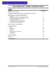
1<br />
DESIGN<br />
DESIGN RECOMMENDATIONS Page<br />
Fuel System 2-4<br />
Electrical System<br />
Cooling System / Climate Control System 5-6<br />
Exhaust System / <strong>Ford</strong> <strong>Body</strong> Components<br />
Wheels & Tires / TPMS 8<br />
Suspension & Steering / Engine<br />
Driveline / Transmission / Frame / Jack 10<br />
Ambulance <strong>Builders</strong> Guidelines<br />
New Vehicle Storage Guidelines 12<br />
www.fleet.ford.com/truckbbas<br />
<strong>Body</strong> <strong>Builders</strong> <strong>Layout</strong> <strong>Book</strong><br />
DESIGN RECOMMENDATIONS<br />
INDEX<br />
4<br />
7<br />
9<br />
11<br />
2012<br />
MODEL YEAR
2<br />
DESIGN<br />
FUEL SYSTEM<br />
WARNING:<br />
BEFORE OPENING THE FUEL SYSTEM ON VEHICLES WITH<br />
EFI ENGINES, RELIEVE FUEL PRESSURE BY FOLLOWING<br />
THE INSTRUCTIONS IN THE FORD TRUCK SHOP MANUAL<br />
FOR THE APPROPRIATE MODEL AND MODEL YEAR.<br />
THE EVAPORATIVE EMISSION SYSTEM CONTAINS FUEL<br />
VAPOR AND CONDENSED FUEL VAPOR. ALTHOUGH NOT<br />
PRESENT IN LARGE QUANTITIES, IT STILL PRESENTS THE<br />
DANGER OF EXPLOSION OR FIRE.<br />
WHEN WELDING NEAR FUEL SYSTEM COMPONENTS, ALL<br />
METALIC COMPONENTS SHOULD BE ADEQUATELY<br />
SHIELDED AND PROTECTED FROM HEAT OR WELD<br />
SPLATTER. ALL NON-METALLIC COMPONENTS SHOULD BE<br />
REMOVED.<br />
REMOVAL OR REINSTALLATION OF ANY FORD FUEL<br />
SYSTEM COMPONENT SHOULD BE PERFORMED TO THE<br />
SPECIFICATIONS AND INSTRUCTIONS FOUND IN THE FORD<br />
TRUCK SHOP MANUAL FOR THE APPROPRIATE MODEL<br />
AND MODEL YEAR. (EXCEPT FOR E-SERIES VAN AFT-OF-<br />
AXLE TANK INSTALLATIONS, SEE THE FOLLOWING NOTE).<br />
E-SERIES VAN AFT-OF-AXLE FUEL TANK<br />
A Fuel System Modification Kit is available for some E-Series<br />
products for removing the midship fuel tank and adding an<br />
aft-of-axle fuel tank. This kit is distributed by:<br />
Transfer Flow Inc.<br />
1444 Fortress Street<br />
Chino, California 95973<br />
Phone: (800) 442-0056<br />
Fax: (530) 892-0382<br />
NOTE: The modifier is responsible for determining if the<br />
vehicle as modified with this kit meets applicable<br />
safety & emission regulations and is properly<br />
certified.<br />
INFORMATION<br />
The following recommendations are intended to assist in<br />
the design and completion of the fuel system capable of<br />
meeting the requirements of F/CMVSS 301. These<br />
recommendations are based on testing and analysis<br />
performed by <strong>Ford</strong> Motor Company.<br />
Since completed vehicles may take many forms, this list<br />
of recommendations cannot cover all possibilities. Strict<br />
adherence to these suggestions will not ensure that the<br />
completed vehicle will comply with F/CMVSS 301. The<br />
responsibility for determining compliance to F/CMVSS<br />
301 regulations is that of the final stage manufacturer.<br />
www.fleet.ford.com/truckbbas<br />
Accordingly, <strong>Ford</strong> Motor Company makes no<br />
representations as to the appropriateness of any<br />
particular recommendation in its specific application to a<br />
particular design or act of intermediate or final stage<br />
manufacture.<br />
To verify compliance with F/CMVSS 301, testing of<br />
representative vehicles to applicable F/CMVSS 301<br />
procedures may be necessary. Questions regarding<br />
compliance with F/CMVSS regulations should be<br />
directed to your legal counsel, the National Highway<br />
Traffic Safety Administration, or Transport Canada.<br />
Any alteration or modification of a vehicle’s fuel or<br />
evaporative system may affect the vehicle’s compliance<br />
with applicable federal and state emission laws,<br />
including on-board diagnostics (OBDII) and evaporative<br />
emissions requirements, and may also effect vehicle<br />
performance (driveability, idle quality, etc.). Vehicle<br />
modifiers are responsible for ensuring that a vehicle, as<br />
modified, complies with all applicable emissions<br />
regulations and for obtaining any necessary federal or<br />
state approval or certification relating to vehicle<br />
modification or sale of add-on or auxiliary parts.<br />
A. NEW FUEL TANKS<br />
1. The fuel tank should be designed with as few<br />
openings and connections as possible. Openings<br />
and connections generally should be located on the<br />
upper surface of the fuel tank.<br />
2. Fuel tanks should be fitted with an evaporation<br />
control valve having the means to close if the<br />
vehicle is rotated about a longitudinal axis pursuant<br />
to F/CMVSS 301.<br />
3. The tank should be of simple configuration<br />
minimizing sharp surface transitions and<br />
protrusions which may be required for attachment<br />
or function.<br />
4. The tank should be strong enough to withstand<br />
instantaneous internal pressure imposed in the<br />
event of crash situations.<br />
5. Hoses connected to the tank should be sufficiently<br />
flexible to permit small movements of the tank<br />
relative to fixed mounting surfaces, without rupture<br />
or disconnection of such hoses in the event of crash<br />
situations.<br />
6. Emission regulations may require an OBDII fuel<br />
tank pressure sensor for the evaporative system.<br />
Any new fuel tank must be tested and comply with<br />
all emission regulations, including evaporative<br />
emissions.<br />
7. Package new tank away from heat sources such as<br />
exhaust.<br />
<strong>Body</strong> <strong>Builders</strong> <strong>Layout</strong> <strong>Book</strong><br />
DESIGN RECOMMENDATIONS<br />
FUEL SYSTEM<br />
B. NEW FUEL TANK RETENTION SYSTEMS<br />
1. The retention system should attach the fuel tank to<br />
the frame, between the frame rails, and below the<br />
body of the vehicle with sufficient clearance for<br />
normal body to frame movement under loaded<br />
conditions.<br />
2. A retention system should restrict fuel tank<br />
movement in all possible directions to prevent<br />
contact or rupture with rigid or sharp objects, and<br />
the disconnection of fuel system tubes and hoses<br />
under crash conditions. Retention straps should<br />
avoid sharp edges and tank supports should be<br />
designed with fuel tank compatible surfaces and<br />
edges to the fuel tank.<br />
3. System fasteners and attachments should be<br />
designed to retain the tank during deflections<br />
incurred in crash situations.<br />
C. FUEL FILL SYSTEM<br />
1. Fill system should be sufficiently flexible to prevent<br />
possible rupture or disconnection resulting from<br />
movement of the fuel tank relative to frame during<br />
crash situations. Use the original pickup truck filler if<br />
the fill location is similar to the original pickup truck<br />
location.<br />
2. Any appliance or hardware attachments to the body<br />
in the area of a fuel system component should be<br />
designed, positioned, and secured so as not to<br />
impact any fuel system component during crash<br />
situations.<br />
3. The fuel filler opening area of the body should<br />
provide adequate sealing from the vehicle interior<br />
because holes or cracks in this area may allow fuel<br />
vapors to enter the vehicle interior. Openings<br />
should be sealed with a product which is fuel<br />
resistant. See Figure A on this page.<br />
4. The metal outer end of the fuel fill neck tube<br />
provided by <strong>Ford</strong> must be properly grounded to the<br />
chassis to dissipate any electrostatic charge that<br />
may be produced and so reduce the possibility of a<br />
spark during fueling. A fill neck support made of<br />
metal would provide a ground path if directly<br />
mounted on the chassis. If the filler neck support is<br />
made of plastic or other non-metallic material, a<br />
ground strap or wire must connect the metal end of<br />
the fuel filler neck and a metal chassis component.<br />
2012<br />
MODEL YEAR<br />
FIGURE A – BODY MOUNTED FUEL FILLER OPENINGS<br />
5. Fill openings should be recessed, and caps, when<br />
installed, should be inside the normal body plane.<br />
6. Whenever possible, the fill system should pass<br />
under the body rather than through it. Where<br />
passing through floors and sides, the fill system<br />
should be shielded and have adequate clearance to<br />
surrounding structure. Fuel Filler and Vent Hoses<br />
should maintain a minimum of one inch clearance<br />
to body and surrounding chassis components,<br />
except where the hoses and protective sleeve<br />
material pass through the designed frame opening.<br />
7. Be sure that the fuel tank filler cap is the correct<br />
<strong>Ford</strong> designated part. Provide adequate hand<br />
clearance for cap installation and correct sealing of<br />
the cap to filler pipe.<br />
8. The recommended horizontal and vertical locations<br />
for the fuel tank filler pipe are shown in the E-<br />
Series and Super Duty F-Series sections of this<br />
book.<br />
Vehicle Engine Fuel Tank Fuel Fill Kit P/N<br />
F-Super Duty<br />
Chassis Cab<br />
Wide Frame<br />
Pickup<br />
Other parts that can be ordered/purchased separately:<br />
PART DESCRIPTION<br />
Support (unskirted body)<br />
Label – Unleaded Fuel<br />
Label – Diesel Fuel<br />
ISOLATOR-<br />
FILL NECK<br />
Diesel<br />
Gas<br />
Diesel<br />
Gas<br />
BODY<br />
SIDE<br />
PANEL<br />
FUEL<br />
FILLER<br />
FRAME<br />
Midship 8C3Z-9B149-AF<br />
Aft of axle 8C3Z-9B149-CF<br />
Midship 8C3Z-9B149-BD<br />
Aft of axle 8C3Z-9B149-DD<br />
Box delete 8C3Z-9B149-EF<br />
Box removed 9C3Z-9B149-B<br />
Box delete (slow fill fix) 8C3Z-9B149-L<br />
Box removed 8C3Z-9B149-J<br />
E-Series Cutaway<br />
E250<br />
E350/450/<br />
School Bus<br />
FFV<br />
Gas<br />
Diesel<br />
Midship<br />
Aft of axle<br />
AC2Z-9B149-A<br />
9C2Z-9B149-A<br />
9C2Z-9B149-C<br />
9C2Z-9B149-B<br />
SERVICE P/N<br />
E0TZ-9040-A<br />
D702-9A095-A<br />
E432-9A095-A<br />
ISOLATOR-<br />
FILL NECK<br />
LINOLEUM/CARPET<br />
FLOORING<br />
(Cont'd next page)
3<br />
DESIGN<br />
C. FUEL FILL SYSTEM (CONT’D)<br />
9. When installing accessories or equipment, avoid<br />
exposure of fuel and vapor hoses to surfaces with<br />
sharp edges (see Figure B on this page) or high<br />
temperature surfaces (near hot exhaust or coolant).<br />
Also avoid installations which result in the exposure<br />
of these lines to road debris or undercoating.<br />
10. Install or route fuel tank filler hoses and filler vent<br />
hoses as follows:<br />
a. Avoid sags below the horizontal which allow fuel<br />
puddling (i.e., avoid sink traps). See Sink Traps<br />
in Figure B. Fuel trapped in low spots can be<br />
expelled when the cap is removed, even if the<br />
tank is nearly empty.<br />
b. Avoid pinches or kinks, as they restrict fuel filling<br />
or venting. Hose length may require adjusting<br />
depending on second unit body width. See<br />
Kinked Fuel Fill System, Figure B.<br />
c. Do not place adjacent hardware such that it may<br />
cut or otherwise damage the filler neck and vent<br />
hoses and cause fuel or vapor leakage (i.e.,<br />
avoid unfriendly surfaces) see Hostile Surfaces,<br />
Figure B.<br />
d. Keep the flow of fuel continuously downward<br />
from the inlet of the fuel filler pipe all the way to<br />
the tank.<br />
e. The filler hose and vent hose must be clear of<br />
moving suspension components so as to<br />
prevent abrasion which can result in fuel<br />
leakage. They should maintain a minimum of 1<br />
inch clearance to body and surrounding chassis<br />
components, except where the hoses and<br />
protective sleeve material pass through the<br />
designed frame opening.<br />
f. Be certain that all clamps are secure and<br />
properly located.<br />
g. The fuel filler and filler vent hoses should not<br />
contain fittings or connections other than those<br />
incorporated in the original design, nor should<br />
they be interconnected with each other in any<br />
way.<br />
h. <strong>Ford</strong> released parts should be used.<br />
www.fleet.ford.com/truckbbas<br />
FUEL FILLER<br />
BB0286<br />
AVOID “SINK TRAPS”<br />
IN THE FUEL FILLER HOSE<br />
TRAPPED<br />
FUEL<br />
SINK TRAPS<br />
AVOID FUEL FILLER<br />
KINKED DUE TO<br />
IMPROPER ROUTING<br />
FRAME<br />
KINKED FUEL FILL SYSTEM<br />
<strong>Body</strong> <strong>Builders</strong> <strong>Layout</strong> <strong>Book</strong><br />
DESIGN RECOMMENDATIONS<br />
FUEL SYSTEM (Cont'd)<br />
AVOID JAGGED<br />
EDGE OPENING<br />
FILLER VENT<br />
HOSTILE SURFACES<br />
PROTECT FROM<br />
SHARP EDGE<br />
AVOID FILLER VENT<br />
KINKED DUE TO<br />
IMPROPER ROUTING<br />
FIGURE B – FUEL FILL SYSTEM INSTALLATION<br />
CONDITIONS TO BE AVOIDED<br />
FRAME<br />
SPACER<br />
FRAME<br />
D. FUEL TUBES, HOSES AND PUMPS<br />
1. Do not reroute or change the attachment of fuel<br />
lines or fuel vapor hoses. Doing so may alter the<br />
vehicle’s ability to comply with F/CMVSS 301, Fuel<br />
System Integrity, and may adversely affect vehicle<br />
performance by increasing the amount of heat<br />
absorbed by the fuel system or by restricting its<br />
venting.<br />
2. Tubes and hoses should be routed away from and<br />
not attached to members that will move or deform<br />
during crash situations.<br />
3. Tubes and hoses must be sufficiently flexible to<br />
avoid rupture or disconnection resulting from<br />
movement of the engine relative to the frame during<br />
crash situations.<br />
4. Tubes and hoses should be routed away from hot<br />
regions and sharp objects and should be retained<br />
adequately to prevent movement into such regions<br />
or against such objects.<br />
5. Do not add fuel or vapor line flow restrictors as they<br />
can cause engine fuel starvation or abnormally high<br />
fuel tank pressures.<br />
6. Do not install auxiliary fuel pumps. This could<br />
cause the engine to run rich, producing additional<br />
exhaust heat.<br />
7. The special removal tool shown in Figure D on the<br />
next page must be used to open push connectors<br />
installed on flexible fuel lines if the lines need to be<br />
disconnected. The appropriate tool is available from<br />
<strong>Ford</strong> Customer Service Division.<br />
8. The push connectors on flexible fuel lines, if<br />
disconnected, must be reconnected by snapping<br />
them back into position and installing the<br />
appropriate retainer as shown in Figure D on the<br />
next page.<br />
2012<br />
MODEL YEAR<br />
9. Avoid pinching or kinking of any fuel vapor hose.<br />
(See Figure C below).<br />
BODY SILL<br />
PINCHED FUEL HOSE TOP OF<br />
FUEL TANK<br />
FIGURE C - PINCHED FUEL VAPOR LINES<br />
10. Each of the fuel lines and fuel vapor hose retention<br />
clips provided by <strong>Ford</strong> must be used in original<br />
factory locations to prevent misplacement or<br />
movement of the lines.<br />
11. Be certain that the vent valves on top of the fuel<br />
tanks are seated and secure; do not dislodge or<br />
damage them when mounting the second unit body.<br />
If they are unseated, fuel leakage may occur. If<br />
damaged, the vapor vent system may not function,<br />
resulting in increased fuel tank pressure.<br />
12. If a fuel sender is removed for any reason, use a<br />
new gasket when it is reinstalled so as to prevent<br />
fuel leaks. Be certain the fuel sender is seated and<br />
secure on the top of each fuel tank. Do not step<br />
upon or place weight upon the sender during<br />
vehicle manufacture.<br />
13. Fuel filters installed in the fuel supply line must be<br />
of sufficient size to be nonrestrictive to fuel flow and<br />
placed so as to be protected from exposure to<br />
exhaust heat and physical damage. <strong>Ford</strong><br />
replacement fuel filters are recommended. Filters<br />
are not to be installed in the fuel return line.<br />
14. Temporary shipping fuel lines are not to be<br />
reused. They should be disposed of in an<br />
appropriate manner.<br />
15. Fuel system components which are disconnected<br />
during manufacturing should be capped or plugged<br />
promptly to prevent possible contamination.<br />
16. When welding near fuel system components, all<br />
metallic components must be adequately shielded<br />
and protected from heat or weld splatter. All<br />
nonmetallic components must be removed.<br />
(Cont'd next page)
4<br />
DESIGN<br />
E. FUEL SYSTEM ACCESS FOR AUXILIARY FUEL<br />
POWERED EQUIPMENT<br />
Precautions similar to those described in this Fuel<br />
System section should be taken in the design and<br />
positioning of a fuel system for auxiliary fuel-powered<br />
equipment. The auxiliary fuel-powered equipment<br />
should be securely mounted so as to withstand forces<br />
during crash situations.<br />
E-Series Super Duty Cutaway, Super Duty F-Series,<br />
and E-Series Super Duty Stripped Chassis aft-of-axle<br />
fuel tanks are equipped with an auxiliary fuel port in the<br />
fuel sender unit. The purpose is to provide a fuel supply<br />
for fuel powered accessories such as generator sets.<br />
E-Series van vehicles may have an optional auxiliary<br />
fuel port which is located on the midship fuel tank<br />
sender unit.<br />
Final stage manufacturers that utilize the auxiliary fuel<br />
port must install a check valve because of Onboard Fuel<br />
System Diagnostics (OBDII). The system may affect the<br />
vehicle’s compliance with applicable Federal/State<br />
emissions laws. Additional information is available in<br />
Bulletin Q-42. To obtain a copy, log on to<br />
www.fleet.ford.com/truckbbas and select from the list<br />
under the “Bulletins” tab.<br />
All auxiliary fuel ports have a safety cap which must<br />
remain in place until a fuel consuming accessory is<br />
installed.<br />
E-Series van vehicles equipped with the auxiliary fuel<br />
port have a braided jumper hose which provides access<br />
without removing the fuel tank. A cap removal tool is<br />
provided on the jumper line immediately behind the cap<br />
and must be removed and reversed before it can be<br />
used to remove the cap.<br />
A push connector fuel tank kit 9C24-9B210-AA,<br />
available from your local <strong>Ford</strong> dealer, will attach to the<br />
auxiliary fuel port and accept a 1/4” hose. The kit<br />
includes a 90 degree connector and a screw clamp.<br />
www.fleet.ford.com/truckbbas<br />
<strong>Body</strong> <strong>Builders</strong> <strong>Layout</strong> <strong>Book</strong><br />
DESIGN RECOMMENDATIONS<br />
FUEL SYSTEM (Cont'd) / ELECTRICAL SYSTEM<br />
Remaining Fuel Volume (Gallons) at Auxiliary Tube Shut-off Level<br />
Model<br />
35 Gal<br />
Fuel Tank Capacity<br />
40 Gal 55 Gal 80 Gal<br />
E-Series (Gasoline) 4.7 8.7 12.1 --<br />
E-Series (Diesel) 11.5 13 18 --<br />
SD F-Series (Gasoline) -- 11 -- --<br />
SD F-Series (Diesel) -- 11 -- --<br />
F-53 -- -- -- 10<br />
F-59 -- 11 -- 10<br />
RETAINER – FUEL TUBE<br />
PUSH CONNECTOR<br />
REMOVAL TOOL<br />
REMOVAL TOOL<br />
WARNING<br />
BEFORE OPENING THE FUEL SYSTEM ON VEHICLES<br />
WITH EFI ENGINES, RELIEVE FUEL PRESSURE BY<br />
FOLLOWING THE INSTRUCTIONS IN THE FORD SHOP<br />
MANUAL FOR THE APPROPRIATE MODEL AND MODEL YEAR.<br />
FIGURE D – FLEXIBLE FUEL LINE PUSH-CONNECT<br />
2012<br />
MODEL YEAR<br />
ELECTRICAL SYSTEM<br />
Refer to Bulletin Q-130, “General Electrical Practices”,<br />
available at www.fleet.ford.com/truckbbas under the<br />
“Bulletins” tab.
5<br />
DESIGN<br />
COOLING SYSTEM<br />
1. Equipment such as flashing lights and sirens, spare<br />
tires or any other accessories should not be<br />
installed in the grille area forward of the radiator or<br />
air cleaner air inlet. Doing so restricts proper air<br />
flow through the radiator and engine<br />
compartments. E-Series and Super Duty F-Series<br />
are illustrated in the figure below.<br />
2. For proper engine cooling, do not alter, change the<br />
locations of, or remove the original equipment fan,<br />
fan clutch, or shroud.<br />
3. Maintain a 50/50 mixture of ethylene glycol-based<br />
antifreeze-to-water ratio when adding or modifying<br />
the heater system or auxiliary heater system. A 60/<br />
40 antifreeze-to-water ratio may be necessary<br />
during winter months in very cold climates. For the<br />
remainder of the year, however, a 50/50 ratio<br />
should be maintained.<br />
4. Upper radiator hoses and heater hoses, which are<br />
added or replaces, should be EPDM-Kevlar<br />
composition. Lower radiator hoses should be<br />
EPDM-Rayon composition.<br />
E-SERIES<br />
SUPER DUTY<br />
www.fleet.ford.com/truckbbas<br />
<strong>Body</strong> <strong>Builders</strong> <strong>Layout</strong> <strong>Book</strong><br />
DESIGN RECOMMENDATIONS<br />
COOLING SYSTEM / CLIMATE CONTROL SYSTEM<br />
5. The radiator and fan shroud should not be used as<br />
structural members and additional components<br />
should not be attached.<br />
6. Revisions to the Front End Accessory Drive<br />
System may affect the cooling system/component<br />
performance and are not recommended.<br />
7. Do not alter or modify the automatic transmission<br />
cooling system.<br />
8. The minimum radiator grille opening (excluding all<br />
grille parts) for the E-Series Stripped Chassis, to<br />
provide optimum cooling for the engine, is 300 sq.<br />
in.<br />
9. Equipment, hazardous materials markers, or<br />
placards must not obstruct the airflow to the<br />
radiator or the air cleaner inlet on the E-Series<br />
Super Duty Stripped Chassis.<br />
10. The E-Series Super Duty Stripped Chassis engine<br />
compartment must be designed to eliminate any air<br />
circulation restriction that would affect the air<br />
induction or cooling systems. An engine<br />
compartment must provide adequate flow-through<br />
ventilation to prevent local air temperature from<br />
exceeding recommended maximums.<br />
ACCESSORIES SHOULD<br />
NOT BLOCK AIRFLOW<br />
IN SHADED AREAS<br />
KEEP THIS<br />
AREA CLEAR<br />
ENGINE COOLING RADIATOR<br />
AIR CONDITIONER CONDENSER<br />
F-SERIES<br />
SUPER DUTY<br />
CLIMATE CONTROL SYSTEM<br />
1. An Auxiliary Heater A/C Connector Prep Package<br />
can be either standard or optional on E-Series<br />
vehicles for connecting auxiliary climate control<br />
systems to the <strong>Ford</strong> system. The following items<br />
are important for the maximum efficiency of the<br />
combined systems:<br />
• The connector tubes are under the floor directly<br />
below the driver’s seat.<br />
• The heater supply tube is identified with a white<br />
paint dot and should be connected to the lowest<br />
connection port on the auxiliary heater core.<br />
• The A/C connector tubes have a 20 x 1.5-6g<br />
metric thread for high pressure and 24 x 2.0-6g<br />
metric thread for low pressure.<br />
• If the vehicle is equipped with the auxiliary<br />
heater-air conditioner, do not operate the front<br />
A/C system prior to the addition of an auxiliary<br />
system. The system oil could settle in the<br />
connector tubes and not provide lubrication to<br />
the compressor. See Bulletin Q-47. To obtain a<br />
copy, log on to www.fleet.ford.com/truckbbas<br />
and select from the “Bulletins” tab.<br />
•<br />
The <strong>Ford</strong> auxiliary blower switch requires an<br />
electric relay for high-speed blower operation; a<br />
relay is included in <strong>Ford</strong> factory-installed rear<br />
climate control systems.<br />
2. R134-a charge A/C systems must use PAG-type<br />
lubricating oil Motorcraft part number YN-12-D,<br />
<strong>Ford</strong> part number F2AZ-19577-AD and must meet<br />
<strong>Ford</strong> specification WSH-M1C231-B. Always use the<br />
same refrigerant and lubricating oil as originally<br />
equipped by <strong>Ford</strong>.<br />
3. Maintain a 4% suspended oil ratio in the A/C<br />
system for proper compressor lubrication.<br />
2012<br />
MODEL YEAR<br />
4. E-Series A/C and refrigerant oil system are built<br />
from the factory in the following configurations:<br />
GASOLINE<br />
DIESEL<br />
VEHICLE CONFIGURATION R-134a (oz) R-134a (lb) PAG Oil (oz)<br />
Front Only<br />
30 1.875<br />
8<br />
Front & Auxilary (Van) 54 3.375 16<br />
Front w/ Optional Prep<br />
Packages (Chassis Cab only)<br />
30 1.875 16<br />
Front Only<br />
36 2.25 7<br />
Front & Auxilary (Van) 54 3.375 11<br />
Front w/ Optional Prep<br />
Packages (Chassis Cab only)<br />
36 2.25 11<br />
A label stating the total refrigerant charge, type of<br />
refrigerant (R-134a) and type of compressor<br />
lubricant oil (PAG) used must be affixed in a<br />
conspicuous place in the engine compartment.<br />
(Cont'd next page)
6<br />
DESIGN<br />
CLIMATE CONTROL SYSTEM (Cont’d)<br />
5. The A/C compressor will cycle during the defrost<br />
mode. A refrigerant shut-off valve for the auxiliary<br />
system may impair compressor lubrication.<br />
6. R-134A charged A/C systems should use barrier<br />
type A/C hose. Barbed fittings and external<br />
clamping may not be compatible with this type of<br />
hose. Swaged, permanent fittings on this type of<br />
hose are recommended.<br />
7. NEVER ATTACH ANY COMPONENT TO THE<br />
TRANSMISSION FILLER AND DIPSTICK TUBE.<br />
8. Auxiliary heater and air conditioning systems hose<br />
routings must consider the following:<br />
• Dynamic engine roll or any system component<br />
which has an operating zone. Make sure there<br />
is adequate clearance (e.g., transmission<br />
downshift linkage, steering column shift<br />
linkage).<br />
• Do not route heater or A/C hoses directly over<br />
or near the exhaust system.<br />
• Do not route hoses by attaching to the engine.<br />
• Use only metallic “Y” and “T” type fittings or<br />
OEM approved materials.<br />
• Do not route hose in wheelhouse area.<br />
• Do not route by sharp edges or moving<br />
component parts. There must be shield<br />
protection from any potential abrasive source.<br />
• When routing in stone kickup area, lines should<br />
be protected by shields. Minimize use of<br />
concentric protective heater hose shields. Limit<br />
length of concentric hose shields to 305 mm [12<br />
in] maximum.<br />
• Where possible, encase added suction lines in<br />
insulating foam from connector location under<br />
body to the secondary evaporator.<br />
www.fleet.ford.com/truckbbas<br />
<strong>Body</strong> <strong>Builders</strong> <strong>Layout</strong> <strong>Book</strong><br />
DESIGN RECOMMENDATIONS<br />
COOLING SYSTEM / CLIMATE CONTROL SYSTEM (Cont'd)<br />
9. For additional information, refer to Bulletin Q-148,<br />
“Air Conditioning and Front End Accessory Drive<br />
(FEAD) Design Best Practices - E-Series and F-<br />
Series”, available at www.fleet.ford.com/truckbbas<br />
under the “Bulletins” tab.<br />
10. Front End Air Flow:<br />
• There should be nothing mounted in front of or<br />
behind the front end grille opening which could<br />
reduce the effective air flow to the cooling<br />
module.<br />
• Under no circumstances should there by any<br />
modifications to the fan shroud or stator.<br />
• Do not modify or remove any seals which are part<br />
of the cooling module. (i.e., body seals,<br />
condenser seal, radiator seals, snow shield)<br />
These shields are intended to prevent engine<br />
heat recirculation back through the A/C<br />
condenser.<br />
11. Chassis Cab vehicles ordered with the optional<br />
AUX A/C packages:<br />
• When attaching an aftermarket AUX A/C unit to an<br />
existing OEM front A/C system, the AUX A/C unit<br />
must use a Thermal Expansion Valve (TXV). A<br />
Clutch Cycling Orifice Tube (CCOT) cannot be<br />
used.<br />
12. Compressor discharge gas temperature should<br />
never exceed 130°C [266°F] under any driving or<br />
idle conditions.<br />
13. Do not alter or change the pulley size.<br />
14. If designing an independent refrigerant loop<br />
(second compressor, condenser, etc.) for an<br />
auxiliary A/C system on a chassis cab vehicle, DO<br />
NOT order either of the E-Series Auxiliary Heater/<br />
A/C Connector prep packages.<br />
15. If adding auxiliary A/C to an F-Series system, no<br />
prep packages are available. Tap into the system<br />
using custom lines that obtain the liquid between<br />
the receiver drier and front TXV, and return the<br />
suction line between the front TXV and the<br />
compressor. The secondary evaporator must use a<br />
TXV.<br />
2012<br />
MODEL YEAR<br />
E-SERIES OPTIONAL A/C PREP PACKAGES<br />
1. The A/C Prep Package (available on the stripped<br />
chassis only) consists of a compressor and<br />
condenser only with computer logic inside the<br />
Powertrain Control Module to interface with the<br />
compressor.<br />
2. The Auxiliary Heater/ A/C Connector Prep<br />
Package, and Auxiliary Heater/ A/C Connector<br />
Prep Package w/Rear Controls* (E-250/350/450<br />
chassis cabs only) consists of a compressor,<br />
condenser, front CCOT HVAC assembly,<br />
accumulator, AUX blower control switch*, and<br />
connection points for a TXV controlled AUX A/C<br />
unit.<br />
3. Information on determining air conditioning<br />
refrigerant and lubricant quantities are outlined on<br />
the <strong>Ford</strong> Truck Quality Program Guidelines web site<br />
www.fleet.ford.com/truckbbas/topics/guidebook.html
7<br />
DESIGN<br />
EXHAUST SYSTEM<br />
WARNING:<br />
VEHICLE OPERATING TEMPERATURES<br />
SOME TRUCKS OF FORD MOTOR COMPANY MAY<br />
EX H IBI T H IG H E NG INE C OMPA RT MENT AND<br />
EXHAUST SYSTEM TEMPERATURES IN CERTAIN<br />
OPERATING MODES. COMPONENTS, INCLUDING<br />
EXHAUST HEAT SHIELDING SYSTEMS, HAVE BEEN<br />
INSTALLED AS STANDARD EQUIPMENT ON SOME<br />
VEHICLES IN OUR ASSEMBLY PLANTS IN AN EFFORT<br />
TO PROVIDE THERMAL PROTECTION AGAINST SUCH<br />
TEMPERATURES. AFTERMARKET EQUIPMENT<br />
INSTALLERS OR INTERMEDIATE AND FINAL STAGE<br />
M AN U FAC T UR ERS A R E R ESPO NSI B L E F OR<br />
P ROV IDING T H ERMAL PROT ECTIO N (e .g.,<br />
UNDERBODY HEAT SHIELDS) FOR ANY STRUCTURE<br />
OR EQUIPMENT ADDED TO THE VEHICLE AND<br />
SHOULD NOT REMOVE ANY COMPONENTS OR<br />
EXHAUST HEAT SHIELDING INSTALLED ON THE<br />
VEHICLE BY FORD.<br />
1. Do not substitute exhaust system components or<br />
add to those furnished by <strong>Ford</strong>, except as noted in<br />
this section. Such a substitution or addition may<br />
adversely affect engine performance or emissions<br />
system effectiveness.<br />
2. Do not change the position or routing of the<br />
exhaust system components. Such a change may<br />
affect the amount of heat transferred to body,<br />
chassis, or powertrain components, particularly fuel<br />
system components. Specifically, do not add dual<br />
exhausts or reroute exhaust components to the left<br />
side of the vehicle.<br />
3. Do not remove or modify the existing shields. <strong>Ford</strong><br />
underbody heat shields are installed on vehicles to<br />
provide heat protection for the vehicle floor and<br />
body mounting system, and must remain in place<br />
on the completed vehicle. (See Figure E.)<br />
FRONT OF<br />
VEHICLE<br />
FIGURE E - UNDERBODY MOUNTED HEAT SHIELDS FOR VANS<br />
www.fleet.ford.com/truckbbas<br />
<strong>Body</strong> <strong>Builders</strong> <strong>Layout</strong> <strong>Book</strong><br />
DESIGN RECOMMENDATIONS<br />
EXHAUST SYSTEM / FORD BODY COMPONENTS<br />
4. Exhaust heat shields should be added by a body<br />
builder, and should extend far enough beyond the<br />
exhaust system components to protect underbody<br />
surfaces from heat radiated at any angle. Add<br />
shields over the muffler and exhaust pipe kick-up<br />
areas.<br />
5. Do not remove <strong>Ford</strong> furnished exhaust clamps and<br />
hangers.<br />
6. An additional exhaust hanger should be installed, if<br />
appropriate, to support extended tailpipe length<br />
necessitated by body dimensions.<br />
7. Do not make a rigid connection between the<br />
exhaust system and the body.<br />
8. Do not apply body undercoating on the fuel tank,<br />
fuel fill hose, or fuel fill vent hoses. The extra<br />
insulation on these components may cause<br />
excessive heat build-up or possible material<br />
incompatibility concerns. (See Figure F.)<br />
9. Do not apply body undercoating within twelve<br />
inches of the are directly above the exhaust, on any<br />
components within twelve inches of the exhaust, or<br />
to any part of any exhaust system. Undercoating<br />
will smoke or burn if subjected to high heat. (See<br />
Figure F.)<br />
BOTTOM VIEW SHOWN<br />
FIGURE F - DO NOT APPLY UNDERCOATING IN SHADED AREA<br />
SHIELD CONFIGURATION MAY VARY WITH<br />
VEHICLE TYPE OR ENGINE SELECTION<br />
10. Extensions to the exhaust outlet pipe should direct<br />
exhaust away from the body to minimize the<br />
possibility of fumes entering the vehicle. Extensions<br />
should also protrude beyond the vertical body<br />
surface.<br />
11. Install all underbody plumbing for heaters, air<br />
conditioners, and other accessories so that they<br />
are not installed against sharp surfaces or jagged<br />
edges. Protect from exhaust heat when routing.<br />
12. Use only stainless steel for any exhaust system<br />
modifications or additions.<br />
13. Exhaust system revisions should consider thermal<br />
expansion of materials and the affect on design<br />
clearances.<br />
FORD BODY COMPONENTS<br />
1. Modifications to doors, roof, or body side panels<br />
may have an affect on F/CMVSS 208, 210, 212,<br />
214, 219, and 301 compliance. Refer to the<br />
Statements of Conformity section in the Incomplete<br />
Vehicle Manual for compliance representations.<br />
2. Running boards or entry steps should use a<br />
mounting system that will attach only to the body.<br />
The <strong>Ford</strong> body to frame isolators allow body<br />
movement which may loosen fasteners. A<br />
combined frame and body mounting system may<br />
cause frame Noise, Vibration, and Harshness<br />
(NVH) transfer through such a mounting system<br />
into the body.<br />
3. Use a butyl type sealer on trimmed body sheet<br />
metal panels to prevent corrosion.<br />
4. Temporary mounting pads may eliminate chipping<br />
and scratches when accessories are installed.<br />
5. Select materials which will not have a corrosive<br />
action with each other.<br />
6. Additional fresh air vents should be located so that<br />
engine exhaust cannot be drawn into the vehicle.<br />
2012<br />
MODEL YEAR<br />
7. When adding holes to the floor of the vehicle,<br />
consideration must be given to all components<br />
below the floor. The use of drill stops is<br />
recommended.<br />
8. Fasteners added to the floor should not point at the<br />
fuel tank or should have an appropriate shield.<br />
Components with sharp edges should have an<br />
appropriate shield to eliminate the possibility of fuel<br />
tank penetration in crash situations.<br />
9.<br />
Components added to the E-Series engine cover<br />
should allow for easy removal. Refer to the<br />
Statements of Conformity in the Incomplete<br />
Vehicle Manual or the Occupant Protection Zone<br />
requirements for the engine cover and other<br />
affected areas in the Safety / Emissions section.<br />
10. The E-Series engine cover seal requires that<br />
carpeting and insulation should be installed as<br />
shown in Figure G.<br />
11. Power operated windows, a partition, or roof panel<br />
systems when added to a vehicle with a GVWR of<br />
4536 [10,000 lb] or less must comply with the<br />
requirements of F/CMVSS 118, refer to the<br />
Statements of Conformity in the Incomplete Vehicle<br />
Manual.<br />
12. When a Second Unit <strong>Body</strong> (SUB) or rear closure<br />
panel is attached directly to the cutaway body,<br />
difficulty may be experienced when closing doors<br />
due to air pressure build up. It is recommended that<br />
vent(s) be installed which will allow “ONE WAY”<br />
pressure release from the inside of the cab to the<br />
outside. Recommended minimum size of the<br />
venting is 36 square inches.<br />
ENGINE COVER<br />
INSULATION<br />
FLOOR PAN<br />
ENGINE<br />
COVER<br />
TYPICAL SECTION<br />
CARPETING INSTALLATION<br />
AT ENGINE COVER INSULATION<br />
FIGURE G - E-SERIES ENGINE COVER SEAL<br />
SEAL<br />
(RUBBER)<br />
CARPET
8<br />
DESIGN<br />
WHEELS AND TIRES<br />
WARNING:<br />
SOME AFTERMARKET WHEEL ASSEMBLIES MAY NOT BE<br />
COMPATIBLE WITH SOME VEHICLES AND SHOULD NOT<br />
BE USED. USE OF INCOMPATIBLE WHEEL ASSEMBLIES<br />
MAY RESULT IN WHEEL FRACTURES, SEPARATION, WITH<br />
THE POTENTIAL FOR AN ACCIDENT, AND INJURY TO<br />
OCCUPANTS. FORD RECOMMENDS THAT ONLY WHEEL<br />
ASSEMBLIES APPROVED AND RELEASED BY FORD<br />
MOTOR COMPANY FOR THE VEHICLE MODEL SHOULD<br />
BE USED.<br />
WARNING:<br />
RE-TORQUE ALL LUG NUTS TO SPECIFICATION. IT IS<br />
IMPERATIVE THAT THE DEALER RETORQUE ALL WHEEL<br />
LUG NUTS ON ALL VEHICLES PRIOR TO DELIVERY TO<br />
THE FINAL VEHICLE PURCHASER. DUAL REAR WHEEL<br />
VEHICLES MAY BE SHIPPED WITH THE OUTER REAR<br />
WHEELS REMOVED AND, THEREFORE, THE DEALER<br />
MUST ENSURE THAT THE LUG NUTS ARE RETORQUED<br />
TO THE PROPER SPECIFICATION BEFORE THE VEHICLE<br />
IS DELIVERED TO THE FINAL VEHICLE PURCHASER.<br />
IMPROPERLY TIGHTENED LUG NUTS COULD LOOSEN<br />
AND ALLOW THE WHEEL TO COME OFF WHILE THE<br />
VEHICLE IS IN MOTION, CAUSING LOSS OF CONTROL.<br />
1. Use only wheels with the same load capacity, rim<br />
width, rim offset, and mounting configuration as<br />
those originally installed on the vehicle. Consult an<br />
authorized <strong>Ford</strong> dealer for correct wheel load<br />
capacity, size, and usage. Wheels used must<br />
conform to the F/CMVSS 120. The use of any<br />
wheel or tire, other than those originally installed on<br />
the vehicle as manufactured by <strong>Ford</strong>, may<br />
adversely affect load carrying capacity, handling,<br />
bearing life, ride, braking performance,<br />
speedometer/odometer accuracy, automatic<br />
transmission shift timing, and tire/wheel clearance<br />
of the body and chassis.<br />
www.fleet.ford.com/truckbbas<br />
2. Use only replacement tires that are the same size,<br />
load index, speed rating and type (such as P-metric<br />
versus LT-metric or all season versus all-terrain) as<br />
those originally provided by <strong>Ford</strong>. The<br />
recommended tire and wheel size may be found on<br />
either the Safety Compliance Certification Label or<br />
the Tire Label which is located on the B-pillar or<br />
edge of the driver’s door. If this information is not<br />
found on these labels, consult a <strong>Ford</strong> dealer. Use of<br />
any tire or wheel not recommended by <strong>Ford</strong> can<br />
affect the safety and performance of the vehicle,<br />
which could result in an increased risk of loss of<br />
vehicle control, vehicle rollover, personal injury and<br />
death. Additionally, the use of non-recommended<br />
tires and wheels could cause steering, suspension,<br />
axle or transfer case/power transfer unit failure. If<br />
you have questions regarding tire replacement,<br />
contact an authorized <strong>Ford</strong> dealer. Tires used must<br />
conform to FMVSS 119 (New Pneumatic Tires for<br />
Motor Vehicles) and FMVSS 139 (New Pneumatic<br />
Radial Tires for Light Vehicles) in the United States,<br />
or to the Motor Vehicle Tire Safety Regulations in<br />
Canada.<br />
<strong>Body</strong> <strong>Builders</strong> <strong>Layout</strong> <strong>Book</strong><br />
DESIGN RECOMMENDATIONS<br />
WHEELS & TIRES / TPMS<br />
3. SRW vehicles must comply with FMVSS 138 (Tire<br />
Pressure Monitoring Systems). Reference Tire<br />
Pressure Monitoring System (TPMS) section in<br />
Owner Guide, <strong>Ford</strong> Shop Manual & FMVSS 139<br />
(New Pneumatic Tires for Light Vehicles).<br />
4. If you loosen or remove wheel lug nuts for any<br />
reason, or have in your possession a vehicle at any<br />
of the mileage intervals listed in the Wheel Lug Nut<br />
Table below, check the lug nut torque and re-torque<br />
to the specifications as listed in the table. Follow the<br />
recommended Maintenance Procedure.<br />
WHEEL LUG NUT TABLE<br />
MILEAGE<br />
WHEEL LUG<br />
NUT TORQUE<br />
VEHICLE TYPE<br />
E-Series<br />
KM MILES Nm Ft Lb<br />
E-150/250/350 SRW 800 500 203 150<br />
E-350/450 DRW<br />
F-Series<br />
Super Duty<br />
160<br />
800<br />
100<br />
500<br />
190 140<br />
F-250/350 SRW 800 500 203 150<br />
Super Duty<br />
F-350/450/550 DRW<br />
160<br />
800<br />
100<br />
500<br />
203 150<br />
2012<br />
MODEL YEAR<br />
TIRE PRESSURE MONITORING SYSTEM (TPMS)<br />
Single Rear Wheel (SRW) vehicles with a GVWR of<br />
10,000 lbs (4356 kg) or less, as manufactured by <strong>Ford</strong><br />
Motor Company, comply with FMVSS 138 Tire Pressure<br />
Monitoring System. Operational and wheel replacement<br />
information is provided in the vehicle’s Owner Guide<br />
and <strong>Ford</strong> Shop Manual.<br />
NOTE: The Tire Pressure Monitoring System is subject<br />
to interference from the addition of metallic structures<br />
between the wheel-mounted sensor transmitters and<br />
the on-board receiver. Additionally, TPMS is subject to<br />
interference from any added equipment or device that<br />
emits radio frequency (RF) energy.<br />
The vehicle, when completed, will conform to Standard<br />
138, Tire Pressure Monitoring Systems, if:<br />
● No alterations are made to the tire pressure sensors<br />
(valve stems), wheels, tires, recommended tire<br />
pressures, electrical Smart Power Distribution<br />
Junction Box, instrument cluster, instrument panel<br />
wiring, or software calibrations<br />
● Wheel bases are not lengthened beyond 176 inches<br />
● After vehicel upfit, function of the Tire Pressure<br />
Monitoring System is verified in accordance with<br />
FMVSS 138
9<br />
DESIGN<br />
SUSPENSION AND STEERING SYSTEM<br />
NOTICE – VEHICLE HANDLING INFORMATION<br />
IMPORTANT: The final-stage manufacturer is<br />
responsible for verifying that the front wheel toe is<br />
within <strong>Ford</strong> specifications on completed vehicles. The<br />
steering wheel clear vision (horizontal or level<br />
orientation of the steering wheel) should also be<br />
maintained when resetting wheel toe. These<br />
specifications are found in the General Suspension<br />
section of the <strong>Ford</strong> Shop Manual.<br />
The weight of the body structure and its center of<br />
gravity location (both longitudinally and vertically), as<br />
well as the weight and positioning of the cargo load, are<br />
important to the handling of the completed vehicle.<br />
Subsequent stage manufacturers should note that<br />
matching a body to a chassis in a manner appropriate<br />
for the intended use of the vehicle is the responsibility<br />
of the final stage manufacturer. Following the<br />
representations in this book or the Incomplete Vehicle<br />
Manual, with respect to center of gravity locations and<br />
body weights for compliance with Federal or Canadian<br />
Motor Vehicle Safety Standards, is only part of the task<br />
of producing a completed vehicle that handles<br />
appropriately in service.<br />
1. Front end alignment warranty policy for incomplete<br />
vehicles is based upon the completed vehicle<br />
remaining within OEM weight ratings, vehicle<br />
attitude, suspension and wheel/tire guidelines, and<br />
other characteristics affecting wheel alignment.<br />
Exceeding or modifying these restrictions may<br />
jeopardize related warranty.<br />
2. Modifications made by subsequent stage<br />
manufacturers, particularly those that significantly<br />
affect vehicle ride heights, may cause vehicle<br />
control problems during excessively sharp turns or<br />
other abrupt steering maneuvers, possibly leading<br />
to rollover or other accidents that could result in<br />
death or serious injury.<br />
IMPORTANT:<br />
The steering gear, intermediate shaft, coupling shaft,<br />
linkage, column, and steering wheel should not be<br />
altered nor relocated. Steering linkage travel should not<br />
be restricted.<br />
www.fleet.ford.com/truckbbas<br />
<strong>Body</strong> <strong>Builders</strong> <strong>Layout</strong> <strong>Book</strong><br />
DESIGN RECOMMENDATIONS<br />
SUSPENSION & STEERING / ENGINE<br />
3. <strong>Ford</strong> Motor Company front and rear GAWRs and<br />
GVWR must not be exceeded.<br />
4. Front or rear suspension components should not be<br />
drilled, cut, welded, or relocated for any reason.<br />
5. Welding to the frame in the steering gear area is not<br />
recommended.<br />
6. If rear suspension spacers are used between the<br />
spring and axle seats to accommodate side-to-side<br />
variations, they should not exceed 3/8 inch. The<br />
spacers should not exceed the profile of the axle<br />
spring seat. Additional spacing may adversely affect<br />
driveline angles and axle system package<br />
clearance. Also affected are spring stress limits from<br />
excessive jounce travel.<br />
7. Do not use any suspension component as a welding<br />
ground.<br />
8. When welding or cutting near suspension<br />
components, shield and protect all springs and<br />
rubber components from heat penetration and<br />
welding splatter.<br />
9. Any add-on device mounted on the steering column,<br />
shroud, multifunction switch, or gear selector lever,<br />
must not affect steering column angles, tilt<br />
mechanism (if so equipped), range of operation, or<br />
steering column mounting hardware. Any such<br />
device must not interfere with steering column<br />
collapse stroke travel during crash situations or air<br />
bag deployment.<br />
10. Vehicles equipped with an air suspension system<br />
must verify that the settings are correct once the<br />
vehicle is completed by the final stage<br />
manufacturer. Refer to the applicable <strong>Ford</strong> truck<br />
workshop service manual for the complete<br />
procedure.<br />
ENGINE<br />
1. Refer to Emission Control Modifications in the<br />
Safety/Emission section of this book prior to making<br />
modifications to any engine component that could<br />
affect the emission certification.<br />
2. The engine should not be operated with the hood up<br />
or removed. This may allow excessive unforced air<br />
to circulate, potentially having an adverse effect on<br />
the cooling system.<br />
3. Do not use manual throttle kickers.<br />
4. When using electric throttle kickers on gasoline<br />
engines, set the high idle RPM at as low as possible<br />
to obtain the required performance. The idle speed<br />
must be set when the engine is at normal operating<br />
temperature and under normal load. This RPM<br />
setting should be affixed to the vehicle and should<br />
be checked after the 2,000 mile brake-in engine<br />
tune up. This information should be provided to the<br />
purchasers. The addition of throttle kickers may<br />
affect electronic transmission operation.<br />
5. An auxiliary crankshaft bearing support is required<br />
on all modular gas engines before a FEAD-mounted<br />
PTO can be installed. Refer to the Power Take-Off<br />
section of this book.<br />
6. Do not tap into the electrical circuits attached to the<br />
Accelerator Pedal Position Sensor (APP) on the<br />
accelerator control. Do not bypass the electrical<br />
circuits attached to the APP. See figure below for a<br />
typical accelerator control.<br />
2012<br />
MODEL YEAR<br />
7. Installation of a gasoline engine speed governor is<br />
permissible, provided the governor design is<br />
compatible with each respective throttle body for the<br />
individual engine application and it does not exceed<br />
the specified engine maximum RPM. It must also<br />
meet all noise and engine emission requirements.<br />
Governor installations may affect electronically<br />
controlled transmissions. Contact the <strong>Ford</strong> Truck<br />
<strong>Body</strong> <strong>Builders</strong> Advisory Service before installing.
10<br />
DESIGN<br />
DRIVELINE<br />
1. Bulletin Q-14, “Guidelines for Modifying Truck<br />
Drivelines,” is available at<br />
www.fleet.ford.com/truckbbas/ from the list under<br />
the “Bulletins” tab. Any deviation from <strong>Ford</strong> Motor<br />
Company specifications may adversely affect<br />
powertrain system operation including engine and<br />
transmission, or component reliability. Subsequent<br />
stage manufacturers or installers are responsible to<br />
maintain <strong>Ford</strong> specifications in the completion of<br />
such modifications.<br />
2. Rear axle vent and hose, if installed, must not be<br />
bent, pinched, or obstructed so that normal<br />
“breathing” of the rear axle is provided.<br />
3. On all rear axle assemblies, additional bracket bars<br />
or supports must not be welded to the axle<br />
assembly. Attachment of any equalizing-type trailer<br />
hitch or auxiliary suspension systems (springs) must<br />
not be attached to the rear axle assembly.<br />
TRANSMISSION<br />
1. The transmission oil filler tube and dipstick must not<br />
be altered by bending, lengthening, or shortening,<br />
and must be readily accessible in the engine<br />
compartment for checking lubricant level. NEVER<br />
ATTACH ANY COMPONENT TO THE<br />
TRANSMISSION FILLER AND DIPSTICK TUBE.<br />
2. The installed engine angle must not be altered. The<br />
relative position of engine and transmission to shift<br />
linkage must not be altered.<br />
3. Transmission vent must not be altered, pinched, or<br />
collapsed, and the vent opening must not be<br />
restricted or relocated.<br />
4. Adequate tool clearance and suitable access<br />
openings for transmission adjustments must be<br />
provided. Transmission removal provisions must<br />
also be considered.<br />
5. Transmission oil cooler lines should not be kinked,<br />
bent, or restricted. All oil cooler lines must be<br />
properly retained with adequate clips. The trucktype<br />
external oil cooler must not be “boxed in”,<br />
which would restrict adequate air circulation. Use<br />
only <strong>Ford</strong> factory coolers. Some automatic<br />
transmissions are equipped with “Stand Alone”<br />
transmissions fluid coolers. Vehicles equipped with<br />
this new oil-to-air cooler (OTA) may not have a<br />
transmission fluid cooler in the radiator. The OTA is<br />
located in front of the radiator and will require<br />
replacement every time the transmission is<br />
reworked or replaced. The cooler lines and Cooler<br />
Bypass Valve (CBV) must also be cleaned and<br />
backflushed.<br />
www.fleet.ford.com/truckbbas<br />
<strong>Body</strong> <strong>Builders</strong> <strong>Layout</strong> <strong>Book</strong><br />
DESIGN RECOMMENDATIONS<br />
DRIVELINE / TRANSMISSION / FRAME / JACK<br />
CAUTION:<br />
FAILURE TO REPLACE THE OTA, BACKFLUSH THE<br />
COOLER LINES AND CBV MAY RESULT IN<br />
TRANSMISSION ASSEMBLY INTERNAL DAMAGE.<br />
6. Transmission shift cable, transmission outer shift<br />
lever, and shift cable bracket must not be altered<br />
and must have provisions for adjusting tool<br />
clearance. A severe duty shift cable (booted) is<br />
available as a service part from a <strong>Ford</strong> Dealer, for<br />
Super Duty F-Series vehicles which experience<br />
extensive off-road use.<br />
7. Some automatic transmissions may be equipped<br />
with a transmission cooler bypass system. The<br />
purpose of the cooler bypass valve is to allow some<br />
transmission fluid to bypass the transmission fluid<br />
coolers and return to the transmission sump during<br />
cold weather operation. This provides a faster<br />
transmission fluid warm up and increased lube flow<br />
during cold weather operation. Do not remove nor<br />
modify this system or transmission damage may<br />
occur. Do not use the cooler bypass line as a fitting<br />
point. Vehicles equipped with transmission cooler<br />
bypass will NOT have a hot water feed circuit from<br />
the water pump to the radiator tank containing the<br />
transmission cooler.<br />
CAUTION:<br />
DO NOT USE THE COOLER BYPASS VALVE (CBV)<br />
AS A HANDLE – DAMAGE TO THE CBV AND<br />
TRANSMISSION MAY RESULT. THIS ALSO CAUSES<br />
LEAKS.<br />
8. Transmission service identification tags must not be<br />
removed nor destroyed. If the transmission is<br />
reworked or replaced, the tag should be attached to<br />
new transmission.<br />
9. Electronically controlled automatic transmission wire<br />
harness routing location, wire harness locating clips,<br />
all heat shielding, and clearance to the exhaust<br />
must be maintained as installed from the assembly<br />
plant.<br />
10. The manual transmission filler plug should not be<br />
obstructed, thereby preventing easy checking of<br />
lube level or filling.<br />
11. <strong>Body</strong> structures should not be less than 1.00 inch<br />
from the rectangular vent holes on the top surface<br />
of the manual transmission housing.<br />
12. Bulletins Q-14 and Q-18 contain additional detailed<br />
information on modifications which may affect<br />
transmissions. To obtain a copy, go to<br />
www.fleet.ford.com/truckbbas/ and select from the<br />
list under the “Bulletins” tab.<br />
FRAME<br />
WARNING:<br />
FAILURE TO FOLLOW THE RECOMMENDATIONS<br />
BELOW MAY WEAKEN THE VEHICLE FRAME,<br />
WHICH COULD RESULT IN DEATH OR SERIOUS<br />
INJURY.<br />
1. Holes that would weaken the frame sidemember<br />
should not be drilled in the frame. Holes are not to<br />
be drilled in the sidemember’s top or bottom flange.<br />
2. Holes to mount brackets, out-riggers, and supports,<br />
may be drilled in the vertical frame side rail web with<br />
the following restrictions:<br />
● Material between edge of hole and inside of upper<br />
or lower flange must not be less than 1.50 inch for<br />
low carbon steel (36,000 PSI yield).<br />
● The minimum edge distance between any two<br />
holes up to 0.625 inch diameter must be 1.00 inch.<br />
For larger than 0.625 inch diameter holes, the<br />
minimum edge distance must be 1.5 times the<br />
diameter of the largest hole.<br />
● 0.75 inch is maximum hole diameter.<br />
● Avoid close vertical succession of fasteners.<br />
● All attaching fasteners, including flat washers,<br />
must be of high strength steel (Grade 8).<br />
WARNING:<br />
WHEN WELDING IS PERFORMED ANYWHERE ON<br />
THE VEHICLE, PRECAUTIONARY MEASURES<br />
SHOULD BE TAKEN TO PREVENT DAMAGE TO<br />
ELECTRICAL SYSTEM WIRING OR COMPONENTS.<br />
3. Prior to welding, any parts which could be damaged<br />
by excessive temperatures should be removed or<br />
adequately shielded. Also, prior to welding,<br />
disconnect both batteries, and the PCM. The<br />
welding ground clamp should be positioned as close<br />
to the affected welding area as possible. Computer<br />
processors should be removed if welding is to be<br />
done within their close proximity. Welding cables<br />
should never be allowed to lay on, near, or across<br />
any electrical wiring or electronic component during<br />
welding. After welding, when parts are cool,<br />
carefully inspect wiring and electrical components<br />
for shorts or other damage which could draw<br />
excessive currents and possibly cause an electrical<br />
system short when the battery is reconnected.<br />
2012<br />
MODEL YEAR<br />
4. Do not weld on frame flanges, including the bend<br />
radii.<br />
5. When welding low carbon steel side rails (36,000<br />
PSI yield strength), emphasis should be placed<br />
upon weld application techniques to avoid stress<br />
risers that may adversely affect frame operating<br />
stresses. When welding within 4 inches of any<br />
crossmember or suspension rivets, remove the<br />
rivets and replace with Grade 8 bolts and nuts.<br />
6. Do not modify or alter the convoluted frame sections<br />
in the area behind the front bumper. Modifications or<br />
alterations could have an adverse effect on vehicle<br />
performance in a crash situation.<br />
7. Wheelbase alteration and frame extension<br />
guidelines for E-Series Super Duty Cutaway are<br />
available in Bulletin Q-18 and for F-650/750 in<br />
Bulletin Q-140. Go to www.fleet.ford.com/truckbbas/<br />
and select from the list under the “Bulletins” tab. Any<br />
deviation from the original vehicle specification will<br />
become the responsibility of the subsequent stage<br />
manufacturer or installer. This may affect<br />
transmission operation and durability.<br />
8. Recommend the use of OEM front tow hooks only.<br />
See <strong>Ford</strong> Towing Manual FCS-12141-00 for towing<br />
instructions.<br />
9. To prevent collapse of the frame side rail flanges,<br />
when U-bolts are used for the attachment of bodies<br />
to the truck chassis, vertical spacer bars must be<br />
used between the upper and lower flanges at each<br />
U-bolt.<br />
10. All E-Series Super Duty Cutaways or Stripped<br />
Chassis with a 176-inch WB and equipped with a<br />
55-gallon fuel tank will require an 18-inch minimum<br />
frame extension to provide for an adequate<br />
departure angle fuel tank clearance.<br />
11. School bus rear bumpers should meet the following<br />
recommended minimum specifications: height 203.2<br />
[8.00] under 10,000 lbs, and 241.3 [9.50] over<br />
10,000 lbs; 50.8 [2.00] upper and 304.8 [12.00]<br />
lower flange wrap-around, 4.8 [0.187] thick. See the<br />
Incomplete Vehicle Manual for additional<br />
information.<br />
JACK<br />
1. Jacks, if installed, must be stowed in an adequate<br />
location for customer access.
11<br />
DESIGN<br />
A FORD VEHICLE IS SUITABLE FOR MANUFACTURE<br />
INTO AN AMBULANCE ONLY IF EQUIPPED WITH A<br />
FORD AMBULANCE PREPARATION PACKAGE. FORD<br />
URGES AMBULANCE MANUFACTURERS TO<br />
FOLLOW THE RECOMMENDATIONS FURNISHED IN<br />
THE INCOMPLETE VEHICLE MANUAL, (AND ANY<br />
PERTINENT SUPPLEMENTS), AND THE QUALIFIED<br />
VEHICLE MODIFIER (QVM) GUIDELINES.<br />
USING A FORD VEHICLE WITHOUT THE FORD<br />
AMBULANCE PREPARATION PACKAGE TO<br />
PRODUCE AN AMBULANCE VOIDS THE FORD<br />
WARRANTY AND COULD RESULT IN ELEVATED<br />
UNDERBODY TEMPERATURES, FUEL OVER-<br />
PRESSURIZATION AND THE RISK OF FUEL<br />
EXPULSION AND FIRES.<br />
VEHICLES EQUIPPED WITH FORD AMBULANCE<br />
PREPARATION PACKAGES HAVE LABELS LOCATED<br />
ON (THE INSIDE) DRIVER DOOR LOCK PILLAR THAT<br />
STATE THAT THE VEHICLE IS SO EQUIPPED.<br />
E-SERIES<br />
SUPER DUTY<br />
www.fleet.ford.com/truckbbas<br />
INFORMATION<br />
<strong>Body</strong> <strong>Builders</strong> <strong>Layout</strong> <strong>Book</strong><br />
DESIGN RECOMMENDATIONS<br />
AMBULANCE BUILDER GUIDELINES<br />
<strong>Ford</strong> urges careful consideration of the<br />
recommendations that follow. They are based on<br />
analyses of component and vehicle tests, actual service<br />
situations, and engineering judgments. Disregard of<br />
these recommendations may affect the durability,<br />
reliability, handling and performance characteristics of a<br />
completed vehicle and may elevate underbody<br />
temperatures and increase the potential for fire, or may<br />
affect the safety of the occupants in the event of an<br />
accident.<br />
These recommendations are supplemental to U.S. and<br />
Canadian Motor Vehicle Safety compliance<br />
representations provided in the Incomplete Vehicle<br />
Manual. Additional information is also provided in this<br />
book and <strong>Ford</strong> Truck Shop Manual which may be helpful<br />
to subsequent stage manufacturers.<br />
Subsequent stage manufacturers are encouraged to<br />
contact the <strong>Ford</strong> Truck <strong>Body</strong> Builder Advisory Service if<br />
they have any questions concerning these<br />
recommendations.<br />
ACCESSORIES SHOULD<br />
NOT BLOCK AIRFLOW<br />
IN SHADED AREAS<br />
KEEP THIS<br />
AREA CLEAR<br />
ENGINE COOLING RADIATOR<br />
AIR CONDITIONER CONDENSER<br />
F-SERIES<br />
SUPER DUTY<br />
GUIDELINES<br />
1. All Exhaust System and Underbody Heat Management<br />
statements in the SECOND UNIT BODY MOUNTING<br />
and DESIGN RECOMMENDATIONS sections of this<br />
book apply to completed ambulance type vehicles.<br />
2. Data concerning the effect of hood louvers is<br />
inconclusive. If a body builder chooses to add<br />
them, the opening should be directed rearward to<br />
avoid recirculating discharged hot air through the<br />
radiator.<br />
NOTE: The vehicle interior vent air enters the<br />
passenger compartment at the base of the<br />
windshield. Louvers may direct heated air or<br />
fumes toward this opening. Removal of the<br />
underhood insulation may affect Exterior Noise<br />
compliance. See the Exterior Noise information<br />
in the Safety / Emissions section of this book.<br />
3. To deal with higher electrical loads, <strong>Ford</strong> vehicles<br />
with the Ambulance Prep Package may be equipped<br />
with dual alternators, dual batteries and heavy duty<br />
wiring to handle higher electrical loads. Added<br />
wiring should be of sufficient capacity to handle the<br />
higher current. The alternator should not be<br />
modified, altered or replaced.<br />
2012<br />
MODEL YEAR<br />
4. Added Second Unit <strong>Body</strong> vents, especially<br />
powered vents, should be located away from the<br />
fuel filler, fuel venting areas and exhaust to avoid<br />
fuel fumes and vapors entering the interior of the<br />
vehicle.<br />
5. Equipment such as flashing lights and sirens, spare<br />
tire, or any other accessories should not be<br />
installed in the grille area forward of the radiator or<br />
air cleaner air inlet. Doing so restricts proper airflow<br />
through the radiator and engine compartment.<br />
Lights, speakers, or sirens should not be mounted<br />
in the center area of the grille. Equipment should be<br />
mounted as far outboard as possible, not to exceed<br />
90 square inches each or 180 square inches<br />
combined in area.<br />
6. An ambulance is not to be used as a tow vehicle.
GENERAL<br />
12<br />
DESIGN<br />
● Store vehicles in a dry ventilated place; protect from<br />
sunlight if possible.<br />
● If vehicles are stored outside, provide regular<br />
maintenance against rust and damage.<br />
● Ensure chassis interior and dunnage box is not<br />
exposed to the weather and the potential damage<br />
that can occur.<br />
● On cutaways and right-door delete models, ensure<br />
back panel plastic sheet is intact and temporary door<br />
(right-hand delete option) is in place when vehicles<br />
are stored outside or moved.<br />
● Any chassis with an incomplete roof modification<br />
should not be stored outside unless appropriately<br />
protected.<br />
BODY<br />
● Wash vehicle thoroughly to remove dirt, grease, oil,<br />
tar, or mud from exterior surfaces, rear wheel<br />
housing, and underside of front fender.<br />
● Periodically wash vehicles stored in exposed<br />
locations.<br />
● Touch up exposed raw or primed metal to provide<br />
rust protection.<br />
● Cover chrome and stainless steel parts with a thick<br />
coat of auto wax to prevent discoloration. Rewax as<br />
necessary when the vehicle is washed.<br />
● Lubricate all hoods, door hinges and latches with a<br />
light grade oil.<br />
CAUTION: Keep all rubber parts free from oil and<br />
solvents.<br />
● Cover the interior soft trim to prevent fading, if stored<br />
in exposed location.<br />
● <strong>Body</strong> <strong>Builders</strong> should review their vehicle receiving,<br />
storage and production handling procedures to<br />
assure the chassis interior and dunnage box are not<br />
exposed to the weather and the potential damage<br />
that can occur. On cutaway chassis, builders should<br />
verify that the back panel plastic sheet is intact and<br />
the temporary door (right-hand door delete option)<br />
are in place when vehicles are stored outside or<br />
moved. Any chassis with an incomplete roof<br />
modification should not be stored outside unless<br />
appropriately protected.<br />
www.fleet.ford.com/truckbbas<br />
ENGINE<br />
<strong>Body</strong> <strong>Builders</strong> <strong>Layout</strong> <strong>Book</strong><br />
DESIGN RECOMMENDATIONS<br />
NEW VEHICLE STORAGE GUIDELINES<br />
● Start the engine every 15 days and move the vehicle<br />
at least 25 feet. Run it at fast idle until it reaches<br />
normal operating temperature.<br />
● Shift the transmission into all gears while engine is<br />
running at idle speed.<br />
FUEL SYSTEM<br />
● Regularly move vehicles short distances to mix fuel<br />
anti-oxidation agents.<br />
NOTE: During extended periods, if vehicle is stored<br />
for 60 days or more, gasoline may deteriorate due to<br />
oxidation. This can damage rubbers and other<br />
polymers in the fuel systems such as fuel pressure<br />
regulator diaphragms and fuel line connector seals.<br />
It may also clog small orifices. Diesel fuel<br />
deterioration in the form of fuel separation, sludge<br />
formation, and bacterial growth can cause<br />
restrictions in fuel supply lines, filters and sticking of<br />
fuel-injection system components.<br />
A commercially available gasoline fuel stabilizer<br />
(“Sta-Bil” or equivalent) should be added to gasolinepowered<br />
vehicles or a diesel fuel stabilizer (“Fire<br />
Prep 100” or equivalent) to diesel-powered vehicles<br />
whenever actual or expected storage periods exceed<br />
60 days. The manufacturer’s instructions packaged<br />
with product should be followed. The vehicles should<br />
then be operated at an idle speed to circulate the<br />
additive throughout the fuel system.<br />
A volatile, corrosion inhibitor (NOx Rust VCI 105" or<br />
equivalent) added to the fuel will protect the fuel tank<br />
inner surface from corrosion. Follow instructions<br />
packaged with product.<br />
COOLING SYSTEM<br />
● Maintain appropriate antifreeze protection against<br />
freezing temperatures.<br />
● Only use coolant as recommended in your vehicle<br />
owner's manual.<br />
BATTERY<br />
● Check and recharge as necessary.<br />
● Keep connections clean and covered with a light<br />
coat of grease.<br />
BRAKES<br />
2012<br />
MODEL YEAR<br />
● Make sure brakes and the parking brake are fully<br />
released.<br />
TIRES<br />
● Maintain recommended air pressures.<br />
MISCELLANEOUS<br />
● Verify that all linkages, cables, clevis pins, and<br />
levers under the vehicle are covered with grease to<br />
prevent rust.<br />
● Move trucks at least 25 feet every 15 days to<br />
lubricate working parts and prevent corrosion.<br />
TRANSMISSION<br />
● Run engine to normal operating temperature.<br />
● Shift the transmission into all gears with engine<br />
running at idle speed.<br />
● Check fluid level and condition (no water<br />
contamination, etc.).<br />
● Stripped Chassis vehicles – cover transmission to<br />
prevent water from entering through the vent.