Behringer Sanitary Hangers - Tri-Canada
Behringer Sanitary Hangers - Tri-Canada
Behringer Sanitary Hangers - Tri-Canada
Create successful ePaper yourself
Turn your PDF publications into a flip-book with our unique Google optimized e-Paper software.
®<br />
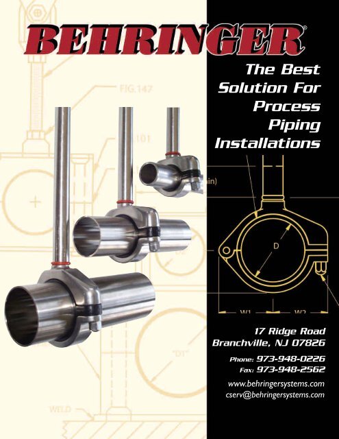
The Best<br />
Solution For<br />
Process<br />
Piping<br />
Installations<br />
17 Ridge Road<br />
Branchville, NJ 07826<br />
Phone: 973-948-0226<br />
Fax: 973-948-2562<br />
www.behringersystems.com<br />
cserv@behringersystems.com
Compact<br />
Hygienic<br />
CH SERIES HAS<br />
ALL YOUR ANGLES COVERED...<br />
CH<br />
Series<br />
<strong>Hangers</strong><br />
The innovative CH Series hangers design was developed with the<br />
input of engineers, contractors, end users and <strong>Behringer</strong>'s<br />
strong understanding of hygienic tube and pipe applications.<br />
These compact High Purity hangers answer industry concerns,<br />
while incorporating several contractor time-saving benefits. The<br />
tension ring connection on the Dynamic Hanger allows the clamp<br />
bodies to self adjust, independent of the hanging rod, to the<br />
tube's slope. This attribute reduces internal stress on the tube,<br />
as well as, eliminating an entire step during slope adjustment. The<br />
ability to make these adjustments, while the hanger is secured to<br />
the tubing, eliminates the step of retesting the slope after the<br />
hangers have been mounted. The combined use of the CH, CHT,<br />
CHR & CHW supports along with the telescoping stanchions<br />
permits line adjustment in the x, y and z axis's. What could prove<br />
to be biggest saver is these are packaged and installed as a one<br />
piece unit. No loose parts and wasted time gathering pieces and<br />
assembling components on ladders and space restricted areas.<br />
These benefits ultimately create a quality job.<br />
®<br />
ii Catalog CHSAN0109 WWW.BEHRINGERSYSTEMS.COM PHONE: 973-948-0226
Table of Contents<br />
CH Series<br />
Fig. 221 CH<br />
CH - Dynamic Mount Hanger Pages 4 - 5<br />
CHR - Rigid Mount Hanger Pages 6 - 7<br />
CHW - Weld Plate Mount Support Pages 8 - 9<br />
CHT - Threaded Mount Hanger Pages 10 - 11<br />
Fig. 245 - Threaded Support Rod Page 12<br />
Stanchions<br />
Fig. 223 - Telescopic Base Stand Page 13<br />
Fig. 224 - Rod Stand Plate Page 14<br />
Fig. 225 - Telescopic Adjusting Stanchion Hang Mount Page 15<br />
Fig. 226 - Telescopic Adjusting Page 16<br />
Stanchion Floor Mount Stand (Round or Square)<br />
Smooth Bore Series<br />
Fig. 200 - Smooth Bore Weld Plate Mount Page 17<br />
Fig. 201 - Smooth Bore Hang Plate Mount Page 18<br />
Fig. 202 - Smooth Bore Base Plate Mount Page 19<br />
Fig. 203 - Smooth Bore RAL-1 Rail Mounting Page 20<br />
Fig. 204 - Smooth Bore Stacking Kit Page 21<br />
Fig. 211 - Smooth Bore Unistrut Mount Page 22<br />
Fig. 221 - Smooth Bore Rod Mount Page 23<br />
Miscellaneous<br />
Fig. 109 - Heavy Series Anchor Clamp Page 24<br />
Fig. 251 - <strong>Sanitary</strong> Clamps Page 25<br />
Technical Data Material Properties, Pages 26-28<br />
Slope Conversion Chart, Shear Force Diagram<br />
For more information:<br />
visit our website at www.behringersystems.com<br />
or<br />
call our office at (973)948-0226<br />
PHONE: 973-948-0226 WWW.BEHRINGERSYSTEMS.COM Catalog CHSAN0109 1<br />
PATENT D553,971
Automatic Slope<br />
Adjustment<br />
Tension Ring connection allows hanger body to<br />
adjust 7º to tube slope and rotate 360º to<br />
relieve all unnecessary stresses between tube<br />
and “CH” support<br />
Telescopic - Elevation<br />
Adjustment<br />
CH Series with Stanchion allows for quick x, y and<br />
z axis adjustment for ease in locating tube’s direction,<br />
elevation and slope.<br />
One Piece unit<br />
Assembled as a one piece unit. No<br />
loose parts, quick identification<br />
and swift installation.Acorn bolt<br />
and plastics are captive to the<br />
“CH” Housing.<br />
Lot Traceabiity coming in<br />
2009<br />
<strong>Behringer</strong> will be instituting lot traceability<br />
and material identification for all stainless<br />
steel products.<br />
(exact locations will vary)<br />
2 Catalog CHSAN0109 WWW.BEHRINGERSYSTEMS.COM PHONE: 973-948-0226<br />
PATENT #D553,971
EXAMPLE ORDERING GUIDE<br />
CH Part # Configurator<br />
CHR -PS<br />
-150 -T -06<br />
Mounting Configuration<br />
Dynamic = CH<br />
Rigid = CHR<br />
Weld Plate = CHW<br />
Threaded = RHT<br />
Insert Material<br />
Anchor (Black) = PS<br />
Guide (Grey) = PG<br />
Rod Length (CH & CHR Only)<br />
06 = 6" OAL<br />
12 = 12" OAL<br />
24 = 24" OAL<br />
36 = 36" OAL<br />
Hardware Material<br />
T = 304 S/S<br />
X = 316 S/S<br />
Tube or Pipe Size<br />
1.5" Tube = 150<br />
1" Pipe = 132<br />
2" Pipe = 238<br />
Smooth Bore Part # Configurator<br />
H<br />
SB<br />
T<br />
3 100 -SP<br />
Mounting Configuration<br />
Weld Mount = (Omit)<br />
Hang Mount = H<br />
Base Plate = B<br />
Stacking Kit = SK<br />
Insert Material<br />
SP = Santoprene (tan)<br />
PP = Polypropylene blue)<br />
NN = HDPE (white)<br />
HT = Vekton (black)<br />
Smooth Bore Block Style<br />
Tube or Pipe Size<br />
100 = 1" Tube<br />
Hardware Material<br />
084=1/2"Pipe<br />
304 S/S = T<br />
316 S/S = X Group #<br />
Zinc Plated Carbon Steel = Z 3 = Group 3<br />
6 = Group 6<br />
7 = Group 7<br />
7A = Group 7A<br />
8 = Group 8 (where available)<br />
9 = Group 9 (where available)<br />
®<br />
PHONE: 973-948-0226 WWW.BEHRINGERSYSTEMS.COM Catalog CHSAN0109 3<br />
PATENT D553,971
PIPE &TUBE SUPPORT<br />
®<br />
PIPE &TUBE SUPPORT<br />
®<br />
FIG. 221 CH<br />
Housing with<br />
Black inserts<br />
are "Anchor"<br />
supports<br />
Dynamic "Anchor or Guide" Slope Adjusting Hanger/ Rod Mount Unit<br />
One piece unit with attached dynamic rod. Hanger rods are available in<br />
lengths ranging from min of 1.26" to 96". Standard length is 6”.<br />
DYNAMIC MOUNT HANGER<br />
Features: A dynamic union between the hanger rod and hanger housing<br />
allows for the housing to self adjust to the tubes slope for drainability as well<br />
as a 360 o swivel. A 6" rod is the standard length with other lengths available.<br />
Fig 221 CH can also be used in combination with the figure 223, 225 or 226<br />
stanchions. This combination will allow the support to be adjusted telescopically<br />
to the tube or pipe elevation. Call customer service for the price and<br />
availability of special rod lengths.<br />
Size Range: 0.24" diameters through 6.00" diameter covering imperial tube,<br />
pipe and copper sizes. ISO and DIN standards, and special diameters available<br />
upon request.<br />
Hardware: 304 stainless steel (Standard), 316 stainless steel<br />
Finish: Stainless steel at a 25 RA<br />
Plastic: Polysulfone (Black = Anchor and Gray = Guide)<br />
Shearing: Anchors - Refer to shear force diagram in technical section<br />
(page 27)<br />
Guides - Allows free axial movement for thermal expansion<br />
of tube or pipe<br />
Fig. 221CH Compact Dynamic Hanger - Part Number Configurator<br />
CH- PS- 079- T- 06<br />
Housing Type<br />
Compact Hygienic = CH<br />
Plastic Insert Material & Feature<br />
Anchor - Black = PS<br />
Guide - Gray = PG<br />
Tube, Pipe or Guide Size<br />
Anchor "D" Dimension<br />
For sizing refer to "D" column on dimensional chart<br />
"Round Part Number to the Hundredth 0" 0.79 = 079<br />
Hardware Material<br />
304 Stainless Steel = T<br />
316 Stainless Steel = X<br />
Housing with<br />
Gray inserts<br />
are "Guide"<br />
supports<br />
Dynamic Rod Length<br />
minimum lengthof of 1.26 = min<br />
Standard Length 6" = 06<br />
12" = 12<br />
18" = 18<br />
24" = 24<br />
36" = 36<br />
48" = 48<br />
96" = 96<br />
4 Catalog CHSAN0109 WWW.BEHRINGERSYSTEMS.COM PHONE: 973-948-0226<br />
PATENT #D553,971<br />
FIG. 221 CH<br />
Group No.<br />
1<br />
2<br />
8<br />
Pipe<br />
Copper Tube<br />
221 CH<br />
6mm CH-PS-024-T- 0.24 0.27<br />
1/4" CH-PS-025-T- 0.25 0.29<br />
3/8" CH-PS-038-T- 0.38 0.41<br />
1/2" CH-PS-050-T- 0.50 0.54<br />
1/4" CH-PS-054-T- 0.54 0.58<br />
3/4" CH-PS-075-T- 0.75 0.79<br />
j<br />
Part Number (-PS- as<br />
displayed is an Anchor<br />
& -PG- would make a<br />
Guide)<br />
20 mm CH-PS-079-T- 0.79 0.82<br />
1/2" CH-PS-084-T- 0.84 0.88<br />
3<br />
3/4" CH-PS-088-T- 0.88 0.91<br />
1" CH-PS-100-T- 1.00 1.04<br />
4<br />
Stainless Tube<br />
1/2"<br />
3/4" CH-PS-105-T- 1.05 1.09<br />
1" CH-PS-113-T- 1.13 1.16<br />
1" CH-PS-132-T- 1.32 1.35<br />
11/2" CH-PS-150-T- 1.50 1.54<br />
3" CH-PS-313-T- 3.13 3.18<br />
3" CH-PS-350-T- 3.50 3.55<br />
4" CH-PS-400-T- 4.00 4.05<br />
104 mm CH-PS-409-T- 4.09 4.14<br />
8A<br />
4" CH-PS-413-T- 4.13 4.18<br />
4" CH-PS-450-T- 4.50 4.55<br />
"D" Anchor Plastic<br />
UNIVERSAL DIMENSIONS<br />
AMONG HOUSINGS<br />
"G" Guide Plastic<br />
CH-PS-063-T- 0.63 0.66<br />
40 mm CH-PS-158-T- 1.58 1.61<br />
11/2" CH-PS-163-T- 1.63 1.66<br />
5<br />
11/2" CH-PS-190-T- 1.90 1.94<br />
2" CH-PS-200-T- 2.00 2.04<br />
52 mm CH-PS-205-T- 2.05 2.10<br />
2" CH-PS-213-T- 2.13 2.18<br />
6<br />
2" CH-PS-238-T- 2.38 2.43<br />
2 1/2" CH-PS-250-T- 2.50 2.55<br />
70 mm CH-PS-276-T- 2.76 2.81<br />
7<br />
2 1/2" CH-PS-288-T- 2.88 2.93<br />
3" CH-PS-300-T- 3.00 3.05<br />
129 mm CH-PS-508-T- 5.08 5.13<br />
9<br />
6" CH-PS-600-T- 6.00 6.05<br />
W1 W2 Z L, min U H<br />
DYNAMIC MOUNT HANGER<br />
PHONE: 973-948-0226 WWW.BEHRINGERSYSTEMS.COM Catalog CHSAN0109 5<br />
PATENT D553,971<br />
0.93<br />
(24)<br />
1.06<br />
(27)<br />
1.20<br />
(31)<br />
1.45<br />
(37)<br />
1.74<br />
(44)<br />
2.02<br />
(51)<br />
2.27<br />
(58)<br />
2.76<br />
(70)<br />
3.00<br />
(76)<br />
3.98<br />
(101)<br />
1.02<br />
(26)<br />
1.15<br />
(29)<br />
1.28<br />
(33)<br />
1.56<br />
(40)<br />
1.79<br />
(46)<br />
2.04<br />
(52)<br />
2.29<br />
(58)<br />
2.79<br />
(71)<br />
3.09<br />
(78)<br />
4.46<br />
(113)<br />
Dimension, in. (mm)<br />
0.75<br />
(19)<br />
)<br />
0.75<br />
(19)<br />
0.75<br />
(19)<br />
0.75<br />
(19)<br />
0.75<br />
(19)<br />
1.00<br />
(25)<br />
1.00<br />
(25)<br />
1.00<br />
(25)<br />
1.00<br />
(25)<br />
1.50<br />
(38)<br />
1.26<br />
(32)<br />
1.26<br />
(32)<br />
1.26<br />
(32)<br />
1.26<br />
(32)<br />
1.26<br />
(32)<br />
1.36<br />
(35)<br />
1.36<br />
(35)<br />
1.36<br />
(35)<br />
1.36<br />
(35)<br />
1.78<br />
(45)<br />
0.95<br />
(24)<br />
1.07<br />
(27)<br />
1.20<br />
(30)<br />
1.45<br />
(39)<br />
1.70<br />
(43)<br />
2.04<br />
(52)<br />
2.29<br />
(58)<br />
2.79<br />
(71)<br />
3.04<br />
(77)<br />
4.16<br />
(106)<br />
All standard sizes shown, special diameters available upon request<br />
221 CH<br />
1.54<br />
(39)<br />
1.77<br />
(45)<br />
2.04<br />
(52)<br />
2.53<br />
(65)<br />
3.03<br />
(77)<br />
3.63<br />
(92)<br />
4.13<br />
(105)<br />
5.13<br />
(131)<br />
5.63<br />
(143)<br />
7.74<br />
(197)<br />
Rod<br />
Diameter<br />
0.63<br />
(16)<br />
0.63<br />
(16)<br />
0.63<br />
(16)<br />
0.63<br />
(16)<br />
0.63<br />
(16)<br />
0.75<br />
(19)<br />
0.75<br />
(19)<br />
0.75<br />
(19)<br />
0.75<br />
(19)<br />
1.00<br />
(25)<br />
Weight, lb (kg)<br />
0.76<br />
(0.34)<br />
0.79<br />
(0.36)<br />
0.82<br />
(0.37)<br />
0.86<br />
(0.39)<br />
0.97<br />
(0.44)<br />
1.37<br />
(0.62)<br />
1.42<br />
(0.64)<br />
1.62<br />
(0.73)<br />
1.72<br />
(0.78)<br />
5.33<br />
(2.42)
PIPE &TUBE SUPPORT<br />
®<br />
PIPE &TUBE SUPPORT<br />
®<br />
FIG. 221 CHR<br />
Housing with<br />
Black inserts<br />
are "Anchor"<br />
supports<br />
Rigid “Anchor or Guide” Hanger / Rod Mount Unit<br />
RIGID MOUNT HANGER<br />
One piece unit with rod welded to the hanger housing. Hanger rods are available<br />
in lengths up to 96”. Standard rod length is 6”<br />
Features: The rigid hanger is ideal for supporting vertical runs and reducing<br />
vibrations. This type rod connection does not offer the dynamic slope adjustment.<br />
6" rod is the standard length with other lengths available. Fig 221<br />
CHR can also be used in combination with the figure 223, 225 or 226 stanchions.<br />
This combination will allow the support to be adjusted telescopically<br />
to the tube or pipe elevation. Call customer service for the price and availability<br />
of special rod lengths.<br />
Size Range: 0.24" diameters through 6.00" diameter covering imperial<br />
tube, pipe and copper sizes. ISO and DIN standards, and special diameters<br />
available upon request.<br />
Hardware: 304 stainless steel (Standard), 316 stainless steel also<br />
available upon request<br />
Finish: Stainless steel at a 25 RA<br />
Plastic: Polysulfone (Black = Anchor and Gray = Guide)<br />
Shearing: Anchors - Refer to shear force diagram in technical section<br />
(page 27)<br />
Guides - Allows free axial movement for thermal expansion<br />
of tube or pipe<br />
Housing with<br />
Gray inserts<br />
are "Guide"<br />
supports<br />
FIG. 221 CHR<br />
Group No.<br />
1<br />
2<br />
221 CHR<br />
6mm CHR-PS-024-T- 0.24 0.27<br />
1/4" CHR-PS-025-T- 0.25 0.29<br />
3/8" CHR-PS-038-T- 0.38 0.41<br />
1/2" CHR-PS-050-T- 0.50 0.54<br />
1/4" CHR-PS-054-T- 0.54 0.58<br />
3/4" CHR-PS-075-T- 0.75 0.79<br />
j<br />
Part Number (-PSas<br />
displayed is an<br />
Anchor & -PG- would<br />
make a Guide)<br />
1/2" CHR-PS-063-T- 0.63 0.66<br />
20 mm CHR-PS-079-T- 0.79 0.82<br />
1/2" CHR-PS-084-T- 0.84 0.88<br />
3<br />
3/4" CHR-PS-088-T- 0.88 0.91<br />
1" CHR-PS-100-T- 1.00 1.04<br />
4<br />
Stainless Tube<br />
Pipe<br />
Copper Tube<br />
3/4" CHR-PS-105-T- 1.05 1.09<br />
1" CHR-PS-113-T- 1.13 1.16<br />
1" CHR-PS-132-T- 1.32 1.35<br />
11/2" CHR-PS-150-T- 1.50 1.54<br />
40 mm CHR-PS-158-T- 1.58 1.61<br />
11/2" CHR-PS-163-T- 1.63 1.66<br />
5<br />
11/2" CHR-PS-190-T- 1.90 1.94<br />
"D" Anchor Plastic<br />
UNIVERSAL DIMENSIONS<br />
AMONG HOUSINGS<br />
"G" Guide Plastic<br />
W1 W2 Z U (min) H L<br />
0.93<br />
(24)<br />
1.06<br />
(27)<br />
1.20<br />
(31)<br />
1.45<br />
(37)<br />
1.74<br />
(44)<br />
1.02<br />
(26)<br />
1.15<br />
(29)<br />
1.28<br />
(33)<br />
1.56<br />
(40)<br />
1.79<br />
(46)<br />
Dimension, in. (mm)<br />
0.75<br />
(19)<br />
)<br />
0.75<br />
(19)<br />
0.75<br />
(19)<br />
0.75<br />
(19)<br />
0.75<br />
(19)<br />
1.08<br />
(28)<br />
1.23<br />
(31)<br />
1.35<br />
(34)<br />
1.66<br />
(42)<br />
1.85<br />
(47)<br />
1.67<br />
(42)<br />
1.93<br />
(49)<br />
2.19<br />
(56)<br />
2.74<br />
(69)<br />
3.18<br />
(81)<br />
RIGID MOUNT HANGER<br />
221 CHR<br />
<br />
<br />
<br />
<br />
<br />
Rod<br />
Diameter<br />
1/2"<br />
(12)<br />
1/2"<br />
(12)<br />
1/2"<br />
(12)<br />
1/2"<br />
(12)<br />
1/2"<br />
(12)<br />
Weights lb (kg)<br />
0.58<br />
(0.26)<br />
0.60<br />
(0.27)<br />
0.66<br />
(0.30)<br />
0.72<br />
(0.33)<br />
0.80<br />
(0.36)<br />
2" CHR-PS-200-T- 2.00 2.04<br />
Fig. 221 CHR Compact Rigid Hanger - Part Number Configurator<br />
CHR- PG- 105 – T- 06<br />
Housing Type<br />
Compact Hygienic Rigid = CHR<br />
6<br />
52 mm CHR-PS-205-T- 2.05 2.10<br />
2" CHR-PS-213-T- 2.13 2.18<br />
2" CHR-PS-238-T- 2.38 2.43<br />
2 1/2" CHR-PS-250-T- 2.50 2.55<br />
2.02<br />
(51)<br />
2.04<br />
(52)<br />
1.00<br />
(25)<br />
2.18<br />
(55)<br />
3.77<br />
(96)<br />
<br />
5/8"<br />
(19)<br />
1.61<br />
(0.73)<br />
Plastic Insert Material & Feature<br />
Anchor-Black=PS<br />
Guide - Gray = PG<br />
Tube, Pipe or Guide Size<br />
Anchor "D" Dimension<br />
For sizing refer to "D" column on dimensional chart<br />
Round Part Number to the Hundredth 1.05 = 105<br />
Hardware Material<br />
304 Stainless Steel = T<br />
316 Stainless Steel = X<br />
Rigid Rod Length<br />
Standard Length 6" = 06<br />
12" = 12<br />
18" = 18<br />
24" = 24<br />
Special lengths are available<br />
Upon Request<br />
70 mm CHR-PS-276-T- 2.76 2.81<br />
7<br />
2 1/2" CHR-PS-288-T- 2.88 2.93<br />
3" CHR-PS-300-T- 3.00 3.05<br />
8<br />
3" CHR-PS-313-T- 3.13 3.18<br />
3" CHR-PS-350-T- 3.50 3.55<br />
4" CHR-PS-400-T- 4.00 4.05<br />
104 mm CHR-PS-409-T- 4.09 4.14<br />
8A<br />
4" CHR-PS-413-T- 4.13 4.18<br />
4" CHR-PS-450-T- 4.50 4.55<br />
129 mm CHR-PS-508-T- 5.08 5.13<br />
9<br />
6" CHR-PS-600-T- 6.00 6.05<br />
2.27<br />
(58)<br />
2.76<br />
(70)<br />
3.01<br />
(76)<br />
3.98<br />
(101)<br />
2.29<br />
(58)<br />
2.79<br />
(71)<br />
3.09<br />
(78)<br />
4.46<br />
(113)<br />
1.00<br />
(25)<br />
1.00<br />
(25)<br />
1.00<br />
(25)<br />
1.50<br />
(38)<br />
2.34<br />
(59)<br />
3.08<br />
(78)<br />
3.28<br />
(83)<br />
4.45<br />
(113)<br />
4.18<br />
(106)<br />
5.42<br />
(137)<br />
5.87<br />
(149)<br />
8.03<br />
(204)<br />
All standard sizes shown, special diameters available upon request<br />
<br />
<br />
<br />
<br />
5/8"<br />
(19)<br />
3/4"<br />
(19)<br />
3/4"<br />
(19)<br />
1"<br />
(25)<br />
1.67<br />
(0.73)<br />
1.86<br />
(0.84)<br />
1.88<br />
(0.85)<br />
6.21<br />
(2.81)<br />
6 Catalog CHSAN0109 WWW.BEHRINGERSYSTEMS.COM PHONE: 973-948-0226<br />
PATENT #D553,971<br />
PHONE: 973-948-0226 WWW.BEHRINGERSYSTEMS.COM Catalog CHSAN0109 7<br />
PATENT D553,971
PIPE &TUBE SUPPORT<br />
®<br />
PIPE &TUBE SUPPORT<br />
®<br />
FIG. 221CHW<br />
Housing with<br />
Black inserts<br />
are "Anchor"<br />
supports<br />
WELD PLATE MOUNT SUPPORT<br />
Rigid “Anchor or Guide” Support with Weld Plate<br />
One piece unit with weld plate attached to hanger housing.<br />
Features: Compact housing is mounted on a weld plate. This type mounting<br />
configuration does not offer the dynamic slope adjustment feature. The CHW<br />
hanger is ideal for supporting vertical runs and reducing vibrations.<br />
Size Range: 0.24" diameters through 6.00" diameter covering imperial tube,<br />
pipe and copper sizes. ISO and DIN standards and special diameters available<br />
upon request.<br />
Hardware: 304 stainless steel (Standard), 316 stainless steel also available<br />
upon request<br />
Finish: Stainless steel at a 25 RA<br />
Plastic: Polysulfone (Black = Anchor and Gray = Guide)<br />
Shearing: Anchors - Refer to shear force diagram in technical section<br />
(page 27)<br />
Guides - Allows free axial movement for thermal expansion<br />
of tube or pipe<br />
Housing with<br />
Gray inserts<br />
are "Guide"<br />
supports<br />
FIG. 221CHW<br />
Group No.<br />
1<br />
2<br />
Pipe<br />
Copper Tube<br />
221 CHW<br />
6 mm CHW-PS-024-T 0.24 0.27<br />
1/4" CHW-PS-025-T 0.25 0.29<br />
3/8" CHW-PS-038-T 0.38 0.41<br />
1/2" CHW-PS-050-T 0.50 0.54<br />
1/4" CHW-PS-054-T 0.54 0.58<br />
3/4" CHW-PS-075-T 0.75 0.79<br />
j<br />
Part Number (-PSas<br />
displayed is an<br />
Anchor & -PG- would<br />
make a Guide)<br />
20 mm CHW-PS-079-T 0.79 0.82<br />
1/2" CHW-PS-084-T 0.84 0.88<br />
3<br />
3/4" CHW-PS-088-T 0.88 0.91<br />
1" CHW-PS-100-T 1.00 1.04<br />
4<br />
Stainless Tube<br />
"D" Anchor Plastic<br />
3/4" CHW-PS-105-T 1.05 1.09<br />
1" CHW-PS-113-T 1.13 1.16<br />
1" CHW-PS-132-T 1.32 1.35<br />
UNIVERSAL DIMENSIONS<br />
AMONG HOUSINGS<br />
"G" Guide Plastic<br />
1/2" CHW-PS-063-T 0.63 0.66<br />
W1 W2 Z U H T L W<br />
0.93<br />
(24)<br />
1.06<br />
(27)<br />
1.20<br />
(31)<br />
1.45<br />
(37)<br />
1.02<br />
(26)<br />
1.15<br />
(29)<br />
1.28<br />
(33)<br />
1.56<br />
(39)<br />
0.75<br />
(19)<br />
)<br />
0.75<br />
(19)<br />
0.75<br />
(19)<br />
0.75<br />
(19)<br />
Dimension, in. (mm)<br />
1.17<br />
(30)<br />
1.32<br />
(33)<br />
1.44<br />
(37)<br />
1.75<br />
(44)<br />
WELD PLATE MOUNT SUPPORT<br />
1.76<br />
(45)<br />
2.02<br />
(51)<br />
2.28<br />
(58)<br />
2.83<br />
(72)<br />
221 CHW<br />
3/16"<br />
(4.7)<br />
3/16"<br />
(4.7)<br />
3/16"<br />
(4.7)<br />
3/16"<br />
(4.7)<br />
1.50<br />
(38)<br />
1.50<br />
(38)<br />
1.50<br />
(38)<br />
1.75<br />
(44)<br />
1.50<br />
(38)<br />
1.50<br />
(38)<br />
1.50<br />
(38)<br />
1.75<br />
(44)<br />
Weights, lb (kg)<br />
0.37<br />
(0.17)<br />
0.39<br />
(0.18)<br />
0.44<br />
(0.20)<br />
0.56<br />
(0.25)<br />
1 1/2" CHW-PS-150-T 1.50 1.54<br />
40 mm CHW-PS-158-T 1.58 1.61<br />
5<br />
1 1/2" CHW-PS-163-T 1.63 1.66<br />
1 1/2" CHW-PS-190-T 1.90 1.94<br />
1.74<br />
(44)<br />
1.79<br />
(46)<br />
0.75<br />
(19)<br />
1.94<br />
(49)<br />
3.27<br />
(83)<br />
3/16"<br />
(4.7)<br />
1.75<br />
(44)<br />
1.75<br />
(44)<br />
0.63<br />
(0.28)<br />
2" CHW-PS-200-T 2.00 2.04<br />
1.45<br />
52 mm CHW-PS-205-T 2.05 2.10<br />
6<br />
2" CHW-PS-213-T 2.13 2.18<br />
2" CHW-PS-238-T 2.38 2.43<br />
2.02<br />
(51)<br />
2.04<br />
(52)<br />
1.00<br />
(25)<br />
2.27<br />
(58)<br />
3.86<br />
(98)<br />
3/16"<br />
(4.7)<br />
2.50<br />
(64)<br />
1.75<br />
(44)<br />
0.90<br />
(0.41)<br />
Fig. 221 CHW Weld Plate Mount Support - Part Number Configurator<br />
CHW- PS- 413- T<br />
Housing Type<br />
Compact Hygienic Weld Plate Mounted = CHW<br />
Plastic Insert Material & Feature<br />
Anchor Black = PS<br />
Guide Gray = PG<br />
Tube, Pipe or Guide Size<br />
Anchor "D" Dimension<br />
For sizing refer to "D" column on dimensional chart<br />
Round part number to the Hundredth 4.13 = 413<br />
Hardware Material<br />
304 Stainless Steel = T<br />
316 Stainless Steel = X<br />
8 Catalog CHSAN0109 WWW.BEHRINGERSYSTEMS.COM PHONE: 973-948-0226<br />
PATENT #D553,971<br />
2 1/2" CHW-PS-250-T 2.50 2.55<br />
70 mm CHW-PS-276-T 2.76 2.81<br />
7<br />
2 1/2" CHW-PS-288-T 2.88 2.93<br />
3" CHW-PS-300-T 3.00 3.05<br />
8<br />
3" CHW-PS-313-T 3.13 3.18<br />
3" CHW-PS-350-T 3.50 3.55<br />
4" CHW-PS-400-T 4.00 4.05<br />
104 mm CHW-PS-409-T 4.09 4.14<br />
8A<br />
4" CHW-PS-413-T 4.13 4.18<br />
4" CHW-PS-450-T 4.50 4.55<br />
129 mm CHW-PS-508-T 5.08 5.13<br />
9<br />
6" CHW-PS-600-T 6.00 6.05<br />
2.27<br />
(58)<br />
2.76<br />
(70)<br />
3.00<br />
(76)<br />
3.98<br />
(101)<br />
PHONE: 973-948-0226 WWW.BEHRINGERSYSTEMS.COM Catalog CHSAN0109 9<br />
PATENT D553,971<br />
2.29<br />
(58)<br />
2.79<br />
(71)<br />
3.09<br />
(78)<br />
4.46<br />
(113)<br />
1.00<br />
(25)<br />
1.00<br />
(25)<br />
1.00<br />
(25.4)<br />
1.50<br />
(38)<br />
2.43<br />
(62)<br />
3.17<br />
(81)<br />
3.37<br />
(86)<br />
4.54<br />
(115)<br />
4.27<br />
(108)<br />
5.51<br />
(140)<br />
5.96<br />
(151)<br />
8.12<br />
(206)<br />
.<br />
3/16"<br />
(4.7)<br />
3/16"<br />
(4.7)<br />
3/16"<br />
(4.7)<br />
1/4"<br />
(6.4)<br />
All standard sizes shown, special diameters available upon request<br />
2.50<br />
(64)<br />
2.50<br />
(64)<br />
2.50<br />
(64)<br />
4.00<br />
(108)<br />
1.75<br />
(44)<br />
1.75<br />
(44)<br />
1.75<br />
(44)<br />
1.75<br />
(44)<br />
0.96<br />
(0.43)<br />
1.15<br />
(0.52)<br />
1.17<br />
(0.53)<br />
4.67<br />
(2.12)
PIPE &TUBE SUPPORT<br />
® ®<br />
PIPE &TUBE SUPPORT<br />
FIG. 221 CHT<br />
Housing with<br />
Black inserts<br />
are "Anchor"<br />
supports<br />
Threaded "Anchor or Guide" Hanger<br />
HANGER/THREAD MOUNT UNIT<br />
One piece unit with threaded adaptor. Rod is sold separately<br />
Features: The threaded mounting section, on top of housing, doubles as a<br />
threaded rod connecter and a welding platform. This type rod connection<br />
does not offer the dynamic slope adjustment feature. Figure 221 CHT, with a<br />
rod, can also be used in combination with the figure 223, 225 or 226 stanchions.<br />
This combination will allow the support to be adjusted telescopically<br />
to the tube or pipe elevation. Call customer service for the price and availability<br />
of special rod lengths.<br />
Size Range: 0.24" diameters through 6.00" diameter covering imperial tube,<br />
pipe and copper sizes. ISO and DIN standards, and special diameters available<br />
upon request.<br />
Hardware: 304 stainless steel (Standard), 316 stainless steel also available<br />
upon request<br />
Finish: Stainless steel at a 25 RA<br />
Plastic: Polysulfone (Black = Anchor and Gray = Guide)<br />
Shearing: Anchors - Refer to shear force diagram in technical section<br />
(page 27)<br />
Guides - Allows free axial movement for thermal expansion<br />
of tube or pipe<br />
Housing with<br />
Gray inserts<br />
are "Guide"<br />
supports<br />
FIG. 221 CHT<br />
Group No.<br />
1<br />
2<br />
Stainless Tube<br />
Pipe<br />
Copper Tube<br />
221 CHT<br />
6 mm CHT-PS-024-T 0.24 0.27<br />
1/4" CHT-PS-025-T 0.25 0.29<br />
3/8" CHT-PS-038-T 0.38 0.41<br />
1/2" CHT-PS-050-T 0.50 0.54<br />
1/4" CHT-PS-054-T 0.54 0.58<br />
1/2" CHT-PS-063-T 0.63 0.66<br />
3/4" CHT-PS-075-T 0.75 0.79<br />
j<br />
Part Number (-PSas<br />
displayed is an<br />
Anchor & -PG- would<br />
make a Guide)<br />
20 mm CHT-PS-079-T 0.79 0.82<br />
1/2" CHT-PS-084-T 0.84 0.88<br />
3<br />
3/4" CHT-PS-088-T 0.88 0.91<br />
1" CHT-PS-100-T 1.00 1.04<br />
4<br />
3/4" CHT-PS-105-T 1.05 1.09<br />
1" CHT-PS-113-T 1.13 1.16<br />
1" CHT-PS-132-T 1.32 1.35<br />
1 1/2" CHT-PS-150-T 1.50 1.54<br />
40 mm CHT-PS-158-T 1.58 1.61<br />
1 1/2" CHT-PS-163-T 1.63 1.66<br />
5<br />
1 1/2" CHT-PS-190-T 1.90 1.94<br />
2" CHT-PS-200-T 2.00 2.04<br />
"D" Anchor Plastic<br />
UNIVERSAL DIMENSIONS<br />
AMONG HOUSINGS<br />
"G" Guide Plastic<br />
W1 W2 Z U H<br />
0.93<br />
(24)<br />
1.06<br />
(27)<br />
1.20<br />
(31)<br />
1.46<br />
(37)<br />
1.74<br />
(44)<br />
1.02<br />
(26)<br />
1.15<br />
(29)<br />
1.28<br />
(33)<br />
1.56<br />
(40)<br />
1.79<br />
(46)<br />
Dimension, in. (mm)<br />
0.75<br />
(19)<br />
)<br />
0.75<br />
(19)<br />
0.75<br />
(19)<br />
0.75<br />
(19)<br />
0.75<br />
(19)<br />
1.08<br />
(28)<br />
1.23<br />
(31)<br />
1.35<br />
(34)<br />
1.66<br />
(42)<br />
1.85<br />
(47)<br />
THREADED MOUNT HANGER<br />
1.67<br />
(42)<br />
1.93<br />
(49)<br />
2.19<br />
(56)<br />
2.74<br />
(69)<br />
3.18<br />
(81)<br />
221 CHT<br />
Thread<br />
5/16"-18<br />
(10)<br />
5/16"-18<br />
(10)<br />
5/16"-18<br />
(10)<br />
5/16"-18<br />
(10)<br />
5/16"-18<br />
(10)<br />
Rod Diameter<br />
(Sold<br />
Separtely)<br />
1/2"<br />
(12)<br />
B<br />
1/2"<br />
(12)<br />
B<br />
1/2"<br />
(12)<br />
B<br />
1/2"<br />
(12)<br />
B<br />
1/2"<br />
(12)<br />
B<br />
Weights lb (kg)<br />
0.26<br />
(0.12)<br />
0.28<br />
(0.13)<br />
0.33<br />
(0.15)<br />
0.40<br />
(0.18)<br />
0.48<br />
(0.22)<br />
Fig. 221 CHT Compact Threaded Mount Hanger - Part Number Configurator<br />
CHT- PG- 150 T<br />
Housing Type<br />
Compact Hygienic Threaded = CHT<br />
6<br />
52 mm CHT-PS-205-T 2.05 2.10<br />
2" CHT-PS-213-T 2.13 2.18<br />
2" CHT-PS-238-T 2.38 2.93<br />
2 1/2" CHT-PS-250-T 2.50 2.55<br />
2.02<br />
(51)<br />
2.04<br />
(52)<br />
1.00<br />
(25)<br />
2.18<br />
(55)<br />
3.77<br />
(96)<br />
3/8"-16<br />
(10)<br />
5/8"<br />
(19)<br />
C<br />
0.70<br />
(0.32)<br />
Plastic Insert Material & Feature<br />
Anchor - Black = PS<br />
Guide - Gray = PG<br />
Tube, Pipe or Guide Size<br />
Anchor "D" Dimension<br />
For sizing refer to "D" column on dimensional chart<br />
Round Part Number to the Hundredth 1.50 = 150<br />
7<br />
8<br />
70 mm CHT-PS-276-T 2.76 2.81<br />
2 1/2" CHT-PS-288-T 2.88 2.93<br />
3" CHT-PS-300-T 3.00 3.05<br />
3" CHT-PS-313-T 3.13 3.18<br />
3" CHT-PS-350-T 3.50 3.55<br />
4" CHT-PS-400-T 4.00 4.05<br />
2.27<br />
(58)<br />
2.76<br />
(70)<br />
2.29<br />
(58)<br />
2.79<br />
(71)<br />
1.00<br />
(25)<br />
1.00<br />
(25)<br />
2.34<br />
(59)<br />
3.08<br />
(78)<br />
4.18<br />
(106)<br />
5.42<br />
(137)<br />
3/8"-16<br />
(10)<br />
1/2"-13<br />
(16)<br />
5/8"<br />
(19)<br />
C<br />
3/4"<br />
(19)<br />
D<br />
0.76<br />
(0.34)<br />
0.95<br />
(0.43)<br />
Hardware Material<br />
304 Stainless Steel = T<br />
316 Stainless Steel = X<br />
104 mm CHT-PS-409-T 4.09 4.14<br />
8A<br />
4" CHT-PS-413-T 4.13 4.18<br />
4" CHT-PS-450-T 4.50 4.55<br />
3.00<br />
(76)<br />
3.09<br />
(78)<br />
1.00<br />
(25.4)<br />
3.28<br />
(83)<br />
5.87<br />
(149)<br />
1/2"-13<br />
(16)<br />
3/4"<br />
(19)<br />
D<br />
0.97<br />
(0.44)<br />
**See Figure 245 to Order Threaded Rod Separately**<br />
129 mm CHT-PS-508-T 5.08 5.13<br />
9<br />
6" CHT-PS-600-T 6.00 6.05<br />
10 Catalog CHSAN0109 WWW.BEHRINGERSYSTEMS.COM PHONE: 973-948-0226<br />
PHONE: 973-948-0226 WWW.BEHRINGERSYSTEMS.COM Catalog CHSAN0109 11<br />
PATENT #D553,971 PATENT D553,971<br />
3.98<br />
(101)<br />
4.46<br />
(113)<br />
1.50<br />
(38)<br />
4.46<br />
(113)<br />
8.04<br />
(204)<br />
All standard sizes shown, special diameters available upon request<br />
3/4"-10<br />
(20)<br />
1"<br />
(25)<br />
E<br />
4.20<br />
(1.90)
PIPE &TUBE SUPPORT<br />
FIG. 245<br />
THREADED SUPPORT ROD<br />
®<br />
Size Range: 3/8" outside diameter to 1" outside diameter with different rod lengths and<br />
connection threads avialable.<br />
Hardware Material: 304 or 316 Stainless Steel; Carbon or Electro-Zinc Plated Carbon Steel<br />
Finish: 25 Ra (for 304/316); Other available upon request<br />
Ordering: To identify the proper thread refer to the "T" column on Fig. 221CHT or the<br />
Hang Nut column on Fig. 201. Then use the Fig 245 part number configuator<br />
located at the bottom of this page.<br />
Installations: Thread the rod into housing. Cut the rod in the field to proper length. Field<br />
weld the rod to support structure. The rod can also be used in combination<br />
with the figure 223, 225 or 226 stanchions. This combination will allow<br />
the support to be adjusted telescopically to the tube or pipe elevation.<br />
Fig. 225 Telescopic Rod Adjustment<br />
to the tubes elevation<br />
Fig. 226 Telescopic Rod Adjustment<br />
to the tubes elevation<br />
Fig. 245 Threaded Support Rod - Part Number Configurator<br />
ROD -038 -T -B -25 -06<br />
Style<br />
Rod Length (unthreaded section)<br />
Hanger Rod = ROD 03 = 3"<br />
06 = 6"<br />
Hanger Rod Thread<br />
12 = 12"<br />
5/16-18 = 031 24 = 24"<br />
3/8-16 = 038 36 = 36"<br />
1/2-13 = 050<br />
48 = 48"<br />
5/8-11 = 063<br />
96 = 96"<br />
3/4-10 = 075<br />
Hardware Material<br />
Finish<br />
304 Stainless Steel = T 25 = 25Ra<br />
316 Stainless Steel = X<br />
Carbon = C<br />
Rod Diameter<br />
Zinc = Z<br />
A =3/8"<br />
B=1/2"<br />
C=5/8"<br />
D=3/4"<br />
E=1"<br />
12 Catalog CHSAN0109 WWW.BEHRINGERSYSTEMS.COM PHONE: 973-948-0226
PIPE &TUBE SUPPORT<br />
®<br />
FIG. 223<br />
TELESCOPIC ADJUSTING ROUND FLOOR MOUNT STAND<br />
The Telescopic Adjusting Round Floor Mount Stand allows the housing’s rod elevation to<br />
be adjusted up to 2” from the base plate’s surface. The rod attached to the housing slides<br />
inside the base plate’s elevation adjustment tube. This fine tune adjustment allows the<br />
installer to quickly change the support’s elevation to match the tube’s distance from the<br />
floor. The base plate can be supplied with or without anchor bolt holes. Anchor bolts not<br />
supplied by <strong>Behringer</strong>.<br />
Base Plate Sizing: RSP1 & RSP2 - 0.25” to 2.00” OD tube & pipe sizes<br />
RSP3 & RSP4 - 2.05” to 4.50” OD tube & pipe sizes<br />
RSP5 & RSP6 - 5.08” to 6.00” OD tube & pipe sizes<br />
Hardware Material: 304 stainless steel, 316 stainless steel, carbon steel & zinc plated<br />
Finish: MILL = Fabricated steel and welds are a mill finish<br />
BUFF = Fabricated steel and weld are buffed to remove splatter<br />
BLND = Fabricated steel is polished and welds are blended<br />
Special finishes and painted stands are available, call <strong>Behringer</strong><br />
Clamp & Rod Sold Separately<br />
Fig. 223 Telescopic Adjusting Round Floor Mount Stand<br />
TBS-<br />
X- B- RSP1-<br />
MILL<br />
Telescopic Base Stand<br />
Finish<br />
MILL = Fabricated steel and welds are a mill finish<br />
Hardware Material<br />
BUFF = Fabricated steel and weld are buffed to remove splatter<br />
304 Stainless Steel = T BLND = Fabricated steel is polished and welds are blended<br />
316 Stainless Steel = X SPL = Special finishes available, call <strong>Behringer</strong><br />
Electro-Zinc plated carbon = Z<br />
Carbon Steel = C<br />
Rod Stand Plate Sizes<br />
Painted "to end users specification" = P<br />
RSP1- = 4" x 4" x 1/4" base plate with four 7/16" anchor bolt holes<br />
RSP2- = 4" x 4" x 1/4" base plate without anchor bolt holes<br />
Support Rod OD<br />
RSP3- = 6" x 4" x 1/4" base plate with four 7/16" anchor bolt holes<br />
3/8" = A RSP4- = 6" x 4" x 1/4" base plate without anchor bolt holes<br />
1/2" = B RSP5- = 8" x 6" x 3/8" base plate with four 9/16" anchor bolt holes<br />
5/8" = C RSP6- = 8" x 6" x 3/8" base plate without anchor bolt holes<br />
3/4" = D<br />
1" = E<br />
PHONE: 973-948-0226 WWW.BEHRINGERSYSTEMS.COM Catalog CHSAN0109 13<br />
PATENT D553,971
PIPE &TUBE SUPPORT<br />
FIG. 224<br />
CH SERIES ROD STAND PLATE<br />
®<br />
One piece CH Series Rod Stand Plate with rod cut to specified length. The rod is welded to<br />
the base plate, which can be supplied with or without anchor bolt-holes. Anchor bolts not<br />
supplied by <strong>Behringer</strong>.<br />
The height is calculated from the top of the plate to centerline of tube or pipe. Please refer<br />
to “U” min column in catalog for minimum height of the required RH series product.<br />
Base Plate Sizing: RSP1 & RSP2 - 0.25” to 2.00” OD tube & pipe sizes<br />
RSP3 & RSP4 - 2.05” to 4.50” OD tube & pipe sizes<br />
RSP5 & RSP6 - 5.08” to 6.00” OD tube & pipe sizes<br />
Hardware Material: 304 stainless steel, 316 stainless steel<br />
Finish: MILL = Fabricated steel and welds are a mill finish<br />
BUFF = Fabricated steel and weld are buffed to remove splatter<br />
BLND = Fabricated steel is polished and welds are blended<br />
Special finishes and painted stands are available, call <strong>Behringer</strong><br />
Housing Type<br />
Compact Hygienic Dynamic = CH<br />
Compact Hygienic Threaded = CHT<br />
Compact Hygienic Rigid = CHR<br />
Plastic Insert Feature<br />
Anchor - Black = PS<br />
Guide - Gray = PG<br />
Tube or Pipe as an Achor or Guide<br />
Anchor sizing refer to "D" Dimension<br />
Guide sizing refer to "G" Dimension<br />
Refer to any RH Series dimensional chart<br />
Fig. 224 CH Series Rod Stand Plate - Part Number Configurator<br />
CHR - PS - 100 - X - 06 - RSP1 - BLND<br />
Finish<br />
MILL = Fabricated steel and welds are a mill finish<br />
BUFF = Fabricated steel and weld are buffed to remove splatter<br />
BLND = Fabricated steel is polished and welds are blended<br />
SPL = Special finishes abailable, call <strong>Behringer</strong><br />
Rod Stand Plate Sizes<br />
RSP1- = 4" x 4" x 1/4" base plate with four 7/16" anchor bolt holes<br />
RSP2- = 4" x 4" x 1/4" base plate without anchor bolt holes<br />
RSP3- = 6" x 4" x 1/4" base plate with four 7/16" anchor bolt holes<br />
RSP4- = 6" x 4" x 1/4" base plate without anchor bolt holes<br />
RSP5- = 8" x 6" x 3/8" base plate with four 9/16" anchor bolt holes<br />
RSP6- = 8" x 6" x 3/8" base plate without anchor bolt holes<br />
Hardware Material<br />
Height "U" Dimension (measured from top of plate to tube or pipe centerline)<br />
304 Stainless Steel = -T 02.33 = 2.33" top of plate to center line<br />
316 Stainless Steel = -X 06 = 6" top of plate to center line<br />
Painted to end users specification = -P<br />
12.5 = 12.5" top of plate to center line<br />
14 Catalog CHSAN0109 WWW.BEHRINGERSYSTEMS.COM PHONE: 973-948-0226<br />
PATENT #D553,971
PIPE &TUBE SUPPORT<br />
®<br />
FIG. 225<br />
TELESCOPIC ADJUSTING STANCHION - HANG MOUNT<br />
Hanger Stanchion with square or round tube cut to specified length. One end of the<br />
tube has a capped end with a rod hole. The rod hole is used for telescopic<br />
adjustment of the hanger rod. Specify the steel finish and the finish on the weld.<br />
Features: Hole in capped end of tube allows the hanger rod to be manually<br />
adjusted for telescopic location of the tube or pipe.<br />
Hardware: 304 stainless steel; 316 stainless steel, carbon steel & zinc plated<br />
carbon steel<br />
Finish: MILL = Fabricated steel and welds are a mill finish<br />
BUFF = Fabricated steel and welds are buffed to remove splatter<br />
BLND = Fabricated steel is polished and welds are blended<br />
Special finishes and painted stanchions are available, call <strong>Behringer</strong><br />
Fig 225 Telescopic Hang Mount Stanchion - Part Number Configurator<br />
Stanchion Length<br />
Finish<br />
6" = S06<br />
MILL = Fabricated steel and welds are a mill finish<br />
12" = S12<br />
BUFF = Fabricated steel and weld are buffed to remove splatter<br />
18" = S18<br />
BLND = Fabricated steel is polished and welds are blended<br />
24" = S24<br />
36" = S36<br />
SPL = Special finishes available, call <strong>Behringer</strong><br />
48" = S48 Hardware<br />
96" = S96<br />
T = 304 Stainless Steel<br />
X = 316 Stainless Steel<br />
Rod Hole Diameter<br />
Z = Electro-Zinc plated carbon<br />
Capped end with 3/8" rod hole = A<br />
C = Carbon Steel<br />
Capped end with 1/2" rod hole = B<br />
P = Painted to end users specification<br />
Capped end with 5/8" rod hole = C<br />
Capped end with 3/4" rod hole = D<br />
XXX = no base plate<br />
Capped end with 1" rod hole = E<br />
(For Base plate p/n see Fig 226)<br />
Capped end with no rod hole = F<br />
Square Tube Size<br />
1-1/2" x 1-1/2" x 1/8" sq. tube = SW1<br />
2" x 2" x 1/8" sq. tube = SW2<br />
3" x 3" x 3/16" sq. tube = SW3<br />
S12 B -SW1 -XXX -T -MILL<br />
<br />
Round Tube Size<br />
RW1 = 1-1/2" SCH 40 Round Pipe<br />
RW2 = 2" SCH 40 Round Pipe<br />
RW3 = 3" SCH 40 Round Pipe<br />
PHONE: 973-948-0226 WWW.BEHRINGERSYSTEMS.COM Catalog CHSAN0109 15
PIPE &TUBE SUPPORT<br />
®<br />
FIG. 201<br />
HANG PLATE MOUNT<br />
Size Range: 1/4” outside diameter through 6.625” diameter<br />
Hardware Material: 304 Stainless, 316 Stainless, or electro-zinc plated carbon<br />
Plastic Inserts: Polypropylene (blue) up to 212° F<br />
Santoprene (beige) up to 302° F<br />
HDPE (white) up to 180° F<br />
Vekton (black) up to 350° F<br />
Installations: Hang from threaded rod to desired elevation<br />
Thermal Expansion Guide: -(Optional) Provides for axial expansion of the tube or pipe due to thermal<br />
expansion. One set of two per clamp (Inside Back Cover)<br />
Thermal Expansion Guide<br />
Material: Santoprene, 1/16" insert, Black for service identification<br />
GRP<br />
NO.<br />
3<br />
6<br />
7<br />
TUBE OR<br />
PIPE SIZE<br />
"D"<br />
INCHES<br />
1/4 T 0.250<br />
3/8 T 0.375<br />
1/2 T 0.500<br />
3/4 T 0.750<br />
1/2 P 0.840<br />
1 T 1.000<br />
1/4 T 0.250<br />
3/8 T 0.375<br />
1/2 T 0.500<br />
5/8 T 0.625<br />
3/4 T 0.750<br />
1/2 P 0.840<br />
7/8 T 0.875<br />
1 T 1.000<br />
3/4 P 1.050<br />
1-1/4 T 1.250<br />
1 P 1.315<br />
1-1/2 T 1.500<br />
1-1/4 P 1.660<br />
1-1/2 P 1.900<br />
2 T 2.000<br />
2 T 2.000<br />
2 P 2.375<br />
2-1/2 T 2.500<br />
2-1/2 P 2.875<br />
3 T 3.000<br />
3-1/2 T -3 P 3.500<br />
W<br />
1.88"<br />
(48 mm)<br />
3.34"<br />
(85 mm)<br />
5.00"<br />
(127 mm)<br />
H Z U<br />
1.38"<br />
(35 mm)<br />
1.19"<br />
(30 mm)<br />
0.81"<br />
(20 mm)<br />
BOLT<br />
SIZE<br />
1/4-20<br />
HANG<br />
NUT<br />
3/8-16<br />
LBS.<br />
2.63" 1.19" 1.44"<br />
0.5<br />
(67 mm) (30 mm) (37 mm) 1/4-20 3/8-16 (0.23 kg)<br />
4.38"<br />
(111 mm)<br />
1.19"<br />
(30 mm)<br />
0.3<br />
(0.14 kg)<br />
2.31" 1.00<br />
1/4-20 3/8-16<br />
(59 mm) (0.45 kg)<br />
7A<br />
4 T 4.000<br />
5.77" 4.8" 1.19" 2.54" 1/4-20 3/8-16 1.30<br />
(147 mm) (122 mm) (33 mm) (65 mm) (0.59 kg)<br />
6 T 6.000 8.88" 7.65" 1.50" 4.01" 4.00<br />
8 3/8 - 16 5/8-11<br />
6P 6.625 (226 mm) (194 mm) (38 mm) (102 mm) (1.8 kg)<br />
Fig 201 Smooth Bore Hang Mount - Part Number Configurator<br />
H SB T 6 200<br />
H ang Plate Mount<br />
Thermal Expansion Guide (optional)<br />
Hang Plate Mount Fig. 201 = H<br />
TEG = Thermal Expansion Guide (optional)<br />
Style<br />
Plastic Insert Material<br />
Smooth Bore Block Style = SB<br />
PP- = Polypropylene, Blue (available in Groups 1-7A)<br />
SP- = Santoprene, Beige (available in Groups 1-8)<br />
Hardware Material NN- = HDPE, White (available in Group 8)<br />
304 Stainless Steel = T<br />
HT- = Vekton, Black (available in Groups 8 & 9)<br />
316 Stainless Steel = X<br />
Electro-zinc plated carbon = Z<br />
Tube or Pipe Size<br />
"D" Dimension<br />
Hardware Group Size<br />
For sizing refer to "D" column on dimensional chart<br />
Group 3 Hardware Size Tube OD and Pipe sizes ranging from 0.25" to 1" = 3<br />
apply the number in column without the decimal<br />
Group 6 Hardware Size Tube OD and Pipe sizes ranging from 0.25" to 2" = 6<br />
Group 7 Hardware Size Tube OD and Pipe sizes ranging from 2" to 3.50" = 7<br />
Examples of column "D" translation:<br />
Group 7A Hardware Size 4" Tube OD = 7A<br />
1/4" Tube = 025<br />
Group 8 Hardware Size Tube OD and Pipe sizes ranging from 6" to 6.625" = 8<br />
3/4" Pipe = 1050<br />
1" Pipe = 1315<br />
2" Pipe = 2375<br />
4" Tube = 400<br />
18 Catalog CHSAN0109 WWW.BEHRINGERSYSTEMS.COM PHONE: 973-948-0226<br />
SP<br />
(-TEG)
PIPE &TUBE SUPPORT<br />
FIG. 202<br />
Size Range: 1/4" outside diameter through 6.625" outside diameter<br />
SLOTTED BASE PLATE MOUNT<br />
®<br />
Hardware Material: 304 Stainless, 316 Stainless, or electro-zinc plated carbon<br />
Plastic Insert: Polypropylene (blue) up to 212º F<br />
Santoprene (tan) up to 302º F<br />
HDPE (white) up to 180º F<br />
Vekton (black) up to 350° F<br />
Installation: Locate bolt holes in mounting structure and either tap into structure or use<br />
1/4-20 bolt and nut to secure<br />
Thermal Expansion Guide: -(Optional) Provides for axial expansion of the tube or pipe due to thermal<br />
expansion. One set of two per clamp (Inside Back Cover)<br />
Thermal Expansion Guide<br />
Material: Santoprene, 1/16" insert, Black for service identification<br />
GROUP<br />
NO.<br />
3<br />
6<br />
7<br />
7A<br />
8<br />
TUBE OR<br />
PIPE SIZE<br />
1/4 T 0.250<br />
3/8 T 0.375<br />
1/2 T 0.500<br />
3/4 T 0.750<br />
1/2 P 0.840<br />
1 T 1.000<br />
1/4 T 0.250<br />
3/8 T 0.375<br />
1/2 T 0.500<br />
5/8 T 0.625<br />
3/4 T 0.750<br />
1/2 P 0.840<br />
7/8 T 0.875<br />
1 T 1.000<br />
3/4 P 1.050<br />
1-1/4 T 1.250<br />
1 P 1.315<br />
1-1/2 T 1.500<br />
1-1/4 P 1.660<br />
1-1/2 P 1.900<br />
2 T 2.000<br />
2 T 2.000<br />
2 P 2.375<br />
2-1/2 T 2.500<br />
2-1/2 P 2.875<br />
3 T 3.000<br />
3-1/2 T - 3 P 3.500<br />
4 T 4.000<br />
6 T<br />
6P<br />
"D"<br />
INCHES<br />
6.000<br />
6.625<br />
W<br />
1.88<br />
" (48<br />
mm)<br />
5.00<br />
"<br />
(127<br />
mm)<br />
5.77<br />
"<br />
(147<br />
mm)<br />
8.88<br />
"<br />
(226<br />
mm)<br />
H<br />
1.38<br />
" (35<br />
mm)<br />
3.34 2.63<br />
" (85 " (67<br />
mm) mm)<br />
4.38<br />
"<br />
(111<br />
mm)<br />
4.8"<br />
(122<br />
mm)<br />
7.65<br />
"<br />
(194<br />
mm)<br />
Fig 202 Smooth Bore Base Plate Mount - Part Number Configurator<br />
Z<br />
1.19"<br />
(30<br />
mm)<br />
1.19"<br />
(30<br />
mm)<br />
1.19"<br />
(30<br />
mm)<br />
1.19"<br />
(33<br />
mm)<br />
1.50"<br />
(38<br />
mm)<br />
INCHES<br />
B SB X 3 100 -SP (-TEG)<br />
Thermal Expansion Guide (optional)<br />
Base Plate Mount Plate<br />
-TEG = Thermal Expansion Guide<br />
Base Plate Mount Fig 202 = B<br />
Plastic Insert Material<br />
Style<br />
PP- = Polypropylene, Blue (available in Groups 1-7A)<br />
Smooth Bore Block Style = SB<br />
SP- = Santoprene, Beige (available in Groups 1-8)<br />
NN- = HDPE, White (Group 8)<br />
Hardware Material HT- = Vekton, Black (available in Groups 8 & 9)<br />
304 Stainless Steel = T<br />
316 Stainless Steel = X Tube or Pipe Size<br />
Electro-zinc plated carbon = Z<br />
"D" Dimension<br />
For sizing refer to "D" column on dimensional chart<br />
Hardware Group Size<br />
apply the number in column without the decimal<br />
Group 3 Hardware Size Tube OD and Pipe sizes ranging from 0.25" to 1" = 3<br />
Group 6 Hardware Size Tube OD and Pipe sizes ranging from 0.25" to 2" = 6<br />
Examples of column "D" translation:<br />
Group 7 Hardware Size Tube OD and Pipe sizes ranging from 2" to 3.50" = 7<br />
1/4" Tube = 025<br />
Group 7A Hardware Size 4 Tube OD size = 7A<br />
3/4" Pipe = 1050<br />
Group 8 Hardware Size Tube OD and Pipe sizes ranging from 6" to 6.625" = 8<br />
1" Pipe = 1315<br />
2" Pipe = 2375<br />
4" Tube = 400<br />
PHONE: 973-948-0226 WWW.BEHRINGERSYSTEMS.COM Catalog CHSAN0109 19<br />
U<br />
0.81"<br />
(20<br />
mm)<br />
1.44"<br />
(37<br />
mm)<br />
2.31"<br />
(59<br />
mm)<br />
2.54"<br />
(65<br />
mm)<br />
4.01"<br />
(102<br />
mm)<br />
K<br />
3.50"<br />
(89<br />
mm)<br />
4.50"<br />
(114<br />
mm)<br />
6.50"<br />
(165<br />
mm)<br />
7.20"<br />
(183<br />
mm)<br />
11.25"<br />
(286<br />
mm)<br />
BOLT<br />
SIZE<br />
1/4-20<br />
1/4-20<br />
1/4-20<br />
1/4-20<br />
3/8-16<br />
LBS.<br />
0.4<br />
(0.18<br />
kg)<br />
0.6<br />
(0.27<br />
kg)<br />
1.1<br />
(0.50<br />
kg)<br />
1.5<br />
(0.68<br />
kg)<br />
4.4<br />
(1.97<br />
kg)
RAIL FOR PIPE AND TUBE SUPPORT<br />
FIG. 203<br />
Size Range: Rail Accomodates Clamps from<br />
1/4” through 4” tube<br />
Hardware Material: 304 Stainless; 316 Stainless;<br />
Zinc Plated Carbon Steel<br />
RAL-1 RAIL MOUNTING<br />
®<br />
Installations: Weld Rail (RAL-1) to structure or supporting<br />
member. Slide clamp weld plate into rail, locate<br />
proper position and assemble clamp.<br />
Tightening hex bolts of clamp will lock clamp<br />
into position.<br />
Fig 203 Rail Mounting (RAL-1) - Part Number Configurator<br />
ST -RA1 -99 -T -6FT<br />
Standard Rail 1<br />
ST<br />
Rail Size<br />
RAL-1<br />
Universal Group Size<br />
99<br />
Hardware Material<br />
304 Stainless Steel = T<br />
316 Stainless Steel = X<br />
Electro-zinc plated carbon = Z<br />
Carbon Steel = C<br />
Rail Length<br />
(Standard Length) 72" = 6FT<br />
48" = 4FT<br />
24" = 2FT<br />
16" = 16"<br />
20 Catalog CHSAN0109 WWW.BEHRINGERSYSTEMS.COM PHONE: 973-948-0226
PIPE &TUBE SUPPORT<br />
FIG. 204<br />
STACKING KIT<br />
®<br />
Size Range: Any double combination of sizes 1/4” outside diameter through 3.5” outside<br />
diameter<br />
Hardware Material: 304 Stainless, 316 Stainless, or electro-zinc plated carbon<br />
Plastic Inserts: Polypropylene (blue) up to 212° F.<br />
Santoprene (beige) up to 302° F.<br />
Thermal Expansion Guide: -(Optional) Provides for axial expansion of the tube or pipe due to thermal<br />
expansion. One set of two per clamp (Inside Back Cover)<br />
Thermal Expansion Guide<br />
Material: Santoprene, 1/16" insert, Black for service identification<br />
***NOTE: This is sold as a modular component ONLY. Must order Fig. 200, 201 or<br />
202 as a bottom assembly in addition to each stacking kit.<br />
GRP<br />
NO.<br />
3<br />
6<br />
7<br />
TUBE OR<br />
PIPE SIZE<br />
"D"<br />
INCHES<br />
1/4 T 0.250<br />
3/8 T 0.375<br />
1/2 T 0.500<br />
3/4 T 0.750<br />
1/2 P 0.840<br />
1 T 1.000<br />
1/4 T 0.250<br />
3/8 T 0.375<br />
1/2 T 0.500<br />
5/8 T 0.625<br />
3/4 T 0.750<br />
1/2 P 0.840<br />
7/8 T 0.875<br />
1 T 1.000<br />
3/4 P 1.050<br />
1-1/4 T 1.250<br />
1 P 1.315<br />
1-1/2 T 1.500<br />
1-1/4 P 1.660<br />
1-1/2 P 1.900<br />
2 T 2.000<br />
2 T 2.000<br />
2 P 2.375<br />
2-1/2 T 2.500<br />
2-1/2 P 2.875<br />
3 T 3.000<br />
3-1/2 T -3 P 3.500<br />
W<br />
1.88<br />
(48 mm)<br />
3.34"<br />
(85 mm)<br />
5.00"<br />
(127 mm)<br />
H<br />
1.38"<br />
(35 mm)<br />
2.63"<br />
(67 mm)<br />
4.38"<br />
(111 mm)<br />
Z<br />
1.19"<br />
(30 mm)<br />
1.19"<br />
(30 mm)<br />
1.19"<br />
(30 mm)<br />
U<br />
0.81"<br />
(20 mm)<br />
1.44"<br />
(37 mm)<br />
2.31"<br />
(59 mm)<br />
L<br />
1.91"<br />
(49 mm)<br />
3.37"<br />
(86 mm)<br />
4.41"<br />
(112 mm)<br />
M<br />
1.44"<br />
(37 mm)<br />
2.69"<br />
(68 mm)<br />
4.44"<br />
(113 mm)<br />
BOLT<br />
SIZE<br />
1/4-20<br />
1/4-20<br />
1/4-20<br />
Fig 204 Smooth Bore Stacking Kit - Part Number Configurator<br />
SK SB Z 3 075 -PP (-TEG)<br />
Thermal Expansion Guide (optional)<br />
Stacking Kit<br />
-TEG = Thermal Expansion Guide "if required"<br />
Stacking Kit Components Fig 204 = SK<br />
Plastic Insert Material<br />
Style PP- = Polypropylene, Blue (available in Groups 1-7)<br />
Smooth Bore Block Style = SB SP- = Santoprene, Beige (available in Group 1-7)<br />
Hardware Material<br />
Tube or Pipe Size<br />
304 Stainless Steel = T "D" Dimension<br />
Stainless Steel = X<br />
For sizing refer to "D" column on dimensional chart<br />
Electro-zinc plated carbon = Z<br />
apply the number in column without the decimal<br />
Hardware Group Size<br />
Examples of column "D" translation:<br />
Group 3 Hardware Size Tube OD and Pipe sizes ranging from 0.25" to 1" = 3 1/4" Tube = 025<br />
Group 6 Hardware Size Tube OD and Pipe sizes ranging from 0.25" to 2" = 6 3/4" Pipe = 1050<br />
Group 7 Hardware Size Tube OD and Pipe sizes ranging from 2" to 3.50" = 7 1" Pipe = 1315<br />
2" Pipe = 2375<br />
PHONE: 973-948-0226 WWW.BEHRINGERSYSTEMS.COM Catalog CHSAN0109 21
PIPE &TUBE SUPPORT<br />
®<br />
FIG. 211<br />
Size Range: 1/4" outside diameter through 4" outside diameter.<br />
Material: 304 Stainless, 316 Stainless, or electro-zinc plated carbon<br />
STRUT MOUNT CLAMP<br />
Plastic Inserts: Polypropylene (blue) up to 212° F<br />
Santoprene (tan) up to 302° F<br />
Installations: After strut rail position has been established, position 2 strut rail nuts in<br />
channel where desired to accept plastic inserts. Place pipe or tube in<br />
clamp perpendicular to strut channel. Torque down on clamp bolts to<br />
lock assembly in place.<br />
Thermal Expansion Guide: -(Optional) Provides for axial expansion of the tube or pipe due to thermal<br />
expansion. One set of two per clamp (Inside Back Cover)<br />
Thermal Expansion Guide<br />
Material: Santoprene, 1/16" insert, Black for service identification<br />
GROUP<br />
NO.<br />
3<br />
6<br />
7<br />
7A<br />
TUBE OR "D"<br />
PIPE SIZE INCHES<br />
1/4 T 0.250<br />
3/8 T 0.375<br />
1/2 T 0.500<br />
3/4 T 0.750<br />
1/2 P 0.840<br />
1 T 1.000<br />
1/4 T 0.250<br />
3/8 T 0.375<br />
1/2 T 0.500<br />
5/8 T 0.625<br />
3/4 T 0.750<br />
1/2 P 0.840<br />
7/8 T 0.875<br />
1 T 1.000<br />
3/4 P 1.050<br />
1-1/4 T 1.250<br />
1 P 1.315<br />
1-1/2 T 1.500<br />
1-1/4 P 1.660<br />
1-1/2 P 1.900<br />
2 T 2.000<br />
2 T 2.000<br />
2 P 2.375<br />
2-1/2 T 2.500<br />
2-1/2 P 2.875<br />
3 T 3.000<br />
3-1/2 T - 3 P 3.500<br />
4 T 4.000<br />
INCHES<br />
W H Z U<br />
1.88<br />
(48<br />
mm)<br />
3.34<br />
(85<br />
mm)<br />
5.00<br />
5.77<br />
(147<br />
mm)<br />
1.38<br />
(35<br />
mm)<br />
2.63<br />
(67<br />
mm)<br />
4.38<br />
(111<br />
mm)<br />
4.8<br />
(122<br />
mm)<br />
1.19<br />
(30<br />
mm)<br />
1.19<br />
(30<br />
mm)<br />
1.19<br />
(30<br />
mm)<br />
1.19<br />
(30<br />
mm)<br />
.75<br />
(19<br />
mm)<br />
1.38<br />
(35<br />
mm)<br />
2.25<br />
(57<br />
mm)<br />
2.48<br />
(62<br />
mm)<br />
LBS.<br />
0.4<br />
(0.18<br />
kg)<br />
0.6<br />
(0.27<br />
kg)<br />
1.1<br />
(0.50<br />
kg)<br />
1.5<br />
(0.68<br />
kg)<br />
Fig 211 Smooth Bore Unistrut Mount - Part Number Configurator<br />
U SB T 6 200 -SP (-TEG)<br />
Thermal Expansion Guide (optional)<br />
Unistrut Mount<br />
-TEG = Thermal Expansion Guide<br />
Unistrut Mount Fig 211 = U<br />
Plastic Insert Material<br />
Style<br />
-PP = Polypropylene, Blue (available in Groups 1-7A)<br />
Smooth Bore Block Style = SB<br />
-SP = Santoprene, Beige (available in Group 1-7A)<br />
Hardware Material<br />
304 Stainless Steel = T Tube or Pipe Size<br />
316 Stainless Steel = X "D" Dimension<br />
Electro-zinc plated carbon = Z<br />
For sizing refer to "D" column on dimensional chart<br />
apply the number in column without the decimal<br />
Hardware Group Size<br />
Group 3 Hardware Size Tube OD and Pipe sizes ranging from 0.25" to 1" = 3 ` Examples of column "D" translation:<br />
Group 6 Hardware Size Tube OD and Pipe sizes ranging from 0.25" to 2" = 6 1/4" Tube = 025<br />
Group 7 Hardware Size Tube OD and Pipe sizes ranging from 2" to 3.50" = 7 3/4" Pipe = 1050<br />
Group 7A Hardware Size 4 Tube OD = 7A 1" Pipe = 1315<br />
2" Pipe = 2375<br />
4" Tube = 400<br />
22 Catalog CHSAN0109 WWW.BEHRINGERSYSTEMS.COM PHONE: 973-948-0226
PIPE &TUBE SUPPORT<br />
FIG. 221<br />
Size Range: 1/4” outside diameter through 6.625” outside diameter<br />
ROD MOUNT<br />
®<br />
Hardware Material: 304 Stainless, 316 Stainless, or electro-zinc plated carbon<br />
Plastic Inserts: Polypropylene (blue) up to 212° F<br />
Santoprene (beige) up to 302° F<br />
HDPE (white) up to 180° F<br />
Vekton (black) up to 350° F<br />
Installations: Cut bar in field to proper length. Field weld hang or floor mount bar to<br />
support structure. Fig 221 can also be used in combination with the figure<br />
225 or 226 stanchions. This combination will allow the support to be<br />
adjusted telescopically to the tube or pipe elevation. Call customer<br />
service for the price and availability of special rod lengths.<br />
Thermal Expansion Guide: -(Optional) Provides for axial expansion of the tube or pipe due to thermal<br />
expansion. One set of two per clamp. (Inside Back Cover)<br />
Thermal Expansion Guide<br />
Material: Santoprene, 1/16" insert, Black for service identification<br />
GRP<br />
NO.<br />
TUBE OR<br />
PIPE SIZE<br />
"D"<br />
INCHES<br />
W<br />
Z<br />
U<br />
BOLT<br />
SIZE<br />
"A"<br />
ROD<br />
DIA<br />
3<br />
6<br />
7<br />
1/4 T 0.250<br />
3/8 T 0.375<br />
1/2 T 0.500<br />
3/4 T 0.750<br />
1/2 P 0.840<br />
1 T 1.000<br />
1/4 T 0.250<br />
3/8 T 0.375<br />
1/2 T 0.500<br />
5/8 T 0.625<br />
3/4 T 0.750<br />
1/2 P 0.840<br />
7/8 T 0.875<br />
1 T 1.000<br />
3/4 P 1.050<br />
1-1/4 T 1.250<br />
1 P 1.315<br />
1-1/2 T 1.500<br />
1-1/4 P 1.660<br />
1-1/2 P 1.900<br />
2 T 2.000<br />
2 T 2.000<br />
2 P 2.375<br />
2-1/2 T 2.500<br />
2-1/2 P 2.875<br />
3 T 3.000<br />
3-1/2 T -3 P 3.500<br />
1.88"<br />
(48 mm)<br />
3.34"<br />
(85 mm)<br />
5.00"<br />
(127 mm)<br />
1.19"<br />
(30 mm)<br />
1.19"<br />
(30 mm)<br />
1.19"<br />
(30 mm)<br />
0.81"<br />
(20 mm)<br />
1.44"<br />
(37 mm)<br />
2.31"<br />
(59 mm)<br />
1/4-20<br />
1/4-20<br />
1/4-20<br />
0.5"<br />
(12.7 mm)<br />
0.5"<br />
(12.7 mm)<br />
0.75"<br />
(19 mm)<br />
7A<br />
4 T 4.000<br />
4 P 4.500<br />
5.77"<br />
(147 mm)<br />
1.19"<br />
(33 mm)<br />
2.54"<br />
(65 mm)<br />
1/4-20<br />
0.75"<br />
(19 mm)<br />
8<br />
6 T 6.000<br />
6 P<br />
6.625<br />
8.88"<br />
(226 mm)<br />
1.50"<br />
(38 mm)<br />
4.01"<br />
(102 mm)<br />
3/8-16<br />
1.00" (25.4<br />
mm)<br />
Fig 221 Smooth Bore Rod Mount - Part Number Configurator<br />
R SB Z 6 1050 -PP -06 (-TEG)<br />
Thermal Expansion Guide (optional)<br />
Rod Mount<br />
TEG = Thermal Expansion Guide<br />
Rod Mount Assembly Fig. 221 = R<br />
Rod Length<br />
Style 6" = 06<br />
Smooth Bore Block Style = SB<br />
12" = 12<br />
18" = 18<br />
Harware Material 24" = 24<br />
304 Stainless Steel = T<br />
Special Lengths are available<br />
316 Stainless Steel = X<br />
Electro-zinc plated carbon = Z<br />
Plastic Insert Material<br />
PP- = Polypropylene, Blue (available in Groups 1-7A)<br />
Hardware Group Size SP- = Santoprene, Beige (available in Group 1-8)<br />
Group 3 Hardware Size Tube OD and Pipe sizes ranging from 0.25" to 1" = 3<br />
NN- = HDPE, White (available in Groups 8 & 9)<br />
Group 6 Hardware Size Tube OD and Pipe sizes ranging from 0.25" to 2" = 6<br />
HT- = Vekton, Black (available in Groups 8 & 9)<br />
Group 7 Hardware Size Tube OD and Pipe sizes ranging from 2" to 3.50" = 7<br />
Group 7A Hardware Size Tube OD and Pipe sizes ranging from " to 4.5" = 7A<br />
Tube or Pipe Size<br />
Group 8 Hardware Size Tube OD and Pipe sizes ranging from 6" to 6.625" = 8<br />
"D" Dimension<br />
For sizing refer to "D" column on dimensional chart<br />
apply the number in column without the decimal<br />
PHONE: 973-948-0226 WWW.BEHRINGERSYSTEMS.COM Catalog CHSAN0109 23
PIPE & TUBE CLAMP<br />
®<br />
FIG. 109 HEAVY SERIES RIBBED<br />
Size Range: 1/4" through 8" pipe or tube diameter.<br />
Material: Carbon steel; 304 Stainless, 316 Stainless or Zinc plated carbon<br />
Block Inserts: Polypropylene (black) up to 212° F<br />
Santoprene (tan) up to 302° F<br />
Aluminum (silver) up to 700° F<br />
Service: To be used as a pipe or tube anchor where tube or pipe<br />
is to remain STATIONARY.<br />
Polyproplyene<br />
ANCHOR CLAMP<br />
GRP<br />
NO.<br />
3<br />
4<br />
5<br />
6<br />
7<br />
8<br />
9<br />
10<br />
TUBE OR<br />
PIPE SIZE<br />
"D"<br />
INCHES<br />
1/4 T 0.250<br />
3/8 T 0.375<br />
1/2 T 0.500<br />
1/4 P 0.540<br />
5/8 T 0.625<br />
3/8 P 0.675<br />
3/4 T 0.250<br />
1/2 P 0.375<br />
1 T 0.500<br />
3/4 P 0.625<br />
1 1/4 T 1.250<br />
1 P 1.315<br />
1 1/2 T 1.500<br />
1 1/4 P 1.660<br />
1 1/4 P 1.660<br />
1 3/4 T 1.750<br />
1 1/2 P 1.900<br />
2 T 2.000<br />
2 P 2.375<br />
2 1/2 T 2.500<br />
2 3/4 T 2.750<br />
2 3/4 T 2.750<br />
2 1/2 P 2.875<br />
3 T 3.000<br />
3 P 3.500<br />
3 1/2 T 3.500<br />
4 T 4.000<br />
4 P 4.500<br />
4 1/2 T 4.500<br />
5 T 5.000<br />
5 T 5.000<br />
5 P 5.563<br />
6 T 6.000<br />
6 P 6.625<br />
6 P 6.625<br />
8 T 8.000<br />
8 P 8.625<br />
W H T<br />
2.25 1.38<br />
2.75<br />
3.34<br />
4.50<br />
6.00 4.75 0.32 2.19<br />
8.06 6.63 0.5 2.94<br />
9.75<br />
12.5<br />
1.88<br />
2.38<br />
3.5<br />
10.63<br />
0.32<br />
0.32<br />
0.32<br />
0.32<br />
0.75<br />
Consult Factory or your local distributor for special clamp diameters<br />
U<br />
1.19<br />
1.19<br />
1.19<br />
1.69<br />
7.88 0.5 3.44<br />
4.44<br />
(All dimensions are in inches)<br />
L<br />
2.88<br />
3.38<br />
4<br />
5.88<br />
7.38<br />
10<br />
11.75<br />
14.5<br />
K<br />
1.25<br />
1.25<br />
1.25<br />
1.75<br />
2.25<br />
3<br />
3.5<br />
4.5<br />
24 Catalog CHSAN0109 WWW.BEHRINGERSYSTEMS.COM PHONE: 973-948-0226<br />
BOLT<br />
SIZE<br />
3/8 - 16<br />
3/8 - 16<br />
3/8 - 16<br />
3/8 - 16<br />
5/8 - 11<br />
3/4 - 10<br />
7/8 - 9<br />
1 1/8 - 7<br />
Fig 109 Heavy Series Anchor - Part Number Configurator<br />
SH T 7 300 -PP<br />
Heavy Series Assembly<br />
Heavy Series Assembly Fig 109 = SH<br />
Plastic Insert Material<br />
Hardware Material<br />
PP- = Polypropylene, Black<br />
Omit for Carbon Steel<br />
SP- = Santoprene, Beige<br />
304 Stainless Steel = T AL- = Aluminum<br />
316 Stainless Steel = X<br />
Electro-zinc plated carbon = Z<br />
Tube or Pipe Size<br />
"D" Dimension<br />
For sizing refer to "D" column on dimensional chart<br />
apply the number in column without the decimal<br />
Hardware Group Size<br />
Group 3 Hardware Size Tube OD and Pipe sizes ranging from 0.25" to .678" = 3<br />
Examples of column "D" translation:<br />
Group 4 Hardware Size Tube OD and Pipe sizes ranging from 0.75" to 1.05" = 4<br />
1/4" Tube = 025<br />
Group 5 Hardware Size Tube OD and Pipe sizes ranging from 1.25" to 1.66" = 5<br />
3/4" Pipe = 1050<br />
Group 6 Hardware Size Tube OD and Pipe sizes ranging from 1.66" to 2.75" = 6<br />
1" Pipe = 1315<br />
Group 7 Hardware Size Tube OD and Pipe sizes ranging from 2.75" to 3.5" = 7<br />
3" Tube = 300<br />
Group 8 Hardware Size Tube OD and Pipe sizes ranging from 4.00" to 5.00" = 8<br />
4" Tube = 400<br />
Group 9 Hardware Size Tube OD and Pipe sizes ranging from 5.00" to 6.625" = 9<br />
Group 10 Hardware Size Tube OD and Pipe sizes ranging from 6.625" to 8.625" = 0
SANITARY CLAMPS<br />
FIG. 251<br />
SANITARY CLAMPS<br />
®<br />
Size Range: 1/2" through 6" tube.<br />
Material: 304 Stainless.<br />
Finish: 25 RA.<br />
Service: Used in connection of<br />
sanitary tube &<br />
fittings.<br />
Ordering: Specify figure number,<br />
name, clamp type<br />
number and tube size.<br />
Smooth Style Wing<br />
Nut Provided<br />
Unless Otherwise<br />
Requested<br />
CL-SAN1 CL-SAN2 CL-SAN3<br />
PHONE: 973-948-0226 WWW.BEHRINGERSYSTEMS.COM Catalog CHSAN0109 25
®<br />
MATERIAL PROPERTIES, TECHNICAL DATA<br />
Metal Parts<br />
- Surface finishing<br />
In addition to the standard surface finish, alternative finishes are available on request<br />
Group 1 Group 2 Group 3<br />
Mill Finish Brushed Blended Weld<br />
26 Catalog CHSAN0109 WWW.BEHRINGERSYSTEMS.COM PHONE: 973-948-0226
®<br />
SLOPE CONVERSION CHART, SHEAR FORCE DIAGRAM<br />
Table 1 - Slope by Percentage (%)<br />
(most accurate)<br />
Table 2 - Slope by Degrees ( o )<br />
(second accurate)<br />
Table 3 - Slope by inches/foot<br />
(least accurate)<br />
Percent (%) Degrees ( O ) inches/foot Degrees ( O ) Percent (%) inches/foot inches/foot<br />
decimal<br />
eq<br />
Percent<br />
(%)<br />
Degrees<br />
( O )<br />
0.1 0.057 0.012 0.1 0.175 0.021 1/64 0.016 0.130 0.075<br />
0.2 0.115 0.024 0.2 0.349 0.042 1/32 0.031 0.260 0.149<br />
0.3 0.172 0.036 0.3 0.524 0.063 3/64 0.047 0.391 0.224<br />
0.4 0.229 0.048 0.4 0.698 0.084 1/16 0.063 0.521 0.298<br />
0.5 0.286 0.060 0.5 0.873 0.105 5/64 0.078 0.651 0.373<br />
0.6 0.344 0.072 0.6 1.047 0.126 3/32 0.094 0.781 0.448<br />
0.7 0.401 0.084 0.7 1.222 0.147 7/64 0.109 0.911 0.522<br />
0.8 0.458 0.096 0.8 1.396 0.168 1/8 0.125 1.042 0.597<br />
0.9 0.516 0.108 0.9 1.571 0.189 9/64 0.141 1.172 0.671<br />
1.0 0.573 0.120 1.0 1.746 0.209 5/32 0.156 1.302 0.746<br />
1.1 0.630 0.132 1.1 1.925 0.231 11/64 0.172 1.432 0.821<br />
1.2 0.688 0.144 1.2 2.100 0.252 3/16 0.188 1.563 0.895<br />
1.3 0.745 0.156 1.3 2.275 0.273 13/64 0.203 1.693 0.970<br />
1.4 0.802 0.168 1.4 2.450 0.294 7/32 0.219 1.823 1.044<br />
1.5 0.859 0.108 1.5 2.625 0.315 15/64 0.234 1.953 1.119<br />
1.6 0.917 0.192 1.6 2.800 0.336 1/4 0.250 2.083 1.193<br />
1.7 0.974 0.204 1.7 2.975 0.357 5/16 0.313 2.604 1.492<br />
1.8 1.031 0.216 1.8 3.150 0.378 3/8 0.375 3.125 1.790<br />
1.9 1.088 0.228 1.9 3.325 0.399 7/16 0.438 3.646 2.088<br />
2.0 1.146 0.240 2.0 3.492 0.419 1/2 0.500 4.167 2.386<br />
- Without Thermal Expansion Guide<br />
( - Acorn Bolt Torque 7 Foot - Pounds )<br />
Note: Shear Force Testing was conducted under controlled conditions and with manufacturers recommended bolt<br />
torque. Actual Shear Forces may vary due to specific process conditions such as temperature, tube surface<br />
roughness, uneven load conditions and presence of line shock and/or vibration.<br />
PHONE: 973-948-0226 WWW.BEHRINGERSYSTEMS.COM Catalog CHSAN0109 27
MATERIALS, MATERIAL PROPERTIES,<br />
®<br />
SPACING OF HANGERS<br />
<strong>Hangers</strong> and/or supports shall be spaced as far apart as economically possible, with due consideration<br />
to assure that the sag of the pipe between supports is within limits that will permit drainage and<br />
also avoid excessive bending stresses from concentrated loads such as valves and in-line equipment.<br />
Contractor shall use the maximum recommended spacing between pipe support specified below.<br />
Spacing indicated below may differ from that listed in MSS SP- 69. Additional hangers may be<br />
necessary to adequately support concentrated loads such as valves, flanges, or instruments.<br />
STEEL PIPE HANGER SPACING:<br />
PIPE SIZE (IN)<br />
MAXIMUM SPACING (FT)<br />
1/2" & 3/4" 6<br />
1" & 1-1/4" 8<br />
1-1/2" & 2" 10<br />
3" 12<br />
4" -16" 16<br />
COPPER TUBING HANGER SPACING (includes schedule 10 pipe):<br />
TUBING SIZE (IN)<br />
MAXIMUM SPACING (FT)<br />
3/8" - 3/4" 6<br />
1" - 1-1/4" 8<br />
1- 1/2" - 3" 10<br />
4" - 8" 12<br />
STAINLESS STEEL SANITARY TUBING HANGER SPACING:<br />
TUBING SIZE (IN)<br />
MAXIMUM SPACING (FT)<br />
1/2" - 3/4" 6<br />
1" - 1-1/2" 8<br />
2" - 3" 10<br />
4" - 6" 12<br />
PLASTIC PIPING:<br />
Support in accordance with manufacturer’s recommendations.<br />
28 Catalog CHSAN0109 WWW.BEHRINGERSYSTEMS.COM PHONE: 973-948-0226
®<br />
To download pdf of these figure numbers please visit our website at www.behringersystems.com<br />
WING BOLT<br />
TWIN SERIES INDUSTRIAL CLAMPS FIG. 205<br />
FIG. 208<br />
TRANSFER PLATE HANG STACK OF 2<br />
ASSEMBLY<br />
CLAMP<br />
CH ELEVATION<br />
ADJUSTMENT<br />
ADAPTER<br />
FIG. 230<br />
TURN BUCKLE<br />
FIG. 65<br />
CEILING MOUNTING<br />
PLATE<br />
FIG. 140<br />
ROD WITH ONE OR<br />
BOTH ENDS<br />
THREADED<br />
FIG. 207<br />
THERMAL EXPANSION<br />
FOR PLASTIC INSERTS<br />
FIG. 247<br />
JAM NUT<br />
FIG. 134<br />
HEAVY BEAM<br />
ATTACHMENT<br />
FIG. 212A 1-5/8 X 1-5/8 SOLID STRUT CHANNEL<br />
FIG. 212B 1-5/8 X 1-5/8 SLOTTED STRUT CHANNEL<br />
FIG. 213A 1-3/16 X 1-5/8 SOLID STRUT CHANNEL<br />
FIG. 213B 1-3/16 X 1-5/8 SLOTTED STRUT CHANNEL<br />
FIG. 133<br />
STANDARD BEAM<br />
ATTACHMENT<br />
SLOPE LINE LOCK<br />
USED WITH FIG. 203<br />
FIG. 260<br />
ADJUSTABLE CLEVIS<br />
HANGER<br />
FIG. 160<br />
U-BOLT WITH SADDLE<br />
FIG. 290:<br />
RIGHT HAND THREAD<br />
WELDLESS EVE NUT<br />
FIG. 290L: LEFT<br />
HAND THREAD<br />
WELDLESS EYE NUT<br />
FIG. 66<br />
WELDED BEAM<br />
ATTACHMENT<br />
FIG. 278<br />
EYE ROD WELDED<br />
PHONE: 973-948-0226 WWW.BEHRINGERSYSTEMS.COM Catalog CHSAN0109 iii
®<br />
For additional information visit<br />
our <strong>Sanitary</strong> Section<br />
on our Website:<br />
www.behringersystems.com/<br />
<strong>Behringer</strong><strong>Sanitary</strong>Clamps.html<br />
• Download pdf’s<br />
of all catalog items<br />
• Autocad Drawings<br />
For additional<br />
information call:<br />
973-948-0226<br />
ask for inside sales<br />
®<br />
Your Local Stocking Distributor:<br />
17 Ridge Road<br />
Branchville, NJ 07826<br />
Phone: 973-948-0226<br />
Fax: 973-948-2562<br />
www.behringersystems.com<br />
Email: cserv@behringersystems.com


