Star Gazer 3-Event Manual (PDF) - Perfectpass.com
Star Gazer 3-Event Manual (PDF) - Perfectpass.com
Star Gazer 3-Event Manual (PDF) - Perfectpass.com

Create successful ePaper yourself
Turn your PDF publications into a flip-book with our unique Google optimized e-Paper software.
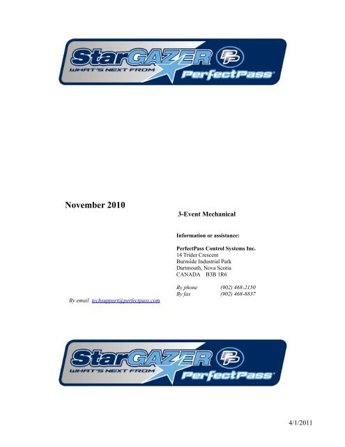
November 2010<br />
3-<strong>Event</strong> Mechanical<br />
Information or assistance:<br />
PerfectPass Control Systems Inc.<br />
14 Trider Crescent<br />
Burnside Industrial Park<br />
Dartmouth, Nova Scotia<br />
CANADA B3B 1R6<br />
By email techsupport@perfectpass.<strong>com</strong><br />
By phone (902) 468-2150<br />
By fax (902) 468-8837<br />
4/1/2011
TABLE OF CONTENTS<br />
Page Number<br />
Section 1 - Getting <strong>Star</strong>ted 1<br />
Initial Setup<br />
Getting Familiar with PerfectPass<br />
Changing Modes<br />
Section 2 - Slalom Mode 3<br />
Selecting Slalom Modes<br />
Calibrating Slalom Speeds<br />
GPS Based Slalom 6<br />
Section 3 - Jump Mode 7<br />
Using Jump Mode<br />
Jump Driving<br />
Additional Information & Settings<br />
New Three Segment Timing 12<br />
Section 4 - Trick Mode 13<br />
Using Trick Mode<br />
Section 5 - RPM Mode 15<br />
Section 6 - Wakeboard Mode 16<br />
Using Wakeboard Mode<br />
Section 7 - Integrated Timing 18<br />
Placing Smart Timers<br />
Placing Magnets<br />
One Magnet Timing<br />
Section 8 - Magnet Test Mode 19<br />
Section 9 - Additional Features 20<br />
Screen Contrast<br />
Name List<br />
System Info<br />
Servo Motor Test 21<br />
Device Test<br />
GPS Info - Clock<br />
Section 10 - Installation 22<br />
Section 11 - GPS Receiver Installation 25<br />
Section 12 - Trouble Shooting/General Information 26<br />
System Reset 27<br />
APPENDIX<br />
All Ball Timing Information<br />
Warning: PerfectPass highly re<strong>com</strong>mends you be<strong>com</strong>e familiar with the operation of your new boat prior to using the speed control. (Leave in<br />
OFF position). Once you are familiar and <strong>com</strong>fortable with the operation and handling of your boat, try the speed control in the different modes<br />
without a skier to familiarize yourself with its operation. If you feel it is not working properly or have questions, leave in the OFF position and<br />
contact PerfectPass or your dealer immediately.<br />
4/1/2011
Section 1. GETTING STARTED<br />
USER’S GUIDE<br />
INITIAL SETUP - The display will guide you through this set up. Read slowly and carefully.<br />
Your new PerfectPass system must now <strong>com</strong>plete a short set up procedure to familiarize itself with your<br />
particular boat and engine. (This may have been performed by your dealer if factory installed)<br />
Step (1) The display will now show [read in MPH ^ = Yes]. It is asking you if you would like the display to operate in<br />
mph. If you do, confirm by pressing the UP key. If you want kph press the DOWN key. (We have selected<br />
mph for illustration purposes)<br />
Step (2) [WAKE Edition ^ = Y] The display will now ask if want the system to be a WakeEdition or a 3-event Edition: For<br />
WakeEdition Press UP, for Three <strong>Event</strong> press DOWN.<br />
Step (3) The display will now move into the Slalom mode, described in the next section.<br />
GENERAL SYSTEM INTERFACE<br />
<br />
<br />
<br />
<br />
The System will always be powered & screen active, even when in the OFF Mode.<br />
Turn Control On or Off while boat is in neutral or at idle is re<strong>com</strong>mended.<br />
Engaging System- Once you select speed, simply throttle up and when the actual speed reaches the set speed,<br />
PerfectPass will take over automatically and you will hear an audible beep.<br />
Disengage System – Simply pull back on the throttle.<br />
BUTTON USE<br />
ON/Off is used to turn control On or Off while boat is at idle or in neutral.<br />
The Menu Button is similar to a mouse, the Menu button moves the cursor around the PerfectPass screen.<br />
Up & down buttons are used to change speeds, settings, etc.<br />
Anytime you see the “^” used in a question such as “Read in MPH ^ = Yes” means press the Up Button “^” to<br />
confirm. The Up Key means Yes.<br />
CHANGING SCREENS / MODES<br />
To change to a different mode, simply press the Menu Button until the Menu Arrow Icon<br />
is highlighted. When highlighted, press the Up Key.<br />
in the upper right hand corner<br />
Menu Arrow<br />
(Highlight and Press Up<br />
to Change Modes)<br />
1
Once you press the Up Key and move from the Slalom Screen, the following screen will appear:<br />
To change modes press the MENU key until the desired mode is highlighted. Press the UP key to go into the highlighted<br />
mode. In this example, you would press Up Key to enter Trick Mode. Press DOWN to go into the Mode’s background<br />
Setting Screens.<br />
DOWN key for Mode settings<br />
UP key to Select Highlighted Mode (Trick)<br />
SUBMENU SCREEN<br />
To enter the SUBMENU press the MENU and UP keys together, on any of the main mode screens.<br />
1. Contrast – To adjust the darkness of the lettering on the screen you can change the contrast. This value can be<br />
adjusted from 0-5 and is saved in the memory. The smaller the number, the brighter the screen will be in bright<br />
sun.<br />
2. User Settings – Enter to change from MPH KPH. See Page 22.<br />
3. Quick List – You can pull or enter a name from the name list here. The full description of the Name List is in<br />
Section 10, Page 21 of the manual.<br />
4. System Info – General system information can be found here. The software version, engine selection, system<br />
voltage and water temperature (not equipped on all boats) can be found here. See Section 10, Page 21.<br />
ADDITIONAL FEATURES for more information on this feature.<br />
5. Device Test – This test allow you to test for proper control of the rope switches and for system troubleshooting of<br />
servo motor. See Section 10, Page 22.<br />
6. GPS Info – For clock and longitude/latitude info, see Section 10, Page 22 for details.<br />
2
Section 2.<br />
SLALOM MODE<br />
SELECTING SLALOM MODE<br />
There are several slalom modes to choose from:<br />
- New Auto/ GPS Mode and GPS Practice Mode<br />
- Classic Slalom (Same as 2007 version)<br />
- CAL BASELINE Mode<br />
To select the Slalom Mode of your choice, simply highlight the Menu Arrow Key in upper right corner and press Up Key.<br />
When SLALOM is highlighted, press the Down Key for different modes.<br />
To select the desired Slalom<br />
mode, highlight the Menu<br />
Arrow and press UP key<br />
UP on<br />
When Slalom is highlight press<br />
DOWN key<br />
DOWN<br />
Choose the desired Slalom<br />
Mode with the MENU key, and<br />
press the UP key to select<br />
There are 3 main Slalom Modes to select from:<br />
1. Calibrate Baseline – Used to initially calibrate baselines<br />
2. Classic Slalom – The “original” DigitalPro Slalom Mode.<br />
3. Auto/GPS - The new GPS enhanced Slalom Mode.<br />
- New GPS Practice Mode.<br />
Each Slalom Speed MUST BE CALIBRATED for accuracy in the CAL BASELINE MODE. Once calibrated, the<br />
calibration settings are transferred automatically to the other modes.<br />
3
CALABRATING BASELINES<br />
Enter the CAL BASELINE Mode to initially set up your baseline RPM settings.<br />
Each official speed that you intend to use (24.9 – 36 mph) must be calibrated for accuracy without a skier using timing<br />
through the course. There is no need to calibrate the lower speeds. (23 mph & lower)<br />
Step. 1<br />
Step. 2<br />
Step. 3<br />
Select Set Speed (Example: 34 mph) and enter weight of crew (Highlight the Slalom heading & press Down<br />
Key).<br />
Drive up and engage system prior to entering course. You will hear the timing start as you pass entrance gate.<br />
Stop boat and review the time on screen (Example 16.90 seconds)<br />
If you have a valid time, highlight the Menu Arrow Icon in upper right hand corner and press the Down<br />
Key to access the “Quick Calibrate Screen”. In this screen, press the Up Key to perform the Calibration.<br />
System will confirm “RPM Baseline & Speedo Calibrated”.<br />
4. Menu Arrow<br />
1. Quick Calibrate<br />
3. Baseline<br />
2. SETPOINT<br />
RPM Adjust<br />
Course Time<br />
Tachomete<br />
r<br />
The system has now been calibrated for 34.2, select a different speed and repeat procedure.<br />
CALIBRATING WITHOUT A COURSE<br />
You can calibrate in open water using: “Capture Mode”. Please see the Important User Info/FAQ<br />
addendum in <strong>Manual</strong>.<br />
4
USING AUTO/GPS MODE<br />
Step.1<br />
Step.2<br />
Step.3<br />
Enter Crew Weight (Highlight Slalom & Press Down Key)<br />
Select Speed (Use Menu Key to highlight speed).<br />
Tow Skier<br />
At the end of the course the full segment time will be on the screen. For mid course or “all buoy”times, press the Down<br />
Key.<br />
KX – This mechanical system retains the KX adjustment so older boats can firm up the control if need be. KX – Normal is<br />
standard, + or ++ will provide a more aggressive response.<br />
PRACTICE MODE<br />
There is a new Practice Mode which is based on the Auto/GPS Mode. In this mode, you can tweak the set speed so you can<br />
train at in-between speeds.<br />
Simply highlight the word Slalom on the main GPS Slalom Screen and press Up Key.<br />
In this mode, you can tweak the speed in small .1 mph increments.<br />
USING CLASSIC MODE) (Non GPS Enhanced)<br />
The PerfectPass Classic Mode is still fully approved by USA WaterSki.<br />
1. RPM Adjust<br />
2. Name/Mode/Crew<br />
3. Menu Arrow<br />
8. KX (Pull)<br />
7. PX (Rope)<br />
4. Speed/SETPOINT<br />
6. Skier Weight<br />
5. Course Times<br />
Tachomete<br />
r<br />
Step.1<br />
Step.2<br />
Step.3<br />
Step.4<br />
Select speed and enter weight of crew. (Highlight slalom heading & press down key).<br />
Enter the Skiers Weight on screen.<br />
Tow skier through course.<br />
At the end of course, review times and if slow or fast, use the RPM Adjust in upper left hand corner to tweak<br />
speed. (ie: More rpm if slow, less if fast)<br />
5
PRACTICE MODE / TIMING METHOD / WT / PREV TIMES<br />
To access these features, highlight Slalom Heading on GPS Slalom Screen & press Up Key.<br />
1. Practice Mode – In this GPS enhanced Mode, you can adjust set speed Up or Down as desired.<br />
2. Here you can switch between Multi Magnet Timing or the new One Magnet Method. (Use Up or Down Key).<br />
3. WT – To enter a Wait Time between skiers for tournament use.<br />
4. Previous Times – To review the times from the last pass.<br />
Use Up or Down Key to change to<br />
Practice Mode < > GPS Slalom.<br />
Tournament Mode<br />
If you press the Up & Down Keys at the same time, you will enter this mode which<br />
simply shows the times in a larger font.<br />
Driving Tip: For the best pull and most accurate times, drive up smoothly and engage system<br />
as far as possible before entering course.<br />
Timing Tip:<br />
On new system start up or after a system reset, the “One Magnet” timing mode<br />
is the default.<br />
6
Section 3. JUMP MODE<br />
USING JUMP MODE<br />
WARNING: (Timing must be used in Jump mode and a proper two segment jump course is required for system to work<br />
properly. Do not use PerfectPass in Jump mode without a proper course, integrated timing and experienced operator.<br />
Because the counter cut pull and cut to the ramp are different, you must have timing activated and running as the boat heads<br />
towards the ramp.<br />
The Jump mode is RPM based and therefore baseline values must be established just as in Slalom mode. Setting the jump<br />
baseline values must be done in a proper two segment jump course. Jump Letter must be set at A for this process.<br />
The Jump mode main screen will appear as follows:<br />
2. Name/Mode/Crew/<br />
New Jumper<br />
1. RPM Adjust<br />
3. Menu Arrow<br />
8. S2 Fine<br />
4. Speed/SETPOINT<br />
7. S2 Percent<br />
6. Jump Letter<br />
5. Course Times<br />
Tachometer<br />
1. RPM Adjust<br />
RPM adjust allows the driver to increase or decrease the overall times (1 st & 2ng segment) by putting in a positive<br />
or negative RPM adjustment.<br />
Example: If the times are running consistently slow on both segments, you could add a value such as +20 rpm and<br />
the speed will be increased. You may wish to do this for a particular jumper (a heavy puller) or for a number of<br />
jumpers if the times are drifting in a certain direction<br />
2. Name/Mode/Crew/New Jumper<br />
This section of the screen displays either the Mode Name or a Skier’s Name pulled from the Name List.<br />
Press UP key to access the Name List:<br />
Name List is discussed in Section 10.<br />
Press DOWN key to access the New Jumper and Crew Weight<br />
Press the UP key to enter a new jumper or<br />
DOWN key to enter or edit the crew<br />
weight. New Jumper is covered below.<br />
7
Enter the Crew Weight in pounds using the<br />
UP and DOWN keys. Press the MENU<br />
key to confirm and continue.<br />
3. Menu Arrow<br />
Press UP key to change modes or mode settings:<br />
This allows you to change modes and<br />
mode settings. The Additional Jump<br />
Settings will be discussed below.<br />
Press DOWN key to Calibrate system:<br />
The calibration screen is described<br />
below in this section.<br />
4. Speed/SETPOINT<br />
The speed readout will turn into the SETPOINT when the engine is below 1500 RPM or the Speed/SETPOINT is<br />
highlighted. When this is highlighted the metric conversion will appear in this area of the screen.<br />
Press UP or DOWN keys to select desired SETPOINT.<br />
5. Course Times<br />
This section of the screen displays the timing information from the last pass. If Jump Letter is set to A and RTB,<br />
the second segment error from Return to Baseline will be displayed after segment errors as seen below:<br />
Tolerance Indicator<br />
= Good Times<br />
= Slow Times<br />
= Fast<br />
Times<br />
1 st and 2 nd Segment Times<br />
1 st and 2 nd Segment Errors<br />
2 nd Segment Error<br />
from Return to<br />
Baseline Times<br />
6. Jump Letter<br />
8
The Jump Letter is a <strong>com</strong>bination of Jumper Weight, Jumper Distance and ability. . This Jump Letter represents<br />
how much throttle will be applied once the Rope Switch is closed as the skier pulls. The higher the Jump Letter<br />
selected the more aggressive the pull will be. If you are unsure what Jump Letter you should use then start by<br />
using the ‘New Jumper’ feature as described below. This will automatically generate a Jump Letter based on your<br />
weight and distance.<br />
7. Second Segment Percent (S2%)<br />
This is a percent of the Jump Letter RPM that is applied once the boat enters the 2 nd segment. Under IWSF and<br />
AWSA rules, the boat is permitted to speed up in the 2 nd segment. The higher the number, the more the boat will<br />
accelerate. A typically value for S2% is +60, the higher the value, the faster the 2 nd segment.<br />
Example: If the 1 st segment times are good, but the 2 nd is a little slow, you would raise the number.<br />
S2 RTB – Works similar to S2%. Used when “Return to Baseline” is selected. Only applicable if skiers are<br />
activating switch and use a Jump Letter of J or higher.<br />
8. Second Segment Fine Adjust (S2 Fine)<br />
This adjustment allows the driver to effectively fine adjust the 2 nd segment only. It <strong>com</strong>es set at 0, which means a<br />
neutral effect. A number such as 30 would increase the 2 nd segment by 30 rpm. Higher number speeds up the<br />
second segment. If skier does not trigger switch or has a letter less than J, S2 fine should be used to speed up<br />
second segment.<br />
Example: A jumper that does not cut and does not fully activate the switch may require extra rpm in the 2 nd<br />
segment to keep the 2 nd segment in tolerance. (In this case, S2 Fine is more effective than S2%).<br />
Entering a New Jumper – To enter a new jumper highlight the NAME/MODE/CREW/NEW JUMPER section of the<br />
screen and press the DOWN key. Then press the UP key to confirm you would like to enter a New Jumper.<br />
You will be asked to enter and answer the following information after which a Jump Letter will be calculated for you and<br />
displayed on the main screen. Move to the next selection by pressing MENU.<br />
Select desired SETPOINT<br />
Enter jumper weight in pounds<br />
Enter typical jumping distance in feet<br />
Toggles between Fast Second Segment<br />
and Return to Baseline<br />
Return to Baseline (RTB) – If you selected Return to Baseline the screen will show to the right of the Jump Letter.<br />
When RTB is selected the boat speed will immediately go to the baseline value as boat enters the second segment. If you<br />
have a skier using the switch with a value of J or higher, you can enter an S2 value which is a % of switch driven RPM. A<br />
setting above 0 will speed up boat in second segment if required to balance times. (This is similar to S2% used when Faster<br />
2nd Segment is selected).<br />
Fast 2 nd Segment – If you selected to run the fast 2 nd segment, the screen will show<br />
to the right of the Jump Letter.<br />
Calibrating RPM Baselines - You can set RPM Baseline values for all of the official jump speeds (28, 29.8, 31.7, 33.6,<br />
and 35.4) or just the ones you use regularly. Let us assume you wish to set up 33.6 mph (54 kph). Enter the SETPOINT of<br />
33.6 mph by pressing the MENU key until the ‘Speed/SETPOINT’ section of the screen is highlighted, then adjust the<br />
SETPOINT to 33.6 = 54K. Set the Jump Letter to A. Now bring the boat smoothly up to the SETPOINT to engage the<br />
system. (The system engages as soon as the default RPM Baseline value is reached, the NAME/MODE section will be<strong>com</strong>e<br />
highlighted, and an audible beep will sound). Enter the jump course and time both segments. As you exit the course the<br />
times will be displayed and then the difference from actuals. The display screen will show the 33.6 mph times. The jump<br />
9
letter is set at A, RTB (return to baseline times are used). An example of this is shown in JUMP TIMING screens shown<br />
earlier in this section.<br />
If the times are not in tolerance or close to actuals then the RPM Baseline values will require adjustment. The easiest way<br />
to do this in Jump mode is to go to Quick Recalibrate by pressing the DOWN key with the<br />
you to the Calibration screen as seen below.<br />
4. Menu Arrow<br />
highlighted. This will bring<br />
1. Quick Calibrate<br />
3. Baseline<br />
2. SETPOINT<br />
Course Time<br />
Tachomete<br />
r<br />
RPM Adjust<br />
Press the UP key on the Quick Calibrate message to recalibrate the baseline based on the times recorded from the last pass.<br />
In this example it is suggesting your RPM Baseline should be increased by 135 rpm. When you perform a Quick Calibrate<br />
the suggested adjust of 135 will be added to the baseline and saved in memory. The system will also calibrate the digital<br />
speedometer if the times are with in the “OK” tolerance.<br />
Now engage system and time boat again. If the times are still not close enough, repeat above steps until accurate. If you<br />
wish to set up RPM Baseline values for other speeds (i.e. 31.7 mph), change the SETPOINT and repeat the above steps.<br />
JUMP DRIVING<br />
WARNING – Using the Jump mode with Jump Switch is for experienced drivers and skiers only. Please read carefully prior to<br />
operating. The pull is very aggressive and designed for tournament water skiers only. You MUST have integrated timing and a proper<br />
jump course for system to operate properly.<br />
Assuming the RPM Baseline values have been accurately set, you are now ready to tow skiers.<br />
First enter your Jump Letter or enter a “New Jumper” as explained above. The Jump Letter can be changed by pressing the<br />
UP or DOWN keys with the Jump Letter highlighted on the screen.<br />
The key to a good pull and good times is to get the correct Jump Letter. If the pull to the ramp is solid and the first segment<br />
time is good, you know the Jump Letter is OK. If the time on the 1 st segment was slow, you will require a higher letter on<br />
the next pass and vice versa. (Once engaged, push handle to full open position to allow PerfectPass room to throttle up<br />
when pulling long distance jumpers).<br />
If the first segment time was good, but the 2 nd was slow, raise the S2%.<br />
Important Note: If the timer is triggered prior to entering the course, it must be reset by pressing the UP key. Failure to<br />
reset will result in an improper pull to the ramp.<br />
ADDITIONAL SETTINGS<br />
Additional Jump Settings are accessed by pressing the UP key on the Main Slalom Screen with the highlighted. Then<br />
press the DOWN key when JUMP is highlighted on the Mode Select Screen. The first three options can be accessed from<br />
the Main Slalom Screen as described above as well as in the Jump Settings Screen.<br />
10
Crew Weight – This setting can also be accessed on the main Slalom Screen as mentioned above or through the Jump<br />
Settings screen. This value should be set to represent the total Crew Weight in pounds in the boat. It is essential this value<br />
be properly setup to ensure you get good times.<br />
Crew Weight Calculator - The system will add the weight of up to 3 individual crewmembers. Simply go to<br />
“Crew Adj” on the list, then press the DOWN and UP keys together, enter the weight of crew member #1, press<br />
MENU and do the same for crew member #2. The system will total the weight automatically.<br />
Calibrate – Press the UP key to enter the Baseline Calibration screen. This can also be accessed by pressing the DOWN<br />
key with the highlighted on the Main Jump Screen.<br />
New Jumper – Details for entering a new jumper are outlined above. This should be used when unsure what Jump Letter<br />
to select.<br />
CT (Counter Cut Time) - The maximum length of time the system will throttle once the skier pulls and closes the switch<br />
on the counter cut. Example: a value of 175 is 1.75 seconds and may be used in a tail wind. In a head wind you may want a<br />
longer pull so you could move it to 200 – 220 (2.0 – 2.2 seconds). The factory default is 190, or 1.9 seconds.<br />
x8u and x8d - These settings were always riding in the software, but were not adjustable values. With the higher<br />
horsepower engines and strong props being produced, these values are available for adjustment if needed for high-end<br />
jumpers.<br />
x8u – Represents the rate of throttle up on counter cut and cut for ramp once switch is activated. The larger the<br />
value, the softer the start will be. In other words, the pull will not be as aggressive on the start, but more gradual.<br />
The smaller the value, the more aggressive it will throttle up as switch closes.<br />
Example: A strong 6 Litre engine may need a larger X8u to avoid a strong initial pull as switch closes.<br />
x8d – Represents the rate of throttle down once skier stops pulling. The higher the value, the slower (softer) the<br />
throttle will return. The lower the value, the more aggressive it will throttle back.<br />
Example: If a boat was not slowing quickly enough in the 2 nd segment, you would lower the value.<br />
Typical values 2008 Promo Boats with DBW PerfectPass<br />
5.7L 6.0L<br />
x8u 85 650<br />
x8d 275 275<br />
One Magnet Timing - In the background settings, you can switch from multi-magnet to one-ball timing. If you select<br />
one- ball in Jump or Slalom, it carries over to the other mode.<br />
Jump Settings<br />
New Times (Faster Second Segment)<br />
Examples for when towing jumpers over 120 Feet.<br />
Jump Settings S2% S2 RTB CT<br />
Ski Nautique Faster 60 – 120 Faster 10 190<br />
MasterCraft Faster 60 – 120 Faster 10 190<br />
Malibu Faster 60 – 120 Slower 5 190<br />
Others Faster 60 – 120 Slower 5 190<br />
Important Tip: Once engaged, the throttle handle should be pushed forward to provide the system with room to throttle<br />
up. For long distance jumpers, it should be moved to full open.<br />
11
Tournament Mode – Jump<br />
If you press the Up & Down Keys together while in jump mode, the new Tournament Mode will appear. The only<br />
difference in this mode is the screen layout, particularly the size of the timing data.<br />
Baselines should be set and established in standard jump mode.<br />
Jump Letter<br />
RPM Adjust<br />
Second Segment<br />
S2%<br />
Times<br />
Effective May 2008, IWSF requires R & L Class Jump <strong>Event</strong>s to run the new three segment timing.<br />
PerfectPass will show this new segment, however, you must select ONE MAGNET METHOD as most<br />
courses will not have a magnet in this new location.<br />
Section 4.<br />
TRICK MODE<br />
12
USING TRICK MODE<br />
The trick mode is controlled via the speed signal from the GPS Receiver. (You simply select the desired speed and go.<br />
RPM values are not used and no other settings are required).<br />
The main Trick screen will appear as:<br />
2. Name/Mode<br />
1. SETPOINT<br />
3. Menu Arrow<br />
Mode<br />
Indicator<br />
Tachometer<br />
Speed<br />
1. SETPOINT<br />
The speed at which would like the boat to engage and control. This number is adjusted in 0.1 mph (0.2 kph)<br />
increments. It can be adjusted while engaged (“on the fly”), or before it is engaged.<br />
2. Name/Mode/Crew<br />
This section of the screen displays either the Mode Name or a Skier’s Name pulled from the Name List.<br />
Press UP key to access the Name List:<br />
Name List is discussed in Section 10.<br />
3. Menu Arrow<br />
Press UP key to change modes or mode settings:<br />
As mentioned above this allows you to<br />
change modes and mode settings.<br />
TRICK DRIVING<br />
Using Trick mode is relatively easy. Turn control ON, select the desired speed and drive smoothly to the SETPOINT so<br />
PerfectPass can seamlessly take over. If you accelerate aggressively past the SETPOINT, it will take the system several<br />
seconds to lock in the speed.<br />
You should keep your hand on the throttle to ensure it does not pull back and disengage the system. If you see the “More<br />
Throttle” on the screen, this indicates the system needs a little more manual throttle.<br />
13
If the skier falls, pull back on the throttle to disengage system. Slowly return to skier and pull them back up again. System<br />
will take over automatically once SETPOINT is reached. Speed changes can be made “on the fly”.<br />
When you are finished with the speed control, go to neutral and press the ON/OFF key.<br />
TRICK SETTINGS<br />
Trick Settings are accessed by pressing the UP key on the Main Trick Screen with the<br />
DOWN key when TRICK is highlighted on the Mode Select Screen.<br />
highlighted. Then press the<br />
Kd – This adjustable parameter controls the “firmness of the Pull”. Higher the number, more aggressive the pull. Normal<br />
range 14 – 28.<br />
14
Section 5.<br />
RPM MODE<br />
USING RPM MODE<br />
In this mode, the screen will appear as follows:<br />
1. SETPOINT<br />
2. Menu Arrow<br />
Mode<br />
Indicator<br />
Tachometer<br />
Speed<br />
Operating in this mode is very similar to using the Wakeboard or Trick modes, except the system is now controlling to an<br />
RPM SETPOINT.<br />
RPM DRIVING<br />
Prior to towing the rider / skier, select the RPM SETPOINT by using the UP or DOWN keys with the SETPOINT<br />
highlighted on the screen. Pull the rider up smoothly and continue to accelerate up to or beyond the RPM SETPOINT so<br />
the system can engage and take control.<br />
Changes can be made to the RPM SETPOINT while the system in engaged (“on the fly”) to fine-tune the RPM you desire.<br />
Note: You cannot enter “Names” in this mode.<br />
15
Section 6. WAKEBOARD MODE<br />
USING WAKEBOARD MODE<br />
This is a speed-based mode using the GPS Data to control similar to the TRICK mode. The Main Wakeboard Screen will<br />
appear as follows:<br />
2. Name/Mode<br />
1. SETPOINT<br />
3. Menu Arrow<br />
Mode<br />
Indicator<br />
Tachometer<br />
Speed<br />
1. SETPOINT<br />
The speed at which would like the boat to engage and control. This number is adjusted in 0.25 mph (0.5 kph)<br />
increments. It can be adjusted while engaged (“on the fly”), or before it is engaged.<br />
2. Name/Mode/Crew<br />
This section of the screen displays either the Mode Name or a Skier’s Name pulled from the Name List.<br />
Press UP key to access the Name List:<br />
Name List is discussed in Section 10.<br />
3. Menu Arrow<br />
Press UP key to change modes or mode settings:<br />
As mentioned above this allows you to<br />
change modes and mode settings.<br />
DRIVING WAKEBOARD<br />
Select the desired SETPOINT by pressing the UP or DOWN keys. Pull the rider up normally and accelerate smoothly up<br />
to or slightly beyond the target speed. Once PerfectPass sees the actual speed reach the SETPOINT it will automatically<br />
take control and will notify you of this with an audible beep. (Top line will be<strong>com</strong>e highlighted during engagement).<br />
16
While in engaged the WakeboardPro should hold a smooth steady speed in a straight course down the lake. The driver<br />
should keep their hand on the throttle for safety, and to prevent it from pulling back on its own which will cause PerfectPass<br />
to disengage.<br />
The key to driving is to smoothly drive to the SETPOINT so the system can seamlessly take control. If you accelerate<br />
aggressively past the SETPOINT it will hunt around for several seconds before settling in. You will hear an audible beep<br />
when the system automatically takes control. If the rider falls, simply pull back on the throttle and the system will<br />
disengage.<br />
To Disengage System: If the rider falls simply slow the boat down. This will disengage speed control. Return to rider<br />
slowly and pull up again. System will once again take over when SETPOINT is reached.<br />
Turns / Over-riding the system: As the boat enters a turn, the engine RPM may increase to keep the craft at the<br />
SETPOINT. If the driver would like less throttle (so the rider does not get whipped) then simply pull back some on the<br />
throttle and help the system maintain a safe speed. As you <strong>com</strong>plete the turn, move the throttle gently forward and the<br />
system will re-take control. (The driver can override the system at any time by pulling back or advancing the throttle).<br />
Wake Surfing in Wakeboard mode is excellent in the 9 – 11 mph range. Prior to using your boat for wake surfing, check<br />
with your boat builder or dealer to confirm it is safe for this sport.<br />
WAKEBOARD SETTINGS<br />
Wakeboard Settings are accessed by pressing the UP key on the Main Wakeboard Screen with the<br />
press the DOWN key when WAKEBOARD is highlighted on the Mode Select Screen.<br />
highlighted. Then<br />
KdW (Pull Characteristic) - KdW can be changed using the UP or DOWN keys with it highlighted on the screen. Higher<br />
values = more aggressive control response. Factory setting is 80. (Example: Heavily loaded boats may need a higher value<br />
to maintain a steady, crisp pull. Try 100– 150). After adjustment, press MENU to proceed. (Maximum re<strong>com</strong>mended<br />
setting 200).<br />
17
Section 7. INTEGRATED TIMING<br />
PLACING SMART TIMERS<br />
The sensor should be placed as close as possible to the outside of the boat. Typically the sensor is beside and under the<br />
passenger seat in a dry location. The Velcro should hold it firmly on the carpet. Place the timer in the direction as indicated<br />
on the Timer label to match the polarity of the magnets. If you are using 2 Smart Timers they should be lined up evenly so<br />
they are across from each other in the boat.<br />
Note: For the jump event and for all buoy timing (ABT) you may require two Smart Timers, one located on each side of<br />
the boat. Both will plug into the Master Module. If using one Smart Timer you may have to move it to the driver’s side<br />
depending on where your magnets are located.<br />
Note: Whether using the Hand Timer or Smart Timer magnetic sensor, they will not operate or register a signal unless the<br />
boat is up to SETPOINT and system has engaged. This feature helps to avoid false triggering.<br />
Note: Smart Timer is designed for tournament skiing under tournament conditions. In other conditions such as lake<br />
cruising it will likely false trigger if you engage the system in Slalom or Jump mode. In this case you may wish to<br />
disconnect the Smart Timer when not in tournament like conditions.<br />
False Triggering - To reduce the chance of false triggering, drive a few miles per hour below the SETPOINT after exiting<br />
the course and during the turning route between passes. If you are not dropping skiers between passes do not fully<br />
accelerate to SETPOINT until you have passed through the boat wakes from the previous pass. (Smart Timer will not<br />
accept signals until speed control is engaged). In the event the timer false triggers outside the course and system is<br />
engaged, press the UP key to clear timer.<br />
One Magnet Timing (Slalom/Jump)<br />
In GPS Slalom Mode, highlight Slalom Heading and press Up Key to access the timing methods.<br />
Here you can switch from the standard One Magnet Method (One Magnet Method is re<strong>com</strong>mended) to the Multi Magnet<br />
Method.<br />
In this format, you only require a magnet at the entrance gate to trigger the trimming. (Total of 2 magnets)<br />
Typically, if you have One Smart Timer installed on the passenger side, you will install the magnets on the passenger<br />
side.<br />
As you enter the course you will hear the timer trigger (beep) and see the time start to scroll on the screen. You will see a<br />
mid course time at ball 3 and then the full course time at end.<br />
To review the “all ball times”, press the Down Key.<br />
Tip: In the event the timer false triggers on a wake before entering course, press the Up Key to clear timer.<br />
(Note: If you are running Slalom in one magnet mode, Jump mode will also run in this mode and vice versa)<br />
18
Section 8. MAGNET TEST MODE<br />
TESTING MAGNETS<br />
This mode allows you to test the timing magnets in the slalom and jump course for field strength and polarity. This mode<br />
uses a set RPM value (approximately 3080 rpm) to control. If you are running “All Ball Timing” or are in the jump mode,<br />
you should check that both of the Smart Timers are detecting properly, to do this you may need to drive the boat beside the<br />
course to test each sensor alone. Your test can and should be done in both directions through the course.<br />
Note: Sitting with engine OFF in this mode will indicate if any of your timers are overly sensitive or if something in the<br />
boat is causing a magnetic signal. With engine ON and boat at idle, the timers may trigger due to alternator noise. On the<br />
fly, you can press “Clear” and <strong>com</strong>plete testing.<br />
The boat is brought up to the set RPM to engage the system and the boat is driven through the course. After engagement<br />
the screen should appear as follows:<br />
Drive a split boat path and note the magnet strength readings. After passing two magnets using 2 Timers the system could<br />
display a message similar to the following:<br />
Magnet<br />
Strength<br />
Mode<br />
1. Menu Arrow<br />
Magnet Count<br />
2. Clear Magnets<br />
Polarity<br />
Timer<br />
Number<br />
Timer Number- indicates the timer which has been triggered (labeled on Master Module “Timer 1” or “Timer 2”).<br />
Polarity - In the above example, MAGNET #0 indicates a correct positive polarity “+” with a good strength of 54 from<br />
Timer 2. Magnet #1 shows a Reversed Magnet with a negative polarity “-“ from Timer 1. A weak reversed magnet may<br />
only display the “REV” without the “-“ sign in front of the strength. NOTE: A very large or strong magnet can saturate the<br />
sensor and cause the “-” message to occur incorrectly. In this case move the sensor towards the middle of the boat by about<br />
16 inches and retest. Your test can and should be done in both directions through the course.<br />
Magnet Count – Indicates the order each time a magnet is detected. Counts from 0 to 7 then scrolls back around to 0.<br />
Magnet Strength – indicates the strength of a particular magnet. Acceptable values for magnetic strength are 30 or greater.<br />
Values below 30 may not produce accurate times. To have extremely accurate times, it is best that all magnets have a<br />
similar strength (usually within 5). You can drive back through in the opposite direction and should see similar readings.<br />
Sometimes you may need to unplug one sensor and test each one separately or run slightly wide and then slightly narrow in<br />
order to separate the sensor readings.<br />
Understanding Magnet Test Results<br />
One or more (not all) magnets are showing a low values or “-“ polarity<br />
-Check the depth of that magnet.<br />
-Check magnet polarity. See ‘Placing Magnets’.<br />
All magnets are showing low values<br />
-Check the depth of that magnet.<br />
-If this course is known to be good, the Smart Timer may be failing.<br />
All magnets are showing “-“ polarity<br />
-Check direction of the Smart Timer. Possibly needs to be reversed.<br />
19
Section 9. ADDITIONAL FEATURES (Menu & UP Keys together)<br />
Additional PerfectPass features are accessed by pressing the MENU & UP keys together from any main screen. The<br />
features available vary depending on the make and model of your boat. If a feature is not present on your PerfectPass then<br />
it is not available on your system. To move to the next feature press the MENU key.<br />
1. SCREEN CONTRAST<br />
You can adjust screen contrast by pressing UP or DOWN Keys. (Setting 0-5). In bright sun, you may have to use<br />
a smaller value to improve visibility.<br />
2. NAME LIST<br />
This version of PerfectPass allows you to store up to eight names and their preferred speed. The Name List can be<br />
accessed by pressing the UP key when the NAME/MODE section is highlighted or by going into the SUBMENU<br />
and selecting the Name List. Once in the Name List press the MENU key to move through the list. With the<br />
desired name highlighted press the UP key to select the name from the list and load their settings or press the<br />
DOWN key to edit the name.<br />
Creating Names – First enter the Name List. Press the MENU key until [NEW ENTRY] is highlighted. Then<br />
press the UP key to enter a new name. The following screen will then appear:<br />
Scroll through the alphabet using UP & DOWN keys, and then press MENU to move to next position. Press the<br />
MENU key to move through the settings. If you are programming a JUMP or SLALOM name there will be<br />
another page of settings to enter.<br />
Deleting/Editing Names – As you scroll through list of names, instead of pressing UP key to select that name,<br />
press the DOWN key to edit or delete.<br />
3. SYSTEM INFO<br />
General system information can be found here. The software version, engine selection, system voltage, system<br />
hours, and water temperature (not equipped on all boats) can be found here.<br />
Version<br />
Engine Selection<br />
Water Temp<br />
Temperature<br />
System Voltage<br />
System Hours<br />
NOTE - System Hour and Water Temperature are only available on limited boats)<br />
4. DEVICE TEST (Rope Switch, Servo Motor) (MENU and UP Key together)<br />
20
Other test features such as Jump Switch Testing, Voltage Supply Testing and Servo Motor Testing are found here<br />
via MENU and UP Key. Test mode or through the SUBMENU. These tests can be performed with or without<br />
engine running. PerfectPass must be switched ON.<br />
Rope Switch Test – This feature allows you to test the rope switch to be used prior to a tournament and will<br />
appear as [ROPE SWITCH TEST]. Pull hard on the rope to close switch and it will change to [ROPE SWITCH<br />
ON] and there will be an audible beep to confirm proper operation. Since it takes 250 pounds of force to trigger a<br />
Slalom Switch, it is very difficult to do. The easiest way to confirm operation is to ski with it and watch the<br />
symbol in the upper right corner. This symbol will turn into when the switch is activated.<br />
Servo Motor Test – After Rope Switch Test, Servo Test will appear as follows:<br />
Servo Motor Voltage Supply– This test will check the 12 V supply attached to the PerfectPass Servo Motor (via<br />
Master Module). Voltage level ranges will be slightly lower if the boat engine is not running.<br />
SrvOFF 13.5 OK– The system powers down the servo motor and measures<br />
the supply voltage level. The voltage with engine running should be in the<br />
range of 13 to 14 V. If the voltage is below 13.0 V, the display will show it as<br />
low (“LO”).<br />
SrvON 12.7 OK– The system turns the servo motor on ands measure the<br />
supply voltage. The voltage should be in the range of 12.5 – 13.5 with engine<br />
running. A reading below 12.1 V will produce a “LO” indication. Press<br />
MENU to continue.<br />
The difference between the voltage readings of these two tests indicates the condition of the power connections. A<br />
difference of more than 1.2 V indicates a potential wiring problem.<br />
Servo Motor Phase Test - The servo motor will slowly rotate and continually check all phase circuits (Green,<br />
Black, Brown, White, and Red). If a circuit is bad or “Open”, the voltage will show as 00 as seen on the black<br />
phase on this example. The brown wire should be checked at the Master Module and at the servo motor white sixpin<br />
connector. If all phases show non-zero the phase test has passed. Press the MENU key to continue.<br />
Servo Motor Rotate Test - This test will continually rotate the servo motor back and forth one full rotation. This<br />
is usefully when tracking intermittent wire faults. Example: ‘Servo Motor Phase Test’ checks OK but throttle<br />
feels “limp” and boat engine is unresponsive after a few minutes of operation.<br />
Reset Servo – This function RESETS the servo to its home position. This does not AUTO-TIGHTEN the servo.<br />
5. USER SETTINGS/ENGINE SELECTION (Tach Signal)<br />
Switching display to Metric (KPH MPH).<br />
6. GPS INFO/CLOCK<br />
Shows latitude and longitude as well as GPS Clock.<br />
Set clock for your<br />
region by pressing<br />
UP or Down Key<br />
The Clock will need to be set for your region of the world.<br />
Indicates GPS locked on<br />
satellite.<br />
21
Section 10. INSTALLATION INSTRUCTIONS<br />
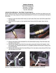
Step 1.<br />
Installation of Servo Motor<br />
Using the two provided hose clamps, loosely mount the servo motor on top of the cooling water hose leading to<br />
drivers side exhaust manifold (starboard side on standard inboard engines). See Figure A. Tighten later after<br />
final positioning (or as specified in any Addendum photos).<br />
Remove ball joint connector from throttle control lever and remove the coupling from end of Morse control /<br />
Teleflex cable. (See Figure B).<br />
Position the servo motor throttle cable in line with the throttle control lever. Ensure the 10/32 locking nut is in<br />
place on Morse control / Teleflex throttle cable. Screw threaded brass hex connector on PerfectPass cable onto<br />
the end of the Morse control throttle cable. (Do not over tighten hex nut). Install L shaped brass throttle adapter<br />
to throttle control lever using identical hole as original ball joint. (L adapter must be able to swivel). Using an<br />
Allen key, tighten L shaped adapter-mounting bolt. (See Figure C). You may find it helps to move the Morse<br />
control lever into gear during installation to allow more clearance. Be sure the washer is next to the brass L-<br />
adapter and not under the nut.<br />
Check and adjust position of servo motor ensuring the motor box cover closes properly and servo throttle cable<br />
is not in contact with any moving parts. Make sure the servo motor cable has 2 or 3 inches of free travel.<br />
Securely tighten hose clamps on servo motor. (Do not “tie wrap” the throttle cable as it must be able to move<br />
freely).<br />
With the throttle in neutral position, adjust brass hex connector if necessary to ensure there is no gap between it<br />
and the end of the servo motor cable (any gap may cause engine to surge up and down in neutral). Adjust and<br />
snugly tighten all parts. (See photos, DO NOT OVER TIGHTEN).<br />
Turn the black servo motor knob in a clockwise position until snug. With throttle in neutral, the linkage should<br />
appear as in Figure C.<br />
Servo Motor / Cable Testing - It is vitally important that the stainless steel cable inside the plastic jacket has<br />
the ability to move freely or the system will not perform properly, may hunt and not settle down. The alignment<br />
of the PerfectPass cable and the boat’s throttle cable should be straight.<br />
Linkage Test - An easy way to confirm proper operation after installation is to perform the following quick<br />
linkage test. With key OFF, push the manual throttle lever to ¾ open position. Then take the black knob on<br />
servo motor and slowly wind the knob in a counter clockwise, then clockwise direction. As you do this, the<br />
engine throttle arm will slowly open and close. This should happen very smoothly and in no place shall the<br />
cable “catch” or “hook” which will cause the servo to hunt. If the cable does “catch”, adjust servo & cable to<br />
eliminate this problem.<br />
If the cable <strong>com</strong>es into any interference with the fuel rail, decorative engine cover or anything that causes this<br />
problem, adjust motor and cable accordingly.<br />
The brass L bracket on the throttle linkage must be able to swivel freely for system to work smoothly.<br />
IMPORTANT: - Make sure all wires are tied away from hot or moving parts and there is adequate<br />
clearance.<br />
- The manual throttle on your boat should operate and feel the same as before the<br />
PerfectPass was installed, or you may have to adjust hex nut.<br />
If you have re-installed a decorative engine cover, with key “OFF” push the throttle down to full open and back to<br />
neutral. At no point should the PerfectPass cable “hook” or “jam”. (Never tie wrap on restrict the PerfectPass<br />
cable from free movement).<br />
22
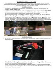
Step 2.<br />
Installation of Master Module<br />
Mount the Master Module under the dash normally on the bulkhead accessible behind and right of the passenger<br />
seat in a dry location. It can also be installed on the left side of driver’s bulkhead. The wires from under the<br />
dash pod can be easily fed across the bulkhead.<br />
Route servo motor power cable from Master Module to servo motor and connect. A wire snake is helpful. (Use<br />
tie wraps to keep cable away from moving parts). Make sure the tips on the plug are facing up towards the top<br />
of the Master Module box.<br />
Step 3.<br />
Mount Dash Display<br />
Remove the right speedometer and install the In Dash PerfectPass Display and connect into Master Module.<br />
(If there is a speedo tube on back, it can be plugged using a golf tee).<br />
If you have the External Display, install using supplied mounting post to the right of dash next to wind screen.<br />
In the event you have 5” gauges, generally the PerfectPass 5” display replaces the tachometer.<br />
(On 5” gauges, refer to specific instructions sent with gauge).<br />
Step 4.<br />
Connect Power Wire<br />
Depending on the boat and model, there are a number of ways to connect to a switched (12 volt) power source.<br />
1. On boats with traditional analogue gauges and posts on back of tachometer, there is a 12 volt (+) post often<br />
marked (IGN) which is an easy connection to the purple wire. The black wire end can attach to the ground<br />
(-) post marked (GND).<br />
2. On boats with Borg Warner gauges with no posts, attach the PerfectPass purple power wire to the purple<br />
wire leading to the ignition terminal. The black wire can be securely grounded to the grounding bar or<br />
other suitable ground location.<br />
3. 2000 – 2005 Nautiques – There is a main wiring harness and large white plug located behind the dash<br />
pod. Connected to this plug is a purple wire carrying the switched 12 volts and a black wire which is a<br />
suitable ground connection.<br />
4. 2002 – 2005 MasterCraft – Power, RPM and Paddle Wheel speed is all located in the special plug and<br />
play harness supplied with each system. The MasterCraft supplied white connector is on every boat<br />
specifically for PerfectPass. You may have to remove the driver’s foot panel to locate this connector in the<br />
boat’s wiring harness.<br />
5. 2005 Malibu – The plug & play harness will provide RPM, Power and Speed signal.<br />
Step 5.<br />
RPM Cable Installation<br />
This connection will depend on the brand and year of boat you own.<br />
(1) Standard Installation (Older boats and boats with traditional Analogue gauges with Posts on back)<br />
The Gray wire with ring terminal can be easily attached to the “SEND” post on back of tachometer. This<br />
Gray wires picks up the raw engine rpm from this post. The Black wire ring terminal can be attached to<br />
any suitable ground, including the ground post on the tachometer. (If there is not a post, connect to the<br />
solid gray wire <strong>com</strong>ing from the tachometer).<br />
(2) 2002 - 2005 MasterCraft – The custom wiring harness supplied by PerfectPass allows for plug<br />
& play for RPM and Power.<br />
23
(3) 1998- 2004 Malibu (Borg Warner Gauge System)<br />
In behind the dash pod on most models, Malibu has left a Gray (RPM) wire that terminates at a large<br />
female spade connector. If you can locate this, you can simply attach the Gray wire on the rpm sensor<br />
cable to this connector.<br />
Alternatively, you can locate the solid gray wire in the main wiring harness that leads into the Borg<br />
Warner control box under the dash. Use a blue “Tee Tap” connector to connect to this gray wire. You can<br />
then attach the gray rpm sensor wire to this using a push on spade connector. The black wire can be<br />
securely connected to any suitable ground.<br />
LS-1 On this engine (pre 2002 only), you only connect the Black wire on the RPM Sensor cable to the<br />
Gray wire leading to the Borg Warner control box. (Same as LT-R MasterCraft). The gray RPM sensor<br />
wire is left un-connected.<br />
2005 Malibu - See Plug & Play Harness.<br />
(4) 1999 – 2001 MasterCraft, 2000 Supra, 2000-2002 Infinity (All Other Brands Using Borg Warner<br />
Gauges)<br />
TBI & Multi Port Engines (except LT-R) – Locate the solid gray wire in the main wiring harness that<br />
leads from the engine into the Borg Warner control box under the dash. This solid gray wire carries the<br />
raw engine rpm. Use a blue “Tee Tap” connector to connect to this gray wire. You can then attach the<br />
gray wire on the rpm sensor to this using a push on spade connector. The black wire can be securely<br />
connected to any suitable ground.<br />
LT-R / LT-1 - On this engine the Gray wire lead on the PerfectPass RPM Sensor cable is not used and<br />
can be taped off. The separate Black wire end must be connected to the Gray wire located in the main<br />
wiring harness leading into the Borg Warner MDC Control box. It is on the engine side of the box that<br />
the raw rpm is located. You can attach a blue “Tee Tap” connector to this Gray wire, and attach the RPM<br />
sensor cable end to this “Tee Tap” using a supplied spade connector.<br />
(5) 2000 – 2002 Nautiques<br />
Same as standard #1 above, except the rpm signal can be picked from the Gray wire <strong>com</strong>ing from the<br />
back of the tachometer.<br />
(6) 2003 - 2005 Nautiques<br />
Located behind the dash pod is a large wiring harness with a large white plug. The Gray wire in this plug<br />
carries the raw rpm of the engine and has been brought to the pod solely for the PerfectPass system. This<br />
gray wire is not connected to any gauge. Use a blue “Tee Tap” connector or other splice method to attach<br />
the Gray wire on the PerfectPass rpm sensor cable to this Gray wire in the harness. The Black wire<br />
(ground) on the RPM Sensor cable can be attached to the black wire in this same boat harness.<br />
Step 6.<br />
Step 7.<br />
If you have a Smart Timer Magnetic Sensor connected into Timer 1 plug. The Smart Timer should be mounted<br />
on the floor, along the outside wall of the boat, generally under or beside passenger seat. With the arrow on the<br />
Smart Timer pointing forward. (If you have two Smart Timers, install the second one on floor beside driver seat<br />
along outside wall). If you do not have magnets in your course, connect the hand timer into “Timer 1” port so<br />
you can time manually. Only connect Smart Timer when you have magnets.<br />
Optional <strong>Manual</strong> “Hand Timer”. If you do not have magnets in your course, connect into “Timer 1”. If you<br />
have a Smart Timer, do not connect hand timer.<br />
Your manual throttle should act and feel just the same as before PerfectPass was installed. If it does not feel<br />
normal, inspect throttle and linkage connection, particularly the brass hex nut adjustment.<br />
For assistance call (902) 468-2150.<br />
24
Section 11. GPS RECEIVER - INSTALLATION INSTRUCTIONS<br />
Installation: The GPS Receiver can be installed on the dash board looking up through the wind<br />
screen. As long as the receiver has a clear unobstructed view of the sky, it will work properly, even if<br />
sitting at an angle to the sky.<br />
(It can also be installed under the dash looking up through the fiberglass. In this case you will need to<br />
move the Velcro to the top of the GPS Puck or use a 2-sided industrial strength tape. The puck must be<br />
mounted with top looking up to the sky).<br />
On a new system, after connection and initial power up it will take up to 10 minutes for the GPS<br />
Receiver to find its new location. Once a proper fix has been made, GPS will appear in the top left of<br />
screen. (If after 10 minutes you do not see GPS, turn key off and back on and wait a few more<br />
minutes).<br />
Until a fix is made, it will appear as “No GPS Fix”. If you see “No GPS Data” on screen, then the<br />
system does not see the Receiver connected. (Check plug in connection).<br />
WARNING: ONLY connect into Master Module in port marked “GPS” or the Receiver will<br />
be<strong>com</strong>e damaged.<br />
25
Section 12. TROUBLE SHOOTING / GENERAL INFORMATION<br />
Detailed Trouble Shooting documents and videos can be found on line at www.perfectpass.<strong>com</strong> .<br />
See Support, “Trouble shooting”.<br />
You can learn a lot from just turning on key and watching system start up. Every time PerfectPass is powered you will see<br />
the back light in Display glow green followed by a beep as the screen be<strong>com</strong>es active. When the Master Module sees a<br />
solid 12 volts +, the Intel processor starts which puts the data on screen and the servo motor will perform its “auto tighten”<br />
check.<br />
A. NOT CONTROLLING<br />
Servo Motor “Auto tighten” Test<br />
Check: To confirm proper operation of the 4 phase servo motor, perform the following test. With key OFF, check to<br />
see if servo motor can be easily turned and that set screw in knob is snug. (It should turn freely, if not the motor<br />
may be seized) Turn knob in clockwise direction until snug, and then turn it back counter clockwise one full turn.<br />
Now turn key ON and servo should perform its “auto tighten” function and wind in the cable (approximately ¾ of a<br />
turn). (Every time system is powered, it will do an “auto tighten” which confirms all electrical phases are OK).<br />
Ideally, you should hold knob gently during “auto tighten” test to put a little extra load on the motor to check the<br />
connections.<br />
Remember the servo motor will run very hot, particularly the gold resistor.<br />
If motor does not wind in or just vibrates, then an electrical connection is likely bad. Unplug both connectors at<br />
servomotor and closely inspect the crimps and wiring. Gently pull on each wire to make sure the wire is securely<br />
crimped. Also check the connectors on the gray servo power cable at both ends (See servo testing in addendum for<br />
detailed testing).<br />
If this test is OK, do a “Linkage Test” as described in section B.<br />
B. Linkage Test - With key OFF, push the manual throttle open to ¾ position. Then take the black knob on servo motor<br />
and slowly wind the knob in a counter clockwise direction, then in a clockwise direction. As you do this, the throttle<br />
will slowly open and close with each step of the motor. In no place should the cable catch or hook as this will cause<br />
the system to surge. If the cable <strong>com</strong>es into contact with any part, fuel rail, cross over pipe or decorative engine<br />
cover, adjust cable and servo as required. (The cable should have a nice smooth bend and be in good alignment with<br />
the throttle connection. If you feel the cable is too long, contact PerfectPass)<br />
The brass L adapter should freely swivel as the throttle opens & closes.<br />
(If your boat has a plastic decorative engine shroud, you may wish to remove it temporarily and see if the problem<br />
disappears).<br />
With key OFF, push manual throttle to full open and back to neutral. Does PerfectPass throttle cable move forward<br />
and back freely without jamming or rubbing against cover, fuel rails, etc<br />
C. System surging in neutral – Check gap between the PerfectPass cable & the Morse control / Teleflex cable. There<br />
should be No Gap. (See photo C in instruction manual).<br />
D. System accelerates past set point – If the system accelerates past the set point and is very slow to work back to the<br />
set speed, the engine throttle return spring may be weak. PerfectPass can open the throttle, but depends on the engine<br />
return spring to bring it back towards neutral. A spring can be easily added. It may also be a throttle cable /<br />
mechanical problem. See Linkage Test, Section B above.<br />
On Water Test – To confirm this, drive the boat carefully with engine cover open. Set speed at a lower setting (i.e.<br />
20 mph) and have driver engage system and press throttle up to 25 MPH. As boat speed exceeds 20 mph, the servo<br />
should turn counter clockwise to let out cable and slow engine. If servo counter rotates, the return spring should pull<br />
throttle back towards neutral. If servo rotates but boat does not slow, the return spring is not pulling or something is<br />
preventing the throttle or cable from moving.<br />
E. No RPM tachometer reading – If the display tachometer reading is 00, check to make sure rpm sensor is plugged<br />
into the correct port on Master Module. Check connections of rpm sensor. (Check installation as per instructions).<br />
26
F. Blown Fuse (5 amp, 1.25 inch fuse)<br />
The most <strong>com</strong>mon reason a fuse will blow is if the red wire in the servo power cable is grounded or shorted. Inspect<br />
the wire for any breaks, pinches or failure especially near the gold resistor on the servo motor.<br />
G. System Reset – If you would like to reset the entire system to original factory specifications, you can do so by<br />
pressing & holding the ON/OFF & MENU Keys together as you power up the system. After about 5 seconds<br />
the display will show [System Reset ^ = Y]. Press the UP key to continue with a reset.<br />
The next question will be whether you wish to reset all your baseline rpm values. [Reset RPM @ ^ = Y] If you are<br />
happy with your baseline values, press the DOWN key and your settings will be maintained. On some systems, you<br />
will be asked to select the engine in your boat. It will then ask if you wish to run in just wakeboard modes<br />
[WAKBD ONLY ^=Y].<br />
H. Change Display from MPH to KPH/Wakeboard only – Perform a “System Reset”.<br />
I. Run in Wakeboard only Mode/Three <strong>Event</strong> Menu – To run in just wakeboard modes or to return to the full event<br />
menu see (I) above.<br />
J. Display is Hard to Read – Adjust contrast.<br />
For more Trouble Shooting details, go to: www.perfectpass.<strong>com</strong> . Click on “Support” and then<br />
go to “Trouble Shooting”. Once there you can choose your boat details and bring up the<br />
appropriate file containing the requested information to assist you.<br />
27
APPENDIX<br />
PerfectPass All Buoy Timing Version 4 IWSF Approved 2001<br />
The All Buoy Timing Method (ABT) eliminates the need for a fall button. In Tournament Use, after a skier falls or misses<br />
during a pass, the boat is timed to the next set of boat gates. Because the boat travels only a relatively short distance before<br />
the time is measured, the boat speed does not change significantly. Thus the time is an accurate measure of the speed of the<br />
boat while pulling the skier.<br />
If the skier runs a full pass, the full course time is used to determine if the boat speed was within tolerance. For scores less<br />
than six, a chart showing the timing tolerances for each buoy score is used. This method uses the cumulative time from the<br />
gates up to the last ball scored. With this approach, only one segment time is required.<br />
After each pass, the PerfectPass system briefly displays the Full Course Time and then the two separate segments as in this<br />
34.2 mph example. [ 0.0 16.95 OK ] then [ 7.13 9.82 OK ] If the score was less than six, then the ABT sub-menu<br />
is entered via the Down Key. The times are displayed in pairs preceded by the score identification and a colon. (Press any<br />
key to take you to the next set of scores). For example: if the score were four and a quarter, you would scroll through the<br />
ABT times until the 4 ID is found which would appear as: “ 4: 12.50 5: 15.19 ” The time of 12.50 would be called in. For<br />
a score of one and a half the display showing “ 0: 1.77 1: 4.45 ” is used and only the 4.45 time is reported. All of the<br />
existing rules for optional and mandatory rerides are applied to the ABT times. (The guide is to always refer to the time<br />
segment corresponding to the score. Example: If the score starts with a 4 you look at the time following the 4 and call in<br />
that time only.<br />
Magnets: A minimum of eight magnets and two Smart Timers are required to run ABT, a course with ball one magnets had<br />
eight magnets already, two are on the entrance and exit gates and two Smart Timers are required for the jump event, so for<br />
many sites the equipment necessary to use ABT already exists.<br />
(Check with our website at www.perfectpass.<strong>com</strong> for more details).<br />
PerfectPass All Buoy Timing<br />
36mph/58kph IWSF approved method 4<br />
score score id. fast in actual slow in<br />
0 to 0.5 0: 1.64 1.68 1.71<br />
1 to 1.5 1: 4.15 4.22 4.28<br />
2 to 2.5 2: 6.67 6.77 6.84<br />
3 to 3.5 3: 9.20 9.31 9.41<br />
4 to 4.5 4: 11.73 11.86 11.97<br />
5 to 5.5 5: 14.25 14.40 14.53<br />
6 16.00 16.08 16.16<br />
PerfectPass All Buoy Timing<br />
34.2mph/55kph IWSF approved method 4<br />
score score id. fast in actual slow in<br />
0 to 0.5 0: 1.73 1.77 1.80<br />
1 to 1.5 1: 4.37 4.45 4.51<br />
2 to 2.5 2: 7.03 7.13 7.23<br />
3 to 3.5 3: 9.69 9.82 9.93<br />
4 to 4.5 4: 12.35 12.50 12.64<br />
5 to 5.5 5: 15.02 15.19 15.34<br />
6 16.86 16.95 17.04
YOU MUST READ THIS!<br />
WARNING<br />
RELEASE OF LIABILITY – ASSUMPTION OF RISK<br />
IMPORTANT<br />
(Detach, sign and mail immediately)<br />
The PerfectPass Speed Control device is a high performance mechanism designed solely for use with<br />
<strong>com</strong>petitive water ski and wakeboard boats operating under ideal, calm conditions utilizing a spotter<br />
and all other safety crew and requirements of tournament water skiing. The PerfectPass Speed Control<br />
device should not be used for any other purpose or under any other conditions.<br />
YOUR USE OF YOUR PERFECTPASS SPEED CONTROL DEVICE IS CONDITIONAL<br />
UPON YOU ASSUMING ALL RISKS, LOSSES AND DANGERS RELATING TO USE OF<br />
THIS DEVICE.<br />
Both purchaser and/or anyone utilizing the PerfectPass Speed Control device acknowledges that their<br />
purchase and or use of this device is conditional upon them releasing and forever discharging<br />
PerfectPass Speed Control Systems Inc., its directors, officers, employees, agents and/or dealers, their<br />
heirs, and assigns from any and all liability for personal injury or property loss and from any other<br />
claims, demands, losses or causes of action, whether occurring prior to, during, or subsequent to or<br />
directly or indirectly connected with the use of the PerfectPass Speed Control device, and whether<br />
caused by any persons negligence or otherwise.<br />
The PerfectPass release of liability, and warranty agreement shall be interpreted in accordance with the<br />
laws of the Province of Nova Scotia, Canada, and IT IS FURTHER AGREED that any legal<br />
proceedings that either directly or indirectly relate to the PerfectPass Speed Control device shall be<br />
conducted within the Province of Nova Scotia, Canada, regardless of where arising.<br />
The purchaser hereby agrees to inform any subsequent purchasers or anyone using the PerfectPass<br />
Speed Control device, of the conditions of this Release of Liability, Assumption of Risk Agreement. It<br />
is agreed that there shall be absolutely no alterations to this agreement whether by implication or<br />
otherwise.<br />
__________________________________________________<br />
Purchaser Signature<br />
__________________________________________<br />
Address<br />
__________________________________________<br />
__________________________________________<br />
Name (Please Print)<br />
___________________________________<br />
Date<br />
_____________________________<br />
Serial Number (found on Master Control Module)<br />
(Must be signed to affect valid purchase and activate warranty agreement, detach and mail immediately to PerfectPass<br />
Control Systems Inc., 14 Trider Crescent Dartmouth, Nova Scotia, B3B 1R6, Canada).
LIMITED WARRANTY<br />
During the first 12 months from date of original retail purchase, any PerfectPass <strong>com</strong>ponent that fails<br />
due to defects in materials or workmanship will be repaired or replaced at the option of PerfectPass at<br />
no charge.<br />
All warranty claims must be authorized in advance and a Return Authorization (R/A #) issued. All<br />
packages, correspondence, documents and packing slips must reference this R/A #.<br />
Warranty excludes <strong>com</strong>ponents damaged my improper installation or improper use of boat. Servo<br />
Motors are water resistant, but not water proof. Servo motors may be<strong>com</strong>e damaged if excess water is<br />
run in a boats bilge and this may void warranty. Ensure your boat is properly “bilged” prior to<br />
operating.<br />
Warranty Service:<br />
1. If your PerfectPass was factory installed, any warranty issues should be directed to your<br />
authorized dealer. PerfectPass encourages all customers to contact us prior to visiting your<br />
dealer for “technical support” as many issues may be easily handled direct with customer.<br />
2. If your PerfectPass was purchased and installed by a dealer you may contact your dealer direct<br />
or initiate a warranty claim with PerfectPass.<br />
3. If your PerfectPass was purchased directly from the Company, contact us at the number below.<br />
Warranty Service / Technical Support<br />
PerfectPass Control Systems Inc.<br />
14 Trider Crescent<br />
Dartmouth, Nova Scotia<br />
CANADA B3B 1R6<br />
(902) 468-2150<br />
(Hours: Monday to Friday 8:00 am – 4:00 pm EST)