
You also want an ePaper? Increase the reach of your titles
YUMPU automatically turns print PDFs into web optimized ePapers that Google loves.
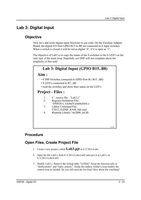
<strong>Lab</strong> 3: Digital Input<br />
<strong>Lab</strong> 3: Digital Input<br />
Objective<br />
Now let’s add some digital input functions to our code. On the Zwickau Adapter<br />
Board, the digital I/O lines GPIO-B15 to B8 are connected to 8 input switches.<br />
When a switch is closed it will be red as digital ‘0’, if it is open as ‘1’.<br />
The objective of <strong>Lab</strong>3 is to copy the status of the 8 switches to the 8 LED’s as the<br />
only task of the main loop. Hopefully our DSP will not complain about the<br />
simplicity of this task!<br />
<strong>Lab</strong> 3: Digital Input (GPIO B15..B8)<br />
Aim :<br />
• 8 DIP-Switches connected to GPIO-Port B ( B15...B8)<br />
• 8 LED‘s connected to B7...B0<br />
• read the switches and show their status on the LED’s<br />
Project - Files :<br />
1. C - source file: “<strong>Lab</strong>3.c”<br />
2. Register Definition File:<br />
“DSP281x_GlobalVariableDefs.c<br />
3. Linker Command File :<br />
F2812_EzDSP_RAM_lnk.cmd<br />
4. Runtime Library “rts2800_ml.lib<br />
3 - 27<br />
Procedure<br />
Open Files, Create Project File<br />
1. Create a new project, called <strong>Lab</strong>3.pjt in E:\C281x\<strong>Lab</strong>s.<br />
2. Open the file <strong>Lab</strong>2.c from E:\C281x\<strong>Lab</strong>s\<strong>Lab</strong>2 and save it as <strong>Lab</strong>3.c in<br />
E:\C281x\<strong>Lab</strong>s\<strong>Lab</strong>3.<br />
3. Modify <strong>Lab</strong>3.c. Remove the lookup table “LED[8]”. Keep the function calls to<br />
“InitSystem()” and “Gpio_select()”. Inside the endless while(1)-loop modify the<br />
control loop as needed. Do you still need the for-loop How about the watchdog<br />
DSP28 - Digital I/O 3 - 23
<strong>Lab</strong> 3: Digital Input<br />
Remember, we served the watchdog inside “delay_function()” – it would be unwise<br />
to remove this function call from our control loop!<br />
4. Add the source code file to your project:<br />
• <strong>Lab</strong>3.c<br />
5. From C:\tidcs\c28\dsp281x\v100\DSP281x_headers\source add:<br />
• DSP281x_GlobalVariableDefs.c<br />
From C:\tidcs\c28\dsp281x\v100\DSP281x_common\cmd add:<br />
• F2812_EzDSP_RAM_lnk.cmd<br />
From C:\tidcs\c28\dsp281x\v100\DSP281x_headers\cmd add:<br />
• F2812_Headers_nonBIOS.cmd<br />
From C:\ti\c2000\cgtoolslib add:<br />
• rts2800_ml.lib<br />
Project Build Options<br />
6. We need to setup the search path to include the peripheral register header files. Click:<br />
Project Build Options<br />
Select the Compiler tab. In the preprocessor Category, find the Include Search<br />
Path (-i) box and enter:<br />
C:\tidcs\C28\dsp281x\v100\DSP281x_headers\include;..\include<br />
7. Setup the stack size: Inside Build Options select the Linker tab and enter in the Stack<br />
Size (-stack) box:<br />
400<br />
Close the Build Options Menu by Clicking .<br />
Build and Load<br />
8. Click the “Rebuild All” button or perform:<br />
Project Build<br />
3 - 24 DSP28 - Digital I/O
<strong>Lab</strong> 3: Digital Input<br />
and watch the tools run in the build window. If you get errors or warnings debug as<br />
necessary.<br />
9. Load the output file down to the DSP Click:<br />
File Load Program and choose the desired output file.<br />
Test<br />
10. Reset the DSP by clicking on:<br />
Debug Reset CPU<br />
Debug Restart<br />
followed by<br />
11. Run the program until the first line of your C-code by clicking:<br />
Debug Go main.<br />
12. Start the code<br />
Debug Run<br />
and test the operation of your code. When you change the status of the switchline<br />
you should see the new value immediately shown at the LED’s.<br />
If not, your modification of the code (Step 3 of the procedure) was not correct. In<br />
this case try to find out why by using the debug tools that you’ve learned about in<br />
<strong>Lab</strong>1 (Breakpoint, Step, Watch Variables…).<br />
DSP28 - Digital I/O 3 - 25
<strong>Lab</strong> 3A: Digital Input + Output<br />
<strong>Lab</strong> 3A: Digital Input + Output<br />
Objective<br />
Now let’s combine <strong>Lab</strong>3 and <strong>Lab</strong>2! That means I’d like you to control the speed<br />
of your “Knight Rider” (<strong>Lab</strong>2) depending on the status of the input switches.<br />
Question: What’s the minimum / maximum value that can be produced by the 8<br />
input switches Use the answer to calculate the length of function “delay_loop()”<br />
depending on the input from GPIO B15...B8.<br />
<strong>Lab</strong> 3A<br />
“Knight - Rider” plus frequency control :<br />
• modify <strong>Lab</strong> 2 :<br />
• read the input switches ( B15-B8 )<br />
• modify the frequency of the ‘running light’<br />
(B7-B0) subject to the status of the input<br />
switches, e.g. between 10sec and 0.01 sec per<br />
step of the LED-sequence<br />
• enable the watchdog timer !<br />
• Verify that , ones your program is in the main<br />
loop, the watchdog causes a reset periodically.<br />
3 - 28<br />
Procedure<br />
Create Project File<br />
1. Create a new project, called <strong>Lab</strong>3A.pjt in E:\C281x\<strong>Lab</strong>s.<br />
2. Open the file <strong>Lab</strong>2.c from E:\C281x\<strong>Lab</strong>s\<strong>Lab</strong>2 and save it as <strong>Lab</strong>3A.c in<br />
E:\C281x\<strong>Lab</strong>s\<strong>Lab</strong>3A.<br />
3. Add the source code file to your project:<br />
• <strong>Lab</strong>3A.c<br />
4. From C:\tidcs\c28\dsp281x\v100\DSP281x_headers\source add:<br />
• DSP281x_GlobalVariableDefs.c<br />
3 - 26 DSP28 - Digital I/O
<strong>Lab</strong> 3A: Digital Input + Output<br />
From C:\tidcs\c28\dsp281x\v100\DSP281x_common\cmd add:<br />
• F2812_EzDSP_RAM_lnk.cmd<br />
From C:\tidcs\c28\dsp281x\v100\DSP281x_headers\cmd add:<br />
• F2812_Headers_nonBIOS.cmd<br />
From C:\ti\c2000\cgtoolslib add:<br />
• rts2800_ml.lib<br />
Setup Build Options<br />
5. We need to setup the search path to include the peripheral register header files. Click:<br />
Project Build Options<br />
Select the Compiler tab. In the preprocessor Category, find the Include Search<br />
Path (-i) box and enter:<br />
C:\tidcs\C28\dsp281x\v100\DSP281x_headers\include;..\include<br />
6. Setup the stack size: Inside Build Options select the Linker tab and enter in the Stack<br />
Size (-stack) box:<br />
400<br />
Close the Build Options Menu by Clicking .<br />
Modify <strong>Lab</strong>3A.C<br />
7. Modify the run time of function “delay_loop”. The input parameter of this function<br />
defines the run time of the software delay loop. All you have to do is to adjust the<br />
actual parameter using the GPIO-input’s B15…B8.<br />
8. The best position to update the parameter for the delay loop time is inside the endless<br />
loop of main, between two steps of the “Knight Rider” sequence.<br />
DSP28 - Digital I/O 3 - 27
<strong>Lab</strong> 3A: Digital Input + Output<br />
<strong>Lab</strong> 3A (cont.)<br />
Serve the watchdog :<br />
• do not disable the watchdog timer !<br />
• Inside the main-loop execute the watchdogreset<br />
instructions (WDKEY) to prevent the<br />
watchdog timer from overflow.<br />
• Place the software-delay in a function and<br />
<strong>experiment</strong> with different delay period’s.<br />
What is the period when the watchdog-timer<br />
does reset the DSP <br />
3 - 29<br />
9. Remember, it is always good practice to work with an enabled watchdog! Eventually<br />
for a large parameter for the period of delay_loop() you will have to adjust your<br />
watchdog good key sequence instructions to prevent the watchdog from causing a<br />
RESET.<br />
Build, Load and Test<br />
10. Build, Load and Test as you’ve done in previous exercises.<br />
3 - 28 DSP28 - Digital I/O
<strong>Lab</strong> 3B: Start / Stop Option<br />
<strong>Lab</strong> 3B: Start / Stop Option<br />
Objective<br />
A last improvement of our <strong>Lab</strong> is to add a START/STOP option to it. The Zwickau<br />
adapter board has two momentary push buttons connected to GPIO-D1 and GPIO-D6. If a<br />
button is pushed, the input line reads ‘0’; if it is not pushed it reads ‘1’. The objective is<br />
now to use D1 as a start button to start the ‘Knight Rider’ sequence and D6 to stop it.<br />
• use <strong>Lab</strong> 2 to start:<br />
<strong>Lab</strong> 3B<br />
Add start/stop control:<br />
• GPIO-D1 and D6 are connected to two pushbuttons.<br />
If they are pushed, the input level<br />
reads 0, if released 1.<br />
• Use D1 to start the LED “Knight-rider” and<br />
D6 to halt it. If D1 is pushed again the<br />
sequence should continue again.<br />
• To do so, you also need to add the instructions<br />
to initialise GPIO-D<br />
3 - 30<br />
Procedure<br />
Create Project File<br />
1. Create a new project, called <strong>Lab</strong>3B.pjt in E:\C281x\<strong>Lab</strong>s.<br />
2. Open the file <strong>Lab</strong>3A.c from E:\C281x\<strong>Lab</strong>s\<strong>Lab</strong>3A and save it as <strong>Lab</strong>3B.c in<br />
E:\C281x\<strong>Lab</strong>s\<strong>Lab</strong>3B.<br />
3. Add the source code file to your project:<br />
• <strong>Lab</strong>3B.c<br />
DSP28 - Digital I/O 3 - 29
<strong>Lab</strong> 3B: Start / Stop Option<br />
4. From C:\tidcs\c28\dsp281x\v100\DSP281x_headers\source add:<br />
• DSP281x_GlobalVariableDefs.c<br />
From C:\tidcs\c28\dsp281x\v100\DSP281x_common\cmd add:<br />
• F2812_EzDSP_RAM_lnk.cmd<br />
From C:\tidcs\c28\dsp281x\v100\DSP281x_headers\cmd add:<br />
• F2812_Headers_nonBIOS.cmd<br />
From C:\ti\c2000\cgtoolslib add:<br />
• rts2800_ml.lib<br />
Setup Build Options<br />
5. Project Build Options<br />
Select the Compiler tab. In the preprocessor Category, find the Include Search Path (-<br />
i) box and enter:<br />
C:\tidcs\C28\dsp281x\v100\DSP281x_headers\include;..\include<br />
6. Setup the stack size: Inside Build Options select the Linker tab and enter in<br />
the Stack Size (-stack) box: 400<br />
Close the Build Options Menu by Clicking .<br />
Modify <strong>Lab</strong>3B.C<br />
7. Take into account to modify the endless while(1) loop of main. The for-loop should<br />
run after D1 is pushed and freeze when D6 is pushed. With the next D1 the procedure<br />
should resume from its frozen status.<br />
Build, Load and Test<br />
8. Build, Load and Test as you’ve done in previous exercises.<br />
3 - 30 DSP28 - Digital I/O