Download - Buderus
Download - Buderus
Download - Buderus

You also want an ePaper? Increase the reach of your titles
YUMPU automatically turns print PDFs into web optimized ePapers that Google loves.
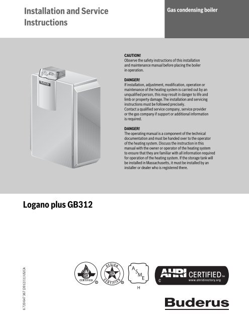
Installation and Service<br />
Instructions<br />
Gas condensing boiler<br />
CAUTION!<br />
Observe the safety instructions of this installation<br />
and maintenance manual before placing the boiler<br />
in operation.<br />
DANGER!<br />
If installation, adjustment, modification, operation or<br />
maintenance of the heating system is carried out by an<br />
unqualified person, this may result in danger to life and<br />
limb or property damage.The installation and servicing<br />
instructions must be followed precisely.<br />
Contact a qualified service company, service provider<br />
or the gas company if support or additional information<br />
is required.<br />
DANGER!<br />
The operating manual is a component of the technical<br />
documentation and must be handed over to the operator<br />
of the heating system. Discuss the instruction in this<br />
manual with the owner or operator of the heating system<br />
to ensure that they are familiar with all information required<br />
for operation of the heating system. If the storage tank will<br />
be installed in Massachusetts, it must be installed by an<br />
installer or dealer who is registered there.<br />
Logano plus GB312<br />
6 720 647 367 (2012/11) US/CA<br />
C
Table of Contents<br />
Table of Contents<br />
1 General safety instructions and explanation of symbols . . . . 4<br />
1.1 Explanation of symbols . . . . . . . . . . . . . . . . . . . . . . . . . . 4<br />
1.2 Safety instructions . . . . . . . . . . . . . . . . . . . . . . . . . . . . . . 4<br />
2 Product description . . . . . . . . . . . . . . . . . . . . . . . . . . . . . . . . . . . 6<br />
2.1 Correct use . . . . . . . . . . . . . . . . . . . . . . . . . . . . . . . . . . . . 6<br />
2.2 Standards, regulations and directives . . . . . . . . . . . . . . 6<br />
2.2.1 National regulations . . . . . . . . . . . . . . . . . . . . . . . . . . . . . 6<br />
2.3 Compliance with standards and regulations . . . . . . . . . . 6<br />
2.3.1 Massachusetts Installations Only: . . . . . . . . . . . . . . . . . . 6<br />
2.4 Notes on installation and operation . . . . . . . . . . . . . . . . . 7<br />
2.4.1 Other important information . . . . . . . . . . . . . . . . . . . . . . 7<br />
2.5 Heating system water quÅality . . . . . . . . . . . . . . . . . . . . 7<br />
2.6 Tools, materials and equipment . . . . . . . . . . . . . . . . . . . 7<br />
2.7 Disposal . . . . . . . . . . . . . . . . . . . . . . . . . . . . . . . . . . . . . . 7<br />
2.8 Product description . . . . . . . . . . . . . . . . . . . . . . . . . . . . . 8<br />
2.9 Scope of delivery . . . . . . . . . . . . . . . . . . . . . . . . . . . . . . . 9<br />
2.10 Dimensions and specifications . . . . . . . . . . . . . . . . . . . 10<br />
2.10.1 Logano plus GB312 dimensions . . . . . . . . . . . . . . . . . . 10<br />
2.10.2 Specifications . . . . . . . . . . . . . . . . . . . . . . . . . . . . . . . . . 11<br />
3 Transporting the boiler . . . . . . . . . . . . . . . . . . . . . . . . . . . . . . . 13<br />
3.1 Lifting and carrying the boiler . . . . . . . . . . . . . . . . . . . . 13<br />
3.2 Transporting the boiler on rollers . . . . . . . . . . . . . . . . . 14<br />
4 Installing the boiler . . . . . . . . . . . . . . . . . . . . . . . . . . . . . . . . . . 15<br />
4.1 Boiler room requirements . . . . . . . . . . . . . . . . . . . . . . . 15<br />
4.2 Recommended wall clearances . . . . . . . . . . . . . . . . . . . 15<br />
4.3 Leveling the boiler . . . . . . . . . . . . . . . . . . . . . . . . . . . . . 15<br />
5 Openings for combustion air supply and venting . . . . . . . . . 16<br />
6 Installing the boiler . . . . . . . . . . . . . . . . . . . . . . . . . . . . . . . . . . 17<br />
6.1 Connecting the flue pipe to the boiler . . . . . . . . . . . . . . 18<br />
6.2 Installing the flue system . . . . . . . . . . . . . . . . . . . . . . . . 18<br />
6.3 Installing the wall termination for a horizontal flue . . . . 19<br />
6.4 Installation of the roof penetration of<br />
a vertical flue system . . . . . . . . . . . . . . . . . . . . . . . . . . . 20<br />
6.5 Connecting the air supply (for direct vent operations) 20<br />
6.6 Installing the combustion air wall termination . . . . . . . 21<br />
6.7 Installing the combustion air roof termination . . . . . . . 22<br />
6.8 Design of flue and air pipe for direct vent operation . . 23<br />
6.9 Connecting the heating system . . . . . . . . . . . . . . . . . . . 24<br />
6.9.1 General safety instructions . . . . . . . . . . . . . . . . . . . . . . 24<br />
6.9.2 Connecting the boiler to the heating system . . . . . . . . 25<br />
6.9.3 B-kit Installation . . . . . . . . . . . . . . . . . . . . . . . . . . . . . . . 25<br />
6.9.4 Connecting the central heating supply . . . . . . . . . . . . . 26<br />
6.9.5 Fitting the heating system return . . . . . . . . . . . . . . . . . 26<br />
6.9.6 Installing the DHW Tank . . . . . . . . . . . . . . . . . . . . . . . . . 26<br />
6.9.7 Installing the condensate drain . . . . . . . . . . . . . . . . . . . 26<br />
6.10 Filling the heating system and checking<br />
for water leaks . . . . . . . . . . . . . . . . . . . . . . . . . . . . . . . . 27<br />
6.11 Connecting the fuel supply . . . . . . . . . . . . . . . . . . . . . . 28<br />
6.11.1 Installing gas feed . . . . . . . . . . . . . . . . . . . . . . . . . . . . . . 28<br />
6.11.2 Installation at high altitudes . . . . . . . . . . . . . . . . . . . . . 29<br />
6.12 Electrical supply connections . . . . . . . . . . . . . . . . . . . . 29<br />
6.12.1 Connecting power supply . . . . . . . . . . . . . . . . . . . . . . . 29<br />
6.12.2 Leveling the boiler . . . . . . . . . . . . . . . . . . . . . . . . . . . . . 31<br />
7 Commissioning the heating system . . . . . . . . . . . . . . . . . . . . 31<br />
7.1 Checking the operating pressure . . . . . . . . . . . . . . . . . 32<br />
7.2 Checking for leaks . . . . . . . . . . . . . . . . . . . . . . . . . . . . . 33<br />
7.3 Checking appliance equipment . . . . . . . . . . . . . . . . . . . 33<br />
7.4 Checking the air supply/ventilation and flue pipe<br />
connection . . . . . . . . . . . . . . . . . . . . . . . . . . . . . . . . . . . 33<br />
7.5 Checking the air inlet diaphragm . . . . . . . . . . . . . . . . . 33<br />
7.6 Bleeding the gas supply pipe . . . . . . . . . . . . . . . . . . . . . 33<br />
7.7 Making the heating system ready for operation . . . . . . 34<br />
7.8 Commissioning the control unit and burner without<br />
programming unit RC35 . . . . . . . . . . . . . . . . . . . . . . . . 34<br />
7.9 Starting up the controls and the burner with RC35<br />
programming unit . . . . . . . . . . . . . . . . . . . . . . . . . . . . . 34<br />
7.9.1 Boiler intended to be used with Logamatic 4000 . . . . 34<br />
7.9.2 Boiler intended to be used with RC35 . . . . . . . . . . . . . 34<br />
7.9.3 Continuing commissioning procedure with RC35 . . . . 34<br />
7.10 Switching on the boiler on the BC10 . . . . . . . . . . . . . . 35<br />
7.10.1 Conducting a flue gas test . . . . . . . . . . . . . . . . . . . . . . . 35<br />
7.10.2 Opening the Service menu and viewing monitor data<br />
on the RC35 . . . . . . . . . . . . . . . . . . . . . . . . . . . . . . . . . . 35<br />
7.11 Adjusting and checking CO 2 level at maximum output 35<br />
7.11.1 CO 2 content, natural gas type A . . . . . . . . . . . . . . . . . . 36<br />
7.12 Adjusting and checking CO 2 level at minimum output . 36<br />
7.12.1 CO 2 content, natural gas type A (minimum output) . . 36<br />
7.12.2 Reading off and comparing CO 2 levels . . . . . . . . . . . . . 36<br />
7.13 Checking and monitoring CO 2 level<br />
at maximum output . . . . . . . . . . . . . . . . . . . . . . . . . . . . 36<br />
7.14 Recording measured values . . . . . . . . . . . . . . . . . . . . . 36<br />
7.14.1 Switching the status display on the BC10 to show<br />
the boiler temperature status . . . . . . . . . . . . . . . . . . . . 37<br />
7.14.2 Returning to operating mode from the flue gas test . . . 37<br />
7.14.3 Flue pressure . . . . . . . . . . . . . . . . . . . . . . . . . . . . . . . . . 37<br />
7.14.4 Carbon monoxide content . . . . . . . . . . . . . . . . . . . . . . . 37<br />
7.15 Function testing . . . . . . . . . . . . . . . . . . . . . . . . . . . . . . . 37<br />
7.15.1 Checking the (flame) ionization current . . . . . . . . . . . . 37<br />
7.16 Measuring the inlet gas pressure . . . . . . . . . . . . . . . . . . 37<br />
7.17 Checking for leaks during operation . . . . . . . . . . . . . . . 38<br />
7.18 Installing outer casing panels . . . . . . . . . . . . . . . . . . . . 38<br />
7.19 Informing the owner/operator and handing<br />
over technical documentation . . . . . . . . . . . . . . . . . . . 38<br />
7.20 Commissioning log . . . . . . . . . . . . . . . . . . . . . . . . . . . . . 39<br />
2<br />
Logano plus GB312 – 6 720 647 367 (2012/11)
Table of Contents<br />
8 Shut down the heating system . . . . . . . . . . . . . . . . . . . . . . . . . 40<br />
8.1 Shutting down the heating system using<br />
the programmer . . . . . . . . . . . . . . . . . . . . . . . . . . . . . . 40<br />
8.2 Heating system in an Shutting down the boiler<br />
in an emergency . . . . . . . . . . . . . . . . . . . . . . . . . . . . . . 40<br />
8.2.1 Action in an emergency . . . . . . . . . . . . . . . . . . . . . . . . . 40<br />
9 Heating system inspection . . . . . . . . . . . . . . . . . . . . . . . . . . . . 40<br />
9.1 Preparing the boiler for inspection . . . . . . . . . . . . . . . . 40<br />
9.2 General operations . . . . . . . . . . . . . . . . . . . . . . . . . . . . 41<br />
9.3 Checking the flue system including the combustion<br />
air supply, inlet and outlet air openings . . . . . . . . . . . . 41<br />
9.4 Checking the heating system operating pressure . . . . 41<br />
9.5 Measuring the carbon dioxide content . . . . . . . . . . . . . 41<br />
9.6 Determining how dirty the burner and heat<br />
exchanger are and cleaning them . . . . . . . . . . . . . . . . . 41<br />
9.6.1 Determining the extent of contamination . . . . . . . . . . . 42<br />
9.6.2 Cleaning the burner and heat exchanger . . . . . . . . . . . 43<br />
9.7 Checking gas valve for leaks . . . . . . . . . . . . . . . . . . . . . 47<br />
9.8 Checking for leaks during normal operation . . . . . . . . . 49<br />
9.9 Testing ionization current . . . . . . . . . . . . . . . . . . . . . . . 49<br />
9.10 Concluding servicing/maintenace . . . . . . . . . . . . . . . . . 49<br />
9.10.1 Removing instruments . . . . . . . . . . . . . . . . . . . . . . . . . . 49<br />
9.10.2 Installing outer casing panels . . . . . . . . . . . . . . . . . . . . 49<br />
9.10.3 Confirming servicing/maintenance . . . . . . . . . . . . . . . . 49<br />
9.11 Inspection and maintenance logs . . . . . . . . . . . . . . . . . 50<br />
10 Troubleshooting . . . . . . . . . . . . . . . . . . . . . . . . . . . . . . . . . . . . . 52<br />
10.1 Identifying operating modes and resetting faults . . . . . 52<br />
10.2 Operating and error messages . . . . . . . . . . . . . . . . . . . 53<br />
10.2.1 Operating messages . . . . . . . . . . . . . . . . . . . . . . . . . . . 53<br />
10.2.2 Fault messages . . . . . . . . . . . . . . . . . . . . . . . . . . . . . . . . 54<br />
10.3 Troubleshooting safety sequence/pressure switch . . . 62<br />
11 Sensor characteristics . . . . . . . . . . . . . . . . . . . . . . . . . . . . . . . 65<br />
12 Spare parts . . . . . . . . . . . . . . . . . . . . . . . . . . . . . . . . . . . . . . . . . 66<br />
13 Boiler internal wiring diagram . . . . . . . . . . . . . . . . . . . . . . . . . 89<br />
14 Examples of installations . . . . . . . . . . . . . . . . . . . . . . . . . . . . . 90<br />
14.1 Boiler, low-loss header, AM10 . . . . . . . . . . . . . . . . . . . 90<br />
14.2 Boiler, low-loss header, Logamatic 4000 . . . . . . . . . . 91<br />
14.3 2 Boilers, low-loss header, Logamatic 4000<br />
with FM456 Module . . . . . . . . . . . . . . . . . . . . . . . . . . . 92<br />
List of keywords . . . . . . . . . . . . . . . . . . . . . . . . . . . . . . . . . . . . . 93<br />
Logano plus GB312 – 6 720 647 367 (2012/11) 3
1 General safety instructions and explanation of symbols<br />
1 General safety instructions and explanation<br />
of symbols<br />
1.1 Explanation of symbols<br />
Warnings<br />
Keywords at the start of a warning indicate the type and seriousness of<br />
the ensuing risk if measures to prevent the risk are not taken.<br />
• NOTE indicates that material losses may occur.<br />
• CAUTION indicates that minor to medium injury<br />
may occur.<br />
• WARNING indicates that severe injury may occur.<br />
• DANGER indicates a risk to life.<br />
Important information<br />
Additional symbols<br />
Symbol<br />
▶<br />
<br />
Warnings in this document are framed<br />
and identified by a warning triangle printed against a<br />
grey background.<br />
If there is a danger due to electricity, the exclamation<br />
mark in the warning triangle is replaced by a lightning<br />
symbol.<br />
Important information where there is no risk to people or<br />
property is indicated with the adjacent symbol. It is<br />
bordered by lines above and below the text.<br />
Explanation<br />
Action step<br />
Cross-reference to other parts of this document or to<br />
other documents<br />
• List/list entry<br />
– List/list entry (level 2)<br />
1.2 Safety instructions<br />
If you smell gas<br />
▶ Turn off the gas cock ( page 40).<br />
▶ Open doors and windows.<br />
▶ Do not operate any electrical switches or equipment such as<br />
telephones, power plugs and doorbells.<br />
▶ Extinguish all open flames. Do not smoke. Do not use lighters.<br />
▶ Warn all occupants of the building, but do not ring doorbells.<br />
▶ If you can actually hear gas escaping, leave the building immediately.<br />
Prevent others from entering and notify the police and fire<br />
department from outside the building.<br />
▶ From outside the building, call your gas supply utility and approved<br />
contractor.<br />
If you smell flue gas<br />
▶ Switch "off" the boiler ( page 40).<br />
▶ Open doors and windows.<br />
▶ Inform an authorized heating contractor.<br />
Danger of poisoning. Insufficient ventilation may cause dangerous<br />
flue gas leaks.<br />
▶ Never close off or reduce the size of air intake and outlet openings.<br />
▶ The boiler must not be operated until the obstruction has been<br />
removed.<br />
▶ Inform the system user in writing of the problem and associated<br />
danger.<br />
Danger of explosion of flammable gases.<br />
▶ Any work on components that carry gas or oil may only be carried out<br />
by a certified heating contractor.<br />
Dangers posed by explosive and easily combustible materials<br />
▶ Do not use or store easily-combustible materials (paper, lace<br />
curtains, clothing, thinners, paints, etc.) near the boiler.<br />
▶ Maintain a clearance of 16 inches from the boiler.<br />
Combustion air<br />
▶ Keep the combustion air free of corrosive substances (e. g.<br />
halogenated hydrocarbons that contain chlorine or fluorine<br />
compounds). This will help prevent corrosion.<br />
Danger of escaping flue gases<br />
▶ Make sure that the vent pipes and gaskets are not damaged.<br />
▶ Use high temperature silicon as sealing compound.<br />
▶ The boiler must not be fitted with a barometric damper or a thermally<br />
controlled flue flap downstream of the flue socket.<br />
▶ Connect only one boiler to each flue system or chimney flue.<br />
▶ Connection of another boiler may cause serious injury or death.<br />
▶ The flue system pipes must not feed into another air extraction duct.<br />
▶ Do not route the flue system piping through or inside another air<br />
extraction duct, for example where there is a masonry or<br />
prefabricated chimney flue.<br />
Danger from electric current when the boiler is open<br />
▶ Before opening the boiler: Disconnect the heating system from the<br />
electrical power supply by means of the emergency stop switch or the<br />
relevant circuit breaker on the main fuse board.<br />
▶ It is not sufficient just to switch off the control unit.<br />
▶ Take measures to ensure that the heating system cannot be switched<br />
on again unintentionally.<br />
4<br />
Logano plus GB312 – 6 720 647 367 (2012/11)
General safety instructions and explanation of symbols<br />
1<br />
Danger due to short-circuits<br />
To prevent short circuits, only<br />
▶ use genuine <strong>Buderus</strong> wiring replacement parts.<br />
Inspection/maintenance<br />
Heating systems should be regularly maintained for the following<br />
reasons:<br />
• to achieve a high level of efficiency and to operate<br />
the system economically (low fuel consumption),<br />
• to achieve a high level of operational safety,<br />
• to maintain the cleanest combustion.<br />
▶ Recommendation for users: sign a maintenance and servicing<br />
contract with an approved heating contractor covering annual<br />
servicing and condition-based maintenance.<br />
▶ Servicing and repairs may only be carried out by an approved heating<br />
contractor.<br />
▶ Immediately correct all faults to prevent system damage.<br />
▶ The operator is responsible for the general and environmental safety<br />
of the heating system.<br />
▶ Use original spare parts only. No liability is assumed for damage<br />
caused by the use of spare parts not supplied by <strong>Buderus</strong>.<br />
Installation and adjustment<br />
▶ Correct and proper installation and adjustment of the burner and the<br />
control panel are the fundamental requirements for safe and<br />
economical operation of the boiler.<br />
▶ The boiler may only be installed by an approved<br />
heating contractor.<br />
▶ Never change any parts in contact with flue gas.<br />
▶ Work on gas components may only be carried out by qualified and<br />
authorized personnel.<br />
▶ Only qualified electricians are permitted to carry out electrical work.<br />
Installation regulations must be complied with.<br />
▶With sealed combustion appliances: do not cover or reduce the size<br />
of ventilation openings in doors, windows and walls. If draft-proof<br />
windows are fitted, ensure there is an adequate supply of air to the<br />
room for combustion.<br />
▶ Never shut off safety valves!<br />
Water may escape from the safety valve for the hot water system and<br />
piping when the water is being heated.<br />
Instructing the customer<br />
▶ Explain to the customer how the boiler works and how to operate it.<br />
▶ Inform customers that they must not carry out any modifications or<br />
repairs.<br />
Logano plus GB312 – 6 720 647 367 (2012/11) 5
2 Product description<br />
2 Product description<br />
These installation and servicing instructions contain important<br />
information regarding the safe and proper installation, commissioning<br />
and servicing of the Logano plus GB312 gas condensing boiler.<br />
These installation and servicing instructions are intended for qualified<br />
heating contractors, who – as a result of their technical training and<br />
experience – are skilled in dealing with heating systems and gas<br />
installations.<br />
The boiler can be fitted with a programming unit such as the RC35<br />
(available separately).<br />
Only use the boiler in the combinations and with the accessories and<br />
components that are specified in the installation and servicing<br />
instructions.<br />
Other combinations, accessories and worn out parts must only be used<br />
if they are specifically designed for the intended application and do not<br />
affect the system performance and the safety requirements.<br />
2.1 Correct use<br />
The Logano plus GB312 is designed for heating central heating system<br />
water and, with the use of an indirect tank, domestic hot water, for<br />
instance in apartment buildings.<br />
2.2 Standards, regulations and directives<br />
Observe all standards and guidelines applicable to the<br />
installation and operation of this heating system in your<br />
country.<br />
2.2.1 National regulations<br />
The heating system must comply with the requirements of the relevant<br />
regulatory authorities or otherwise of the National Fuel Gas Code, ANSI<br />
Z 223.1. In Canada, the requirements of CAN/CSA-B.149.1 and 2,<br />
Installation Code for Gas Burning Appliances and Equipment, must be<br />
observed.<br />
Where required by the authority having jurisdiction, the heating system<br />
must conform to the Standard for Controls and Safety Devices for<br />
Automatically Fired Boilers, ANSI/ASME CSD-1.<br />
Carbon monoxide detectors must be installed as specified by the local<br />
regulations. The boiler must be serviced annually.<br />
Boiler operating conditions<br />
The heat exchanger has been designed and certified in accordance with<br />
the ASME Boiler and Vessel Code, Section IV.<br />
Maximum boiler temperature: 200 °F<br />
Maximum operating pressure: 50 psi<br />
The hot water piping system must comply with the applicable legislation<br />
and regulations. If an existing boiler is replaced, the complete hot water<br />
piping system must be inspected to ensure that it is in perfect condition<br />
to ensure safe operation.<br />
2.3 Compliance with standards and regulations<br />
The design and mode of operation of this boiler comply with the<br />
American National Standard ANSI Z21.13/CSA4.9, latest edition for<br />
Gas Fired Low Pressure Steam and Hot Water Boilers.<br />
Other confirmed approvals and certifications are indicated by stickers<br />
on the boiler.<br />
Installation of the boiler must comply with all applicable codes and<br />
regulations imposed by the national, Federal or local authorities and<br />
bodies. If no specific requirements are defined, in the USA, the latest<br />
edition of the National Fuel Gas Code ANSI Z223.1/NFPA 54 applies. In<br />
Canada, installation must comply in all respects with the latest edition of<br />
the Installation Code for Gas Burning Appliances and Equipment, CAN/<br />
CSA-B.149 and the applicable local regulations and requirements for<br />
the appliance category. The relevant authorities and regulatory bodies<br />
must be informed before installation starts.<br />
Where required by local regulations, the system must comply with the<br />
American Society of Mechanical Engineers Safety Code for Controls and<br />
Safety Devices for Automatically Fired Boilers (ASME CSD-1).<br />
In the Commonwealth of Massachusetts, this appliance must be<br />
installed by a licensed plumber and gas fitter. Valves external to the<br />
boiler must be fitted with T-handles and condensate piping must be<br />
installed in accordance with the State Plumbing Code.<br />
2.3.1 Massachusetts Installations Only:<br />
(a) For all side wall horizontally vented gas fueled equipment installed in<br />
every dwelling, building or structure used in whole or in part for<br />
residential purposes, including those owned or operated by the<br />
Commonwealth and where the side wall exhaust vent termination is less<br />
than seven (7) feet above finished grade in the area of the venting,<br />
including but not limited to decks and porches, the following<br />
requirements shall be satisfied:<br />
1. INSTALLATION OF CARBON MONOXIDE DETECTORS<br />
At the time of installation of the side wall horizontal vented gas fueled<br />
equipment, the installing plumber or gasfitter shall observe that a hard<br />
wired carbon monoxide detector with an alarm and battery back-up is<br />
installed on the floor level where the gas equipment is to be installed. In<br />
addition, the installing plumber or gasfitter shall observe that a battery<br />
operated or hard wired carbon monoxide detector with an alarm is<br />
installed on each additional level of the dwelling, buiding or structure<br />
served by the side wall horizontal vented gas fueled equipment. It shall<br />
be the responsibility of the property owner to secure the services of<br />
qualified licensed professionals for the installation of hard wired carbon<br />
monoxide detectors.<br />
a. In the event that the side wall horizontally vented gas fueled<br />
equipment is installed in a crawl space or an attic, the hard wired carbon<br />
monoxide detector with alarm and battery back-up may be installed on<br />
the next adjacent floor level.<br />
b. In the event that the requirements of this section can not be met at the<br />
time of installation, the owner shall have a period of thirty (30) days to<br />
comply with the above requirements. The prerequisite for this is the<br />
installation of a battery-powered carbon monoxide detector with alarm<br />
for these 30 days.<br />
6<br />
Logano plus GB312 – 6 720 647 367 (2012/11)
Product description<br />
2<br />
2. APPROVED CARBON MONOXIDE DETECTORS<br />
Each carbon monoxide detector as required in accordance with the<br />
above provisions shall comply with NFPA 720 and be ANSI/UL 2034<br />
listed and IAS certified.<br />
3. SIGNAGE<br />
A metal or plastic identification plate shall be permanently mounted to<br />
the exterior of the building at a minimum height of eight (8) feet above<br />
grade directly in line with the exhaust vent terminal for the horizontally<br />
vented gas fueled heating appliance or equipment. The sign shall read,<br />
in print size no less than one-half (1/2) inch in size, "GAS VENT<br />
DIRECTLY BELOW SIGN. KEEP CLEAR OF ALL OBSTRUCTIONS”.<br />
4. INSPECTION<br />
The state or local gas inspector of the side wall horizontally vented gas<br />
fueled equipment shall not approve the installation unless, upon<br />
inspections, the inspector observes carbon monoxide detectors and<br />
signage installed in accordance with the provisions of<br />
248 CMR 5.08(2)(a)1 through 4.<br />
A product-approved vent terminal must be used, and if applicable, a<br />
product-approved air intake must be used. Installation shall be in strict<br />
compliance with the manufacturer’s instructions. A copy of the<br />
installation instructions shall remain with the boiler or equipment at the<br />
completion of the installation.<br />
2.4 Notes on installation and operation<br />
When installing and operating the heating system observe the following:<br />
• The local building regulations regarding the installation conditions.<br />
• The local building regulations regarding ventilation air and extract air<br />
facilities, and the chimney connection.<br />
• Electrical code requirements for connection to the power supply.<br />
• The technical regulations of the gas company regarding the<br />
connection of the gas burner to the local main gas supply.<br />
• The regulations and standards relating to the safety of DHW heating<br />
system.<br />
2.4.1 Other important information<br />
• The installation of a boiler must be notified to and approved by the<br />
relevant gas utility company.<br />
• Only operate the boiler with the combined air/flue system specifically<br />
designed and approved for it.<br />
• Remember that regional approvals are required for the flue system<br />
and connecting the condensate outlet to the public sewer system.<br />
2.5 Heating system water quality<br />
As pure water cannot be used for heat transfer, water quality is<br />
important. Poor water quality can damage heating systems due to<br />
scale formation and corrosion. For further details, please see the<br />
accompanying "Water quality requirements for Logano plus<br />
GB312" manual.<br />
CAUTION: Risk of system damage due to unsuitable<br />
heating system water.<br />
▶ When using oxygen-permeable pipes, e. g. for radiant<br />
floor heating systems, you must separate the system<br />
using heat exchangers. Unsuitable heating system<br />
water promotes sludge and corrosion formation. This<br />
can result in heat exchanger malfunction and damage.<br />
2.6 Tools, materials and equipment<br />
For the installation and maintenance of the boiler, you will require the<br />
standard tools used for central heating and gas and water systems plus<br />
set of a metric wrenches and hex keys.<br />
The following items are also of use:<br />
• The RC35 programming unit is required as a monitoring device for<br />
commissioning, servicing and maintaining the boiler.<br />
A PC with <strong>Buderus</strong> Logamatic ECO-Soft 4000/EMS and<br />
a service key can also be used as a monitoring device.<br />
• 2 pipes (approx. 1¼ ", approx. 6.6 ft long) for carrying the boiler or 5<br />
pipes (approx. 1¼ ", approx. 28 ins long) for placing underneath the<br />
boiler to act as rollers<br />
• Cleaning blade and/or chemical cleaning agent for wet cleaning<br />
2.7 Disposal<br />
▶ Dispose of boiler packaging in an environmentally-responsible<br />
manner.<br />
▶ All heating system components that have to be replaced should be<br />
disposed of in environmentally-responsible manner at an authorized<br />
disposal site.<br />
If a high limit safety cut-out is installed according to<br />
ASME-CSD1 on the flow piece of the (B-kit), heed the<br />
following:<br />
▶ At the plant, a pump post purge time of 5 minutes is<br />
set on the BC10 controls. This value can be increased<br />
but not reduced.<br />
▶ If an external controller controls the recirculation<br />
pump, a pump post purge time of 5 minutes must be<br />
ensured.<br />
Logano plus GB312 – 6 720 647 367 (2012/11) 7
2 Product description<br />
2.8 Product description<br />
The Logano plus GB312 ( Fig. 1) is supplied with a fully factory-fitted<br />
and ready-wired Logamatic BC10 basic programming unit<br />
( Fig. 2, page 9).<br />
12<br />
10<br />
11<br />
7 747 010 720-01.3RS<br />
Fig. 1 Logano plus GB312 - main components<br />
[1] Programmer (MC10 and BC10)<br />
[2] Gas burner<br />
[3] Front wall of boiler<br />
[4] Siphon<br />
[5] Boiler block with thermal insulation<br />
[6] Ignition Control<br />
[7] Gas Valve<br />
[8] Boiler casing<br />
[9] B-kit with flow check valve<br />
(supplied as standard, not factory installed)<br />
[10] Gas isolating valve<br />
(supplied as standard, not factory installed)<br />
[11] Mating flange, 2½ "<br />
(included in B-kit, not factory installed)<br />
[12] Bolts, washers, Lock washers and nuts<br />
(to mount supply manifold and mating flanges)<br />
The main components of the Logano plus GB312 ( Fig. 1) are:<br />
• Control Panel Assembly<br />
• Frame and jacket<br />
• Boiler block with thermal insulation<br />
• Gas burner<br />
• B-kit (standard B-kit comprising temperature/pressure gauge,<br />
pressure relief valve, supply manifold, flow check valve, mating flange<br />
for flow/return piping, not factory installed)<br />
• Gas isolating valve<br />
The programming unit monitors and controls all electrical boiler<br />
components.<br />
The boiler heat exchanger transfers the heat generated by the burner to<br />
the heating water. The thermal insulation reduces radiant and standby<br />
heat loss.<br />
8<br />
Logano plus GB312 – 6 720 647 367 (2012/11)
Product description<br />
2<br />
2 3 4 5 6<br />
1<br />
12 11 10 9 8<br />
7<br />
7 747 010 720-85.1RS<br />
Fig. 2 Controls on the Logamatic BC10 base controller<br />
[1] On-off switch<br />
[2] Dial for DHW set point<br />
[3] LED "DHW status"<br />
[4] Status display<br />
[5] Control knob for maximum boiler temperature<br />
[6] LED "Central heat demand"<br />
[7] Base plate with slot for a programming unit e.g. RC35<br />
(behind the cover panel)<br />
[8] “Burner” LED (ON/OFF)<br />
[9] Socket for connecting diagnostic plug<br />
[10] "Service" button<br />
[11] “Flue gas test” button<br />
[12] “Reset” button<br />
Logamatic BC10 basic controller ( Fig 2). The Logamatic BC10 basic<br />
programmer enables basic operation of the heating system. It provides<br />
functions such as the following for that purpose:<br />
• Turning the heating system on/off<br />
• Setting the DHW temperature and the maximum boiler temperature in<br />
heating mode<br />
• Status display<br />
On overall picture of the controls of the Logamatic BC10 basic<br />
programmer can be obtained from Fig. 2.<br />
Many other functions for the convenient control of your heating system<br />
are available with a programming unit (such as the RC35*).<br />
* Available separately<br />
2.9 Scope of delivery<br />
The Logano plus GB312 is supplied as standard with a Logamatic BC10<br />
base controller and the MC10 control unit.<br />
▶ Upon receipt, check that all packaging is in perfect condition.<br />
▶ Check that all package contents are present.<br />
▶ Dispose of packaging in an environmentally-responsible manner.<br />
Component<br />
Boiler (fully assembled with outer jacket,<br />
Logamatic MC10 controls, BC10 and gas<br />
isolating valve)<br />
Technical documentation<br />
Set of adjustable feet<br />
B-kit (temperature/pressure gauge, pressure<br />
relief valve, flow connector, flow/return<br />
mating flange, flow check valve)<br />
Table 1<br />
Packaging<br />
1 box on a pallet<br />
1 foil package<br />
1 foil package<br />
1 box<br />
Accessories<br />
A wide range of accessories for the boiler is available. Refer to the<br />
catalog for precise details of suitable accessories.<br />
The following accessories are available from the trade:<br />
• Flue system<br />
• Air supply system<br />
• Programming unit, e.g. RC35<br />
Logano plus GB312 – 6 720 647 367 (2012/11) 9
2 Product description<br />
2.10 Dimensions and specifications<br />
2.10.1 Logano plus GB312 dimensions<br />
Fig. 3 Connections and dimensions for Logano plus GB312 (sizes in inches)<br />
[AA] = Flue connection<br />
[AL] = Combustion air pipe connection<br />
(sealed combustion operation only)<br />
[VK] = Boiler supply<br />
[AKO] = Condensate outlet<br />
[GAS] = Gas connection + main isolating valve<br />
[ST] = Pressure relief valve connection<br />
[RK] = Boiler return<br />
[TM] = Pressure/temperature gauge<br />
10<br />
Logano plus GB312 – 6 720 647 367 (2012/11)
Product description<br />
2<br />
Boiler size (output - no. of heat exchanger sections) Unit 90 - 4 120 - 4 160 - 5 200 - 6 240 - 7 280 - 8<br />
Width B Inches 39.1 47.3 55.5<br />
Dimension XAA Inches 13.1 15.1 17.2 19.2 21.3<br />
Dimension X RK (= X AL = X GAS ) Inches 10.6 14.7 10.6 14.7 10.6<br />
Dimension F Inches 31.5 39.7 47.9<br />
Dimension A Inches 51.5 51.2<br />
AA = Flue pipe diameter Inches 6.3 7.9<br />
Flue adaptor for desired manufacturer's flue system 6.3" x 5" 6.3" x 6" 7.9" x 8"<br />
Dimension Y AA Inches 18.5 19.5<br />
Dimension Z AA Inches 5.7 12.2<br />
AL = Diameter of combustion air pipe (balanced flue only) Inches 3.94<br />
Connections VK and RK NPT 2½ "<br />
Connection ST (B-kit) ¾" NPT 1" NPT<br />
Diameter GAS 1" NPT 1 ¼ " NPT<br />
Table 2 Dimensions and connection sizes<br />
2.10.2 Specifications<br />
Observe all standards and guidelines applicable to the<br />
installation and operation of the heating system in your<br />
country. The information on the boiler rating plate is<br />
definitive and it is imperative that it is observed.<br />
Boiler size (output - no. of heat exchanger sections) Unit 90 - 4 120 - 4 160 - 5 200 - 6 240 - 7 280 - 8<br />
Natural gas (gas type A)<br />
I-B-R Input max. load Btu/hr 328,300 440,500 588,300 732,600 880,700 1,028,80<br />
0<br />
min. load Btu/hr 132,200 132,200 176,500 219,800 264,200 308,600<br />
I-B-R gross output 180/80 ° F max. load Btu/hr 305,000 409,000 544,000 676,000 810,000 944,000<br />
I-B-R net rating 180/80 ° F max. load Btu/hr 265,000 356,000 473,000 588,000 704,000 821,000<br />
Rated heat output 122/86 ° F max. load Btu/hr 307,100 409,500 545,900 682,400 819,000 955,400<br />
(50/30 ° C) min. load Btu/hr 128,100 127,400 171,200 212,300 255,200 298,100<br />
Flue gas mass flow rate 180/80 ° F max. load lb/min 4.85 6.53 9.14 11.40 13.88 16.15<br />
Flue gas mass flow rate 122/86 ° F max. load lb/min 5.05 7.12 9.29 11.61 14.02 16.65<br />
Flue gas temperature 180/80 ° F max. load ° F 83 90 127 138 140 134<br />
Flue gas temperature 122/86 ° F max. load ° F 120 133 129 131 131 135<br />
CO 2 content, natural gas<br />
max. load<br />
(GAS A)<br />
min. load<br />
% 9.1<br />
Available draft<br />
(flue draft + air supply pressure)<br />
in. W.C.<br />
0.4 (100 Pa)<br />
Air supply volumetric flow rate cfm 95 95 130 160 190 220<br />
Fan G1G 170<br />
Honeywell gas valve V4730C1071 V4730C1097<br />
V4730C1<br />
063<br />
Gas injector diameter<br />
Natural gas (GAS A) calorific value 1075 BTU/ft 3 17.0<br />
Heating water circuit<br />
Boiler water capacity<br />
US<br />
gallons<br />
4.2 4.2 5.3 6.3 7.1 7.9<br />
Primary pressure drop PSI Fig. 4 (graph)<br />
Maximum flow temperature, heating/hot water mode ° F 180/180<br />
High temperature cut-out safety limit<br />
(manual reset high limit setting)<br />
° F 200<br />
Table 3 Specifications<br />
Logano plus GB312 – 6 720 647 367 (2012/11) 11
2 Product description<br />
Boiler size (output - no. of heat exchanger sections) Unit 90 - 4 120 - 4 160 - 5 200 - 6 240 - 7 280 - 8<br />
Permissible operating pressure PSI 50<br />
Electrical data<br />
Protection class IP 40<br />
Main power connection V/HZ 120 V / 60 Hz<br />
Power consumption max. load W 84 150 190 230 270 370<br />
min. load W 40 40 45 50 50 50<br />
Maximum permissible fuse rating A 10<br />
Boiler dimensions and weight<br />
Transport clearance dimensions, width x depth x height Inches 34x25x60 42x25x60 50x25x60<br />
Weight lbs 455 530 585 665 730<br />
Table 3 Specifications<br />
100<br />
10<br />
90-4<br />
120-4<br />
160-5<br />
200-6<br />
y<br />
1<br />
240-7<br />
280-8<br />
0,1<br />
1 10 100 1000<br />
x<br />
Fig. 4 Primary circuit flow resistance, GB312 with check valve<br />
[x] Flow rate in gal/min (GPM)<br />
[y] Primary pressure drop in psi<br />
Boiler capacity<br />
Gas flow rate<br />
Natural gas (gas type A)<br />
Calorific value 1075 BTU/ft 3<br />
cu ft/hr<br />
90 - 4 324.6<br />
120 - 4 434.4<br />
160 - 5 579.0<br />
200 - 6 720.6<br />
240 - 7 868.8<br />
280 - 8 1013.4<br />
Table 4 Gas flow rate (based on gas temperature of<br />
60 °F and air pressure of 30 ins Hg)<br />
The boiler is factory-set for:<br />
• Natural gas (gas type A)<br />
7 747 010 720-30.1RS<br />
12<br />
Logano plus GB312 – 6 720 647 367 (2012/11)
Transporting the boiler<br />
3<br />
3 Transporting the boiler<br />
This section describes how to move the boiler safely and without<br />
damaging it.<br />
▶ Slightly lift the side panels and remove.<br />
CAUTION: Risk of system damage due to impacts.<br />
The boiler as delivered contains components that are<br />
sensitive to shocks.<br />
▶ If the boiler has to be moved after delivery, protect all<br />
components against shocks and impacts.<br />
▶ Follow the transport instructions on the packaging.<br />
If the boiler is not to be installed immediately, protect<br />
the connections from entry of dirt.<br />
Dispose of packaging in an environmentally-responsible<br />
manner.<br />
3.1 Lifting and carrying the boiler<br />
CAUTION: Risk of injury through carrying heavy loads.<br />
▶ Always lift and move the appliance with the assistance<br />
of another person and using the grip positions shown.<br />
▶ Secure the boiler against slipping.<br />
Fig. 5 Removing front and side panels<br />
[1] Front cover<br />
[2] Side panel<br />
[3] Locking screw<br />
▶ Unscrew the securing screws.<br />
▶ Lift the boiler off the pallet.<br />
The boiler can be carried to its installation site using 2 pipes<br />
(1¼ ", approx. 80 inches long).<br />
▶ Unscrew the locking screw from the top centre of the boiler front<br />
panel.<br />
▶ Lift font panel slightly and draw forwards to remove.<br />
▶ Unscrew the locking screws from the side panels at the front and back<br />
of the boiler.<br />
1<br />
1<br />
2<br />
Fig. 6 Lifting the boiler off the pallet.<br />
[1] Locking screw<br />
[2] Pallet<br />
7 747 010 720-06.1RS<br />
Logano plus GB312 – 6 720 647 367 (2012/11) 13
3 Transporting the boiler<br />
▶ Push the pipes through the holes at the front and rear of the boiler<br />
( Fig. 7).<br />
▶ Secure the pipes against slipping in the positions shown in Fig. 7,<br />
using adhesive tape for example.<br />
▶ Carry the boiler to the installation site.<br />
3.2 Transporting the boiler on rollers<br />
If the route to the installation site is flat, the boiler can also be rolled. This<br />
requires at least 5 lengths of pipe approx. 28 inches long (diameter<br />
1¼ ") to be placed underneath to act as rollers.<br />
▶ Lay the lengths of pipe on the floor spaced about 16 inches apart.<br />
▶ Lift the boiler onto the lengths of pipe and carefully transport it to the<br />
boiler room.<br />
You can also use standard transport rollers.<br />
▶ So that the bottom plate is not pressed in, it is<br />
essential to ensure that the weight is evenly<br />
distributed across the load-bearing parts.<br />
Fig. 7 Transporting the boiler using pipes<br />
[1] Positions for securing the boiler against slipping<br />
[2] Pipe (for carrying)<br />
7 747 010 720-07.1RS<br />
Fig. 8<br />
7 747 010 720-08.1RS<br />
Transporting the boiler on rollers (dimensions in inches)<br />
14<br />
Logano plus GB312 – 6 720 647 367 (2012/11)
Installing the boiler<br />
4<br />
4 Installing the boiler<br />
This section explains how to erect and position the boiler correctly in the<br />
boiler room.<br />
4.1 Boiler room requirements<br />
D<br />
B<br />
E<br />
WARNING: Risk of system damage due to freezing!<br />
▶ Install the heating system in a frost-free room.<br />
DANGER: Dangers posed by explosive and easily<br />
combustible materials.<br />
▶ Do not use or store easily-combustible materials<br />
(paper, lace curtains, clothing, thinners, paints, etc.)<br />
near the boiler.<br />
▶ Maintain a clearance of 16 inches from the boiler.<br />
WARNING: Risk of boiler damage from contaminated<br />
combustion air!<br />
▶ Do not use cleaning agents that contain chlorine or<br />
halogenated hydrocarbons (e.g. in spray cans,<br />
solvents and cleaning agents, paints, glues).<br />
▶ Do not store or use such substances in the boiler<br />
room.<br />
▶ Avoid excessive dust accumulation (building dust) on<br />
or near the boiler.<br />
4.2 Recommended wall clearances<br />
When determining the installation location, take the clearances for the<br />
flue and the connection pipe assembly into consideration ( Fig. 9 and<br />
Section 6, flue system connection and the pipework on the water and<br />
gas sides).<br />
Fig. 9<br />
Wall clearances in the boiler room<br />
4.3 Leveling the boiler<br />
To prevent air collecting in the boiler and to allow the condensate to<br />
drain freely from the condensate pan, the boiler must be leveled.<br />
CAUTION: Risk of boiler damage due to inadequate<br />
load-bearing capacity of floor or unsuitable base.<br />
▶ Make sure that the surface on which the boiler stands<br />
has sufficient load-bearing capacity.<br />
▶ The boiler may stand on a base made of combustible<br />
material but not on carpet.<br />
▶ Place the boiler in its final position.<br />
▶ Level the boiler horizontally by turning the adjustable feet and using a<br />
spirit level.<br />
A<br />
C<br />
7 747 010 720-09.1RS<br />
Dimension<br />
Wall clearance (inch)<br />
Minimum Recommended<br />
A 20 28<br />
B 1)<br />
22 28<br />
C 20 28<br />
D 20 28<br />
E 1) 6 14<br />
Table 5 Recommended and minimum wall clearances (dimensions in<br />
inches). Minimum clearance dimension E must absolutely be<br />
adhered to.<br />
1) This clearance dimension is dependent on the flue system fitted<br />
Where applicable, allow extra wall clearances for<br />
additional components, for example indirect water<br />
storage tanks, pipe connections or other components on<br />
the flue gas side etc.<br />
Fig. 10 Leveling the boiler<br />
[1] Adjustable feet<br />
[2] Level<br />
7 747 010 720-10.1RS<br />
Logano plus GB312 – 6 720 647 367 (2012/11) 15
5 Openings for combustion air supply and venting<br />
5 Openings for combustion air supply and<br />
venting<br />
To ensure an adequate combustion air supply and venting of the heating<br />
system, suitable measures must be taken in accordance with the<br />
National Fuel Gas Code, NFPA 54 (ANSI Z 223.1), Section 5.3, Air for<br />
Combustion and Ventilation, or the local building code. In Canada the<br />
regulations in accordance with CAN/CSA B149.1 and 2 Installation<br />
Codes apply.<br />
CAUTION: Risk of boiler damage and malfunctions due<br />
to missing or inadequate openings for combustion air<br />
and venting of the boiler room.<br />
The openings for combustion air supply and venting are<br />
always required regardless of whether the combustion<br />
air is supplied from the room (operation from room air)<br />
or directly to the boiler through ducts (operation<br />
independent of room air). Inadequate venting of the<br />
boiler room may result in excessive ambient<br />
temperatures. This can damage the boiler.<br />
Inadequate combustion air supply may cause<br />
malfunctions in operation.<br />
▶ Make sure that air inlet or outlet vents are not closed<br />
off or their size reduced and that they are adequately<br />
dimensioned.<br />
▶ The boiler must not be operated until the obstruction<br />
has been removed.<br />
▶ Draw the operator's attention to any deficiencies and<br />
the potential dangers.<br />
CAUTION: Risk of boiler damage from contaminated<br />
combustion air!<br />
▶ Never use cleaning agents that contain chlorine or<br />
halogenated hydrocarbons (e.g. in spray cans,<br />
solvents and cleaning agents, paints, glues).<br />
▶ Do not store or use such substances in the boiler<br />
room.<br />
▶ Avoid excessive dust accumulation.<br />
If impurities in the combustion air are possible (e.g.<br />
installation near swimming pools, dry cleaners or<br />
hairdressing salons), sealed combustion operation is<br />
recommended.<br />
Overall air supply within the building<br />
Make sure that the boiler room has two permanent air vents that are<br />
connected to one or more other rooms. When calculating the crosssectional<br />
areas of the vent apertures, the total burner output of all gasfired<br />
appliances in the connected rooms must be taken into account.<br />
Each vent must have a minimum cross-section of one square inch per<br />
1000 Btu/h of the total burner output of all gas-fired appliances inside<br />
the connected rooms. Make sure that the cross-sectional area of each<br />
vent is at least 100 square inches. One of the vents must be no more<br />
than 12" from the ceiling and the other no more than 12" from the floor<br />
of the boiler room, measured from the outer edge of the vent aperture.<br />
The smallest dimension of all inlet and outlet vents must be not less<br />
than 3".<br />
Total air supply from outside the building<br />
Make sure that the boiler room has two permanent air vents, one of<br />
which must not be more than 12" from the ceiling and the other not more<br />
than 12" from the floor of the boiler room, measured from the outer edge<br />
of the vent aperture. The vents must be connected either directly or via<br />
air ducts to the outside or to rooms that have an unobstructed<br />
connection to the open air (crawl passage or roof space). The smallest<br />
dimension of all inlet and outlet vents must be not less than 3".<br />
• If there is a direct connection to the outside, each opening must have<br />
a minimum cross-section of one square inch per 4000 Btu/h of the<br />
total combustion output of all gas-fired appliances inside the closed<br />
room.<br />
• If there is a connection to the outside through a ventilated attic with<br />
vertical ventilation ducts, each vent aperture must have a minimum<br />
cross-section of one square inch per 4000 Btu/h of the total burner<br />
output of all gas-fired appliances inside the closed room. The attic<br />
must be ventilated at both ends of the house.<br />
• If there is a connection to the outside through horizontal ventilation<br />
ducts, each vent aperture must have a minimum cross-section of one<br />
square inch per 2000 Btu/h of the total burner output of all gas-fired<br />
appliances inside the closed room.<br />
The duct cross sectional area must not be smaller than the free area of<br />
the inlet.<br />
• If there is a connection to the outside through a ventilated attic and<br />
ventilated crawl space, each opening must have a minimum crosssection<br />
of one square inch per 4000 Btu/h of the total burner output<br />
of all gas-fired appliances inside the closed room. The attic must be<br />
ventilated at both ends of the house.<br />
CAUTION: Dangers posed by explosive and easily<br />
combustible materials.<br />
▶ Do not use or store easily-combustible materials<br />
(paper, lace curtains, clothing, thinners, paints, etc.)<br />
near the boiler.<br />
▶ Maintain a clearance of 16 inches from the boiler.<br />
16<br />
Logano plus GB312 – 6 720 647 367 (2012/11)
Installing the boiler<br />
6<br />
6 Installing the boiler<br />
This section details how to install the boiler. The individual steps<br />
involved are:<br />
• Flue and air supply system<br />
• Heating circuit connection<br />
• Connecting the fuel supply<br />
• Electrical connection<br />
General notes on installing the flue and air supply system<br />
The boiler requires a flue system approved for Category IV (condensing,<br />
positive pressure; to ANSI Z21.13/CSA4.9). The material must consist<br />
of AL 29-4C stainless steel and conform to UL 1738 or UL 103.<br />
In Canada, the flue system material must conform to ULC-636.<br />
We recommend stainless steel flue systems made by the following<br />
manufacturers:<br />
Manufacturer Flue system<br />
heat fab<br />
Saf-T Vent EZ Seal<br />
Z-Flex<br />
Z-Vent IV special gas vent<br />
Metal Fab<br />
CorrGuard<br />
Pro-Tech<br />
Fasnseal<br />
Table 6 Recommended flue systems<br />
In the US, Category IV plastic flue systems can also be used. We<br />
recommend the following manufacturers:<br />
Manufacturer System<br />
Centrotherm<br />
Inno Flue SW<br />
Spears, Charlotte CPVC pipe Schedule 80 ASTM D1784, PVC<br />
pipe Schedule 40 ASTM D1784<br />
Table 7 Recommended systems for the USA<br />
If a plastic system (CPVC) is used in Canada, it must be approved as a<br />
type "BH gas venting system" (ULC-S636). Components made by<br />
different manufacturers must not be used in the same flue system nor<br />
may any uncertified components or materials be used in the flue system.<br />
The components, adhesives and adhesive primers specified by the flue<br />
system manufacturer must be used. Only components, adhesives,<br />
adhesive primers, etc. made by the same manufacturer may be used.<br />
The following systems are approved for use in Canada and may be used<br />
with this boiler:<br />
Manufacturer Flue system<br />
Centrotherm<br />
Inno Flue SW<br />
IPEX<br />
System 636 CPVC,<br />
System 636 PVC<br />
Table 8 Recommended flue systems for Canada<br />
Flue/air supply system installation must comply with Part 10, Venting of<br />
Equipment, of the National Fuel Gas Code NFPA 54 (ANSI Z223.1), or<br />
CAS B.149 or other applicable local building code regulations.<br />
The flue and air supply system (for design of flue connection<br />
Section 6.5, page 20) must be designed for a max. pressure of<br />
0.40 inches W.C. for the overall system (flue and air supply system).<br />
Observe the following points when installing the flue ducting:<br />
• The cross-sectional area of the flue pipe must be calculated according<br />
to the applicable regulations. Guidance on the dimensioning of the<br />
flue/air supply system can also be obtained in the Application Manual<br />
GB312 US/CA.<br />
• Select the shortest possible route for the flue pipe.<br />
• Install flue pipes with an upward slope from the boiler (¼ " per foot).<br />
We recommend the fitting of a protective grille (bird screen) to the flue<br />
pipe terminal.<br />
For details of correct dimensioning, contact the venting manufacturer<br />
concerned.<br />
All instructions relating to all parts of the flue system,<br />
and especially the instructions of the flue system<br />
manufacturer, must be followed. Use only flue pipes with<br />
the appropriate diameter for the output rating of the<br />
boiler and made by the recommended manufacturers<br />
listed in table 6, 7 or 8.<br />
Flue system for multi-boiler systems (cascading systems)<br />
These instructions relate only to single-boiler systems. Flue/air supply<br />
systems for multi-boiler systems must be designed by qualified heating<br />
engineers and approved and guaranteed by the flue system<br />
manufacturer. The flue system must prevent back-flow of flue gas<br />
through boilers that are not in operation.<br />
DANGER: Risk of fatal injury from escaping flue gases in<br />
the boiler room.<br />
▶ The seal in the condensate pan flue connection must<br />
be present, undamaged and correctly inserted.<br />
▶ Fitting an air inlet flap in the flue system is not<br />
permitted.<br />
CAUTION: Risk of system damage due to inadequate<br />
condensate drainage.<br />
▶ The condensate that forms in the flue pipe must be<br />
drained away from the boiler via the condensate drain<br />
on the condensate pan.<br />
CAUTION: Disruption of operation due to high wind.<br />
If no T-piece or 90° elbow is fitted on the end of flue pipe,<br />
high winds may cause the boiler to shut down.<br />
▶ Always make sure that there is a T-piece or a 90°<br />
elbow fitted depending on the design of the flue<br />
system.<br />
▶ Use only a T-piece or 90° elbow (Category IV) made by<br />
the selected flue system manufacturer.<br />
With regard to possible restrictions and inspections for<br />
flue systems, consult the local building and fire safety<br />
authorities. Observe the national regulations.<br />
In the Commonwealth of Massachusetts the<br />
requirements about carbon monoxide detectors must be<br />
followed.<br />
Logano plus GB312 – 6 720 647 367 (2012/11) 17
6 Installing the boiler<br />
In the case of flue systems sealed with high temperature<br />
silicon from a cartridge, the silicon must be allowed to<br />
dry for 24 hours before commissioning the boiler.<br />
DANGER: Risk of fatal injury due to poisoning by<br />
escaping flue gas.<br />
▶ After carrying out any of the installations referred to,<br />
check that all connections throughout the entire flue<br />
system are properly joined and sealed.<br />
▶ Check seams and joints for leaks.<br />
▶ Have the entire flue system checked once a year by a<br />
qualified heating contractor.<br />
6.1 Connecting the flue pipe to the boiler<br />
Fit the selected flue system manufacturer's appropriate flue pipe<br />
adaptor for the boiler according to the manufacturer's instructions.<br />
The condensate that forms in the flue pipe can be<br />
drained via the condensate pan. To facilitate this, the<br />
flue pipe must be installed with an upward slope (¼ " per<br />
foot) from the boiler.<br />
6.2 Installing the flue system<br />
To ensure perfect operation and prevent foreign bodies entering the flue<br />
system, it must be fitted with a terminal (a T-piece or a 90°-elbow is<br />
required).<br />
In areas subject to heavy snowfalls, the flue system terminal must be at<br />
least 12" higher than the maximum depth of snow.<br />
The flue system must not terminate less than 14 feet above any public<br />
surfaced footway or path.<br />
Make sure that the terminal is at least 10 feet away from the combustion<br />
air intake of any other boiler.<br />
The flue system must terminate more than 6 feet away from any other<br />
opening in a building, from gasometers, equiment controls, combustible<br />
components or similar.<br />
The flue system must terminate at least 4 feet below, 4 feet (6 feet in<br />
Canada) horizontally away from or 1 foot above any door, window or air<br />
vent in any a building.<br />
Ensure a minimum distance of 6" from combustible components.<br />
WARNING: Risk of slipping hazard due to ice formation.<br />
▶ Do not position air intake and flue piping directly<br />
above footways. Dripping condensate can result in ice<br />
formation on the footway.<br />
2<br />
3<br />
1<br />
Fig. 11 Connecting the flue<br />
[1] Flue pipe adaptor (available separately)<br />
[2] Flue pipe adaptor (available separately)<br />
[3] Fitted gasket<br />
7 747 010 720-11.2RS<br />
18<br />
Logano plus GB312 – 6 720 647 367 (2012/11)
Installing the boiler<br />
6<br />
6.3 Installing the wall termination for a horizontal flue<br />
Please carefully read the following instructions and information on the<br />
installation of the wall termination and make sure you observe the safety<br />
instructions.<br />
The wall termination must be installed in accordance with the specified<br />
regulations and/or local building code regulations.<br />
4<br />
All instructions issued by the flue system manufacturer<br />
concerned regarding the fitting of the roof termination<br />
must be followed. Use only those that are required for<br />
the flue pipe diameter. The use of a T-piece or a 90°elbow<br />
as the external terminal for the flue pipe is<br />
required.<br />
1 2 3<br />
7 747 010 720-13.1RS<br />
Fig. 13 Wall penetration<br />
4 ft.<br />
min.<br />
4 ft.<br />
min.<br />
12 in.<br />
min.<br />
A<br />
B<br />
[1] Wall penetration<br />
[2] Flue pipe<br />
[3] End piece of flue pipe (t-piece or 90°-elbow)<br />
[4] External cover plate<br />
1<br />
12 in.<br />
min.<br />
2<br />
Fig. 12 Specified clearances to ANSI Z223.1 for horizontal flues<br />
[1] Flue wall termination<br />
[2] Air intake wall termination<br />
[A] Minimum horizontal distance from air intake of another appliance<br />
= 10 ft, minimum distance from own air intake for directly vented<br />
appliances = 4 ft.<br />
[B] Minimum vertical distance from air intake of another appliance =<br />
3 ft, with directly vented appliances the flue outlet can be<br />
positioned level with the appliance's own air intake (observe<br />
minimum horizontal separation of 4 ft).<br />
3<br />
Logano plus GB312 – 6 720 647 367 (2012/11) 19
6 Installing the boiler<br />
6.4 Installation of the roof penetration of a vertical flue<br />
system<br />
All instructions issued by the flue system manufacturer<br />
concerned regarding the fitting of the roof termination<br />
must be followed. Use only those that are required for<br />
the necessary flue pipe diameter. The use of a T-piece or<br />
a 90°-elbow as the external terminal for the flue pipe is<br />
required.<br />
Always make sure that the flue is connected with a<br />
downward slope towards the boiler ( ¼ " per foot).<br />
Observe the clearances for the roof termination above the roof<br />
( Fig. 14).<br />
If the flue passes through ceilings at any points, fire plates<br />
( Fig. 14, [2]) must be installed.<br />
2 Min<br />
10 Min<br />
3 Min<br />
1<br />
2<br />
6.5 Connecting the air supply (for direct vent operations)<br />
The combustion air is supplied to the boiler either through an external<br />
wall connection, through a chimney flue or through a separate pipe in the<br />
chimney flue. For direct vent operation, a suitable air supply system<br />
must be used (made of PVC or CPVC, galvanized steel or other suitable<br />
material).<br />
The flue and air supply system (for design of flue connection<br />
Section 6, page 17) must be designed for a max. pressure of<br />
0.40 inches W.C. for the overall system (flue and air supply system).<br />
Use tab. 9 or refer to the GB312 Application Manual for detailed<br />
descriptions of maximum permissible vent lengths and dimensioning of<br />
exhaust venting systems.<br />
Boiler<br />
capacity<br />
We recommend that the air supply pipe diameter<br />
matches the flue pipe diameter.<br />
Required air supply<br />
volumetric flow rate<br />
[ft 3 N /m]<br />
Recommended air supply<br />
pipe diameter<br />
[inches]<br />
90 - 4 95 5<br />
120 - 4 95 6<br />
160 - 5 130 6<br />
200 - 6 160 8<br />
240 - 7 190 8<br />
280 - 8 220 8<br />
Table 9 Air supply volumetric flow rate/Air supply pipe diameter<br />
48"Max<br />
Fig. 14 Vertical flue system<br />
[1] Roof penetration<br />
[2] Fire protection collar<br />
[3] Fastening the flue pipe<br />
[4] Flue pipe adaptor (available separately)<br />
3<br />
3<br />
4<br />
7 747 010 720-14.2RS<br />
▶ Remove the side panel if not already removed.<br />
▶ Unscrew the cover plate from the rear panel.<br />
To avoid problems when fitting the gas connection, it is<br />
best to fit a 90° elbow for the air pipe connection.<br />
▶ Connect the air pipe 90° elbow to the air pipe socket through the rear<br />
panel and seal.<br />
▶ Construct the air supply pipe using a standard air pipe system<br />
according to the national requirements.<br />
We recommend the fitting of a protective grille (bird screen) to the air<br />
pipe terminal. For details of correct dimensioning, contact the<br />
manufacturer concerned.<br />
Fig. 15 Connecting the air supply for balanced<br />
flue operation<br />
[1] Screw<br />
[2] Cover plate<br />
20<br />
Logano plus GB312 – 6 720 647 367 (2012/11)
Installing the boiler<br />
6<br />
6.6 Installing the combustion air wall termination<br />
To prevent possible recirculation of flue gas, the flue system installer<br />
must take account of effects such as the prevailing wind conditions, any<br />
eddy zones, the specifics of the site, etc. in the design of the flue and air<br />
supply systems. <strong>Buderus</strong> can not be held responsible for such<br />
potentially deleterious effects on boiler operation.<br />
Multi-boiler systems must be installed according to the specifications of<br />
ANSI Z223.1. The clearances detailed or illustrated in Fig. 12 and<br />
Fig. 16 should be seen as the absolute minimum and may in some<br />
circumstances not be adequate for specific installations.<br />
1<br />
7<br />
4 ft min. 10 ft min. (ANSI Z223.1) 4 ft min.<br />
8<br />
2<br />
3 ft min.<br />
A<br />
3<br />
12 in min.<br />
9<br />
4<br />
12 in min.<br />
Fig. 16 Design of air pipe wall termination<br />
[1] Flue outlet boiler 1<br />
[2] Inner wall centering and retaining plate<br />
[3] Boiler sealer<br />
[4] Outer wall retaining plate<br />
[5] T-piece or<br />
[6] 90° elbow<br />
[7] Air intake boiler 1<br />
[8] Flue outlet boiler 2<br />
[9] Air intake boiler 2<br />
[A] Minimum vertical distance from air intake of another appliance =<br />
3 ft, with directly vented appliances the flue outlet can be<br />
positioned level with the appliance's own air intake (observe<br />
minimum horizontal separation of 4 ft).<br />
5<br />
6<br />
6 720 647 031-01.1T<br />
Logano plus GB312 – 6 720 647 367 (2012/11) 21
6 Installing the boiler<br />
6.7 Installing the combustion air roof termination<br />
To prevent possible recirculation of flue gas, the flue system installer<br />
must take account of effects such as the prevailing wind conditions, any<br />
eddy zones, the specifics of the site, etc. in the design of the flue and air<br />
supply systems. <strong>Buderus</strong> can not be held responsible for such<br />
potentially deleterious effects on boiler operation. Multi-boiler systems<br />
A<br />
must be installed according to the specifications of ANSI Z223.1. The<br />
clearances detailed or illustrated in Fig. 14 and Fig. 17 should be seen<br />
as the absolute minimum and may in some circumstances not be<br />
adequate for specific installations.<br />
10 ft min. (ANSI Z223.1)<br />
1<br />
2<br />
4 ft min.<br />
4<br />
6<br />
4 ft min.<br />
3 5<br />
6 720 647 031-02.1T<br />
Fig. 17 Design of air pipe roof termination<br />
[1] 90° elbow or<br />
[2] T-piece<br />
[3] Ventilation air pipe boiler 1<br />
[4] Flue outlet boiler 1<br />
[5] Ventilation air pipe boiler 2<br />
[6] Flue outlet boiler 2<br />
[A] Minimum horizontal distance from air intake of another appliance<br />
= 10 ft, minimum distance from own air intake for directly vented<br />
appliances = 4 ft.<br />
22<br />
Logano plus GB312 – 6 720 647 367 (2012/11)
Installing the boiler<br />
6<br />
6.8 Design of flue and air pipe for direct vent operation<br />
2<br />
1<br />
4<br />
1<br />
1<br />
1<br />
2<br />
1<br />
3<br />
1<br />
2<br />
3<br />
7 747 010 720-17.2RS<br />
Fig. 18 Air supply on the outside wall, flue outlet<br />
on the roof<br />
[1] Flue outlet (type of outlet depends on chosen manufacturer,<br />
e.g. 90° elbow or T-piece)<br />
[2] Air inlet (T-piece fitted horizontally or 90° elbow)<br />
[3] External wall<br />
[4] Roof<br />
7 747 010 720-19.2RS<br />
Fig. 20 Air supply and flue outlet on the roof<br />
[1] Flue outlet (type of outlet depends on chosen manufacturer, e.g.<br />
90° elbow or T-piece), observe clearances specified in Fig. 17<br />
[2] Air inlet terminal (90° elbow pointing away from flue outlet)<br />
[3] Roof<br />
1<br />
2<br />
2<br />
4<br />
2<br />
3<br />
1<br />
1<br />
4<br />
3<br />
7 747 010 720-20.2RS<br />
Fig. 19 Air supply and flue termination<br />
on the outside wall<br />
[1;2] Flue termination (external-wall flue requires horizontally<br />
or vertically mounted T-piece), observe clearances specified<br />
in Fig. 12<br />
[3] Air intake terminal (90° elbow facing vertically downwards)<br />
[4] External wall<br />
7 747 010 720-21.2RS<br />
Fig. 21 Air supply on the roof, flue termination<br />
on the outside wall<br />
[1] Flue termination (external-wall flue requires horizontally<br />
mounted T-piece or 90° elbow facing downwards)<br />
[2] Air inlet (90° elbow or T-piece)<br />
[3] External wall<br />
[4] Roof<br />
Logano plus GB312 – 6 720 647 367 (2012/11) 23
6 Installing the boiler<br />
6.9 Connecting the heating system<br />
This section explains how the boiler is connected to the heating system.<br />
The individual steps involved are:<br />
• General safety instructions<br />
• B-kit Installation<br />
• Connecting the central heating supply and return<br />
• Installing the condensate drain<br />
Examples for possible hydraulic installations are given in the hydraulic<br />
schemes on page 90, 91 and 92.<br />
3<br />
6.9.1 General safety instructions<br />
1<br />
2<br />
CAUTION: Risk of system damage due to high<br />
temperature variations in the heating system.<br />
▶ If the boiler is operated in conjunction with an air<br />
conditioning system, it is essential to ensure that the<br />
pipes for the refrigerant fluid are connected in parallel<br />
with the boiler system using suitable valves to prevent<br />
the refrigerant from entering the boiler.<br />
▶ The piping system of a boiler connected to the heating<br />
coils of hot-air heating systems that may be exposed<br />
to the circulation of cooled air must be fitted with a<br />
flow-control valve or some other automatic system for<br />
preventing the boiler water from circulating during<br />
the cooling cycle.<br />
2<br />
2<br />
4<br />
2<br />
2<br />
CAUTION: Risk of boiler damage due to moisture.<br />
▶ Protect the individual components of the control<br />
system and the burner from damp (dripping water,<br />
water spray, rain) during installation, operation and<br />
servicing (e.g. pump replacement, programmer<br />
replacement, etc.<br />
CAUTION: Risk of system damage due to overheating as<br />
a result of lack of water.<br />
▶ Make sure that if the boiler is located above the level<br />
of the heating system, it is fitted with a low-water cutoff.<br />
▶ The low-water indicator must be used when the boiler<br />
is installed ( Fig. 22).<br />
1<br />
Fig. 22 Low-water cut-off<br />
[1] Boiler<br />
[2] Radiator<br />
[3] Heating system with low-water cut-off<br />
[4] Heating system without low-water cut-off<br />
2<br />
7 747 010 720-78.1RS<br />
24<br />
Logano plus GB312 – 6 720 647 367 (2012/11)
Installing the boiler<br />
6<br />
6.9.2 Connecting the boiler to the heating system<br />
CAUTION: Risk of system damage due to leaking<br />
connections.<br />
▶ Connect up the connecting pipes to the boiler in such<br />
a way that they are not under stress.<br />
▶ Fit and seal the temperature/pressure gauge in the connection<br />
provided ( Fig. 24).<br />
Any additional safety devices required can be fitted and sealed in the<br />
remaining connections. Follow the manufacturers' instructions.<br />
Boiler<br />
Boiler supply (VK)<br />
Boiler return (RK)<br />
90-4 to 280-8 NPT 2½ "<br />
Table 10 Water connection sizes<br />
VK<br />
10 1 2 5 4 NPT<br />
VK<br />
8 11 7 9 6 3<br />
RK<br />
Fig. 23 Water connection<br />
[RK] Boiler return<br />
[VK] Boiler flow<br />
6.9.3 B-kit Installation<br />
The pressure relief valve, the temperture/pressure gauge and the nonreturn<br />
check valve are connected to the boiler supply VK using the<br />
supply manifold (included in B-kit).<br />
CAUTION: Risk of system damage due to incorrectly<br />
fitted B-kit or failure to fit non-return valve.<br />
▶ Make sure that the non-return check valve is fitted<br />
correctly (observe arrow). The arrow indicates the<br />
direction of flow. The non-return check valve prevents<br />
water flow in the opposite direction to the arrow.<br />
▶ Fit the B-kit including non-return check valve with the direction of flow<br />
away from the boiler (observe arrow on non-return valve).<br />
▶ Align the B-kit so that the temperature/pressure gauge faces<br />
horizontally outwards to the side of the boiler and the pressure relief<br />
valve points upwards ( Fig. 24).<br />
▶ Insert seal in flange joint and tighten evenly.<br />
Fitting an automatic air vent to the B-kit on the flow pipe<br />
is recommended.<br />
7 747 010 720-22.2RS<br />
Fig. 24 B-kit Installation<br />
[1] Nut and washer 4x<br />
[2] Check valve 1x<br />
[3] Supply pipe (external)<br />
[4] Screw 4x<br />
[5] Washer 4x<br />
[6] NPT thread (on external supply pipe)<br />
[7] Gasket 2x<br />
[8] Gasket 1x<br />
[9] Threaded flange, 2½ " x 2½ ", NPT<br />
[10] Pressure relief valve (safety valve)<br />
[11] Pressure/temperature gauge<br />
[VK] Boiler flow<br />
7 747 010 720-03.1RS<br />
If a high limit safety cut-out is installed according to<br />
ASME-CSD1 on the flow piece of the (B-kit), heed the<br />
following:<br />
▶ At the plant, a pump post purge time of<br />
5 minutes is set on the BC10 controls. This value can<br />
be increased but not reduced.<br />
▶ If an external controller controls the recirculation<br />
pump, a pump post purge time of 5 minutes must be<br />
ensured.<br />
▶ Close off unused connections with ¾ " NPT plugs and seal.<br />
▶ Install a blow-off pipe to the external side of the pressure relief valve.<br />
CAUTION: Risk of system damage due to incorrect<br />
fitting.<br />
▶ Make sure that the B-kit including pressure relief valve<br />
and non-return check valve is not omitted from the<br />
boiler flow VK and correctly connected.<br />
▶ Fit and seal the safety valve in the connection provided using the NPT<br />
double union supplied ( Figs. 23 and 24).<br />
Logano plus GB312 – 6 720 647 367 (2012/11) 25
6 Installing the boiler<br />
Do not fit the safety valve until the leak test<br />
( Section 6.10 page 27) has been completed.<br />
▶ Install the safety valve vertically.<br />
▶ Install the pressure relief valve in accordance with the<br />
requirements of the ANSI/ASME Boiler and Pressure<br />
Vessel Code, Section IV.<br />
6.9.5 Fitting the heating system return<br />
▶ Fit and seal the heating system return pipe to the threaded flange<br />
supplied.<br />
▶ Insert the seal in the flange joint and tighten the bolts evenly.<br />
RK<br />
NPT<br />
We recommend fitting a dirt filter (y-strainer, available<br />
separately) externally to the boiler return RK to prevent<br />
contamination of the boiler by the water.<br />
Observe the local regulations for connection of boiler<br />
systems.<br />
1 4 3<br />
2<br />
DANGER: Risk of fire from flammable materials or<br />
liquids.<br />
▶ Do not store flammable materials or liquids in the<br />
immediate vicinity of pipes that carry hot water.<br />
▶ Maintain a clearance of 2" from pipes carrying hot<br />
water.<br />
6.9.4 Connecting the central heating supply<br />
▶ Fit and seal the heating system supply pipe to the threaded flange<br />
supplied.<br />
▶ Insert the seal in the flange joint and tighten the bolts evenly.<br />
VK<br />
1 5 4 NPT<br />
6 3<br />
2<br />
Fig. 25 Fitting the flow pipe<br />
[1] Safety Relief Valve<br />
[2] Supply pipe (external with NPT thread)<br />
[3] Pressure/temperature gauge<br />
[4] Threaded flange<br />
[5] Non-return check valve (observe direction of flow)<br />
[6] Washer<br />
[VK] Boiler flow<br />
7 747 010 720-04.1RS<br />
Fig. 26 Fitting the return pipe<br />
[1] Thread on boiler return<br />
[2] Return pipe (external with NPT thread)<br />
[3] Threaded flange<br />
[4] Washer<br />
[RK] Boiler return<br />
6.9.6 Installing the DHW Tank<br />
A DHW Tank can be connected to the connections VK (after the B-kit)<br />
and RK. The required cylinder charging pump can be controlled by the<br />
control unit MC10 + BC10 (see instructions MC10 + BC10).<br />
6.9.7 Installing the condensate drain<br />
▶ Remove the trap.<br />
▶ Unscrew the cap and fill the trap with approx. 0.3 gallons of water.<br />
▶ Refit the trap.<br />
7 747 010 720-81.1RS<br />
Notes on condensate drainage.<br />
▶ The condensate that forms in the boiler and possible<br />
in the flue pipe must be properly drained away from<br />
the boiler.<br />
▶ The condensate which forms in the flue pipe can be<br />
drained via the boiler (install flue pipe with downward<br />
slope towards the boiler).<br />
▶ Make sure that drainage of the condensate into the<br />
public sewer system conforms with the applicable<br />
national regulations.<br />
▶ Also observe any applicable local regulations.<br />
DANGER: Danger of fatal accident due to poisoning.<br />
If the trap is not filled with water or other connections<br />
are left open, escaping flue gas can place lives at risk.<br />
▶ Fill the trap with water.<br />
▶ Seal the trap and flue connections.<br />
▶ Make sure that the washer and seal are properly<br />
seated in the cap.<br />
26<br />
Logano plus GB312 – 6 720 647 367 (2012/11)
Installing the boiler<br />
6<br />
A condensate neutralizer is available as an accessory.<br />
▶ Install the neutralizer according to the installation<br />
instructions.<br />
▶ Fit the trap supplied to the condensate pan drain<br />
outlet.<br />
2<br />
6.10 Filling the heating system and checking for water<br />
leaks<br />
To ensure that leaks do not occur when the system is in operation, check<br />
for leaks before commissioning the heating system. Pressurize the<br />
heating system with a pressure equal to the response pressure of the<br />
pressure relief valve.<br />
CAUTION: Risk of system damage due to scale<br />
formation in the boiler.<br />
▶ Refer to the information provided in the "Water<br />
quality requirements for Logano plus GB312"<br />
manual.<br />
CAUTION: Risk of system damage due to excess<br />
pressure when testing for leaks!<br />
Pressure, control and safety equipment may be<br />
damaged by excessive pressure.<br />
▶ When you carry out a leakage test, make sure that no<br />
pressure, control or safety equipment that cannot be<br />
isolated from the boiler water chamber is installed.<br />
6<br />
4<br />
5<br />
1<br />
▶ Carry out the leakage test according to the local regulations.<br />
3<br />
1<br />
Fig. 27 Installing the condensate drain<br />
[1] Siphon<br />
[2] Condensate pan<br />
[3] Trap outlet to neutralizer/waste pipe<br />
[4] Trap vent<br />
[5] Blanking cap<br />
[6] Hole for condensate drain hose<br />
7 747 010 720-23.1RS<br />
Condensate may possibly escape through the trap vent<br />
hole.<br />
▶ Be sure to run the drain pipe from the trap so that it<br />
slopes downwards.<br />
DANGER: Danger of fatal accident due to poisoning.<br />
▶ The boiler's internal trap must be used, make sure<br />
that the condensate from the flue system drains<br />
correctly.<br />
Fig. 28 Pressure/temperature gauge<br />
7 747 010 720-24.2RS<br />
CAUTION: System damage<br />
If you fill the heating system when it is hot, the resulting<br />
temperature stresses can cause stress cracks. The<br />
boiler will then leak.<br />
▶ Only fill the heating system when cold (the supply<br />
temperature should be no more than 104 °F).<br />
▶ When the heating system is in operation, do not fill it<br />
via the boiler fill & drain valve. Instead, use the filler<br />
valve in the heating system pipework (return).<br />
▶ Pay attention to the water quality as specified in the<br />
"Water quality requirements for Logano plus GB312"<br />
manual, and record the volume and quality of the<br />
water used to fill the system.<br />
▶ Open the mixing and shut-off valves on the heating water (primary)<br />
side.<br />
Logano plus GB312 – 6 720 647 367 (2012/11) 27
6 Installing the boiler<br />
CAUTION: Risk of system damage due to unsuitable<br />
heating system water.<br />
▶ Pay attention to the quality of the water used to fill the<br />
heating system. Poor water quality can damage<br />
heating systems due to scale formation and<br />
corrosion. For further details, please see the<br />
accompanying "Water quality requirements for<br />
Logano plus GB312" manual.<br />
Maximum operating pressure Maximumtesting pressure<br />
[psi]<br />
[psi]<br />
50 with the pressure relief<br />
75<br />
valve supplied<br />
Table 11 Operating pressure and test pressure<br />
CAUTION: Health risk from contaminated domestic<br />
water.<br />
▶ Observe all regulations and standards applicable in<br />
your country regarding the prevention of drinking<br />
water contamination.<br />
▶ Connect the hose to the water tap. Push hose onto the hose<br />
connection of the boiler fill & drain valve, fasten with a hose clip and<br />
fill with water.<br />
▶ Turn on the boiler fill & drain valve.<br />
Slowly fill the heating system. Observe the pressure gauge (pressure/<br />
temperature gauge) while doing so.<br />
▶ Turn off the water tap and the boiler fill & drain valve once the required<br />
testing pressure has been reached.<br />
▶ Check the connections and piping to make sure they are watertight.<br />
▶ Bleed the boiler by carefully opening the safety valve or an automatic<br />
vent (supplied separately) on the B-kit when the boiler circulation<br />
pump is running.<br />
▶ Bleed the heating system via the purge valves on the heating bodies.<br />
▶ Top up with water if the pressure drops as a result of bleeding the<br />
system.<br />
▶ Remove the hose from the boiler fill and drain valve.<br />
6.11 Connecting the fuel supply<br />
DANGER: Risk of fatal injury from the explosion of<br />
flammable gases.<br />
▶ Work on gas components may only be carried out by<br />
qualified and authorized personnel.<br />
6.11.1 Installing gas feed<br />
For details of the required gas pipe diameter, refer to table 12 and<br />
table 13 on page 29. Make absolutely sure that the pipe fittings have the<br />
correct thread size.<br />
▶ Make sure that a sediment trap is fitted at the inlet for the gas supply<br />
pipe to the boiler.<br />
Fit and seal the gas isolating valve supplied to the boiler's<br />
gas connection.<br />
▶ The gas pipes must be fastened outside the boiler.<br />
Observe the local regulations or else the requirements the National Fuel<br />
Gas Code, ANSI Z 223.1 or CAN/CSA B149.1 in Canada, when<br />
connecting the gas supply.<br />
Where required by local regulations, the installation must comply with<br />
the American Code for Controls and Safety Devices for Automatically<br />
Fired Boilers (ASME CSD-1). Accessories to comply with ASME CSD-1<br />
are available (please see page 85 and 66 in parts list).<br />
DANGER: Risk of explosion<br />
Leaking gas lines and gas connections create the risk of<br />
explosions.<br />
▶ Carry out a proper leakage test using soap solution.<br />
1 4<br />
2<br />
1<br />
Fig. 29 Boiler fill & drain valve on return pipe<br />
[1] Boiler fill & drain valve<br />
7 747 010 720-25.1RS<br />
3<br />
Fig. 30 Gas valve pipe connection<br />
[1] Gas supply<br />
[2] Manual shut-off valve (supplied)<br />
[3] Sediment trap<br />
[4] Gas connection with isolating valve<br />
7 747 010 720-22.1RS<br />
28<br />
Logano plus GB312 – 6 720 647 367 (2012/11)
Installing the boiler<br />
6<br />
DANGER: System damage<br />
due to short-circuits.<br />
▶ Cover the areas at risk before carrying out the leakage<br />
test.<br />
▶ Do not spray leak detector onto cable conduits, plugs<br />
or electrical connecting leads or allow it to drip onto<br />
them.<br />
Length of Gas pipe delivery rate in cubic feet of gas per hour 1)<br />
pipe in feet 1" 1¼ " 1½ " 2" 2½ "<br />
10 520 1060 1600 3050 4800<br />
20 350 730 1100 2100 3300<br />
30 285 590 890 1650 2700<br />
40 245 500 760 1450 2300<br />
50 215 440 670 1270 2000<br />
75 175 360 545 1020 1650<br />
100 160 305 480 870 1400<br />
150 120 250 380 710 1130<br />
Table 12 Gas pipe delivery rate<br />
1) Maximum gas pipe delivery rate in cu ft/hr based on a gas specific gravity of 0.60<br />
and a gas pressure of 0.5 psi or less and a pressure drop equivalent to a water<br />
column of 0.3 inches.<br />
Iron pipe<br />
nominal<br />
diameter (in<br />
inches)<br />
Equivalent lengths for pipe fittings in feet<br />
Type of pipe fitting<br />
90° elbow T-piece Shutoff<br />
valve<br />
Gas<br />
shut-off<br />
valve<br />
Equivalent lengths in feet<br />
1 3 5 0.6 1.60<br />
1¼ 4 6 0.8 2.15<br />
1½ 5 7 1.0 2.50<br />
2 7 10 1.3 3.00<br />
2½ 8 12 1.6 3.50<br />
Table 13 Equivalent lengths for pipe fittings<br />
6.11.2 Installation at high altitudes<br />
The boiler is designed for installation at altitudes below 2000 feet above<br />
sea level. If it is to be installed at altitudes higher than 2000 feet it can be<br />
adjusted accordingly. Refer to sections 7.11 to 7.14 for CO 2<br />
adjustment.<br />
Contact <strong>Buderus</strong> if the installation site is at a high<br />
altitude. The boiler must only be adjusted as specified in<br />
the relevant technical documentation and using the<br />
adjusting procedure approved by <strong>Buderus</strong>.<br />
6.12 Electrical supply connections<br />
The electrical connections to the boiler must conform to the locally<br />
applicable regulations and the relevant requirements of the National<br />
Electrical Code, ANSI/NFPA-70 or Canadian Electrical Code CSA C22.1<br />
Part 1. The boiler must be grounded in accordance with the regulations<br />
of the relevant authorities or else the requirements of the National<br />
Electrical Code, ANSI/NFPA-70 or Canadian Electrical Code CSA C22.1<br />
Part 1. The boiler is fully functional with the factory-installed<br />
programming unit.<br />
Observe the following points regarding the electrical<br />
connections:<br />
▶ Only carry out electrical work on the heating system if<br />
you are properly qualified for the work in question. If<br />
you do not have the proper qualifications, have the<br />
work done by a licensed electrician.<br />
▶ Observe all local regulations!<br />
6.12.1 Connecting power supply<br />
Establish a permanent connection to the main power supply in<br />
accordance with the locally applicable regulations.<br />
▶ Fit a power switch near to the boiler.<br />
Disconnect the boiler and its gas isolating valve form the gas supply pipe<br />
system if that system is subjected to pressure tests in which the testing<br />
pressure exceeds ½ psi.<br />
If the gas supply piping system is subjected to pressure tests in which<br />
the testing pressure is ½ psi or less, it is sufficient to isolate the boiler<br />
from the gas supply piping system by closing the relevant isolating valve.<br />
▶ Test the boiler and gas supply connections for leaks before<br />
commissioning ( page 33).<br />
Use only sealant that is resistant to corrosion by LPG for the pipe<br />
connections. The sealant must be applied sparingly to the external<br />
thread of the pipe connections.<br />
ON<br />
OFF<br />
7 747 010 720-80.1RS<br />
Fig. 31 On-off switch<br />
▶ Feed the power cable through the hole in the rear panel of the boiler<br />
and along the cable conduit provided to the control unit.<br />
Logano plus GB312 – 6 720 647 367 (2012/11) 29
6 Installing the boiler<br />
▶ Fit a union for metallic cable sheathing at the point of entry.<br />
DANGER: Fire hazard from hot boiler components.<br />
Hot components may damage electrical wiring.<br />
▶ Ensure that all wiring is routed through the cable<br />
conduits provided or on the boiler insulation.<br />
▶ Route all cables through the cable conduits to the programming and<br />
connect them in accordance with the wiring diagram.<br />
Secure all cables with cable grips (supplied).<br />
▶ Insert the cable grip together with the cable from the top into the slots<br />
in the frame (step 1).<br />
▶ Slide the cable grip downwards (step 2).<br />
▶ Push against the grip (step 3).<br />
▶ Flip the lever up (step 4).<br />
Fig. 32 Connecting the power supply<br />
7 747 010 720-36.1RS<br />
When making the electrical connections, refer to wiring<br />
diagram MC10 and installation manual MC10 which are<br />
both part of the delivery.<br />
▶ Undo the two screws on the programming unit cover and remove the<br />
cover.<br />
DANGER: Risk of fatal injury from electric shock.<br />
▶ When carrying out servicing work, label all electrical<br />
leads before disconnecting them.<br />
▶ If leads are connected to the wrong terminals the<br />
boiler may not operate correctly with potentially<br />
dangerous consequences.<br />
7 747 010 720-34.1RS<br />
Fig. 34 Securing cables with cable clips<br />
▶ Slot the programming unit cover into the guides and slide downwards.<br />
▶ Secure the programming unit cover with the two screws.<br />
Fig. 35 Fitting the cover<br />
7 747 010 720-35.1RS<br />
7 747 010 720-33.1RS<br />
Fig. 33 Removing the cover<br />
▶ Always check that the heating system is working properly after<br />
carrying out any servicing work.<br />
30<br />
Logano plus GB312 – 6 720 647 367 (2012/11)
Commissioning the heating system<br />
7<br />
6.12.2 Leveling the boiler<br />
The boiler must be leveled so that the side panels and front panel can be<br />
fitted.<br />
▶ Loosen the nuts.<br />
▶ Screw the adjustable feet in or out so as to level the boiler with the aid<br />
of a spirit level.<br />
▶ Retighten the nuts.<br />
7 Commissioning the heating system<br />
This section describes the commissioning procedure using the<br />
programming unit's basic control panel.<br />
To ensure safe operation of the heating system and to test specific<br />
performance indicators, the burner/gas valve unit fitted in the boiler<br />
have been factory-tested as described in detail in ANSI Z21.13 and<br />
CGA 4.9.<br />
DANGER: Risk to life from electric shock when the<br />
appliance is open!<br />
▶ Before opening the boiler: Disconnect the heating<br />
system from the electrical power supply by means of<br />
the emergency stop switch or the relevant circuit<br />
breaker on the main fuse board.<br />
▶ Take measures to ensure that the heating system<br />
cannot be switched on again unintentionally.<br />
1 2<br />
Fig. 36 Leveling the boiler<br />
[1] Screw<br />
[2] Nut<br />
[3] Level<br />
1 2<br />
3<br />
7 747 010 720-79.1RS<br />
▶ After completing the work described below, fill out the commissioning<br />
log ( Section 7.20, page 39).<br />
CAUTION: Risk of boiler damage due to excessive dust<br />
and airborne debris levels.<br />
▶ Do not operate the boiler when there is a lot of dust in<br />
the boiler room, e.g. due to building work.<br />
▶ An air filter must be fitted if the supply of combustion<br />
air contains large quantities of dust (e.g. from<br />
unpaved roads and tracks or dusty workplaces such<br />
as quarries, mines, etc.) or airborne seeds from<br />
plants.<br />
WARNING: Risk of boiler damage from contaminated<br />
combustion air!<br />
▶ Do not use cleaning agents that contain chlorine or<br />
halogenated hydrocarbons (e.g. in spray cans,<br />
solvents and cleaning agents, paints, glues).<br />
▶ Do not store or use such substances in the boiler<br />
room.<br />
▶ If the burner has become dirty as a result of building work, it must<br />
be cleaned before being commissioned.<br />
▶ Inspect flue and combustion air piping and the vents for<br />
combustion air supply and ventilation ( Section 5, page 16).<br />
Read the following carefully before switching on so as to avoid<br />
potentially fatal situations:<br />
DANGER: Risk of fatal injury due to failure to follow the<br />
commissioning instructions and consequent incorrect<br />
operation.<br />
▶ If the information in this manual is not followed<br />
exactly, a fire or explosion may result causing<br />
property damage, personal injury or loss of life.<br />
▶ It is imperative that the commissioning instructions<br />
are followed!<br />
Logano plus GB312 – 6 720 647 367 (2012/11) 31
7 Commissioning the heating system<br />
DANGER: Risk of explosion<br />
If you can smell gas there is a risk of explosion.<br />
▶ No open fire. Do not smoke.<br />
▶ Avoid formation of sparks!<br />
Do not operate electrical switches, including<br />
telephones, plugs or door-bells.<br />
▶ Turn off the gas cock!<br />
▶ Open windows and doors!<br />
▶ Do not operate any electrical switches.<br />
▶ Warn other occupants of the building!<br />
▶ Leave the building.<br />
▶ From outside the building, call gas company, heating<br />
installer or fire department.<br />
DANGER: Risk of fatal injury due to water damage.<br />
▶ The appliance must not be used if any part of it has<br />
been under water.<br />
▶ Have the appliance checked by a qualified service<br />
contractor.<br />
▶ Any parts of the programming unit or the gas valve<br />
that have been under water must be replaced by a<br />
qualified service contractor.<br />
7.1 Checking the operating pressure<br />
▶ Before commissioning, check the water pressure in the heating<br />
system and adjust if necessary.<br />
Fig. 37 Pressure/temperature gauge<br />
7 747 010 720-24.2RS<br />
CAUTION: Health risk from contaminated domestic<br />
water.<br />
▶ Observe all regulations and standards applicable in<br />
your country regarding the prevention of drinking<br />
water contamination.<br />
▶ Top up the heating water or drain via the boiler fill and drain valve until<br />
the required operating pressure is obtained.<br />
▶ While filling, bleed the heating system using the radiator bleed valves.<br />
The boiler is fitted with a low-pressure sensor. This<br />
prevents the boiler starting up if the pressure is below<br />
approx. 8.7 psi.<br />
CAUTION: Risk of system damage due to scale<br />
formation in the boiler.<br />
▶ Refer to the information provided in the "Water<br />
quality requirements for Logano plus GB312"<br />
manual.<br />
▶ Set the red needle on the temperature/pressure gauge to the required<br />
operating pressure of at least 15 psi (applies to sealed heating<br />
systems).<br />
CAUTION: System damage<br />
If you fill the heating system when it is hot, the resulting<br />
temperature stresses can cause stress cracks. The<br />
boiler will then leak.<br />
▶ Only fill the heating system when cold (the supply<br />
temperature should be no more than 104 °F).<br />
▶ Pay attention to the water quality as specified in the<br />
"Water quality requirements for Logano plus GB312"<br />
manual, and record the volume and quality of the<br />
water used to fill the system in the operator’s log.<br />
Water quality must be checked each year.<br />
1<br />
Fig. 38 Topping up heating water/draining via the boiler fill & drain valve<br />
[1] Boiler fill & drain valve<br />
7 747 010 720-25.1RS<br />
32<br />
Logano plus GB312 – 6 720 647 367 (2012/11)
Commissioning the heating system<br />
7<br />
7.2 Checking for leaks<br />
Before commissioning, all new sections of gas piping must be checked<br />
for external leaks.<br />
DANGER: Risk of explosion<br />
Leaking gas lines and gas connections create the risk of<br />
explosions.<br />
▶ Carry out a proper leakage test using soap solution.<br />
7.5 Checking the air inlet diaphragm<br />
▶ Check that the air inlet diaphragm on the air inlet socket is present and<br />
in contact with the pipe.<br />
▶ Check that the air inlet diaphragm on the air inlet socket is able to<br />
move and is not sticking to the pipe.<br />
DANGER: Risk of system damage due to short-circuits.<br />
▶ Before testing for leaks, cover the areas at risk, e.g.<br />
the internal water pressure sensor and the return<br />
sensor on the boiler return.<br />
▶ Do not spray leak detector onto cable conduits, plugs or<br />
electrical connecting leads or allow it to drip onto them.<br />
▶ Check the new section of piping for external leaks up to the sealed<br />
joint where it directly joins the gas valve.<br />
If the leak test identifies a leak, further leak tests must be carried out<br />
on all joints using a foaming agent. The agent must be approved for<br />
gas leak testing. Do not apply the agent to electrical connecting leads.<br />
▶ Confirm completion of the leakage test in the commissioning log.<br />
4<br />
2<br />
1<br />
3<br />
7.3 Checking appliance equipment<br />
Gas type Settings<br />
Natural gas Delivered factory-set ready for use.<br />
(gas type A) The gas valve is set and sealed.<br />
Calorific value for 60 °F, 30 ins Hg<br />
Set to 1075 BTU/FT 3<br />
Table 14 Settings<br />
CAUTION: Risk of boiler damage<br />
The burner may only be used with the type of gas fuel<br />
specified for it.<br />
▶ Check that the actual gas supplied matches the gas<br />
type specified on the rating plate.<br />
7.4 Checking the air supply/ventilation and flue pipe<br />
connection<br />
▶ Check that the air supply/outlet vents comply with the local<br />
regulations and/or gas installation requirements.<br />
Fig. 39 Checking the air inlet diaphragm<br />
[1] Air inlet diaphragm<br />
[2] Air inlet socket<br />
[3] High gas pressure switch (available separately)<br />
[4] Low gas pressure switch (available separately)<br />
7 747 010 720-53.3RS<br />
7.6 Bleeding the gas supply pipe<br />
▶ Remove blanking plug from testing point for gas supply dynamic<br />
pressure on gas valve inlet flange.<br />
▶ Fit gas pressure testing nipple.<br />
▶ Fit hose onto pressure testing nipple.<br />
▶ Slowly open the gas isolating valve on the back of the boiler.<br />
▶ Burn off the escaping gas through a water seal.<br />
▶ Once no more air is expelled, remove the hose.<br />
▶ Remove the gas pressure testing nipple.<br />
▶ Carefully refit and tighten blanking plug in testing point for gas supply<br />
dynamic pressure.<br />
DANGER: Danger of fatal accident due to poisoning.<br />
Insufficient ventilation may cause dangerous flue gas<br />
leaks.<br />
▶ Never close off or reduce the size of air intake and<br />
outlet openings.<br />
▶ The boiler must not be operated until the obstruction<br />
has been removed.<br />
▶ Inform the system user in writing of the problem and<br />
associated danger.<br />
▶ Check that the flue pipe connection complies with the applicable<br />
regulations ( Section 6.8, page 23).<br />
▶ Check that the flue pressure does not exceed the available pressure of<br />
0.4 inches W.C. (100 Pa).<br />
Logano plus GB312 – 6 720 647 367 (2012/11) 33
7 Commissioning the heating system<br />
▶ Close the gas isolating valve on the back of the boiler.<br />
1<br />
2<br />
7 747 010 720-56.1RS<br />
Fig. 40 Bleeding the gas supply pipe<br />
[1] Pressure testing nipple for testing gas supply dynamic pressure<br />
and purging Gas valve: Honeywell V4730C<br />
[2] Blanking plug<br />
7.9.3 Continuing commissioning procedure with RC35<br />
▶ Turn the "maximum boiler temperature" control knob and "hot water<br />
temperature" control knob to 0.<br />
This ensures that the boiler does not start up at this point (no demand<br />
for heat).<br />
▶ Set the ON/OFF switch on the basic control unit to position ”1”.<br />
This turns on the entire heating system. When first commissioned, the<br />
display briefly shows a flashing "-" before showing fault message "4A"-<br />
"700". The fault message “4A”-“700” is displayed because the burner<br />
is at fault setting when delivered.<br />
▶ Wait about 1 minute while the EMS connection to the RC35<br />
programming unit (available separately) is established.<br />
▶ Press the “Reset” button on the BC10. The status display on the BC10<br />
lights up and the current boiler temperature in °F is shown.<br />
If fault message ”A11” appears, you must set the date and time on the<br />
RC35 programming unit. Only then will the current boiler water<br />
temperature be displayed.<br />
7.7 Making the heating system ready for operation<br />
▶ Turn on the fuel supply on the main fuel container and downstream of<br />
the gas valve.<br />
▶ Switch on the heating system emergency stop switch (if present) and/<br />
or the appropriate circuit-breaker.<br />
110<br />
100 120<br />
90 130<br />
Eco 140<br />
Aut<br />
90<br />
110<br />
130<br />
150<br />
170<br />
190<br />
Aut<br />
7.8 Commissioning the control unit and burner without<br />
programming unit RC35<br />
Follow the instruction manual for the BC10.<br />
1 2 3 4 5 6 7 8<br />
Refer to the AM10 Application Manual for GB312 start-up instructions.<br />
If the boiler is not being used with an RC35 programming unit, it can be<br />
commissioned using a PC running the Logamatic Eco-Soft 400/EMS<br />
software and a Service Key.<br />
Please contact <strong>Buderus</strong> for more detailed information.<br />
7.9 Starting up the controls and the burner with RC35<br />
programming unit<br />
7.9.1 Boiler intended to be used with Logamatic 4000<br />
If the boiler is subsequently to be run in conjunction with a<br />
Logamatic 4000 programming unit, the following operations must be<br />
carried out:<br />
▶ Switch off the Logamatic 4000 programming unit.<br />
▶ Use the RC35 programming unit.<br />
▶ Continue commissioning procedure as described in Section 7.9.3.<br />
7.9.2 Boiler intended to be used with RC35<br />
▶ Use the RC35 programming unit.<br />
7 747 010 720-37.1RS<br />
Fig. 41 Logamatic BC10 basic controller<br />
[1] On-off switch<br />
[2] Dial for "DHW set point"<br />
[3] “Reset” button<br />
[4] "Engineer" button for flue gas test<br />
[5] "Service" button<br />
[6] Display<br />
[7] “Burner (On/Off)” LED<br />
[8] Control knob for "maximum boiler temperature" in heating mode<br />
Before continuing the commissioning procedure, set the correct<br />
parameters on the RC35 programming unit. In particular the DHW<br />
configuration (central heating pump and cylinder charging pump) must<br />
be adjusted correctly to ensure the heating system works properly.<br />
Refer to the installation and servicing instructions for the RC35<br />
programming unit for information on how to do so.<br />
34<br />
Logano plus GB312 – 6 720 647 367 (2012/11)
Commissioning the heating system<br />
7<br />
7.10 Switching on the boiler on the BC10<br />
▶ Set the ON/OFF switch on the basic control unit to position ”1”.<br />
This turns on the entire heating system. The status display on the<br />
basic control unit lights up and shows the current boiler water<br />
temperature in °F.<br />
7.10.2 Opening the Service menu and viewing monitor data<br />
on the RC35<br />
A PC with Logamatic ECO -Soft4000/EMS software and<br />
a service key can also be used as a monitoring device.<br />
Please contact <strong>Buderus</strong> for more detailed information.<br />
110<br />
100 120<br />
90 130<br />
Eco 140<br />
90<br />
110<br />
130<br />
150<br />
170<br />
190<br />
▶ Simultaneously press the + + buttons to open the<br />
SERVICE MENU.<br />
▶ Turn the rotary selector counter-clockwise to select diagnosis<br />
(indicated by ).<br />
Aut<br />
Aut<br />
SERVICE MENU<br />
quick operation<br />
settings<br />
diagnosis<br />
servicing<br />
▶ Press the button to open the SERVICE/DIAGNOSIS menu.<br />
▶ Turn the rotary selector counter-clockwise to select monitor<br />
reading (indicated by ).<br />
Fig. 42 Switching on the basic control unit<br />
7 747 010 720-38.2RS<br />
SERVICE|DIAGNOSIS<br />
function test<br />
Bmonitor reading<br />
diagnosis<br />
servicing<br />
7.10.1 Conducting a flue gas test<br />
The button is used by the heating engineer for the flue gas test.<br />
The control system runs the heating at a raised flow temperature for 30<br />
minutes. During the flue gas test, the decimal point on the status display<br />
lights up.<br />
▶ Press and hold the button until the decimal point on the status<br />
display lights up (at least 2 seconds).<br />
▶ Conduct the flue gas test.<br />
▶ Cancel the flue gas test and press the button again.<br />
110<br />
100 120<br />
90 130<br />
Eco 140<br />
Aut<br />
Fig. 43 Starting the flue gas test<br />
90<br />
110<br />
130<br />
150<br />
170<br />
190<br />
Aut<br />
7 747 010 720-39.1RS<br />
▶ Press the button to open the DIAGNOSIS/MONITOR READING<br />
menu.<br />
▶ Turn the rotary selector counter-clockwise to select Boiler/<br />
Burner (indicated by ).<br />
DIAGNOSIS|MON.READING<br />
BBoiler/Burner<br />
domestic hot water<br />
heating circuit 1<br />
bus users<br />
▶ Press the button to open the BOILER/BURNER menu.<br />
The monitor readings are displayed as a list, i.e. turning the selector<br />
scrolls down to more readings.<br />
These menus enable you to read off the current boiler output (set/<br />
actual) and the flame ionization current.<br />
7.11 Adjusting and checking CO 2 level at maximum output<br />
Boiler<br />
capacity<br />
Gas orifice diameter for natural gas (gas type A),<br />
calorific value 1075 Btu/ft 3<br />
90-4 17<br />
120-4 17<br />
160-5 17<br />
200-6 17<br />
240-7 17<br />
280-8 17<br />
Table 15 Gas injector diameter<br />
▶ Read off output on RC35 or using Service Key.<br />
▶ Wait until at least 70 % of the load is reached.<br />
▶ Insert the sensor through a testing hole in the flue pipe ( Fig. 47,<br />
page 37) into the centre of the gas flow.<br />
▶ Measure the pressure in the flue using a suitable pressure tester<br />
(for location of testing point, see Fig. 47, page 37).<br />
Logano plus GB312 – 6 720 647 367 (2012/11) 35
7 Commissioning the heating system<br />
7.11.1 CO 2 content, natural gas type A<br />
If CO 2 content is below 8,5 %.<br />
▶ Adjust the level to 9,1 % CO 2 using the high-output adjusting screw.<br />
– Turning clockwise will reduce the CO 2 level.<br />
– Turning the screw counter-clockwise increases the CO 2 level.<br />
1<br />
7.12.1 CO 2 content, natural gas type A (minimum output)<br />
If CO 2 content is below 9,0 % or above 9,5 %.<br />
▶ Adjust the level to 9,1 % CO 2 using the low-output adjusting screw.<br />
– Turning the screw clockwise increases the CO 2 level.<br />
– Turning the screw counter-clockwise reduces the CO 2 level.<br />
7.12.2 Reading off and comparing CO 2 levels<br />
▶ After reading off the CO 2 level or adjusting on the Monitor readings/<br />
Burner menu, read off the flame ionization current and compare with<br />
the specified levels.<br />
2<br />
1<br />
Fig. 44 Checking the CO 2 setting at full load<br />
[1] High-output adjusting screw<br />
7 747 010 720-52.2RS<br />
7.12 Adjusting and checking CO 2 level at minimum output<br />
▶ Set to 30 %.<br />
▶ To do so, press and hold the button until the decimal point on<br />
the status display lights up (at least 2 seconds).<br />
This turns on the flue gas test.<br />
▶ Simultaneously press and hold the and buttons for<br />
approx. 5 seconds.<br />
At the factory setting, the display shows " ".<br />
▶ Press the button to reduce the boiler output to a percentage of<br />
maximum until the display shows " ".<br />
▶ Read off output on RC35 or using Service Key.<br />
▶ Wait until the output drops to 30 %.<br />
110<br />
100 120<br />
90 130<br />
Eco 140<br />
Aut<br />
90<br />
110<br />
130<br />
150<br />
170<br />
190<br />
Aut<br />
7 747 010 720-51.2RS<br />
Fig. 46 Checking CO 2 setting at medium output<br />
[1] Low-output adjusting screwGas valve: Honeywell V4730C<br />
[2] Cap screw<br />
7.13 Checking and monitoring CO 2 level at maximum<br />
output<br />
▶ Press the button to increase the boiler output to a higher<br />
percentage.<br />
▶ Read off output on RC35 or using Service Key.<br />
▶ Wait until at least 70 % of the load is reached.<br />
▶Check CO 2 content again.<br />
▶ Read off flame ionization current (and compare with the specified<br />
levels).<br />
7.14 Recording measured values<br />
▶ Take the following readings at a testing point on the flue pipe and<br />
record them in the commissioning log ( Section 7.20, page 39):<br />
– Flue pressure<br />
– Flue gas temperature t A<br />
– Carbon dioxide content (CO 2 )or oxygen content (O 2 )<br />
– Carbon monoxide content (CO)<br />
Fig. 45 Setting medium output<br />
7 747 010 720-42.2RS<br />
36<br />
Logano plus GB312 – 6 720 647 367 (2012/11)
Commissioning the heating system<br />
7<br />
7.15 Function testing<br />
During commissioning and annual servicing, check all control and safety<br />
devices for proper functioning and, where adjustment is possible, check<br />
that the settings are correct.<br />
1<br />
7.15.1 Checking the (flame) ionization current<br />
A PC with Logamatic ECO -Soft4000/EMS software and<br />
a service key can also be used as a monitoring device.<br />
Please contact <strong>Buderus</strong> for more detailed information.<br />
Opening the Service menu on the RC35<br />
▶ Open flap on RC35.<br />
▶ Press + + simultaneously to open the SERVICE<br />
MENU menu.<br />
▶ Turn the rotary selector counter-clockwise to select diagnosis<br />
(indicated by ).<br />
Fig. 47 Recording measured values<br />
[1] Recommended location for testing point on flue pipe<br />
7.14.1 Switching the status display on the BC10 to show the boiler<br />
temperature status<br />
▶ Press the button to change the display to the next status.<br />
Current operating pressure is displayed.<br />
▶ Press the button to change the display to the next status.<br />
Operating status (display code) is displayed.<br />
▶ Press the button to change the display to the next status.<br />
Boiler temperature is displayed.<br />
7.14.2 Returning to operating mode from the flue gas test<br />
▶ Press the button to cancel the flue gas test.<br />
▶ Switch the RC35 back to operating mode.<br />
▶ Close the flap on the RC35.<br />
▶ If the boiler is intended to be used with the Logamatic 4000 control<br />
system, remove the RC35 again. Switch on the Logamatic 4000<br />
control system.<br />
7.14.3 Flue pressure<br />
The required flue pressure for the flue/air supply system installed must<br />
not be greater than 0.4 inches W.C.<br />
▶ If the flue pressure at maximum output is higher than 0.4 inches W.C.,<br />
contact the relevant flue system planner and check the calculations<br />
and and design of the flue/air supply system.<br />
DANGER: Risk of fatal injury due to poisoning by<br />
escaping flue gas.<br />
▶ Only operate the boiler with a chimney<br />
or flue gas system ( Tab. 2, page 11).<br />
7 747 010 720-60.1RS<br />
7.14.4 Carbon monoxide content<br />
CO levels in the absence of air must be below 400 ppm or 0.04 % by vol.<br />
Levels above 100 ppm indicate incorrect burner adjustment, incorrect<br />
appliance settings, dirt in the burner or heat exchanger or burner faults.<br />
▶ Identify and eliminate the fault.<br />
SERVICE MENU<br />
quick operation<br />
settings<br />
diagnosis<br />
servicing<br />
Fig. 48 service level<br />
▶ Press the button to open the SERVICE/DIAGNOSIS menu.<br />
▶ Turn the rotary selector counter-clockwise to select diagnosis<br />
(indicated by ).<br />
▶ Press the button to open the SERVICE/DIAGNOSIS menu.<br />
The menu items shown will vary depending on the<br />
heating system.<br />
▶ Press and hold the button and simultaneously turn the rotary<br />
selector to change the setting, e.g. to flame ionization current.<br />
The change takes effect when you release the button.<br />
▶ Read off the ionization current and enter it in the commissioning<br />
report ( Section 7.20, page 39).<br />
To ensure trouble-free operation, the ionization current at medium<br />
and maximum output (when flame is lit) should be at least 3 μA.<br />
▶ Switch the RC35 back to operating mode.<br />
▶ Close the flap on the RC35.<br />
7.16 Measuring the inlet gas pressure<br />
▶ Close the gas isolating valve on the back of the boiler.<br />
▶ Remove blanking plug from testing point for gas supply dynamic<br />
pressure on gas valve inlet flange.<br />
▶ Fit gas pressure testing nipple.<br />
▶ Fit pressure gauge hose onto pressure testing nipple.<br />
▶ Slowly open the gas isolating valve on the back of the boiler.<br />
▶ Measure the gas supply dynamic pressure with the burner running.<br />
Record the reading taken in the commissioning log.<br />
– If the gas supply dynamic pressure is inadequate, contact the gas<br />
company responsible for the supply.<br />
– If the gas supply dynamic pressure is too high, install an additional<br />
gas pressure regulator upstream of the gas valve.<br />
▶ Remove the pressure gauge hose.<br />
Logano plus GB312 – 6 720 647 367 (2012/11) 37
7 Commissioning the heating system<br />
▶ Carefully refit and tighten blanking plug in testing point for gas supply<br />
dynamic pressure on the gas valve inlet flange.<br />
1<br />
2<br />
7.18 Installing outer casing panels<br />
If the boiler side panels/front panel will not fit properly,<br />
level the boiler ( Section 6.12.2, page 31).<br />
▶ Slot the bottom of the side panels into position first, then raise slightly<br />
and slot in at the top.<br />
▶ Secure the side panels at the front and back of the boiler using the<br />
securing screws.<br />
▶ Slot the bottom of the front panel into position first, then raise slightly<br />
and slot in at the top.<br />
▶ Secure the front panel at the top of the boiler using the securing<br />
screw.<br />
▶ Attach the clear wallet containing the technical documentation in a<br />
visible position on the boiler side panel.<br />
7 747 010 720-56.1RS<br />
Fig. 49 Measuring gas supply pressure<br />
[1] Pressure testing nipple for testing gas supply dynamic pressure<br />
and purging Gas valve: Honeywell V4730C<br />
[2] Blanking plug<br />
▶ Turn on the gas isolating valve on the back of the boiler.<br />
Gas type Supply pressure 1)<br />
Min Rated Max<br />
Natural gas (gas type A) 3.5" W.C. 7.0" W.C. 10.5" W.C.<br />
Table 16<br />
1.<br />
2.<br />
1.<br />
1) The gas company must guarantee the min. and max. pressures (as per national<br />
regulations for public gas supply).<br />
7.17 Checking for leaks during operation<br />
▶ With the burner running, use a foaming leak detecting agent to test all<br />
joints along the entire burner gas supply route, e.g.:<br />
• Blanking plug in testing point for gas supply dynamic pressure<br />
• Unions, etc.<br />
The agent must be approved for gas leak testing.<br />
Fig. 50 Installing outer casing panels<br />
[1] Side panel<br />
[2] Front cover<br />
[3] Screw<br />
7 747 010 720-64.1RS<br />
CAUTION: Risk of system damage due to short-circuits.<br />
▶ Before testing for leaks, cover the areas at risk, e.g.<br />
the internal water pressure sensor and the return<br />
sensor on the boiler return.<br />
▶ Do not spray leak detector onto cable entries, plugs or<br />
electrical connecting leads. Do not let it drip onto<br />
them either.<br />
▶ To avoid corrosion, carefully wipe off the leak<br />
detector afterwards.<br />
7.19 Informing the owner/operator and handing over<br />
technical documentation<br />
Familiarize the owner/operator with the entire heating system and the<br />
operating instructions for the boiler.<br />
Shut down and restart the system together with the owner/operator.<br />
With the aid of the operating instructions, explain to the customer what<br />
to do in an emergency, e.g. a fire.<br />
Hand over the technical documentation to the owner/operator and then<br />
both sign the commissioning log ( Section 7.20, page 39).<br />
38<br />
Logano plus GB312 – 6 720 647 367 (2012/11)
Commissioning the heating system<br />
7<br />
7.20 Commissioning log<br />
▶ Initial and date the commissioning steps carried out.<br />
Commissioning operations Page Readings taken Remarks<br />
1. Fill heating system and check for leaks<br />
– Heating system filling pressure ____________ psi<br />
2. Details in "Water quality requirements for Logano plus GB312"<br />
manual taken into account<br />
– Concentration of any additives Add.:______ Conc.:___%<br />
3. Record gas characteristics: calorific value 42 _________ BTU/ft³<br />
4. Check gas pipe for leaks 42<br />
Bleeding the gas supply pipe 51<br />
5. Bring the system up to operating pressure 41<br />
6. Check air inlet/outlet vents and flue pipe connection 43<br />
7. Checking the air inlet diaphragm 43<br />
8. Checking appliance equipment 42<br />
9. Starting up the control panel and the burner 44<br />
10. Adjust burner setting if necessary 45<br />
11. Record readings taken 48 max. load min. load<br />
Flue pressure ___in W.C. ___in W.C.<br />
Flue gas temperature ______ °F ______ °F<br />
Air temperature ______ °F ______ °F<br />
Carbon dioxide content (CO 2 )or oxygen content (O 2 ) ______ % ______ %<br />
Carbon monoxide content (CO), without air _____ ppm _____ ppm<br />
12. Measuring the inlet gas pressure 53 ___________ in W.C.<br />
13. Checking for leaks during operation 53<br />
14. Function testing 52<br />
Testing ionization current<br />
____________ μA<br />
15. Installing outer casing panels 54<br />
16. Inform the end user and hand over<br />
technical documentation<br />
17. Correct commissioning confirmed by installer<br />
54<br />
18. Signature of operator<br />
Table 17 Commissioning log<br />
Signature:__________________<br />
Signature:__________________<br />
Logano plus GB312 – 6 720 647 367 (2012/11) 39
8 Shut down the heating system<br />
8 Shut down the heating system<br />
CAUTION: Risk of system damage due to freezing.<br />
The heating system can freeze up in cold weather if it is<br />
switched off.<br />
▶ Protect the heating system from freezing when there<br />
is a danger of frost. To do so, drain the water out of the<br />
heating system from its lowest point. When doing so,<br />
the vent at the highest point of the system must be<br />
open.<br />
8.1 Shutting down the heating system using the<br />
programmer<br />
Turn off the heating system on the Logamatic BC10 basic control unit.<br />
When the Logamatic BC10 basic control unit is switched off, the burner<br />
is automatically shut down at the same time. For more detailed<br />
information about using the Logamatic BC10 basic control unit, refer to<br />
Section 7, page 31.<br />
▶ Switch off the heating system with the BC10 ON/OFF switch.<br />
▶ Turn off the main isolating valve.<br />
9 Heating system inspection<br />
Heating systems should be regularly maintained for the following<br />
reasons:<br />
• to achieve a high level of efficiency and to operate the system<br />
economically (low fuel consumption),<br />
• to achieve a high level of operational safety,<br />
• to maintain the cleanest possible combustion<br />
• to ensure reliable operation and a long service life.<br />
Servicing work may only be carried out by a qualified service<br />
technician. If parts are replaced, only <strong>Buderus</strong>-approved<br />
components may be used. Maintenance must be carried out once a<br />
year. The results of the inspection must be recorded in the<br />
inspection and maintenance log.<br />
Spare parts can be ordered from <strong>Buderus</strong> using the parts<br />
list.<br />
9.1 Preparing the boiler for inspection<br />
DANGER: Risk of fatal injury from electric current.<br />
▶ Before opening up the boiler, isolate it completely<br />
from the mains power supply and ensure the power<br />
cannot be inadvertently reconnected.<br />
110<br />
100 120<br />
90 130<br />
Eco 140<br />
Aut<br />
90<br />
110<br />
130<br />
150<br />
170<br />
190<br />
Aut<br />
▶ Shut down the heating system.<br />
▶ Unscrew the securing screw from the top centre of the boiler front<br />
panel.<br />
▶ Lift font panel slightly and draw forwards to remove.<br />
DANGER: Risk of fatal injury from the explosion of<br />
flammable gases.<br />
▶ Operations on the gas pipes may only be carried out<br />
by a properly licensed gas contractor.<br />
1<br />
Fig. 51 Logamatic BC10 basic controller<br />
7 747 010 720-38.2RS<br />
8.2 Heating system in an Shutting down the boiler in an<br />
emergency<br />
The circuit-breaker for the boiler room or the heating<br />
emergency stop switch should only be used to switch off<br />
the heating system in an emergency.<br />
8.2.1 Action in an emergency<br />
Explain to the customer what to do in an emergency, e.g. a fire.<br />
▶ Never risk your own life. Your own safety must always take the highest<br />
priority.<br />
▶ Turn off the main isolating valve.<br />
▶ Disconnect the heating system from the electrical power supply by<br />
means of the emergency shutoff switch or the appropriate circuit<br />
breaker.<br />
Fig. 52 Removing the front panel<br />
[1] Screw<br />
7 747 010 720-65.1RS<br />
40<br />
Logano plus GB312 – 6 720 647 367 (2012/11)
Heating system inspection<br />
9<br />
9.2 General operations<br />
The following operations are not described in any further detail in this<br />
document. They have to be carried out nevertheless:<br />
▶ Checking the general condition of the heating system.<br />
▶ Visual inspection and function check of the heating system.<br />
▶ Checking the air supply and flue pipes for proper functioning and<br />
safety.<br />
▶ Checking all gas and water piping for signs of corrosion.<br />
▶ Replace any corroded pipes.<br />
▶ Checking the charge pressure of the diaphragm expansion vessel.<br />
▶ Check the concentration of possibly used additives in the water<br />
annually.<br />
9.3 Checking the flue system including the combustion<br />
air supply, inlet and outlet air openings<br />
Check the flue system including air supply system and any air inlet/outlet<br />
vents. Immediately rectify any deficiencies identified. Make sure that the<br />
combustion air supply and the air inlet and outlet vents are not blocked<br />
at any point.<br />
9.4 Checking the heating system operating pressure<br />
Establish an operating pressure of at least 15 psi.<br />
7 747 010 720-24.2RS<br />
Fig. 53 Pressure/temperature gauge<br />
▶ Replenish with water via the boiler fill & drain valve.<br />
▶ Bleed the boiler by carefully opening the safety valve or an automatic<br />
vent (supplied separately) on the B-kit when the boiler circulation<br />
pump is running.<br />
▶ Bleed the heating system via the purge valves on the heating bodies.<br />
▶ Check the operating pressure again.<br />
▶ Record the amount of water added in the<br />
operator's log.<br />
Read off the operating pressure from the programming<br />
unit (e.g. "P15" means 15 psi).<br />
▶ Check system pressure.<br />
If the temperature/pressure gauge needle drops below the minimum<br />
pressure marker, the operating pressure is too low. The heating<br />
system must be topped up.<br />
CAUTION: Health risk from contaminated domestic<br />
water.<br />
▶ Observe all regulations and standards applicable in<br />
your country regarding the prevention of drinking<br />
water contamination.<br />
CAUTION: System damage due to frequent topping up.<br />
If you have to top up the heating water frequently, the<br />
heating system may suffer damage from corrosion or<br />
scaling, depending on the water quality (see operator's<br />
log in "Water quality requirements for Logano plus<br />
GB312" manual).<br />
▶ Bleed the heating system while filling.<br />
▶ Check the heating system for leaks.<br />
▶ Check that the expansion vessel functions properly.<br />
▶ Refit boiler front panel ( Fig. 5, page 13).<br />
9.5 Measuring the carbon dioxide content<br />
▶ Insert the sensor through the testing hole in the flue pipe into the<br />
centre of the gas flow.<br />
▶ Record the flue gas readings.<br />
If the CO 2 content differs from the specified level by 0,5 %<br />
( Sections 7.11 to 7.13, pages 35 to 36), adjust the burner as<br />
described in sections 7.11 to 7.13, pages 35 to 36.<br />
9.6 Determining how dirty the burner and heat exchanger<br />
are and cleaning them<br />
The boiler can be dry or wet-cleaned.<br />
A long and a short blade are available as accessories for dry cleaning.<br />
Cleaning equipment for wet cleaning is also available as an accessory.<br />
Before cleaning the burner or heat exchanger, carry out the following<br />
tasks:<br />
Logano plus GB312 – 6 720 647 367 (2012/11) 41
9 Heating system inspection<br />
9.6.1 Determining the extent of contamination<br />
▶ Remove the blanking plug from the manifold or resonator (natural gas<br />
rating 90 kW and 120 kW).<br />
▶ Fit gas pressure testing nipple.<br />
▶ Connect differential pressure tester to burner pressure testing nipple<br />
and a pressure testing point on the flue socket ( Fig. 54)<br />
This turns on the entire heating system. The status display on the<br />
basic control unit lights up and shows the current boiler water<br />
temperature in °F.<br />
Conducting a flue gas test<br />
The button is used by the heating engineer for the flue gas test.<br />
The control system runs the heating at a raised flow temperature for 30<br />
minutes. During the flue gas test, the decimal point on the status display<br />
lights up.<br />
▶ Press and hold the button until the decimal point on the status<br />
display lights up (at least 2 seconds).<br />
▶ Conduct the flue gas test.<br />
▶ Cancel the flue gas test and press the button again.<br />
1 2<br />
110<br />
100 120<br />
90 130<br />
90<br />
110<br />
130<br />
150<br />
170<br />
Eco 140<br />
190<br />
3<br />
Aut<br />
Aut<br />
Fig. 54 Determining the extent of contamination<br />
[1] Blanking plug<br />
[2] Pressure testing nipple.<br />
[3] Testing point on boiler flue socket<br />
Switching on the heating system on the BC10<br />
Follow the instruction manuals for the BC10 and RC35.<br />
Refer to the AM10 Application Manual for GB312 start-up instructions.<br />
If the boiler is not being used with an RC35 programming unit, it can be<br />
commissioned using a PC running the Logamatic Eco-Soft 400/EMS<br />
software and a Service Key.<br />
Please contact <strong>Buderus</strong> for more detailed information.<br />
If the boiler is intended to be used with the Logamatic 4000 control<br />
system, the following operations must be carried out:<br />
▶ Switch off the Logamatic 4000 control system.<br />
▶ Install the RC35 programming unit or the service key.<br />
▶ Set the ON/OFF switch on the basic control unit to position ”1”.<br />
110<br />
100 120<br />
90 130<br />
Eco 140<br />
Aut<br />
90<br />
110<br />
130<br />
150<br />
170<br />
190<br />
Aut<br />
Fig. 56 Starting the flue gas test<br />
Opening the Service menu on the RC35<br />
7 747 010 720-39.1RS<br />
A PC with Logamatic ECO -Soft4000/EMS software and<br />
a service key can also be used as a monitoring device.<br />
Please contact <strong>Buderus</strong> for more detailed information.<br />
▶ Press + + simultaneously to open the SERVICE<br />
MENU menu.<br />
▶ Turn the rotary selector counter-clockwise to select diagnosis<br />
(indicated by ).<br />
SERVICE MENU<br />
quick operation<br />
settings<br />
diagnosis<br />
servicing<br />
Fig. 57<br />
▶ Press the button to open the SERVICE/DIAGNOSIS menu.<br />
▶ Turn the rotary selector counter-clockwise to select monitor<br />
reading (indicated by ).<br />
Fig. 55 Switching on the basic control unit<br />
Fig. 58<br />
SERVICE|DIAGNOSIS<br />
function test<br />
Bmonitor<br />
reading<br />
diagnosis<br />
servicing<br />
42<br />
Logano plus GB312 – 6 720 647 367 (2012/11)
Heating system inspection<br />
9<br />
▶ Press the button to open the DIAGNOSIS/MONITOR READING<br />
menu.<br />
▶ Turn the rotary selector counter-clockwise to select Boiler/<br />
Burner (indicated by ).<br />
DIAGNOSIS|MON.READING<br />
BBoiler/Burner<br />
domestic hot water<br />
heating circuit 1<br />
bus users<br />
9.6.2 Cleaning the burner and heat exchanger<br />
▶ Shut down the heating system ( Section 8, page 40).<br />
▶ Turn off the main gas supply cock and secure to prevent it being<br />
inadvertently turned on again.<br />
▶ Allow boiler to cool.<br />
▶ Remove the trap from condensate pan drain outlet.<br />
▶ Place a bucket under the condensate pan outlet.<br />
Fig. 59<br />
▶ Press the button to open the BOILER/BURNER menu.<br />
The monitor readings are displayed as a list, i.e. turning the selector<br />
scrolls down to more readings.<br />
▶ Press the button to increase the boiler output to a higher<br />
percentage.<br />
▶ Read off output on RC35.<br />
▶ Wait until 100 % of the load is reached.<br />
▶ Read off differential pressure from the tester and compare with the<br />
levels shown in Table 15.<br />
If the differential pressure measured is higher than the figure in the<br />
table, the heat exchanger must be cleaned using either the dry or wet<br />
method.<br />
▶ Remove differential pressure tester from burner pressure testing<br />
nipple and pressure testing point on flue socket<br />
▶ Seal the testing point on the flue pipe.<br />
▶ Remove the pressure testing nipple from the burner and carefully<br />
refit, seal and tighten the blanking plug.<br />
Boiler<br />
Differential pressure in inches W.C. (Pa)<br />
capacity<br />
90-4 1.45 (360)<br />
120-4 1.85 (460)<br />
160-5 2.21 (550)<br />
200-6 2.13 (530)<br />
240-7 2.17 (540)<br />
280-8 2.25 (560)<br />
Table 18 Cleaning threshold – differential pressure<br />
2<br />
Fig. 60 Removing the trap<br />
[1] Siphon<br />
[2] Condensate pan<br />
Burner herausnehmen<br />
▶ Disconnect all electrical connectors on the burner.<br />
1<br />
7 747 010 720-69.2RS<br />
1 2 3<br />
7 747 010 720-26.1RS<br />
Fig. 61 Disconnecting electrical connectors on the burner<br />
[1] Ignitor Cable<br />
[2] Monitor lead<br />
[3] Ignitor Cable<br />
▶ Unscrew the fixing nuts (3) from the top and bottom of the burner<br />
shield.<br />
▶ Bolts (2) on the side of the fan: Undo the two rear hex-head bolts by<br />
two turns; remove the front two hex-head bolts.<br />
Logano plus GB312 – 6 720 647 367 (2012/11) 43
9 Heating system inspection<br />
▶ Carefully draw the burner forwards to remove it.<br />
1<br />
3 3<br />
Dry cleaning the heat exchanger<br />
CAUTION: Risk of injury from sharp edges on the<br />
cleaning blades.<br />
▶ To avoid injury, wear gloves when cleaning the boiler<br />
using cleaning blades (available separately).<br />
▶ Clean the heat exchanger baffles horizontally and diagonally, using<br />
the long cleaning blade.<br />
▶ Clean the back of the gas baffles from below by reaching through the<br />
condensate tray with the short cleaning blade.<br />
2<br />
1<br />
7 747 010 720-27.1RS<br />
Fig. 62 Removing the burner from the heat exchanger<br />
[1] Front hex-head bolt<br />
[2] Rear hex-head bolt<br />
[3] Fixing nuts<br />
▶ Unscrew fixing nuts from the cleaning covers at the top and bottom of<br />
the heat exchanger.<br />
▶ Remove the cleaning covers.<br />
▶ Unscrew the fixing nuts from the top and bottom of the condensate<br />
pan cover.<br />
▶ Remove the cover.<br />
1<br />
2<br />
Fig. 64 Dry cleaning the heat exchanger<br />
[1] Long cleaning blade (available separately)<br />
[2] Short cleaning blade (available separately)<br />
7 747 010 720-29.2RS<br />
2<br />
1<br />
2<br />
4<br />
3<br />
4<br />
Fig. 63 Opening the cleaning covers<br />
[1] Cleaning cover on heat exchanger<br />
[2] Fixing nuts on cleaning cover<br />
[3] Condensate pan cover<br />
[4] Fixing nuts on the condensate pan cover<br />
7 747 010 720-28.2RS<br />
44<br />
Logano plus GB312 – 6 720 647 367 (2012/11)
Heating system inspection<br />
9<br />
Wet cleaning the heat exchanger<br />
For wet cleaning use a cleaning agent appropriate for the degree of<br />
soiling (soot or scale). The cleaning agent must be approved for use with<br />
aluminium.<br />
WARNING: Risk of fatal injury from escaping flue gases!<br />
▶ When refitting the cleaning covers, check that the<br />
seals are not damaged and the cover is seated<br />
correctly.<br />
▶ Screw the cleaning covers back in place.<br />
▶ Clean the heat exchanger with water or an Aluminum approved<br />
cleaning agent (see instructions provided by the manufacturer of the<br />
cleaning agent).<br />
Operations required on the heat exchanger when wet or dry<br />
cleaning<br />
▶ Use a hose to flush any dirt residues into the bucket.<br />
▶ Clean the trap with water.<br />
▶ Refit the trap.<br />
WARNING: Danger of fatal accident due to poisoning.<br />
If the trap is not filled with water, escaping flue gas can<br />
place lives at risk.<br />
▶ Fill the trap with approx. 0.3 gallons of water.<br />
Protect electrical components from moisture.<br />
Fig. 66 Cleaning the trap<br />
7 747 010 720 70 1RS<br />
Cleaning the burner<br />
▶ Blow-clean the burner rods and manifold from inside and outside with<br />
compressed air.<br />
1<br />
7 747 010 720-31.1RS<br />
Fig. 65 Wet cleaning the heat exchanger<br />
7 747 010 720-72.1RS<br />
Fig. 67 Cleaning the burner<br />
[1] Burner rods<br />
Logano plus GB312 – 6 720 647 367 (2012/11) 45
9 Heating system inspection<br />
Servicing measures on Burner electrode<br />
Checking and adjusting electrode position<br />
▶ Measure the distances between the electrodes as shown in Fig. 68<br />
and adjust as necessary.<br />
▶ Undo the screws on the electrode bracket. ( Fig. 69)<br />
▶ Adjust the electrode bracket so that the electrodes are in the position<br />
shown in Fig. 68.<br />
1<br />
A SW 4 mm Allen key can be used as gauge for checking<br />
the gaps.<br />
▶ Tighten the screws on the electrode bracket.<br />
Length<br />
▶ Check how far the electrode has burned down, i. e. the ignition<br />
electrode gap.<br />
Fig. 69 Adjusting the electrode bracket<br />
[1] Screw<br />
[2] Electrode bracket<br />
2<br />
1<br />
7 747 010 720-73.2RS<br />
Refitting parts removed<br />
▶ Refit all boiler parts that have been removed for servicing and<br />
maintenance purposes in the reverse order of removal.<br />
▶ Check all gaskets for wear and damage.<br />
▶ If necessary, replace gaskets<br />
There is an indicator window on the top of the flange to<br />
enable the presence of the gasket to be checked from<br />
the outside.<br />
▶ Check the flat gasket in the flange and replace, if necessary, after<br />
completion of servicing and maintenance work.<br />
1<br />
Fig. 68 Checking electrode position<br />
[1] Burner rod<br />
[2] Ionization electrode<br />
[3] Ignition electrode<br />
2<br />
Fig. 70 Checking that the gasket is in place<br />
[1] Indicator window on flange<br />
[2] Vent flange<br />
7 747 010 720-75.1RS<br />
46<br />
Logano plus GB312 – 6 720 647 367 (2012/11)
Heating system inspection<br />
9<br />
9.7 Checking gas valve for leaks<br />
The purpose of this procedure is to check the solenoid valves in the gas<br />
valve for leaks. The test should only be carried out by trained and<br />
experienced service technicians when servicing or replacing the gas<br />
valve.<br />
DANGER: Risk of fatal injury from electric current.<br />
▶ Disconnect boiler from the mains electricity supply.<br />
▶ Unplug the power plug for the gas valve.<br />
▶ Disconnect the boiler from the electrical power supply and unplug the<br />
power plug from the gas valve.<br />
▶ Turn off the gas isolating valve A on the back<br />
of the boiler.<br />
▶ Make sure that the manual isolating valve E on the testing apparatus<br />
( Fig. 71, page 48) is turned off.<br />
▶ To test the 1st solenoid valve (B), remove the blanking plug P from the<br />
gas valve and fit a testing nipple.<br />
▶ Turn on the isolating valve A to pressurize the 1st solenoid valve (B).<br />
▶ Hold the end of a testing tube with a 1/4 inch internal diameter<br />
1/2 inch below the surface in a glass of water.<br />
▶ Slowly turn on the manual isolating valve E on the testing apparatus.<br />
▶ Once a stable flow of bubbles is escaping from the testing tube, the<br />
number of bubbles in the space of 10 seconds must be counted.<br />
The permissible number of bubbles is 6 (equates to 0.008 ft 3 /h)<br />
for boiler sizes 90-4 to 240-7, and 7 (equates to 0.01 ft 3 /h) for<br />
boiler size 280-8.<br />
▶ Turn off the gas isolating valve A on the back of the boiler again.<br />
▶ Remove the testing nipple from testing point P and carefully refit and<br />
seal the blanking plug using an appropriate sealant.<br />
▶ To test the 2nd solenoid valve (C), remove the blanking plug from<br />
testing point 4 on the gas valve outlet flange and fit a testing nipple.<br />
▶ Turn off the gas isolating valve D downstream of the gas valve.<br />
▶ Remove the blanking plug from testing point 3 on the gas valve and fit<br />
a testing nipple. Connect the hand pump G, which is part of the testing<br />
apparatus, and connect a pressure tester H ( Fig. 71, page 48).<br />
Carefully build up a testing pressure of 7 inches W.C. using the hand<br />
pump H and then turn off the isolating valve F on the testing<br />
apparatus.<br />
After completing the test, proceed as follows.<br />
▶ Ensure that the gas isolating valve D on the outlet side of the gas valve<br />
is closed.<br />
▶ Reconnect the power plug to the gas valve and switch on the power<br />
supply to the boiler again.<br />
▶ Turn on the gas isolating valve A on the back of the boiler again.<br />
▶ Switch on the boiler and run the burner 1 start sequence.<br />
CAUTION: Risk of system damage due to short-circuits.<br />
▶ Cover the fan and other at-risk areas before searching<br />
for leaks.<br />
▶ Do not spray leak detector onto cable conduits, plugs<br />
or electrical connecting leads. Do not let it drip onto<br />
them either.<br />
CAUTION: Risk of burner damage due to excessive<br />
pressure when testing for leaks.<br />
The gas pressure regulator and other gas valve<br />
components can be damaged if the testing pressure is<br />
too high.<br />
▶ On no account use a higher testing pressure than<br />
7 inches W.C.<br />
▶ Hold the end of a testing tube with a 1/4 inch internal diameter<br />
1/2 inch below the surface in a glass of water.<br />
▶ Slowly turn on the manual isolating valve E on the testing apparatus.<br />
▶ Once a stable flow of bubbles is escaping from the testing tube, the<br />
number of bubbles in the space of 10 seconds must be counted.<br />
The permissible number of bubbles is 6 (equates to 0.008 ft 3 /h)<br />
for boiler sizes 90-4 to 240-7, and 7 (equates to 0.01 ft 3 /h) for boiler<br />
size 280-8.<br />
▶ Remove the testing nipples from testing points 3 and 4 and carefully<br />
refit and seal the blanking plugs using an appropriate sealant.<br />
Logano plus GB312 – 6 720 647 367 (2012/11) 47
9 Heating system inspection<br />
▶ Check all joints on the gas valve for leaks using a suitable leak<br />
detecting agent.<br />
Turn on the gas isolating valve D on the outlet side of the gas valve<br />
again. Reset the boiler to normal operating mode.<br />
F<br />
G<br />
H<br />
2 P<br />
3<br />
A<br />
1<br />
4<br />
D<br />
B<br />
C<br />
2<br />
I<br />
P<br />
3<br />
E<br />
Ø1/4"<br />
E<br />
1/2"<br />
Ø1/4"<br />
1/2"<br />
7747010720-87.02RS<br />
Fig. 71 Testing apparatus set-up for gas valve leak testing<br />
[A] Main isolating valve on gas valve inlet side<br />
[B] Solenoid valve 1<br />
[C] Solenoid valve 2<br />
[D] Gas isolating valve on gas valve outlet side<br />
[E] Manual isolating valve (testing apparatus)<br />
[F] Manual isolating valve (testing apparatus)<br />
[G] Hand pump (testing apparatus)<br />
[H] Pressure tester (testing apparatus)<br />
[I] Low pressure switch (available separately)<br />
[1, 2, 3, 4, P]Pressure testing points<br />
48<br />
Logano plus GB312 – 6 720 647 367 (2012/11)
Heating system inspection<br />
9<br />
9.8 Checking for leaks during normal operation<br />
CAUTION: Risk of system damage due to short-circuits.<br />
▶ Cover the fan and other at-risk areas before searching<br />
for leaks.<br />
▶ Do not spray leak detector onto cable conduits, plugs<br />
or electrical connecting leads. Do not let it drip onto<br />
them either.<br />
▶ Start up the boiler and check the flange for leaks at maximum output.<br />
▶ Check all around the flange for leaks using a leak detecting agent.<br />
▶ For details of other leakage checks, refer to Section 7.17, page 38.<br />
9.9 Testing ionization current<br />
To ensure trouble-free operation, the ionization current at medium and<br />
maximum output (when flame is lit) should be at least 3 μA.<br />
The (flame) ionization current can be read off on the RC35 programming<br />
unit under "SERVICE MENU DIAGNOSIS/MONITOR READING"<br />
( Section 7.15.1, page 37).<br />
A PC with Logamatic ECO -Soft4000/EMS software and<br />
a service key can also be used as a monitoring device.<br />
Please contact <strong>Buderus</strong> for more detailed information.<br />
9.10 Concluding servicing/maintenace<br />
9.10.1 Removing instruments<br />
Follow the instruction manuals for the BC10 and RC35.<br />
If you are not using an RC35 programming unit for the boiler, please note<br />
the following when concluding the servicing/maintenance procedure:<br />
▶ Remove the RC35 programming unit.<br />
▶ If a Logamatic 4000 control system is connected to the boiler, it can<br />
be switched on after the RC35 programming unit has been removed.<br />
9.10.2 Installing outer casing panels<br />
▶ Refit outer casing panels ( Fig. 50, page 38).<br />
9.10.3 Confirming servicing/maintenance<br />
▶ Sign the servicing and maintenance log in this manual<br />
( Section 9.11, page 50).<br />
Logano plus GB312 – 6 720 647 367 (2012/11) 49
9 Heating system inspection<br />
9.11 Inspection and maintenance logs<br />
The inspection and maintenance logs can also be used<br />
as copy masters.<br />
▶ Initial and date the inspection operations completed.<br />
If any condition requiring maintenance work is identified<br />
in the course of servicing, that work must be carried out<br />
as required.<br />
Inspection work Page Maximum load Minimum load Maximum load Minimum load<br />
1. Check general condition of heating system (visual inspection and<br />
function check)<br />
2. Checking the gas and water-bearing system components for:<br />
-<br />
internal leaks<br />
Visible signs of corrosion -<br />
signs of ageing -<br />
3. Check concentration of additives in heating water (see additive<br />
manufacturer’s documentation and "Water quality requirements<br />
for Logano plus GB312" manual)<br />
4. Checking the heating system operating pressure 41<br />
Concentration____ % Concentration____ %<br />
5. Check air inlet/outlet vents and flue pipe connection 33<br />
6. Record readings taken: 36<br />
Flue pressure ____in W.C. ____in W.C. ____in W.C. ____in W.C.<br />
Aggregate flue gas temperature t A ________ °F ________ °F ________ °F ________ °F<br />
Carbon dioxide content (CO 2 ) or oxygen content (O 2 ) ________ % ________ % ________ % ________ %<br />
Determine extent of contamination:<br />
Clean burner and/or heat exchanger as needed<br />
Carbon monoxide content (CO), without air ______ ppm ______ ppm _____ ppm ______ ppm<br />
7. Carry out function checks: 37<br />
Testing ionization current ________ μA ________ μA ________ μA ________ μA<br />
8. Checking for leaks during operation 38<br />
9. Check that the programming unit settings are as required<br />
(see programming unit documentation)<br />
10. Final check of servicing work –<br />
Confirmation of properly completed servicing<br />
–<br />
Table 19<br />
Company stamp/Date/Signature<br />
50<br />
Logano plus GB312 – 6 720 647 367 (2012/11)
Heating system inspection<br />
9<br />
Maximum load Minimum load Maximum load Minimum load Maximum load Minimum load Maximum load Minimum load<br />
1.<br />
2.<br />
3. _______% _______% _______% _______%<br />
4.<br />
5.<br />
6.<br />
____in W.C. ____in W.C. ____in W.C. ____in W.C. ____in W.C. ____in W.C. ____in W.C. ____ in W.C.<br />
____°F ____°F ____°F ____°F ____°F ____°F ____°F ____°F<br />
____% ____% ____% ____% ____% ____% ____% ____%<br />
_____ ppm _____ ppm _____ ppm _____ ppm _____ ppm _____ ppm _____ ppm _____ ppm<br />
7.<br />
_______μA _______μA _______μA _______μA _______μA _______μA _______μA _______μA<br />
8.<br />
9.<br />
10.<br />
Table 20<br />
Logano plus GB312 – 6 720 647 367 (2012/11) 51
10 Troubleshooting<br />
10 Troubleshooting<br />
10.1 Identifying operating modes and resetting faults<br />
In the event of a fault, the fault code will flash on the control unit display.<br />
The programming unit shows faults as messages in plain language.<br />
A fault is present if the display flashes and indicates something other<br />
than the current boiler water temperature or a message related to<br />
normal operation.<br />
Example: “6A” = Burner has failed to ignite<br />
A overview of the operating, fault and service codes together with details<br />
of possible causes and remedies can be found in the programmer<br />
documentation and Section 10.2, page 53 below.<br />
▶ Press and hold down the “Reset” button for about 5 seconds to clear<br />
the fault.<br />
The display shows “rE” while the reset is being carried out. A reset is only<br />
possible if a flashing fault indication is shown.<br />
If the display then reverts to a normal operation message, the fault has<br />
been eliminated. Should the fault recur, repeat the reset two or three<br />
times.<br />
Fig. 73 Clearing a fault with the Reset button<br />
7 747 010 720 76 1RS<br />
CAUTION: Risk of system damage due to freezing.<br />
The heating system can freeze up in cold weather if<br />
it has been switched off by a fault shutdown.<br />
▶ Rectify the fault immediately and restart the<br />
heating system.<br />
▶ If that is not possible, protect the heating system<br />
against freezing by draining the heating system<br />
and hot water pipes from the lowest point.<br />
52<br />
Logano plus GB312 – 6 720 647 367 (2012/11)
Troubleshooting<br />
10<br />
10.2 Operating and error messages<br />
10.2.1 Operating messages<br />
Type 1)<br />
Display<br />
code<br />
Event<br />
code Cause Description Test procedure/cause Measure<br />
2P 564 Boiler sensor<br />
temperature gradient<br />
too steep ( >126°F/<br />
min; >70°K/min).<br />
Heat exchanger cut-out<br />
due to excessive rate of<br />
temperature rise.<br />
Little or no heat draw (e.g.<br />
thermostatic valves and mixer<br />
closed).<br />
Ensure adequate heat<br />
transfer.<br />
Boiler flow rate too small.<br />
Circulation pump not working.<br />
Circulation pump fitted<br />
opposite way round to<br />
intended direction of flow.<br />
Deposits in water carrying<br />
parts of boiler (dirt from<br />
heating system, limescale).<br />
Fit adequately<br />
dimensioned pumps.<br />
Check whether pump is<br />
being activated. Replace<br />
pump if necessary.<br />
Fit pump correct way<br />
round.<br />
Flush/clean water side of<br />
boiler heat exchanger with<br />
agents suitable and<br />
approved for aluminum<br />
BC OA - Appliance is in<br />
optimized switching<br />
mode.<br />
A new burner demand<br />
occurs within the set<br />
switching optimization<br />
time. Appliance is in anticycle<br />
phase. The standard<br />
optimized switching<br />
period is 10 min.<br />
BC OH - The appliance is in The boiler is on standby<br />
standby mode; no and there is no call for heat<br />
heat demand present. from the heating system.<br />
BC OY - The current boiler<br />
water temperature is<br />
higher than the set<br />
boiler water<br />
temperature.<br />
BC OP - Waiting for fan to start<br />
up.<br />
BC OE - The appliance is in<br />
standby mode, heat<br />
demand is present<br />
but too much heat is<br />
being delivered.<br />
BC OU - Beginning of<br />
sequence for starting<br />
up burner.<br />
Check output setting on BC10<br />
basic control unit.<br />
Check control setting on RC35<br />
programming unit.<br />
- -<br />
The current boiler water<br />
temperature is higher than<br />
the set boiler water<br />
temperature.<br />
The boiler is shut down.<br />
- -<br />
Start-up of the fan has to - -<br />
be detected before the<br />
sequence can be<br />
continued.<br />
The current heat demand - -<br />
from the system is lower<br />
than that supplied by the<br />
minimum burner<br />
modulation setting.<br />
- - -<br />
BC OC - Beginning of burner - - -<br />
start-up.<br />
BC OL - Gas valve opening. - - -<br />
Table 21 Operating codes 1) V = locking; B = inhibiting; BC = operating code<br />
Adjust boiler output to<br />
required heat demand for<br />
building.<br />
Adjust control setting to<br />
system conditions.<br />
Logano plus GB312 – 6 720 647 367 (2012/11) 53
10 Troubleshooting<br />
Type 1)<br />
Display<br />
code<br />
BC OF - Lack of flow through<br />
boiler.<br />
10.2.2 Fault messages<br />
Event<br />
code Cause Description Test procedure/cause Measure<br />
Temperature difference<br />
between supply and return<br />
>27°F, >15K.<br />
Temperature difference<br />
between supply and high<br />
limit temperature sensor<br />
>27°F, 15K.<br />
Table 21 Operating codes 1) V = locking; B = inhibiting; BC = operating code<br />
Type 1)<br />
Display<br />
code Fault code Cause Description<br />
K 2E 207 The water pressure is < 8.7<br />
psi (0.6 bar).<br />
K 2U 565 Difference between supply<br />
and return temperature too<br />
great.<br />
(>72 °F; >40 K)<br />
V 2U 575 Boiler sensor/<br />
ISTB sensor.<br />
Check supply temp. with<br />
BC10, Check return temp.<br />
with RC35 or S-Key, Check<br />
resistance of high limit sensor.<br />
Testing sequence/<br />
Cause<br />
- Is system pressure<br />
at least 14.5 psi<br />
(1 bar)<br />
Heat exchanger cut-out<br />
due to excessive<br />
temperature spread.<br />
The maximum<br />
permissible temperature<br />
at the ISTB has been<br />
reached.<br />
V 3C 537 No speed signal. The SAFe is not receiving<br />
a speed signal even<br />
though the fan is<br />
supposed to be running.<br />
V 3C 538 Fan speed too slow. The actual speed<br />
detected is slower than<br />
the set speed.<br />
V 3C 540 Fan speed too fast. The actual speed<br />
detected is faster than<br />
the set speed.<br />
Table 22 Fault messages<br />
1) V = locking; B = inhibiting; BC = operating code<br />
System configuration<br />
problems.<br />
Check water flow.<br />
Check connecting leads<br />
between SAFe and fan for<br />
poor contact, breaks and<br />
damage.<br />
Check connectors on<br />
SAFe and fan.<br />
Dirt in fan.<br />
Fan defective.<br />
Check PWM signal/SAFe<br />
connecting lead for poor<br />
contact, breaks and<br />
damage.<br />
Check connectors for<br />
damage.<br />
Adjust setting of boiler<br />
pump.<br />
Check surface temp. of<br />
cast section with mounted<br />
high limit sensor with<br />
temp. meter.<br />
Check if cast section is<br />
blocked with dirt.<br />
Measure<br />
Adjust operating<br />
pressure.<br />
Check system<br />
configuration.<br />
Check water flow.<br />
Check non-return valve<br />
direction<br />
of flow.<br />
Check boiler sensor/<br />
STB.<br />
Establish good electrical<br />
contact. Replace lead if<br />
necessary.<br />
If fan has power (but is<br />
not running) replace fan.<br />
If fan has no power,<br />
replace the SAFe<br />
Clean fan if necessary.<br />
Replace fan.<br />
Establish good electrical<br />
contact. Replace lead if<br />
necessary.<br />
Replace fan.<br />
54<br />
Logano plus GB312 – 6 720 647 367 (2012/11)
Troubleshooting<br />
10<br />
Type 1)<br />
Display<br />
code Fault code Cause Description<br />
V 4A 520 Boiler safety temperature<br />
limiter (STB).<br />
V 4U 521 Temperature difference at<br />
twin boiler sensor too great.<br />
V 4U 522 Short circuit between boiler<br />
sensors 1 and 2.<br />
V 4Y 523 Circuit break on flow<br />
temperature sensor.<br />
V 4U 524 Flow temperature sensor<br />
short circuit.<br />
Table 22 Fault messages<br />
1) V = locking; B = inhibiting; BC = operating code<br />
The flow temperature<br />
has reached 200 °F<br />
(93 °C) (cut-out<br />
temperature of boiler<br />
temperature limiter).<br />
Temperature difference<br />
between flow<br />
temperature sensors 1<br />
and 2 too great<br />
(divergence of > 9 °F/2s;<br />
5K/2s).<br />
A fault has been<br />
detected in temperature<br />
sensor test mode.<br />
Temperature at flow<br />
temperature sensor.<br />
130 °C)<br />
Testing sequence/<br />
Cause<br />
Fault can only occur as a<br />
result of faults in system<br />
configuration (e.g. only<br />
with 2-boiler systems).<br />
Check connectors on<br />
boiler sensor and SAFe<br />
for dirt/damage.<br />
Check boiler sensor<br />
resistance against sensor<br />
characteristic/visually<br />
check temperature<br />
sensor.<br />
Check boiler sensor<br />
voltage levels against<br />
table (SAFe<br />
documentation).<br />
Check sensor lead.<br />
Check connector.<br />
Check sensor readings<br />
against sensor<br />
characteristic.<br />
Check temperature<br />
sensor voltage levels<br />
against table (SAFe<br />
documentation).<br />
Check sensor lead.<br />
Check connector.<br />
Check sensor readings<br />
against sensor<br />
characteristic.<br />
Check temperature<br />
sensor voltage levels<br />
against table (SAFe<br />
documentation).<br />
Check sensor lead.<br />
Check connector.<br />
Check sensor readings<br />
against sensor<br />
characteristic.<br />
Check temperature<br />
sensor voltage levels<br />
against table (SAFe<br />
documentation).<br />
Measure<br />
Check system<br />
configuration.<br />
Check non-return valve<br />
direction of flow.<br />
Clean contacts/replace<br />
connecting lead if<br />
necessary.<br />
If there are<br />
discrepancies in<br />
the sensor readings or<br />
the connector<br />
is defective, the<br />
temperature sensor<br />
must be replaced.<br />
Replace SAFe<br />
if there are<br />
discrepancies.<br />
Replace if damaged.<br />
If dirty, clean<br />
or replace as necessary.<br />
If connector is loose,<br />
reconnect properly.<br />
Replace temperature<br />
sensor if there are<br />
discrepancies.<br />
Replace SAFe<br />
if there are<br />
discrepancies.<br />
Replace if damaged.<br />
If dirty, clean<br />
or replace as necessary.<br />
If connector is loose,<br />
reconnect properly.<br />
Replace temperature<br />
sensor if there are<br />
discrepancies.<br />
Replace SAFe if there<br />
are discrepancies.<br />
Replace if damaged.<br />
If dirty, clean or replace<br />
as necessary.<br />
If connector is loose,<br />
reconnect properly.<br />
Replace temperature<br />
sensor if there are<br />
discrepancies.<br />
Replace SAFe<br />
if there are<br />
discrepancies.<br />
Logano plus GB312 – 6 720 647 367 (2012/11) 55
10 Troubleshooting<br />
Display<br />
Type 1) code Fault code Cause Description<br />
V 4A 575 ISTB response. The boiler flow<br />
temperature has<br />
reached its maximum<br />
permissible level.<br />
K 5L 542 Incomplete communication<br />
with SAFe.<br />
K 5L 543 No communication with<br />
SAFe.<br />
K 6L 515 Loss of ionization signal<br />
when boiler is running.<br />
K 6L 514 Flame failure during the<br />
flame stabilization period.<br />
V 6C 576 Ionization current > 0.9 μA<br />
during preventilation.<br />
Table 22 Fault messages<br />
1) V = locking; B = inhibiting; BC = operating code<br />
The MC10 registers this<br />
fault if not all required<br />
data is supplied by the<br />
SAFe.<br />
The MC10 is not<br />
receiving any data from<br />
the SAFe.<br />
Ionization signal is lost<br />
when the burner is in<br />
operation.<br />
No flame signal was<br />
detected within the<br />
flame stabilization<br />
period.<br />
No flame signal was<br />
detected within the<br />
preventilation phase.<br />
Testing sequence/<br />
Cause<br />
High temperature safety<br />
cut-out has tripped.<br />
Check wiring connections<br />
between SAFe and<br />
MC10.<br />
Check whether the<br />
connecting leads (bus<br />
lead and power lead)<br />
between the SAFe and<br />
the MC10 are properly<br />
connected.<br />
On the MC10, check<br />
whether 120 V is present<br />
at the "Netz SAFe"<br />
terminals.<br />
Check whether the<br />
connecting leads (bus<br />
lead and power lead)<br />
between SAFe and MC10<br />
are damaged.<br />
Check whether the green<br />
indicator lamp on the<br />
SAFe is lit.<br />
Measure<br />
Check gas valve.<br />
If connections OK,<br />
replace SAFe<br />
If connector is loose,<br />
reconnect properly.<br />
If 120 V is not present,<br />
the MC10 is defective<br />
and must be replaced.<br />
Replace connecting<br />
lead.<br />
If the lamp is not lit, the<br />
SAFe is probably<br />
defective and should be<br />
replaced.<br />
If the boiler does not<br />
start up, the SAFe is<br />
defective and must be<br />
replaced.<br />
Replace SAFe/MC10.<br />
Disconnect the bus lead<br />
and check whether the<br />
boiler goes into<br />
emergency mode (runs<br />
up to boiler temperature<br />
of approx. 140 °F (60 °C).<br />
Check whether the SAFe<br />
or the MC10 is defective<br />
by replacing them.<br />
- None; the SAFe will<br />
initiate a restart.<br />
- None; the SAFe will<br />
initiate a restart.<br />
Check ionization<br />
electrode.<br />
Make sure that metal<br />
fibers of propane burner<br />
are not in contact with<br />
with electrodes.<br />
Check function of gas<br />
valve.<br />
Check ionization<br />
electrode gap.<br />
Replace ionization<br />
electrode.<br />
Replace gas valve.<br />
56<br />
Logano plus GB312 – 6 720 647 367 (2012/11)
Troubleshooting<br />
10<br />
Type 1)<br />
Display<br />
code Fault code Cause Description<br />
K 6A 577 No flame detected within<br />
the safety period.<br />
L 6L 561 5 power-up sequences<br />
(power supply<br />
disconnection during burner<br />
start-up).<br />
Ionization current<br />
< 1.1 μA during safety<br />
period.<br />
The burner control unit<br />
has switched off 5 times<br />
during the burner startup<br />
sequence.<br />
K 7A 550 Voltage too low. The power supply<br />
voltage is too low.<br />
Table 22 Fault messages<br />
1) V = locking; B = inhibiting; BC = operating code<br />
Testing sequence/<br />
Cause<br />
Gas supply/dynamic<br />
pressure too low.<br />
Gas pressure regulator<br />
not set to required gas<br />
flow rate.<br />
Cross-sectional area of<br />
gas pipe insufficient (min.<br />
cross-sectional area of<br />
gas supply pipe).<br />
Air in gas pipe.<br />
Excessively high flue<br />
system backpressure<br />
through unfavorable<br />
layout (too many<br />
diversions; cross-section<br />
inadequate or too long;<br />
horizontal sections too<br />
long).<br />
Ignition/ionization<br />
electrode dirty<br />
Check connecting lead<br />
between SAFe and<br />
ionization electrode for<br />
poor contact, breaks and<br />
damage.<br />
Check electrode gaps and<br />
ignition/ionization<br />
electrode for damage.<br />
Check connecting lead<br />
between ignition<br />
transformer and ignition<br />
electrode for poor<br />
contact (at electrode and<br />
transformer), breaks and<br />
damage.<br />
SAFe burner control unit<br />
defective.<br />
Ignition transformer<br />
defective (delayed or<br />
non-existent spark,<br />
"violent" starttup).<br />
Check the 120V power<br />
supply to the control unit.<br />
The power supply voltage<br />
must not drop below<br />
102V.<br />
Measure<br />
If pressure too low,<br />
inform gas company.<br />
Fit gas pressure<br />
regulator adjusted to<br />
required gas flow rate;<br />
inform gas company if<br />
necessary.<br />
Fit adequately<br />
dimensioned gas piping<br />
Bleeding the gas supply<br />
pipe<br />
Fit properly<br />
dimensioned and<br />
configured flue system.<br />
Clean/replace ignition/<br />
ionization electrode.<br />
Establish good electrical<br />
contact. Replace lead if<br />
necessary.<br />
Align burner rod/<br />
electrode. Replace<br />
defective electrode.<br />
Establish good electrical<br />
contact.<br />
If necessary, replace<br />
line.<br />
Replace SAFe.<br />
Replace ignition<br />
transformer.<br />
Reset burner control<br />
unit.<br />
Rectify power supply<br />
problem.<br />
Ensure adequate power<br />
supply voltage.<br />
Logano plus GB312 – 6 720 647 367 (2012/11) 57
10 Troubleshooting<br />
Display<br />
Type 1) code Fault code Cause Description<br />
K 7A 551 Power failure. There has been a brief<br />
loss of power.<br />
K 8L 579 No gas pressure. There is no gas pressure.<br />
L 8Y 590 Pressure switch in safety<br />
assembly has tripped.<br />
Table 22 Fault messages<br />
1) V = locking; B = inhibiting; BC = operating code<br />
( Section 10.3,<br />
page 62 ff.)<br />
Break in pressure switch<br />
safety assembly during<br />
burner operation.<br />
Testing sequence/<br />
Cause<br />
Check power supply lead<br />
for loose contacts.<br />
Check wiring and proper<br />
contact of power plug on<br />
MC10/SAFe.<br />
Check that the gas cock is<br />
turned on.<br />
Check that gas pressure is<br />
present.<br />
Check setting of low<br />
pressure switch (available<br />
separately).<br />
Check continuity on SAFe<br />
pressure switch, air<br />
supply pressure switch,<br />
flue gas pressure switch<br />
and high gas pressure<br />
switch (available<br />
separately)<br />
If continuity OK on SAFe,<br />
air supply pressure, flue<br />
gas pressure and high gas<br />
pressure switch<br />
Check whether low gas<br />
pressure switch (available<br />
separately) is breaking<br />
circuit during operation.<br />
Check if the air supply<br />
switch or flue gas<br />
pressure switch opens<br />
while the boiler is<br />
operating.<br />
Check whether SAFe or<br />
high gas pressure switch<br />
(available separately) is<br />
breaking circuit during<br />
operation<br />
Section 10.3, page 87 ff<br />
Measure<br />
Rectify any contact<br />
problems.<br />
Turn on gas cock if<br />
necessary.<br />
Measure gas pressure.<br />
Correct low pressure<br />
switch (available<br />
separately) settings.<br />
If there is no continuity<br />
on SAFe pressure<br />
switch:<br />
• Check whether<br />
manual gas cock<br />
before Venturi is<br />
open.<br />
• Check connector on<br />
gas valve is properly<br />
seated.<br />
• Replace pressure<br />
switch.<br />
If no continuity on<br />
pressure/air supply<br />
pressure/flue gas<br />
pressure/high gas<br />
pressure switch:<br />
Replace pressure switch<br />
concerned.<br />
Replace low gas<br />
pressure switch and<br />
wiring.<br />
Measure the gas<br />
pressure at 100 % boiler<br />
modulation.<br />
Check low gas pressure<br />
switch (available<br />
separately) setting.<br />
Check flue/air supply<br />
pipe for blockages.<br />
Replacing the<br />
gas valve<br />
58<br />
Logano plus GB312 – 6 720 647 367 (2012/11)
Troubleshooting<br />
10<br />
Type 1)<br />
Display<br />
code Fault code Cause Description<br />
L 8Y 591 Error checking safety<br />
assembly.<br />
SAFe pressure switch<br />
has not tripped.<br />
Testing sequence/<br />
Cause<br />
Check whether gas<br />
supply pressure is<br />
> 3 inches w.c.<br />
Check setting of SAFe<br />
pressure switch.<br />
Check connector on gas<br />
valve is properly seated.<br />
Measure<br />
Ensure gas supply<br />
pressure is<br />
> 3 inches w.c.<br />
Adjust setting of SAFe<br />
pressure switch to<br />
3 inches w.c.<br />
Insert connector<br />
properly.<br />
Replace SAFe pressure<br />
switch and wiring.<br />
Replace SAFe.<br />
L 9Y 500<br />
501<br />
502<br />
503<br />
Internal SAFe relay fault.<br />
L CY 566 Return temperature<br />
< 23 °F (< -5 °C)<br />
(circuit break)<br />
L CY 567 Return temperature<br />
> 266 °F (> 130 °C)<br />
(short circuit)<br />
L CO 568 Water pressure sensor fault<br />
(break in cable).<br />
Table 22 Fault messages<br />
1) V = locking; B = inhibiting; BC = operating code<br />
Internal electronic fault<br />
on SAFe.<br />
The control unit receives<br />
unrealistic values from<br />
the return sensor.<br />
Control unit is receiving<br />
implausible signals from<br />
return sensor.<br />
Water pressure sensor<br />
circuit break (voltage<br />
>3.5 V)<br />
Press Reset button and<br />
wait to see if fault is<br />
eliminated.<br />
Check cabling between<br />
SAFe and return sensor.<br />
Check electrical<br />
connection of connecting<br />
lead to SAFe.<br />
Check resistance levels of<br />
temperature sensor<br />
against table.<br />
Check voltage at<br />
temperature sensor<br />
terminals on SAFe against<br />
table.<br />
Check connection<br />
between SAFe and water<br />
pressure sensor for poor<br />
contact, breaks and<br />
damage.<br />
Check water pressure<br />
sensor.<br />
If fault recurs after reset,<br />
SAFe must be replaced.<br />
Replace connecting lead<br />
if necessary.<br />
Rectify any contact<br />
problems.<br />
Replace temperature<br />
sensor if necessary.<br />
If temperature sensor<br />
resistances are correct<br />
but voltages incorrect,<br />
replace SAFe.<br />
Replace connecting lead<br />
if necessary.<br />
Rectify any contact<br />
problems.<br />
Replace temperature<br />
sensor if necessary.<br />
If temperature sensor<br />
resistances are correct<br />
but voltages incorrect,<br />
replace SAFe.<br />
Establish good electrical<br />
contact. Replace lead if<br />
necessary.<br />
Replace water pressure<br />
sensor.<br />
Logano plus GB312 – 6 720 647 367 (2012/11) 59
10 Troubleshooting<br />
Type 1)<br />
Display<br />
code Fault code Cause Description<br />
L CO 569 Water pressure sensor fault<br />
(short circuit).<br />
L CY 573 Flow temperature<br />
130°C)<br />
(short circuit)<br />
L LP 570 Too many resets via the<br />
interface.<br />
L LL 571 Too many restarts despite<br />
resetting.<br />
Table 22 Fault messages<br />
1) V = locking; B = inhibiting; BC = operating code<br />
Water pressure sensor<br />
short circuit (voltage<br />
Troubleshooting<br />
10<br />
Type 1)<br />
Display<br />
code Fault code Cause Description<br />
L EE 601 Flow temperature sensor<br />
reading.<br />
Successive flow<br />
temperature readings<br />
are too widely divergent.<br />
L EE 612 Return sensor reading. Successive return<br />
temperature readings<br />
are too widely divergent.<br />
L EE 626 Electrode voltage incorrect. Voltage to ionization<br />
electrode too low.<br />
Table 22 Fault messages<br />
1) V = locking; B = inhibiting; BC = operating code<br />
Testing sequence/<br />
Cause<br />
Check lead to boiler<br />
sensor.<br />
Check connector.<br />
Check sensor readings<br />
against table.<br />
Check temperature<br />
sensor voltage levels<br />
against table.<br />
Check lead to boiler<br />
sensor.<br />
Check connector.<br />
Check sensor readings<br />
against table.<br />
Check temperature<br />
sensor voltage levels<br />
against table.<br />
Check connecting lead<br />
between SAFe and<br />
electrode for breaks or<br />
damage.<br />
Check electrode gaps and<br />
electrode for damage.<br />
Check power supply<br />
voltage at MC10 input<br />
(at least 102 V).<br />
Check if voltage dips are<br />
occurring (e.g. when large<br />
electrical consumers are<br />
switched on)<br />
Measure<br />
Replace if damaged.<br />
If dirty, clean<br />
or replace as necessary.<br />
If connector is loose,<br />
reconnect properly.<br />
Replace temperature<br />
sensor if there are<br />
discrepancies.<br />
Replace SAFe<br />
if there are<br />
discrepancies.<br />
Replace if damaged.<br />
If dirty, clean<br />
or replace as necessary.<br />
If connector is loose,<br />
reconnect properly.<br />
Replace temperature<br />
sensor if there are<br />
discrepancies.<br />
Replace SAFe<br />
if there are<br />
discrepancies.<br />
Replace defective lead<br />
or rectify breaks.<br />
Align burner rod/<br />
electrode Replace<br />
defective electrode.<br />
Ensure power supply<br />
voltage is correct.<br />
Eliminate voltage dips.<br />
If all checks OK, replace<br />
SAFe.<br />
Logano plus GB312 – 6 720 647 367 (2012/11) 61
10 Troubleshooting<br />
10.3 Troubleshooting safety sequence/pressure switch<br />
Fault 8L/579 (locking)<br />
Cause: no gas supply pressure/safety sequence pressure switch cut out.<br />
Description: there is no gas pressure present / a pressure switch in the<br />
safety sequence has tripped.<br />
Is the main gas cock turned<br />
on and is gas pressure<br />
present<br />
no<br />
Turn on the main<br />
gas cock!<br />
Switch boiler OFF<br />
and ON again on<br />
controller!<br />
yes<br />
Is the low pressure switch<br />
setting (natural gas: 3 inches<br />
w.c., propane: 7 inches w.c.)<br />
correct<br />
no<br />
Correct setting!<br />
Switch boiler OFF<br />
and ON again on<br />
controller!<br />
yes<br />
Is continuity<br />
OK on SAFe<br />
pressure<br />
switch<br />
yes<br />
no<br />
Turn on manual gas<br />
isolating cock upstream<br />
of Venturi!<br />
Check gas valve<br />
connector is making<br />
proper contact!<br />
Switch boiler OFF<br />
and ON again on<br />
controller!<br />
Check high pressure<br />
switch (available separately),<br />
air supply monitor and flue<br />
gas monitor for clear passage<br />
with the burner off.<br />
Is there clear<br />
passage on all<br />
pressure switches<br />
no<br />
Replace the<br />
pressure switch<br />
that has tripped!<br />
Switch boiler OFF<br />
and ON again on<br />
controller!<br />
yes<br />
Switch boiler OFF<br />
and ON again on<br />
controller!<br />
Does Fault<br />
8L / 579 recur<br />
Replace low<br />
pressure switch<br />
(available separately)<br />
Fig. 74 Fault elimination sequence 8L/579<br />
62<br />
Logano plus GB312 – 6 720 647 367 (2012/11)
Troubleshooting<br />
10<br />
Fault 8Y/590 (locking)<br />
Cause: pressure switch in safety sequence has tripped.<br />
Description: cut-out in pressure switch safety sequence during burner<br />
operation.<br />
Is the required gas supply<br />
pressure of > 3.5 inches w.c.<br />
present<br />
no<br />
Eliminate cause!<br />
Perform reset!<br />
yes<br />
Check setting of SAFe<br />
pressure switch<br />
(should be 3 inches w.c.)!<br />
Is pressure<br />
switch setting<br />
correct<br />
no<br />
Adjust setting<br />
to 3 inches w.c.<br />
Perform reset!<br />
yes<br />
Perform reset!<br />
Does MV1 (see LED of the gas<br />
valve) open before error<br />
message<br />
no<br />
Check gas<br />
valve connector<br />
is in proper contact.<br />
Perform reset!<br />
Does burner start up<br />
no<br />
Replace SAFe<br />
pressure switch.<br />
Perform reset!<br />
Does burner start up<br />
no<br />
Replace SAFe!<br />
Perform reset!<br />
Fig. 75 Fault elimination sequence 8Y/590<br />
Logano plus GB312 – 6 720 647 367 (2012/11) 63
10 Troubleshooting<br />
Fault 8Y/591 (locking)<br />
Cause: Error checking safety assembly.<br />
Description: SAFe pressure switch has not responded during safety<br />
check.<br />
Is the required gas supply<br />
pressure of > 3.5 inches w.c.<br />
present<br />
no<br />
Eliminate cause!<br />
Perform reset!<br />
yes<br />
Check setting of SAFe<br />
pressure switch<br />
(should be 3 inches w.c.)!<br />
Is pressure<br />
switch setting<br />
correct<br />
no<br />
Adjust setting<br />
to 3 inches w.c.<br />
Perform reset!<br />
yes<br />
Perform reset!<br />
Does MV1 (see LED of the gas<br />
valve) open before error<br />
message<br />
no<br />
Check gas<br />
valve connector<br />
is in proper contact.<br />
Perform reset!<br />
Does burner start up<br />
no<br />
Replace SAFe<br />
pressure switch.<br />
Perform reset!<br />
Does burner start up<br />
no<br />
Replace SAFe!<br />
Perform reset!<br />
Fig. 76 Fault elimination sequence 8Y/591<br />
64<br />
Logano plus GB312 – 6 720 647 367 (2012/11)
Sensor characteristics<br />
11<br />
11 Sensor characteristics<br />
DANGER: Risk of fatal injury from<br />
electric current.<br />
▶ Isolate the heating system from the electrical power<br />
supply before taking any readings.<br />
Always measure the temperatures being compared (room, flow, outside<br />
and flue gas temperatures) close to the sensor. The chracteristics<br />
represent average levels and are subject to tolerances. Measure the<br />
resistance at the cable ends.<br />
y<br />
32 50 68 86 104 122 140 158 176 194 212 230 248<br />
Fig. 77 Sensor characteristics: high limit temperature, return and supply sensors<br />
[x] Temperature in °F<br />
[y] Resistance in k Ω<br />
Two identical "dual sensors" fitted in the sensor housing<br />
are used as high limit temperature sensors.<br />
x<br />
7 747 010 720-84.1RS<br />
All temperature sensors on the GB312 have the same<br />
sensor characteristic.<br />
Logano plus GB312 – 6 720 647 367 (2012/11) 65
12 Spare parts<br />
12 Spare parts<br />
The following replacement parts are available from Bosch<br />
Thermotechnology Corp.<br />
Boiler heat exchanger ( Fig. 78)<br />
Item<br />
no.<br />
Description<br />
Article number<br />
(BUDERUS)<br />
90-4 120-4 160-5 200-6 240-7 280-8<br />
10 Boiler heat exchanger GB312 4Gld "US/CA" 7747016291 1 1 - - - -<br />
10 Boiler heat exchanger GB312 5Gld "US/CA" 7747016292 - - 1- - - -<br />
10 Boiler heat exchanger GB312 6Gld "US/CA" 7747016293- - - - 1 - -<br />
10 Boiler heat exchanger GB312 7Gld "US/CA" 7747016294 - - - - 1 -<br />
10 Boiler heat exchanger GB312 8Gld "US/CA" 7747016295 - - - - - 1<br />
Spare parts available for replacement heat exchanger<br />
20 Piping VK GB312-4Gld "US/CA" 7747016300 1 1 - - - -<br />
20 Piping VK GB312-5Gld "US/CA" 7747016301 - - 1 - - -<br />
20 Piping VK GB312-6Gld "US/CA" 7747016302 - - - 1 - -<br />
20 Piping VK GB312-7Gld "US/CA" 7747016303 - - - - 1 -<br />
20 Piping VK GB312-8Gld "US/CA" 7747016304 - - - - - 1<br />
30 Screw set for boiler flow piping 63037175 1 1 1 1 1 1<br />
40<br />
Flat gasket D31/47x6 Shore 70EPDM with glass fabric<br />
tape D48/63x0.25 PTFE coated.<br />
See below for gasket set for GB312 boiler heat exchanger<br />
45 O-ring 80x5 Shore 70EPDM See below for gasket set for GB312 boiler heat exchanger<br />
47 Threaded studs (x) 6 6 6 6 8 8<br />
50 Blanking flange 110x110 GB312 "US/CA" 7747015946 3 3 4 5 6 7<br />
60 Cleaning cover for heat exchanger GB312 V3 63046604 1 1 1 1 1 1<br />
70 Sq cord 10x5 silicon self-adhesive 63038372 1 1 1 1 1 1<br />
80 Condensate pan cover GB312-4Gld 63037299 1 1 - - - -<br />
81 Condensate pan cover GB312-5Gld 63037300 - - 1 - - -<br />
82 Condensate pan cover GB312-6/7/8Gld 63037301 - - - 1 1 1<br />
91 Lip gasket DN160 for 4 and 5 sections 63037867 1 1 1 - - -<br />
92 Lip gasket DN200 for 6, 7 and 8 sections 63037868 - - - 1 1 1<br />
100 Spacer bolt M8x46 See below for assembly parts for expansion vessel G135 V2/GB312<br />
110 Hex nut EN 1661 M8 A3k with serrated washer See below for assembly parts for expansion vessel G135 V2/GB312<br />
115 Flow restrictor R3/4 - D11x63 7747006047 1 1 1 1 1 1<br />
Available spare parts that are not part of replacement heat exchanger.<br />
120 Piping RK GB312-2 1/2 "US/CA" 7747016311 1 1 1 1 1 1<br />
130 Single sensor G1/4 45lg 63041677 1 1 1 1 1 1<br />
140 Pressure transmitter type 505 8718577734 1 1 1 1 1 1<br />
150 Boiler fill/drain valve 1/2 with thread sealing washer 63005974 1 1 1 1 1 1<br />
155 Reducer nipple Rp 3/4"xG1/4" (MS) 63038415 1 1 1 1 1 1<br />
156 Boiler sensor G1/4 75Ig 63029641 1 1 1 1 1 1<br />
161 B-kit GB312 "US/CA" 90-280kW 7747017656 1 1 1 1 1 1<br />
Available spare parts for B-kit GB312 "US/CA":<br />
170 Non-return check valve GB312 "US" 7747016327 1 1 1 1 1 1<br />
180 Gasket 124x73x1.7 7747016326 3 3 3 3 3 3<br />
191 Pressure relief valve 3/4"Fx1"F 50PSI 90-280kW 7747017645 1 1 1 1 1 1<br />
200 Temperature/pressure gauge WINTERS 1/2"M 7747016332 1 1 1 1 1 1<br />
Available accessories for B-kit GB312 "US/CA":<br />
210 Low water indicator SAFGARD 3/4"M 7747016333 1 1 1 1 1 1<br />
240 High temperature cut-off 3/4"M 7747016328 1 1 1 1 1 1<br />
Table 23 Boiler heat exchanger<br />
66<br />
Logano plus GB312 – 6 720 647 367 (2012/11)
Spare parts<br />
12<br />
Item<br />
no.<br />
Description<br />
270<br />
Resonator D110x250 for GB312 pan assy. only for<br />
boiler ratings 120kW + 90kW<br />
63041096 1 1 - - - -<br />
Comprising:<br />
Resonator D=110x250 1 off (x) - 1 - - - -<br />
(X) hex-head bolt DIN6921 M8x12 8.8 A3k SV - 2 - - - -<br />
280 Gasket D=40x2 SIL24 k See below for gasket set for GB312 boiler heat exchanger<br />
290 Trap GB312/SB barrier height 145 63037864 1 1 1 1 1 1<br />
300<br />
Accessory siphon with 145mm<br />
barrier height V2<br />
63043767 1 1 1 1 1 1<br />
Comprising:<br />
Elbow 90 DN32 1 1 1 1 1 1<br />
Union nut PP gray 11/4 3 3 3 3 3 3<br />
Pipe Da32-110 long with flared end 1 1 1 1 1 1<br />
Seal D37.7x31.5x4 3 3 3 3 3 3<br />
Hose elbow with union nut 3/4"-20 2 2 2 2 2 2<br />
Seal 15x23.5x2.5 2 2 2 2 2 2<br />
Sealing washer 24x2 1 1 1 1 1 1<br />
330 Hose DN4x2x500 silicon blue 7747016336 1 1 1 1 1 1<br />
331 Hose DN5x1.5x800 Viton 7747016337 1 1 1 1 1 1<br />
340 Appliance feet M10x51mm (set of 4) 5236440 1 1 1 1 1 1<br />
Gasket set for boiler GB312 63037291<br />
Comprising:<br />
O-ring 2 2 2 2 2 2<br />
Flat gasket D31/47x6 Shore 70 EPDM 8 8 8 8 8 8<br />
Glass fabric tape D48/63x0.25 PTFE coated 8 8 8 8 8 8<br />
Gasket D=40x2 SIL24 1 1 1 1 1 1<br />
Table 23 Boiler heat exchanger<br />
Article number<br />
(BUDERUS)<br />
90-4 120-4 160-5 200-6 240-7 280-8<br />
Logano plus GB312 – 6 720 647 367 (2012/11) 67
12 Spare parts<br />
240<br />
200<br />
191<br />
180<br />
170<br />
180<br />
20<br />
30<br />
210<br />
140<br />
180<br />
40<br />
130<br />
180<br />
161<br />
120<br />
130<br />
155<br />
156<br />
150<br />
45<br />
47<br />
115<br />
47<br />
90<br />
91<br />
70<br />
100<br />
110<br />
10<br />
60<br />
110<br />
45<br />
330<br />
340<br />
331<br />
80<br />
81<br />
82<br />
70<br />
340<br />
50<br />
300<br />
340<br />
280<br />
270<br />
300<br />
290<br />
300<br />
300<br />
Fig. 78 Boiler heat exchanger<br />
7747101916-02-Kesselblock GB312 USA<br />
68<br />
Logano plus GB312 – 6 720 647 367 (2012/11)
Spare parts<br />
12<br />
Boiler outer casing ( Fig. 79)<br />
Item<br />
no.<br />
Description<br />
Article number<br />
(BUDERUS)<br />
90-4 120-4 160-5 200-6 240-7 280-8<br />
10 Top rear panel GB312-90/120 63038942 1 1 - - - -<br />
10 Top rear panel GB312-160 63038943 - - 1- - - -<br />
10 Top rear panel GB312-200 63038944 - - - 1 - -<br />
10 Top rear panel GB312-240 63038945 - - - - 1 -<br />
10 Top rear panel GB312-280 63038946 - - - - - 1<br />
20 Bottom rear panel GB312-120 V2 7747011121 1 1 - - - -<br />
20 Bottom rear panel GB312-160 V2 7747011122 - - 1 - - -<br />
20 Bottom rear panel GB312-200 V2 7747011123 - - - 1 - -<br />
20 Bottom rear panel GB312-240 V2 7747011124 - - - - 1 -<br />
20 Bottom rear panel GB312-280 V2 7747011125 - - - - - 1<br />
30 Top cover panel GB312 90/120 63038961 1 1 - - - -<br />
30 Top cover panel GB312 160/200 63038960 - - 1 1 - -<br />
30 Top cover panel GB312 240/280 63038959 - - - - 1 1<br />
Available spare part:<br />
35 Cover plate 7099258 1 1 1 1 1 1<br />
40 Side panel GB312 63038949 1 1 1 1 1 1<br />
50 Front panel GB312-90/120 63038952 1 1 - - - -<br />
50 Front panel GB312-160/200 63038951 - - 1 1 - -<br />
50 Front panel GB312-240/280 63038950 - - - - 1 1<br />
60 Logano plus GB312 name plate 63032873 1 1 1 1 1 1<br />
70 Top tie bar GB312 63039085 1 1 1 1 1 1<br />
80 Top U-section member GB312 90/120 63039095 2 2 - - - -<br />
80 Top U-section member GB312 240/280 63039094 - - - - 2 2<br />
80 Top U-section member GB312 160/200 63039093 - - 2 2 - -<br />
90 Frame reinforcing plate GB312 63039092 1 1 1 1 1 1<br />
100 Air socket cover GB312 63038962 1 1 1 1 1 1<br />
110 Fascia panel G244/GB312 63037441 1 1 1 1 1 1<br />
120 Cable conduit GB312 63038445 1 1 1 1 1 1<br />
130 Panhead screw ST3.9x40 (x) 1 1 1 1 1 1<br />
140 Panhead screw ST3.9x9.5 (x) 21 21 21 21 21 21<br />
150 Blind rivet 4x8 St/St (x) 2 2 2 2 2 2<br />
160 Cover panel US 7747018781 1 1 1 1 1 1<br />
Table 24 Boiler outer casing<br />
Logano plus GB312 – 6 720 647 367 (2012/11) 69
12 Spare parts<br />
140<br />
35<br />
30<br />
140 35<br />
160<br />
140<br />
140 140<br />
140<br />
120<br />
140<br />
40<br />
120<br />
140<br />
140<br />
80<br />
140<br />
100<br />
10<br />
80<br />
20<br />
140<br />
140<br />
90<br />
140<br />
150<br />
140<br />
130<br />
150<br />
70<br />
40<br />
<strong>Buderus</strong><br />
Logano plus GB312<br />
60<br />
110<br />
50<br />
140<br />
140<br />
Fig. 79 Boiler outer casing<br />
7747101917-01-Verkleidung GB312 USA<br />
70<br />
Logano plus GB312 – 6 720 647 367 (2012/11)
Spare parts<br />
12<br />
Heat insulation and programmer ( Fig. 80)<br />
Item<br />
no.<br />
Description<br />
Article number<br />
(BUDERUS)<br />
90-4 120-4 160-5 200-6 240-7 280-8<br />
10 Heat exchanger insulation GB312-90/120 63039100 1 1 - - - -<br />
10 Boiler block insulation GB312-160 63039099 - - 1 - - -<br />
10 Boiler block insulation GB312-200 63039098 - - - 1 - -<br />
10 Boiler block insulation GB312-240 63039097 - - - - 1 -<br />
10 Boiler block insulation GB312-280 63039096 - - - - - 1<br />
20 Flow pipe insulation GB312 63039091 1 1 1 1 1 1<br />
30 Bracket for insulation GB312-90/120 63038957 1 1 - - - -<br />
30 Bracket for insulation GB312-160 63038956 - - 1 - - -<br />
30 Bracket for insulation GB312-200 63038955 - - - 1 - -<br />
30 Bracket for insulation GB312-240 63038954 - - - - 1 -<br />
30 Bracket for insulation GB312-280 63038953 - - - - - 1<br />
40 Spring clip for insulation 476378 6 6 6 6 6 6<br />
50 Spring Clip 63043772 2 2 2 2 2 2<br />
60 Front insulation GB312-120 7747011126 1 1 - - - -<br />
60 Front insulation GB312-160 7747011127 - - 1 - - -<br />
60 Front insulation GB312-200 7747011128 - - - 1 - -<br />
60 Front insulation GB312-240 7747011129 - - - - 1 -<br />
60 Front insulation GB312-280 7747011130 - - - - - 1<br />
70 Return pipe insulation GB312 7747011132 1 1 1 1 1 1<br />
Control<br />
80 RMC10*BLol/16840 everp 7747016491 1 1 1 1 1 1<br />
90 Cartridge fuse 6.3x32 10AT 125V/US a pack of 10 7747026156 1 1 1 1 1 1<br />
100 BC10 basic control unit for UBA3 "US" 63033278 1 1 1 1 1 1<br />
110 Outdoor temperature sensor FA 5991374 1 1 1 1 1 1<br />
120 Module EM10 US 18358 1 1 1 1 1 1<br />
Table 25 Heat insulation and programmer<br />
Logano plus GB312 – 6 720 647 367 (2012/11) 71
30<br />
40<br />
50<br />
0<br />
60<br />
70<br />
80<br />
90<br />
Aut<br />
Reset<br />
30<br />
40<br />
50<br />
0<br />
60<br />
70<br />
80<br />
90<br />
Aut<br />
12 Spare parts<br />
40<br />
30<br />
10<br />
70<br />
40<br />
40<br />
20<br />
50<br />
40<br />
40<br />
40<br />
50<br />
60<br />
80<br />
120<br />
110<br />
100<br />
Eco<br />
0 1<br />
90<br />
Fig. 80 Heat insulation and programmer<br />
7747101918-00-Wärmeschutz und Regelung GB312 USA<br />
72<br />
Logano plus GB312 – 6 720 647 367 (2012/11)
Spare parts<br />
12<br />
Neutralizer ( Fig. 81)<br />
Item<br />
no.<br />
Description<br />
Article number<br />
(BUDERUS)<br />
90-4 120-4 160-5 200-6 240-7 280-8<br />
10 NE 0.1 neutralization unit V2 63035899 1 1 1 1 1 1<br />
Available spare parts:<br />
20 Top cover NE 0.1 63015907 1 1 1 1 1 1<br />
30 Set of filter tubes NE 0.1 V1 (x) 2 2 2 2 2 2<br />
Notice: if required order set of filter tubes NE 0.1 V2<br />
40 Set of filter tubes NE 0.1 V2 (inserted) 63038062 2 2 2 2 2 2<br />
50 Inlet/outlet connection NE 0.1 63015904 2 2 2 2 2 2<br />
Hose 19x3.5x1000mm (condensate inlet)<br />
7115124 1 1 1 1 1 1<br />
(not illustrated)<br />
Table 26 Neutralizer<br />
Logano plus GB312 – 6 720 647 367 (2012/11) 73
12 Spare parts<br />
10<br />
20<br />
40<br />
30<br />
40<br />
50<br />
30<br />
50<br />
Fig. 81 Neutralizer<br />
74<br />
Logano plus GB312 – 6 720 647 367 (2012/11)
Spare parts<br />
12<br />
Burner variants, rating plate VM312 US<br />
Item<br />
no.<br />
Description<br />
Article number<br />
(BUDERUS)<br />
90-4 120-4 160-5 200-6 240-7 280-8<br />
10 Gas premixer burner VM312-90 "US" EG 8718572063 1 - - - - -<br />
11 Gas premixer burner VM312-120 "US" EG 8718572062 - 1 - - - -<br />
12 Gas premixer burner VM312-160 "US" EG 8718572061 - - 1 - - -<br />
13 Gas premixer burner VM312-200 "US" EG 8718572060 - - - 1 - -<br />
14 Gas premixer burner VM312-240 "US" EG 8718572059 - - - - 1 -<br />
15 Gas premixer burner VM312-280 "US" EG 8718572058 - - - - - 1<br />
Comprising:<br />
20 Backplate VM312-90 US EG 7747023436 1 - - - - -<br />
21 Backplate VM312-120 US EG 7747023437 - 1 - - - -<br />
22 Backplate VM312-160 US EG 7747023438 - - 1 - - -<br />
23 Backplate VM312-200 US EG 7747023439 - - - 1 - -<br />
24 Backplate VM312-240 US EG 7747023440 - - - - 1 -<br />
25 Backplate VM312-280 US EG 7747023441 - - - - - 1<br />
30 Fan unit VM312-90 US EG 7747016629 1 - - - - -<br />
31 Fan unit VM312-120 US EG 7747016630 - 1 - - - -<br />
32 Fan unit VM312-160 US EG 7747016631 - - 1 - - -<br />
33 Fan unit VM312-200 US EG 7747016632 - - - 1 - -<br />
34 Fan unit VM312-240 US EG 7747016633 - - - - 1 -<br />
35 Fan unit VM312-280 US EG 7747016634 - - - - - 1<br />
Table 27 Burner variants, rating plate VM312 US<br />
Logano plus GB312 – 6 720 647 367 (2012/11) 75
12 Spare parts<br />
20<br />
21<br />
22<br />
23<br />
24<br />
25<br />
10<br />
11<br />
12<br />
13<br />
14<br />
15<br />
30<br />
31<br />
32<br />
33<br />
34<br />
35<br />
Output Leistung<br />
120 kW<br />
Ser.-Nr. 63038106-00-5194-000042<br />
0031511501<br />
Fig. 82 Burner variants, rating plate VM312 US<br />
7747101921-03-Brennervarianten, Typenschild VM312 US<br />
76<br />
Logano plus GB312 – 6 720 647 367 (2012/11)
Spare parts<br />
12<br />
Burner rods, heat shield VM312 US<br />
Item<br />
no.<br />
Description<br />
Article number<br />
(BUDERUS)<br />
90-4 120-4 160-5 200-6 240-7 280-8<br />
10 Seal VM312-90/120 63036113 1 1 - - - -<br />
11 Seal VM312-160 63036114 - - 1 - - -<br />
12 Seal VM312-200 63036115 - - - 1 - -<br />
13 Seal VM312-240 63036116 - - - - 1 -<br />
14 Seal VM312-280 63036117 - - - - - 1<br />
20 Heat shield assy. VM312-90/120 63036107 1 1 - - - -<br />
21 Heat shield assy. VM312-160 63036108 - - 1 - - -<br />
22 Heat shield assy. VM312-200 63036109 - - - 1 - -<br />
23 Heat shield assy. VM312-240 63036110 - - - - 1 -<br />
24 Heat shield assy. VM312-280 63036111 - - - - - 1<br />
Available spare part:<br />
30 Thermofix ceramic adhesive tube 115 g 2037312<br />
NOTICE!! When replacing burner rods order matching heat shield.<br />
41 Burner rod, metal, VM312 7747023450 3 3 4 5 6 7<br />
Available spare parts:<br />
30 Thermofix ceramic adhesive tube 115 g 2037312 1 1 1 1 1 1<br />
50 Burner rod gasket VM312 63036119 1 1 1 1 1 1<br />
60 Hex nut EN1661 M5 10 A3K with serrated washer 5834400<br />
Table 28 Burner rods, heat shield VM312 US<br />
Logano plus GB312 – 6 720 647 367 (2012/11) 77
12 Spare parts<br />
50<br />
10<br />
11<br />
12<br />
13<br />
14<br />
60<br />
30<br />
20<br />
21<br />
22<br />
23<br />
24<br />
41<br />
30<br />
50<br />
60<br />
Fig. 83 Burner rods, heat shield VM312 US<br />
7747101922-01-Brennstab, Wärmeschutz VM312 US<br />
78<br />
Logano plus GB312 – 6 720 647 367 (2012/11)
Spare parts<br />
12<br />
Manifold VM312 US<br />
Item<br />
no.<br />
Description<br />
Article number<br />
(BUDERUS)<br />
90-4 120-4 160-5 200-6 240-7 280-8<br />
NOTICE!! Manifolds are supplied without seal and heat shield. See assembly "Burner rod, heat shield GB312"<br />
10 Manifold VM312-90/120 US EG with resonator 7747016656 1 1 - - - -<br />
13 Manifold VM312-160 US EG with resonator 7747016659 - - 1 - - -<br />
14 Manifold VM312-200 US EG with resonator 7747016660 - - - 1 - -<br />
15 Manifold VM312-240 US EG with resonator 7747016661 - - - - 1 -<br />
20 Manifold VM312-280 US EG without resonator 7747016662 - - - - - 1<br />
Available spare parts:<br />
50 Inspection window assy. VM312 63036099 1 1 1 1 1 1<br />
Comprising:<br />
60 Screw DIN7500 CE M4x12 A3K (x) 1 1 1 1 1 1<br />
70 Bracket for inspection window glass (x) 1 1 1 1 1 1<br />
80 Inspection window glass, Tempax 30x30x3.3mm 5447620 1 1 1 1 1 1<br />
90 Inspection window seal (x) 1 1 1 1 1 1<br />
100 DIN6921 M8x12 (12x) hexagon-head bolt 63036122 1 1 1 1 1 1<br />
110 Burner bracket (x) 1 1 1 1 1 1<br />
120 Burner bracket seal VM312-12 mm 63046223 1 1 1 1 1 1<br />
Table 29 Manifold VM312 US<br />
Logano plus GB312 – 6 720 647 367 (2012/11) 79
12 Spare parts<br />
10<br />
110<br />
100<br />
90<br />
80<br />
50<br />
70<br />
60<br />
90 50<br />
80<br />
70<br />
60<br />
60<br />
60<br />
120<br />
13<br />
14<br />
15<br />
90<br />
80<br />
70<br />
50<br />
60<br />
110<br />
100<br />
90<br />
80<br />
50<br />
70<br />
60<br />
60<br />
60<br />
120<br />
20<br />
90<br />
80<br />
50<br />
70<br />
60<br />
110<br />
50<br />
90<br />
80<br />
70<br />
60<br />
60<br />
60<br />
120<br />
100<br />
Fig. 84 Manifold VM312 US<br />
7747101923-01-Verteilerrohr VM312 US<br />
80<br />
Logano plus GB312 – 6 720 647 367 (2012/11)
Spare parts<br />
12<br />
Igniter system, fan VM312 US<br />
Item<br />
no.<br />
Description<br />
Article number<br />
(BUDERUS)<br />
90-4 120-4 160-5 200-6 240-7 280-8<br />
11 Igniter electrode VM312 V3 (metal) 7747023449 1 1 1 1 1 1<br />
Available spare part:<br />
20 Machine screw DIN912 M5x12 63022871 10 10 10 10 10 10<br />
30 Ingniter cable VM312 US 7747016666 1 1 1 1 1 1<br />
40 Fixing bracket for SAFe VM312 vertical (x) 1 1 1 1 1 1<br />
50 1 lock washer A 5.3 DIN6797 5883334 1 1 1 1 1 1<br />
60 Ignition transformer MCT ZA 20 120 L11-08 87185721370 1 1 1 1 1 1<br />
70 Screw DIN7500CE M5x12 CombiTorx 63010217 15 15 15 15 15 15<br />
80 Fan ebm G1G170-AB 120V60Hz 7747016669 1 1 1 1 1 1<br />
Available spare part:<br />
90 Hexagon bolt DIN6921 M8x12 63036122 12 12 12 12 12 12<br />
100 Burner bracket seal VM312-12 mm 63046223 1 1 1 1 1 1<br />
110 Burner bracket (x) 1 1 1 1 1 1<br />
Table 30 Igniter system, fan VM312 US<br />
Logano plus GB312 – 6 720 647 367 (2012/11) 81
12 Spare parts<br />
70<br />
11 20<br />
50<br />
30<br />
50<br />
20<br />
30<br />
70<br />
60<br />
50<br />
20<br />
40<br />
90<br />
50<br />
20<br />
110<br />
100 90<br />
80<br />
90<br />
90<br />
90<br />
Fig. 85 Igniter system, fan VM312 US<br />
7747101924-03-Zündung/Gebläse VM312 US<br />
82<br />
Logano plus GB312 – 6 720 647 367 (2012/11)
Spare parts<br />
12<br />
Air inlet, venturi VM312 US<br />
Item<br />
no.<br />
Description<br />
Article number<br />
(BUDERUS)<br />
90-4 120-4 160-5 200-6 240-7 280-8<br />
10 Air inlet connector assy. VM312 63036066 1 1 1 1 1 1<br />
Available spare parts:<br />
20 Lip gasket VM312 63036067 1 1 1 1 1 1<br />
30 Screw M8x25, self-tapping A3K 63019140 1 1 1 1 1 1<br />
40 Air flow restrictor fixing bracket for 200, 240kW (x) - - - 1 1 1<br />
50 Air flow restrictor assy. D25 VM312, 200kW 63036094 - - - 1 - -<br />
51 Air flow restrictor assy. D20 VM312, 240kW 63036092 - - - - - 1<br />
Available spare part:<br />
60 Hexagon bolt DIN6921 M8x12 63036122 12 12 12 12 12 12<br />
70 Venturi VMU150 US VM312 90 & 120kW 7747016676 1 1 - - - -<br />
80 Venturi VMU185 US VM312 160kW 7747016677 - - 1 - - -<br />
90 Venturi VMU300 US VM312 200, 240 & 280kW 7747016678 - - - 1 1 1<br />
Available spare part:<br />
100 Hexagon bolt DIN6921 M8x12 63036122 12 12 12 12 12 12<br />
110 Tester lead set VM312 US 7747016670 1 1 1 1 1 1<br />
Comprising:<br />
120 Compensation lead VM312 US (x) 1 1 1 1 1 1<br />
130 Union, Honeywell 5/4 (x) 1 1 1 1 1 1<br />
140 Gas orifice D17 SW24 VM312 EG 7747026085 1 1 1 1 1 1<br />
150 Venturi gasket VM312 63040179 1 1 1 1 1 1<br />
Table 31 Air inlet, venturi VM312 US<br />
Logano plus GB312 – 6 720 647 367 (2012/11) 83
12 Spare parts<br />
130<br />
110<br />
140<br />
150<br />
10<br />
30<br />
60<br />
40<br />
50<br />
51<br />
60<br />
100<br />
70<br />
80<br />
90<br />
120<br />
20<br />
30<br />
30<br />
Fig. 86 Air inlet, venturi VM312 US<br />
7747101925-02-Zuluft, Venturi VM312 US<br />
84<br />
Logano plus GB312 – 6 720 647 367 (2012/11)
Spare parts<br />
12<br />
Gas valve VR4730, gas connecting pipe VM312 US<br />
Item<br />
no.<br />
Description<br />
Article number<br />
(BUDERUS)<br />
90-4 120-4 160-5 200-6 240-7 280-8<br />
10 Adapter with ball valve 7747016682 1 1 1 1 1 1<br />
Available spare parts:<br />
20 Machine screw DIN912 M5x12 63022871 10 10 10 10 10 10<br />
30 Venturi gasket VM312 63040179 1 1 1 1 1 1<br />
40 Machine screw DIN912 M5x16 63040095 8 8 8 8 8 8<br />
50 O-ring 52.39 x 3.53 63036065 1 1 1 1 1 1<br />
60 Valve assembly V4370 1063 280 kW 7747016673 - - - - - 1<br />
61 Valve assembly V4370 1071 90-160 kW 7747016674 1 1 1 - - -<br />
62 Valve assembly V4370 1097 200 & 240 kW 7747016675 - - - 1 1 -<br />
Available spare parts:<br />
20 Machine screw DIN912 M5x12 63022871 10 10 10 10 10 10<br />
40 Machine screw DIN912 M5x16 63040095 8 8 8 8 8 8<br />
50 O-ring 52.39 x 3.53 63036065 1 1 1 1 1 1<br />
80 Gas connecting pipe VM312 US 1"<br />
7747016680 1 1 1<br />
with O-ring and screws<br />
81 Gas connecting pipe VM312 US 11/4"<br />
7747016681 1 1 1<br />
with O-ring and screws<br />
Available accessories for burner VM312 US:<br />
70 Gas pressure monitor set CSD1 with pressure switch 7747019985 1 1 1 1 1 1<br />
C6097A1061 and DG15-CTG15W<br />
Available spare parts:<br />
40 Machine screw DIN912 M5x16 63040095 8 8 8 8 8 8<br />
50 O-ring 52.39 x 3.53 63036065 1 1 1 1 1 1<br />
90 Ball valve DN25 RUBS92F41 1" 7747016685 1 1 1<br />
91 Ball valve DN32 RUB S92G41 11/4" 7747016688 1 1 1<br />
100 SAFe Pressure switch 7747021498 1 1 1 1 1 1<br />
Table 32 Gas valve VR4730, gas connecting pipe VM312 US<br />
Logano plus GB312 – 6 720 647 367 (2012/11) 85
12 Spare parts<br />
100<br />
60<br />
61<br />
62<br />
20<br />
40<br />
50<br />
20<br />
30<br />
10<br />
20<br />
30<br />
40<br />
50<br />
50<br />
40<br />
50<br />
40<br />
80<br />
81<br />
70<br />
90<br />
91<br />
Fig. 87 Gas valve VR4730, gas connecting pipe VM312 US<br />
7747101926-03-Gasarmatur VR4730, Gasanschlussrohr VM312 US<br />
86<br />
Logano plus GB312 – 6 720 647 367 (2012/11)
Spare parts<br />
12<br />
Safe 40 with connecting lead VM312 US<br />
Item<br />
no.<br />
Description<br />
Article number<br />
(BUDERUS)<br />
90-4 120-4 160-5 200-6 240-7 280-8<br />
20 SAFe casing terminal cover 63023925 1 1 1 1 1 1<br />
30 SAFe40 US 7747016490 1 1 1 1 1 1<br />
Available spare part:<br />
40 SAFe casing bottom part 63023930 1 1 1 1 1 1<br />
50 Rivet (x) 1 1 1 1 1 1<br />
60 Module BIM40 GB312-90 US<br />
87185723070 1 - - - - -<br />
for service technicians only<br />
61 Module BIM40 GB312-120 US<br />
87185723110 - 1 - - - -<br />
for service technicians only<br />
62 Module BIM40 GB312-160 US<br />
87185723130 - - 1 - - -<br />
for service technicians only<br />
63 Module BIM40 GB312-200 US<br />
87185723150 - - - 1 - -<br />
for service technicians only<br />
64 Module BIM40 GB312-240 US<br />
87185723170 - - - - 1 -<br />
for service technicians only<br />
65 Module BIM40 GB312-280 US<br />
87185723190 - - - - - 1<br />
for service technicians only<br />
70 Fixing bracket for SAFe 40 GB312 (x) 1 1 1 1 1 1<br />
80 Connecting cable mains/fan everp. 7747022909 1 1 1 1 1 1<br />
90 Ionization signal lead, natural gas GB312 63035353 1 1 1 1 1 1<br />
100 Connecting lead, fan/pressure trans. PWM WIDW GB312 63035357 1 1 1 1 1 1<br />
110 Pressure monitor set GB312/90-160kW "US/CA" 7747016334 1 1 1 - - -<br />
111 Pressure monitor set GB312/200-280kW "US/CA" 7747017923 - - - 1 1 1<br />
120 Connecting lead, flow/return sensor 63035355 1 1 1 1 1 1<br />
130 Connecting lead with grommet, boiler sensor/SAFe BE 63039214 1 1 1 1 1 1<br />
140 Data lead, SAFe/MC10 63034190 1 1 1 1 1 1<br />
150 Connecting lead, MV1 burner UL 7747016588 1 1 1 1 1 1<br />
Table 33 Safe 40 with connecting lead VM312 US<br />
Logano plus GB312 – 6 720 647 367 (2012/11) 87
12 Spare parts<br />
20<br />
30<br />
20<br />
100<br />
90<br />
80<br />
140<br />
130<br />
120<br />
110<br />
111<br />
150<br />
40<br />
180<br />
70<br />
60<br />
61<br />
62<br />
63<br />
64<br />
65<br />
50<br />
170<br />
Fig. 88 Safe 40 with connecting lead VM312 US<br />
7747101927-03-Safe 40 mit Anschlussleitungen VM312 US<br />
88<br />
Logano plus GB312 – 6 720 647 367 (2012/11)
Boiler internal wiring diagram<br />
13<br />
13 Boiler internal wiring diagram<br />
Fig. 89 Boiler internal wiring diagram, gas boiler GB 312 USA/CD<br />
Logano plus GB312 – 6 720 647 367 (2012/11) 89
14 Examples of installations<br />
14 Examples of installations<br />
Refer to GB312 Application Manual for additional system piping and<br />
wiring configurations.<br />
14.1 Boiler, low-loss header, AM10<br />
Fig. 90 Example of installation: Logano plus GB312, low-loss header, AM10.<br />
Schematic diagram, not necessarily representative of complete system.<br />
[FV] Flow temperature sensor<br />
[FW] DHW sensor<br />
[MAG]Diaphragm expansion vessel<br />
[PH] Heating system pump<br />
[PZ] Circulator pump<br />
[PS] DHW tank primary pump<br />
[RK] Flow check valve<br />
[SA] Branch equalizer valve<br />
[SH] Heating system adjuster (mixer)<br />
[THV] Thermostat<br />
PH = Differential pressure regulated pumps. The low-loss header (WH)<br />
should be fitted as close as possible to the boiler.<br />
90<br />
Logano plus GB312 – 6 720 647 367 (2012/11)
Examples of installations<br />
14<br />
14.2 Boiler, low-loss header, Logamatic 4000<br />
Fig. 91 Example of installation: Logano plus GB312, low-loss header, Logamatic 4000.<br />
Schematic diagram, not necessarily representative of complete system.<br />
[FV] Flow temperature sensor<br />
[FW] DHW sensor<br />
[MAG]Diaphragm expansion vessel<br />
[PH] Heating system pump<br />
[PZ] Circulator pump<br />
[PS] DHW tank primary pump<br />
[RK] Flow check valve<br />
[SA] Branch equalizer valve<br />
[SH] Heating system adjuster (mixer)<br />
[THV] Thermostat<br />
PH = Differential pressure regulated pumps. The low-loss header (WH)<br />
should be fitted as close as possible to the boiler.<br />
Logano plus GB312 – 6 720 647 367 (2012/11) 91
14 Examples of installations<br />
14.3 2 Boilers, low-loss header, Logamatic 4000 with FM456 Module<br />
Fig. 92 Example of installation: 2 boilers, low-loss header, Logamatic 4000 with FM456 Module.<br />
Schematic diagram, not necessarily representative of complete system.<br />
[FV] Flow temperature sensor<br />
[FW] DHW sensor<br />
[MAG]Diaphragm expansion vessel<br />
[PH] Heating system pump<br />
[PZ] Circulator pump<br />
[PS] DHW tank primary pump<br />
[RK] Flow check valve<br />
[SA] Branch equalizer valve<br />
[SH] Heating system adjuster (mixer)<br />
[THV] Thermostat<br />
PH = Differential pressure regulated pumps. The low-loss header (WH)<br />
should be fitted as close as possible to the boiler.<br />
92<br />
Logano plus GB312 – 6 720 647 367 (2012/11)
List of keywords<br />
List of keywords<br />
C<br />
Cleaning bladeDry cleaning.......................................... 44<br />
Cleaning cover....................................................... 43<br />
Connecting the fuel supply .......................................... 28<br />
D<br />
DirectivesStandardsRegulations...................................... 6<br />
E<br />
Electrode ............................................................ 46<br />
Emergency........................................................... 40<br />
F<br />
Flow temperature, maximum Operating pressure,<br />
maximum Current type Fuels Design Gas category ............... 11<br />
I<br />
Inspection and maintenance logs .................................... 50<br />
Installation siteFrost ................................................. 15<br />
Ionization current.................................................... 49<br />
L<br />
Leak testing, gas..................................................... 49<br />
Length ............................................................... 46<br />
Leveling.............................................................. 15<br />
Logamatic4000 ..................................................... 49<br />
P<br />
Packaging............................................................. 9<br />
Product description BC10 operating elements ....................... 8<br />
R<br />
RC35 user interface ................................................. 49<br />
Removing the burner ................................................ 43<br />
S<br />
Safety................................................................. 4<br />
Safety instructions.................................................... 4<br />
T<br />
Three-way diverter valve............................................. 29<br />
Transport ............................................................ 13<br />
W<br />
Wall clearances ...................................................... 15<br />
Wet cleaning......................................................... 45<br />
Logano plus GB312 – 6 720 647 367 (2012/11) 93
Notes<br />
94<br />
Logano plus GB312 – 6 720 647 367 (2012/11)
Notes<br />
Logano plus GB312 – 6 720 647 367 (2012/11) 95